110
PROJECT REPORT ON THE AIRLINE RESERVATION SYSTEM SUBMITTED TO: - PREPARED BY: - 1
| Date post: | 02-Dec-2015 |
| Category: |
Documents |
| Upload: | ajay-singhania |
| View: | 33 times |
| Download: | 4 times |
PROJECT REPORTON THEAIRLINE
RESERVATION SYSTEM
SUBMITTED TO: - PREPARED BY: -
1
Mrs. Swati Kathuria Sufyan Haroon
Roll No – 228
Akansha AggarwalRoll No – 232
Bsc(H)Comp.Sc.(IVsem B)
ACKNOWLEDGEMENT
The project work in this report is an outcome of continual work and intellectual support from various sources. It is almost impossible to express adequately the debts owed to many persons who have been
instrumental in imparting this work a successful status. It is however a matter of great pleasure to express my gratitude and appreciation to all
those people who had helped in completion of this project.
We would like to take the opportunity to thank MRS. SWATI KATHURIA for giving us an opportunity to work on this project, which not only has increased our awareness but also has taught the importance of teamwork, it is because of her guidance, constant encouragement and
2

inspiration that we have been able to accomplish the task of completing this project.
We express our sincere thanks to our project mentor MRS. SWATI KATHURA for their invaluable guidance and frequent suggestions
during the course of the project. Their suggestions helped us to maintain a good quality of work. We express our deep gratitude to them.
Our special cordial thanks to Computer Science Department, KESHAV MAHAVIDALYA, DELHI for its earnest efforts and guidance
throughout out project work.
We also thank our lab assistants MISS POOJA CHAWLA and MRS. RACHNA MEHTA allowing us to work in lab as need and for their
readiness to help us in all our difficulties.
CERTIFICATEThis is to certify that this is a record of the project work on AIRLINE
RESERVATION SYSTEM done sincerely and satisfactorily by SUFYAN HAROON (228) and AKANSHA AGGARWAL (232) in partial fulfillment of Computer science (H) IV semester of KESHAV
MAHAVIDLAYA, DELHI.
This report has not been submitted for any other examination and does not form part of any other course undergone by candidate and qualifies
for submission of project evaluation purpose.
Signature of candidate
3
Name: Sufyan Haroon
Name: Akansha Aggarwal
Signature of project guide
Name: MRS. SWATI KATHURIADesignation: Lecturer
TABLE OF CONTENT Page number
I Software Requirement Document 6-35
1. Introduction 7-11 1.1 Objective 8
1.2 Scope 9
1.3 Definition And Acronyms 10
1.4 Overview 11 2. Overall Description 12-19
2.1 Product Perspective 13-14
4

2.2 Production Functions 15-16
2.3 User Characteristics 17
2.4 Principle Actors 17
2.5 General Constraints 18
2.6 Assumptions And Dependencies 18
3. Functional Requirements 19-34
3.1 Use cases & Screen Dumps 20-33
3.2 Performance Requirements 34
3.3 Design Constraints 35-36
3.4 Hardware Requirements 37
3.5 Software Requirements 38
3.6 Other Requirements 38
Page Number
II Software Design Documentation 39-55
1. Introduction 40
1.1 Introduction 41
1.2 Scope 42
2. Data Design 43-64
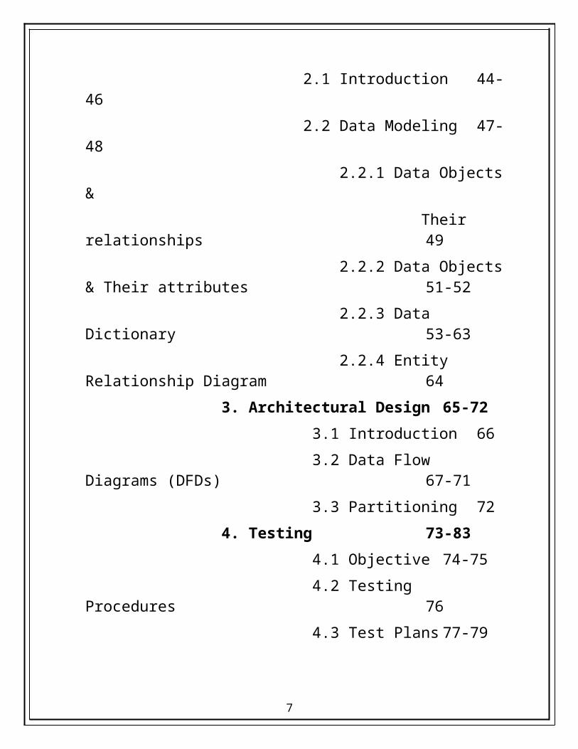
2.1 Introduction 44-46
2.2 Data Modeling 47-48
2.2.1 Data Objects &
Their relationships 49
5

2.2.2 Data Objects & Their attributes 51-52
2.2.3 Data Dictionary 53-63
2.2.4 Entity Relationship Diagram 64
3. Architectural Design 65-72
3.1 Introduction 66
3.2 Data Flow Diagrams (DFDs) 67-71
3.3 Partitioning 72
4. Testing 73-83
4.1 Objective 74-75
4.2 Testing Procedures 76
4.3 Test Plans 77-79
4.4 Cyclomatic Complexity 80-83
6
SOFTWARE
REQUIREMENT
SPECIFICATION
7

1. INTRODUCTION
1.1 OBJECTIVE
8

The origin of most software systems is in the need of a client, who either wants to automate the existing manual system or desires a new software system. The software system is itself created by the developer. Finally, the end user will use the completed system. Thus, there are three major parties interested in a new system: the client, the user, and the developer. Somehow the requirements for the system that will satisfy the needs of the clients and the concerns of the users have to be communicated to the developer. The problem is that the client doesn’t usually design the software or the software development process and the developer does not understand the client’s problem and the application area. This causes a communication gap between the parties involved in the development of the project.
The basic purpose of Software Requirement Specification (SRS) is to bridge this communication gap. SRS is the medium through which the client’s and the user’s needs are accurately specified; indeed SRS forms the basis of software development.
Another important purpose of developing an SRS is helping the clients understanding their own needs. An SRS establishes the basis for agreement between the client and the supplier on what the software product will do.An SRS provides a reference for validation of the final product.
A high quality SRS is a prerequisite to high quality software and it also reduces the development cost.
1.2 SCOPE9
"Airline Reservation System” is an attempt to simulate the basic concepts of an online Reservation system. The system enables to perform the following functions:
SEARCH FOR FLIGHTS
BOOKING OF A SELECTED FLIGHT
PAYMENT
CANCELLATION
OUT OF SCOPE
1. No trip management, hotel bookings, etc.. are included.2. The function is limited till the issue of tickets. No boarding
passes or other documents are issued.
LIMITATIONSThe administrator is intimidated through the internet about the changes in the flight schedules. He then, makes the necessary updation in the database.
10
1.3 DEFINTIONS AND ACRONYMS
1. DFD :- Data Flow Diagram
2. ERD :- Entity Relationship Diagram
3. SRS :- Software Requirements Specification
4. STD :- State Transition Diagram
11
1.4 OVERVIEW
Air transport industry is an area of commerce in which aircraft are employed to carry passengers, freight and mail etc. Air transport companies operate scheduled flights and non-scheduled services over local, regional, national and international routes.
Manually, it is very laborious and slow as well, to generate the seat assignments, flight scheduling, and aircraft loading hence an automation system of interaction with airlines reservation is necessitated. Airlines reservation system originated in the mid-1950s as relatively unsophisticated internal system to help with tasks (as above said).
Airlines reservation basically includes issuing tickets to passengers who want to fly to a particular destination a particular day and time.
Thus, the various activities that the airlines reservation encounter are checking the plane that flies to a particular from a starting point, checking the availability of seats in that particular flight and to issue the tickets if the seat is available. Then there is problem of cancellation. If a passenger for some reason wants to cancel a confirmed ticket, then the penalty is calculated based on the time the cancellation is made and the balance amount is refunded. The amount to be refunded is based upon the airlines’ cancellation policy.
12
2. OVERALL DESCRIPTION
13
2.1 PRODUCT PERSPECTIVE
Before the automation, the system suffered from the following
DRAWBACKS:
The existing system is highly manual involving a lot of paper work and calculation and therefore may be erroneous. This has lead to inconsistency and inaccuracy in the maintenance of data.
The data, which is stored on the paper only, may be lost, stolen or destroyed due to natural calamity like fire and water.
The existing system is sluggish and consumes a lot of time causing inconvenience to customers and the airlines staff.
Due to manual nature, it is difficult to update, delete, add or view the data.
Since the number of passengers have drastically increased therefore maintaining and retrieving detailed record of passenger is extremely difficult.
An airline has many offices around the world, an absence of a link between these offices lead to lack of coordination and communication.
14
Hence the airline reservation system is proposed with the following
PRODUCTION PERSPECTIVE:
The computerization of the reservation system will reduce a lot of paperwork and hence the load on the airline administrative staff.
The machine performs all calculations. Hence chances of error are nil.
The passenger, reservation, cancellation list can easily be retrieved and any required addition, deletion or updation can be performed.
The system provides for user-ID validation, hence unauthorized access is prevented.
15
2.2 PRODUCTION FUNCTIONS
Booking agents with varying levels of familiarity with computers will mostly use this system. With this in mind, an important feature of this software is that it be relatively simple to use. The scope of this project encompasses: -
Search : This function allows the booking agent to search for flights that are available between the two travel cities, namely the "Departure city" and "Arrival city" as desired by the traveller. The system initially prompts the agent for the departure and arrival city, the date of departure, preferred time slot and the number of passengers. It then displays a list of flights available with different airlines between the designated cities on the specified date and time.
Selection : This function allows a particular flight to be selected from the displayed list. All the details of the flight are shown :-
1. Flight Number2. Date, time and place of departure 3. Date, time and place of arrival 4. Flight Duration 5. Fare per head6. Number of stoppages – 0, 1, 2…
16

Review : If the seats are available, then the software prompts for the booking of flight. The flight information is shown. The total fare including taxes is shown and flight details are reviewed.
Traveller Information : It asks for the details of all the passengers supposed to travel including name, address, telephone number and e-mail id.
Payment : It asks the agent to enter the various credit card details of the person making the reservation.
1. Credit card type2. Credit card number3. CVC number of the card4. Expiration date of the card5. The name on the card
Cancellation : The system also allows the passenger to cancel an existing reservation. This function registers the information regarding a passenger who has requested for a cancellation of his/her ticket. It includes entries pertaining to the Flight No., Confirmation No., Name, Date of Journey, Fare deducted.
17

2.3 USER CHARACTERISTICS
EDUCATIONAL LEVEL :-At least user of the system should be comfortable with English language.
TECHNICAL EXPERTISE : - User should be comfortable using general purpose applications on the computer system.
2.4 PRINCIPLE ACTORS
Booking Agent
Customer/Passenger
Keyboard
Printer
Mouse
18

Internet
2.5 GENERAL CONSTRAINTS
Software constraints:
The system will run under windows98 or higher platforms of operating system.
2.6 ASSUMPTIONS
AND DEPENDICIES
Booking Agents will be having a valid user name an password to access the software
19

The software needs booking agent to have complete knowledge of airline reservation system.
Software is dependent on access to internet.
3. FUNCTIONAL REQUIREMENTS
20
3.1 USE CASES & SCREEN DUMPS
USE CASES
1.
Use case ID: - A user/agent wishes to login to the system.
Primary actor: - User/Booking agent.
Pre-condition: - Usernames and passwords must be available beforehand.Success End condition: - The main options screen is displayed.
Failed end condition: - User has entered incorrect username or password or both.
Main success scenario description1. Select the “Log In” option from the desktop.
21
2. The following screen is displayed
3. Enter the username and password in the respective input fields.4. Click the “Log In” button.5. The main options screen is displayed.
Scenario extension description4.a.1 Click the “Cancel” option.4.a.2 Desktop screen is displayed
4.b.1 Entered username or password or both are incorrect.
22

4.b.2 System asks to input again correctly, maximum up to 3 times, after which the system is blocked.
2.
Use case ID: - Search for flights
Goal in context:- Agent/user wishes to search for available flights b/w 2 cities for the chosen date
Primary actor: - Booking agent
Pre-condition:- Actor has successfully navigated to the main options screen.
Success end condition: - A list of flights matching the search criteria is presented.
Failed end condition: - A list of flights matching the search criteria is not presented.
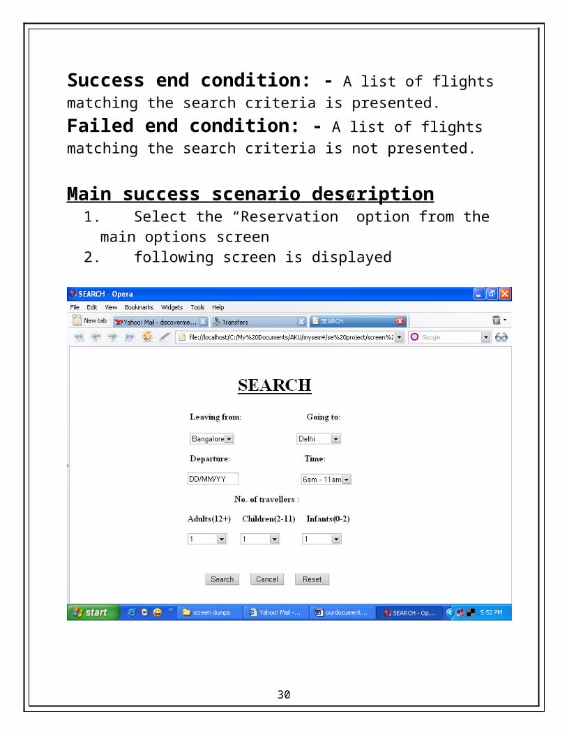
Main success scenario description1. Select the “Reservation” option from the main options screen2. following screen is displayed
23

3. Enter all the information in appropriate input fields4. Click the “Search” button5. A list of all flights that match the given requirements is displayed
Scenario extension description4.a.1 Select the “Cancel” button4.a.2 Main options screen is displayed.
4.b.1 All necessary fields are not displayed.4.b.2 The input fields are displayed from step2 with the input data and a note stating that certain required data is missing.
24
3.
Use case ID: - Selecting a flight.
Goal In context: - An agent wishes to select a particular flight from the list displayed.
Primary actor: - Booking agent.
Pre-condition:- Actor has successfully navigated to the search results.
Success end condition: - All the selected flight and fair details are presented.
Failed end condition: - No flight and fair details are presented.
Main success scenario description
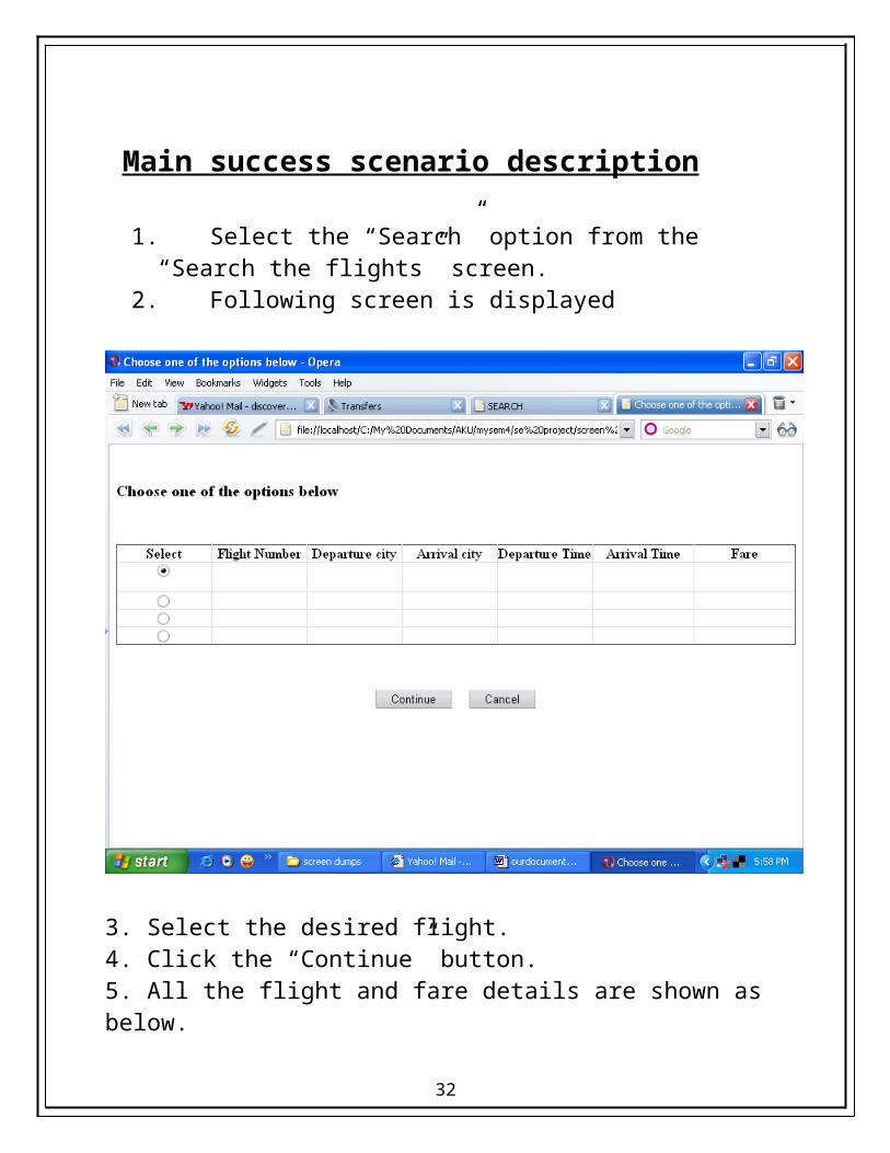
1. Select the “Search” option from the “Search the flights” screen.2. Following screen is displayed
25
3. Select the desired flight.4. Click the “Continue” button.5. All the flight and fare details are shown as below.
Scenario extension description4.a.1 Select the “Cancel” button4.a.2 Search results are displayed
26
4.
Use case ID: - Traveller information
Goal in context: - An agent wishes to enter the personal details of the passenger.
Primary actor: - Booking agent
Pre-condition:- Actor has successfully navigated to the review details.
Success end condition: - Payment screen is displayed.
Failed end condition: - Payment options screen is not displayed.
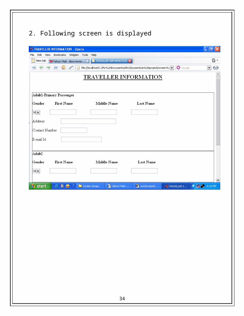
Main scenario screen description1. Select the “Continue” link form the review screen2. Following screen is displayed
27

28

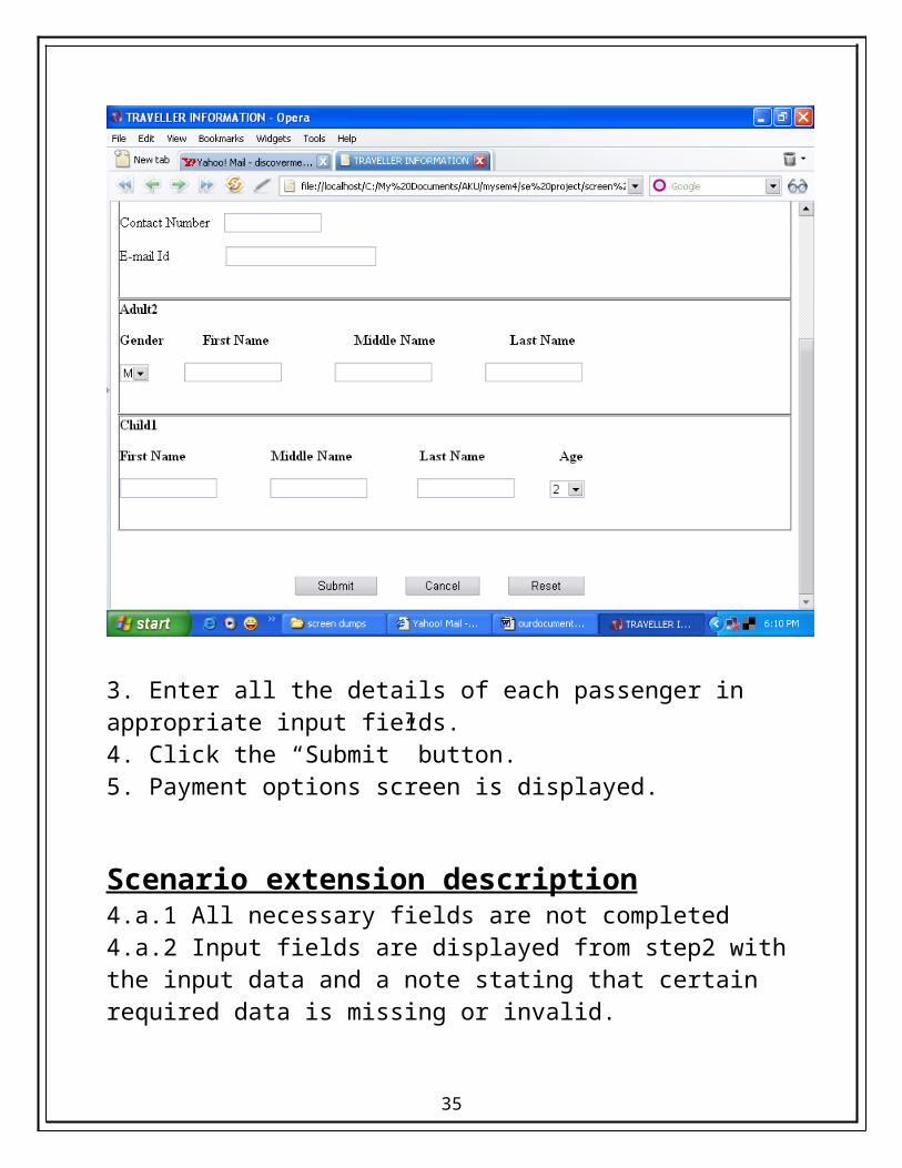
3. Enter all the details of each passenger in appropriate input fields.4. Click the “Submit” button.5. Payment options screen is displayed.
Scenario extension description4.a.1 All necessary fields are not completed4.a.2 Input fields are displayed from step2 with the input data and a note stating that certain required data is missing or invalid.
4.b.1 Select the “Cancel” button.4.b.2 Review details are displayed.
29
5.
Use case ID: - Payment
Goal in context: - Agent wishes to finalize the reservation by taking the payment from customer.
Primary actor: - Booking agent
Pre condition: - Actor has successfully navigated to the payment screen.
Success end condition: - A reservation has been made.
Failed end condition: - A reservation has not been made.
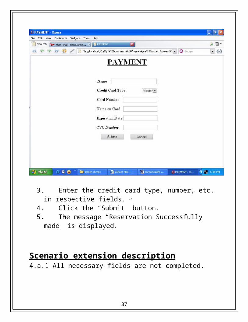
Main scenario screen description1. Click the “Submit” button from the traveller’s screen2. Following screen is displayed
30

3. Enter the credit card type, number, etc. in respective fields.4. Click the “Submit” button.5. The message “Reservation Successfully made” is displayed.
Scenario extension description4.a.1 All necessary fields are not completed.4.a.2 Input fields are displayed from step2 with the input data and a note stating that certain required data is missing or invalid.
4.b.1 Select the “Cancel” button.4.b.2 Review details are displayed.
31
6.
Use case ID: - Cancel Reservation
Goal in context: - A customer wishes to cancel a reservation.
Primary actor: - Booking agent
Pre - condition: - 1. A reservation has already been made. 2. Actor has successfully navigated to main
option screen.
Success end condition: - The selected reservation has been cancelled.
Failed end condition: - The selected reservation has not been cancelled.
Main scenario screen description
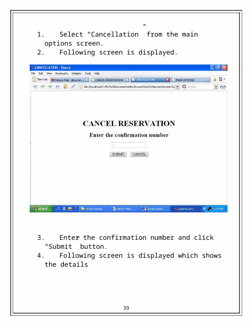
1. Select “Cancellation” from the main options screen.2. Following screen is displayed.
32

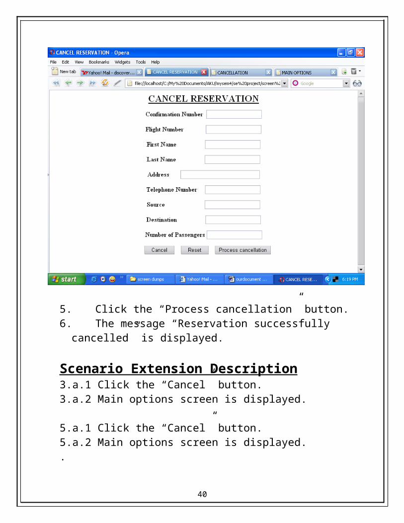
3. Enter the confirmation number and click “Submit” button.4. Following screen is displayed which shows the details
33
5. Click the “Process cancellation” button.6. The message “Reservation successfully cancelled” is displayed.
Scenario Extension Description3.a.1 Click the “Cancel” button.3.a.2 Main options screen is displayed.
5.a.1 Click the “Cancel” button.5.a.2 Main options screen is displayed..5.b.1 Actor may enter wrong confirmation number.5.b.2 The message “Invalid confirmation number” is displayed.
34
3.2 PERFORMANCE REQUIREMENTS
User friendliness : - The system is easy to learn and understand. A native user can also use the system effectively, without any difficulty.
User Satisfaction : - The system is such that it stands up to the user expectations.
Response Time: - The response of all the operation is good. This has been made possible by careful programming.
Error Handling : - Response to user errors and undesired situations has been taken care of to ensure that the system operates without halting.
Safety and Robustness : - The system is able to avoid or tackle disastrous action. In other words, it should be foul proof. The system safeguards against undesired events, without human intervention.
Portable : - The software should not be architecture specific. It should be easily transferable to other platforms if needed.
35

3.3 DESIGN CONSTRAINTS
There are a number of factors in the client’s environment that may restrict the choices of a designer. Such factors include standards that must be followed, resource limits, operating environment, reliability and security requirements and policies that may have an impact on the design of the system. An SRS (Software Requirements Analysis and Specification) should identify and specify all such constraints.
Standard Compliance: - This specifies the requirements for the standards the system must follow. The standards may include the report format and accounting properties.
Hardware Limitations :- The software may have to operate on some existing or predetermined hardware, thus imposing restrictions on the design. Hardware limitations can include the types of machines to be used, operating system available on the system, languages supported and limits on primary and secondary storage.
Reliability and Fault Tolerance : - Fault tolerance requirements can place a major constraint on how the system is to be designed. Fault tolerance requirements often make the system more complex and expensive. Requirements about system behavior in the face of certain kinds of faults are specified. Recovery requirements are often an integral part here, detailing what the system should do I some failure occurs to ensure certain properties.
36
Reliability requirements are very important for critical applications.
Security : - Security requirements are particularly significant in defense systems and database systems. They place restrictions on the use of certain commands, control access to data, provide different kinds of access requirements for different people, require the use of passwords and cryptography techniques and maintain a log of activities in the system.
37
3.4 HARDWARE REQUIREMENTS
For the hardware requirements the SRS specifies the logical characteristics of each interface b/w the software product and the hardware components. It specifies the hardware requirements like memory restrictions, cache size, the processor, RAM size etc... those are required for the software to run.
Minimum Hardware Requirements
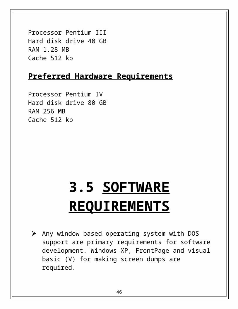
Processor Pentium IIIHard disk drive 40 GBRAM 1.28 MBCache 512 kb
Preferred Hardware Requirements
Processor Pentium IVHard disk drive 80 GBRAM 256 MBCache 512 kb
38
3.5 SOFTWARE REQUIREMENTS
Any window based operating system with DOS support are primary requirements for software development. Windows XP, FrontPage and visual basic (V) for making screen dumps are required.
The systems must be connected via LAN and connection to internet is mandatory.
3.6 OTHER REQUIREMENTS
Software should satisfy following requirements as well:-
SECURITY PORTABILITY CORRECTNESS EFFICIENCY FLEXIBILTY TESTABILTY REUSABILTY
39
SOFTWARE DESIGN
DOCUMENTATION
40
1. INTRODUCTION
41

1.1 INTRODUCTION
Software Design sits at the kernel of software engineering and is applied regardless of the software process model that is used. Beginning once software requirements have been analyzed and specified, software design is the first of three technical activities- designs, code, generation and test- that are required to build and verify the software. Each activity transforms information in a manner that ultimately results in validated computer software.
Software design is more creative process rather than analysis coz it deals with the development of the actual mechanics for a new workable system. While analyzing, it is possible to produce the correct model of an existing system. However, there is, no such thing a correct design. Good design is always system dependent and what is good design for one system may be bad for another.
A SRS document tells us what a system does, and becomes input to the design process, which tells us how a software system works. Designing software system means determining how requirements are realized and result is a software design document (SDD). Thus the purpose of the design phase is to produce a solution to a problem given in SRS document.
The flow of information during software design is illustrated in fig1. Software requirements, manifested by the data, functional and behavioral models feed the design tasks. Using number of design methods the design tasks produces a data design, an architectural design, an interface design and a component design.
42

1.2 SCOPE
The most challenging and creative phase of the system life cycle is SYSTEM DESIGN. It shows how the software system will be structured to satisfy the requirements identified in the SRS. It refers to the technical specifications that will meet the stated requirements. The design specifications that get generated at the end of this phase are technical in nature and are the blueprint for the implementation activity.
Thus the scope of SDD encompasses:-
User interface
Manual procedure
Data base design
Program structure
43

2. DATA DESIGN
44
2.1 INTRODUCTION
The data design transforms the information domain model created during analysis into the data structures that will be required to implement the software. The data object and relationships defined in the entity relationship diagram and the detailed data content depicted in the data dictionary provides the basis for the data design of software architecture.
Data design also referred as data architecting creates a model of data that is represented at a high level of abstraction. This data model is then refined into progressively more implementation specific representation that can be processed by the computer- based system. The data object defined during software requirement analysis is modeled using ERD. The data design translates these elements of the requirements model into data structures at the software component level and, when necessary, a database architecture at the application level.
45
46
DATA DESIGN
The data design consists of entity relationship diagram, data dictionary data structures and data modeling.
ARCHITECTURAL DESIGN
This document in software design document consists of data flow diagrams and architectural styles (Data flow architecture).
INTERFACE DESIGNThis document consists of state transition diagram, control specification document, process specification.
COMPONENT LEVEL DESIGNThis document consists of state transition diagram, control specification document, process specification.
The data design transforms the information domain model created during analysis into the data structures that will be required to implement the software.
The architectural design defines the relationship b/w major structural elements of the s/w that can be used to achieve the requirements that have been defined for the system and the constraints that affect the way in which architectural design patterns ca be applied.
The interface design describes how the s/w communicates within itself, with systems that interoperate with it, and with humans who use it.
The component level design transforms structural elements of the s/w architecture into a procedural description of s/w components.
47
DATA MODELLING
DATA MODELLING answers a set of specific questions that are relevant to any data processing application. It tells
Primary data objects to be processed Composition of such data object Attributes describing each data object Relationships b/w each data object and other objects.
48

At the core of the model lies the data dictionary- a repository that contains descriptions of all date objects consumed or produced by the software.
Three different diagrams surround the core. The entity relation diagram depicts relationships b/w data objects.
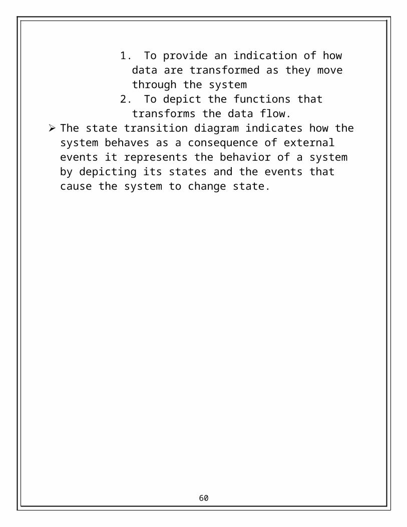
ERD is the notation that is used to conduct the data modeling activity. The data flow diagram serves two purposes:
1. To provide an indication of how data are transformed as they move through the system
2. To depict the functions that transforms the data flow. The state transition diagram indicates how the system behaves as a
consequence of external events it represents the behavior of a system
EntityRelationshipDiagram
Data FlowDiagram
State TransitionDiagram
DataDictionar
y
49
by depicting its states and the events that cause the system to change state.
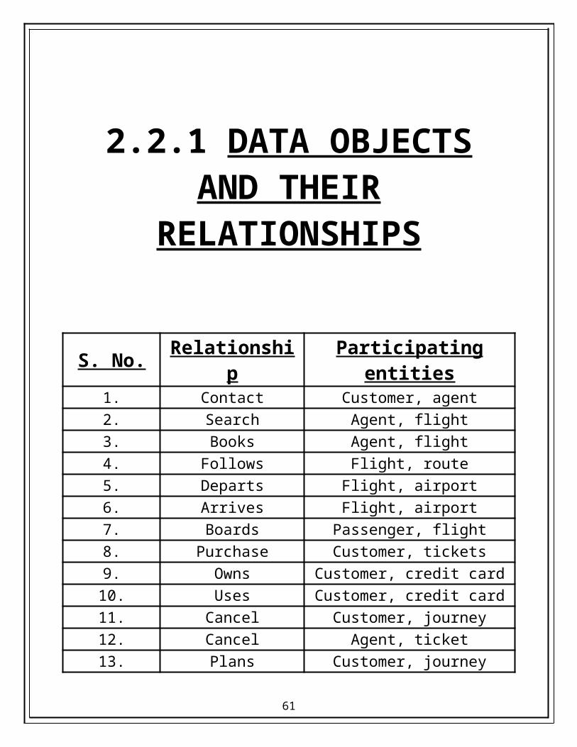
2.2.1 DATA OBJECTS AND THEIR
RELATIONSHIPS
50

S. No. Relationship Participating entities1. Contact Customer, agent2. Search Agent, flight3. Books Agent, flight4. Follows Flight, route5. Departs Flight, airport6. Arrives Flight, airport7. Boards Passenger, flight8. Purchase Customer, tickets9. Owns Customer, credit card10. Uses Customer, credit card11. Cancel Customer, journey12. Cancel Agent, ticket13. Plans Customer, journey14. Pays Customer, fare15. Receives Agent, fare
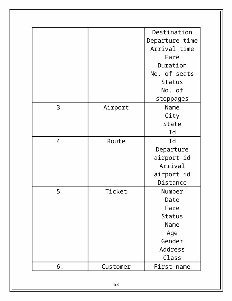
2.2.2 DATA OBJECTS AND THEIR
ATTRIBUTES
51
S.No. Entity Attributes1. Passenger First name
Last nameAddress
Phone no.e-mail idgender
2. Flight NumberSource
DestinationDeparture time
Arrival timeFare
DurationNo. of seats
StatusNo. of stoppages
3. Airport NameCityState
Id4. Route Id
Departure airport idArrival airport id
Distance5. Ticket Number
DateFare
StatusNameAge
52
GenderAddress
Class6. Customer First name
Last nameAge
GenderPhone no.Addresse-mail id
7. Credit card TypeNumber
Expiration dateName
CVC no.8. Booking agent Username
Password9. Journey Source
DestinationDuration
10. Fare BasicTaxes
No. of passengersTotal
53
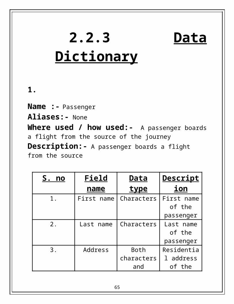
2.2.3 Data Dictionary
1.
Name :- Passenger
Aliases:- None
Where used / how used:- A passenger boards a flight from the source of the journey
Description:- A passenger boards a flight from the source
S. no Field name Data type Description1. First name Characters First name of
the passenger2. Last name Characters Last name of
the passenger3. Address Both
characters and numbers.
Residential address of the
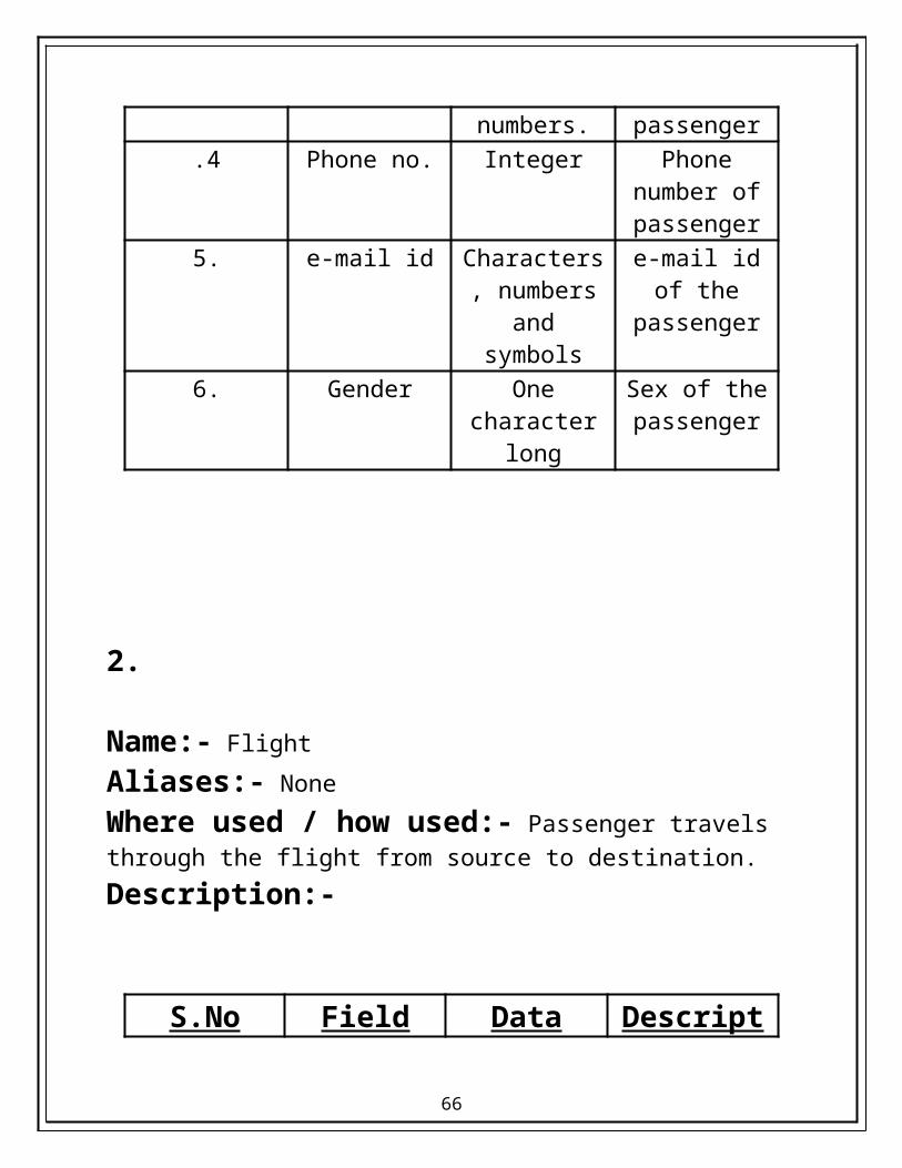
passenger.4 Phone no. Integer Phone number
of passenger5. e-mail id Characters,
numbers and symbols
e-mail id of the passenger
6. Gender One character long
Sex of the passenger
54

2.
Name:- Flight
Aliases:- None
Where used / how used:- Passenger travels through the flight from source to destination.
Description:-
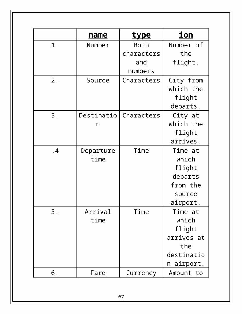
S.No Field name Data type Description1. Number Both
characters and numbers
Number of the flight.
2. Source Characters City from which the flight
departs.3. Destination Characters City at which
the flight arrives.
.4 Departure time Time Time at which flight departs
from the source airport.
5. Arrival time Time Time at which flight arrives at the destination
airport.6. Fare Currency Amount to be
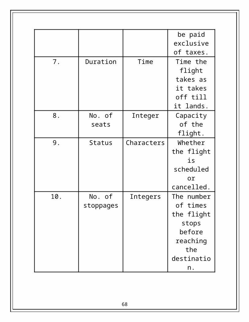
paid exclusive
55
of taxes.7. Duration Time Time the flight
takes as it takes off till it lands.
8. No. of seats Integer Capacity of the flight.
9. Status Characters Whether the flight is
scheduled or cancelled.
10. No. of stoppages
Integers The number of times the flight
stops before reaching the destination.
56
3.
Name:- Airport
Aliases:- None
Where used / how used:- A flight either arrives or departs from the airport.
Description:-
S.No Field name Data type Description1. City Characters Name of the
city where the airport is situated.
2. State Characters State of the country of to which the city
belongs.3. Country Characters Name of the
nation where the airport is
situated4. Airport-Id Both
characters and numbers.
Unique identification number of the
airport.
57
4.
Name:- Route
Aliases:- None
Where used / how used:- A flight follows the route to reach the destination.
Description:-
S.No Field name Data type Description1. Route-Id Both
characters and numbers.
Unique identification number of the
route.2. Departure
airport idBoth
characters and numbers.
Id of the airport from where the
flight for the route departs.
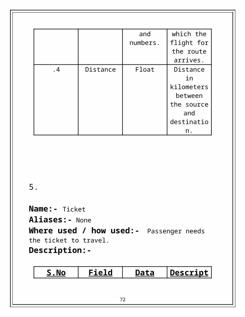
3. Arrival airport id
Both characters and
numbers.
Id of the airport at which the
flight for the route arrives.
.4 Distance Float Distance in kilometers
between the source and destination.
58

5.
Name:- Ticket
Aliases:- None
Where used / how used:- Passenger needs the ticket to travel.
Description:-
S.No Field name Data type Description1. Number Both
characters and numbers.
Unique identification
number of each ticket.
2. Date Date Date of departure of
flight for which the ticket is booked.
3. Fare Currency Amount that has been paid to book the
ticket..4 Status Characters Whether the
ticket is booked or cancelled.
5. Name Characters Name of the passenger.
59
6. Age Integer Age of the passenger
7. Gender One character long
Sex of the passenger.
8. Address Both characters and
numbers.
Residential address of the
passenger.9. Class Characters Whether the
ticket is for economy or executive
class.
60
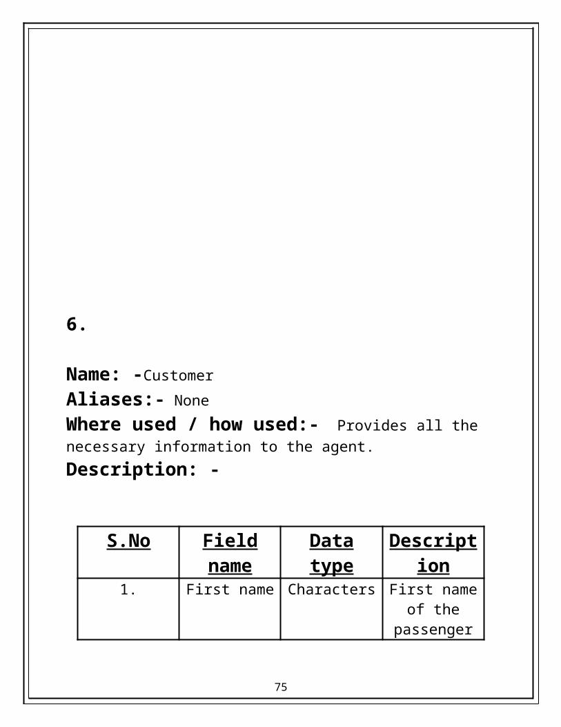
6.
Name: -Customer
Aliases:- None
Where used / how used:- Provides all the necessary information to the agent.
Description: -
S.No Field name Data type Description1. First name Characters First name of
the passenger2. Last name Characters Last name of
the passenger3. Age Integer Age of the
passenger4. Address Both
characters and numbers.
Residential address of the
passenger.
5. Phone no. Integer Phone number of passenger
6. e-mail id Characters, numbers and
symbols
e-mail id of the passenger
7. Gender One character long
Sex of the passenger
61

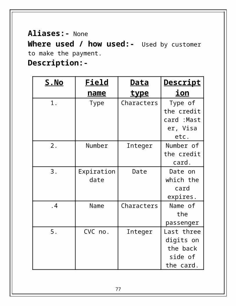
7.
Name:- Credit card
Aliases:- None
Where used / how used:- Used by customer to make the payment.
Description:-
S.No Field name Data type Description1. Type Characters Type of the
credit card :Master,
Visa etc.2. Number Integer Number of the
credit card.3. Expiration date Date Date on which
the card expires.
.4 Name Characters Name of the passenger
5. CVC no. Integer Last three digits on the back side of
the card.
62
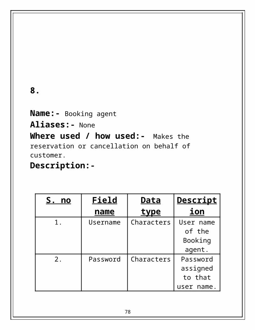
8.
Name:- Booking agent
Aliases:- None
Where used / how used:- Makes the reservation or cancellation on behalf of customer.
Description:-
S. no Field name Data type Description1. Username Characters User name of
the Booking agent.
2. Password Characters Password assigned to that
user name.
63

9.
Name:- Journey
Aliases:- none
Where used / how used:- Planned by the customer/passenger.
Description:-
S.No Field name Data type Description1. Source Characters Name of the
city & country from where the journey begins.
2. Destination Characters Name of the city & country
the journey ends.
3. Duration Integer For how many days the
journey is scheduled for.
64
10.
Name:- Fare
Aliases:- None
Where used / how used:- A customer pays fare to make a reservation final.
Description:-
S.No Field name Data type Description1. Basic Currency Basic fare to
be paid per head.
2. Taxes Float Taxes to be applied to the
basic fare.3. No. of
passengersInteger Number of
people making the journey.
4. Total Currency Total fare to be paid for all
heads.
65
2.2.4 ENTITY RELATIONSHIP
DIAGRAM
66
cancel
knows
receives
pays
follows
boards
contacts
FARE
CUSTOMER
ROUTEPASSENGER JOURNEY
CREDIT CARD
uses
owns
plans
search
books
cancel
TICKET
purchase
arrives
departs
AIRPORT
FLIGHT AGENT
67
3. ARCHITECTURAL DESIGN
68

3.1 INTRODUCTION
The architectural design defines the relationship between major structural elements of the software, the design pattern that can be used to achieve the requirements that have been defined for the system, and the constraints that affect the way in which architectural design patterns that- can be applied. The architectural design representation-the framework of the computer-based system- can be derived from the system specification, the analysis model and the interaction of sub systems defined within the analysis model.
69

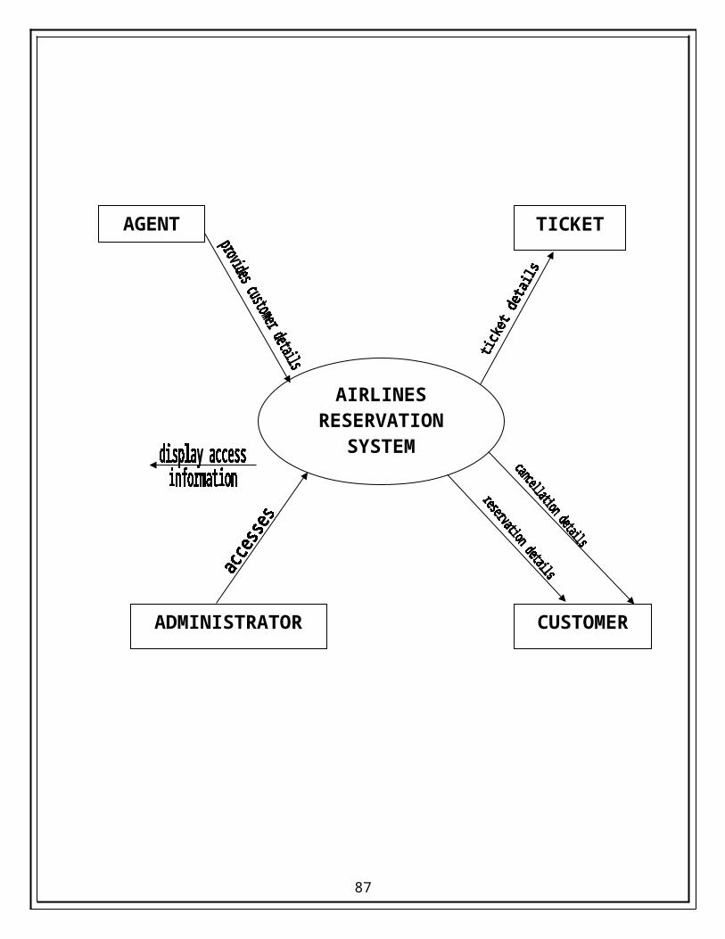
3.2 DATA FLOW DIAGRAMS
LEVEL 0 DFD
70
AIRLINES RESERVATION
SYSTEM
AGENT TICKET
ADMINISTRATOR CUSTOMER

LEVEL1 DFD
LOGIN DETAILS
RESERVATION DATABASE
71
RESERVATION
AGENT
LOGIN
CANCELLATION
ADMINISTRATOR TICKET CUSTOMER
AGENT
ADMINISTRATOR
READ INPUT
VERIFY USERNAME
& PASSWORD
FLIGHT
LEVEL 2 DFD - LOGIN
MAIN OPTIONS SCREEN
LOGIN DETAILS
72

AGENT
SEARCH
SELECT
TRAVELLER INFORMATION
PAYMENT
ADMINIST-RATOR
CUSTOMER
TICKET DETAILS
ERROR MESSAGE
LEVEL 2 DFD – RESERVATION
FLIGHTS
73

AGENT
READ DETAILS
VERIFY DETAILS
PROCESS CANCELLATION
RESERVATION DATABASE
LEVEL 2 DFD – CANCELLATION
RESERVATION DETAILS
74
CUSTOMER
3.3 PARTIONING
AIRLINE RESERVATION SYSTEM
LOGIN RESERVATION CANCELLATION
SEARCH SELECTION REVIEW TRAVELLER PAYMENT INFORMATION
75

4. TESTING OF THE DOCUMENT
76
TESTING often accounts for more project than any other software engineering activity. If it is conducted haphazardly, time is wasted, unnecessary effort is expended, and even worse, errors sneak through undetected. It would therefore seem reasonable to establish a systematic strategy for testing software. The software testing is a critical step of the software quality assurance and represents the ultimate review of specification, design and code generation.
4.1 OBJECTIVE OF SYSTEM TESTING
Once a system has been designed, it is necessary to undergo an exhaustive testing before installing the system. This is important because in some cases a small system error, not detect and corrected early before installation, may explode into a much larger problem later on. Testing is performed when user is asked to assist in identifying all possible situations. That might arise as regards the factors that effort was put to tackle the problem under consideration.
77
Any engineering product can be tested in one of two ways:
Knowing the specified function that a product has been designed to perform.
Knowing the internal working of the product.
The first test approach is called black box testing and the second, white box testing.
When computer software is considered, black box testing alludes to tests that are conducted at the software interface. Although they are designed to uncover errors, black box tests are used to demonstrate that software functions are operational, that input is properly accepted and output is correctly produced, and the integrity of external information is maintained. A black box test examines some fundamental aspects of a system with little regard for the internal logical structure of the software.
White box testing of software is predicted on close examination of procedural detail. Providing test cases that exercise specific conditions and/or loops tests logical paths through the software.
During development, the software has to pass through a number of stages. At each of these stages we have the probability of committing errors. It is actually the inability of humans to communicate with perfection that introduces a step of quality assurance, which is carried out after software development. Testing represents the ultimate review of specification, design and coding.
Testing is carried out with the intent of finding errors, which always exist in software, no matter how stringent the checks may be. This step can never show the defects, it can only show their presence.
78

4.2 TESTING PROCEDURES
There are three testing procedures: -
UNIT TESTING : - This is the testing of an individual module and is usually carried out to ensure the validity of a particular module.
NOTE: It makes use of white box testing technique.
INTEGRATED TESTING : - Integrated testing is the testing of the system modules. This is done to identify errors, which relate to the interaction of different module, which cannot be found by unit testing but only through an interactive testing.
NOTE: It makes use of black box testing technique.
79

SYSTEM TESTING : - System testing is the testing of the system against its initial objectives. It is done either in a simulated environment or in a live environment.
VALIDATION TESTING : - Validation testing is the testing where requirement established as part of software requirement analysis are validated against the software that has been constructed.
NOTE: It makes use of black box testing technique.
4.3 TEST PLANS
S.No Test caseExpected
RequirementsExceptions
1.Login
Username should consist of characters & numbers. Username should start with characters. Password should start with characters & must be exactly 6 characters long. Password should not contain special symbols.
Using spaces may result in error. Username & password in different case will not be acceptable.
2.Search &
Select
Departure & Arrival city should be valid. Departure & Arrival
Using different date or time format will result in errors.
80

dates should refer to future. Time should be in am/pm format. Flight should consist of letters & digits. Only one of the scheduled flights should be selected at a time.
3.Traveller’s Information
First, middle, and last names should be no more than 20 characters. Telephone number should consist of valid STD code of the area. E-mail Id should follow standard format. Pin code should be of exactly 6 digits.
Using spaces in first, middle or last names will result in error. Use of more than required number of digits in telephone number will result in error.
4. Payment
Card type should be Master, Visa or American Express. Card number should be 14, 15 or 16 digits. Card number should either begin with 4, 5 or 3. Expiration date should be valid.
Entering card with leading digit other than 3, 4 or 5 will not be acceptable. Expired card will not be accepted.
5. Confirmation Confirmation Number should be automatically generated. Confirmation Number should consist of flight
If wrong payment details are entered, confirmation number will not be generated.
81

number & digits. Tickets should contain all the relevant information. Each ticket should bear a unique number.
6. Cancellation
Valid confirmation number should be entered to proceed to cancellation process. Cancellation of only future reservation can be made.
Using flight number or spaces in confirmation number will cause an error.
USER REQUIREMENT
FULFILLED REQUIREMENT
1. All the necessary fields should be set up to search for flights.
2. All the field entries should follow the indicated format.
“Submit” button on search screen doesn’t proceed further until all fields are filled in correctly.
82

4.4 CYCLOMATIC COMPLEXITY
It is software metric that provides a quantitative measure of the logical complexity of a program. The value computed for cyclomatic complexity defines the number of independent paths in the basis set of a program and provide us with an upper bound for the number of test that must be conducted to ensure that all statements have been executed at least once.
An independent path must move along at least one edge that has been traversed before the path is defined.
Cyclomatic complexity (V(G)) can be computed in the following ways.
1. V(G) = Number of Regions.2. V(G) = Number of edges – Number of Nodes + 2.3. V(G) = Number of Predicate Nodes +1.
Predicate nodes are the decision nodes. They are characterized by two or more edges emerging from them.
The following steps can be applied to derive the basis set:
83

1. Using the design or code as foundation, draw a corresponding flow graph.
2. Determine the cyclomatic complexity of the resultant flow graph.3. Determine the basis set of linearly independent paths.4. Prepare test cases that will force execution of each path in the basis
set.
void login(){
int correctpwd=0;int i;while(correctpwd==0){
int correct=0;while(correct==0){
cout<<“Enter username”;gets(username);int flag=0;for(i=0;i<10;i++){
if(username==log[i].user)flag=1;
if(flag==1)correct=1;
elsecout<<“Invalid”;
}}cout<<“Enter password”;gets(pwd);
84
1
2
34
5
6
78
910
11
12
13
14
15

if(pwd==log[i].pwd)correctpwd=1;
else{
cout<<“Invalid password”;correct=0;
}}
}
85
16
17
18
19
1
19
3
4
5
6
7
98
10
11
12
13
14
15
16
17
2
86
18
1. Number of Nodes = 19.2. Number of edges. = 24.3. Number of Predicate Nodes = 6.4. Number of Regions = 7.
Cyclomatic complexity
1. V(G) = 7.2. V(G) = 24 -19 +2 = 7.3. V(G) = 6 + 1 = 7.
Independent paths
P1 : 1 – 2 – 19 P2 : 1 – 2 – 3 – 4 – 5 – 6 – 7 – 9 – 10 – 12 – 13 – 14 – 15 – 16 – 18 – 2 - …..P3 : 1 – 2 – 3 – 4 – 5 – 6 – 7 – 8 – 9 – 10 – 12 – 13 – 14 – 15 – 16 – 19 – 2 - …..P4 : 1 – 2 – 3 – 4 – 5 – 6 – 7 – 8 – 9 – 11 – 12 – 13 – 14 – 15 – 16 – 18 – 2 - …..P5 : 1 – 2 – 3 – 4 – 5 – 6 – 7 – 8 – 9 – 11 – 12 – 13 – 14 – 15 – 17 – 18 – 2 - …..P6 : 1 – 2 – 3 – 4 – 5 – 6 – 7 – 9 – 11 – 12 – 6 – …..P7 : 1 – 2 – 3 – 4 – 5 – 6 – 7 – 9 – 11 – 12 – 13 – 4 – …..
87


