56
AirLink LS300 Hardware User Guide 4112895 Rev 6

AirLink LS300
Hardware User Guide
4112895Rev 6

Preface
Important Notice
Due to the nature of wireless communications, transmission and reception of data can never be guaranteed. Data may be delayed, corrupted (i.e., have errors) or be totally lost. Although significant delays or losses of data are rare when wireless devices such as the Sierra Wireless modem are used in a normal manner with a well-constructed network, the Sierra Wireless modem should not be used in situations where failure to transmit or receive data could result in damage of any kind to the user or any other party, including but not limited to personal injury, death, or loss of property. Sierra Wireless accepts no responsibility for damages of any kind resulting from delays or errors in data transmitted or received using the Sierra Wireless modem, or for failure of the Sierra Wireless modem to transmit or receive such data.
Safety and Hazards
Do not operate the Sierra Wireless modem in areas where blasting is in progress, near medical equipment, near life support equipment, or any equipment which may be susceptible to any form of radio interference. In such areas, the Sierra Wireless modem MUST BE POWERED OFF. The Sierra Wireless modem can transmit signals that could interfere with this equipment.
The driver or operator of any vehicle should not operate the Sierra Wireless modem while in control of a vehicle. Doing so will detract from the driver or operator's control and operation of that vehicle. In some states and provinces, operating such communications devices while in control of a vehicle is an offence.
In accordance with ANSI/ISA 12.12.1-2011, Section 16 and CSA C22.2 No 213, Section 5.5, the following instructions and warnings apply:
This apparatus is suitable for use in Class I, Division 2, Groups A, B, C and D classified Hazardous Locations.
Warning: EXPLOSION HAZARD–SUBSTITUTION OF COMPONENTS MAY IMPAIR SUITABILITY FOR CLASS I, DIVISION 2.
Avertrissement: RISQUE D’EXPLOSION-LA SUBSTITUTION DE COMPOSANTS PEUT RENDRE CE MATERIEL INACCEPTABLE POUR LES EMPLACEMENTS DE CLASSE I, DIVSION 2.
Warning: EXPLOSION HAZARD–DO NOT DISCONNECT WHILE CIRCUIT IS LIVE UNLESS THE AREA IS KNOWN TO BE NON-HAZARDOUS.
Avertrissement: RISQUE D’EXPLOSION-NE PAS DEBRANCHER TANT QUE LE CIRCUIT EST SOURS TENSION, A MOINES QU’IL NE S’AGISSE D’UN EMPLACEMENT NON DANGEREUX.
Warning: DO NOT USE THE USB CONNECTOR IN A HAZARDOUS AREA.
Avertrissement: NE PAS UTILISER DE CONNECTEUR USB DANS LES ENVIRONNEMENTS DANGEREUX.
Rev 6 May.15 3

AirLink LS300 Hardware User Guide
Warning: DO NOT USE THE RESET BUTTON IN A HAZARDOUS AREA.
Avertrissement: NE PAS UTILISER LE BOUTON DE RESET DANS UN ENVIRONNEMENT DANGEREUX.
Limitation of Liability
The information in this manual is subject to change without notice and does not represent a commitment on the part of Sierra Wireless. SIERRA WIRELESS AND ITS AFFILIATES SPECIFICALLY DISCLAIM LIABILITY FOR ANY AND ALL DIRECT, INDIRECT, SPECIAL, GENERAL, INCIDENTAL, CONSEQUENTIAL, PUNITIVE OR EXEMPLARY DAMAGES INCLUDING, BUT NOT LIMITED TO, LOSS OF PROFITS OR REVENUE OR ANTICIPATED PROFITS OR REVENUE ARISING OUT OF THE USE OR INABILITY TO USE ANY SIERRA WIRELESS PRODUCT, EVEN IF SIERRA WIRELESS AND/OR ITS AFFILIATES HAS BEEN ADVISED OF THE POSSIBILITY OF SUCH DAMAGES OR THEY ARE FORESEEABLE OR FOR CLAIMS BY ANY THIRD PARTY.
Notwithstanding the foregoing, in no event shall Sierra Wireless and/or its affiliates aggregate liability arising under or in connection with the Sierra Wireless product, regardless of the number of events, occurrences, or claims giving rise to liability, be in excess of the price paid by the purchaser for the Sierra Wireless product.
Patents This product may contain technology developed by or for Sierra Wireless Inc. This product includes technology licensed from QUALCOMM®. This product is manufactured or sold by Sierra Wireless Inc. or its affiliates under one or more patents licensed from InterDigital Group and MMP Portfolio Licensing.
Copyright © 2015 Sierra Wireless. All rights reserved.
Trademarks Sierra Wireless®, AirPrime®, AirLink®, AirVantage®, ALEOS® and the Sierra Wireless logo are registered trademarks of Sierra Wireless.
Windows® and Windows Vista® are registered trademarks of Microsoft Corporation.
Macintosh® and Mac OS X® are registered trademarks of Apple Inc., registered in the U.S. and other countries.
QUALCOMM® is a registered trademark of QUALCOMM Incorporated. Used under license.
Other trademarks are the property of their respective owners.
4 4112895
Preface
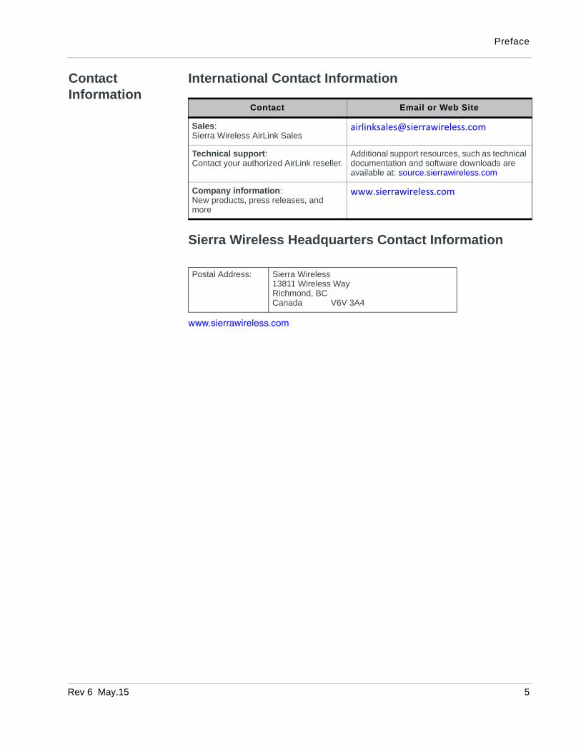
Contact Information
International Contact Information
Sierra Wireless Headquarters Contact Information
www.sierrawireless.com
Contact Email or Web Site
Sales:Sierra Wireless AirLink Sales
Technical support:Contact your authorized AirLink reseller.
Additional support resources, such as technical documentation and software downloads are available at: source.sierrawireless.com
Company information:New products, press releases, and more
www.sierrawireless.com
Postal Address: Sierra Wireless13811 Wireless WayRichmond, BCCanada V6V 3A4
Rev 6 May.15 5

AirLink LS300 Hardware User Guide
6 4112895

Rev 6 May
Contents
Introduction to the AirLink LS300 . . . . . . . . . . . . . . . . . . . . . . . . . . . . . . . . . . .9
Description . . . . . . . . . . . . . . . . . . . . . . . . . . . . . . . . . . . . . . . . . . . . . . . . . . 10
AirLink LS300 Device Configuration and Management . . . . . . . . . . . . . . . . 11
Accessories Available . . . . . . . . . . . . . . . . . . . . . . . . . . . . . . . . . . . . . . . . . 11
Specifications at a Glance . . . . . . . . . . . . . . . . . . . . . . . . . . . . . . . . . . . . . . . .13
Installation and Startup . . . . . . . . . . . . . . . . . . . . . . . . . . . . . . . . . . . . . . . . . .17
Tools and Materials Required . . . . . . . . . . . . . . . . . . . . . . . . . . . . . . . . . . . 17
Installation Overview . . . . . . . . . . . . . . . . . . . . . . . . . . . . . . . . . . . . . . . . . . 17
Step 1—Insert the SIM Card . . . . . . . . . . . . . . . . . . . . . . . . . . . . . . . . . . . . 18
Step 2—Connect the Antennas . . . . . . . . . . . . . . . . . . . . . . . . . . . . . . . . . . 18
Step 3—Connect the Data Cables. . . . . . . . . . . . . . . . . . . . . . . . . . . . . . . . 19
Step 4—Connect the Power . . . . . . . . . . . . . . . . . . . . . . . . . . . . . . . . . . . . 21
Power Connector on the LS300 . . . . . . . . . . . . . . . . . . . . . . . . . . . . . . . .22
Pin 4 (General Purpose I/O) . . . . . . . . . . . . . . . . . . . . . . . . . . . . . . . . . .24
Step 5—Check the device operation . . . . . . . . . . . . . . . . . . . . . . . . . . . . . . 26
LED Behavior . . . . . . . . . . . . . . . . . . . . . . . . . . . . . . . . . . . . . . . . . . . . . .26
Ethernet LEDs . . . . . . . . . . . . . . . . . . . . . . . . . . . . . . . . . . . . . . . . . . . . .27
Step 6—Startup and Software Configuration. . . . . . . . . . . . . . . . . . . . . . . . 27
Step 7—Mounting the LS300. . . . . . . . . . . . . . . . . . . . . . . . . . . . . . . . . . . . 28
Mounting Brackets . . . . . . . . . . . . . . . . . . . . . . . . . . . . . . . . . . . . . . . . . .29
Flat Surface Mount . . . . . . . . . . . . . . . . . . . . . . . . . . . . . . . . . . . . . . . . . .29
DIN Rail Mount . . . . . . . . . . . . . . . . . . . . . . . . . . . . . . . . . . . . . . . . . . . . .30
Rebooting the LS300 . . . . . . . . . . . . . . . . . . . . . . . . . . . . . . . . . . . . . . . . . . 31
Reset the LS300 to factory default settings . . . . . . . . . . . . . . . . . . . . . . . . . 31
AirLink LS300 Specifications . . . . . . . . . . . . . . . . . . . . . . . . . . . . . . . . . . . . .33
Antenna Specifications . . . . . . . . . . . . . . . . . . . . . . . . . . . . . . . . . . . . . 33
.15 7

AirLink LS300 Hardware User Guide
8
RF Specifications. . . . . . . . . . . . . . . . . . . . . . . . . . . . . . . . . . . . . . . . . . . . . 34
Frequency Bands . . . . . . . . . . . . . . . . . . . . . . . . . . . . . . . . . . . . . . . 34
Radio Module Conducted Transmit Power . . . . . . . . . . . . . . . . . . . . . . . 35
SIM Socket (HSPA Devices) . . . . . . . . . . . . . . . . . . . . . . . . . . . . . . . . . . . . 37
GPS Specifications . . . . . . . . . . . . . . . . . . . . . . . . . . . . . . . . . . . . . . . . . . . 37
Environmental Specifications. . . . . . . . . . . . . . . . . . . . . . . . . . . . . . . . . . . . 38
Reliability Specifications . . . . . . . . . . . . . . . . . . . . . . . . . . . . . . . . . . . . . . . 38
Mechanical Specifications . . . . . . . . . . . . . . . . . . . . . . . . . . . . . . . . . . . . . . 40
Power Specifications . . . . . . . . . . . . . . . . . . . . . . . . . . . . . . . . . . . . . . . . . 41
Power Consumption . . . . . . . . . . . . . . . . . . . . . . . . . . . . . . . . . . . . . . . . . 42
AC Power Adapter Specifications . . . . . . . . . . . . . . . . . . . . . . . . . . . . . . . . 43
Regulatory Information . . . . . . . . . . . . . . . . . . . . . . . . . . . . . . . . . . . . . . . . . . 45
Important Information for North American Users . . . . . . . . . . . . . . . . . . . . . 45
RF Exposure . . . . . . . . . . . . . . . . . . . . . . . . . . . . . . . . . . . . . . . . . . . . . . 45
EU . . . . . . . . . . . . . . . . . . . . . . . . . . . . . . . . . . . . . . . . . . . . . . . . . . . . . . . . 46
Acronyms . . . . . . . . . . . . . . . . . . . . . . . . . . . . . . . . . . . . . . . . . . . . . . . . . . . . 47
Index. . . . . . . . . . . . . . . . . . . . . . . . . . . . . . . . . . . . . . . . . . . . . . . . . . . . . . . . . 53
4112895

Rev 6 Apr.
1
1: Introduction to the AirLink LS300The AirLink® LS300 is a compact, intelligent and fully-featured communications platform that provides real-time wireless capabilities for fixed and mobile applications. It is intended for use in industrial setting such as:
• Remotely monitoring and controlling infrastructure and surveil-lance equipment on pipelines, meters, pumps and valves in any energy, utility, or industrial application
• Tracking the location of heavy equipment and assets in the field
• Providing reliable Internet access to a mobile workforce
The AirLink LS300 has multiple communication ports including serial, Ethernet, and USB ports. The power connector has one GPl I/O pin for remote monitoring and control and one ignition sense pin to turn the device on and off and trigger the low power mode.
The AirLink LS300 is a 3G cellular device that supports a variety of radio bands options, both on HSPA+ or CDMA EV-DO mobile broadband technology.
The AirLink LS300, when coupled with the rich embedded intelligence provided by the embedded ALEOS® software, is the perfect choice for a broad set of machine to machine solutions.
13 9
AirLink LS300 Hardware User Guide
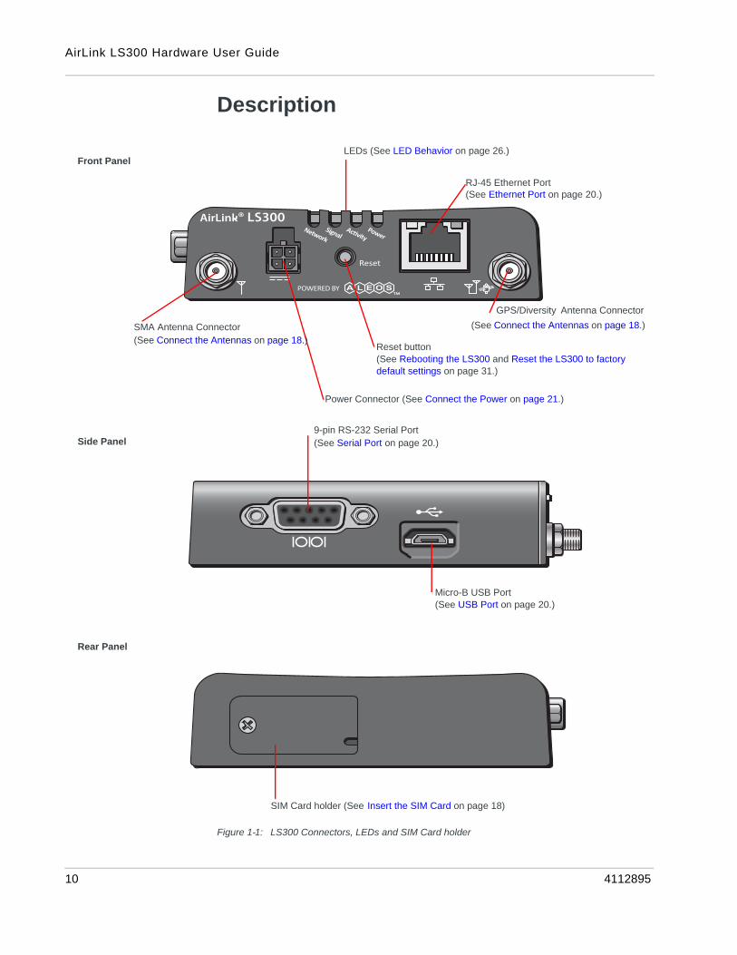
Description
Figure 1-1: LS300 Connectors, LEDs and SIM Card holder
Rear Panel
SMA Antenna Connector
RJ-45 Ethernet Port
GPS/Diversity Antenna Connector
Front Panel
9-pin RS-232 Serial Port
Micro-B USB Port
Side Panel
SIM Card holder (See Insert the SIM Card on page 18)
Power Connector (See Connect the Power on page 21.)
Reset button (See Rebooting the LS300 and Reset the LS300 to factory default settings on page 31.)
LEDs (See LED Behavior on page 26.)
(See Ethernet Port on page 20.)
(See Connect the Antennas on page 18.)
(See Connect the Antennas on page 18.)
(See Serial Port on page 20.)
(See USB Port on page 20.)
10 4112895

Introduction to the AirLink LS300
AirLink LS300 Device Configuration and Management
You can configure and manage your AirLink LS300 using:
• ACEmanager —a browser-based application
Refer to the ALEOS Software Configuration User Guide available for down-load at source.sierrawireless.com.
• AirLink Management Service (ALMS)—a cloud-based device management service provided by Sierra Wireless®
For more information on ALMS, visit: www.sierrawireless.com/ALMS
or contact your Sierra Wireless distributor.
• AT Commands
For a complete list of AT Command, refer to the ALEOS Software Configura-tion User Guide
Accessories Available
• DIN rail mounting bracket
• Screw-in mounting bracket
• Antennas: GPS and Cellular for CDMA and GSM
• AC 12VDC power adapter
• DC power cord
• Cigarette lighter adapter
• Ethernet cable
• DB-9 serial cable (6 ft and 25 ft lengths)
• USB cable
Rev 6 Apr. 13 11

AirLink LS300 Hardware User Guide
12 4112895
Rev 6 Apr.
2
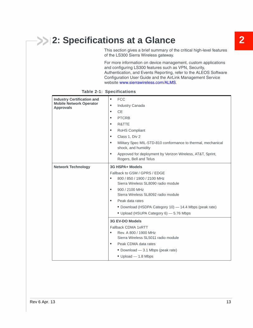
2: Specifications at a GlanceThis section gives a brief summary of the critical high-level features of the LS300 Sierra Wireless gateway.For more information on device management, custom applications and configuring LS300 features such as VPN, Security, Authentication, and Events Reporting, refer to the ALEOS Software Configuration User Guide and the AirLink Management Service website www.sierrawireless.com/ALMS.
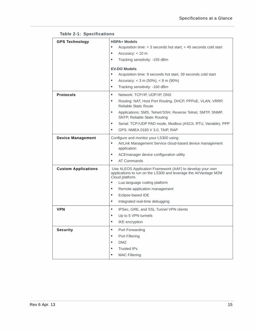
Table 2-1: Specifications
Industry Certification and Mobile Network Operator Approvals
• FCC
• Industry Canada
• CE
• PTCRB
• R&TTE
• RoHS Compliant
• Class 1, Div 2
• Military Spec MIL-STD-810 conformance to thermal, mechanical shock, and humidity
• Approved for deployment by Verizon Wireless, AT&T, Sprint, Rogers, Bell and Telus
Network Technology 3G HSPA+ Models
Fallback to GSM / GPRS / EDGE
• 800 / 850 / 1900 / 2100 MHz Sierra Wireless SL8090 radio module
• 900 / 2100 MHzSierra Wireless SL8092 radio module
• Peak data rates
• Download (HSDPA Category 10) — 14.4 Mbps (peak rate)
• Upload (HSUPA Category 6) — 5.76 Mbps
3G EV-DO Models
Fallback CDMA 1xRTT
• Rev. A 800 / 1900 MHzSierra Wireless SL5011 radio module
• Peak CDMA data rates
• Download — 3.1 Mbps (peak rate)
• Upload — 1.8 Mbps
13 13

AirLink LS300 Hardware User Guide
Host Interfaces • 10/100 Base-T RJ45 Ethernet
• RS-232 serial port
• USB V2.0 Micro-B connector
• 2 SMA antenna connectors (Primary, GPS/Diversity)
• Active antenna support
Input / Output Configurable I/O pin on power connector
• Digital Input ON voltage: 3.3 to 30 VDC
• Digital input OFF voltage: 0 to 1.2 VDC
• Analog input voltage: 0 to 30 VDC
• Open collector output < 200mA @ 30 VDC: 3.3 to 30 VDC
Power Adapter pins 4-Pin connector:
• Power
• Ground
• Configurable digital I/O and analog voltage input sensing
• Configurable ignition sense (Low Power Mode Enable Input)
Reset • Manual reset button or using ACEmanager
LEDs 4 LEDs:
• Network
• Signal
• Activity
• Power
Dimensions • 3.0 in x 3.5 in x 1.0 in(76 mm x 90 mm x 25 mm)
• 6.7 oz. (190 g)
Screw Torque Settings • M3 DIN rail mount screws
10 in-lb. (1.1 N-m)
Antennas
Finger tight (5–7in-lb.) is sufficient and the max torque should not go beyond 10 in-lb. (1.1 N-m).
Power Consumption All values in mA @ 12 VDC
• HSPA+: Idle 224, typical 245, maximum 430
• CDMA: Idle 220, typical 257, maximum 427
• Low power standby mode: < 68
• Analog ignition sense and power management
• Input voltage: 7–28 VDC
Operating Temperature -30°C to +70°C (-22°F to 158°F) full 3GPP RF compliance-40°C to +85°C (-40°F to 185°F) reduced RF performance
Humidity 90% RH @ 60°C
Reverse Polarity Protection
Compliant
Table 2-1: Specifications
14 4112895
Specifications at a Glance
GPS Technology HSPA+ Models
• Acquisition time: < 3 seconds hot start, < 45 seconds cold start
• Accuracy: < 10 m
• Tracking sensitivity: -155 dBm
EV-DO Models
• Acquisition time: 9 seconds hot start, 39 seconds cold start
• Accuracy: < 3 m (50%), < 8 m (90%)
• Tracking sensitivity: -160 dBm
Protocols • Network: TCP/IP, UDP/IP, DNS
• Routing: NAT, Host Port Routing, DHCP, PPPoE, VLAN, VRRP, Reliable Static Route
• Applications: SMS, Telnet/SSH, Reverse Telnet, SMTP, SNMP, SNTP, Reliable Static Routing
• Serial: TCP/UDP PAD mode, Modbus (ASCII, RTU, Variable), PPP
• GPS: NMEA 0183 V 3.0, TAIP, RAP
Device Management Configure and monitor your LS300 using:
• AirLink Management Service cloud-based device management application
• ACEmanager device configuration utility
• AT Commands
Custom Applications Use ALEOS Application Framework (AAF) to develop your own applications to run on the LS300 and leverage the AirVantage M2M Cloud platform.
• Lua language coding platform
• Remote application management
• Eclipse-based IDE
• Integrated real-time debugging
VPN • IPSec, GRE, and SSL Tunnel VPN clients
• Up to 5 VPN tunnels
• IKE encryption
Security • Port Forwarding
• Port Filtering
• DMZ
• Trusted IPs
• MAC Filtering
Table 2-1: Specifications
Rev 6 Apr. 13 15

AirLink LS300 Hardware User Guide
Authentication • LDAP
• RADIUS
• TACACS+
Events Reporting • Event Types: digital input, GPS/AVL, network parameters, data usage, timer, power, device temperature
• Report types: SMS, email, SNMP trap, relay output, GPS RAP reports, Events Protocol Message to Server
Table 2-1: Specifications
16 4112895
Rev 6 Apr
3
3: Installation and StartupThis chapter shows you how to connect, install and start the Sierra Wireless AirLink LS300. It also describes the front panel LEDs.Note: The LS300 installation must be done by a qualified technician.
Tools and Materials Required
• A SIM card (provided by your mobile network operator, if required)
• #0 Phillips screwdriver (if you are installing the SIM card)
• Laptop computer with Ethernet cable
• Wireless antenna
• Optional—a GPS antenna or diversity antenna
• AC or DC power cable (available from Sierra Wireless or use your own custom cable)
• Optional—a straight-through 9-pin connection cable for the RS-232 port
• Optional—mounting bracket kits (available from Sierra Wireless)
Caution: The device has a hardened case for use in industrial and extreme environments. If you are installing it in these types of environments, use cables designed and specified for use in these types of environment to avoid cable failure.
Installation Overview
The steps for a typical installation are:
1. Insert the SIM card.
2. Connect the antenna.
3. Connect the data cables.
4. Connect the power.
5. Connect a laptop and configure ACEmanager.
6. Mount the LS300.
The following sections describe these steps in detail.
Note: Depending on where you are installing the LS300, you may want to mount the device before connecting the antenna, cables and power.
. 13 17
AirLink LS300 Hardware User Guide
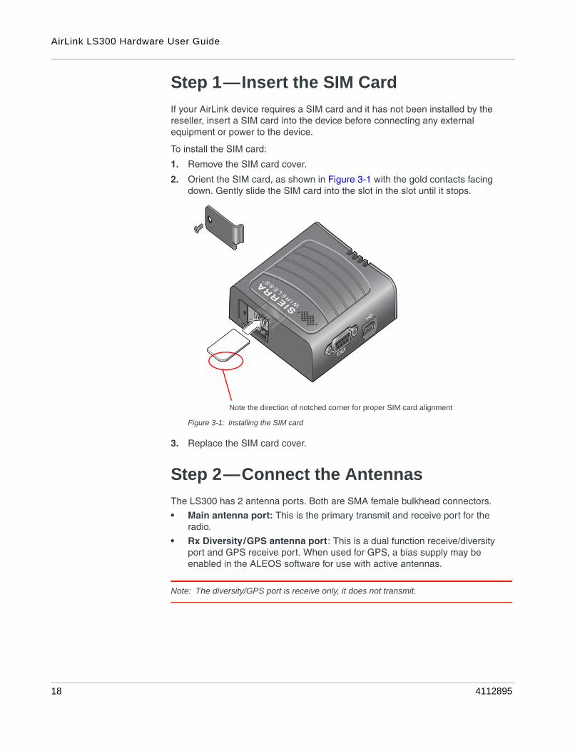
Step 1—Insert the SIM Card
If your AirLink device requires a SIM card and it has not been installed by the reseller, insert a SIM card into the device before connecting any external equipment or power to the device.
To install the SIM card:
1. Remove the SIM card cover.
2. Orient the SIM card, as shown in Figure 3-1 with the gold contacts facing down. Gently slide the SIM card into the slot in the slot until it stops.
Figure 3-1: Installing the SIM card
3. Replace the SIM card cover.
Step 2—Connect the Antennas
The LS300 has 2 antenna ports. Both are SMA female bulkhead connectors.
• Main antenna port: This is the primary transmit and receive port for the radio.
• Rx Diversity/GPS antenna port: This is a dual function receive/diversity port and GPS receive port. When used for GPS, a bias supply may be enabled in the ALEOS software for use with active antennas.
Note: The diversity/GPS port is receive only, it does not transmit.
Note the direction of notched corner for proper SIM card alignment
18 4112895
Installation and Startup
Note: The antenna should not exceed the maximum gain specified in RF Exposure on page 45. In more complex installations (such as those requiring long lengths of cable and/or multiple connections), you must follow the maximum dBi gain guidelines specified by the radio communications regulations of the Federal Communications Commission (FCC) or Industry Canada or your country’s regulatory body (if used outside the US)
To install the antennas:
1. Connect the RF antenna to the SMA antenna connector.
Mount the RF antenna so there is at least 20 cm between the antenna and the user or by-stander.
2. If used, connect either a GPS antenna or a diversity RF antenna to the SMA GPS/Diversity antenna connector.
Take extra care when attaching the antenna to the SMA connectors. Finger tight (approximately 5–7 in-lb.) is sufficient and the max torque should not go beyond 10 in-lb. (1.1 N-m).
Mount the GPS antenna where it has a good view of the sky (at least 90⁰).
3. Connect the antenna cable to the GPS/Diversity antenna connector.
Note: If the antenna is located away from the device, keep the cables as short as possible to prevent the loss of antenna gain. Route the cables so that they are protected from damage and will not be snagged or pulled on. There should be no binding or sharp corners in the cable routing. Excess cabling should be bundled and tied off. Make sure that the cables are secured so that their weight will not loosen the connector from the device over time.
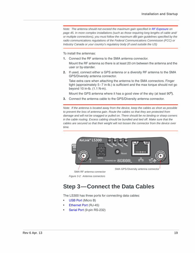
Figure 3-2: Antenna connectors
Step 3—Connect the Data Cables
The LS300 has three ports for connecting data cables:
• USB Port (Micro B)
• Ethernet Port (RJ-45)
• Serial Port (9-pin RS-232)
SMA RF antenna connectorSMA GPS/Diversity antenna connector
Rev 6 Apr. 13 19
AirLink LS300 Hardware User Guide
USB Port
Warning: Do not use the USB port in a potentially explosive environment.
• Complies with USB Version 2.0 for high speed operation
• Can be dynamically configured to operate in one of two modes:
• Virtual Ethernet Port: The LS300 behaves as if the PC were connected to an Ethernet port, allowing access to the Internet and the LS300’s internal web server. This is the default setting.
• Virtual Serial Port : The LS300 behaves as if it was connected to a standard serial port. The primary use of this interface is for the AT command line interface of ALEOS and for diagnostic access to the radio module.
Note: By default, the USB port is configured as a virtual Ethernet port.
A Windows driver must be installed on the PC in order to support USB use. The drivers are available for download at source.sierrawireless.com.
The ALEOS Software Configuration User Guide contains the details of USB mode configuration and driver installation.
We recommend you:
• Use a USB 2.0 cable
• Connect directly to your computer for best throughput.
Ethernet Port
• IEEE 802.3 specification for 100 Mbps speed (Fast Ethernet) with fallback to 10 Mbps
• Auto-crossover support
• Auto-sensing detects the speed of the connecting device for 100 baseT or 10 baseT
Serial Port
• 9-pin serial port connects directly to most computers or other devices with a standard serial straight-through cable
Note: If you have a DCE device, you need to use a null modem (cross-over) cable.
• Used for device configuration and debugging.
• Complies with the EIA RS-232D specification for DCE equipment
• Output driver levels swing from -7 VDC to +7 VDC with normal loading
20 4112895
Installation and Startup
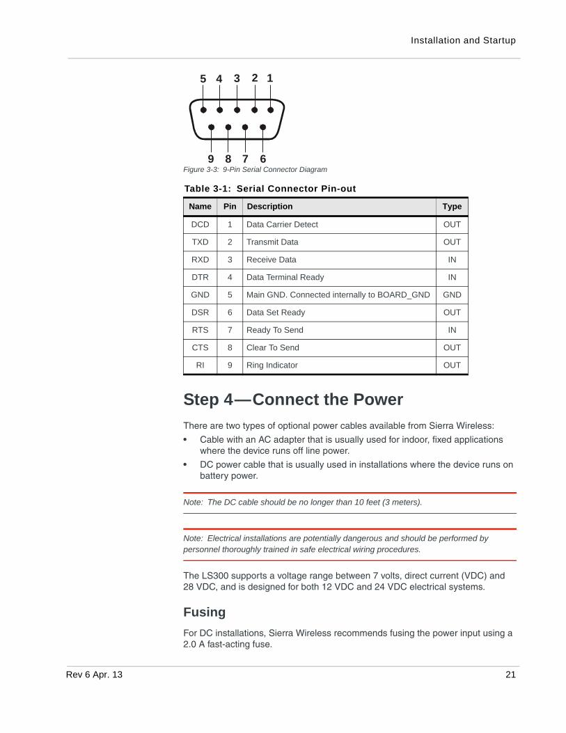
Figure 3-3: 9-Pin Serial Connector Diagram
Step 4—Connect the Power
There are two types of optional power cables available from Sierra Wireless:
• Cable with an AC adapter that is usually used for indoor, fixed applications where the device runs off line power.
• DC power cable that is usually used in installations where the device runs on battery power.
Note: The DC cable should be no longer than 10 feet (3 meters).
Note: Electrical installations are potentially dangerous and should be performed by personnel thoroughly trained in safe electrical wiring procedures.
The LS300 supports a voltage range between 7 volts, direct current (VDC) and 28 VDC, and is designed for both 12 VDC and 24 VDC electrical systems.
Fusing
For DC installations, Sierra Wireless recommends fusing the power input using a 2.0 A fast-acting fuse.
Table 3-1: Serial Connector Pin-out
Name Pin Description Type
DCD 1 Data Carrier Detect OUT
TXD 2 Transmit Data OUT
RXD 3 Receive Data IN
DTR 4 Data Terminal Ready IN
GND 5 Main GND. Connected internally to BOARD_GND GND
DSR 6 Data Set Ready OUT
RTS 7 Ready To Send IN
CTS 8 Clear To Send OUT
RI 9 Ring Indicator OUT
12345
6789
Rev 6 Apr. 13 21

AirLink LS300 Hardware User Guide
Power Supply Conditioning
For automotive applications, the supply voltage may momentarily drop below 7 V during engine cranking, causing the LS300 to reboot. If this happens, the LS300 restarts automatically and is ready for use once the reboot is complete. If your application requires the LS300 to continue operating during engine cranking, add external power conditioning circuits to ensure the supply voltage does not drop below the rated value (7.0 V).
Grounding the LS300 Chassis
For DC installations (with a fixed “system” ground reference), Sierra Wireless recommends always grounding the LS300 chassis to this system ground reference. To ensure a good grounding reference, use a short wire with a gauge of 18 AWG or larger connected to one of the mounting screws.
Power Connector on the LS300
If you are using the DC power cable to connect the LS300 to a power source:
• Pin 1 (Power)—Use the red wire in the DC cable to connect Pin 1 to the power source. Include a 2.0 A fast-acting fuse in the input power line. Sierra Wireless recommends using a continuous (unswitched) DC power source. For installations that require the device to be turned on/off, Sierra Wireless recommends using the Ignition Sense (pin 3) input for this purpose.
• Pin 2 (Ground)—Use the black wire in the DC cable to connect Pin 2 to ground. See also Grounding the LS300 Chassis on page 22.
• Pin 3 (Ignition Sense)— Sierra Wireless recommends always using the Ignition Sense wire to turn the gateway off. It should not be turned off by disconnecting power.
For installations that require the LS300 to be turned on/off, use the white wire in the DC cable to connect Pin 3 to:· A vehicle ignition for turning the LS300 on when the ignition is on· A low voltage monitor for turning the LS300 off when the supply voltage
drops below a defined level.
For installations where the LS300 is permanently on (never turned on/off), connect the white wire to the red wire.
Pin 3 can be used as the trigger for the low power mode. For more informa-tion, refer to the ALEOS Software Configuration User Guide (Services chap-ter). If desired, you can also configure the LS300 to notify you when it goes into Low Power mode. For details, refer the ALEOS Software Configuration User Guide (Events Reporting chapter).
Note: Sierra Wireless strongly recommends that you use an unswitched VCC, with Pin 3 (white wire on DC cable) connected to the ignition (if you want the LS300 on when the ignition is on) or connected to a low voltage monitor (if you want the LS300 to turn off when the voltage drops below a defined level). See Figure 3-4 on page 23. This is particularly important for when the input power supply is not constant, such as vehicle installations.
22 4112895

Installation and Startup
• Pin 4 (General Purpose I/O) (Optional)—Use the green wire in the DC cable to connect Pin 4 to a switch or relay on an external device you want to monitor. For more details, see page 24.
See Figure 3-4 and Table 3-2.
Figure 3-4: DC power cable connections (Colors indicate DC cable wire colors.)
GPI/O
Battery
- +
2.0 A fast-acting
Ignition switch or
fuse
Ground
Pin 4
Connect to switch, relayor external device
Pin 3
Pin 2Ground
Ignition Sense
Pin 1PowerOptional:
Green
Red
Black
White low voltage shutdown
Table 3-2: Power Connector Pin and DC cable Wires
Pin Name Associated DC Cable Wire Color
Description Type
1 Power Red Main power supply for device PWR
2 GND Black Main device ground PWR
3 IGN Sense White Ignition Sense: Connected to the vehicle ignition or an external switch, for example on a low voltage shutdown. When the LS300 is connected to a low voltage shutdown, the LS300 is off when this pin is either open-circuit or grounded, and on when this pin is connected to power.
I
4 GPIO Green User configurable digital input/output or analog voltage sensing input. Connect to switch, relay or external device. Maximum rating is 30 V, 150 mA. For more information, see Pin 4 (General Purpose I/O) on page 24 and the ALEOS Software Configuration User Guide.
I/O
Rev 6 Apr. 13 23

AirLink LS300 Hardware User Guide
Pin 4 (General Purpose I/O)
This pin is a digital input/output (green wire on DC cable).
Pin 4 can:
• Monitor digital inputs and outputs
• Drive a relay
• Monitor analog input
It has a maximum rating of 30 V and 50 mA sink current. For information on configuring Pin 4 (Digital Input/Relay Output 1 in ACEmanager) refer to the ALEOS Software Configuration User Guide (I/O Configuration chapter).
You can use Pin 4 in conjunction with events reporting to configure the LS300 to send a report when the state of the monitored device changes, for example when a switch is opened or closed. For more information, refer to the ALEOS Software Configuration User Guide (Events Reporting chapter).
Digital Input
As a digital input, it monitors a switch, using its opening or closing to record events or monitoring external voltages of up to 30VDC. For example, you could use it to measure the voltage on a 24VDC light bulb and have the device react when it turns on.
When the switch, or input voltage is:
• Open (3.3 VDC to 30 VDC) – It is read as a digital input=1
• Closed (0 to 1.2 VDC) – It is read as a digital input=0
Figure 3-5: Digital Input Operation
Digital Output/Relay Output
As a digital output/relay output, it can trigger an alarm, siren, door lock or opens a valve or a switch. Pin 4 is an open collector transistor output normally at 3.3 VDC. When triggered, it is pulled to low.
3.3 V
Contact closedDigital 00 VDC to 1.2 VDC
Contact openDigital 13.3 VDC to 30 VDC
Contact
Ground
51 kinternal pull up
I/O Circuit
Examples: Door opening/closing, valve opening/closing, ignition on/off, tow bar up/down,empty/full container.
AirLink LS300 device
24 4112895
Installation and Startup
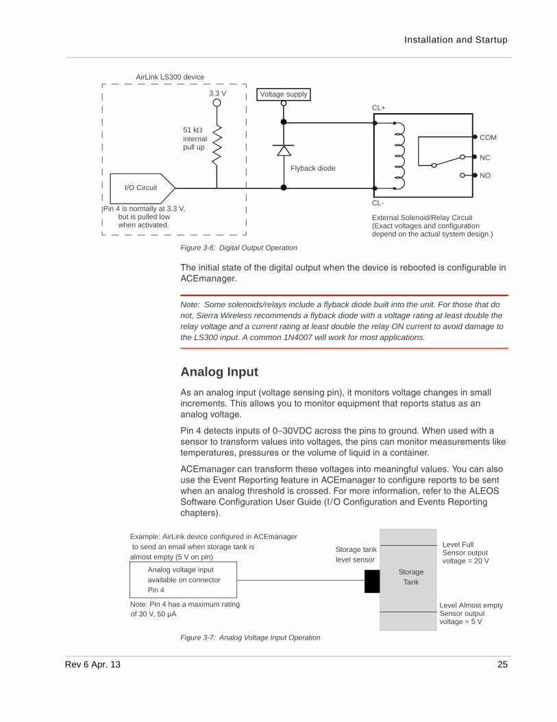
Figure 3-6: Digital Output Operation
The initial state of the digital output when the device is rebooted is configurable in ACEmanager.
Note: Some solenoids/relays include a flyback diode built into the unit. For those that do not, Sierra Wireless recommends a flyback diode with a voltage rating at least double the relay voltage and a current rating at least double the relay ON current to avoid damage to the LS300 input. A common 1N4007 will work for most applications.
Analog Input
As an analog input (voltage sensing pin), it monitors voltage changes in small increments. This allows you to monitor equipment that reports status as an analog voltage.
Pin 4 detects inputs of 0–30VDC across the pins to ground. When used with a sensor to transform values into voltages, the pins can monitor measurements like temperatures, pressures or the volume of liquid in a container.
ACEmanager can transform these voltages into meaningful values. You can also use the Event Reporting feature in ACEmanager to configure reports to be sent when an analog threshold is crossed. For more information, refer to the ALEOS Software Configuration User Guide (I/O Configuration and Events Reporting chapters).
Figure 3-7: Analog Voltage Input Operation
3.3 V
51 kinternal pull up
Voltage supply
CL+
CL-
COM
NC
NO
I/O Circuit
Pin 4 is normally at 3.3 V, but is pulled low External Solenoid/Relay Circuit
(Exact voltages and configurationdepend on the actual system design.)
when activated.
AirLink LS300 device
Flyback diode
Level FullSensor outputvoltage = 20 V
Level Almost emptySensor outputvoltage = 5 V
Storage
Tank
Storage tank
level sensor
Example: AirLink device configured in ACEmanager
to send an email when storage tank is
almost empty (5 V on pin)
Analog voltage input
available on connector
Pin 4
Note: Pin 4 has a maximum ratingof 30 V, 50 µA
Rev 6 Apr. 13 25
AirLink LS300 Hardware User Guide
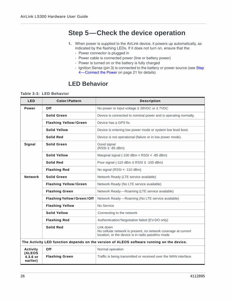
Step 5—Check the device operation
1. When power is supplied to the AirLink device, it powers up automatically, as indicated by the flashing LEDs. If it does not turn on, ensure that the:· Power connector is plugged in· Power cable is connected power (line or battery power)· Power is turned on or the battery is fully charged· Ignition Sense (pin 3) is connected to the battery or power source (see Step
4—Connect the Power on page 21 for details)
LED Behavior
Table 3-3: LED Behavior
LED Color / Pattern Description
Power Off No power or input voltage ≥ 28VDC or ≤ 7VDC
Solid Green Device is connected to nominal power and is operating normally.
Flashing Yellow / Green Device has a GPS fix.
Solid Yellow Device is entering low power mode or system low level boot.
Solid Red Device is not operational (failure or in low power mode).
Signal Solid Green Good signal(RSSI ≥ -85 dBm)
Solid Yellow Marginal signal (-100 dBm < RSSI < -85 dBm)
Solid Red Poor signal (-110 dBm ≤ RSSI ≤ -100 dBm)
Flashing Red No signal (RSSI < -110 dBm)
Network Solid Green Network Ready (LTE service available)
Flashing Yellow / Green Network Ready (No LTE service available)
Flashing Green Network Ready—Roaming (LTE service available)
Flashing Yellow / Green / Off Network Ready—Roaming (No LTE service available)
Flashing Yellow No Service
Solid Yellow Connecting to the network
Flashing Red Authentication/Negotiation failed (EV-DO only)
Solid Red Link downNo cellular network is present, no network coverage at current location, or the device is in radio passthru mode
The Activity LED function depends on the version of ALEOS software running on the device.
Activity(ALEOS 4.3.6 or earlier)
Off Normal operation
Flashing Green Traffic is being transmitted or received over the WAN interface.
26 4112895

Installation and Startup
Ethernet LEDs
The connector has two LEDs that indicate speed and activity. When looking into the connector:
• Activity – The right LED is solid yellow when a link is detected (the cable is plugged in) and blinks when there is activity.
• Connection Speed – The left LED is green to indicate a 100 Mbps link and orange when either no cable is connected or a 10 Mbps link is detected.
Step 6—Startup and Software Configuration
You can configure the ALEOS software on the LS300 using:
• ACEmanager (browser-based application)
• AirLink Management Service (cloud-based application)
• AT Commands
Configuring with ACEmanager
To access ACEmanager:
1. Connect a laptop to the device with an Ethernet cable.
2. Launch your web browser and go to http://192.168.13.31:9191.
Note: It takes the device 2–3 minutes to respond after power up.
Activity(ALEOS 4.4.0 or later)
Off Normal operation
Flashing Green Traffic is being transmitted or received over the WAN interface.
Flashing Red Traffic is being transmitted or received over the serial port. (This behavior only appears if the AirLink LS300 is configured to display it. Refer to the ALEOS Software Configuration Guide for details.)
Flashing Yellow Traffic is being transmitted or received over both the WAN interface and the serial port. (This behavior only appears if the AirLink LS300 is configured to display it. Refer to the ALEOS Software Configuration Guide for details.)
Table 3-3: LED Behavior
LED Color / Pattern Description
Rev 6 Apr. 13 27

AirLink LS300 Hardware User Guide
Figure 3-8: ACEmanager login window
3. Enter the default password, 12345 and click Log in.
4. Refer to the ALEOS Software Configuration User Guide for information on how to use ACEmanager to configure your LS300.
Configuring with AirLink Management Service
AirLink Management Service (ALMS) allows the management of all your devices remotely from one user interface.
Some of its features include:
• Centralized, remote monitoring for all of your AirLink devices.
• Continuous status monitoring of important health data such as signal strength.
• Location monitoring, including world map views.
• Complete ALEOS reporting and configuration, including historical views of ALEOS information.
• Configure individual devices or use templates to perform batch configurations of your AirLink devices.
• Single click over-the-air firmware updates to all your devices.
• Compatible with all carriers or mobile network operators.
To get started either call your AirLink reseller or visit: www.sierrawireless.com/ALMS
Configuring with AT Commands
For a complete list of AT commands, refer to the ALEOS Software Configuration User Guide.
Step 7—Mounting the LS300
Warning: This device is not intended for use close to the human body. Antennas should be at least 8 inches (20 cm) away from the operator.
Mount the device where:
• There is easy access to the cables
• Cables are not bent, constricted, close to high amperages or exposed to extreme temperatures
• The front panel LEDs are easily visible
• There is adequate airflow
• It is away from direct exposure to the elements, such as sun, rain, dust, etc.
• It will not be hit or come into contact with people, cargo, tools, equipment, etc.
28 4112895

Installation and Startup
Mounting Brackets
Sierra Wireless has two mounting bracket kits.
• Mounting Bracket —Screw in for LS300 (P/N 6000571) for use on flat surfaces, including walls or counters.
• DIN Rail Mounting Bracket for LS300 (P/N 6000558)
Flat Surface Mount
If you are mounting the LS300 on a flat surface, order mounting bracket kitP/N 6000571 (Mounting Bracket —Screw in for LS300) from Sierra Wireless. The kit contains:
• Bracket – Qty 1
• Screw M3 – Qty 4
• Screw M4 – Qty 4
Figure 3-9: LS300 Mounting Bracket for flat surfaces
To mount the LS300 on a flat surface using the mounting bracket:
1
1 1
2
22
10 mm (0.39 in.)
106 mm(4.17 in.)
60 mm(2.36 in.)
119 mm(4.68 in.)
89 mm(3.50 in.)
6 mm (0.24 in.)
Top view
Side view
Rev 6 Apr. 13 29

AirLink LS300 Hardware User Guide
1. Line up the LS300 with either set 1 or set 2 holes, depending on the desired orientation. (See Figure 3-9.)
2. Attach the LS300 to the bracket with the three M3 mounting screws. Torque the screws to a maximum of 10 in-lb. (1.1 N-m).
3. Attach the bracket/LS300 combination to the mounting surface.
4. Connect the bracket to ground (the battery or power source negative terminal) by connecting a grounding strap under one of the mounting bracket screws. This provides protection from electrostatic discharges.
DIN Rail Mount
If you are mounting the LS300 on a DIN rail, order mounting bracket kit P/N 6000558 (DIN Rail Mounting Bracket for LS300) from Sierra Wireless. The kit contains:
• L-shaped DIN Rail Mounting Bracket—Qty 1
• DIN Rail Clip (35 mm EN 50022)—Qty 1
• Screw M3—Qty 4
• Screw M4—Qty 4
Figure 3-10: DIN Rail Mounting Bracket
To attach the LS300 to a horizontally mounted DIN rail:
1. Install the SIM card. (See Step 1—Insert the SIM Card on page 18.)
2. Test the network connectivity.
It is important to first ensure network connectivity because once the device is attached to the L-shaped DIN rail mounting bracket, access to the SIM card is restricted.
a. Connect the LS300. Power it up and ensure that you have network connectivity. (See Step 4—Connect the Power on page 21)
Attach LS300 here
Attach the DIN
79.5 mm96 mm
rail clip here
30 4112895

Installation and Startup
3. Place the LS300 on the DIN rail mounting bracket, lining up the mounting holes on the underside of the device with the holes on the DIN rail mounting bracket.
4. Use the M3 screws provided to attach the LS300 to the bracket. Torque the screws to a maximum of 10 in-lb. (1.1 N-m).
5. Use the screws provided to attach the DIN rail clip to the bracket.
6. Attach the DIN rail clip to a horizontal DIN rail, with the spring clip at the bottom, taking into account the location information described in Step 7—Mounting the LS300 on page 28.
Note: The DIN rail bracket and clip in the kit Sierra Wireless provide is not intended for use on DIN rail that is mounted vertically.
Rebooting the LS300
Rebooting resets the LS300, but leaves custom settings intact. To reboot the LS300:
• On the device, press and release the Reset button (1–6 seconds)
• In ACEmanager, click the Reboot button on the toolbar.
Reset the LS300 to factory default settings
To reset the device to the factory default settings:
• On the device, press and hold the Reset button for 7–15 seconds. (Release the button when all the LEDs turn yellowish-green.) If you hold the button down for longer than 15 seconds, the device reboots, but does not reset to the factory default settings. The resetting and reboot cycle takes about 2 minutes to complete. Once the LEDs resume their normal operating behavior, the reset is complete.
• In ACEmanager, go to Admin > Advanced and click the Reset to Factory Default button.
Rev 6 Apr. 13 31
AirLink LS300 Hardware User Guide
32 4112895
Rev 6 Apr.
4
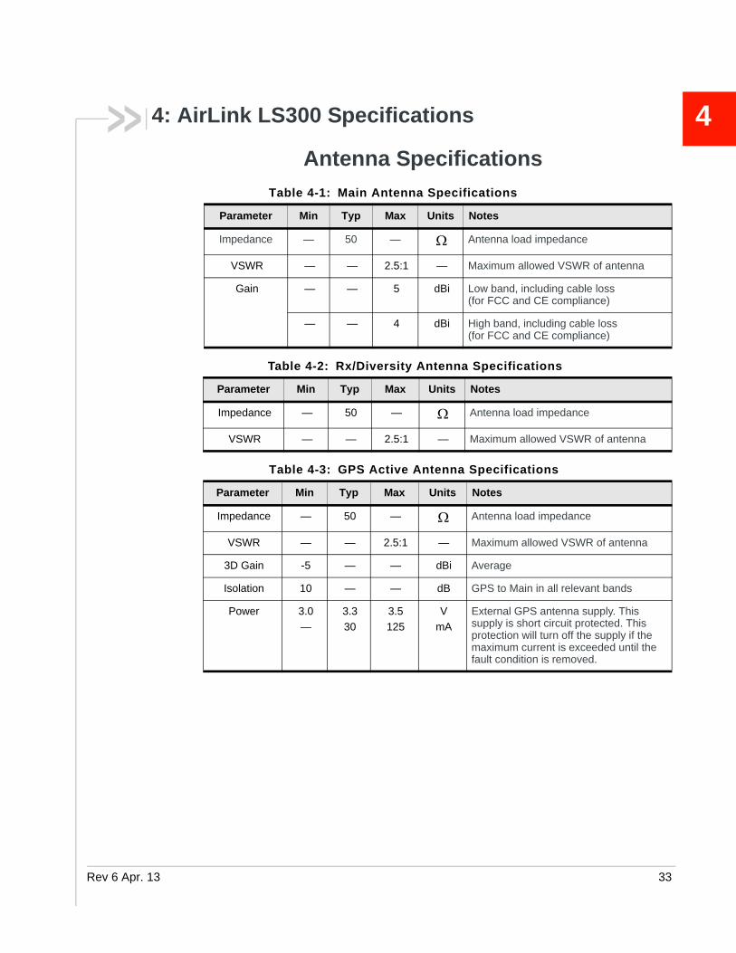
4: AirLink LS300 SpecificationsAntenna Specifications
Table 4-1: Main Antenna Specifications
Parameter Min Typ Max Units Notes
Impedance — 50 — Antenna load impedance
VSWR — — 2.5:1 — Maximum allowed VSWR of antenna
Gain — — 5 dBi Low band, including cable loss (for FCC and CE compliance)
— — 4 dBi High band, including cable loss (for FCC and CE compliance)
Table 4-2: Rx/Diversity Antenna Specifications
Parameter Min Typ Max Units Notes
Impedance — 50 — Antenna load impedance
VSWR — — 2.5:1 — Maximum allowed VSWR of antenna
Table 4-3: GPS Active Antenna Specifications
Parameter Min Typ Max Units Notes
Impedance — 50 — Antenna load impedance
VSWR — — 2.5:1 — Maximum allowed VSWR of antenna
3D Gain -5 — — dBi Average
Isolation 10 — — dB GPS to Main in all relevant bands
Power 3.0
—
3.3
30
3.5
125
V
mA
External GPS antenna supply. This supply is short circuit protected. This protection will turn off the supply if the maximum current is exceeded until the fault condition is removed.
13 33

AirLink LS300 Hardware User Guide
RF Specifications
Frequency Bands
Table 4-4: CDMA Frequency Bands
Band Parameter Frequency
BC0
(US Cellular)
Tx frequency band 824 – 849 MHz
Rx frequency band 869 – 894 MHz
Radio performance Class III
BC1
(US PCS)
Tx frequency band 1850 – 1910 MHz
Rx frequency band 1930 – 1990 MHz
Radio performance Class II
Table 4-5: HSPA North American Frequency Bands
Band Parameter Frequency
Band I
WCDMA 2100
Tx frequency band 1920 – 1980 MHz
Rx frequency band 2110 – 2170 MHz
Radio performance Class III
Band II
WCDMA 1900
Tx frequency band 1850 – 1910 MHz
Rx frequency band 1930 – 1990 MHz
Radio performance Class III
Band V
WCDMA 850
Tx frequency band 824 –849 MHz
Rx frequency band 869 –894 MHz
Radio performance Class III
Band VI
WCDMA 800
Tx frequency band 830 –840 MHz
Rx frequency band 875 –885 MHz
Radio performance Class III
Table 4-6: HSPA International Frequency Bands
Band Parameter Frequency
Band I
WCDMA 2100
Tx frequency band 1920 – 1980 MHz
Rx frequency band 2110 – 2170 MHz
Radio performance Class III
34 4112895

AirLink LS300 Specifications
Radio Module Conducted Transmit Power
The following tables provide radio module conducted transmit power specifications. The radio module type is printed on the label on the bottom of the gateway and is available in ACEmanager (Status > About).
Band VIII WCDMA 900
Tx frequency band 880 – 915 MHz
Rx frequency band 925 – 960 MHz
Radio performance Class III
Table 4-7: GSM/GPRS/EGPRS Frequency Bands
Band Parameter Frequency
GSM 850 Tx frequency band 824 – 849 MHz
Rx frequency band 869 – 894 MHz
Radio performance GPRS Class 4 EGPRS Class E2
GSM 900 Tx frequency band 880 – 915 MHz
Rx frequency band 925 – 960 MHz
Radio performance GPRS Class 4 EGPRS Class E2
GSM 1800 Tx frequency band 1710 – 1785 MHz
Rx frequency band 1805 – 1880 MHz
Radio performance GPRS Class 1 EGPRS Class E2
GSM 1900 Tx frequency band 1850 – 1910 MHz
Rx frequency band 1930 – 1990 MHz
Radio performance GPRS Class 1 EGPRS Class E2
Table 4-8: Verizon Wireless and Sprint Conducted Transmit Power
(Radio Module SL5011a)
a. You can view the Radio Module Type in ACEmanager (Status > About).
Technology Conducted Tx Power (dBm)
IS-95IS-20001xEV-DO, Rev. 01XEV-DO, Rev. A
+24±1
Table 4-6: HSPA International Frequency Bands (Continued)
Band Parameter Frequency
Rev 6 Apr. 13 35
AirLink LS300 Hardware User Guide
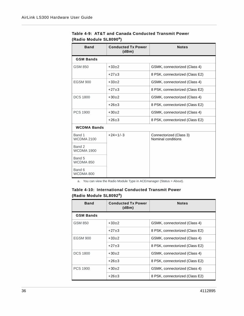
Table 4-9: AT&T and Canada Conducted Transmit Power
(Radio Module SL8090a)
Band Conducted Tx Power (dBm)
Notes
GSM Bands
GSM 850 +33±2 GSMK, connectorized (Class 4)
+27±3 8 PSK, connectorized (Class E2)
EGSM 900 +33±2 GSMK, connectorized (Class 4)
+27±3 8 PSK, connectorized (Class E2)
DCS 1800 +30±2 GSMK, connectorized (Class 4)
+26±3 8 PSK, connectorized (Class E2)
PCS 1900 +30±2 GSMK, connectorized (Class 4)
+26±3 8 PSK, connectorized (Class E2)
WCDMA Bands
Band 1WCDMA 2100
+24+1/-3 Connectorized (Class 3)Nominal conditions
Band 2WCDMA 1900
Band 5WCDMA 850
Band 6WCDMA 800
a. You can view the Radio Module Type in ACEmanager (Status > About).
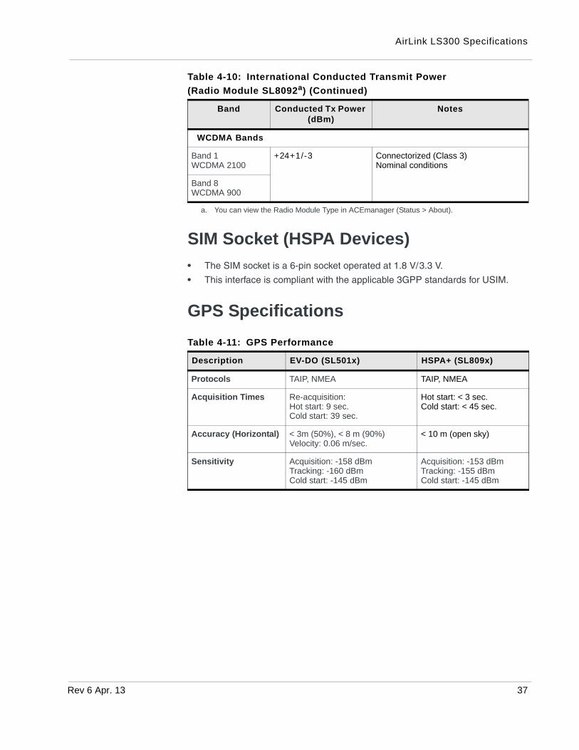
Table 4-10: International Conducted Transmit Power
(Radio Module SL8092a)
Band Conducted Tx Power (dBm)
Notes
GSM Bands
GSM 850 +33±2 GSMK, connectorized (Class 4)
+27±3 8 PSK, connectorized (Class E2)
EGSM 900 +33±2 GSMK, connectorized (Class 4)
+27±3 8 PSK, connectorized (Class E2)
DCS 1800 +30±2 GSMK, connectorized (Class 4)
+26±3 8 PSK, connectorized (Class E2)
PCS 1900 +30±2 GSMK, connectorized (Class 4)
+26±3 8 PSK, connectorized (Class E2)
36 4112895
AirLink LS300 Specifications
SIM Socket (HSPA Devices)
• The SIM socket is a 6-pin socket operated at 1.8 V/3.3 V.
• This interface is compliant with the applicable 3GPP standards for USIM.
GPS Specifications
WCDMA Bands
Band 1WCDMA 2100
+24+1/-3 Connectorized (Class 3)Nominal conditions
Band 8WCDMA 900
a. You can view the Radio Module Type in ACEmanager (Status > About).
Table 4-11: GPS Performance
Description EV-DO (SL501x) HSPA+ (SL809x)
Protocols TAIP, NMEA TAIP, NMEA
Acquisition Times Re-acquisition: Hot start: 9 sec.Cold start: 39 sec.
Hot start: < 3 sec.Cold start: < 45 sec.
Accuracy (Horizontal) < 3m (50%), < 8 m (90%)Velocity: 0.06 m/sec.
< 10 m (open sky)
Sensitivity Acquisition: -158 dBmTracking: -160 dBmCold start: -145 dBm
Acquisition: -153 dBmTracking: -155 dBmCold start: -145 dBm
Table 4-10: International Conducted Transmit Power
(Radio Module SL8092a) (Continued)
Band Conducted Tx Power (dBm)
Notes
Rev 6 Apr. 13 37
AirLink LS300 Hardware User Guide
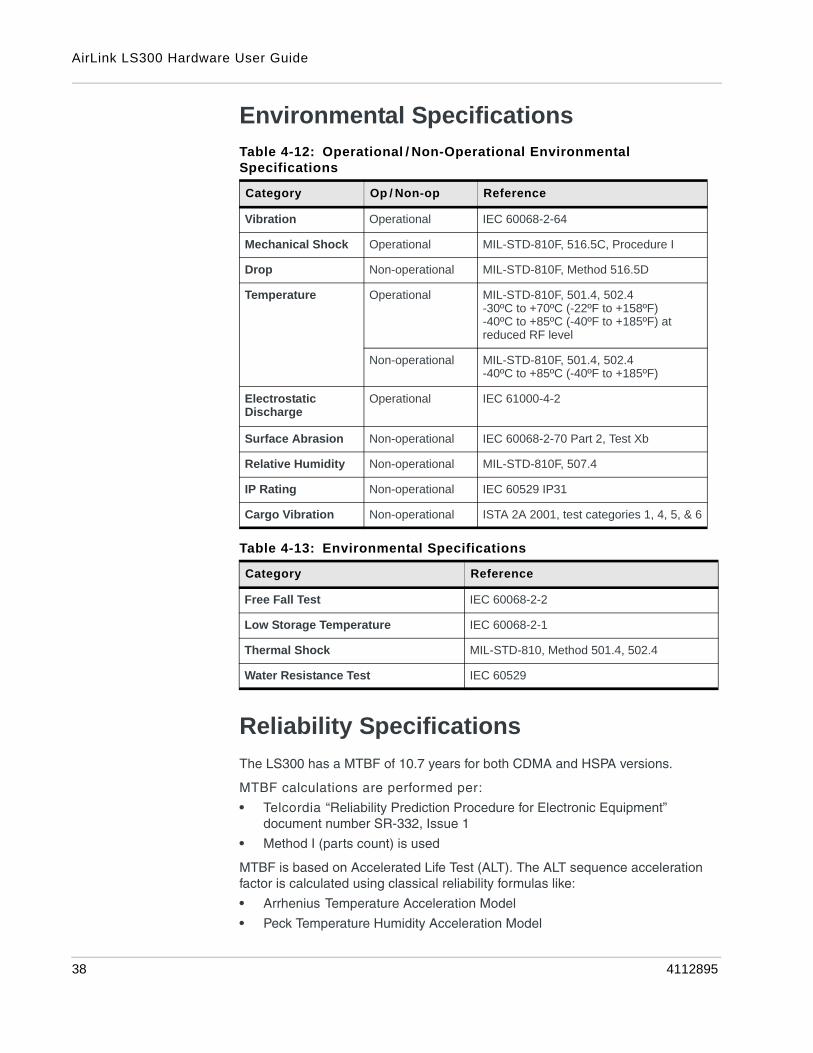
Environmental Specifications
Reliability Specifications
The LS300 has a MTBF of 10.7 years for both CDMA and HSPA versions.
MTBF calculations are performed per:
• Telcordia “Reliability Prediction Procedure for Electronic Equipment” document number SR-332, Issue 1
• Method I (parts count) is used
MTBF is based on Accelerated Life Test (ALT). The ALT sequence acceleration factor is calculated using classical reliability formulas like:
• Arrhenius Temperature Acceleration Model
• Peck Temperature Humidity Acceleration Model
Table 4-12: Operational / Non-Operational Environmental Specifications
Category Op / Non-op Reference
Vibration Operational IEC 60068-2-64
Mechanical Shock Operational MIL-STD-810F, 516.5C, Procedure I
Drop Non-operational MIL-STD-810F, Method 516.5D
Temperature Operational MIL-STD-810F, 501.4, 502.4-30ºC to +70ºC (-22ºF to +158ºF)-40ºC to +85ºC (-40ºF to +185ºF) at reduced RF level
Non-operational MIL-STD-810F, 501.4, 502.4-40ºC to +85ºC (-40ºF to +185ºF)
Electrostatic Discharge
Operational IEC 61000-4-2
Surface Abrasion Non-operational IEC 60068-2-70 Part 2, Test Xb
Relative Humidity Non-operational MIL-STD-810F, 507.4
IP Rating Non-operational IEC 60529 IP31
Cargo Vibration Non-operational ISTA 2A 2001, test categories 1, 4, 5, & 6
Table 4-13: Environmental Specifications
Category Reference
Free Fall Test IEC 60068-2-2
Low Storage Temperature IEC 60068-2-1
Thermal Shock MIL-STD-810, Method 501.4, 502.4
Water Resistance Test IEC 60529
38 4112895

AirLink LS300 Specifications
• Coffin–Manson Temperature Cycle Acceleration Model
• Power Spectral Density Power Law–Vibration Acceleration Model
Rev 6 Apr. 13 39
AirLink LS300 Hardware User Guide
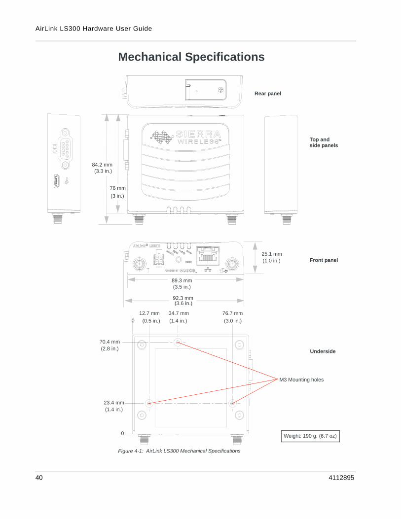
Mechanical Specifications
Figure 4-1: AirLink LS300 Mechanical Specifications
84.2 mm
25.1 mm
89.3 mm
92.3 mm
(3.3 in.)
(3.5 in.)
(3.6 in.)
76 mm
(3 in.)
(1.0 in.)
0
12.7 mm 34.7 mm 76.7 mm
0
23.4 mm
70.4 mm
(1.4 in.)
(2.8 in.)
(0.5 in.) (1.4 in.) (3.0 in.)
Rear panel
Top and side panels
Front panel
Underside
M3 Mounting holes
Weight: 190 g. (6.7 oz)
40 4112895
AirLink LS300 Specifications
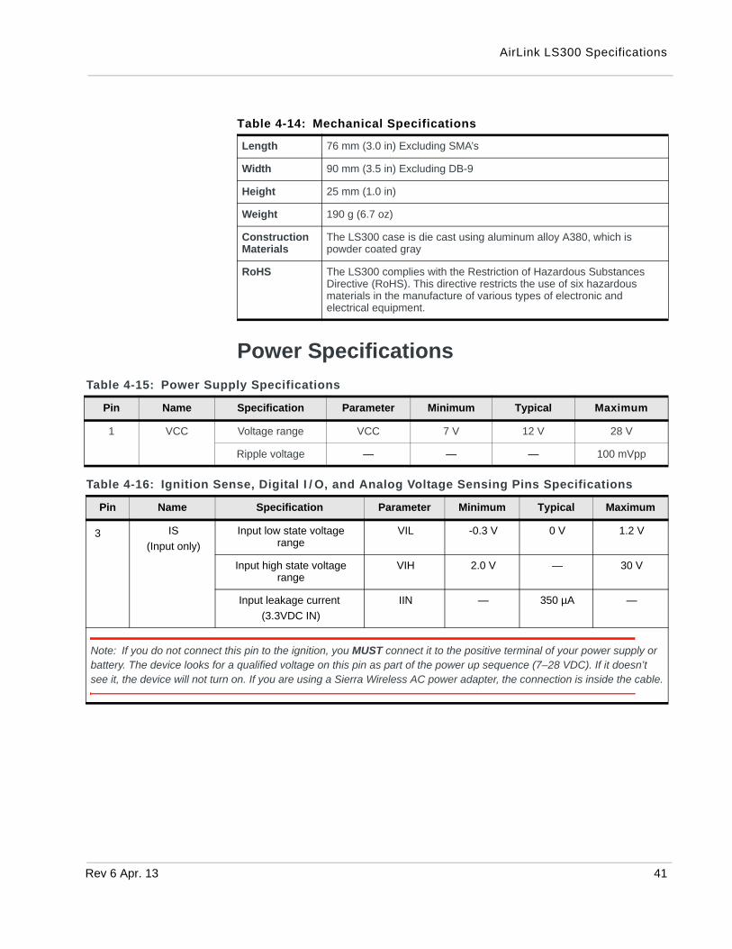
Power Specifications
Table 4-14: Mechanical Specifications
Length 76 mm (3.0 in) Excluding SMA’s
Width 90 mm (3.5 in) Excluding DB-9
Height 25 mm (1.0 in)
Weight 190 g (6.7 oz)
Construction Materials
The LS300 case is die cast using aluminum alloy A380, which is powder coated gray
RoHS The LS300 complies with the Restriction of Hazardous Substances Directive (RoHS). This directive restricts the use of six hazardous materials in the manufacture of various types of electronic and electrical equipment.
Table 4-15: Power Supply Specifications
Pin Name Specification Parameter Minimum Typical Maximum
1 VCC Voltage range VCC 7 V 12 V 28 V
Ripple voltage — — — 100 mVpp
Table 4-16: Ignition Sense, Digital I / O, and Analog Voltage Sensing Pins Specifications
Pin Name Specification Parameter Minimum Typical Maximum
3 IS
(Input only)
Input low state voltage range
VIL -0.3 V 0 V 1.2 V
Input high state voltage range
VIH 2.0 V — 30 V
Input leakage current
(3.3VDC IN)
IIN — 350 µA —
Note: If you do not connect this pin to the ignition, you MUST connect it to the positive terminal of your power supply or battery. The device looks for a qualified voltage on this pin as part of the power up sequence (7–28 VDC). If it doesn’t see it, the device will not turn on. If you are using a Sierra Wireless AC power adapter, the connection is inside the cable.
Rev 6 Apr. 13 41

AirLink LS300 Hardware User Guide
Power Consumption
4 GPIO
(Input)
Input low state voltage range
VIL -0.5 V 0 1.2 V
Input high state voltage range
VIH 1.3 V 3.3 V 30 V
Input leakage current
(3.3VDC IN)
IIN — 58 µA —
Typical application input source is a dry switch contact to ground.
Pin includes an internal 51K pull up to 3.3VDC.
DIGIO
(Output)
Open drain drive to ground Idc — 150 mA 200 mA
Maximum open circuit voltage applied
Voc — 3.3 V 30 V
V @ 200 MA Voh — 0.2 V 0.5 V
Typical application is to drive a relay coil to ground.
Pin includes an internal 51K pull up to 3.3VDC.
This output is not recommended as a current source.
DIGIO (Analog Voltage Input
Only)
Input voltage range VI -0.3 0 30
ADC resolution: 10 bits
Typical application is to monitor an analog voltage.
Table 4-16: Ignition Sense, Digital I / O, and Analog Voltage Sensing Pins Specifications
Pin Name Specification Parameter Minimum Typical Maximum
Table 4-17: Power Consumption (mA @ 12 VDC)
Technology Idle Typical Maximum
HSPA+ 224 mA 245 mA 430 mA
CDMA 220 mA 257 mA 427 mA
Low Power Standby Mode (All models): < 68
Table 4-18: Power Consumption (Watts)
Technology Idle Typical Maximum
HSPA+ 2.6 W 2.8 W 5.0 W
CDMA 2.5 W 3.0 W 5.0 W
42 4112895
AirLink LS300 Specifications
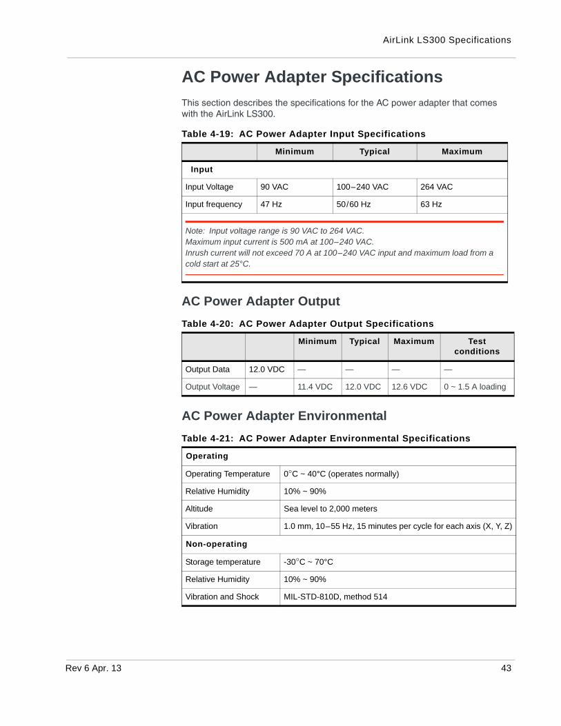
AC Power Adapter Specifications
This section describes the specifications for the AC power adapter that comes with the AirLink LS300.
AC Power Adapter Output
AC Power Adapter Environmental
Table 4-19: AC Power Adapter Input Specifications
Minimum Typical Maximum
Input
Input Voltage 90 VAC 100–240 VAC 264 VAC
Input frequency 47 Hz 50/60 Hz 63 Hz
Note: Input voltage range is 90 VAC to 264 VAC. Maximum input current is 500 mA at 100–240 VAC.Inrush current will not exceed 70 A at 100–240 VAC input and maximum load from a cold start at 25°C.
Table 4-20: AC Power Adapter Output Specifications
Minimum Typical Maximum Test conditions
Output Data 12.0 VDC — — — —
Output Voltage — 11.4 VDC 12.0 VDC 12.6 VDC 0 ~ 1.5 A loading
Table 4-21: AC Power Adapter Environmental Specifications
Operating
Operating Temperature 0°C ~ 40°C (operates normally)
Relative Humidity 10% ~ 90%
Altitude Sea level to 2,000 meters
Vibration 1.0 mm, 10–55 Hz, 15 minutes per cycle for each axis (X, Y, Z)
Non-operating
Storage temperature -30°C ~ 70°C
Relative Humidity 10% ~ 90%
Vibration and Shock MIL-STD-810D, method 514
Rev 6 Apr. 13 43

AirLink LS300 Hardware User Guide
AC Power Adapter Reliability and Quality Control
MTBF
When the power supply is operating within the limits of this specification, the MTBF is at least 50,000 hours at 25°C (MIL-HDBK-217F).
AC Power Adapter Safety Standards
The power supply is certified with the following international regulatory standards:
AC Power Adapter EMC Standards
The power supply meets the radiated and conducted emission requirements for EN55022, FCC Part 15, Class B, GB9254.
AC Power Adapter Hazardous Substances
• EU Directive 2011/65/EU “RoHS”
• EU Directive 2002/96/EC “WEEE”
• REACH
AC Power Adapter Energy Efficiency
• No-load power consumption is less than 0.3 W at input 115/230 VAC 60/50 Hz.
• Average active mode efficiency is greater than 80.4% at input 115/230 VAC 60/50 Hz.
• International Efficiency Level V
• Energy Star Energy Efficiency requirements for external power supplies (EPS Version 2)
• Canada’s Energy Efficiency Regulations for external power supplies
Regulatory Agency
Country or Region
Certified Standard
UL USA Approved UL60950-1
GS Europe Approved EN60950-1
CE Europe Approved EN60950-1
SAA Australia Approved AS/NZS 60950
CCC China Approved GB4943
CUL Canada Approved CSA C22.2 NO.60950-1
44 4112895

Rev 6 May
5
5: Regulatory InformationImportant Information for North American Users
Note: This equipment has been tested and found to comply with the limits for a Class A digital device, pursuant to part 15 of the FCC Rules. These limits are designed to provide reasonable protection against harmful interference when the equipment is operated in a commercial environment. This equipment generates, uses, and can radiate radio frequency energy and, if not installed and used in accordance with the instruction manual, may cause harmful interference to radio communications. Operation of this equipment in a residential area is likely to cause harmful interference, in which case the user will be required to correct the interference at his own expense.
Warning: Changes or modifications to this device not expressly approved by Sierra Wireless could void the user's authority to operate this equipment.
RF Exposure
In accordance with FCC/IC requirements of human exposure to radio frequency fields, the radiating element shall be installed such that a minimum separation distance of 20 cm should be maintained from the antenna and the user's body.
Warning: This product is only to be installed by qualified personnel!
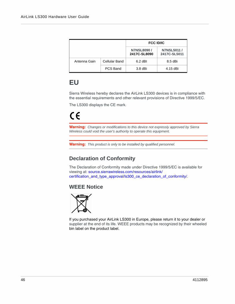
To comply with FCC/IC regulations limiting both maximum RF output power and human exposure to RF radiation, the maximum antenna gain must not exceed the specifications listed below for the device used.
.15 45
AirLink LS300 Hardware User Guide
EU
Sierra Wireless hereby declares the AirLink LS300 devices is in compliance with the essential requirements and other relevant provisions of Directive 1999/5/EC.
The LS300 displays the CE mark.
Warning: Changes or modifications to this device not expressly approved by Sierra Wireless could void the user's authority to operate this equipment.
Warning: This product is only to be installed by qualified personnel.
Declaration of Conformity
The Declaration of Conformity made under Directive 1999/5/EC is available for viewing at: source.sierrawireless.com/resources/airlink/certification_and_type_approval/ls300_ce_declaration_of_conformity/.
WEEE Notice
If you purchased your AirLink LS300 in Europe, please return it to your dealer or supplier at the end of its life. WEEE products may be recognized by their wheeled bin label on the product label.
FCC ID/IC
N7NSL8090 / 2417C-SL8090
N7NSL5011 / 2417C-SL5011
Antenna Gain Cellular Band 6.2 dBI 8.5 dBi
PCS Band 3.8 dBi 4.15 dBi
46 4112895

Rev 6 Ma
6
6: AcronymsTable F-1: Acronyms
Acronym or term Definition
1xEV-DO Single Carrier (1X) EVolution–Data Only
A high-speed standard for cellular packet data communications. It supports Internet connections with data rates up to 3.1 Mbps. (downlink from the network) and 1.8 Mbps (uplink to the network). Average data rates are approximately: Rev. A: 600-1300 kbps. (downlink from the network) and 300-400 kbps (uplink to the network)Rev. 0: 400-700 kbps (downlink from the network) and 40-80 kbps (uplink to the network)Actual speed depends on the network conditions. Compare to 1X.
1X Single Carrier (1X) Radio Transmission Technology
A high-speed standard for cellular packet data communications.
1x supports Internet connections with data rates up to 153 kbps (simultaneously in each direction—downlink and uplink). Actual speed depends on the network conditions. Compare to 1xEV-DO.
3GPP 3rd Generation Partnership Project
3GPP unites 6 telecommunications standard development organizations (ARIB, ATIS, CCSA, ETSI, TTA, TTC), and provides their members with a stable environment to produce Reports and Specifications that define 3GPP technologies.
AT A set of device commands, preceded by “AT” originally developed by Hayes, Inc. for their devices.
The structure (but not the specific commands, which vary greatly from manufacturer to manufacturer) is a de facto device industry standard.
CDMA Code Division Multiple Access
A wideband spread spectrum technique used in digital cellular, personal communications services, and other wireless networks.
Wide channels (1.25 MHz) are obtained through spread spectrum transmissions, thus allowing many active users to share the same channel. Each user is assigned a unique digital code, which differentiates the individual conversations on the same channel.
cdmaOne A IS-95 CDMA standard developed by QUALCOMM Inc.
Also known as TIA-EIA-95
CE, CE label The CE label is a mandatory conformity marking for products placed on the market in the European Economic Area (EEA).
With the CE marking on a product, the manufacturer declares that the product conforms with the essential requirements of the applicable EC directives.
y.15 47
AirLink LS300 Hardware User Guide
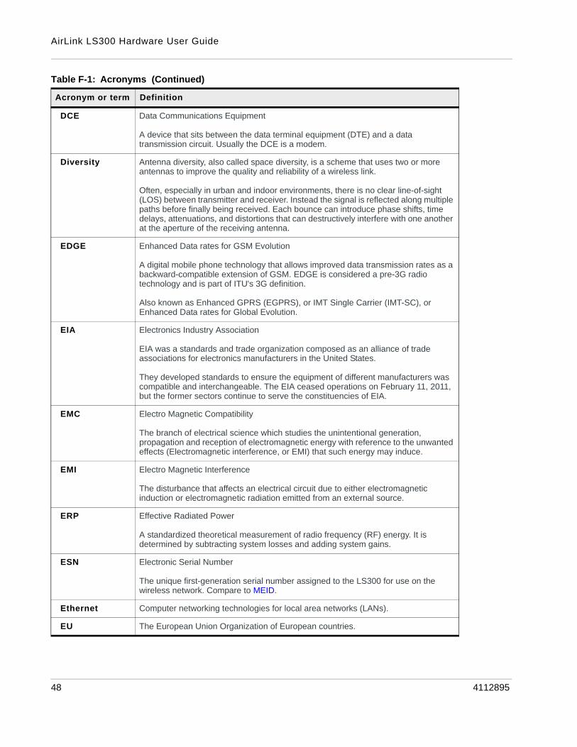
DCE Data Communications Equipment
A device that sits between the data terminal equipment (DTE) and a data transmission circuit. Usually the DCE is a modem.
Diversity Antenna diversity, also called space diversity, is a scheme that uses two or more antennas to improve the quality and reliability of a wireless link.
Often, especially in urban and indoor environments, there is no clear line-of-sight (LOS) between transmitter and receiver. Instead the signal is reflected along multiple paths before finally being received. Each bounce can introduce phase shifts, time delays, attenuations, and distortions that can destructively interfere with one another at the aperture of the receiving antenna.
EDGE Enhanced Data rates for GSM Evolution
A digital mobile phone technology that allows improved data transmission rates as a backward-compatible extension of GSM. EDGE is considered a pre-3G radio technology and is part of ITU's 3G definition.
Also known as Enhanced GPRS (EGPRS), or IMT Single Carrier (IMT-SC), or Enhanced Data rates for Global Evolution.
EIA Electronics Industry Association
EIA was a standards and trade organization composed as an alliance of trade associations for electronics manufacturers in the United States.
They developed standards to ensure the equipment of different manufacturers was compatible and interchangeable. The EIA ceased operations on February 11, 2011, but the former sectors continue to serve the constituencies of EIA.
EMC Electro Magnetic Compatibility
The branch of electrical science which studies the unintentional generation, propagation and reception of electromagnetic energy with reference to the unwanted effects (Electromagnetic interference, or EMI) that such energy may induce.
EMI Electro Magnetic Interference
The disturbance that affects an electrical circuit due to either electromagnetic induction or electromagnetic radiation emitted from an external source.
ERP Effective Radiated Power
A standardized theoretical measurement of radio frequency (RF) energy. It is determined by subtracting system losses and adding system gains.
ESN Electronic Serial Number
The unique first-generation serial number assigned to the LS300 for use on the wireless network. Compare to MEID.
Ethernet Computer networking technologies for local area networks (LANs).
EU The European Union Organization of European countries.
Table F-1: Acronyms (Continued)
Acronym or term Definition
48 4112895
Acronyms
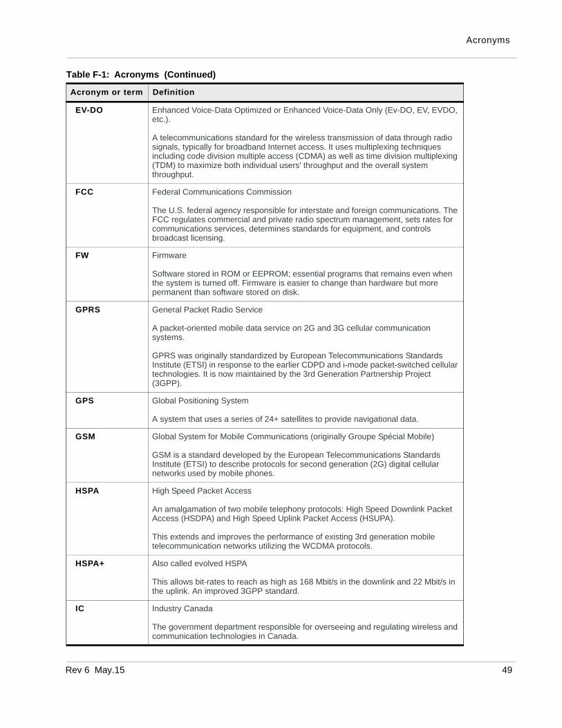
EV-DO Enhanced Voice-Data Optimized or Enhanced Voice-Data Only (Ev-DO, EV, EVDO, etc.).
A telecommunications standard for the wireless transmission of data through radio signals, typically for broadband Internet access. It uses multiplexing techniques including code division multiple access (CDMA) as well as time division multiplexing (TDM) to maximize both individual users' throughput and the overall system throughput.
FCC Federal Communications Commission
The U.S. federal agency responsible for interstate and foreign communications. The FCC regulates commercial and private radio spectrum management, sets rates for communications services, determines standards for equipment, and controls broadcast licensing.
FW Firmware
Software stored in ROM or EEPROM; essential programs that remains even when the system is turned off. Firmware is easier to change than hardware but more permanent than software stored on disk.
GPRS General Packet Radio Service
A packet-oriented mobile data service on 2G and 3G cellular communication systems.
GPRS was originally standardized by European Telecommunications Standards Institute (ETSI) in response to the earlier CDPD and i-mode packet-switched cellular technologies. It is now maintained by the 3rd Generation Partnership Project (3GPP).
GPS Global Positioning System
A system that uses a series of 24+ satellites to provide navigational data.
GSM Global System for Mobile Communications (originally Groupe Spécial Mobile)
GSM is a standard developed by the European Telecommunications Standards Institute (ETSI) to describe protocols for second generation (2G) digital cellular networks used by mobile phones.
HSPA High Speed Packet Access
An amalgamation of two mobile telephony protocols: High Speed Downlink Packet Access (HSDPA) and High Speed Uplink Packet Access (HSUPA).
This extends and improves the performance of existing 3rd generation mobile telecommunication networks utilizing the WCDMA protocols.
HSPA+ Also called evolved HSPA
This allows bit-rates to reach as high as 168 Mbit/s in the downlink and 22 Mbit/s in the uplink. An improved 3GPP standard.
IC Industry Canada
The government department responsible for overseeing and regulating wireless and communication technologies in Canada.
Table F-1: Acronyms (Continued)
Acronym or term Definition
Rev 6 May.15 49
AirLink LS300 Hardware User Guide
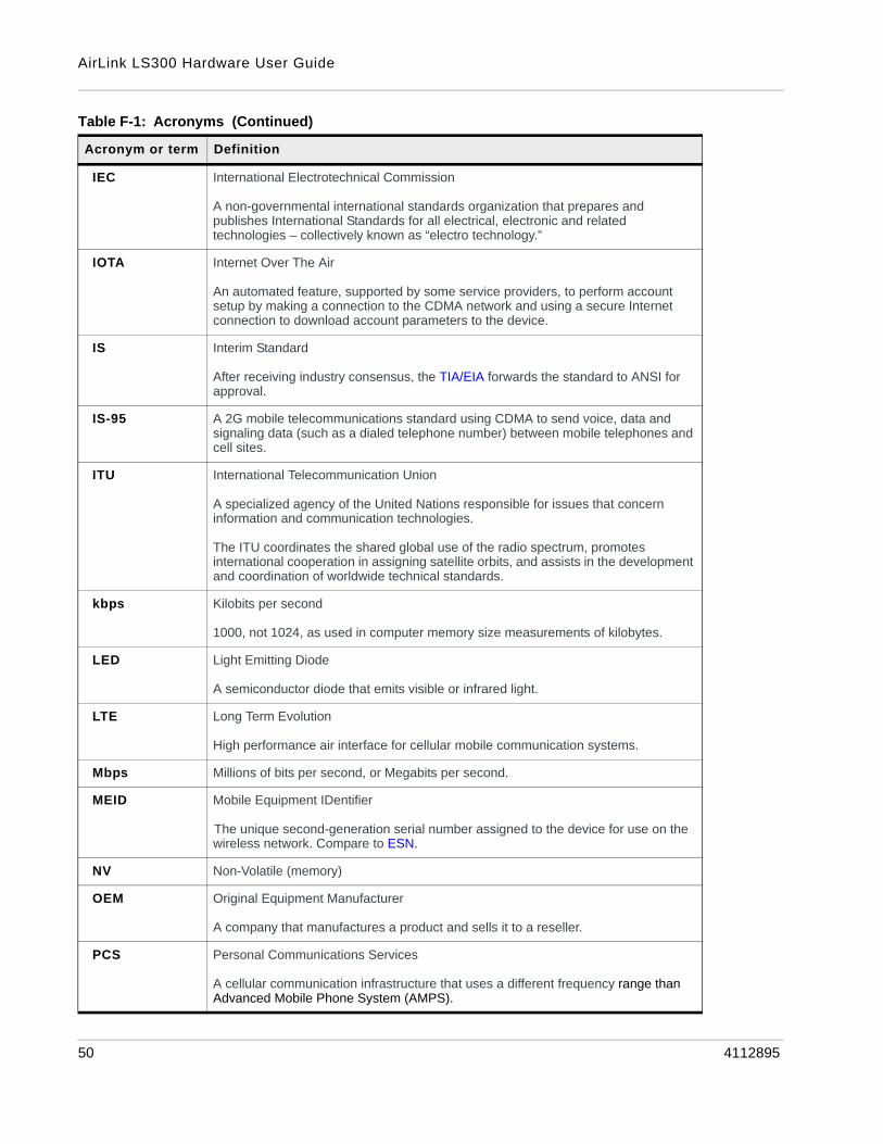
IEC International Electrotechnical Commission
A non-governmental international standards organization that prepares and publishes International Standards for all electrical, electronic and related technologies – collectively known as “electro technology.”
IOTA Internet Over The Air
An automated feature, supported by some service providers, to perform account setup by making a connection to the CDMA network and using a secure Internet connection to download account parameters to the device.
IS Interim Standard
After receiving industry consensus, the TIA/EIA forwards the standard to ANSI for approval.
IS-95 A 2G mobile telecommunications standard using CDMA to send voice, data and signaling data (such as a dialed telephone number) between mobile telephones and cell sites.
ITU International Telecommunication Union
A specialized agency of the United Nations responsible for issues that concern information and communication technologies.
The ITU coordinates the shared global use of the radio spectrum, promotes international cooperation in assigning satellite orbits, and assists in the development and coordination of worldwide technical standards.
kbps Kilobits per second
1000, not 1024, as used in computer memory size measurements of kilobytes.
LED Light Emitting Diode
A semiconductor diode that emits visible or infrared light.
LTE Long Term Evolution
High performance air interface for cellular mobile communication systems.
Mbps Millions of bits per second, or Megabits per second.
MEID Mobile Equipment IDentifier
The unique second-generation serial number assigned to the device for use on the wireless network. Compare to ESN.
NV Non-Volatile (memory)
OEM Original Equipment Manufacturer
A company that manufactures a product and sells it to a reseller.
PCS Personal Communications Services
A cellular communication infrastructure that uses a different frequency range than Advanced Mobile Phone System (AMPS).
Table F-1: Acronyms (Continued)
Acronym or term Definition
50 4112895

Acronyms
PPP Point to Point Protocol
An alternative communications protocol used between computers, or between computers and routers on the Internet. PPP is an enhanced Serial Line Internet Protocol (SLIP).
PRI Product Release Instructions
A file containing the settings used to configure devices for a particular service provider, customer, or purpose.
RF Radio Frequency
RoHS Restriction of use of Hazardous substances mandated by EU Directive 2002/95.
RS-232 A series of standards for serial binary single-ended data and control signals connecting between a DTE (Data Terminal Equipment) and a DCE (Data Circuit-terminating Equipment). It is commonly used in computer serial ports.
Rx Receive
SIM, SIM card Subscriber identity module or subscriber identification module.
An integrated circuit which securely stores the international mobile subscriber identity (IMSI) and the related key used to identify and authenticate subscribers on mobile telephony devices (such as mobile phones and computers).
SKU Stock Keeping Unit
Identifies an inventory item: a unique code, consisting of numbers or letters and numbers, assigned to a product by a retailer for purposes of identification and inventory control.
SLIP Serial Line Internet (or Interface) Protocol
An Internet Protocol designed to work over serial ports and modem connections.
On personal computers, SLIP has been largely replaced by the Point-to-Point Protocol (PPP), which has more features and does not require its IP address configuration to be set before it is established. On microcontrollers SLIP is still the preferred way of encapsulating IP packets due to its very small overhead.
Also see PPP.
SMS Short Message Service
A feature which allows users of a wireless device on a wireless network to receive or transmit short electronic alphanumeric messages (up to 160 characters, depending on the service provider).
TIA/EIA Telecommunications Industry Association / Electronics Industry Association
A standards setting trade organization, whose members provide communications and information technology products, systems, distribution services and professional services in the United States and around the world.
Tx Transmit
Table F-1: Acronyms (Continued)
Acronym or term Definition
Rev 6 May.15 51

AirLink LS300 Hardware User Guide
UMTS Universal Mobile Telecommunications System
A third generation mobile cellular system for networks based on the GSM standard. Developed and maintained by the 3GPP (3rd Generation Partnership Project), UMTS is a component of the International Telecommunications Union IMT-2000 standard set and compares with the CDMA2000 standard set for networks based on the competing cdmaOne technology.
USB Universal Serial Bus
An industry standard defining the cables, connectors and communications protocols used in a bus for connection, communication and power supply between computers and electronic devices.
Table F-1: Acronyms (Continued)
Acronym or term Definition
52 4112895

Rev 6
Index
AAccelerated life test models, 38Accessories, 11Acronyms, 47ALEOS
description of, 11Analog input voltage sensing
on power connector, 24Antenna ports, 33Antenna, safe mounting, 28AT commands, 28
C
Cellular interface, 18Communication
antenna ports, 33AT commands, using, 28cellular radio, 18command line prompt, using, 26
Configuring device, 18Configuring with
AirLink Management Service, 28AT commands, 28
Consumption, power, 37Control interface, 37
D
DC power consumption, 37Description, product, 9Digital I/O specifications, 41Dimensions, of module, 41Diversity antenna, 33
E
Environmental specifications, 38Ethernet
virtual Ethernet port, 20
G
Glossary, 47GPS antenna, 33
I
Interfacecontrol, 37
IP addressobtaining with command line prompt, 26
L
LEDdescription of LED, 26
Length of module, 41
M
Managing device, 18Measuring external voltages, 24Mounting
brackets, 29on DIN rail, 30
mountingDIN rail, 30flat surface, 29
Mounting kits, 30MTBF specifications, 38
N
Non-operational/operational environmental specifica-tions, 38
O
Operational/non-operational environmental specifica-tions, 38
P
Pinging device with command line prompt, 26Ports, 9Power
connector, 21connector, measuring external voltages, 24consumption, 37input specifications, 41power supply specifications, 41
R
Receive/transmit port, 33Regulatory information, 45Regulatory specifications, 44Reliability specifications, 38RF specifications, 18
S
Serial portvirtual serial port, 20
May.15 53
AirLink LS300 Hardware User Guide
Specifications, 33regulatory, 44RF, 18
Standards, regulatory, 44
T
Temperature, operating and non-operating, 38Thickness of module, 41Transmit/receive port, 33
V
Virtual port, Ethernet or serial, 20Voltage
monitoring battery or power input, 24Voltage, input and ripple range, 41
W
Weight of module, 41Width of module, 41
54 4112895


