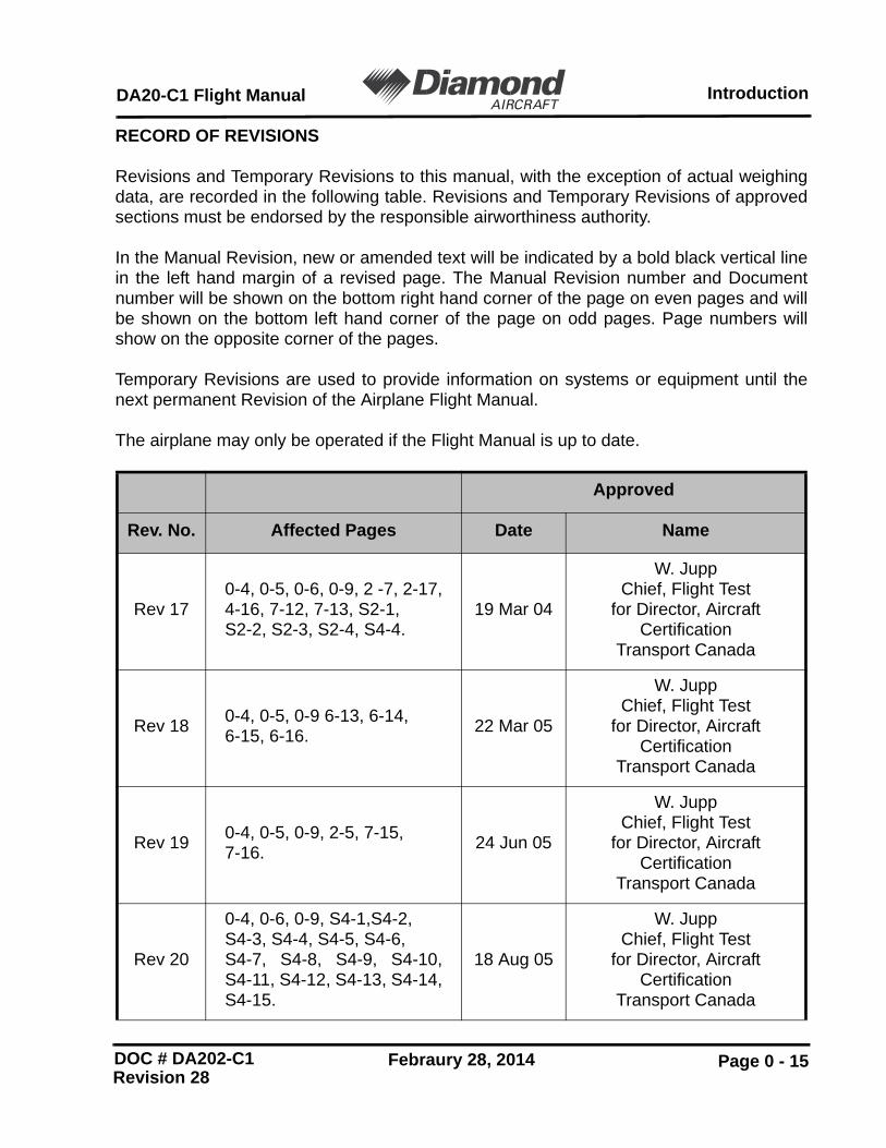
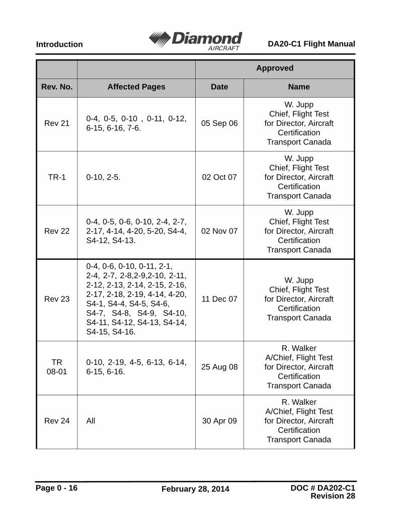
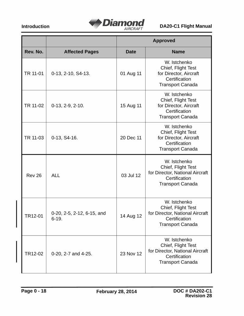
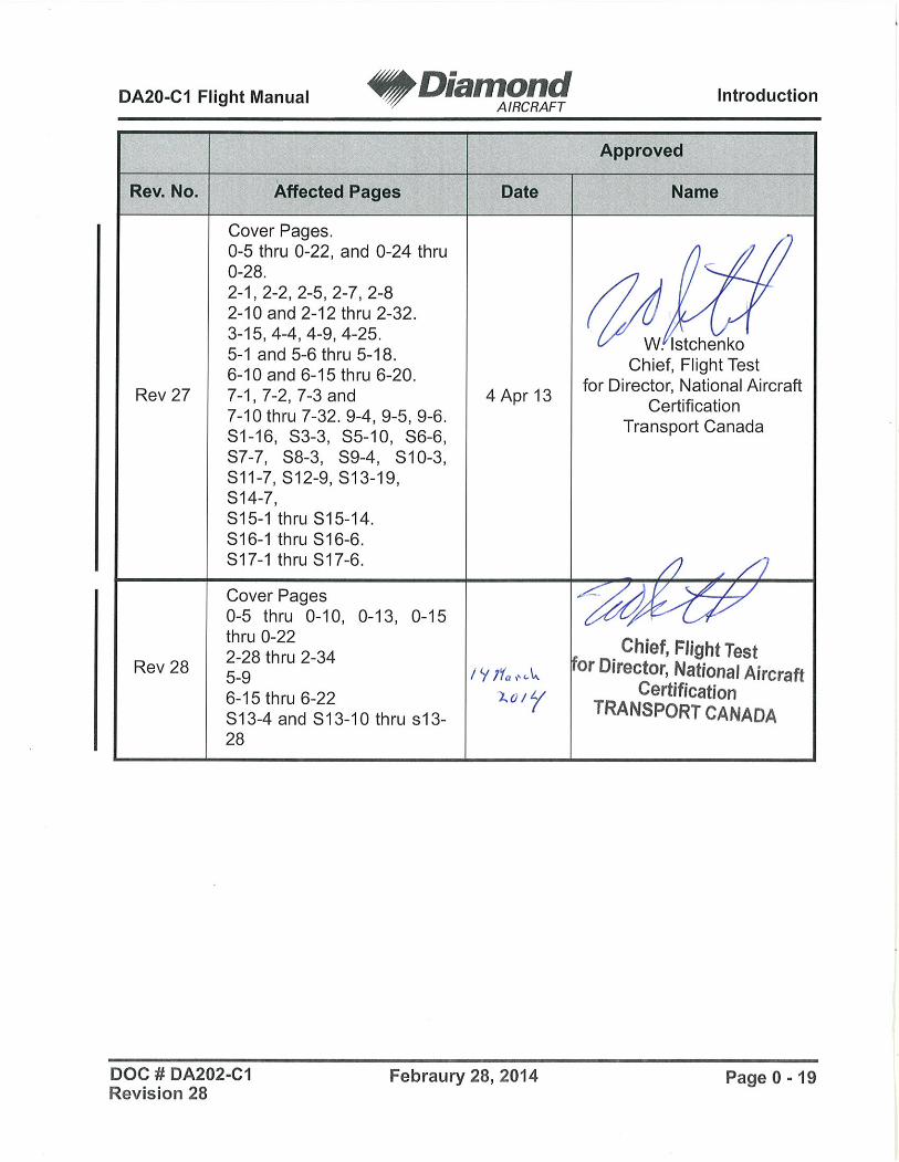
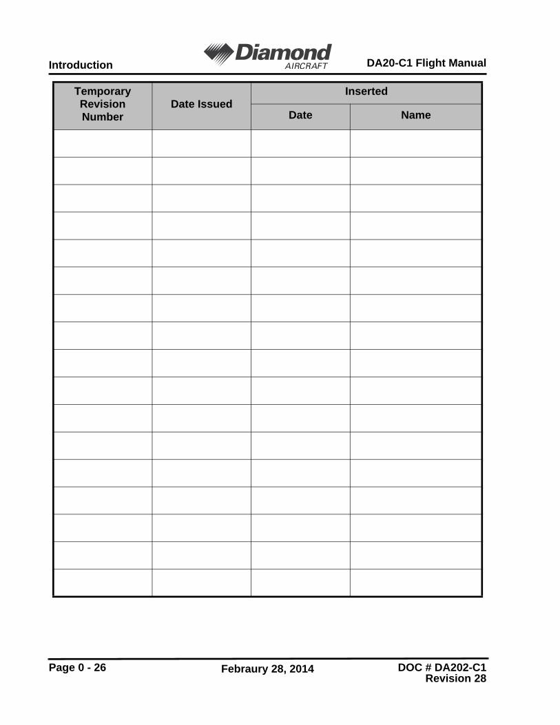
Revisions and Temporary Revisions to this manual, with the exception of actual weighingdata, are recorded in the following table. Revisions and Temporary Revisions of approvedsections must be endorsed by the responsible airworthiness authority.
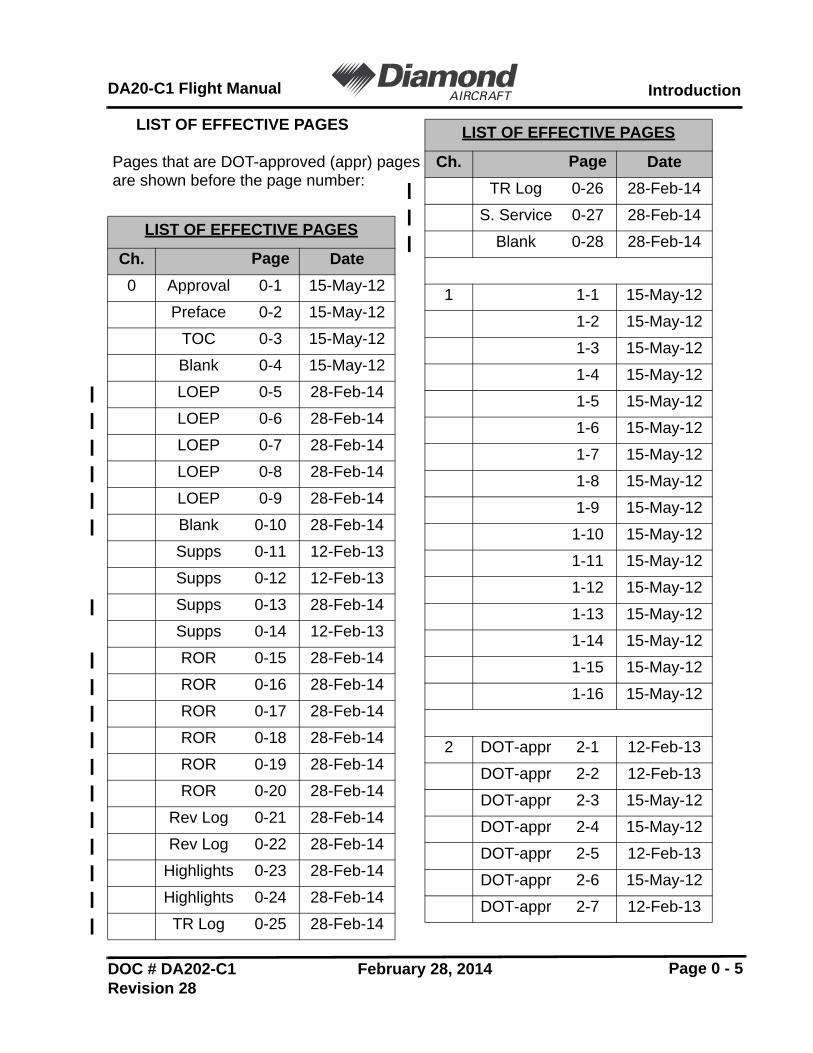
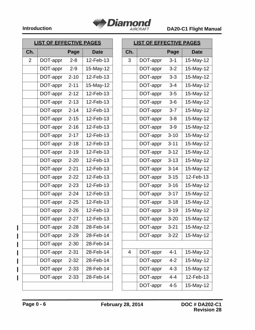
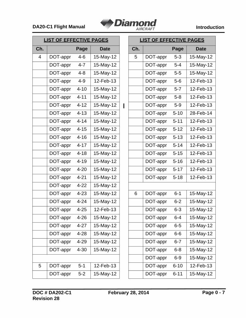
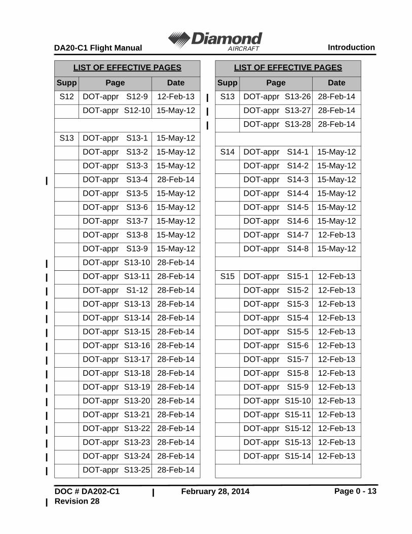
In the Manual Revision, new or amended text will be indicated by a bold black vertical linein the left hand margin of a revised page. The Manual Revision number and Documentnumber will be shown on the bottom right hand corner of the page on even pages and willbe shown on the bottom left hand corner of the page on odd pages. Page numbers willshow on the opposite corner of the pages.
Temporary Revisions are used to provide information on systems or equipment until thenext permanent Revision of the Airplane Flight Manual.
The airplane may only be operated if the Flight Manual is up to date.
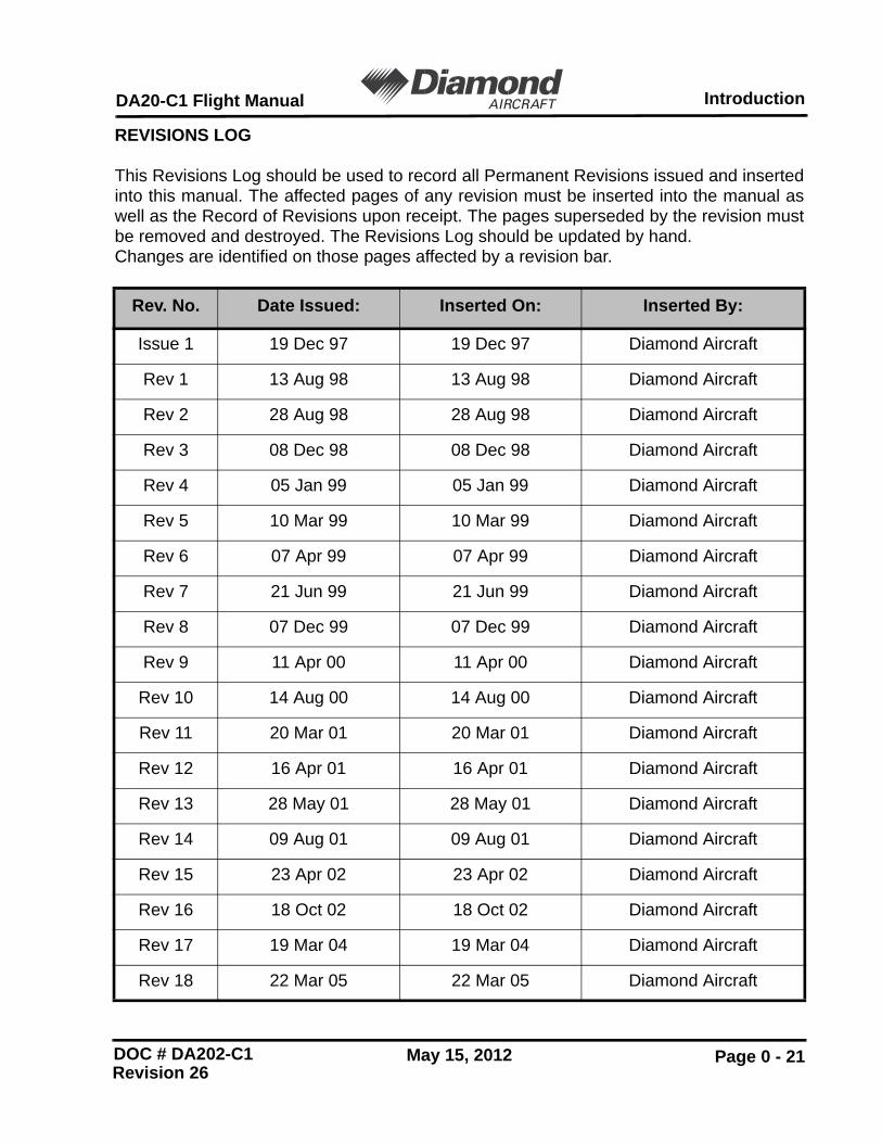
This Revisions Log should be used to record all Permanent Revisions issued and insertedinto this manual. The affected pages of any revision must be inserted into the manual aswell as the Record of Revisions upon receipt. The pages superseded by the revision mustbe removed and destroyed. The Revisions Log should be updated by hand. Changes are identified on those pages affected by a revision bar.
To ensure safe operation and maintenance of the DA20-C1 aircraft, it isrecommended that operators verify that their documentation is at the correctrevision levels. For revision and subscription service please contact the following:
1. DA20-C1 related manuals and publications.
North America, Australia and Africa: Other:
Diamond Aircraft Industries Inc. Diamond Aircraft Industries GmbHCustomer Support Customer Support1560 Crumlin Sideroad N.A. Otto-Strasse 5London, Ontario A-2700 Wiener NeustadtCanada. AustriaN5V 1S2Phone: 519-457-4041 Phone: +43-(0) 2622-26700Fax: 519-457-4060 Fax: +43-(0) 2622-26780
2. Teledyne Continental Motors IO 240B related manuals and publications.
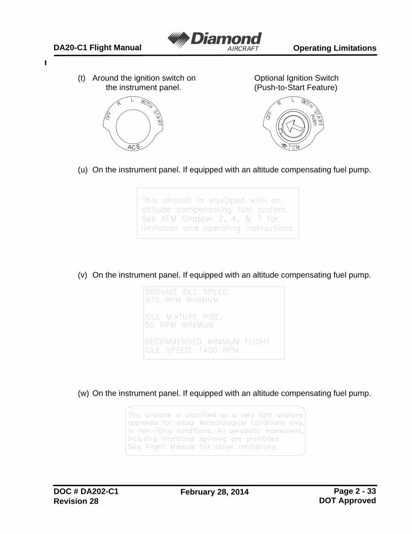
(t) Around the ignition switch on Optional Ignition Switchthe instrument panel. (Push-to-Start Feature)
(u) On the instrument panel. If equipped with an altitude compensating fuel pump.
(v) On the instrument panel. If equipped with an altitude compensating fuel pump.
(w) On the instrument panel. If equipped with an altitude compensating fuel pump.
ACS
Operating Limitations DA20-C1 Flight Manual
2.16 DEMONSTRATED CROSSWIND COMPONENT
The maximum demonstrated crosswind component is 20 kts. (37 km/h).
2.17 TEMPERATURE LIMITS
FOR AIRCRAFT WITH OTHER THAN WHITEUNDERSIDES. PARKING THE AIRCRAFT OVER A LIGHTCOLOURED OR REFLECTIVE SURFACE INCONDITIONS OF BRIGHT SUNLIGHT, PARTICULARLYAT HIGH OAT, IS NOT RECOMMENDED.
Temperature limit of the structure for the operation of the airplane:
Maximum T/O Temperature : 131°F (55°C) Structural Temperature
DOC # DA202-C1 May 15, 2012Revision 26 DOT Approved
1. GENERALThis supplement supplies the information necessary for the efficient operation of theDA20-C1 airplane when the Garmin G500, Integrated Display System, is installedas an optional system. The information contained within this supplement is to beused in conjunction with the complete manual.
This Supplement to the AFM is provided to acquaint the pilot with the limitations aswell as normal, abnormal and emergency operating procedures of the GarminG500. The limitations presented are pertinent to the operation of the G500 Systemas installed in the DA20-C1 airplane. Garmin provides a detailed Pilot’s Guide.Document Number 190-01102-02 (Current Revision). This reference material is notrequired to be on board the aircraft but does contain a more in depth description ofall the G500 functions.
This supplement is a permanent part of this Manual and must remain in this Manualas long as the Garmin G500 is installed.
The Garmin G500 Cockpit Reference Guide, Document Number 190-01102-03,(Current Revision) must be immediately available to the flight crew.
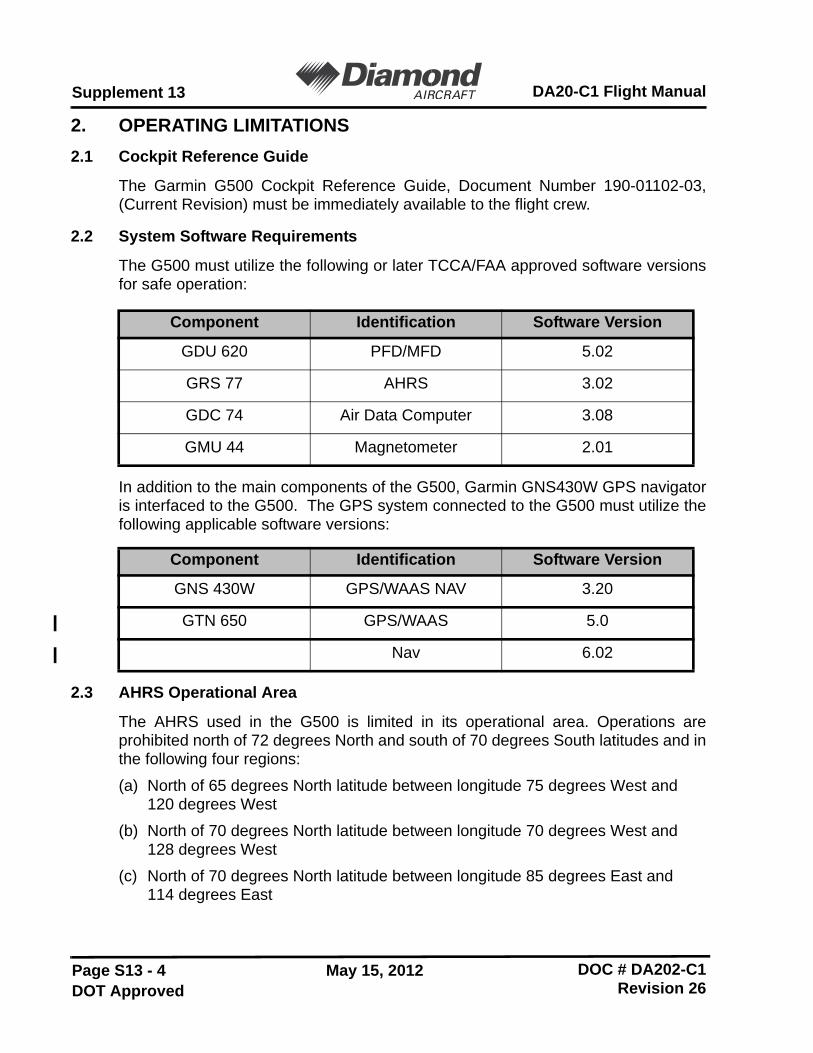
2.2 System Software Requirements
The G500 must utilize the following or later TCCA/FAA approved software versionsfor safe operation:
In addition to the main components of the G500, Garmin GNS430W GPS navigatoris interfaced to the G500. The GPS system connected to the G500 must utilize thefollowing applicable software versions:
2.3 AHRS Operational Area
The AHRS used in the G500 is limited in its operational area. Operations areprohibited north of 72 degrees North and south of 70 degrees South latitudes and inthe following four regions:
(a) North of 65 degrees North latitude between longitude 75 degrees West and 120 degrees West
(b) North of 70 degrees North latitude between longitude 70 degrees West and128 degrees West
(c) North of 70 degrees North latitude between longitude 85 degrees East and114 degrees East
Component Identification Software Version
GDU 620 PFD/MFD 5.02
GRS 77 AHRS 3.02
GDC 74 Air Data Computer 3.08
GMU 44 Magnetometer 2.01
Component Identification Software Version
GNS 430W GPS/WAAS NAV 3.20
GTN 650 GPS/WAAS 5.0
Nav 6.02
Page S13 - 9
Supplement 13DA20-C1 Flight Manual
DOC # DA202-C1 May 15, 2012Revision 26 DOT Approved
(h) Maneuvering speed on the left side of the instrument panel
(i) Trim placard on the upper left corner of the instrument panel
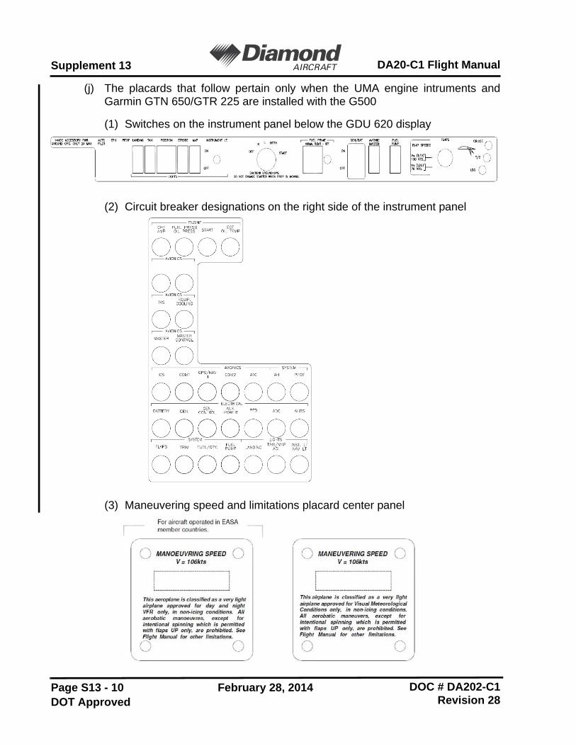
(j) The placards that follow pertain only when the UMA engine intruments andGarmin GTN 650/GTR 225 are installed with the G500
(1) Switches on the instrument panel below the GDU 620 display
(2) Circuit breaker designations on the right side of the instrument panel
(3) Maneuvering speed and limitations placard center panel
Page S13 - 11
Supplement 13DA20-C1 Flight Manual
DOC # DA202-C1 February 28, 2014Revision 28 DOT Approved
3. EMERGENCY PROCEDURES3.1 Emergency Procedures
There is no change in the emergency procedures.
3.2 Abnormal Procedures
These procedures supersede those presented as markings or placards, ordocumented in the aircraft’s TCCA/FAA approved AFM as a result of the installationof the G500 PFD/MFD system. All other emergency procedures remain in effect.
(a) If primary flight information (Heading, Altitude or Airspeed) on the PFD is notavailable or appears invalid, utilize the standby instruments installed aroundand adjacent to the G500, as required.
(b) The AHRS requires at least one GPS or air data input to function properly. Inthe unlikely event that GPS data or air data is not received by the AHRS, thesystem will subsequently lose attitude and heading and the pilot will be requiredto use the standby instrumentation. In this instance, the PFD will not provideAttitude, Heading, Altitude, or Airspeed information; however, if the PFD isreceiving valid GPS information, the reversionary data on the PFD providesGPS track and GPS Altitude data along with course information and deviationswhich are still valid and may be used to navigate.
(c) If navigation information on the PFD/MFD (HSI, RMI, WPT bearing anddistance information, or Moving Map Data) is not available or appears invalid,select an alternate source (via CDI key or 1-2 key) or utilize the data directlyfrom the navigation equipment as required.
(d) If any of the data sources from SVT become unreliable or unavailable, thedisplay of synthetic terrain will automatically revert to the non-SVT PFD displayof blue over brown. Additionally, if during the course of normal operations thereis any discrepancy between actual terrain around the aircraft and terrain shownon the SVT display, the display of synthetic vision should be manually turned offusing the procedure in paragraph 4.3 of this supplement.
(e) If GPS position information from the GNS430W is not valid due to an inability totrack GPS, the own-ship icon on the MFD is removed and “NO GPSPOSITION” text is overlaid on the MFD moving map. The system willannunciate a loss of integrity, “LOI” on the HSI. The LOI annunciation will becolored yellow and the HSI needle will flag. The pilot should select an alternatenavigation source (via CDI key or 1-2 key). Pressing the CDI soft key willchange the HSI navigation source. If GPS navigation is subsequently restored,the MFD moving map will display the own-ship icon, and the HIS navigationsource may be selected to GPS; at that time the LOI annunciation will beremoved.
A magnetometer failure is indicated by a HDG with a red X over it just to the left ofthe heading display. If the GDU620 is still receiving valid GPS ground track fromthe GNS navigator, the heading will be replaced with GPS ground track in magenta.The aircraft can be flown by reference to GPS ground track instead of heading. Inthis case, the autopilot will continue to fly in HDG mode, but the course being sentto the autopilot will be based on ground track instead of magnetic heading.
A complete Heading Failure (magnetometer and GPS ground track failure) isindicated by the digital heading presentation being replaced with a red X and thecompass rose digits being removed. The course pointer will indicate straight up andoperate much like a traditional CDI with the Omni-Bearing Selector being adjustedby the PFD knob set to CRS.
Under this condition, the pilot must use an alternate source of heading such as thestandby compass. If the installation includes an autopilot, the pilot workload may bereduced by operating that system in NAV mode.
3.3.2 AHRS Failure
A failure of the AHRS is indicated by a removal of the sky/ground presentation, ared X, and a yellow "AHRS FAILURE" shown on the PFD. A heading failure willalso occur as described above in 3.3.1.
(a) Set course datum using CRS selection of the PFD knob
(b) Seek VFR conditions or land as soon as practical.
3.3.3 Air Data Computer (ADC) Failure
Complete loss of the Air Data Computer is indicated by a red X and yellow text overthe airspeed, altimeter, vertical speed, TAS and OAT displays. Some derivedfunctions, such as true airspeed and wind calculations, will also be lost.
(a) Use Standby Airspeed Indicator and Altimeter
(b) Seek VFR conditions or land as soon as practical.
3.4 Loss of Electrical Power
In the event of a total loss of electrical power, the G500 system will cease to operateand the pilot must utilize the standby instruments to fly the aircraft.
Page S13 - 13
Supplement 13DA20-C1 Flight Manual
DOC # DA202-C1 February 28, 2014Revision 28 DOT Approved
3.5 WARNINGS, CAUTIONS and Advisories
The following tables show the color and significance of the Warning, Caution, andAdvisory messages which can appear on the G500 displays.
The G500 cockpit reference guide and the G500 pilot's guide contain detaileddescriptions of the annunciator system and all Warnings, Cautions and Advisories.
NOTE
WARNING annunciations - RedAnnunciation Pilot Action Cause
AIRSPEED FAIL Use Standby Airspeed
Display system is not receiving airspeed input from the air data computer; accompanied by a red X through the airspeed display.
ALTITUDE FAIL Use Standby Altitude.
Display system is not receiving altitude input from the air data computer; accompanied by a red X through the altimeter display.
VERT SPD FAIL Cross check instruments.
Display system is not receiving vertical speed input from the air data computer; accompanied by a red X through the vertical speed display.
HDG
Use standby Magnetic Compass or GPS track information.
Display system is not receiving valid heading input from the AHRS; accompanied by a red X through the digital heading display.
Red XReference the data source or alternate equipment.
A red X through any display field, indicates that display field is not receiving data or is corrupted.
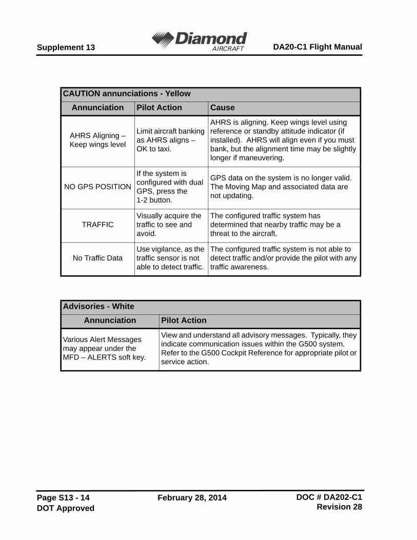
CAUTION annunciations - YellowAnnunciation Pilot Action Cause
AHRS Aligning –Keep wings level
Limit aircraft banking as AHRS aligns – OK to taxi.
AHRS is aligning. Keep wings level using reference or standby attitude indicator (if installed). AHRS will align even if you must bank, but the alignment time may be slightly longer if maneuvering.
NO GPS POSITION
If the system is configured with dual GPS, press the 1-2 button.
GPS data on the system is no longer valid. The Moving Map and associated data are not updating.
TRAFFICVisually acquire the traffic to see and avoid.
The configured traffic system has determined that nearby traffic may be a threat to the aircraft.
No Traffic DataUse vigilance, as the traffic sensor is not able to detect traffic.
The configured traffic system is not able to detect traffic and/or provide the pilot with any traffic awareness.
Advisories - WhiteAnnunciation Pilot Action
Various Alert Messages may appear under the MFD – ALERTS soft key.
View and understand all advisory messages. Typically, they indicate communication issues within the G500 system. Refer to the G500 Cockpit Reference for appropriate pilot or service action.
Page S13 - 15
Supplement 13DA20-C1 Flight Manual
DOC # DA202-C1 February 28, 2014Revision 28 DOT Approved
4. NORMAL PROCEDURESDetailed operating procedures are described in the Garmin G500 CockpitReference Guide, Document No. 190-01102-03, Rev D or a later appropriaterevision and in the Garmin G500 Pilot’s Guide, Document No. 190-01102-02, RevC, or a later appropriate revision.
4.1 Database Cards
DO NOT OPERATE THE GARMIN G500 SYSTEMUSING AN OUT-OF-DATE DATABASE. OUT-OF-DATE DATABASE INFORMATION CAN CAUSE AFLIGHT SAFETY HAZARD.
The G500 utilizes several databases. Database titlesdisplay in yellow if expired or in question. The G500receives the calendar data from the GPS, but only afteracquiring a position fix. Database cycle information isdisplayed at power up on the MFD display, but moredetailed information is available on the AUX pages.Internal database prevents incorrect data beingdisplayed.
The upper Secure Digital (SD) data card slot is typically vacant as it is used forsoftware maintenance and navigational database updates. The lower data card slotshould contain a data card with the system’s terrain/obstacle information andoptional data including Safe Taxi, FliteCharts and ChartView electronic charts.
The terrain databases are updated periodically and have no expiration date.Coverage of the terrain database is between North 75º latitude and South 60ºlatitude in all longitudes. Coverage of the airport terrain database is worldwide.
The obstacle database contains data for obstacles, such as towers, that pose apotential hazard to aircraft. Obstacles, 200 feet and higher, are included in theobstacle database. It is very important to note that not all obstacles are necessarilycharted and therefore may not be contained in the obstacle database. Coverage ofthe obstacle database includes the United States and Europe. This database isupdated on a 56-day cycle.
The Garmin SafeTaxi database contains detailed airport diagrams for selectedairports. These diagrams aid in following ground control instructions by accuratelydisplaying the aircraft position on the map in relation to taxiways, ramps, runways,terminals, and services. This database is updated on a 56-day cycle.
The Garmin FliteCharts database contains procedure charts for the coverage areapurchased. This database is updated on a 28-day cycle. If not updated within 180days of the expiration date, FliteCharts will no longer function.
The Jeppesen ChartView electronic charts database contains procedure charts forthe coverage area purchased. An own-ship position icon will be displayed on thesecharts. This database is updated on a 14-day cycle. If not updated within 70 days ofthe expiration date, ChartView will no longer function.
Page S13 - 17
Supplement 13DA20-C1 Flight Manual
DOC # DA202-C1 February 28, 2014Revision 28 DOT Approved
4.2 PFD Knob and Soft Keys
The basic PFD controls are on the left side of the GDU 620 unit, next to andbeneath the PFD display. The rotary knob performs the function annunciated on thedisplay just to the upper left of the HSI: HDG, CRS, ALT, V/S, or BARO. If nofunction is annunciated then the knob is providing a HDG function. Assigning thefunction of the knob is done by pressing/releasing one of the dedicated functionbuttons to the left of the display.
After 10 seconds of inactivity in another mode, the PFDknob selected mode will revert to HEADING mode.
- Press the desired PFD mode selection key (HDG, CRS, ALT, V/S, or BARO). A window will be displayed near the upper right corner of the HSI showing the current value for that mode.
- Turn the PFD knob to select the desired value.
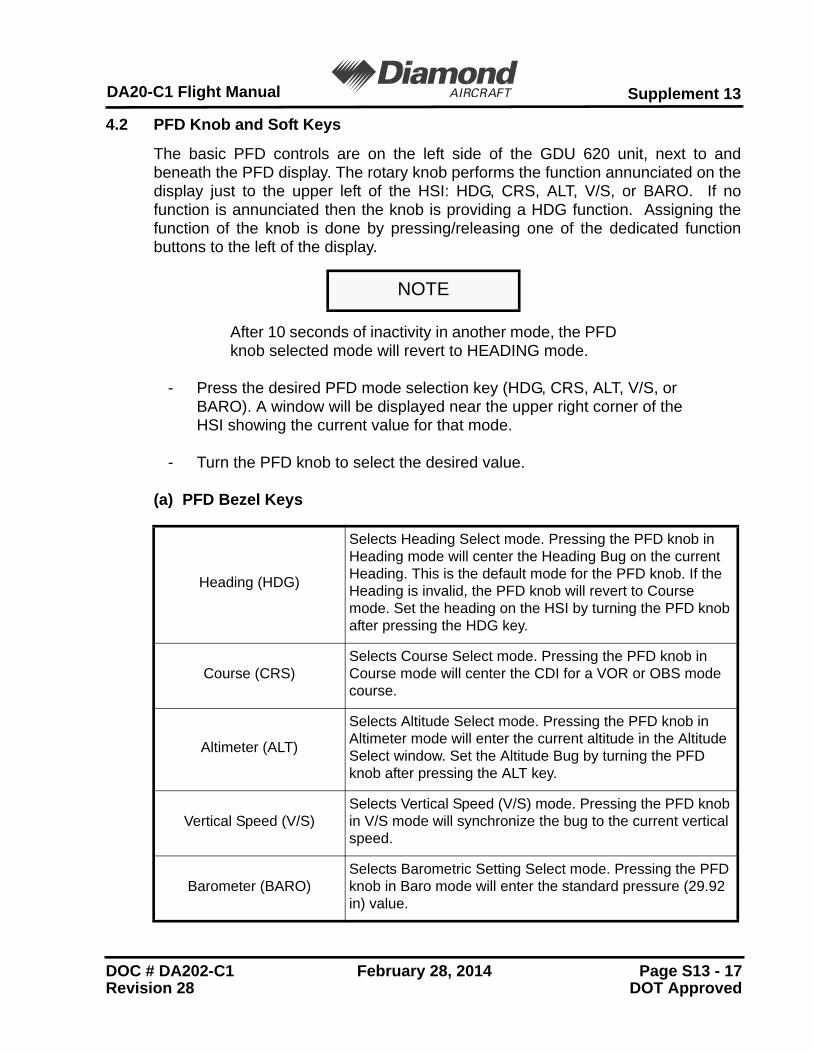
(a) PFD Bezel Keys
NOTE
Heading (HDG)
Selects Heading Select mode. Pressing the PFD knob in Heading mode will center the Heading Bug on the current Heading. This is the default mode for the PFD knob. If the Heading is invalid, the PFD knob will revert to Course mode. Set the heading on the HSI by turning the PFD knob after pressing the HDG key.
Course (CRS)Selects Course Select mode. Pressing the PFD knob in Course mode will center the CDI for a VOR or OBS mode course.
Altimeter (ALT)
Selects Altitude Select mode. Pressing the PFD knob in Altimeter mode will enter the current altitude in the Altitude Select window. Set the Altitude Bug by turning the PFD knob after pressing the ALT key.
Vertical Speed (V/S)Selects Vertical Speed (V/S) mode. Pressing the PFD knob in V/S mode will synchronize the bug to the current vertical speed.
Barometer (BARO)Selects Barometric Setting Select mode. Pressing the PFD knob in Baro mode will enter the standard pressure (29.92 in) value.
The soft keys are located along the bottoms of the displays below the soft keylabels. The soft key labels shown depend on the soft key level or page beingdisplayed. The soft keys can be used to select the appropriate soft key function.
When a soft key is selected, its color changes to black text on gray background andremains this way until it is turned off, at which time it reverts to white text on blackbackground. When a soft key function is disabled, the soft key label is subdued(dimmed). Soft keys revert to the previous level after 45 seconds of inactivity.
4.3 MFD Knobs and MFD Soft KeysThe MFD controls are on the right side of the GDU 620 unit, next to and beneath theMFD display. The rotary knobs scroll through various page groups and pages of theMFD and manipulate data and settings by pressing the knob to activate a cursor.
Soft keys at the bottom of the display allow for some quick functions to beperformed on each page. The soft keys operate by press and release. Moredetailed configuration is typically available by pressing the MENU button, which ison the right side of the display.
Pressing and holding down the CLR key is a good way to get back to the main mappage on the MFD. This can be used as a quick way back, or when the pilot hasselected a submenu within the system.
CDI The CDI soft key toggles between the selection of GPS or VOR/LOC as the active navigation source.
PFD Pressing the PFD soft key displays the BRG and BACK soft keys.
BRG The BRG soft key cycles through the available bearing indicator modes (NAV, GPS, ADF, or None).
SYN VISThe SYN VIS soft key is available if Synthetic Vision Technology™ is installed. It enables Synthetic Vision and displays the associated soft keys.
SYN TERR The SYN TERR soft key is available if Synthetic Vision Technology™ is installed and enables synthetic terrain depiction.
HRZN HDGThe HRZN HDG soft key is available if Synthetic Vision Technology™ is installed. Pressing this key enables horizon heading marks and digits.
APTSIGNS The APTSIGNS soft key is available if Synthetic Vision Technology™ is installed and enables airport sign posts.
BACK The BACK soft key returns to the pages default soft key options.
Page S13 - 19
Supplement 13DA20-C1 Flight Manual
DOC # DA202-C1 February 28, 2014Revision 28 DOT Approved
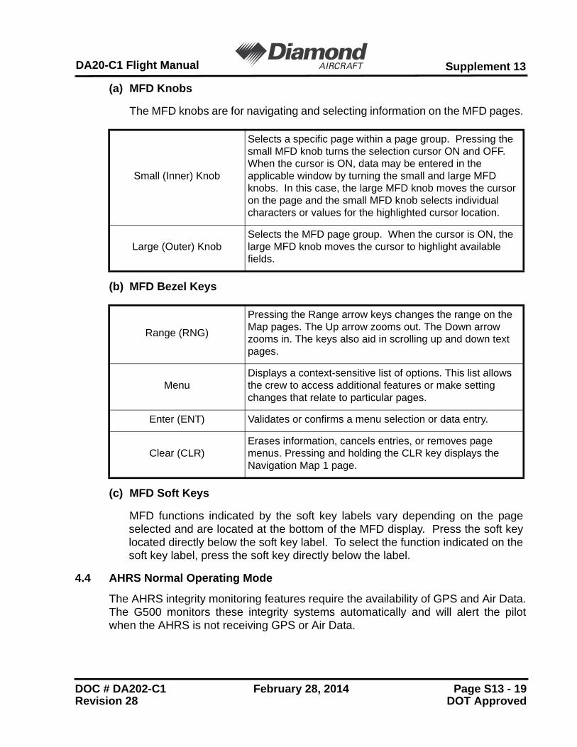
(a) MFD Knobs
The MFD knobs are for navigating and selecting information on the MFD pages.
(b) MFD Bezel Keys
(c) MFD Soft Keys
MFD functions indicated by the soft key labels vary depending on the pageselected and are located at the bottom of the MFD display. Press the soft keylocated directly below the soft key label. To select the function indicated on thesoft key label, press the soft key directly below the label.
4.4 AHRS Normal Operating Mode
The AHRS integrity monitoring features require the availability of GPS and Air Data.The G500 monitors these integrity systems automatically and will alert the pilotwhen the AHRS is not receiving GPS or Air Data.
Small (Inner) Knob
Selects a specific page within a page group. Pressing the small MFD knob turns the selection cursor ON and OFF. When the cursor is ON, data may be entered in the applicable window by turning the small and large MFD knobs. In this case, the large MFD knob moves the cursor on the page and the small MFD knob selects individual characters or values for the highlighted cursor location.
Large (Outer) KnobSelects the MFD page group. When the cursor is ON, the large MFD knob moves the cursor to highlight available fields.
Range (RNG)
Pressing the Range arrow keys changes the range on the Map pages. The Up arrow zooms out. The Down arrow zooms in. The keys also aid in scrolling up and down text pages.
MenuDisplays a context-sensitive list of options. This list allows the crew to access additional features or make setting changes that relate to particular pages.
Enter (ENT) Validates or confirms a menu selection or data entry.
Clear (CLR)Erases information, cancels entries, or removes page menus. Pressing and holding the CLR key displays the Navigation Map 1 page.
The G500 HSI will auto slew, i.e. automatically rotate the GPS course pointer to thedesired course defined by each GPS leg. The system will also auto slew theVHFNAV course pointer when the CDl transitions to a LOC setting if an ILS, LOC,LOC BC, LDA, or SDF approach is activated in the GPS/WAAS navigator.
The VHFNAV (green) course pointer will only auto slew if the approach is active inthe navigator, the LOC frequency is loaded in the active NAV frequency, and thenthe HSI source is changed to the corresponding VHFNAV for the approach. BackCourse approaches will auto slew to the reciprocal course.
The system is not capable of automatically setting the inbound VHFNAV coursepointer if an approach is not active in the GNS Navigation System.
4.6 Terrain Display
The G500 terrain and obstacle information appears on the MFD display as red andyellow tiles or towers, and is depicted for advisory only. Aircraft maneuvers andnavigation must not be predicated upon the use of the terrain display. Terrain unitalerts are advisory only and are not equivalent to warnings provided by TAWS.
4.7 Synthetic Vision Technology (SVT)
The SVT system may be turned on or off, as desired. To access the synthetic visionsystem soft key menu, press the PFD soft key on the GDU 620, followed by theSYN VIS soft key. Synthetic vision terrain, horizon headings, and airport signs canbe toggled on and off from this menu. Press the BACK soft key to return to the rootPFD menu.
4.8 Autopilot Operations
The G500 PFD/MFD System offers various integration capabilities dependentmainly upon the type of autopilot installed in a particular aircraft.
5. PERFORMANCEThere is no change in the performance of the airplane.
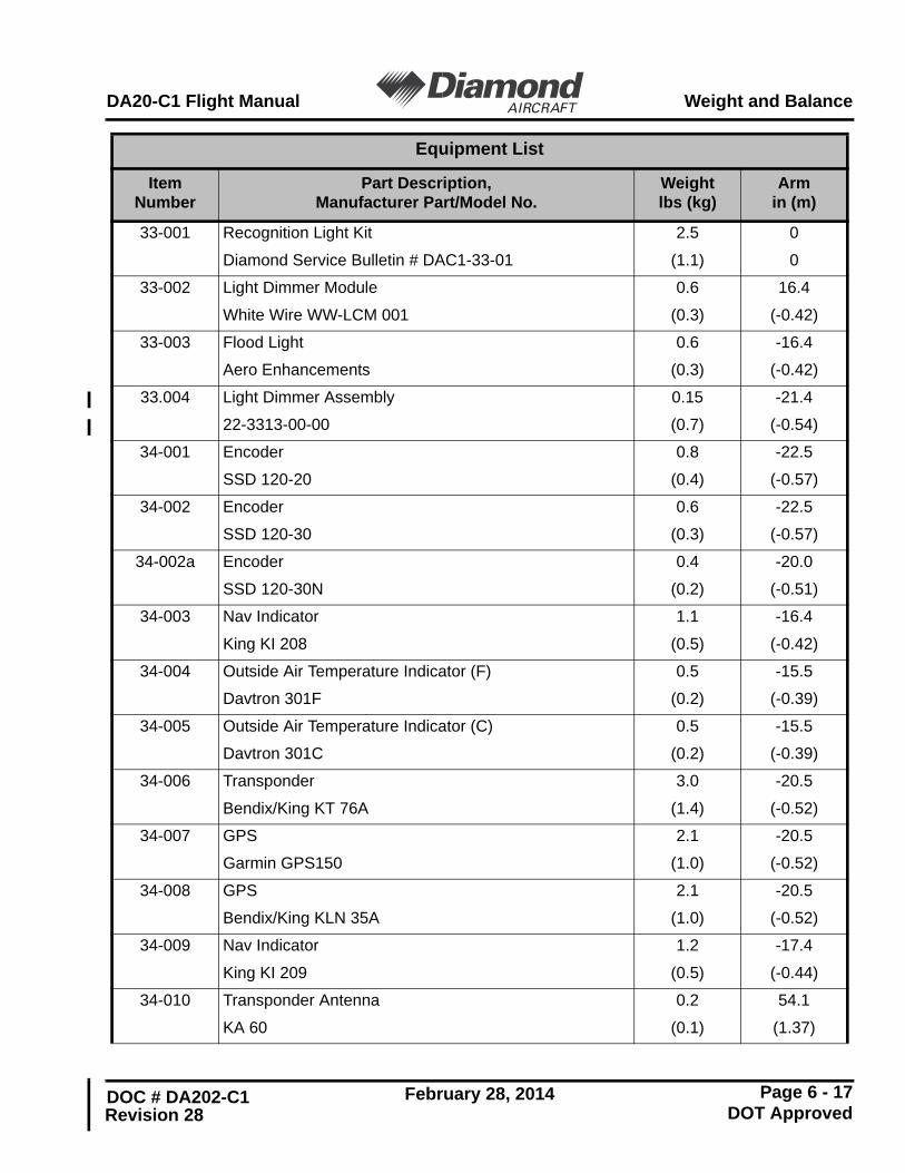
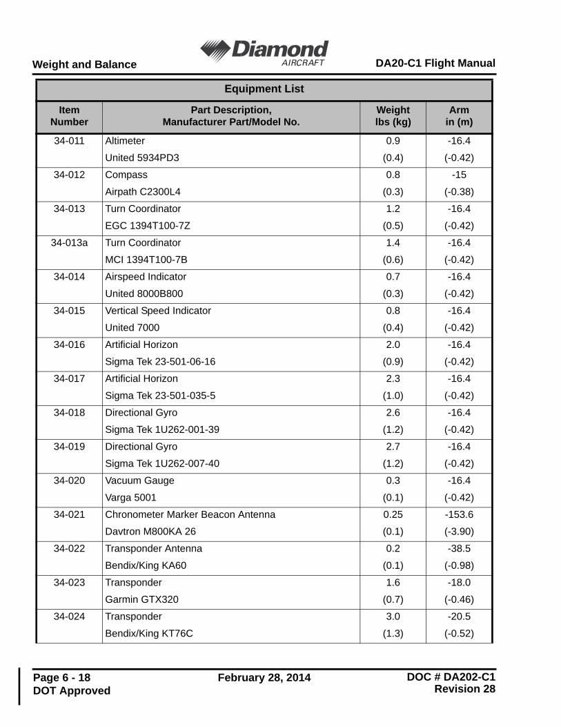
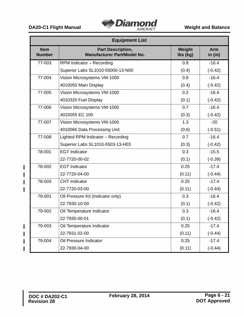
6. WEIGHT AND BALANCE / EQUIPMENT LISTUpon removal and installation of the Garmin G500, the change of empty mass andcorresponding center of gravity of the airplane must be recorded according toChapter 6 of the AFM.
Page S13 - 21
Supplement 13DA20-C1 Flight Manual
DOC # DA202-C1 February 28, 2014Revision 28 DOT Approved
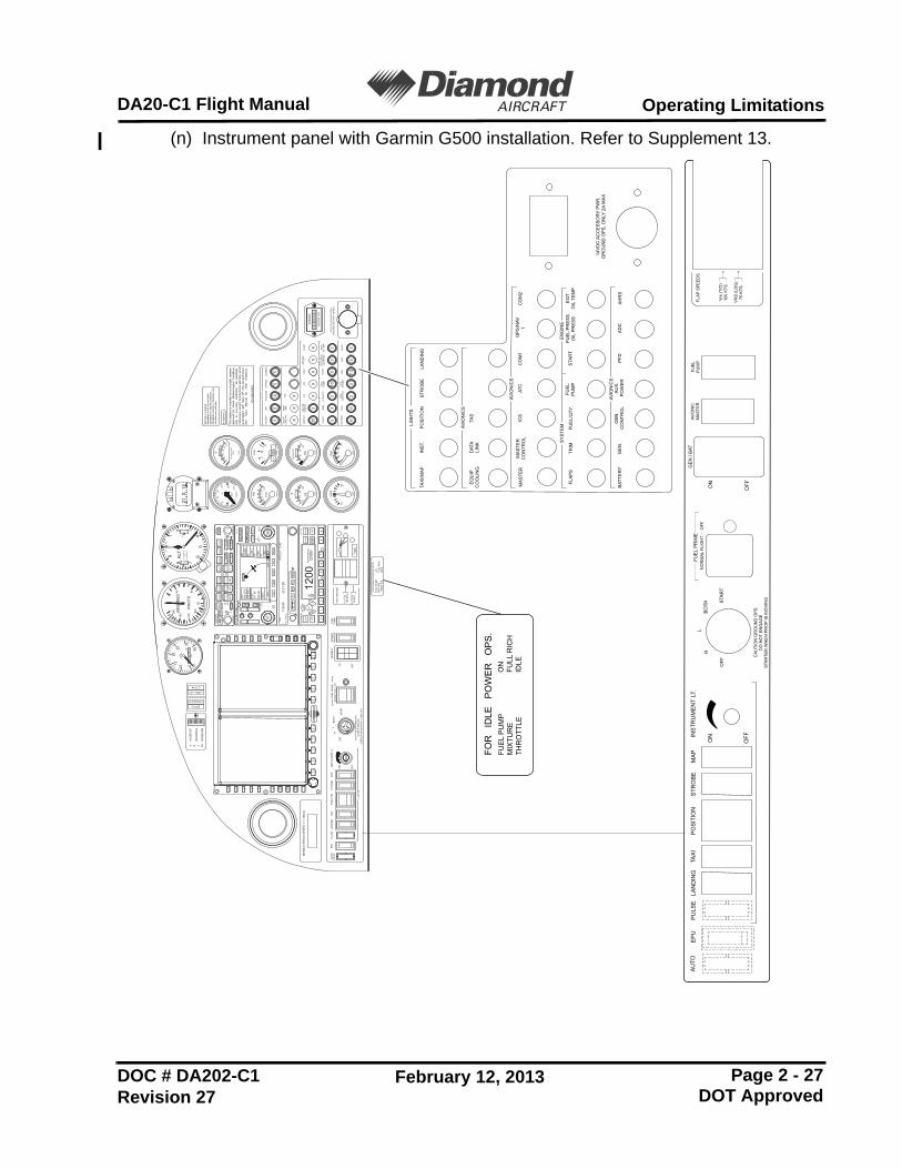
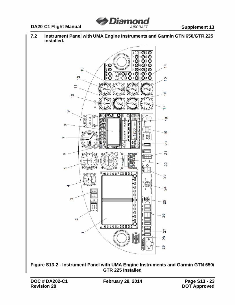
7. DESCRIPTION OF THE AIRPLANE AND ITS SYSTEMS7.1 Instrument Panel
Figure S13-1 - Instrument Panel with Garmin G500 System Installed
DOC # DA202-C1 February 28, 2014Revision 28 DOT Approved
7.2 Avionics - General
The G500 system consists of:
- Garmin Display Unit (GDU) 620 (PFD/MFD)
- Garmin data Computer (GDC) 74A [Air Data Computer (ADC)]
- Garmin Reference System (GRS) 77 [Attitude and Heading Reference System (AHRS)]
- Garmin Magnetometer Unit (GMU) 44
- Garmin Navigation System GNS 400 Series Radio’s or GTN 600 Series Radio’s
- Garmin Temperature Probe (GTP) 59.
The system presents primary flight instrumentation and navigation. It also providesa moving map to the pilot through large format displays.
(a) GDU 620 Display
This displays the real time True Airspeed calculations and selectable winds aloftdata, as well as airplane ground speed, GPS active waypoint, distance-to-waypoint, desired/actual track, and more.
In normal operating mode, the Primary Flight Display (PFD) presents graphicalflight instrumentation (attitude, heading, airspeed, vertical speed). The Multi-Function Flight Display (MFD) normally displays a full color movingmap with navigation and flight plan information, traffic, weather and terrain.
(b) GRS 77 AHRS
The GRS 77 is an attitude and heading reference unit that provides aircraftattitude and flight characteristics information to the GDU 620. The unit containsadvanced tilt sensors, accelerometers, and rate sensors. In addition, theGRS 77 interfaces with both the GDC 74A air data computer and the GMU 44magnetometer. The GRS 77 also utilizes GPS signals sent from the GPS/WAAS navigator. Actual attitude and heading information is sent usingARINC 429 digital interface to the GDU 620.
The GDC 74A air data computer receives information from the pitot/staticsystem and the GTP 59 outside air temperature (OAT) sensor. The GDC 74A isresponsible for providing pressure altitude, airspeed, vertical speed, and OATinformation to the G500 system. The GDC 74A provides data to the GDU 620and GRS 77 using ARINC 429 digital interfaces. The GDC 74A alsocommunicates maintenance and configuration information to the GDU 620using an RS-232 interface.
(d) GMU 44 Magnetometer
The GMU 44 magnetometer senses magnetic field information. Data is sent tothe GRS 77 AHRS for processing to determine aircraft magnetic heading. Thisunit receives power directly from the GRS 77 and communicates with theGRS 77 using an RS-485 digital interface.
(e) GNS 430W GPS (Optional)
The GNS 430W unit is a panel-mount GPS navigator with a color moving map.Position and flight plan data are displayed on the GDU 620 MFD via RS-232and ARINC 429 interfaces. GPS position information is also forwarded to theGRS 77 AHRS in order to ensure normal AHRS operation. The GNS 430Walso provides LOC/GS information for display on the GDU 620 HSI via anARINC 429 interface.
(f) GTN 650 GPS (Optional)
The GTN 650 unit is a touch screen, panel-mount, GPS navigator with a colourmoving map. Position and flight plan data are displayed on the GDU 620 MFDvia RS-232 and ARINC 429 interfaces. GPS position information is alsoforwarded to the GRS 77 AHRS in order to ensure normal AHRS operation.The GTN 650 also provides LOC/GS information for display on the GDU 620HSI via an ARINC 429 interface.
Page S13 - 27
Supplement 13DA20-C1 Flight Manual
DOC # DA202-C1 February 28, 2014Revision 28 DOT Approved
Figure S13-3 - G500 System Overview with Optional and Required Equipment