38
AIRTRONIC D2-D4 / HYDRONIC D5SC BASIC REPAIR ANALYSIS A WORLD OF COMFORT
AIRTRONIC D2-D4 / HYDRONIC D5SC
BASIC REPAIR ANALYSIS
A W O R L D O F C O M F O R T
This document is not intended to be all-inclusive
Table of Contents
2
REVISION LEVEL A - 12/01/13
Chapter Content Page
Identifying Different Repair Modes . . . . . . . . . . . . . . . . . . . . . . . . . . . . . . . . . . . . . . . . . . . . . . . . . . . . . . . . . . . . . . . . . . . . . . . . . . . . . . . . . . 3
Before Beginning Repairs . . . . . . . . . . . . . . . . . . . . . . . . . . . . . . . . . . . . . . . . . . . . . . . . . . . . . . . . . . . . . . . . . . . . . . . . . . . . . . . . . . . . . . . . . . 4
Heaters as Part of Other Systems . . . . . . . . . . . . . . . . . . . . . . . . . . . . . . . . . . . . . . . . . . . . . . . . . . . . . . . . . . . . . . . . . . . . . . . . . . . . . . . . . . . . 6
Combustion Blower Motor . . . . . . . . . . . . . . . . . . . . . . . . . . . . . . . . . . . . . . . . . . . . . . . . . . . . . . . . . . . . . . . . . . . . . . . . . . . . . . . . . . . . . . . . . 7
FMP - Fuel Metering Pump . . . . . . . . . . . . . . . . . . . . . . . . . . . . . . . . . . . . . . . . . . . . . . . . . . . . . . . . . . . . . . . . . . . . . . . . . . . . . . . . . . . . . . . . 12
Burner Tube / FlameChamber . . . . . . . . . . . . . . . . . . . . . . . . . . . . . . . . . . . . . . . . . . . . . . . . . . . . . . . . . . . . . . . . . . . . . . . . . . . . . . . . . . . . . . 15
Glow Pin . . . . . . . . . . . . . . . . . . . . . . . . . . . . . . . . . . . . . . . . . . . . . . . . . . . . . . . . . . . . . . . . . . . . . . . . . . . . . . . . . . . . . . . . . . . . . . . . . . . 21
ECU – Control Unit . . . . . . . . . . . . . . . . . . . . . . . . . . . . . . . . . . . . . . . . . . . . . . . . . . . . . . . . . . . . . . . . . . . . . . . . . . . . . . . . . . . . . . . . . . . . . . 23
Combo Sensor — Overheating / Flame Sensor . . . . . . . . . . . . . . . . . . . . . . . . . . . . . . . . . . . . . . . . . . . . . . . . . . . . . . . . . . . . . . . . . . . . . . . . . 26
Coolant Pump . . . . . . . . . . . . . . . . . . . . . . . . . . . . . . . . . . . . . . . . . . . . . . . . . . . . . . . . . . . . . . . . . . . . . . . . . . . . . . . . . . . . . . . . . . . . . . . . . . 28
Heater Controllers . . . . . . . . . . . . . . . . . . . . . . . . . . . . . . . . . . . . . . . . . . . . . . . . . . . . . . . . . . . . . . . . . . . . . . . . . . . . . . . . . . . . . . . . . . . . . . . 31
Entire Heater . . . . . . . . . . . . . . . . . . . . . . . . . . . . . . . . . . . . . . . . . . . . . . . . . . . . . . . . . . . . . . . . . . . . . . . . . . . . . . . . . . . . . . . . . . . . . . . . . . . 34
Repair — Don’t Replace . . . . . . . . . . . . . . . . . . . . . . . . . . . . . . . . . . . . . . . . . . . . . . . . . . . . . . . . . . . . . . . . . . . . . . . . . . . . . . . . . . . . . . . . . . 36
Non-Genuine Parts . . . . . . . . . . . . . . . . . . . . . . . . . . . . . . . . . . . . . . . . . . . . . . . . . . . . . . . . . . . . . . . . . . . . . . . . . . . . . . . . . . . . . . . . . . . . . . 37
Warrantywillautomaticallypay30minutestodiagnoseand30minutestotest-plusrepairflatratesfromthewarrantylabortimeguide.Using this manual you should be well on the way to a resolution and repair within 30 mnutes . Warranty will not pay for unnecessary extended repair times . Please use this manual as a supplement to the diagnostic and repair manuals to help reduce unapplied labor times for diagnostics and repair to help reduce your unapplied labor times . .
CAUTION: Indicates that personal injury or damage to equipment may occur unless specific guidelines are followed. DANGER: Indicates that serious or fatal injury may result if specific guidelines are not followed.
This document aims to support service technicians and end users in North America. This does not replace documentation produced by J. Eberspächer.
The installation instructions and standards described in this document are NOT APPLICABLE TO MARINE INSTALLATIONS.Please consult a certified Espar Marine dealer for marine installation.
This publication was correct at the time of going to print. However, Espar Inc. has a policy of continuous improvement and reserves the right to amend any specifications without prior notice.
10
11
12
13
4
5
1
2
3
6
7
8
9
PLEASE NOTE!
14

This document is not intended to be all-inclusive
The purpose of this document is to help better identify the root cause of many common service issues and accurately distinguish between warranty - non-warranty and maintenance-related issues.
IDENTIFYING DIFFERENT REPAIR MODESA warrantable repair is:A failure due to defects in material or workmanship during the products base warranty coverage period.
A non-warrantable repair would fall into one of these categories: • Damage due to an improper installation • Damage from the environment in which it operates • Lack of maintenance • Use of poor quality fuel or excessive fuel additive • Damage incurred during removal, reinstallation or repair • Damage from a previous repair visit • Use of non-genuine service parts
AIRTRONIC D2
HYDRONIC D5
3
1 Identifying Different Repair ModesREVISION LEVEL A - 12/01/13
This document is not intended to be all-inclusive
2 Before Beginning Repairs
4
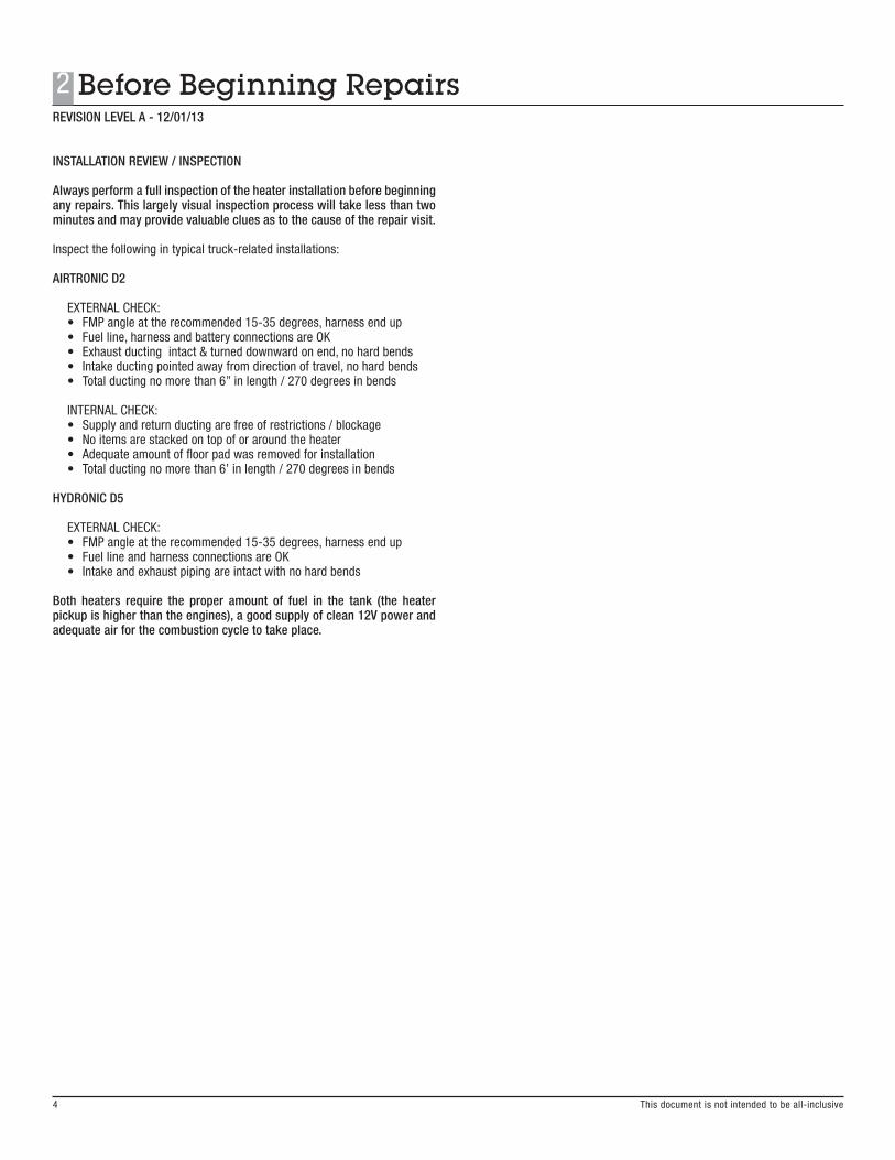
INSTALLATION REVIEW / INSPECTION
Always perform a full inspection of the heater installation before beginning any repairs . This largely visual inspection process will take less than two minutes and may provide valuable clues as to the cause of the repair visit .
Inspect the following in typical truck-related installations:
AIRTRONIC D2
EXTERNAL CHECK: • FMP angle at the recommended 15-35 degrees, harness end up• Fuel line, harness and battery connections are OK• Exhaust ducting intact & turned downward on end, no hard bends• Intake ducting pointed away from direction of travel, no hard bends• Total ducting no more than 6” in length / 270 degrees in bends
INTERNAL CHECK: • Supply and return ducting are free of restrictions / blockage• No items are stacked on top of or around the heater • Adequate amount of floor pad was removed for installation• Total ducting no more than 6’ in length / 270 degrees in bends
HYDRONIC D5
EXTERNAL CHECK: • FMP angle at the recommended 15-35 degrees, harness end up• Fuel line and harness connections are OK• Intake and exhaust piping are intact with no hard bends
Both heaters require the proper amount of fuel in the tank (the heater pickup is higher than the engines), a good supply of clean 12V power and adequate air for the combustion cycle to take place .
REVISION LEVEL A - 12/01/13
This document is not intended to be all-inclusive
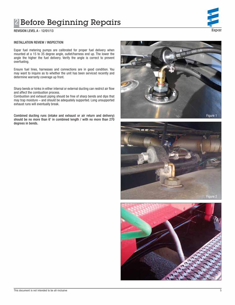
INSTALLATION REVIEW / INSPECTION
Espar fuel metering pumps are calibrated for proper fuel delivery when mounted at a 15 to 35 degree angle, outlet/harness end up. The lower the angle the higher the fuel delivery. Verify the angle is correct to prevent overfueling.
Ensure fuel lines, harnesses and connections are in good condition. You may want to inquire as to whether the unit has been serviced recently and determine warranty coverage up front.
Sharp bends or kinks in either internal or external ducting can restrict air flow and affect the combustion process.Combustion and exhaust piping should be free of sharp bends and dips that may trap moisture – and should be adequately supported. Long unsupported exhaust runs will eventually break.
Combined ducting runs (intake and exhaust or air return and delivery) should be no more than 6’ in combined length / with no more than 270 degrees in bends .
Figure 1
Figure 2
Figure 3
5
2REVISION LEVEL A - 12/01/13
Before Beginning Repairs
3 Heater as part of other Systems
6
REVISION LEVEL A - 12/01/13
This document is not intended to be all-inclusive
HEATERS AS PART OF OTHER SYSTEMS
Be aware that heaters installed as part of original equipment or aftermarket idle reduction systems may be subject to installation or operational factors outside of Espar’s responsibility.
Factors to consider:Certain OE installed or aftermarket APU / Idle Reduction systems are designed to govern heater operation instead of using our traditional controllers, introducing a new diagnostic considerationOE installed products may be subject to governing by the units LVD system. Cutoff voltages may vary as available power supplies changeWhen part of battery packages be sure system voltages are taken into consideration
Some of the popular idle-reduction systems using Espar heaters are the: Bergstrom NITE System, ClimaCab, Freightliner ParkSmart, International MaxxPower, Thermo King Tri-Pac to name a few.
All types of heater installations, including those mentioned above, are subject to the pre-repair installation review recommendation – which could directly affect how you bill repair parts and labor charges .

This document is not intended to be all-inclusive
REVISION LEVEL A - 12/01/13
7
4 Combustion Blower Motor
BASICS OF REPAIR ANALYSIS
The most common causes of non-warranty Blower Motor instances are:
AIRTRONIC D2
Figure 4
AIRTRONIC – Damage to wheel from housing compression onto the wheel, unnecessary disassembly.
HYDRONIC D5
Figure 5
HYDRONIC – Ingestion of road debris.

This document is not intended to be all-inclusive
4 Combustion Blower Motor
8
REVISION LEVEL A - 12/01/13
BASICS OF REPAIR ANALYSIS
AIRTRONIC D2/D4 BLOWERWith heavy friction marks, typically caused by crushing / top-stacking of the blower motor housing or overtightening of the intake ducting clamp. This puts pressure directly on the wheel and will ultimately burn up the blower motor.
Repair Classification: Abuse, improper installation
Figure 6
Figure 7

9
4 Combustion Blower MotorREVISION LEVEL A - 12/01/13
This document is not intended to be all-inclusive
IMPELLER DAMAGE
Impeller Damage - Can occur from abrupt interruption of the power supply (and the resulting flame blowback onto the plastic wheel) or impacts during repair.
Wheels are balanced and should never be removed as part of the repair process. Wheels cannot be broken during normal operation with a proper installation.
Repair Classification: Improper operation or disassembly
Figure 8 Figure 9
4 Combustion Blower Motor
10
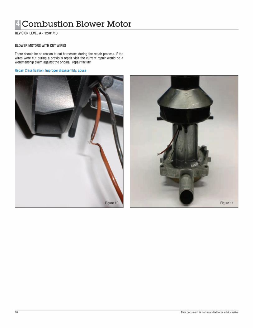
BLOWER MOTORS WITH CUT WIRES
There should be no reason to cut harnesses during the repair process. If the wires were cut during a previous repair visit the current repair would be a workmanship claim against the original repair facility.
Repair Classification: Improper disassembly, abuse
Figure 10 Figure 11
REVISION LEVEL A - 12/01/13
This document is not intended to be all-inclusive
This document is not intended to be all-inclusive
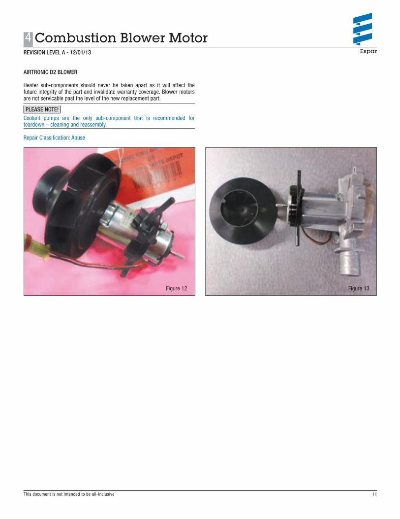
AIRTRONIC D2 BLOWER
Heater sub-components should never be taken apart as it will affect the future integrity of the part and invalidate warranty coverage. Blower motors are not servicable past the level of the new replacement part.
Coolant pumps are the only sub-component that is recommended for teardown – cleaning and reassembly.
Repair Classification: Abuse
Figure 12 Figure 13
11
4 Combustion Blower MotorREVISION LEVEL A - 12/01/13
PLEASE NOTE!
This document is not intended to be all-inclusive
5 FMP - Fuel Metering Pump
12
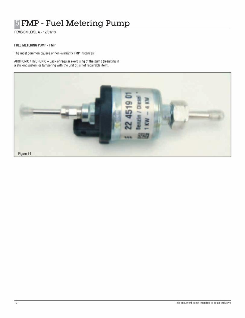
FUEL METERING PUMP - FMP
The most common causes of non-warranty FMP instances:
AIRTRONIC / HYDRONIC – Lack of regular exercising of the pump (resulting in a sticking piston) or tampering with the unit (it is not repairable item).
Figure 14
REVISION LEVEL A - 12/01/13
This document is not intended to be all-inclusive
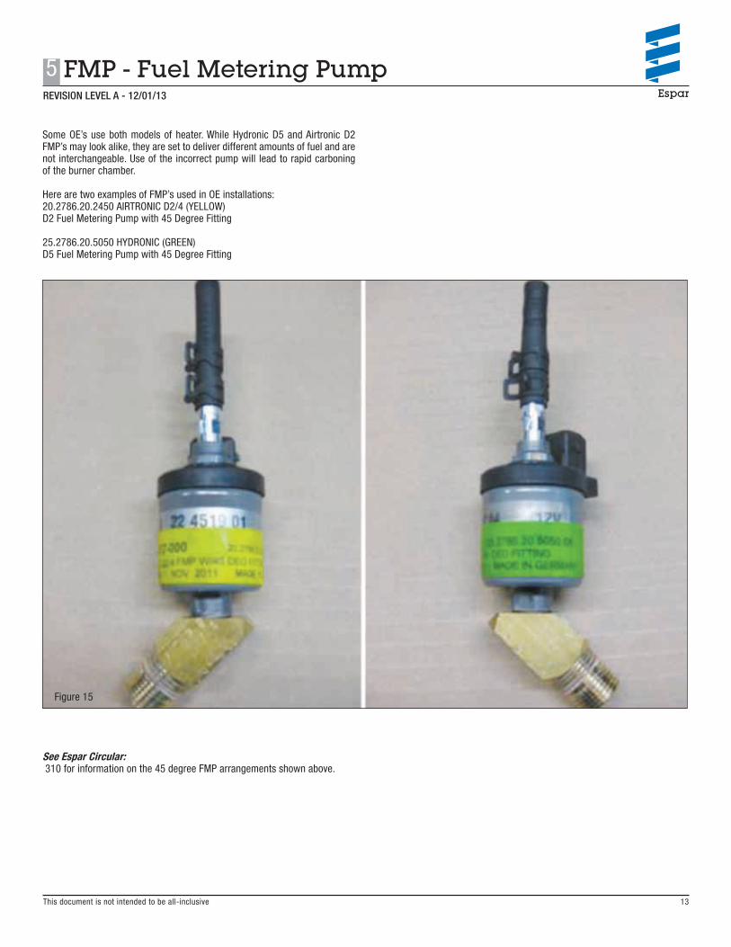
Some OE’s use both models of heater. While Hydronic D5 and Airtronic D2 FMP’s may look alike, they are set to deliver different amounts of fuel and are not interchangeable. Use of the incorrect pump will lead to rapid carboning of the burner chamber.
Here are two examples of FMP’s used in OE installations:20.2786.20.2450 AIRTRONIC D2/4 (YELLOW)D2 Fuel Metering Pump with 45 Degree Fitting
25.2786.20.5050 HYDRONIC (GREEN)D5 Fuel Metering Pump with 45 Degree Fitting
Figure 15
See Espar Circular: 310 for information on the 45 degree FMP arrangements shown above.
13
5 FMP - Fuel Metering Pump REVISION LEVEL A - 12/01/13
5 FMP - Fuel Metering Pump
14
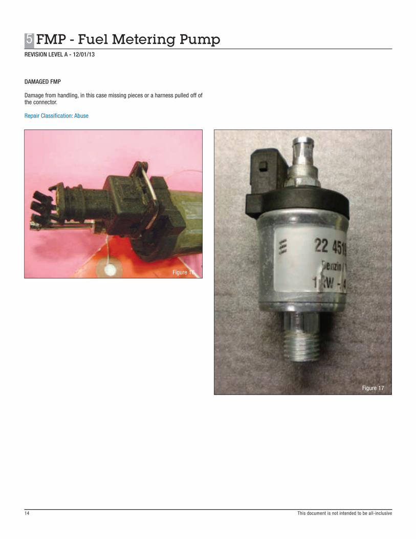
DAMAGED FMP
Damage from handling, in this case missing pieces or a harness pulled off of the connector.
Repair Classification: Abuse
Figure 16
Figure 17
REVISION LEVEL A - 12/01/13
This document is not intended to be all-inclusive

6 Burner Tube / Flame Chamber
15
REVISION LEVEL A - 12/01/13
This document is not intended to be all-inclusive
BURNER TUBE / FLAME CHAMBER
The most common causes of non-warranty blower motor failures are:
AIRTRONIC – Lack of or improper PM servicing, improper fuel pump angle / over-fueling, restricted combustion intake / exhaust airflow.
HYDRONIC – Lack of or improper PM servicing, improper fuel pump angle /over-fueling, restricted combustion intake / exhaust airflow.
Figure 18

This document is not intended to be all-inclusive
AIRTRONIC D2
Check to see if the vent hole on the side of glow pin is plugged with carbon. Cleaning this area is part of normal maintenance as a plugged hole will affect proper heater ignition and operation. Be sure the atomizing screen is fully seated in the chamber and not blocking the vent hole and that the exhaust pipe is tuned downward at the end to reduce exhaust restriction.
Repair Classification: Maintenance
Figure 19 Figure 20
6 Burner Tube / Flame ChamberREVISION LEVEL A - 12/01/13
16

6 Burner Tube / Flame Chamber
17
REVISION LEVEL A - 12/01/13
This document is not intended to be all-inclusive
AIRTRONIC D2
Ensure the atomizing screen is fully seated in the chamber. If not it can block the vent hole and lead to rapid carboning of the heater. If you have a unit that is heavily carboned and this is found it was most likely installed incorrectly during the last PM service.Always use the supplied screen insertion tool (shown < here) to properly seat the replacement screen.
Repair Classification: Maintenance
Figure 21
See Espar Bulletins:TB281 for Airtronic pre-season maintenance guidelinesTB280 for Hydronic pre-season maintenance guidelines
Figure 22
REVISION LEVEL A - 12/01/13
This document is not intended to be all-inclusive 18
6 Burner Tube / Flame Chamber
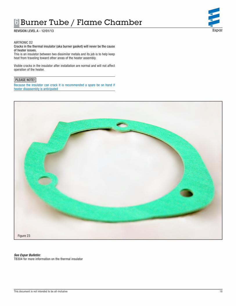
AIRTRONIC D2Cracks in the thermal insulator (aka burner gasket) will never be the cause of heater issues . This is an insulator between two dissimilar metals and its job is to help keep heat from traveling toward other areas of the heater assembly.
Visible cracks in the insulator after installation are normal and will not affect operation of the heater.
Because the insulator can crack it is recommended a spare be on hand if heater disassembly is anticipated
Figure 23
See Espar Bulletin:TB304 for more information on the thermal insulator
PLEASE NOTE!

This document is not intended to be all-inclusive
AIRTRONIC D2
If the burner is cover with carbon it is most likely from incomplete combustion or over-fueling. Check the FMP angle and combustion intake/exhaust ducting. If the unit has not been serviced - check the atomizing screen and vent hole.
Look for carboning as a common symptom with a code 52
Repair Classification: Installation or maintenance related
Figure 24
See Espar Bulletin: TB282 for Airtronic carbon cleaning guidelines
Figure 25
REVISION LEVEL A - 12/01/13
6 Burner Tube / Flame Chamber
19

REVISION LEVEL A - 12/01/13
20
6 Burner Tube / Flame Chamber
This document is not intended to be all-inclusive
AIRTRONIC D2
Check to see if the burner tube has white or crystalline build-up. This will typically be the result of over-use of fuel additives or excessive use of biodiesel blends.
Repair Classification: Maintenance
Figure 26

REVISION LEVEL A - 12/01/13
7 Glow Pin
21 This document is not intended to be all-inclusive
GLOW PIN
The most common causes of non-warranty glow pin failures are:
Rough handling during the removal process, use of unregulated 12V power during testing, pulling the harness wire off during removal by gripping the boot and wire together when removing the boot.
Figure 27
This document is not intended to be all-inclusive
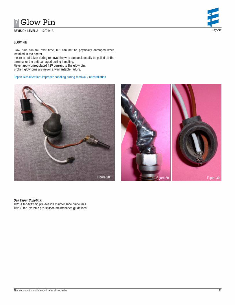
GLOW PIN
Glow pins can fail over time, but can not be physically damaged while installed in the heater. If care is not taken during removal the wire can accidentally be pulled off the terminal or the unit damaged during handling.Never apply unregulated 12V current to the glow pin . Broken glow pins are never a warrantable failure .
Repair Classification: Improper handling during removal / reinstallation
Figure 28
See Espar Bulletins:TB281 for Airtronic pre-season maintenance guidelinesTB280 for Hydronic pre-season maintenance guidelines
Figure 29 Figure 30
REVISION LEVEL A - 12/01/13
22
7 Glow Pin
REVISION LEVEL A - 12/01/13
8 ECU — Control Unit
23 This document is not intended to be all-inclusive
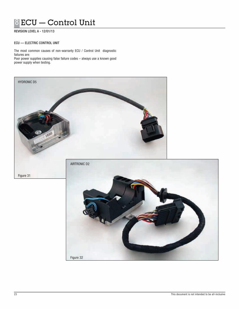
ECU — ELECTRIC CONTROL UNIT
The most common causes of non-warranty ECU / Control Unit diagnostic failures are: Poor power supplies causing false failure codes – always use a known good power supply when testing.
HYDRONIC D5
AIRTRONIC D2
Figure 31
Figure 32
REVISION LEVEL A - 12/01/13
24
8 ECU — Control Unit
This document is not intended to be all-inclusive
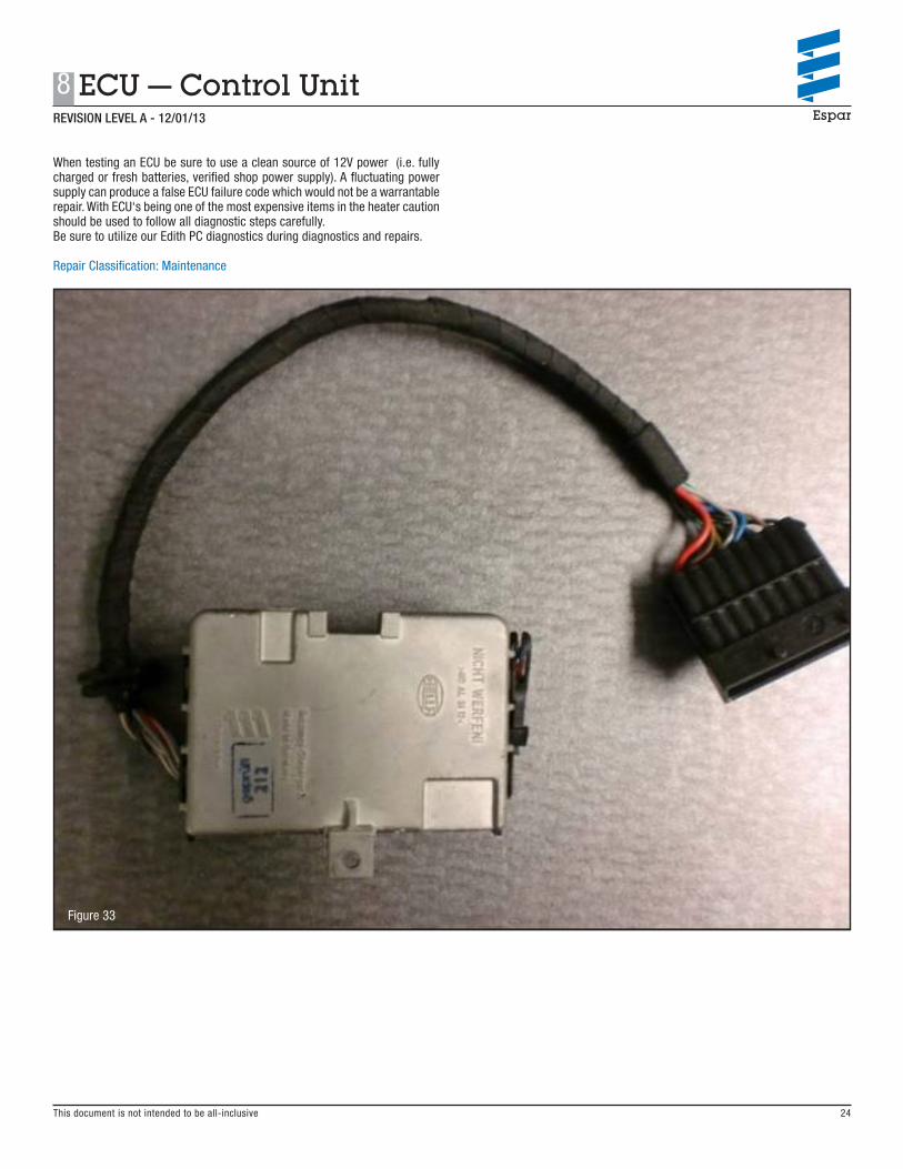
When testing an ECU be sure to use a clean source of 12V power (i.e. fully charged or fresh batteries, verified shop power supply). A fluctuating power supply can produce a false ECU failure code which would not be a warrantable repair. With ECU‘s being one of the most expensive items in the heater caution should be used to follow all diagnostic steps carefully. Be sure to utilize our Edith PC diagnostics during diagnostics and repairs.
Repair Classification: Maintenance
Figure 33
This document is not intended to be all-inclusive
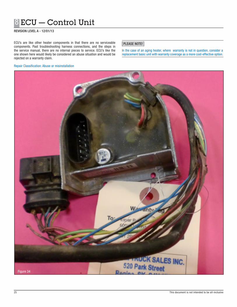
ECU’s are like other heater components in that there are no serviceable components. Past troubleshooting harness connections, and the steps in the service manual, there are no internal pieces to service. ECU’s like the one shown here would likely be considered an abuse situation and would be rejected on a warranty claim.
Repair Classification: Abuse or misinstallation
Figure 34
In the case of an aging heater, where warranty is not in question, consider a replacement basic unit with warranty coverage as a more cost-effective option.
REVISION LEVEL A - 12/01/13
8 ECU — Control Unit
25
PLEASE NOTE!
REVISION LEVEL A - 12/01/13
26
9 Combo Sensor — Overheating / Flame Sensor
This document is not intended to be all-inclusive
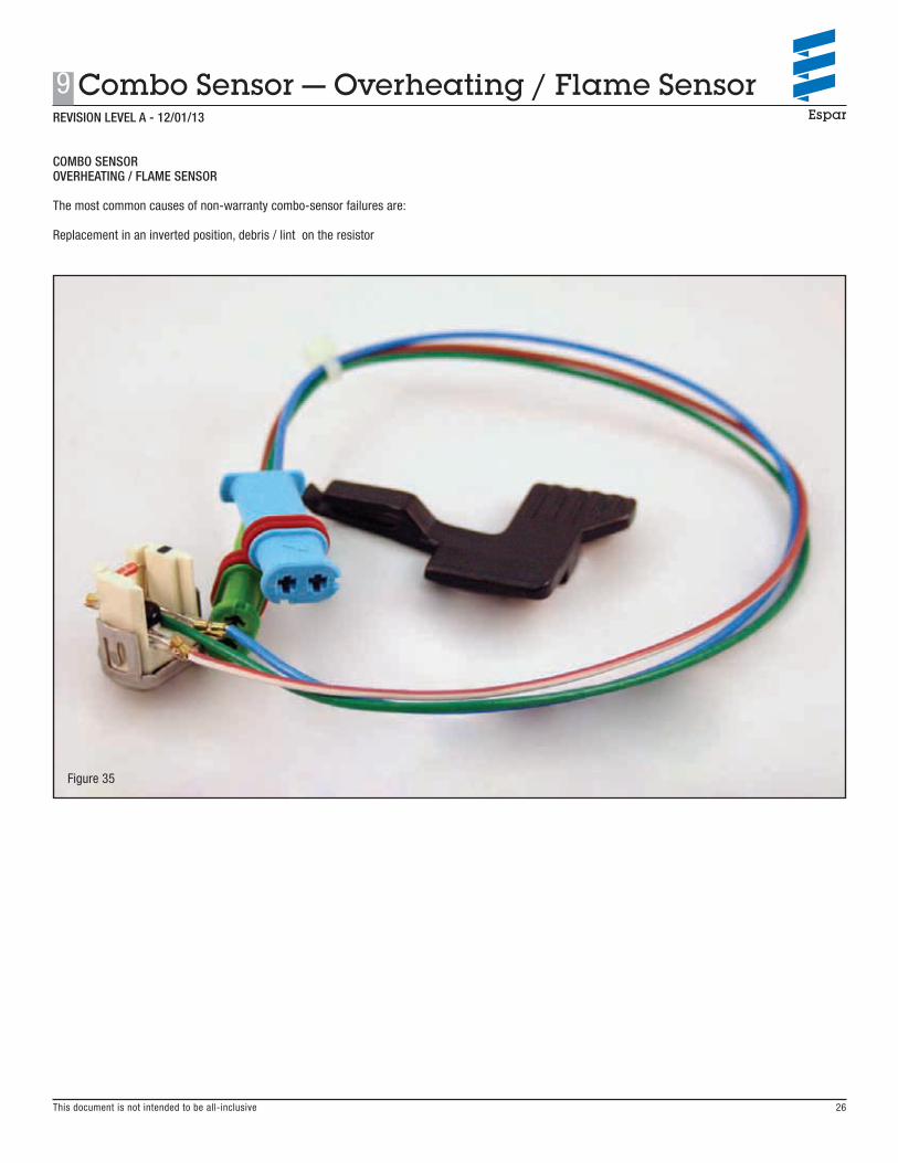
COMBO SENSOROVERHEATING / FLAME SENSOR
The most common causes of non-warranty combo-sensor failures are:
Replacement in an inverted position, debris / lint on the resistor
Figure 35

REVISION LEVEL A - 12/01/13
9 Combo Sensor — Overheating / Flame Sensor
27 This document is not intended to be all-inclusive
Before replacing the combo sensor ensure the unit is not installed upside down (from a previous repair or maintenance) or that pet hair / lint is not covering the resistor located on top.
Repair Classification: Maintenance
Figure 36
If the harness is cut or damaged due to improper reinstallation -
Repair Classification: Maintenance
Figure 37

This document is not intended to be all-inclusive
REVISION LEVEL A - 12/01/13
28
10 Coolant Pump
HYDRONIC D5 COOLANT PUMP
The most common causes of non-warranty coolant pump failures are:
System contamination restricting operation and damage to the inlet/outlet pipes.
Figure 38

This document is not intended to be all-inclusive
10 Coolant Pump
29
REVISION LEVEL A - 12/01/13
HYDRONIC D5 COOLANT PUMP
Visually inspect the coolant pump for damage. Road debris impacting the pump or unsupported coolant lines can cause damage to the pump inlet/outlet pipes. Care must also be taken during removal of the pump. Damage as noted above is not covered under warranty.
Repair Classification: Maintenance / road hazard / R&R
Figure 39
Figure 40

REVISION LEVEL A - 12/01/13
30
10 Coolant Pump
This document is not intended to be all-inclusive
HYDRONIC D5 COOLANT PUMP
Disassamble the pump and visually inspect it for internal contamination. Inconsistent coolant care can contribute to contamination and debris that can collect in the coolant pump housing and affect operation. The pump can be cleaned and seals replaced – see TB302.
Repair Classification: Maintenance
Figure 41
See Espar Bulletin:TB302 for Hydronic coolant pump cleaning
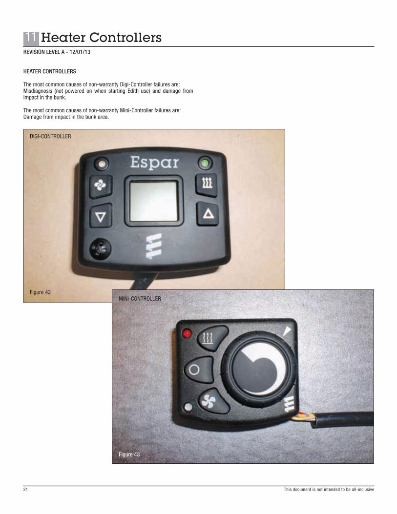
HEATER CONTROLLERS
The most common causes of non-warranty Digi-Controller failures are:Misdiagnosis (not powered on when starting Edith use) and damage from impact in the bunk.
The most common causes of non-warranty Mini-Controller failures are:Damage from impact in the bunk area.
DIGI-CONTROLLER
Figure 42 MINI-CONTROLLER
Figure 43
REVISION LEVEL A - 12/01/13
11 Heater Controllers
31 This document is not intended to be all-inclusive

This document is not intended to be all-inclusive
Visually inspect the controller for damage from impacts or abuse. Typically controllers are mounted in a secure location and external damage would be a non-warrantable failure.
Repair Classification: Abuse or improper installation
Figure 44
Figure 45
32
11 Heater ControllersREVISION LEVEL A - 12/01/13

REVISION LEVEL A - 12/01/13
11 Heater Controllers
33 This document is not intended to be all-inclusive
If you encounter a controller harness that has been damaged due to interaction with mounting screws it would be considerd a non-warranty failure. There may, however, be some recourse thru the OE manufacturer or dealer who performed the original installation.
Repair Classification: Improper installation
Figure 46

REVISION LEVEL A - 12/01/13
34
12 Entire Heater
This document is not intended to be all-inclusive
ENTIRE HEATER
Heater assemblies do not fail, components do. You will sometimes however encounter the “heater-in-a-box“ scenario. After diagnosis you must decide whether a repair or a replacment is the best path to pursue.
Figure 47

REVISION LEVEL A - 12/01/13
This document is not intended to be all-inclusive
12 Entire Heater
35
If an entire heater is brought in for repair it should be noted that while repairs can be performed the actual cause of the failure may not be attainable and as such warranty may not apply.
Figure 48
When removing an entire heater for service most variables that may have caused the need for repair are effectively removed from the diagnostic process.
• Fuel supply and delivery• Combustion intake / exhaust routing• Wiring harness and power cables• General installation verification• In / under cab environmental conditions
In cases like this the repair can still be performed but the root casue of the problem may not be determmined, leaving open the possibility of repeat problem occurances .
This document is not intended to be all-inclusive
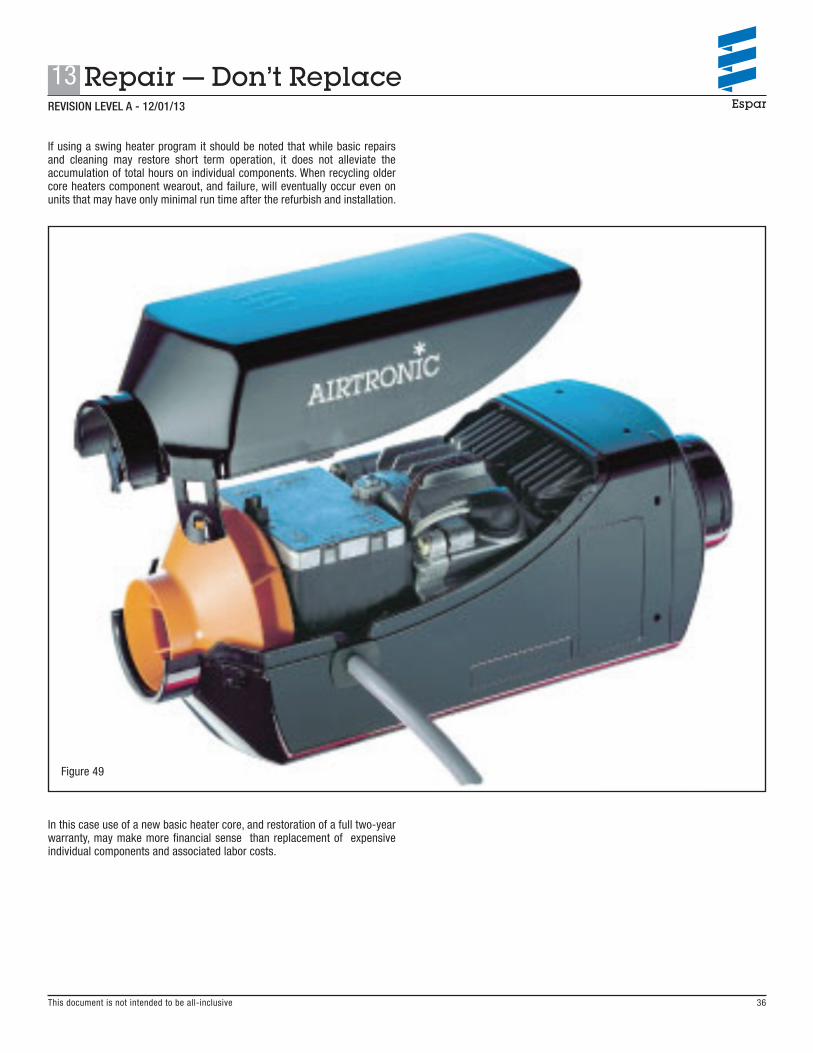
If using a swing heater program it should be noted that while basic repairs and cleaning may restore short term operation, it does not alleviate the accumulation of total hours on individual components. When recycling older core heaters component wearout, and failure, will eventually occur even on units that may have only minimal run time after the refurbish and installation.
Figure 49
In this case use of a new basic heater core, and restoration of a full two-year warranty, may make more financial sense than replacement of expensive individual components and associated labor costs.
36
13 Repair — Don’t ReplaceREVISION LEVEL A - 12/01/13

14 Non-Genuine Parts
37
Espar has a strict policy against the use of non-genuine parts in it’s heaters. This also applies to use of non-genuine parts in warranty repairs. Warranty claims cannot be submitted on non-genuine parts, either as the primary failure or as related to a progressive damage situation.
A listing of current known non-genuine parts will be maintained here for your protection.
Current known Non-Genuine Parts:GLOW-PIN-AIRTRONIC D2Manufacturer: Thermo KingIdentification: TK logo on rubber boot Black-and-white harness (genuine is brown-and-white)
Because this part may cause progressive damage to other components, claims submitted for glow pin failures will require return of the failed part to verify it was a genuine Espar component.
REVISION LEVEL A - 12/01/13
This document is not intended to be all-inclusive
www.espar.com
Espar Products, Inc.
(800) 387-4800
(905) 670-0960
www.espar.com AIRT
RON
IC D
2/D
4 —
HYD
RON
IC D
5SC
BASI
C RE
PAIR
MAN
UAL
Ve
rsio
n 12
/201
3 Su
bjec
t to
cha
nge
with
out
notic
e.


