AIRTRONIC D2/D4 Installation, Troubleshooting & Parts Manual Espar P/N: 610-103-0901 November 2001 AIRTRONIC For Heater Models Release period AIRTRONIC D2 - 12 volt 25 2069 05 00 00 November 2001 AIRTRONIC D2 - 24 volt 25 2070 05 00 00 November 2001 AIRTRONIC D4 - 12 volt 25 2113 05 00 00 November 2001 AIRTRONIC D4 - 24 volt 25 2114 05 00 00 November 2001
Transcript
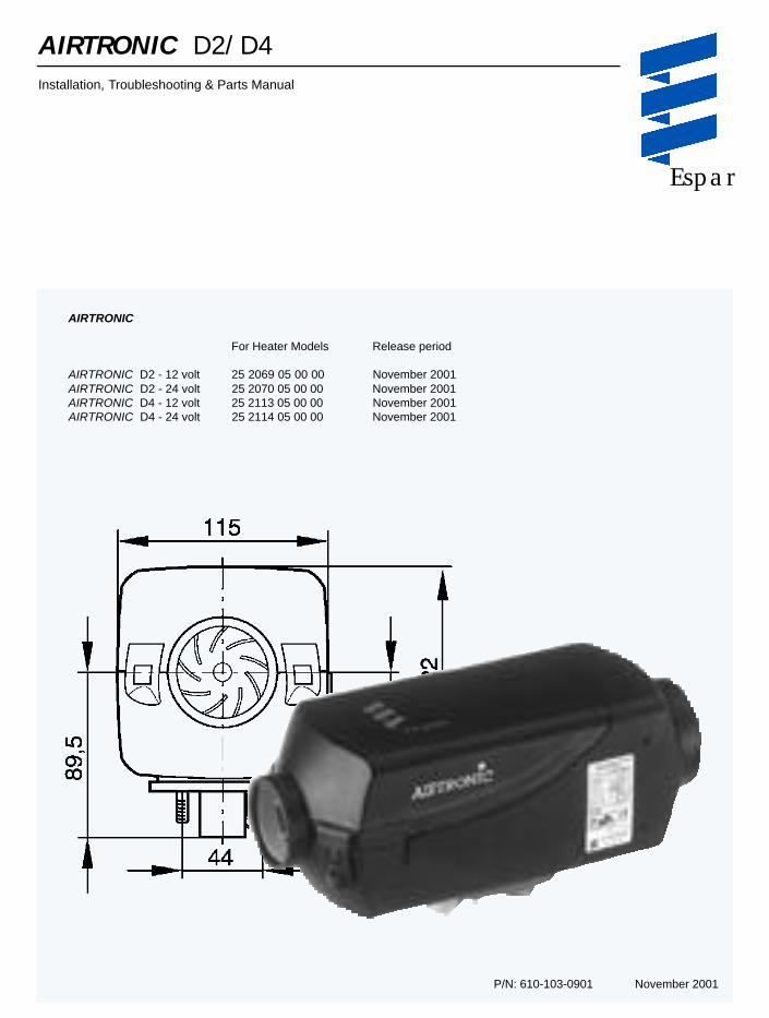
AIRTRONIC D2/D4Installation, Troubleshooting & Parts Manual
Espar
P/N: 610-103-0901 November 2001
AIRTRONIC
For Heater Models Release period
AIRTRONIC D2 - 12 volt 25 2069 05 00 00 November 2001AIRTRONIC D2 - 24 volt 25 2070 05 00 00 November 2001AIRTRONIC D4 - 12 volt 25 2113 05 00 00 November 2001AIRTRONIC D4 - 24 volt 25 2114 05 00 00 November 2001
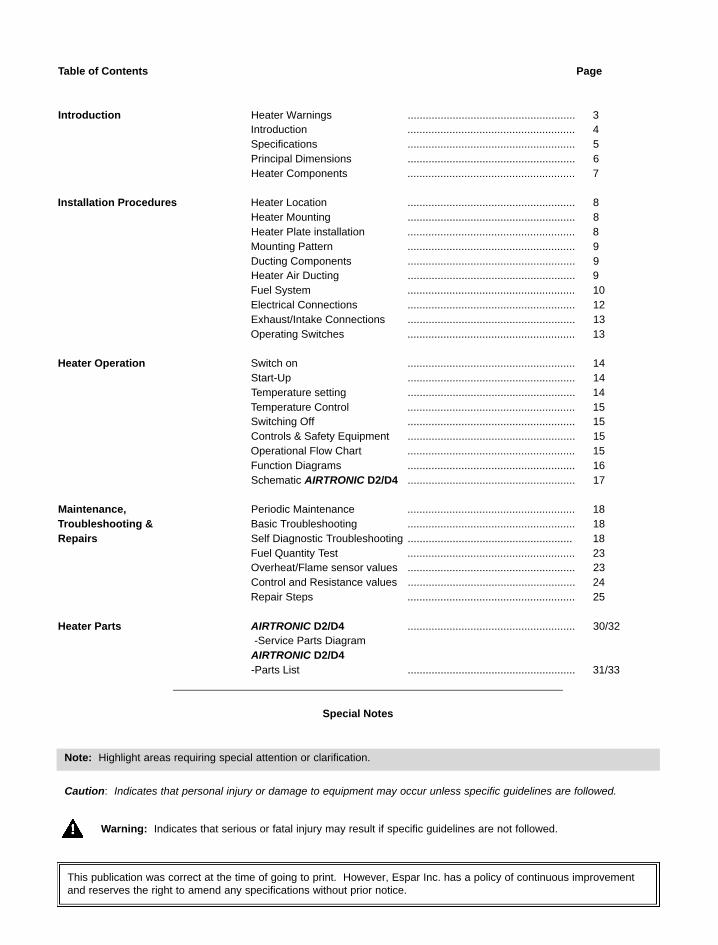
This publication was correct at the time of going to print. However, Espar Inc. has a policy of continuous improvementand reserves the right to amend any specifications without prior notice.
Fuel Quantity Test ........................................................ 23Overheat/Flame sensor values ........................................................ 23Control and Resistance values ........................................................ 24Repair Steps ........................................................ 25
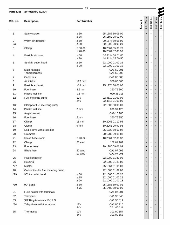
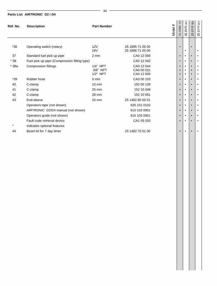
Heater Parts AIRTRONIC D2/D4 ........................................................ 30/32-Service Parts Diagram
AIRTRONIC D2/D4-Parts List ........................................................ 31/33
Special Notes
Note: Highlight areas requiring special attention or clarification.
Caution: Indicates that personal injury or damage to equipment may occur unless specific guidelines are followed.
Warning: Indicates that serious or fatal injury may result if specific guidelines are not followed.
3
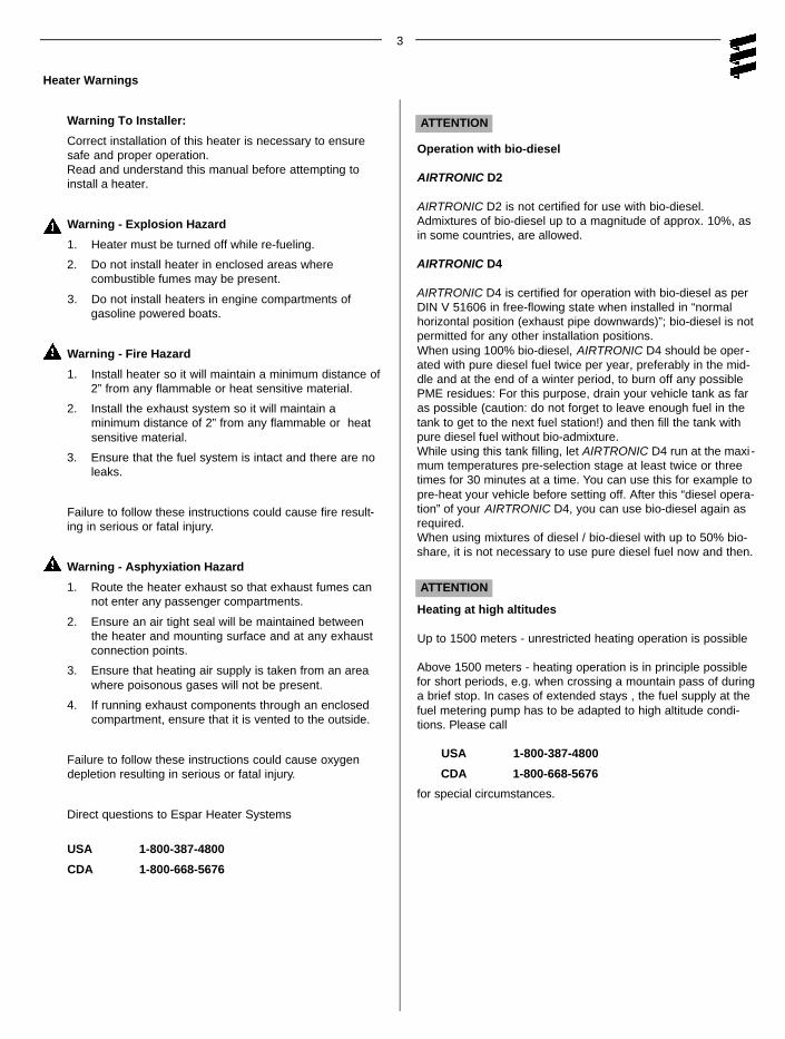
Heater Warnings
Warning To Installer:
Correct installation of this heater is necessary to ensuresafe and proper operation. Read and understand this manual before attempting toinstall a heater.
Warning - Explosion Hazard
1. Heater must be turned off while re-fueling.
2. Do not install heater in enclosed areas wherecombustible fumes may be present.
3. Do not install heaters in engine compartments of gasoline powered boats.
Warning - Fire Hazard
1. Install heater so it will maintain a minimum distance of2” from any flammable or heat sensitive material.
2. Install the exhaust system so it will maintain aminimum distance of 2” from any flammable or heat sensitive material.
3. Ensure that the fuel system is intact and there are no leaks.
Failure to follow these instructions could cause fire result-ing in serious or fatal injury.
Warning - Asphyxiation Hazard
1. Route the heater exhaust so that exhaust fumes cannot enter any passenger compartments.
2. Ensure an air tight seal will be maintained between the heater and mounting surface and at any exhaust connection points.
3. Ensure that heating air supply is taken from an area where poisonous gases will not be present.
4. If running exhaust components through an enclosed compartment, ensure that it is vented to the outside.
Failure to follow these instructions could cause oxygendepletion resulting in serious or fatal injury.
Direct questions to Espar Heater Systems
USA 1-800-387-4800
CDA 1-800-668-5676
ATTENTION
Operation with bio-diesel
AIRTRONIC D2
AIRTRONIC D2 is not certified for use with bio-diesel.Admixtures of bio-diesel up to a magnitude of approx. 10%, asin some countries, are allowed.
AIRTRONIC D4
AIRTRONIC D4 is certified for operation with bio-diesel as perDIN V 51606 in free-flowing state when installed in “normalhorizontal position (exhaust pipe downwards)”; bio-diesel is notpermitted for any other installation positions.When using 100% bio-diesel, AIRTRONIC D4 should be oper-ated with pure diesel fuel twice per year, preferably in the mid-dle and at the end of a winter period, to burn off any possiblePME residues: For this purpose, drain your vehicle tank as faras possible (caution: do not forget to leave enough fuel in thetank to get to the next fuel station!) and then fill the tank withpure diesel fuel without bio-admixture.While using this tank filling, let AIRTRONIC D4 run at the maxi -mum temperatures pre-selection stage at least twice or threetimes for 30 minutes at a time. You can use this for example topre-heat your vehicle before setting off. After this “diesel opera-tion” of your AIRTRONIC D4, you can use bio-diesel again asrequired. When using mixtures of diesel / bio-diesel with up to 50% bio-share, it is not necessary to use pure diesel fuel now and then.
Heating at high altitudes
Up to 1500 meters - unrestricted heating operation is possible
Above 1500 meters - heating operation is in principle possiblefor short periods, e.g. when crossing a mountain pass of duringa brief stop. In cases of extended stays , the fuel supply at thefuel metering pump has to be adapted to high altitude condi-tions. Please call
USA 1-800-387-4800
CDA 1-800-668-5676
for special circumstances.
ATTENTION
4
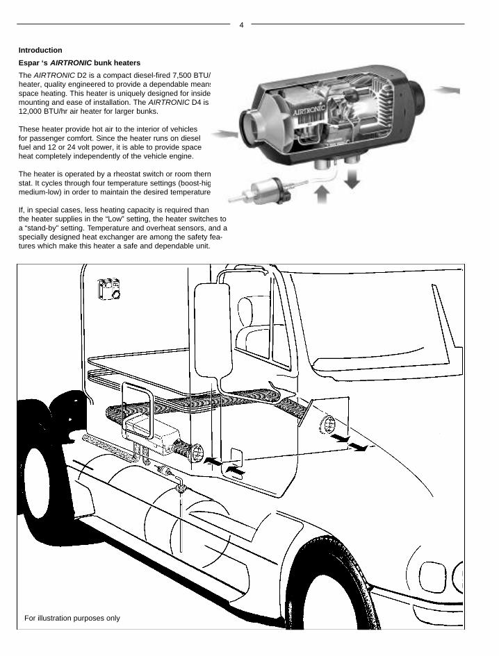
Introduction
Espar ‘s AIRTRONIC bunk heaters
The AIRTRONIC D2 is a compact diesel-fired 7,500 BTU/hr airheater, quality engineered to provide a dependable means ofspace heating. This heater is uniquely designed for insidemounting and ease of installation. The AIRTRONIC D4 is a12,000 BTU/hr air heater for larger bunks.
These heater provide hot air to the interior of vehiclesfor passenger comfort. Since the heater runs on dieselfuel and 12 or 24 volt power, it is able to provide spaceheat completely independently of the vehicle engine.
The heater is operated by a rheostat switch or room thermo-stat. It cycles through four temperature settings (boost-high-medium-low) in order to maintain the desired temperature.
If, in special cases, less heating capacity is required thanthe heater supplies in the “Low” setting, the heater switches toa “stand-by” setting. Temperature and overheat sensors, and aspecially designed heat exchanger are among the safety fea-tures which make this heater a safe and dependable unit.
For illustration purposes only
5
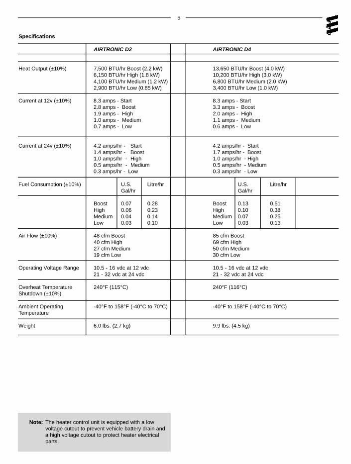
Note: The heater control unit is equipped with a lowvoltage cutout to prevent vehicle battery drain anda high voltage cutout to protect heater electrical parts.
Specifications
AIRTRONIC D2 AIRTRONIC D4
Heat Output (±10%) 7,500 BTU/hr Boost (2.2 kW) 13,650 BTU/hr Boost (4.0 kW)6,150 BTU/hr High (1.8 kW) 10,200 BTU/hr High (3.0 kW)4,100 BTU/hr Medium (1.2 kW) 6,800 BTU/hr Medium (2.0 kW)2,900 BTU/hr Low (0.85 kW) 3,400 BTU/hr Low (1.0 kW)
Current at 12v (±10%) 8.3 amps - Start 8.3 amps - Start2.8 amps - Boost 3.3 amps - Boost1.9 amps - High 2.0 amps - High1.0 amps - Medium 1.1 amps - Medium0.7 amps - Low 0.6 amps - Low
Current at 24v (±10%) 4.2 amps/hr - Start 4.2 amps/hr - Start1.4 amps/hr - Boost 1.7 amps/hr - Boost1.0 amps/hr - High 1.0 amps/hr - High0.5 amps/hr - Medium 0.5 amps/hr - Medium0.3 amps/hr - Low 0.3 amps/hr - Low
Fuel Consumption (±10%) U.S. Litre/hr U.S. Litre/hrGal/hr Gal/hr
Air Flow (±10%) 48 cfm Boost 85 cfm Boost40 cfm High 69 cfm High27 cfm Medium 50 cfm Medium19 cfm Low 30 cfm Low
Operating Voltage Range 10.5 - 16 vdc at 12 vdc 10.5 - 16 vdc at 12 vdc21 - 32 vdc at 24 vdc 21 - 32 vdc at 24 vdc
Overheat Temperature 240°F (115°C) 240°F (116°C)Shutdown (±10%)
Ambient Operating -40°F to 158°F (-40°C to 70°C) -40°F to 158°F (-40°C to 70°C)Temperature
Weight 6.0 lbs. (2.7 kg) 9.9 lbs. (4.5 kg)
6
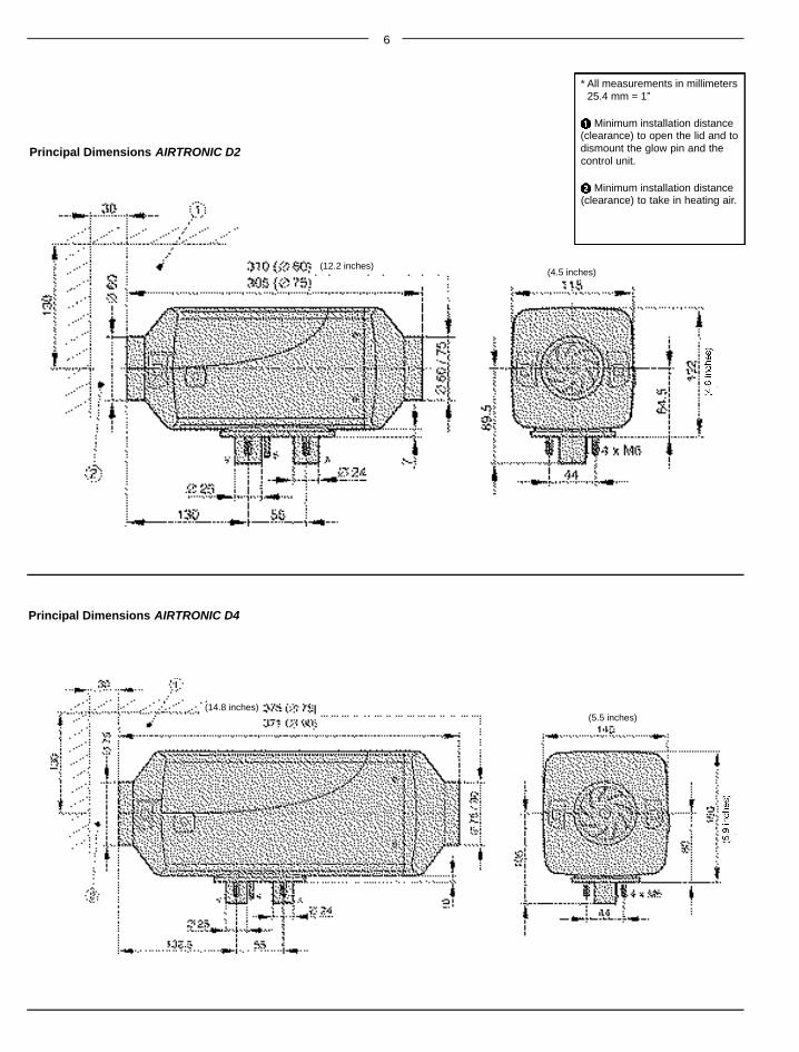
Principal Dimensions AIRTRONIC D2
Principal Dimensions AIRTRONIC D4
* All measurements in millimeters25.4 mm = 1”
Minimum installation distance(clearance) to open the lid and todismount the glow pin and thecontrol unit.
Minimum installation distance(clearance) to take in heating air.
(12.2 inches)
(14.8 inches)(5.5 inches)
(4.5 inches)
7
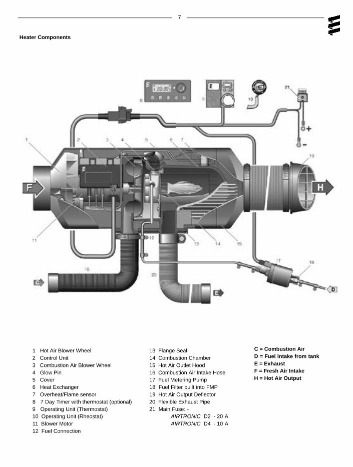
1 Hot Air Blower Wheel2 Control Unit3 Combustion Air Blower Wheel4 Glow Pin5 Cover6 Heat Exchanger7 Overheat/Flame sensor8 7 Day Timer with thermostat (optional)9 Operating Unit (Thermostat)10 Operating Unit (Rheostat)11 Blower Motor 12 Fuel Connection
13 Flange Seal14 Combustion Chamber15 Hot Air Outlet Hood16 Combustion Air Intake Hose17 Fuel Metering Pump18 Fuel Filter built into FMP19 Hot Air Output Deflector20 Flexible Exhaust Pipe21 Main Fuse: -
AIRTRONIC D2 - 20 AAIRTRONIC D4 - 10 A
Heater Components
C = Combustion AirD = Fuel Intake from tankE = ExhaustF = Fresh Air IntakeH = Hot Air Output
NutSpring Washer
Silicon gasket (flange)Stainless Steel PlatePlate seal
Cab Floor
8
Installation Procedures
Heater Location
Depending on the type of vehicle, the best location for mount-ing the heater will vary. Typically, air heaters are mountedinside tool or luggage compartments. However, the heater maybe mounted anywhere inside the vehicle provided you adhereto the following conditions:
• Combustion air intake, exhaust and fuel inlet must be located outside of the vehicle.
• Heater must be mounted on flat horizontal surfaceproviding an air tight seal between heater and vehicle.
• Do not mount the heater outside the vehicle, unless care istaken to protect the heater from the weather. When selectingthe location, consider the following:
• Combustion air and exhaust connections.• Ducting.• Fuel line connections.• Electrical connections.
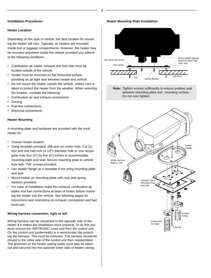
Heater Mounting
A mounting plate and hardware are provided with the truckheater kit.
• Choose heater location.• Using template provided, drill and cut center hole. Cut (1)
four and one half inch (4 1/2”) diameter hole or one rectan-gular hole four (4”) by five (5”) inches to accommodatemounting plate and seal. Secure mounting plate to vehiclefloor with “Tek” screws provided.
• Use Heater flange as a template if not using mounting plateand seal
• Mount heater on mounting plate with nuts and spring washers provided.
• For ease of installation make the exhaust, combustion airintake and fuel connections at base of heater before mount-ing the heater into the vehicle. See following pages forinstructions and restrictions on exhaust, combustion and fuelhook-ups.
Wiring harness connection, right or left
Wiring harness can be converted to the opposite side of theheater if it makes the installation more practical. To do this youmust remove the AIRTRONIC cover and then the control unit.On the control unit (underneath) is a semicircular clip protect-ing the harness. This must be removed. The harness should bemoved to the other side of the control unit then reassembled.The grommet on the heater casing (side) must also be takenout and secured into the opposite lower side of heater casing.
Note: Tighten screws sufficiently to ensure positive seal between mounting plate and mounting surface. Do not over tighten.
Heater Mounting Plate Installation
Hex Head Tek Screw
Flat washer
Wiring HarnessRight or Left
HeaterFlange
Stainless SteelMounting Plateand seal
CombustionAir intake
ExhaustTubing
Fuel line
9
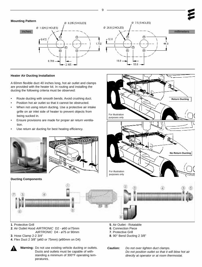
Warning: Do not use existing vehicle ducting or outlets.Ducts and outlets must be capable of with-standing a minimum of 300°F operating tem-peratures.
Caution: Do not over tighten duct clamps.Do not position outlet so that it will blow hot airdirectly at operator or at room thermostat.
1. Protective Grill 5. Air Outlet - Rotatable2. Air Outlet Hood AIRTRONIC D2 - ø60 or75mm 6. Connection Piece
AIRTRONIC D4 - ø75 or 90mm 7. Protective Grill3. Hose Clamp 2-2 3/4” 8. 90° Bend Ducting 2 3/8”4. Flex Duct 2 3/8” (ø60 or 75mm) (ø90mm on D4)
Heater Air Ducting Installation
A 60mm flexible duct 40 inches long, hot air outlet and clampsare provided with the heater kit. In routing and installing theducting the following criteria must be observed:
• Route ducting with smooth bends. Avoid crushing duct.• Position hot air outlet so that it cannot be obstructed.• When not using return ducting. Use a protective air intake
grille on air inlet side of heater to prevent objects frombeing sucked in.
• Ensure provisions are made for proper air return ventila-tion.
• Use return air ducting for best heating efficiency.
Return Ducting
No Return Ducting
Mounting Pattern
inches millimeters
Ducting Components
For illustrationpurposes only
For illustrationpurposes only
10
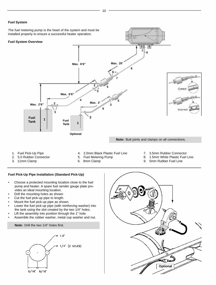
Fuel Pick-Up Pipe Installation (Standard Pick-Up)
• Choose a protected mounting location close to the fuel pump and heater. A spare fuel sender gauge plate pro-vides an ideal mounting location.
• Drill the mounting holes as shown• Cut the fuel pick-up pipe to length.• Mount the fuel pick-up pipe as shown.• Lower the fuel pick-up pipe (with reinforcing washer) into
the tank using the slot created by the two 1/4” holes.• Lift the assembly into position through the 1” hole.• Assemble the rubber washer, metal cup washer and nut.
7. 3.5mm Rubber Connector8. 1.5mm White Plastic Fuel Line9. 5mm Rubber Fuel Line
Max. 2’6”
FuelTank Fuel
Tank
Max. 2’
Max. 6’6”
1
2
2
3
3
5
6
7
8
67
4
3
93
5
1
Max. 20’
Max. 6’6”
Fuel System
The fuel metering pump is the heart of the system and must beinstalled properly to ensure a successful heater operation.
Fuel System Overview
Optional
11
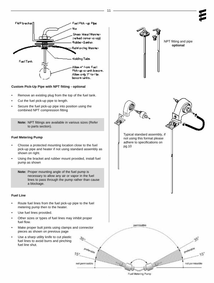
Fuel Metering Pump
• Choose a protected mounting location close to the fuelpick-up pipe and heater if not using standard assembly asshown on right.
• Using the bracket and rubber mount provided, install fuelpump as shown
Note: Proper mounting angle of the fuel pump isnecessary to allow any air or vapor in the fuel lines to pass through the pump rather than cause a blockage.
Fuel Line
• Route fuel lines from the fuel pick-up pipe to the fuel metering pump then to the heater.
• Use fuel lines provided.
• Other sizes or types of fuel lines may inhibit proper fuel flow.
• Make proper butt joints using clamps and connector pieces as shown on previous page
• Use a sharp utility knife to cut plastic fuel lines to avoid burrs and pinchingfuel line shut.
Custom Pick-Up Pipe with NPT fitting - optional
• Remove an existing plug from the top of the fuel tank.
• Cut the fuel pick-up pipe to length.
• Secure the fuel pick-up pipe into position using thecombined NPT compression fitting
NPT fitting and pipeoptional
Note: NPT fittings are available in various sizes (Refer to parts section).
Typical standard assembly, ifnot using this format pleaseadhere to specifications onpg.10
12
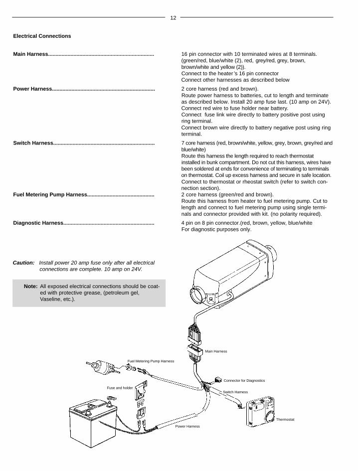
Electrical Connections
Main Harness....................................................................... 16 pin connector with 10 terminated wires at 8 terminals.(green/red, blue/white (2), red, grey/red, grey, brown,brown/white and yellow (2)).Connect to the heater ’s 16 pin connectorConnect other harnesses as described below
Power Harness..................................................................... 2 core harness (red and brown).Route power harness to batteries, cut to length and terminateas described below. Install 20 amp fuse last. (10 amp on 24V).Connect red wire to fuse holder near battery.Connect fuse link wire directly to battery positive post using ring terminal. Connect brown wire directly to battery negative post using ring terminal.
Switch Harness.................................................................... 7 core harness (red, brown/white, yellow, grey, brown, grey/red andb l u e / w h i t e )Route this harness the length required to reach thermostatinstalled in bunk compartment. Do not cut this harness, wires havebeen soldered at ends for convenience of terminating to terminalson thermostat. Coil up excess harness and secure in safe location.Connect to thermostat or rheostat switch (refer to switch con-nection section).
Fuel Metering Pump Harness............................................. 2 core harness (green/red and brown).Route this harness from heater to fuel metering pump. Cut tolength and connect to fuel metering pump using single termi-nals and connector provided with kit. (no polarity required).
Note: All exposed electrical connections should be coat-ed with protective grease, (petroleum gel,Vaseline, etc.).
Main Harness
Thermostat
Switch Harness
Connector for Diagnostics
Fuel Metering Pump Harness
Fuse and holder
Power Harness
Caution: Install power 20 amp fuse only after all electricalconnections are complete. 10 amp on 24V.
13
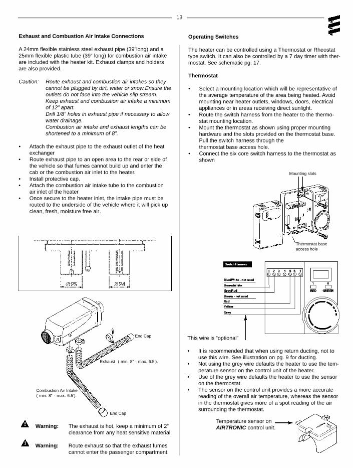
Warning: The exhaust is hot, keep a minimum of 2” clearance from any heat sensitive material
Warning: Route exhaust so that the exhaust fumes cannot enter the passenger compartment.
Exhaust and Combustion Air Intake Connections
A 24mm flexible stainless steel exhaust pipe (39”long) and a25mm flexible plastic tube (39” long) for combustion air intakeare included with the heater kit. Exhaust clamps and holdersare also provided.
Caution: Route exhaust and combustion air intakes so theycannot be plugged by dirt, water or snow.Ensure theoutlets do not face into the vehicle slip stream.Keep exhaust and combustion air intake a minimumof 12” apart.Drill 1/8” holes in exhaust pipe if necessary to allowwater drainage.Combustion air intake and exhaust lengths can beshortened to a minimum of 8”.
• Attach the exhaust pipe to the exhaust outlet of the heat exchanger
• Route exhaust pipe to an open area to the rear or side ofthe vehicle so that fumes cannot build up and enter thecab or the combustion air inlet to the heater.
• Install protective cap.• Attach the combustion air intake tube to the combustion
air inlet of the heater• Once secure to the heater inlet, the intake pipe must be
routed to the underside of the vehicle where it will pick upclean, fresh, moisture free air.
Exhaust ( min. 8” - max. 6.5’).
End Cap
End Cap
Operating Switches
The heater can be controlled using a Thermostat or Rheostattype switch. It can also be controlled by a 7 day timer with ther-mostat. See schematic pg. 17.
Thermostat
• Select a mounting location which will be representative ofthe average temperature of the area being heated. Avoidmounting near heater outlets, windows, doors, electricalappliances or in areas receiving direct sunlight.
• Route the switch harness from the heater to the thermo-stat mounting location.
• Mount the thermostat as shown using proper mountinghardware and the slots provided on the thermostat base.Pull the switch harness through thethermostat base access hole.
• Connect the six core switch harness to the thermostat asshown
Combustion Air Intake( min. 8” - max. 6.5’).
This wire is “optional”
• It is recommended that when using return ducting, not touse this wire. See illustration on pg. 9 for ducting.
• Not using the grey wire defaults the heater to use the tem-perature sensor on the control unit of the heater.
• Use of the grey wire defaults the heater to use the sensoron the thermostat.
• The sensor on the control unit provides a more accuratereading of the overall air temperature, whereas the sensorin the thermostat gives more of a spot reading of the airsurrounding the thermostat.
Thermostat baseaccess hole
Mounting slots
Temperature sensor onAIRTRONIC control unit.
14
Heater Operation
Warning: To prevent fire, the heater must be switchedoff while filling fuel tanks.To prevent asphyxiation, the heater must notbe operated in enclosed areas unless heatexhaust is routed to outside of garage bay.
1 Switch On
• Switch the heater on using the room thermostat’s, On/Offswitch (1=On, 0=Off ) or the rheostat switch.
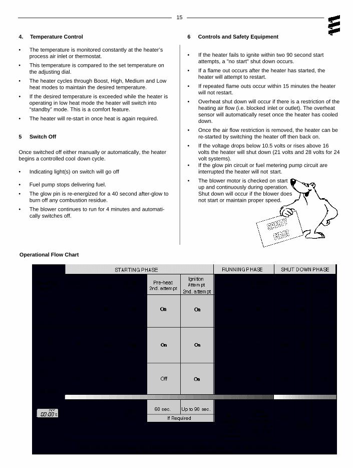
2 Start Up
On start up the indicator light illuminates and the followingsequences take place:
• Control unit does a systems check of the glow pin, flamesensor/temperature sensor, fuel metering pump and con-trol unit.
• Blower starts slowly and begins to accelerate.
• Glow pin is energized and starts preheating the combus-tion chamber.
• After a delay (approx. 60 seconds) the fuel pump deliversfuel.
• Ignition will take place as the fuel/air mixture contact theglow pin.
• Blower speed and fuel delivery are slowly increased.
• Once flame sensor has detected a flame the glow pin willswitch off, after approx. 60 secs.
• After another 120 secs., heater will have reached maxi-mum power.
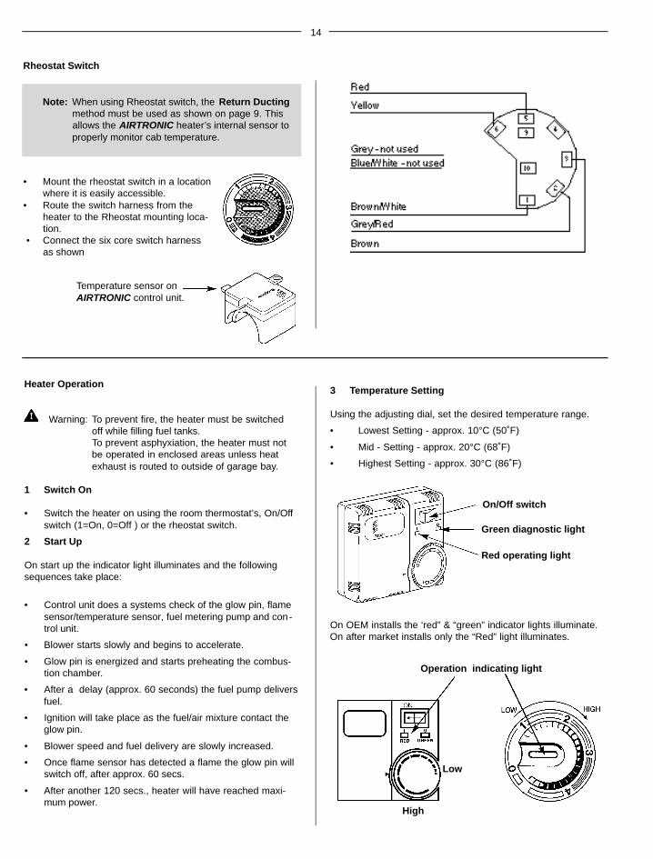
3 Temperature Setting
Using the adjusting dial, set the desired temperature range.
• Lowest Setting - approx. 10°C (50˚F)
• Mid - Setting - approx. 20°C (68˚F)
• Highest Setting - approx. 30°C (86˚F)
Operation indicating light
High
Low
Rheostat Switch
Note: When using Rheostat switch, the Return Ductingmethod must be used as shown on page 9. Thisallows the AIRTRONIC heater’s internal sensor toproperly monitor cab temperature.
• Mount the rheostat switch in a locationwhere it is easily accessible.
• Route the switch harness from theheater to the Rheostat mounting loca-tion.
• Connect the six core switch harnessas shown
On/Off switch
Red operating light
Green diagnostic light
On OEM installs the ‘red” & “green” indicator lights illuminate.On after market installs only the “Red” light illuminates.
Temperature sensor onAIRTRONIC control unit.
15
Operational Flow Chart
4. Temperature Control
• The temperature is monitored constantly at the heater’sprocess air inlet or thermostat.
• This temperature is compared to the set temperature onthe adjusting dial.
• The heater cycles through Boost, High, Medium and Lowheat modes to maintain the desired temperature.
• If the desired temperature is exceeded while the heater isoperating in low heat mode the heater will switch into“standby” mode. This is a comfort feature.
• The heater will re-start in once heat is again required.
5 Switch Off
Once switched off either manually or automatically, the heaterbegins a controlled cool down cycle.
• Indicating light(s) on switch will go off
• Fuel pump stops delivering fuel.
• The glow pin is re-energized for a 40 second after-glow toburn off any combustion residue.
• The blower continues to run for 4 minutes and automati-cally switches off.
6 Controls and Safety Equipment
• If the heater fails to ignite within two 90 second startattempts, a "no start" shut down occurs.
• If a flame out occurs after the heater has started, theheater will attempt to restart.
• If repeated flame outs occur within 15 minutes the heaterwill not restart.
• Overheat shut down will occur if there is a restriction of theheating air flow (i.e. blocked inlet or outlet). The overheatsensor will automatically reset once the heater has cooleddown.
• Once the air flow restriction is removed, the heater can bere-started by switching the heater off then back on.
• If the voltage drops below 10.5 volts or rises above 16volts the heater will shut down (21 volts and 28 volts for 24volt systems).
• If the glow pin circuit or fuel metering pump circuit areinterrupted the heater will not start.
• The blower motor is checked on startup and continuously during operation.Shut down will occur if the blower doesnot start or maintain proper speed.
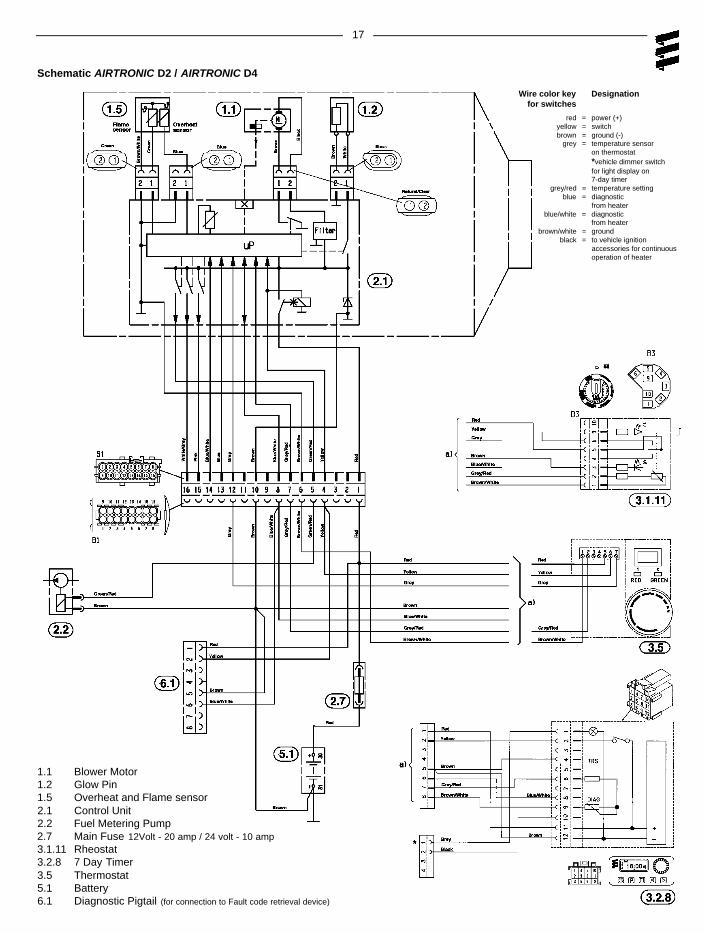
black = to vehicle ignitionaccessories for continuousoperation of heater
17
Schematic AIRTRONIC D2 / AIRTRONIC D4
1.1 Blower Motor1.2 Glow Pin1.5 Overheat and Flame sensor2.1 Control Unit2.2 Fuel Metering Pump2.7 Main Fuse 12Volt - 20 amp / 24 volt - 10 amp3.1.11 Rheostat3.2.8 7 Day Timer3.5 Thermostat5.1 Battery 6.1 Diagnostic Pigtail (for connection to Fault code retrieval device)
18
Maintenance
Recommended Periodic Maintenance
• Remove the glow pin and inspect for carbon build up.Clean or replace.
• Remove the glow pin screen and inspect for carbon buildup. Clean or replace.
• Make sure vent hole is open. Espar recommends the useof non detergent 100% volatile carburetor cleaner, an airgun will also help. Remove loose carbon from the glow pinchamber.
• Inspect the ducting, the air intake screen and air outlet forrestriction or blockage.
• Inspect combustion air intake and exhaust for blockage.
• Operate your heater for a minimum of 20 minutes eachmonth
• Maintain your batteries and all electrical connections ingood condition. With insufficient power the heater will notstart. Low and high voltage cutouts will shut the heaterdown automatically.
• Use fuel suitable for the climate (see engine manufac-turers recommendations). Blending used engine oil withdiesel fuel is not permitted.
Basic Troubleshooting
Check LIst:
What happens when the heater is switched on and ....
Heater does not ignite
1 Blower motor does not run
Check: - Fuse in power harness.
- Power to control unit.
- Power to and from switch.
- Electrical connections.
2 Blower motor runs approximately 20 seconds and thenshuts off
Check: - Ensure voltage at control unit remains above 10 volts during start up with glow plug circuit on.
3 Blower motor runs/fuel metering pump starts and then shuts down after two start up attempts
Check: - Fuel lines and fuel filter.
- Fuel quantity. Pg. 23
- Combustion air or exhaust tube blockage.
4 Blower motor runs/ no fuel metering pump
Check: - For electrical pulses at fuel metering pump.
- If pump is frozen.
- Blocked fuel line.
Heater ignites
1 Shuts down at random
Check: - Fuel metering pump quantity. Pg. 23
- Possible overheat.
- Control unit input voltage.
2 Heater smokes and carbons up
Check: - Exhaust pipe blocked.
- Combustion air intake blocked.
- Exhaust entering combustion air intake pipe.
- Short cycling, rapid on/off operation.
- Fuel system.
- Fuel metering pump quantity.
- Motor rpm.
Self Diagnostics
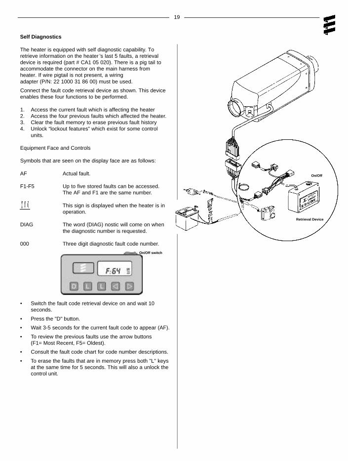
The heater is equipped with self diagnostic capability. Toretrieve information on the heater ’s last 5 faults, a retrievaldevice is required (part # CA1 05 020). There is a pig tail toaccommodate the connector on the main harness fromheater. If wire pigtail is not present, a wiringadapter (P/N: 22 1000 31 86 00) must be used.
Connect the fault code retrieval device as shown. This deviceenables these four functions to be performed.
1. Access the current fault which is affecting the heater2. Access the four previous faults which affected the heater.3. Clear the fault memory to erase previous fault history4. Unlock “lockout features” which exist for some control
units.
Equipment Face and Controls
Symbols that are seen on the display face are as follows:
AF Actual fault.
F1-F5 Up to five stored faults can be accessed. The AF and F1 are the same number.
This sign is displayed when the heater is in operation.
DIAG The word (DIAG) nostic will come on when the diagnostic number is requested.
000 Three digit diagnostic fault code number.
• Switch the fault code retrieval device on and wait 10seconds.
• Press the "D" button.
• Wait 3-5 seconds for the current fault code to appear (AF).
• To review the previous faults use the arrow buttons(F1= Most Recent, F5= Oldest).
• Consult the fault code chart for code number descriptions.
• To erase the faults that are in memory press both "L" keysat the same time for 5 seconds. This will also a unlock thecontrol unit.
19
Retrieval Device
On/Off
On/Off switch
20
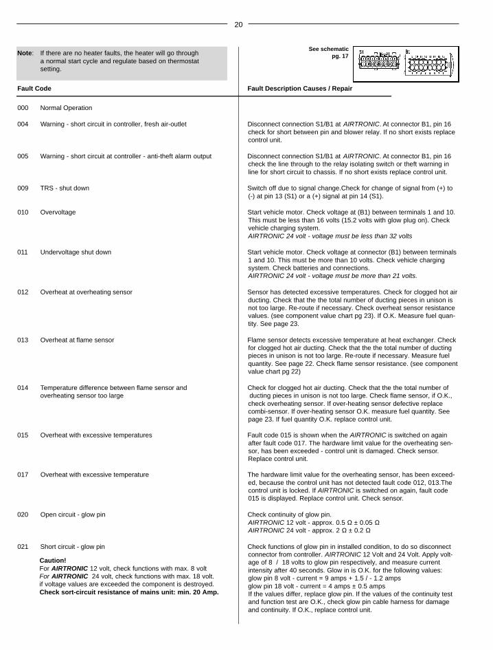
Note: If there are no heater faults, the heater will go througha normal start cycle and regulate based on thermostatsetting.
Fault Code Fault Description Causes / Repair
000 Normal Operation
004 Warning - short circuit in controller, fresh air-outlet Disconnect connection S1/B1 at AIRTRONIC. At connector B1, pin 16check for short between pin and blower relay. If no short exists replacecontrol unit.
005 Warning - short circuit at controller - anti-theft alarm output Disconnect connection S1/B1 at AIRTRONIC. At connector B1, pin 16check the line through to the relay isolating switch or theft warning inline for short circuit to chassis. If no short exists replace control unit.
009 TRS - shut down Switch off due to signal change.Check for change of signal from (+) to(-) at pin 13 (S1) or a (+) signal at pin 14 (S1).
010 Overvoltage Start vehicle motor. Check voltage at (B1) between terminals 1 and 10.This must be less than 16 volts (15.2 volts with glow plug on). Checkvehicle charging system. AIRTRONIC 24 volt - voltage must be less than 32 volts
011 Undervoltage shut down Start vehicle motor. Check voltage at connector (B1) between terminals1 and 10. This must be more than 10 volts. Check vehicle chargingsystem. Check batteries and connections.AIRTRONIC 24 volt - voltage must be more than 21 volts.
012 Overheat at overheating sensor Sensor has detected excessive temperatures. Check for clogged hot airducting. Check that the the total number of ducting pieces in unison isnot too large. Re-route if necessary. Check overheat sensor resistancevalues. (see component value chart pg 23). If O.K. Measure fuel quan-tity. See page 23.
013 Overheat at flame sensor Flame sensor detects excessive temperature at heat exchanger. Checkfor clogged hot air ducting. Check that the the total number of ductingpieces in unison is not too large. Re-route if necessary. Measure fuelquantity. See page 22. Check flame sensor resistance. (see componentvalue chart pg 22)
014 Temperature difference between flame sensor and Check for clogged hot air ducting. Check that the the total number ofoverheating sensor too large ducting pieces in unison is not too large. Check flame sensor, if O.K.,
check overheating sensor. If over-heating sensor defective replacecombi-sensor. If over-heating sensor O.K. measure fuel quantity. Seepage 23. If fuel quantity O.K. replace control unit.
015 Overheat with excessive temperatures Fault code 015 is shown when the AIRTRONIC is switched on againafter fault code 017. The hardware limit value for the overheating sen-sor, has been exceeded - control unit is damaged. Check sensor.Replace control unit.
017 Overheat with excessive temperature The hardware limit value for the overheating sensor, has been exceed-ed, because the control unit has not detected fault code 012, 013.Thecontrol unit is locked. If AIRTRONIC is switched on again, fault code015 is displayed. Replace control unit. Check sensor.
020 Open circuit - glow pin Check continuity of glow pin. AIRTRONIC 12 volt - approx. 0.5 Ω ± 0.05 ΩAIRTRONIC 24 volt - approx. 2 Ω ± 0.2 Ω
021 Short circuit - glow pin Check functions of glow pin in installed condition, to do so disconnectconnector from controller. AIRTRONIC 12 Volt and 24 Volt. Apply volt-age of 8 / 18 volts to glow pin respectively, and measure currentintensity after 40 seconds. Glow in is O.K. for the following values:glow pin 8 volt - current = 9 amps + 1.5 / - 1.2 ampsglow pin 18 volt - current = 4 amps ± 0.5 ampsIf the values differ, replace glow pin. If the values of the continuity testand function test are O.K., check glow pin cable harness for damageand continuity. If O.K., replace control unit.
Caution!For AIRTRONIC 12 volt, check functions with max. 8 voltFor AIRTRONIC 24 volt, check functions with max. 18 volt.if voltage values are exceeded the component is destroyed.Check sort-circuit resistance of mains unit: min. 20 Amp.
See schematicpg. 17
21
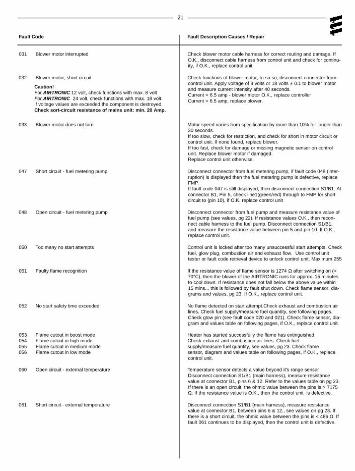
Fault Code Fault Description Causes / Repair
031 Blower motor interrupted Check blower motor cable harness for correct routing and damage. IfO.K., disconnect cable harness from control unit and check for continu-ity, if O.K., replace control unit.
032 Blower motor, short circuit Check functions of blower motor, to so so, disconnect connector fromcontrol unit. Apply voltage of 8 volts or 18 volts ± 0.1 to blower motorand measure current intensity after 40 seconds.Current < 6.5 amp - blower motor O.K., replace controllerCurrent > 6.5 amp, replace blower.
033 Blower motor does not turn Motor speed varies from specification by more than 10% for longer than30 seconds.If too slow, check for restriction, and check for short in motor circuit orcontrol unit. If none found, replace blower.If too fast, check for damage or missing magnetic sensor on controlunit. Replace blower motor if damaged.Replace control unit otherwise.
047 Short circuit - fuel metering pump Disconnect connector from fuel metering pump, if fault code 048 (inter-ruption) is displayed then the fuel metering pump is defective, replaceFMP.If fault code 047 is still displayed, then disconnect connection S1/B1. Atconnector B1, Pin 5, check line1(green/red) through to FMP for shortcircuit to (pin 10), if O.K. replace control unit
048 Open circuit - fuel metering pump Disconnect connector from fuel pump and measure resistance value offuel pump (see values, pg 22). If resistance values O.K., then recon-nect cable harness to the fuel pump. Disconnect connection S1/B1,and measure the resistance value between pin 5 and pin 10. If O.K.,replace control unit.
050 Too many no start attempts Control unit is locked after too many unsuccessful start attempts. Checkfuel, glow plug, combustion air and exhaust flow. Use control unittester or fault code retrieval device to unlock control unit. Maximum 255
051 Faulty flame recognition If the resistance value of flame sensor is 1274 Ω after switching on (>70°C), then the blower of the AIRTRONIC runs for approx. 15 minutesto cool down. If resistance does not fall below the above value within15 mins.., this is followed by fault shut down. Check flame sensor, dia-grams and values, pg 23. If O.K., replace control unit.
052 No start safety time exceeded No flame detected on start attempt.Check exhaust and combustion airlines. Check fuel supply/measure fuel quantity, see following pages.Check glow pin (see fault code 020 and 021). Check flame sensor, dia-gram and values table on following pages, if O.K., replace control unit.
053 Flame cutout in boost mode Heater has started successfully the flame has extinguished.054 Flame cutout in high mode Check exhaust and combustion air lines. Check fuel 055 Flame cutout in medium mode supply/measure fuel quantity, see values, pg 23. Check flame056 Flame cutout in low mode sensor, diagram and values table on following pages, if O.K., replace
control unit.
060 Open circuit - external temperature Temperature sensor detects a value beyond it's range sensorDisconnect connection S1/B1 (main harness), measure resistancevalue at connector B1, pins 6 & 12. Refer to the values table on pg 23.If there is an open circuit, the ohmic value between the pins is > 7175Ω. If the resistance value is O.K., then the control unit is defective.
061 Short circuit - external temperature Disconnect connection S1/B1 (main harness), measure resistancevalue at connector B1, between pins 6 & 12., see values on pg 23. Ifthere is a short circuit, the ohmic value between the pins is < 486 Ω. Iffault 061 continues to be displayed, then the control unit is defective.
Caution!For AIRTRONIC 12 volt, check functions with max. 8 voltFor AIRTRONIC 24 volt, check functions with max. 18 volt.if voltage values are exceeded the component is destroyed.Check sort-circuit resistance of mains unit: min. 20 Amp.
22
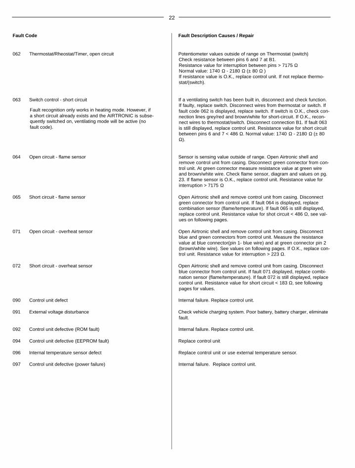
Fault Code Fault Description Causes / Repair
062 Thermostat/Rheostat/Timer, open circuit Potentiometer values outside of range on Thermostat (switch)Check resistance between pins 6 and 7 at B1.Resistance value for interruption between pins > 7175 ΩNormal value: 1740 Ω - 2180 Ω (± 80 Ω )If resistance value is O.K., replace control unit. If not replace thermo-stat/(switch).
063 Switch control - short circuit If a ventilating switch has been built in, disconnect and check function.If faulty, replace switch. Disconnect wires from thermostat or switch. Iffault code 062 is displayed, replace switch. If switch is O.K., check con-nection lines grey/red and brown/white for short-circuit. If O.K., recon-nect wires to thermostat/switch. Disconnect connection B1. If fault 063is still displayed, replace control unit. Resistance value for short circuitbetween pins 6 and 7 < 486 Ω. Normal value: 1740 Ω - 2180 Ω (± 80Ω).
064 Open circuit - flame sensor Sensor is sensing value outside of range. Open Airtronic shell andremove control unit from casing. Disconnect green connector from con-trol unit. At green connector measure resistance value at green wireand brown/white wire. Check flame sensor, diagram and values on pg.23. If flame sensor is O.K., replace control unit. Resistance value forinterruption > 7175 Ω
065 Short circuit - flame sensor Open Airtronic shell and remove control unit from casing. Disconnectgreen connector from control unit. If fault 064 is displayed, replacecombination sensor (flame/temperature). If fault 065 is still displayed,replace control unit. Resistance value for shot circuit < 486 Ω, see val-ues on following pages.
071 Open circuit - overheat sensor Open Airtronic shell and remove control unit from casing. Disconnectblue and green connectors from control unit. Measure the resistancevalue at blue connector(pin 1- blue wire) and at green connector pin 2(brown/white wire). See values on following pages. If O.K., replace con-trol unit. Resistance value for interruption > 223 Ω.
072 Short circuit - overheat sensor Open Airtronic shell and remove control unit from casing. Disconnectblue connector from control unit. If fault 071 displayed, replace combi-nation sensor (flame/temperature). If fault 072 is still displayed, replacecontrol unit. Resistance value for short circuit < 183 Ω, see followingpages for values.
090 Control unit defect Internal failure. Replace control unit.
092 Control unit defective (ROM fault) Internal failure. Replace control unit.
094 Control unit defective (EEPROM fault) Replace control unit
096 Internal temperature sensor defect Replace control unit or use external temperature sensor.
097 Control unit defective (power failure) Internal failure. Replace control unit.
Fault recognition only works in heating mode. However, ifa short circuit already exists and the AIRTRONIC is subse-quently switched on, ventilating mode will be active (nofault code).
23
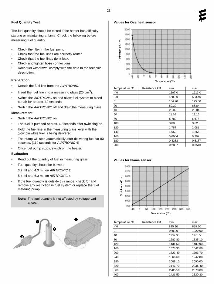
Fuel Quantity Test
The fuel quantity should be tested if the heater has difficultystarting or maintaining a flame. Check the following beforemeasuring fuel quantity.
• Check the filter in the fuel pump• Check that the fuel lines are correctly routed• Check that the fuel lines don’t leak.• Check and tighten hose connections• Does fuel withdrawal comply with the data in the technical
description.
Preparation
• Detach the fuel line from the AIRTRONIC.
• Insert the fuel line into a measuring glass (25 cm3).
• Switch the AIRTRONIC on and allow fuel system to bleedout air for approx. 60 seconds.
• Switch the AIRTRONIC off and drain the measuring glass.
Measurement
• Switch the AIRTRONIC on
• The fuel is pumped approx. 60 seconds after switching on.
• Hold the fuel line in the measuring glass level with theglow pin while fuel is being delivered.
• The pump will stop automatically after delivering fuel for 90seconds. (110 seconds for AIRTRONIC 4)
• Once fuel pump stops, switch off the heater.
Evaluation
• Read out the quantity of fuel in measuring glass.
• Fuel quantity should be between
3.7 ml and 4.3 ml. on AIRTRONIC 2
5.4 ml and 6.3 ml. on AIRTRONIC 4
• If the fuel quantity is outside this range, check for andremove any restriction in fuel system or replace the fuelmetering pump.
Note: The fuel quantity is not affected by voltage vari-ances.
Temperature °C Resistance kΩ min. max.
-40 1597.0 1913.0
-20 458.80 533.40
0 154.70 175.50
20 59.30 65.84
40 25.02 28.04
60 11.56 13.16
80 5.782 6.678
100 3.095 3.623
120 1.757 2.081
140 1.050 1.256
160 0.6654 0.792
180 0.4253 0.5187
200 0.2857 0.3513
Values for Overheat sensor
Temperature (°C)
Temperature °C Resistance kΩ min. max.
-40 825.90 859.60
0 980.00 1020.00
40 1132.30 1178.50
80 1282.80 1335.10
120 1431.50 1489.90
160 1578.30 1642.80
200 1723.40 1793.70
240 1866.60 1942.80
280 2008.10 2090.00
320 2147.70 2235.40
360 2285.50 2378.80
400 2421.50 2520.30
Values for Flame sensor
Temperature (°C)
24
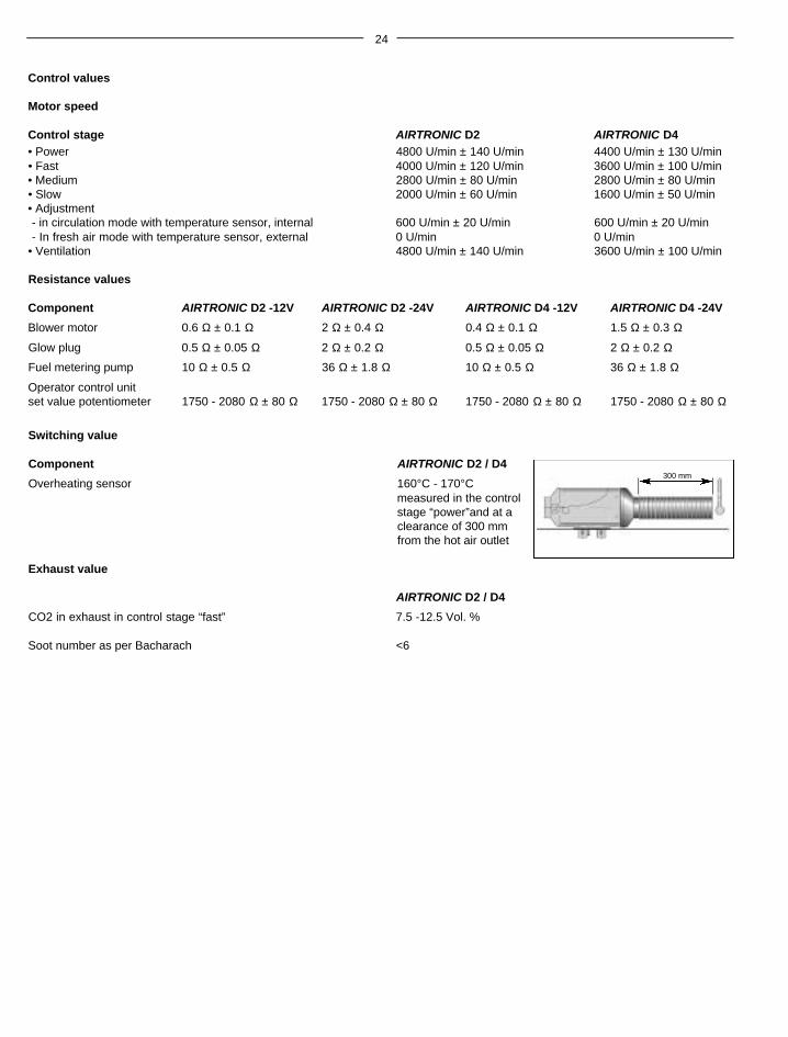
Control values
Motor speed
Control stage AIRTRONIC D2 AIRTRONIC D4• Power 4800 U/min ± 140 U/min 4400 U/min ± 130 U/min• Fast 4000 U/min ± 120 U/min 3600 U/min ± 100 U/min• Medium 2800 U/min ± 80 U/min 2800 U/min ± 80 U/min• Slow 2000 U/min ± 60 U/min 1600 U/min ± 50 U/min• Adjustment- in circulation mode with temperature sensor, internal 600 U/min ± 20 U/min 600 U/min ± 20 U/min- In fresh air mode with temperature sensor, external 0 U/min 0 U/min
Overheating sensor 160°C - 170°Cmeasured in the controlstage “power”and at aclearance of 300 mmfrom the hot air outlet
Exhaust value
AIRTRONIC D2 / D4
CO2 in exhaust in control stage “fast” 7.5 -12.5 Vol. %
Soot number as per Bacharach <6
300 mm
25
Repair Instructions
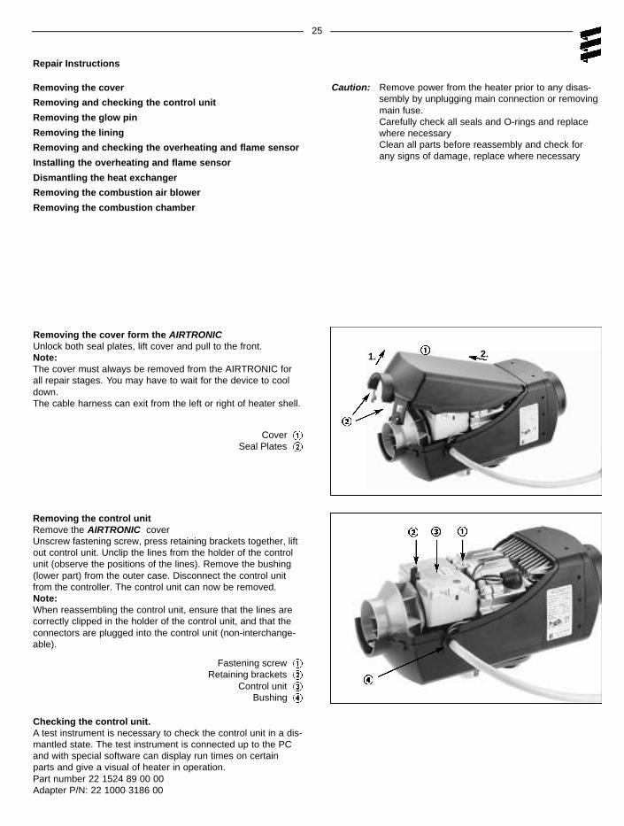
Removing the cover
Removing and checking the control unit
Removing the glow pin
Removing the lining
Removing and checking the overheating and flame sensor
Installing the overheating and flame sensor
Dismantling the heat exchanger
Removing the combustion air blower
Removing the combustion chamber
Removing the control unitRemove the AIRTRONIC coverUnscrew fastening screw, press retaining brackets together, liftout control unit. Unclip the lines from the holder of the controlunit (observe the positions of the lines). Remove the bushing(lower part) from the outer case. Disconnect the control unitfrom the controller. The control unit can now be removed.Note:When reassembling the control unit, ensure that the lines arecorrectly clipped in the holder of the control unit, and that theconnectors are plugged into the control unit (non-interchange-able).
Checking the control unit.A test instrument is necessary to check the control unit in a dis-mantled state. The test instrument is connected up to the PCand with special software can display run times on certainparts and give a visual of heater in operation.Part number 22 1524 89 00 00Adapter P/N: 22 1000 3186 00
Caution: Remove power from the heater prior to any disas-sembly by unplugging main connection or removingmain fuse. Carefully check all seals and O-rings and replacewhere necessaryClean all parts before reassembly and check forany signs of damage, replace where necessary
1. 2.
Cover Seal Plates
Fastening screw Retaining brackets
Control unit Bushing
Removing the cover form the AIRTRONICUnlock both seal plates, lift cover and pull to the front.Note:The cover must always be removed from the AIRTRONIC forall repair stages. You may have to wait for the device to cooldown.The cable harness can exit from the left or right of heater shell.
26
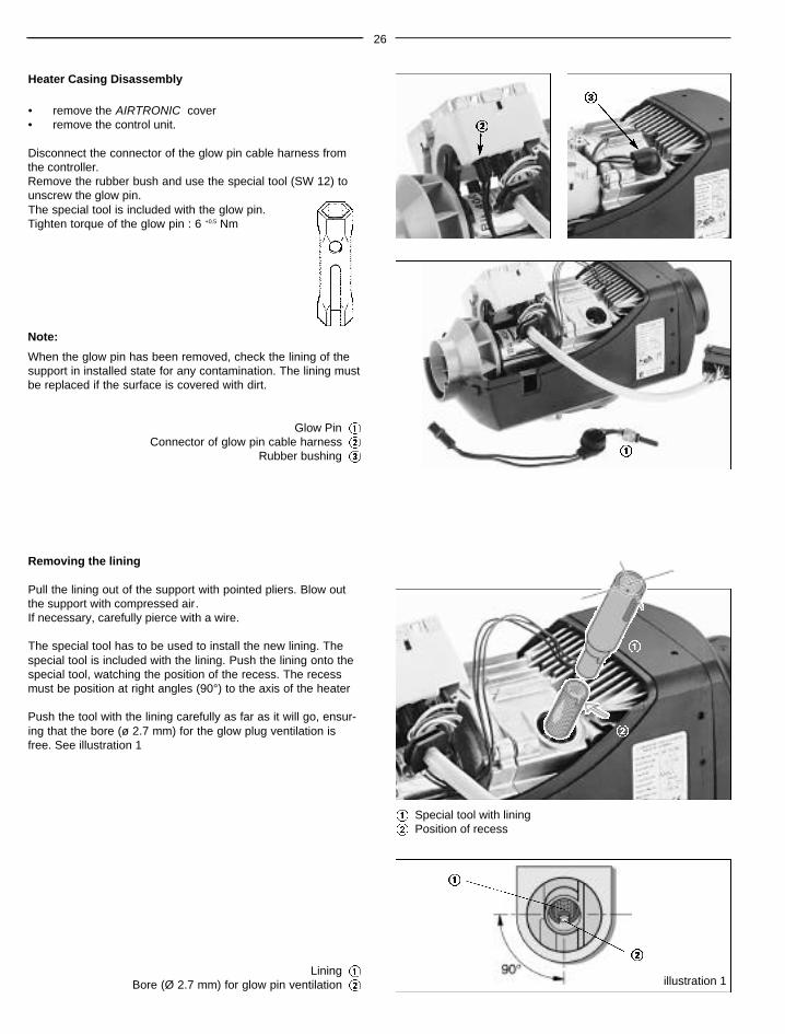
Heater Casing Disassembly
• remove the AIRTRONIC cover• remove the control unit.
Disconnect the connector of the glow pin cable harness fromthe controller.Remove the rubber bush and use the special tool (SW 12) tounscrew the glow pin.The special tool is included with the glow pin.Tighten torque of the glow pin : 6 +0.5 Nm
Note:
When the glow pin has been removed, check the lining of thesupport in installed state for any contamination. The lining mustbe replaced if the surface is covered with dirt.
Removing the lining
Pull the lining out of the support with pointed pliers. Blow outthe support with compressed air.If necessary, carefully pierce with a wire.
The special tool has to be used to install the new lining. Thespecial tool is included with the lining. Push the lining onto thespecial tool, watching the position of the recess. The recessmust be position at right angles (90°) to the axis of the heater
Push the tool with the lining carefully as far as it will go, ensur-ing that the bore (ø 2.7 mm) for the glow plug ventilation isfree. See illustration 1
Glow Pin Connector of glow pin cable harness
Rubber bushing
Special tool with liningPosition of recess
illustration 1Lining
Bore (Ø 2.7 mm) for glow pin ventilation
27
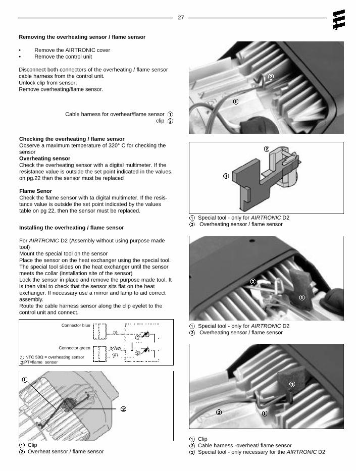
Removing the overheating sensor / flame sensor
• Remove the AIRTRONIC cover• Remove the control unit
Disconnect both connectors of the overheating / flame sensorcable harness from the control unit.Unlock clip from sensor.Remove overheating/flame sensor.
Cable harness for overhear/flame sensor clip
Special tool - only for AIRTRONIC D2Overheating sensor / flame sensor
Special tool - only for AIRTRONIC D2Overheating sensor / flame sensor
ClipCable harness -overheat/ flame sensorSpecial tool - only necessary for the AIRTRONIC D2
ClipOverheat sensor / flame sensor
Checking the overheating / flame sensorObserve a maximum temperature of 320° C for checking thesensorOverheating sensorCheck the overheating sensor with a digital multimeter. If theresistance value is outside the set point indicated in the values,on pg.22 then the sensor must be replaced
Flame SenorCheck the flame sensor with ta digital multimeter. If the resis-tance value is outside the set point indicated by the valuestable on pg 22, then the sensor must be replaced.
Installing the overheating / flame sensor
For AIRTRONIC D2 (Assembly without using purpose madetool)Mount the special tool on the sensorPlace the sensor on the heat exchanger using the special tool.The special tool slides on the heat exchanger until the sensormeets the collar (installation site of the sensor)Lock the sensor in place and remove the purpose made tool. Itis then vital to check that the sensor sits flat on the heatexchanger. If necessary use a mirror and lamp to aid correctassembly.Route the cable harness sensor along the clip eyelet to thecontrol unit and connect.
Connector blue
Connector green
NTC 50Ω = overheating sensorPT=flame sensor
28
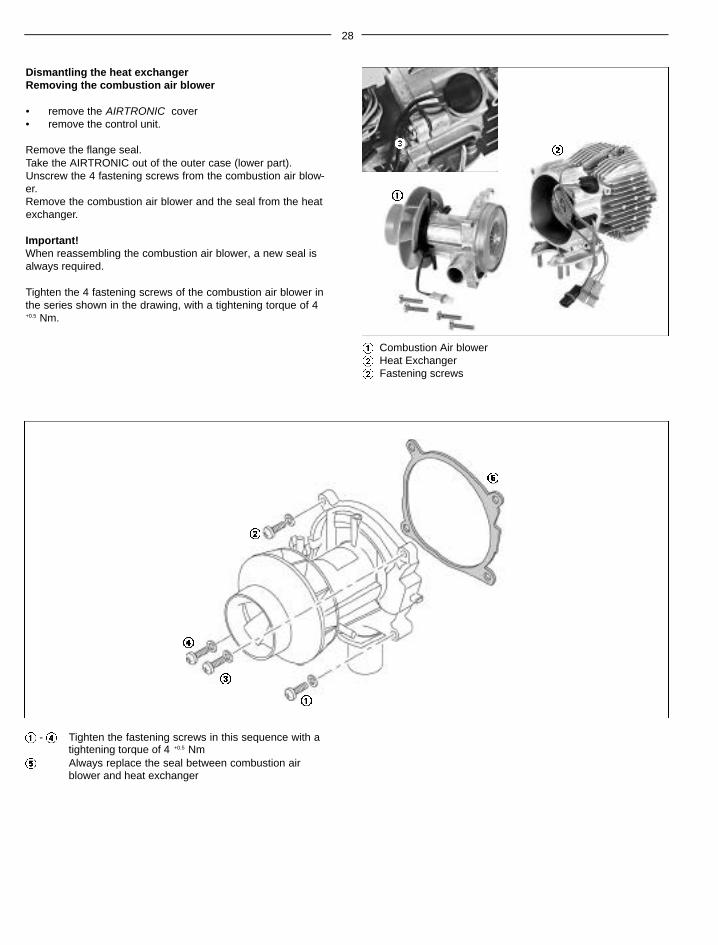
Dismantling the heat exchangerRemoving the combustion air blower
• remove the AIRTRONIC cover• remove the control unit.
Remove the flange seal.Take the AIRTRONIC out of the outer case (lower part).Unscrew the 4 fastening screws from the combustion air blow-er.Remove the combustion air blower and the seal from the heatexchanger.
Important!When reassembling the combustion air blower, a new seal isalways required.
Tighten the 4 fastening screws of the combustion air blower inthe series shown in the drawing, with a tightening torque of 4+0.5 Nm.
Combustion Air blowerHeat ExchangerFastening screws
- Tighten the fastening screws in this sequence with a tightening torque of 4 +0.5 NmAlways replace the seal between combustion airblower and heat exchanger
29
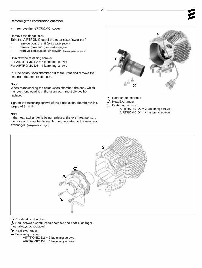
Removing the combustion chamber
• remove the AIRTRONIC cover
Remove the flange seal.Take the AIRTRONIC out of the outer case (lower part).• remove control unit (see previous pages)
• remove glow pin (see previous pages)
• remove combustion air blower (see previous pages)
Pull the combustion chamber out to the front and remove theseal from the heat exchanger.
Note!When reassembling the combustion chamber, the seal, whichhas been enclosed with the spare part, must always bereplaced.
Tighten the fastening screws of the combustion chamber with atorque of 5 +0.5 Nm.
Note:If the heat exchanger is being replaced, the over heat sensor /flame sensor must be dismantled and mounted to the new heatexchanger. (see previous pages)