38
ENGLISH V3100 Class B AIS Transponder User manual bandg.com simrad-yachting.com
ENGLISH
V3100 Class BAIS TransponderUser manual
bandg.com simrad-yachting.com

| 3Preface | V3100 User Manual
PrefaceAs Navico is continuously improving this product, we retain the right to make changes to the product at any time which may not be reflected in this version of the manual. Please contact your nearest distributor if you require any further assistance.
It is the owner’s sole responsibility to install and use the V3100 AIS Class B Transponder in a manner that will not cause accidents, per-sonal injury or property damage. The user of this product is solely responsible for observing safe boating practices.
NAVICO HOLDING AS AND ITS SUBSIDIARIES, BRANCHES AND AF-FILIATES DISCLAIM ALL LIABILITY FOR ANY USE OF THIS PRODUCT IN A WAY THAT MAY CAUSE ACCIDENTS, DAMAGE OR THAT MAY VIOLATE THE LAW.
Governing Language: This statement, any instruction manuals, user guides and other information relating to the product (Documenta-tion) may be translated to, or has been translated from, another language (Translation). In the event of any conflict between any Translation of the Documentation, the English language version will be the official version of the Documentation.
This manual represents the product as at the time of printing. Navico Holding AS and its subsidiaries, branches and affiliates re-serve the right to make changes to specifications without notice.
CopyrightCopyright © 2018 Navico Holding AS.
WarrantyThe warranty card is supplied as a separate document.
About this manualImportant text that requires special attention from the reader is emphasized as follows:
¼ Note: Used to draw the reader’s attention to a comment or some important information.
Warning: Used when it is necessary to warn personnel that they should proceed carefully to prevent risk of injury and/or damage to equipment/personnel.
4 | Contents | V3100 User Manual
Contents
3 Preface
5 Notices5 Safety warnings5 General notices
9 About your AIS class B transponder9 About AIS9 Product description10 Static and dynamic vessel data12 Important information for US customers 12 What’s in the box?
13 Installation13 Installation procedures
21 Configuring your AIS transponder21 Connecting to your AIS transponder23 Programming your vessel data
24 Get started24 LED indicators25 Micro SD card data logging25 Built-in integrity test (BIIT)
26 Specifications26 Product specifications29 Dimensions30 NMEA 2000 PGN information31 Supported NMEA 0183 sentences
32 Troubleshooting
34 Abbreviations
35 How to determine Serial Port
| 5Notices | V3100 User Manual
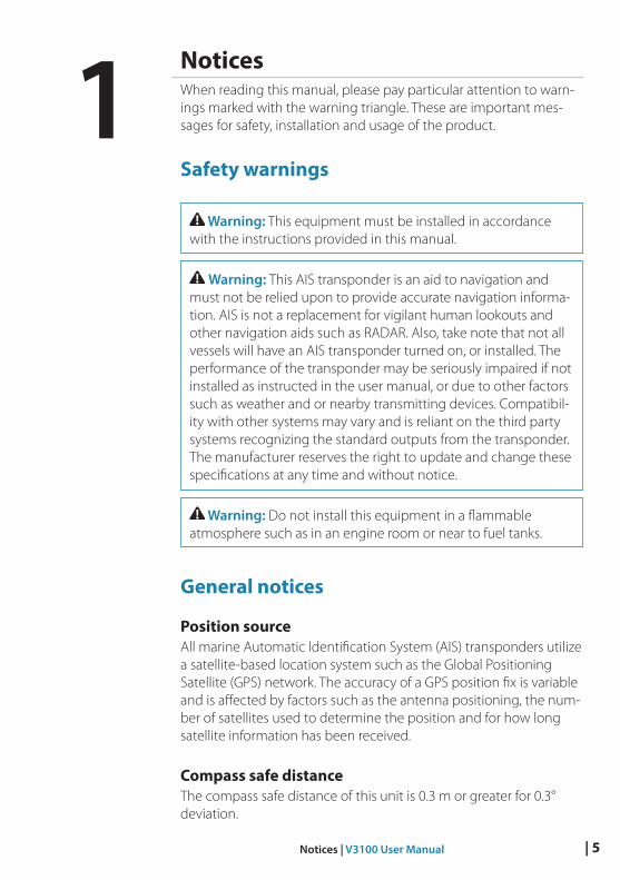
NoticesWhen reading this manual, please pay particular attention to warn-ings marked with the warning triangle. These are important mes-sages for safety, installation and usage of the product.
Safety warnings
Warning: This equipment must be installed in accordance with the instructions provided in this manual.
Warning: This AIS transponder is an aid to navigation and must not be relied upon to provide accurate navigation informa-tion. AIS is not a replacement for vigilant human lookouts and other navigation aids such as RADAR. Also, take note that not all vessels will have an AIS transponder turned on, or installed. The performance of the transponder may be seriously impaired if not installed as instructed in the user manual, or due to other factors such as weather and or nearby transmitting devices. Compatibil-ity with other systems may vary and is reliant on the third party systems recognizing the standard outputs from the transponder. The manufacturer reserves the right to update and change these specifications at any time and without notice.
Warning: Do not install this equipment in a flammable atmosphere such as in an engine room or near to fuel tanks.
General notices
Position sourceAll marine Automatic Identification System (AIS) transponders utilize a satellite-based location system such as the Global Positioning Satellite (GPS) network. The accuracy of a GPS position fix is variable and is affected by factors such as the antenna positioning, the num-ber of satellites used to determine the position and for how long satellite information has been received.
Compass safe distanceThe compass safe distance of this unit is 0.3 m or greater for 0.3° deviation.
1
6 | Notices | V3100 User Manual
RF emissions notice
¼ Note: The AIS transponder generates and radiates radio frequency electromagnetic energy. This equipment must be installed and oper-ated according to the instructions contained in this manual. Failure to do so can result in malfunctioning of the receiver or personal injury.
¼ Note: Never operate the AIS transponder unless it is connected to a VHF antenna. To maximize performance and minimize human exposure to radio frequency electromagnetic energy you must make sure that the an-tenna is mounted at least 1.5 meters away from the AIS transponder and is connected to the AIS transponder before power is applied.
The system has a Maximum Permissible Exposure (MPE) radius of 1.2 m. This has been determined assuming the maximum power of the AIS transponder and using antennas with a maximum gain of 3 db.
The antenna should be mounted 3.5 m above the deck in order to meet RF exposure requirements. Higher gain antennas will require a greater MPE radius. Do not operate the unit when anyone is within the MPE radius of the antenna (unless they are shielded from the an-tenna field by a grounded metallic barrier). The antenna should not be co-located or operated in conjunction with any other transmit-ting antenna. The required antenna impedance is 50 ohms.
WarrantyThis product is supplied with standard warranty as defined in the accompanying warranty information.
Warning: Any attempt to tamper with or damage the product will invalidate the warranty.
Disposal of this product and packagingPlease dispose of the AIS transponder in accordance with the European WEEE Directive or with the applicable local regulations for disposal of electrical equipment.
Every effort has been made to ensure the packaging for this product is recyclable. Please dispose of the packaging in an environmentally friendly manner.
Accuracy of this manualThe AIS transponder may be upgraded from time to time and future versions of the AIS transponder may therefore not correspond
| 7Notices | V3100 User Manual
exactly with this manual. Information contained in this manual is liable to change without notice. The manufacturer of this product disclaims any liability for consequences arising from omissions or inaccuracies in this manual and any other documentation provided with this product.
Declaration of conformityThe manufacturer of this product declares that this product is in compliance with the essential requirements and other provisions of the 2014/53/EU Directive. The declaration of conformity is provided with the product document pack. The product carries the CE mark, notified body number and alert symbol as required by the 2014/53/EU Directive. The product is intended for sale in the countries listed under Specifications.
FCC noticeThis equipment has been tested and found to comply with the lim-its for a class B digital device, pursuant to part 15 of the FCC Rules.These limits are designed to provide reasonable protection against harmful interference in a residential installation. This equipment generates, uses and can radiate radio frequency energy and, if not installed and used in accordance with the instructions, may cause harmful interference to radio communications. This device complies with part 15 of the FCC Rules. Operation is subject to the following two conditions: (1) This device may not cause harmful interference, and (2) this device must accept any interference received, includ-ing interference that may cause undesired operation. Changes or modifications not expressly approved by the party responsible for compliance could void the user’s authority to operate the equip-ment.
Warning: It is a violation of the rules of the Federal Communi-cations Commission to input an MMSI that has not been properly assigned to the end user, or to otherwise input any inaccurate data in this device.
8 | Notices | V3100 User Manual
Industry Canada noticeThis device complies with Industry Canada license-exempt RSS standard(s). Operation is subject to the following two conditions:
1. This device may not cause interference, and
2. This device must accept any interference, including interference that may cause undesired operation of the device.
This Class B digital apparatus complies with Canadian ICES-003.
Le présent appareil est conforme aux CNR d’Industrie Canada applicables aux appareils radio exempts de licence. L’exploitation est autorisée aux deux conditions suivantes :
1. L’appareil ne doit pas produire de brouillage, et
2. L’utilisateur de l’appareil doit accepter tout brouillage radioélectrique subi, même si le brouillage est susceptible d’en compromettre le Fonctionne-ment.
Cet appareil numérique de la classe B est conforme à la norme NMB-003 du Canada.
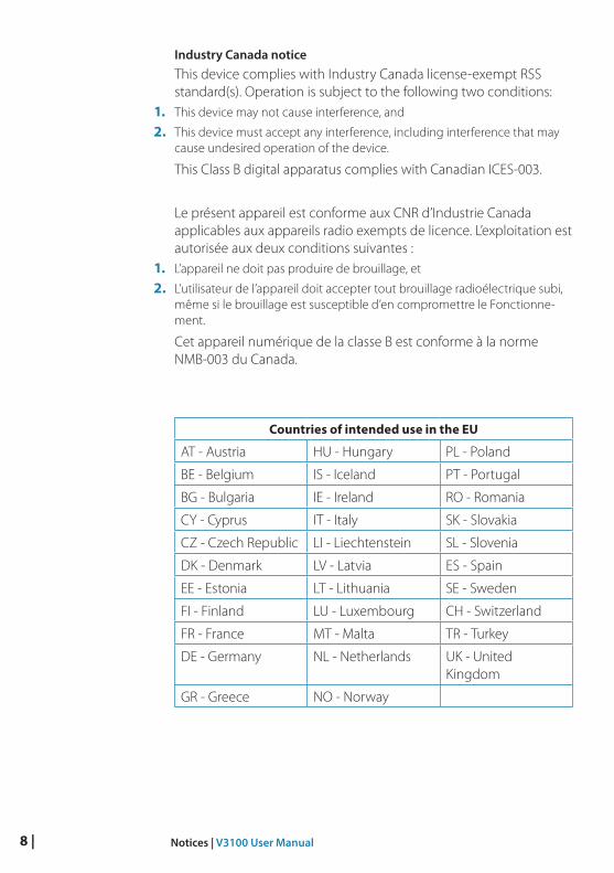
Countries of intended use in the EU
AT - Austria HU - Hungary PL - Poland
BE - Belgium IS - Iceland PT - Portugal
BG - Bulgaria IE - Ireland RO - Romania
CY - Cyprus IT - Italy SK - Slovakia
CZ - Czech Republic LI - Liechtenstein SL - Slovenia
DK - Denmark LV - Latvia ES - Spain
EE - Estonia LT - Lithuania SE - Sweden
FI - Finland LU - Luxembourg CH - Switzerland
FR - France MT - Malta TR - Turkey
DE - Germany NL - Netherlands UK - United Kingdom
GR - Greece NO - Norway
| 9About your AIS class B transponder | V3100 User Manual
About your AIS class B transponder
About AISThe marine Automatic Identification System (AIS) is a location and vessel information reporting system. It allows vessels equipped with AIS to automatically and dynamically share and regularly update their position, speed, course and other information such as vessel identity with similarly equipped vessels. Position is derived from the Global Positioning System (GPS) and communication between ves-sels is by Very High Frequency (VHF) digital transmissions.
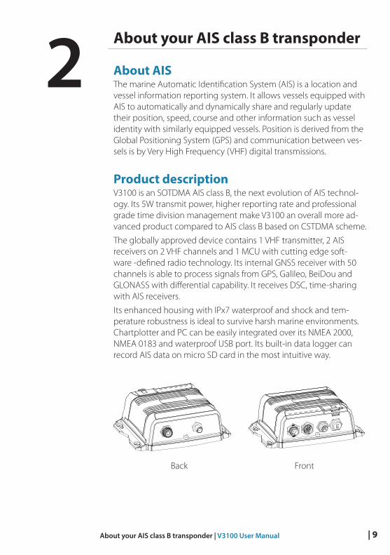
Product descriptionV3100 is an SOTDMA AIS class B, the next evolution of AIS technol-ogy. Its 5W transmit power, higher reporting rate and professional grade time division management make V3100 an overall more ad-vanced product compared to AIS class B based on CSTDMA scheme.
The globally approved device contains 1 VHF transmitter, 2 AIS receivers on 2 VHF channels and 1 MCU with cutting edge soft-ware -defined radio technology. Its internal GNSS receiver with 50 channels is able to process signals from GPS, Galileo, BeiDou and GLONASS with differential capability. It receives DSC, time-sharing with AIS receivers.
Its enhanced housing with IPx7 waterproof and shock and tem-perature robustness is ideal to survive harsh marine environments. Chartplotter and PC can be easily integrated over its NMEA 2000, NMEA 0183 and waterproof USB port. Its built-in data logger can record AIS data on micro SD card in the most intuitive way.
WideLink B600
Back Front
2
10 | About your AIS class B transponder | V3100 User Manual
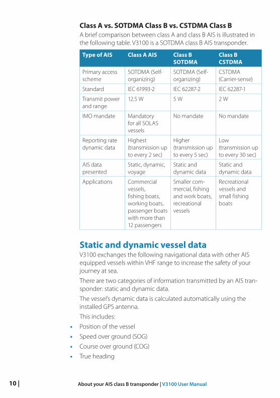
Class A vs. SOTDMA Class B vs. CSTDMA Class B A brief comparison between class A and class B AIS is illustrated in the following table. V3100 is a SOTDMA class B AIS transponder.
Type of AIS Class A AIS Class B SOTDMA
Class B CSTDMA
Primary access scheme
SOTDMA (Self-organizing)
SOTDMA (Self-organizing)
CSTDMA (Carrier-sense)
Standard IEC 61993-2 IEC 62287-2 IEC 62287-1
Transmit power and range
12.5 W 5 W 2 W
IMO mandate Mandatory for all SOLAS vessels
No mandate No mandate
Reporting rate dynamic data
Highest (transmission up to every 2 sec)
Higher (transmission up to every 5 sec)
Low (transmission up to every 30 sec)
AIS data presented
Static, dynamic, voyage
Static and dynamic data
Static and dynamic data
Applications Commercial vessels, fishing boats, working boats, passenger boats with more than 12 passengers
Smaller com-mercial, fishing and work boats, recreational vessels
Recreational vessels and small fishing boats
Static and dynamic vessel dataV3100 exchanges the following navigational data with other AIS equipped vessels within VHF range to increase the safety of your journey at sea.
There are two categories of information transmitted by an AIS tran-sponder: static and dynamic data.
The vessel’s dynamic data is calculated automatically using the installed GPS antenna.
This includes:
• Position of the vessel
• Speed over ground (SOG)
• Course over ground (COG)
• True heading
| 11About your AIS class B transponder | V3100 User Manual
Static data is information about the vessel which must be pro-grammed into the AIS transponder.
This includes:
• Maritime Mobile Service Identity (MMSI)
• Vessel name
• Vessel call sign (if available)
• Vessel type
• Location of GPS antenna on the vessel
The transponder also receives safety-related messages (SRM) from other vessels or persons who are in distress.
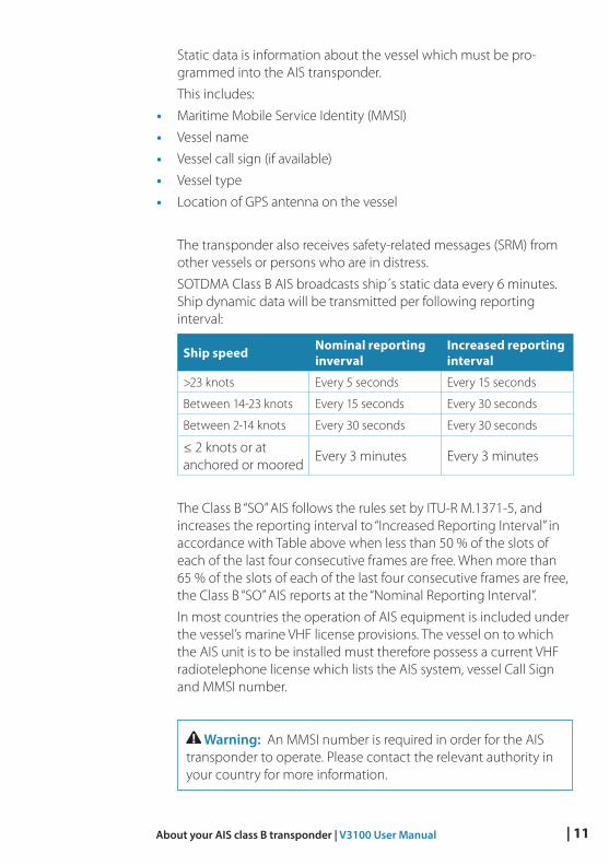
SOTDMA Class B AIS broadcasts ship´s static data every 6 minutes. Ship dynamic data will be transmitted per following reporting interval:
Ship speed Nominal reporting inverval
Increased reporting interval
>23 knots Every 5 seconds Every 15 seconds
Between 14-23 knots Every 15 seconds Every 30 seconds
Between 2-14 knots Every 30 seconds Every 30 seconds
≤ 2 knots or at anchored or moored
Every 3 minutes Every 3 minutes
The Class B “SO” AIS follows the rules set by ITU-R M.1371-5, and increases the reporting interval to “Increased Reporting Interval” in accordance with Table above when less than 50 % of the slots of each of the last four consecutive frames are free. When more than 65 % of the slots of each of the last four consecutive frames are free, the Class B “SO” AIS reports at the “Nominal Reporting Interval”.
In most countries the operation of AIS equipment is included under the vessel’s marine VHF license provisions. The vessel on to which the AIS unit is to be installed must therefore possess a current VHF radiotelephone license which lists the AIS system, vessel Call Sign and MMSI number.
Warning: An MMSI number is required in order for the AIS transponder to operate. Please contact the relevant authority in your country for more information.
12 | About your AIS class B transponder | V3100 User Manual
Important information for US customers There are specific laws in the USA regarding the configuration of AIS class B transponders. If you are a US resident and intend to use your AIS class B transponder in US waters, you should make sure that your retailer has configured your product prior to supplying it to you. If your AIS transponder has not been pre-configured, please contact your dealer for details of how to have it configured.
Warning: In the United States of America, the MMSI and static data must only be entered by a competent installer. The end user of the equipment is not authorized to enter their own vessel data.
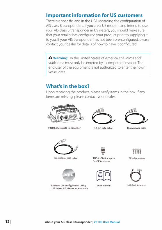
What’s in the box?Upon receiving the product, please verify items in the box. If any items are missing, please contact your dealer.
V3100 AIS Class B Transponder
User manual
12-pin data cable 8-pin power cable
Software CD: configuration utility,USB driver, AIS viewer, user manual
TP3x3/4 screwsTNC-to-SMA adaptorfor GPS antenna
Mini USB to USB cable
GPS-500 Antenna
| 13Installation | V3100 User Manual
Installation
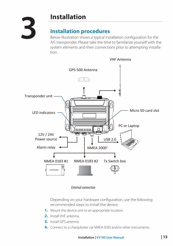
Installation proceduresBelow illustration shows a typical installation configuration for the AIS transponder. Please take the time to familiarize yourself with the system elements and their connections prior to attempting installa-tion.
External connection
Depending on your hardware configuration, use the following recommended steps to install the device:
1. Mount the device unit to an appropriate location.
2. Install VHF antenna.
3. Install GPS antenna.
4. Connect to a chartplotter via NMEA 0183 and/or other instruments.
3
Micro SD card slot
PC or Laptop
USB 2.0
LED indicators
12V / 24VPower source
Alarm relay NMEA 2000 R
NMEA 0183 #2
VHF Antenna
Tx Switch box
GPS-500 Antenna
Chartplotter
NMEA 0183 #1
Transponder unit
14 | Installation | V3100 User Manual
5. Connect to a chartplotter via NMEA 2000 and/or other instruments.
6. Connect to a Tx switch box and/or external alarm system (optional).
7. Connect to an appropriate power source (12V / 24V DC, 2A).
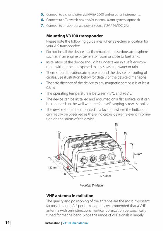
Mounting V3100 transponderPlease note the following guidelines when selecting a location for your AIS transponder:
• Do not install the device in a flammable or hazardous atmosphere such as in an engine or generator room or close to fuel tanks
• Installation of the device should be undertaken in a safe environ-ment without being exposed to any splashing water or rain
• There should be adequate space around the device for routing of cables. See illustration below for details of the device dimensions
• The safe distance of the device to any magnetic compass is at least 0.3 m
• The operating temperature is between -15°C and +55°C
• The device can be installed and mounted on a flat surface, or it can be mounted on the wall with the four self-tapping screws supplied
• The device should be mounted in a location where the indicators can readily be observed as these indicators deliver relevant informa-tion on the status of the device.
Mounting the device
VHF antenna installationThe quality and positioning of the antenna are the most important factors dictating AIS performance. It is recommended that a VHF antenna with omnidirectional vertical polarization be specifically tuned for marine band. Since the range of VHF signals is largely
177.2mm
132mm
60mm
| 15Installation | V3100 User Manual
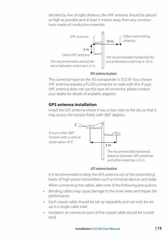
decided by line of sight distance, the VHF antenna should be placed as high as possible and at least 5 meters away from any construc-tions made of conductive materials.
VHF antenna locations
The connector type on the AIS transponder is SO239. Your chosen VHF antenna requires a PL259 connector to mate with this. If your VHF antenna does not use this type of connector, please contact your dealer for details of available adaptors.
GPS antenna installationInstall the GPS antenna where it has a clear view to the sky, so that it may access the horizon freely with 360° degrees.
GPS antenna locations
It is recommended to keep the GPS antenna out of the transmitting beam of high-power transmitters such as Inmarsat devices and radar.
When connecting the cables, take note of the following precautions.
• Bending cables may cause damage to the inner wires and impair the performance
• Each coaxial cable should be set up separately and can only be set up in a single cable tube
• Insulation on connector port of the coaxial cable should be consid-ered.
10 m
2 m
VHF antenna
Other VHF antenna
Other transmitting antenna
The recommended vertical dis-tance between antennas is 2 m.
The recommended horizontal dis-tance between antennas is 10 m.
5˚
3 m
The recommended horizontal distance between GPS antennas and other antennas is 3 m.
Ensure a free 360° horizon with a vertical observation of 5°.
16 | Installation | V3100 User Manual
V3100 is tested and certified with the GPS-500 antenna. It’s recom-mended to use GPS-500 to ensure optimal reliability of your AIS system.
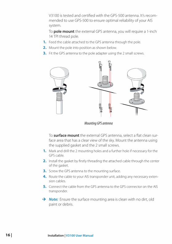
To pole mount the external GPS antenna, you will require a 1-inch 14 TPI thread pole.
1. Feed the cable attached to the GPS antenna through the pole.
2. Mount the pole into position as shown below.
3. Fit the GPS antenna to the pole adapter using the 2 small screws.
Mounting GPS antenna
To surface mount the external GPS antenna, select a flat clean sur-face area that has a clear view of the sky. Mount the antenna using the supplied gasket and the 2 small screws.
1. Mark and drill the 2 mounting holes and a further hole if necessary for the GPS cable.
2. Install the gasket by firstly threading the attached cable through the center of the gasket.
3. Screw the GPS antenna to the mounting surface.
4. Route the cable to your AIS transponder unit, adding any necessary exten-sion cables.
5. Connect the cable from the GPS antenna to the GPS connector on the AIS transponder.
¼ Note: Ensure the surface mounting area is clean with no dirt, old paint or debris.
| 17Installation | V3100 User Manual
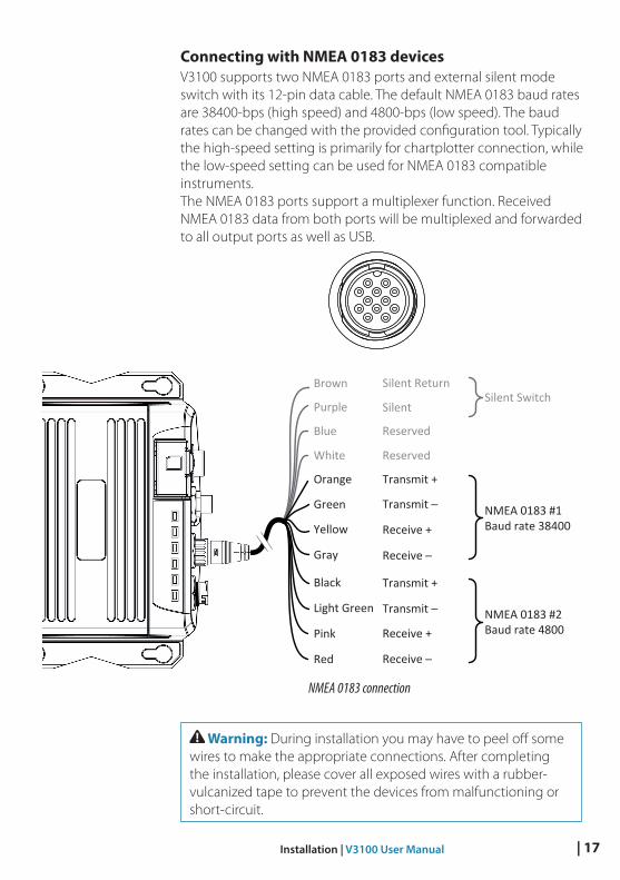
Connecting with NMEA 0183 devicesV3100 supports two NMEA 0183 ports and external silent mode switch with its 12-pin data cable. The default NMEA 0183 baud rates are 38400-bps (high speed) and 4800-bps (low speed). The baud rates can be changed with the provided configuration tool. Typically the high-speed setting is primarily for chartplotter connection, while the low-speed setting can be used for NMEA 0183 compatible instruments. The NMEA 0183 ports support a multiplexer function. Received NMEA 0183 data from both ports will be multiplexed and forwarded to all output ports as well as USB.12pin 8pin
NMEA 0183 connection
Warning: During installation you may have to peel off some wires to make the appropriate connections. After completing the installation, please cover all exposed wires with a rubber-vulcanized tape to prevent the devices from malfunctioning or short-circuit.
Transmit +
Transmit ─
Receive +
Receive ─
Silent
Silent Return
White
Blue
Orange
Green
Brown
PurpleSilent Switch
NMEA 0183 #1Baud rate 38400
Transmit +
Transmit ─
Receive +
Receive ─
Gray
Yellow
Black
NMEA 0183 #2Baud rate 4800Pink
Red
Light Green
Reserved
Reserved
18 | Installation | V3100 User Manual
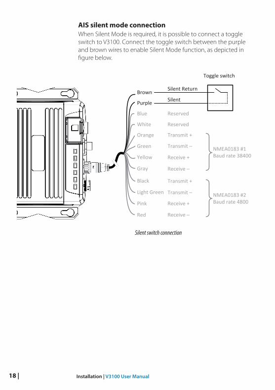
AIS silent mode connectionWhen Silent Mode is required, it is possible to connect a toggle switch to V3100. Connect the toggle switch between the purple and brown wires to enable Silent Mode function, as depicted in figure below.
Silent switch connection
Transmit +
Transmit ─
Receive +
Receive ─
Silent
Silent Return
White
Blue
Orange
Green
Brown
Purple
NMEA0183 #1Baud rate 38400
Transmit +
Transmit ─
Receive +
Receive ─
Gray
Yellow
Black
NMEA0183 #2Baud rate 4800Pink
Red
Light Green
Reserved
Reserved
Toggle switch
| 19Installation | V3100 User Manual
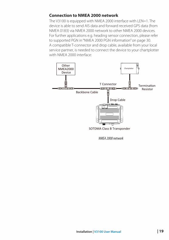
Connection to NMEA 2000 networkThe V3100 is equipped with NMEA 2000 interface with LEN=1. The device is able to send AIS data and forward received GPS data (from NMEA 0183) via NMEA 2000 network to other NMEA 2000 devices. For further applications e.g. heading sensor connection, please refer to supported PGN in “NMEA 2000 PGN information” on page 30. A compatible T-connector and drop cable, available from your local service partner, is needed to connect the device to your chartplotter with NMEA 2000 interface:
NMEA 2000 network
Other NMEA2000
Device
T Connector
Backbone Cable
Drop Cable
Termination Resistor
SOTDMA Class B Transponder
Chartplotter
20 | Installation | V3100 User Manual
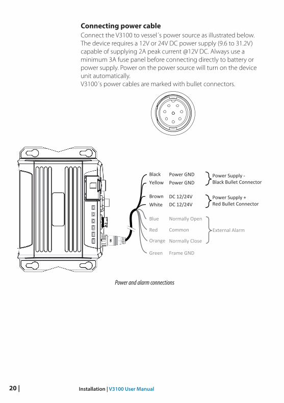
Connecting power cableConnect the V3100 to vessel´s power source as illustrated below. The device requires a 12V or 24V DC power supply (9.6 to 31.2V) capable of supplying 2A peak current @12V DC. Always use a minimum 3A fuse panel before connecting directly to battery or power supply. Power on the power source will turn on the device unit automatically. V3100´s power cables are marked with bullet connectors.12pin 8pin
Power and alarm connections
Common
Power GND
Normally Open
Normally Close
Power GND
DC 12/24V WhiteBrown
Blue
Red
BlackYellow
Power Supply -Black Bullet Connector
Green
Orange
External Alarm
DC 12/24V
Frame GND
Power Supply +Red Bullet Connector
| 21Configuring your AIS transponder | V3100 User Manual
Configuring your AIS transponderYour V3100 is delivered with the Navico AIS System Configurator tool, which allows the user to set up the transponder and make real-time diagnosis of any issues. A more detailed user guide of the configuration tool can be found in the “Help” of the software.
Connecting to your AIS transponder
Required itemsBefore proceeding the configuration procedure, make sure the fol-lowing items are available:
• USB Driver (included in the software CD)
• USB cable (included in the box)
• Mac OS X 10.6 and later or Microsoft® Windows® XP, Windows® Vista®, Windows 7, Windows 8, Windows 10 (including both 32 and 64-bit versions)
• One available USB port on PC
• Available CD-ROM drive on PC.
¼ Note: For configuration and firmware upgrade purpose, the V3100 can be powered only by USB. When USB power is in use, the device will not transmit any data.
Installing Navico AIS System Configurator toolThe System Configurator tool must be installed before connecting your transponder to your PC or Mac.
The application can be found on the CD supplied with your AIS Class B transponder. Insert the CD into your PC or Mac and navigate to the ‘Windows’ or ‘Finder’ folder:
Windows: Double-click the ‘setup.exe’ item to start the installer and follow the on-screen instructions.
Mac: Double-click the ‘AISConfigurator.dmg’ file. A new Finder win-dow will open, drag the Navico AIS Configurator tool to the Applica-tions folder to complete the installation process.
¼ Note: You can now launch the application from the Windows® Start menu or the Mac Applications folder.
4
22 | Configuring your AIS transponder | V3100 User Manual
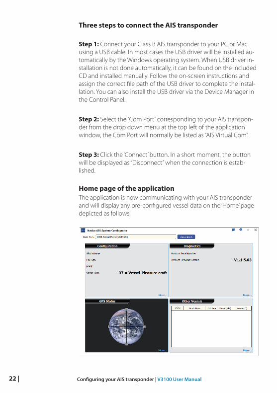
Three steps to connect the AIS transponder
Step 1: Connect your Class B AIS transponder to your PC or Mac using a USB cable. In most cases the USB driver will be installed au-tomatically by the Windows operating system. When USB driver in-stallation is not done automatically, it can be found on the included CD and installed manually. Follow the on-screen instructions and assign the correct file path of the USB driver to complete the instal-lation. You can also install the USB driver via the Device Manager in the Control Panel.
Step 2: Select the “Com Port” corresponding to your AIS transpon-der from the drop down menu at the top left of the application window, the Com Port will normally be listed as “AIS Virtual Com”.
Step 3: Click the ‘Connect’ button. In a short moment, the button will be displayed as “Disconnect” when the connection is estab-lished.
Home page of the applicationThe application is now communicating with your AIS transponder and will display any pre-configured vessel data on the ‘Home’ page depicted as follows.
| 23Configuring your AIS transponder | V3100 User Manual
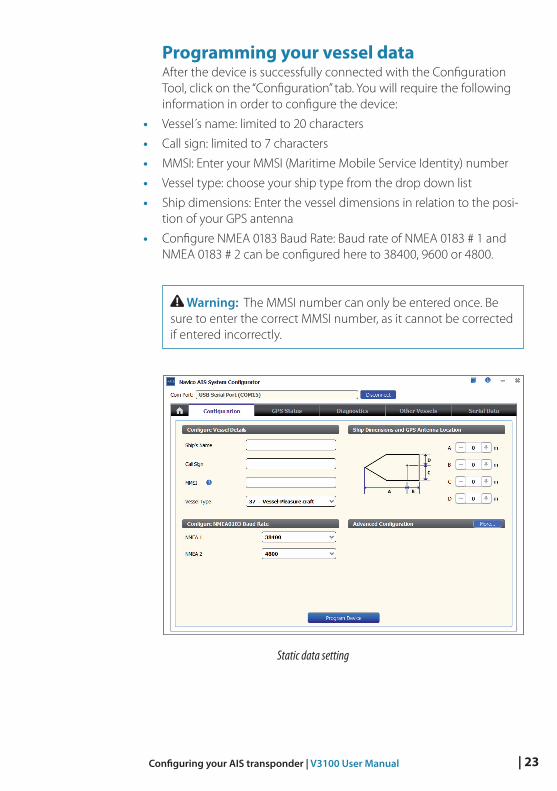
Programming your vessel dataAfter the device is successfully connected with the Configuration Tool, click on the “Configuration” tab. You will require the following information in order to configure the device:
• Vessel s name: limited to 20 characters
• Call sign: limited to 7 characters
• MMSI: Enter your MMSI (Maritime Mobile Service Identity) number
• Vessel type: choose your ship type from the drop down list
• Ship dimensions: Enter the vessel dimensions in relation to the posi-tion of your GPS antenna
• Configure NMEA 0183 Baud Rate: Baud rate of NMEA 0183 # 1 and NMEA 0183 # 2 can be configured here to 38400, 9600 or 4800.
Warning: The MMSI number can only be entered once. Be sure to enter the correct MMSI number, as it cannot be corrected if entered incorrectly.
Static data setting
24 | Get started | V3100 User Manual
Get startedThe device starts up whenever the connected power source is ON. It will operate automatically when the device has been properly configured and GPS/VHF antennas are properly installed. The device transmits its own ship positions depending on vessel´s moving speed and should receive information of other vessels in the vicinity. The operation status of the device can be observed with the LED lights on the unit. Description of the LED indications is provided in the following section.
LED indicatorsIndicator Light Description
Power Green, steady
The device has been powered up correctly. By USB power, the Power LED does not light, showing that the device is in low power mode.
Tx/Silent Green, flashing
The device is transmitting AIS data. The flashing interval varies depending on vessel speed.
Orange, steady
The device is in silent mode, no AIS transmis-sion at all.
Rx Green, flashing
The device is receiving AIS data.
SD Green, flashing
SD card is being accessed.
Green, steady
SD card is inaccessible due to malfunction.
Error Red, steady
MMSI is not properly programmed.
Red, flashing
A BIIT system error is detected, referring to chapter “Built-in integrity test (BIIT) page 25, or by USB power.
5
| 25Get started | V3100 User Manual
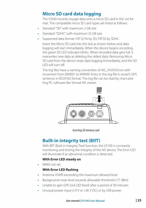
Micro SD card data loggingThe V3100 records voyage data onto a micro SD card in the .txt for-mat. The compatible micro SD card types are listed as follows:
• Standard “SD” with maximum 2 GB size
• Standard “SDHC” with maximum 32 GB size
• Supported data format: FAT12/16 by SD, FAT32 by SDHC.
Insert the Micro SD card into the slot as shown below and data logging will start immediately. When the device begins recording, the green SD LED indicator blinks. When recorded data gets full, it overwrites new data as deleting the oldest data. Removing Micro SD card from the device stops data logging immediately, and the SD LED will turn off.
The log files have a naming convention of AIS_XXXXXX.txt with increment from 000001 to 999999. Entry in the log file is vessel’s GPS sentence in IEC61162 format. The log file can be read by chart plot-ting PC software like Simrad AIS viewer.
WideLink B600 Figure 11 Inserting SD Memory Card
Inserting SD memory card
Built-in integrity test (BIIT)With BIIT (Built in Integrity Test) function, the V3100 is constantly monitoring and testing the integrity of the AIS device. The Error LED will illuminate if an abnormal condition is detected.
With Error LED steady on• MMSI not set.
With Error LED flashing• Antenna VSWR exceeding the maximum allowed level
• Background noise level exceeds allowable threshold (-77 dBm)
• Unable to gain GPS lock (3D fixed) after a period of 30 minutes
• Unusual power input (<9 V or >36 V DC) or by USB power.
26 | Specifications | V3100 User Manual
Specifications
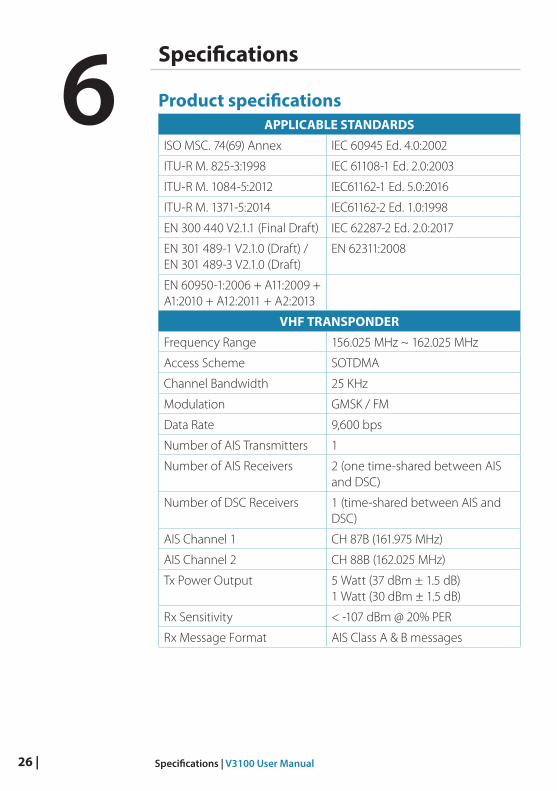
Product specificationsAPPLICABLE STANDARDS
ISO MSC. 74(69) Annex IEC 60945 Ed. 4.0:2002
ITU-R M. 825-3:1998 IEC 61108-1 Ed. 2.0:2003
ITU-R M. 1084-5:2012 IEC61162-1 Ed. 5.0:2016
ITU-R M. 1371-5:2014 IEC61162-2 Ed. 1.0:1998
EN 300 440 V2.1.1 (Final Draft) IEC 62287-2 Ed. 2.0:2017
EN 301 489-1 V2.1.0 (Draft) / EN 301 489-3 V2.1.0 (Draft)
EN 62311:2008
EN 60950-1:2006 + A11:2009 + A1:2010 + A12:2011 + A2:2013
VHF TRANSPONDER
Frequency Range 156.025 MHz ~ 162.025 MHz
Access Scheme SOTDMA
Channel Bandwidth 25 KHz
Modulation GMSK / FM
Data Rate 9,600 bps
Number of AIS Transmitters 1
Number of AIS Receivers 2 (one time-shared between AIS and DSC)
Number of DSC Receivers 1 (time-shared between AIS and DSC)
AIS Channel 1 CH 87B (161.975 MHz)
AIS Channel 2 CH 88B (162.025 MHz)
Tx Power Output 5 Watt (37 dBm ± 1.5 dB) 1 Watt (30 dBm ± 1.5 dB)
Rx Sensitivity < -107 dBm @ 20% PER
Rx Message Format AIS Class A & B messages
6
| 27Specifications | V3100 User Manual
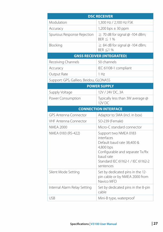
DSC RECEIVER
Modulation 1,300 Hz / 2,100 Hz FSK
Accuracy 1,200 bps ± 30 ppm
Spurious Response Rejection ≧ 70 dB for signal @ -104 dBm; BER ≦ 1 %
Blocking ≧ 84 dB for signal @ -104 dBm; BER ≦1 %
GNSS RECEIVER (INTEGRATED)
Receiving Channels 50 channels
Accuracy IEC 61108-1 compliant
Output Rate 1 Hz
Support: GPS, Gallieo, Beidou, GLONASS
POWER SUPPLY
Supply Voltage 12V / 24V DC, 3A
Power Consumption Typically less than 3W average @ 12V DC
CONNECTION INTERFACE
GPS Antenna Connector Adaptor to SMA (incl. in box)
VHF Antenna Connector SO-239 (Female)
NMEA 2000 Micro-C standard connector
NMEA 0183 (RS-422) Support two NMEA 0183 interfaces Default baud rate 38,400 & 4,800 bps Configurable and separate Tx/Rx baud rate Standard IEC 61162-1 / IEC 61162-2 sentences
Silent Mode Setting Set by dedicated pins in the 12-pin cable or by NMEA 2000 from Navico MFD
Internal Alarm Relay Setting Set by dedicated pins in the 8-pin cable
USB Mini-B type, waterproof
28 | Specifications | V3100 User Manual
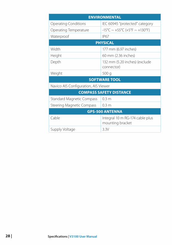
ENVIRONMENTAL
Operating Conditions IEC 60945 “protected” category
Operating Temperature -15°C ~ +55°C (+5°F ~ +130°F)
Waterproof IP67
PHYSICAL
Width 177 mm (6.97 inches)
Height 60 mm (2.36 inches)
Depth 132 mm (5.20 inches) (exclude connector)
Weight 500 g
SOFTWARE TOOL
Navico AIS Configuration, AIS Viewer
COMPASS SAFETY DISTANCE
Standard Magnetic Compass 0.3 m
Steering Magnetic Compass 0.3 m
GPS-500 ANTENNA
Cable Integral 10 m RG-174 cable plus mounting bracket
Supply Voltage 3.3V
| 29Specifications | V3100 User Manual
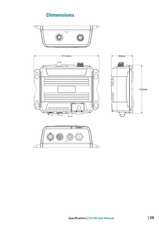
Dimensions
177.2mm 60mm
132mm
WideLink B600 Dimension
30 | Specifications | V3100 User Manual
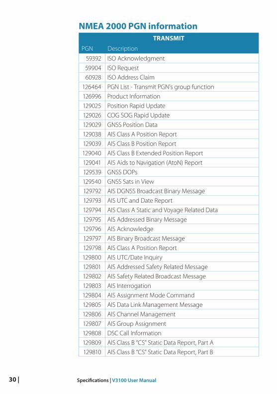
NMEA 2000 PGN informationTRANSMIT
PGN Description
59392 ISO Acknowledgment
59904 ISO Request
60928 ISO Address Claim
126464 PGN List - Transmit PGN's group function
126996 Product Information
129025 Position Rapid Update
129026 COG SOG Rapid Update
129029 GNSS Position Data
129038 AIS Class A Position Report
129039 AIS Class B Position Report
129040 AIS Class B Extended Position Report
129041 AIS Aids to Navigation (AtoN) Report
129539 GNSS DOPs
129540 GNSS Sats in View
129792 AIS DGNSS Broadcast Binary Message
129793 AIS UTC and Date Report
129794 AIS Class A Static and Voyage Related Data
129795 AIS Addressed Binary Message
129796 AIS Acknowledge
129797 AIS Binary Broadcast Message
129798 AIS Class A Position Report
129800 AIS UTC/Date Inquiry
129801 AIS Addressed Safety Related Message
129802 AIS Safety Related Broadcast Message
129803 AIS Interrogation
129804 AIS Assignment Mode Command
129805 AIS Data Link Management Message
129806 AIS Channel Management
129807 AIS Group Assignment
129808 DSC Call Information
129809 AIS Class B “CS” Static Data Report, Part A
129810 AIS Class B “CS” Static Data Report, Part B
| 31Specifications | V3100 User Manual
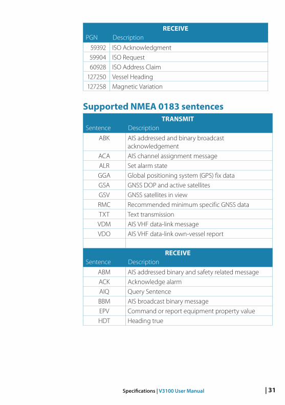
RECEIVEPGN Description
59392 ISO Acknowledgment
59904 ISO Request
60928 ISO Address Claim
127250 Vessel Heading
127258 Magnetic Variation
Supported NMEA 0183 sentencesTRANSMIT
Sentence Description
ABK AIS addressed and binary broadcast acknowledgement
ACA AIS channel assignment message
ALR Set alarm state
GGA Global positioning system (GPS) fix data
GSA GNSS DOP and active satellites
GSV GNSS satellites in view
RMC Recommended minimum specific GNSS data
TXT Text transmission
VDM AIS VHF data-link message
VDO AIS VHF data-link own-vessel report
RECEIVESentence Description
ABM AIS addressed binary and safety related message
ACK Acknowledge alarm
AIQ Query Sentence
BBM AIS broadcast binary message
EPV Command or report equipment property value
HDT Heading true
32 | Troubleshooting | V3100 User Manual
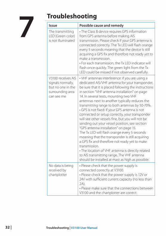
TroubleshootingIssue Possible cause and remedy
The transmitting LED (Green color) is not illuminated
• The Class B device requires GPS information from GPS antenna before making AIS transmission. Please check if your GPS antenna is connected correctly. The Tx LED will flash orange every 5 seconds meaning that the device is still acquiring a GPS fix and therefore not ready yet to make a transmission. • For each transmission, the Tx LED indicator will flash once quickly. The green light from the Tx LED could be missed if not observed carefully.
V3100 receives AIS signals normally, but no one in the surrounding area can see me
• VHF antennas interference: if you are using a dedicated AIS/VHF antenna for your transponder, be sure that it is placed following the instructions in section “VHF antenna installation” on page 14. In several tests, mounting two VHF antennas next to another typically reduces the transmitting range to both antennas by 50-70%. • GPS is not fixed: If your GPS antenna is not connected or setup correctly, your transponder will see other vessels fine, but you will not be sending out your vessel position, see section “GPS antenna installation” on page 15. The Tx LED will flash orange every 5 seconds meaning that the transponder is still acquiring a GPS fix and therefore not ready yet to make transmission. • The location of VHF antenna is directly related to AIS transmitting range. The VHF antenna should be installed at mast as high as possible.
No data is being received by chartplotter
• Please check that the power supply is connected correctly at V3100. • Please check that the power supply is 12V or 24V with sufficient current capacity (no less than 2A). • Please make sure that the connections between V3100 and the chartplotter are correct.
7
| 33Troubleshooting | V3100 User Manual
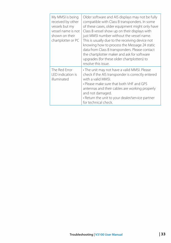
My MMSI is being received by other vessels but my vessel name is not shown on their chartplotter or PC
Older software and AIS displays may not be fully compatible with Class B transponders. In some of these cases, older equipment might only have Class B vessel show up on their displays with just MMSI number without the vessel name. This is usually due to the receiving device not knowing how to process the Message 24 static data from Class B transponders. Please contact the chartplotter maker and ask for software upgrades (for these older chartplotters) to resolve this issue.
The Red Error LED indication is illuminated
• The unit may not have a valid MMSI. Please check if the AIS transponder is correctly entered with a valid MMSI. • Please make sure that both VHF and GPS antennas and their cables are working properly and not damaged. • Return the unit to your dealer/service partner for technical check.
34 | Abbreviations | V3100 User Manual
Abbreviations
AIS Automatic Identification System
COG Course Over Ground
CPA Distance to Closest Point of Approach
CSTDMA Carrier-Sense Time Division Multiple Access
SOTDMA Self-Organized Time Division Multiple Access
DSC Digital Selective Calling
ECS Electronic Chart System
ETA Estimated Time of Arrival
GPS Global Positioning System
IMO International Maritime Organization
MMSI Maritime Mobile Service Identity
SOG Speed Over Ground
TCPA Time to Closest Point of Approach
TDMA Time Division Multiple Access
UTC Coordinated Universal Time
VHF Very High Frequency
VTS Vessel Traffic Services
8
| 35How to determine Serial Port | V3100 User Manual
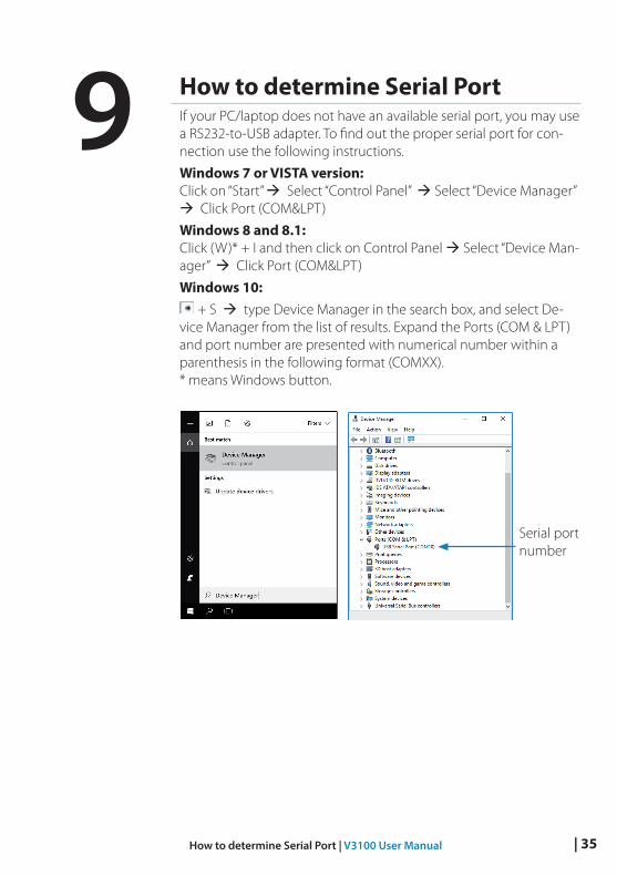
How to determine Serial PortIf your PC/laptop does not have an available serial port, you may use a RS232-to-USB adapter. To find out the proper serial port for con-nection use the following instructions.
Windows 7 or VISTA version: Click on “Start” Select “Control Panel” Select “Device Manager” Click Port (COM&LPT)
Windows 8 and 8.1: Click (W)* + I and then click on Control Panel Select “Device Man-ager” Click Port (COM&LPT)
Windows 10: + S type Device Manager in the search box, and select De-
vice Manager from the list of results. Expand the Ports (COM & LPT) and port number are presented with numerical number within a parenthesis in the following format (COMXX). * means Windows button.
Serial port number
9


*988-12032-0
02*


