Revision and Errata List May 1, 2003 (Second Printing) December 1, 2002 (First Printing) AISC Design Guide 14: Staggered Truss Framing Systems The editorial corrections dated May 1, 2003 have been made in the Second Printing, December 2002. Those editorial corrections dated December 1, 2002 apply to the First Printing, December 2001. To facilitate the incorporation of these corrections, this booklet has been constructed using copies of the revised pages, with corrections noted. The user may find it convenient in some cases to hand-write a correction; in others, a cut-and-paste approach may be more efficient.
Transcript
Revision and Errata List May 1, 2003 (Second Printing)
December 1, 2002 (First Printing)
AISC Design Guide 14: Staggered Truss Framing Systems
The editorial corrections dated May 1, 2003 have been made in the Second Printing, December 2002. Those editorial corrections dated December 1, 2002 apply to the FirstPrinting, December 2001. To facilitate the incorporation of these corrections, this booklet has been constructed using copies of the revised pages, with corrections noted. The user may find it convenient in some cases to hand-write a correction; in others, a cut-and-paste approach may be more efficient.
Table 2.1 Torsional Rigidity, Even Floors
TrussT1BT1D
T1F
Table 2.2 Torsional Rigidity, Odd Floors
TrussT2CT2E
T2G
Table 2.3 Shear Force in Each Truss due to Lateral Loads (Bottom Floor)
T1B
T1D
T1F
T2C
T2E
T2G
-76
-4
80
-80
4
76
383
383
383
383
383
383
-238
-13
251
251
-13
-238
145
370
634*
634*
370
145
-48
-3
51
51
-3
-48
335*
380*
434
434
380*
335*
335
380
634
634
380
335
1.00
1.13
1.89
1.89
1.13
1.00
2.4 Diaphragm Chords
The perimeter steel beams are used as diaphragm chords.The chord forces are calculated approximately as follows:
H = M/D (2-7)
where
H = chord tension or compression forceM = moment applied to the diaphragmD = depth of the diaphragm
The plank to spandrel beam connection must be adequateto transfer this force from the location of zero moment tothe location of maximum moment. Thus observing themoment diagrams in Fig. 2.4, the following chord forcesand shear flows needed for the plank-to-spandrel connec-tion design are calculated:
With +5% additional eccentricity:
where constant 0.75 is applied for wind or seismic loads.The calculated shear flows, are shown in Fig. 2.4(a).For -5% additional eccentricity, similar calculations areconducted and the results are shown in Fig. 2.4(b). Theshear flows of the two cases are combined in Fig. 2.4(c),
10
Truss
Fig. 2.3 Diaphragm acting as a deep beam.
Rev.12/1/02
Rev.12/1/02
5,776
fH
where a value with * indicates the larger shear flow thatgoverns. These shear forces and shear flows due to serviceloads on the bottom floor are then multiplied by the heightadjustment factors for story shear to obtain the final designof the diaphragms up to the height of the building as shownin the table in Fig. 2.5. The table is drawn on the structuraldrawings and is included as part of the construction contractdocuments. Forces given on structural drawings are gener-ally computed from service loads. In case factored forcesare to be given on structural drawings, they must be clearlyspecified.
The perimeter steel beams must be designed to supportthe gravity loads in addition to the chord axial forces, H.
The connections of the beams to the columns must developthese forces (H). The plank connections to the spandrelbeams must be adequate to transfer the shear flow, Theplank connections to the spandrel are usually made by shearplates embedded in the plank and welded to the beams (Fig.1.2 and Fig. 2.6). Where required, the strength of plankembedded connections is proven by tests, usually availablefrom the plank manufacturers. All forces must be shown onthe design drawings. The final design of the diaphragm isshown in Fig. 2.5.
11
Rev.12/1/02f H
3.6 Vertical and Diagonal Members b. Wind
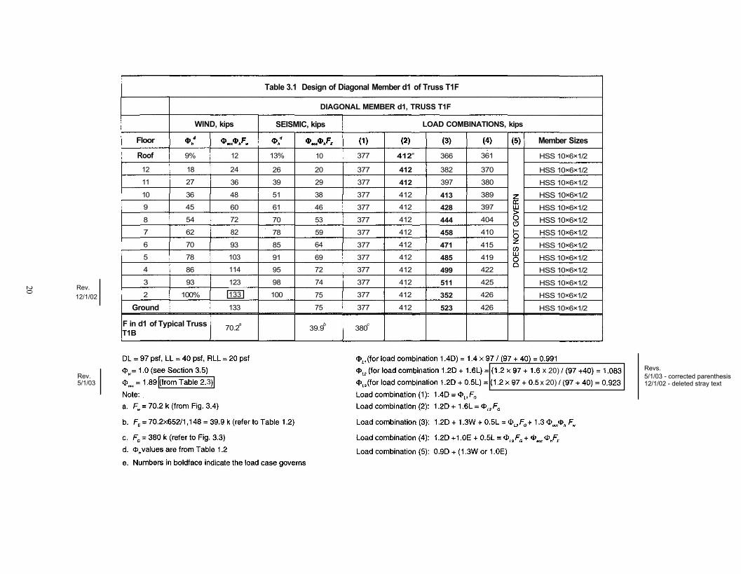
The detailed calculations for the design of diagonal memberd l in truss T1F of each floor using load coefficients areshown in Table 3.1, where load coefficients and
are applied to different load combinations. Truss T1Frather than typical truss T1B is intentionally selected as anexample here for explanation of how the load coefficientsare applied. Five load combinations as specified in ASCE7 are considered in this table. A 50% live load reduction isused in the design of the diagonal members. Numbers inboldface in the table indicate the load case that governs.The governing tensile axial forces of the diagonal membersrange from 412 k to 523 k for different floors. HSS 10x6x½ is selected per AISC requirements for all the diagonalmembers.
3.7 Truss Chords
The designer must investigate carefully all load cases so asto determine which load case governs. For this designexample for truss chords, it is found that the load combina-tion of 1.2D + 1.6W + 0.5L governs. The steel design mustcomply with AISC Equation H1-1a.
Calculations for gravity and wind loads are made sepa-rately and then combined.
a. Gravity
It is assumed that the chords are loaded with a uniformlydistributed load. Using a 50% live load reduction, the fol-lowing are calculated for the chords of truss T1F on the sec-ond story:
It is observed that while wind loads vary with buildingheights, gravity loads do not. Thus, Table 3.2 is created andthe chord moments are calculated using coefficient ofeach story as shown. The designed wide-flange sections perAISC Equation H1-1a are also shown in the table. To facil-itate the design calculations, the axial force and bendingmoment strengths of possible W10 members are calculatedfirst and listed in Table 3.3.
3.8 Computer Modeling
When designing staggered truss buildings using computermodels (stiffness matrix solutions), the results vary with theassumptions made regarding the degree of composite actionbetween the trusses and the concrete floor. The designresults are particularly sensitive to modeling because a baretruss is more flexible than a truss modeled with a concretefloor. Upon grouting, the truss chords become compositewith the concrete floor and thus the floor shares with thetruss chords in load bearing. Yet, a concrete floor, particu-larly a concrete plank floor, may not effectively transmittensile stresses. Also, there is limited information on plankand steel composite behavior. In addition, lateral loads areassumed to be distributed to the trusses by the concretefloor diaphragm and the participation of the truss chords indistributing these forces may be difficult to quantify.
A reasonable approach to this problem is the assumptionthat the diaphragm is present when solving for lateral loads,but is ignored when solving for gravity loads. This requiresworking with two computer models—one for gravity loads
19
The maximum wind moment in the chords occurs in theVierendeel panel.
The axial force applied to the chord due to the wind loadcan be neglected as will be explained in Section 3.8. Theabove moment is also applied to the adjacent span, whichhas a span length of 9.5 ft same as the span length used forthe gravity load moment calculation. The member forces ofthe chords on the second story due to gravity and windloads are then combined as follows:
Rev.5/1/03
Rev.12/1/02x
fH
WIND, kips
Table 3.1 Design of Diagonal Member d1 of Truss T1F
DIAGONAL MEMBER d1, TRUSS T1F
SEISMIC, kips LOAD COMBINATIONS, kips
Roof12
11
10
9
8
7
6
5
4
3
2
Ground
9%
18
27
36
45
54
62
70
78
86
93
100%
F in d1 of Typical TrussT1B
12
24
36
48
60
72
82
93
103
114
123
1
133
70.2 a
13%
26
39
51
61
70
78
85
91
95
98
100
10
20
29
38
46
53
59
64
69
72
74
75
75
39.9 b
377
377
377
377
377
377
377
377
377
377
377
377
377
380 c
412 e
412
412412
412
412
412
412
412
412
412
412
412
366
382
397
413428
444
458
471
485
499
511
352
523
361
370
380
389
397
404
410
415
419
422
425
426
426
Member Sizes
HSS 10×6×1/2
HSS 10×6×1/2
HSS 10×6×1/2
HSS 10×6×1/2HSS 10×6×1/2
HSS 10×6×1/2HSS 10×6×1/2HSS 10×6×1/2
HSS 10×6×1/2
HSS 10×6×1/2
HSS 10×6×1/2
HSS 10×6×1/2
HSS 10×6×1/2
Floor
20
Rev.5/1/03
Revs.5/1/03 - corrected parenthesis
Rev.12/1/02
12/1/02 - deleted stray text
133
3xx20)20)
Chapter 7FIRE PROTECTION OF STAGGERED TRUSSESFire safety is a fundamental requirement of building designand construction and fire resistance is one of the most vitalelements of all components of a structure.
Qualifying criteria to meet these requirements areincluded in various building codes of national stature.These are used as standards in different areas of the countryand which may or may not be further regulated by the localauthorities having jurisdiction. The codes (and publishingorganization) are:
- Standard Building Code (SBCCI)- Uniform Building Code (ICBO)- National Building Code (BOCA)
These code regulations are based on performanceachieved through the standard ASTM E119 test (AlternativeTest of Protection for Structural Steel Columns). Due to thedimensional constraints imposed by the fire testing cham-bers, specific fire tests for steel trusses that simulate actualconditions have not been performed. Therefore, individualtruss members are regarded as columns for the purpose ofrating their fire resistance and the applicable code require-ment will be applied for each member.
By definition, a staggered truss spans from floor slab tofloor slab. Slabs are typically pre-cast concrete and have afire resistance rating. The truss and columns are other ele-ments of this assembly requiring fire protection. There arebasically two methods of providing fire protection for steeltrusses in this type of assembly:
- Encapsulating it, in its entirety, with a fire-rated enclo-sure.
- Providing fire protection to each truss member.
In the former, enclosure can be any type of fire-ratedassembly. Local regulation, however, might reference dif-
ferent testing laboratories as accepted standards for a par-ticular fire rating.
For economy in materials and construction time, gypsumboard and metal stud walls are preferred. Gypsum boardtype "X" and light-gage metal studs in any of the approvedconfigurations for a particular rating is acceptable. How-ever, removals of portions of the wall, renovations or addi-tions with non-rated assemblies are issues that need to beconsidered to avoid possible future violations of fire ratingintegrity when choosing this method.
The other option is to protect each truss member with oneof the following methods:
• If the truss is to be enclosed and/or protected againstdamage and without regard to aesthetics, gypsum-based, cementitious spray-applied fireproofing isoften the most economical option.
• Intumescent paint films can be used where aestheticsare of prime concern, and visual exposure of the steeltruss design is desired. In addition this product is suit-able for interior and exterior applications. Neverthe-less, this method is often one of the most expensive atthe present time.
• For exterior applications and for areas exposed to traf-fic, abrasion and impact, a medium- or high-densitycement-based formulation is suitable and can betrowel-finished for improved aesthetics.
Whatever method is chosen, the designer must work inclose consultation with the product manufacturer by sharingthe specifics of the project and relating the incoming tech-nical information to the final design. Final approval must beobtained from the local authorities having jurisdiction overthese regulations.