AIVSE 670 Access Interface Analog-Video Standard Einbau Produktinformation Access Interface Analog- Video Standard Einbau Product information Access analogue video standard interface mounting Information produit Access Interface vidéo ana- logique standard, montage Opuscolo informativo sul prodotto Montaggio dell’interfaccia video analogica standard Access Productinformatie Access interface analoog video standaard inbouw Produktinformation Access interface analog video standard indbygning Produktinformation Access gränssnitt analog- video Standard montering Información de producto Access gränssnitt analog- video Standard montering Informacja o produkcie Montaż interfejsu Access Interface Analog-Video Standard Информация о продуктах Интерфейс Access ана- логовый видео стандарт монтаж AIVSE 670-0
Transcript
AIVSE 670
Access Interface Analog-Video StandardEinbau
ProduktinformationAccess Interface Analog-Video Standard Einbau
Product informationAccess analogue video standard interface mounting
Information produitAccess Interface vidéo ana-logique standard, montage
Opuscolo informativo sul prodottoMontaggio dell’interfaccia video analogica standard Access
ProductinformatieAccess interface analoog video standaard inbouw
ProduktinformationAccess interface analog video standard indbygning
ProduktinformationAccess gränssnitt analog-video Standard montering
Información de productoAccess gränssnitt analog-video Standard montering
Informacja o produkcieMontaż interfejsu Access Interface Analog-Video Standard
Информация о продуктахИнтерфейс Access ана-логовый видео стандарт монтаж
AIVSE 670-0
2
1
a b
S5 * Versorgung 12/24 V DC max. 200 mA, permanent
S6 * Versorgung 12/24 V DC max. 200 mA, Steuersignal abhängig
S7 Gemeinsamer Bezugspunkt für S5, S6
L/S Koaxanschluss L = Leiter, S = Schirm
* Der Gesamtstrom von S5 - S7 und S6 - S7 ist auf 200 mA begrenzt. Die Ausgangsspannung entspricht immer der eingestellten Schalter–stellung.
Deutsch
AnwendungAccess Interface Analog-Video Standard, in flacher Bauform, zur Anbindung der eingebauten Kamera an den ATLC 670-...Nach erfolgtem Türruf erscheint das Bild der eingebauten Kamera automatisch auf der Access-Innensprechstelle, eine manuelle Anwahl der Tür ist ebenfalls möglich. Die Kamera ist nicht steuerbar.
Elektrische Spannung
Einbau, Montage und Service-arbeiten elektrischer Geräte dürfen ausschließlich durch eine Elektro-Fachkraft erfolgen.
Elektrostatische Aufladung
Durch elektrostatische Aufladung kann bei direktem Kontakt mit der Leiterplatte das Gerät zerstört werden. Vermeiden Sie daher ein direktes Berühren der Leiterplatte.
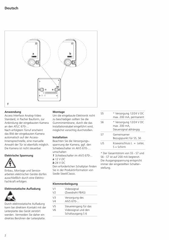
MontageUm die eingebaute Elektronik nicht zu beschädigen sollten Sie die Gummimembrane, durch die das Installationskabel eingeführt wird, möglichst vorsichtig durchstoßen.
InstallationBeachten Sie die Versorgungs–spannung der Kamera, ggf. den Schiebeschalter im AIVS 670-… umschalten1 Schiebeschalter im AIVS 670-...a 12 V DCb 24 V DCDen erforderlichen Schaltplan finden Sie in der Produktinformation von Siedle Steel/Classic.
Klemmenbelegung
V1 V2
Videosignal (Zweidraht FBAS)
V3 V4
Versorgung des AIVS 670-...
V5 V6
Steuereingang für das Videosignal und den Schaltausgang S 6
3
ApplicationAccess analogue video standard interface in surface-mount housing for connection to the integrated camera at the ATLC 670-...Following a door call, the picture from the analogue camera automati-cally appears on the Access indoor call station. Manual selection of the door is also possible. The camera cannot be controlled.
Electrical voltage
Mounting, installation and servicing work on electrical devices may only be performed by a suitably qualified electrician.
Electrostatic charging
As a result of electrostatic charging, direct contact with the circuit board can result in destruction of the device. Direct contact with the circuit board must therefore be avoided.
MountingIn order to prevent damage to the fitted electronic circuit, take great care when pushing through the rubber membrane through which the installation cable is guided.
InstallationNote the supply voltage of the camera, if applicable switch over the sliding switch in the AIVS 670-…1 Sliding switch in the AIVS 670-...a 12 V DCb 24 V DCThe circuit diagram required is pro-vided with the Siedle Steel/Classic product information.
Terminal assignment
V1 V2
video signal (two-wire FBAS)
V3 V4
power supply to the AIVS 670-...
V5 V6
control input for the video signal and switching output S 6
S5 * power supply 12/24 V DC max. 200 mA, permanent
S6 * power supply 12/24 V DC max. 200 mA, control signal dependent
S7 common reference point for S5, S6
L/S coaxial connection L = lead, S = shield
* The total current from S5 - S7 and S6 - S7 is limited to 200 mA. The output voltage always corresponds to the set switch position.
English
4
Français
ApplicationAccess interface vidéo analogique standard de forme plate, pour le raccordement de la caméra intégrée au ATLC 670-...Une fois l‘appel de porte effectué, l‘image de la caméra intégrée appa-raît automatiquement sur le com-biné intérieur Access. Une sélection manuelle de la porte est également possible. La caméra n‘est pas com-mandable.
Tension électrique
L‘installation, le montage et l‘entre-tien d‘appareils électriques ne doivent être réalisés que par un spé-cialiste en électricité.
Charge électrostatique
La charge électrostatique peut détruire l’appareil en cas de contact direct avec la carte de circuits imprimés. Evitez par conséquent tout contact direct avec la carte de circuits imprimés.
MontagePour ne pas endommager l‘électro-nique intégrée, vous devez trans-percer avec le plus grand soin pos-sible la membrane en caoutchouc par laquelle on fait passer le câble d‘installation.
InstallationRespecter la tension d'alimenta-tion de la caméra. Le cas échéant, inverser le commutateur à coulisse du AIVS 670-…1 Commutateur à coulisse du AIVS 670-...a 12 V DCb 24 V DCVous trouverez le schéma de câblage nécessaire dans l‘information produit de Siedle Steel/Classic.
Implantation des bornes
V1 V2
Signal vidéo (FBAS deux fils)
V3 V4
Alimentation du AIVS 670-...
V5 V6
Entrée de commande pour le signal vidéo et la sortie de commutation S 6
S5 * Alimentation 12/24 V DC max. 200 mA, permanente
S6 * Alimentation 12/24 V DC max. 200 mA, en fonction du signal de commande
S7 Point de référence commun pour S5, S6
L/S Raccordement coaxial L = conducteur, S = blindage
* L‘intensité totale de S5 - S7 et S6 - S7 est limitée à 200 mA. La ten-sion de sortie correspond toujours à la position du commutateur qui a été réglée.
5
ImpiegoInterfaccia video analogica standard Access in forma piatta per la con-nessione di una telecamera integrata all‘ATLC 670-...All‘arrivo di una chiamata dal posto esterno, sul citofono Access appare automaticamente l‘immagine della telecamera integrata; è possibile anche selezionare manualmente il posto esterno. La telecamera non può essere comandata.
Tensione elettrica
Gli interventi di installazione, mon-taggio e assistenza agli apparecchi elettrici devono essere eseguiti esclu-sivamente da elettricisti specializzati.
Carica elettrostatica
In caso di contatto diretto con il cir-cuito stampato, l’apparecchio può subire danni irreparabili a causa della carica elettrostatica. Evitare quindi di toccare direttamente il circuito stam-pato.
MontaggioPer non danneggiare l‘elettronica incorporata, si raccomanda di per-forare la membrana in gomma con estrema cautela durante l‘inseri-mento del cavo di installazione.
InstallazioneFare attenzione alla tensione di ali-mentazione della telecamera; com-mutare eventualmente l'interruttore scorrevole nell'AIVS 670-… 1 Interruttore scorrevole nell' AIVS 670-...a 12 V DCb 24 V DCPer il necessario schema elettrico si rimanda all‘opuscolo informativo sul prodotto di Siedle Steel/Classic.
Assegnazione dei morsetti
V1 V2
Segnale video (FBAS bifilare)
V3 V4
Alimentazione dell‘ AIVS 670-...
V5 V6
Ingresso di comando per il segnale video e l‘uscita di commutazione S 6
S5 * Alimentazione 12/24 V DC max. 200 mA, permanente
S6 * Alimentazione 12/24 V DC max. 200 mA, dipende dal segnale di comando
S7 Punto di riferimento comune per S5, S6
L/S Collegamento coassiale L = Conduttore, S = Schermo
* La corrente totale di S5 - S7 e S6 - S7 è limitata a 200 mA. La ten-sione di uscita corrisponde sempre alla posizione dell‘interruttore impostata.
Italiano
6
Nederlands
ToepassingAccess interface analoog video stan-daard, in vlakke bouwvorm, voor de aankoppeling van de ingebouwde camera op de ATLC 670-...Na een deuroproep verschijnt het beeld van de ingebouwde camera automatisch op de Access binnen-spreekpositie, een handmatige keuze van de deur is eveneens mogelijk. De camera is niet stuurbaar.
Elektrische spanning
Inbouw, montage en onderhouds-werkzaamheden aan elektrische apparaten mogen uitsluitend door een elektro-vakman worden uitge-voerd.
Elektrostatische lading
Door elektrostatische lading kan bij een direct contact met de printplaat het apparaat worden vernietigd. Vermijdt u daarom het direct aan-raken van de printplaat.
MontageOm de ingebouwde elektronica niet te beschadigen dient u de rubberen membraan, waar de installatiekabel doorheen wordt gevoerd, zo voor-zichtig mogelijk doorstoten.
InstallatieLet u op de verzorgingsspanning van de camera, evt. de schuifschakelaar in de AIVS 670-… omschakelen1 Schuifschakelaar in de AIVS 670-...a 12 V DCb 24 V DCHet benodigde schema vindt u in de productinformatie van Siedle Steel/Classic.
Klemmenindeling
V1 V2
videosignaal (tweedraads FBAS)
V3 V4
verzorging van de AIVS 670-...
V5 V6
stuuringang voor het videosignaal en de schakeluitgang S 6
S5 * verzorging 12/24 V DC max. 200 mA, permanent
S6 * verzorging 12/24 V DC max. 200 mA, stuursignaal afhankelijk
S7 gemeenschappelijke bron voor S5, S6
L/S coax aansluiting L = leiding, S = scherm
* De totale stroom van S5 - S7 en S6 - S7 is op 200 mA begrensd. De uitgangsspanning komt altijd overeen met de ingestelde schake-laarpositie.
7
Dansk
AnvendelseAccess interface analog video standard, i flad model, for tilslut-ning af det indbyggede kamera til ATLC 670-...Efter et dørkald vises det indbyg-gede kameras billede automatisk på Access-svarenheden, døren kan også vælges manuelt. Kameraet kan ikke styres.
Elektrisk spænding
Tilslutning, montage og service af elektriske enheder må kun udføres af en autoriseret elinstallatør.
Elektrostatisk opladning
Elektrostatisk opladning kan øde-lægge enheden ved direkte kontakt med printpladen. Undgå derfor direkte berøring af printpladen.
MontageFor at undgå en beskadigelse af de indbyggede, elektriske dele bør gummimembranen, som installati-onskablet er ført igennem trykkes så forsigtigt som muligt igennem.
InstallationBemærk forsyningsspændingen til kameraet, omstil evt. skydekon-takten i AIVS 670-…1 Skydekontakt i AIVS 670-...a 12 V DCb 24 V DCDet nødvendige strømskema findes i produktinformationen fra Siedle Steel/Classic.
Klemmekonfiguration
V1 V2
Videosignal (totråds FBAS)
V3 V4
Forsyning til AIVS 670-...
V5 V6
Styreindgang til videosignalet og koblingsudgangen S 6
S5 * Forsyning 12/24 V DC maks. 200 mA, permanent
S6 * Forsyning 12/24 V DC maks. 200 mA, styresignal afhængig
S7 Fælles referencepunkt for S5, S6
L/S Koaksialtilslutning L = leder, S = skærm
* Den samlede strøm for S5 - S7 og S6 - S7 er begrænset til 200 mA. Udgangsspændingen svarer altid til den indstillede kontaktstilling.
8
Svenska
AnvändningAccess gränssnitt analog-video Standard, i platt utförande, för anslutningen av den inbyggda kameran till ATLC 670-...När dörranropet har aktiverats, visas den inbyggda kamerans bild auto-matiskt på Access internapparaten, det är också möjligt att välja dörren manuellt. Kameran kan inte styras.
Elektrisk spänning
Installation, montering och servicear-beten på elektriska apparater får utföras endast av behörig eltekniker.
Elektrostatisk laddning
När elektrostatisk laddning kommer direkt i kontakt med kretskortet, kan apparaten förstöras. Undvik därför att direkt beröra kretskortet.
MontageFör att inte skada den inbyggda elektroniken, måste hålen i gum-mimembranen, genom vilka instal-lationskabeln förs in, göras ytterst försiktigt.
InstallationGe akt på försörjningsspänningen till kameran, vid behov koppla om glidkontakten i AIVS 670-…1 Glidkontakt i AIVS 670-...a 12 V DCb 24 V DCDet beträffade kopplingsschemat återfinns i produktinformationen till Siedle Steel/Classic.
Klämtilldelning
V1 V2
Videosignal (tvåtråds FBAS)
V3 V4
Försörjning av AIVS 670-...
V5 V6
Styringång för videosignalen och kopplingsutgången S 6
S5 * Försörjning 12/24 V DC max. 200 mA, permanent
S6 * Försörjning 12/24 V DC max. 200 mA, beror på styr-signalen
S7 Gemensam referenspunkt för S5, S6
L/S Koaxialanslutning L= Ledare, S= Skärm
* Den totala strömmen för S5 - S7 och S6 - S7 är begränsad till 200 mA. Utgångsspänningen motsvarar alltid den inställda kopplingsläget.
9
Español
AplicaciónInterfaz Access estándar para vídeo analógico, para acoplamiento de la cámara integrada al ATLC 670-...Una vez realizada la llamada de puerta, aparece automáticamente la imagen de la cámara integrada en el interfono interior Access, siendo al mismo tiempo posible seleccionar manualmente la puerta. La cámara no es controlable.
Tensión eléctrica
La integración, montaje y los tra-bajos de servicio en aparatos eléc-tricos deben ser realizados exclusiva-mente por electricistas especializados.
Carga electrostática
En el caso de contacto directo con la tarjeta de circuito impreso, el apa-rato puede resultar destruido debido a las cargas electrostáticas. Por este motivo, evite el contacto directo con la tarjeta de circuito impreso.
MontajePara no dañar la electrónica inte-grada, debe atravesar con sumo cuidado la membrana de caucho a través de la cual se introduce el cable de instalación.
InstalaciónTener presente la tensión de alimen-tación de la cámara y, en su caso, invertir el interruptor deslizante dentro de la interfaz AIVS 670-…1 Interruptor deslizante dentro de la interfaz AIVS 670-...a 12 V DCb 24 V DCEncontrará el esquema eléctrico necesario en la información de pro-ducto de Siedle Steel/Classic.
Funciones de los bornes
V1 V2
Señal de vídeo (FBAS bifilar)
V3 V4
Alimentación del AIVS 670-...
V5 V6
Entrada de control para la señal de vídeo y la salida de conmutación S 6
S5 * Alimentación 12/24 V DC máx. 200 mA, permanente
S6 * Alimentación 12/24 V DC máx. 200 mA, en función de la señal de control
S7 Punto de referencia común para S5, S6
L/S Conexión coaxial L = Conductor, S = Pantalla
* La intensidad total de S5 - S7 y S6 - S7 está limitada a 200 mA. La tensión de salida corresponde siempre a la posición actual del interruptor.
10
Polski
ZastosowanieInterfejs Access Analog-Video Standard o płaskiej budowie, do podłączenia wbudowanej kamery do ATLC 670-...Po wywołaniu drzwiowym obraz z wbudowanej kamery pokazy-wany jest automatycznie na stacji wewnętrznej Access, możliwy jest również ręczny wybór drzwi. Nie można sterować kamerą.
Napięcie elektryczne
Wbudowanie, montaż i prace serwi-sowe na urządzeniach elektrycznych może wykonywać jedynie upraw-niony elektryk.
Ładunki elektrostatyczne
Przy bezpośrednim kontakcie może dojść do zniszczenia płytki druko-wanej urządzenia przez ładunki elek-trostatyczne. W związku z tym należy unikać bezpośredniego doty-kania płytki drukowanej.
MontażAby nie spowodować uszkodzenia zintegrowanej elektroniki, należy możliwie jak najostrożniej przebić gumową membranę, przez którą będzie przechodzić kabel instala-cyjny.
InstalacjaNależy sprawdzić, czy wartość napięcia zasilającego kamerę jest prawidłowa, ewent. przestawić prze-łącznik suwakowy na AIVS 670-…1 Przełącznik suwakowy na AIVS 670-...a 12 V DCb 24 V DCPotrzebny schemat połączeń można znaleźć w informacji o produkcie Siedle Steel/Classic.
Podłączenie zacisków
V1 V2
sygnał wideo (kabel dwużyłowy FBAS)
V3 V4
zasilanie AIVS 670-...
V5 V6
wejście sterujące dla sygnału wideo i wyjście przełączające S 6
S5 * zasilanie 12/24 V DC max. 200 mA, stałe
S6 * zasilanie 12/24 V DC max. 200 mA, zależne od sygnału sterującego
S7 wspólny punkt odniesienia dla S5, S6
L/S przyłącze kabla koncentrycz-nego L = przewód, S = ekran
* Całkowity prąd S5 - S7 i S6 - S7 jest ograniczony do 200 mA. Napięcie wyjściowe zawsze odpo-wiada ustawieniu przełącznika.
11
русский
Область примененияИнтерфейс Access аналоговый видео стандарт в корпусе, пло-ской конструкции, для присо-единения встроенной камеры к ATLC 670-...После осуществления дверного вызова изображение от встро-енной камеры автоматически появляется на внутреннем пере-говорном устройстве Access; возможен также ручной выбор двери. Управление камерой не возможно.
Электрическое напряжение
Встраивание, монтаж и обслужи-вание электроприборов разреша-ется выполнять только квалифи-цированным электрикам.
Статическая электризация
Вследствие статической электри-зации при прямом контакте с печатной платой возможно повреждение прибора. Не допу-скайте прямого касания мон-тажной платы.
МонтажВо избежание повреждений встроенной электроники рези-новую мембрану, через которую вводится монтажный кабель, следует пробивать предельно осторожно.
МонтажУчитывайте электропитание камеры, при необходимости, переключите ползунковый пере-ключатель в AIVS 670-…1 Ползунковый переключатель в AIVS 670-...a 12 В=b 24 В=Требуемая схема соединений при-ведена в информации о продукте Siedle Steel/Classic.
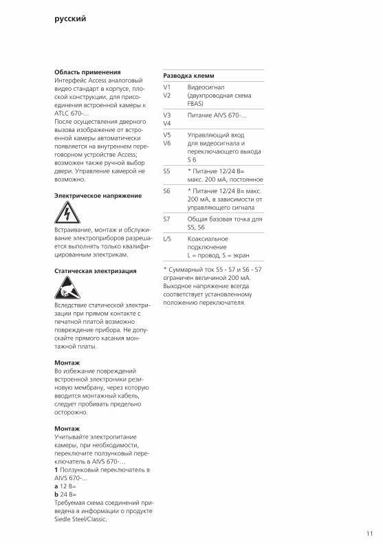
Разводка клемм
V1 V2
Видеосигнал (двухпроводная схема FBAS)
V3 V4
Питание AIVS 670-...
V5 V6
Управляющий вход для видеосигнала и переключающего выхода S 6
S5 * Питание 12/24 В= макс. 200 мА, постоянное
S6 * Питание 12/24 В= макс. 200 мА, в зависимости от управляющего сигнала
S7 Общая базовая точка для S5, S6
L/S Коаксиальное подключение L = провод, S = экран
* Суммарный ток S5 - S7 и S6 - S7 ограничен величиной 200 мА. Выходное напряжение всегда соответствует установленному положению переключателя.