displacement, and image to ground coordinate transformation
Principles of Photogrammetry Ayman F. Habib2
ENGO 431: Chapter 6
Image Coordinate Measurements
Principles of Photogrammetry Ayman F. Habib3
Overview• Image coordinate measurements in analogue,
analytical, and digital environments• Comparators: mono and stereo-comparators.• Automatic comparators• Comparator-to-image coordinate transformation• Reduction/refinement of image coordinate
measurements:– Radial and de-centering lens distortions– Atmospheric refraction– Earth curvature
Principles of Photogrammetry Ayman F. Habib4
Measurement and Reduction of Image Coordinates
• Objective of photogrammetry: – Derive ground coordinates of object points from
measured image coordinates
• Thus, photogrammetric processing starts with the measurement of image coordinates
• We are going to discuss how to perform this task in:– Analogue or analytical environment (i.e., using analogue
images)– Digital environment (i.e., using digital images)
Principles of Photogrammetry Ayman F. Habib5
Different Generations of Photogrammetry
Firs
t Gen
erat
ion
Ana
logu
e Ph
otog
ram
met
ry
Ana
lytic
al P
hoto
gr.
Dig
ital2000
1950
1900
1850
Invention of computer
Invention of airplane
Invention of photography
Principles of Photogrammetry Ayman F. Habib6
Different Generations of Photogrammetry
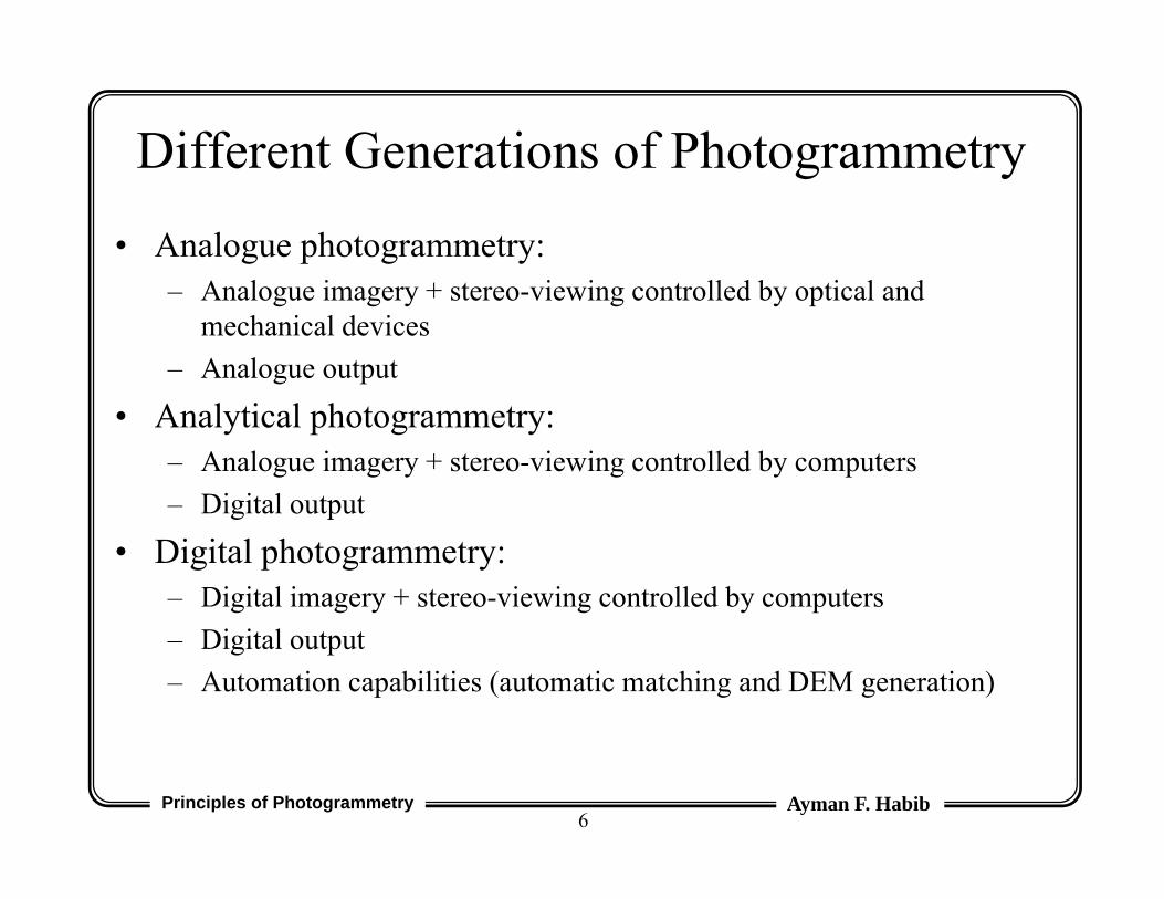
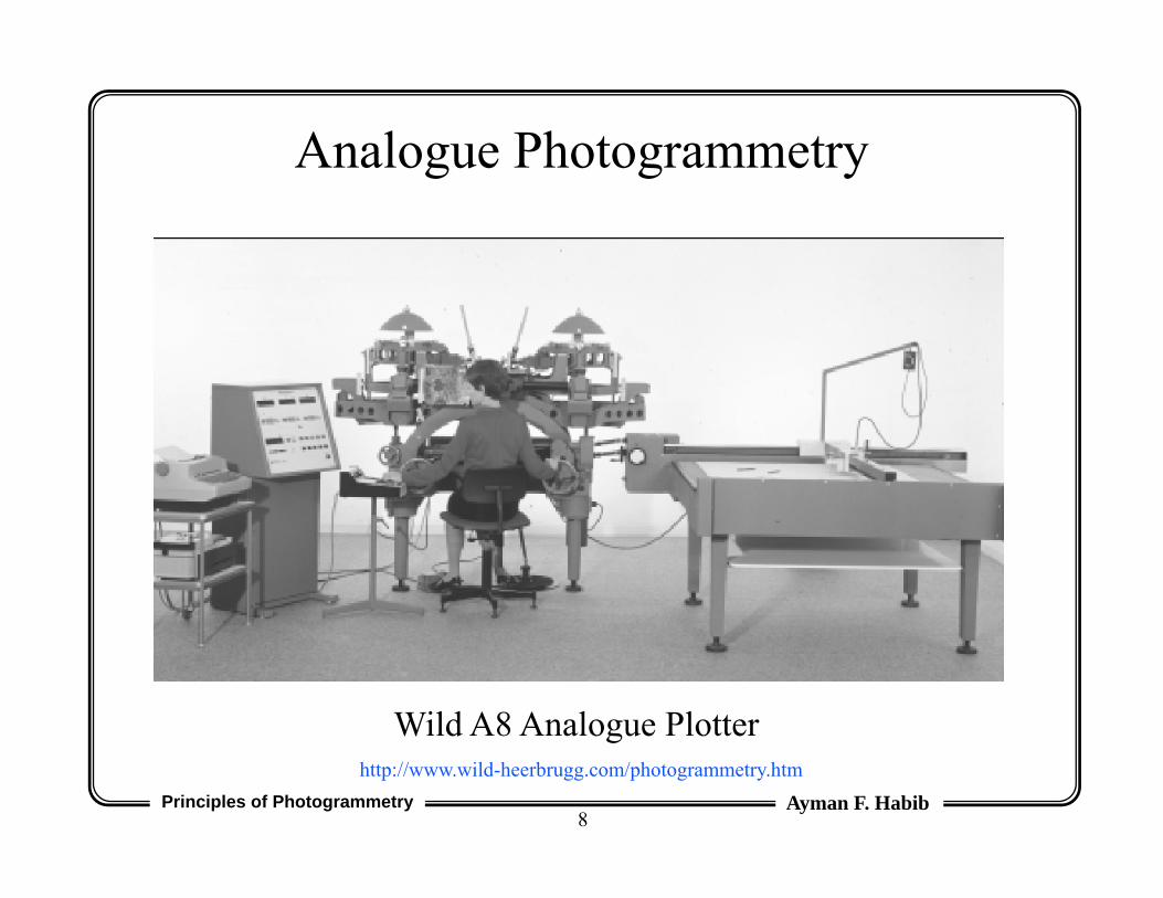
• Analogue photogrammetry:– Analogue imagery + stereo-viewing controlled by optical and
mechanical devices– Analogue output
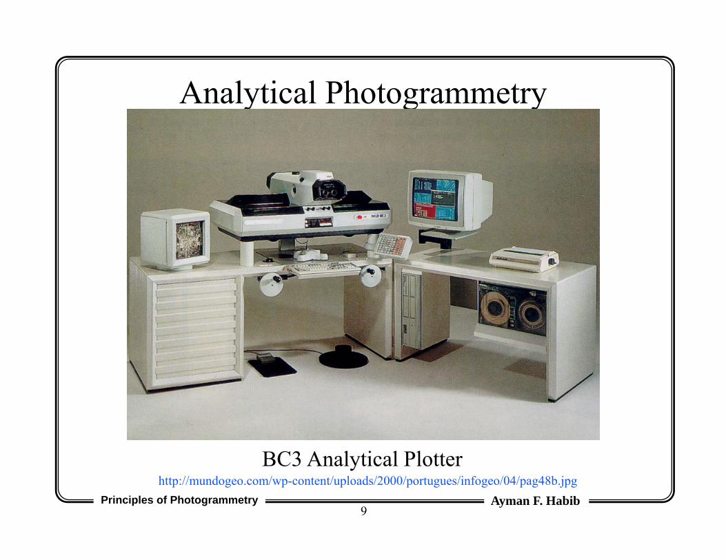
• Analytical photogrammetry:– Analogue imagery + stereo-viewing controlled by computers– Digital output
• Digital photogrammetry:– Digital imagery + stereo-viewing controlled by computers– Digital output– Automation capabilities (automatic matching and DEM generation)
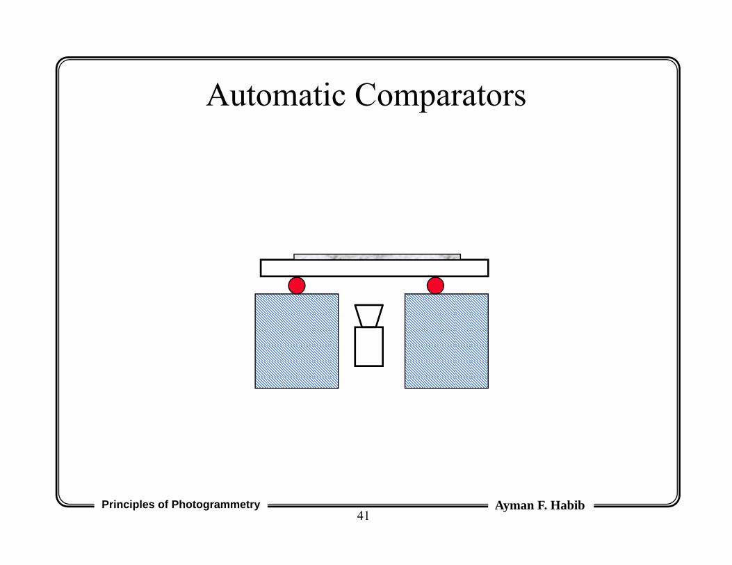
• Comparators are highly accurate machines for measuring the xy-coordinates of selected points in the image plane.
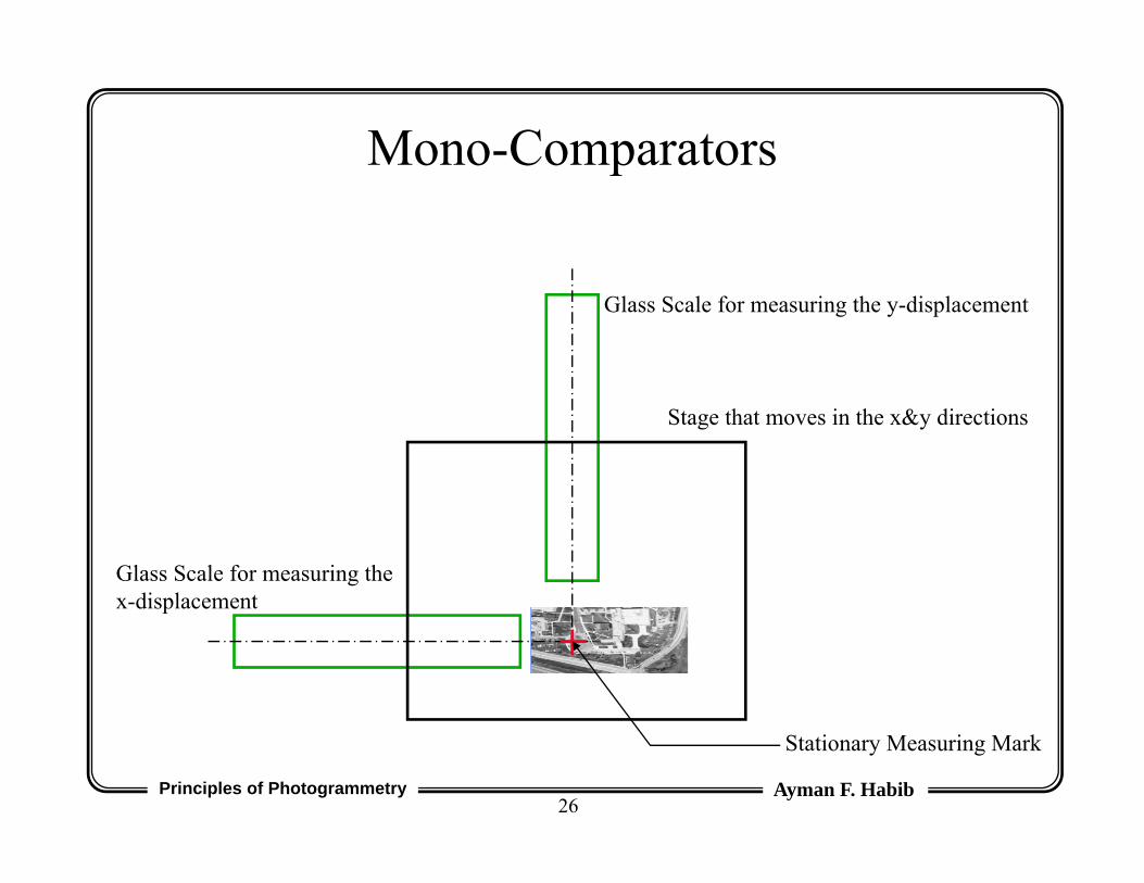
• Comparators can be classified into:– Mono-comparators: coordinates are measured in one
image at a time.– Stereo-comparators: coordinates are measured in a
stereo-pair simultaneously.
Principles of Photogrammetry Ayman F. Habib21
Stereo-Imaging
y-Parallax
Convergent Imagery
Principles of Photogrammetry Ayman F. Habib22
No y-parallax → Normal Case Imagery
Stereo-Imaging
Principles of Photogrammetry Ayman F. Habib23
Stereo-Comparators
xl
yl
px
py
Principles of Photogrammetry Ayman F. Habib24
Stereo-Comparators
• Two stages on top of which the two images of a stereo-pair are mounted.
• If no y-parallax exists, points can be selected and measured stereoscopically (i.e., in 3-D).
• Condition for stereoscopic viewing:– d and d between the two images are small.– Ensure that there is no vertical parallax.
Principles of Photogrammetry Ayman F. Habib25
Stereo-Comparators
• Measurements:– (x`l, y`l) stage coordinates in the left image– (px, py) offsets (parallax) to the conjugate point in the
right image
• x`r = px + x`l
• y`r = py + y`l
• Advantage: Points are selected stereoscopically → Higher accuracy → Less mis-matches.
• Disadvantage: Stereoscopic viewing is possible only if the rotation angles () are small.
Principles of Photogrammetry Ayman F. Habib26
Mono-Comparators
Glass Scale for measuring the y-displacement
Glass Scale for measuring the x-displacement
Stationary Measuring Mark
Stage that moves in the x&y directions
Principles of Photogrammetry Ayman F. Habib27
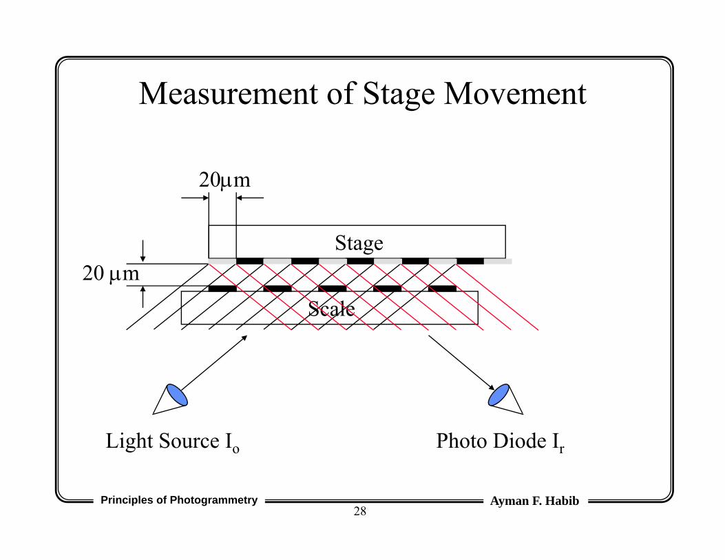
Light Source Io Photo Diode Ir
20m
Scale20 m
Measurement of Stage Movement
Stage
Principles of Photogrammetry Ayman F. Habib28
Light Source Io Photo Diode Ir
20m
Scale20 m
Stage
Measurement of Stage Movement
Principles of Photogrammetry Ayman F. Habib29
Measurement of Stage Movement
Principles of Photogrammetry Ayman F. Habib30
Ir/Io
d
0.5
40 m 160 m120 m80 m
Measurement of Stage Movement
Principles of Photogrammetry Ayman F. Habib31
• The number of maxima and minima in the current from the photo diode are proportional to the stage displacement.
• Using linear interpolation, we can measure displacements as small as 1m.
Measurement of Stage Movement
Principles of Photogrammetry Ayman F. Habib32
Abbe’s Rule
• The accuracy of the comparator depends on the spacing between the distance to be measured and the measuring scale.
• Abbe’s rule states that the distance to be measured and the measuring scale should be along a straight line (to achieve the highest accuracy possible).
Principles of Photogrammetry Ayman F. Habib33
Abbe’s Rule
d
d tan
Principles of Photogrammetry Ayman F. Habib34
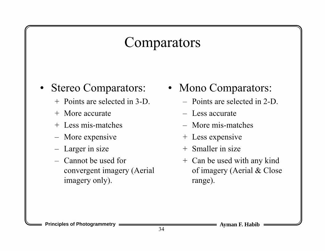
Comparators
• Stereo Comparators:+ Points are selected in 3-D.+ More accurate+ Less mis-matches– More expensive– Larger in size– Cannot be used for
convergent imagery (Aerial imagery only).
• Mono Comparators:– Points are selected in 2-D.– Less accurate– More mis-matches+ Less expensive+ Smaller in size+ Can be used with any kind
of imagery (Aerial & Close range).
Principles of Photogrammetry Ayman F. Habib35
Point Transfer Devices
• Point transfer devices physically mark the points on the emulsion using a needle or a small drill.
• Points are viewed stereoscopically.• Point transfer devices + mono-comparators will
yield an accuracy which is similar to that obtained from stereo-comparators.
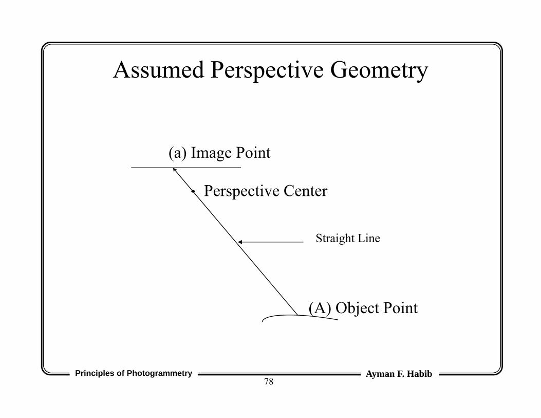
• Distortion parameters compensate for all the deviations from the assumed perspective geometry.
• Assumed perspective geometry:– Object point, perspective center, and the corresponding
image point lie on a straight line.
• Distortions include (for example):– Lens distortion (radial & de-centering)– Atmospheric refraction– Non-planar film platen
Principles of Photogrammetry Ayman F. Habib78
Assumed Perspective Geometry
(A) Object Point
(a) Image Point
Perspective Center
Straight Line
Principles of Photogrammetry Ayman F. Habib79
Radial Lens Distortion
Radial Lens Distortion
Actual Light Ray
Theoretical Light Ray
Principles of Photogrammetry Ayman F. Habib80
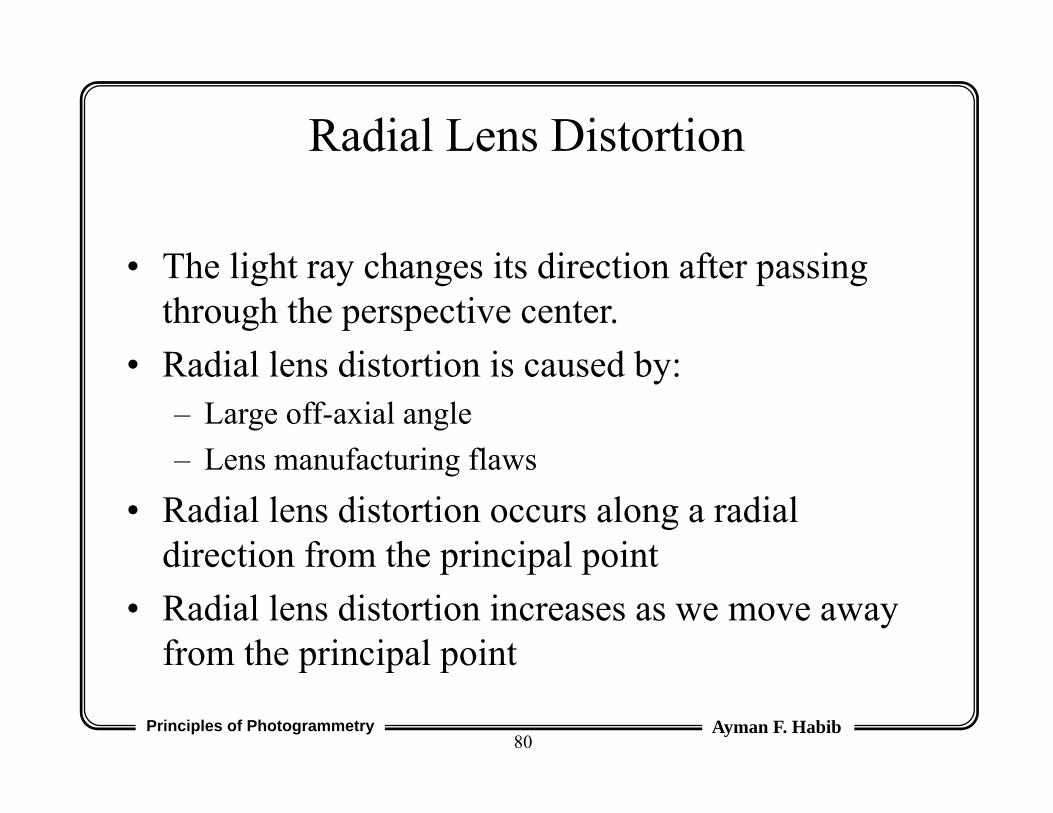
• The light ray changes its direction after passing through the perspective center.
• Radial lens distortion is caused by:– Large off-axial angle– Lens manufacturing flaws
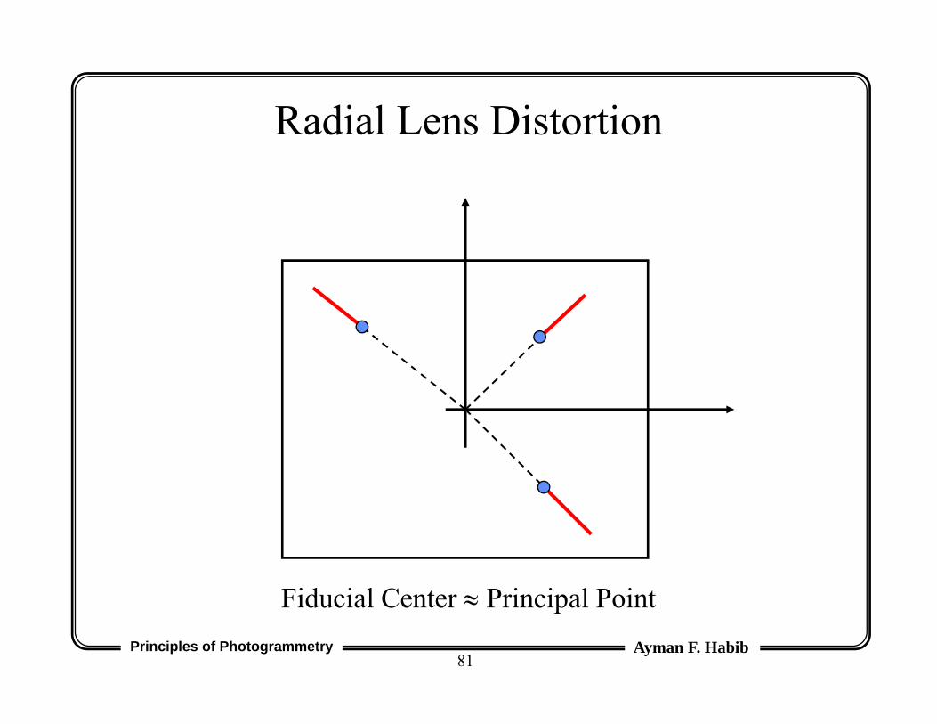
• Radial lens distortion occurs along a radial direction from the principal point
• Radial lens distortion increases as we move away from the principal point
Radial Lens Distortion
Principles of Photogrammetry Ayman F. Habib81
Fiducial Center Principal Point
Radial Lens Distortion
Principles of Photogrammetry Ayman F. Habib82
Pin Cushion Type Radial Lens DistortionWithout distortions With distortions
Radial Lens Distortion
Principles of Photogrammetry Ayman F. Habib83
Barrel Type Radial Lens DistortionWithout distortions With distortions
Radial Lens Distortion
Principles of Photogrammetry Ayman F. Habib84
Radial Lens Distortion
Principles of Photogrammetry Ayman F. Habib85
y
x(y-yp)
(x-xp)
r
r
x = r * (x - xp) / ry = r * (y - yp) / r
Radial Lens Distortion
Principles of Photogrammetry Ayman F. Habib86
• Radial lens distortion, r as a function of r, is available in the camera calibration certificate in either one of the following forms:– Graphical form,– Tabular form, or– Polynomial coefficients.
• Note: r is the radial distance between the principal point and the image point under consideration.
Radial Lens Distortion
Principles of Photogrammetry Ayman F. Habib87
)....()(
)....()(6
34
22
1
63
42
21
rkrkrkyyy
rkrkrkxxx
pDistortionLensRadial
pDistortionLensRadial
where: r = {(x - xp)2 + (y - yp)2}0.5
Radial Lens Distortion
Principles of Photogrammetry Ayman F. Habib88
After Removing Radial Lens Distortion
Principles of Photogrammetry Ayman F. Habib89
Lens Cone Assembly
Principles of Photogrammetry Ayman F. Habib90
De-centering Lens Distortion
• De-centering lens distortion is caused by mis-alignment of the components of the lens system.
• De-centering lens distortion has two components:– Radial component– Tangential component
Principles of Photogrammetry Ayman F. Habib91
Theoretical Optical Axis
Actual Optical Axis
De-centering Lens Distortion
Principles of Photogrammetry Ayman F. Habib92
De-centering Lens Distortion
Principles of Photogrammetry Ayman F. Habib93
o
P(r)
)cos()()sin()(3
.........)( 42
21
o
o
rPtrPr
rJrJrP
• P (r) is the profile along the axis with themaximum tangential distortion.
• is the direction of the axis with the maximumtangential distortion.
De-centering Lens Distortion
Principles of Photogrammetry Ayman F. Habib94
)}2(2{)1(
}2)2({)1(22
212
3
222
12
3
yrpyxprpy
yxpxrprpx
DistortionLensgDecenterin
DistortionLensgDecenterin
where: r = {(x - xp)2 + (y - yp)2}0.5
• p1 = -J1 sino.• p2 = J1 coso.• p3 = J2 / J1.
De-centering Lens Distortion
p
p
yyy
xxx
Principles of Photogrammetry Ayman F. Habib95
Without distortions With distortions
De-centering Lens Distortion
Principles of Photogrammetry Ayman F. Habib96
Camera Calibration Certificate: Example
• Wild Heerbrugg Instruments Inc• Camera type : Wild RC10• Identification number : 2061• Lens : Wild 15 UAG I• Identification Number : 6029• Calibrated Focal Length : C = 153.167 mm• Principal point coordinates in the Fiducial system:
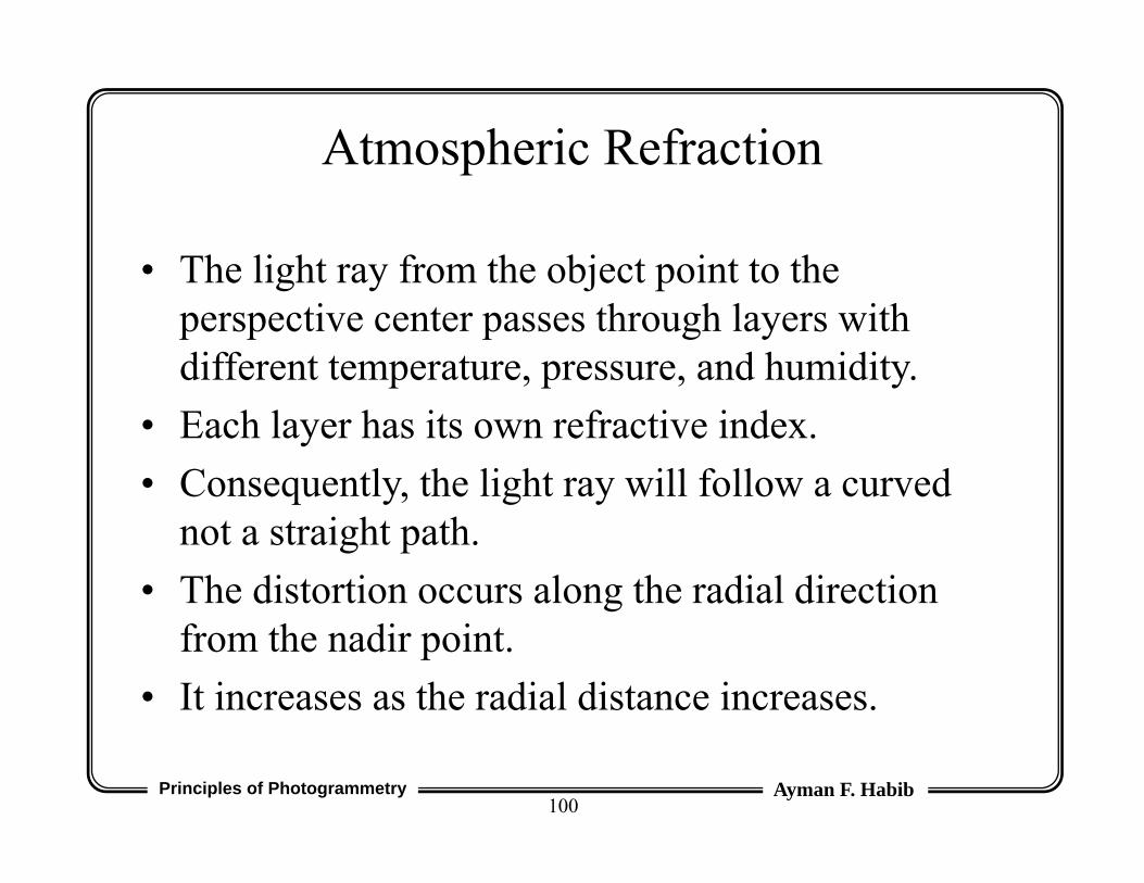
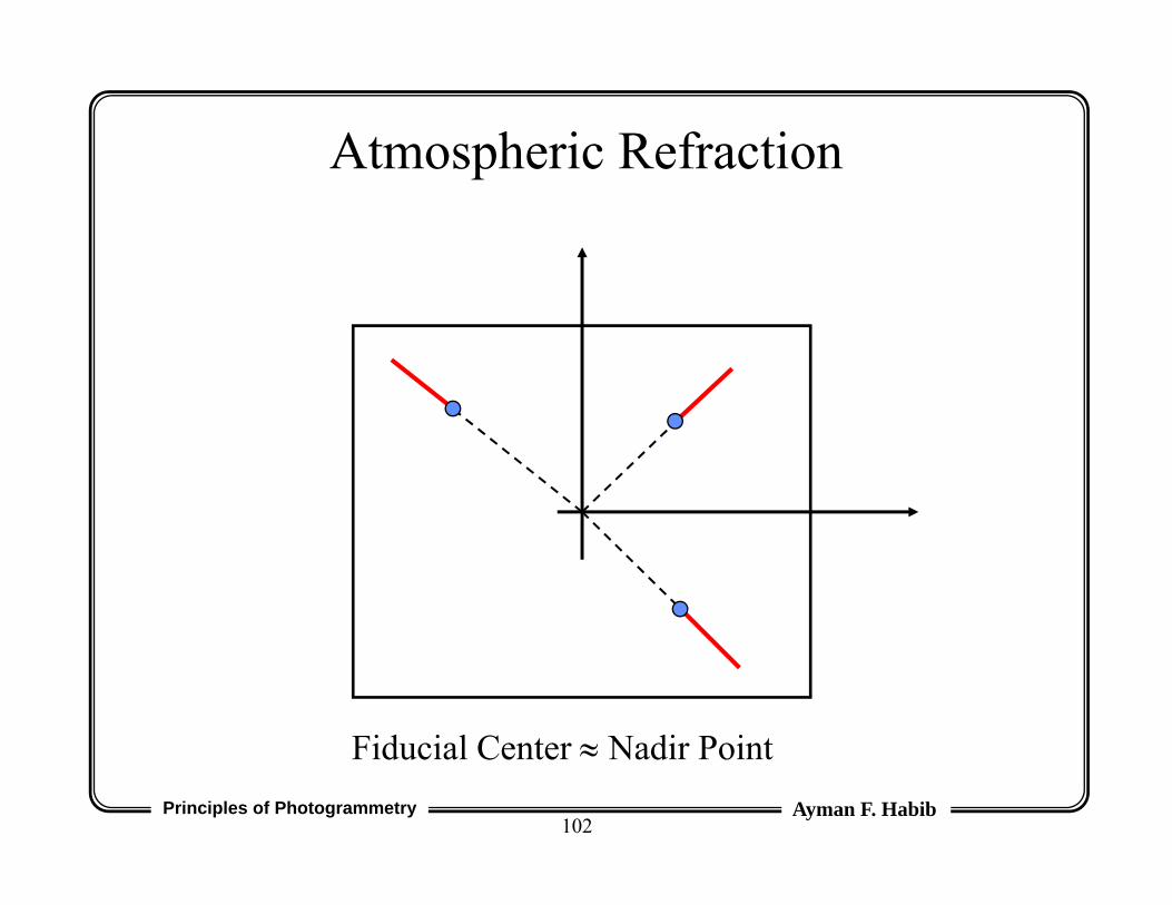
• The light ray from the object point to the perspective center passes through layers with different temperature, pressure, and humidity.
• Each layer has its own refractive index.• Consequently, the light ray will follow a curved
not a straight path.• The distortion occurs along the radial direction
from the nadir point.• It increases as the radial distance increases.
Principles of Photogrammetry Ayman F. Habib101
Actual Light Ray
Theoretical Light Ray
Atmospheric Refraction
Atmospheric Refraction
Principles of Photogrammetry Ayman F. Habib102
Fiducial Center Nadir Point
Atmospheric Refraction
Principles of Photogrammetry Ayman F. Habib103
• r = k r {1 + r2 / c2}• K is the atmospheric refraction coefficient.• Image points are always displaced outwardly
along the radial direction.• Correction (r) is always negative.• The above equation is only valid for almost
vertical photography.
Atmospheric Refraction
Principles of Photogrammetry Ayman F. Habib104
levelseatheaboveKminareZZWhere
ZZZZ
ZZZk
o
oo
o
o
&:
)2506(250600241.0 2
2
2
)1(
)1(
2
2
2
2
cryky
crxkx
Atmospheric Refraction
Principles of Photogrammetry Ayman F. Habib105
Earth Curvature
• It is not a problem with the image formation process (i.e., it is not a deviation from the assumed perspective geometry).
• It is a problem arising from the way we define the ground coordinate system.
• If the ground coordinates of the GCP are given relative to a true three-dimensional coordinate system, the curvature of the Earth’s surface is already taken into account.
Principles of Photogrammetry Ayman F. Habib106
Earth Curvature
• If the GCP is given relative to a map coordinate system (e.g., state plane and orthometric height), we have a problem with small scale imagery.– The Earth surface as reconstructed from the imagery is
a spheroid. – The Earth surface as defined by the GCP is flat.
• In this case, we have to distort the image coordinates in such a way that the Earth surface as reconstructed from the imagery is flat.
Principles of Photogrammetry Ayman F. Habib107
Earth Curvature Correction (Modification)
Actual Earth Surface
Assumed Earth SurfaceActual Light Ray
Theoretical Light Ray
Earth Curvature
Principles of Photogrammetry Ayman F. Habib108
• If we are dealing with a single image, and if this image is a true vertical image,
• Then, the image coordinates can be changed to compensate for the effect of Earth curvature
• In effect, we get the points depicted in the image plane as if the Earth surface had been totally flat.
distance principal cKm), (6370Earth theof radius R
point, principal thefrom distance radialrheight, flyingH
2 2
3
cRrHr
Earth Curvature
Principles of Photogrammetry Ayman F. Habib109
• r is always +ve.• Nowadays, the GCP are mainly provided by GPS
which provides us with true spatial coordinate system.
• Thus, we do not need to apply the earth curvature correction (modification).
Earth Curvature
Principles of Photogrammetry Ayman F. Habib110
Non Planar Film Platen
DistortionActual Film Platen
Theoretical Film Platen
Principles of Photogrammetry Ayman F. Habib111
r/c = dr/dhdr = dh * r/c
dhdr
r
c
Non Planar Film Platen
Principles of Photogrammetry Ayman F. Habib112
• dh: The deviation of the film platen from a perfect plane.
• Using height gages, dh can be measured and modeled by a high order polynomial.
• We can assure that the film is positioned tightly against the focal plane using either:– Glass plates (not recommended)– Suction mechanisms
Non Planar Film Platen
Principles of Photogrammetry Ayman F. Habib113
Reseau Camera
Principles of Photogrammetry Ayman F. Habib114
Reseau Camera
http://www.elcovision.com/e_elco_reseau.html
Principles of Photogrammetry Ayman F. Habib115
• Reseau: A raster of regularly spaced crosses marked on a glass plate in front of the film platen.
• The images of the crosses will appear on the final image.
• The image coordinates of the grid elements are available in the Camera Calibration Certificate (CCC).
• Comparing the image coordinates of the grid elements in both the image and the CCC, we can correct for the distortions that took place during film development.
Reseau Camera
Principles of Photogrammetry Ayman F. Habib116
Point Classification
• Points can be classified according to:– How do they appear in the imagery
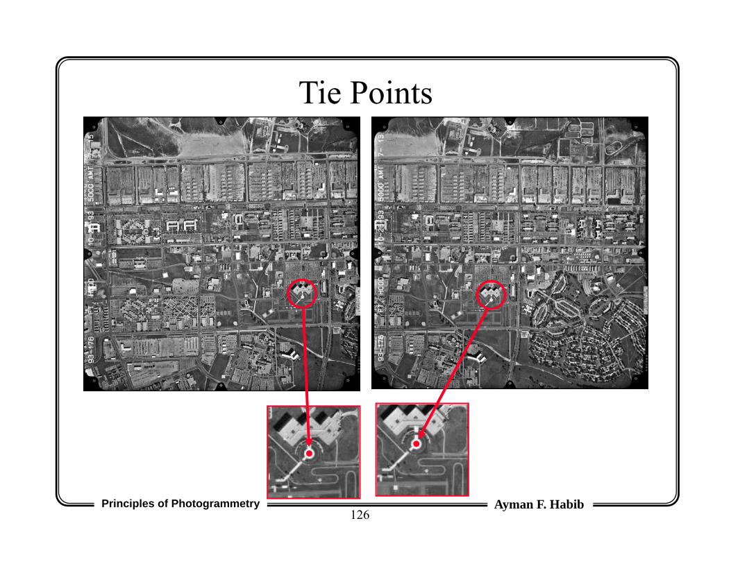
• Tie Points:– Their function is to tie together overlapping images.– They should be well defined in the images.– Their ground coordinates are determined through
photogrammetric adjustment.
Principles of Photogrammetry Ayman F. Habib126
Tie Points
Principles of Photogrammetry Ayman F. Habib127
Point Classification (II)
• Check Points:– Points whose ground coordinates are available from
geodetic measurements.– In the photogrammetric adjustment, they are used as tie
points.– By comparing the photogrammetric and geodetic
coordinates, one can check the quality of the photogrammetric adjustment.