AKM English Instructions Manual Deutsch Betriebsanleitung Italiano Manuale di Istruzioni Español Manual de Instrucciones Français Manuel d'Installation Русский Руководство по эксплуатации Edition June 2021 European Version (CE region) English Deutsch Italiano Español Français Русский Original Language is English. All other content is translated from the original language. Keep all manuals as a product component during the life span of the product. Pass all manuals to future users and owners of the product. Bewahren Sie alle Anleitungen während der gesamten Nutzungsdauer des Produkts als Produktkomponente auf. Händigen Sie alle Anlei- tungen künftigen Anwendern/Besitzern des Produkts aus. Conserve el manual durante toda la vida útil del producto. Entregue el manual a posteriores usuarios o propietarios del producto. Conservare il manuale per l’intera durata del prodotto. In caso di cam- bio di proprietà il manuale deve essere fornito al nuovo utilizzatore quale parte integrante del prodotto. Сохраняйте все руководства как составную часть продукта в течение всего срока его эксплуатации. Передавайте руководство следующему пользователю или владельцу продукта. Le manuel faisant partie intégrante du produit, conservez-le pendant toute la durée de vie du produit. Remettez le manuel au futur utilisateur ou propriétaire du produit.
Transcript
AKMEnglish Instructions ManualDeutsch BetriebsanleitungItaliano Manuale di IstruzioniEspañol Manual de InstruccionesFrançais Manuel d'InstallationРусский Руководство по эксплуатации
Edition June 2021European Version (CE region)
English Deutsch Italiano Español Français Русский
Original Language is English. All other content is translated from the original language.
Keep allmanuals asa product component during the lifespan of the product. Passallmanuals to future users andowners of the product.
Bewahren Sie alle Anleitungen während der gesamten NutzungsdauerdesProdukts alsProduktkomponente auf. Händigen Sie alle Anlei-tungen künftigen Anwendern/Besitzern desProdukts aus.
Conserve elmanual durante toda la vida útil del producto.Entregue elmanual a posterioresusuarios o propietarios delproducto.
Conservare ilmanuale per l’intera durata del prodotto. In caso di cam-bio di proprietà ilmanuale deve essere fornito al nuovo utilizzatorequale parte integrante del prodotto.
Сохраняйте все руководства как составную частьпродукта в течение всего срока его эксплуатации.Передавайте руководство следующемупользователюили владельцупродукта.
Lemanuel faisant partie intégrante du produit, conservez-le pendanttoute la durée de vie du produit. Remettez le manuel au futur utilisateurou propriétaire du produit.
Record of Document Revisions
Revision Remarks... Table with lifecycle information of this document ( # 218)06/2018 Thermal sensor KTY 83-110 replaced by PT1000, pin-outs updated10/2019 Holding brake chapter and data updated, total torque rise time and response time with AKD added,
dimensions of commcoder for AKM1 added, safety symbols updated, connector current updated--/2020 Brake data updated, Vibration and Shocks added,06/2021 Technical data AKM8 updated, Reference connectors updated, Brake data updated
Table of Contents
Instructions Manual English ( # 3) Technical Data ( # 173)
Manuale di Istruzioni Italiano ( # 59) Connector Pinout ( # 209)
Manual de Instrucciones Español ( # 87) Approvals ( # 216)
Manuel d'Installation Français ( # 115)
Руководство по эксплуатации Русский ( # 143)
Trademarks
l AKM is a registered trademark of Kollmorgen Corporationl EnDat is a registered trademark of Dr. Johannes Heidenhain GmbHl HIPERFACE is a registered trademark of Max StegmannGmbHl HIPERFACE DSL® is registered trademark of SICK STEGMANN GmbH.l DRIVE-CLiQ and SIMATIC are registered trademarks of SIEMENS Aktiengesellschaftl SpeedTec is a registered trademark of TE Connectivity Industrial GmbH
Technische Änderungen, die der Verbesserung der Geräte dienen, vorbehalten!Gedruckt in der BRD. Alle Rechte vorbehalten. Kein Teil des Werkes darf in irgendeiner Form (Fotokopie, Mikrofilmoder in einem anderen Verfahren) ohne schriftliche Genehmigung der Firma Kollmorgen Europe GmbH reproduziertoder unter Verwendung elektronischer Systeme verarbeitet, vervielfältigt oder verbreitet werden.Technical changes to improve the performance of the equipment may be made without prior notice!Printed in the Federal Republic of Germany. All rights reserved. No part of this work may be reproduced in any form(by photocopying, microfilm or any other method) or stored, processed, copied or distributed by electronic meanswithout the written permission of Kollmorgen Europe GmbH.Il produttore si riserva la facoltà di apportare modifiche tecniche volte al miglioramento degli apparecchiStampato nella Repubblica federale tedesca. Tutti i diritti riservati. Nessuna parte di questo documento può essererielaborata, riprodotta in qualsiasi forma (fotocopia, microfilm o altro processo) o diffusa mediante l'uso di sistemielettronici senza l'approvazione scritta della ditta Kollmorgen Europe GmbH o rielaborata, riprodotta o diffusa medi-ante l’uso di sistemi elettronici.Reservado el derecho de introducir modificaciones técnicas para la mejora de los equiposImpreso en la RFA. Reservados todos los derechos. Prohibida la reproducción total o parcial de la presente obra porcualquier medio (fotocopia, microfilm u otros), así como su procesamiento, reproducción y divulgación por medio desistemas electrónicos, sin expresa autorización escrita de la empresa Kollmorgen Europe GmbH.Toutes modifications techniques concourant pour l'amélioration des appareils réservées !Imprimé en Allemagne. Tous droits réservés. Aucune partie de l'ouvrage ne peut être reproduite sous quelque formeque ce soit (imprimée, photocopiée, microfilmée ou par un autre procédé) ou encore traitée, reproduite ou diffuséeau moyen de systèmes électroniques sans autorisation écrite préalable de Kollmorgen Europe GmbH.Сохраняется право вносить технические изменения, служащие для совершенствования устройств!Напечатано в ФРГ. Все права защищены. Без письменного согласия фирмы Kollmorgen Europe GmbHзапрещается воспроизводить какие бы то ни было части данного руководства в любой форме (в печатной, ввиде фотокопии, микрофильма или другим способом), а также обрабатывать, размножать или распространятьих с использованием электронных систем.
2 Kollmorgen | kdn.kollmorgen.com | June 2021
1 English
1.1 General 41.1.1 About this manual 41.1.2 Abbreviations used 41.1.3 Symbols Used 4
1.2 Safety 51.2.1 You should pay attention to this 51.2.2 Use as directed 61.2.3 Prohibited use 61.2.4 Handling 8
1.4 Technical Description 151.4.1 General technical data 151.4.2 Style 151.4.3 Flange 151.4.4 Protection class 151.4.5 Insulationmaterial class 161.4.6 Surface 161.4.7 Shaft end, A-side 161.4.8 Shaft seal 161.4.9 Protective device 171.4.10 Vibration class 171.4.11 Vibration and Shocks 171.4.12Wiring technology 181.4.13 Holding brake 191.4.14 Fan for AKM7 191.4.15Washdown andWashdown Food 20
1.5 Mechanical Installation 231.5.1 Important Notes 23
1.6 Electrical Installation 241.6.1 Important notes 241.6.2 Guide for electrical installation 251.6.3 Connection of themotors with preassembled cables 25
1.7 Setup 261.7.1 Important notes 261.7.2 Guide for setup 271.7.3 Trouble Shooting 28
1.8 Definition of Terms for Technical Data 29
AKM Installation | 1 English
Kollmorgen | kdn.kollmorgen.com | June 2021 3
AKM Installation | 1 English
1.1 General
1.1.1 About this manualThis manual describes the adjust in target series of synchronous servomotors (standard ver-sion). Themotors are operated in drive systems together with Kollmorgen servo drives.Please observe the entire system documentation, consisting of:
l Instructions manual for the servo drivel Manual Bus Communication (e.g. CANopen or EtherCAT)l Online help of the drive's setup softwarel Regional accessories manuall Technical description of the AKM series of motorsMore background information can be found on the Kollmorgen Developer Network, availableat kdn.kollmorgen.com.
1.1.2 Abbreviations usedAbbreviations used for technical data see chapter "Definition of terms" ( # 29).In this document, the symbolism ( # 53) means: see page 53.
1.1.3 Symbols UsedSymbol Indication
DANGERIndicates a hazardous situation which, if not avoided, willresult in death or serious injury.
WARNINGIndicates a hazardous situation which, if not avoided, couldresult in death or serious injury.
CAUTIONIndicates a hazardous situation which, if not avoided, couldresult in minor or moderate injury.
Indicates situations which, if not avoided, could result inproperty damage.
This symbol indicates important notes.
Warning of a danger (general). The type of danger is specifiedby the text next to the symbol.
Warning of danger from electricity and its effects.
1.2 SafetyThis section helps you to recognize and avoid dangers to people and objects.
1.2.1 You should pay attention to this
Specialist staff required!Only properly qualified personnel are permitted to perform such tasks as transport,assembly, setup andmaintenance. Qualified specialist staff are persons who are familiarwith the transport, installation, assembly, commissioning and operation of motors and whobring their relevant minimum qualifications to bear on their duties:
l Transport: only by personnel with knowledge of handling electrostatically sensitive com-ponents.
l Mechanical Installation: only by mechanically qualified personnel.l Electrical Installation: only by electrically qualified personnel.l Setup: only by qualified personnel with extensive knowledge of electrical engineering anddrive technology
The qualified personnel must know and observe IEC 60364 / IEC 60664 and national acci-dent prevention regulations.
Read the documentation!Read the available documentation before installation and commissioning. Improper handlingof themotor can cause harm to people or damage to property. The operator must thereforeensure that all persons entrusted to work on themotor have read and understood themanualand that the safety notices in this manual are observed.
Pay attention to the technical data!Adhere to the technical data and the specifications on connection conditions (rating plate anddocumentation). If permissible voltage values or current values are exceeded, themotorscan be damaged, for example by overheating.
Perform a risk assessment!Themanufacturer of themachinemust generate a risk assessment for themachine, and takeappropriate measures to ensure that unforeseenmovements cannot cause injury or damageto any person or property. Additional requirements on specialist staff may also result from therisk assessment.
Transport safely!Lift andmovemotors with more than 20 kg weight (AKM7 and AKM8) only with lifting tools.Lifting unassisted could result in back injury. Always observe the hints on ( # 8)
Secure the key!Remove any fitted key (if present) from the shaft before letting themotor run without coupledload, to avoid the dangerous results of the key being thrown out by centrifugal forces. Whendelivered, the key is protected with a plastic cap.
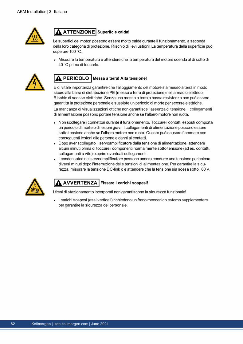
CAUTION Hot surface!
The surfaces of themotors can be very hot in operation, according to their protection cat-egory. Risk of minor burns! The surface temperature can exceed 100°C.
l Measure the temperature, and wait until themotor has cooled down below 40°C beforetouching it.
AKM Installation | 1 English
Kollmorgen | kdn.kollmorgen.com | June 2021 5
AKM Installation | 1 English
DANGER Earthing! High voltages!
It is vital that you ensure that themotor housing is safely earthed to the PE (protectiveearth) busbar in the switch cabinet. Risk of electric shock. Without low-resistance earthingno personal protection can be guaranteed and there is a risk of death from electric shock.Not having optical displays does not guarantee an absence of voltage. Power connectionsmay carry voltage even if themotor shaft is not rotating.
l Do not unplug any connectors during operation. There is a risk of death or severe injuryfrom touching exposed contacts. Power connections may be live even when themotorshaft is not rotating. This can cause flashovers with resulting injuries to persons and dam-age to the contacts.
l After disconnecting the servo drive from the supply voltage, wait several minutes beforetouching any components which are normally live (e.g. contacts, screw connections) oropening any connections.
l The capacitors in the servo drive can still carry a dangerous voltage several minutesafter switching off the supply voltages. To be quite safe, measure the DC-link voltageand wait until the voltage has fallen below 60 V.
WARNING Secure hanging loads!
Built-in holding brakes do not ensure functional safety!
l Hanging loads (vertical axes) require an additional, external mechanical brake to ensurepersonnel safety.
1.2.2 Use as directedl The AKM series of synchronous servomotors is designed especially for drives for indus-trial robots, machine tools, textile and packingmachinery and similar with high require-ments for dynamics.
l The user is only permitted to operate themotors under the ambient conditions which aredefined in this documentation.
l The use ofWashdownmotors is allowed in environments with caustic acids and baseswith respect to the defined conditions on page ( # 20).
l The use ofWashdown Foodmotors is allowed in applications with indirect contact tofood and beverage.
l The AKM series of motors is exclusively intended to be driven by servo drives underspeed and / or torque control.
l Themotors are installed as components in electrical apparatus or machines and can onlybe commissioned and put into operation as integral components of such apparatus ormachines.
l The thermal sensor which is integrated in themotor windings must be observed and eval-uated.
l The holding brakes are designed as standstill brakes and are not suited for repeated oper-ational braking.
l The conformity of the servo system to the standards mentioned in the CE Declaration ofConformity ( # 216) is only guaranteed when the components (servo drive, motor,cables etc.) that are used have been supplied by Kollmorgen.
1.2.3 Prohibited usel The use of theStandardMotors is prohibited
o directly onmains supply networks,o in areas where there is a risk of explosions,
6 Kollmorgen | kdn.kollmorgen.com | June 2021
o in contact with food and beverage,o in environments with caustic and/or electrically conducting acids, bases, oils, vapors,
dusts.l The use of theWashdownMotors is prohibited
o directly onmains supply networks,o in areas where there is a risk of explosions,o in contact with food and beverage,o in environments with acids or bases with pH value below 2 or above 12,o in environments with acids or bases that have not been tested by Kollmorgen.
l The use of theWashdown FoodMotors is prohibitedo directly onmains supply networks,o in areas where there is a risk of explosions,o in direct contact with food and beverage.
l Commissioning themotor is prohibited if themachine in which it was installedo does not meet the requirements of the EC Machinery Directive,o does not comply with the EMC Directive,o does not comply with the Low Voltage Directive.
l Built-in holding brakes without further equipment must not be used to ensure functionalsafety.
AKM Installation | 1 English
Kollmorgen | kdn.kollmorgen.com | June 2021 7
AKM Installation | 1 English
1.2.4 Handling
1.2.4.1 Transport
l Climate category 2K3 according to IEC 60721-3-2, EN61800-2l Temperature: -25...+70°C, max. 20K/hr changel Humidity: rel. humidity 5% - 95% , no condensationl Only by qualified personnel in themanufacturer’s original recyclable packagingl Avoid shocks, especially to the shaft endl If the packaging is damaged, check themotor for visible damage. Inform the car rier and, ifappropriate, themanufacturer.
Transport of motors with a weight of more than 20kgLifting eyes must be used to safely transport AKM7 and AKM8motors (> 20kg). Observe anytransport instructions included in the packaging of themotor.We recommend the transport tool ZPZM 120/292 for moving themotors.Suspension Unit ZPMZ 120/292 consists of a beam, suspended to the crane hook and twodouble-run chain suspenders.
DANGER Suspended load!
Risk of death if load falls. Never step under the load, while themotor is raised.
l The fastening screws of the lifting eyes must be fully screwed in.l The lifting eyes must be positioned on the supporting surface in an even and flat manner.l Prior to use, check the lifting eyes for secure fitting and any obvious damages (corrosion,deformation).
l Lifting eyes with deformations must not continue to be used.
8 Kollmorgen | kdn.kollmorgen.com | June 2021
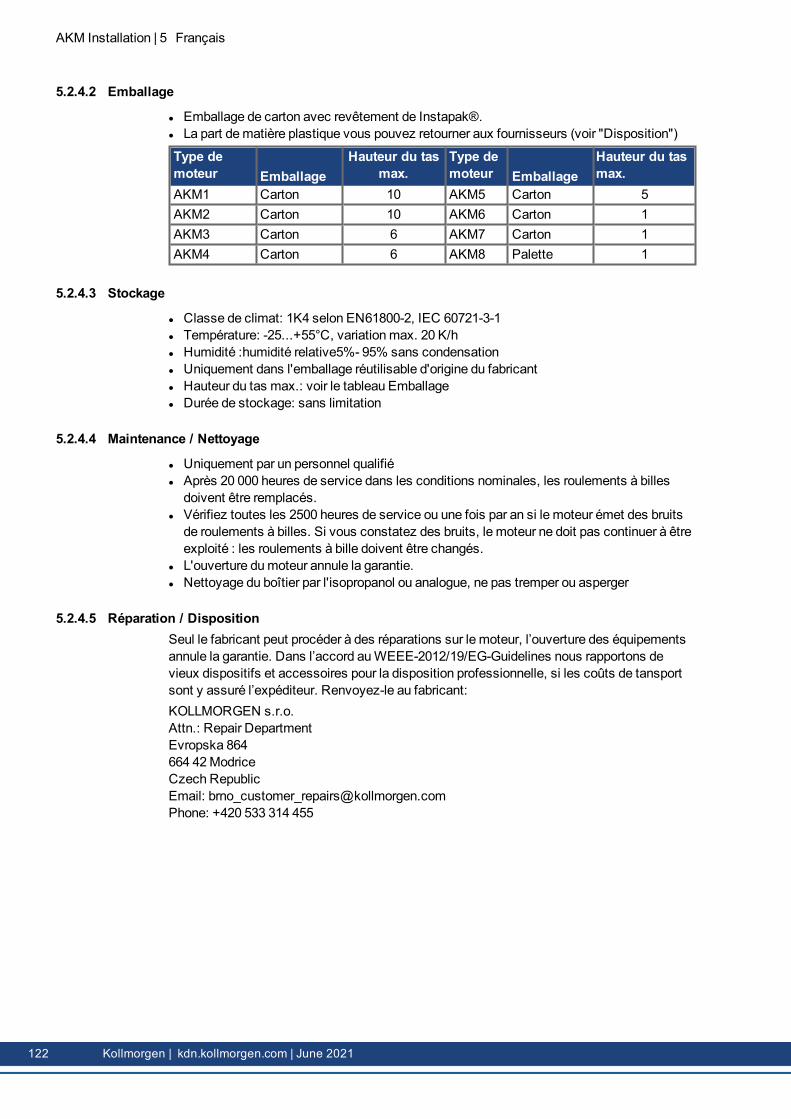
1.2.4.2 Packaging
l Cardboard packing with Instapak® foam cushion.l You can return the plastic portion to the supplier (see "Disposal").
l Climate category 1K4 according to IEC 60721-3-1, EN61800-2l Storage temperature: - 25...+55°C, max. variation 20K/hr.l Humidity: rel. humidity 5% - 95%, no condensationl Store only in themanufacturer’s original recyclable packagingl Max. stacking height: see table in chapter "Packaging"l Storage time: unlimited
1.2.4.4 Maintenance / Cleaning
l Maintenance and cleaning only by qualified personnell The ball bearings should be replaced after 20,000 hours of operation under rated conditions(by themanufacturer).
l Check themotor for bearing noise every 2500 operating hours, respectively each year. Ifany noises are heard, stop the operation of themotor, the bearings must be replaced (bythemanufacturer).
l Opening themotor invalidates the warranty.l If the housing is dirty, clean housing with Isopropanol or similar, do not immerse or spray
1.2.4.5 Repair / DisposalRepair of themotor must be done by themanufacturer. Opening themotor invalidates the war-ranty. In accordance to theWEEE-2012/19/EG-Guidelines we take old devices andaccessories back for professional disposal, if the transport costs are taken over by thesender. Send themotor to:KOLLMORGEN s.r.o.Attn.: Repair DepartmentEvropska 864664 42ModriceCzech RepublicEmail: [email protected]: +420 533 314 455
AKM Installation | 1 English
Kollmorgen | kdn.kollmorgen.com | June 2021 9
AKM Installation | 1 English
1.3 Package
1.3.1 Delivery packagel Motor from the AKM seriesl Product manual (multi language) printed, one per delivery
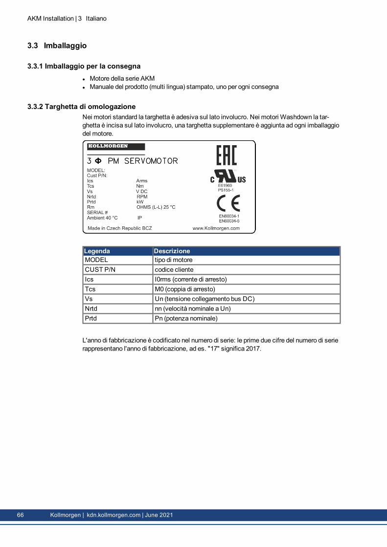
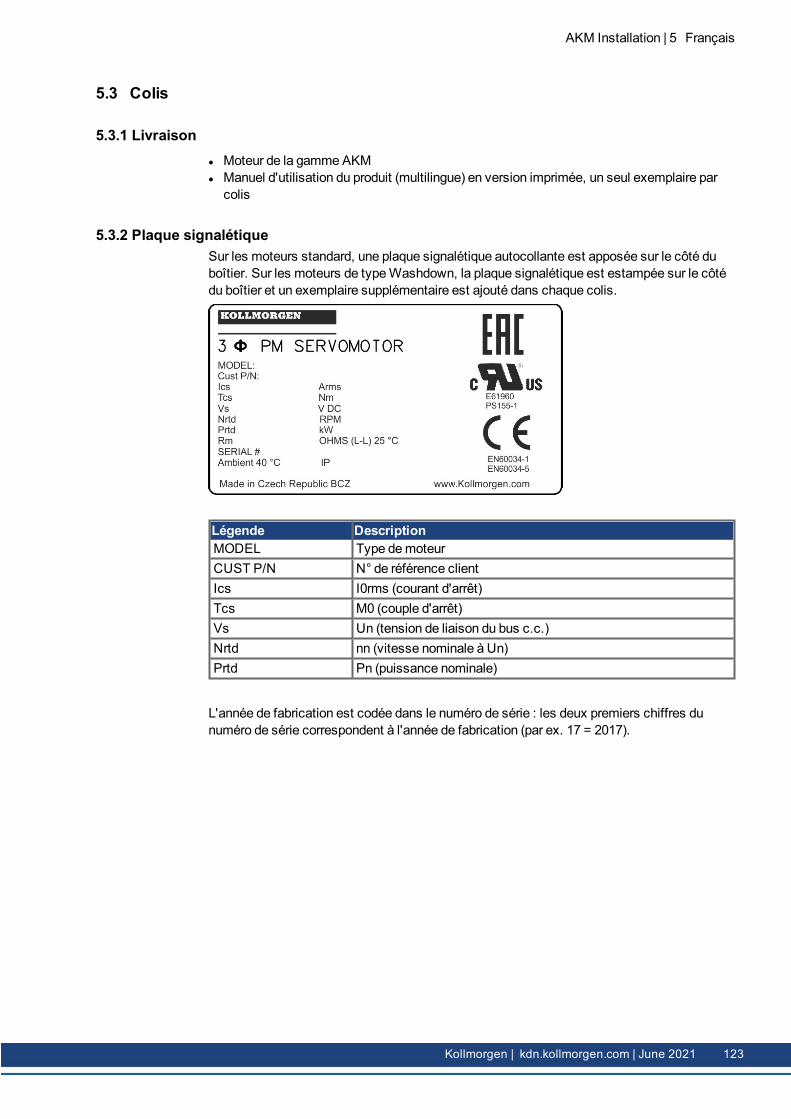
1.3.2 NameplateWith standardmotors the nameplate is adhesive on the housing side. With washdownmotors the nameplate is engraved on the housing side, an additional nameplate is added toevery motor package.
Legend DescriptionMODEL motor typeCUST P/N customer part no.Ics I0rms (standstill current)Tcs M0 (standstill torque)Vs Un (DC bus link voltage)Nrtd nn (rated speed@ Un)Prtd Pn (rated power)Rm R25 (winding resistance@ 25°)SERIAL serial no.AMBIENT maximum ambient temp.
Year of manufacturing is coded in the serial number: the first two digits of the serial numberare the year of manufacturing, e.g. "17" means 2017.
10 Kollmorgen | kdn.kollmorgen.com | June 2021
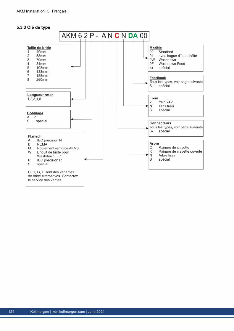
1.3.3 Model number description
AKM Installation | 1 English
Kollmorgen | kdn.kollmorgen.com | June 2021 11
AKM Installation | 1 English
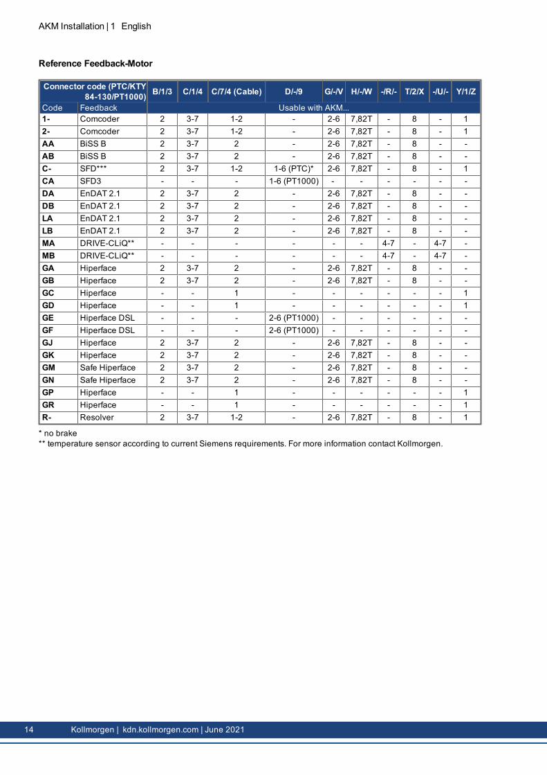
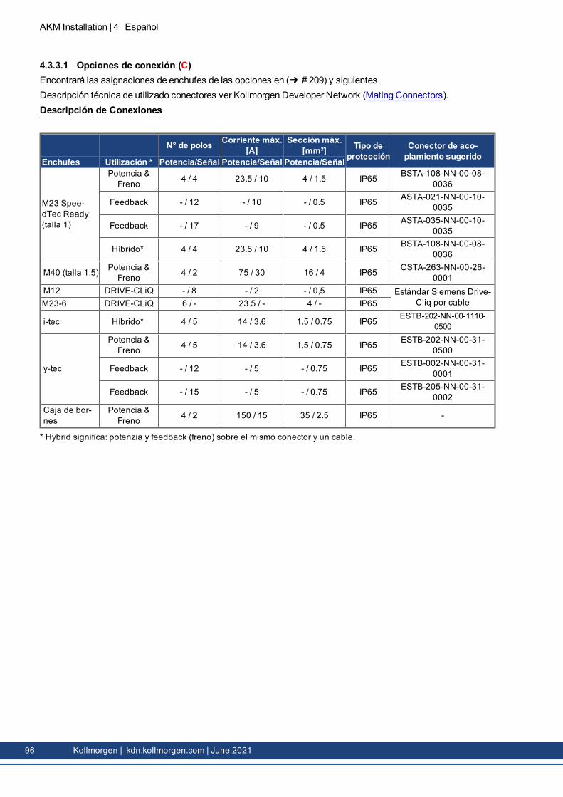
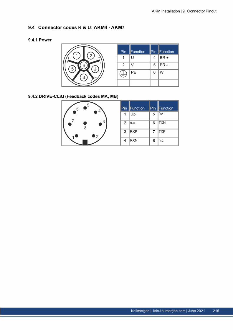
1.3.3.1 Connector Options (C)Technical description of used connectors see KDN (Mating Connectors).
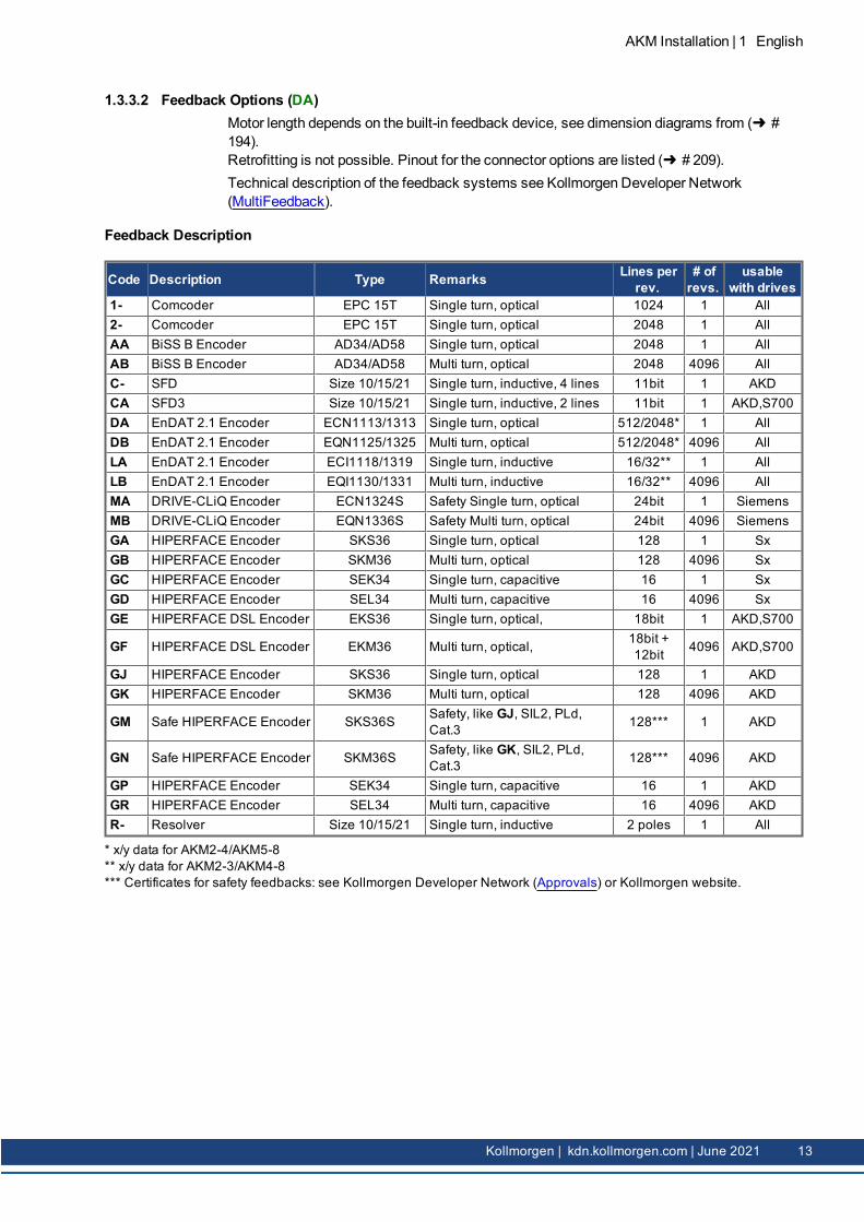
1.3.3.2 Feedback Options (DA)Motor length depends on the built-in feedback device, see dimension diagrams from ( #194).Retrofitting is not possible. Pinout for the connector options are listed ( # 209).Technical description of the feedback systems see Kollmorgen Developer Network(MultiFeedback).
Feedback Description
Code Description Type Remarks Lines perrev.
# ofrevs.
usablewith drives
1- Comcoder EPC 15T Single turn, optical 1024 1 All2- Comcoder EPC 15T Single turn, optical 2048 1 AllAA BiSS B Encoder AD34/AD58 Single turn, optical 2048 1 AllAB BiSS B Encoder AD34/AD58 Multi turn, optical 2048 4096 AllC- SFD Size 10/15/21 Single turn, inductive, 4 lines 11bit 1 AKDCA SFD3 Size 10/15/21 Single turn, inductive, 2 lines 11bit 1 AKD,S700DA EnDAT 2.1 Encoder ECN1113/1313 Single turn, optical 512/2048* 1 AllDB EnDAT 2.1 Encoder EQN1125/1325 Multi turn, optical 512/2048* 4096 AllLA EnDAT 2.1 Encoder ECI1118/1319 Single turn, inductive 16/32** 1 AllLB EnDAT 2.1 Encoder EQI1130/1331 Multi turn, inductive 16/32** 4096 AllMA DRIVE-CLiQ Encoder ECN1324S Safety Single turn, optical 24bit 1 SiemensMB DRIVE-CLiQ Encoder EQN1336S Safety Multi turn, optical 24bit 4096 SiemensGA HIPERFACE Encoder SKS36 Single turn, optical 128 1 SxGB HIPERFACE Encoder SKM36 Multi turn, optical 128 4096 SxGC HIPERFACE Encoder SEK34 Single turn, capacitive 16 1 SxGD HIPERFACE Encoder SEL34 Multi turn, capacitive 16 4096 SxGE HIPERFACE DSL Encoder EKS36 Single turn, optical, 18bit 1 AKD,S700
GN Safe HIPERFACE Encoder SKM36S Safety, like GK, SIL2, PLd,Cat.3 128*** 4096 AKD
GP HIPERFACE Encoder SEK34 Single turn, capacitive 16 1 AKDGR HIPERFACE Encoder SEL34 Multi turn, capacitive 16 4096 AKDR- Resolver Size 10/15/21 Single turn, inductive 2 poles 1 All
* x/y data for AKM2-4/AKM5-8** x/y data for AKM2-3/AKM4-8*** Certificates for safety feedbacks: see Kollmorgen Developer Network (Approvals) or Kollmorgen website.
* no brake** temperature sensor according to current Siemens requirements. For more information contact Kollmorgen.
14 Kollmorgen | kdn.kollmorgen.com | June 2021
1.4 Technical Description
1.4.1 General technical dataAmbient temperature(at rated values)
5...+40°C for site altitude up to 1000m amslIt is vital to consult our applications department for ambient tem-peratures above 40°C and encapsulatedmounting of themotors.
Permissible humidity(at rated values)
95% rel. humidity, no condensation
Power derating(currents and torques)
1%/K in range 40°C...50°C up to 1000m amslfor site altitude above 1000m amsl and 40°C6% up to 2000m amsl17% up to 3000m amsl30% up to 4000m amsl55% up to 5000m amslNo derating for site altitudes above 1000m amsl with tem-perature reduction of 10K / 1000m
Ball-bearing life ≥ 20.000 operating hours
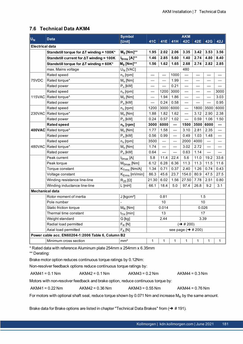
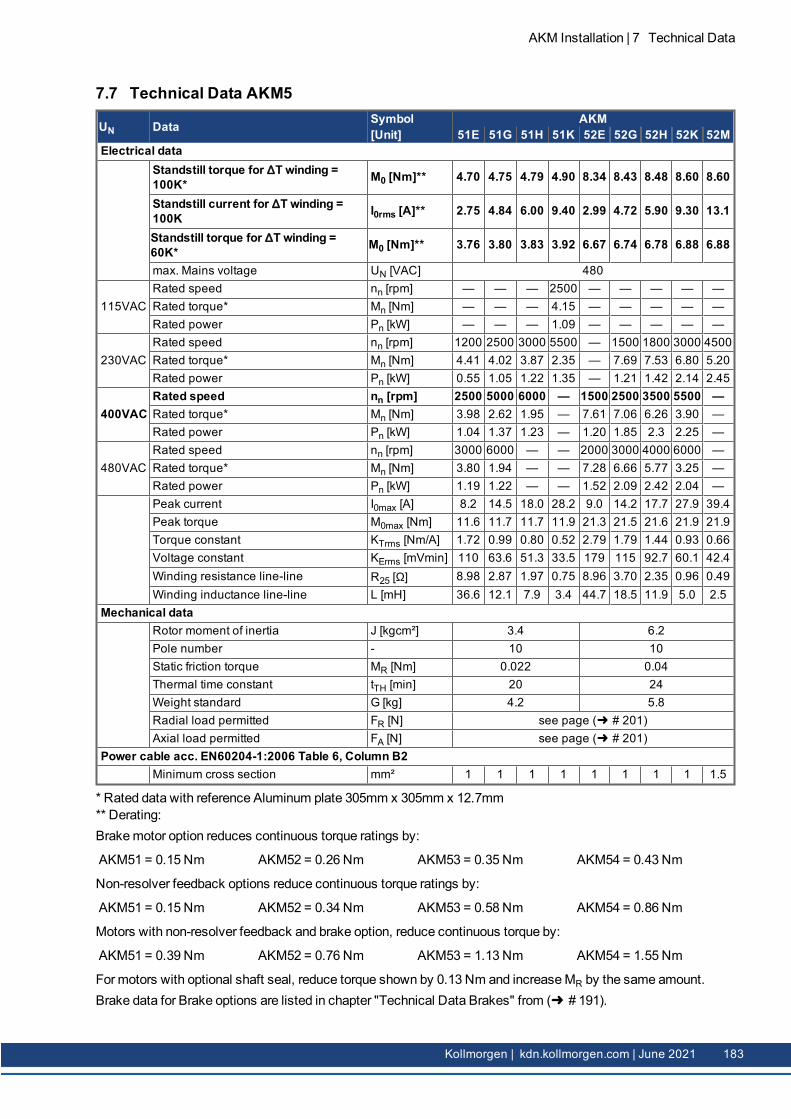
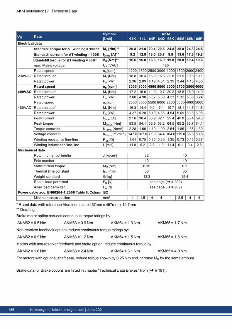
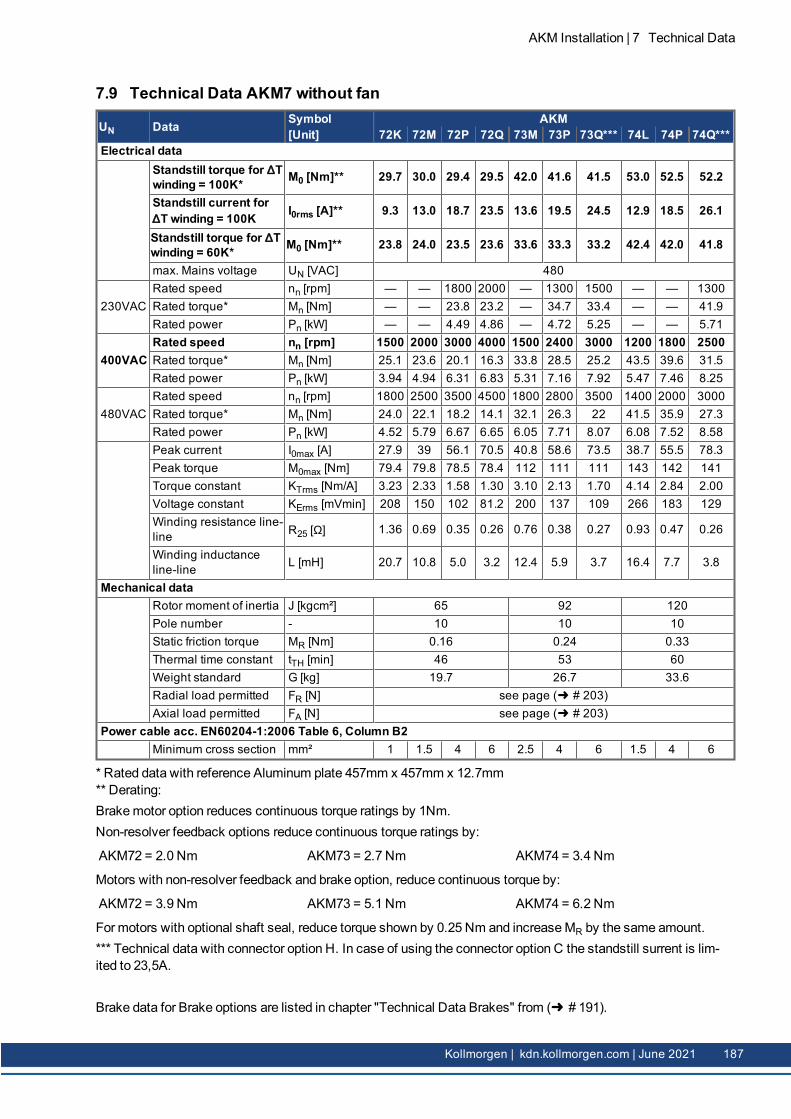
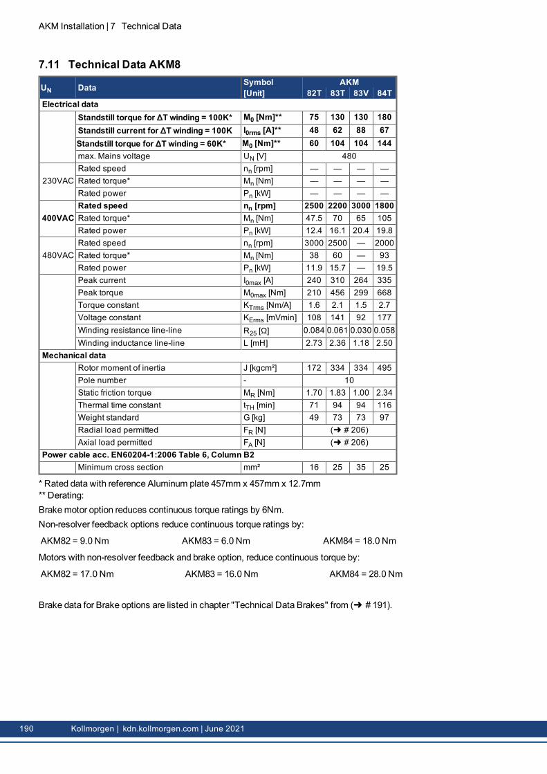
Technical data for every motor type can be found in chapter "Technical Data" from ( #173).
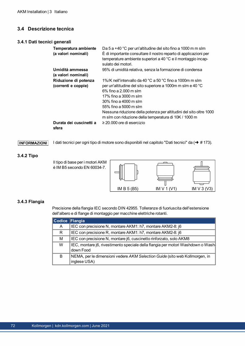
1.4.2 StyleThe basic style for the AKMmotors is style IM B5 accord-ing to EN 60034-7.
1.4.3 FlangeIEC flange accuracy according to DIN 42955. Tolerances of shaft extension run-out and ofmounting flanges for rotating electrical machines.
Code FlangeA IEC with accuracy N, fit AKM1: h7, fit AKM2-8: j6R IEC with accuracy R, fit AKM1: h7, fit AKM2-8: j6M IEC with accuracy N, fit j6, reinforced bearing, AKM8 onlyW IEC, fit j6,special flange coating forWashdown orWashdown FoodmotorsB NEMA, dimensions seeAKM Selection Guide (Kollmorgen website, US-English)
1.4.4 Protection classStandard Motor Connector Option Shaft Seal Protection classAKM1 C, D without IP40AKM1 C, D, Y with IP65AKM2-AKM7 B, C, D, G, H, T without IP54AKM8 H, T without IP52AKM2-AKM8 B, C, D, G, H, T with IP65AKM2-AKM6Washdown B, C, D, G with IP67AKM2-AKM6Washdown Food B, C, D, G with IP67
AKM Installation | 1 English
Kollmorgen | kdn.kollmorgen.com | June 2021 15
AKM Installation | 1 English
1.4.5 Insulation material classThemotors come up to insulationmaterial class F according to IEC 60085 (UL1446 class F).
1.4.6 SurfaceThemotors are coated with polyester powder coating in matte black. This finish is not res-istant against solvents (e.g. trichlorethylene, nitro-thinners, or similar).
1.4.7 Shaft end, A-sidePower transmission is made through the cylindrical shaft end A, fit k6 (AKM1: h7) toEN 50347, with a locking thread but without a fitted keyway.Motors are also available with keyway and inserted key according to DIN 6885. The shaftwith keyway is balanced with short (half) key.Bearing life is calculated with 20.000 operating hours.
Order code Shaft end Available forN Smooth shaft all types, standardC Keyway, closed AKM 2...8K Keyway, open AKM 1...8
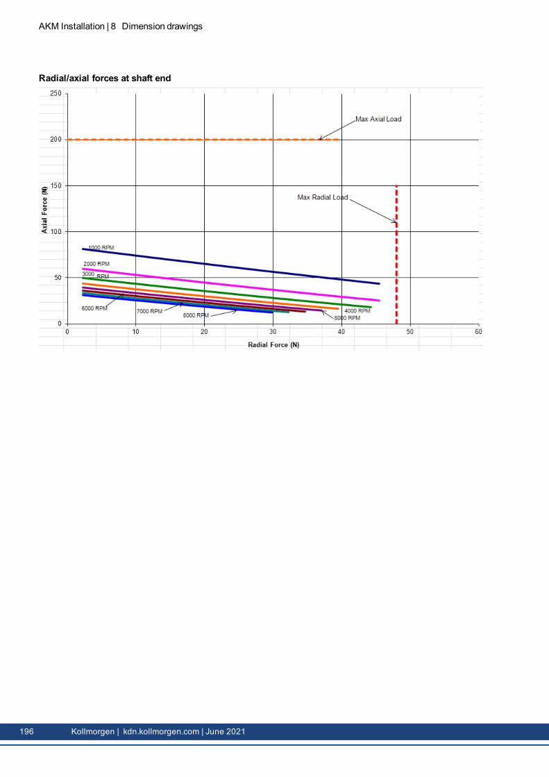
Radial forceIf themotors drive via pinions or toothed belts, then high radial forces will occur. The per-missible values at the end of the shaft may be read from the diagrams in chapter "Drawings"from ( # 194). Themaximum values at rated speed you will find at the technical data from( # 173). Power take-off from themiddle of the free end of the shaft allows a 10% increasein FR.
Axial forceWhen assembling pinions or wheels to the axis and use of e.g. angular gearheads axialforces arise. Themaximum values at rated speed are found in the technical data.
CouplingDouble-coned collets have proved to be ideal zero-backlash coupling devices, combined, ifrequired, with metal bellows couplings.
1.4.8 Shaft sealIf AKM is connected to amachine flange with unsealed shaft region, then the shaft seal(option "01") ensures the shaft sealing.
l The Teflon shaft seal ensures the IP67 protection for the shaft area.l The rated performance is achieved after some hours of shaft seal run-in. No special pro-cedure for run-in is needed.
l Some “shedding” of Teflonmaterial is normal and does not affect the function.l Shaft seal operation in dry-runningmode is prohibited. Contact Kollmorgen for specialshaft seal solution in case the dry-running operation is required.
l Shaft seal is pre-lubricated by FDA grease.
16 Kollmorgen | kdn.kollmorgen.com | June 2021
1.4.9 Protective deviceThe standard version of eachmotor is fitted with an electrically isolated PTC (ratedtemperature 155°C ± 5%). The PTC does not provide any protection against short, heavyoverloading.Themotor can be delivered with a PT1000 or KTY 84-130 sensors optionally (see ConnectorOptions 1, 2, 7 and D on ( # 209)( # 11).With digital feedback system SFD, SFD3, DSL (C-, CA, GE, GF) the temperature sensorstatus is transmitted digitally and evaluated in the drive.Provided that our configured feedback cables are used, the sensor is integrated into themon-itoring system of the digital servo drives.
1.4.10 Vibration classThemotors aremade to vibration class A according to EN 60034-14. For a speed range of600-3600 rpm and a shaft center between 56-132 mm, this means that the actual value of thepermitted vibration severity is 1.6 mm/s.
1.4.13 Holding brakeAll motors are optionally available with a holding brake. A spring applied brake (24V DC) isintegrated into themotors. When this brake is de-energized it blocks the rotor.
WARNING Secure hanging loads!
If there is a suspended load (vertical axes), themotor's holding brake is released, and, at thesame time, the servo drive does not produce any output, the loadmay fall down! Risk ofinjury exists for the personnel operating themachine.
l The user should consider required local safety standards in the case of hanging loads(vertical axes) and the need to insure personnel safety by using additional safety meas-ures for hazard avoidance.
The holding brakes are designed as standstill brakes and are not suited for repeated oper-ational braking. In the case of frequent, operational braking, premature wear and failure ofthe holding brake is to be expected.
Themotor length increases when a holding brake is mounted.The holding brake can be controlled directly by the servo drive (no personal safety !), the wind-ing is suppressed in the servo drive— additional circuitry is not required (see instructionmanual of the servo drive). If the holding brake is not controlled directly by the servo drive, anadditional wiring (e.g. varistor) is required. Consult our support department.Brake data are listed in chapter "Technical Data Brakes" from ( # 191) .
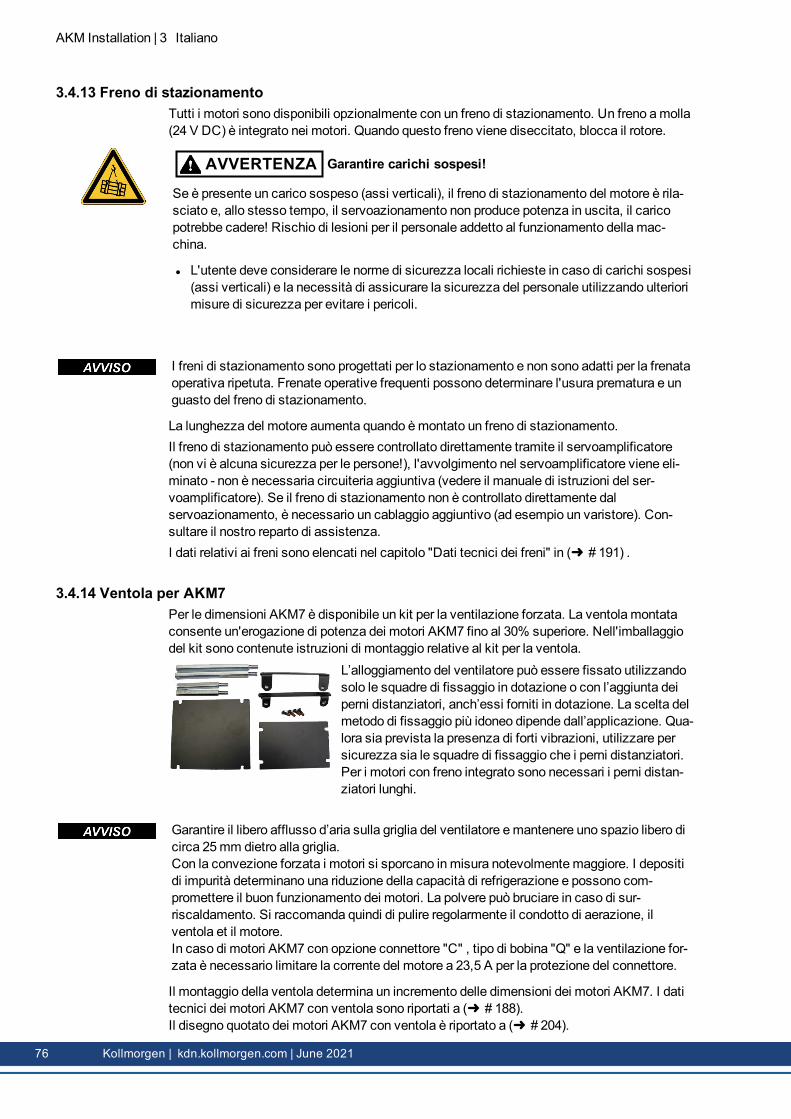
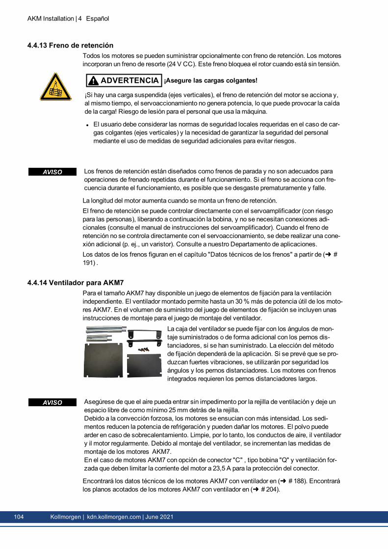
1.4.14 Fan for AKM7For the AKM7model size, an add-on kit for forced ventilation is available. The integrated fanenables up to 30% more power output for the AKM7motors. Assembly instructions for thefan kit is contained within the scope of delivery of the add-on kit.
The fan housing can bemounted either with both the suppliedbrackets and spacers or with the brackets only. The choice ofmountingmethod depends on the application. If strong vibra-tions are expected, you should use both brackets andspacers. Motors with integrated brakes require the longsspacers.
Make sure, that free air flow is available for the fan. Keep a space of at least 25mm behindthe fan guard.Themotors become dirty considerably faster due to forced convection. Dirt deposits lead tofalling cooling capacity and can put themotors at risk. Dust may burn in case of over-heating.So clean the air duct, the fan, and themotor at regular intervals.By adding a fan, themounting dimensions of AKM7motors increase.In case of AKM7motors with connector option "C", winding "Q" and forced ventilation youmust limit themotor current to 23,5 A for connector protection.
You can find technical information on AKM7motors with fans ( # 188).You can find the dimensional drawing for AKM7motors with fans on ( # 204).
AKM Installation | 1 English
Kollmorgen | kdn.kollmorgen.com | June 2021 19
AKM Installation | 1 English
1.4.15 Washdown and Washdown FoodThesemotor variants are used in applications that are subject to strict hygiene regulations inwhich it is essential that the formation of nucleation and corrosion are avoided and in whichmachines must be cleaned cyclically.Themotors are based on the standard types AKM2 - AKM6with special modifications for usein the food-processing industry or even in the packaging industry. In addition, it is also pos-sible to coat the flange in each case – but then it is not possible to assure tolerance class Nfor the flange.In the type code, the coating of themotor housing (type “W” forWashdown, "F" forWash-down Food) is defined separately in the version (last two digits) and the flange coating.
Washdown/WashdownFood Motor
ConnectorOptions
Suggested mating connector FlangeOptions
AKM2 B*, D*, G Option B, C, D, G (Hummel M23 INOX con-nectors):Power & Brake:7084943102Feedback 12-pin:7004912102Feedback 18-pin:7003917102
A, B, W, R
AKM3, 4, 6 C*, D*, G A, B, W, R
AKM5 C*, D*, G B, C, W
* Do not turn the connector on themotor more than +/- 180 °, greater rotation angle will dam-age the internal connections.
1.4.15.1 WashdownAKM^^^-^^^^^-^WAKM^^^-W^^^^^-^W
Washdownwithout flange coatingWashdownwith flange coating of IEC A flange
TheWashdownmotors must not come into contact with any unpacked foodstuffs.
Application Area: Harsh environments, outdoorsExample: Transport in the foodstuff and packing area without contact with
Washdown Food without flange coatingWashdown Food with flange coating of IEC A flange
The surface of theWashdown foodmotor has passed all tests as per FDA GlobalMigrationfor indirect contact with foodstuffs. Any direct contact with unpacked foodstuffs is not per-mitted.
Application Area: Foodstuffs and drinks industry, no direct contact with unpackedfoodstuff
Example: Cutting, packing and filling without direct contact with foodstuffs.Motor laterally or below the food.
Standards: UL, CE, RoHS, FDASurface: White coatingImmunity: Against tested industrial cleaning agent ( # 21), corrosion-proofGlobal Migration: US FDA Regulations 21 CFR 175.300, Condition of Use EDegree of protection: IP67Shaft: Stainless steelRotary shaft seal: PTFE as per FDALubricant: food-grade as per FDAConnector: Stainless steel, smooth surfaceScrews: Stainless SteelName plate: Engraved, additional nameplate in the packageSize: AKM2 - AKM6
1.4.15.3 Tested and confirmed properties with respect to cleaning agentsThe testing lab of ECOLAB DeutschlandGmbH tested the resistance of theWashdown andWashdown Food surfaces to the following industrial cleaning agents:
l P3-topactive DESl P3-topactive LAl P3-topax 56l P3-topax 66l P3-topax 91In the process, the surfaces were immersed in the respective cleaning agent at room tem-perature for 28 days. This corresponds to approx. 2,500 cleaning cycles with 15-minute con-tact each with the cleaning agent or 1,500 cleaning cycles with cleaning and subsequentdisinfection.The certificates are located in our Kollmorgen Developer Network on the Approvals page.
Kollmorgen can only give a guarantee for themotor's lifecycle if the tested cleansing agentsare used. Any cleansing agent other than thosementioned above can be tested by Koll-morgen upon request and, if appropriate, be approved.
l Themotors may be used only in ambient temperatures up to 50 °C.l If the front flange is coated, the tolerance class N is not guaranteed.
Motors with flanges without wash-down coating: The flange surfacemust be protected bysuitable assembly against the influence by cleaning agents.Duringmounting and operation protect themotor frommechanical effects which can causethe scratches or cracks on the painted surface.Themishandling increases risk of corrosion.
1.4.15.5 Cleaning planRecommended cleaning plan (short form) with tested cleaning agents:
Flushing with water (40 °... 50 °C)Flushing with low pressure. From top to bottom in the direction of the drain. Clean the drain.
Foam cleaningFoaming from top to bottom.Alkaline: P3-topactive LA or P3-topax 66 (2-5%, 15min daily)Acid: P3-topax 56 (2%, if necessary 15min)Temperature: cold up to 40 °C
DisinfectionSpraying with wayer (40 °... 50 °C) with low pressure. From top to bottom.Spray disinfection: P3-topax 91 (1-2%, if necessary 30-60min)Foam disinfection: P3-topactiv DES (1-3%, if necessary 10-30min)
22 Kollmorgen | kdn.kollmorgen.com | June 2021
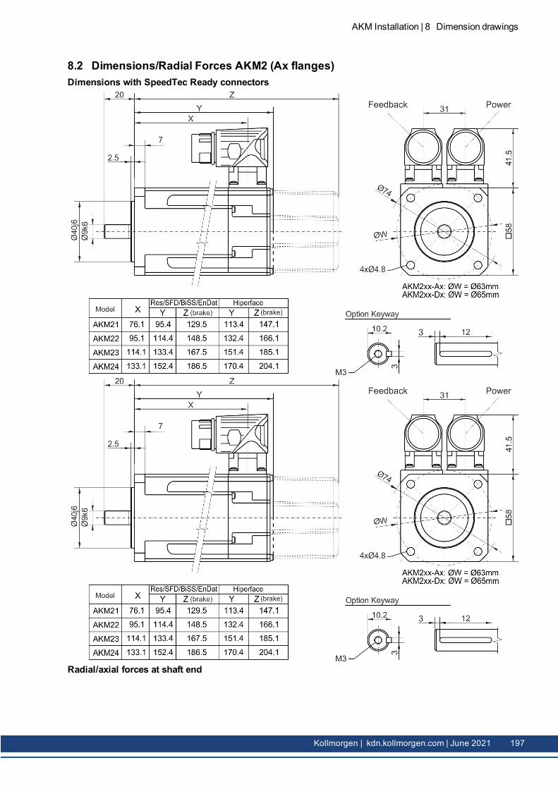
1.5 Mechanical InstallationDimension drawings can be found in chapter "Dimension Drawings"( # 194).
1.5.1 Important NotesOnly qualified staff with knowledge of mechanical engineering are permitted to assemble themotor.
l Protect themotor from unacceptable stresses. During transport and handling no com-ponents must be damaged.
l The site must be free of conductive and aggressivematerial. For V3-mounting (shaft endupwards), make sure that no liquids can enter the bearings. If an encapsulated assemblyis required, please consult Kollmorgen beforehand.
l Ensure an unhindered ventilation of themotors and observe the permissible ambient andflange temperatures. For ambient temperatures above 40°C please consult our applic-ations department beforehand. Ensure that there is adequate heat transfer in the sur-roundings and themotor flange.
l Motor flange and shaft are especially vulnerable during storage and assembly - so avoidbrute force. It is important to use the locking thread which is provided to tighten up coup-lings, gear wheels or pulley wheels and warm up the drive components, where possible.Blows or the use of force will lead to damage to the bearings and the shaft.
l Wherever possible, use only backlash-free, frictionally-locking collets or couplings.Ensure correct alignment of the couplings. A displacement will cause unacceptable vibra-tion and the destruction of the bearings and the coupling.
l In all cases, do not create amechanically constrainedmotor shaft mounting by using arigid coupling with additional external bearings (e.g. in a gearbox).
l Take note of the no. of motor poles and the no. of resolver poles (if applicable), and ensurethat the correct setting is made in the servo drive which is used. An incorrect setting canlead to the destruction of themotor, especially with small motors.
l Avoid axial loads on themotor shaft, as far as possible. Axial loading significantlyshortens the life of themotor.
l Check the compliance to the permitted radial and axial forces FR and FA. When you use atoothed belt drive, theminimal permitted diameter of the pinione.g. follows from the equation: dmin ≥ (M0/FR)*2
AKM Installation | 1 English
Kollmorgen | kdn.kollmorgen.com | June 2021 23
AKM Installation | 1 English
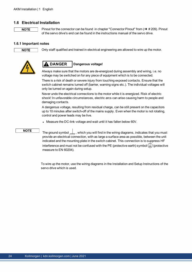
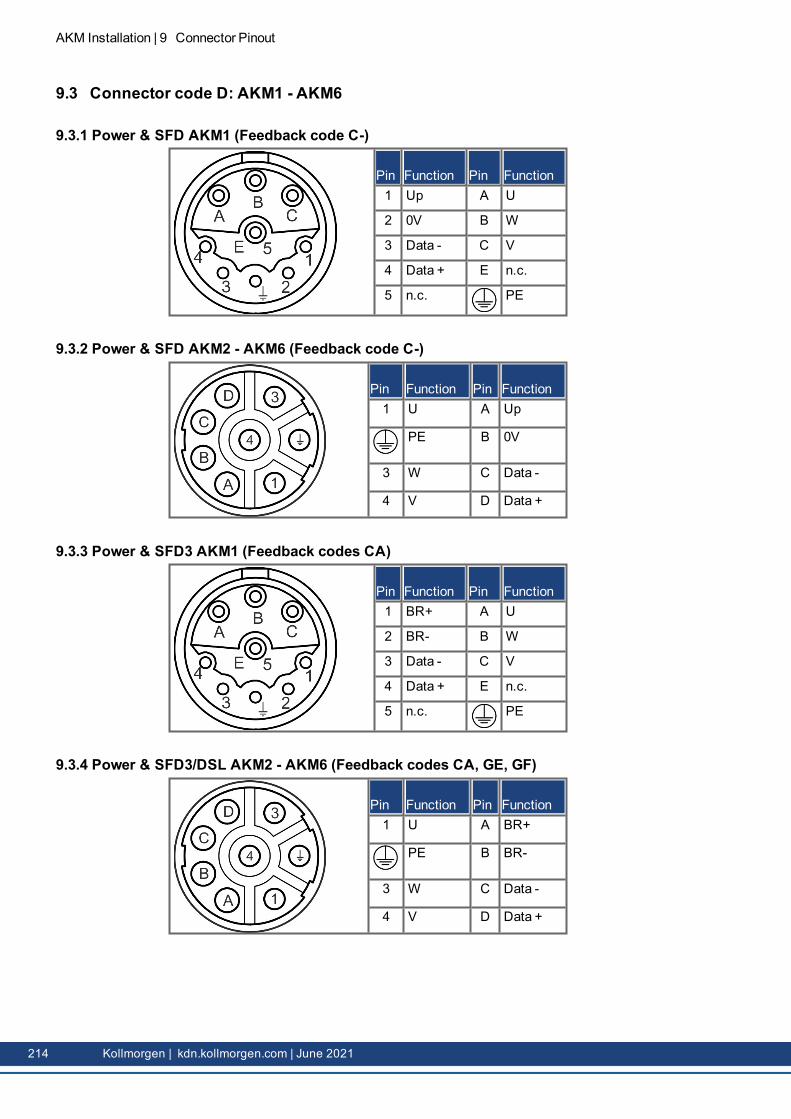
1.6 Electrical InstallationPinout for the connector can be found in chapter "Connector Pinout" from ( # 209). Pinoutof the servo drive's end can be found in the instructions manual of the servo drive.
1.6.1 Important notesOnly staff qualified and trained in electrical engineering are allowed to wire up themotor.
DANGER Dangerous voltage!
Always make sure that themotors are de-energized during assembly and wiring, i.e. novoltagemay be switched on for any piece of equipment which is to be connected.There is a risk of death or severe injury from touching exposed contacts. Ensure that theswitch cabinet remains turned off (barrier, warning signs etc.). The individual voltages willonly be turned on again during setup.Never undo the electrical connections to themotor while it is energized. Risk of electricshock! In unfavorable circumstances, electric arcs can arise causing harm to people anddamaging contacts.A dangerous voltage, resulting from residual charge, can be still present on the capacitorsup to 10minutes after switch-off of themains supply. Even when themotor is not rotating,control and power leads may be live.
l Measure the DC-link voltage and wait until it has fallen below 60V.
The ground symbol , which you will find in the wiring diagrams, indicates that youmustprovide an electrical connection, with as large a surface area as possible, between the unitindicated and themounting plate in the switch cabinet. This connection is to suppress HFinterference andmust not be confused with the PE (protective earth) symbol (protectivemeasure to EN 60204).
To wire up themotor, use the wiring diagrams in the Installation and Setup Instructions of theservo drive which is used.
24 Kollmorgen | kdn.kollmorgen.com | June 2021
1.6.2 Guide for electrical installationl Check that the servo drive andmotor match each other. Compare the rated voltage andrated current of the unit. Carry out the wiring according to the wiring diagram in the instruc-tions manual of the servo drive. The connections to themotor are shown in chapter "Con-nector Pinout" from ( # 209).
l Install all cables carrying a heavy current with an adequate cross-section, as perEN 60204. The recommended cross-section can be found in the Technical data.
In case of longmotor cables (>25m) and dependent on the type of the used servo drive amotor choke (3YL or 3YLN)must be switched into themotor cable (see instructions manualof the servo drive and accessory manual).
l Ensure that there is proper earthing of the servo drive and themotor. Use correct earthingand EMC-shielding according to the instructions manual of the servo drive which is used.Earth themounting plate andmotor casing.
l If a motor power cable is used which includes integral brake control leads, then thesebrake control leads must be shielded. The shieldingmust be connected at both ends (seeinstructions manual of the servo drive).
l Cabling:o Route power cables as separately as possible from control cableso Connect the feedback device.o Connect themotor cables, install motor chokes (if applicable) close to the driveo Connect shields to shielding terminals or EMC connectors at both endso Connect the holding brake, if usedo Connect shielding at both ends.
l Connect up all shielding via a wide surface-area contact (low impedance) andmetallizedconnector housings or EMC-cable glands.
l Requirements to cablematerial:CapacityMotor cable: less than 150 pF/mResolver cable: less than 120 pF/m
1.6.3 Connection of the motors with preassembled cablesl Carry out the wiring in accordance with the valid standards and regulations.l Only use Kollmorgen preassembled shielded cables for the resolver and power con-nections.
l Incorrectly installed shielding leads to EMC interference and has an adverse effect on sys-tem function.
l Themaximum cable length is defined in the instructions manual of the used servo drive.
For a detailed description of configured cables, please refer to the regional accessoriesmanual.
AKM Installation | 1 English
Kollmorgen | kdn.kollmorgen.com | June 2021 25
AKM Installation | 1 English
1.7 Setup
1.7.1 Important notesOnly specialist personnel with extensive knowledge in the areas of electrical engineering /drive technology are allowed to commission the drive unit of servo drive andmotor.
CAUTION Hot surface!
The surface temperature of themotor can exceed 100°C in operation. Danger of light burns!
l Check (measure) the temperature of themotor.l Wait until themotor has cooled down below 40°C before touching it.
DANGER High voltages!
Deadly voltages can occur, up to 900 V. Risk of electric shock! Check that all live con-nection points are safe against accidental contact.Never undo the electrical connections to themotor when it is live. Risk of electric shock!The residual charge in the capacitors of the drive can produce dangerous voltages up to 10minutes after themains supply has been switched off.Even when themotor is not rotating, control and power leads may be live.
l Measure the DC-link voltage and wait until it has fallen below 60 V.
CAUTION Secure unplanned movements!
The drive performing unplannedmovements during commissioning cannot be ruled out.
l Make sure that, even if the drive starts to move unintentionally, no danger can result forpersonnel or machinery.
l Themeasures youmust take in this regard for your task are based on the risk assess-ment of the application.
26 Kollmorgen | kdn.kollmorgen.com | June 2021
1.7.2 Guide for setupThe procedure for setup is described as an example. A different methodmay be appropriate or neces-sary, depending on the application of the equipment.
1. Check the assembly and orientation of themotor.2. Check the drive components (clutch, gear unit, belt pulley) for the correct seating and set-
ting (observe the permissible radial and axial forces).3. Check the wiring and connections to themotor and the servo drive. Check that the earth-
ing is correct.4. Test the function of the holding brake, if used. (apply 24 V, brakemust be released).5. Check whether the rotor of themotor revolves freely (release the brake, if necessary).
Listen for grinding noises.6. Check that all the requiredmeasures against accidental contact with live andmoving parts
have been carried out.7. Carry out any further tests which are specifically required for your system.8. Now commission the drive according to the setup instructions for the servo drive.9. In multi-axis systems, individually commission each drive unit (drive andmotor).
AKM Installation | 1 English
Kollmorgen | kdn.kollmorgen.com | June 2021 27
AKM Installation | 1 English
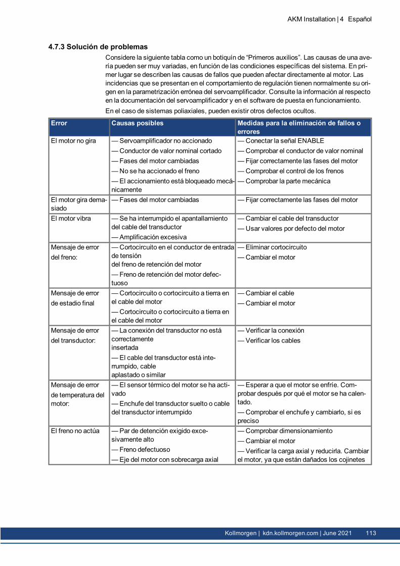
1.7.3 Trouble ShootingThe following table is to be seen as a “First Aid” box. There can be a large number of differentreasons for a fault, depending on the particular conditions in your system. The fault causesdescribed below aremostly those which directly influence themotor. Peculiarities whichshow up in the control loop behaviour can usually be traced back to an error in the para-meterization of the servo drive. The documentation for the servo drive and the setup softwareprovides information on thesematters.For multi-axis systems theremay be further hidden reasons for faults.
Fault Possible causeMeasures to remove the causeof the fault
Motor doesn’trotate
—Servodrive not enabled—Break in setpoint lead—Motor phases in wrong sequence—Brake not released—Drive is mechanically blocked
Motor runs away —Motor phases in wrong sequence —Correct the phase sequenceMotor oscillates —Break in the shielding of the resolver
cable— drive gain to high
—Replace resolver cable— usemotor default values
Error message:brake
—Short-circuit in the supply voltagelead to themotor holding brake—Faulty motor holding brake
—Remove the short-circuit
—ReplacemotorError message:output stagefault
—Motor cable has short-circuit or earthshort—Motor has short-circuit or earth short
—Replace cable—Replacemotor
Error message:resolver
—Resolver connector is not properlyplugged in—Break in resolver cable, cablecrushed or similar
—Check connector
—Check cables
Error message:motor tem-perature
—Motor thermosensor has switched
— Loose resolver connector or break inresolver cable
—Wait until themotor hascooled down. Then investigatewhy themotor becomes so hot.—Check connector, replaceresolver cable if necessary
Brake does notgrip
—Required holding torque too high—Brake faulty—Motor shaft axially overloaded
—Check the dimensioning—Replacemotor—Check the axial load, reduceit. Replacemotor, since the bear-ings have been damaged
28 Kollmorgen | kdn.kollmorgen.com | June 2021
1.8 Definition of Terms for Technical DataTechnical data for every motor type can be found in chapter "Technical Data" ( # 173).
All data valid for 40°C environmental temperature and 100K overtemperature of the winding.Determination of nominal data with constant temperature of adapter flange of 65°C. The datacan have a tolerance of +/- 10%.
Standstill torque M0 [Nm]The standstill torque can bemaintained indefinitely at a speed 0<n<100 rpm and rated ambi-ent conditions.
Rated torque Mn [Nm]The rated torque is produced when themotor is drawing the rated current at the rated speed.The rated torque can be produced indefinitely at the rated speed in continuous operation (S1).
Standstill current I0rms [A]The standstill current is the effective sinusoidal current which themotor draws at 0<n<100rpm to produce the standstill torque.
Peak current (pulse current) I0max [A]The peak current (effective sinusoidal value) is several times the rated current depending onthemotor winding. The actual value is determined by the peak current of the drive which isused.
Torque constant KTrms [Nm/A]The torque constant defines how much torque in Nm is produced by themotor with 1A r.m.s.current. The relationship is M=I x KT (up to I = 2 x I0).
Voltage constant KErms [mV/min-1]
The voltage constant defines the inducedmotor EMF, as an effective sinusoidal valuebetween two terminals, per 1000 rpm. Measured at 25°C.
Rotor moment of inertia J [kgcm²]The constant J is ameasure of the acceleration capability of themotor. For instance, at I0 theacceleration time tb from 0 to 3000 rpm is given as:
with M0 in Nm and J in kgcm²
Thermal time constant tth [min]The constant tth defines the time for the coldmotor, under a load of I0, to heat up to an over-temperature of 0.63 x 10⁵ Kelvin. This temperature rise happens in amuch shorter time whenthemotor is loaded with the peak current.
Release delay time tBRH [ms] / Engage delay time tBRL [ms] of the brakeThese constants define the response times of the holding brake when operated with the ratedvoltage from the servo drive.
UN
Ratedmains voltage
Un
DC-Bus link voltage.
AKM Installation | 1 English
Kollmorgen | kdn.kollmorgen.com | June 2021 29
--- / ---
AKM Installation | 1 English
30 Kollmorgen | kdn.kollmorgen.com | June 2021
2 Deutsch
2.1 Allgemeines 322.1.1 Zu diesem Handbuch 322.1.2 Verwendete Abkürzungen 322.1.3 Verwendete Symbole 32
2.2 Sicherheit 332.2.1 Darauf sollten Sie achten 332.2.2 Bestimmungsgemäße Verwendung 352.2.3 Nicht bestimmungsgemäße Verwendung 352.2.4 Handhabung 36
2.6 Elektrische Installation 532.6.1Wichtige Hinweise 532.6.2 Leitfaden für die elektrische Installation 542.6.3 Anschluss der Motorenmit vorkonfektionierten Leitungen 54
2.7 Inbetriebnahme 552.7.1Wichtige Hinweise 552.7.2 Leitfaden für die Inbetriebnahme 562.7.3 Beseitigen von Störungen 57
2.8 Begriffsdefinitionen für technische Daten 58
AKM Installation | 2 Deutsch
Kollmorgen | kdn.kollmorgen.com | June 2021 31
AKM Installation | 2 Deutsch
2.1 Allgemeines
2.1.1 Zu diesem HandbuchDieses Handbuch beschreibt die Synchron-Servomotoren der Serie adjust in target (Stan-dardausführung). DieMotoren werden in Antriebssystemen zusammenmit Servoverstärkernvon Kollmorgen betrieben. Beachten Sie daher die gesamte Dokumentation des Systems,bestehend aus:
l Betriebsanleitung des Servoverstärkersl Manuelle Buskommunikation (z. B. CANopen oder EtherCAT)l Online-Hilfe der Inbetriebnahmesoftware des Servoverstärkersl Regionales Zubehörhandbuchl Technische Beschreibung der Motorserie AKMWeitere Hintergrundinformationen finden Sie im Kollmorgen Developer Network unter kdn.-kollmorgen.com.
2.1.2 Verwendete AbkürzungenDie Abkürzungen für die technischen Daten finden Sie im Kapitel „Begriffsdefinitionen“. ( #58).In diesem Dokument bedeutet die Symbolik ( S. 53): siehe Seite 53.
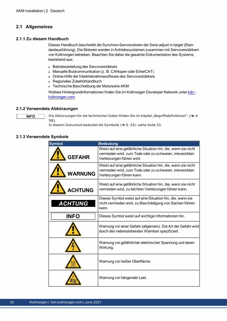
2.1.3 Verwendete SymboleSymbol Bedeutung
GEFAHRWeist auf eine gefährliche Situation hin, die, wenn sie nichtvermieden wird, zum Tode oder zu schweren, irreversiblenVerletzungen führen wird.
WARNUNGWeist auf eine gefährliche Situation hin, die, wenn sie nichtvermieden wird, zum Tode oder zu schweren, irreversiblenVerletzungen führen kann.
ACHTUNGWeist auf eine gefährliche Situation hin, die, wenn sie nichtvermieden wird, zu leichten Verletzungen führen kann.
Dieses Symbol weist auf eine Situation hin, die, wenn sienicht vermieden wird, zu Beschädigung von Sachen führenkann.
Dieses Symbol weist auf wichtige Informationen hin.
Warnung vor einer Gefahr (allgemein). Die Art der Gefahr wirddurch den nebenstehendenWarntext spezifiziert.
Warnung vor gefährlicher elektrischer Spannung und derenWirkung.
2.2 SicherheitDieser Abschnitt hilft Ihnen, Gefahren für Personen und Sachwerte zu erkennen und zu ver-meiden.
2.2.1 Darauf sollten Sie achten
Fachpersonal ist erforderlich!Nur qualifiziertes Personal darf Arbeiten wie Transport, Montage, Inbetriebnahme undWar-tung ausführen. Qualifiziertes Fachpersonal sind Personen, die mit dem Transport, der Instal-lation, der Montage, der Inbetriebnahme und dem Betrieb vonMotoren vertraut sind und ihrejeweiligenMindestqualifikationen einbringen:
l Transport: nur durch Personal, das für den Umgangmit elektrostatisch empfindlichen Bau-teilen geschult ist.
l Mechanische Installation: nur durch Fachleutemit maschinenbautechnischer Ausbildung.l Elektrische Installation nur durch Fachleutemit elektrotechnischer Ausbildung.l Inbetriebnahme: nur durch Fachleutemit weitreichenden Kenntnissen in den BereichenElektrotechnik/Antriebstechnik.
Das Fachpersonal muss die Normen IEC 60364/IEC 60664 und die nationalen Unfall-verhütungsvorschriften kennen und beachten.
Lesen Sie die Dokumentation sorgfältig durch!Lesen Sie vor der Installation und Inbetriebnahme die vorliegende Dokumentation. Unsach-gemäßeHandhabung des Motors kann zu Personen- oder Sachschäden führen. Der Betrei-ber muss daher sicherstellen, dass alle mit Arbeiten amMotor betrauten Personen dasHandbuch gelesen und verstanden haben und dass die Sicherheitshinweise in diesem Hand-buch beachtet werden.
Beachten Sie die technischen Daten!Halten Sie die technischen Daten und die Angaben zu den Anschlussbedingungen (Typen-schild und Dokumentation) ein. Werden zulässige Spannungs- oder Stromwerte über-schritten, können dieMotoren z. B. durch Überhitzung beschädigt werden.
Führen Sie eine Risikobeurteilung durch!DerMaschinenhersteller muss eine Risikobeurteilung für die Maschine erstellen undadäquateMaßnahmen ergreifen, um sicherzustellen, dass unvorhergesehene Bewegungennicht zu Verletzungen oder Sachschäden führen können. Aus der Risikobeurteilung könnensich darüber hinaus zusätzliche Anforderungen an das Fachpersonal ergeben.
Sorgen Sie für einen sicheren Transport!Heben und Bewegen SieMotorenmit mehr als 20 kg Gewicht (AKM7 und AKM8) nur mitHebezeugen. Das Anheben ohne Hilfsmittel kann zu Rückenverletzungen führen. BeachtenSie stets die Hinweise auf ( # 36)
Sichern Sie die Passfeder!Entfernen Sie eine eventuell vorhandene Passfeder von derWelle, bevor Sie denMotor ohneangekoppelte Last laufen lassen, um ein gefährliches Herausschleudern der Passfeder durchFliehkräfte zu vermeiden. Im Auslieferungszustand ist die Passfeder mit einer Kunst-stoffkappe abgedeckt.
AKM Installation | 2 Deutsch
Kollmorgen | kdn.kollmorgen.com | June 2021 33
AKM Installation | 2 Deutsch
VORSICHT Heiße Oberfläche!
Die Oberflächen der Motoren können im Betrieb je nach Schutzart sehr heiß werden. Gefahrvon leichten Verbrennungen! Die Oberflächentemperatur kann 100 °C überschreiten.
l Messen Sie die Temperatur und warten Sie, bis der Motor unter 40 °C abgekühlt ist,bevor Sie ihn berühren.
GEFAHR Erdung! Hochspannungen!
Es ist unbedingt darauf zu achten, dass das Motorgehäuse sicher mit der PE-Sam-melschiene im Schaltschrank verbunden und somit geerdet ist. Es besteht die Gefahr eineselektrischen Schlages. Ohne niederohmige Erdung kann kein Schutz für Personen gewähr-leistet werden und es besteht Lebensgefahr durch Stromschlag.Der Verzicht auf optische Anzeigen garantiert keine Spannungsfreiheit. Leis-tungsanschlüsse können Spannung führen, auch wenn sich dieMotorwelle nicht dreht.
l Ziehen Sie während des Betriebs keine Stecker ab. Es besteht die Gefahr von Tod oderschweren Verletzungen durch Berühren freiliegender Kontakte.
l Leistungsanschlüsse können auch bei nicht drehendemMotor unter Spannung stehen.Dies kann zu Überschlägen und somit zu Personenschäden und Beschädigungen derKontakte führen.
l Warten Sie nach dem Trennen des Servoverstärkers von der VersorgungsspannungeinigeMinuten, bevor Sie spannungsführende Komponenten (z. B. Kontakte, Schraub-verbindungen) berühren oder Anschlüsse öffnen.
l Die Kondensatoren im Servoverstärker können auch einigeMinuten nach dem Abschal-ten der Versorgungsspannungen noch eine gefährliche Spannung führen. Messen Sie zurSicherheit die Zwischenkreisspannung und warten Sie, bis die Spannung unter 60 Vabgesunken ist.
WARNUNG Sichern Sie hängende Lasten!
Die eingebauten Haltebremsen gewährleisten keine Funktionssicherheit!
l Hängende Lasten (Vertikalachsen) erfordern eine zusätzliche, externemechanischeBremse zur Gewährleistung der Arbeitssicherheit.
34 Kollmorgen | kdn.kollmorgen.com | June 2021
2.2.2 Bestimmungsgemäße Verwendungl Die Synchron-Servomotoren der Serie AKM sind speziell als Antriebe für Industrieroboter,Werkzeugmaschinen, Textil- und Verpackungsmaschinen und ähnliche Anwendungenmithohen Ansprüchen an die Dynamik konzipiert.
l Der Anwender darf die Motoren nur unter den in dieser Dokumentation definierten Umge-bungsbedingungen betreiben.
l Der Einsatz vonwassergeschütztenMotoren in Umgebungenmit ätzenden Säuren undLaugen ist unter den auf Seite ( # 49)definierten Bedingungen zulässig.
l Der Einsatz vonwassergeschütztenMotoren in der Lebensmittelindustrie ist bei Anwen-dungenmit indirektem Kontakt zu Lebensmitteln undGetränken zulässig.
l DieMotoren der Serie AKM sind ausschließlich dazu bestimmt, von digitalen Ser-voverstärkern drehzahl- und/oder drehmomentgeregelt angesteuert zu werden.
l DieMotoren werden als Bauteile in elektrische Anlagen oder Maschinen eingebaut und dür-fen nur als integrierte Bauteile der Anlage in Betrieb genommenwerden.
l Der in denMotorwicklungen eingebaute Thermosensor muss überwacht und ent-sprechend ausgewertet werden.
l Die Haltebremsen sind als Stillstandsbremsen ausgelegt und für betriebsmäßige Abbrems-vorgänge ungeeignet.
l Die Konformität des Servosystems zu den in der CE-Konformitätserklärung ( # 216)genannten Normen ist nur gewährleistet, wenn die verwendeten Komponenten (Ser-voverstärker, Motor, Kabel usw.) von Kollmorgen geliefert wurden.
2.2.3 Nicht bestimmungsgemäße Verwendungl Die Verwendung der standardmäßigen Motoren in folgenden Umgebungen ist verboten:
o direkt am Stromnetz,o in explosionsgefährdeten Bereichen,o bei Kontakt mit Lebensmitteln undGetränken,o in Umgebungenmit ätzenden und/oder elektrisch leitenden Säuren, Laugen, Ölen,
Dämpfen, Stäuben.l Die Verwendung derwassergeschützten Motoren in folgenden Umgebungen ist ver-boten:o direkt am Stromnetz,o in explosionsgefährdeten Bereichen,o bei Kontakt mit Lebensmitteln undGetränken,o in Umgebungenmit Säuren oder Basenmit einem pH-Wert unter 2 oder über 12,o in Umgebungenmit Säuren oder Laugen, die nicht von Kollmorgen geprüft wurden.
l Die Verwendung derwassergeschützten Motoren zur Verarbeitung von Lebens-mitteln in folgenden Umgebungen ist verboten:o direkt am Stromnetz,o in explosionsgefährdeten Bereichen,o bei direktem Kontakt mit Lebensmitteln undGetränken.
l Die Inbetriebnahme des Motors ist untersagt, wenn dieMaschine, in die er eingebautwurde,o nicht den Bestimmungen der EG-Maschinenrichtlinie entspricht,o nicht die Bestimmung der EMV-Richtlinie erfüllt,o nicht die Bestimmung der Niederspannungs-Richtlinie erfüllt.
l Die eingebauten Haltebremsen dürfen ohne weitere Ausstattung nicht zur Gewährleistungder Funktionssicherheit verwendet werden.
AKM Installation | 2 Deutsch
Kollmorgen | kdn.kollmorgen.com | June 2021 35
AKM Installation | 2 Deutsch
2.2.4 Handhabung
2.2.4.1 Transport
l Klimaklasse 2K3 nach IEC 60721-3-2,EN61800-2l Temperatur: -25..+70°C, max. 20K/Stunde schwankendl Luftfeuchtigkeit: relative Feuchte 5% ... 95% nicht kondensierendl Nur von qualifiziertem Personal in der Original-Verpackung des Herstellersl Vermeiden Sie harte Stöße, insbesondere auf das Wellenendel Überprüfen Sie bei beschädigter Verpackung denMotor auf sichtbare Schäden. Infor-mieren Sie den Transporteur und gegebenenfalls den Hersteller.
Transport von Motoren über 20kg GewichtVerwenden Sie für den sicheren Transport der Motoren AKM7 und AKM8 (>20kg) die bei-liegenden Hebeösen. Beachten Sie die in der Motorverpackung beiliegende Anweisungen fürden Transport.Als Zubehör zum Transport der Motoren empfehlen wir die TransportvorrichtungZPMZ 120/292.Die Transportvorrichtung ZPMZ 120/292 besteht aus einer Traverse, die am Kranhaken ein-gehängt wird und zwei zweiadrigen Kettenanschlägen.
GEFAHR Schwebende Last!
Lebensgefahr wenn die Last abstürzt. Treten Sie während des Hebevorgangs niemals unterdie Last!
l die Befestigungsschrauben der Hebeösenmüssen vollständig eingedreht seinl die Hebeösenmüssen eben und vollflächig auf der Auflagefläche aufliegenl Die Hebeösen vor demGebrauch auf festen Sitz und augenfällige Beschädigungen (Kor-rosion, Verformung) überprüfen.
l Hebeösenmit Verformungen dürfen nicht weiterbenutzt werden.
36 Kollmorgen | kdn.kollmorgen.com | June 2021
2.2.4.2 Verpackung
l Kartonverpackungmit Instapak®-Ausschäumung.l Den Kunststoffanteil können Sie an den Lieferanten zurückgeben
l Klimaklasse 1K4 nach IEC 60721-3-1,EN61800-2l Lagertemperatur-25...+55°C, max. 20K/Stunde schwankendl Luftfeuchtigkeitrelative Feuchte 5% ... 95% nicht kondensierendl Nur in der Originalverpackung des Herstellers lagernl Max. Stapelhöhe:siehe Tabelle in Kapitel "Verpackung"l Lagerdauer:ohne Einschränkung
2.2.4.4 Wartung / Reinigung
l Wartung und Reinigung nur von qualifiziertem Personal.l Nach 20.000 Betriebsstunden unter Nennbedingungen sollten die Kugellager erneuert wer-den (vom Hersteller).
l Prüfen Sie denMotor alle 2500 Betriebsstunden bzw. einmal jährlich auf Kugel-lagergeräusche. Wenn Sie Geräusche feststellen, darf der Motor nicht weiterbetrieben wer-den - die Lager müssen vom Hersteller erneuert werden.
l Öffnen der Motoren bedeutet den Verlust der Gewährleistung.l Gehäusereinigungmit Isopropanol o.ä., nicht tauchen oder absprühen.
2.2.4.5 Reparatur / EntsorgungReparaturen des Motors darf nur der Hersteller durchführen, Öffnen der Geräte bedeutet Ver-lust der Gewährleistung. Gemäß derWEEE-2012/19/EG-Richtlinien nehmenwir Altgeräteund Zubehör zur fachgerechten Entsorgung zurück, sofern die Transportkosten vom Absen-der übernommenwerden. Schicken Sie denMotor an:KOLLMORGEN s.r.o.Attn.: Repair DepartmentEvropska 864664 42ModriceCzech RepublicEmail: [email protected]: +420 533 314 455
AKM Installation | 2 Deutsch
Kollmorgen | kdn.kollmorgen.com | June 2021 37
AKM Installation | 2 Deutsch
2.3 Produktidentifizierung
2.3.1 Lieferumfangl Motor der Serie AKMl Produkthandbuch (mehrsprachig) gedruckt, eines pro Lieferung
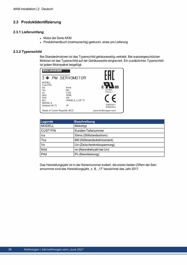
2.3.2 TypenschildBei Standardmotoren ist das Typenschild gehäuseseitig verklebt. Bei wassergeschütztenMotoren ist das Typenschild auf der Gehäuseseite eingraviert. Ein zusätzliches Typenschildist jedemMotorpaket beigefügt.
Legende BeschreibungMODELL MotortypCUST P/N Kunden-TeilenummerIcs I0rms (Stillstandsstrom)Tcs M0 (Stillstandsdrehmoment)Vs Un (Zwischenkreisspannung)Nrtd nn (Nenndrehzahl bei Un)Prtd Pn (Nennleistung)
Das Herstellungsjahr ist in der Seriennummer kodiert: die ersten beiden Ziffern der Seri-ennummer sind das Herstellungsjahr, z. B. „17“ bezeichnet das Jahr 2017.
38 Kollmorgen | kdn.kollmorgen.com | June 2021
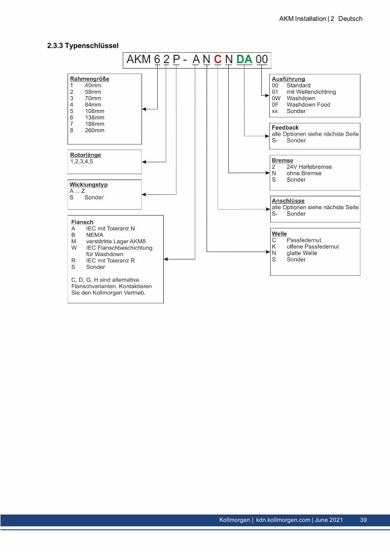
2.3.3 Typenschlüssel
AKM Installation | 2 Deutsch
Kollmorgen | kdn.kollmorgen.com | June 2021 39
AKM Installation | 2 Deutsch
2.3.3.1 Anschluss Optionen (C)Die Steckerbelegungen für Leistung und Feedback finden Sie ab ( # 209).Die technische Beschreibung der diversen Stecker finden Sie im Kollmorgen Developer Network(Gegenstecker).Anschluss Beschreibung
* Temperatursensor PTC oder KTY oder PT1000 ( # 45)** Bei Steckeroptionen D, R und U hängt die Art des Temperatursensors vom Feedbacktyp ab, siehe ( # 42)
2.3.3.2 Feedback Optionen (DA)DieMotorlänge hängt von der eingebauten Rückführeinheit (Feedback) ab, sieheMaßzeichnungen ab ( # 194).Ein nachträglicher Einbau ist nicht möglich. Die Steckerbelegungen für die Optionen finden Sie ab ( # 209).Die technische Beschreibung der diversen Feedback Systeme finden Sie im Kollmorgen Developer Network(Multi-Feedback).
Feedback Beschreibung
Code Bezeichnung Type Bemerkung Striche/Umdr.
AnzahlUmdr.
Verwendbarnur mit
1- Comcoder EPC 15T Single Turn, optisch 1024 1 Alle2- Comcoder EPC 15T Single Turn, optisch 2048 1 AlleAA BiSS B Encoder AD34/AD58 Single Turn, optisch 2048 1 AlleAB BiSS B Encoder AD34/AD58 Multi Turn, optisch 2048 4096 AlleC- SFD Size 10/15/21 Single Turn, induktiv, 4 adrig 11bit 1 AKDCA SFD3 Size 10/15/21 Single Turn, induktiv, 2 adrig 11bit 1 AKD,S700DA EnDAT 2.1 Encoder ECN1113/1313 Single Turn, optisch 512/2048* 1 AlleDB EnDAT 2.1 Encoder EQN1125/1325 Multi Turn, optisch 512/2048* 4096 AlleLA EnDAT 2.1 Encoder ECI1118/1319 Single Turn, induktiv 16/32** 1 AlleLB EnDAT 2.1 Encoder EQI1130/1331 Multi Turn, induktiv 16/32** 4096 AlleMA DRIVE-CLiQ Encoder ECN1324S Safety Single Turn, optisch 24bit 1 Siemens****MB DRIVE-CLiQ Encoder EQN1336S Safety Multi Turn, optisch 24bit 4096 Siemens****GA HIPERFACE Encoder SKS36 Single Turn, optisch 128 1 SxGB HIPERFACE Encoder SKM36 Multi Turn, optisch 128 4096 SxGC HIPERFACE Encoder SEK34 Single Turn, kapazitiv 16 1 SxGD HIPERFACE Encoder SEL34 Multi Turn, kapazitiv 16 4096 SxGE HIPERFACE DSL Encoder EKS36 Single Turn, optisch, 18bit 1 AKD,S700
GN Safe HIPERFACE Encoder SKM36S Safety, wie GK, SIL2, PLd,Kat.3 128*** 4096 AKD
GP HIPERFACE Encoder SEK34 Single Turn, kapazitiv 16 1 AKDGR HIPERFACE Encoder SEL34 Multi Turn, kapazitiv 16 4096 AKD
R- Resolver Size 10/15/21 Single Turn, induktiv 2 polig 1 Alle außerAKD-N
* x/y Daten für AKM2-4/AKM5-8** x/y Daten für AKM2-3/AKM4-8*** Zertifikate für sichere Geber finden Sie im Kollmorgen Developer Network (Zulassungen) oder auf der KollmorgenWebsite.****Aus rechtlichen Gründen dürfen wir keinen Servoverstärker anbieten, der dieses Feedback unterstützt. Für detail-lierte Informationen kontaktieren Sie bitte unseren technischen Support.Kollmorgen bietet in Europa die Servoverstärker S200, S300, S400, S600, S700, AKD, AKD-N an.
5...+40 °C bei einer Aufstellhöhe bis 1000 m über NN.Sprechen Sie bei Umgebungstemperaturen über 40°C und beigekapseltem Einbau der Motoren unbedingt mit unserer Appli-kationsabteilung.
Zulässige Luft-feuchtigkeit(bei Nennwerten)
95 % relative Feuchtigkeit, nicht kondensierend
Leistungsreduzierung(Ströme und Dreh-momente)
1 %/K im Bereich 40 °C...50 °C bis 1000 m über NN.Bei Aufstellhöhen über 1000 m über NN und 40 °C6 % bei 2000 m über NN17 % bei 3000 m über NN30 % bei 4000 m über NN55 % bei 5000 m über NNKeine Leistungsreduzierung bei Aufstellhöhen über 1000 m überNN und Temperaturreduzierung um 10K/1000 m
Lebensdauer Kugellager ≥ 20.000 Betriebsstunden
Die technischen Daten für jedenMotortyp finden Sie im Kapitel „Technische Daten“ auf (# 173).
2.4.2 AusführungDie Grundbauform derMotorenAKM ist die Bauform IM B5nach DIN EN 60034-7.
2.4.3 FlanschIEC-Flanschgenauigkeit nach DIN 42955. Toleranzen des Wellenauslaufs und des Mon-tageflansches bei rotierenden elektrischenMaschinen.
Code FlanschA IEC mit Genauigkeit N, Passung AKM1: h7, Passung AKM2–8: j6R IEC mit Genauigkeit R, Passung AKM1: h7, Passung AKM2–8: j6M IEC mit Genauigkeit N, Passung j6, verstärktes Lager, AKMnur 8:W IEC, Passung j6, spezielle Flanschbeschichtung für wassergeschützte Motoren,
auch für die Lebensmittelindustrie.B NEMA, Abmessungen siehe „AKM Selection Guide“ (Webseite von Kollmorgen,
englischsprachig)
2.4.4 SchutzklasseStandardmotor Anschlussopton Wellendichtung SchutzklasseAKM1 C, D ohne IP40AKM1 C, D, Y mit IP65AKM2-AKM7 B, C, D, G, H, T ohne IP54AKM8 H, T ohne IP52AKM2-AKM8 B, C, D, G, H, T mit IP65
AKM Installation | 2 Deutsch
Kollmorgen | kdn.kollmorgen.com | June 2021 43
AKM Installation | 2 Deutsch
Standardmotor Anschlussopton Wellendichtung SchutzklasseAKM2-AKM6Washdown B, C, D, G mit IP67AKM2-AKM6Washdown lebens-mittel
B, C, D, G mit IP67
2.4.5 IsolierstoffklasseDieMotoren entsprechen der Isolierstoffklasse F nach IEC 60085 (UL1446 Klasse F).
2.4.6 OberflächeDieMotoren sind beschichtet mit: Polyester Pulverbeschichtung inmattschwarz. DieseBeschichtung ist nicht beständig gegen Lösungsmittel (z. B. Trichlorethylen, Nitroverdünnero. ä.).
2.4.7 Wellenende, A-SeiteDie Kraftübertragung erfolgt über das zylindrischeWellenende A, Passung k6 (AKM1: h7)nach DIN EN 50347mit Anzugsgewinde, jedoch ohne Passfedernut.Die Motoren sind auchmit Passfedernut und eingesetzter Passfeder nach DIN6885 erhält-lich. DieWuchtung derWelle mit Passfedernut erfolgt mit kurzer (halber) Passfeder.Für die Lebensdauer der Lager sind 20.000 Betriebsstunden zugrunde gelegt.
RadialkraftTreiben dieMotoren über Ritzel oder Zahnriemen an, so treten hohe Radialkräfte auf. DiezulässigenWerte amWellenende können den Diagrammen im Kapitel „Zeichnungen“ ent-nommenwerden ( # 194). DieMaximalwerte bei Nenndrehzahl finden Sie in den tech-nischen Daten auf ( # 173). Bei Kraftangriff an der Mitte des freienWellenendes kann FR10 % größer sein.
AxialkraftBei der Montage von Ritzeln oder Riemenscheiben an die Achse und der Verwendung vonz. B. Winkelgetrieben treten Axialkräfte auf. DieMaximalwerte bei Nenndrehzahl finden Siein den technischen Daten.
KupplungAls ideale spielfreie Kupplungselemente haben sich doppelkonische Spannzangen, eventuellin Verbindungmit Metallbalg-Kupplungen, bewährt.
2.4.8 WellendichtungWird AKM an einenMaschinenflanschmit nicht abgedichtetemWellenbereich ange-schlossen, so sorgt dieWellendichtung (Option „01“) für die Abdichtung derWelle.
l Die Teflon-Wellendichtung gewährleistet die Schutzart IP67 für denWellenbereich.l Die Nennleistung wird nach einigen Stunden des Einlaufens derWellendichtung erreicht.Ein spezieller Einlaufprozess ist nicht erforderlich.
l Ein leichtes „Ablösen“ des Teflonmaterials ist üblich und beeinträchtigt die Funktion nicht.l Der Betrieb derWellendichtung im Trockenlauf ist verboten. Wenn ein Trockenlauf erfor-derlich ist, wenden Sie sich bitte an Kollmorgen.
l DieWellendichtung ist mit einem Schmierfett gemäß den Vorgaben der FDA (US-ame-rikanische Lebensmittel- und Arzneimittelbehörde) vorgeschmiert.
44 Kollmorgen | kdn.kollmorgen.com | June 2021
2.4.9 SchutzeinrichtungIn der Standardausführung ist jeder Motor mit einem potentialfreien PTC Temperatursensorausgestattet. Der Schaltpunkt liegt bei 155°C ± 5%. Schutz gegen kurzzeitige, sehr hoheÜberlastung bietet der PTC nicht.Optional kann der Motor mit einem PT1000, KTY 84-110 Sensoren ausgerüstet werden(siehe Anschlussoption ( # 209)( # 40)Bei den digitalen Feedbacks SFD, SFD3, DSL (C-, CA, GE, GF) wird der Status des Tem-peratursensors digital übertragen und im Servoverstärker ausgewertet.Der Sensor ist bei Verwendung unserer konfektionierten Feedbackleitungen in das Über-wachungssystem der digitalen Servoverstärker integriert.
2.4.10 SchwingungsklasseDieMotoren sind in der Schwingungsklasse A nach DIN EN 60034-14 ausgeführt. Dasbedeutet bei einem Drehzahlbereich von 600–3600 U/min und einemWellenmittelpunkt zwi-schen 56–132 mm beträgt der tatsächlicheWert der zulässigen Schwingstärke 1,6 mm/s.
2.4.11 Vibrationen and SchocksVibration nach norm EN 60068-2-6 : 2007:
Vibrationen 10G / 10-2000Hz
Schocks nach norm EN 60068-2-27 : 2008:
Schocks 100G / 6ms
2.4.12 Anschlusstechnik
2.4.12.1 SteckerBeschreibungen der verfügbaren Stecker: ( # 39). Steckerbelegung: von ( # 209).
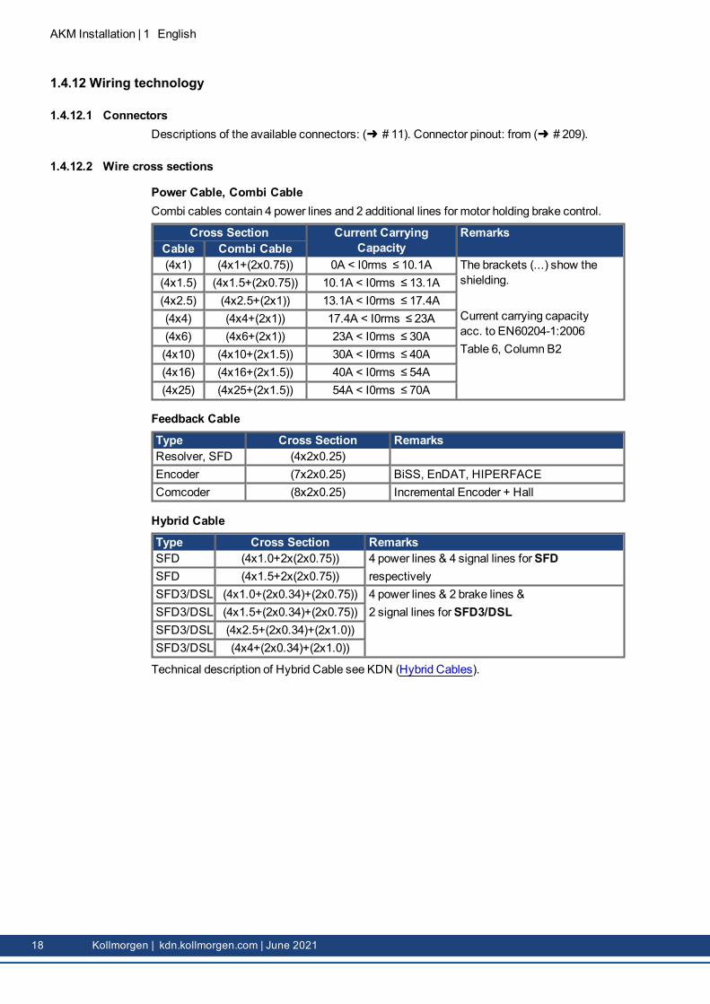
2.4.12.2 Leitungsquerschnitte
Leistungsleitungen, KombikabelKombikabel enthalten 4 Leistungsleitungen und 2 zusätzliche Leitungen zur Steuerung derMotorhaltebremse.
Querschnitt Strombelastbarkeit BemerkungKabel Kombikabel(4 x 1) (4 x 1 + (2 x 0,75)) 0 A < I0rms ≤ 10,1 A Die Klammern (....) kennzeichnen die Abschirmung.
Strombelastbarkeit nach DIN EN 60204-1:2006Tabelle 6, Spalte B2
(4 x 1,5) (4 x 1,5 + (2 x 0,75)) 10,1 A < I0rms ≤ 13,1 A(4 x 2,5) (4 x 2,5 + (2 x 1)) 13,1 A < I0rms ≤ 17,4 A(4 x 4) (4 x 4 + (2 x 1)) 17,4 A < I0rms ≤ 23 A(4 x 6) (4 x 6 + (2 x 1)) 23 A < I0rms ≤ 30 A(4 x 10) (4 x 10 + (2 x 1,5)) 30 A < I0rms ≤ 40 A(4 x 16) (4 x 16 + (2 x 1,5)) 40 A < I0rms ≤ 54 A(4 x 25) (4 x 25 + (2 x 1,5)) 54 A < I0rms ≤ 70 A
AKM Installation | 2 Deutsch
Kollmorgen | kdn.kollmorgen.com | June 2021 45
AKM Installation | 2 Deutsch
Rückführkabel
Typ Querschnitt BemerkungResolver, SFD (4 x 2 x 0,25)Encoder (7 x 2 x 0,25) BiSS, EnDAT, HIPERFACEComCoder (8 x 2 x 0,25) Inkrementalgeber + Hall
46 Kollmorgen | kdn.kollmorgen.com | June 2021
Hybridkabel
Typ Querschnitt BemerkungSFD (4 x 1,0 + 2 x (2 x 0,75)) 4 Leistungsleitungen und 4 Signalleitungen fürSFD
bzw.SFD (4 x 1,5 + 2 x (2 x 0,75))SFD3/DSL (4 x 1,0 + (2 x 0,34) +
(2 x 0,75))4 Leistungsleitungen, 2 Bremsleitungen und2 Signalleitungen fürSFD3/DSL
SFD3/DSL (4 x 1,5 + (2 x 0,34) + (2 x 0,75))
SFD3/DSL (4 x 2,5 + (2 x 0,34) + (2 x 1,0))
SFD3/DSL (4 x 4 + (2 x 0,34) + (2 x 1,0))
Für eine technische Beschreibung des Hybridkabels siehe KDN (Hybridkabel).
2.4.13 HaltebremseSämtlicheMotoren sind wahlweisemit eingebauter Haltbremse erhältlich. Eine Feder-kraftbremse (24 VDC) ist in die Motoren integriert. Wird diese Bremse nicht mit Strom ver-sorgt, so blockiert sie den Rotor.
WARNUNG Hängende Lasten sichern!
Bei hängenden Lasten (Vertikalachsen) wird die Haltebremse des Motors gelöst und gleich-zeitig erzeugt der Servoverstärker keine Leistung – die Last kann herunterfallen! Es bestehtVerletzungsgefahr für das Personal, dass dieMaschine bedient.
l Für die Funktionssicherheit bei hängenden Lasten (Vertikalachsen) müssen sicher-heitstechnischeMaßnahmen entsprechend den gültigen Normen angewendet werden.
Die Haltebremsen sind als Stillstandsbremsen ausgelegt und für betriebsmäßige Abbrems-vorgänge ungeeignet. Bei häufigem, betriebsmäßigem Bremsenmuss mit vorzeitigem Ver-schleiß und Ausfall der Haltebremse gerechnet werden.
Der Motor verlängert sich bei eingebauter Haltebremse.Die Haltebremse kann direkt vom Servoverstärker angesteuert werden (keine Per-sonensicherheit!), dann erfolgt das Löschen der Bremswicklung im Servoverstärker – einezusätzliche Beschaltung ist nicht erforderlich (siehe Betriebsanleitung des Ser-voverstärkers). Wird die Haltebremse nicht direkt vom Servoverstärker angesteuert, musseine zusätzliche Beschaltung (z. B. Varistor) vorgenommenwerden. Wenden Sie sich hierzubitte an unsere Kundendienstabteilung.Die Bremsendaten sind im Kapitel „Technische Daten der Bremsen“ ab ( # 191) aufgeführt.
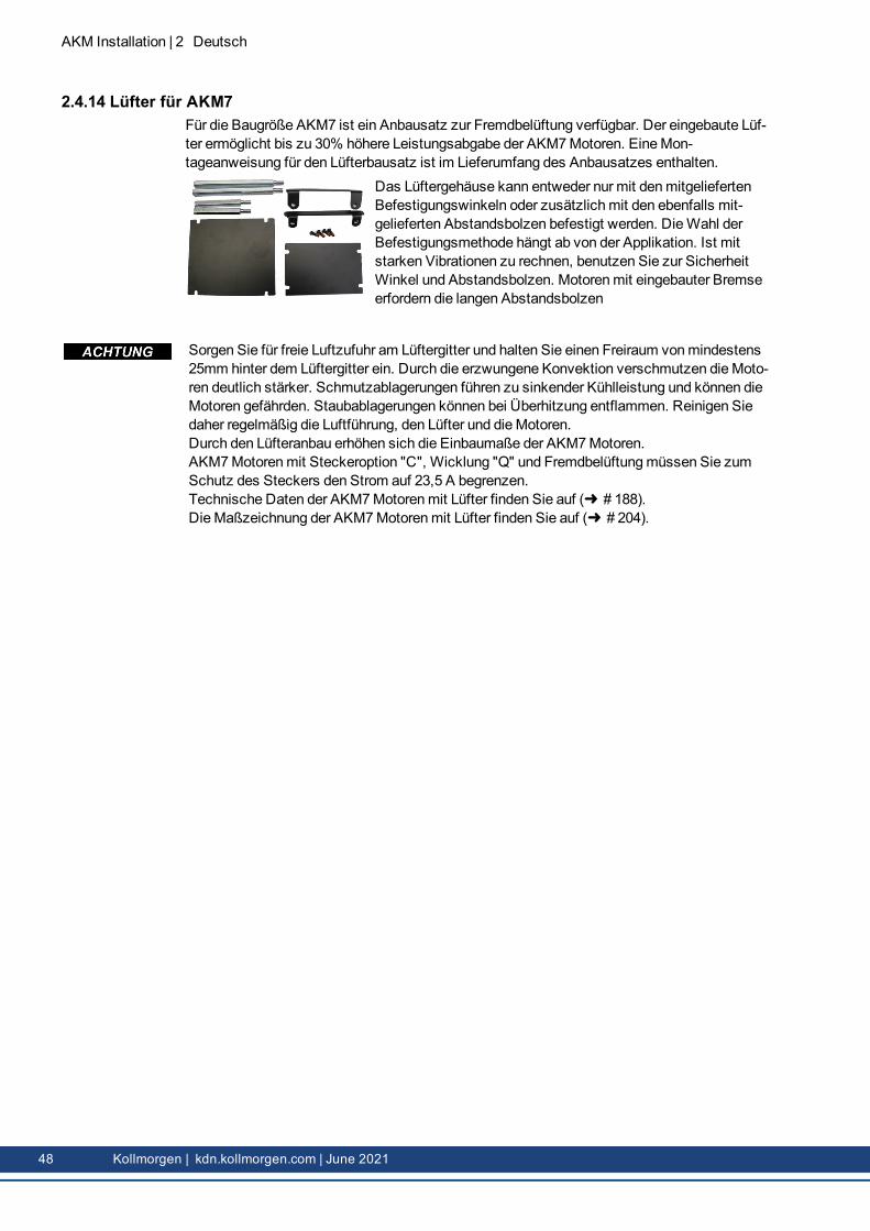
2.4.14 Lüfter für AKM7Für die Baugröße AKM7 ist ein Anbausatz zur Fremdbelüftung verfügbar. Der eingebaute Lüf-ter ermöglicht bis zu 30% höhere Leistungsabgabe der AKM7Motoren. EineMon-tageanweisung für den Lüfterbausatz ist im Lieferumfang des Anbausatzes enthalten.
Das Lüftergehäuse kann entweder nur mit denmitgeliefertenBefestigungswinkeln oder zusätzlichmit den ebenfalls mit-gelieferten Abstandsbolzen befestigt werden. DieWahl derBefestigungsmethode hängt ab von der Applikation. Ist mitstarken Vibrationen zu rechnen, benutzen Sie zur SicherheitWinkel und Abstandsbolzen. Motorenmit eingebauter Bremseerfordern die langen Abstandsbolzen
Sorgen Sie für freie Luftzufuhr am Lüftergitter und halten Sie einen Freiraum vonmindestens25mm hinter dem Lüftergitter ein. Durch die erzwungene Konvektion verschmutzen dieMoto-ren deutlich stärker. Schmutzablagerungen führen zu sinkender Kühlleistung und können dieMotoren gefährden. Staubablagerungen können bei Überhitzung entflammen. Reinigen Siedaher regelmäßig die Luftführung, den Lüfter und dieMotoren.Durch den Lüfteranbau erhöhen sich die Einbaumaße der AKM7Motoren.AKM7Motorenmit Steckeroption "C", Wicklung "Q" und Fremdbelüftungmüssen Sie zumSchutz des Steckers den Strom auf 23,5 A begrenzen.Technische Daten der AKM7Motorenmit Lüfter finden Sie auf ( # 188).DieMaßzeichnung der AKM7Motorenmit Lüfter finden Sie auf ( # 204).
48 Kollmorgen | kdn.kollmorgen.com | June 2021
2.4.15 Washdown und Washdown FoodDieseMotorvarianten werden in Applikationen eingesetzt, die strengen hygienischen Vor-schriften unterliegen, in denen es Keimbildung und Korrosion zu vermeiden gilt und in denenMaschinen zyklisch gereinigt werdenmüssen.DieMotoren basieren auf den Standardtypen AKM2 - AKM6mit speziellen Veränderungenfür den Einsatz in der Lebensmittel verarbeitenden Industrie oder auch in der Ver-packungsindustrie. Zusätzlich gibt es jeweils die Möglichkeit, auch den Flansch zu beschich-ten - dann kann die Toleranzklasse N für den Flansch allerdings nicht gewährleistet werden.Im Typenschlüssel ist die Lackierung des Motorgehäuses (Typen "W" fürWashdown, "F" fürWashdown Food) in der Ausführung (letzten zwei Stellen) und die Flanschbeschichtunggetrennt definiert.
Washdown Food Lackierung ohne FlanschbeschichtungWashdown Foodmit Flanschbeschichtung des IEC A-Flansch
Die Oberfläche des Washdown FoodMotoren hat alle Tests gemäß FDA GlobalMigration fürindirekten Kontakt zu Lebensmitteln bestanden. Ein direkter Kontakt zu unverpacktenLebensmitteln ist nicht zulässig.
Einsatzgebiet: Lebensmittel- undGetränkeindustrie, kein direkter Kontakt mit unver-packten Lebensmitteln
Beispiel: Schneiden, Verpacken und Füllen ohne direkten Kontakt zum Lebens-mittel, Motor seitlich oder unter dem Lebensmittel.
Standards: UL, CE, RohS, FDAOberfläche: Weiße BeschichtungBeständigkeit: Gegen geprüfte Reinigungsmittel ( # 50), korrosionsfestGlobal Migration: US FDA Regulations 21 CFR 175.300, Condition of Use ESchutzart: IP67Welle: EdelstahlWellendichtring: PTFE, gemäß FDASchmiermittel: Lebensmitteltauglich, gemäß FDAStecker: Edelstahl, glatte OberflächeSchrauben: EdelstahlTypenschild: Eingraviert, je Verpackungseinheit ein zusätzliches TypenschildBaugröße: AKM2 - AKM6
2.4.15.3 Geprüfte und bestätigte Eigenschaften gegenüber ReingungsmittelIm Prüflabor der ECOLAB DeutschlandGmbH wurde die Resistenz derWashdown undWas-hdown FoodOberflächen gegen folgende industrielle Reinigungsmittel geprüft:
l P3-topactive DESl P3-topactive LAl P3-topax 56l P3-topax 66l P3-topax 91Dabei wurden die Oberflächen 28 Tage lang bei Raumtemperatur in das jeweilige Rei-nigungsmittel getaucht.Dies entspricht ca. 2500 Reingungszyklenmit jeweils 15minütigem Kontakt zum Rei-nigungsmittel bzw. 1500 Reinigungszyklenmit Reinigung und nachfolgender Desinfektion.Die Zertifikate finden Sie in unserem Kollmorgen Developer Network auf der Seite Zulas-sungen .
Kollmorgen kann eine Gewährleistung der Motorlebensdauer nur bei Einsatz der getestetenReinigungsmittel geben. Andere als die oben genannten Reinigungsmittel kann Kollmorgenauf Anfrage testen und gegebenfalls freigeben.
l DieMotoren dürfen nur bei Umgebungstemperaturen bis maximal 50°C eingesetzt wer-den.
l Bei beschichtetem Vorderflansch ist die Toleranzklasse N nicht gewährleistet.
Bei Motorenmit Flanschen ohneWashdown Beschichtungmuss die Flanschfläche durchgeeigneteMontage vor dem Einfluss von Reinigungsmitteln geschützt werden.Bei Montage und Betrieb schützen Sie denMotor vor mechanischen Einwirkungen, die Krat-zer oder Risse auf der lackierten Oberfläche verursachen können. Das Fehlverhalten erhöhtdas Korrosionsrisiko.
2.4.15.5 ReinigungsplanEmpfohlener Reinigungsplan (Kurzform)mit den getesteten Reinigungsmitteln:
Spülen mit Wasser (40 °... 50 °C)Spülenmit niedrigem Druck. Von oben nach unten in Richtung zum Abfluss. Den Abfluss rei-nigen.
SchaumreinigungSchäumen von oben nach unten.Alkalisch: P3-topactive LA oder P3-topax 66 (2-5%, täglich 15min)Sauer: P3-topax 56 (2%, wenn erforderlich 15min)Temperatur: kalt bis zu 40 °C
DesinfektionAbsprühenmit Wasser (40°... 50°C)mit niedrigem Druck. Von oben nach unten.Sprühdesinfektion: P3-topax 91 (1-2%, wenn erforderlich 30-60min)Schaumdesinfektion: P3-topactiv DES (1-3%, wenn erforderlich 10-30min)
AKM Installation | 2 Deutsch
Kollmorgen | kdn.kollmorgen.com | June 2021 51
AKM Installation | 2 Deutsch
2.5 Mechanische InstallationMaßzeichnungen finden Sie im Kapitel „Maßzeichnungen“( # 194).
l Schützen Sie denMotor vor unzulässiger Beanspruchung. Bei Transport und Handhabungdürfen keine Bauteile beschädigt werden.
l Der Einbauort muss frei von leitfähigen und aggressiven Stoffen sein. Beachten Sie beider V3-Montage (Wellenende nach oben), dass keine Flüssigkeit in die Lager eindringendarf. Wird eine gekapselte Baugruppe benötigt, so wenden Sie sich bitte vorab an Koll-morgen.
l Stellen Sie die ungehinderte Belüftung der Motoren sicher und beachten Sie die zulässigeUmgebungs- und Flanschtemperatur. Bei Umgebungstemperaturen über 40 °C wendenSie sich bitte zunächst an unsere Applikationsabteilung. Sorgen Sie für eine ausreichendeWärmeübertragung in der Umgebung und amMotorflansch.
l DerMotorflansch und dieWelle sind bei Lagerung und Einbau besonders gefährdet – ver-meiden Sie daher rohe Kraftanwendung. Verwenden Sie zum Anziehen von Kupplungen,Zahnrädern oder Riemenscheiben unbedingt das vorgesehene Anzugsgewinde und erwär-men Sie, sofernmöglich, die Antriebskomponenten. Schläge oder Gewaltanwendung füh-ren zur Beschädigung der Lager und derWelle.
l Verwenden Sie nachMöglichkeit nur spielfreie, reibschlüssige Spannzangen oder Kupp-lungen. Achten Sie auf korrektes Ausrichten der Kupplung. Ein Versatz führt zu unzu-lässigen Vibrationen und zur Zerstörung der Lager und der Kupplung.
l Vermeiden Sie unter allen Umständen einemechanisch überbestimmte Lagerung derMotorwelle durch eine starre Kupplungmit externe Zusatzlagerung (z. B. im Getriebe).
l Beachten Sie dieMotorpolzahl und gegebenenfalls die Resolverpolzahl und stellen Sie beiden verwendeten Servoverstärkern die Polzahlen unbedingt korrekt ein. Eine falsche Ein-stellung kann insbesondere bei kleinenMotoren zur Zerstörung des Motors führen.
l Vermeiden Siemöglichst eine axiale Belastung der Motorwelle. Eine axiale Belastung ver-kürzt die Lebensdauer des Motors erheblich.
l Prüfen Sie die Einhaltung der zulässigen Radial- und Axialbelastungen FR und FA. Bei Ver-wendung eines Zahnriemen-Antriebs ergibt sich der minimal zulässige Durchmesser desRitzelsz. B. nach der Gleichung: dmin ≥ (M0/FR) x 2
52 Kollmorgen | kdn.kollmorgen.com | June 2021
2.6 Elektrische InstallationDie Belegung des Steckers finden Sie im Kapitel „Steckerbelegung“ von ( # 209). Die Bele-gung des Servoverstärkerendes finden Sie in der Betriebsanleitung des Servoverstärkers.
2.6.1 Wichtige HinweiseNur Fachleutemit elektrotechnischer Ausbildung dürfen denMotor verdrahten.GefährlicheSpannung!
GEFAHR Gefährliche Spannung!
Montieren und verdrahten Sie dieMotoren immer im spannungsfreien Zustand, d. h. keineder Betriebsspannungen eines anzuschließendenGerätes darf eingeschaltet sein.Es besteht die Gefahr von Tod oder schweren Verletzungen durch Berühren freiliegenderKontakte. Achten Sie darauf, dass der Schaltschrank ausgeschaltet bleibt (Schranke, Warn-schilder usw.). Erst bei der Inbetriebnahmewerden die einzelnen Spannungen ein-geschaltet.Lösen Sie die elektrischen Verbindungen des Motors niemals unter Spannung. Es bestehtdie Gefahr eines elektrischen Schlages! Unter ungünstigen Umständen können Lichtbögenentstehen, die Personen verletzen und Kontakte beschädigen.Eine gefährliche Spannung, die durch Restladung entsteht, kann bis zu 10Minuten nachAbschalten der Netzspannung an den Kondensatoren anliegen. Steuer- und Leis-tungsanschlüsse können auch bei nicht drehendemMotor unter Spannung stehen.
l Messen Sie zur Sicherheit die Zwischenkreisspannung und warten Sie, bis diese unter60 V abgesunken ist.
Das Masse-Zeichen , das in allen Schaltplänen enthalten ist, gibt an, dass Sie für einemöglichst großflächige, elektrisch leitende Verbindung zwischen dem gekennzeichnetenGerät und der Montageplatte in Ihrem Schaltschrank sorgenmüssen. Diese Verbindungdient zur Unterdrückung von HF-Störungen und darf nicht verwechselt werdenmit dem PE-Zeichen (Schutzmaßnahme nach DIN EN 60204).
Verwenden Sie zur Verdrahtung des Motors die Anschlusspläne in der Installation-/In-betriebnahmeanweisung des verwendeten Servoverstärkers.
AKM Installation | 2 Deutsch
Kollmorgen | kdn.kollmorgen.com | June 2021 53
AKM Installation | 2 Deutsch
2.6.2 Leitfaden für die elektrische Installationl Überprüfen Sie, ob Servoverstärker undMotor zueinander passen. Vergleichen Sie dieNennspannung und den Nennstrom der Geräte. Führen Sie die Verdrahtung gemäß demAnschlussplan in der Betriebsanleitung des Servoverstärkers durch. Die Anschlüsse desMotors sind im Kapitel „Steckerbelegung“ ab ( # 194)dargestellt.
l Verlegen Sie sämtliche starkstromführenden Leitungen in ausreichendemQuerschnittnach DIN EN 60204. Die empfohlenenQuerschnitte finden Sie in den technischen Daten.
Abhängig vom Typ des verwendeten Servoverstärkers muss bei langenMotorleitung (>25 m) eineMotordrossel (3YL oder 3YLN) in die Motorleitung geschaltet werden (sieheBetriebsanleitung des Servoverstärkers und Zubehörhandbuch).
l Achten Sie auf einwandfreie Erdung von Servoverstärker undMotor. Verwenden Sie diekorrekte Erdung und EMV-Abschirmung gemäß der Betriebsanleitung des verwendetenServoverstärkers. Erden Sie dieMontageplatte und das Motorgehäuse.
l Bei Verwendung eines Motorleistungskabels mit integrierten Bremssteueradernmüssendie Bremssteueradern abgeschirmt sein. Die Abschirmungmuss beidseitig aufgelegt wer-den (siehe Betriebsanleitung des Servoverstärkers).
l Verkabelung:o Leistungs- und Steuerleitungenmöglichst getrennt voneinander verlegeno Rückführsystem anschließeno Motorkabel anschließen, Motordrosseln (falls vorhanden) in der Nähe des Verstärkers
montiereno Abschirmungen beidseitig auf Schirmklemmen bzw. EMV-Stecker auflegeno Haltebremse anschließen, falls vorhandeno Abschirmung an beiden Enden auflegen
l Legen Sie Abschirmungen großflächig (niederohmig) über metallisierte Steckergehäusebzw. EMV-gerechte Kabelverschraubungen auf.
l Anforderungen an das LeitungsmaterialKapazitätMotorleitung: kleiner als 150 pF/mResolverleitung: kleiner als 120 pF/m
2.6.3 Anschluss der Motoren mit vorkonfektionierten Leitungenl Führen Sie die Verdrahtung gemäß den geltenden Normen und Vorschriften durch.l Verwenden Sie für die Leistungs- und Resolverleitungen ausschließlich vorkonfektionierteund abgeschirmte Leitungen von Kollmorgen.
l Nicht korrekt aufgelegte Abschirmungen führen unweigerlich zu EMV-Störungen und beein-trächtigt die Funktion des Systems.
l Diemaximale Leitungslänge ist im Betriebsanleitung des verwendeten Servoverstäkersdefiniert.
Eine detaillierte Beschreibung der konfigurierten Leitungen entnehmen Sie bitte dem regio-nalen Zubehörhandbuch.
54 Kollmorgen | kdn.kollmorgen.com | June 2021
2.7 Inbetriebnahme
2.7.1 Wichtige HinweiseNur Fachleutemit weitreichenden Kenntnissen in den Bereichen Elek-trotechnik/Antriebstechnik dürfen die Antriebseinheit von Servoverstärker undMotor inBetrieb nehmen.
ACHTUNG Heiße Oberfläche!
Die Oberflächentemperatur des Motors kann im Betrieb 100 °C überschreiten.
l Es besteht Verbrennungsgefahr! Prüfen (messen) Sie die Temperatur des Motors.l Warten Sie, bis der Motor unter 40 °C abgekühlt ist, bevor Sie ihn berühren.
GEFAHR Hochspannungen!
Es können lebensgefährliche Spannungen bis zu 900 V auftreten. Es besteht die Gefahreines elektrischen Schlages! Prüfen Sie, ob alle unter Spannung stehenden Anschluss-punkte gegen unbeabsichtigtes Berühren gesichert sind.Lösen Sie die elektrischen Verbindungen des Motors niemals unter Spannung. Es bestehtdie Gefahr eines elektrischen Schlages! Die Restladung in den Kondensatoren des Antriebskann bis zu 10Minuten nach Abschalten der Netzspannung gefährlicheWerte aufweisen.Steuer- und Leistungsanschlüsse können auch bei nicht drehendemMotor unter Spannungstehen.
l Messen Sie zur Sicherheit die Zwischenkreisspannung und warten Sie, bis diese unter60 V abgesunken ist.
ACHTUNG Sichere ungeplante Bewegungen!
Es kann nicht ausgeschlossen werden, dass der Antrieb während der Inbetriebnahme unvor-hergesehene Bewegungen ausführt.
l Stellen Sie sicher, dass auch bei unbeabsichtigter Bewegung des Antriebes keineGefährdung für Personen oder Maschinen entstehen kann.
l DieMaßnahmen, die Sie in diesem Zusammenhang für Ihre Tätigkeit ergreifenmüssen,basieren auf der Risikobewertung der Anwendung.
AKM Installation | 2 Deutsch
Kollmorgen | kdn.kollmorgen.com | June 2021 55
AKM Installation | 2 Deutsch
2.7.2 Leitfaden für die InbetriebnahmeDie Vorgehensweise für die Inbetriebnahmewird als beispielhaft beschrieben. Je nach Ein-satz der Geräte kann eine andere Vorgehensweise sinnvoll oder notwendig sein.
1. Überprüfen Sie dieMontage und Ausrichtung des Motors.2. Überprüfen Sie die Antriebskomponenten (Kupplung, Getriebe, Riemenscheibe) auf festen
Sitz und korrekte Einstellung (zulässige Radial- und Axialkräfte beachten).3. Überprüfen Sie die Verdrahtung und Verbindungen zumMotor und zum Servoverstärker.
Achten Sie auf ordnungsgemäße Erdung.4. Überprüfen Sie die Funktion der Haltebremse, sofern vorhanden (24 V anlegen, Bremse
muss gelöst sein).5. Überprüfen Sie, ob sich der Rotor des Motors frei dreht (eventuell vorhandene Bremse
lösen). Achten Sie auf Schleifgeräusche.6. Überprüfen Sie, ob alle erforderlichenMaßnahmen gegen unbeabsichtigtes Berühren span-
nungsführender und beweglicher Teile getroffen wurden.7. Führen Sie weitere für Ihre Anlage spezifischen und notwendigen Prüfungen durch.8. Nehmen Sie nun, entsprechend der Inbetriebnahmeanweisung des Servoverstärkers, den
Antrieb in Betrieb.9. Nehmen Sie bei Mehrachssystemen jede Antriebseinheit (Servoverstärker undMotor) ein-
zeln in Betrieb.
56 Kollmorgen | kdn.kollmorgen.com | June 2021
2.7.3 Beseitigen von StörungenDie folgende Tabelle ist als „Erste Hilfe“-Kasten zu verstehen. Abhängig von den Bedin-gungen in Ihrem System können vielfältige Ursachen für die auftretende Störung ver-antwortlich sein. Nachfolgend werden vorwiegend die Fehlerursachen beschrieben, die denMotor direkt betreffen Auftretende Auffälligkeiten im Regelverhalten habenmeist ihre Ursa-che in fehlerhafter Parametrierung des Servoverstärkers. Die Dokumentation des Ser-voverstärkers und der Inbetriebnahmesoftware gibt darüber Auskunft.Bei Mehrachssystemen können weitere versteckte Fehlerursachen auftreten.
Fehler Mögliche Ursache Maßnahmen zur Beseitigung des FehlersMotor drehtnicht
– Servoverstärker nicht freigegeben– Sollwertleitung unterbrochen–Motorphasen vertauscht– Bremse ist nicht gelöst– Antrieb ist mechanisch blockiert
– Kurzschluss in der Span-nungszuleitungzur Motorhaltebremse– DefekteMotorhaltebremse
– Kurzschluss beseitigen
–Motor austauschen
Fehlermeldung:Endstufenfehler
–Motorleitung hat einen Kurz-/Erd-schluss–Motor hat einen Kurz- oder Erd-schluss
– Kabel austauschen–Motor austauschen
Fehlermeldung:Resolver
– Resolverstecker ist nicht richtigeingesteckt– Resolverleitung ist unterbrochen, Lei-tunggequetscht o.ä.
– Steckverbindung überprüfen
– Leitungen überprüfen
Fehlermeldung:Motortemperatur
–Motor-Thermosensor hat ange-sprochen
– Resolverstecker lose oder Resol-verleitung unterbrochen
– Abwarten bis Motor abgekühlt ist. Danach über-prüfen, warum derMotor so heiß wird.– Stecker prüfen, eventuell Resolverleitung aus-tauschen
Bremse greiftnicht
– Gefordertes Haltemoment zu hoch– Bremse defekt–Motorwelle axial überlastet
– Auslegung überprüfen–Motor austauschen– Axialbelastung überprüfen und reduzieren. Motoraustauschen, da die Lager beschädigt sind.
AKM Installation | 2 Deutsch
Kollmorgen | kdn.kollmorgen.com | June 2021 57
AKM Installation | 2 Deutsch
2.8 Begriffsdefinitionen für technische DatenDie technischen Daten für jedenMotortyp finden Sie im Kapitel „Technische Daten“ auf (# 173).
Sämtliche Daten gelten für 40°C Umgebungstemperatur und 100 Kelvin Übertemperatur derWicklung. Die Nenndaten werden bei konstanter Temperatur des Adapterflansches von65 °C ermittelt. Die Daten können eine Toleranz von +/- 10 % aufweisen.
Stillstandsdrehmoment M0 [Nm]Das Stillstandsdrehmoment kann bei einer Drehzahl von 0<n<100 U/min und Nenn-Umge-bungsbedingungen unbegrenzt lange abgegeben werden.
Nenndrehmoment Mn [Nm]Das Nenndrehmoment wird abgegeben, wenn der Motor bei Nenndrehzahl Nennstrom auf-nimmt. Das Nenndrehmoment kann im Dauerbetrieb (S1) bei Nenndrehzahl unbegrenzt langeabgegeben werden.
Stillstandsstrom I0rms [A]Der Stillstandsstrom ist der Sinus-Effektiv-Stromwert den der Motor bei 0<n<100 U/min auf-nimmt, um das Stillstandsdrehmoment abgeben zu können.
Spitzenstrom (Impulsstrom) I0max [A]Der Spitzenstrom (Sinus-Effektivwert) entspricht dem Vielfachen des Nennstroms in Abhän-gigkeit von der Motorwicklung. Der Istwert wird durch den Spitzenstrom des verwendetenAntriebs bestimmt.
Drehmomentkonstante KTrms [Nm/A]Die Drehmomentkonstante gibt an, wie viel Drehmoment in Nm derMotor bei 1 A Sinus-Effektivstrom erzeugt. Es gilt M=I x KT (bis maximal I=2 x I0).
Spannungskonstante KErms [mV/min-1]
Die Spannungskonstante gibt die auf 1000 U/min bezogene induzierte Motor-EMK als Sinus-Effektivwert zwischen zwei Klemmen an. Gemessen bei 25 °C.
Rotorträgheitsmoment J [kgcm²]Die Konstante J ist ein Maß für das Beschleunigungsvermögen des Motors. Mit I0 ergibt sichz. B. die Beschleunigungszeit tb von 0 bis 3000 U/min zu:
mit M0 in Nm und J in kgcm²
Thermische Zeitkonstante tth [min]Die Konstante tth gibt die Erwärmungszeit des kaltenMotors bei Belastungmit I0 bis zumErreichen von 0,63 x 10⁵ Kelvin Übertemperatur an. Bei Belastungmit Spitzenstrom erfolgtdie Erwärmung in wesentlich kürzerer Zeit.
Lüftungsverzögerungszeit tBRH [ms]/Einfallverzögerungszeit tBRL [ms] der BremseDie Konstanten geben die Reaktionszeiten der Haltebremse bei Betriebmit Nennspannungam Servoverstärker an.
3.2 Sicurezza 613.2.1 Prestare attenzione a questo aspetto 613.2.2 Uso secondo le istruzioni 633.2.3 Uso vietato 633.2.4Maneggiamento 64
3.3 Imballaggio 663.3.1 Imballaggio per la consegna 663.3.2 Targhetta di omologazione 663.3.3 Codici dei modelli 67
3.4 Descrizione tecnica 723.4.1 Dati tecnici generali 723.4.2 Tipo 723.4.3 Flangia 723.4.4 Classe di protezione 733.4.5 Classe del materiale isolante 733.4.6 Superficie 733.4.7 Estremità azionamento, lato A 733.4.8 Guarnizione dell'albero 743.4.9 Dispositivo di protezione 743.4.10 Classe di vibrazione 743.4.11 Vibrazioni e urti 743.4.12 Tecnologia di cablaggio 753.4.13 Freno di stazionamento 763.4.14 Ventola per AKM7 763.4.15Washdown eWashdown Food 77
3.5 Installazione meccanica 803.5.1 Note importanti 80
3.6 Installazione elettrica 813.6.1 Note importanti 813.6.2 Guida all'installazione elettrica 823.6.3 Collegamento dei motori con cavi preassemblati 82
3.7 Configurazione 833.7.1 Note importanti 833.7.2 Guida alla configurazione 843.7.3 Risoluzione dei guasti 85
3.8 Definizione dei termini per i dati tecnici 86
AKM Installation | 3 Italiano
Kollmorgen | kdn.kollmorgen.com | June 2021 59
AKM Installation | 3 Italiano
3.1 Informazioni generali
3.1.1 Informazioni sul presente manualeIl presentemanuale descrive la serie di servomotori sincroni adjust in target (versione stan-dard). I motori sono utilizzati in sistemi di azionamento insieme ai servoamplificatori Koll-morgen. Si prega di leggere attentamente l'intera documentazione sul sistema, costituita daquanto segue:
l Manuale di istruzioni per il servoamplificatorel Manuale di comunicazione bus (ad es. CANopen o EtherCAT)l Guida in linea del software di configurazione dell'amplificatorel Manuale regionale accessoril Descrizione tecnica della serie di motori AKMUlteriori informazioni di base possono essere reperite sul Kollmorgen Developer Network,disponibile presso kdn.kollmorgen.com.
3.1.2 Abbreviazioni usateLe abbreviazioni utilizzate per i dati tecnici sono reperibili nel capitolo "Definizione dei ter-mini" ( # 86).Nel presente documento il simbolo ( # 53) significa: vedere pagina 53.
3.1.3 Simboli usatiSimbolo Indicazione
PERICOLOIndica una situazione pericolosa che, se non evitata, pro-vocamorte o lesioni gravi.
AVVISOIndica una situazione pericolosa che, se non evitata, pro-vocamorte o lesioni gravi.
ATTENZIONEIndica una situazione pericolosa che, se non evitata, pro-voca lesioni non gravi o moderate.
Questo non è un simbolo di sicurezza.Questo simbolo indica una situazione pericolosa che, senon evitata, provoca danni materiali.
Questo non è un simbolo di sicurezza.Questo simbolo indica note importanti.
Avviso di pericolo (generale). Il tipo di pericolo è specificatonel testo a fianco.
Avviso di pericolo dovuto all'elettricità e ai suoi effetti.
Avviso di pericolo per la presenza di superfici calde.
3.2 SicurezzaQuesta sezione aiuta l'utilizzatore a riconoscere e a evitare i pericoli per le persone e glioggetti.
3.2.1 Prestare attenzione a questo aspetto
Affidare queste operazioni esclusivamente a personale specializzato!Attività quali il trasporto, l'installazione, la configurazione e lamanutenzione possono essereeseguite unicamente da personale debitamente qualificato. Con personale qualificato e spe-cializzato si intende il personale che ha dimestichezza con le fasi di trasporto, installazione,montaggio, messa in servizio e funzionamento dei motori e che utilizza le qualifiche di cuidispone per svolgere le rispettivemansioni:
l Trasporto: solo a cura di personale con nozioni di movimentazione componenti sensibilialle cariche elettrostatiche.
l Installazionemeccanica: solo a cura di meccanici qualificati.l Installazione elettrica: solo a cura di elettricisti qualificati.l Configurazione: solo a cura di personale qualificato esperto in elettrotecnica e nelle tec-nologie di azionamento
Il personale qualificato è tenuto a conoscere e a rispettare le norme IEC 60364/IEC 60664 ele norme antinfortunistiche nazionali.
Leggere la documentazione!Leggere la documentazione disponibile prima dell'installazione e della messa in funzione.Unamovimentazione inadeguata del motore può causare lesioni a persone o danni alla pro-prietà. L'operatore deve quindi garantire che tutte le persone incaricate di lavorare sul motoreabbiano letto e compreso il manuale e che vengano rispettate le avvertenze di sicurezza diquestomanuale.
Prestare attenzione ai dati tecnici!Attenersi ai dati tecnici e alle specifiche sulle condizioni di collegamento (targhetta e docu-mentazione). Se i valori di tensione o di corrente accettabili vengono superati, i motori pos-sono risultare danneggiati, ad esempio a causa del surriscaldamento.
Eseguire un'analisi dei rischi!Il produttore della macchina deve produrre un'analisi dei rischi relativa alla macchina ed adot-taremisure adeguate per assicurare che eventuali movimenti imprevisti non possano cau-sare lesioni o danni a persone o cose. Requisiti aggiuntivi per il personale specializzatopossono anche risultare dalla valutazione dei rischi.
Eseguire il trasporto in sicurezza!Sollevare e spostaremotori di oltre 20 kg di peso (AKM7 e AKM8) solo con appositi attrezziper il sollevamento. Operazioni di sollevamento eseguite senza ricorrere a tali attrezzi potreb-bero provocare lesioni alla schiena. Rispettare sempre i suggerimenti su ( # 64)
Fissare la chiave!Rimuovere qualsiasi chiave installata dall'albero (se presente) prima di azionare il motoresenza carico accoppiato per evitare il pericolo che la chiave venga espulsa dalle forze cen-trifughe. Quando viene consegnata, la chiave è protetta con un tappo di plastica.
AKM Installation | 3 Italiano
Kollmorgen | kdn.kollmorgen.com | June 2021 61
AKM Installation | 3 Italiano
ATTENZIONE Superficie calda!
Le superfici dei motori possono esseremolto calde durante il funzionamento, a secondadella loro categoria di protezione. Rischio di lievi ustioni! La temperatura della superficie puòsuperare 100 °C.
l Misurare la temperatura e attendere che la temperatura del motore scenda al di sotto di40 °C prima di toccarlo.
PERICOLO Messa a terra! Alta tensione!
È di vitale importanza garantire che l'alloggiamento del motore sia messo a terra in modosicuro alla barra di distribuzione PE (messa a terra di protezione) nell'armadio elettrico.Rischio di scosse elettriche. Senza unamessa a terra a bassa resistenza non può esseregarantita la protezione personale e sussiste un pericolo di morte per scosse elettriche.Lamancanza di visualizzazioni ottiche non garantisce l'assenza di tensione. I collegamentidi alimentazione possono portare tensione anche se l'alberomotore non ruota.
l Non scollegare i connettori durante il funzionamento. Toccare i contatti esposti comportaun pericolo di morte o di lesioni gravi. I collegamenti di alimentazione possono esseresotto tensione anche se l'alberomotore non ruota. Questo può causare fiammate conconseguenti lesioni alle persone e danni ai contatti.
l Dopo aver scollegato il servoamplificatore dalla tensione di alimentazione, attenderealcuni minuti prima di toccare i componenti normalmente sotto tensione (ad es. contatti,collegamenti a vite) o aprire eventuali collegamenti.
l I condensatori nel servoamplificatore possono ancora condurre una tensione pericolosadiversi minuti dopo l'interruzione delle tensioni di alimentazione. Per garantire la sicu-rezza, misurare la tensione DC-link o e attendere che la tensione sia scesa sotto i 60 V.
AVVERTENZA Fissare i carichi sospesi!
I freni di stazionamento incorporati non garantiscono la sicurezza funzionale!
l I carichi sospesi (assi verticali) richiedono un frenomeccanico esterno supplementareper garantire la sicurezza del personale.
62 Kollmorgen | kdn.kollmorgen.com | June 2021
3.2.2 Uso secondo le istruzionil La serie di servomotori sincroni AKM è progettata specialmente per azionamenti destinatia robot industriali, macchine utensili, macchinari tessili e d'imballaggio e simili con elevatirequisiti in termini di dinamica.
l All'utilizzatore è consentito azionare i motori solo nelle condizioni ambientali che sono defi-nite nella presente documentazione.
l L'uso di motoriWashdown è consentito in ambienti con basi e acidi caustici nel rispettodelle condizioni definite a pagina ( # 77).
l L'uso dei motoriWashdown Food è consentito in applicazioni che prevedono il contattoindiretto con alimenti e bevande.
l La serie di motori AKM è esclusivamente destinata a essere azionata da ser-voamplificatori in condizioni di controllo di velocità e/o coppia.
l I motori vengono installati come componenti in un apparecchio elettrico omacchine e pos-sono esseremessi in servizio e in funzione come parti integranti di tali apparecchi omac-chine.
l Il sensore termico integrato negli avvolgimenti del motore deve esseremonitorato e valu-tato.
l I freni di stazionamento sono progettati per lo stazionamento e non sono adatti per la fre-nata operativa ripetuta.
l La conformità del servosistema alle normemenzionate nella dichiarazione di conformitàCE ( # 216) è garantita solo quando i componenti utilizzati (servoamplificatore, motore,cavi, ecc.) sono stati forniti da Kollmorgen.
3.2.3 Uso vietatol L'uso dei motori standard è vietato
o direttamente su reti di alimentazione elettrica,o in aree in cui sussiste un rischio di esplosioni,o a contatto con alimenti e bevande,o in ambienti con basi, oli, vapori, polveri o acidi caustici e/o elettricamente conduttivi.
l L'uso dei motoriWashdown è vietatoo direttamente su reti di alimentazione elettrica,o in aree in cui sussiste un rischio di esplosioni,o a contatto con alimenti e bevande,o in ambienti con acidi o basi con un pH inferiore a 2 o superiore a 12,o in ambienti con acidi o basi che non sono stati testati da Kollmorgen.
l L'uso dei motoriWashdown Food è vietatoo direttamente su reti di alimentazione elettrica,o in aree in cui sussiste un rischio di esplosioni,o a contatto diretto con alimenti e bevande.
l Lamessa in funzione del motore è vietata se lamacchina in cui è stato installatoo non soddisfa i requisiti della DirettivaMacchine CE,o non è conforme alla direttiva sulla compatibilità elettromagnetica (EMC),o non è conforme alla Direttiva Bassa Tensione.
l Non utilizzare i freni di stazionamento incorporati senza ulteriori apparecchi per garantire lasicurezza funzionale.
AKM Installation | 3 Italiano
Kollmorgen | kdn.kollmorgen.com | June 2021 63
AKM Installation | 3 Italiano
3.2.4 Maneggiamento
3.2.4.1 Trasporto
l Classe climatica 2K3 secondo IEC 60721-3-2,EN61800-2l Temperatura :da -25 a +70°C, variazionemax. 20K/oral Umidità atmosferica:umidità relativa del 5% 95% senza condensal Solo da parte di personale qualificato in imballaggio originale riciclabile del produttorel Evitare urti violenti, in particolare sull'estremità dell'alberol In caso di imballaggio danneggiato, verificare che il motore non presenti danni visibili. Infor-marne il trasportatore ed eventualmente il produttore.
Trasporto di motori con un peso superiore a 20 kgGli anelli di sollevamento vengono utilizzati per trasportare i motori AKM7 e AKM8 (> 20 kg)in sicurezza.Rispettare le istruzioni di trasporto allegate alla confezione del motore. Suggeriamo l’attrezzoZPZM 120/292 di trasporto per lo spostamento dei motori.L’unità ZPMZ 120/292 della sospensione consiste di un fascio, sospeso al gancio della gru edue doppio-fanno funzionare le bretelle chain.
PERICOLO Carico sospeso!
Pericolo di morte in caso di caduta del carico. Quando si esegue la procedura di sol-levamento non sostaremai sotto il carico.
l Le viti di montaggio degli anelli di sollevamento devono essere serrate completamente.l Gli anelli di sollevamento devono essere posizionati sulla superficie di supporto in manierauniforme e in piano.
l Prima dell'utilizzo, verificare che gli anelli di sollevamento siano correttamentemontati eprivi di danni evidenti (corrosione, deformazione).
l Se si individuano delle deformazioni gli anelli di sollevamento non devono essere utilizzati.
64 Kollmorgen | kdn.kollmorgen.com | June 2021
3.2.4.2 Imballaggio
l Imballaggio del cartone con rivestimento di Instapak®.l Potete restituire la parte di plastica al fornitore (veda "Smaltimento")
l Classe climatica 1K4 secondo IEC 60721-3-1,EN61800-2l Temperatura di stoccaggio da -25 a +55°C, variazionemax. 20K/oral Umidità atmosfericaum. rel. del 5% 95% senza condensal Solo in imballaggio originale riciclabile del produttorel Per l'altezza d'impilaggio max. ved. tabella nella sezione "Imballaggio"l Durata amagazzinoillimitata
3.2.4.4 Manutenzione / Puliza
l Solo da parte di personale qualificatol Dopo 20.000 ore d'esercizio alle condizioni nominali occorre sostituire i cuscinetti a sfere.l Controllare il motore ogni 2500 ore d'esercizio o una volta l'anno per verificare la rumo-rosità dei cuscinetti a sfere. Se si riscontrano rumori evitare di utilizzare il motore i cusci-netti devono essere sostituiti.
l L'apertura dei motori comporta l'annullamento della garanzia.l Pulizia con isopropanolo o similari, non immergere o nebulizzare
3.2.4.5 Riparazioni / SmaltimentoIl motori può essere riparato unicamente dal fabbricante; l’apertura dell’apparecchio annullaautomaticamente la garanzia. Nell’accordo al WEEE-2012/19/EG-Guidelines prendiamo ivecchi dispositivi ed accessori indietro per eliminazione professionale, se i costi del tansportsono y rilevato il mittente. Trasmetta i dispositivi a:KOLLMORGEN s.r.o.Attn.: Repair DepartmentEvropska 864664 42ModriceCzech RepublicEmail: [email protected]: +420 533 314 455
AKM Installation | 3 Italiano
Kollmorgen | kdn.kollmorgen.com | June 2021 65
AKM Installation | 3 Italiano
3.3 Imballaggio
3.3.1 Imballaggio per la consegnal Motore della serie AKMl Manuale del prodotto (multi lingua) stampato, uno per ogni consegna
3.3.2 Targhetta di omologazioneNei motori standard la targhetta è adesiva sul lato involucro. Nei motori Washdown la tar-ghetta è incisa sul lato involucro, una targhetta supplementare è aggiunta ad ogni imballaggiodel motore.
Legenda DescrizioneMODEL tipo di motoreCUST P/N codice clienteIcs I0rms (corrente di arresto)Tcs M0 (coppia di arresto)Vs Un (tensione collegamento bus DC)Nrtd nn (velocità nominale a Un)Prtd Pn (potenza nominale)
L'anno di fabbricazione è codificato nel numero di serie: le prime due cifre del numero di serierappresentano l'anno di fabbricazione, ad es. "17" significa 2017.
66 Kollmorgen | kdn.kollmorgen.com | June 2021
3.3.3 Codici dei modelli
AKM Installation | 3 Italiano
Kollmorgen | kdn.kollmorgen.com | June 2021 67
AKM Installation | 3 Italiano
3.3.3.1 Opzioni di connettori (C)L'assegnazione dei connettori per le opzioni è descritta da ( # 209).Descrizione tecnica del connettori vedere Kollmorgen Developer Network (Mating Connectors).Descrizione di connessioni
Numero di poli Corrente max.[A]
Sezione max.[mm²] Grado di
protezioneConnettore di accop-piamento consigliatoConnettore Uso* Potenza/Segnale Potenza/Segnale Potenza/Segnale
* Sensore di temperatura PTC o KTY o PT1000 ( # 74)** Con l'opzione connettore D, R e U del tipo di sensore di temperatura dipende dal feedback, vedi ( # 71)
AKM Installation | 3 Italiano
Kollmorgen | kdn.kollmorgen.com | June 2021 69
AKM Installation | 3 Italiano
3.3.3.2 Unità di retroazione (DA)La lunghezza del motore dipende dall'unità di retroazionemontata, vedere i disegni quotati da ( # 194). Non èpossibile integrare l'unità in un secondo tempo. L'assegnazione dei connettori è descritta da ( # 209).Descrizione tecnica del feedback sistemi vedere Kollmorgen Developer Network (MultiFeedback).
Descrizione Feedback
Code Descrizione Tipo Commento Lignespar tour
Numerodi giri
Utilizzabilecon ampli-ficatori
1- Comcoder EPC 15T Single Turn, ottico 1024 1 tutto2- Comcoder EPC 15T Single Turn, ottico 2048 1 tuttoAA BiSS B Encoder AD34/AD58 Single Turn, ottico 2048 1 tuttoAB BiSS B Encoder AD34/AD58 Multi Turn, ottico 2048 4096 tuttoC- SFD, 4 lines Size 10/15/21 Single Turn, induttivo 11bit 1 AKDCA SFD3, 2 lines Size 10/15/21 Single Turn, induttivo 11bit 1 AKD,S700DA EnDAT 2.1 Encoder ECN1113/1313 Single Turn, ottico 512/2048* 1 tuttoDB EnDAT 2.1 Encoder EQN1125/1325 Multi Turn, ottico 512/2048* 4096 tuttoLA EnDAT 2.1 Encoder ECI1118/1319 Single Turn, induttivo 16/32** 1 tuttoLB EnDAT 2.1 Encoder EQI1130/1331 Multi Turn, induttivo 16/32** 4096 tuttoMA DRIVE-CLiQ Encoder ECN1324S Safety Single Turn, ottico 24bit 1 Siemens****MB DRIVE-CLiQ Encoder EQN1336S Safety Multi Turn, ottico 24bit 4096 Siemens****GA HIPERFACE Encoder SKS36 Single Turn, ottico 128 1 SxGB HIPERFACE Encoder SKM36 Multi Turn, ottico 128 4096 SxGC HIPERFACE Encoder SEK34 Single Turn, capacitivo 16 1 SxGD HIPERFACE Encoder SEL34 Multi Turn, capacitivo 16 4096 SxGE HIPERFACE DSL Encoder EKS36 Single Turn, ottico 18bit 1 AKD,S700
GN Safe HIPERFACE Enco-der SKM36S Safety, come GK, SIL2, PLd,
Cat.3 128*** 4096 AKD
GP HIPERFACE Encoder SEK34 Single Turn, capacitivo 16 1 AKDGR HIPERFACE Encoder SEL34 Multi Turn, capacitivo 16 4096 AKD
R- Resolver Size 10/15/21 Single Turn, induttivo 2 poli 1 Tutti tranneAKD-N
* x/y dati per AKM2-4/AKM5-8** x/y dati per AKM2-3/AKM4-8*** Certificati per "safety feedbacks": consultare Kollmorgen Developer Network (Approvals) o websiteKollmorgen.****Per motivi legali non siamo autorizzati a offrire alcuna guida che supporta questo dispositivo di feedback. Per infor-mazioni dettagliate si prega di contattare il nostro supporto tecnico.Tutti i servoamplificatori Kollmorgen offerti in Europa S200, S300, S400, S600, S700, AKD, AKD-N
* Nessun freno** Sensore di temperatura secondo le attuali esigenze di Siemens. Per ulteriori informazioni contattare Kollmorgen.
AKM Installation | 3 Italiano
Kollmorgen | kdn.kollmorgen.com | June 2021 71
AKM Installation | 3 Italiano
3.4 Descrizione tecnica
3.4.1 Dati tecnici generaliTemperatura ambiente(a valori nominali)
Da 5 a +40 °C per un'altitudine del sito fino a 1000mm slmÈ di importante consultare il nostro reparto di applicazioni pertemperature ambiente superiori a 40 °C e il montaggio incap-sulato dei motori.
Umidità ammessa(a valori nominali)
95% di umidità relativa, senza la formazione di condensa
Riduzione di potenza(correnti e coppie)
1%/K nell'intervallo da 40 °C a 50 °C fino a 1000mm slmper un'altitudine del sito superiore a 1000mm slm e 40 °C6% fino a 2.000m slm17% fino a 3000m slm30% fino a 4000m slm55% fino a 5000m slmNessuna riduzione della potenza per altitudini del sito oltre 1000m slm con riduzione della temperatura di 10K / 1000m
Durata dei cuscinetti asfera
≥ 20.000 ore di esercizio
I dati tecnici per ogni tipo di motore sono disponibili nel capitolo "Dati tecnici" da ( # 173).
3.4.2 TipoIl tipo di base per i motori AKMè IM B5 secondo EN 60034-7.
3.4.3 FlangiaPrecisione della flangia IEC secondo DIN 42955. Tolleranze di fuoriuscita dell'estensionedell'albero e di flange di montaggio per macchine elettriche rotanti.
Codice FlangiaA IEC con precisione N, montare AKM1: h7, montare AKM2-8: j6R IEC con precisione R, montare AKM1: h7, montare AKM2-8: j6M IEC con precisione N, montare j6, cuscinetto rinforzato, solo AKM8W IEC, montare j6, rivestimento speciale della flangia per motori Washdown oWash-
down FoodB NEMA, per le dimensioni vedereAKM Selection Guide (sito web Kollmorgen, in
inglese USA)
72 Kollmorgen | kdn.kollmorgen.com | June 2021
3.4.4 Classe di protezioneMotore standard Opzione con-
nettoreGuarnizione
alberoClasse di pro-
tezioneAKM1 C, D senza IP40AKM1 C, D, Y con IP65AKM2-AKM7 B, C, D, G, H, T senza IP54AKM8 H, T senza IP52AKM2-AKM8 B, C, D, G, H, T con IP65AKM2-AKM6Washdown B, C, D, G con IP67AKM2-AKM6WashdownFood
B, C, D, G con IP67
3.4.5 Classe del materiale isolanteI motori sono forniti fino alla classe del materiale isolante F secondo IEC 60085 (UL1446classe F).
3.4.6 SuperficieI motori sono rivestiti con rivestimento a polvere in resina epossidica nero opaco. Questa fini-tura non è resistente ai solventi (ad es. tricloroetilene, diluenti nitro o simili).
3.4.7 Estremità azionamento, lato ALa trasmissione di potenza è realizzata attraverso l'estremità dell'albero A, montare k6(AKM1: h7) secondo EN 50347 con filettatura di serraggio ma senza una sede della chia-vetta.I motori sono disponibili anche con la sede della chiavetta e la chiave inserita secondo DIN6885. L'albero con la sede della chiavetta è bilanciato con una chiavetta corta (metà).La durata dei cuscinetti è calcolata in 20.000 ore di esercizio.
Codice perordinazione
Estremità dell'albero Disponibile per
N Albero liscio tutti i tipi, standardC Sede della chiavetta, chiusa AKM 2...8K Sede chiavetta, aperta AKM 1...8
Forza radialeSe l'azionamento dei motori avviene tramite pignoni o cinghie dentate, si generano forzeradiali elevate. I valori ammissibili all'estremità dell'albero sono consultabili negli schemi nelcapitolo "Disegni" da ( # 194). I valori massimi alla velocità nominale sono disponibili neidati tecnici da ( # 173). La presa di forza dal centro dell'estremità libera dell'albero permetteun aumento del 10% in FR.
Forza assialeDurante il montaggio di pignoni o ruote all'asse e, ad esempio, l'uso di riduttori angolari, sigenerano forze assiali. . I valori massimi alla velocità nominale sono disponibili nei dati tec-nici.
AccoppiamentoGli anelli di serraggio a doppio cono si sono rivelati la soluzione ideale per dispositivi di accop-piamento senza gioco, in combinazione, se necessario, con accoppiamenti a soffietto inmetallo.
AKM Installation | 3 Italiano
Kollmorgen | kdn.kollmorgen.com | June 2021 73
AKM Installation | 3 Italiano
3.4.8 Guarnizione dell'alberoSe AKM è collegato a una flangia della macchina con una regione dell'albero non sigillata, laguarnizione dell'albero (opzione "01") garantisce la tenuta dell'albero.
l La guarnizione in Teflon garantisce la protezione IP67 per la zona dell'albero.l Il rendimento nominale viene raggiunto dopo alcune ore di rodaggio della guarnizionedell'albero. Non è necessaria alcuna procedura speciale per il rodaggio.
l Una certa "perdita" del materiale in Teflon è normale e non ne influenza il funzionamento.l È vietato il funzionamento della guarnizione dell'albero in modalità a secco. Contattare Koll-morgen per una soluzione speciale per la guarnizione dell'albero nel caso in cui sia richie-sto il funzionamento a secco.
l La guarnizione dell'albero è pre-lubrificata con grasso FDA.
3.4.9 Dispositivo di protezioneNella versione standard ogni motore dispone di un PTC a potenziale zero. Il punto di com-mutazione è a 155°C ± 5%. Questo PTC non offre alcuna protezione nei confronti di sovrac-carichi brevi molto elevati.In via opzionale il motore può essere dotato di un sensore PT1000, KTY 84-130 ((vedereopzione di collegamento on ( # 209)( # 68). Con sistema di feedback digitale SFD,SFD3, DSL (C-, CA, GE, GF) lo stato del sensore di temperatura è trasmesso digitalmente evalutato nell servoamplificatore.Utilizzando il nostro cavo per feedback preconfezionato il sensore è integrato nel sistema dicontrollo dei servoamplificatori.
3.4.10 Classe di vibrazioneI motori sono realizzati secondo il grado di vibrazione A di EN 60034-14. Per un intervallo divelocità di 600-3600 giri/min e un centro dell'albero tra 56-132mm, il valore effettivo della gra-vità della vibrazione permessa è di 1,6mm/s.
Velocità [giri/-min]
max. rel. Spostamento per vibrazione[µm]
max. Fuoriuscita del[µm]
<= 1800 90 23> 1800 65 16
3.4.11 Vibrazioni e urtiVibrazioni secondo la norma EN 60068-2-6: 2007:
Vibrazioni 10G / 10-2000Hz
Urti secondo la norma EN 60068-2-27: 2008:
Urti 100G / 6ms
74 Kollmorgen | kdn.kollmorgen.com | June 2021
3.4.12 Tecnologia di cablaggio
3.4.12.1 ConnettoriDescrizioni dei connettori disponibili: ( # 67). Collegamenti connettori: da ( # 209).
3.4.12.2 Sezioni trasversali dei cavi
Cavo di alimentazione, cavo CombiI cavi Combi contengono 4 linee di alimentazione e 2 altre linee per il controllo del freno di sta-zionamento del motore.
Sezione trasversale Portata dicorrente
CommentiCavo Cavo Combi(4x1) (4x1+(2x0,75)) 0A < I0rms ≤ 10,1A Le parentesi (...) mostrano la
schermatura.
Portata di correntesecondo EN60204-1:2006Tabella 6, colonna B2
3.4.13 Freno di stazionamentoTutti i motori sono disponibili opzionalmente con un freno di stazionamento. Un freno amolla(24 V DC) è integrato nei motori. Quando questo freno viene diseccitato, blocca il rotore.
AVVERTENZA Garantire carichi sospesi!
Se è presente un carico sospeso (assi verticali), il freno di stazionamento del motore è rila-sciato e, allo stesso tempo, il servoazionamento non produce potenza in uscita, il caricopotrebbe cadere! Rischio di lesioni per il personale addetto al funzionamento della mac-china.
l L'utente deve considerare le norme di sicurezza locali richieste in caso di carichi sospesi(assi verticali) e la necessità di assicurare la sicurezza del personale utilizzando ulteriorimisure di sicurezza per evitare i pericoli.
I freni di stazionamento sono progettati per lo stazionamento e non sono adatti per la frenataoperativa ripetuta. Frenate operative frequenti possono determinare l'usura prematura e unguasto del freno di stazionamento.
La lunghezza del motore aumenta quando èmontato un freno di stazionamento.Il freno di stazionamento può essere controllato direttamente tramite il servoamplificatore(non vi è alcuna sicurezza per le persone!), l'avvolgimento nel servoamplificatore viene eli-minato - non è necessaria circuiteria aggiuntiva (vedere il manuale di istruzioni del ser-voamplificatore). Se il freno di stazionamento non è controllato direttamente dalservoazionamento, è necessario un cablaggio aggiuntivo (ad esempio un varistore). Con-sultare il nostro reparto di assistenza.I dati relativi ai freni sono elencati nel capitolo "Dati tecnici dei freni" in ( # 191) .
3.4.14 Ventola per AKM7Per le dimensioni AKM7 è disponibile un kit per la ventilazione forzata. La ventola montataconsente un'erogazione di potenza dei motori AKM7 fino al 30% superiore. Nell'imballaggiodel kit sono contenute istruzioni di montaggio relative al kit per la ventola.
L’alloggiamento del ventilatore può essere fissato utilizzandosolo le squadre di fissaggio in dotazione o con l’aggiunta deiperni distanziatori, anch’essi forniti in dotazione. La scelta delmetodo di fissaggio più idoneo dipende dall’applicazione. Qua-lora sia prevista la presenza di forti vibrazioni, utilizzare persicurezza sia le squadre di fissaggio che i perni distanziatori.Per i motori con freno integrato sono necessari i perni distan-ziatori lunghi.
Garantire il libero afflusso d’aria sulla griglia del ventilatore emantenere uno spazio libero dicirca 25mm dietro alla griglia.Con la convezione forzata i motori si sporcano inmisura notevolmentemaggiore. I depositidi impurità determinano una riduzione della capacità di refrigerazione e possono com-promettere il buon funzionamento dei motori. La polvere può bruciare in caso di sur-riscaldamento. Si raccomanda quindi di pulire regolarmente il condotto di aerazione, ilventola et il motore.In caso di motori AKM7 con opzione connettore "C" , tipo di bobina "Q" e la ventilazione for-zata è necessario limitare la corrente del motore a 23,5 A per la protezione del connettore.
Il montaggio della ventola determina un incremento delle dimensioni dei motori AKM7. I datitecnici dei motori AKM7 con ventola sono riportati a ( # 188).Il disegno quotato dei motori AKM7 con ventola è riportato a ( # 204).
76 Kollmorgen | kdn.kollmorgen.com | June 2021
3.4.15 Washdown e Washdown FoodQuesta variante viene utilizzata in applicazioni soggette a norme igieniche rigorose, in cui ènecessario evitare la formazione di germi e la corrosione e in cui le macchine devono esserepulite periodicamente.I motori si basano sui modelli standard AKM2 - AKM6 con particolari modifiche per l'utilizzonell'industria di trasformazione degli alimenti o nell'industria di confezionamento. Inoltre laflangia può essere rivestita, sebbene in tal caso non sia possibile garantire la classe di tol-leranza N.Nel codice sono definiti separatamente la verniciatura della carcassa del motore (tipi "W" peril Washdown e "F" perWashdown Food) nel modello in questione (ultimi due caratteri) e ilrivestimento della flangia.
Washdown/WashdownFood Motor
Opzioni diConnettori
Connettore di accoppiamento con-sigliato
Opzioni diFlangia
AKM2 B*, D*, G Opzione B, C, D, G (Hummel M23 INOXconnettori):Potenza & Freno:7084943102Feedback 12- poli:7004912102Feedback 18- poli:7003917102
A, B, W, R
AKM3, 4, 6 C*, D*, G A, B, W, R
AKM5 C*, D*, G B, C, W
* Non accendere il connettore sul motore più di +/- 180 ° , maggiore angolo di rotazionepotrebbe danneggiare le connessioni interne.
3.4.15.1 WashdownAKM^^^-^^^^^-^WAKM^^^-W^^^^^-^W
Washdown senza rivestimento flangiaWashdown con rivestimento flangia IEC di tipo A
I motori Washdown non devono entrare a contatto con alimenti non imballati.
Campo d'applicazione Ambienti difficili, esterniEsempio: Trasporto nel settore degli alimenti e dell'imballaggio senza
alcun contatto con gli alimenti, stazioni radar, turbine eoliche,impianti offshore.
Norme: UL, CE, RohSSuperficie: Rivestimento argentatoResistenza: A detergenti testati ( # 78), resistente alla corrosioneGrado di protezione: IP67Albero: Acciaio inossidabileGuarnizione ad anello: PTFELubrificante: Grasso industriale, non adatto agli alimentiConnettore: Acciaio inossidabile, superficie lisciaViti: Acciaio inossidabileTarghetta di omo-logazione:
Incisa, per ogni unità di imballaggio è prevista una targhetta sup-plementare
Washdown Food senza rivestimento flangiaWashdown Food con rivestimento flangia IEC di tipo A
La superficie dei motori Washdown Food ha superato tutti i test conformemente ai requisiti dimigrazione globale della FDA relativi al contatto indiretto con gli alimenti. Non è consentito ilcontatto diretto con alimenti non imballati.
Campo d'applicazione Industria degli alimenti e delle bevande, senza contatto diretto congli alimenti non imballati.
Esempio: Taglio, imballaggio e riempimento senza contatto diretto con ali-menti; il motore è a lato o sotto gli alimenti.
Norme: UL, CE, RoHs, FDASuperficie: Rivestimento biancoResistenza: A detergenti testati ( # 78), resistente alla corrosioneGlobal Migration: US FDA Regulations 21 CFR 175.300, Condition of Use EGrado di protezione: IP67Albero: Acciaio inossidabileGuarnizione ad anello: PTFE secondo FDALubrificante: Adatto agli alimenti secondo FDAConnettore: Acciaio inossidabile, superficie lisciaViti: Acciaio inossidabileTarghetta di omo-logazione:
Incisa, per ogni unità di imballaggio è prevista una targhetta sup-plementare
Dimensioni: AKM2 - AKM6
3.4.15.3 Analisi e verifica delle proprietà nei confronti dei detergentiNel laboratorio della ECOLAB DeutschlandGmbH è stata analizzata la resistenza dellesuperfici Washdown eWashdown Food nei confronti dei seguenti detergenti industriali:
l P3-topactive DESl P3-topactive LAl P3-topax 56l P3-topax 66l P3-topax 91Le superfici sono state immerse per 28 giorni a temperatura ambiente nel rispettivo deter-gente. Ciò corrisponde a circa 2500 cicli di lavaggio con almeno 15minuti di contatto con ildetergente o a 1500 cicli di lavaggio con pulizia e successiva disinfezione.I certificati sono reperibili sul nostro “Kollmorgen Developer Network” alla pagina Approvals .
Kollmorgen fornisce una garanzia sul ciclo di vita dei motori solo se vengono utilizzati i deter-genti testati. Su richiesta, Kollmorgen può testare detergenti diversi da quelli indicati sopraed eventualmente autorizzarne l'uso.
l I motori devono essere utilizzati unicamente a temperature comprese tra la temperaturaambiente e 50°C.
l Se la flangia anteriore è rivestita, non è garantita la classe di tolleranza N.
Nei motori muniti di flange, senza rivestimento lavabile, la superficie della flangia deveessere protetta dall’azione dei detergenti mediante un opportunomontaggio.Durante l'installazione e il funzionamento proteggere il motore da sollecitazioni meccanicheche possono causare graffi o crepe sulle superfici verniciate. Un uso improprio aumenta ilrischio di corrosione.
3.4.15.5 Piano di puliziaPiano di pulizia consigliato con i detergenti testati:
Sciacquare con acqua (40°... 50°C)Sciacquare a bassa pressione, dall'alto verso il basso nella direzione di scarico. Pulire lo sca-rico.
Pulizia a schiumaPulire dall'alto verso il basso.Detergenti alcalini P3-topactive LA or P3-topax 66 (2-5%, 15minuti al giorno)Detergenti acidi P3-topax 56 (2%, minuti se necessario)Temperatura: da fredda fino a 40°C
DisinfezioneSpruzzare con acqua (40°... 50°C) a bassa pressione, dall'alto verso il bassoDisinfezione a spruzzo P3-topax 91 (1-2%, 30-60minuti se necessario)Disinfezione a schiuma P3-topactiv DES (1-3%,10-30minuti se necessario)
AKM Installation | 3 Italiano
Kollmorgen | kdn.kollmorgen.com | June 2021 79
AKM Installation | 3 Italiano
3.5 Installazione meccanicaI disegni quotati sono disponibili nel capitolo "Disegni quotati"( # 194).
3.5.1 Note importantiSolo il personale qualificato esperto in meccanica è autorizzato ad assemblare il motore.
l Proteggere il motore da sollecitazioni non consentite. Durante il trasporto e la movi-mentazione i componenti non devono essere danneggiati.
l Sul sito non devono essere presenti materiali conduttivi o aggressivi. Per il montaggio V3(estremità dell'albero verso l'alto), assicurarsi che nessun liquido possa entrare nei cusci-netti. Se è necessario un gruppo incapsulato, consultare preventivamente Kollmorgen.
l Garantire una ventilazione libera e senza ostacoli dei motori e rispettare le temperature con-sentite per ambiente e flange. Per temperature ambiente superiori a 40 °C, consultare pre-ventivamente il nostro reparto applicazioni. Assicurarsi che vi sia un adeguato scambiotermico nell'ambiente circostante e sulla flangia del motore.
l L'albero e la flangia del motore sono particolarmente vulnerabili nelle fasi di conservazionee assemblaggio, quindi occorre adottare la dovuta cautela. È importante utilizzare la filet-tatura di bloccaggio fornita per serrare giunti, ruote dentate o pulegge e riscaldare i com-ponenti di azionamento, ove possibile. Eventuali urti o l'applicazione di forze possonodanneggiare i cuscinetti e l'albero.
l Ove possibile, utilizzare unicamente anelli di serraggio o giunti ad attrito senza gioco. Veri-ficare il corretto allineamento dei giunti. Uno spostamento può provocare il verificarsi divibrazioni non consentite nonché la distruzione dei cuscinetti e del giunto.
l In ogni caso, è opportuno non realizzare un alberomotore vincolato meccanicamentemon-tando un accoppiamento rigido con cuscinetti esterni aggiuntivi (ad esempio in un ridut-tore).
l Prendere nota del numero di poli del motore e del resolver (se presente) e verificare che siaapplicata la corretta impostazione nel servoamplificatore che viene utilizzato. Una impo-stazione errata può portare alla distruzione del motore, in particolare conmotori piccoli.
l Evitare, per quanto possibile, carichi assiali sull'alberomotore. Il carico assiale riducesignificativamente la durata del motore.
l Verificare la conformità alle forze radiali e assiali tollerate FR e FA. Quando si utilizza unatrasmissione a cinghia dentata, il diametrominimo consentito del pignonederiva ad esempio dall'equazione: dmin ≥ (M0/FR)*2
80 Kollmorgen | kdn.kollmorgen.com | June 2021
3.6 Installazione elettricaI collegamenti per il connettore sono reperibili nel capitolo "Collegamenti del connettore" in( # 209). I collegamenti dell'estremità del servo-amplificatore sono disponibili nel manualedi istruzioni del servoamplificatore.
3.6.1 Note importantiAffidare l'esecuzione del cablaggio del motore unicamente a personale qualificato e ade-guatamente formato in elettrotecnica.
PERICOLO Tensione pericolosa!
Verificare sempre che i motori siano diseccitati durante le fasi di assemblaggio e di cablag-gio, cioè che la tensione non possa essere attivata in alcun apparecchio da collegare.Toccare i contatti esposti comporta un pericolo di morte o di lesioni gravi. Assicurarsi chel'armadio elettrico rimanga spento (barriera, cartelli di avvertimento, ecc.). Le singole ten-sioni potranno essere attivate nuovamente solo durante la procedura di configurazione.Non staccaremai i collegamenti elettrici dal servoamplificatore quando quest'ultimo è sottotensione. Rischio di scosse elettriche! In condizioni sfavorevoli possono verificarsi archielettrici che possono causare lesioni alle persone e danneggiare i contatti.Sui condensatori può persistere una tensione pericolosa risultante dalla carica residua, finoa 10minuti dopo l'interruzione dell'alimentazione di rete. Anche quando il motore non gira, icavi di controllo e di alimentazione possono essere sotto tensione.
l Misurare la tensione DC-link o e attendere che la tensione sia scesa sotto i 60 V.
Il simbolo di terra , che si trova negli schemi di collegamento, indica che occorre rea-lizzare un collegamento elettrico con una superficie più ampia possibile tra l'unità indicata ela piastra di montaggio nell'armadio elettrico. Questo collegamento serve a eliminare le inter-ferenze HF e non deve essere confuso con il simbolo PE (messa a terra di protezione)(misura protettiva secondo EN 60204).
Per collegare il cablaggio del motore, utilizzare gli schemi elettrici nelle istruzioni di instal-lazione e configurazione del servoamplificatore che viene utilizzato.
AKM Installation | 3 Italiano
Kollmorgen | kdn.kollmorgen.com | June 2021 81
AKM Installation | 3 Italiano
3.6.2 Guida all'installazione elettrical Verificare che il servoamplificatore e il motore siano combinati correttamente. Confrontarela tensione e la corrente nominali dell'unità. Effettuare il cablaggio in base allo schema elet-trico nel manuale di istruzioni del servoamplificatore. I collegamenti del motore sono illu-strati nel capitolo "Collegamenti dei connettori" in ( # 209).
l Installare cavi che conducono corrente elevata e presentano una sezione adeguata,secondo la norma EN 60204. La sezione consigliata è disponibile nei Dati tecnici.
In caso di cavi del motore lunghi (> 25m) e a seconda del tipo di servoamplificatore usato,commutare un'induttanza per motore (3YL o 3YLN) nel cavo del motore (vedere il manuale diistruzioni del servoamplificatore e il manuale degli accessori).
l Verificare la presenza di unamessa a terra corretta per il servoamplificatore e il motore. Uti-lizzare la corretta messa a terra e schermatura EMC secondo il manuale di istruzioni delrispettivo servoamplificatore utilizzato. Mettere a terra la piastra di montaggio e l'involucrodel motore.
l Se si usa un cavo di alimentazione del motore che include i cavi di comando del freno inte-grati, tali cavi devono essere schermati. La schermatura deve essere collegata adentrambe le estremità (vedere il manuale di istruzioni del servoamplificatore).
l Cablaggio:o Posizionare i cavi di alimentazione il più possibile separati dai cavi di comandoo Collegare il dispositivo di retroazione.o Collegare i cavi del motore e installare l'induttanza per motore (se presente) vicino
all'amplificatoreo Collegare le schermature ai terminali di schermatura o ai connettori EMC a entrambe le
estremitào Collegare il freno di stazionamento, se utilizzatoo Collegare la schermatura a entrambe le estremità.
l Collegare tutte le schermature tramite un'ampia zona di contatto (a bassa impedenza) ealloggiamenti dei connettori metallizzati o pressacavi EMC.
l Requisiti del materiale dei cavi:CapacitàCavomotore: inferiore a 150 pF/metroCavo del resolver: inferiore a 120 pF/metro
3.6.3 Collegamento dei motori con cavi preassemblatil Effettuare il cablaggio in conformità con le norme e i regolamenti in vigore.l Usare solo cavi schermati preassemblati Kollmorgen per i collegamenti di alimentazione eil resolver.
l La schermatura non installata correttamente provoca interferenze EMC e influisce nega-tivamente sul funzionamento del sistema.
l La lunghezzamassima del cavo è definita nel manuale di istruzioni del servoamplificatoreutilizzato.
Per una descrizione dettagliata dei cavi configurati, consultare il manuale regionale acces-sori.
82 Kollmorgen | kdn.kollmorgen.com | June 2021
3.7 Configurazione
3.7.1 Note importantiSolo personale specializzato esperto in elettrotecnica e nelle tecnologie di azionamento puòeseguire la messa in funzione del servoamplificatore e del motore.
ATTENZIONE Superficie calda!
La temperatura superficiale del motore può superare i 100 °C durante il funzionamento. Peri-colo di ustioni lievi!
l Controllare (misurare) la temperatura del motore e attendere che il motore scenda al disotto di 40 °C prima di toccarlo.
PERICOLO Alta tensione!
Possono essere generate tensioni mortali fino a 900 V. Rischio di scosse elettriche! Veri-ficare che tutti i punti di collegamento sotto tensione siano protetti dal contatto accidentale.Non staccaremai i collegamenti elettrici al motore quando quest'ultimo è sotto tensione.Rischio di scosse elettriche! La carica residua nei condensatori dell'azionamento può pro-durre tensioni pericolose fino a 10minuti dopo l'interruzione dell'alimentazione di rete.Anche quando il motore non gira, i cavi di controllo e di alimentazione possono essere sottotensione.
l Misurare la tensione DC-link o e attendere che la tensione sia scesa sotto i 60 V.
ATTENZIONE Movimenti sicuri non pianificati!
Durante la messa in funzione l'azionamento eseguemovimenti imprevisti, che non possonoessere controllati.
l Assicurarsi che, se l'azionamento inizia a spostarsi in modo imprevisto, non sussistanopericoli per il personale o per i macchinari.
l Lemisure da adottare in proposito si basano sulla valutazione dei rischidell'applicazione.
AKM Installation | 3 Italiano
Kollmorgen | kdn.kollmorgen.com | June 2021 83
AKM Installation | 3 Italiano
3.7.2 Guida alla configurazioneLa procedura di configurazione è descritta a titolo esemplificativo. Può essere appropriato onecessario unmetodo diverso, a seconda dell'applicazione delle apparecchiature.
1. Verificare il montaggio e l'orientamento del motore.2. Controllare il corretto posizionamento e la regolazione (osservare le forze radiali e assiali
tollerabili) dei componenti dell'azionamento (frizione, riduttore, puleggia).3. Controllare il cablaggio e i collegamenti al motore e al servoamplificatore. Controllare che
lamessa a terra sia corretta.4. Verificare il funzionamento del freno di stazionamento, se utilizzato. (Applicare 24 V, il
freno deve essere rilasciato).5. Verificare che il rotore del motore giri liberamente (rilasciare il freno, se necessario). Veri-
ficare che non vi siano rumori anomali.6. Controllare che siano state adottate tutte le misure necessarie ad evitare il contatto acci-
dentale con parti in movimento e sotto tensione.7. Effettuare ulteriori test specificatamente richiesti per il sistema in questione.8. Ora è possibile mettere in funzione l'azionamento secondo le istruzioni di configurazione
del servoamplificatore.9. In sistemi multiasse, mettere singolarmente in funzione ciascuna unità di azionamento
(amplificatore emotore).
84 Kollmorgen | kdn.kollmorgen.com | June 2021
3.7.3 Risoluzione dei guastiLa tabella seguente dovrebbe essere considerata come una cassetta di "primo soccorso".Un guasto può essere determinato da diverse cause, a seconda delle condizioni particolaridell'impianto specifico. Di seguito sono descritte le cause chemaggiormente influenzanodirettamente il motore. Le anomalie che si manifestano nel comportamento del circuito di con-trollo possono essere solitamente ricondotte a un errore di parametrizzazione del ser-voamplificatore. La documentazione relativa al servoamplificatore e al software diconfigurazione fornisce informazioni utili su tali questioni.Per sistemi multiasse i guasti possono essere dovuti a altre cause nascoste.
Guasto Causa possibile Misure per eliminare la causa del guastoIl motore non gira - Servoamplificatore non abi-
litato- Rottura del cavo di setpoint- Fasi motore in sequenzaerrata- Freno non rilasciato- Azionamento bloccatomec-canicamente
- Applicare il segnale di abilitazione- Controllare il cavo di setpoint- Correggere la sequenza delle fasi- Controllare i comandi del freno- Controllare il meccanismo
Il motore è fuori con-trollo
- Fasi motore in sequenzaerrata
- Correggere la sequenza delle fasi
Il motore oscilla - Schermatura del cavo delresolver rotta- Guadagno eccessivodell'amplificatore
- Sostituire il cavo del resolver- Applicare i valori predefiniti del motore
Messaggio d'errore:freno
- Cortocircuito nel cavo dialimentazione al freno di sta-zionamento del motore- Freno di stazionamento delmotore guasto
- Eliminare il cortocircuito
- Sostituire il motore
Messaggio d'errore:guasto dello stadiod'uscita
- Cortocircuito del cavo delmotore o di terra- Cortocircuito del motore o diterra
- Sostituire il cavo- Sostituire il motore
Messaggio d'errore:resolver
- Connettore del resolver noncollegatocorrettamente- Cavo del resolver rotto,schiacciato o altro
- Controllare il connettore
- Controllare i cavi
Messaggio d'errore:temperatura delmotore
- Termosensore del motorecommutato- Connettore del resolver allen-tato o cavo del resolver rotto
- Attendere finché il motore non si è raffreddato. Inseguito, indagare il motivo per cui il motore si surriscaldain questomodo.- Controllare il connettore, sostituire il cavo del resolverse necessario
Il freno non fa presa - Coppia di stallo richiestaeccessiva- Freno guasto- Alberomotore sovraccaricatoassialmente
- Controllare il dimensionamento- Sostituire il motore- Controllare il carico assiale e ridurlo. Sostituire il motore,i cuscinetti sono stati danneggiati
AKM Installation | 3 Italiano
Kollmorgen | kdn.kollmorgen.com | June 2021 85
AKM Installation | 3 Italiano
3.8 Definizione dei termini per i dati tecniciI dati tecnici per ogni tipo di motore sono reperibili nel capitolo "Dati tecnici" ( # 173).
Tutti i dati validi per 40 °C di temperatura ambiente e 100K di sovratemperaturadell'avvolgimento. Determinazione dei dati nominali con temperatura costante della flangiadell'adattatore di 65 °C. I dati possono avere una tolleranza del +/- 10%.
Coppia di arresto M0 [Nm]La coppia di arresto può esseremantenuta per un tempo indefinito a una velocità di 0<n<100giri/min e in condizioni ambientali nominali.
Coppia nominale Mn [Nm]La coppia nominale è prodotta quando il motore assorbe la corrente nominale alla velocitànominale. La coppia nominale può essere prodotta per un tempo indefinito alla velocità nomi-nale in funzionamento continuo (S1).
Corrente di arresto I0rms [A]La corrente di arresto è la corrente sinusoidale effettiva che il motore assorbe a 0<n<100 giri/-min per produrre la coppia di arresto.
Corrente di picco (corrente a impulsi) Ho0max [A]La corrente di picco (valore sinusoidale effettivo) è pari a diverse volte la corrente nominale, aseconda dell'avvolgimento del motore. Il valore effettivo viene determinato dalla corrente dipicco dell'azionamento utilizzato.
Costante di coppia KTrms [Nm/A]La costante di coppia definisce la quantità di coppia in Nm che è prodotta dal motore con unacorrente 1 A rms. Il rapporto èM = I x KT (fino a I = 2 x I0).
Costante di tensione KErms [mV/min-1]
La costante di tensione definisce la forza elettromotrice (EMF) indotta del motore, come unvalore sinusoidale effettivo tra duemorsetti, per 1.000 giri/min. Misurata a 25 °C.
Momento di inerzia del rotore J [kgcm²]La costante J è unamisura della capacità di accelerazione del motore. Per esempio, a I0 iltempo di accelerazione tb da 0 a 3.000 giri/min è dato come:
ConM0 in Nm e J in kgcm²
Costante di tempo termica tth [min]La costante tth definisce il tempo impiegato dal motore a freddo, sotto un carico I0, per riscal-darsi fino a una sovratemperatura di 0,63 x 10⁵ Kelvin. Questo aumento di temperaturaavviene in un tempomolto più breve quando il motore è carico con la corrente di picco.
Tempo di ritardo del rilascio tBRH [ms] / Tempo di ritardo nell'applicazione tBRL [ms]del frenoQueste costanti definiscono i tempi di risposta del freno di stazionamento quando viene azio-nato con la tensione nominale dal servo-amplificatore.
UNTensione di rete nominale
UnTensione del bus DC-link.
86 Kollmorgen | kdn.kollmorgen.com | June 2021
4 Español
4.1 General 884.1.1 Acerca de estemanual 884.1.2 Abreviaturas usadas 884.1.3 Símbolos utilizados 88
4.2 Seguridad 894.2.1 Debe prestar atención a esto 894.2.2 Uso correcto 914.2.3 Uso prohibido 914.2.4Manipulación 92
4.3 Paquete 944.3.1 Paquete de entrega 944.3.2 Placa de identificación 944.3.3 Codificación demodelo 95
4.4 Descripción técnica 1004.4.1 Datos técnicos generales 1004.4.2 Estilo 1004.4.3 Brida 1004.4.4 Clase de protección 1014.4.5 Clase dematerial aislante 1014.4.6 Superficie 1014.4.7 Extremo del eje, lado A 1014.4.8 Sello del eje 1024.4.9 Dispositivo protector 1024.4.10 Calidad de la vibración 1024.4.11 Vibraciones y choques 1024.4.12 Tecnología de cableado 1034.4.13 Freno de retención 1044.4.14 Ventilador para AKM7 1044.4.15Washdown y Washdown Food 105
4.5 Instalación mecánica 1084.5.1 Notas importantes 108
4.6 Instalación eléctrica 1094.6.1 Notas importantes 1094.6.2 Guía de instalación eléctrica 1104.6.3 Conexión de los motores con cables premontados 110
4.7 Puesta en funcionamiento 1114.7.1 Notas importantes 1114.7.2 Guía de puesta en funcionamiento 1124.7.3 Solución de problemas 113
4.8 Definición de los términos de Datos técnicos 114
AKM Installation | 4 Español
Kollmorgen | kdn.kollmorgen.com | June 2021 87
AKM Installation | 4 Español
4.1 General
4.1.1 Acerca de este manualEn estemanual se describe la serie adjust in target de servomotores síncronos (versiónestándar). Los motores funcionan en sistemas de accionamiento junto con ser-voamplificadores Kollmorgen. Eche un vistazo a toda la documentación del sistema, com-puesta de:
l Manual de instrucciones del servoamplificadorl Manual de comunicación de bus (p. ej., CANopen o EtherCAT)l Ayuda en línea del software de configuración del amplificadorl Manual de accesorios regionalesl Descripción técnica de la serie AKM demotoresPuede encontrar más información general en la Kollmorgen Red del desarrollador, disponibleen kdn.kollmorgen.com.
4.1.2 Abreviaturas usadasPuede consultar las abreviaturas usadas para los datos técnicos en el capítulo "Definiciónde términos" ( # 114).En este documento, el símbolo ( # 53) se refiere a: consulte la página 53.
4.1.3 Símbolos utilizadosSymbol Indication
PELIGROIndica una situación de peligro que, si no se evita,puede ocasionar lesiones graves o lamuerte.
ADVERTENCIAIndica una situación de peligro que, si no se evita,podría ocasionar lesiones graves o lamuerte.
ATENCIÓNIndica una situación de peligro que, si no se evita,podría ocasionar lesiones leves amoderadas.
Indica una situación que, si no se evita, podría oca-sionar daños a la propiedad.
Este no es un símbolo de seguridad.Este símbolo indica notas importantes.
Advertencia de peligro (general). En el texto de avisoque aparece al lado se especifica el tipo de peligro.
Advertencia de peligro por electricidad y sus efectos.
4.2 SeguridadEsta sección le ayuda a reconocer y evitar peligros para las personas y los objetos.
4.2.1 Debe prestar atención a esto
¡Se necesita personal especializado!Las tareas de transporte, montaje, puesta en funcionamiento y mantenimiento solo las debenrealizar trabajadores debidamente cualificados. Los trabajadores cualificados y espe-cializados son personas que están familiarizadas con el transporte, la instalación, el mon-taje, la puesta enmarcha y el funcionamiento demotores, y que disponen de lascorrespondientes calificaciones profesionales.
l Transporte: solo personal con conocimientos en el manejo de componentes con sen-sibilidad electrostática.
l Instalaciónmecánica: solo personal con formación enmecánica.l Instalación eléctrica: solo personal con formación en electrotecnia.l Puesta en funcionamiento: solo personal cualificado con amplios conocimientos de inge-niería eléctrica y tecnología de accionamientos
El personal cualificado debe conocer y cumplir con las normas IEC 60364/IEC 60664 y lasnormas nacionales de prevención de accidentes.
¡Lea la documentación!Lea la documentación disponible antes de llevar a cabo la instalación y la puesta enmarcha.El manejo inadecuado del motor puede causar daños personales omateriales. Por lo tanto, eloperario debe asegurarse de que todas las personas que deban trabajar con el motor hayanleído y entendido el manual y que cumplan con las advertencias de seguridad que se inclu-yen ahí.
¡Preste atención a los datos técnicos!Respete los datos técnicos y las especificaciones sobre las condiciones de conexión (placade características y documentación). Si se superan los valores de tensión permitidos, losmotores podrían resultar dañados, por ejemplo, por sobrecalentamiento.
¡Evalúe los riesgos!El fabricante de lamáquina debe evaluar los riesgos de esta y tomar las medidas oportunaspara evitar que los movimientos imprevistos puedan causar lesiones personales o dañosmateriales. La evaluación de riesgos también podría dar lugar a requisitos adicionales sobreel personal especializado.
¡Transporte la máquina de forma segura!Los motores que pesenmás de 20 kg (AKM7 y AKM8) solo deben levantarse y moverse conherramientas de elevación; de lo contrario, podrían producirse lesiones de espalda. Tengasiempre en cuenta las sugerencias sobre ( # 92)
¡Cuidado con la llave!Retire todas las llaves instaladas (si las hay) del eje antes de poner enmarcha el motor sincarga de par para evitar el peligro de que la llave salda despedida a causa de la fuerza cen-trífuga. Cuando se entrega, la llave está protegida con una tapa de plástico.
AKM Installation | 4 Español
Kollmorgen | kdn.kollmorgen.com | June 2021 89
AKM Installation | 4 Español
ATENCIÓN ¡Superficie caliente!
Las superficies de los motores pueden estar muy calientes durante el funcionamiento,según su categoría de protección. ¡Riesgo de quemaduras leves! La temperatura de lasuperficie puede superar los 100° C.
l Mida la temperatura y espere a que el motor se haya enfriado por debajo de los 40 ºCantes de tocarlo.
PELIGRO ¡Puesta a tierra! ¡Altas tensiones!
Es fundamental garantizar que el alojamiento del motor esté conectado de forma segura a labarra colectora de la puesta a tierra de protección (PE) en el armario de distribución. Riesgode descarga eléctrica. Sin una puesta a tierra de baja resistencia, no es posible garantizar laprotección personal y existe riesgo demuerte por descarga eléctrica.No tener monitores ópticos no garantiza la ausencia de tensión. Las conexiones eléctricaspueden tener tensión aunque el eje del motor no esté girando.
l No desenchufe ninguna conexión durante el funcionamiento. Si se tocan los contactosexpuestos al exterior, existe riesgo demuerte o de lesión grave. Las conexiones eléc-tricas pueden tener corriente cuando el eje del motor no está girando. Esto puede pro-vocar descargas disruptivas y resultar en lesiones a las personas y daño a loscontactos.
l Tras desconectar el servoamplificador de la tensión de entrada, espere varios minutosantes de tocar los componentes que normalmente tienen corriente (p. ej., contactos,conexiones con tornillos) o de abrir las conexiones.
l Los condensadores del servoamplificador aún pueden tener una tensión peligrosa variosminutos después de desconectar las tensiones de entrada. Para estar seguro, mida latensión de la conexión de CC y espere hasta que la tensión haya caído por debajo de los60 V.
ADVERTENCIA ¡Amarre las cargas suspendidas!
¡Los frenos de retención integrados no garantizan un funcionamiento seguro!
l Las cargas suspendidas (ejes verticales) requieren un freno externo adicional para garan-tizar la seguridad del personal.
90 Kollmorgen | kdn.kollmorgen.com | June 2021
4.2.2 Uso correctol La serie AKM de servomotores síncronos está diseñada especialmente para accio-namientos de robots industriales, máquinas-herramienta, maquinaria textil y de envasadoy máquinas similares con elevados requerimientos dinámicos.
l Solo se permite usar los motores con las condiciones ambientales que se describen eneste documento.
l Los motores deWashdown se pueden usar en entornos con lejías y ácidos cáusticossiempre que se respeten las condiciones descritas en la página ( # 105).
l Los motores deWashdown Food se pueden usar en aplicaciones que no estén en con-tacto directo con alimentos y bebidas.
l La serie AKM demotores está pensada exclusivamente para usarse con ser-voamplificadores con control de velocidad y par motor.
l Los motores se instalan como componentes enmáquinas o aparatos eléctricos y solo sepueden poner enmarcha como componentes integrales de dichas máquinas o aparatos.
l El sensor térmico que está integrado en las bobinas del motor debe supervisarse y eva-luarse.
l Los frenos de retención están diseñados como frenos de parada y no son adecuados paraoperaciones de frenado repetidas durante el funcionamiento.
l Solamente se garantiza la conformidad del servosistema con los estándares men-cionados en la Declaración de conformidad CE ( # 216) si los componentes (ser-voamplificador, motor, cables, etc.) usados han sido suministrados por Kollmorgen.
4.2.3 Uso prohibidol No se permite el uso demotores estándar
o directamente en la red,o en áreas con peligro de explosión,o en contacto con alimentos y bebidas,o en entornos con polvos, aceites, vapores, lejías y ácidos cáusticos o conductores de la
electricidad.l No se permite el uso demotoresWashdown
o directamente en la red,o en áreas con peligro de explosión,o en contacto con alimentos y bebidas,o en entornos con ácidos o lejías con un valor del pH inferior a 2 o superior a 12,o en entornos con ácidos o lejías que no han sido probados por Kollmorgen.
l No se permite el uso demotoresWashdown Foodo directamente en la red,o en áreas con peligro de explosión,o en contacto directo con alimentos y bebidas.
l No se permite poner enmarcha el motor si la máquina en la que está instaladoo no cumple los requisitos de la Directiva sobremaquinaria de la CE,o no cumple con la Directiva sobre compatibilidad electromagnética,o no cumple con la Directiva sobre equipos de baja tensión,
l Con el fin de garantizar la seguridad funcional, no se deben utilizar los frenos de retenciónintegrados sin un equipo adicional.
AKM Installation | 4 Español
Kollmorgen | kdn.kollmorgen.com | June 2021 91
AKM Installation | 4 Español
4.2.4 Manipulación
4.2.4.1 Transporte
l Clase de clima: 2K3 según IEC 60721-3-2,EN61800-2l Temperatura: -25...+70° C, oscilaciónmáx. 20K / horal Humedad del aire: humedad relativamáx. 5%... 95% sin condensarl Sólo a cargo de personal especializado en el envase original reciclable del fabricantel Evite impactos fuertes, particularmente sobre el extremo del ejel En caso de que el embalaje esté dañado, compruebe que el aparato no tiene daños visi-bles. Informe de ello al transportista y, en caso necesario, al fabricante.
Transporte de motores por encima de los 20 kg de pesoUtilice las argollas de elevación suministradas para el transporte seguro de los motoresAKM7 y AKM8 (>20kg). Respete las instrucciones relativas al transporte incluidas en elembalaje del motor.Recomendamos la herramienta ZPZM 120/292 del transporte paramover los motores..La unidad ZPMZ 120/292 de la suspensión consiste en una viga, suspendida al gancho de lagrúa y dos doble-funcionan las ligas de cadena.
PELIGRO Suspendido carga!
Peligro demuerte, cuando el último bloqueo. La zona bajo la carga debe estar despejadadurante la elevación!
l Los tornillos de fijación de las argollas de elevación han de estar completamente enros-cados.
l Las argollas de elevación deben asentarse totalmente planas en la superficie de apoyo.l Antes de utilizarlas, comprobar si las argollas de elevación están firmemente asentadas ysi presentan daños visibles (corrosión, deformación).
l Las argollas de elevación deformadas no deben utilizarse.
92 Kollmorgen | kdn.kollmorgen.com | June 2021
4.2.4.2 Embalaje
l Caja de cartón amortiguador de la espuma de Instapak®.l Usted puede volver la porción plástica al surtidor (véase la “Eliminación”).
AKM1 Caja de cartón 10 AKM5 Caja de cartón 5AKM2 Caja de cartón 10 AKM6 Caja de cartón 1AKM3 Caja de cartón 6 AKM7 Caja de cartón 1AKM4 Caja de cartón 6 AKM8 Paleta 1
4.2.4.3 Almacenamiento
l Clase de clima: 1K4 según IEC 60721-3-1,EN61800-2l Temperatura: -25...+55°C, oscilaciónmáx. 20K/horal Humedad del aire: humedad rel. máx. 5% ... 95% sin condensarl Sólo en el embalaje original reciclable del fabricantel Alturamáx. de apilamiento véase la tabla en la sección "Eembalaje"l Tiempo de almacenamientosin limitación
4.2.4.4 Advertenzia / Limpieza
l Advertenzia / limpieza sólo por personal profesionall Después de 20.000 horas de servicio en condiciones nominales, se deberían cambiar loscojinetes.
l Compruebe el motor cada 2500 horas de servicio, o bien, una vez al año para ruidos en los cojinetes. Si escucha ruidos en los cojinetes, detenga inmediatamente el motor y cam-bie los cojinetes
l La apertura de los motores trae consigo la pérdida de la garantíal Límpiese con isopropanol o producto similar no sumergir ni pulverizar
4.2.4.5 ReparaciónSólo el fabricante debe ejecutar reparaciones en el motor; la apertura de los aparatos invalidala garantía. Ponga el aparato fuera de servicio y envíelo al fabricante:KOLLMORGEN EuropeGmbHPempelfurtstr. 1D-40880 Ratingen
4.2.4.6 EliminaciónDe conformidad con la directiva 2012/19/CE (RAEE), nos encargamos de eliminar demanera adecuada los aparatos y accesorios viejos si el remitente se hace cargo de los gas-tos de transporte. Envíe los aparatos aKOLLMORGEN s.r.o.Attn.: Repair DepartmentEvropska 864664 42ModriceCzech RepublicEmail: [email protected]: +420 533 314 455
AKM Installation | 4 Español
Kollmorgen | kdn.kollmorgen.com | June 2021 93
AKM Installation | 4 Español
4.3 Paquete
4.3.1 Paquete de entregal Motor de la serie AKMl Manual del producto (multilingüe) impreso, uno por entrega
4.3.2 Placa de identificaciónEn los motores estándares, la placa de identificación es un adhesivo en el lateral del alo-jamiento. En los motores Washdown, la placa de identificación está grabada en el lateral delalojamiento, y además hay otra en cada paquete demotor.
Leyenda DescripciónMODEL tipo demotorCUST P/N n.º referencia clienteIcs I0rms (corriente de parada)Tcs M0 (par de parada)Vs Un (tensión de la conexión del bus de CC)Nrtd nn (velocidad nominal a Un)Prtd Pn (potencia nominal)
El año de fabricación aparece en el número de serie: los dos primeros dígitos del número deserie son el año de fabricación; p. ej., "17" significa 2017.
94 Kollmorgen | kdn.kollmorgen.com | June 2021
4.3.3 Codificación de modelo
AKM Installation | 4 Español
Kollmorgen | kdn.kollmorgen.com | June 2021 95
AKM Installation | 4 Español
4.3.3.1 Opciones de conexión (C)Encontrará las asignaciones de enchufes de las opciones en ( # 209) y siguientes.Descripción técnica de utilizado conectores ver Kollmorgen Developer Network (Mating Connectors).Descripción de Conexiones
N° de polos Corriente máx.[A]
Sección máx.[mm²] Tipo de
protecciónConector de aco-plamiento sugeridoEnchufes Utilización * Potencia/Señal Potencia/Señal Potencia/Señal
* Sensor de temperatura PTC o KTY o PT1000 ( # 102)** Con la opción de conector D, R y U el tipo de sensor de temperatura depende de la Feedback, véase ( # 99).
AKM Installation | 4 Español
Kollmorgen | kdn.kollmorgen.com | June 2021 97
AKM Installation | 4 Español
4.3.3.2 Opciones de feedback (DA)La longitud del motor depende de la unidad de feedback incorporada; consulte los planos acotados ( # 194).No es posible realizar montajes posteriores. Encontrará las asignaciones de enchufes ( # 209).Descripción técnica de las sistemas Feedback ver Kollmorgen Developer Network (MultiFeedback).
R- Resolver Size 10/15/21 Monovuelta, inductivo 2 polos 1 Todos exceptoAKD-N
* x/y los datos para AKM2-4/AKM5-8** x/y los datos para AKM2-3/AKM4-8*** Certificados para evaluaciones de seguridad: ver Kollmorgen Developer Network (Approvals) o Kollmorgen web-site.****Por razones legales, no podemos ofrecer ningún dispositivo que admita este dispositivo de retroalimentación.Para obtener información detallada, póngase en contacto con nuestro soporte técnico.Todos los servoamplificadores Kollmorgen se ofrecen en Europa S200, S300, S400, S600, S700, AKD, AKD-N
* sin freno** Sensor de temperatura de acuerdo a los requisitos actuales de Siemens. Para obtener más información póngaseen contacto con Kollmorgen
AKM Installation | 4 Español
Kollmorgen | kdn.kollmorgen.com | June 2021 99
AKM Installation | 4 Español
4.4 Descripción técnica
4.4.1 Datos técnicos generalesTemperatura ambiente(con valores nominales)
De 5 a +40 °C con altitudes de hasta 1000m sobre el nivel delmarEs fundamental consultar a nuestro departamento de apli-caciones en caso de temperaturas ambiente por encima de los40 °C y conmontaje encapsulado de los motores.
Humedad permitida(con valores nominales)
95% de humedad relativa, sin condensación
Reducción de potencia(corrientes y pares)
1%/K en el rango de 40 °C a 50 °C hasta 1000m sobre el niveldel marcon altitudes superiores a los 1000m sobre el nivel del mar y 40°C6% hasta 2000m sobre el nivel del mar17% hasta 3000m sobre el nivel del mar30% hasta 4000m sobre el nivel del mar55% hasta 5000m sobre el nivel del marSin reducción de potencia con altitudes superiores a los 1000msobre el nivel del mar con reducción de la temperatura de10K/1000m
Vida útil de los cojinetes ≥ 20.000 horas de servicio
Puede encontrar los datos técnicos de cada tipo demotor en el capítulo "Datos Técnicos" apartir de ( # 173).
4.4.2 EstiloEl estilo básico del motor AKMes IM B5 conforme a la normaEN 60034-7.
4.4.3 BridaPrecisión de la brida IEC conforme a la normaDIN 42955. Tolerancias de la prolongación dela extensión del eje y de las bridas demontaje para las máquinas eléctricas giratorias.
Código BridaA IEC con precisión N, ajuste AKM1: h7, ajuste AKM2-8: j6R IEC con precisión R, ajuste AKM1: h7, ajuste AKM2-8: j6M IEC con precisión N, ajuste j6, cojinete reforzado, AKM8 soloW IEC, ajuste j6, revestimiento de brida especial paramotores Washdown y Was-
hdown FoodB NEMA, para conocer las dimensiones consulteGuía de selección de AKM (sitio
web de Kollmorgen, Inglés EE. UU.)
100 Kollmorgen | kdn.kollmorgen.com | June 2021
4.4.4 Clase de protecciónMotor estándar Opción de conexión Sello del eje Clase de protecciónAKM1 C, D sin IP40AKM1 C, D, Y con IP65AKM2-AKM7 B, C, D, G, H, T sin IP54AKM8 H, T sin IP52AKM2-AKM8 B, C, D, G, H, T con IP65AKM2-AKM6Washdown B, C, D, G con IP67AKM2-AKM6WashdownFood
B, C, D, G con IP67
4.4.5 Clase de material aislanteLos motores cumplen con la clase F demateriales aislantes según la norma IEC 60085(UL1446 clase F).
4.4.6 SuperficieLos motores están cubiertos con un revestimiento epoxi en negromate. Este acabado no esresistente a los disolventes (p. ej., tricloroetileno, diluyentes o similar).
4.4.7 Extremo del eje, lado ALa fuerza se transmite a través del extremo del eje cilíndrico A, ajuste k6 (AKM1: h7) segúnla norma EN 50347, con rosca de apriete pero sin chavetero instalado.Los motores también están disponibles con chavetero y llave insertada según la normaDIN6885. El eje con chavetero se equilibra con una llave corta (mitad).La vida útil de los cojinetes se calcula en 20.000 horas de servicio.
Código depedido
Extremo del eje Disponible para
N Eje liso Todos los tipos, estándarC Chavetero, cerrado AKM 2...8K Chavetero, abierto AKM 1...8
Fuerza radialSi los motores funcionan con piñones o correas dentadas, se generarán grandes fuerzasradiales. Los valores permitidos en el extremo del eje se pueden leer en los diagramas delcapítulo "Diagramas" a partir de ( # 194). Los valores máximos a la velocidad nominal figu-ran en los datos técnicos a partir de ( # 173). La toma de fuerza desde el centro delextremo libre del eje permite un aumento del 10% en FR.
Fuerza axialCuando semontan piñones o ruedas en el eje y se usan, por ejemplo, engranajes angulares,se generan fuerzas axiales. Los valores máximos a la velocidad nominal figuran en los datostécnicos.
AcoplamientoLas tenazas tensoras han dadomuy buen resultado como elementos ideales de aco-plamiento sin juego combinadas, si es necesario, con acoplamientos de fuelle metálico.
AKM Installation | 4 Español
Kollmorgen | kdn.kollmorgen.com | June 2021 101
AKM Installation | 4 Español
4.4.8 Sello del ejeSi AKM se conecta a la brida de unamáquina con una zona del eje sin sellado, el sello del eje(opción "01") garantiza el sellado del eje.
l El sello del eje de teflón garantiza la protección IP67 en la zona del eje.l El rendimiento nominal se logra tras varias horas de rodaje del sello del eje. No se necesitaningún procedimiento especial para el rodaje.
l Si se desprende un poco dematerial de teflón, es normal; esto no afecta a la función.l No se permite el funcionamiento del sello del eje en el modo de funcionamiento en seco.Cuando se requiera el funcionamiento en seco, póngase en contacto con Kollmorgen paraencontrar una solución especial para el sello del eje.
l El sello del eje está prelubricado con grasa FDA.
4.4.9 Dispositivo protectorEl modelo estándar del motor va equipado con un PTC sin potencial. El punto de conexión seencuentra a 155°C ± 5%. El PTC no protege contra sobrecargas instantáneas muy altas.También existe la opción de equipar el motor con un sensor PT1000, KTY 84-130 (vea lasopciones de conexión en( # 96) ( # 209)Con sistema de realimentación digital SFD, SFD3, DSL (c, CA, GE, GF) el estado del sen-sor de temperatura es transmitido digitalmente y evaluado en la servoamplificador .Utilizando nuestro conductor feedback preconfeccionado, el dispositivo de termoprotecciónestá integrado en el sistema de control del servoamplificador digital.
4.4.10 Calidad de la vibraciónLos motores se fabrican con la clase A de calidad vibracional conforme a la norma EN 60034-14. Esto implica que el valor real de vibraciones permitido para un rango de velocidades de600-3600 rpm y una altura del eje de entre 56-132mm es de 1,6mm/s.
4.4.11 Vibraciones y choquesVibración según la norma EN 60068-2-6: 2007:
Vibración 10G / 10-2000Hz
Choques según la norma EN 60068-2-27: 2008:
Choque 100G / 6ms
102 Kollmorgen | kdn.kollmorgen.com | June 2021
4.4.12 Tecnología de cableado
4.4.12.1 ConexionesDescripción de las conexiones disponibles: ( # 95). Asignación de conexiones: a partir de( # 209).
4.4.12.2 Secciones transversales de los cables
Cable de alimentación, cable combinadoLos cables combinados incluyen 4 líneas de alimentación, además de 2 líneas adicionales,para el control del freno de retención del motor.
4.4.13 Freno de retenciónTodos los motores se pueden suministrar opcionalmente con freno de retención. Los motoresincorporan un freno de resorte (24 V CC). Este freno bloquea el rotor cuando está sin tensión.
ADVERTENCIA ¡Asegure las cargas colgantes!
¡Si hay una carga suspendida (ejes verticales), el freno de retención del motor se acciona y,al mismo tiempo, el servoaccionamiento no genera potencia, lo que puede provocar la caídade la carga! Riesgo de lesión para el personal que usa lamáquina.
l El usuario debe considerar las normas de seguridad locales requeridas en el caso de car-gas colgantes (ejes verticales) y la necesidad de garantizar la seguridad del personalmediante el uso demedidas de seguridad adicionales para evitar riesgos.
Los frenos de retención están diseñados como frenos de parada y no son adecuados paraoperaciones de frenado repetidas durante el funcionamiento. Si el freno se acciona con fre-cuencia durante el funcionamiento, es posible que se desgaste prematuramente y falle.
La longitud del motor aumenta cuando semonta un freno de retención.El freno de retención se puede controlar directamente con el servoamplificador (con riesgopara las personas), liberando a continuación la bobina, y no se necesitan conexiones adi-cionales (consulte el manual de instrucciones del servoamplificador). Cuando el freno deretención no se controla directamente con el servoaccionamiento, se debe realizar una cone-xión adicional (p. ej., un varistor). Consulte a nuestro Departamento de aplicaciones.Los datos de los frenos figuran en el capítulo "Datos técnicos de los frenos" a partir de ( #191) .
4.4.14 Ventilador para AKM7Para el tamaño AKM7 hay disponible un juego de elementos de fijación para la ventilaciónindependiente. El ventilador montado permite hasta un 30% más de potencia útil de los moto-res AKM7. En el volumen de suministro del juego de elementos de fijación se incluyen unasinstrucciones demontaje para el juego demontaje del ventilador.
La caja del ventilador se puede fijar con los ángulos demon-taje suministrados o de forma adicional con los pernos dis-tanciadores, si se han suministrado. La elección del métodode fijación dependerá de la aplicación. Si se prevé que se pro-duzcan fuertes vibraciones, se utilizarán por seguridad losángulos y los pernos distanciadores. Los motores con frenosintegrados requieren los pernos distanciadores largos.
Asegúrese de que el aire pueda entrar sin impedimento por la rejilla de ventilación y deje unespacio libre de comomínimo 25mm detrás de la rejilla.Debido a la convección forzosa, los motores se ensucian conmás intensidad. Los sedi-mentos reducen la potencia de refrigeración y pueden dañar los motores. El polvo puedearder en caso de sobrecalentamiento. Limpie, por lo tanto, los conductos de aire, il ventiladory il motor regularmente. Debido al montaje del ventilador, se incrementan las medidas demontaje de los motores AKM7.En el caso demotores AKM7 con opción de conector "C" , tipo bobina "Q" y ventilación for-zada que deben limitar la corriente del motor a 23,5 A para la protección del conector.
Encontrará los datos técnicos de los motores AKM7 con ventilador en ( # 188). Encontrarálos planos acotados de los motores AKM7 con ventilador en ( # 204).
104 Kollmorgen | kdn.kollmorgen.com | June 2021
4.4.15 Washdown y Washdown FoodEsta variante demotor se utiliza en aplicaciones sometidas a estrictas normas higiénicas enlas que debe evitarse la formación demicrobios y corrosión y tienen que limpiarse las máqui-nas cíclicamente.Los motores están basados en los tipos estándares AKM2 - AKM6 con unas modificacionesespeciales para el uso en la industria de transformación de alimentos o en la industria deenvasado y embalaje. Además, existe la posibilidad de recubrir la brida, aunque entonces nose puede garantizar la clase de tolerancia N para la brida.En la codificación demodelo se definen por separado la pintura del cárter del motor (tipos"W" deWashdown, "F" deWashdown Food) en la versión (dos últimos dígitos) y el recu-brimiento de la brida.
Washdown/WashdownFood Motor
Opcionesde cone-xión
Suggested mating connector Opcionesde Bbida
AKM2 B*, D*, G Opción B, C, D, G (Hummel M23 INOXConexiones):Potencia & Freno:7084943102Feedback 12-polos:7004912102Feedback 18-polos:7003917102
A, B, W, R
AKM3, 4, 6 C*, D*, G A, B, W, R
AKM5 C*, D*, G B, C, W
* No gire el conector en el motor más de +/- 180 ° , mayor ángulo de rotación puede dañar lasconexiones internas.
4.4.15.1 WashdownAKM^^^-^^^^^-^WAKM^^^-W^^^^^-^W
Washdown sin recubrimiento de bridaWashdown con recubrimiento de la brida A IEC
Los motores deWashdown no pueden estar en contacto con alimentos no envasados.
Ámbitos de aplicación: Entornos duros, exterioresEjemplo: Transporte en el área de alimentos y envasado sin contacto con
alimentos, estaciones de radar, turbinas eólicas, instalaciones enmar abierto
Normas: UL, CE, RohSSuperficie: Recubrimiento plateadoResistencia: Frente a detergentes probados ( # 106), resistente a la corro-
siónTipo de protección: IP67Eje: Acero inoxidableRetén: PTFELubricante: Grasa lubricante industrial, no apta para uso alimentarioEnchufe: Acero inoxidable, superficie lisaTornillos: Acero inoxidablePlaca de identificación: Grabada, con cada unidad de embalaje se incluye una placa de
Washdown Food sin recubrimiento de bridaWashdown Food con recubrimiento de la brida A IEC
La superficie del motor deWashdown Food ha superado todas las pruebas en conformidadcon FDA GlobalMigration en lo referente al contacto indirecto con alimentos. No se permiteel contacto directo con alimentos no envasados.
Ámbitos de aplicación: Industria alimentaria y de bebidas, sin contacto directo con ali-mentos no envasados.
Ejemplo: Corte, envasado y llenado sin contacto directo con los alimentos,motor situado al lado o debajo de los alimentos
Normas: UL, CE, RoHs, FDASuperficie: Revestimiento blancoResistencia: Frente a detergentes probados ( # 106), resistente a la corro-
siónGlobal Migration: US FDA Regulations 21 CFR 175.300, Condition of Use ETipo de protección: IP67Eje: Acero inoxidableRetén: FDA, conformidad con FDALubricante: Apto para uso alimentario en conformidad con FDAEnchufe: Acero inoxidable, superficie lisaTornillos: Acero inoxidablePlaca de identificación: Grabada, con cada unidad de embalaje se incluye una placa de
identificación adicionalTamaño: AKM2 - AKM6
4.4.15.3 Características probadas y confirmadas frente a productos de limpiezaEn el laboratorio de pruebas ECOLAB DeutschlandGmbH se probó la resistencia de lassuperficies de los Washdown y Washdown Food frente a los siguientes productos de lim-pieza industriales:
l P3-topactive DESl P3-topactive LAl P3-topax 56l P3-topax 66l P3-topax 91Para ello se sumergieron las superficies en cada producto de limpieza durante 28 días a tem-peratura ambiente. Esto equivale aprox. a 2500 ciclos de limpieza, cada uno de los cualescon 15minutos de contacto con el producto de limpieza, o bien a 1500 ciclos de limpieza conlimpieza y posterior desinfección.Los certificados se encuentran en nuestra Kollmorgen Developer Network, en la páginaApprovals .
Kollmorgen solo puede garantizar la vida útil del motor si se utilizan los detergentes pro-bados. Kollmorgen puede probar y, en su caso, autorizar otros detergentes que los citadosprevia solicitud.
l Los motores deben utilizarse solamente con una temperatura ambientemáxima de 50°C.l Si la brida delantera está recubierta, no se garantiza la clase de tolerancia N.
En los motores con bridas sin revestimiento lavable, la superficie de las bridas se debe pro-teger de la acción de los productos de limpiezamediante una instalación adecuada.Durante la instalación y el funcionamiento proteger el motor de influencias mecánicas quepueden causar arañazos o grietas en las superficies pintadas. Unmal manejo aumentariesgo de corrosión.
4.4.15.5 Plan de limpiezaPlan de limpieza recomendado (abreviado) con los productos de limpieza probados:
Enjuague con agua (40 °... 50 °C)Enjuague con baja presión. De arriba a abajo en dirección al orificio de drenaje. Limpiar el ori-ficio de drenaje.
Limpieza con espumaFrotar de arriba a abajo.Alcalinos: P3-topactive LA or P3-topax 66 (2-5%, diariamente durante 15min)Ácidos: P3-topax 56 (2%, si es necesario durante 15min)Temperatura: de fría a 40 °C
DesinfecciónPulverizar con agua (40 ... 50 °C) con baja presión. De arriba a abajo.Desinfección por aspersión P3-topax 91 (1-2%, si es necesario durante 30-60min)Desinfección con espuma: P3-topactiv DES (1-3%, si es necesario durante 10-30min)
AKM Installation | 4 Español
Kollmorgen | kdn.kollmorgen.com | June 2021 107
AKM Installation | 4 Español
4.5 Instalación mecánicaPuede consultar los diagramas con las dimensiones en el capítulo "Diagramas de dimen-siones"( # 194).
4.5.1 Notas importantesEl motor solo debe ser montado por personal cualificado con conocimientos de ingenieríamecánica.
l Proteja el motor contra esfuerzos excesivos. No debe dañarse ningún componentedurante el transporte y la manipulación.
l El lugar de instalación se encontrará libre demateriales conductores y agresivos. Duranteel montaje del V3 (extremo del eje hacia arriba), ponga atención a que no penetren líquidosen los cojinetes. Antes de realizar el montaje encapsulado, consulte a Kollmorgen.
l Asegúrese de que los motores tengan una ventilación sin obstáculos, respetando la tem-peratura ambiente y la temperatura de la brida. Con temperaturas ambiente superiores alos 40 °C, consulte previamente con nuestro Departamento de aplicaciones. Asegúresede que la evacuación del calor en el entorno y en la brida del motor es suficiente.
l La brida y el eje corren especial peligro durante el almacenamiento y montaje, por lo quedebe evitar usar una fuerza excesiva. En la colocación de acoplamientos, engranajes oruedas de poleas, utilice siempre la rosca de bloqueo y, siempre que sea posible, calientelos elementos de salida. Los golpes y el empleo de la fuerza producen daños en los coji-netes y en el eje.
l Utilice, siempre que sea posible, tenazas de fricción sin holguras o acoplamientos. Pro-cure siempre la correcta alineación de los acoplamientos. Las desviaciones producenvibraciones inadmisibles y destrozos en los cojinetes y el acoplamiento.
l Evite siempre la creación de una suspensiónmecánica del eje del motor a través de unacoplamiento rígido y de suspensión adicional externa (p. ej., en una caja de cambios).
l Observe el número de polos del motor y del transductor (si corresponde), y ajuste correc-tamente el servoamplificador usado. El ajuste incorrecto puede producir la destrucción delmotor, especialmente si es pequeño.
l Evite en lo posible los esfuerzos axiales del eje del motor. Los esfuerzos axiales exce-sivos del eje reducenmucho la vida útil del motor.
l Compruebe que se respetan las fuerzas radiales y axiales FR y FA permitidas. Si utilizauna correa dentada, el diámetromínimo permitido del piñónse obtiene según la ecuación: dmin ≥ (M0/FR)*2
108 Kollmorgen | kdn.kollmorgen.com | June 2021
4.6 Instalación eléctricaPuede encontrar la asignación de conexiones en el capítulo "Asignación de conexiones" apartir de ( # 209). Puede encontrar la asignación del servoamplificador en el manual de ins-trucciones del servoamplificador.
4.6.1 Notas importantesSolamente el personal cualificado y con formación en ingeniería eléctrica está autorizado acablear el motor.¡Voltaje peligroso!
PELIGRO ¡Voltaje peligroso!
El montaje y cableado de los motores se realizará siempre sin tensión, es decir, ninguna delas tensiones de servicio del aparato a conectar deberá estar activada.Si se tocan los contactos expuestos al exterior, existe riesgo demuerte o de lesión grave.Asegúrese de que el armario de distribución permanezca apagado (bloqueo, rótulos deadvertencia, etc.). Las diferentes tensiones se conectarán en la primera puesta en fun-cionamiento.Nomanipule nunca las conexiones eléctricas de los motores cuando se encuentren bajo ten-sión. ¡Riesgo de descarga eléctrica! En circunstancias desfavorables se pueden producirchispazos que dañen a las personas y los contactos.Las cargas residuales en los condensadores del amplificador pueden generar una tensiónpeligrosa hasta 10minutos después de desconectar el cable de alimentación. Las cone-xiones de control y de potencia pueden provocar tensión, aunque el motor no esté girando.
l Mida la tensión en el circuito intermedio y espere hasta que haya descendido por debajode 60 V.
El símbolo demasa , que se encuentra en todos los diagramas de cableado, indica quedebe realizar una conexión eléctrica en el armario de distribución con lamayor superficieposible conductora de electricidad entre el aparato que lleva la indicación y la placa demon-taje. Esta conexión hará posible la derivación de interferencias de alta frecuencia y no debeconfundirse con el símbolo PE (toma a tierra de protección) (medida de protecciónsegún EN 60204).
Para cablear el motor, use los diagramas de cableado de las Instrucciones de instalación ypuesta en funcionamiento del servoamplificador usado.
AKM Installation | 4 Español
Kollmorgen | kdn.kollmorgen.com | June 2021 109
AKM Installation | 4 Español
4.6.2 Guía de instalación eléctrical Compruebe la correspondencia entre el servoamplificador y el motor. Compare la tensiónnominal y la corriente nominal de los aparatos. Realice el cableado conforme al diagramade cableado del Manual de instrucciones del servoamplificador. Las conexiones del motorse encuentran en el capítulo "Asignación de conexiones" a partir de ( # 209).
l Realice el tendido de todos los cables de alta tensión con sección transversal suficientesegún EN 60204. En los Datos técnicos se incluyen las secciones recomendadas.
En función del tipo de servoamplificador utilizado, con cables demotor largos (>25m), debeconectarse una bobina demotor (3YL o 3YLN) en el cable del motor (consulte el manual deinstrucciones del servoamplificador y el manual de accesorios).
l Asegúrese de que la toma de tierra del servoamplificador y del motor esté perfectamenteinstalada. Realice la toma de tierra y el apantallamiento EMC conforme al diagrama decableado del Manual de instrucciones del servoamplificador. Conecte a tierra la placa demontaje y el bloque del motor.
l Si utiliza un cable de alimentación del motor con conductores demando de freno inte-grados, estos deberán estar apantallados La pantalla estará dispuesta por ambos lados(consulte el Manual de instrucciones del servoamplificador).
l Cableado:o Tienda los cables de alimentación y de control bien separados entre sío Conecte el dispositivo de retroalimentación.o Conecte los cables del motor; instale bobinas demotor (si corresponde) cerca del ampli-
ficadoro Conecte apantallamientos a los terminales de blindaje o conexiones EMC en ambos
extremoso Conecte el freno de retención, si estámontadoo Coloque el apantallamiento a ambos lados.
l Realice apantallamientos de gran superficie (baja resistencia) a través de cajas deenchufemetalizadas, o bien, de uniones de cable roscadas compatibles
l Requisitos del material de los cables:CapacidadCable del motor: menor que 150 pF/mCable del transductor: menor que 120 pF/m
4.6.3 Conexión de los motores con cables premontadosl Realice el cableado cumpliendo las normas y los reglamentos estándares vigentes.l Para las conexiones de transductor y alimentación, Kollmorgen, utilice únicamente cablesapantallados premontados.
l Los apantallamientos mal colocados producen interferencias electromagnéticas y degra-dan el rendimiento del sistema.
l La longitudmáxima del cable se define en el manual de instrucciones del ser-voamplificador usado.
Para obtener una descripción detallada de los cables configurados, consulte el manual deaccesorios regional.
110 Kollmorgen | kdn.kollmorgen.com | June 2021
4.7 Puesta en funcionamiento
4.7.1 Notas importantesSolamente los profesionales con amplios conocimientos de ingeniería eléctrica y de téc-nicas de accionamiento están autorizados a la puesta en funcionamiento del conjunto ser-voamplificador-motor.
ATENCIÓN ¡Superficie caliente!
La temperatura de la superficie del motor puede alcanzar los 100 °C durante el servicio. ¡Pe-ligro de quemaduras leves!
l Compruebe (mida) la temperatura del motor.l Espere a que el motor se haya enfriado por debajo de los 40 ºC antes de tocarlo.
PELIGRO ¡Altas tensiones!
Se producen tensiones peligrosas de hasta 900 V. ¡Riesgo de descarga eléctrica! Com-pruebe que todas las piezas de conexión que conducen tensión estén protegidas contracualquier posible contacto.Nomanipule nunca las conexiones eléctricas de los motores cuando se encuentren bajo ten-sión. ¡Riesgo de descarga eléctrica! Las cargas residuales en los condensadores delamplificador pueden generar tensiones peligrosas hasta 10minutos después de des-conectar el cable de alimentación.Las conexiones de control y de potencia pueden provocar tensión, aunque el motor no estégirando.
l Mida la tensión en el circuito intermedio y espere hasta que haya descendido por debajode 60 V.
ATENCIÓN ¡Asegure movimientos no planificados!
No hay que descartar que, durante la puesta en funcionamiento, el accionamiento realice unmovimiento imprevisto.
l Asegúrese de que cualquier movimiento no deseado de la unidad no pueda causar peli-gro para personas omaquinaria.
l Las medidas que habrá de observar en este aspecto en su aplicación resultarán de lavaloración de riesgos de dicha aplicación.
AKM Installation | 4 Español
Kollmorgen | kdn.kollmorgen.com | June 2021 111
AKM Installation | 4 Español
4.7.2 Guía de puesta en funcionamientoLa forma de proceder en la puesta en funcionamiento se describe amodo de ejemplo. Depen-diendo del tipo de puesta en servicio de los aparatos, puede ser adecuado o necesario un pro-cedimiento u otro.
1. Compruebe el montaje y la orientación del motor2. Compruebe el firme asiento de los elementos de salida de fuerza (acoplamiento, engra-
naje, polea de la correa), así como el ajuste correcto (respete las fuerzas radiales y axialespermitidas).
3. Compruebe el cableado y las conexiones del motor y del servoamplificador. Compruebe lacorrecta puesta a tierra.
4. Compruebe el funcionamiento del freno de detención, si estámontado. (al aplicar 24 V, elfreno se debe soltar).
5. Compruebe si el rotor del motor gira libremente (accione primero el freno, si es necesario).Compruebe si se escuchan ruidos de fricción.
6. Compruebe si se han tomado todas las medidas de protección contra contactos acci-dentales para las piezas móviles y las conductoras de tensión.
7. Realice todas las comprobaciones específicas y necesarias para su equipo.8. Conforme a las instrucciones de puesta en funcionamiento del servoamplificador, ponga
ahora enmarcha el accionamiento.9. En sistemas de varios ejes, ponga enmarcha, una a una, cada una de las unidades de
accionamiento (amplificador y motor).
112 Kollmorgen | kdn.kollmorgen.com | June 2021
4.7.3 Solución de problemasConsidere la siguiente tabla como un botiquín de “Primeros auxilios”. Las causas de una ave-ría pueden ser muy variadas, en función de las condiciones específicas del sistema. En pri-mer lugar se describen las causas de fallos que pueden afectar directamente al motor. Lasincidencias que se presentan en el comportamiento de regulación tienen normalmente su ori-gen en la parametrización errónea del servoamplificador. Consulte la información al respectoen la documentación del servoamplificador y en el software de puesta en funcionamiento.En el caso de sistemas poliaxiales, pueden existir otros defectos ocultos.
Error Causas posibles Medidas para la eliminación de fallos oerrores
El motor no gira —Servoamplificador no accionado—Conductor de valor nominal cortado—Fases del motor cambiadas—No se ha accionado el freno—El accionamiento está bloqueadomecá-nicamente
—Conectar la señal ENABLE—Comprobar el conductor de valor nominal— Fijar correctamente las fases del motor—Comprobar el control de los frenos—Comprobar la parte mecánica
El motor gira dema-siado
—Fases del motor cambiadas —Fijar correctamente las fases del motor
El motor vibra —Se ha interrumpido el apantallamientodel cable del transductor—Amplificación excesiva
—Cambiar el cable del transductor—Usar valores por defecto del motor
Mensaje de errordel freno:
—Cortocircuito en el conductor de entradade tensióndel freno de retención del motor— Freno de retención del motor defec-tuoso
—Eliminar cortocircuito—Cambiar el motor
Mensaje de errorde estadio final
—Cortocircuito o cortocircuito a tierra enel cable del motor—Cortocircuito o cortocircuito a tierra enel cable del motor
—Cambiar el cable—Cambiar el motor
Mensaje de errordel transductor:
— La conexión del transductor no estácorrectamenteinsertada—El cable del transductor está inte-rrumpido, cableaplastado o similar
—Verificar la conexión—Verificar los cables
Mensaje de errorde temperatura delmotor:
—El sensor térmico del motor se ha acti-vado—Enchufe del transductor suelto o cabledel transductor interrumpido
—Esperar a que el motor se enfríe. Com-probar después por qué el motor se ha calen-tado.—Comprobar el enchufe y cambiarlo, si espreciso
El freno no actúa —Par de detención exigido exce-sivamente alto— Freno defectuoso—Eje del motor con sobrecarga axial
—Comprobar dimensionamiento—Cambiar el motor—Verificar la carga axial y reducirla. Cambiarel motor, ya que están dañados los cojinetes
AKM Installation | 4 Español
Kollmorgen | kdn.kollmorgen.com | June 2021 113
AKM Installation | 4 Español
4.8 Definición de los términos de Datos técnicosPuede encontrar los datos técnicos de cada tipo demotor en el capítulo "Datos Técnicos"( # 173).
Todos los datos son válidos para una temperatura ambiental de 40 °C y una temperaturaexcesiva de la bobina de 100K. Determinación de los datos nominales con temperatura cons-tante de la brida intermedia de 65 °C. Los datos pueden tener una tolerancia del +/- 10%.
Par de parada M0 [Nm]El par de parada se puedemantener de forma indefinida a una velocidad de 0<n<100 rpm yen condiciones ambientales nominales.
Par nominal Mn [Nm]El par nominal se genera cuando el motor es alimentado con la corriente nominal a la velo-cidad nominal. El par nominal se puede producir de forma indefinida a la velocidad nominal enfuncionamiento continuo (S1).
Corriente de parada I0rms [A]La corriente de parada es el valor efectivo de la corriente sinusoidal que consume el motor a0<n<100 rpm para generar el par de parada.
Corriente máxima (corriente pulsatoria) I0máx [A]La corrientemáxima (valor sinusoidal efectivo) es varias veces la corriente nominal, depen-diendo de la bobina del motor. El valor real viene dado por la corrientemáxima del accio-namiento usado.
Constante de par KTrms [Nm/A]La constante de par indica el par en Nm que genera el motor con corriente de 1A r.m.s. Larelación es M=I x KT (hasta I = 2 x I0).
Constante de tensión KErms [mV/min-1]
La constante de tensión indica la fuerza electromotriz inducida del motor, como valor sinu-soidal efectivo entre dos terminales, por 1000 rpm. Medida a 25 °C.
Momento de inercia del rotor J [kgcm²]La constante J es unamedida de la capacidad de aceleración del motor. Por ejemplo, a I0, eltiempo de aceleración tb de 0 a 3000 rpm resultante es:
conM0 en Nm y J en kgcm²
Constante térmica de tiempo tth [min]La constante tth indica el tiempo de calentamiento del motor frío, con una carga de I0, hastaalcanzar una sobretemperatura de 0,63 x 10⁵ Kelvin. Este aumento de temperatura se pro-duce enmuchomenos tiempo si el motor está cargado con la corrientemáxima.
Tiempo de retardo de liberación tBRH [ms] / Tiempo de retardo de activación tBRL[ms] del frenoEstas constantes indican los tiempos de respuesta del freno de retención cuando funcionacon la tensión nominal del servoamplificador.
UNTensión nominal de la red
Un Tensión de la conexión del bus de CC.
114 Kollmorgen | kdn.kollmorgen.com | June 2021
5 Français
5.1 Généralités 1165.1.1 À propos de cemanuel 1165.1.2 Abréviations utilisées 1165.1.3 Symboles utilisés 116
5.2 Sécurité 1175.2.1 Votre attention est requise pour ce chapitre 1175.2.2 Utilisation recommandée 1205.2.3 Utilisation interdite 1205.2.4Manipulation 121
5.3 Colis 1235.3.1 Livraison 1235.3.2 Plaque signalétique 1235.3.3 Clé de type 124
5.4 Description technique 1285.4.1 Caractéristiques techniques générales 1285.4.2 Forme de construction 1285.4.3 Bride 1285.4.4 Indice de protection 1295.4.5 Classe d'isolation 1295.4.6 Surface 1295.4.7 Bout d'arbre, côté A 1295.4.8 Joint d'arbre 1305.4.9 Dispositif de protection 1305.4.10 Classe de vibrations 1305.4.11 Vibrations et chocs 1305.4.12 Technologie de câblage 1315.4.13 Frein demaintien 1325.4.14 Ventilateur pour AKM7 1325.4.15Washdown et Washdown Food 133
5.5 Installation mécanique 1365.5.1 Remarques importantes 136
5.6 Installation électrique 1375.6.1 Remarques importantes 1375.6.2 Guide d'installation électrique 1385.6.3 Raccordement des moteurs à l'aide des câbles préassemblés 138
5.7 Mise en service 1395.7.1 Remarques importantes 1395.7.2 Guide de configuration 1405.7.3 Dépannage 141
5.8 Définition des termes pour les caractéristiques techniques 142
AKM Installation | 5 Français
Kollmorgen | kdn.kollmorgen.com | June 2021 115
AKM Installation | 5 Français
5.1 Généralités
5.1.1 À propos de ce manuelLe présent manuel décrit les différentes gammes adjust in target de servomoteurs syn-chrones (version standard). Ces moteurs sont utilisés dans des systèmes de variateur avecdes Kollmorgen servo-amplificateurs. Veuillez prendre connaissance de l'ensemble de ladocumentation fournie, à savoir :
l Manuel d'instructions du servo-amplificateurl Communication par bus manuel (par ex. CANopen ou EtherCAT)l Aide en ligne du logiciel de configuration de l'amplificateurl Manuels régionaux des accessoiresl Description technique des AKM gammes demoteursPour plus d'informations, rendez-vous sur le site du Kollmorgen réseau de développeurs Koll-morgen, à l'adresse kdn.kollmorgen.com.
5.1.2 Abréviations utiliséesLes abréviations utilisées pour les caractéristiques techniques sont décrites dans le chapitre"Définition des termes" ( # 142).Dans ce document, la symbolique ( # 53) signifie : "voir page 53".
5.1.3 Symboles utilisésSymbole Indication
DANGERIndique une situation dangereuse qui, faute de prendreles mesures adéquates, entraînera des blessuresgraves, voire mortelles.
AVERTISSEMENT
Indique une situation dangereuse qui, faute de prendreles mesures adéquates, peut entraîner des blessuresgraves, voire mortelles.
ATTENTIONIndique une situation dangereuse qui, faute de prendreles mesures adéquates, peut entraîner des blessuresassez graves ou légères.
Il ne s'agit pas d'un symbole de sécurité.Indique des situations qui, faute de prendre lesmesures adéquates, peuvent entraîner des dommagesmatériels.
Il ne s'agit pas d'un symbole de sécurité.Ce symbole indique des remarques importantes.
Avertissement de danger (en général). Le type de dan-ger est indiquée par le texte d'avertissement ci-contre.
Avertissement de tension électrique dangereuse etl'effet.
5.2 SécuritéCette section a pour but de vous aider à identifier et éviter les dangers, tant pour les per-sonnes que pour le matériel.
5.2.1 Votre attention est requise pour ce chapitre
Personnel spécialiséSeul un personnel dûment qualifié est autorisé à effectuer des opérations de transport, demontage, de configuration et demaintenance. Par personnel qualifié, on entend toute per-sonne familiarisée avec le transport, l'installation, le montage, la mise en service etl'utilisation des moteurs et disposant des qualifications minimales en rapport avec sesactivités :
l Transport : exclusivement réservé à un personnel possédant des connaissances enmatière demanipulation de composants sensibles à l'électricité statique
l Installationmécanique : exclusivement réservée à des mécaniciens.l Installation électrique : exclusivement réservée à des électriciens.l Configuration : exclusivement réservée à des spécialistes de l'électrotechnique et destechnologies d'entraînement
Le personnel qualifié doit connaître et respecter les normes CEI 60364 / CEI 60664, ainsi queles réglementations nationales enmatière de prévention des accidents.
Lecture de la documentationLisez la documentation disponible avant l'installation et la mise en service. Toutemani-pulation incorrecte dumoteur peut provoquer des blessures ou des dégâts. L'opérateur doitdonc s'assurer que toutes les personnes travaillant sur le moteur ont lu et compris le manuelet appliquent les consignes de sécurité qui y sont énoncées.
Prise en compte des caractéristiques techniquesRespectez les caractéristiques techniques et les spécifications relatives aux conditions deconnexion (plaque signalétique et documentation). Le dépassement des valeurs de tensionou d'intensité autorisées peut entraîner des dommages sur les moteurs, par exemple en rai-son d'une surchauffe.
Évaluation des risquesLe fabricant de l'appareil doit procéder à une évaluation des risques pour celui-ci et prendreles mesures appropriées afin d'éviter tout dommage corporel oumatériel provoqué par unéventuel mouvement inopportun. Des exigences supplémentaires concernant le personnelspécialisé peuvent également découler de l'évaluation des risques.
Transport sécuriséSoulevez et déplacez les moteurs de plus de 20 kg (AKM7 et AKM8) uniquement à l'aided'engins de levage. Un levage sans assistance peut provoquer des blessures au dos. Res-pectez toujours les consignes fournies : ( # 121)
Mise en sécurité de la clavetteRetirez toute clavette éventuellement présente sur l'arbre avant de laisser le moteur fonc-tionner à vide sans charge couplée afin d'éviter toute situation dangereuse en cas de pro-jection de la clavette due à la force centrifuge. À la livraison, la clavette est protégée par uncapuchon plastique.
AKM Installation | 5 Français
Kollmorgen | kdn.kollmorgen.com | June 2021 117
AKM Installation | 5 Français
ATTENTION Surface chaude!
Les surfaces des moteurs peuvent être très chaudes pendant le fonctionnement, confor-mément à leur catégorie de protection. Risque de brûlures mineures La température de sur-face peut dépasser 100 °C.
l Mesurez la température et attendez que lemoteur ait refroidi en dessous de 40 °C avantde le toucher.
DANGER Mise à la terre! Hautes tensions!
Assurez-vous de lamise à la terre correcte du boîtier dumoteur avec la barre omnibus PEde l'armoire de commande comme potentiel de référence. Risque de choc électrique.Aucune protection personnelle ne peut être garantie sans mise à la terre de faibleimpédance ; tout choc électrique peut entraîner la mort.L'absence de signalétique ne garantit pas l'absence de tension. Les connexionsd'alimentation peuvent être sous tension, même si l'arbre dumoteur ne tourne pas.
l Ne débranchez aucun connecteur pendant le fonctionnement. Toucher des contactsexposés peut entraîner des blessures graves, voire la mort. Les connexionsd'alimentation peuvent être sous tension, même lorsque l'arbre dumoteur ne tourne pas.Des arcs électriques peuvent alors se former, et endommager les contacts et occa-sionner des blessures.
l Après avoir déconnecté le servo-amplificateur de la source de tension d'alimentation,attendez plusieurs minutes avant de toucher des composants habituellement sous ten-sion (par ex. contacts, connexions à vis) ou d'ouvrir un connecteur.
l Les condensateurs du servo-amplificateur peuvent encore présenter une tension dan-gereuse plusieurs minutes après la coupure des tensions d'alimentation. Pour éviter toutrisque, mesurez la tension de la liaison c.c. et attendez qu'elle chute sous 60 V.
AVERTISSEMENT Fixation des charges suspendues!
Les freins demaintien intégrés ne garantissent pas la sécurité fonctionnelle!
l Les charges suspendues (axes verticaux) nécessitent un frein mécanique externe sup-plémentaire pour garantir la sécurité du personnel.
118 Kollmorgen | kdn.kollmorgen.com | June 2021
AKM Installation | 5 Français
Kollmorgen | kdn.kollmorgen.com | June 2021 119
AKM Installation | 5 Français
5.2.2 Utilisation recommandéel La gammeAKM de servomoteurs synchrones a été spécifiquement conçue pourl'entraînement de robots industriels, demachines-outils, demachines textiles,d'équipements d'emballage et d'autres machines similaires soumises à des exigencesdynamiques élevées.
l L'utilisation des moteurs est uniquement autorisée dans les conditions ambiantes définiesdans la présente documentation.
l L'utilisation demoteurs de typeWashdown est autorisée dans les environnements impli-quant des acides caustiques et des bases, dans les conditions définies à la page ( #133).
l L'utilisation demoteurs de typeWashdown Food est autorisée dans les applicationsimpliquant un contact indirect avec des denrées alimentaires et des boissons.
l La AKM gamme demoteurs est exclusivement destinée à être commandée par desservo-amplificateurs, avec régulation de la vitesse et/ou du couple.
l Les moteurs sont installés en tant que composants dans des machines ou des équi-pements électriques et ne peuvent être exploités et mis en service qu'en tant que com-posants intégrés de ces équipements oumachines.
l Le capteur thermique intégré aux enroulements dumoteur doit être surveillé et évalué.l Les freins demaintien sont conçus pour faire office de freins d'arrêt et ne se prêtent pas àdes freinages opérationnels répétés.
l La conformité du servosystème aux normes indiquées dans la déclaration deconformité CE ( # 216) n'est garantie que si les composants utilisés (servo-ampli-ficateur, moteur, câbles, etc.) ont été fournis par Kollmorgen.
5.2.3 Utilisation interditel L'utilisation demoteurs standard est interdite :
o directement sur les réseaux d'alimentation secteur,o dans les zones présentant un risque d'explosion,o en cas de contact avec des denrées alimentaires et des boissons,o dans les environnements impliquant des acides caustiques et/ou conducteurs, des
bases, des huiles, des vapeurs ou des poussières.l L'utilisation demoteurs de typeWashdown est interdite :
o directement sur les réseaux d'alimentation secteur,o dans les zones présentant un risque d'explosion,o en cas de contact avec des denrées alimentaires et des boissons,o dans les environnements impliquant des acides ou des bases présentant un pH infé-
rieur à 2 ou supérieur à 12,o dans les environnements impliquant des acides ou des bases non testés par Koll-
morgen.l L'utilisation demoteurs de typeWashdown Food est interdite :
o directement sur les réseaux d'alimentation secteur,o dans les zones présentant un risque d'explosion,o en cas de contact avec des denrées alimentaires et des boissons.
l Lamise en service dumoteur est interdite si la machine sur laquelle il est installé :o ne satisfait pas aux exigences de la directive européenne "Machines",o ne satisfait pas aux exigences de la directive CEM,o ne satisfait pas aux exigences de la directive "Basse tension".
l Afin de garantir la sécurité fonctionnelle, les freins demaintien intégrés ne peuvent jamaisêtre utilisés seuls sans équipement supplémentaire.
120 Kollmorgen | kdn.kollmorgen.com | June 2021
5.2.4 Manipulation
5.2.4.1 Transport
l Classe de climat:2K3 selon EN61800-2, IEC 60721-3-2l Température:-25...+70 °C, variationmax. 20 K/hHumidité:humidité relative 5% - 95% sans condensation
l Uniquement par un personnel qualifié dans l'emballage réutilisable d'origine du fabricantl Évitez les chocs, en particulier sur le bout d'arbre si l'emballage est abîmé.l Vérifiez si le moteur présente des dégâts visibles. Informez le transporteur et le caséchéant le fabricant.
Transport de moteurs de plus de 20 kgLes œillets de levage fournis doivent être utilisés pour un transport sécurisé des moteursAKM7 et AKM8 (>20kg). Tenez compte des instructions relatives au transport fournies aveclemoteur. Nous recommandons l’outil ZPZM 120/292 de transport pour déplacer lesmoteurs. L’unité suspendue se compose d’un faisceau, suspendu au crochet de grue et deuxdouble-courent les bretelles à chaînes.
DANGER Suspendu charge!
Danger demort lorsque la dernière panne. Ne jamais passer sous la charge pendant les opé-rations de levage !
l Les vis de fixation des œillets de levage doivent être serrées complètement.l Les œillets de levage doivent reposer à plat et intégralement sur la surface concernée.l Avant toute utilisation, il convient de vérifier le bon positionnement des œillets de levageet l'absence de dommages visibles (corrosion, déformation).
l Les œillets de levage présentant des déformations ne doivent plus être utilisés.
AKM Installation | 5 Français
Kollmorgen | kdn.kollmorgen.com | June 2021 121
AKM Installation | 5 Français
5.2.4.2 Emballage
l Emballage de carton avec revêtement de Instapak®.l La part dematière plastique vous pouvez retourner aux fournisseurs (voir "Disposition")
l Classe de climat: 1K4 selon EN61800-2, IEC 60721-3-1l Température: -25...+55°C, variationmax. 20 K/hl Humidité :humidité relative5%- 95% sans condensationl Uniquement dans l'emballage réutilisable d'origine du fabricantl Hauteur du tas max.: voir le tableau Emballagel Durée de stockage: sans limitation
5.2.4.4 Maintenance / Nettoyage
l Uniquement par un personnel qualifiél Après 20 000 heures de service dans les conditions nominales, les roulements à billesdoivent être remplacés.
l Vérifiez toutes les 2500 heures de service ou une fois par an si le moteur émet des bruitsde roulements à billes. Si vous constatez des bruits, le moteur ne doit pas continuer à êtreexploité : les roulements à bille doivent être changés.
l L'ouverture dumoteur annule la garantie.l Nettoyage du boîtier par l'isopropanol ou analogue, ne pas tremper ou asperger
5.2.4.5 Réparation / DispositionSeul le fabricant peut procéder à des réparations sur le moteur, l’ouverture des équipementsannule la garantie. Dans l’accord auWEEE-2012/19/EG-Guidelines nous rapportons devieux dispositifs et accessoires pour la disposition professionnelle, si les coûts de tansportsont y assuré l’expéditeur. Renvoyez-le au fabricant:KOLLMORGEN s.r.o.Attn.: Repair DepartmentEvropska 864664 42ModriceCzech RepublicEmail: [email protected]: +420 533 314 455
122 Kollmorgen | kdn.kollmorgen.com | June 2021
5.3 Colis
5.3.1 Livraisonl Moteur de la gammeAKMl Manuel d'utilisation du produit (multilingue) en version imprimée, un seul exemplaire parcolis
5.3.2 Plaque signalétiqueSur les moteurs standard, une plaque signalétique autocollante est apposée sur le côté duboîtier. Sur les moteurs de typeWashdown, la plaque signalétique est estampée sur le côtédu boîtier et un exemplaire supplémentaire est ajouté dans chaque colis.
Légende DescriptionMODEL Type demoteurCUST P/N N° de référence clientIcs I0rms (courant d'arrêt)Tcs M0 (couple d'arrêt)Vs Un (tension de liaison du bus c.c.)Nrtd nn (vitesse nominale à Un)Prtd Pn (puissance nominale)
L'année de fabrication est codée dans le numéro de série : les deux premiers chiffres dunuméro de série correspondent à l'année de fabrication (par ex. 17 = 2017).
AKM Installation | 5 Français
Kollmorgen | kdn.kollmorgen.com | June 2021 123
AKM Installation | 5 Français
5.3.3 Clé de type
124 Kollmorgen | kdn.kollmorgen.com | June 2021
5.3.3.1 Options de connecteur(C)Les affectations de connecteurs des options figurent à partir de la page ( # 209).Description technique de connecteurs utilisés voir Kollmorgen Developer Network (Mating Connectors).Description des connections
* capteur de température PTC ou KTY ou PT1000 ( # 130)** Avec l'option de connecteur D, R et U le type de capteur de température dépend de la Feedback, voir ( # 127)
5.3.3.2 Options de Feedback (DA)La longueur dumoteur dépend de l'unité de retour intégrée (feedback). Voir les plans cotés à partir de ( # 194).Une incorporation ultérieure n’est pas possible. Les affectations de connecteurs à partir de ( # 209) .Description technique de Feedback utilisés voir Kollmorgen Developer Network (MultiFeedback).
Description de Feedback
Code Description Type Remarque Lignespar tour
Nombrede
rotations
Utilisableavec
variateur1- Comcoder EPC 15T Single Turn, optique 1024 1 Tous2- Comcoder EPC 15T Single Turn, optique 2048 1 TousAA BiSS B Encoder AD34/AD58 Single Turn, optique 2048 1 TousAB BiSS B Encoder AD34/AD58 Multi Turn, optique 2048 4096 TousC- SFD Size 10/15/21 Single Turn, inductif, 4 fils 11bit 1 AKDCA SFD3 Size 10/15/21 Single Turn, inductif, 2 fils 11bit 1 AKD,S700DA EnDAT 2.1 Encoder ECN1113/1313 Single Turn, optique 512/2048* 1 TousDB EnDAT 2.1 Encoder EQN1125/1325 Multi Turn, optique 512/2048* 4096 TousLA EnDAT 2.1 Encoder ECI1118/1319 Single Turn, inductif 16/32** 1 TousLB EnDAT 2.1 Encoder EQI1130/1331 Multi Turn, inductif 16/32** 4096 TousMA DRIVE-CLiQ Encoder ECN1324S Safety Single Turn, optique 24bit 1 Siemens****MB DRIVE-CLiQ Encoder EQN1336S Safety Multi Turn, optique 24bit 4096 Siemens****GA HIPERFACE Encoder SKS36 Single Turn, optique 128 1 SxGB HIPERFACE Encoder SKM36 Multi Turn, optique 128 4096 SxGC HIPERFACE Encoder SEK34 Single Turn, capacitif 16 1 SxGD HIPERFACE Encoder SEL34 Multi Turn, capacitif 16 4096 SxGE HIPERFACE DSL Encoder EKS36 Single Turn, optique 18bit 1 AKD,S700
R- Résolveur Size 10/15/21 Single Turn, inductif 2 pôles 1 Tous saufAKD-N
* x/y donnes pour AKM2-4/AKM5-8** x/y donnes pour AKM2-3/AKM4-8*** Les certificates voir Kollmorgen Developer Network (Approvals) ou Kollmorgen website.****Pour des raisons légales, nous ne sommes pas autorisés à proposer un lecteur prenant en charge ce périphériquede retour. Pour des informations détaillées, veuillez contacter notre support technique.Tous les servoamplificateurs Kollmorgen proposés en Europe S200, S300, S400, S600, S700, AKD, AKD-N
+5 à +40 °C pour une altitude d'installation jusqu'à 1 000 m au-dessus du niveau de lamerIl est indispensable de contacter notre département Applicationspour des températures ambiantes supérieures à 40 °C et pour lemontage antidéflagrant des moteurs.
Humidité admissible(aux valeurs nominales)
95 % d'humidité relative, sans condensation
Réduction de puissance(courants et couples)
1 %/K entre 40 et 50 °C, jusqu'à 1 000 m au-dessus du niveaude lamerPour une altitude d'installation supérieure à 1 000 m au-dessusdu niveau de lamer et à 40 °C6 % jusqu'à 2 000 m au-dessus du niveau de lamer17 % jusqu'à 3 000 m au-dessus du niveau de lamer30 % jusqu'à 4 000 m au-dessus du niveau de lamer55 % jusqu'à 5 000 m au-dessus du niveau de lamerAucune réduction de puissance pour les altitudes d'installationsupérieures à 1 000 m au-dessus du niveau de lamer avec uneréduction de température de 10 K/1 000 m
Durée de vie des rou-lements à billes
≥ 20 000 heures de service
Les caractéristiques techniques spécifiques à chaque type demoteur sont présentées auchapitre "Caractéristiques techniques", ( # 173).
5.4.2 Forme de constructionLa forme de base des moteursAKM est la forme de construc-tion IM B5, conformément à lanorme EN 60034-7.
5.4.3 BridePrécision de la bride CEI selon la normeDIN 42955. Tolérances de faux-rond du bout d'arbreet des brides demontage pour les machines électriques tournantes.
Code BrideA CEI avec précision N, ajustement AKM1 : h7, ajustement AKM2-8 : j6R CEI avec précision R, ajustement AKM1 : h7, ajustement AKM2-8 : j6M CEI avec précision N, ajustement j6, roulement renforcé, AKM8 uniquementW CEI, ajustement j6, revêtement de bride spécial pour les moteurs de typeWash-
down ouWashdown FoodB NEMA ; dimensions, reportez-vous au guide de sélectionAKM Selection Guide (site
Web de Kollmorgen, en anglais)
128 Kollmorgen | kdn.kollmorgen.com | June 2021
5.4.4 Indice de protectionMoteur standard Option de connexion Joint d'arbre Indice de protectionAKM1 C, D sans IP40AKM1 C, D, Y avec IP65AKM2-AKM7 B, C, D, G, H, T sans IP54AKM8 H, T sans IP52AKM2-AKM8 B, C, D, G, H, T avec IP65AKM2-AKM6Washdown B, C, D, G avec IP67AKM2-AKM6WashdownFood
B, C, D, G avec IP67
5.4.5 Classe d'isolationLematériau d'isolation des moteurs correspond à la classe F selon la normeCEI 60085(UL1446 classe F).
5.4.6 SurfaceLes moteurs sont pourvus d'un revêtement par poudre polyester/ de couleur noir mat. Cettefinition ne résiste pas aux solvants (par ex. trichloroéthylène, diluants nitro ou équivalents).
5.4.7 Bout d'arbre, côté ALa transmission de puissance s'effectue via le bout d'arbre cylindrique A, ajustement k6(AKM1 : h7), selon la norme EN 50347, à l'aide d'un filetage de blocage, mais sans rainurede clavette.Les moteurs sont également disponibles avec une rainure de clavette et une clavette inté-grée, conformément à la normeDIN 6885. L'arbre avec rainure de clavette est équilibré parune (demi-)clavette courte.La durée de vie du roulement est calculée sur 20 000 heures de service.
Code de com-mande
Bout d'arbre Disponible pour
N Arbre lisse Tous types, standardC Rainure de clavette,
ferméeAKM 2...8
K Rainure de clavette,ouverte
AKM 1...8
Force radialeSi l'entraînement dumoteur s'effectue via des pignons ou des courroies crantées, des forcesradiales élevées seront produites. Les valeurs admissibles en bout d'arbre sont indiquéesdans les diagrammes du chapitre "Schémas", ( # 194). Les valeurs maximum à vitessenominale figurent dans les caractéristiques techniques, ( # 173). La prise de force aucentre de l'extrémité libre de l'arbre engendre une augmentation de 10 % de la force radiale.
Force axialeLors dumontage de pignons ou de roues sur l'axe et en cas d'utilisation de réducteurs angu-laires, des forces axiales sont générées. Les valeurs maximum à vitesse nominale figurentdans les caractéristiques techniques.
AccouplementLes pinces de serrage double cône s'avèrent idéales comme dispositifs d'accouplementsans jeu, éventuellement en combinaison avec des accouplements à soufflet métallique.
AKM Installation | 5 Français
Kollmorgen | kdn.kollmorgen.com | June 2021 129
AKM Installation | 5 Français
5.4.8 Joint d'arbreEn cas de AKM raccordement à une bride demachine présentant une zone d'arbre nonétanche, le joint d'arbre (option "01") garantit l'étanchéité de l'arbre.
l Le joint d'arbre en Téflon garantit une protection IP67 pour la zone d'arbre.l Les performances nominales sont atteintes au bout de quelques heures de rodage du jointd'arbre. Aucune procédure de rodage spéciale n'est requise.
l Une légère expansion dumatériau Téflon est normale et n'affecte pas sa fonctionnalité.l Il est interdit d'utiliser le joint d'arbre enmode de fonctionnement à sec. Contactez Koll-morgen pour savoir quelle solution spéciale pour joint d'arbre utiliser si un fonctionnementà sec est nécessaire.
l Le joint d'arbre est pré-lubrifié avec de la graisse FDA.
5.4.9 Dispositif de protectionDans lemodèle standard, chaquemoteur est équipé d'un PTC à potentiel flottant. Le point decommutation est à 155°C ± 5%. Le PTC n'offre pas de protection contre les surcharges trèsélevées et brèves.Lemoteur peut éventuellement est doté d'un capteur températeur PT1000, KTY 84-130 (voirles options de raccordement ( # 125) ( # 209)).Avec le système de rétroaction numérique SFD, SFD3, DSL (C-, CA, GE, GF) l'état du cap-teur de température est transmis numériquement et évaluée dans le variateur.Le capteur est intégré grâce à notre câble feedback prééquipé dans le système de sur-veillance des variateurs.
5.4.10 Classe de vibrationsLes moteurs sont conçus avec une classe de vibration A selon la norme EN 60034-14. Pourune plage de vitesses comprise entre 600 et 3 600 tr/min et un centre d’arbre situé entre 56 et132 mm, la valeur réelle du niveau de vibrations admissible est de 1,6 mm/s.
5.4.11 Vibrations et chocsVibration selon la norme EN 60068-2-6 : 2007:
Vibrations 10G / 10-2000Hz
Chocs selon la norme EN 60068-2-27 : 2008:
Chocs 100G / 6ms
130 Kollmorgen | kdn.kollmorgen.com | June 2021
5.4.12 Technologie de câblage
5.4.12.1 ConnecteursDescription des connecteurs disponibles : ( # 124). Brochage des connecteurs : à partir de( # 209).
5.4.12.2 Sections de câble
Câble d'alimentation, câble combinéLes câbles combinés comportent quatre lignes d'alimentation et deux lignes supplémentairespour la commande du frein demaintien dumoteur.
Section Intensité maximaleadmissible
RemarquesCâble Câble combiné(4x1) (4x1+(2x0,75)) 0 A < I0 rms ≤ 10,1 A Les parenthèses (...) indiquent
le blindage.
Intensité maximale admissibleselon la norme EN 60204-1:2006Tableau 6, colonne B2
(4x1,5) (4x1,5+(2x0,75)) 10,1 A < I0 rms ≤ 13,1 A(4x2,5) (4x2,5+(2x1)) 13,1 A < I0 rms ≤ 17,4 A(4x4) (4x4+(2x1)) 17,4 A < I0 rms ≤ 23 A(4x6) (4x6+(2x1)) 23 A < I0 rms ≤ 30 A(4x10) (4x10+(2x1,5)) 30 A < I0 rms ≤ 40 A(4x16) (4x16+(2x1,5)) 40 A < I0 rms ≤ 54 A(4x25) (4x25+(2x1,5)) 54 A < I0 rms ≤ 70 A
Câble de rétroaction
Type Section RemarquesRésolveur, SFD (4x2x0,25)Codeur (7x2x0,25) BiSS, EnDAT, HIPERFACEComcoder (8x2x0,25) Codeur incrémental + Hall
Câble hybride
Type Section RemarquesSFD (4x1,0+2x(2x0,75)) 4 lignes d'alimentation et 4 lignes de signal pour
SFDrespectivementSFD (4x1,5+2x(2x0,75))
SFD3/DSL (4x1,0+(2x0,34)+(2x0,75)) 4 lignes d'alimentation, 2 lignes de freinage et2 lignes de signal pourSFD3/DSLSFD3/DSL (4x1,5+(2x0,34)+(2x0,75))
5.4.13 Frein de maintienTous les moteurs peuvent être équipés en option d'un frein demaintien. Un frein à ressort(24 V c.c.) est intégré aux moteurs. Lorsqu'il n'est plus sous tension, ce frein bloque le rotor.
AVERTISSEMENT Sécuriser les charges suspendues!
En présence d'une charge suspendue (axes verticaux), le frein demaintien dumoteur estdesserré et, aumêmemoment, le variateur ne génère plus aucune sortie : la charge risquede tomber ! Risque de blessure pour le personnel d'exploitation de lamachine.
l L'utilisateur doit tenir compte des normes de sécurité locales requises dans le cas decharges suspendues (axes verticaux) et de la nécessité d'assurer la sécurité du per-sonnel en appliquant des mesures de sécurité supplémentaires pour éviter les dangers.
Les freins demaintien sont conçus pour faire office de freins d'arrêt et ne se prêtent pas àdes freinages opérationnels répétés. Dans le cas de freinages opérationnels fréquents, uneusure prématurée et une défaillance du frein demaintien sont à prévoir.
La longueur dumoteur augmente lors dumontage d'un frein demaintien.Le frein demaintien peut être commandé directement par le servo-amplificateur (sans sécu-rité personnelle !), l'enroulement est démagnétisé dans le servo-amplificateur ; aucun circuitsupplémentaire n'est requis (cf. manuel d'instructions du servo-amplificateur). Si le frein demaintien n'est pas commandé directement par le variateur, un câblage supplémentaire (parex. varistance) est requis. Contactez notre service d'assistance.Les caractéristiques techniques du frein sont présentées dans le chapitre "Caractéristiquestechniques du frein", ( # 191) .
5.4.14 Ventilateur pour AKM7Un kit de ventilation extérieure est disponible pour le modèle AKM7. Le ventilateur intégré per-met d'augmenter jusqu'à 30 % la puissance des moteurs AKM7. Le kit est livré avec unenotice demontage du ventilateur.
Le boîtier de ventilateur peut uniquement être fixé à l'aide deséquerres de fixation fournies et/ou avec les entretoises éga-lement fournies. Le choix de laméthode de fixation dépend del'application. En cas de fortes vibrations, utilisez les équerreset les entretoises pour plus de sécurité. Les moteurs avecfrein intégré nécessitent les entretoises longues.
Veillez à ne pas obstruer l'arrivée d'air au niveau de la grille du ventilateur et gardez unespace libre d'aumoins 25 mm derrière la grille du ventilateur. En raison de la convection for-cée, les moteurs s'encrassent plus fortement. La présence de dépôts de saletés entraîneune diminution de la puissance de refroidissement et peut nuire aux moteurs. Les dépôts depoussières peuvent s'enflammer en cas de surchauffe. Nettoyez donc régulièrement leconduit d'air, le ventilateur et les moteurs.Lemontage d'un ventilateur augmente les cotes demontage des moteurs AKM7.En cas demoteurs AKM7 avec option de connecteur "C" , la bobinage "Q" et ventilation for-cée vous devez limiter le courant dumoteur à 23,5 A pour la protection du connecteur.
Pour les données techniques des moteurs AKM7 équipés d'un ventilateur, voir ( # 188).Pour le schéma dimensionnel des moteurs AKM7 équipés d'un ventilateur, voir ( # 204).
132 Kollmorgen | kdn.kollmorgen.com | June 2021
5.4.15 Washdown et Washdown FoodCette variante demoteur est utilisée dans des applications soumises à des règles d'hygiènestrictes, dans lesquelles la formation des germes et la corrosion doivent être évitées et danslesquelles des machines doivent être nettoyées de façon cyclique.Les moteurs se basent sur les modèles standard AKM2 - AKM6 avec des modifications spé-ciales pour une utilisation dans l'industrie de transformation des aliments ainsi que dansl'industrie du conditionnement. Il est également possible de revêtir la bride, auquel cas laclasse de tolérance N pour cette dernière ne peut toutefois pas être garantie.Dans le code dumodèle, la peinture du bâti dumoteur (modèles "W" pourWashdown, "F"pourWashdown Food), dans la version (deux derniers caractères), et le revêtement de labride sont définis séparément.
Washdown/WashdownFood Motor
Options deConnecteur
Connecteur d'accouplement suggéré Optionsde Bride
AKM2 B*, D*, G Option B, C, D, G (Hummel M23 INOXconnecteurs):Puissance & Frein:7084943102Feedback 12-pôles:7004912102Feedback 18-pôles:7003917102
A, B, W, R
AKM3, 4, 6 C*, D*, G A, B, W, R
AKM5 C*, D*, G B, C, W
* Ne pas tourner le connecteur sur le moteur de plus de +/- 180 ° , plus grand angle de rota-tion va endommager les connexions internes.
5.4.15.1 WashdownAKM^^^-^^^^^-^WAKM^^^-W^^^^^-^W
Washdown sans revêtement de brideWashdown avec revêtement de la bride A IEC
Les moteurs Washdown ne doivent en aucun cas entrer en contact avec des denrées ali-mentaires non emballées.
Domaines d’application: Environnements rudes, zones extérieuresExemple: Transport dans la zone des denrées alimentaires et emballage
sans contact avec les denrées, postes de radar, aéromoteurs,installations offshore
Normes: UL, CE, RohSSurface: Revêtement en argentRésistance : Aux détergents testés ( # 134), résistance à la corrosionIndice de protection: IP67Arbre : Acier inoxydableBague d’étanchéité del’arbre:
PTFE
Lubrifiant: Graisse industrielle pour paliers, ne convient pas au contact ali-mentaire
Fiches : Acier inoxydable, surface lisseVis : Acier inoxydablePlaque signalétique: Gravée. Une plaque signalétique supplémentaire est jointe à
chaque unité de conditionnement.Dimensions: AKM2 - AKM6
Washdown Food sans revêtement de brideWashdown Food avec revêtement de la bride A IEC
La surface des moteurs Washdown Food respecte tous les tests de l'institut FDA Glo-balMigration pour un contact indirect avec des denrées alimentaires. Un contact direct avecles denrées alimentaires non emballées n'est pas autorisé.
Domaines d’application: Industrie agroalimentaire, sans contact direct avec des denréesnon emballées
Exemple: Coupe, emballage et remplissage sans contact direct avec lesdenrées alimentaires, moteur situé à côté ou sous les denrées.
Normes: UL, CE, RohS, FDASurface: Revêtement blancRésistance : Aux détergents testés ( # 134), résistance à la corrosionGlobal Migration: US FDA Regulations 21 CFR 175.300, Condition of Use EIndice de protection: IP67Arbre : Acier inoxydableBague d’étanchéité del’arbre:
PTFE conformément aux directives de l'institut FDA.
Lubrifiant: Apte à l'utilisation avec des denrées alimentaires conformémentaux directives de l'institut FDA.
Fiches : Acier inoxydable, surface lisseVis : Acier inoxydable, surface lissePlaque signalétique: Gravée. Une plaque signalétique supplémentaire est jointe à
chaque unité de conditionnement.Dimensions: AKM2 - AKM6
5.4.15.3 Propriétés contrôlées et confirmées par rapport aux produits de nettoyageLa résistance des surfaces Washdown et Washdown Food contre les nettoyants industrielssuivants a été contrôlée dans le laboratoire d’ECOLAB DeutschlandGmbH:
l P3-topactive DESl P3-topactive LAl P3-topax 56l P3-topax 66l P3-topax 91À cet effet, les surfaces ont été plongées pendant 28 jours à température ambiante danschaque produit de nettoyage. Cela correspond à environ 2 500 cycles de nettoyage avec uncontact de 15minutes avec le produit de nettoyage ou de 1 500 cycles de nettoyage suivisd’une désinfection.Vous trouverez les certificats dans notre Kollmorgen Developer Network, en page Approvals.
Kollmorgen ne peut garantir la durée de vie des moteurs qu'en cas d'utilisation des déter-gents testés. Les détergents différents de ceux cités ci-dessus peuvent être testés et éven-tuellement autorisés par Kollmorgen sur demande.
l Les moteurs ne doivent être utilisés que dans des températures ambiantes n'excédant pas50°C.
l La classe de tolérance N n’est pas garantie si la bride avant est revêtue.
Pour les moteurs à brides sans revêtement étanche, la surface de la bride doit être montéedemanière à être à l'abri des détergents.Lors de l'installation et le fonctionnement protéger le moteur contre des influences méca-niques qui peuvent provoquer des rayures ou des fissures sur les surfaces peintes. Unemauvaisemanipulation augmente le risque de corrosion.
5.4.15.5 Plan de nettoyagePlan de nettoyage recommandé (abrégé) avec les produits de nettoyage testés:
Rinçage à l’eau (40 °... 50 °C)Rinçage à basse pression. Du haut vers le bas dans le sens de l'écoulement. Nettoyerl'écoulement.
Nettoyage à la mousseMousser du haut vers le bas.Alcalin: P3-topactive LA ou P3-topax 66 (2-5%, quotidien 15min)Acide: P3-topax 56 (2%, si nécessaire 15min)Température: froid jusqu’à 40°C
DésinfectionPulvérisation à l’eau (40°... 50°C) à basse pression. Du haut vers le bas.Désinfection par pulvérisation P3-topax 91 (1-2%, si nécessaire 30-60min)Désinfection à lamousse: P3-topactiv DES (1-3%, si nécessaire 10-30min)
AKM Installation | 5 Français
Kollmorgen | kdn.kollmorgen.com | June 2021 135
AKM Installation | 5 Français
5.5 Installation mécaniqueLes schémas dimensionnels sont disponibles au chapitre "Schémas dimensionnels",( #194).
5.5.1 Remarques importantesSeul un personnel qualifié disposant des connaissances nécessaires en géniemécaniqueest autorisé à procéder aumontage dumoteur.
l Protégez lemoteur contre toute contrainte inacceptable. Lors du transport et de la manu-tention, veillez à n'endommager aucun composant.
l Le site doit être exempt dematériaux conducteurs ou corrosifs. Pour unmontage V3 (boutd'arbre orienté vers le haut), assurez-vous qu'aucun liquide ne puisse pénétrer dans les rou-lements. Si unmontage antidéflagrant est nécessaire, veuillez consulter Kollmorgen aupréalable.
l Assurez-vous que la ventilation dumoteur n'est pas gênée ou obstruée et observez lesvaleurs admissibles de température ambiante et de bride. Pour des températuresambiantes supérieures à 40 °C, contactez notre département Applications au préalable.Veillez à un transfert de chaleur correct aux alentours et au niveau de la bride dumoteur.
l La bride et l'arbre dumoteur sont particulièrement vulnérables lors du stockage et dumon-tage. Évitez donc de forcer sur les composants. Il est important d'utiliser le filetage de blo-cage fourni pour serrer les accouplements, les roues dentées et les poulies, ainsi que depréchauffer les composants du variateur si possible. Évitez les coups ou l'usage d'uneforce excessive, qui peuvent endommager les roulements et l'arbre.
l Si possible, utilisez uniquement des accouplements ou des pinces de serrage sans jeu età friction. Veillez à l'alignement correct des accouplements. Tout décalage engendrera desvibrations inacceptables et la destruction des roulements et de l'accouplement.
l Dans tous les cas, n'effectuez pas unmontage sous contrainte mécanique de l'arbre dumoteur en utilisant un accouplement rigide avec des roulements externes supplémentaires(par ex., dans une boîte de vitesses).
l Prenez note du nombre de pôles dumoteur et de celui du résolveur (le cas échéant) etveillez à effectuer un réglage correct au niveau du servo-amplificateur utilisé. En effet, unréglage incorrect peut entraîner la destruction dumoteur, notamment pour les moteurs depetite taille.
l Évitez si possible les charges axiales sur l'arbremoteur. L'application de charges axialesréduit considérablement la durée de vie dumoteur.
l Vérifiez la conformité vis-à-vis des forces radiales et axiales FR et FA admissibles. En casd'utilisation d'un variateur à courroie crantée, le diamètreminimum admissible du pignon,par exemple,doit correspondre à l'équation suivante : dmin ≥ (M0/FR)*2
136 Kollmorgen | kdn.kollmorgen.com | June 2021
5.6 Installation électriqueLes brochages des différents connecteurs sont présentés au chapitre "Brochage desconnecteurs", ( # 209). Le brochage de l'extrémité du servo-amplificateur est présentédans lemanuel d'instructions correspondant.
5.6.1 Remarques importantesSeul un personnel qualifié et dûment formé en électrotechnique est autorisé à procéder aucâblage dumoteur.
DANGER Tension dangereuse!
Assurez-vous toujours que les moteurs ne sont plus sous tension lors de toute opération demontage et de câblage. Les éventuels équipements à raccorder ne doivent pas être missous tension.Toucher des contacts exposés peut entraîner des blessures graves, voire la mort. Assurez-vous que l'alimentation de l'armoire de commande reste coupée (barrière, panneauxd'avertissement, etc.). Les différentes tensions ne seront remises en circuit qu'aumomentde l'installation.Ne débranchez jamais les connexions électriques dumoteur pendant qu'il est sous tension.Risque de choc électrique Dans certaines circonstances défavorables, des arcs électriquespeuvent se produire, ce qui peut endommager les contacts et provoquer des blessures.Une tension dangereuse découlant de la charge résiduelle peut encore être présente auniveau des condensateurs jusqu'à 10 minutes après la coupure de l'alimentation secteur.Les câbles de commande et d'alimentation peuvent encore être sous tension, mêmelorsque lemoteur ne tourne pas.
l Mesurez la tension de la liaison c.c. et attendez qu'elle chute sous 60 V.
Le symbole demasse , présent sur les schémas de raccordement, indique que vousdevez assurer une connexion conductrice sur la surface la plus vaste possible entre l'unitéspécifiée et la plaque de fixation dans l'armoire de commande. Cette connexion permet desupprimer les interférences HF. Elle ne doit pas être confondue avec le symbole PE (pro-tective earth, terre de protection) (mesure de protection selon la norme EN 60204).
Pour effectuer le câblage dumoteur, reportez-vous aux schémas de câblage fournis dans lemanuel d'installation et de configuration du servo-amplificateur utilisé.
AKM Installation | 5 Français
Kollmorgen | kdn.kollmorgen.com | June 2021 137
AKM Installation | 5 Français
5.6.2 Guide d'installation électriquel Vérifiez que le servo-amplificateur et le moteur sont adaptés l'un à l'autre. Comparez la ten-sion et l'intensité nominales de l'unité. Effectuez le câblage conformément au schéma decâblage fourni dans lemanuel d'instructions du servo-amplificateur. Les connexions aumoteur sont présentées dans le chapitre "Brochage des connecteurs", ( # 209).
l Posez tous les câbles de courant forte avec une section adéquate, conformément à lanorme EN 60204. La section recommandée figure dans les caractéristiques techniques.
Dans le cas de câbles moteur longs (> 25 m) et suivant le type de servo-amplificateur utilisé,il convient de raccorder une inductancemoteur (3YL ou 3YLN) au câblemoteur (cf. manueld'instructions du servo-amplificateur et manuel des accessoires).
l Assurez-vous que le servo-amplificateur et le moteur sont correctement mis à la terre. Uti-lisez un dispositif demise à la terre et de blindage CEM approprié, conformément aumanuel d'instructions du servo-amplificateur utilisé. Mettez à la terre la plaque de fixationet le boîtier dumoteur.
l Si le câble d'alimentationmoteur utilisé comprend des fils de commande de frein intégrés,ces fils doivent être blindés. Le blindage doit être raccordé aux deux extrémités (cf.manuel d'instructions du servo-amplificateur).
l Câblage :o Acheminez les câbles d'alimentation aussi loin que possible des câbles de commande.o Raccordez le dispositif de rétroaction.o Raccordez les câbles moteur, posez les inductances moteur (le cas échéant), fermez
l'amplificateur.o Raccordez les blindages aux bornes de blindage ou aux connecteurs CEM aux deux
extrémités.o Raccordez le frein demaintien, le cas échéant.o Raccordez le blindage aux deux extrémités.
l Raccordez tous les blindages via un contact de grande surface (faible impédance) et desboîtiers de connecteurs métallisés ou des presse-étoupes CEM.
l Exigences relatives au câblage :CapacitéCâblemoteur : Inférieure à 150 pF/mCâble du résolveur : inférieure à 120 pF/m
5.6.3 Raccordement des moteurs à l'aide des câbles préassemblésl Effectuez le câblage conformément aux normes et réglementations en vigueur.l Utilisez uniquement Kollmorgen des câbles blindés préassemblés pour les connexions durésolveur et de l'alimentation.
l Une installation incorrecte du blindage entraînera des interférences CEM et nuira au bonfonctionnement du système.
l La longueur de câblemaximum est indiquée dans lemanuel d'instructions du servo-ampli-ficateur utilisé.
Pour une description détaillée des câbles configurés, reportez-vous aumanuel des acces-soires régional.
138 Kollmorgen | kdn.kollmorgen.com | June 2021
5.7 Mise en service
5.7.1 Remarques importantesSeul un personnel spécialisé disposant de connaissances approfondies dans le domaine del'électrotechnique et de la technologie d'entraînement est autorisé àmettre en service l'unitéde variateur du servo-amplificateur et dumoteur.
ATTENTION Surface chaude!
La température de surface dumoteur peut dépasser 100 °C en fonctionnement. Risque debrûlures légères !
l Vérifiez (mesurez) la température dumoteur.l Attendez qu'il ait refroidi en dessous de 40 °C avant de le toucher.
DANGER Hautes tensions!
Présence possible de tensions mortelles, jusqu'à 900 V. Risque de choc électrique Vérifiezque tous les points de raccordement sous tension sont sécurisés et protégés contre toutcontact accidentel.Ne débranchez jamais les connexions électriques dumoteur pendant qu'il est sous tension.Risque de choc électrique La charge résiduelle des condensateurs du variateur peut générerdes tensions dangereuses, jusqu'à 10 minutes après la coupure de l'alimentation secteur.Les câbles de commande et d'alimentation peuvent encore être sous tension, mêmelorsque lemoteur ne tourne pas.
l Mesurez la tension de la liaison c.c. et attendez qu'elle chute sous 60 V.
ATTENTION Sécuriser les mouvements non planifiés!
Le variateur est susceptible d'effectuer des mouvements inattendus lors de la phase demise en service.
l Assurez-vous que le personnel et les équipements à proximité ne puissent pas subir deblessures/dommages dans une telle éventualité.
l Les mesures à prendre à cet égard dans le cadre de vos attributions reposent surl'évaluation des risques de l'application donnée.
AKM Installation | 5 Français
Kollmorgen | kdn.kollmorgen.com | June 2021 139
AKM Installation | 5 Français
5.7.2 Guide de configurationLa procédure de configuration est donnée à titre d'exemple. Une procédure différente peuts'avérer judicieuse ou nécessaire, selon l'utilisation prévue pour les appareils.
1. Vérifiez le montage et l'orientation dumoteur.2. Vérifiez que les composants du variateur (embrayage, boîte à engrenages, poulie à cour-
roie) sont correctement mis en place et réglés (respectez les forces radiales et axialesadmissibles).
3. Vérifiez le câblage et les connexions dumoteur et du servo-amplificateur. Vérifiez que lamise à la terre est correcte.
4. Testez le fonctionnement du frein demaintien, le cas échéant (Appliquez une tension de24 V, le frein doit être relâché).
5. Vérifiez que le rotor dumoteur tourne librement (relâchez le frein si nécessaire). Écoutezattentivement pour détecter tout bruit de grincement.
6. Vérifiez que toutes les mesures nécessaires ont été prises afin d'éviter tout contact acci-dentel avec des pièces sous tension ou enmouvement.
7. Effectuez les éventuels tests nécessaires, tels que requis spécifiquement pour votre sys-tème.
8. Mettez ensuite en service le variateur conformément aux instructions fournies pour leservo-amplificateur.
9. Dans les systèmes multi-axe, mettez en service individuellement chaque variateur (ampli-ficateur et moteur).
140 Kollmorgen | kdn.kollmorgen.com | June 2021
5.7.3 DépannageLe tableau ci-dessous doit être considéré comme un "kit de premier secours". Chaquedéfaillance peut avoir de nombreuses causes différentes, suivant les conditions d'utilisationparticulières de votre système. Les causes de panne décrites ci-dessous sont prin-cipalement celles qui influencent directement le moteur. Les spécificités qui se présententdans le comportement de la boucle de commande peuvent généralement être attribuées àune erreur de paramétrage du servo-amplificateur. La documentation du servo-amplificateuret le logiciel de configuration fournissent des informations à ce sujet.Dans les systèmes multi-axe, les défaillances peuvent avoir d'autres causes cachées.
Erreur Cause possible SolutionsLemoteur ne tournepas
—Servo-amplificateur non activé—Rupture du câble de point de consigne—Séquence des phases moteur incor-recte—Frein pas desserré—Blocagemécanique du variateur
— Fournissez un signal d'activation(ENABLE)—Vérifiez le câble de point de consigne—Corrigez la séquence des phases moteur—Vérifiez les commandes de frein—Vérifiez le mécanisme
Lemoteurs'emballe
—Séquence des phases moteur incor-recte
—Corrigez la séquence des phases moteur
Lemoteur vibre —Blindage du câble de résolveur endom-magé—Gain de l'amplificateur trop élevé
—Remplacez le câble du résolveur—Restaurez les valeur par défaut dumoteur
Message d'erreur :frein
—Court-circuit au niveau du câble de ten-siond'alimentation du frein demaintienmoteur— Frein demaintien dumoteur défectueux
—Éliminez le court-circuit—Remplacez le moteur
Message d'erreur :étage de sortiedéfectueux
—Court-circuit ou défaut à la terre auniveau du câblemoteur—Court-circuit ou défaut à la terre auniveau dumoteur
—Remplacez le câble—Remplacez le moteur
Message d'erreur :résolveur
—Connecteur du résolveur malbranché—Rupture du câble du résolveur, écrasement du câble ou autre dommage
—Vérifiez le connecteur—Vérifiez les câbles
Message d'erreur :température dumoteur
—Capteur thermique dumoteur déclenché—Connecteur du résolveur desserré oucâble du résolveur endommagé
—Attendez que lemoteur ait refroidi. Déter-minez ensuite la cause de la température éle-vée dumoteur.—Vérifiez le connecteur et remplacez lecâble de résolveur si nécessaire
Le frein ne serrepas
—Couple demaintien requis trop élevé—Frein défectueux—Surcharge axiale de l'arbremoteur
—Vérifiez le dimensionnement—Remplacez le moteur—Vérifiez la charge axiale, réduisez-la. Rem-placez le moteur, étant donné que les rou-lements ont été endommagés.
AKM Installation | 5 Français
Kollmorgen | kdn.kollmorgen.com | June 2021 141
AKM Installation | 5 Français
5.8 Définition des termes pour les caractéristiques techniquesLes caractéristiques techniques spécifiques à chaque type demoteur figurent au chapitre"Caractéristiques techniques" ( # 173).
Toutes les données sont validées pour une température ambiante de 40 °C et une sur-température de l'enroulement de 100 K. Détermination des données nominales avec une tem-pérature constante de 65 °C au niveau de la bride d'adaptation. Les données peuventprésenter une tolérance de +/- 10 %.
Couple d'arrêt M0 [Nm]Le couple d'arrêt peut être maintenu indéfiniment à un régime de 0<n<100 tr/min et aux condi-tions ambiantes nominales.
Couple nominal Mn [Nm]Le couple nominal est délivré lorsque lemoteur consomme le courant nominal au régimenominal. Il peut être produit indéfiniment au régime nominal en service continu (S1).
Courant d'arrêt I0rms [A]Le courant d'arrêt est le courant sinusoïdal efficace que lemoteur consomme à0<n<100 tr/min pour produire le couple d'arrêt.
Courant de crête (courant impulsionnel) I0max [A]Le courant de crête (valeur sinusoïdale efficace) est égal à plusieurs fois le courant nominal,suivant l'enroulement dumoteur. La valeur réelle est déterminée par le courant de crête duvariateur utilisé.
Constante de couple KTrms [Nm/A]La constante de couple définit le couple (en Nm) produit par le moteur avec un courant de1 A eff. La relation est M=I x KT (jusqu'à I = 2 x I0).
Constante de tension KErms [mV/min-1]
La constante de tension définit la force électromotrice induite dumoteur sous forme de valeursinusoïdale efficace entre deux bornes, pour 1 000 tr/min. Valeur mesurée à 25 °C.
Moment d'inertie du rotor J [kgcm²]La constante J est unemesure de la capacité d'accélération dumoteur. Par exemple, à I0, letemps d'accélération tb de 0 à 3 000 tr/min est le suivant :
avec M0 exprimé en Nm et J en kgcm².
Constante de temps thermique tth [min]La constante tth définit le temps quemet le moteur froid, à une charge de I0, pour chauffer àune surtempérature de 0,63 x 10⁵ Kelvin. Cette hausse de température a lieu dans un délaibien plus court en cas de charge dumoteur avec le courant de crête.
Délai d'attente de desserrage du frein tBRH [ms] / Délai d'attente de serrage du freintBRL [ms]Ces constantes définissent les temps de réaction du frein demaintien lorsqu'il est alimentéavec la tension nominale du servo-amplificateur.
6.2 Безопасность 1456.2.1 Необходимо обратить внимание на следующее 1456.2.2 Использование по назначению 1486.2.3 Запрещенное использование 1486.2.4 Обслуживание 149
6.4 Техническое описание 1576.4.1 Общие технические характеристики 1576.4.2 Дизайн 1576.4.3 Фланец 1576.4.4 Класс защиты 1586.4.5 Класс теплоизолирующего материала 1586.4.6 Поверхность 1586.4.7 Конец вала, сторона A 1586.4.8 Сальник вала 1596.4.9 Устройство защиты 1596.4.10 Класс вибрации 1596.4.11 Вибрация иШок 1596.4.12 Технология монтажа 1606.4.13 Удерживающий тормоз 1616.4.14 Вентилятор для AKM7 1616.4.15 ИсполнениеWashdown иWashdown Food 162
6.5 Механический монтаж 1656.5.1 Важные замечания 165
6.6 Электрический монтаж 1666.6.1 Важные замечания 1666.6.2 Руководство по электрическому монтажу 1676.6.3 Подсоединение электродвигателей с предварительно собранными кабелями 167
6.7 Настройка 1686.7.1 Важные замечания 1686.7.2 Руководство по пусконаладке 1696.7.3 Устранение неисправностей 170
6.8 Термины и определения для технических данных 171
AKM Installation | 6 Русский
Kollmorgen | kdn.kollmorgen.com | June 2021 143
AKM Installation | 6 Русский
6.1 Общие
6.1.1 О настоящем руководствеНастоящее руководство описывает adjust in target серии синхронных серводвигателей(стандартное исполнение). Электродвигатели работают в приводных системах вместес Kollmorgen сервоусилителями. Соблюдайте требования, изложенные во всей при-лагаемой к системе документации, а именно:
l Руководство по эксплуатации сервоусилителяl Руководство по связи пошине (например, CANopen или EtherCAT)l Онлайн-справка по установочному ПО усилителяl Руководство по региональному дополнительному оборудованиюl Техническое описание AKM серий электродвигателейДополнительная исходная информация содержится на Kollmorgen портале раз-работчиков по адресу kdn.kollmorgen.com.
6.1.2 Используемые сокращенияСокращения, используемые в технических данных, приведены в главе «Термины иопределения» ( # 171).В настоящем документе символ ( # 53) означает: см. стр. 53.
6.1.3 Используемые символыSymbol Значение
ОПАСНОСТЬ
Указывает на опасную ситуацию, которая приведет ксмерти или тяжелым и неизлечимым травмам, если еене предотвратить.
ОСТОРОЖНО
Указывает на опасную ситуацию, которая может при-вести к смерти или тяжелым и неизлечимым травмам,если ее не предотвратить.
ВНИМАНИЕУказывает на опасную ситуацию, которая может при-вести к легким травмам, если ее не предотвратить.
Не является условным обозначением, относящимся кобеспечению безопасности. Указывает на ситуацию,которая может привести к материальному ущербу, еслиее не предотвратить.
Не является условным обозначением, относящимся кобеспечению безопасности. Данное условное обозна-чение указывает на важную информацию.
Внимание! Опасность (прочие опасности). Характер опас-ности указывается в сопровождающем тексте преду-преждения.
6.2 БезопасностьЭтот раздел поможет распознавать и предотвращать опасности для сотрудников и обо-рудования.
6.2.1 Необходимо обратить внимание на следующее
Следует обратиться к специалисту!К выполнению таких задач, как транспортировка, монтаж, настройка и техническоеобслуживание, допускается только квалифицированный персонал. Ква-лифицированными специалистами считаются лица, имеющие опыт транспортировки,установки, монтажа, пуско-наладочных работ и эксплуатации электродвигателей иобладающие минимально достаточной квалификацией для выполнения своих обя-занностей:
l Транспортировка: только персонал, умеющий работать с компонентами, чув-ствительными к электростатическому разряду.
l Механический монтаж: только персонал, имеющий навыки работы с механическимоборудованием.
l Электрический монтаж: только персонал, имеющий навыки работы с элек-трооборудованием.
l Настройка: только персонал, имеющий основательные навыки работы с элек-трооборудованием и приводами
Квалифицированный персонал должен знать и соблюдать требования стандартов IEC60364 / IEC 60664, а также национальных правил по предотвращению несчастных слу-чаев.
Прочитайте документацию!Прочитайте доступную документацию перед монтажом и вводом в эксплуатацию.Неправильное обращение с электродвигателем может стать причиной травм илиповреждения оборудования. Оператор обязан обеспечить изучение руководствавсеми сотрудниками, которые будут работать с двигателем, проверку усвоенных зна-ний и соблюдение правил техники безопасности, изложенных в данном руководстве.
Обратите внимание на технические характеристики!Придерживайтесь технических данных и спецификаций при выборе условий под-ключения (заводская табличка и документация). Превышение допустимых значенийнапряжения или тока может привести к повреждению электродвигателей, например,вследствие перегрева.
Выполните оценку рисков!Производитель машины должен произвести оценку рисков для машины и принять соот-ветствующие меры, исключающие возможность нанесения травм или поврежденийимущества вследствие непредвиденных движений машины. По результатам оценкирисков к специалистам могут быть предъявлены дополнительные требования.
Принимайте меры безопасности при транспортировке!Поднимайте и транспортируйте электродвигатели массой свыше 20 кг (AKM7 и AKM8)только с помощью подъемных приспособлений. Несоблюдение этого правила можетпривести к травме спины. Строго соблюдайте указания на ( # 149)
AKM Installation | 6 Русский
Kollmorgen | kdn.kollmorgen.com | June 2021 145
AKM Installation | 6 Русский
Удалите шпонки!Снимите все вставленныешпонки (при наличии) с вала, прежде чем запустить дви-гатель без сопряженной нагрузки, чтобы избежать опасного разлеташпонок под дей-ствием центробежных сил. При поставкешпонка закрыта пластмассовой заглушкой.
146 Kollmorgen | kdn.kollmorgen.com | June 2021
ОСТОРОЖНО Горячая поверхность!
Поверхности электродвигателей при работе могут нагреваться до очень высокой тем-пературы, в соответствии со своей категорией защиты. Опасность ожогов низкой сте-пени! Температура поверхности может превышать 100°C.
l Измерьте температуру и дождитесь охлаждения электродвигателя до тем-пературы ниже 40°C перед тем, как прикоснуться к нему.
ОПАСНО Выполните заземление! Высокое напряжение!
Очень важно убедиться в том, что корпус электродвигателя надежно заземлен наPE-шине (защитное заземление) в распределительном шкафу. Опасность пораженияэлектрическим током. В отсутствие низкоомного заземления невозможно гаран-тировать защиту персонала, и существует риск поражения электрическим током слетальным исходом.Отсутствие индикации не гарантирует отсутствие напряжения. Напряжение в про-водах может сохраняться даже тогда, когда вал двигателя не вращается.
l Не отключайте любые разъемы во время эксплуатации. Прикосновение к ого-ленным контактам чревато тяжелыми травмами, в том числе со смертельным исхо-дом. Напряжение в проводах может сохраняться даже тогда, когда вал двигателяне вращается. Это может привести к искровым разрядам с последующими трав-мами персонала и повреждением контактов.
l После отключения сервоусилителя от напряжения питающей сети выждитенесколько минут, прежде чем коснуться любого из компонентов, обычно нахо-дящегося под напряжением (например, контактов, резьбовых соединений), или рас-крыть любой разъем.
l Конденсаторы в сервоусилителе могут оставаться под опасным напряжением втечение нескольких минут после отключения напряжения питающей сети. В каче-стве меры безопасности измерьте напряжение промежуточного звена и дождитесьснижения напряжения ниже 60 В.
ОСТОРОЖНО Соблюдайте меры безопасности в отношении висящихгрузов!
Встроенные тормоза не обеспечивают функциональную безопасность!
l Висящие грузы (вертикальные оси) нуждаются в дополнительном внешнем меха-ническом тормозе для обеспечения безопасности персонала.
AKM Installation | 6 Русский
Kollmorgen | kdn.kollmorgen.com | June 2021 147
AKM Installation | 6 Русский
6.2.2 Использование по назначениюl AKM серия синхронных серводвигателей разработана специально для приводов про-мышленных роботов, металлообрабатывающих станков, текстильного и упа-ковочного оборудования и иных подобных машин, предъявляющих высокиетребования к динамике.
l Эксплуатация электродвигателей разрешена только в тех условиях окружающейсреды, которые определены настоящей документацией.
l Использование электродвигателейWashdown допускается в средах с едкими кис-лотами ищелочами в соответствии с условиями, изложенными на странице ( #162).
l Использование электродвигателейWashdown Food разрешено в системах с опо-средованным контактом с продуктами питания и напитками.
l AKMСерия электродвигателей предназначена исключительно для работы с сер-воусилителями в системах с регулированием частоты вращения и / или вра-щающего момента.
l Электродвигателе устанавливаются в качестве компонентов в элек-трооборудование или машины имогут быть введены в эксплуатацию только каксоставные части такого оборудования или машин.
l Необходимо контролировать и анализировать показания теплового датчика, встроен-ного в обмотки двигателя.
l Тормоза выполнены в виде стояночных тормозов и не рассчитаны на многократноеторможение во время эксплуатации.
l Соответствие сервосистемы стандартам, упомянутым в Декларации соответствияЕС ( # 216) гарантируется только при условии, что используемые компоненты(сервоусилитель, электродвигатель, кабели и т.п.) поставлены Kollmorgen.
6.2.3 Запрещенное использованиеl Использование электродвигателейStandard запрещается
o непосредственно в сетях электроснабжения,o во взрывоопасных областях,o в контакте с продуктами питания и напитками,o в присутствии едких и / или электропроводных кислот, щелочей, масел, паров,
пыли.l Использование электродвигателейWashdown запрещается
o непосредственно в сетях электроснабжения,o во взрывоопасных областях,o в контакте с продуктами питания и напитками,o в присутствии кислот илищелочей с pH < 2 или > 12,o в присутствии кислот илищелочей, испытания которых не проводились
Kollmorgen.l Использование электродвигателейWashdown Food запрещается
o непосредственно в сетях электроснабжения,o во взрывоопасных областях,o в прямом контакте с продуктами питания и напитками.
l Ввод электродвигателя в эксплуатацию запрещается, если машина, в которой онустановлен,o не соответствует требованиям Директивы EC по машинному оборудованию,o не соответствует Директиве по электромагнитной совместимости,o не соответствует Директиве по низковольтному оборудованию.
l Встроенные тормоза без дополнительного оборудования нельзя использовать дляобеспечения функциональной безопасности.
148 Kollmorgen | kdn.kollmorgen.com | June 2021
6.2.4 Обслуживание
6.2.4.1 Транспортировка
l Климатические условия в соответствии с to IEC 60721-3-2,EN61800-2 , класс 2K3l Температура при транспортировке: -25..+70°C, макс. колебания 20 градусов в часОтносительная влажность воздуха при транспортировке: 5% - 95% без конденсации
l Транспортировка должна проводиться только квалифицированным персоналом и воригинальной упаковке изготовителя, подлежащей вторичной переработке
l Избегайте ударов, особенно по концу валаl В случае поврежденной упаковки обследуйте двигатель на наличие видимых повре-ждений. Проинформируйте транспортную фирму и, при необходимости, изго-товителя.
Транспортировка двигателей массой более 20 кгДля безопасной транспортировки используйте прилагаемые рым-болты. Примите ксведению указания по транспортировке, приложенные к двигателю.В качестве принадлежности для транспортировки двигателей AKM7 и AKM8 (>20kg)мы рекомендуем использование устройства ZPMZ 120/292. Оно состоит из перекла-дины, которая подвешивается на крюк крана, и двух двойных цепей.
ОПАСНО Подвешенный груз!
Смертельная опасность при падении груза. При подъеме груза стоять под ним запре-щается!
l Рым-болты должны быть вкручены полностью.l Рым-болты должны прилегать к опорной площади большой поверхностью.l Перед использованием рым-болтов проверьте их на прочность посадки и отсут-ствие видимых повреждений (ржавчина, деформация).
l Использование деформированных или ржавых рым-болтов запрещается.
AKM Installation | 6 Русский
Kollmorgen | kdn.kollmorgen.com | June 2021 149
AKM Installation | 6 Русский
6.2.4.2 Упаковка
l Картонная коробка с пенными вкладышами Instapak®l Пластмассовые части вы можете возвратить поставщику (см. "Утилизация")
l Климатические условия в соответствии с IEC 60721-3-1,EN61800-2 , класс 1K4l Температура на складе -25..+55°C, макс. колебания 20 градусов в часl Относительная влажность воздуха 5% - 95% без конденсацииl Хранить на складе только в оригинальной упаковке изготовителяl Макс. высоташтабелирования:см. таблицу "Упаковка"l Длительность хранения:без ограничений
6.2.4.4 Техническое обслуживание / чистка
l Техобслуживание и чистка проводятся только квалифицированным персоналомl После 20000 часов работы при номинальных условиях подшипник должен бытьзаменен (изготовителем).
l Каждые 2500 рабочих часов или же раз в год проверяйте серводвигатель на наличиешумов в подшипнике. Если вы установили наличиешумов, продолжать экс-плуатацию двигателя нельзя— подшипник должен быть заменен (изготовителем).
l Вскрытие двигателя означает потерю гарантии.l Чистите корпус изопропанолом или подобным веществом, не окунайте и не обрыз-гивайте корпус.
6.2.4.5 Ремонт / УтилизацияРемонт двигателей осуществляется изготовителем, вскрытие двигателя означаетпотерю гарантии. В соответствии с директивамиWEEE-2012/19/EG об утилизации элек-трического и электронного оборудования мы принимаем обратно отработавшие устрой-ства и специальное оборудование, если отправитель берет на себя расходы потранспортировке. Посылайте устройства по адресу:KOLLMORGEN s.r.o.Attn.: Repair DepartmentEvropska 864664 42ModriceCzech RepublicEmail: [email protected]: +420 533 314 455
150 Kollmorgen | kdn.kollmorgen.com | June 2021
6.3 Упаковка
6.3.1 Комплект поставкиl Электродвигатель серии AKMl Печатное руководство по эксплуатации (на нескольких языках), по 1шт. на поставку
6.3.2 Заводская табличкаУ стандартных двигателей заводская табличка наклеена на боковую сторону корпуса.У влагозащищенных электродвигателей заводская табличка выгравирована на боко-вой стороне корпуса, дополнительная заводская табличка вкладывается в каждую упа-ковку электродвигателя.
Условные обозна-чения
Описание
MODEL Тип электродвигателяCUST P/N детали заказчикаIcs I0rms (ток покоя)Tcs M0 (момент покоя)Vs Un (напряжение промежуточного звена постоянного тока)Nn nn (номинальная частота вращения при Un)Prtd Pn (номинальная мощность)
Год производства закодирован в серийном номере: две первые цифры серийногономера обозначают год производства, например, «17» означает 2017.
AKM Installation | 6 Русский
Kollmorgen | kdn.kollmorgen.com | June 2021 151
AKM Installation | 6 Русский
6.3.3 Расшифровка типовых обозначений
152 Kollmorgen | kdn.kollmorgen.com | June 2021
6.3.3.1 Варианты подключения (C)Разводку контактов для этих вариантов Вы ( # 209).Техническое описание используется разъемы см Kollmorgen Developer Network (Mating Connectors).
Описание связи
Число конт. макс. ток [A] макс. сечение[mm²] Степень
* Датчик температуры PTC или KTY или PT1000 ( # 159)** С опцией разъем D, R, U типа датчика температуры зависит от обратной связи, см ( # 156).
154 Kollmorgen | kdn.kollmorgen.com | June 2021
6.3.3.2 Датчик обратной связи (DA)Длина двигателя зависит от типа встроенного датчика, см. чертежи на ( # 194). Замена датчика в гото-вом двигателе невозможна. Разводку контактов для этих вариантов Вы найдете ( # 209).Техническое описание системы обратной связи см Kollmorgen Developer Network (MultiFeedback).
Описание обратной связи
Код Обозначние тип Комментировать Импульсовна оборот
Числооборотов
использоватьтолько с
1- ComcoderEPC 15T
Однооборотный, оптический 1024 1 Все2- Comcoder Однооборотный, оптический 2048 1 ВсеAA BiSS B AD34/AD58 Однооборотный, оптический 2048 1 ВсеAB BiSS B AD34/AD58 Многооборотный, оптический 2048 4096 Все
R- Резольвер Размер10/15/21 Однооборотный, индуктивный 2 полюсный 1 Все, кроме
AKD-N
* x/y Данные для AKM2-4/AKM5-8** x/y Данные для AKM2-3/AKM4-8***Сертификаты для обратных безопасности: см Kollmorgen Developer Network (Approvals) или Kollmorgenwebsite.****По юридическим причинам нам не разрешено предлагать какие-либо диски, поддерживающие это устрой-ство обратной связи. За подробной информацией обращайтесь в нашу службу технической поддержки.Все сервоусилители Kollmorgen предлагаются в Европе S200, S300, S400, S600, S700, AKD, AKD-N
5...+40°C для высоты до 1000 м над средним уровнем моряПри температурах окружающей среды выше 40°C следуетобратиться в наш отдел практического применения ииспользовать закрытую установку электродвигателей.
Допустимая влажность(при номинальныхвеличинах)
относит. влажность 95%, без конденсации
Снижение мощности(токи и моменты)
1%/K в диапазоне 40°C...50°C до 1000 м над средним уров-нем морядля высот более 1000 м над средним уровнем моря и 40°C6% до 2000 м над средним уровнем моря17% до 3000 м над средним уровнем моря30% до 4000м над средним уровнем моря55% до 5000 м над средним уровнем моряБез снижения характеристик на высотах более 1000 м надсредним уровнем моря при понижении температуры 10K /1000 м
Срок службы шари-коподшипников
≥ 20000 отработанных часов
Технические данные для каждого типа электродвигателя приведены в главе «Тех-нические данные» ( # 173).
6.4.2 ДизайнБазовый дизайн AKM элек-тродвигателей – IM B5 в соот-ветствии с EN 60034-7.
6.4.3 ФланецТочность фланца IEC согласно DIN 42955. Допуски на биение вала и монтажныефланцы для вращающихся электрических машин.
Код ФланецA IEC с точностью N, посадка AKM1: h7, посадка AKM2-8: j6R IEC с точностью R, посадка AKM1: h7, посадка AKM2-8: j6M IEC с точностью N, посадка j6, усиленный подшипник, AKMтолько 8Вт IEC, посадка j6, специальное покрытиефланца для электродвигателей
Washdown илиWashdown FoodB NEMA, габаритные размеры см. Руководство по выбору AKM (сайт Kollmorgen,
английский США)
AKM Installation | 6 Русский
Kollmorgen | kdn.kollmorgen.com | June 2021 157
AKM Installation | 6 Русский
6.4.4 Класс защитыЭлектродвигатель Standard Вариант разъема Сальник Класс защитыAKM1 C, D без IP40AKM1 C, D, Y с IP65AKM2-AKM7 B, C, D, G, H, T без IP54AKM8 H, T без IP52AKM2-AKM8 B, C, D, G, H, T с IP65AKM2-AKM6Washdown B, C, D, G с IP67AKM2-AKM6Washdown Food B, C, D, G с IP67
6.4.5 Класс теплоизолирующего материалаЭлектродвигатели поставляются с теплоизолирующим материалом до класса Fсогласно IEC 60085 (UL1446 класс F).
6.4.6 ПоверхностьЭлектродвигатель покрыты полиэстером матово-черным порошковым покрытием.Чистовое покрытие не отличается стойкостью к растворителям (например, три-хлорэтилену, разбавителям нитрокрасок и т.п.).
6.4.7 Конец вала, сторона AПередача усилия осуществляется через цилиндрический конец вала A, посадка k6(AKM1: h7) к EN 50347, с герметиком для резьбы, но без заполненного шпоночногопаза.Электродвигатели также поставляются сошпоночным пазом и вставленнойшпонкойсогласно DIN 6885. Вал сошпоночным пазом отбалансирован с короткой (половинной)шпонкой.Расчетный срок службы подшипников составляет 20000 отработанных часов.
Код заказа Конец вала Доступно дляN Гладкий вал все типы, стандартC Шпоночный паз, закрытый AKM 2...8K Шпоночный паз, открытый AKM 1...8
Радиальное усилиеЕсли электродвигатели приводятся через шестерни или зубчатые ремни, будут иметьместо высокие радиальные усилия. Допустимые величины на конце вала можно найтина диаграммах в главе «Чертежи» ( # 194). Максимальные величины при номи-нальной частоте вращения приведены в технических данных ( # 173). Отбор мощ-ности с середины свободного конца вала позволяет на 10% увеличить FR.
Осевое усилиеМонтаж шестерней или колес на ось и использование, например, угловых зубчатыхредукторов повышает осевые усилия. Максимальные величины при номинальнойчастоте вращения приведены в технических данных.
МуфтаДвухрядные патроны зарекомендовали себя как идеальные зажимные устройства, неимеющие люфта и при необходимости дополняющиеся металлическими силь-фоннымимуфтами.
158 Kollmorgen | kdn.kollmorgen.com | June 2021
6.4.8 Сальник валаЕсли AKM крепится к фланцу машины и область вала не защищена, сальник (опция01) обеспечивает защиту вала.
l Тефлоновый сальник обеспечивает в области вала степень защиты IP67.l Номинальные данные двигателя достигаются через несколько часов работы дви-гателя. Специальная обкатка не требуется.
l Возможно образование тефлоновой пыли. На работу двигателя это не влияет.l Эксплуатация сальника без смазки запрещена. При необходимости эксплуатациисальника без смазки обратитесь в Kollmorgen для выработки специального тех-нического решения.
l Уплотнение вала предварительно смазанный жиром FDA.
6.4.9 Устройство защитыВ стандартном исполнении каждый двигатель оснащен термистором. Температураотключения составляет 155°C ± 5%. Термистор не защищает от кратковременныхочень сильных перегрузок. Опционально встраивается термодатчик PT1000, KTY 84-130 (см. варианты полключения на ( # 153) ( # 209)С системой цифровой обратной связи СФР, SFD3, DSL (C-, CA, GE, GF) состояние дат-чика температуры передается цифровой и оценены в дисковод. При использованиинашегофабрично подготовленного кабеля для резольвера термистор интегрирован всистему контроля цифрового сервоусилителя.
6.4.10 Класс вибрацииЭлектродвигатели изготавливаются с классом вибрации A согласно EN 60034-14. Длядиапазона частот вращения 600-3600 об/мин и центра вала 56-132 мм это будет озна-чать текущее значение допустимой вибрации 1,6 мм/с.
Силовой кабель, комбинированный кабельКомбинированные кабели содержат 4 силовых провода и 2 дополнительных проводадля блока управления удерживающим тормозом электродвигателя.
6.4.13 Удерживающий тормозВсе электродвигатели могут комплектоваться удерживающим тормозом. Под-пружиненный тормоз (24 В=) встроен в электродвигатели. Если этот тормоз будетобесточен, он заблокирует ротор.
ОСТОРОЖНО Безопасные подвесные грузы!
Если имеется подвешенный груз (вертикальные оси), тормоз электродвигателя отпу-щен и, в то же время, сервопривод не выдает мощности, груз может упасть! Опас-ность травмирования персонала, эксплуатирующего машину.
l Пользователь должен учитывать требуемые местные стандарты безопасности вслучае подвесных нагрузок (вертикальные оси) и необходимость обеспечения без-опасности персонала путем использования дополнительных мер безопасностидля предотвращения опасности.
Тормоза выполнены в виде стояночных тормозов и не рассчитаны на многократноеторможение во время эксплуатации. Частое торможение во время работы может при-вести к преждевременному износу и отказу удерживающего тормоза.
Длина электродвигателя увеличивается при установке удерживающего тормоза.Удерживающий тормоз может управляться непосредственно сервоусилителем (без-опасность персонала не гарантируется!), обмотка впрессована в сервоусилитель —дополнительный контур не требуется (см. руководство по эксплуатации сер-воусилителя). Если сервопривод не управляет удерживающим тормозом непо-средственно, необходим монтаж дополнительного элемента (например, варистора).Обратитесь в нашу службу поддержки.Параметры тормоза указаны в главе «Технические данные тормоза» ( # 191) .
6.4.14 Вентилятор для AKM7Для типоразмера AKM7 имеется комплект оснастки для принудительного охлаждения.Встроенный вентилятор позволяет увеличить мощность двигателей AKM7 до 30 %.Инструкция по монтажу вентиляторного узла входит в комплект поставки.
Корпус вентилятора закрепляется либо только припомощи входящих в комплект поставки уголков либодополнительно при помощи также входящих в комплектпоставки распорных винтов. Выбор способа монтажа зави-сит от условий эксплуатации. В случае сильной вибрациидля надёжности крепления используйте распорные винтыи уголки. Для двигателей со встроенным тормозом исполь-зуйте более длинные распорные винты.
Обеспечьте свободный приток воздуха к решетке вентилятора. Свободное про-странство перед решеткой вентилятора должно быть не менее 25мм.Из-за принудительной вентиляции двигатели загрязняются намного сильнее. Отло-жения грязи снижают эффективность охлаждения и могут повредить двигатели. Регу-лярно очищайте вентилятор и двигатель. При монтаже вентилятора установочныеразмеры двигателей AKM7 увеличиваются.В случае AKM7 двигателей с опцией разъем "С" , обмотки "Q" и принудительная вен-тиляция необходимо ограничить ток двигателя в 23,5 А для защиты разъема.
Технические данные двигателей AKM7 с вентилятором см. на ( # 188).Чертеж с размерами двигателей AKM7 с вентилятором см. на ( # 204).
AKM Installation | 6 Русский
Kollmorgen | kdn.kollmorgen.com | June 2021 161
AKM Installation | 6 Русский
6.4.15 Исполнение Washdown и Washdown FoodДанное исполнение двигателя используется в случаях, требующих соблюдения стро-гих гигиенических предписаний, не допускающих коррозии и образования центров кри-сталлизации, а также при необходимости периодической очистки машин. Двигателисозданы на базе стандартных типов AKM2 – AKM6, в конструкцию которых внесеныизменения, рассчитанные на применение специально в пищевой или упаковочной про-мышленности. В дополнение к этому также существует возможность нанесения покры-тия нафланец (однако в этом случае допуск N для размеров фланца не может бытьгарантирован). В расшифровке типовых обозначений сведения о лакокрасочном покры-тии корпуса двигателя (тип "W" для исполненияWashdown, "F" для исполненияWasdown Food, см. последние два знака) и о покрытиифланца указаны отдельно.
Washdown/WashdownFood Motor
Вариантыподключения
Похожие ответный разъем ВариантыФланец
AKM2 B*, D*, G вариант B, C, D, G (Hummel M23INOX подключенияе):Силовой & тормоз:7084943102Feedback 12-конт:7004912102Feedback 18-конт:7003917102
A, B, W, R
AKM3, 4, 6 C*, D*, G A, B, W, R
AKM5 C*, D*, G B, C, W
* Не включайте разъем на двигателе более чем на +/- 180 °, больший угол поворотаможет привести к повреждению внутренних соединений.
6.4.15.1 WashdownAKM^^^-^^^^^-^WAKM^^^-W^^^^^-^W
Washdown-исполнение без покрытия фланцаWashdown-исполнение с покрытием A-фланца IEC
Двигатели в исполненииWashdown не должны иметь контакта с пищевыми про-дуктами без упаковки.
Область при-менения:
агрессивные условия окружающей среды, эксплуатация наоткрытом воздухе
Пример: линии производства продуктов питания и упаковочные линиибез контакта двигателей с продуктами, радиолокационныестанции, ветряные турбины, морские буровые установки
Washdown Food-ис полнение без покрытия фланцаWashdown Food -исполнение с покрытием A-фланца IEC
Поверхность двигателей в исполненииWashdown Food успешно прошла все испы-тания согласно требованиям FDA GlobalMigration к опосредованному контакту с пище-выми продуктами. Прямой контакт с пищевыми продуктами без упаковки недопускается.
Область применения: производство продуктов питания и напитков при отсутствиипрямого контакта двигателей с пищевыми продуктами без упа-ковки.
Пример: нарезка, упаковка ифасовка без прямого контакта с про-дуктом, двигатель сбоку или снизу по отношению к продукту.
Стандарты: UL, CE, RoHs, FDAПоверхность: специальное покрытие белого цветаУстойчивость: к проверенным чистящим средствам ( # 163), устойчивость
к коррозииGlobal Migration: US FDA Regulations 21 CFR 175.300, Condition of Use EСтепень защиты: IP67Вал: нержавеющая стальРадиальное уплот-нение вала:
политетрафторэтилен согласно FDA
Смазочный мате-риал:
безвредный для пищевых продуктов согласно FDA
Штекер: нержавеющая сталь, гладкая поверхностьВинты: нержавеющая стальЗаводская табличка: выгравирована, к каждой упаковке прилагается допол-
нительная заводская табличкаPазмер: AKM2 - AKM6
6.4.15.3 Проверенные и подтвержденные характеристики устойчивости по отношению к сред-ствам химической очистки
В контрольной лаборатории компании ECOLAB DeutschlandGmbH была проверенаустойчивость поверхностей двигателейWashdown-исполнения к следующим про-мышленным средствам для химической очистки:
l P3-topactive DESl P3-topactive LAl P3-topax 56l P3-topax 66l P3-topax 91При этом поверхности были погружены в соответствующее средство для химическойочистки на 28 дней при комнатной температуре. Это соответствует примерно 2500 цик-лам очистки с 15-минутным контактом с чистящим средством или 1500 циклам очисткис последующей дезинфекцией.Сертификаты вы сможете найти в нашем онлайн-справочнике по продукции(Kollmorgen Developer Network), на странице Approvals.
Kollmorgen гарантирует указанный срок службы двигателя только при использованиипроверенных чистящих средств. Другие (не названные выше) чистящие средства позапросу могут быть проверены в лаборатории Kollmorgen и при необходимости допу-щены к применению.
l Эксплуатация двигателей допускается только при температурах окружающейсреды, не превышающих 50 °C.
l Дляфланца с нанесенным покрытием допуск размеров фланца N не гарантируется.
У двигателей с фланцем без покрытияWashdown поверхность фланца необходимозащитить от воздействия чистящих средств путём соответствующего монтажа.Во время установки и эксплуатации защиты двигателя от механических воздействий,которые могут привести к появлению царапин или трещин на окрашенных поверх-ностях. Неправильное обращение увеличивает риск коррозии.
6.4.15.5 План очисткиРекомендуемый план очистки (в краткойформе) с использованием протестированныхсредств для химической очистки:
Промывка водой (40 °... 50 °C)Промывайте с небольшим напором, сверху вниз по направлению к сливу. Очиститеслив.
Очистка пенообразующими средствамиНаносите пену сверху вниз.Щелочное средство: P3-topactive LA или P3-topax 66 (2–5 %, ежедневно в течение
15 мин.)Кислотосодержащеесредство:
P3-topax 56 (2 %, по мере необходимости в течение 15 мин.)
Температура: от холодного состояния до 40 °C
ДезинфекцияОпрыскивайте водой (40–50 °C) с небольшим напором, сверху вниз.Дезинфицирующее средство дляопрыскивания:
P3-topax 91 (1-2 %, по мере необходимости втечение 30–60 мин.)
Пенообразующее дез-инфицирующее средство:
P3-topax DES (1-3 %, по мере необходимости втечение 10–30 мин.)
164 Kollmorgen | kdn.kollmorgen.com | June 2021
6.5 Механический монтажГабаритные чертежи приведены в главе «Габаритные чертежи»( # 194).
6.5.1 Важные замечанияК сборке электродвигателей допускается только квалифицированный персонал, вла-деющиймашиностроительными знаниями.
l Защитите электродвигатель от недопустимых нагрузок. Во время транспортировки иманипулирования ни один из компонентов не должен быть поврежден.
l Наместе установки не должно быть проводящих или агрессивных материалов. Дляустановки V3 (конец вала вверх) следует убедиться в невозможности попаданияжидкостей в подшипники. Если необходима закрытая сборка, заблаговременнообратитесь в Kollmorgen.
l Убедитесь в беспрепятственной вентиляции электродвигателей и соблюдайте допу-стимые температуры окружающей среды ифланца. Для температур окружающейсреды выше 40°C заблаговременно обратитесь в наш отдел практического при-менения. Проверьте достаточность теплопередачи в окружающую срежу и нафла-нец электродвигателя.
l Фланец электродвигателя и вал чувствительны к хранению и сборке - избегайте при-ложения силы. Важно использовать герметик для резьбы при затяжке муфт, шестер-ней илишкивов, и прогревать компоненты привода (по возможности). Удары илиприложение силы приведет к повреждению подшипников и вала.
l По возможности, используйте только безлюфтовые патроны или муфты с фрик-ционным замыканием. Проверьте правильное выравнивание муфт. Смещение при-ведет к недопустимой вибрации и разрушению подшипников и муфты.
l В любом случае не следует использовать крепление вала двигателя с меха-ническими ограничениями в виде жесткой муфты с дополнительными внешними под-шипниками (например, в редукторе).
l Учитывайте количество полюсов электродвигателя и количество полюсов резоль-вера (при наличии) и проверьте правильность настроек в используемом сер-воусилителе. Неправильная настройка может привести к разрушениюэлектродвигателя, особенно малого электродвигателя.
l По возможности избегайте осевых нагрузок на вал двигателя. Осевая нагрузка зна-чительно сокращает срок службы электродвигателя.
l Проверьте соответствие допустимым радиальным и осевым усилиям FR и FA. Прииспользовании зубчато-ременной передачи минимально допустимый диаметршестернинапример, определяется уравнением: dmin ≥ (M0/FR)*2
AKM Installation | 6 Русский
Kollmorgen | kdn.kollmorgen.com | June 2021 165
AKM Installation | 6 Русский
6.6 Электрический монтажРазводка выводов для разъемов указана в главе «Разводка выводов разъемов» ( #209). Разводка со стороны сервоусилителя описана в руководстве по эксплуатациисервоусилителя.
6.6.1 Важные замечанияК выполнению кабельной разводки электродвигателя допускаются только ква-лифицированные и опытные электрики.Опасное напряжение!
ОПАСНО Опасное напряжение!
При сборке и кабельной разводке обязательно проверьте, обесточены ли элек-тродвигатели, так как напряжение может быть включено для любого подключаемогооборудования.Прикосновение к оголенным контактам чревато тяжелыми травмами, в том числе сосмертельным исходом. Убедитесь, что распределительныйшкаф выключен (барьер,предупредительные знаки и т.п.). Напряжение можно подавать на отдельные участкиво время настройки.Запрещается разъединять электрические разъемы на электродвигателе, нахо-дящемся под напряжением. Опасность поражения электрическим током! В неблаго-приятных обстоятельствах электрическая дуга может причинить вред людям иповредить контакты.Опасное напряжение, обусловленное остаточным зарядом, может сохраняться на кон-денсаторах до 10 минут после отключения от электрической сети. Напряжение вуправляющих и силовых проводах может сохраняться даже тогда, когда двигатель невращается.
l Измерьте напряжение промежуточного звена и дождитесь его снижения ниже 60 В.
Символ общего вывода на электрических схемах означает, что необходимо уста-новить электрическое соединение максимально большой площади между указаннымустройством и монтажной платой в распределительном шкафу. Такое соединениепредназначено для подавления ВЧ-помех; не следует путать его с символом PE(защитное заземление) (мера защиты согласно EN 60204).
Для выполнения кабельной разводки электродвигателя воспользуйтесь элек-трическими схемами в Руководстве по установке и пусконаладке используемого сер-воусилителя.
166 Kollmorgen | kdn.kollmorgen.com | June 2021
6.6.2 Руководство по электрическому монтажуl Убедитесь в совместимости сервоусилителя и электродвигателя. Сравните номи-нальное напряжение и номинальный ток устройства. Выполните электрическиймонтаж по электрической схеме в руководстве по эксплуатации сервоусилителя.Подключения к электродвигателю показаны в главе «Разводка выводов разъемов»( # 209).
l Все кабели больших токов должны иметь достаточное сечение, соответствующееEN 60204. Рекомендуемые значения сечения см. технические данные.
В случае длинных кабелей двигателя (>25 м) и в зависимости от типа используемогосервоусилителя потребуется включить в кабель двигателя дроссель элек-тродвигателя (3YL или 3YLN) (см. руководство по эксплуатации сервоусилителя идополнительного оборудования).
l Обеспечьте надлежащее заземление сервоусилителя и электродвигателя. Исполь-зуйте заземление и ЭМС-экранирование, соответствующие руководству по экс-плуатации используемого сервоусилителя. Заземлите монтажную плату и корпусэлектродвигателя.
l Если используется кабель питания двигателя со встроенными проводами блокауправления тормозом, необходимо экранировать эти провода блока управления тор-мозом. Экран следует подсоединять к обоим концам (см. руководство по экс-плуатации сервоусилителя).
l Кабельная проводка:o По возможности, проложите силовые кабели отдельно от кабелей системы управ-
ленияo Подсоедините устройство обратной связи.o Подсоедините кабели двигателя, установите дроссели электродвигателя (при
наличии) вплотную к усилителюo Подсоедините экраны к клеммам экранирования или ЭМС-разъемам на обоих
концахo Подсоедините удерживающий тормоз, при наличииo Подсоедините экран к обоим концам.
l При подсоединении всех экранов используйте контакт большой площади (низкийимпеданс) и покрытые металлом корпуса разъемов или кабельные вводы ЭМС.
l Требования к материалу кабеля:ЕмкостьКабель двигателя: менее 150 пФ/мКабель резольвера: менее 120 пФ/м
6.6.3 Подсоединение электродвигателей с предварительно собранными кабелямиl Выполните электрический монтаж в соответствии с действующими стандартами инормативами.
l Используйте только Kollmorgen предварительно собранные экранированные кабелидля подключения резольвера и питания.
l Неправильное экранирование приведет к ЭМС-помехам и отрицательно отразитсянафункционировании системы.
l Максимальная длина кабеля определена в руководстве по эксплуатации исполь-зуемого сервоусилителя.
Детальное описание сконфигурированных кабелей см. руководство по региональномудополнительному оборудованию.
AKM Installation | 6 Русский
Kollmorgen | kdn.kollmorgen.com | June 2021 167
AKM Installation | 6 Русский
6.7 Настройка
6.7.1 Важные замечанияК тестированию и настройке привода в составе сервоусилителя и электродвигателядопускаются только специалисты, имеющие навыки работы с электрооборудованиеми приводами.
ОСТОРОЖНО Горячая поверхность!
Температура поверхности электродвигателя во время работы может превышать100°C. Опасность ожогов легкой степени!
l Проверьте (измерьте) температуру двигателя.l Дождитесь охлаждения электродвигателя до температуры ниже 40°C перед тем,как прикоснуться к нему.
ВНИМАНИЕ Высокое напряжение!
Вероятно наличие смертельно опасного напряжения, до 900 В. Опасность пораженияэлектрическим током! Убедитесь, что все токоведущие части надежно защищены отслучайного контакта.Запрещается разъединять электрические разъемы на электродвигателе, нахо-дящемся под напряжением. Опасность поражения электрическим током! Остаточныйзаряд в конденсаторах привода может поддерживать высокое напряжение до 10минут после отключения от электрической сети.Напряжение в управляющих и силовых проводах может сохраняться даже тогда,когда двигатель не вращается.
l Измерьте напряжение промежуточного звена и дождитесь его снижения ниже 60 В.
ОСТОРОЖНО Безопасные незапланированные движения!
Невозможно предотвратить неожиданные движения привода во время ввода в экс-плуатацию.
l Убедитесь, что даже неожиданные движения привода не нанесут вреда персоналуили оборудованию.
l Необходимые меры в этом случае определяются анализом рисков для конкретнойобласти применения.
168 Kollmorgen | kdn.kollmorgen.com | June 2021
6.7.2 Руководство по пусконаладкеПроцедура пусконаладки дана для примера. Могут оказаться подходящими или необ-ходимыми другие методы, в зависимости от области применения оборудования.
1. Проверьте монтаж и ориентацию электродвигателя.2. Проверьте компоненты привода (муфту, редуктор, шкив ремня) на предмет пра-
вильной посадки и настройки (соблюдайте допустимые радиальные и осевые уси-лия).
3. Проверьте монтаж и разъемы электродвигателя и сервоусилителя. Проверьте пра-вильность выполнения заземления.
4. Проверьте работоспособность удерживающего тормоза, при наличии. (при при-ложении 24 В тормоз должен быть отпущен).
5. Проверьте, свободно ли вращается ротор электродвигателя (отпустите тормоз принеобходимости). Прислушайтесь, не раздаются ли скрежещущие звуки.
6. Убедитесь, что приняты все необходимые меры по предотвращению случайного кон-такта с токоведущими и движущимися частями.
7. Выполните все дополнительные проверки, специфичные для вашей системы.8. Перейдите к вводу привода в эксплуатацию в соответствии с инструкциями по пуско-
наладке сервоусилителя.9. В многокоординатных системах потребуется отдельный ввод в эксплуатацию каж-
дого компонента привода (усилителя и электродвигателя).
AKM Installation | 6 Русский
Kollmorgen | kdn.kollmorgen.com | June 2021 169
AKM Installation | 6 Русский
6.7.3 Устранение неисправностейСледующую таблицу следует рассматривать как средство «первой помощи». Воз-можно существование множества различных причин отказа в зависимости от кон-кретных условий вашей системы. Причины отказов, описанные ниже, наиболее частонепосредственно влияют на электродвигатель. Особенности поведения контура управ-ления обычно удается проследить до ошибки в параметрах сервоусилителя. Доку-ментация к сервоусилителю и наладочному ПО содержит информацию по этимвопросам.В многокоординатных системах могут иметься дополнительные скрытые причины отка-зов.
Отказ Возможная причинаМеры по устранению причиныотказа
Электродвигатель не вра-щается
— Сервоусилитель не включен— Обрыв провода передачи уставки— Неправильная последовательность фазэлектродвигателя— Тормоз не отпущен— Привод механически заблокирован
— Разрешающий сигнал питания— Проверьте провод передачиуставки— Исправьте фазировку— Проверьте блок управления тор-мозом— Проверьте механизм
— Дождитесь охлаждения элек-тродвигателя. После этого выясните,почему электродвигатель настольконагревается.— Проверьте разъем, заменитекабель резольвера при необ-ходимости
Тормоз не держит
— Необходимый тормозной момент слиш-ком велик— Отказ тормоза— Осевая перегрузка вала двигателя
6.8 Термины и определения для технических данныхТехнические данные для каждого типа электродвигателя приведены в главе «Тех-нические данные» ( # 173).
Все параметры даны для температуры окружающей среды 40°C и перегрева обмотки100K. Определение номинальных данных с постоянной температуройфланца пере-ходника 65°C. Данные могут иметь допуск +/- 10%.
Момент покоя M0 [Нм]Момент покоя можно поддерживать неограниченное время при частоте вращения0<n<100 об/мин и номинальных условиях окружающей среды.
Номинальный момент Mn [Нм]Номинальный момент имеет место, когда электродвигатель работает с номинальнымтоком при номинальной частоте вращения. Номинальный момент может гене-рироваться бесконечно при номинальной частоте вращения в продолжительномрежиме (S1).
Ток покоя I0rms [A]Ток покоя представляет собой действующий синусоидальный ток, генерируемый элек-тродвигателем при 0<n<100 об/мин для выработки момента покоя.
Пиковый ток (импульсный ток) I0max [A]Пиковый ток (действующее синусоидальное значение) в несколько раз превышаетноминальный ток в зависимости от обмотки двигателя. Текущее значение опре-деляется по пиковому току используемого привода.
Постоянная момента KTrms [Нм/A]Постоянная момента определяет, какой момент в Нм будет производиться элек-тродвигателем при действующем токе 1A. Отношение составляет M=I x KT (до I = 2 xI0).
Постоянная напряжения KErms [мВ/мин-1]
Постоянная напряжения определяет индуцированную ЭДС электродвигателя как дей-ствующее синусоидальное значение между двумя клеммами, на 1000 об/мин. Изме-рено при 25°C.
Момент инерции ротора J [кгсм²]Постоянная J – способ разгона электродвигателя. Например, при I0 время разгона tb с0 до 3000 об/мин равно:
с M0 в Нм иДж в кгсм²
Тепловая постоянная времени tth [мин]Постоянная tth определяет время нахождения холодного электродвигателя под нагруз-кой I0 до прогрева до 0,63 x 10⁵ K. Это повышение температуры значительно уско-ряется, если электродвигатель нагружен пиковым током.
Задержка отпускания tBRH [мс] / задержка включения tBRL [мс] тормозаЭти постоянные определяют время реакции удерживающего тормоза при работе сноминальным напряжением от сервоусилителя.
UN Номинальное напряжение сети
Un Напряжение промежуточного звена постоянного тока.
AKM Installation | 6 Русский
Kollmorgen | kdn.kollmorgen.com | June 2021 171
--- / ---
AKM Installation | 6 Русский
172 Kollmorgen | kdn.kollmorgen.com | June 2021
7 Technical DataAll data valid for 40°C environmental temperature and 100K overtemperature of the winding. Determination ofnominal dates with constant temperature of adapter flange of 65°C. The data can have a tolerance of +/- 10%.
7.1 Dictionary for technical data tables
7.1.1 MotorEnglish Deutsch Italiano Español Français РусскийData Daten Dati Datos Caractéristiques ДанныеSymbol [Unit] Symbol [Einheit] Simbolo [unità] Símbolo [unidad] Symbole [unité] Символ [узел]
Electrical data Elektrische Daten Dati elettrici Datos eléctricos Caractéristiquesélectriques
* Rated data with reference Aluminum plate 254mm x 254mm x 6.35mm** Derating:For brakemotor option: no continuous torque reduction.For non-resolver feedback options: no continuous torque reduction.For motors with non-resolver feedback and brake option: no continuous torque reduction.For motors with optional shaft seal, reduce torque shown by 0.021 Nm and increaseMR by the same amount.
Brake data for Brake options are listed in chapter "Technical Data Brakes" from ( # 191).
176 Kollmorgen | kdn.kollmorgen.com | June 2021
7.4 Technical Data AKM2
UNData Symbol AKM
[Unit] 21C 21E 21G 22C 22E 22GElectrical data
Standstill torque for ∆T winding = 100K* M0 [Nm]** 0.48 0.50 0.50 0.84 0.87 0.88Standstill current for ∆T winding = 100K I0rms [A]** 1.58 3.11 4.87 1.39 2.73 4.82Standstill torque for ∆T winding = 60K* M0 [Nm]** 0.38 0.40 0.40 0.67 0.69 0.70max. Mains voltage UN [VAC] 480
Mechanical dataRotor moment of inertia J [kgcm²] 0.85Pole number - 8Static friction torque MR [Nm] 0.026Thermal time constant tTH [min] 20Weight standard G [kg] 2.9Radial load permitted FR [N] see page ( # 199)Axial load permitted FA [N] see page ( # 199)
Formotors with optional shaft seal, reduce torque shown by 0.13 Nm and increaseMR by the same amount.Brake data for Brake options are listed in chapter "Technical Data Brakes" from ( # 191).
AKM Installation | 7 Technical Data
Kollmorgen | kdn.kollmorgen.com | June 2021 183
AKM Installation | 7 Technical Data
UN Data Symbol AKM[Unit] 53G 53H 53K 53M 53P 54G 54H 54K 54L 54N
Formotors with optional shaft seal, reduce torque shown by 0.13 Nm and increaseMR by the same amount.Brake data for Brake options are listed in chapter "Technical Data Brakes" from ( # 191) .
184 Kollmorgen | kdn.kollmorgen.com | June 2021
7.8 Technical Data AKM6
UN Data Symbol AKM[Unit] 62G 62K 62M 62P 63G 63K 63M 63N
Electrical dataStandstill torque for ∆T winding = 100K* M0 [Nm]** 11.9 12.2 12.2 12.3 16.5 16.8 17.0 17.0Standstill current for ∆T winding = 100K I0rms [A]** 4.9 9.6 13.4 18.8 4.5 9.9 13.8 17.4Standstill torque for ∆T winding = 60K* M0 [Nm]** 9.5 9.8 9.8 9.8 13.2 13.4 13.6 13.6max. Mains voltage UN [VAC] 480
* Rated data with reference Aluminum plate 457mm x 457mm x 12.7mm** Derating:Brakemotor option reduces continuous torque ratings by 1Nm.Non-resolver feedback options reduce continuous torque ratings by:
AKM72 = 2.0 Nm AKM73 = 2.7 Nm AKM74 = 3.4 Nm
Motors with non-resolver feedback and brake option, reduce continuous torque by:
AKM72 = 3.9 Nm AKM73 = 5.1 Nm AKM74 = 6.2 Nm
Formotors with optional shaft seal, reduce torque shown by 0.25 Nm and increaseMR by the same amount.*** Technical data with connector option H. In case of using the connector option C the standstill surrent is lim-ited to 23,5A.
Brake data for Brake options are listed in chapter "Technical Data Brakes" from ( # 191).
AKM Installation | 7 Technical Data
Kollmorgen | kdn.kollmorgen.com | June 2021 187
AKM Installation | 7 Technical Data
7.10 Technical Data AKM7 with fan
UN Data Symbol AKM[Unit] 72K 72M 72P*** 72Q***
Electrical dataStandstill torque for ∆T winding = 100K* M0 [Nm]** 38.6 39.0 38.2 38.3Standstill current for ∆T winding = 100K I0rms [A]** 12.1 16.9 24.3 30.5Standstill torque for ∆T winding = 60K* M0 [Nm]** 30.9 31.2 30.6 30.6max. Mains voltage UN [V] 480
* Rated data with reference Aluminum plate 457mm x 457mm x 12.7mm** Derating:Brakemotor option reduces continuous torque ratings by 1Nm.Non-resolver feedback options reduce continuous torque ratings by:
AKM72 = 2.0 Nm AKM73 = 2.7 Nm AKM74 = 3.4 Nm
Motors with non-resolver feedback and brake option, reduce continuous torque by:
AKM72 = 3.9 Nm AKM73 = 5.1 Nm AKM74 = 6.2 Nm
Formotors with optional shaft seal, reduce torque shown by 0.25 Nm and increaseMR by the same amount.*** Technical data with connector option H. In case of using the connector option C the standstill surrent is limitedto 23,5A.Brake data for Brake options are listed in chapter "Technical Data Brakes" from ( # 191) .Fan dataOperating voltage UFAN [VDC] 24 ± 10 % Operating current IFAN [mA] 270Electrical power PFAN [W] 6.5 Weight of the FAN kit GFAN [kg] 2.5Cable outer diameter [mm] 4 to 6 Clamping range terminals [mm²] 0.33 to 4
A 10mm cable bushing is built into the fan housing. Connection cable is not part of delivery.
188 Kollmorgen | kdn.kollmorgen.com | June 2021
UN Data Symbol AKM[Unit] 73M 73P*** 73Q*** 74L 74P*** 74Q***
Electrical dataStandstill torque for ∆T winding = 100K* M0 [Nm]** 54.6 52.2 53.9 68.9 68.3 67.8Standstill current for ∆T winding = 100K I0rms [A]** 17.7 24.5 31.9 16.8 24.1 34.0Standstill torque for ∆T winding = 60K* M0 [Nm]** 43.7 41.8 43.1 55.1 54.6 54.2max. Mains voltage UN [VAC] 480
* Rated data with reference Aluminum plate 457mm x 457mm x 12.7mm** Derating:Brakemotor option reduces continuous torque ratings by 1Nm.Non-resolver feedback options reduce continuous torque ratings by:
AKM72 = 2.0 Nm AKM73 = 2.7 Nm AKM74 = 3.4 Nm
Motors with non-resolver feedback and brake option, reduce continuous torque by:
AKM72 = 3.9 Nm AKM73 = 5.1 Nm AKM74 = 6.2 Nm
Formotors with optional shaft seal, reduce torque shown by 0.25 Nm and increaseMR by the same amount.*** Technical data with connector option H. In case of using the connector option C the standstill surrent is lim-ited to 23,5A.Brake data for Brake options are listed in chapter "Technical Data Brakes" from ( # 191) .
Fan dataOperating voltage UFAN [VDC] 24 ± 10 % Operating current IFAN [mA] 270Electrical power PFAN [W] 6.5 Weight of the FAN kit GFAN [kg] 2.5Cable outer diameter [mm] 4 to 6 Clamping range terminals [mm²] 0.33 to 4
A 10mm cable bushing is built into the fan housing. Connection cable is not part of delivery.
AKM Installation | 7 Technical Data
Kollmorgen | kdn.kollmorgen.com | June 2021 189
AKM Installation | 7 Technical Data
7.11 Technical Data AKM8
UN Data Symbol AKM[Unit] 82T 83T 83V 84T
Electrical dataStandstill torque for ∆T winding = 100K* M0 [Nm]** 75 130 130 180Standstill current for ∆T winding = 100K I0rms [A]** 48 62 88 67Standstill torque for ∆T winding = 60K* M0 [Nm]** 60 104 104 144max. Mains voltage UN [V] 480
* Rated data with reference Aluminum plate 457mm x 457mm x 12.7mm** Derating:Brakemotor option reduces continuous torque ratings by 6Nm.Non-resolver feedback options reduce continuous torque ratings by:
AKM82 = 9.0 Nm AKM83 = 6.0 Nm AKM84 = 18.0 Nm
Motors with non-resolver feedback and brake option, reduce continuous torque by:
AKM82 = 17.0 Nm AKM83 = 16.0 Nm AKM84 = 28.0 Nm
Brake data for Brake options are listed in chapter "Technical Data Brakes" from ( # 191).
190 Kollmorgen | kdn.kollmorgen.com | June 2021
7.12 Technical Data Brakes
FAILSAFE, HOLDING BRAKEThe holding brake is designed to provide static holding torque to themotor shaft with the brake coil de-energized.The brakemust first be released (coil energized) prior to commandingmotor rotation as determined by its drop-out time. The brake is intended for holding or “parking” of a stationary motor. It is not intended for dynamic brak-ing. There should be absolutely nomotion of the rotor when power is removed from the brake coil. The brakemaybe used for a limited number of emergency stop conditions, however such use will eventually cause wear, lead-ing to eventual malfunction of the brake. Number of emergency stops strongly depends on applied load. ContactKollmorgen for proper calculation of energy that needs to be absorbed during emergency stops in application.Contamination of themotor internal compartment by oil or other foreignmaterials will result in failure of the brake.Check the suitability of motor sealing for the working environment.
Motor Family - AKM1 AKM2 AKM3 AKM4 AKM5 AKM6 AKM7 AKM8 NotesNominal OperatingVoltage
Notes:Note 1:Minimum Dry Static Torque - max. torque that can be applied to a brake without the risk of slipping.Note 2:Maximum Release Voltage - value of voltage where the brake is 100% OPEN.The brake is mountedinside of themotor.Note 3:Minimum Re-Engage Voltage - value of voltage where the brake is 100% CLOSED. The brake is moun-ted inside of themotor.Note 4:Backlash - amount of clearance, or free rotation, from a point based in one direction to a point in theopposite direction with torque applied, between the drive connection of the brake to themotor shaft. 25% of therated torque of the brake can be applied during the backlashmeasurement.Note 5:Maximum Backlash is calculated using worst-case tolerancing, and typical backlash is calculated usingstatistical tolerancing.Note 6:Release and response times measured on standalone brakes connected to hard switching power supply.Note 7:Brake release time, the time for the brake to release when the power is applied to the brake, is consistentregardless of how the brake is switched.Note 8:Brake response time, the time taken for the brake to engage when the power is removed and circuit con-tains any form of arc suppression, is increased.Note 9:Removing the DC voltage to the brake by a clean cut in the brake supply at the brake connection, will pro-duce the fastest possible brake engagement.Note 10:Current of the brake is calculated from nominal voltage and nominal resistance at 25°CNote 11:Acceleration calculated frommaximum acceleration of Kollmorgen AKMmotor with the brake withoutexternal load.Note 12:Brake is able to perform 50.000.000 reverse cycles with maximum acceleration and backlash up to0.8°.Note 13:B10d is number of operations where 10% of the sample would fail to danger.Note 14:New brake - brakemounted in themotor without previous usage. Parameters could be influenced bynumber of emergency stops absorbed by brake during lifetime.Note 15: ‘B10d’ and ‘Number of Springs’ is specific to AKMmotors with brakes that are labeled ‘Made in CzechRepublic’. Please contact Kollmorgen for all other inquiries.Note 16:Please contact Kollmorgen for detailed specification and all other inquiries.Note 17:Response times measured on standalone brakes connected to Kollmorgen AKD drive. Response timeof the brakemeasured with a diode and a transistor in power supply circuit.Note 18: Total time needed to achieve 90% of static torque (see graphs below). Vertical load application setuprequires using the AKD or alternative drivemanufacturers total torque rise time.
192 Kollmorgen | kdn.kollmorgen.com | June 2021
AKM Installation | 7 Technical Data
Kollmorgen | kdn.kollmorgen.com | June 2021 193
AKM Installation | 8 Dimension drawings
8 Dimension drawingsAll drawings in this chapter are drawings in principle (not scaled). 3D Models are available from www.koll-morgen.com.
8.1 Dimensions/Radial Forces AKM1 (Ax flanges)Dimensions with cable connection
Dimensions with Y-TEC connectors
AKM Installation | 8 Dimension drawings
Kollmorgen | kdn.kollmorgen.com | June 2021 195
AKM Installation | 8 Dimension drawings
Radial/axial forces at shaft end
196 Kollmorgen | kdn.kollmorgen.com | June 2021
8.2 Dimensions/Radial Forces AKM2 (Ax flanges)Dimensions with SpeedTec Ready connectors
Radial/axial forces at shaft end
AKM Installation | 8 Dimension drawings
Kollmorgen | kdn.kollmorgen.com | June 2021 197
AKM Installation | 8 Dimension drawings
Radial/axial forces at shaft endRadial/axial forces at shaft end
198 Kollmorgen | kdn.kollmorgen.com | June 2021
8.3 Dimensions/Radial Forces AKM3 (Ax flanges)Dimensions with SpeedTec Ready connectors
Radial/axial forces at shaft end
AKM Installation | 8 Dimension drawings
Kollmorgen | kdn.kollmorgen.com | June 2021 199
AKM Installation | 8 Dimension drawings
8.4 Dimensions/Radial Forces AKM4 (Ax flanges)Dimensions with SpeedTec Ready connectors
Radial/axial forces at shaft end
200 Kollmorgen | kdn.kollmorgen.com | June 2021
8.5 Dimensions/Radial Forces AKM5 (Ax flanges)Dimensions with SpeedTec Ready connectors
Radial/axial forces at shaft end
Radial/axial forces at shaft endRadial/axial forces at shaft end
AKM Installation | 8 Dimension drawings
Kollmorgen | kdn.kollmorgen.com | June 2021 201
AKM Installation | 8 Dimension drawings
8.6 Dimensions/Radial Forces AKM6 (Ax flanges)Dimensions with SpeedTec Ready connectors
Radial/axial forces at shaft end
Radial/axial forces at shaft endRadial/axial forces at shaft end
202 Kollmorgen | kdn.kollmorgen.com | June 2021
8.7 Dimensions/Radial Forces AKM7 (Ax flanges)Dimensions standard motor with right angle (or M40 - dotted line) connectors
AKM Installation | 8 Dimension drawings
Kollmorgen | kdn.kollmorgen.com | June 2021 203
AKM Installation | 8 Dimension drawings
Dimensions with mounted fan kit and SpeedTec Ready (or M40 - dotted line) connectors
204 Kollmorgen | kdn.kollmorgen.com | June 2021
Radial/axial forces at shaft end
AKM Installation | 8 Dimension drawings
Kollmorgen | kdn.kollmorgen.com | June 2021 205
AKM Installation | 8 Dimension drawings
8.8 Dimensions/Radial Forces AKM8 (Ax flanges)Dimensions with terminal box and SpeedTec Ready feedback connector
206 Kollmorgen | kdn.kollmorgen.com | June 2021
Dimensions with M40 power connector and and SpeedTec Ready feedback connector
AKM Installation | 8 Dimension drawings
Kollmorgen | kdn.kollmorgen.com | June 2021 207
AKM Installation | 8 Dimension drawings
Radial/axial forces at shaft end
Radial/axial forces at shaft end with reinforced bearing
208 Kollmorgen | kdn.kollmorgen.com | June 2021
9 Connector PinoutAll connector views: facing front. Abbreviations used :
U Motor phase U BR Motor holding brake Up Sensor Voltage supplyV Motor phase V TH Thermal sensor 0V Ground for Sensor Voltage supplyW Motor phaseW Z Zero pulsePE Protection Earth n.c. not connected
9.1.3 ComCoder (Feedback code 1-, 2-)Pin Function Pin Function1 B + 9 TH -2 B - 10 Up3 A + 11 n.c.4 A - 12 n.c.5 Z + A Hall U6 Z - B Hall V7 0V C Hall W8 TH +
9.1.4 SFD (Feedback code C-)Pin Function Pin Function1 Up 7 n.c.2 0V 8 n.c.3 Data - 9 n.c.4 Data + 10 n.c.5 n.c. 11 n.c.6 n.c. 12 n.c.
210 Kollmorgen | kdn.kollmorgen.com | June 2021
9.1.5 Encoder (Feedback codes GC, GD - S300...S700 drives only)Pin Function Pin Function1 TH + 7 Data -2 TH - 8 Sin +3 n.c. 9 Cos +4 Sin - 10 Up5 Cos - 11 0V6 Data + 12 n.c.
AKM Installation | 9 Connector Pinout
Kollmorgen | kdn.kollmorgen.com | June 2021 211
AKM Installation | 9 Connector Pinout
9.2 Connector codes 1, 2, 7, B, C, G, H, T: AKM1 - AKM8Model Connector code (PTC) Connector code (KTY 84-130)AKM1 C 7AKM2 B, C 1, 7AKM3 - AKM7 C 1AKM2 - AKM6 G -AKM7, AKM82T H 1AKM8 T 2
9.2.1 PowerConnector codes 1, 7, B, C, G for AKM1 - AKM7
Pin Function Pin Function1 U A BR +
PE B BR -
3 W C n.c4 V D n.c.
Connector code 1, H for AKM7, AKM82T
Pin Function Pin FunctionU U + BR +V V - BR -W W
PE
Connector code 2, T for AKM8
Terminal Function Terminal FunctionU Phase U BR - Brake -V Phase V BR + Brake +W Phase
WPE Protective Earth
212 Kollmorgen | kdn.kollmorgen.com | June 2021
9.2.2 Resolver (Feedback code R-)Pin Function Pin Function
1 n.c. 7 S2, cos+
2 TH + 8 S1, sin+
3 S4, cos- 9 R1, ref+
4 S3, sin- 10 n.c.
5 R2, ref- 11 n.c.
6 TH - 12 n.c.
9.2.3 SFD (Feedback code C-)Pin Function Pin Function
10.1 Conformance with ULRecognized for USA and Canada in File E61960.
10.2 Conformance with CEThemotors have been tested by an authorized testing laboratory in a defined configuration.Any divergence from the configuration and installation described in this documentationmeans that the user will be responsible for carrying out new measurements to ensure con-formance with regulatory requirements.
Feedback systems and contacts must not be tested with high voltage. Feedback systemsare not suitable for high voltage testing, it is allowed to exclude sensitive electronic com-ponents from these tests. Feedback systems might be destroyed during a high voltage test.CE Declaration of Conformity can be found on the Kollmorgen website.
Kollmorgen declares the conformity of the product series AKM with the following directives:
10.3 Conformance with EACEAC is the abbreviation for EurAsian Conformity. Themark is used in the states of the Eur-asian Customs Union (Russia, Belarus, Kazakhstan) similar to the European CE mark.Kollmorgen declares, that the AKM has passed all required conformity procedures in amem-ber state of the Eurasian Customs Union, and that the AKMmeets all technical requirementsrequested in themember states of the Eurasian Customs Union :
l Low voltage (TP TC 020/2011)l Electromagnetic Compatibility (TP TC 004/2011)Contact in Russia:Intelligence Automatics LLC. , Bakuninskaya Str. d 14, Building 1, RU-105005Moskau
10.4 Conformance with RoHSDirective 2011/65/EC of the European Union on the restriction of the use of certain haz-ardous substances in electrical and electronic equipment (RoHS) became operative as fromthe 3rd of January, 2013. Following substances namely are involvedLead (Pb), Cadmium (Cd), Hexavalent chromium (CrVI), Polybrominated biphenyls (PBB),Polybrominated diphenyl ethers (PBDE), Mercury (Hg)The AKMmotor series is manufactured RoHS conformal.
10.5 Conformance with REACHEU Regulation no. 1907/2006 deals with the registration, evaluation, authorisation and restric-tion of chemical substances 1 (abbreviated to "REACH").AKMmotors do not contain any substances (CMR substances, PBTsubstances, vPvB sub-stances and similar hazardous substances stipulated in individual cases based on scientificcriteria) above 0.1mass percent per product that are included on the candidate list.
AKM Installation | 10 Approvals
Kollmorgen | kdn.kollmorgen.com | June 2021 217
AKM Installation | 11 Record of document revisions
11 Record of document revisionsRevision Remarks01 / 2009 First multilingual edition06 / 2010 Appendix renamed to Drawings, AKM8 added, symbols according to ANSI Z535, Hiperface added,
minor corrections, technical datamoved to appendix, new windings for AKM4 to 7, radial-/axial forcediagrams new for AKM1 to 8
10 / 2010 Transport tool order information, wiring diagrams updated for H connector12 / 2010 Weight data AKM8, derating AKM8, DIN 748 => EN 50347, company name&address04 / 2011 Washdown Variants, someminor corrections, climate categories, flange temperature limit12 / 2011 EnDat encoders RoHS compliant, SFD combi connector option "D", GOST-R certificate, AKM8
dimensions corrected, AKM7 transport, Washdown Food03 / 2012 AKM3: FRmax corrected, Washdown Food information extended, peak current/torque data AKM1 to
sensor version added, CE certificate, part number scheme extended04 / 2013 Brake data, y-tec power pinout corrected, AKM 7 fan option, i-tec connector new, KTY thermal
sensor version updated04 / 2014 Hint for 65°C max. flange temp. removed, data 65M 480V updated, SpeedTec Ready connector for
AKM4 to 7 (dimension drawings updated), AKM83V added06 / 2014 Layout change, 6 languages version11 / 2014 Technical data Peak Current Sym/Unit corrected, AKM72Q/73Qwith fan added, connector option H
extended for AKM7xQ, data AKM83V updated, connector option D: SFD(PTC)/SFD3-DSL(KTY),certificates removed, GOST-R removed
11/2017 Connector options G, H updated, Low Voltage windings added, corrected value B10d for AKM4 brake,note about B10d and number of springs, AKM82T resistance updated, Web pages updated
01/2018 Number of springs updated06/2018 Thermal sensor KTY 83-110 replaced by PT1000, pin-outs updated10/2019 Holding brake chapter and data updated, total torque rise time and response time with AKD added,
dimensions of commcoder for AKM1 added, safety symbols updated, connector current updated--/2020 Brake data updated, Vibration and Shocks added,06/2021 Technical data AKM8 updated, Reference connectors updated, Brake data updated
218 Kollmorgen | kdn.kollmorgen.com | June 2021
-- / --
AKM Installation | 11 Record of document revisions
Kollmorgen | kdn.kollmorgen.com | June 2021 219
AKM Installation | 11 Record of document revisions
220 Kollmorgen | kdn.kollmorgen.com | June 2021
About KOLLMORGEN
Kollmorgen is a leading provider of motion systems and components for machine builders. Through world-class knowledge inmotion, industry-leading quality and deep expertise in linking and integrating standard andcustom products, Kollmorgen delivers breakthrough solutions that are unmatched in performance, reliabilityand ease-of-use, givingmachine builders an irrefutable marketplace advantage. For assistance with your application needs, visit www.kollmorgen.com or contact us at:North AmericaKOLLMORGEN203A West Rock RoadRadford, VA 24141 USAWeb: www.kollmorgen.comMail: [email protected].: +1 - 540 - 633 - 3545Fax: +1 - 540 - 639 - 4162