5 Metallurgical Science and Technology Vol. 29-1 - Ed. 2011 Mechanical characterization of aluminium alloys for high temperature applications Part1: Al-Si-Cu alloys R. Molina, P. Amalberto - Teksid Aluminum M. Rosso - Politecnico di Torino (Italy) ABSTRACT RIASSUNTO Con la crescente evoluzione dei motori endotermici e il relativo aumento delle potenze specifiche, le leghe di alluminio utilizzate per la produzione di componenti per propulsori automobilistici sono chiamate a supportare nuove sfide. In particolare le teste cilindri sono componenti che devono resistere ad alte temperature operative e livelli di sollecitazione sempre più elevati. Questo studio ha lo scopo di valutare le proprietà meccaniche alle alte temperature delle leghe di alluminio Al-Si-Cu tradizionalmente utilizzate per la produzione di teste cilindri e i risultati ottenuti sono molto promettenti, in particolar modo per le leghe modificate mediante appropriate aggiunte di particolari elementi. Il livello di resistenza della lega di base Al-Si-Cu risulta soddisfacente fino a 150°C, ma decresce a 250°C, mentre interessanti miglioramenti sono stati riscontrati modificando la composizione chimica della lega di base con l’aggiunta di Mn e Ni con un conseguente aumento delle proprietà di resistenza meccanica e di tenacità sia a temperatura ambiente che alle alte temperature. Nell’intento di raggiungere sempre più alti livelli di resistenza sono tutt’oggi in corso le caratterizzazioni alle prove di Fatica termica ad alto numero di cicli e resistenza allo scorrimento viscoso (creep) sempre alle alte temperature. Inoltre la ricerca sarà portata avanti considerando altre famiglie di leghe come Al-Mg e Al-Cu con la pubblicazione dei relativi risultati nella seconda parte dell’articolo. KEYWORDS
Transcript
5Metallurgical Science and TechnologyVol. 29-1 - Ed. 2011
Mechanical characterization of aluminium alloys for high temperature applications
Part1: Al-Si-Cu alloysR. Molina, P. Amalberto - Teksid Aluminum
M. Rosso - Politecnico di Torino (Italy)
ABSTRACT
New challenges for the Aluminium alloysused for the production of castings forautomotive engine components are comingfrom the evolution trend of Internalcombustion engines towards higher specificpower output. Cylinder heads, in particular,have to withstand higher operatingtemperatures and stress levels. The presentstudy is aimed to evaluate the mechanicalproperties at high temperature of Al-Si-Cualuminium alloys traditionally used for theproduction of cylinder head castings. Theobtained results are very promising,especially for what concerns the modifiedalloys. In fact, the resistance of base Al-Si-Cualloy is fairly good up to 150°C, but drops at250°C, while some interesting improvementshave been achieved by modifying thecomposition of the base alloy with theaddition of Mn and Ni, resulting in anincrease of strength and ductility at both roomand high temperatures. Further studies relatedto High Cycle Fatigue and creep resistance athigh temperature are under way. Moreover,the research will be continued alsoconsidering other alloys families, like Al-Mgand Al-Cu and the results will be discussed ina second part of the article.
RIASSUNTO
Con la crescente evoluzione dei motoriendotermici e il relativo aumento dellepotenze specifiche, le leghe di alluminioutilizzate per la produzione di componentiper propulsori automobilistici sono chiamatea supportare nuove sfide. In particolare leteste cilindri sono componenti che devonoresistere ad alte temperature operative elivelli di sollecitazione sempre più elevati.Questo studio ha lo scopo di valutare leproprietà meccaniche alle alte temperaturedelle leghe di alluminio Al-Si-Cutradizionalmente utilizzate per laproduzione di teste cilindri e i risultatiottenuti sono molto promettenti, in particolarmodo per le leghe modificate medianteappropriate aggiunte di particolarielementi. Il livello di resistenza della lega dibase Al-Si-Cu risulta soddisfacente fino a150°C, ma decresce a 250°C, mentreinteressanti miglioramenti sono statiriscontrati modificando la composizionechimica della lega di base con l’aggiunta diMn e Ni con un conseguente aumento delleproprietà di resistenza meccanica e ditenacità sia a temperatura ambiente che allealte temperature. Nell’intento diraggiungere sempre più alti livelli diresistenza sono tutt’oggi in corso lecaratterizzazioni alle prove di Faticatermica ad alto numero di cicli e resistenzaallo scorrimento viscoso (creep) sempre allealte temperature. Inoltre la ricerca saràportata avanti considerando altre famigliedi leghe come Al-Mg e Al-Cu con lapubblicazione dei relativi risultati nellaseconda parte dell’articolo.
KEYWORDS
Cylinder head; Al-Si-Cu alloys; Mechanicalproperties; High temperature;Microstructuralevaluation.
6 Metallurgical Science and Technology Vol. 29-1 - Ed. 2011
INTRODUCTIONAluminium castings are widely used in theautomotive industry for several componentssuch as engine blocks and cylinder heads,produced in high volumes, thanks to theirfavourable combination of low weight,easy machinability, recyclability and lowcost.In the last years the evolution of internalcombustion engines has been driven mainlyby the need to meet new stringentemissions standards (like Euro 5 or futureEuro 6 in Europe) and to improve fueleconomy of the vehicles aiming to reducethe amount of CO2, which is considered a“greenhouse gas” with potential effect onglobal warming, released to the ambient.The concept of “Engine Downsizing”, inwhich large displacement engines arereplaced by smaller, lighter more efficientunits with higher specific ratings, i.e. morepower output for unit displacement, hasbeen widely applied, for the developmentof new engine families.The increase of specific output, achievedmainly by the application of super orturbocharging and of direct fuel injectionconcepts also to spark ignited engines, hasled to a general increase of mechanicaland thermal loads on engine components.In addition, in the last ten years, alsocomponents for light and medium dutydiesel engines, which continue to gainmarket shares in Europe, have started to becast in aluminium alloys even where, due tothe high requirements on strength anddurability, cast iron was traditionally used.Consequently, also requirements for thematerials used to produce enginecomponents have grown in terms ofmechanical and fatigue resistance atoperating temperatures, ductility andresistance to the creep at elevatedtemperatures.Developments in aluminium alloys andoptimization of casting techniques havelead to improved material properties andfunctional integration which enablealuminium castings to satisfy the newmarket requirements and have allowed toreplace, in many cases, engine componentsmade with heavy cast iron alloys.Nevertheless requirements for newproducts are becoming more and morechallenging for conventional aluminiumalloys and their further improvement or theintroduction of new alloys are underevaluation.
Cylinder heads are, in particular, theengine components in which stress andoperating temperature levels haveincreased most in new downsized engines.The stresses on the cylinders heads inoperating conditions are mainly related tothe forces indicated in figure 1:1. Loads due to the pressure peaks in the
combustion chamber, that can reachvalues around 200 bar in dieselengines, resulting in fatigue loading ofthe structure, in particular on the waterjacket side of the flame deck.
2. Dynamic loads from the valve trainsystem, acting mainly on the upper sideof the structure, in particular on thesupports of the camshaft.
3. Cylinder head bolts loads, generatedby the screws connecting the head tothe cylinder block. Tightening torque isusually very high in order to ensureproper cylinder head gasket sealingunder firing conditions.
4. Thermal loads due to the uneventemperature distribution in thecomponent and thus to non-uniformthermal expansion of the material.
A typical temperature distribution in thecylinder head of a high specific powerengine in operating conditions is shown inFig. 2.Maximum temperatures can locally exceed250°C in the flame deck, combustion side(typically between exhaust valves), and
Fig. 1: Forces acting on a cylinder head.
Fig. 2: Temperature distribution in a cylinder head.
7Metallurgical Science and TechnologyVol. 29-1 - Ed. 2011
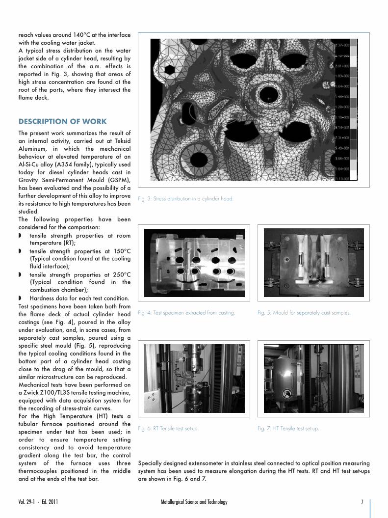
reach values around 140°C at the interfacewith the cooling water jacket.A typical stress distribution on the waterjacket side of a cylinder head, resulting bythe combination of the a.m. effects isreported in Fig. 3, showing that areas ofhigh stress concentration are found at theroot of the ports, where they intersect theflame deck.
DESCRIPTION OF WORKThe present work summarizes the result ofan internal activity, carried out at TeksidAluminum, in which the mechanicalbehaviour at elevated temperature of anAl-Si-Cu alloy (A354 family), typically usedtoday for diesel cylinder heads cast inGravity Semi-Permanent Mould (GSPM),has been evaluated and the possibility of afurther development of this alloy to improveits resistance to high temperatures has beenstudied.The following properties have beenconsidered for the comparison:w tensile strength properties at room
temperature (RT);w tensile strength properties at 150°C
(Typical condition found at the coolingfluid interface);
w tensile strength properties at 250°C(Typical condition found in thecombustion chamber);
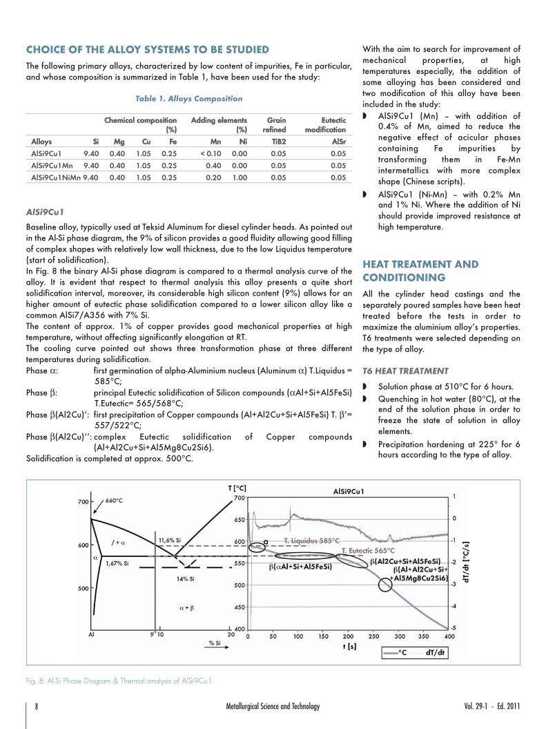
w Hardness data for each test condition.Test specimens have been taken both fromthe flame deck of actual cylinder headcastings (see Fig. 4), poured in the alloyunder evaluation, and, in some cases, fromseparately cast samples, poured using aspecific steel mould (Fig. 5), reproducingthe typical cooling conditions found in thebottom part of a cylinder head castingclose to the drag of the mould, so that asimilar microstructure can be reproduced.Mechanical tests have been performed ona Zwick Z100/TL3S tensile testing machine,equipped with data acquisition system forthe recording of stress-strain curves.For the High Temperature (HT) tests atubular furnace positioned around thespecimen under test has been used; inorder to ensure temperature settingconsistency and to avoid temperaturegradient along the test bar, the controlsystem of the furnace uses threethermocouples positioned in the middleand at the ends of the test bar.
Fig. 3: Stress distribution in a cylinder head.
Fig. 4: Test specimen extracted from casting. Fig. 5: Mould for separately cast samples.
Fig. 6: RT Tensile test set-up. Fig. 7: HT Tensile test set-up.
Specially designed extensometer in stainless steel connected to optical position measuringsystem has been used to measure elongation during the HT tests. RT and HT test set-upsare shown in Fig. 6 and 7.
8 Metallurgical Science and Technology Vol. 29-1 - Ed. 2011
CHOICE OF THE ALLOY SYSTEMS TO BE STUDIEDThe following primary alloys, characterized by low content of impurities, Fe in particular,and whose composition is summarized in Table 1, have been used for the study:
Baseline alloy, typically used at Teksid Aluminum for diesel cylinder heads. As pointed outin the Al-Si phase diagram, the 9% of silicon provides a good fluidity allowing good fillingof complex shapes with relatively low wall thickness, due to the low Liquidus temperature(start of solidification).In Fig. 8 the binary Al-Si phase diagram is compared to a thermal analysis curve of thealloy. It is evident that respect to thermal analysis this alloy presents a quite shortsolidification interval, moreover, its considerable high silicon content (9%) allows for anhigher amount of eutectic phase solidification compared to a lower silicon alloy like acommon AlSi7/A356 with 7% Si.The content of approx. 1% of copper provides good mechanical properties at hightemperature, without affecting significantly elongation at RT.The cooling curve pointed out shows three transformation phase at three differenttemperatures during solidification.Phase α: first germination of alpha-Aluminium nucleus (Aluminum α) T.Liquidus =
585°C;Phase β: principal Eutectic solidification of Silicon compounds (αAl+Si+Al5FeSi)
T.Eutectic= 565/568°C;Phase β(Al2Cu)’: first precipitation of Copper compounds (Al+Al2Cu+Si+Al5FeSi) T. β’=
557/522°C;Phase β(Al2Cu)’’: complex Eutectic solidification of Copper compounds
(Al+Al2Cu+Si+Al5Mg8Cu2Si6).Solidification is completed at approx. 500°C.
With the aim to search for improvement ofmechanical properties, at hightemperatures especially, the addition ofsome alloying has been considered andtwo modification of this alloy have beenincluded in the study:w AlSi9Cu1 (Mn) – with addition of
0.4% of Mn, aimed to reduce thenegative effect of acicular phasescontaining Fe impurities bytransforming them in Fe-Mnintermetallics with more complexshape (Chinese scripts).
w AlSi9Cu1 (Ni-Mn) – with 0.2% Mnand 1% Ni. Where the addition of Nishould provide improved resistance athigh temperature.
HEAT TREATMENT ANDCONDITIONINGAll the cylinder head castings and theseparately poured samples have been heattreated before the tests in order tomaximize the aluminium alloy’s properties.T6 treatments were selected depending onthe type of alloy.
T6 HEAT TREATMENT
w Solution phase at 510°C for 6 hours.w Quenching in hot water (80°C), at the
end of the solution phase in order tofreeze the state of solution in alloyelements.
w Precipitation hardening at 225° for 6hours according to the type of alloy.
Fig. 8: Al-Si Phase Diagram & Thermal analysis of AlSi9Cu1.
9Metallurgical Science and TechnologyVol. 29-1 - Ed. 2011
Before the tensile testing at HT (150 –250°C) all the test samples have been pre-conditioned at the test temperature for 500hours, in order to reproduce the “inservice” conditions of the over-agedmaterial and the microstructural“damages” caused by long exposure tohigh temperatures.
MECHANICAL TESTS RESULTSA summary of the test conditions analyzedfor the various alloys is reported in table 2,while the results obtained in the tensiletests, as well as on Brinell hardness, at
Tensile test (20°C)AlSi9Cu1 T6 500 h x 150°C Tensile test (150°C)
500 h x 250°C Tensile test (250°C)
Tensile test (20°C)AlSi9Cu1 Mn T6 500 h x 150°C Tensile test (150°C)
500 h x 250°C Tensile test (250°C)
Tensile test (20°C)AlSi9Cu1 NiMn T6 500 h x 250°C Tensile test (250°C)
Tensile test at room temperature
UTS (MPa) YTS (MPa) E% HB (Ø5 mm-250Kg)
AlSi9Cu1 270 235 1,0 94
AlSi9Cu1 + Mn 305 245 3,0 105
AlSi9Cu1 + Ni + Mn 310 270 1,3 106
room temperature and at 150 and 250°C are reported in the Figs. 9, 10 and 11.Figures reported in the tables and histograms are the average values measured for eachset of tested specimen, while the stress-strain curves show the results of a single specimenrepresentative of the typical behaviour of the alloy.
10 Metallurgical Science and Technology Vol. 29-1 - Ed. 2011
The following considerations can be drawn by the analysis of results obtained at RT (figure 9):w The behaviour of base alloy AlSi9Cu1 can be improved by the addition of Mn or Mn+Ni: in the first case UTS and elongation
increase significantly (reaching respectively 300 MPa and 3%), in the second both UTS (310 MPa) and YTS (270 MPa) grow, whileelongation remains stable.
w According to the increase of the strength, the hardness is also improved.
Fig. 10: Tensile test results at 150°C.
Tensile test at 150°C (conditioning)
UTS (MPa) YTS (MPa) E% HB (Ø5 mm-250Kg)
AlSi9Cu1 210 178 2,2 94
AlSi9Cu1 + Mn 233 211 4,8 100
At 150°C, Fig. 10, all the alloys show a reduction of tensile properties compared to RT conditions. UTS decreases approximately 20%in average, even if the AlSi9Cu1 (Ni-Mn) modified alloy has not been tested at this temperature, it is confirmed that AlSi9Cu1(Mn)maintains better elongation and UTS compared to the base alloy.At 250°C, Fig. 11, we can notice a further significant decrease of strength for all the alloys, with dramatic increase of elongation values.From the data in Fig. 11 it is evident that UTS of all the tested alloys drops well below 100 MPa, however the variant with Mn-Ni additionhas a slightly better behaviour than the others.
11Metallurgical Science and TechnologyVol. 29-1 - Ed. 2011
Fig. 11: Tensile test results at 250°C.
Tensile test at 250°C (conditioning)
UTS (MPa) YTS (MPa) E% HB (Ø5 mm-250Kg)
AlSi9Cu1 70 54 14,0 51
AlSi9Cu1 + Mn 75 58 21,0 53
AlSi9Cu1 + Ni + Mn 92 66 16,5 62
MICROSTRUCTURALEVALUATIONIn order to get a deeper understanding ofthe behaviour of the different alloys, amicrostructural evaluation was performedon the specimen after the tensile test and asuitable surface preparation of transversesection of samples.
AlSi9Cu1
This type of alloy is characterized by dendritestructure with a homogeneous distribution ofeutectic silicon shown in Fig. 12.
By the addition of appropriate elementssuch as strontium in the liquid metal, it ispossible to modify silicon morphologicalstructure from lamellar to globular duringthe solidification. This modificationtreatment improves the mechanicalproperties of the AlSi alloy by reducing thenotching effect of needle shaped naturaleutectic silicon (Fig. 13).Another important practice to improve themechanical properties and castingcharacteristics is to introduce inoculatingcompound like titanium and boron. Thistreatment of grain refinement allows to
have a fine distribution of first dendrite’sgermination, due to nucleation of Al3TiB2particles during the melt cooling.The strengthening effect of Cu in this alloyis linked to precipitation of secondaryeutectic phases of CuAl2 intermetallics,shown in Fig. 14. The heat treatment causesthe disappearance/solubilisation of CuAl2while the last solidified phaseAl5Mg8Cu2Si6 is partly solubilised.Silicon particles are rounded and moreagglomerated, whilst the iron compounddoesn’t show any shape modification.
12 Metallurgical Science and Technology Vol. 29-1 - Ed. 2011
Fig. 12: Typical dendrite structure of AlSi alloys. Fig. 13: AlSi9Cu1 – Globular distribution ofeutectic silicon.
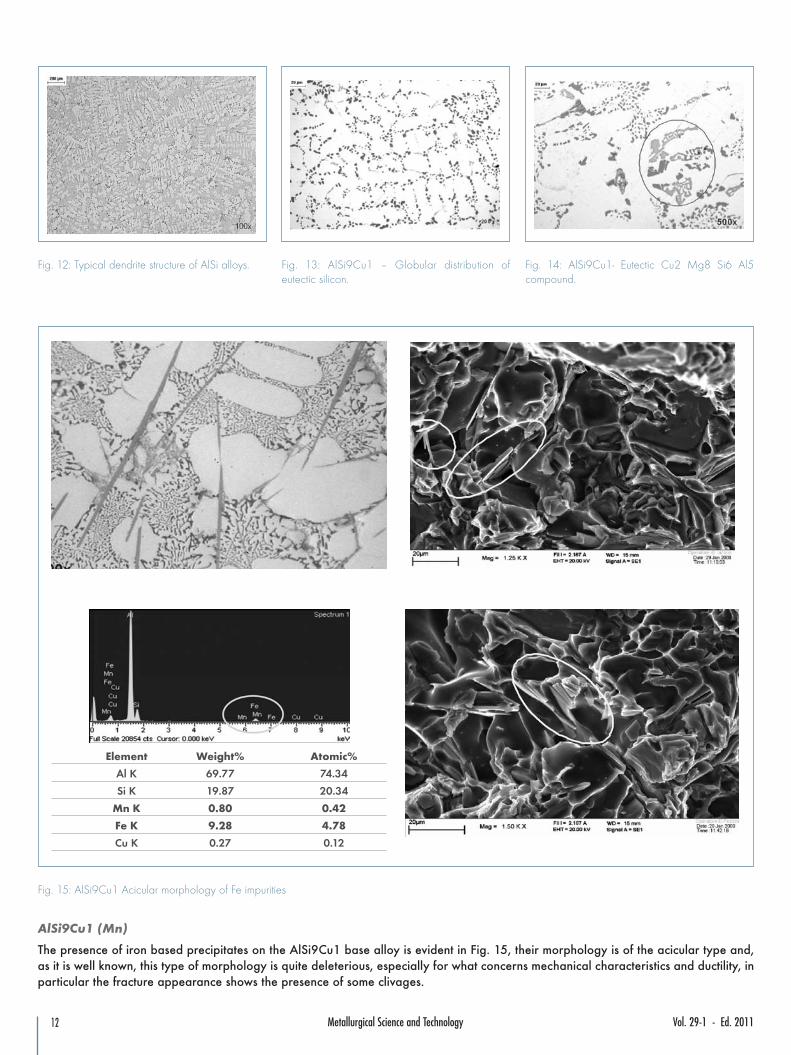
Fig. 15: AlSi9Cu1 Acicular morphology of Fe impurities
Element Weight% Atomic%
Al K 69.77 74.34
Si K 19.87 20.34
Mn K 0.80 0.42
Fe K 9.28 4.78
Cu K 0.27 0.12
AlSi9Cu1 (Mn)
The presence of iron based precipitates on the AlSi9Cu1 base alloy is evident in Fig. 15, their morphology is of the acicular type and,as it is well known, this type of morphology is quite deleterious, especially for what concerns mechanical characteristics and ductility, inparticular the fracture appearance shows the presence of some clivages.
13Metallurgical Science and TechnologyVol. 29-1 - Ed. 2011
With the addition of Mn the morphology of Fe compound changes from acicular type to complex shape, typical of Fe-Mn intermetallics(Chinese script, Fig. 16), improving the elongation properties of the alloy, due to the reduction of notching effect of Fe needles, thefracture surface now shows the consistent presence of dimples to state higher toughness properties. Because negative effects are notemphasized, it is possible to state that the modification of the base alloy with 0.5 % of manganese is beneficial.
Fig. 16: AlSi9Cu1 Mn - Morphology of Fe-Mn intermetallics
Element Weight% Atomic%
Al K 75.70 81.70
Si K 10.83 11.22
Mn K 9.50 5.03
Fe K 3.43 1.79
Cu K 0.55 0.25
Element Weight% Atomic%
CK 8.93 24.14
Al K 35.37 42.58
Si K 1.03 1.19
Mn K 38.73 22.90
Fe K 14.88 8.6
Cu K 1.06 0.54
14 Metallurgical Science and Technology Vol. 29-1 - Ed. 2011
AlSi9Cu1 (NiMn)
The second studied modification of the base alloy includes smaller Mn amount (0.2%), with the addition of 1% Ni. Also in this case, withrespect the basic alloy, the most relevant structure differences are always related to the modification of the morphology of the Fecontaining phases, that change from acicular ferrous compound type to complex shape, typical of Fe-Mn intermetallics and the acicularstructures are no longer observed. Moreover, the considerable percentage of nickel (1%), with reference to SEM analysis shown in Fig.17, contributes to the formation of solid solutions and mainly rounded eutectic components. In particular, it seems that nickel ties withcopper compound (CuAl2) improving the copper effect on resistance at high temperature.
Fig. 17: AlSi9Cu1 NiMn- Morphology of Fe-Mn intermetallics
Element Weight% Atomic%
Al K 82.89 84.03
Si K 12.77 15.35
Ni K 1.8 0.51
Cu K 2.25 0.41
Element Weight% Atomic%
Al K 92.61 96.62
Mn K 0.66 0.34
Ni K 1.53 0.73
Cu K 5.20 2.30
15Metallurgical Science and TechnologyVol. 29-1 - Ed. 2011
SUMMARY ANDCONCLUSIONSThe mechanical behaviour of Aluminumalloys, measured by means of tensile testand Brinell hardness, is strongly influencedby the test temperature and by theexposure time at high temperatures.The resistance of base Al-Si-Cu alloy isfairly good up to 150°C (temperature atwhich the material actually works in the
most stressed areas at the bottom of thewater jacket of a cylinder head), but dropsat 250°C.Some interesting improvements have beenachieved by modifying the composition ofthe base alloy with the addition of Mn andNi, resulting in an increase of strength andductility at both room and hightemperature.Based on the results achieved in the presentstudy it was decided to continue the
evaluation of the considered alloys also interms of High Cycle Fatigue and creepresistance at high temperature. This activityis at present on-going.Moreover the study will be continuedconsidering other binary alloys, mainlybased on Al-Mg and Al-Cu series, toevaluate their real potentiality towards thiskind of application. The obtained resultswill be presented and discussed in a secondpart of the paper
ACKNOWLEDGMENTSThe authors wish to thank the personnel at Teksid Aluminum R&D and testing Labs and Dario Pezzini of Materials Laboratory ofPolitecnico di Torino, Alessandria branch (Italy), for their precious contribution to the work.
Cylinder Heads Cast of Aluminum SAETechnical Paper Series SAE Technical PaperSeries 940153 (1994);
w L. Arnberg, G.Heiberg, K.Nogita,M.Raanes, A.L.Dons.: Effect of magnesium,iron and copper on eutectic solidification ofhypoeutectic aluminium-silicon alloys AFSAmerican Foundry Society Transactions 02-088 (2002);
w Blanda Lenczowsky, Hubert Koch, KlausEigenfelde, Burkhard Plege: New
developments of resistant alloys fromfoundry of aluminum to the hightemperatures Sonderdruck aus Gieberei 91(08/2004);
w J. Royset and N. Ryum: Scandium inaluminium alloys Published by Maney forthe institute And ASM (2005)
BIBLIOGRAPHY
w Pres. Kent R. Van Horn: AluminumProperties Physical Metallurgy and PhaseDiagrams, ASM American Society forMetals, (1967);
w Di Russo: Metallographic atlas of aluminumalloys from foundry, Brescia EditionEDIMET (1993);
w Paul H. Mikkola, John A.Redemske:Optimizing Proprerties of Automotive


![Documento di Consenso Internazionale sul Piede Diabetico 2005 [2].pdf · ancora una volta il Gruppo di Studio italiano sul piede diabetico è stato il primo gruppo nazionale a tradurlo](https://static.documents.pub/doc/80x56/5c6e661c09d3f2f3568b4b7d/documento-di-consenso-internazionale-sul-piede-diabetico-2005-2pdf-ancora.jpg)


