147
ALADDIN - User manual Rev. 23 of 08/07/2016 1 ALADDIN User manual 0123 Product cod. 1240211 ALADDIN HW2.0 Rev. 23 - 2016

ALADDIN - User manual Rev. 23 of 08/07/2016
1
ALADDIN
User manual
0123
Product cod. 1240211 ALADDIN HW2.0 Rev. 23 - 2016

ALADDIN - User manual Rev. 23 of 08/07/2016
2
Caution: Federal law restricts this device to sale by or on the order of an optometrist, optician, or an
ophthalmologist.
Thank you for choosing this product.
Please read the information in this manual carefully. You must be familiar with its contents in order to work
with the device.
The manufacturer has a policy of continuous improvement of its products, so it is possible that some
instructions, specifications and pictures in this manual may differ slightly from the product you purchased.
The manufacturer also reserves the right to make any changes to this manual without notice.
The original text of this manual is in English.
SW v.: 1.5.x
Manufacturer VISIA imaging S.r.l. Via Martiri della Libertà 95/e 52027 San Giovanni Valdarno (AR) Italy
Distributor Topcon Europe Medical B.V. Essebaan 11 2908 LJ Capelle a/d IJssel The Netherlands www.topcon.eu [email protected]

ALADDIN - User manual Rev. 23 of 08/07/2016
3
Contents 1 Intended Use ............................................................................................................................................. 7
1.1 Description of functionalities ............................................................................................................ 7
1.2 Users .................................................................................................................................................. 9
1.3 Positioning the patient .................................................................................................................... 10
1.4 Places of use .................................................................................................................................... 10
1.5 Contraindications ............................................................................................................................ 10
2 Accessibility and scope of the manual .................................................................................................... 11
3 Introduction ............................................................................................................................................ 12
3.1 Main characteristics ........................................................................................................................ 12
4 Precautions ............................................................................................................................................. 13
4.1 EMC table ........................................................................................................................................ 14
5 Symbols ................................................................................................................................................... 16
5.1 Labeling on the device ..................................................................................................................... 17
6 Safety instructions .................................................................................................................................. 18
6.1 General ............................................................................................................................................ 18
6.2 Electrical safety ................................................................................................................................ 19
6.3 LED emission safety ......................................................................................................................... 19
6.4 Installation with external devices or IT Network............................................................................. 19
6.5 Transport and packaging ................................................................................................................. 20
6.6 Cleaning ........................................................................................................................................... 20
6.7 Package contents ............................................................................................................................. 20
6.8 Checking the measurements ........................................................................................................... 20
6.9 Cybersecurity ................................................................................................................................... 21
7 Product warranty and reliability ............................................................................................................. 22
8 Legal provisions ...................................................................................................................................... 22
9 Components ............................................................................................................................................ 23
9.1 Main Body ........................................................................................................................................ 23
9.2 Other components .......................................................................................................................... 24
10 Installation /uninstallation of the system ............................................................................................... 25
10.1 Installing the system ........................................................................................................................ 25
10.2 Uninstalling the system ................................................................................................................... 28
11 ALADDIN accessories and equipment ..................................................................................................... 31
11.1 Standard equipment ........................................................................................................................ 31
ALADDIN - User manual Rev. 23 of 08/07/2016
4
12 Setting up the instrument ....................................................................................................................... 32
12.1 Connection modes ........................................................................................................................... 32
13 OPERATING INSTRUCTIONS .................................................................................................................... 33
13.1 General description of functionalities ............................................................................................. 33
13.1.1 General instructions ................................................................................................................ 34
13.2 Checking the calibration .................................................................................................................. 34
13.3 Patient entry/selection .................................................................................................................... 38
13.3.1 Creating a new patient ............................................................................................................ 39
Entering special characters ................................................................................................................ 39
Selecting crystalline and vitreous body type ...................................................................................... 39
13.3.2 Selecting or modifying a patient .............................................................................................. 43
Open an examination or acquire data for the selected patient ......................................................... 43
Delete or edit the selected patient .................................................................................................... 43
Insert the Post-Op (after surgery) refraction data ............................................................................. 44
13.3.3 Selecting a patient from Server ............................................................................................... 45
Start an exam from the Waiting Room .............................................................................................. 47
13.4 Acquisition environment: general instructions ............................................................................... 48
13.4.1 Description of the Acquisition screen...................................................................................... 50
Description of results ......................................................................................................................... 50
Errors in Measurements ..................................................................................................................... 51
Biometry ............................................................................................................................................. 52
Pupillometry ....................................................................................................................................... 53
13.5 Full biometry acquisition (K-AL-ACD) .............................................................................................. 53
13.5.1 Acquisition procedure ............................................................................................................. 54
13.5.2 Further adjustments for the anterior chamber depth ............................................................ 56
13.6 Acquisition of axial length measurements (AL) ............................................................................... 56
13.7 Acquisition of the anterior chamber measurement (ACD) ............................................................. 57
13.8 Keratometry acquisition (KER) ......................................................................................................... 59
13.9 Acquisition of the dynamic, photopic, mesopic pupillometry........................................................ 61
13.10 Report printing ............................................................................................................................ 63
13.10.1 Available Printers ................................................................................................................. 64
13.10.2 Custom Reports ................................................................................................................... 65
13.11 Data Exportation .......................................................................................................................... 66
13.12 IOL CALCULATION ........................................................................................................................ 68
13.12.1 Data ..................................................................................................................................... 69
13.12.2 Spherical IOL calculation ...................................................................................................... 71

ALADDIN - User manual Rev. 23 of 08/07/2016
5
13.12.3 Toric IOL calculation ............................................................................................................ 73
13.12.4 Post Refractive IOL calculation ............................................................................................ 76
13.13 MEASUREMENTS ......................................................................................................................... 79
13.13.1 TOPOGRAPHIC MAP (KER) ................................................................................................... 79
Topographic map indices ............................................................................................................... 80
Keratometry ................................................................................................................................... 80
Keratorefractive indices ................................................................................................................. 80
Keratoconus ................................................................................................................................... 81
Pupil ............................................................................................................................................... 82
Profile ............................................................................................................................................. 84
13.13.2 Zernike ................................................................................................................................. 85
13.13.3 AXIAL LENGTH (AL) .............................................................................................................. 88
13.13.4 ANTERIOR CHAMBER DEPTH (ACD) ..................................................................................... 89
13.13.5 PUPILLOMETRY (PUP) .......................................................................................................... 89
Display............................................................................................................................................ 90
Sequences ...................................................................................................................................... 90
Dynamic ......................................................................................................................................... 90
Photopic, Mesopic ......................................................................................................................... 91
Functions........................................................................................................................................ 91
Graphs ............................................................................................................................................ 91
13.13.6 WHITE TO WHITE ................................................................................................................. 94
13.14 EXAMINATION DATA SAVING ...................................................................................................... 97
13.15 SETTINGS...................................................................................................................................... 98
13.15.1 General ................................................................................................................................ 99
13.15.2 Measurements ..................................................................................................................... 99
Scales ............................................................................................................................................. 99
Topography Map Color scale ....................................................................................................... 102
Map Option .................................................................................................................................. 103
Pupillometry ................................................................................................................................ 103
13.15.3 Surgeons ............................................................................................................................ 104
13.15.4 IOL ...................................................................................................................................... 105
General ........................................................................................................................................ 105
Preset ........................................................................................................................................... 106
IOL list .......................................................................................................................................... 108
13.15.5 Connectivity ....................................................................................................................... 115
Network folder configuration ...................................................................................................... 115
XML Export ................................................................................................................................... 116
IMAGEnet i-base software ........................................................................................................... 116
ALADDIN - User manual Rev. 23 of 08/07/2016
6
IMAGEnet 6 Server software ....................................................................................................... 117
Export to External Software settings ........................................................................................... 117
DICOM .......................................................................................................................................... 119
13.15.6 Admin ................................................................................................................................ 121
Report .......................................................................................................................................... 121
Remote Assistance ....................................................................................................................... 122
Updating the integrated software ............................................................................................... 123
Backup & Restore ........................................................................................................................ 128
Closing the software .................................................................................................................... 132
14 Operating voltage and fuse change ...................................................................................................... 133
14.1 Changing the operating voltage .................................................................................................... 133
14.2 Changing the fuse .......................................................................................................................... 134
15 Technical specifications ........................................................................................................................ 135
15.1 General .......................................................................................................................................... 135
15.2 Electrical data ................................................................................................................................ 135
15.3 Optical radiation ............................................................................................................................ 136
15.4 Performance Testing ..................................................................................................................... 137
15.5 Information on measurements ..................................................................................................... 139
15.6 Environmental conditions ............................................................................................................. 139
15.7 Mechanical Specifications ............................................................................................................. 140
15.8 Other Specifications: Onboard PC component specifications ....................................................... 140
16 Declaration of conformity ..................................................................................................................... 141
17 Appendix: Installing an external printer .............................................................................................. 142
17.1 Getting drivers and transferring them to ALADDIN ...................................................................... 142
17.2 Disabling the Write Filter ............................................................................................................... 142
17.3 Installing a local printer (USB) ....................................................................................................... 143
17.4 Installing a network printer (LAN) ................................................................................................. 146
17.5 Re-Enabling the Write Filter .......................................................................................................... 147

ALADDIN - User manual Rev. 23 of 08/07/2016
7
1 Intended Use
ALADDIN is intended for biometric determination of the following ocular measurements: axial length, corneal radius, corneal cylinder axis, anterior chamber depth, white-to-white (WTW) and pupil diameter of the human eye. ALADDIN also measures corneal topography.
For patients who are candidates for intraocular lens (IOL) implantation, ALADDIN also aids in the calculation of the appropriate IOL power and type to be implanted.
ALADDIN is intended for use by physicians and eye-care professionals and may only be used under the supervision of a physician.
1.1 Description of functionalities
Aladdin is a combined device for the measurement of various parameters used in the application of intraocular lenses.
The instrument can work in two different modes:
1. Consecutive acquisition of all the measurements available on the eye 2. Individual acquisitions for each type of measurement
Aladdin includes six types of measurement in a single instrument.
Axial length(AL)
Corneal topography
Keratometry(KER)
Corneal diameter (white-to-white)
Pupillometry
Anterior chamber depth (ACD)
Axial length is the distance between the cornea and the inner limiting membrane. It is measured with a low-coherence interferometry system with a super luminescent diode. The measuring range goes from 15 mm to 38 mm Keratometry is used to measure the corneal curvature. It is based on the reflection of the Placido disk on the eye at a controlled working distance for high measuring precision. Aladdin allows the user to acquire the corneal topography of the eye. The “Corneal Map” is obtained from the reflection of 24 rings of the Placido disk at a distance of 80 millimetres from the patient's eye. The position of the device in relation to the patient’s eye serves as the starting point to make adjustments in the respective measurement modes. With the acquisition of the corneal topography, the Corneal Diameter can be determined. The Corneal Diameter is also known as "white- to- white" distance.
The pupillometry is performed with LEDs of different wavelengths. In particular, the instrument uses infrared LEDs to dilate the pupil and white LEDs to reproduce photopic light conditions and to contract the pupil (dynamic pupillometry).
ACD (anterior chamber depth) is the distance between the anterior surface of the crystalline (anterior capsule) and the outermost stratum of the cornea (epithelium), measured along the optical axis where the latter is biggest. This measurement is performed using the reflection principle of a slit light projected onto the anterior surfaces of the eye.

ALADDIN - User manual Rev. 23 of 08/07/2016
8
Caution should be practised when using the device’s ACD measurement for any given intraocular lens
calculation because of the high variability of this measurement.
The ACD measurement is the distance between corneal epithelium and the crystalline lens surface.
Aladdin has an onboard PC with the dedicated software that provides all the functionalities described. The information obtained from the measurements can be used for various applications, for example: Cataract operations, IOL calculation, IOL toric calculation and post lasik calculation. The intraocular lens power suggestion is made using scientifically recognised formulae: Holladay 1, Haigis, Hoffer Q, SRK / T, SRK II, Camellin-Calossi, Shammas No history.
The Haigis, HofferQ, Holladay, SRK® II and SRK®/T formulae are implemented in the software.
Please refer to the following literature references on the formulae (in case of specific questions please
contact Visia Imaging):
• Haigis: http://www.augenklinik.uni-wuerzburg.de/uslab/ioltxt/haid.htm
• HofferQ: HOFFER KJ: The Hoffer Q formula: A comparison of theoretic and regression formulas.
J Cataract Refract Surg, 19:700-712, 1993; ERRATA 20:677, 1994
• Reply: Errata in printed Hoffer Q formula. Journal of Cataract & Refractive Surgery, Volume 33,
Issue 1, Pages 2-3, January 2007, Authors:Kenneth J. Hoffer, MD
• Holladay: HOLLADAY JT, PRAGER TC, CHANDLER TY, MUSGROVE KH, LEWIS JW, RUIZ RS: A three-
part system for refining intraocular lens power calculations. J Cataract Refract Surg, 14:17-24,
1988
• SRKII: RETZLAFF J: A new intraocular lens calculation formula, Am Intra-Ocular Implant Soc J
6:148-152, 1980
• SRK/T: RETZLAFF J, SANDERS DR, KRAFF MC: Development of the SRK/T intraocular lens implant
power calculation formula. J Cataract Refract Surg 16 (3):333-340, 1990
Correction of corneal radii/corneal refraction after corneal refractive surgery:
• HOLLADAY JT: IOL calculations following RK. Refract Corneal Surg 5(3):203, 1989
• HOFFER KJ: Intraocular lens power calculation for eyes after refractive keratotomy. J Refract Surg
11:490:493, 1995
Calculation of phakic implants:
• vd HEIJDE GL, FECHNER PU, WORST JGF: Optische Konsequenzen der Implantation einer
negativen Intraokularlinse bei myopen Patienten. Klin MB1 Augenheilk 192:99-102, 1988
• HOLLADAY JT: Refractive power calculations for intraocular lenses in the phakic eye. Am J
Ophthalmol 116:63-66, 1993
• HAIGIS W: Biometry in complicated situations, 9th Conv. of DGII 1995, Rochels et al (Hrsg.),
Springer, 17-26, 1996
Relations between ultrasound and optical biometer calculation constants:
• RETZLAFF J, SANDERS DR, KRAFF MC (1990): Lens Implant Power Calculation - A manual for
ophthalmologists & biometrists, 3rd edition, Slack Inc, Thorofare NJ, USA
• HAIGIS W, LEGE B, MILLER N, SCHNEIDER B: Comparison of immersion ultrasound biometry and
partial coherence interferometry for IOL calculation according to Haigis, Graefes Arch Clin Exp
Ophthalmology (2000) 238:765-773

ALADDIN - User manual Rev. 23 of 08/07/2016
9
• HOLLADAY, JT: International intraocular lens implant registry 2003. J Cataract Refract Surg (2003)
29:176-197
• HAIGIS W: Relations between optimized IOL constants. Symposium on Cataract, IOL and
Refractive Surgery of the American Society of Cataract and Refractive Surgery (ASCRS),
Philadelphia, PA, USA, June 1-5, 2002, Abstracts, p.112, 2002
Intraocular lens power calculation AFTER corneal refractive surgery:
• Camellin-Calossi: M. Camellin, MD; A. Calossi, Optom “A new formula for intraocular lens power
calculation after refractive Corneal Surgery”, Journal of Refractive Surgery, vol. 22 Feb. 2006.
This formula is for use in patients who have had prior refractive surgery. Each such patient is
unique and results may vary widely. You should interpret all IOL power recommendations with
caution.
• Shammas No-history: SHAMMAS H.J., SHAMMAS M.C: “No-history method of intraocular lens power calculation for cataract surgery after myopic laser in situ keratomileusis”, J Cataract Refract Surg 2007; 33:31–36 Q 2007 ASCRS and ESCRS.
• Shammas No-history: SHAMMAS H.J., SHAMMAS M.C., GARABET A., KIM J.H., SHAMMAS A. ,
LABREE L.: Correcting the Corneal Power Measurements for Intraocular Lens Power Calculations
After Myopic Laser In Situ Keratomileusis” - American Journal of Ophthalmology (Impact Factor:
4.02). 10/2003; 136(3):426-32.
• Shammas No-history: SHAMMAS H.J., SHAMMAS M.C., HILL W.E.: Intraocular lens power
calculation in eyes with previous hyperopic laser in situ keratomileusis” - J Cataract Refract Surg
2013; 39:739–744 Q 2013 ASCRS and ESCRS.
Toric IOL calculation:
HB Fam, KL Lim: Meridional analysis for calculating the expected spherocylindrical refraction in
eyes with toric intraocular lenses. Journal of Cataract & Refractive Surgery, 2007 - Elsevier
N Alpins: Astigmatism analysis by the Alpins method. Journal of Cataract & Refractive Surgery,
2001 - Elsevier
G Savini, KJ Hoffer, M Carbonelli, P Ducoli: Influence of axial length and corneal power on
the astigmatic power of toric intraocular lenses - Journal of Cataract & …, 2013 - Elsevier
JT Holladay, TV Cravy, DD Koch: Calculating the surgically induced refractive change following
ocular surgery. - Journal of Cataract & Refractive Surgery, 1992 – Elsevier
Abulafia A, Koch DD, Wang L, Hill WE, Assia EI, Franchina M, Barrett GD: New regression formula
for toric intraocular lens calculation. – Journal of Cataract & Refractive Surgery, 2016 - Elsevier
1.2 Users
Users: medical staff, opticians, ophthalmologists.
For surgery and intraocular lens implantation, the device can only be used under medical supervision. For
the other applications, the device must be used by qualified personnel.

ALADDIN - User manual Rev. 23 of 08/07/2016
10
1.3 Positioning the patient
The patient must be positioned in such a way that the distance from the device to the eye is 80 mm.
A steady head position and the correct device-to -patient distance is promoted by resting the patient’s head
well against the chin rest and forehead band.
A correct alignment with the patient’s pupils can be visually checked by the operator referring to the two
lines on the forehead supports.
Figure 1
It is necessary to tell the patient to look steadily at the fixation point in the center of the Placido disk.
The position of the device in relation to the patient’s eye thus found is a starting point for fine measurement
adjustments.
The patient does not use the controls.
The patient may be an elderly person, an invalid, or a child. In any case the device is to be controlled by the
aforementioned specialized personnel.
1.4 Places of use
The intended places of use are: health care centers, doctors' surgeries, operating theatres.
1.5 Contraindications
Patient could have a dazzle effect, after the exam, dues to the device lights, but it disappears in few minutes.

ALADDIN - User manual Rev. 23 of 08/07/2016
11
2 Accessibility and scope of the manual Keep these instructions in a safe place close to the device. The manual must be at hand at all times. For best
use of the instrument, read the instructions carefully.
The purpose of this manual is to inform the user as to all the device's functions, settings, safety, installation,
maintenance, cleaning and storage instructions.

ALADDIN - User manual Rev. 23 of 08/07/2016
12
3 Introduction
3.1 Main characteristics
ALADDIN is a multifunction medical device used for the detection of various biometric parameters,
particularly useful for the calculation of spherical, toric or personalized intraocular lenses. It records a wide
range of parameters, which are acquired by using different techniques.
Optical Biometry: by means of the low-coherence optical interferometry method, ALADDIN executes axial
length measurements (between 15 and 38mm).
Anterior chamber depth: slit light projection - by projecting a slit of certain characteristics onto the eye, you
can determine the length of the optical axis of the anterior chamber, a very important measurement for the
calculation of IOL.
Topography: the device acquires a topographic map of the patient of approximately 6,200 points using a 24-
ring Placido disk to show the description of the corneal surface. This measurement also provides a
Keratometry at 3mm, 5mm and 7mm 7mm (or at 2,4,6 mm depending on the settings) with the respective
corneal astigmatism.
Pupillometry: for an accurate calculation of intraocular lenses, the instrument has a set of LEDs onboard
that allows a measurement of Photopic, Mesopic and Dynamic pupillometry.
White-to-White: as a result of the corneal topography and by means of an internal software algorithm, a
white-to-white value can be obtained, i.e. the corneal diameter recorded at the limbus.
The software can give suggestions for the choice of intraocular lens based on several different formulae.
Similarly, a database of intraocular lenses is also implemented. Before the calculation is made, the data for
the desired lens must be entered.
ALADDIN also covers all the basic functions of corneal topography for recording some keratorefractive
parameters.

ALADDIN - User manual Rev. 23 of 08/07/2016
13
4 Precautions
This electronic instrument is a precision tool. Make sure to use it and keep it in a suitable place, at a normal
temperature, humidity and atmospheric pressure out of direct sunlight.
To ensure proper functioning, install the instrument in a vibration-free location.
Connect all cables correctly before use.
Use the recommended network voltage.
When the instrument is not in use, turn off the power supply and protect it from the sun and from
dust.
To obtain accurate and reliable measurements, keep the measuring cone clean and free of dust.
This product conforms to the EMC standard (IEC 60601-1-2 3rd Edition).
- ELECTRICAL MEDICAL DEVICES require special EMC precautions and must be installed and activated in accordance with the EMC instructions provided in the accompanying documentation.
- Portable RF communication instruments may interfere with medical devices. - Use of accessories and cables other than those supplied with the instrument, except cables sold by
the equipment manufacturer as spare parts, may lead to an increase in emissions and reduce the device's or system's immunity.
- The eventual cables connected to USB and LAN ports must be less than 3 meters length. - The device must not be used in contact with other devices.
If use of the device in contact with other instruments is unavoidable, check that the device works properly in the required configuration.
Caution should be practised when using the device’s ACD measurement for any given intraocular lens
calculation because of the high variability of this measurement.
The ACD measurement is the distance between corneal epithelium and the crystalline lens surface.
The FDA labelling for some IOLs contain sizing based upon white-to-white measurements derived from studies in which this measurement is done with callipers. It is unknown whether the white-to-white measurement from this device yields results systematically biased compared to those from calliper measurements. Thus, sizing based upon white-to-white measurements from this device may not be consistent with those based upon measurements with callipers.
ALADDIN - User manual Rev. 23 of 08/07/2016
14
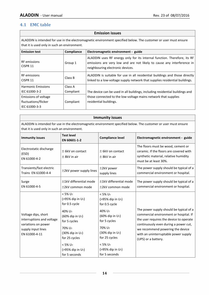
4.1 EMC table
Emission issues
ALADDIN is intended for use in the electromagnetic environment specified below. The customer or user must ensure
that it is used only in such an environment.
Emission test Compliance Electromagnetic environment - guide
RF emissions CISPR 11
Group 1
ALADDIN uses RF energy only for its internal function. Therefore, its RF
emissions are very low and are not likely to cause any interference in
neighbouring electronic devices.
RF emissions
CISPR 11 Class B
ALADDIN is suitable for use in all residential buildings and those directly
linked to a low-voltage supply network that supplies residential buildings.
Harmonic Emissions
IEC 61000-3-2
Class A
Compliant The device can be used in all buildings, including residential buildings and
those connected to the low-voltage mains network that supplies
residential buildings.
Emissions of voltage
fluctuations/flicker
IEC 61000-3-3
Compliant
Immunity issues
ALADDIN is intended for use in the electromagnetic environment specified below. The customer or user must ensure
that it is used only in such an environment.
Immunity issues Test level
EN 60601-1-2 Compliance level Electromagnetic environment - guide
Electrostatic discharge
(ESD)
EN 61000-4-2
6kV on contact
8kV in air
6kV on contact
8kV in air
The floors must be wood, cement or
ceramic. If the floors are covered with
synthetic material, relative humidity
must be at least 30%.
Transients/fast electric
Trains EN 61000-4-4 2kV power supply lines
2kV power
supply lines
The power supply should be typical of a
commercial environment or hospital.
Surge
EN 61000-4-5
1kV differential mode
2kV common mode
1kV differential mode
2kV common mode
The power supply should be typical of a
commercial environment or hospital.
Voltage dips, short
interruptions and voltage
variations on power
supply input lines
EN 61000-4-11
< 5% UT
(>95% dip in UT)
for 0.5 cycle
40% UT
(60% dip in UT)
for 5 cycles
70% UT
(30% dip in UT)
for 25 cycles
< 5% UT
(>95% dip in UT)
for 5 seconds
< 5% UT
(>95% dip in UT)
for 0.5 cycle
40% UT
(60% dip in UT)
for 5 cycles
70% UT
(30% dip in UT)
for 25 cycles
< 5% UT
(>95% dip in UT)
for 5 seconds
The power supply should be typical of a
commercial environment or hospital. If
the user requires the device to operate
continuously even during a power cut,
we recommend powering the device
with an uninterruptable power supply
(UPS) or a battery.

ALADDIN - User manual Rev. 23 of 08/07/2016
15
Immunity aspects at RF
The device is intended for use in the electromagnetic environment specified below. The customer or the user of the device
must ensure that it is used only in such an environment.
Portable and mobile RF communication devices must be used no closer to any part of the device, including the cables, than the
recommended separation distance, calculated from the equation applicable to the frequency of the transmitter.
Immunity test Test level
EN 60601-1-2
Compliance
level
Electromagnetic environment – guide
Recommended separation distance (where P is the maximum output power
rating of the transmitter in Watts (W) according to the transmitter
manufacturer and d is the recommended separation distance in meters (m)).
Conducted RF
EN 61000-4-6
3 Vrms
from 150kHz to
80MHz
3 Vrms
from 150kHz to
80MHz
d = 1.2 P from 150kHz to 80MHz
Radiated RF
EN 61000-4-3
3 V/m
from 80MHz to
2.5GHz
3 V/m
from 80MHz to
2.5GHz
d = 1.2 P from 80 MHz to 800 MHz
d = 2.3 P from 800 MHz to 2.5 GHz
Field strengths from fixed RF transmitters, as determined in an electromagnetic site survey, should be less than the
compliance level in each frequency range. Interference may occur in the vicinity of equipment marked with the following
symbol:
Recommended separation distance between portable and mobile radio communication devices and
the ALADDIN device
ALADDIN is intended for use in an electromagnetic environment in which radiated RF disturbances are under control. The customer or
the user of the device can help prevent electromagnetic interference by maintaining a minimum distance between mobile and
portable RF communication devices (transmitters) and the ALADDIN device as recommended below, according to the maximum
output power of the radio communication devices.
Maximum nominal
output power of the
transmitter (W)
Separation distance according to the frequency of the transmitter (m)
150kHz to 80MHz
d = 1.2 P
80MHz to 800MHz
d = 1.2 P
800MHz to 2GHz
d = 2.3 P
0.01 0.12 0.12 0.23
0.1 0.38 0.38 0.73
1 1.2 1.2 2.3
10 3.8 3.8 7.3
100 12 12 23
For transmitters with maximum output powers not listed above, the recommended separation distance d in meters (m) can be calculated
using the equation applicable to the frequency of the transmitter, where P is the nominal maximum output power of the transmitter in
Watts (W) according to the transmitter manufacturer.
Note:
(1) At 80 MHz and 800 MHz the separation distance of the higher frequency range applies.
(2) These guidelines may not be applicable in all situations. Electromagnetic propagation is affected by absorption and reflection from
structures, objects and people.
Power frequency
magnetic field
EN 61000-4-8
3 A/m 3 A/m
Power frequency magnetic fields must
have levels characteristic of a typical
commercial or hospital environment.

ALADDIN - User manual Rev. 23 of 08/07/2016
16
5 Symbols
Symbols IEC
publications Description
IEC 60417-
5840
CLASS I DEVICE ACCORDING TO EN 60601-1
APPLIED PART TYPE B
PRODUCT COMPLIANT WITH DIRECTIVE 93/42/EC
Type A EN ISO
19980 CORNEAL TOPOGRAPHY ACCORDING TO ISO 19980:2005
IEC 60417-
5032 ALTERNATING CURRENT
ISO 7010-
W001 GENERAL WARNING
EN ISO
15223-1 REFERENCE OR MODEL NUMBER
ISO 7010-
M002 FOLLOW THE INSTRUCTIONS FOR USE
EN ISO
15223-1 MANUFACTURER
Group 1 EN ISO
15004-2
PRODUCT CLASSIFIABLE AS GROUP 1 IN ACCORDANCE WITH
EN ISO 15004-2
EN 62471 PRODUCT CLASSIFIABLE AS EXEMPT GROUP IN ACCORDANCE
WITH EN 62471
EN ISO
15223-1
TEMPERATURE LIMITATION
Indicate the temperature limits to which the medical device can
be safely exposed.
EN ISO
15223-1
HUMIDITY LIMITATION
Indicate the range of humidity to which the medical device can
be safely exposed.
EN ISO
15223-1
ATHMOSPHERIC PRESSURE LIMITATION
Indicate the range of atmospheric pressure to which the
medical device can be safely exposed.
EXEMPT GROUP
EN62471
ALADDIN - User manual Rev. 23 of 08/07/2016
17
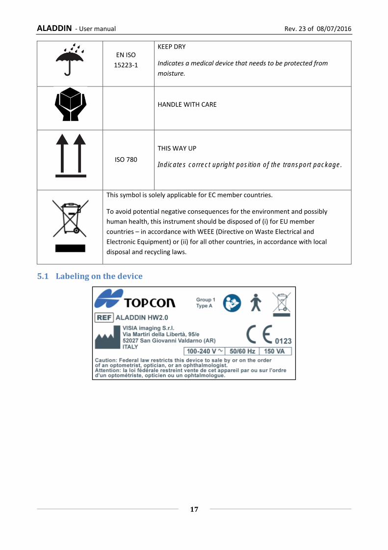
EN ISO
15223-1
KEEP DRY
Indicates a medical device that needs to be protected from
moisture.
HANDLE WITH CARE
ISO 780
THIS WAY UP
Indicates correct upright position of the transport package.
This symbol is solely applicable for EC member countries.
To avoid potential negative consequences for the environment and possibly
human health, this instrument should be disposed of (i) for EU member
countries – in accordance with WEEE (Directive on Waste Electrical and
Electronic Equipment) or (ii) for all other countries, in accordance with local
disposal and recycling laws.
5.1 Labeling on the device

ALADDIN - User manual Rev. 23 of 08/07/2016
18
6 Safety instructions
6.1 General
ALADDIN should be used only for its intended purposes as detailed in this manual.
It must be installed by qualified personnel.
The device must be used in the environmental conditions as specified in this document.
The least favorable environment is defined as the maximum values of temperature for the unit to be
operating in, while the unit is consuming the maximum current. The environmental value is stated as
+40°C. The maximum current absorption occurs during full biometry acquisition.
The maximum temperature of applied parts (chinrest and headrest) can exceed 41°C when the device is
used at environmental temperature close to 40°C. The device temperature doesn’t exceed 48°C anyway.
Considering the examination duration, the patient condition and the parts that are in contact with the
patient, there aren’t any known contraindications about to the contact with the device.
If the device has just been delivered or has been subjected to thermal shock, wait at least one
hour before making measurements on patients.
Keep this manual at hand close to the device at all times.
The physician or device user must inform the patient of the pertinent safety instructions and
ensure that they are adhered to.
Connect the device to the supply mains using one of the cables supplied with the device
Position the unit so that it is not difficult to disconnect the plug for connection to the supply main.
Perform all the control functions (detailed in the relative section in this document) before carrying
out measurements on patients. In addition, if software interface shows an “Initializing error” warning,
don’t go on with measurements. Also “Low repeatability of measure” warning originates a wrong IOL
calculation.
Only personnel with the appropriate training and experience may use the device and interpret the
results.
Turn off the device if it is not going to be used for a long period of time.
If external forces act on the device (e.g. if it is knocked or dropped), it must be thoroughly checked
before proceeding to examine patients. To do this, refer to the relative section in this manual. If
necessary, send the device in for repair.
Use only original ALADDIN accessories and spare parts specific for this device.
Remove all the covering (dust sheet) from the device before turning it on.
Do not use the device close to highly inflammable materials or in areas with an explosion hazard.
Unauthorized installation of software in the device is forbidden.
After the examination, the patient may be slightly dazed. It is recommended to advise the patient
to wait a few minutes before driving or performing actions that require perfect vision.
When operating the chinrest up/down switch, be careful not to pinch the patient’s hand. The
patient may be injured.
ALADDIN - User manual Rev. 23 of 08/07/2016
19
6.2 Electrical safety
To avoid risk of electric shock, this device must be connected to supply mains with protective
earth.
ALADDIN has an on-board power supply unit installed. For connection to the mains, use only the
manufacturer-approved cables provided with the device.
Before performing maintenance on the device, turn it off and disconnect the power cable.
Do not touch the LAB/USB ports contacts and the patient at the same time.
6.3 LED emission safety
The light emitted from this instrument is not potentially hazardous.
ALADDIN has a series of LEDs of various types and powers installed. All the characteristics are detailed in the
Technical Specifications section in this manual.
The LED groups comply with the emission limits for the Group 1 instruments of the standard UNI EN ISO
15004-2.
All sources are classifiable as EXEMPT GROUP according to EN 62471.
6.4 Installation with external devices or IT Network
ALADDIN complies with the CE marking requirements.
Before connecting an external device, such as a computer, printer, monitor, keyboard, mouse or
other devices, make sure that they comply with the EN 60950-1 standard and have the CE marking.
When ALADDIN is installed in rooms for medical use, the PC and the connected printer must be powered
by means of an IEC 60601-1 compliant insulating transformer.
If ALADDIN is installed in rooms for medical use without a computer, it is not necessary to use an
insulating transformer.
Do not use mobile phones or other devices not compliant with the requirements of class B EMC close to
ALADDIN.
Every external device that has to be connected to ALADDIN must have a connection cable (USB or
LAN) with a maximum length of 3 m.
The purpose of ALADDIN connection to an IT network is report printing and remote technical assistance.
The ALADDIN USB port must be connected to printer with USB or LAN interface. Ask Topcon technical
assistance for printer driver installation.
The ALADDIN can be connected to a Local Area Network (LAN) through the LAN connector. The network
must have Ethernet protocol (IEEE 802.3). Ask Topcon technical assistance and the system administrator
for ALADDIN and network settings.
The purpose of ALADDIN connection is saving PDF report on an external network folder or technical
service intervention on the machine.
Connection of ALADDIN to a computer network that includes other equipment could result in previously
unidentified RISKS; identify, analyze, and control such RISKS (refer to IEC 60601-1:2005).
Subsequent changes to a computer network could introduce new RISKS and require new analysis.
ALADDIN - User manual Rev. 23 of 08/07/2016
20
Changes to the computer network include:
Changes in computer or data network configuration
Connection of additional items to computer network
Disconnecting items from computer network
Update of equipment connected to computer network
Upgrade of equipment connected to computer network
The term computer network used here corresponds to the term network/data coupling in IEC 60601-
1:2005.
6.5 Transport and packaging
The device must be transported and stored in its original packaging.
For the storage and transport conditions, refer to the relative section in this document.
Carefully keep the original packaging in order to use it if you need to transport the device.
To move the device for short distances (without packaging) and to insert it in and remove it from the
original packaging, grip the device with both hands, one on the front headrest arch and the other in the
recess on the rear of the device (where the locking system is).
Completely unscrew the two transportation locks and the semi-lock (Figure 10) before use.
Lower the instrument to its minimum height using the joystick, then lock ALADDIN using the instrument semi-lock and the two “instrument locking devices” for transportation (Figure 10).
6.6 Cleaning
Regularly clean dust off the device using a soft cloth. For more persistent superficial dirt, use a soft cloth
dampened with water or alcohol at maximum 70%.
Be careful not to get the device wet and clean it only as indicated to prevent damaging it. Never
use solvents or other abrasive agents.
The device comes with a dust cover to be used to protect it. Cover ALADDIN if it is not going to be used
for a long period of time.
Before turning on the device, remove the cover. Never put the cover on when the device is on.
6.7 Package contents
Power cable
Manual
Dust cover
Accessory for the calibration check
NB: keep the original packaging for storage or transport of the device.
6.8 Checking the measurements
The calibration must be checked when the device has been transported from one place to another
and when it has suffered an impact or thermal shocks.
ALADDIN - User manual Rev. 23 of 08/07/2016
21
Check the measurements every day when turning on the device using the instrument provided.
The user of the device must check that the measurements provided by the device are plausible.
It is advisable to visually check all the light sources before examining patients to make sure that they
come on properly.
If the device frequently emits error signals, turn it off and contact technical support to have the device
checked.
In patients with blue eyes, acquisition of pupillometry in mesopic lighting conditions can be
difficult to accomplish. In this case, we suggest acquiring the mesopic data through dynamic
pupillometry.
Contact lenses must not be worn by the patient during data acquisition.
6.9 Cybersecurity
When performing the installation of a new unit the user MUST set his own credentials to prevent
unauthorized physical access to the device.
Make sure the USB devices you intend to connect to the instrument are secured against
malware/viruses.
Patient data on USB devices can become corrupted when inserting into computers for backup or
transfer.
The use of antivirus software on computers is recommended and it is responsibility of the user.
To protect data exported to USB from unauthorized access, use dedicated USB data for storage.
Installation of any unapproved software, including drivers, could degrade the performances of the
instrument and may void the instrument warranty.
ALADDIN - User manual Rev. 23 of 08/07/2016
22
7 Product warranty and reliability
The product warranty is valid only if all the instructions detailed in this document are followed.
The product warranty is forfeited in the event of loss or damage due to improper or incorrect use of
the device.
The product warranty is valid only if it is equipped with its original accessories.
If the device is opened by unauthorized personnel, the manufacturer is relieved of all
responsibility and the warranty shall become null and void.
N.B.: Modifications or repairs to the product, especially where they require opening the device, may
only be carried out by technical personnel authorized by the manufacturer.
8 Legal provisions
93/42/EEC – 2007/47/EC: Class IIA medical device
EN 60601-1: Class I type B
EN 60601-1-2: EMC
EN 15004-2: Group 1
EN 62471: All the sources are “EXEMPT GROUP”
UNI EN ISO 19980 Type A

ALADDIN - User manual Rev. 23 of 08/07/2016
23
9 Components
9.1 Main Body
Figure 2
Figure 3
LCD display with
touchscreen
Joystick with
acquisition button
Semi-lock
Instrument locking devices
for transportation
Placido disk
ALADDIN - User manual Rev. 23 of 08/07/2016
24
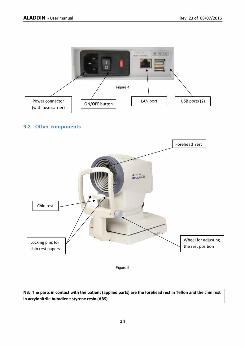
Figure 4
9.2 Other components
Figure 5
NB: The parts in contact with the patient (applied parts) are the forehead rest in Teflon and the chin rest
in acrylonitrile butadiene styrene resin (ABS)
ON/OFF button
Forehead rest
Chin rest
Locking pins for
chin rest papers
Wheel for adjusting
the rest position
USB ports (2) Power connector
(with fuse carrier)
LAN port
ALADDIN - User manual Rev. 23 of 08/07/2016
25
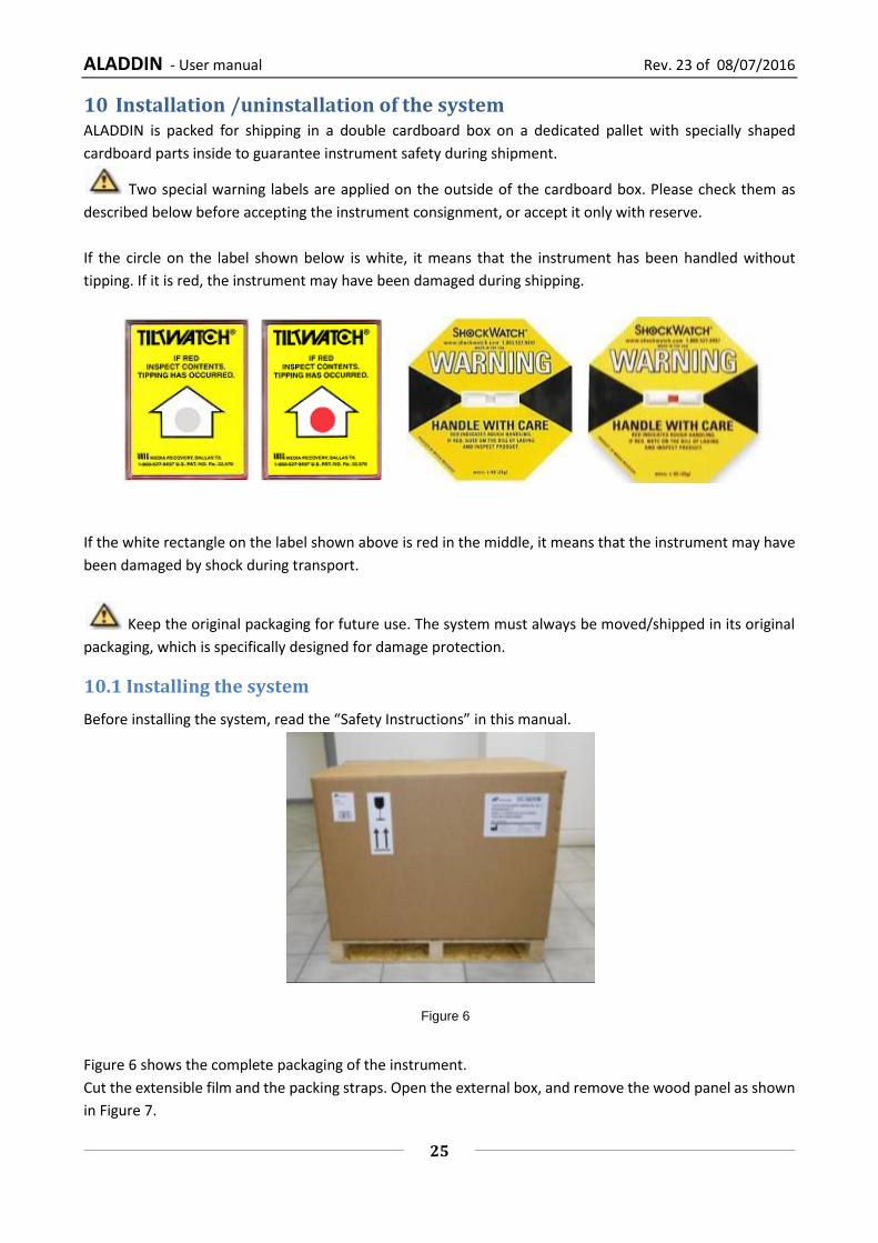
10 Installation /uninstallation of the system ALADDIN is packed for shipping in a double cardboard box on a dedicated pallet with specially shaped
cardboard parts inside to guarantee instrument safety during shipment.
Two special warning labels are applied on the outside of the cardboard box. Please check them as
described below before accepting the instrument consignment, or accept it only with reserve.
If the circle on the label shown below is white, it means that the instrument has been handled without
tipping. If it is red, the instrument may have been damaged during shipping.
If the white rectangle on the label shown above is red in the middle, it means that the instrument may have
been damaged by shock during transport.
Keep the original packaging for future use. The system must always be moved/shipped in its original
packaging, which is specifically designed for damage protection.
10.1 Installing the system
Before installing the system, read the “Safety Instructions” in this manual.
Figure 6 shows the complete packaging of the instrument.
Cut the extensible film and the packing straps. Open the external box, and remove the wood panel as shown
in Figure 7.
Figure 6

ALADDIN - User manual Rev. 23 of 08/07/2016
26
Figure 7
Remove the manual and the accessories from the dedicated spaces between the two pieces of cardboard
(see Figure 8).
Figure 8
The accessories are:
“Topcon” box:
o calibration checking device
o chin rest paper
o chin rest pins
o touchscreen pen
o silicon cloth
Power cable
“Topcon” ALADDIN dust cover
ALADDIN user manual
ALADDIN - User manual Rev. 23 of 08/07/2016
27
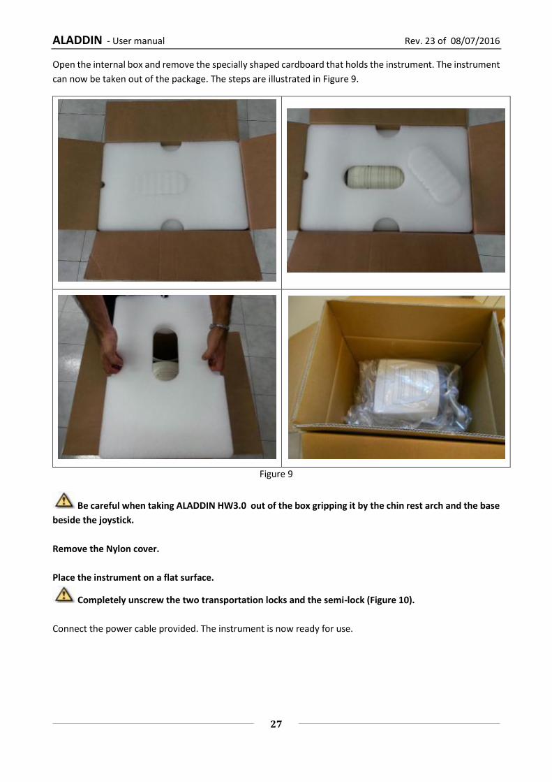
Open the internal box and remove the specially shaped cardboard that holds the instrument. The instrument
can now be taken out of the package. The steps are illustrated in Figure 9.
Figure 9
Be careful when taking ALADDIN HW3.0 out of the box gripping it by the chin rest arch and the base
beside the joystick.
Remove the Nylon cover.
Place the instrument on a flat surface.
Completely unscrew the two transportation locks and the semi-lock (Figure 10).
Connect the power cable provided. The instrument is now ready for use.
ALADDIN - User manual Rev. 23 of 08/07/2016
28
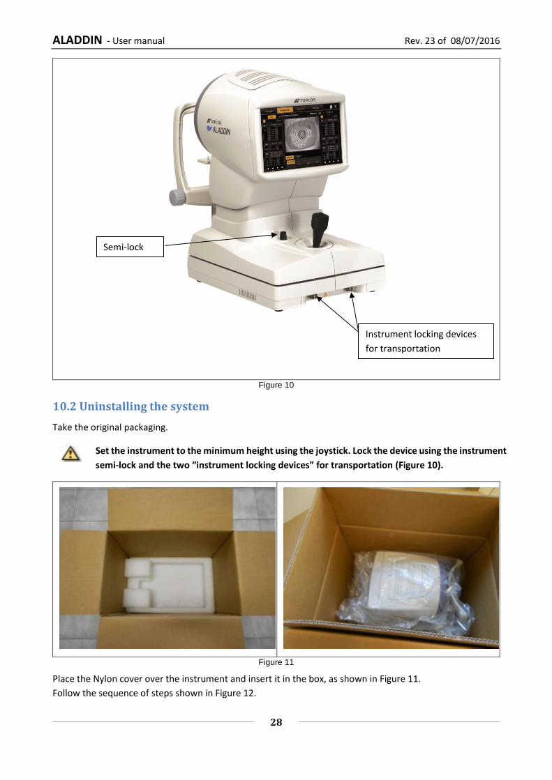
Figure 10
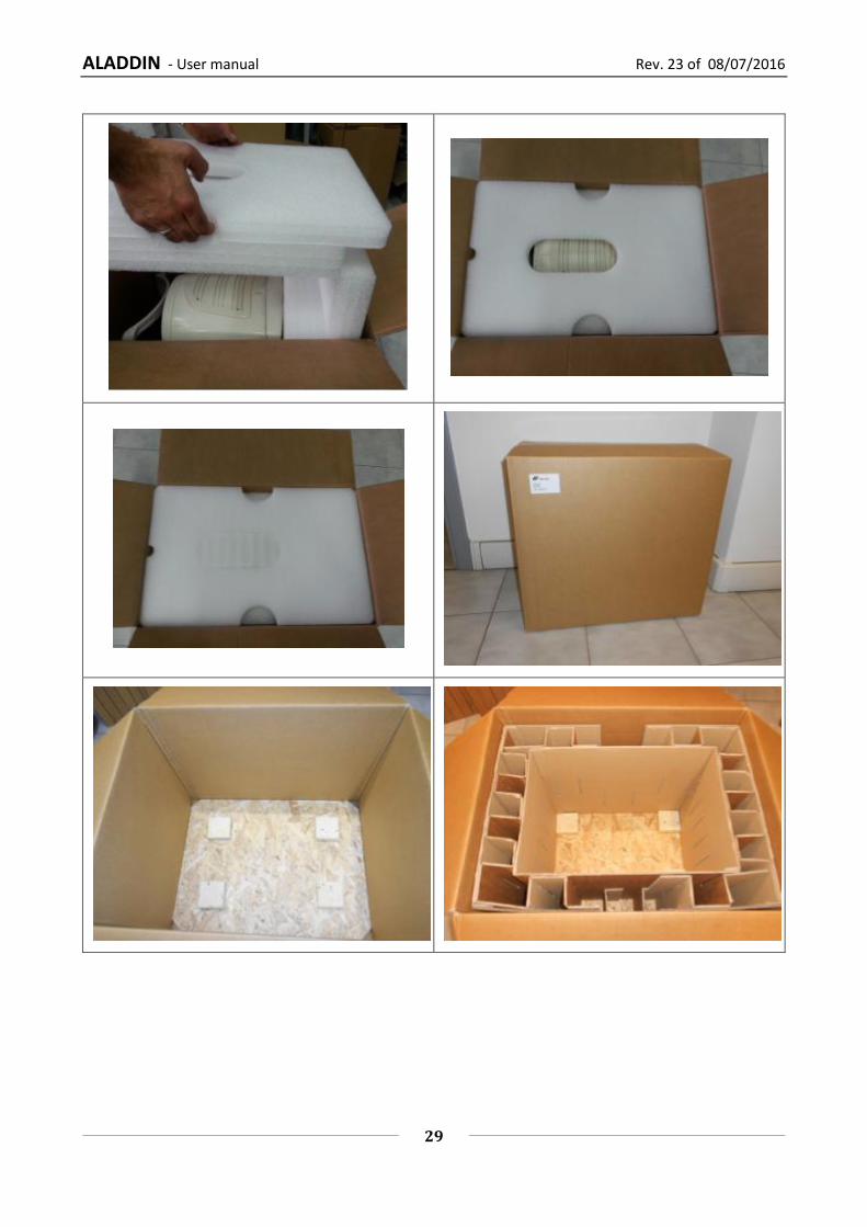
10.2 Uninstalling the system
Take the original packaging.
Set the instrument to the minimum height using the joystick. Lock the device using the instrument
semi-lock and the two “instrument locking devices” for transportation (Figure 10).
Figure 11
Place the Nylon cover over the instrument and insert it in the box, as shown in Figure 11.
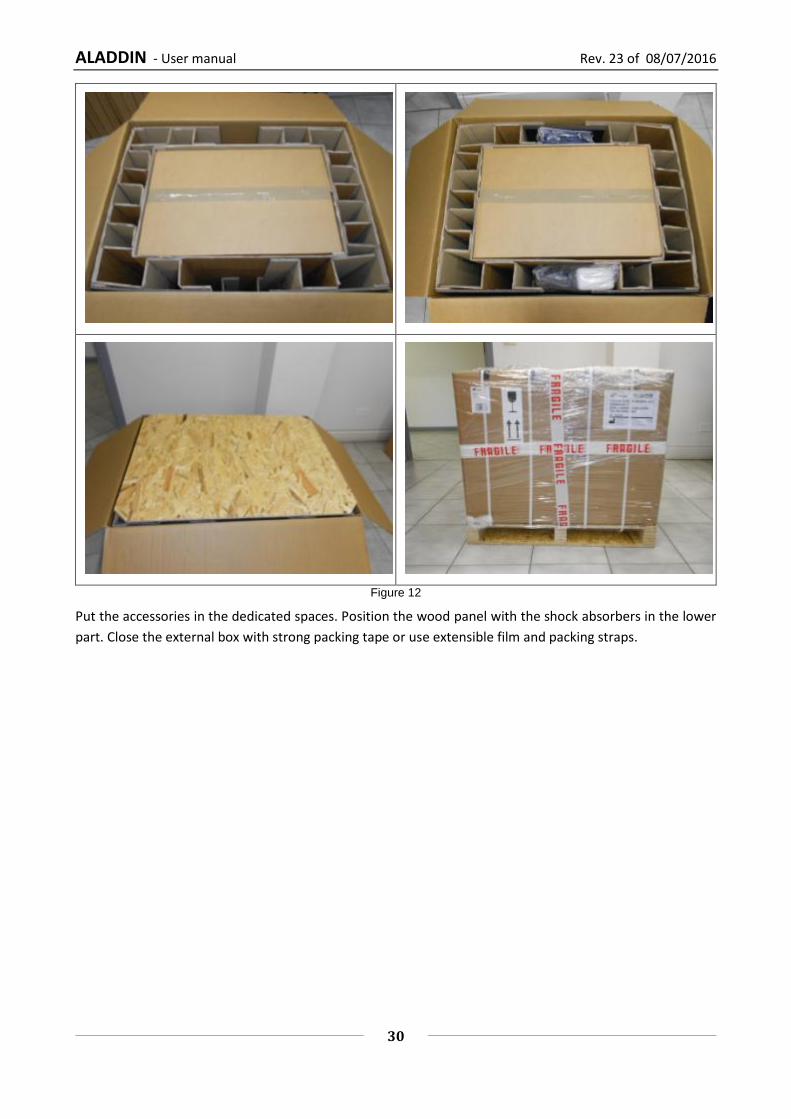
Follow the sequence of steps shown in Figure 12.
Semi-lock
Instrument locking devices
for transportation
ALADDIN - User manual Rev. 23 of 08/07/2016
29
ALADDIN - User manual Rev. 23 of 08/07/2016
30
Figure 12
Put the accessories in the dedicated spaces. Position the wood panel with the shock absorbers in the lower
part. Close the external box with strong packing tape or use extensible film and packing straps.

ALADDIN - User manual Rev. 23 of 08/07/2016
31
11 ALADDIN accessories and equipment
11.1 Standard equipment
Calibration checking device
The calibration checking device shows
the serial number of the instrument with
which it is associated. To properly check
calibration, the calibrator provided with the
instrument must always be used.
Power cable
Manual
Protective cover
Touchscreen pen
silicon cloth
chin rest paper
chin rest pins
ALADDIN - User manual Rev. 23 of 08/07/2016
32
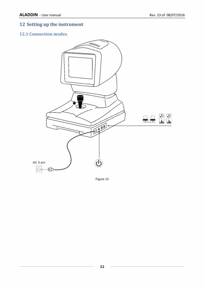
12 Setting up the instrument
12.1 Connection modes
Figure 13
ALADDIN - User manual Rev. 23 of 08/07/2016
33
13 OPERATING INSTRUCTIONS
ALADDIN is designed to work in stand-alone mode. For this reason, all the software functions are
automatically loaded when the device is turned on, enabling the user to control the device and guiding him
or her through the various phases:
- Entry of patient data
- Acquisition of the various possible modes
- Display of measurements
- Selection of intraocular lenses
More information for each function and the description of all the settings and other functions included is
provided in the following paragraphs of this chapter, to which we refer you for further details.
To interact with the software, the LCD display with touchscreen is used. To activate the button or the desired
function, simply touch the screen close to the command. The screen is highly sensitive. Minimum pressure is
required, indeed advised.
13.1 General description of functionalities
The Aladdin device has the following functionalities:
Cornea image acquisition and topographic analysis.
Measurement of the eye's axial length.
Measurement of the anterior chamber depth with the slit projection method.
White-to-White measurement.
Dynamic pupillometry acquisition: recording of a sequence of images of the pupil in varying light
conditions. Acquisition of the static pupillometry in controlled light conditions (photopic and
mesopic).
Analysis of the wavefront aberrations generated by the front surface of the cornea with Zernike
analysis: information on the cornea's optical properties and on the optical problems that can hinder
vision.
Intraocular lenses (IOL and Toric IOL) calculation, both BEFORE and AFTER refractive surgery (by
means of the Camellin-Calossi and Shammas No History formulae).
Refer to the literature related to the Camellin-Calossi formula (in case of specific questions please contact
Visia Imaging):
• Camellin-Calossi: M. Camellin, MD; A. Calossi, Optom “A new formula for intraocular lens power
calculation after refractive Corneal Surgery”, Journal of Refractive Surgery, vol. 22 Feb. 2006.
Refer to the literature related to the Shammas No History formula (in case of specific questions please contact
Visia Imaging):
• Shammas No-history: Shammas H.J., Shammas M.C:“No-history method of intraocular lens power calculation for cataract surgery after myopic laser in situ keratomileusis”, J Cataract Refract Surg 2007; 33:31–36 Q 2007 ASCRS and ESCRS.
ALADDIN - User manual Rev. 23 of 08/07/2016
34
• Shammas No-history: Shammas H.J., Shammas M.C., Garabet A., Kim J.H., Shammas A. , LaBree
L.: Correcting the Corneal Power Measurements for Intraocular Lens Power Calculations After
Myopic Laser In Situ Keratomileusis” - American Journal of Ophthalmology (Impact Factor: 4.02).
10/2003; 136(3):426-32.
• Shammas No-history: Shammas H.J., Shammas M.C., Hill W.E.:Intraocular lens power calculation
in eyes with previous hyperopic laser in situ keratomileusis” - J Cataract Refract Surg 2013;
39:739–744 Q 2013 ASCRS and ESCRS.
These formulae are for use in patients who have had prior refractive surgery. Each such patient is unique
and results may vary widely. You should interpret all IOL power recommendations with caution.
General instructions
On the various screens displayed by the software there are symbols that provide access to certain functions
available in several working environments.
Access to the "Settings" section, described in detail in the dedicated paragraph.
Direct printing of the report or saving a PDF file depending on the options selected in the print section.
13.2 Checking the calibration
The calibration must be checked when the device has been transported from one place to another
and when it has suffered an impact or thermal shocks.
Check the calibration of the device every day before starting patient examinations.
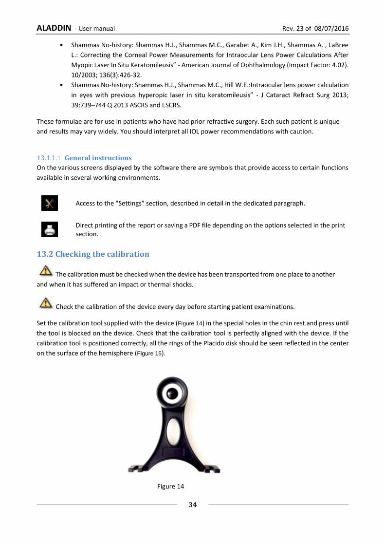
Set the calibration tool supplied with the device (Figure 14) in the special holes in the chin rest and press until
the tool is blocked on the device. Check that the calibration tool is perfectly aligned with the device. If the
calibration tool is positioned correctly, all the rings of the Placido disk should be seen reflected in the center
on the surface of the hemisphere (Figure 15).
Figure 14

ALADDIN - User manual Rev. 23 of 08/07/2016
35
CORRECT alignment
WRONG alignment
Figure 15
To check the calibration, turn on the instrument, and when asked to check the calibration, press Start (Figure 16) and then press Close (Figure 17).
Figure 16

ALADDIN - User manual Rev. 23 of 08/07/2016
36
Figure 17
To check the calibration, turn on the instrument and, when asked to check the calibration, press OK. By pressing ok, the test patient is automatically created. Now check and several times acquire the calibration checking device using the complete acquisition (AL-ACD-K), in check calibration is not possible to acquire the single measurements. If the calibration is ok, the “Valid” word will be display for all the three measurements (Figure 18).
ALADDIN - User manual Rev. 23 of 08/07/2016
37
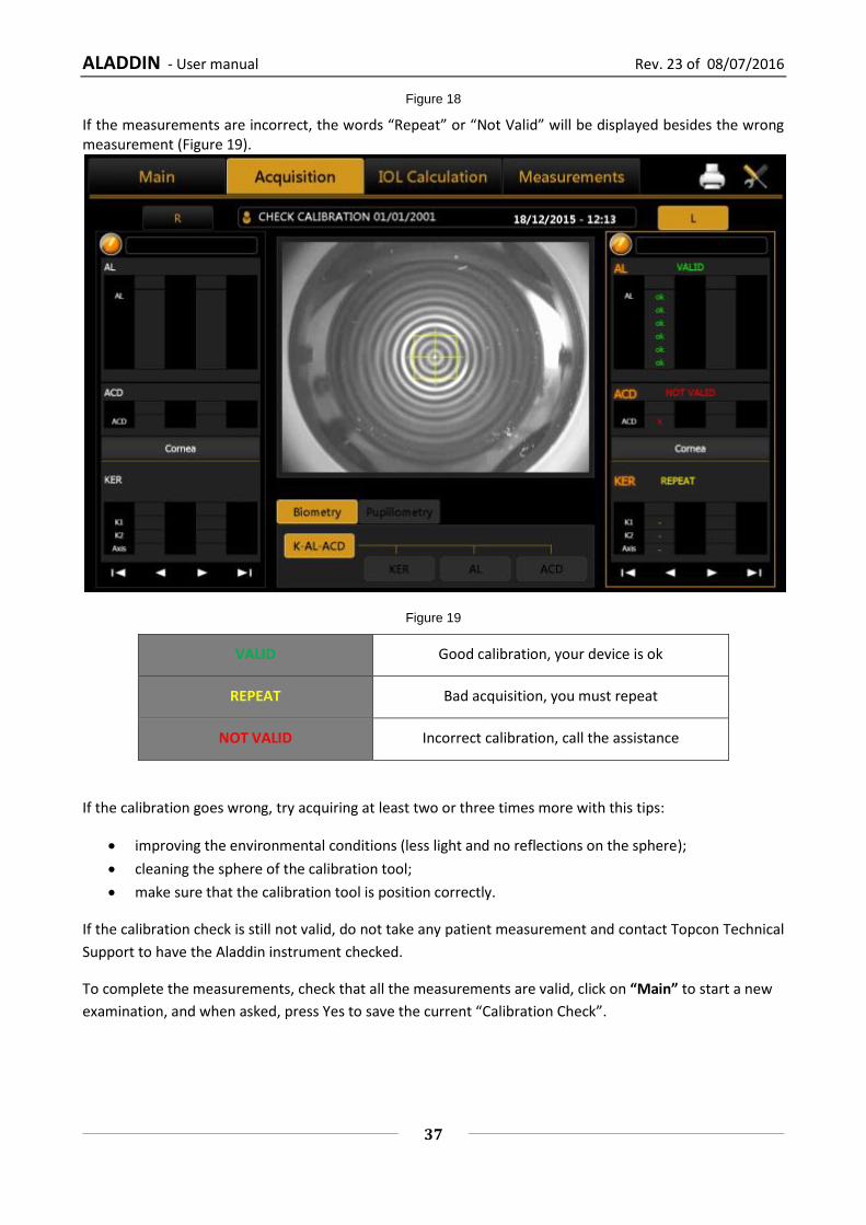
Figure 18
If the measurements are incorrect, the words “Repeat” or “Not Valid” will be displayed besides the wrong measurement (Figure 19).
Figure 19
VALID Good calibration, your device is ok
REPEAT Bad acquisition, you must repeat
NOT VALID Incorrect calibration, call the assistance
If the calibration goes wrong, try acquiring at least two or three times more with this tips:
improving the environmental conditions (less light and no reflections on the sphere);
cleaning the sphere of the calibration tool;
make sure that the calibration tool is position correctly.
If the calibration check is still not valid, do not take any patient measurement and contact Topcon Technical
Support to have the Aladdin instrument checked.
To complete the measurements, check that all the measurements are valid, click on “Main” to start a new
examination, and when asked, press Yes to save the current “Calibration Check”.

ALADDIN - User manual Rev. 23 of 08/07/2016
38
13.3 Patient entry/selection
When the instrument is turned on, the software displays the following screen. To continue the examination,
you always need to enter a patient or select one from those on file.
Figure 20
Figure 20 shows the section for creating a new patient, entering Last Name, Name and Birth Date as required
ALADDIN - User manual Rev. 23 of 08/07/2016
39
fields (Gender and ID are optional). You can set from the settings environment to have only the ID as required
field.
13.3.1 Creating a new patient
To create a new patient, select the “New” tab and enter the data using the on-screen keyboard. Once you
have entered the new patient data, click on the “Ok” button or select the “Acquisition” tab to confirm the
information and continue with the examination. If you want to empty all the fields click on the “Clear” button.
Before going into the acquisition environment, additional information on the patient is required, in particular
the presence and type of crystalline and the nature of the vitreous body (Figure 22).
An external keyboard or another input device compatible with “keyboard wedge interface” (PS/2) such as
barcode or card reader can be connected to the device to input text. The user must assure that the desired
textbox is under focus before the input action.
Before connecting an external device, such as a computer, printer, monitor, keyboard, mouse or other
devices, make sure that they comply with the EN 60950-1 standard and have the CE marking.
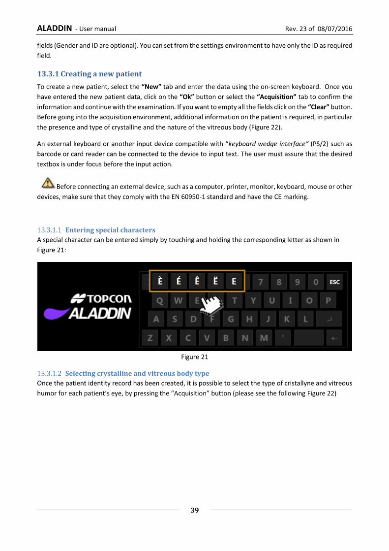
Entering special characters
A special character can be entered simply by touching and holding the corresponding letter as shown in
Figure 21:
Figure 21
Selecting crystalline and vitreous body type
Once the patient identity record has been created, it is possible to select the type of cristallyne and vitreous
humor for each patient’s eye, by pressing the “Acquisition” button (please see the following Figure 22)
ALADDIN - User manual Rev. 23 of 08/07/2016
40
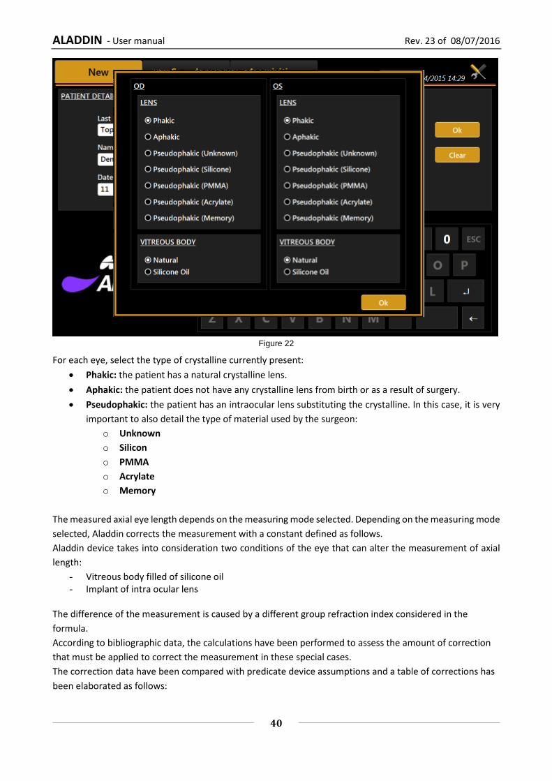
Figure 22
For each eye, select the type of crystalline currently present:
Phakic: the patient has a natural crystalline lens.
Aphakic: the patient does not have any crystalline lens from birth or as a result of surgery.
Pseudophakic: the patient has an intraocular lens substituting the crystalline. In this case, it is very
important to also detail the type of material used by the surgeon:
o Unknown
o Silicon
o PMMA
o Acrylate
o Memory
The measured axial eye length depends on the measuring mode selected. Depending on the measuring mode
selected, Aladdin corrects the measurement with a constant defined as follows.
Aladdin device takes into consideration two conditions of the eye that can alter the measurement of axial
length:
- Vitreous body filled of silicone oil - Implant of intra ocular lens
The difference of the measurement is caused by a different group refraction index considered in the
formula.
According to bibliographic data, the calculations have been performed to assess the amount of correction
that must be applied to correct the measurement in these special cases.
The correction data have been compared with predicate device assumptions and a table of corrections has
been elaborated as follows:

ALADDIN - User manual Rev. 23 of 08/07/2016
41
The correction values (in mm) of the natural vitreous body
Phakic 0
APhakic 0.21
Pseudophakic Unknown material 0.11
Pseudophakic Silicone IOL 0.12
Pseudophakic PMMA IOL 0.11
Pseudophakic Acrylic IOL 0.1
Pseudophakic Memory IOL 0.11
For the vitreous body you can choose between:
Natural: the vitreous body has never been operated or treated such as to alter its composition.
Silicon Oil: the vitreous body has been filled, even only partly, with silicon oil.
The correction values (in mm) of the vitreous body filled by Silicon Oil
Phakic -0.74
APhakic -0.86
Pseudophakic Unknown material -0.75
Pseudophakic Silicone IOL -0.74
Pseudophakic PMMA IOL -0.75
Pseudophakic Acrylic IOL -0.76
Pseudophakic Memory IOL -0.75
All this information is required because, on the basis of the artificial materials and their optical properties
present inside the eye, the instrument always corrects the measurements obtained to the most precise value
possible.
Once this information has been entered, you can access the acquisition environment.
For more details on the acquisition environment see the dedicated section.
The vitreous body nature is expressed, if different from natural, in the acquisition view as well as in the output
reports, as shown in the following figures. The lens nature is always reported.

ALADDIN - User manual Rev. 23 of 08/07/2016
42
ALADDIN - User manual Rev. 23 of 08/07/2016
43
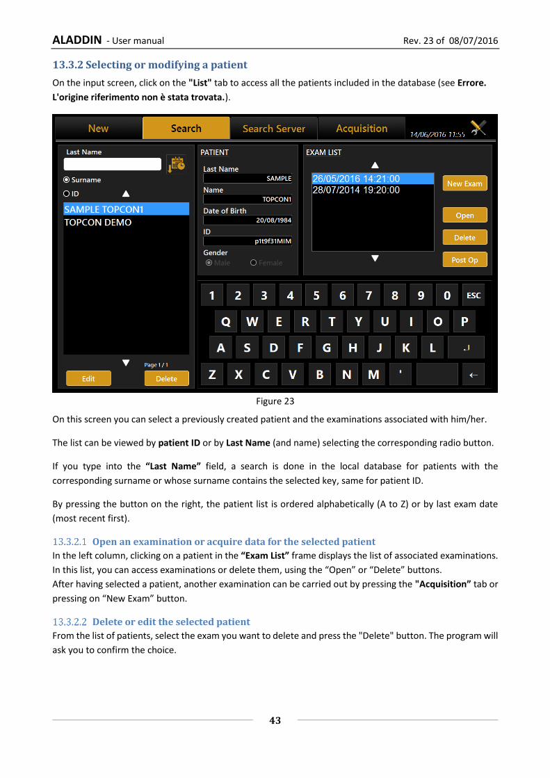
13.3.2 Selecting or modifying a patient
On the input screen, click on the "List" tab to access all the patients included in the database (see Errore.
L'origine riferimento non è stata trovata.).
Figure 23
On this screen you can select a previously created patient and the examinations associated with him/her.
The list can be viewed by patient ID or by Last Name (and name) selecting the corresponding radio button.
If you type into the “Last Name” field, a search is done in the local database for patients with the
corresponding surname or whose surname contains the selected key, same for patient ID.
By pressing the button on the right, the patient list is ordered alphabetically (A to Z) or by last exam date
(most recent first).
Open an examination or acquire data for the selected patient
In the left column, clicking on a patient in the “Exam List” frame displays the list of associated examinations.
In this list, you can access examinations or delete them, using the “Open” or “Delete” buttons.
After having selected a patient, another examination can be carried out by pressing the "Acquisition” tab or
pressing on “New Exam” button.
Delete or edit the selected patient
From the list of patients, select the exam you want to delete and press the "Delete" button. The program will
ask you to confirm the choice.
ALADDIN - User manual Rev. 23 of 08/07/2016
44
Press "Edit" to change the name, surname or date of birth. This takes you back to the initial "New" tab. From
here, you can edit the information you need to change and press “Ok” or “Cancel” to confirm or cancel the
changes.
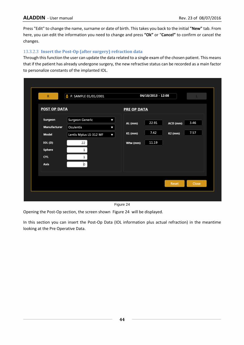
Insert the Post-Op (after surgery) refraction data
Through this function the user can update the data related to a single exam of the chosen patient. This means
that if the patient has already undergone surgery, the new refractive status can be recorded as a main factor
to personalize constants of the implanted IOL.
Figure 24
Opening the Post-Op section, the screen shown Figure 24 will be displayed.
In this section you can insert the Post-Op Data (IOL information plus actual refraction) in the meantime
looking at the Pre Operative Data.

ALADDIN - User manual Rev. 23 of 08/07/2016
45
13.3.3 Selecting a patient from Server
Once enabled, Aladdin IMAGEnet i-base’s integration from Aladdin’s settings panel (refer to IMAGEnet i-
base configuration), it’s possible to select a new patient from the patient list retrieved from IMAGEnet i-base
(Figure 25).
In the same way, Aladdin can be activated to search patients from DICOM services (refer to DICOM
configuration section):
DICOM Patient Root Query: search patient’s details on enable patient’s archive server
DICOM Modality Worklist: get the list of patients and tasks in the waiting room
The user can search for a patient either by surname, by id or by date of birth (i-base only). Will be created a
list of patients corresponding to the search criteria (Figure 27). Once selected a patient, the user can create
a new examination in the standard mode by clicking on the Acquisition or OK button button.
Figure 25
The user can search from IMAGEnet i-base and/or DICOM sources at the same time by enabling/disabling
the corresponding options using the server selection button.

ALADDIN - User manual Rev. 23 of 08/07/2016
46
Figure 26
Figure 27
ALADDIN - User manual Rev. 23 of 08/07/2016
47
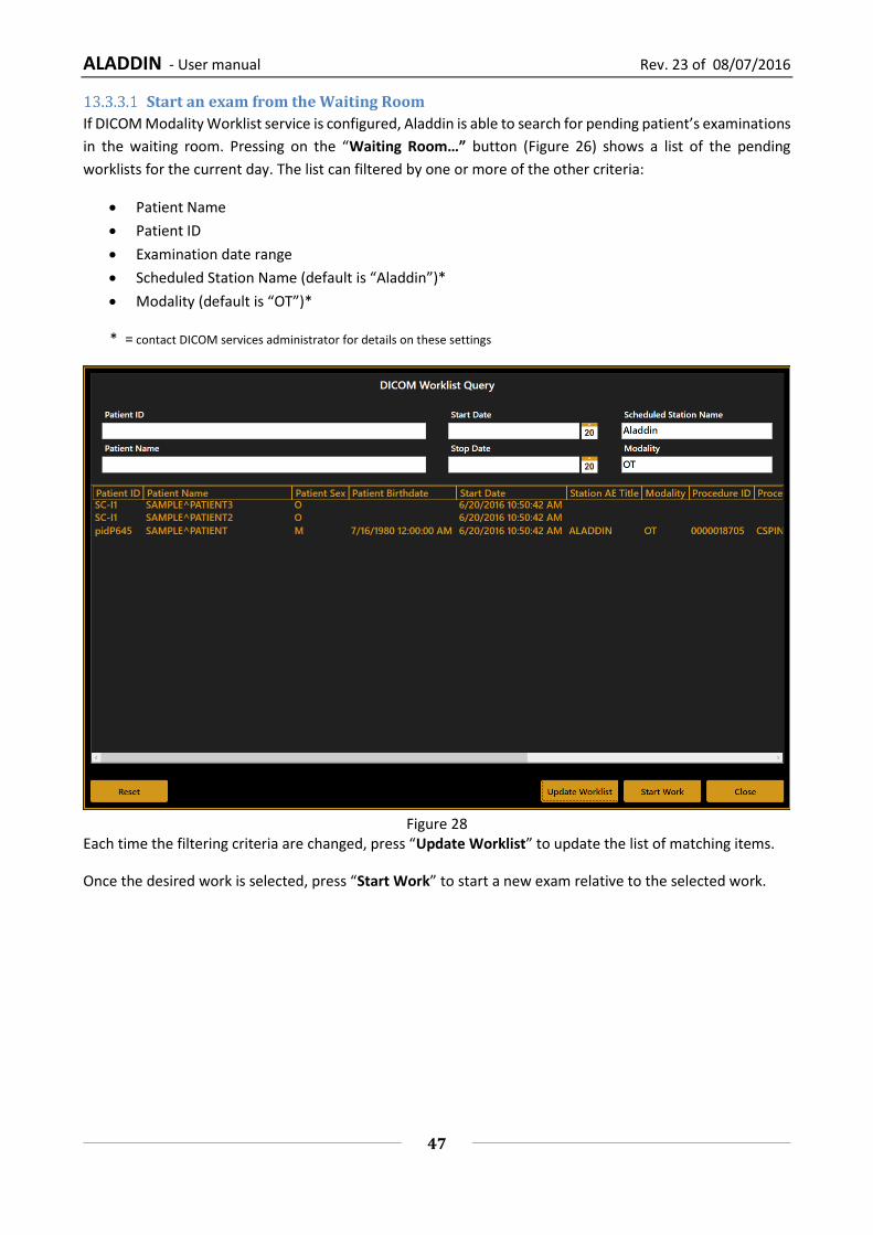
Start an exam from the Waiting Room
If DICOM Modality Worklist service is configured, Aladdin is able to search for pending patient’s examinations
in the waiting room. Pressing on the “Waiting Room…” button (Figure 26) shows a list of the pending
worklists for the current day. The list can filtered by one or more of the other criteria:
Patient Name
Patient ID
Examination date range
Scheduled Station Name (default is “Aladdin”)*
Modality (default is “OT”)*
* = contact DICOM services administrator for details on these settings
Figure 28
Each time the filtering criteria are changed, press “Update Worklist” to update the list of matching items.
Once the desired work is selected, press “Start Work” to start a new exam relative to the selected work.
ALADDIN - User manual Rev. 23 of 08/07/2016
48
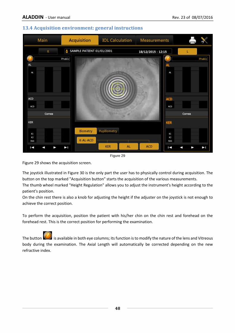
13.4 Acquisition environment: general instructions
Figure 29
Figure 29 shows the acquisition screen.
The joystick illustrated in Figure 30 is the only part the user has to physically control during acquisition. The
button on the top marked "Acquisition button" starts the acquisition of the various measurements.
The thumb wheel marked "Height Regulation" allows you to adjust the instrument's height according to the
patient's position.
On the chin rest there is also a knob for adjusting the height if the adjuster on the joystick is not enough to
achieve the correct position.
To perform the acquisition, position the patient with his/her chin on the chin rest and forehead on the
forehead rest. This is the correct position for performing the examination.
The button is available in both eye columns; its function is to modify the nature of the lens and Vitreous
body during the examination. The Axial Length will automatically be corrected depending on the new
refractive index.

ALADDIN - User manual Rev. 23 of 08/07/2016
49
Figure 30
Wheel for
adjusting the
chinrest height. The position of the chin rest
must be both comfortable and
correct, i.e. it must allow the
person performing the
measurement to center
correctly on the fixation LED.
Make sure the patient's forehead is well up against the forehead rest.

ALADDIN - User manual Rev. 23 of 08/07/2016
50
13.4.1 Description of the Acquisition screen
Figure 31
Figure 31 shows the acquisition screen from where all the operations to acquire the required measurements
are performed.
The acquisition window has the following commands:
OD and OS: indicate the eye being acquired (the one highlighted in yellow); they are normally selected automatically, depending on the position into which you move the instrument.
Biometry: gives access to the biometric measurement section
Pupillometry: gives access to the pupillometry section
The buttons at the bottom of the data frame for each eye serve to scroll the measurements, as some of these are hidden if more than four acquisitions are made per eye.
When the acquisition is done, and the eye is selected: the correctly acquired measurements are displayed in white and incorrect measurements are displayed in red. See Figure 32.
Description of results
For each Biometry and Keratometry result a dedicated section is present. In each section the total result is
shown together with the standard deviation between the single results (if more than one) and eventual
warning or error signs (described in the following section).
Single results:
one for each
acquisition
Standard
deviation of
single results Total Result
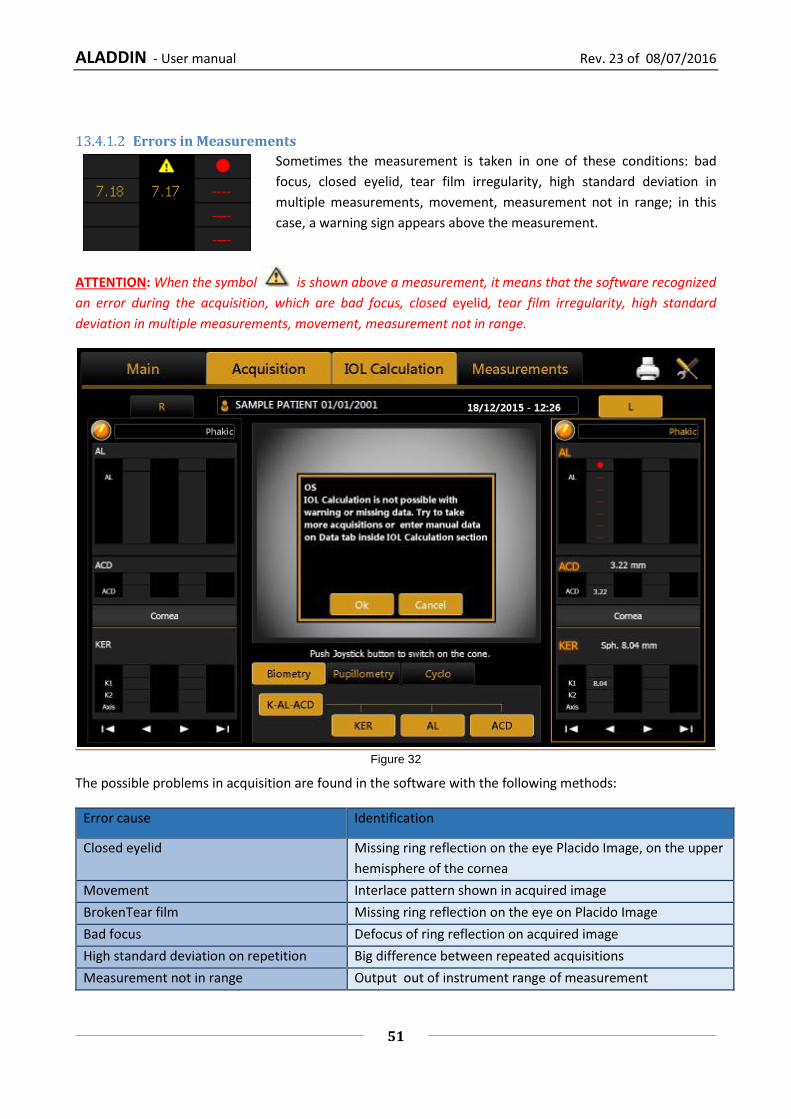
ALADDIN - User manual Rev. 23 of 08/07/2016
51
Errors in Measurements
Sometimes the measurement is taken in one of these conditions: bad
focus, closed eyelid, tear film irregularity, high standard deviation in
multiple measurements, movement, measurement not in range; in this
case, a warning sign appears above the measurement.
ATTENTION: When the symbol is shown above a measurement, it means that the software recognized
an error during the acquisition, which are bad focus, closed eyelid, tear film irregularity, high standard
deviation in multiple measurements, movement, measurement not in range.
Figure 32
The possible problems in acquisition are found in the software with the following methods:
Error cause Identification
Closed eyelid Missing ring reflection on the eye Placido Image, on the upper
hemisphere of the cornea
Movement Interlace pattern shown in acquired image
BrokenTear film Missing ring reflection on the eye on Placido Image
Bad focus Defocus of ring reflection on acquired image
High standard deviation on repetition Big difference between repeated acquisitions
Measurement not in range Output out of instrument range of measurement

ALADDIN - User manual Rev. 23 of 08/07/2016
52
If a warning sign is shown above a measurement, it is recommended to make further acquisitions until reliable data is obtained.
It is very important that the main types of measurement (KER-AL-ACD) taken are shown without a warning sign, otherwise it will not be possible to proceed to IOL Calculation with the current data
(valid ACD is needed only if using Haigis formula).
Caution should be practised when using the device’s ACD measurement for any given intraocular lens
calculation because of the high variability of this measurement.
The ACD measurement is the distance between the corneal epithelium and the crystalline lens surface. As shown in the figure above, accessing IOL Calculation, an error window will be shown warning the user to reacquire the measurements or to manually enter a new set of data. If the user proceeds manual input (Figure 33), the software will pre-populate all the fields with acquired data, even those with error or warning signs. . It is also possible to enter arbitrary data, if possible taken with other instruments.
Figure 33
Biometry
Selecting the "Biometry" button, you can perform the axial length, anterior chamber depth and keratometry
acquisitions either individually or in a full "AL-ACD-K" measurement, where the instrument executes all the
measurements in sequence, i.e.
Axial Length
Anterior Chamber Depth
Keratometry

ALADDIN - User manual Rev. 23 of 08/07/2016
53
To perform the measurements individually, simply click on one of the “AL” (axial length), “ACD” (anterior
chamber depth) or “KER” (keratometry) buttons.
WARNING: a correct ACD measurement cannot be made without acquiring the patient's
keratometry.
Caution should be practised when using the device’s ACD measurement for any given intraocular lens
calculation because of the high variability of this measurement.
The ACD measurement is the distance between corneal epithelium and the crystalline lens surface.
Pupillometry
Selecting the "Pupillometry" button gives access to the environment for the acquisition of the following
measurements:
Dynamic pupillometry
Photopic pupillometry
Mesopic pupillometry
13.5 Full biometry acquisition (K-AL-ACD)
Figure 34
This is a special mode which successively performs all the measurements described in detail in the following
paragraphs, specifically:
- Axial length measurement
- Anterior chamber depth

ALADDIN - User manual Rev. 23 of 08/07/2016
54
- Acquisition of the topographic map with all associated measurements
- Identification of Mesopic and Photopic pupil
13.5.1 Acquisition procedure
Backlighting of the Placido disk is automatically activated when you enter the acquisition environment. If the
instrument is not used for a few minutes, the cone turns off; to turn it on again, just press the joystick button.
To acquire the image or measurements in general, whatever mode you are in, simply proceed as follows:
1. Align the live image in the center and focus, then press the joystick button to start the acquisition. 2. Move the instrument forwards and backwards (following the indications of the red and blue arrows
on the screen) to find the ideal focus. While you find the ideal focus achieve the central alignment by centering the two squared aims with vertical or horizontal movements.
3. When the green indicators are displayed and the two squares are centered (both green), press the joystick button again and the system will automatically capture the required image and/or measurements.
4. Don’t move the joystick in the few seconds during the acquisition.
Focusing and centering guidance system is composed of two aspects:
Centering
Focusing distance Centering ideal conditions are achieved by centering the two squared aims by means of horizontal and vertical movements. The squared aims are the following:
Ideal Centering Marker, represents the ideal axis of alignment, matching the center of rings in the Placido image of the eye
Current Centering Marker, represents the current axis of alignment , matching the center of the viewport
The two squares assume different colors depending on two aspects: focusing position and centering in tolerance. Focusing ideal conditions are achieved by following the 4 indicators at the corners of the viewport, which explain the needed movement in the “forward/backward” direction.
The red arrows indicate to move the instrument forwards towards the patient's eye. In this situation the centering aims assume different tones of red color, as follows:
The centering condition is out of tolerance (Ideal Centering Marker and Current Centering Marker have different tones)
The centering condition is in tolerance (Ideal Centering Marker and Current Centering Marker have the same tone)

ALADDIN - User manual Rev. 23 of 08/07/2016
55
The blue arrows indicate to move the instrument backwards away from the patient. In this situation the centering aims assume different tones of blue color, as follows:
The centering condition is out of tolerance(Ideal Centering Marker and Current Centering Marker have different tones)
The centering condition is in tolerance (Ideal Centering Marker and Current Centering Marker have the same tone)
The green icons indicate that the ideal focus has been reached. Press the joystick button to start the automatic acquisition procedure. In this situation the centering aims assume different colors, as follows:
The centering condition is out of tolerance (Ideal Centering Marker is orange and Current Centering Marker is yellow)
The centering condition is in tolerance (Ideal Centering Marker and Current Centering Marker are both green)
During the acquisition procedure, pulsating signals appear above the “KER”, “AL” and “ACD” buttons to guide you through the several acquisition steps. They are explained in the following table.
The system is waiting for the user click on acquisition button. Follow the guide for right centering and focusing, then click the joystick.
The system is acquiring. Wait until it has finished.
The system has finished the acquiring procedure.
The system is acquiring or waiting for user input in a previous step of the acquisition sequence.
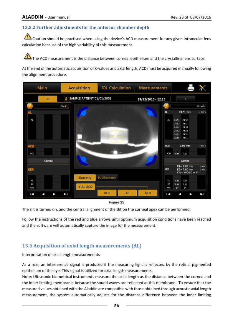
ALADDIN - User manual Rev. 23 of 08/07/2016
56
13.5.2 Further adjustments for the anterior chamber depth
Caution should be practised when using the device’s ACD measurement for any given intraocular lens
calculation because of the high variability of this measurement.
The ACD measurement is the distance between corneal epithelium and the crystalline lens surface.
At the end of the automatic acquisition of K-values and axial length, ACD must be acquired manually following
the alignment procedure.
Figure 35
The slit is turned on, and the central alignment of the slit on the corneal apex can be performed.
Follow the instructions of the red and blue arrows until optimum acquisition conditions have been reached
and the software will automatically capture the image for the measurement.
13.6 Acquisition of axial length measurements (AL)
Interpretation of axial length measurements
As a rule, an interference signal is produced if the measuring light is reflected by the retinal pigmented
epithelium of the eye. This signal is utilized for axial length measurements.
Note: Ultrasonic biometrical instruments measure the axial length as the distance between the cornea and
the inner limiting membrane, because the sound waves are reflected at this membrane. To ensure that the
measured values obtained with the Aladdin are compatible with those obtained through acoustic axial length
measurement, the system automatically adjusts for the distance difference between the inner limiting

ALADDIN - User manual Rev. 23 of 08/07/2016
57
membrane and the pigmented epithelium. The displayed axial length values are thus directly comparable to
those obtained by immersion ultrasound, and no re-calculation or correction factors are necessary.
Deviations may nevertheless occur between the displayed axial lengths and ultrasonic readings (particularly
in the applanation procedure).
By selecting this mode, the acquisition environment shown in Figure 36 appears.
Figure 36
The side columns show the measurements performed for the two eyes (OD = right, OS = left).
For each acquisition, six measurements of the axial length are performed.
The information displayed is the same as in “K-AL-ACD” acquisition.
13.7 Acquisition of the anterior chamber measurement (ACD)
The anterior chamber depth may only be measured on phakic eyes! ACD measurements of
pseudophakic eyes result in measuring errors and/or incorrect readings. The readings for pseudophakic
eyes do not reflect the anterior chamber depth.
The keratometer measurement must be performed before anterior chamber depth measurement.
Caution should be practised when using the device’s ACD measurement for any given intraocular lens
calculation because of the high variability of this measurement.
The ACD measurement is the distance between corneal epithelium and the crystalline lens surface.
Fine adjust the device, so that:
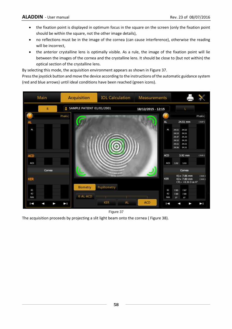
ALADDIN - User manual Rev. 23 of 08/07/2016
58
the fixation point is displayed in optimum focus in the square on the screen (only the fixation point
should be within the square, not the other image details),
no reflections must be in the image of the cornea (can cause interference), otherwise the reading
will be incorrect,
the anterior crystalline lens is optimally visible. As a rule, the image of the fixation point will lie
between the images of the cornea and the crystalline lens. It should be close to (but not within) the
optical section of the crystalline lens.
By selecting this mode, the acquisition environment appears as shown in Figure 37.
Press the joystick button and move the device according to the instructions of the automatic guidance system
(red and blue arrows) until ideal conditions have been reached (green icons).
Figure 37
The acquisition proceeds by projecting a slit light beam onto the cornea ( Figure 38).

ALADDIN - User manual Rev. 23 of 08/07/2016
59
Figure 38
Follow the instructions of the red and blue arrows until optimum acquisition conditions have been reached
and the software will automatically capture the image for the measurement.
In these conditions, the instrument records the anterior chamber depth.
13.8 Keratometry acquisition (KER)
Keratometry is used to measure the corneal curvature. It is based on the reflection of the Placido disk on the
eye at a controlled working distance for high measurement precision.
Aladdin allows the user to acquire the corneal topography of the eye. The “Corneal Map” is obtained from
the reflection of 24 rings of the Placido disk at a distance of 80 millimeters from the patient's eye. The position
of the device, in relation to the patient’s eye thus found, serves as a starting point for fine adjustments to be
made in the respective measurement mode.
By selecting this mode, the acquisition environment shown in Figure 39 appears.
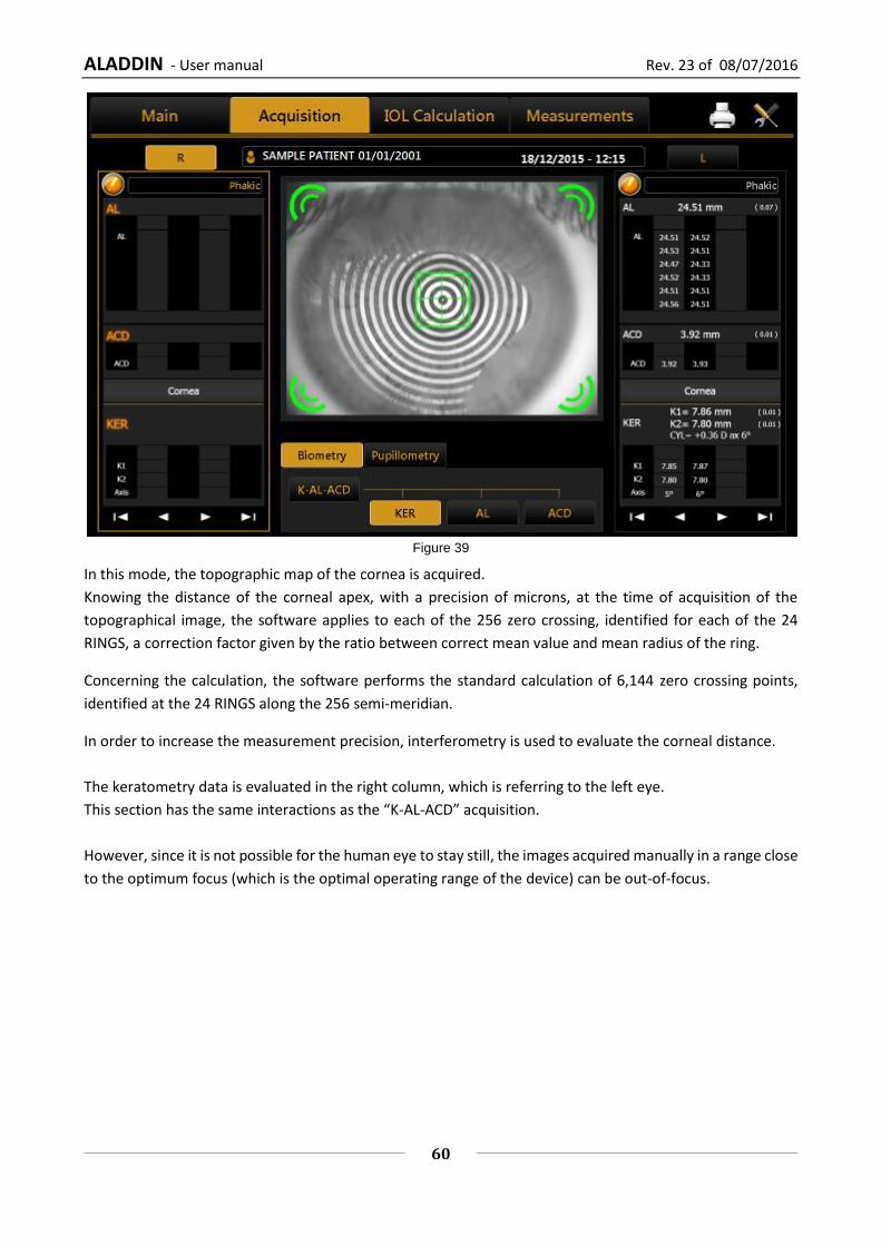
ALADDIN - User manual Rev. 23 of 08/07/2016
60
Figure 39
In this mode, the topographic map of the cornea is acquired.
Knowing the distance of the corneal apex, with a precision of microns, at the time of acquisition of the
topographical image, the software applies to each of the 256 zero crossing, identified for each of the 24
RINGS, a correction factor given by the ratio between correct mean value and mean radius of the ring.
Concerning the calculation, the software performs the standard calculation of 6,144 zero crossing points,
identified at the 24 RINGS along the 256 semi-meridian.
In order to increase the measurement precision, interferometry is used to evaluate the corneal distance.
The keratometry data is evaluated in the right column, which is referring to the left eye.
This section has the same interactions as the “K-AL-ACD” acquisition.
However, since it is not possible for the human eye to stay still, the images acquired manually in a range close
to the optimum focus (which is the optimal operating range of the device) can be out-of-focus.
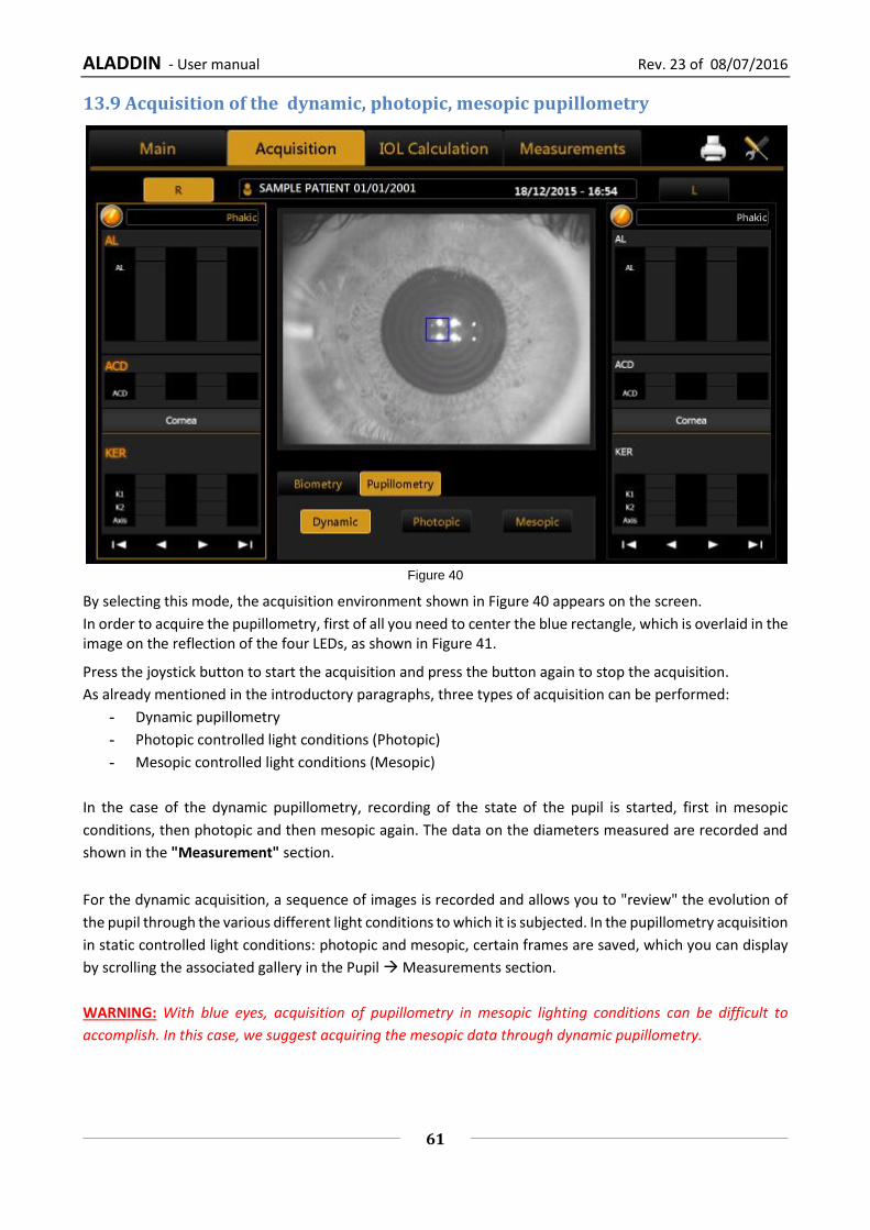
ALADDIN - User manual Rev. 23 of 08/07/2016
61
13.9 Acquisition of the dynamic, photopic, mesopic pupillometry
Figure 40
By selecting this mode, the acquisition environment shown in Figure 40 appears on the screen.
In order to acquire the pupillometry, first of all you need to center the blue rectangle, which is overlaid in the image on the reflection of the four LEDs, as shown in Figure 41.
Press the joystick button to start the acquisition and press the button again to stop the acquisition.
As already mentioned in the introductory paragraphs, three types of acquisition can be performed:
- Dynamic pupillometry
- Photopic controlled light conditions (Photopic)
- Mesopic controlled light conditions (Mesopic)
In the case of the dynamic pupillometry, recording of the state of the pupil is started, first in mesopic
conditions, then photopic and then mesopic again. The data on the diameters measured are recorded and
shown in the "Measurement" section.
For the dynamic acquisition, a sequence of images is recorded and allows you to "review" the evolution of
the pupil through the various different light conditions to which it is subjected. In the pupillometry acquisition
in static controlled light conditions: photopic and mesopic, certain frames are saved, which you can display
by scrolling the associated gallery in the Pupil Measurements section.
WARNING: With blue eyes, acquisition of pupillometry in mesopic lighting conditions can be difficult to
accomplish. In this case, we suggest acquiring the mesopic data through dynamic pupillometry.

ALADDIN - User manual Rev. 23 of 08/07/2016
62
Figure 41
Acquisition in photopic controlled light conditions
Acquisition in mesopic controlled light conditions
Figure 42

ALADDIN - User manual Rev. 23 of 08/07/2016
63
13.10 Report printing
After every measurement, you can print the corresponding report or print all the measurements made in the
current exam. In the top-right corner of the screen, press on the button.
As shown in Figure 43 you can now select from the left column which report to print and also with which
surgeon preset (from the “Surgeon” box).
You can print directly to an external printer or a USB drive and also print to both simultaneously.
Figure 43
In addition to these two options you can select a network folder as destination of report to print. For network
folder settings, see 13.15.5.1.
The “Aladdin Report Options” allow to define which overlay will be printed in the topography maps images
of the “Aladdin”. Refer to sections 13.13.1 and to 13.15.2 for details about this options.
By clicking on the Screenshot button (Figure 43) you can open the print screen preview and, as shown in
Figure 44, send to print the document as represented in the preview.

ALADDIN - User manual Rev. 23 of 08/07/2016
64
Figure 44
13.10.1 Available Printers
The printing form is showing a list of available printers. The available printers are the one installed on the
Operating System. Refer to “Appendix: Installing an external printer” or ask to your technical support in
order to have the desired printer installed.
The application pre-selects always the last used printer.
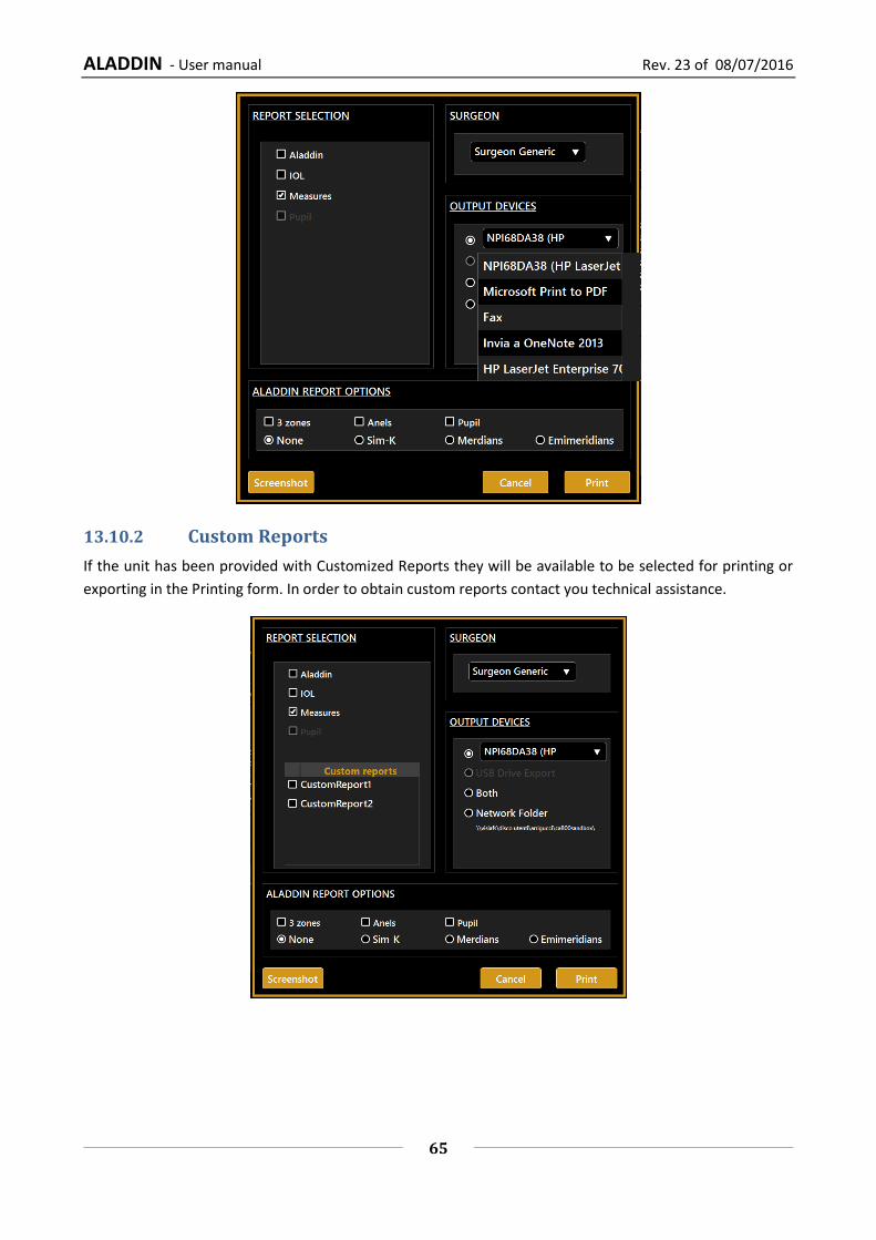
ALADDIN - User manual Rev. 23 of 08/07/2016
65
13.10.2 Custom Reports
If the unit has been provided with Customized Reports they will be available to be selected for printing or
exporting in the Printing form. In order to obtain custom reports contact you technical assistance.
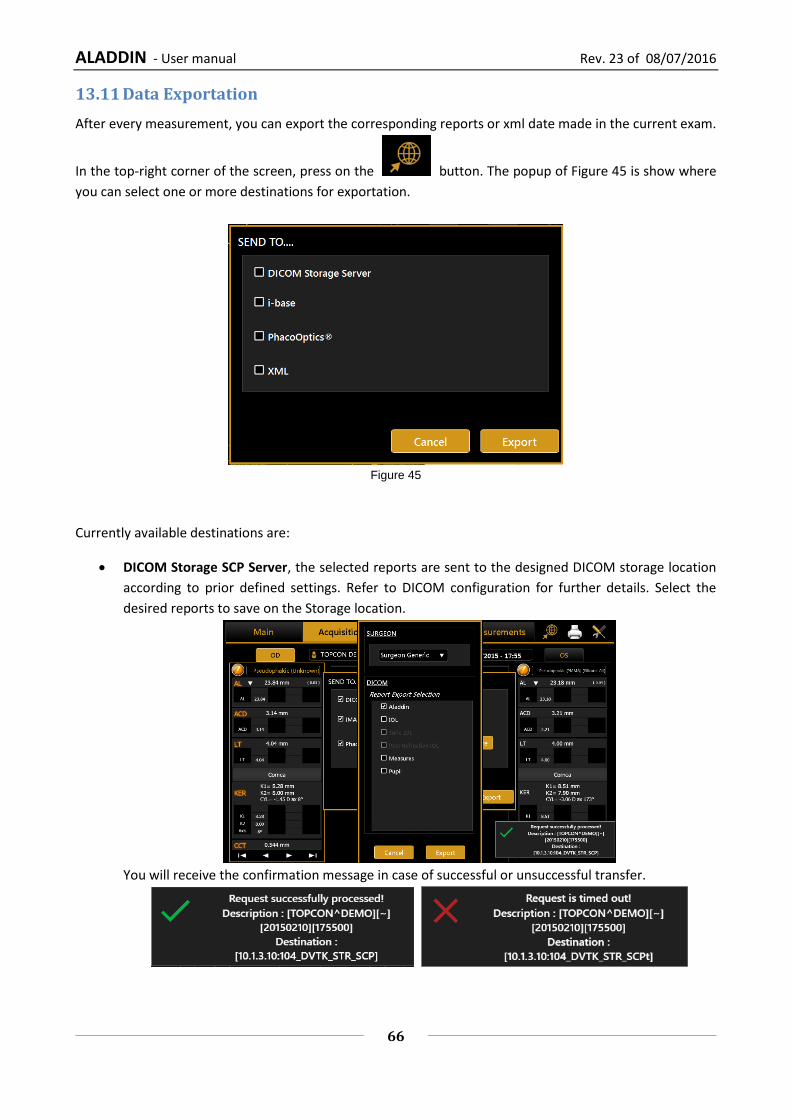
ALADDIN - User manual Rev. 23 of 08/07/2016
66
13.11 Data Exportation
After every measurement, you can export the corresponding reports or xml date made in the current exam.
In the top-right corner of the screen, press on the button. The popup of Figure 45 is show where
you can select one or more destinations for exportation.
Figure 45
Currently available destinations are:
DICOM Storage SCP Server, the selected reports are sent to the designed DICOM storage location
according to prior defined settings. Refer to DICOM configuration for further details. Select the
desired reports to save on the Storage location.
You will receive the confirmation message in case of successful or unsuccessful transfer.

ALADDIN - User manual Rev. 23 of 08/07/2016
67
If Storage Commitment is configured you will receive the confirmation message in case of successful
or unsuccessful transfer.
IMAGEnet 6/IMAGEnet i-base, the selected reports and data are sent to IMAGEnet i-base or
IMAGEnet 6 if activated and configured from the settings. If both are enabled the destination is
IMAGEnet 6.
PhacoOptics®: http://www.phacooptics.net/, export biometry data in xml format to a network
shared folder, to be imported in PhacoOptics® software. Refer to section 13.15.5 and to
PhacoOptics® software instruction for further details on configuration.
XML: create XML file with biometry data and IOL calculations (also images of the eye topography)
that is exported to the configured network shared folder. Refer to section 13.15.5.
When the selection of the destination you can press “Export” to perform exportation of data to the
destinations, or “Cancel” to just close.

ALADDIN - User manual Rev. 23 of 08/07/2016
68
13.12 IOL CALCULATION
ALADDIN also includes a section for calculation of the intraocular lenses (IOL Calculation).
In order to perform the intraocular lens power calculation, the available power interval, the increments and
the calculation constants must be provided for each type of formula and lens. These, however, do not depend
solely on the type of lens and the calculation formula, but are also closely linked to the measuring technology
and the surgical techniques used. It is strongly recommended that the user optimize the IOL constants in
clinical practice and the type of device used for acquisition of the biometric data.
Figure 46
The screen has various sections, which we will explore in detail below:
- Data
- IOL Calculation
- Toric IOL calculation
- Post Refractive IOL Calculation
Caution: The Toric IOL Calculation function is not available for the US market.
The first time a surgeon enters in IOL Calculation, it will appear the panel shown in Figure 47 that contains
the Disclaimer regarding the usage of the IOL Calculation. The Disclaimer will appear every time you enter
in IOL Calculation or you want to print a IOL report, unless you check the box below before clicking the OK
button. The Disclaimer is also replicated in the IOL settings (see 13.15.4.1), where you can even reactivate
its appearance at every IOL usage.

ALADDIN - User manual Rev. 23 of 08/07/2016
69
Figure 47
13.12.1 Data
In this section there is a summary of the measurements performed with the instrument.
The screen displayed for the “Data” tab is as shown in Figure 46. As you can see, it has two sections:
- Biometry: detailing the data on the ocular biometry
- Keratometry: detailing the patient's keratometric data
From the “Source” field (present in both the Biometry and Keratometry sections, Figure 46), you can choose
to use the measurements of the “Aladdin” instrument as source, or to enter them manually by pressing the
“Manual” button. In this case, a panel opens (Figure 48) where you can enter the data manually using the
numeric keypad.

ALADDIN - User manual Rev. 23 of 08/07/2016
70
Figure 48
In Figure 48 (Manual Keratometry tab), you can enter values both in Diopters or Millimeters. The values will
be automatically recognized according to a specific range. This range goes from 6.75mm to 9.64mm, (from
35Diopters to 50Diopters). Also every mm/D conversion from now on will be performed on the basis of the
current index in this section.
In Figure 48 you can manually enter biometry data; knowing that an external instrument does not always
work in Optical mode, you can also select acoustic measurement mode.
WARNING: The responsibility for any data entered and checked manually lies exclusively on the user.
WARNING: Using data from acoustic instruments also means that the constant of every IOL must be
optimized for those kinds of instrument; at present, it is more common to find online only databases
of lenses optimized for optical interferometry instruments.

ALADDIN - User manual Rev. 23 of 08/07/2016
71
13.12.2 Spherical IOL calculation
The section where you process the data collected for the calculation of the best intraocular lens is divided
into three main parts:
The IOL Calculation section is fundamental in calculating the total spherical power that will compensate the
removal of the crystalline in cataract surgery. This calculation, depending on the case, will be sufficiently
precise to guarantee the patient optimal vision.
In certain cases, however, if the corneal astigmatism exceeds a disturbance value, i.e. if faced with a medium
or medium-high astigmatism, it is advisable to implant an intraocular lens that also takes this factor into
account (refer to the following section).
In the “Toric IOL Calculation” section, a surgeon who has established, by means of a topography, the need
for an astigmatic correction, can confidently use the Oculentis toric lens calculation. The calculation is made
on the basis of the ideal spherical IOL and the patient's characteristics. The software then, on the basis of the
corneal astigmatism, recalculates the one on the IOL plane, also considering the possible astigmatism induced
by surgery.
The Toric IOL is thus chosen, which guarantees post-operation refraction with minimum residual
astigmatism.
Caution: The Toric IOL Calculation function is not available for the US market.
Finally, in the “Post Refractive IOL” section you can calculate the intraocular lenses for patients who have
already had refractive surgery to correct myopia or hypermetropia.
Figure 49

ALADDIN - User manual Rev. 23 of 08/07/2016
72
Figure 49 above shows the SW environment for entering data for the “IOL Calculation”.
In the “Surgeon” field, you can choose which surgeon will perform the IOL implant and any customization of
the constants or presetting of the preferred lenses and formulae will be applied on this basis.
In “Target” field the target refractive value for the Post-Op must be inserted.
The “Measurements” field summarizes the measurement data.
From the drop-down menu, select the IOL manufacturer and model, as well as the preferred formula with
which to calculate the best lens.
Once this data has been entered, the most appropriate lens can be chosen at the discretion of the surgeon.
The latter is highlighted in orange. Once selected, the lens will be memorized as the preferred one and will
be shown highlighted on the report printout.
Pressing “Reset” will reset the initial preset conditions.

ALADDIN - User manual Rev. 23 of 08/07/2016
73
13.12.3 Toric IOL calculation
Toric IOL calculation is divided into two main steps. The first one consists on the calculation of the Spherical
Equivalent Power; in the second one you can select the toric IOL that produce the best correction.
Caution: The Toric IOL Calculation function is not available for the US market.
Figure 50
Figure shows the first-step interface that has quite the same structure as the normal IOL calculation. The
available toric lenses you can select come from a list of models whose calculation constants have been
published by their manufacturer. The user can in case insert new toric manufacturers and/or models inside
toric IOL settings section (see 13.15.4.3).
In addition to choosing the “Target”, you need to specify also the “Surgical Induced Astigmatism (SIA)” and
“Incision Location (IL)”. The former identify the astigmatism (in diopters) induced by the incision while the
latter identify the surgical incision axis. After having selected the toric IOL model and one of the available
formulas, a values table from which to choose the Spherical Equivalent Power is obtained. Once you choose
a lens, pressing “Next” at the bottom right, you enter in the second-step of toric IOL calculation (Figure 48).

ALADDIN - User manual Rev. 23 of 08/07/2016
74
Figure 51
“Measures” and “Surgical Pre Op Data” frames summarize the values used in the first-step calculation.
“Expected Post Op Cornea” frame gives information about the post surgery patient eye Keratometry, taking
into account the aforementioned SIA and IL.
If the option “Abulafia-Koch correction” is selected the astigmatism is corrected in the “Expected Post Op
Cornea” by taking into account, together with SIA and IL, the nomogram-based correction. Refer to “Abulafia
A, Koch DD, Wang L, Hill WE, Assia EI, Franchina M, Barrett GD: New regression formula for toric intraocular
lens calculation. – Journal of Cataract & Refractive Surgery, 2016 – Elsevier”. If the Toric IOL calculation is
performed using the Abulafia-Koch Correction it is reported in the corresponding Toric IOL report.
As a result, the “Toric IOL” frame, immediately below, details the best toric lens computed automatically by
the system for the manufacturer and model selected previously in the first-step.
From “Available Toric Lenses” table you can choose also a different spherical and cylinder value for the lens,
based on the Residual Astigmatism you want to achieve (under-correction/overcorrection). In particular, the
best toric lens value is shown in the central row and (if available) the ones that under-correct above the
central row, the ones that overcorrect below.
At the right side, you can find an image that illustrates the ideal position of the IOL once the implant is in
place and in red the incision location angle.
Under the table, the small icon opens the Toric Rotation Misalignment Simulator (Figure 52).

ALADDIN - User manual Rev. 23 of 08/07/2016
75
Figure 52
This simulation shows the impact of a wrong axis placement that can occur during surgery and how it affects
the residual sphere and cylinder refraction of the patient. The simulator starts at the correct axis placement
and displays in the left bottom table a series of misalignment angles close to the ideal one. Selecting a
different row you can see the new residual sphere and cylinder at the selected axis.
In Figure 53 is shown the selection of a ten degrees misalignment, with the new axis selected in orange and
the correct one in green.
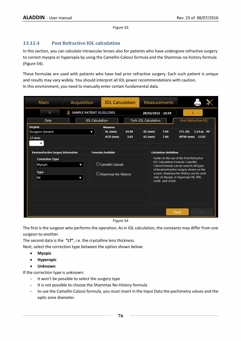
ALADDIN - User manual Rev. 23 of 08/07/2016
76
Figure 53
13.12.4 Post Refractive IOL calculation
In this section, you can calculate intraocular lenses also for patients who have undergone refractive surgery
to correct myopia or hyperopia by using the Camellin-Calossi formula and the Shammas no-history formula
(Figure 54).
These formulae are used with patients who have had prior refractive surgery. Each such patient is unique
and results may vary widely. You should interpret all IOL power recommendations with caution.
In this environment, you need to manually enter certain fundamental data.
Figure 54
The first is the surgeon who performs the operation. As in IOL calculation, the constants may differ from one
surgeon to another.
The second data is the "LT”, i.e. the crystalline lens thickness.
Next, select the correction type between the option shown below:
Myopic
Hyperopic
Unknown
If the correction type is unknown:
- it won’t be possible to select the surgery type
- It is not possible to choose the Shammas No-History formula
- to use the Camellin Calossi formula, you must insert in the Input Data the pachimetry values and the
optic zone diameter.

ALADDIN - User manual Rev. 23 of 08/07/2016
77
If the correction type is myopic or hyperopic, you have to select the surgery type performed on the patient
from those listed:
1. Radial Keratotomy (RK)
2. Photo Refractive Keratectomy (PRK)
3. Lasik
4. Lasek
5. LK
6. PTK
7. Unknown
In case of Radial Keratotomy, Photo Refractive Keratectomy, Lasik and Lasek you need to insert in the
“Refractive Change” frame the correct ametropia type and the correction factor obtained by the operation
( “SIRC”).
In case of LK, PTK or Unknown only the Camellin Calossi formula is available and you need to insert the
current Pachymetric data as well as the diameter of the optical zone to improve the accuracy of the final
calculation (Figure 55).
The Unknown option must be selected every time that you don’t know the type of surgery or one of the
associated information.
For example if you know your patient has undergone Radial Keratotomy or Photo Refractive Keratectomy or
Lasik or Lasek but you don’t know the SIRC value, select Unknown and insert the pachimetry values.
Figure 55
By pressing “Next” you move on to the final diagram of the calculation. Here you decide on the “Target” and
select the lens make and model.
If you highlight the lens selected, the result is memorized and highlighted on the report.
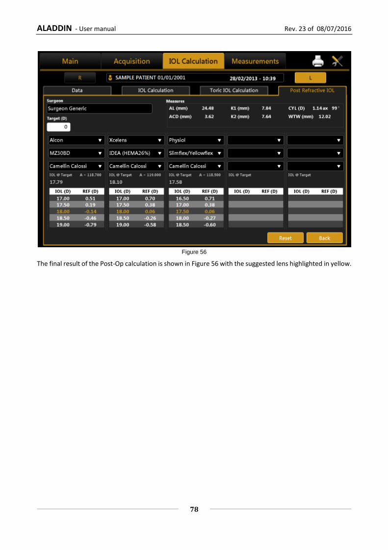
ALADDIN - User manual Rev. 23 of 08/07/2016
78
Figure 56
The final result of the Post-Op calculation is shown in Figure 56 with the suggested lens highlighted in yellow.

ALADDIN - User manual Rev. 23 of 08/07/2016
79
13.13 MEASUREMENTS
All measurements performed during the examination can be reviewed in detail in the "Measurements"
section.
There are four types of measurement.
- KER: Keratometry
o ZER: Zernike Analysis
- AL: Axial length
- ACD: Anterior chamber depth
- PUP: Pupillometry
to which various environments correspond, described in detail in the following sections.
13.13.1 TOPOGRAPHIC MAP (KER)
Figure 57
The environment displayed is shown in Figure 57.
Click on the “OD” or “OS” buttons to display the map of the right or left eye. The R and L buttons are only
active if the keratometry of the eye in question has been acquired.
In the right column, you can select the following options:
Axial or Tangential: axial map or tangential map
Absolute or Normalized: absolute scale or standardized scale
Eye, Map, Rings: to display the image of the eye, the map, the rings
Pressing on any point on the map displays the following information:
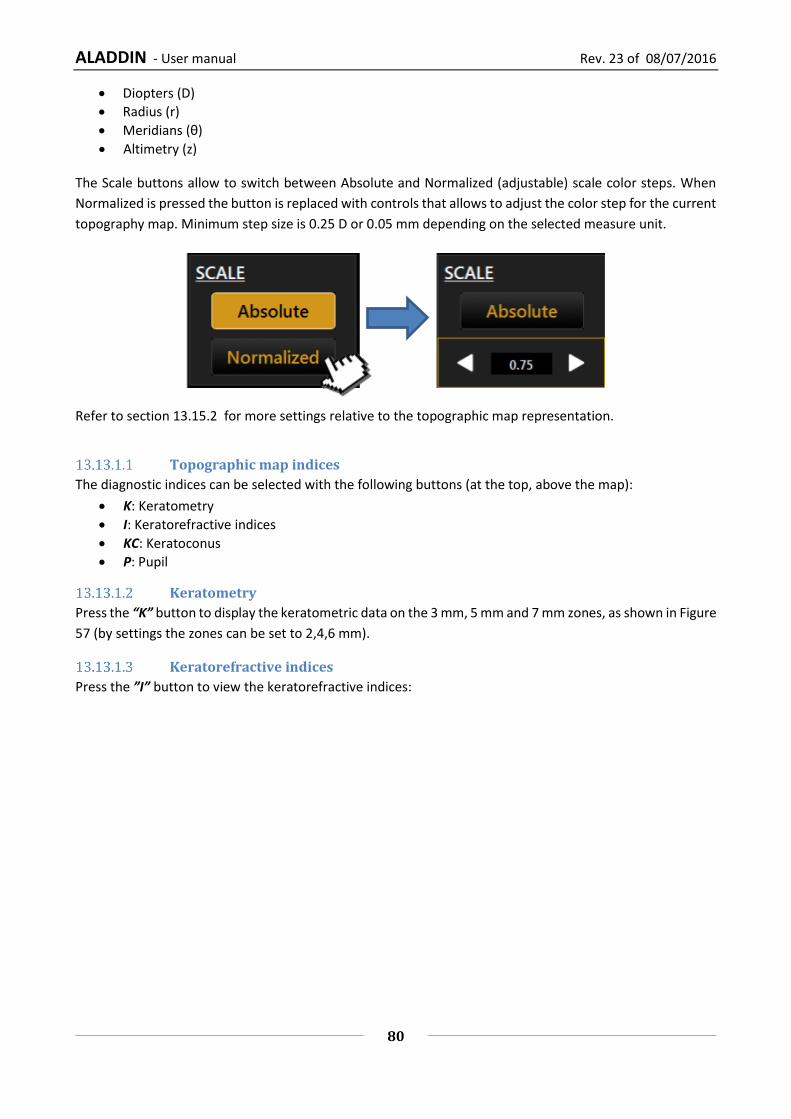
ALADDIN - User manual Rev. 23 of 08/07/2016
80
Diopters (D)
Radius (r)
Meridians (θ)
Altimetry (z)
The Scale buttons allow to switch between Absolute and Normalized (adjustable) scale color steps. When
Normalized is pressed the button is replaced with controls that allows to adjust the color step for the current
topography map. Minimum step size is 0.25 D or 0.05 mm depending on the selected measure unit.
Refer to section 13.15.2 for more settings relative to the topographic map representation.
Topographic map indices
The diagnostic indices can be selected with the following buttons (at the top, above the map):
K: Keratometry
I: Keratorefractive indices
KC: Keratoconus
P: Pupil
Keratometry
Press the “K” button to display the keratometric data on the 3 mm, 5 mm and 7 mm zones, as shown in Figure
57 (by settings the zones can be set to 2,4,6 mm).
Keratorefractive indices
Press the ”I” button to view the keratorefractive indices:

ALADDIN - User manual Rev. 23 of 08/07/2016
81
Figure 58
Astigmatism: Astigmatism at 3 and 5 mm (or 2 and 4 mm)
Pupil Avg: Average pupil power for a pupil of 4.5 mm
Asphericity: Asphericity of the cornea at 8 mm diameter
Spherical Aberration: Longitudinal spherical aberration of a 4.5mm diameter cornea area
Curvature Irregularity: Irregularity of curvature calculated on the standard deviation of the instantaneous readings for a 4.5mm diameter cornea area
Asymmetry + SAI: Asymmetry between the most curved hemisphere and the flattest one calculated for 4.5mm diameter cornea area and an SAI (Surface Asymmetry Index) that represents the surface asymmetry index of the 4.5mm diameter cornea area.
Keratoconus
Press the “KC” button to open Keratoconus screening with the following information:

ALADDIN - User manual Rev. 23 of 08/07/2016
82
Figure 59
AK: Apical curvature. Represents the power of the cornea in its apex
AGC: apical gradient of curvature. Represents the average variations per unit of length of the corneal power, taking the apical power as reference.
SI: difference between the average power of two circular zones centered in the vertical axis of the ruler and placed in the lower hemisphere and in the upper hemisphere of the cornea respectively.
Kpi: Keratoconus diagnosis probability index.
Based on the combined evaluation of the first three indices with the probability index, there are three
different possibilities: topographic picture not compatible with keratoconus (green); suspected keratoconus
(yellow); topographic picture compatible with keratoconus (red).
If the topographic picture is compatible with keratoconus or indicates a suspected keratoconus, the
numerical values of the geometric parameters of the cone are shown at the bottom of the panel. These are:
A: area of the keratoconus (mm²)
D: average diameter of the keratoconus (mm)
r, ø: polar coordinates (mm, °) of the barycentre of the keratoconus in relation to the centre of the map
RND: circularity factor of the keratoconus
Pupil
Press the “P” button to open the pupil's indices:

ALADDIN - User manual Rev. 23 of 08/07/2016
83
Figure 60
KC: KC represents the central keratometry in diopters
Avg Pupil Power: Average pupil power for a pupil of 4.5 mm and 3.0 mm
Photopic o Pupil Dec.: Pupil decentralization from optical axis o Avg Pupil Ø: Mean diameter of the pupil
Mesopic o Pup Dec.: Pupil decentralization from optical axis o Avg Pupil Ø: Mean diameter of the pupil

ALADDIN - User manual Rev. 23 of 08/07/2016
84
Profile
Press the "Profile" button to view the curvature profile along the most curved meridian and the flattest
meridian (red and blue).
The difference is displayed in green (Figure 61).
By pressing the arrow buttons, you can vary the flattest and the most curved meridians.
The graph will be modified accordingly.
Pressing the “Map” button, you go back to the topographic map.
Figure 61

ALADDIN - User manual Rev. 23 of 08/07/2016
85
13.13.2 Zernike
The Zernike module provides a comprehensive view of the wavefront aberrations generated by the front
surface of the cornea. The results of the Zernike axis are illustrated by means of numerical indices and graphic
representations (Figure 62).
Figure 62
Click on the “OD” or “OS” buttons to view the results of the Zernike analysis for the right or left eye.
On the left the OPD Map is detailed, representing the total aberration that corresponds to the sum of all the
aberration components and the RMS value. This allows you to quantify the deviation with respect to an ideal
wavefront.
On entering the module, the aberrations map is displayed ( “Maps” section):
Histograms of the Zernike expansion coefficients: each histogram represents the weight of the corresponding polynomial.
Primary aberrations map: Astigmatism: the map, the magnitude in diopters, the axis and the RMS value are displayed Spherical aberration: the map, the quantity of longitudinal spherical aberration in diopters
and the RMS value are displayed Coma: the map, the RMS value and the direction are displayed High Order: all the components of a higher order than the primaries are grouped; the map
and the RMS value are displayed.
Click on “Graphs” at the top left to display the vision quality summary (Figure 63).
This section displays:
Zernike Coefficient pyramid: represents the numerical value of each coefficient by means of a grey scale; the greater the coefficient, the greater the color contrast with the pyramid's background.
Point Spread Function: represents the intensity of the wavefront in the retina.

ALADDIN - User manual Rev. 23 of 08/07/2016
86
Spot Diagram: represents the spatial distribution of the wavefront over the retina.
Visus/Visus Low Contrast: represent the patient's real vision at high and low contrast.
Figure 63
The data displayed refers only to the component induced by the anterior surface of the cornea, not by the
eye's entire optical system.
Press the “Maps” button to return to the maps display.
The “Pupil” button opens a panel (Figure 64) where you can select the diameter of the pupil (in a range
between 2 mm and 7.5 mm) to see how the aberrations change with the variation of the pupil diameter.
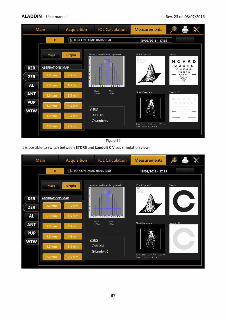
ALADDIN - User manual Rev. 23 of 08/07/2016
87
Figure 64
It is possible to switch between ETDRS and Landolt C Visus simulation view.
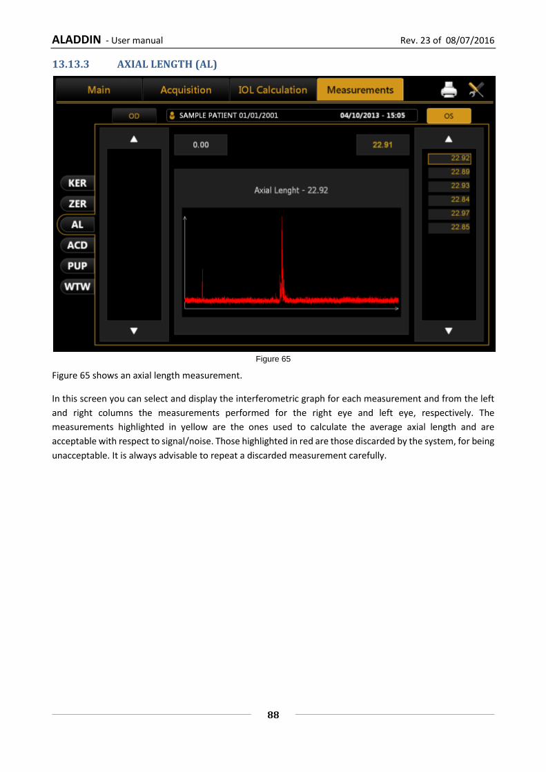
ALADDIN - User manual Rev. 23 of 08/07/2016
88
13.13.3 AXIAL LENGTH (AL)
Figure 65
Figure 65 shows an axial length measurement.
In this screen you can select and display the interferometric graph for each measurement and from the left
and right columns the measurements performed for the right eye and left eye, respectively. The
measurements highlighted in yellow are the ones used to calculate the average axial length and are
acceptable with respect to signal/noise. Those highlighted in red are those discarded by the system, for being
unacceptable. It is always advisable to repeat a discarded measurement carefully.
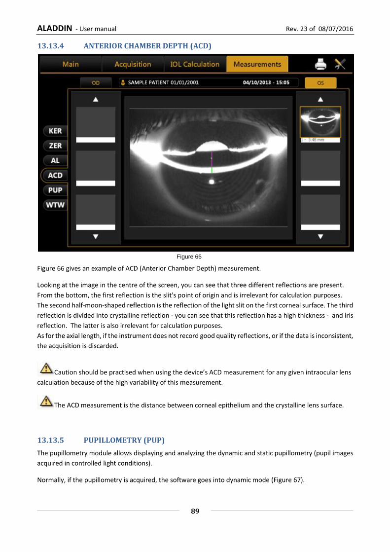
ALADDIN - User manual Rev. 23 of 08/07/2016
89
13.13.4 ANTERIOR CHAMBER DEPTH (ACD)
Figure 66
Figure 66 gives an example of ACD (Anterior Chamber Depth) measurement.
Looking at the image in the centre of the screen, you can see that three different reflections are present.
From the bottom, the first reflection is the slit's point of origin and is irrelevant for calculation purposes.
The second half-moon-shaped reflection is the reflection of the light slit on the first corneal surface. The third
reflection is divided into crystalline reflection - you can see that this reflection has a high thickness - and iris
reflection. The latter is also irrelevant for calculation purposes.
As for the axial length, if the instrument does not record good quality reflections, or if the data is inconsistent,
the acquisition is discarded.
Caution should be practised when using the device’s ACD measurement for any given intraocular lens
calculation because of the high variability of this measurement.
The ACD measurement is the distance between corneal epithelium and the crystalline lens surface.
13.13.5 PUPILLOMETRY (PUP)
The pupillometry module allows displaying and analyzing the dynamic and static pupillometry (pupil images
acquired in controlled light conditions).
Normally, if the pupillometry is acquired, the software goes into dynamic mode (Figure 67).

ALADDIN - User manual Rev. 23 of 08/07/2016
90
Figure 67
Click on “OD” or “OS” to display the pupillometry of the right or left eye, respectively.
With the patient's eye in view, buttons are located below the home screen. These buttons are used to
navigate between the acquired frames. The current frame is shown next to the buttons.
Display
Ring Center: Shows the position of the fixation point
Pupil: Shows the blue ring, which highlights the pupil's edges
Grid: Shows an overlaid grid
Rulers: Shows calibrated rulers
Sequences
The user can select the sequence of images to be displayed using the buttons at the top:
Dynamic
Photopic
Mesopic
The active buttons are those for which at least one acquisition is present.
Dynamic
Clicking on the "Dynamic" button to display the dynamic pupillometry in the left column, the following
information will also be displayed:
Average: Value of the maximum and minimum pupil diameter measured in all the images acquired during the sequence
Pupil Center: Cartesian coordinates of the average pupil center and its standard deviation

ALADDIN - User manual Rev. 23 of 08/07/2016
91
Diameter: Pupil diameter for the frame selected
Pupil Center (frame): Cartesian coordinates of the center of the pupil for the frame selected
Photopic, Mesopic
By clicking on the “Photopic”, “Mesopic” buttons static pupillometry acquisitions will be displayed, with the
following information:
Value of the average pupil diameter measured in all the images acquired during the sequence The other information is the same as that already described for the dynamic pupillometry.
Functions
Graphs
Pressing the “Graphs” button displays the graphs relating to the pupil. This function is explained in the next
paragraph.
Delete
Pressing the “Delete” button, the system cancels the current pupillometry frame and the data it contains.
Graphs
In this section three types of graph are displayed:
Decentralization (Figure 68)
Latency (Figure 69)
Statistics (Figure 70) In all these graphs you can select which eye you want to analyze by clicking on “OD” or “OS”.
The “Close” button closes the graphs.

ALADDIN - User manual Rev. 23 of 08/07/2016
92
Decentralization
Figure 68
The green concentric circles identify the decentralization of the pupil center with respect to the fixation point. The red dots, on the other hand, represent the coordinate variations during acquisition of the dynamic pupillometry.
Latency
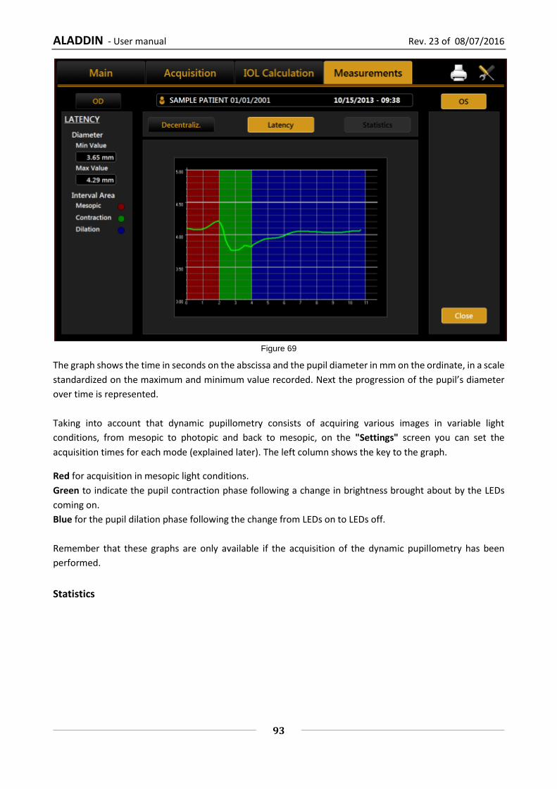
ALADDIN - User manual Rev. 23 of 08/07/2016
93
Figure 69
The graph shows the time in seconds on the abscissa and the pupil diameter in mm on the ordinate, in a scale
standardized on the maximum and minimum value recorded. Next the progression of the pupil’s diameter
over time is represented.
Taking into account that dynamic pupillometry consists of acquiring various images in variable light
conditions, from mesopic to photopic and back to mesopic, on the "Settings" screen you can set the
acquisition times for each mode (explained later). The left column shows the key to the graph.
Red for acquisition in mesopic light conditions.
Green to indicate the pupil contraction phase following a change in brightness brought about by the LEDs
coming on.
Blue for the pupil dilation phase following the change from LEDs on to LEDs off.
Remember that these graphs are only available if the acquisition of the dynamic pupillometry has been
performed.
Statistics

ALADDIN - User manual Rev. 23 of 08/07/2016
94
Figure 70
The graph represents the static value of the percentile of the sample for each acquisition in controlled light
conditions.
As indicated in the key on the right-hand side and by the values detailed on the left, the red line represents
the average value of the sample, the blue frame the value interval between the 25% and 75% percentiles,
the green line the value interval between the 10% and 90% percentiles, and the red circle the values outside
this interval.
The graph is displayed only if images of the pupil have been acquired in photopic or mesopic conditions.
13.13.6 WHITE TO WHITE
The White to White section allows you to view the value of the corneal diameter calculated from limbus.
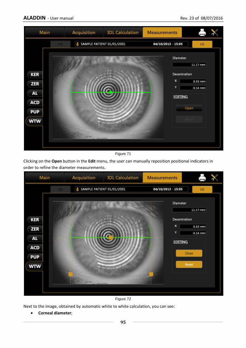
ALADDIN - User manual Rev. 23 of 08/07/2016
95
Figure 71
Clicking on the Open button in the Edit menu, the user can manually reposition positional indicators in
order to refine the diameter measurements.
Figure 72
Next to the image, obtained by automatic white to white calculation, you can see:
Corneal diameter;

ALADDIN - User manual Rev. 23 of 08/07/2016
96
Decentralisation: deviation from the center of the iris with respect to the fixation point.
By changing the indicators position also values of corneal diameter and offset of the visual axis x and y are
updated.
The Reset button restores all values to the ones obtained by the automatic calculations of system.

ALADDIN - User manual Rev. 23 of 08/07/2016
97
13.14 EXAMINATION DATA SAVING
After performing some acquisitions and eventual IOL calculations, in order to save the data from the examination, click on the home button. As shown in Figure 73, the software will ask the user to confirm the action.
Figure 73
If you want to save the data of the patients without doing an acquisition, you have to press the “main”
button when you are in the “acquisition” panel. The system will ask you if you want to save the current
patient’s details.

ALADDIN - User manual Rev. 23 of 08/07/2016
98
13.15 SETTINGS
To access the “Settings” section, press the button.
Figure 74
The settings screen is divided into the following categories.

ALADDIN - User manual Rev. 23 of 08/07/2016
99
General
Measurements
Surgeons
IOL
Report
Admin From each settings environment you can close and return to the previous activity by selecting the "Close" button.
13.15.1 General
Refer to Figure 74:
Language: The first time the program is started, the default language set is English and the keyboard layout
is "QWERTY".
To change the language settings, select the desired language from those that appear by clicking on the
button, press “Set” to set automatic start with the chosen language. It is suggested to reboot the device to
apply all the settings.
Keyboard Layout: To change the keyboard layout, select the desired layout and press "Set". You can display
the update of the layout in the personal details window ("Main").
Date: Choose the desired date format and press on the “Set” button. You can also set the current system
date and time by clicking on the “Edit” button.
Pointing Devices: Toggles the mouse cursor (on or off).
OD/OS Notation: Toggles between two different notations, OD/OS will show the Latin notation to indicate
which eye is being acquired. The native language will depend on the words for left and right.
Patient Required Fields: Toggles between two different options of required fields for creation of new
patient’s details. With ID only the ID is the only required field to insert when creating a patient. With this
option the patient list is by default shown by ID (can be changed to Surname and Name in the patient list
view).
13.15.2 Measurements
The acquisition settings panel allows you to set parameters for display of the corneal map, the printout and
acquisition and display of the pupillometry (Errore. L'origine riferimento non è stata trovata.).
Scales
Type
Select a map type:
Axial
Tangential
Scales
Select a scale measure:
Diopters
Millimeters
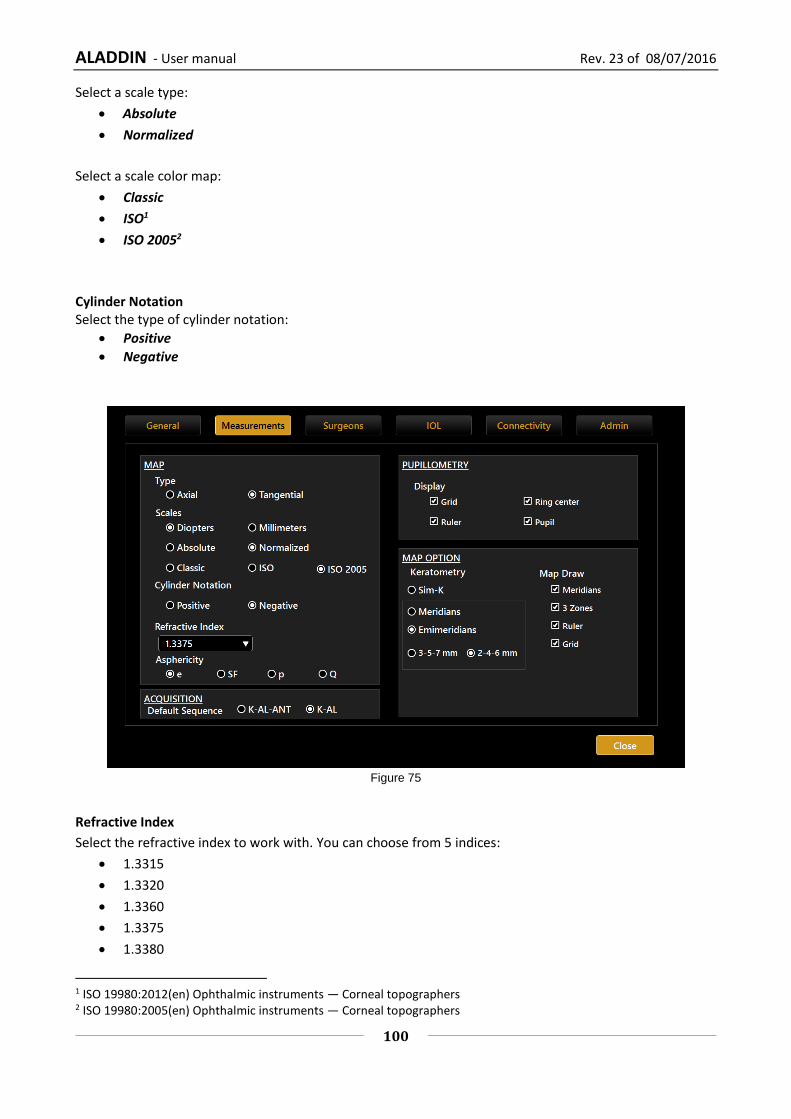
ALADDIN - User manual Rev. 23 of 08/07/2016
100
Select a scale type:
Absolute
Normalized
Select a scale color map:
Classic
ISO1
ISO 20052
Cylinder Notation Select the type of cylinder notation:
Positive
Negative
Figure 75
Refractive Index
Select the refractive index to work with. You can choose from 5 indices:
1.3315
1.3320
1.3360
1.3375
1.3380
1 ISO 19980:2012(en) Ophthalmic instruments — Corneal topographers 2 ISO 19980:2005(en) Ophthalmic instruments — Corneal topographers

ALADDIN - User manual Rev. 23 of 08/07/2016
101
Be careful because changing the index will result in a differently calculated Keratometry and Topographic
Map. Change this value at your discretion.
Asphericity
Select an asphericity unit of measure:
e
SF
p
Q Acquisition Select the default Biometry sequence acquisition:
K-AL-ANT: the default acquisition sequence is Keratometry->Axial Length->Anterior Segment (ACD)
K-AL: the default acquisition sequence is Keratometry->Axial Length. Anterior Segment (ACD) can be by pressing on the relative button

ALADDIN - User manual Rev. 23 of 08/07/2016
102
Topography Map Color scale
Previous software versions have always used the same color scale for Topography maps (absolute and
normalized), this is called “Classic” color scale. This software version introduces the possibility to switch the
scale to the ISO3 color scale and ISO20054 color scale, by going to Measures section of the settings. The color
scale option selected affects any topographic map drawing in the Aladdin application and in the printed
reports (also the custom ones).
The Classic and ISO absolute color scale are shown in the following figure for the same topography map.
Classic ISO
Absolute
scale
Classic
ISO
ISO
2005
Normalized
(adjustable)
scale
Classic
ISO
3 ISO 19980:2012(en) Ophthalmic instruments — Corneal topographers
4 ISO 19980:2005(en) Ophthalmic instruments — Corneal topographers
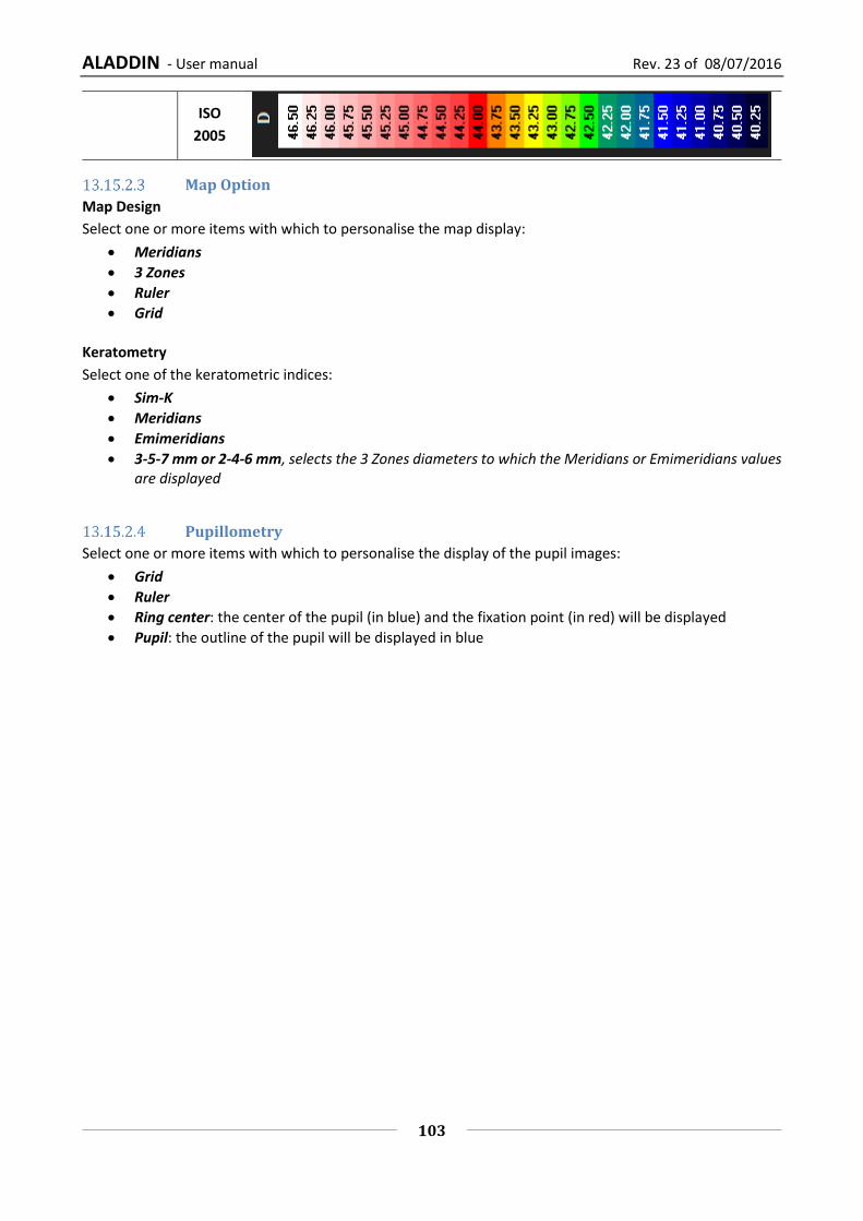
ALADDIN - User manual Rev. 23 of 08/07/2016
103
ISO
2005
Map Option
Map Design
Select one or more items with which to personalise the map display:
Meridians
3 Zones
Ruler
Grid
Keratometry
Select one of the keratometric indices:
Sim-K
Meridians
Emimeridians
3-5-7 mm or 2-4-6 mm, selects the 3 Zones diameters to which the Meridians or Emimeridians values are displayed
Pupillometry
Select one or more items with which to personalise the display of the pupil images:
Grid
Ruler
Ring center: the center of the pupil (in blue) and the fixation point (in red) will be displayed
Pupil: the outline of the pupil will be displayed in blue
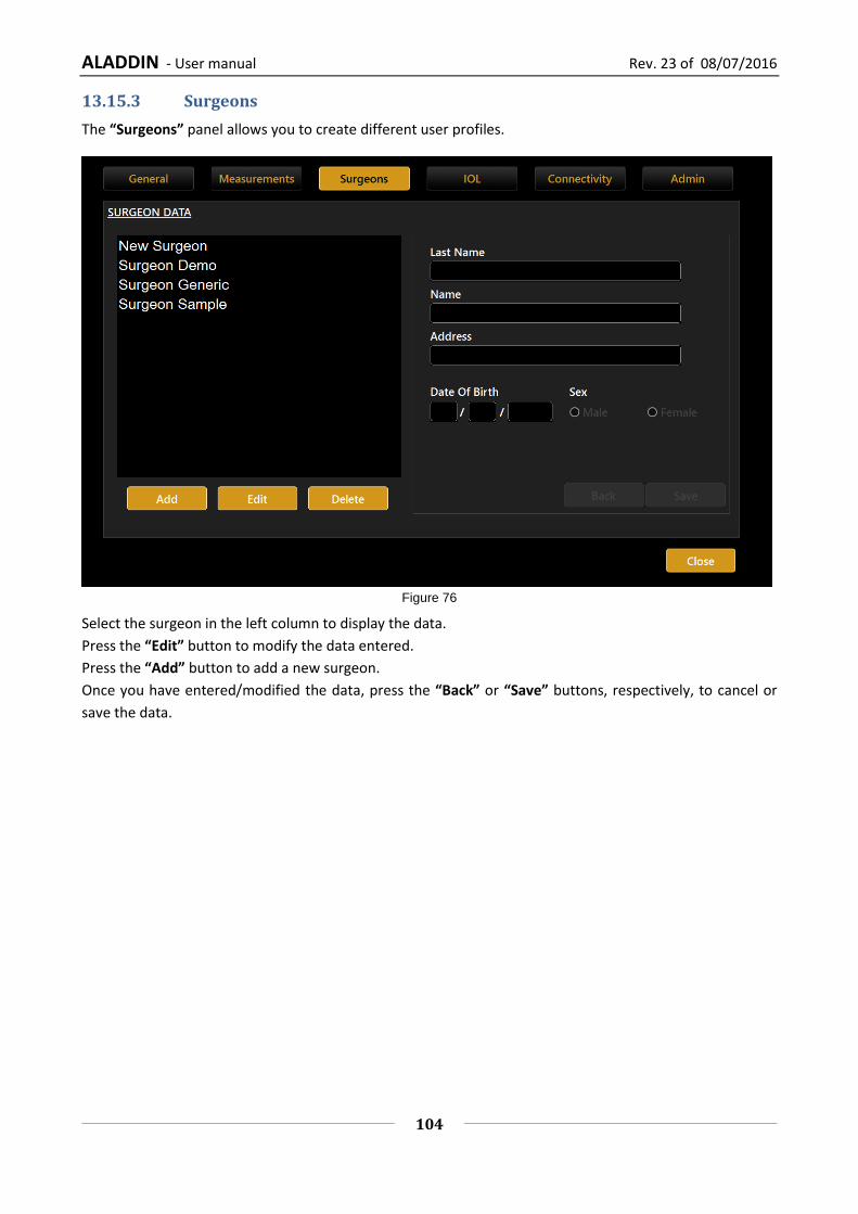
ALADDIN - User manual Rev. 23 of 08/07/2016
104
13.15.3 Surgeons
The “Surgeons” panel allows you to create different user profiles.
Figure 76
Select the surgeon in the left column to display the data.
Press the “Edit” button to modify the data entered.
Press the “Add” button to add a new surgeon.
Once you have entered/modified the data, press the “Back” or “Save” buttons, respectively, to cancel or
save the data.
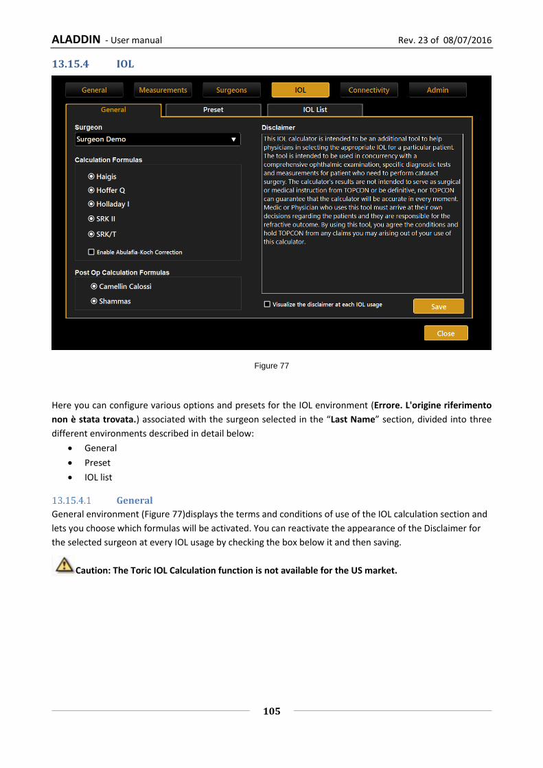
ALADDIN - User manual Rev. 23 of 08/07/2016
105
13.15.4 IOL
Figure 77
Here you can configure various options and presets for the IOL environment (Errore. L'origine riferimento
non è stata trovata.) associated with the surgeon selected in the “Last Name” section, divided into three
different environments described in detail below:
General
Preset
IOL list
General
General environment (Figure 77)displays the terms and conditions of use of the IOL calculation section and
lets you choose which formulas will be activated. You can reactivate the appearance of the Disclaimer for
the selected surgeon at every IOL usage by checking the box below it and then saving.
Caution: The Toric IOL Calculation function is not available for the US market.

ALADDIN - User manual Rev. 23 of 08/07/2016
106
Preset
Figure 78
The screen presented is as shown in Errore. L'origine riferimento non è stata trovata..
Each surgeon can set:
- Under “IOL” the preset for the IOL Calculation
- Under “Toric” the preset for the Toric IOL Calculation
- Under “Post Refractive” the preset for the Post Refractive IOL
By clicking on “Save” the selected settings are saved. This function will be particularly useful during the IOL
calculation, when the settings are reloaded each time as preset.
By pressing the “Reset” key, previous selections are reset, deleting all presets associated with the surgeon.
“IOL” and “Post Refractive IOL” sections have the same screen, the “Toric” one is presented in Figure 79.

ALADDIN - User manual Rev. 23 of 08/07/2016
107
Figure 79
Toric preset uses a different set of lenses (with only toric ones) and requires some additional settings with
respect to “IOL” and “Post Refractive IOL” sections.
In particular, you can specify the “Surgical Induced Astigmatism (SIA)” induced by the surgeon and the
“Incision Location” used during the surgery. You can decide to set the “Incision Location” at the Steep Axis
of the Keratometry or at a Fixed Value to be specified.
The “Toric Calculator Selection” is to choose between:
“Generic Toric Calculator”, that allows to define the lenses preset from a fully customizable collection
of models and manufacturers.
“Oculentis Calculator”, that allows to limit the collection of available lenses to Oculentis
manufacturer only. In this case the manufacturer selection is locked both in the preset set-up and in
the Toric IOL calculation environments.
This setting is per Surgeon.

ALADDIN - User manual Rev. 23 of 08/07/2016
108
Figure 80
IOL list
In this section (Figure 81) you can manage IOL spherical and torical lenses list. You can change the available
manufacturers and models by adding, deleting or editing them.
For each lens you can display and edit the constants used in each formula.
The two main environments, the “Spherical” and the “Torical” ones, can be selected clicking on the
corresponding button and have a similar layout.
13.15.4.3.1 IOL Spherical List
The “Spherical” layout is shown in Figure 81.
On the left side you can find the list of manufacturers, in the center their related spherical models while in
the right side the calculation constants of the selected lens.
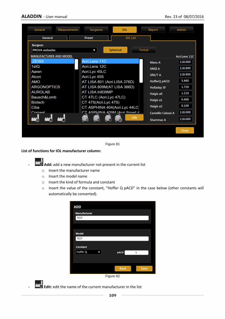
ALADDIN - User manual Rev. 23 of 08/07/2016
109
Figure 81
List of functions for IOL manufacturer column:
- Add: add a new manufacturer not present in the current list
o Insert the manufacturer name
o Insert the model name
o Insert the kind of formula and constant
o Insert the value of the constant, “Hoffer Q pACD” in the case below (other constants will
automatically be converted).
Figure 82
- Edit: edit the name of the current manufacturer in the list

ALADDIN - User manual Rev. 23 of 08/07/2016
110
- Delete: delete a manufacturer. Please note that this function will also delete every IOL
associated to the current manufacturer.
List of functions for IOL model column:
- Add: add a new IOL model to the current manufacturer:
o Insert the model name
o Insert the kind of formula and constant
o Insert the value of the constant, “Haigis A0” in the case below (other constants will
automatically be converted).
Figure 83
- Edit: edit the name of the current IOL
- Delete: delete the selected IOL
- Calculation Constants History: gives information on every change of calculation constants
values as shown in Figure 84.
The possible sources of edit are “Manual” (constants values changed manually by the user), “ULIB”
(constants values changed after an ULIB update) and “Restore” (constants values restored by the
user to a previous version). To restore a previous version you need to select the version to be restored
and then click on the yellow right-arrow and then click on save button.
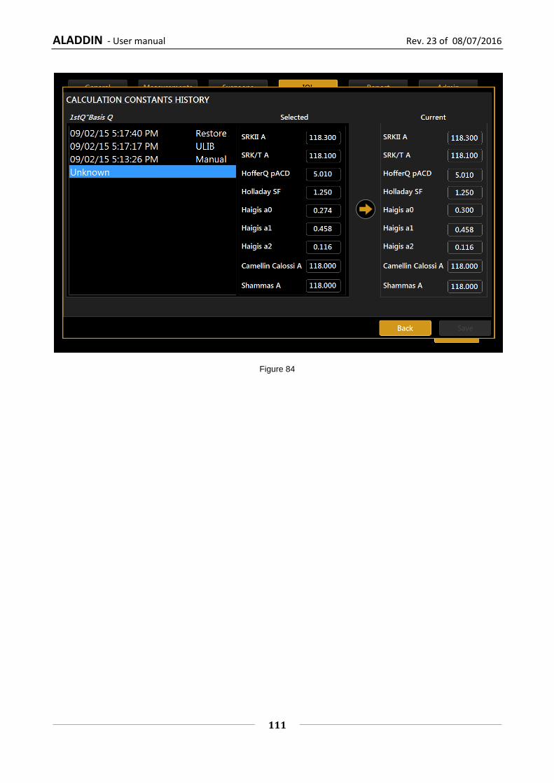
ALADDIN - User manual Rev. 23 of 08/07/2016
111
Figure 84
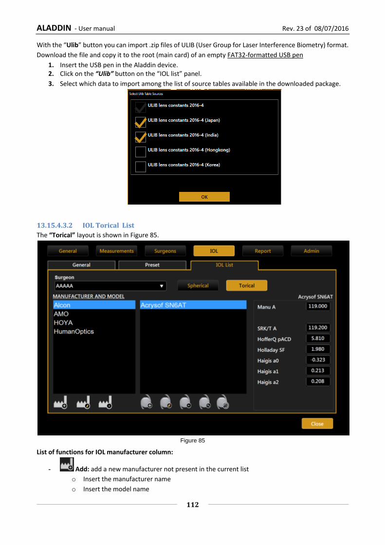
ALADDIN - User manual Rev. 23 of 08/07/2016
112
With the “Ulib” button you can import .zip files of ULIB (User Group for Laser Interference Biometry) format.
Download the file and copy it to the root (main card) of an empty FAT32-formatted USB pen
1. Insert the USB pen in the Aladdin device. 2. Click on the “Ulib” button on the “IOL list” panel.
3. Select which data to import among the list of source tables available in the downloaded package.
13.15.4.3.2 IOL Torical List
The “Torical” layout is shown in Figure 85.
Figure 85
List of functions for IOL manufacturer column:
- Add: add a new manufacturer not present in the current list
o Insert the manufacturer name
o Insert the model name

ALADDIN - User manual Rev. 23 of 08/07/2016
113
o Insert the kind of formula and constant
o Insert the value of the constant, “Hoffer Q pACD” in the case below (other constants will
automatically be converted)
o Define the “Sphere Power Range”, inserting the minimum, the maximum and the step of the
spherical power of the lens
o Choose the “Cylinder Definition” of the lens, with “Sub models” or “Cylinder Range Based”.
If you select “Sub models” (Figure 86) you can add a list of sub models each of them
with a different cylinder value of Toricity, using the IOL button under the table (add,
edit and delete).
If you select “Cylinder Range Based” (Figure 87), you have to insert the minimum,
the maximum and the step of the cylinder value in order to define the toricity range
of the lens.
Figure 86
Figure 87
ALADDIN - User manual Rev. 23 of 08/07/2016
114
- Edit: edit the name of the current manufacturer in the list
- Delete: delete a manufacturer. Please note that this function will also delete every IOL
associated to the current manufacturer.
List of functions for IOL model column:
- Add: add a new IOL model to the current manufacturer, with the same procedure described in
the “Add Toric Manufacturer” section above.
- Edit: edit the name and the properties of the current IOL
- Delete: delete the selected IOL
- View Properties: visualize properties, calculation constants and list of sub models of the lens
(or cylinder range)
- Calculation Constants History: gives information on every change of calculation constants
values. The layout is similar to the one in Figure 84.
The possible sources of edit are “Manual” (constants values changed manually by the user) and
“Restore” (constants values restored by the user to a previous version). To restore a previous version
you need to select the version to be restored and then click on the yellow right-arrow and then click
on save button.

ALADDIN - User manual Rev. 23 of 08/07/2016
115
13.15.5 Connectivity
This panel (Figure 88) allows you to configure all the settings relative to network connectivity with external
softwares or storage destinations.
Figure 88
Network folder configuration
The “NETWORK FOLDER” panel allows the user to configure and use a remote network folder to store Aladdin
reports.
That resource will then become selectable as a destination in the report’s print form.
In order for Aladdin to be able to connect to the remote network folder, you must configure Aladdin setting
the correct access credentials for the remote resource.
Configuration parameters:
Network folder path: the path to access the network folder location (without trailing backslashes)
eg.
\\10.0.0.81\path_to\AladdinSandbox
\\TopconNetwork\path_to\AladdinSandbox
Username: specify the domain name if needed
eg.
TopconDomain\username
Password: for the specified username
When you click on the “Configure” button the system starts searching for the network resource. This
procedure may take some time depending on the network. Failure or success to connect to the network

ALADDIN - User manual Rev. 23 of 08/07/2016
116
resource is reported as shown in Figure 89. Connection failure may be due to unreachable resource path or
to wrong credentials.
Figure 89
XML Export
Enables/Disables XML option for exporting XML data of the exam to the network folder by the export
window.
IMAGEnet i-base software
Aladdin can receive and transfer data to Topcon IMAGEnet i-base through a wireless or LAN network.
IMAGEnet i-base is activated by clicking on the Enabled Option and by providing the IP address of the machine
we want to connect to. By clicking on the Configure button (Figure 88) the user is presented with a list of IP
Addresses of the machines running IMAGEnet i-base software that are reachable from Aladdin. Once selected
the proper IP( Figure 90), Aladdin is ready to exchange data with IMAGEnet i-base machine.

ALADDIN - User manual Rev. 23 of 08/07/2016
117
Figure 90
IMAGEnet 6 Server software
Aladdin can receive and transfer data to Topcon IMAGEnet 6 Server through a wireless or LAN network.
IMAGEnet 6 Server is activated by clicking on the Enabled Option and by providing the IP address of the
external server we want to connect to. Once we have selected the proper IP, Aladdin is ready to exchange
data with the IMAGEnet 6 Server machine (Figure 91).
Figure 91
Export to External Software settings
In this panel it is possible to control two main aspects of the device behaviour in relation to the exportation
function.
“Perform Exportation when Saving”, allows to be prompted automatically the exportation form once
saving a new or existing exam.
“Don’t ask for Confirmation when Exporting”, allows to skip the selection of targets when performing
the exportation while saving or when pressing on the export button

ALADDIN - User manual Rev. 23 of 08/07/2016
118
It is also possible to access configuration (“Configure” button) of the other external software destinations
which are not present in the other panels of this section.
By activating the checkbox of an export destination, this is included in the targets of the exportation function.
PhacoOptics®: http://www.phacooptics.net/
In order to get exam data to exported to PhacoOptics® software, running on an external PC, it is necessary
to configure a network path and access credentials for the target of exportation. Refer to PhacoOptics®
manuals on how to get the data exported from Aladdin inside the application.

ALADDIN - User manual Rev. 23 of 08/07/2016
119
DICOM
The DICOM panel of Connectivity section allows to set the needed parameters for the connections to the
available DICOM services.
The available services are:
Modality Worklist, The DICOM Modality Worklist service provides a list of imaging procedures that
have been scheduled for performance by the acquisition device.
Patient Root Query, This enables the device to find patient’s details from a DICOM server.
Storage, The DICOM Store service is used to send images or other persistent objects (structured
reports, etc.) to picture archiving and communication system (PACS) or workstation.
Storage Commitment The DICOM Storage Commitment service is used to confirm that an image
has been permanently stored by a device.
For each services the needed parameter are:
Remote Application Entity (AE) title
Remote IP address
Remote connection port
The “Local Application Entity title” is the identifier name through which the device presents itself to the
servers.
The “N-EVENT Report node port” is the port at which the device is able to receive N-EVENT REPORTS for
storage commitments (default is 115).

ALADDIN - User manual Rev. 23 of 08/07/2016
120
The connectivity to the defined server can be tested using the “C-ECHO” function activated by the relative
“Connection Test” button. The result of connection test is shown by the green or red icon.
In order to configure properly the full DICOM workflow it could be necessary to perform some operations or
configurations on the server’s side. In order to do this contact the System Administrator.
The DICOM module of Aladdin is describe in detail in its DICOM Conformance Statement. Visit
http://www.topconmedical.com/conformance.cfm to download it.

ALADDIN - User manual Rev. 23 of 08/07/2016
121
13.15.6 Admin
Figure 92
This is the instrument's administration panel (Figure 92).
It provides certain information on the system: serial number (S/N) and software version (S/V). The “Check” button starts the calibration check procedure.
Check the calibration
See the paragraph describing the procedure Checking the calibration.
It is absolutely essential to check the calibration when the device has been transported from
one place to another and when it has suffered an impact or thermal shocks.
It is recommended to check the measurements every day when turning on the device.
The “Application” frame manages the behavior of the integrated software:
Upgrade Updates the integrated software
Backup Starts the backup procedure on a USB driver
Close App Closes the application
Report
In the “Report” panel of Admin section it is possible to set a Custom header for all the reports, as well as
setting the output format of reports exported to network folder. The available formats are: Pdf, Jpeg, Bmp,
Tiff, Png.
It is also possible to set the automatic saving of the exam after printing.

ALADDIN - User manual Rev. 23 of 08/07/2016
122
Remote Assistance
In case you need remote Assistance the Aladdin application integrates Teamviewer QS (Quick Support) pre-
installed.
There is NO NEED to disable the Write Filter protection
Ensure to have available internet access for your Aladdin unit
Go to Settings -> Admin and press “Remote Assistance”.
Wait for the Teamviewer Window to open
Communicate to the Remote Operator the ID shown under “Your ID” and wait for the incoming
connection
The password is masked, the operator knows it already
To turn off manually the Remote Assistance you can close the Teamviewer window or press “Remote Ass.
OFF”
If you get one of the following windows please check your internet connection to Aladdin or contact your IT
staff.

ALADDIN - User manual Rev. 23 of 08/07/2016
123
Updating the integrated software
In this section is described the software upgrade procedure from one version to the following version.
To update the software, perform the following operations:
1. Unpack the update packet in the root (main card) of an empty FAT32-formatted USB external drive. 2. Switch on the Aladdin. 3. Cancel the calibration check (Figure 93).
Figure 93
4. Click on the settings icon (Figure 94).

ALADDIN - User manual Rev. 23 of 08/07/2016
124
Figure 94
5. Click on the “Admin” tab (Figure 95).
Figure 95
6. Insert the USB stick with the “Aladdin upgrade” files in one of the USB ports (Figure 96).
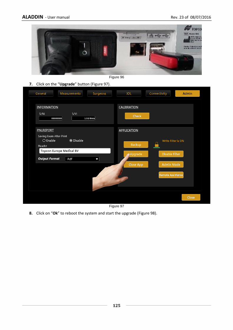
ALADDIN - User manual Rev. 23 of 08/07/2016
125
Figure 96
7. Click on the “Upgrade” button (Figure 97).
Figure 97
8. Click on “Ok” to reboot the system and start the upgrade (Figure 98).

ALADDIN - User manual Rev. 23 of 08/07/2016
126
Figure 98
9. After the upgrade you will see the message of Figure 99 on the screen.
Figure 99
10. The system will reboot and starts the “Aladdin application”.
11. After restart, the software updates the system; this operations could take some minutes please
don’t restart machine during this procedure (Figure 100).

ALADDIN - User manual Rev. 23 of 08/07/2016
127
Figure 100
12. If you see the message of Figure 101, please switch off your Aladdin and turn it on again. Your
Aladdin should now works fine.
Figure 101
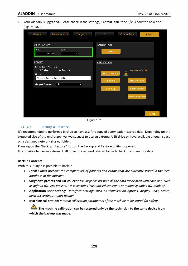
ALADDIN - User manual Rev. 23 of 08/07/2016
128
13. Your Aladdin is upgraded. Please check in the settings, “Admin” tab if the S/V is now the new one
(Figure 102).
Figure 102
Backup & Restore
It’s recommended to perform a backup to have a safety copy of every patient stored data. Depending on the
expected size of the entire archive, we suggest to use an external USB drive or have available enough space
on a designed network shared folder.
Pressing on the “Backup _Restore” button the Backup and Restore utility is opened.
It is possible to use an external USB drive or a network shared folder to backup and restore data.
Backup Contents
With this utility it is possible to backup:
Local Exams archive: the complete list of patients and exams that are currently stored in the local
database of the machine
Surgeon’s presets and IOL collections: Surgeons list with all the data associated with each one, such
as default IOL lens presets, IOL collections (customized constants or manually added IOL models)
Application user settings: interface settings such as visualization options, display units, scales,
network settings, report header
Machine calibration: internal calibration parameters of the machine to be stored for safety.
The machine calibration can be restored only by the technician to the same device from
which the backup was made.

ALADDIN - User manual Rev. 23 of 08/07/2016
129
Backup Procedure
To perform the backup connect the desired USB external storage device or switch to Network Folder option.
1. Select the desired destination:
USB, select the desired partition from the list of the available
Network folder, define (if not already defined) the desired network shared folder destination,
check the connectivity.

ALADDIN - User manual Rev. 23 of 08/07/2016
130
2. Press “Backup” button, wait for the procedure to complete. Press “OK” to confirm the operation or
“No” to do not perform the backup.
Do not turn off the device or unplug the power supply and ethernet cable while performing
this operation. Do not unplug USB devices if USB is the backup destination. This may take several
minutes depending on the exam archive size.
3. After the procedure is completed, a new entry appears in the list of available backup data with the
following naming convention:
AladdinBackup_Standalone_<device serial number>_<backup date>
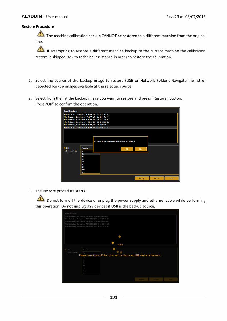
ALADDIN - User manual Rev. 23 of 08/07/2016
131
Restore Procedure
The machine calibration backup CANNOT be restored to a different machine from the original
one.
If attempting to restore a different machine backup to the current machine the calibration
restore is skipped. Ask to technical assistance in order to restore the calibration.
1. Select the source of the backup image to restore (USB or Network Folder). Navigate the list of
detected backup images available at the selected source.
2. Select from the list the backup image you want to restore and press “Restore” button.
Press “OK” to confirm the operation.
3. The Restore procedure starts.
Do not turn off the device or unplug the power supply and ethernet cable while performing
this operation. Do not unplug USB devices if USB is the backup source.
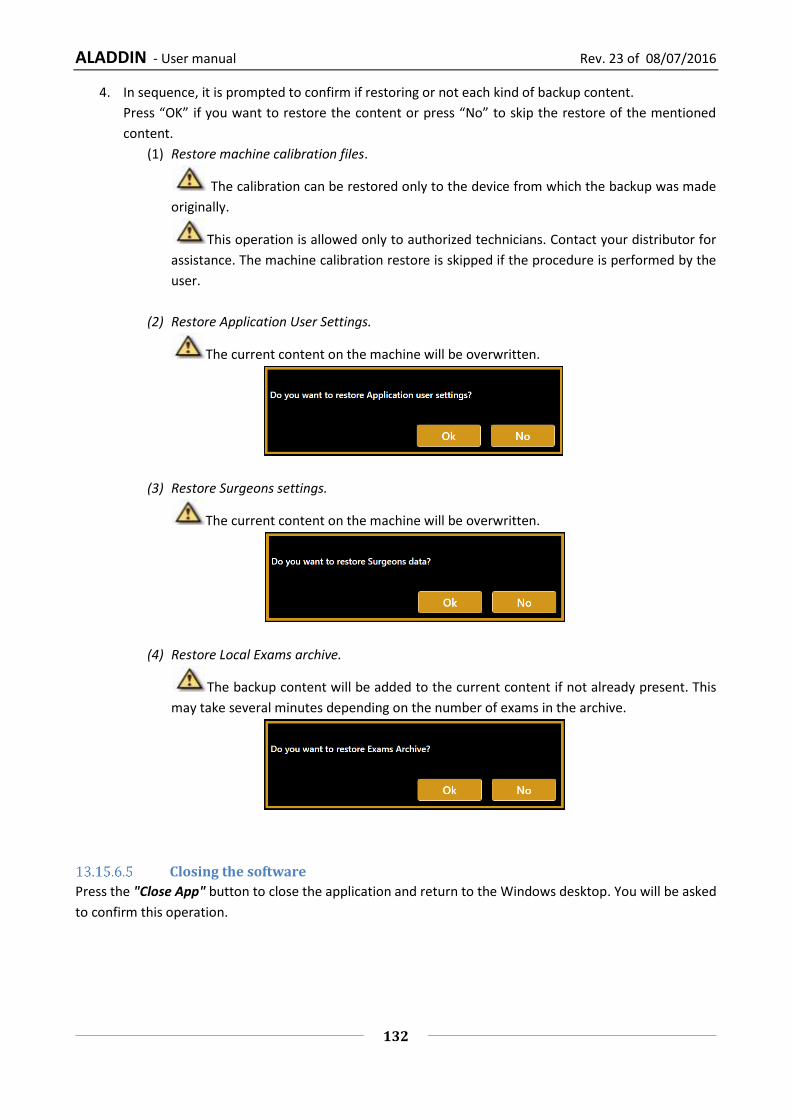
ALADDIN - User manual Rev. 23 of 08/07/2016
132
4. In sequence, it is prompted to confirm if restoring or not each kind of backup content.
Press “OK” if you want to restore the content or press “No” to skip the restore of the mentioned
content.
(1) Restore machine calibration files.
The calibration can be restored only to the device from which the backup was made
originally.
This operation is allowed only to authorized technicians. Contact your distributor for
assistance. The machine calibration restore is skipped if the procedure is performed by the
user.
(2) Restore Application User Settings.
The current content on the machine will be overwritten.
(3) Restore Surgeons settings.
The current content on the machine will be overwritten.
(4) Restore Local Exams archive.
The backup content will be added to the current content if not already present. This
may take several minutes depending on the number of exams in the archive.
Closing the software
Press the "Close App" button to close the application and return to the Windows desktop. You will be asked
to confirm this operation.

ALADDIN - User manual Rev. 23 of 08/07/2016
133
14 Operating voltage and fuse change
14.1 Changing the operating voltage
Step 1
Open the fuse box cover
using a screwdriver
Step 2
Take out the red fuse box
(use a screwdriver to release
it)
Step 3
Make sure the fuses stay in
the correct position
Step 4
Rotate the fusebox 180° so
the 115V text is on the left
side and put it back in the
black fuse box
Step 5
Push the red fuse box
carefully back into position
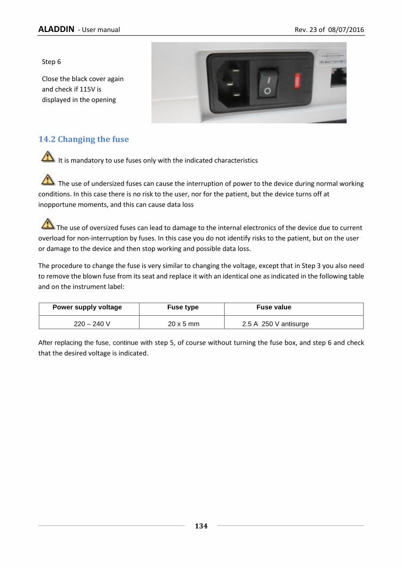
ALADDIN - User manual Rev. 23 of 08/07/2016
134
Step 6
Close the black cover again
and check if 115V is
displayed in the opening
14.2 Changing the fuse
It is mandatory to use fuses only with the indicated characteristics
The use of undersized fuses can cause the interruption of power to the device during normal working
conditions. In this case there is no risk to the user, nor for the patient, but the device turns off at
inopportune moments, and this can cause data loss
The use of oversized fuses can lead to damage to the internal electronics of the device due to current
overload for non-interruption by fuses. In this case you do not identify risks to the patient, but on the user
or damage to the device and then stop working and possible data loss.
The procedure to change the fuse is very similar to changing the voltage, except that in Step 3 you also need
to remove the blown fuse from its seat and replace it with an identical one as indicated in the following table
and on the instrument label:
Power supply voltage Fuse type Fuse value
220 – 240 V 20 x 5 mm 2.5 A 250 V antisurge
After replacing the fuse, continue with step 5, of course without turning the fuse box, and step 6 and check
that the desired voltage is indicated.
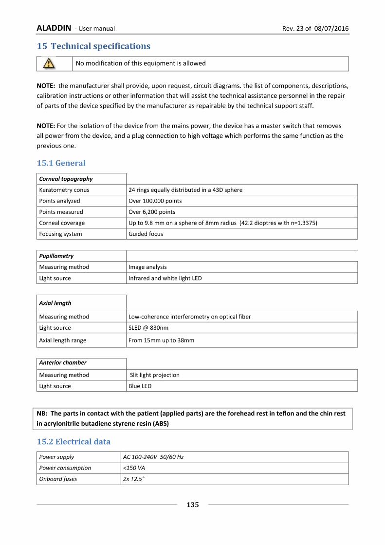
ALADDIN - User manual Rev. 23 of 08/07/2016
135
15 Technical specifications
No modification of this equipment is allowed
NOTE: the manufacturer shall provide, upon request, circuit diagrams. the list of components, descriptions,
calibration instructions or other information that will assist the technical assistance personnel in the repair
of parts of the device specified by the manufacturer as repairable by the technical support staff.
NOTE: For the isolation of the device from the mains power, the device has a master switch that removes
all power from the device, and a plug connection to high voltage which performs the same function as the
previous one.
15.1 General
Corneal topography
Keratometry conus 24 rings equally distributed in a 43D sphere
Points analyzed Over 100,000 points
Points measured Over 6,200 points
Corneal coverage Up to 9.8 mm on a sphere of 8mm radius (42.2 dioptres with n=1.3375)
Focusing system Guided focus
Pupillometry
Measuring method Image analysis
Light source Infrared and white light LED
Axial length
Measuring method Low-coherence interferometry on optical fiber
Light source SLED @ 830nm
Axial length range From 15mm up to 38mm
Anterior chamber measurement
Measuring method Slit light projection
Light source Blue LED
NB: The parts in contact with the patient (applied parts) are the forehead rest in teflon and the chin rest
in acrylonitrile butadiene styrene resin (ABS)
15.2 Electrical data
Power supply AC 100-240V 50/60 Hz
Power consumption <150 VA
Onboard fuses 2x T2.5°

ALADDIN - User manual Rev. 23 of 08/07/2016
136
Device Class for EN 60601-1 Class I
15.3 Optical radiation
1) Axial length measurement
Source: Sled
Wavelength 830 nm
Power on patient's eye: < 0.6 mW
Source: IR LED (crown)
Wavelength: 770 nm
Power on patient's eye: < 0.1 mW
2) Central fixation LED
Yellow green
Source: LED
Wavelength: 572 nm
Power on patient's eye: <0.01 mW
3) Illumination of Placido disk for topographic analysis
Source: Red LED Type1
Wavelength: 633 nm
Power on patient's eye: <0.02 mW
Source: Red LED Type2
Wavelength: 615 -630 nm
Power on patient's eye: <0.02 mW
4) Pupilometric analysis
Source: White LED
Blue Green Red
Wavelength: 473 532 630 nm
Power on patient's eye: 0.03 0.005 0.008 cd
Source: IR LED
Wavelength: 780 nm
Power on patient's eye: <0.4 mW
5) ACD measurement
Source: Blue LED
Wavelength: 473 nm
Power on patient's eye: <0.07 mW
Caution should be practised when using the device’s ACD measurement for any given intraocular lens
calculation because of the high variability of this measurement.
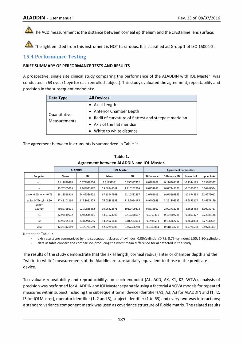
ALADDIN - User manual Rev. 23 of 08/07/2016
137
The ACD measurement is the distance between corneal epithelium and the crystalline lens surface.
The light emitted from this instrument is NOT hazardous. It is classified ad Group 1 of ISO 15004-2.
15.4 Performance Testing
BRIEF SUMMARY OF PERFORMANCE TESTS AND RESULTS
A prospective, single site clinical study comparing the performance of the ALADDIN with IOL Master was
conducted in 63 eyes (1 eye for each enrolled subject). This study evaluated the agreement, repeatability and
precision in the subsequent endpoints:
Data Type All Devices
Quantitative
Measurements
Axial Length
Anterior Chamber Depth
Radii of curvature of flattest and steepest meridian
Axis of the flat meridian
White to white distance
The agreement between instruments is summarized in Table 1:
Table 1.
Agreement between ALADDIN and IOL Master.
ALADDIN IOL Master Agreement parameters
Endpoint Mean SD Mean SD Difference Difference SD lower LoA upper LoA
acd 3.417830688 0.679989056 3.31952381 0.650987552 0.0983069 0.116363197 -0.1344195 0.33103327
al 23.70365079 1.703971867 23.68846561 1.710252709 0.0151852 0.027245176 -0.0393052 0.06967554
ax for 0.00<=cyl<=0.75 88.18518519 94.49566422 87.53947368 92.10832857 2.0765015 9.975699862 -17.874898 22.0279012
ax for 0.75<cyl<=1.50 77.48101266 115.8921525 76.05882353 114.2054185 0.9400949 3.261808332 -5.5835217 7.46371159
ax for
1.50<cyl 40.82758621 92.30826382 39.96428571 103.2499472 0.8218912 2.093718248 -3.3655453 5.00932767
k1 42.93549692 2.400645881 43.01523003 2.415238617 -0.0797331 0.154802285 -0.3893377 0.22987146
k2 43.90205198 2.589996595 43.99521136 2.600533074 -0.0931594 0.186267212 -0.4656938 0.27937504
wtw 12.28312169 0.525703699 12.32291005 0.557496798 -0.0397884 0.118840715 -0.2774698 0.19789307
Note to the Table 1:
- axis results are summarized by the subsequent classes of cylinder: 0.00cylinder0.75; 0.75<cylinder1.50; 1.50<cylinder. - data in table concern the comparison producing the worst mean difference for al detected in the study.
The results of the study demonstrate that the axial length, corneal radius, anterior chamber depth and the
“white-to-white” measurements of the Aladdin are substantially equivalent to those of the predicate
device.
To evaluate repeatability and reproducibility, for each endpoint (AL, ACD, AX, K1, K2, WTW), analysis of
precision was performed for ALADDIN and IOLMaster separately using a factorial ANOVA models for repeated
measures within subject including the subsequent term: device identifier (A1, A2, A3 for ALADDIN and I1, I2,
I3 for IOLMaster), operator identifier (1, 2 and 3), subject identifier (1 to 63) and every two-way interactions;
a standard variance component matrix was used as covariance structure of R-side matrix. The related results

ALADDIN - User manual Rev. 23 of 08/07/2016
138
were used to estimate: - the reproducibility SD as the square root of model MSE; the reproducibility limit as
reproducibility SD multiplied by 2.88; the reproducibility coefficient of variation as (reproducibility SD / mean)
multiplied 100; - the repeatability SD as the square root of (device variance component estimate + operator
variance component estimate + device*subject variance component estimate + operator*subject variance
component estimate + model MSE); the repeatability limit as repeatability SD multiplied by 2.88; the
repeatability coefficient of variation as (repeatability SD / mean) multiplied 100.
Variability of repeated measures within a subject was assessed before ANOVA modeling to guarantee that it is fairly constant across the range of results, as proved:
- plotting the standard deviation of repeated results with eye versus the mean of repeated results (data not shown);
- estimating the Spearman correlation coefficient between the standard deviation of repeated results with eye versus the mean of repeated results (data not shown).
The results of the analysis of repeatability and reproducibility are summarized in Table 2:
TABLE2 Repeatability and reproducibility.
DEVICE Endpoint Overall Mean REPEATABILITY REPRODUCIBILITY
SD Limit % COV SD Limit % COV
ALADDIN acd 3.397248677 0.027579116 0.079427855 0.811807407 0.519528412 1.496241828 15.29262241
ALADDIN al 23.69804821 0.018530025 0.053366472 0.078192199 0.129821027 0.373884559 0.547813162
ALADDIN ax for
0.00<=cyl<=0.75 86.90250329 5.519759822 15.89690829 6.351669529 13.3944358 38.57597511 15.41317602
ALADDIN ax for
0.75<cyl<=1.50 75.94121105 2.224842528 6.407546481 2.929690608 5.955000696 17.150402 7.841593008
ALADDIN ax for 1.50<cyl 75.94121105 1.728735737 4.978758923 2.276413179 4.843085162 13.94808527 6.377413653
ALADDIN k1 42.9413081 0.086388248 0.248798153 0.201177494 0.418268114 1.204612167 0.974046046
ALADDIN k2 43.90794572 0.110161562 0.3172653 0.250892089 0.507055765 1.460320604 1.154815505
ALADDIN wtw 12.27800118 0.065896179 0.189780996 0.536701196 0.264318617 0.761237618 2.152782146
IOLMaster acd 3.327983539 0.048812637 0.140580394 1.46673312 0.241207692 0.694678153 7.247863133
IOLMaster al 23.69269841 0.018705725 0.053872489 0.078951435 0.082094224 0.236431364 0.346495879
IOLMaster ax for
0.00<=cyl<=0.75 88.66187221 7.444327655 21.43966365 8.39631227 15.80848015 45.52842284 17.83007708
IOLMaster ax for
0.75<cyl<=1.50 75.96493239 2.164421305 6.233533358 2.849237453 16.539422 47.63353535 21.77244351
IOLMaster ax for 1.50<cyl 75.96493239 1.867818382 5.379316939 2.45879029 5.710886052 16.44735183 7.517792582
IOLMaster k1 43.0005842 0.082012189 0.236195103 0.190723429 0.330063483 0.950582831 0.767579067
IOLMaster k2 43.99408476 0.093346514 0.268837961 0.212179694 0.53105056 1.529425614 1.20709537
IOLMaster wtw 12.30152851 0.092008195 0.264983602 0.747941161 0.445406739 1.282771408 3.620743053
Note to Table 2:
- Repeatability includes variation due to measurement error; - Reproducibility includes variations due to device, operator, interaction between device and subject, interaction between
operator and subject, and measurement error; - Repeatability % COV = (Repeatability SD / abs(overall mean))*100; - Reproducibility % COV = (Reproducibility SD / abs(overall mean))*100.
The result of the repeatability and reproducibility study demonstrate that ALADDIN is substantially equivalent for both repeatability and reproducibility to the predicate device.
Agreement study and reproducibility and repeatability study prove that ALADDIN performances are substantially equivalent to the predicate device ones for the assessed endpoints.

ALADDIN - User manual Rev. 23 of 08/07/2016
139
15.5 Information on measurements
1) Anterior chamber depth
Measuring range 1.5 – 5.5 mm
Display resolution 0.01 mm
Repeatability in live mode ±0.1 mm
2) Axial length
Measuring range 15 - 38 mm
Display resolution 0.01 mm
Repeatability in live mode ±0.016 mm
3) Corneal Topography/Keratometry (radius and axes of the main meridians)
Curve Radius (mm)
Measuring range 3.3 -37.5 mm
Display resolution 0.01 mm
Repeatability in live mode ±0.02 mm
Diopter Curve Radius (D) (n=1.3375)
Measuring range 9.0 -101.5 D
Display resolution 0.01 D
Repeatability in live mode ±0.12 D
4) Limbus (WTW)
Measuring range 6 – 18 mm
Display resolution 0.01 mm
Repeatability in live mode ±0.05 mm
5) Pupil dimension
Measuring range 0.5 – 10 mm
Display resolution 0.01 mm
Repeatability in live mode ±0.05 mm
15.6 Environmental conditions
For operation: Storage: Transport:
Temperature 10-40° C 0-40° C 0-40° C
Relative humidity 8-75% (non condensing) 8-75% (non condensing) 8-75% (non condensing)
Atmospheric pressure 700-1060 hPa 700-1060 hPa 500-1060 hPa

ALADDIN - User manual Rev. 23 of 08/07/2016
140
15.7 Mechanical Specifications
Device:
Packaged
product:
Width 320mm 600mm
Height 490mm 800mm
Length 470mm 710mm
Weight 18 kg 29kg
15.8 Other Specifications: Onboard PC component specifications
Hardware 1.0 Hardware 2.0
Operating system WINDOWS XP Embedded WINDOWS 7 Embedded
Processor Intel Atom N270 AMD G-T56N
RAM 1GB 2GB
Hard disk 160GB 250GB
External connections LAN integrated, 2 xUSB LAN integrated, 2 xUSB

ALADDIN - User manual Rev. 23 of 08/07/2016
141
16 Declaration of conformity
DECLARATION OF CONFORMITY/ Dichiarazione di conformità:
Manufacturer/Fabbricante :
Name/Nome : VISIA imaging S.r.l.
Address/Indirizzo : Via C.E. Gadda, 15 – 52027 San Giovanni Valdarno (AR) – ITALY
Name of device/Nome del dispositivo :
BIOMETER and CORNEAL ANALYSER integrated
Marca/Brand : TOPCON
Model/Modello : ALADDIN
I, the undersigned, hereby declare that the aforementioned devices comply with Directive 93/42/EEC (implemented in Italy by Legislative Decree no. 46/97) and subsequent amendments and additions (Directive 2007/47/EC – implemented in Italy by Legislative Decree no. 037/10) for Class IIa equipment.
Io, sottoscritto, con la presente dichiaro che i dispositivi specificati sopra sono conformi alla Direttiva 93/42/CEE (recepita in Italia con D.Lgs 46/97) e successive modifiche e integrazioni (Direttiva 2007/47/CE – recepita in Italia con D.Lgs 037/10) per i dispositivi di Classe IIa.
Alessandro Foggi
Managing director
Legal representative

ALADDIN - User manual Rev. 23 of 08/07/2016
142
17 Appendix: Installing an external printer
17.1 Getting drivers and transferring them to ALADDIN
It is recommended to download the latest drivers for the printer and this should be done through an external
PC. Download the latest drivers in the Technical Support section of the printer manufacturer site.
Download the drivers, which usually come in a zipped folder. Unzip it and keep the .inf file somewhere easily
accessible (for example “C:\Drivers”). Copy them to the root directory of an USB FAT32 formatted pen driver
that will later be connected to the ALADDIN USB port.
Now go back to ALADDIN and disable the “Write Filter” carrying out the following steps:
17.2 Disabling the Write Filter
1. Disable the Write Filter in the Admin
tab of Settings panel and Confirm.
SettingsAdmin Disable Filter
Press OK
2. The machine will restart
automatically.
3. Upon restarting, the Aladdin
application will warn about the
unsafe state of the system.
Press Cancel to avoid the restarting of
the machine.
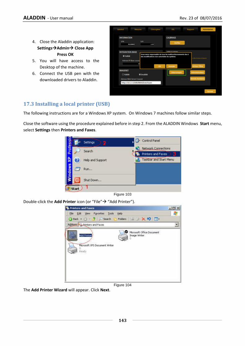
ALADDIN - User manual Rev. 23 of 08/07/2016
143
4. Close the Aladdin application:
SettingsAdmin Close App
Press OK
5. You will have access to the
Desktop of the machine.
6. Connect the USB pen with the
downloaded drivers to Aladdin.
17.3 Installing a local printer (USB)
The following instructions are for a Windows XP system. On Windows 7 machines follow similar steps.
Close the software using the procedure explained before in step 2. From the ALADDIN Windows Start menu,
select Settings then Printers and Faxes.
Figure 103
Double-click the Add Printer icon (or “File” “Add Printer”).
Figure 104
The Add Printer Wizard will appear. Click Next.

ALADDIN - User manual Rev. 23 of 08/07/2016
144
Figure 105
Select “Local printer attached to this computer” and make sure that the Automatically detect and install my Plug and Play printer checkbox is not checked. Click Next.
Figure 106
You now need to identify the make and model of the printer. Click on the Have Disk... button.
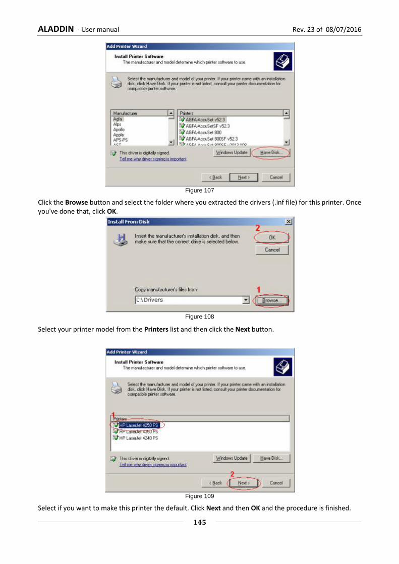
ALADDIN - User manual Rev. 23 of 08/07/2016
145
Figure 107
Click the Browse button and select the folder where you extracted the drivers (.inf file) for this printer. Once you've done that, click OK.
Figure 108
Select your printer model from the Printers list and then click the Next button.
Figure 109
Select if you want to make this printer the default. Click Next and then OK and the procedure is finished.

ALADDIN - User manual Rev. 23 of 08/07/2016
146
It is now very important to re-enable the Write Filter. Follow the instructions under “Re-Enabling the Write Filter”, otherwise there is the risk of damaging the device.
17.4 Installing a network printer (LAN)
Connect ALADDIN to an external network through the LAN port using an Ethernet cable.
Figure 110
This time, select “A network printer, or a printer attached to another computer”
Now select “Create a new port”, then select "Standard TCP/IP Port" from the Type of port drop-down menu. Click Next.
Figure 111
Enter the Printer Name or IP address in the “Printer Name” textbox. Port Name will automatically be entered. You can leave the default. Click Next. There will be a small delay while your computer configures the port.

ALADDIN - User manual Rev. 23 of 08/07/2016
147
Figure 112
From here on, follow the same procedure as described for “Installing a local printer (USB)”
17.5 Re-Enabling the Write Filter
1. Open the Aladdin application.
2. The system will warn about the unsafe
state.
3. Wait for the automatic restart or press OK.
4. The system will restart enabling the write
filter.
5. Once restarted, the system will be in a safe
state.
OR
1. From inside the application if already open
go to:
SettingsAdmin Enable Filter
2. After restarting the system will be in a safe
state.


