49 www.shieldglobal.com ALARM VALVE MODEL: SDH-AVA TECHNICAL DATA : DESCRIPTION Alarm Valve is a double seated clapper check valve with grooved seat design, which ensures positive water flow for alarm operation and is designed for installation in wet pipe sprinkler system. External bypass prevents false alarm under all supply pressure condition. In the event of variable pressure condition, false alarm is prevented with the provision of retard chamber, thus the design allows for installation under both variable and constant supply pressure condition. Operation of one or more automatic fire sprinklers causes the water to flow into the sprinkler system causing the alarm valve to open, allowing continuous flow of water into the system and transmittal of alarm, both electrical and mechanical. OPERATION The fire protection system initially when being pressurized, will allow water to flow into the system until the water supply and system pressure is equalized and the clapper closes the waterway. Once the pressure is stabilized, the fire protection system is ready to be placed in service and then the alarm control valve must be opened. Under normal condition, the water pressure gauge connected to the system side of the alarm valve would show a higher or equal pressure reading than the water pressure gauge connected to the supply side of the valve. This occurs because of the bypass line connecting downstream and upstream side of the alarm valve, which allows water pressure surge to pass without lifting the valve clapper off its seat, thereby causing excessive high pressure surge entrapped in the system side due to presence of a check valve, which generally prevents false alarm. Sudden high pressure surge, as might be encountered by the start-up of a large fire pump may lead the valve clapper to lift momentarily, allowing water to flow through grooves in the valve seat to the retard chamber. The water in the alarm line is automatically drained out, which helps to prevent false alarm due to successive transient surge in supply pressure. Restriction assembly located beneath the retard chamber consists of inlet and drain restriction orifices, which are established by considering the volume of the retard chamber to meet the listing and approval requirement with regard to time-to alarm. These requirements represent a balancing of the need to reduce the possible false alarm due to a transient surge in supply pressure and to achieve desired minimum time- to- alarm following a sprinkler operation. NOMINAL SIZE 200, 150, 100, & 80 NB END CONNECTION Flange X Flange Flange X Groove Groove X Groove MAXIMUM 17.5 Bar (250 PSI)* WORKING PRESSURE THREADED OPENING BSPT MOUNTING Vertical FLANGE CONNECTION ANSI B16.42 #150 (Flange drilling mtaching to ANSI B 16.5 #150) TRIM Galvanlsed fitting with Brass Valves FACTORY HYDROSTATIC 35 Kg./ Sq.cm. (500PSI) TEST PRESSURE FRICTIONAL LOSS IN 200 NB 7.5 Mtrs. TERMS OF EQUIVALENT 150 NB 7 Mtrs. LENGTH OF PIPE (C-120) 100 NB 6.1 Mtrs. 80 NB 4.7 Mtrs. FINISH Red RAL 3000 ORDERING Specify Size of valve, Flange INFORMATION Connection, Trim Details and Pipe OD REFERENCE NFPA 13 and NFPA 25 * For 200 NB FM Approval is rated upto 200PSI (14 Bar)
Transcript
49www.shieldglobal.com
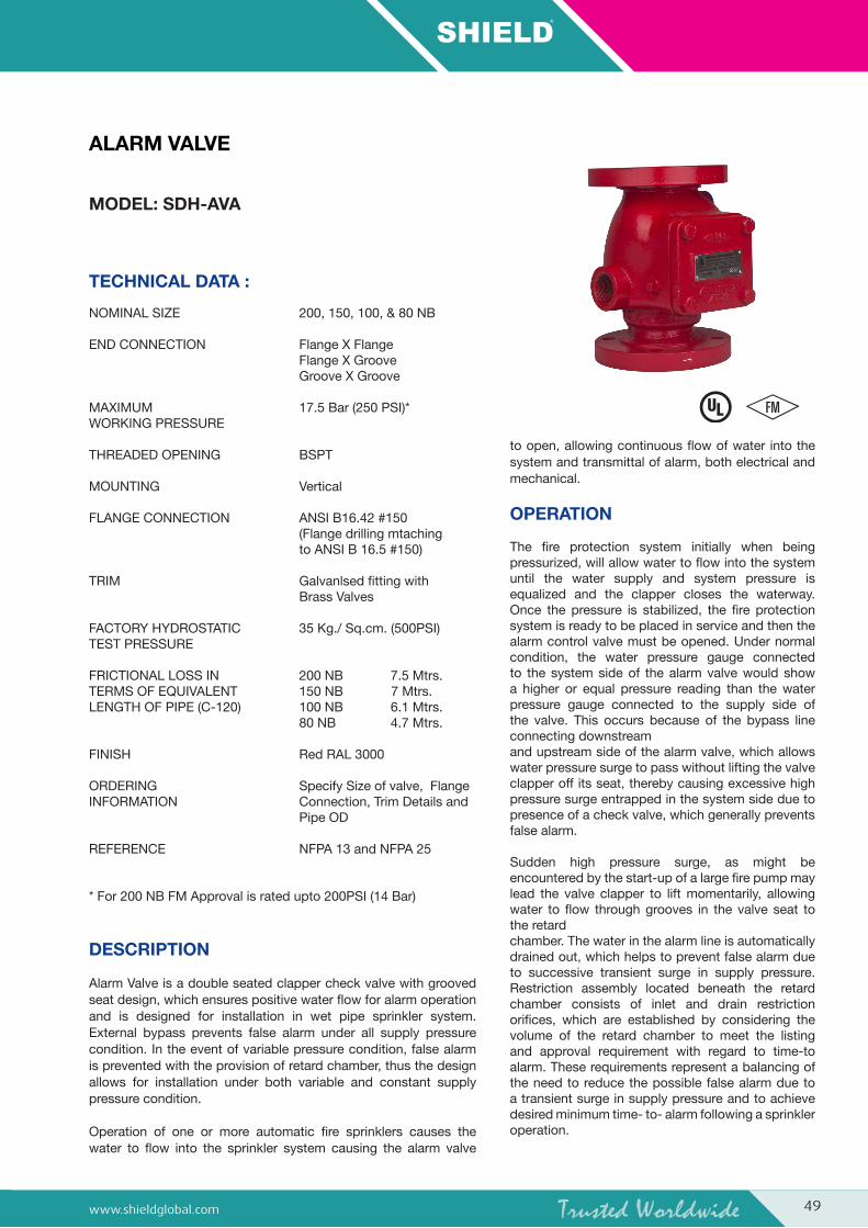
ALARM VALVE
MODEL: SDH-AVA
TECHNICAL DATA :
DESCRIPTION
Alarm Valve is a double seated clapper check valve with grooved seat design, which ensures positive water flow for alarm operation and is designed for installation in wet pipe sprinkler system. External bypass prevents false alarm under all supply pressure condition. In the event of variable pressure condition, false alarm is prevented with the provision of retard chamber, thus the design allows for installation under both variable and constant supply pressure condition.
Operation of one or more automatic fire sprinklers causes the water to flow into the sprinkler system causing the alarm valve
to open, allowing continuous flow of water into the system and transmittal of alarm, both electrical and mechanical.
OPERATION
The fire protection system initially when being pressurized, will allow water to flow into the system until the water supply and system pressure is equalized and the clapper closes the waterway. Once the pressure is stabilized, the fire protection system is ready to be placed in service and then the alarm control valve must be opened. Under normal condition, the water pressure gauge connected to the system side of the alarm valve would show a higher or equal pressure reading than the water pressure gauge connected to the supply side of the valve. This occurs because of the bypass line connecting downstreamand upstream side of the alarm valve, which allows water pressure surge to pass without lifting the valveclapper off its seat, thereby causing excessive high pressure surge entrapped in the system side due to presence of a check valve, which generally preventsfalse alarm.
Sudden high pressure surge, as might be encountered by the start-up of a large fire pump may lead the valve clapper to lift momentarily, allowing water to flow through grooves in the valve seat to the retardchamber. The water in the alarm line is automaticallydrained out, which helps to prevent false alarm due to successive transient surge in supply pressure. Restriction assembly located beneath the retard chamber consists of inlet and drain restriction orifices, which are established by considering the volume of the retard chamber to meet the listing and approval requirement with regard to time-to alarm. These requirements represent a balancing of the need to reduce the possible false alarm due to a transient surge in supply pressure and to achieve desired minimum time- to- alarm following a sprinkler operation.
NOMINAL SIZE 200, 150, 100, & 80 NB
END CONNECTION Flange X Flange Flange X Groove Groove X Groove
MAXIMUM 17.5 Bar (250 PSI)*WORKING PRESSURE
THREADED OPENING BSPT MOUNTING Vertical
FLANGE CONNECTION ANSI B16.42 #150 (Flange drilling mtaching to ANSI B 16.5 #150)
FRICTIONAL LOSS IN 200 NB 7.5 Mtrs.TERMS OF EQUIVALENT 150 NB 7 Mtrs.LENGTH OF PIPE (C-120) 100 NB 6.1 Mtrs. 80 NB 4.7 Mtrs.
FINISH Red RAL 3000
ORDERING Specify Size of valve, Flange INFORMATION Connection, Trim Details and Pipe OD
REFERENCE NFPA 13 and NFPA 25
* For 200 NB FM Approval is rated upto 200PSI (14 Bar)
50 www.shieldglobal.com
In constant pressure installation, the retard chamber is not required and the water passing through the groove in the alarm valve seat flows directly through restriction nozzle
assembly to activate the mechanical and electrical alarm.
INSTALLATION
1. SHIELD Sprinkler alarm valve, Model-SDH-AVA must be installed vertically.
2. The alarm valve must be installed in a readily visible and accessible location and provision to be made in such a way that alarm line drain is visible and accessible.
3. Where water pressure fluctuates, the variable pressure trim with retard chamber must be used. Under non-fluctuating water pressure condition, the constant pressure trim, which does not include retard chamber, may be used.
4. The valve must be installed with trim in accordance with the trim data. Failure to follow the appropriate trim connection guidelines may prevent the device from functioning properly as well as void listing, approval and the manufacturer’s warranty.
5. Care must be exercised while installing the check valve in the trim to ascertain that they are located with the arrow mark on the check valve body and pointed in proper direction.
6. The contraction and expansion associated with an excessive volume of trapped air could cause the waterway clapper to cycle open and shut. This may result in false alarm or an intermittent alarm. To avoid these, it is recommended to have breather valve in the system piping network and a vent valve at the extreme end of the system to bleed-off the air.
7. The ball valve provided on the alarm line must be kept open and strapped in set position.
8. Pipe connecting the retard chamber and sprinkler alarm bell must be supported properly to avoid loading on the retard chamber.
9. All the newly installed system pipes must be flushed properly before alarm valve is put into service.
INSPECTION AND MAINTENANCE
A qualified and trained person must commission the system. After few initial successful tests an authorised person must be trained to perform inspection and testing of the system.
It is recommended to carry out physical inspection of the system at least twice a week. The inspection should verify that all the control valves are in proper position as per the requirement of the system and no damage has taken place to any component.
It is recommended that the alarm valve and its accessories should be examined and performed for following at least
quarterly or as demanded by local authorities to ensure reliable and trouble free operation and service.
1. Inspection and testing is to be carried out only by an authorized person. DO NOT TURN OFF the water supply valve to undertake repair work or to test the valve, without placing a roving fire patrol in the area covered by the system. The patrol should continue until the system is back into service. Also do inform the local security personnel and alarm control station, so that a false alarm is not signaled.
2. Open the alarm test valve. Verify that the sprinkler alarm bell and/or the pressure alarm switch/ electric alarm properly actuate. Close the alarm test valve and verify that water has ceased to flow from the alarm line drain.
3. Clean the 20 NB (3/4”) strainer provided on the sprinkler alarm bell line.
4. Clean the strainer of restriction assembly.
5. Inspect the check valve clapper located on the bypass line.
FALSE ALARM
1. Inspect the valve rubber clapper face. If worn or damaged, replace it. Be certain that dirt, stone or any other foreign object have not accumulated under the clapper face and lodged in the groove or holes. Clean the clapper face thoroughly. If the seat ring surface is nicked or scoured, it might be possible to repair the same using lapping compound. If not, replace the complete valve or return it to the manufacturer’s works for repair.
2. If sprinkler alarm bell is not functioning or the impeller is jammed, please follow the maintenance guideline provided in the catalogue for sprinkler alarm bell.
3. If pressure alarm switch gives a steady signal, but sprinkler alarm generates an intermittent alarm, check sprinkler alarm bell shaft. If both the sprinkler alarm bell and pressure alarm switch are generating intermittent alarm then check for the possible air which is trapped within the sprinkler system. Trapped air is to be bled off. Also the intermittent alarm may occur due to sudden pressure drop and increase in the system. These problems can be corrected by maintaining a steady supply.
CAUTION
1. The UL Listing, FM Approval and manufacturer’s warranty are valid only when the alarm valve is installed with trim set and installed as per installation guidelines.
2. Pressure relief valve is required with wet pipe system, when a rise in ambient temperature can cause system pressure to exceed 17.5 Bar (250 PSI). A 17.7 Bar relief valve setting should be used.
3. For proper operation of the wet system and to minimize unwanted false alarm, it is important to remove trapped air from the system. The air trapped in the system may also cause intermittent operation of the Water Motor Alarm during sustained flow of water.
51www.shieldglobal.com
NOMINAL PRESSURE LOSS VS FLOW
Valve Size Flange x Flange
Flange x Groove
Groove x Groove
200 65 54 44
150 42 35.8 28
100 27 22.1 17.3
80 18 15 12.1
Normal Size Pipe OD in MM
80 NB 89
100 NB 114.3
150 NB 165.1
150 NB 168.3
200 NB 219.1
WEIGHT IN KG GROOVE PIPE SIZE
Note: For 150 NB standard supply is 168.3 mm OD pipe Groove. For 165.1mm specify in order.
52 www.shieldglobal.com
ALARM VALVE, MODEL – SDH-AVA
PART LIST
PART NO. QTY.
ITEM 200NB
150NB
100NB
80NB
DESCRIPTION 200NB
150NB
100NB
80NB
MATERIALSPECIFICATION
1 NA NA NA NAHousing (Flange x Flange)
1 1 1 1 Ductile Iron
1 AV2014 AV1514 AV1014 AV8014Housing (Flange x Groove)
1 1 1 1 Ductile Iron
1 AV2014 AV1515 AV1015 AV8015Housing (Groove x Groove)
When pressure switch is supplied thenSl.No. 22 plug not required.
54 www.shieldglobal.com
CONSTANT PRESSURE TRIM FOR ALARM VALVE
1 AV01 Hex Nipple �” 4 4 5 2
2 AV02 Tee �” 3 3 3 2
3 AV03/1 Elbow �” 2 2 2 ---
3 AV03/2 Elbow ½” --- --- --- 2
4 AV04/1 Pipe Nipple �” X 150 mm Long 1 --- --- ---
4 AV04/2 Pipe Nipple �” X 130 mm Long --- 1 --- ---
4 AV04/3 Pipe Nipple �” X 100 mm Long --- --- 1 ---
4 AV04/4 Pipe Nipple ½” X 100 mm Long --- --- --- 1
5 AV05/1 Pipe Nipple �” X 100 mm Long 1 --- --- ---
5 AV05/2 Pipe Nipple �” X 80 mm Long --- 1 --- ---
6 AV06/1 Pipe Nipple ½” X 100 mm Long 1 --- --- 1
6 AV06/2 Pipe Nipple ½” X 80 mm Long --- 1 1 ---
7 AV07/1 Union �” 1 1 1 ---
7 AV07/2 Union ½” --- --- --- 1
8 AV08/1 Swing Check Valve �” 1 1 1 ---
8 AV08/2 Swing Check Valve ½” --- --- --- 1
9 AV09/1 Pipe Nipple �” X 70 mm Long 1 1 --- ---
9 AV09/2 Pipe Nipple �” X 60 mm Long --- --- 1 ---
9 AV09/3 Pipe Nipple ½” X 70 mm Long --- --- --- 1
10 AV10 Ball Valve ½” 2 2 2 2
11 AV11 Reducing Hex Nipple �” X ½” --- --- --- 1
12 AV12 Reducing Hex Nipple �” X ¼” 1 1 1 1
13 AV13 Reducing Hex Nipple ½” X ¼” 1 1 1 1
14 AV14 Ball Valve ¼” 2 2 2 2
15 AV15 Hex Nipple ¼” 2 2 2 2
16 AV16 Elbow ¼” 2 2 2 2
17 AV17 Pressure Gauge ¼” 2 2 2 2
18 AV18/1 Alarm Test Line Assembly ½” --- --- --- 1
18 AV18/2 Alarm Test Line Assembly ½” --- --- 1 ---
18 AV18/3 Alarm Test Line Assembly ½” --- 1 --- ---
18 AV18/4 Alarm Test Line Assembly ½” 1 --- --- ---
19 AV19 Reducing Bush �” X ½” 2 2 2 1
20 AV20 Restriction Nozzle Assembly --- 1 1 1 1
21 AV21 Y Type Strainer �” 1 1 1 1
22 AV22 Plug ½” 1 1 1 1
23 AV23/1 Sprinkler Alarm --- 1 1 1 1
23 AV23/2 Sprinkler Alarm --- 1 1 1 1
24 AV24/1 Hex Nipple 2” 1 1 1 ---
24 AV24/2 Hex Nipple 1¼” --- --- --- 1
25 AV25/1 Angle Valve 2” 1 1 1 ---
25 AV25/2 Angle Valve 1¼” --- --- --- 1
26 AV26 Pipe Nipple ½” X 60 mm Long 2 2 2 2
27 AV27 Pipe Nipple �” X 80 mm Long 1 1 1 1
28 AV28 Hex Nipple ½” 3 3 3 5
29 AV29 Tee ½” 2 2 2 3
30 AV30 Pressure Switch (Optional) ½” 1 1 1 1
ITEM NO.
CODE NO.
DESCRIPTION SIZEQTY
200NB 150 NB 100 NB 80 NB
55www.shieldglobal.com
VARIABLE PRESSURE TRIM FOR ALARM VALVE
30
1
#
2
2
1613
15
14
10
8
12
21
1
63
54
1615
1424
25
NO
NC
NO
NO
2
21
23
#
#
#
#
22
11
17
10
9
18
1926
19
27
@
1
31
#
29
28
29
1613
15
14
10
8
12
21
1
63
5
3
7
2,29
4
1615
1424
25
NO
NC
NO
NO
2
21
23
32 #
#
#
#
1,28
22
11
17
10
9
18
1926
19
27
@
28
1,28
28
20
# 26
20
# 26
DD
D
D
GROOVE X GROOVE FLANGE X GROOVE
FLANGE X FLANGE
#
#
#
*
Optional Trim
Drain
To suit at site by installer
Normally Open
Normally Closed
Notes
When pressure switch is supplied thenSl.No. 22 plug not required.
56 www.shieldglobal.com
VARIABLE PRESSURE TRIM FOR ALARM VALVE
1 AV01 Hex Nipple �” 4 4 5 2
2 AV02 Tee �” 3 3 3 2
3 AV03/1 Elbow �” 2 2 2 ---
3 AV03/2 Elbow ½” --- --- --- 2
4 AV04/1 Pipe Nipple �” X 150 mm Long 1 --- --- ---
4 AV04/2 Pipe Nipple �” X 130 mm Long --- 1 --- ---
4 AV04/3 Pipe Nipple �” X 100 mm Long --- --- 1 ---
4 AV04/4 Pipe Nipple ½” X 100 mm Long --- --- --- 1
5 AV05/1 Pipe Nipple �” X 100 mm Long 1 --- --- ---
5 AV05/2 Pipe Nipple �” X 80 mm Long --- 1 --- ---
6 AV06/1 Pipe Nipple ½” X 100 mm Long 1 --- --- 1
6 AV06/2 Pipe Nipple ½” X 80 mm Long --- 1 1 ---
7 AV07/1 Union �” 1 1 1 ---
7 AV07/2 Union ½” --- --- --- 1
8 AV08/1 Swing Check Valve �” 1 1 1 ---
8 AV08/2 Swing Check Valve ½” --- --- --- 1
9 AV09/1 Pipe Nipple �” X 70 mm Long 1 1 --- ---
9 AV09/2 Pipe Nipple �” X 60 mm Long --- --- 1 ---
9 AV09/3 Pipe Nipple ½” X 70 mm Long --- --- --- 1
10 AV10 Ball Valve ½” 2 2 2 2
11 AV11 Reducing Hex Nipple �” X ½” --- --- --- 1
12 AV12 Reducing Hex Nipple �” X ¼” 1 1 1 1
13 AV13 Reducing Hex Nipple ½” X ¼” 1 1 1 1
14 AV14 Ball Valve ¼” 2 2 2 2
15 AV15 Hex Nipple ¼” 2 2 2 2
16 AV16 Elbow ¼” 2 2 2 2
17 AV17 Pressure Gauge ¼” 2 2 2 2
18 AV18/1 Alarm Test Line Assembly ½” --- --- --- 1
18 AV18/2 Alarm Test Line Assembly ½” --- --- 1 ---
18 AV18/3 Alarm Test Line Assembly ½” --- 1 --- ---
18 AV18/4 Alarm Test Line Assembly ½” 1 --- --- ---
19 AV19 Reducing Bush �” X ½” 2 2 2 1
20 AV20 Restriction Nozzle Assembly --- 1 1 1 1
21 AV21 Y Type Strainer �” 1 1 1 1
22 AV22 Plug ½” 1 1 1 1
23 AV23/1 Sprinkler Alarm --- 1 1 1 1
23 AV23/2 Sprinkler Alarm --- 1 1 1 1
24 AV24/1 Hex Nipple 2” 1 1 1 ---
24 AV24/2 Hex Nipple 1¼” --- --- --- 1
25 AV25/1 Angle Valve 2” 1 1 1 ---
25 AV25/2 Angle Valve 1¼” --- --- --- 1
26 AV26 Pipe Nipple ½” X 60 mm Long 2 2 2 2
27 AV27 Pipe Nipple �” X 80 mm Long 1 1 1 1
28 AV28 Hex Nipple ½” 3 3 3 5
29 AV29 Tee ½” 2 2 2 3
30 AV30 Pressure Switch (Optional) ½” 1 1 1 1
31 AV31 Retard Chamber, Model - RC9 --- 1 1 1 1
32 AV32 Hex Nipple �” 1 1 1 1
ITEM NO.
CODE NO.
DESCRIPTION SIZEQTY
200NB 150 NB 100 NB 80 NB
57www.shieldglobal.com
CONSTANT PRESSURE TRIM - SCHEMATICFLANGE X FLANGE
VARIABLE PRESSURE TRIM - SCHEMATICFLANGE X FLANGE
NOTE:-1) Sprinkler alarm control valve must be kept normally open if this valve is kept closed the sprinkler alarm bell/electric alarm will not signal.
2) Sprinkler alarm test valve must be kept normally closed condition. Valve is opened to test the sprinkler alarm bell/ electrical alarm.
AT
TO DRAIN
AC
PGPG
PS
SYSTEMPRESSURE SUPPLY
PRESSURE
UPSTREAM.(FROM SUPPLY)
DOWNSTREAM.(TO SYSTEM)
TO DRAIN~
G
**
AT
TO DRAIN
AC
RC
PGPG
PS
SYSTEMPRESSURE SUPPLY
PRESSURE
UPSTREAM.(FROM SUPPLY)
DOWNSTREAM.(TO SYSTEM)
TO DRAIN~
G
**
Abbreviation & Symbols
Non Return Valve
Valve
Angle Valve
Strainer
NC Normally Closed
Restriction Nozzle Assembly
Stop Valve
AC Sprinkler Alarm Control Valve
Optional
NO Normally Open
OD Open Drain
PG Pressure Gauge
AV Alarm Valve
G Sprinkler Alarm
PS Pressure Switch
RC Retard Chamber
AT Sprinkler Alarm Test Valve
--- By User
58 www.shieldglobal.com
CONSTANT PRESSURE TRIM - SCHEMATICFLANGE X GROOVE
VARIABLE PRESSURE TRIM - SCHEMATICFLANGE X GROOVE
NOTE:-1) Sprinkler alarm control valve must be kept normally open if this valve is kept closed the sprinkler alarm bell/electric alarm will not signal.
2) Sprinkler alarm test valve must be kept normally closed condition. Valve is opened to test the sprinkler alarm bell/ electrical alarm.
AT
TO DRAIN
AC
PGPG
PS
SYSTEMPRESSURE SUPPLY
PRESSURE
UPSTREAM.(FROM SUPPLY)
DOWNSTREAM.(TO SYSTEM)
TO DRAIN~
G
**
AT
TO DRAIN
AC
RC
PGPG
PS
SYSTEMPRESSURE SUPPLY
PRESSURE
TO DRAIN~
G
**
Abbreviation & Symbols
Non Return Valve
Valve
Angle Valve
Strainer
NC Normally Closed
Restriction Nozzle Assembly
Stop Valve
AC Sprinkler Alarm Control Valve
Optional
NO Normally Open
OD Open Drain
PG Pressure Gauge
AV Alarm Valve
G Sprinkler Alarm
PS Pressure Switch
RC Retard Chamber
AT Sprinkler Alarm Test Valve
--- By User
59www.shieldglobal.com
CONSTANT PRESSURE TRIM - SCHEMATICGROOVE X GROOVE
VARIABLE PRESSURE TRIM - SCHEMATICGROOVE X GROOVE
NOTE:-1) Sprinkler alarm control valve must be kept normally open if this valve is kept closed the sprinkler alarm bell/electric alarm will not signal.
2) Sprinkler alarm test valve must be kept normally closed condition. Valve is opened to test the sprinkler alarm bell/ electrical alarm.