Scroll Compressors - Comfort - Refrigeration 2 -Subcritical Refrigeration Semi-Hermetic Reciprocating Compressors - S-Series Reciprocating Compressor Range Condensing Units Compressor Motor Codes Table Controls - Electronic Controllers and Sensors - Pressure Controls and Thermostats 3 22 26 52 56 62 66 229
Transcript
Scroll Compressors
- Comfort
- Refrigeration
2-Subcritical Refrigeration
Semi-Hermetic Reciprocating Compressors
- S-Series Reciprocating Compressor Range
Condensing Units
Compressor Motor Codes Table
Controls
- Electronic Controllers and Sensors
- Pressure Controls and Thermostats
3
22
26
52
56
62
66
229
123
Alco Controls
Alco Controls is the leading provider of precision electronic
and electromechanical controls for the refrigeration and air
conditioning markets. We continue to pioneer the control
of refrigerant flow with innovative designs, keeping system
performance optimization central to our product development.
The wide range of Emerson controllers covers all major
applications in commercial air conditioning and refrigeration, as
well as heat pump systems. There are stand alone controllers and
controllers with a communication interface, which can be used in
LON networked systems too.
The controllers with TCP/IP Ethernet communication feature a
full web server function and provide full data exchange with any
user in the World Wide Web. This allows quick and inexpensive
monitoring from any PC with a standard web browser.
Emerson offers drivers and superheat controllers designed
for the EX4 to EX8 range of electrically driven control valves.
The superheat controllers allow stable superheat control with
the EX valves, while the digital superheat controllers can be
synchronized with the PWM capacity control valve incorporated
in the Digital Scroll™ compressor technology.
Display case and cold room controllers provide all functions
needed to run commercial refrigeration, like superheat control
with electrical control valve, thermostat, fan and defrost control,
integrated timer and alarm functions.
Other controllers offer control functions on the “hot side” of the
refrigeration circuit: condenser and condensing unit controllers,
rack controllers for up to 8 single stage compressors or for multi-
stage compressors and dual circuit controllers.
The compressor soft starter allows keeping the starting current
below the limit imposed in residential heat pump applications.
Electronic fan speed controllers help to maintain a minimum
condensing pressure by reducing fan speed at low ambient
temperature.
Sensors and accessories are needed in conjunction with the
above mentioned controllers.
Oil management systems are used to maintain the oil level in the
compressor’s crank case.
Emerson´s controls portfolio is completed by offering a variety of
mechanical controls such as:
- pressostats & thermostats,
- system protectors,
- valves,
- thermo™-Expansion Valves,
- oil separators,
- and Suction Accumulators.
Whatever control you choose, you can always expect high
reliability and best performance.
124
Alco Keyword Register
Series Description Page
110 RB 2-Way Solenoid Valve 222
200 RB 2-Way Solenoid Valve 222
240 RA 2-Way Solenoid Valve 222
540 RA 2-Way Solenoid Valve 223
935 Liquid Injection Valve 213
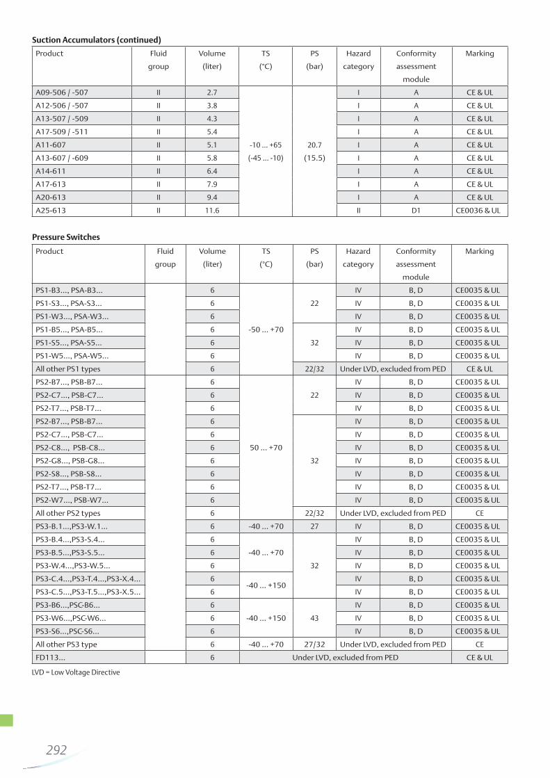
A Suction Accumulator 282
ACP Hot Gas Bypass Regulator 231
ADK Filter Drier 256
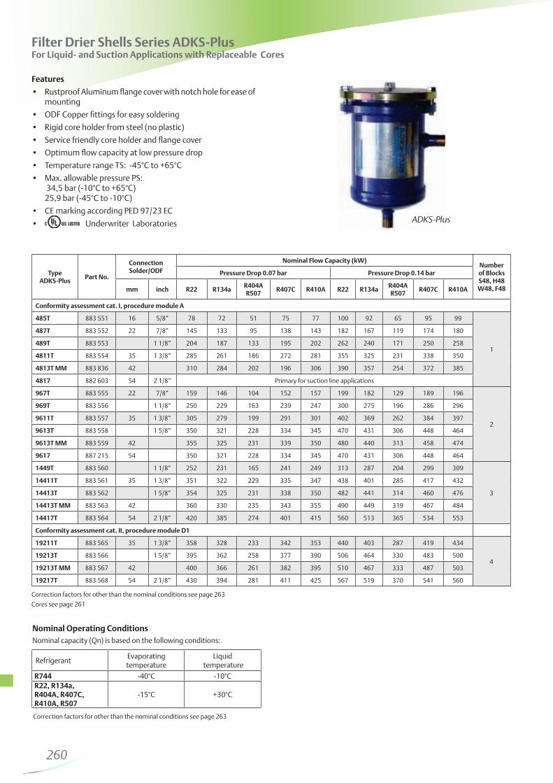
ADKS-Plus Filter Drier Shell 260
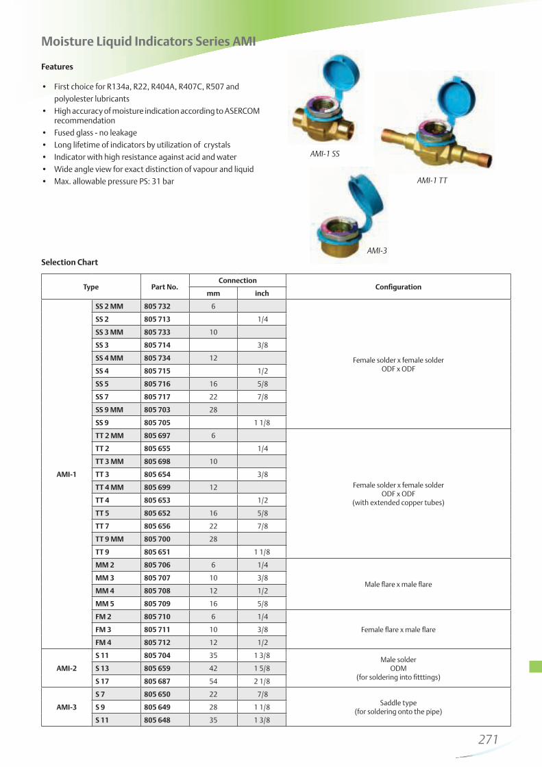
AMI Moisture Liquid Indicator 271
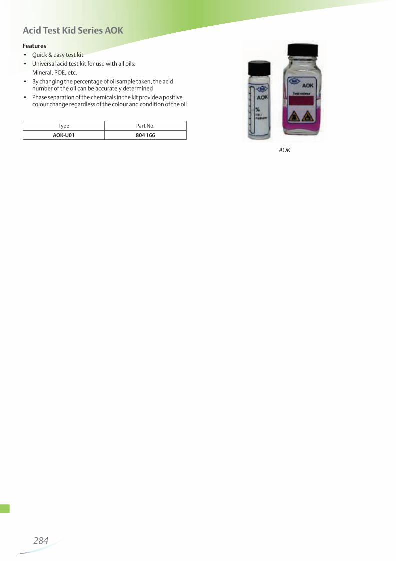
AOK Acid Alert Kit 284
ASF Suction Line Filter 266
ASD Suction Line Filter Drier 266
B
BFK Bi-Flow Filter Drier 255
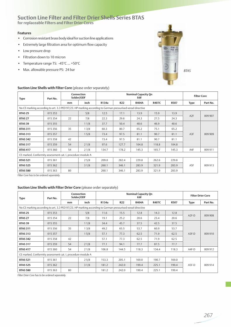
BTAS Suction Line Filter Drier Shell 267
BVE / BVS Ball Valves 283
C
CPHE Hot Gas Bypass Regulator 232
CSS Compressor Soft Starter 181
CX4 .. CX7 High Pressure Expansion Valves 153
E
EC2-1, -2, -3 Display Case Controller 165
EC2-5, -7 Condenser- , CU-Controller 165
EC3-3 Coldroom Controller 168
EC3-6 ... -9 Rack and Condenser Controller 168
EC3-D12/D23 Driver for Digital Copeland™ compressors 179
EC3-D72/D73 Digital Superheat Controllers 160
EC3-X32/X33 Superheat Controllers 160
EX2 Pulse Modulated Expansion Valve 130
EX4 .. EX8 Electrical Control Valves 133
EXD-HP1/2 Superheat Economizer Controller 158
EXD-U Stand-alone Univ. Driver Module 164
EXM/EXL Electrical Control Valves 129
125
Alco Keyword Register
Series Description Page
F
FD 113 Differential Pressure Switch 247
FDB Filter Drier 258
FDH Filter Drier Shell 261
FDS-24 Filter Drier Shell 262
FSE Fan Speed Control Module 186
FSY Electronic Fan Speed Controller 184
L Liquid Injection Valve 186
M
M36 3-Way Solenoid Valve 227
MIA Moisture Liquid Indicator 270
O
OM3 / OM4 Oil Level Management System 275
OW4 Electronic Oil Level Monitoring 278
OS Oil Separator 279
P
PRC Crankcase Pressure Regulator 235
PRE Evaporator Pressure Regulator 234
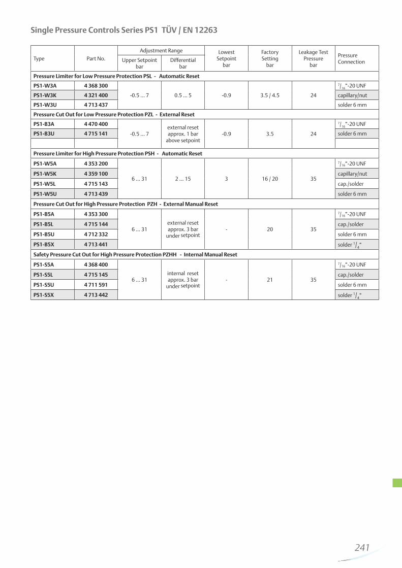
PS1 Pressure Controls 240
PS2 Dual Pressure Controls 242
PS3 Pressure Controls 244
PT5 Pressure Transmitter 182
T Thermo™-Expansion Valve 202
TI Thermo™ Expansion Valve 190
TS1 Thermostat 250
TX3 Thermo™ ExpansionValve 198
TX6 Thermo™ Expansion Valve 200
Z
ZZ Thermo™ -Expansion Valve 208
126
Electrical Control Valves
127
128
Electrical Control Valves
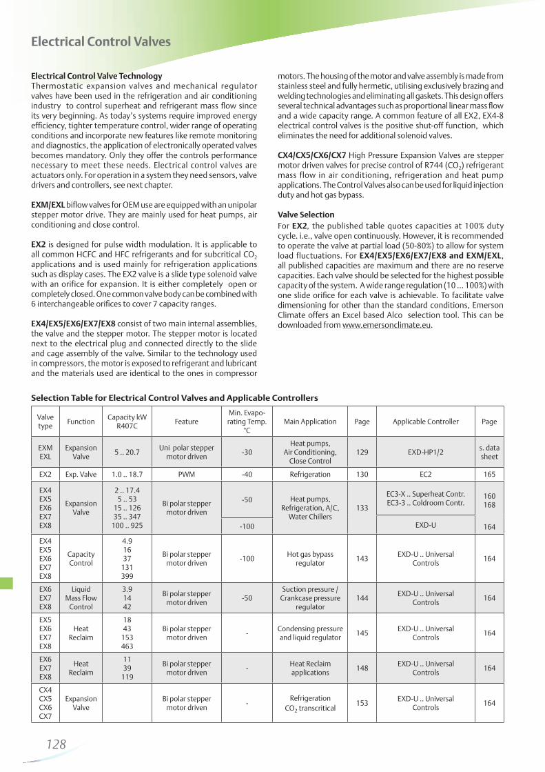
Electrical Control Valve TechnologyThermostatic expansion valves and mechanical regulator valves have been used in the refrigeration and air conditioning industry to control superheat and refrigerant mass flow since its very beginning. As today’s systems require improved energy efficiency, tighter temperature control, wider range of operating conditions and incorporate new features like remote monitoring and diagnostics, the application of electronically operated valves becomes mandatory. Only they offer the controls performance necessary to meet these needs. Electrical control valves are actuators only. For operation in a system they need sensors, valve drivers and controllers, see next chapter.
EXM/EXL biflow valves for OEM use are equipped with an unipolar stepper motor drive. They are mainly used for heat pumps, air conditioning and close control.
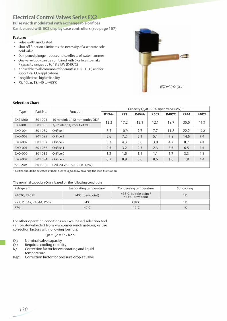
EX2 is designed for pulse width modulation. It is applicable to all common HCFC and HFC refrigerants and for subcritical CO2 applications and is used mainly for refrigeration applications such as display cases. The EX2 valve is a slide type solenoid valve with an orifice for expansion. It is either completely open or completely closed. One common valve body can be combined with 6 interchangeable orifices to cover 7 capacity ranges.
EX4/EX5/EX6/EX7/EX8 consist of two main internal assemblies, the valve and the stepper motor. The stepper motor is located next to the electrical plug and connected directly to the slide and cage assembly of the valve. Similar to the technology used in compressors, the motor is exposed to refrigerant and lubricant and the materials used are identical to the ones in compressor
motors. The housing of the motor and valve assembly is made from stainless steel and fully hermetic, utilising exclusively brazing and welding technologies and eliminating all gaskets. This design offers several technical advantages such as proportional linear mass flow and a wide capacity range. A common feature of all EX2, EX4-8 electrical control valves is the positive shut-off function, which eliminates the need for additional solenoid valves.
CX4/CX5/CX6/CX7 High Pressure Expansion Valves are stepper motor driven valves for precise control of R744 (CO2) refrigerant mass flow in air conditioning, refrigeration and heat pump applications. The Control Valves also can be used for liquid injection duty and hot gas bypass.
Valve Selection
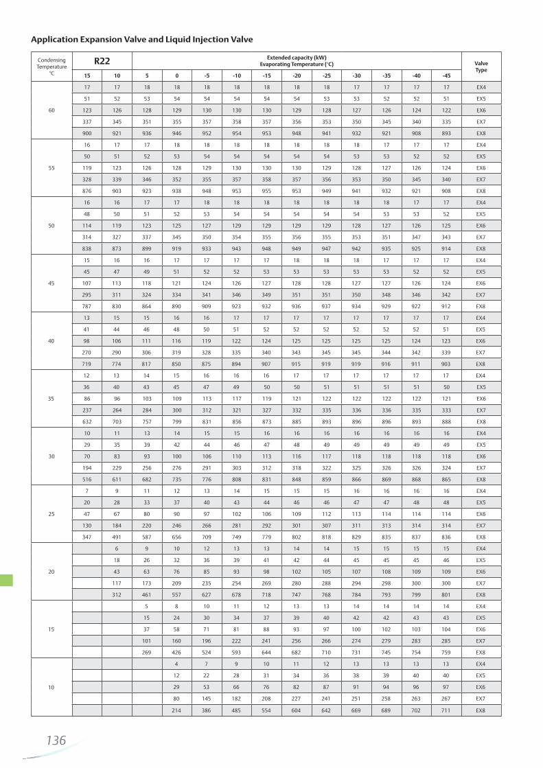
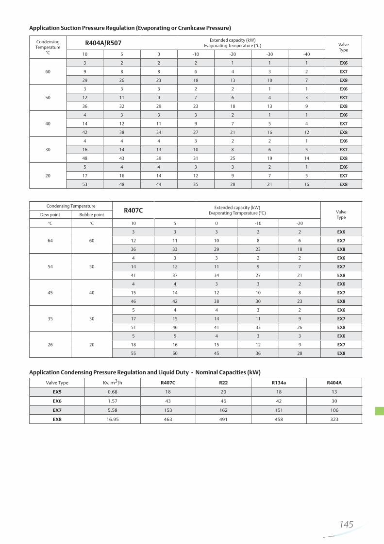
For EX2, the published table quotes capacities at 100% duty cycle. i.e., valve open continuously. However, it is recommended to operate the valve at partial load (50-80%) to allow for system load fluctuations. For EX4/EX5/EX6/EX7/EX8 and EXM/EXL, all published capacities are maximum and there are no reserve capacities. Each valve should be selected for the highest possible capacity of the system. A wide range regulation (10 … 100%) with one slide orifice for each valve is achievable. To facilitate valve dimensioning for other than the standard conditions, Emerson Climate offers an Excel based Alco selection tool. This can be downloaded from www.emersonclimate.eu.
Selection Table for Electrical Control Valves and Applicable Controllers
For other operating conditions an Excel based selection tool can be downloaded from www.emersonclimate.eu, or use correction factors with following formula:
Qn = Qo x Kt x K∆p
Qn: Nominal valve capacity
Qo: Required cooling capacity
Kt: Correction factor for evaporating and liquid
temperatureK∆p: Correction factor for pressure drop at valve
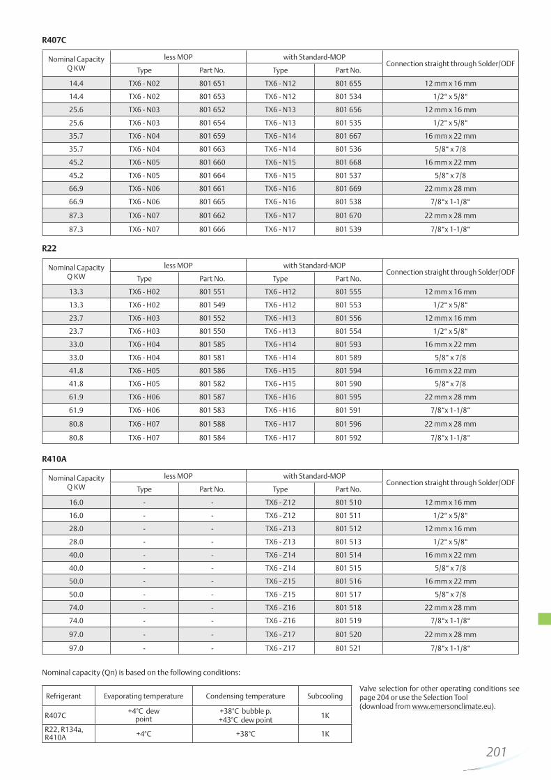
The nominal capacity (Qn) is based on the following conditions:
Refrigerant Evaporating temperature Condensing temperature Subcooling
R407C, R407F +4°C (dew point) +38°C bubble point /+43°C dew point 1K
* Biflow versions are not released for R124 and R23 Capacity for biflow versions identical in both flow directions.
The nominal capacity (Qn) is based on the following conditions:
Refrigerant Evaporating temperature Condensing temperature Subcooling
R407C, R407F +4°C (dew point) +38°C bubble point /+43°C dew point 1K
R22, R134a, R404A, R410A +4°C +38°C 1K
R124 +20°C +80°C 1K
R23 -60°C -25°C 1K
R744 -40°C -10°C 1K
Guideline for Selection of Electrical Control Valves as Expansion Valves
Alco Selection Tool
For easy and quick selection of Electrical Control Valves an Excel
based selection tool can be downloaded from the Internet at
www.emersonclimate.eu, or use the quick selection tables on
the following pages.
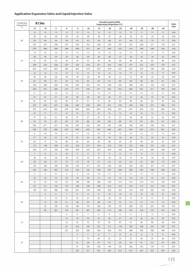
The following guideline should be taken into consideration in order to obtain full advantages of the control valves:
- Published capacities are maximum and there are no reserve capacities
- Larger size of valve leads to shorter pull down period and
shorter travel time i.e., faster response. For example,
EX7 has maximum 3.2 seconds travel time. The valve has
approximately 1.6 seconds travel time at 50% capacity
operation.
For controllers, see page 152, 153 and 157.
Example:System with R407C having two different operating conditions:A) 110 kW capacity at +4°C/+50°C with two stages compressor at 50% / 100% capacityB) 137 kW capacity at +4°C/+30°C with two stages compressor at 50% / 100% capacityEX6 with 126 kW covers condition A, however is not sufficient to cover condition B. It is recommended to select larger valve i. e. EX7 with 337 kW at condition A and 293 kW at condition B.
Condition A:
Full load ratio = 110 / 337 = 33%
Partial load ratio = (110/2) / 337 = 16%
Condition B:
Full load ratio = 137 / 293 = 47%
Partial load ratio = (137/2) / 293 = 23%
The capacity ratios of system to valve are in all conditions higher than 10%. It is recommended to use EX7 rather than EX6.
135
Application Expansion Valve and Liquid Injection Valve
Type Part No. Temperature Range Length Connector type to valveConnector type to driver
or controllerIllustration
EXV-M15 804 663
-50 … +80°C
1.5 m
M12, 4 pins Loose wiresEXV-M30 804 664 3.0 m
EXV-M60 804 665 6.0 m
Emerson Climate Technologies CX series are stepper motor driven valves for precise control of R744 (CO2) refrigerant mass flow in air conditioning, refrigeration, heat pump ap-plications. The Control Valves can be used as high pressure expansion valve, liquid injection duty, hot gas bypass.
153
154
Electronic Controllers and Sensors
155
Electronic Controllers and Sensors
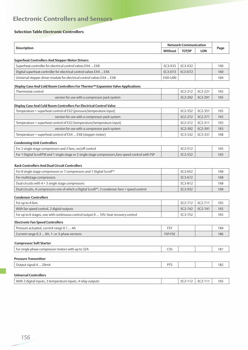
Selection Table Electronic Controllers
DescriptionNetwork Communication
PageWithout TCP/IP LON
Superheat controller for electrical control valves EX4 … EX8 EC3-X33 EC3-X32 160
Digital superheat controller for electrical control valves EX4 … EX6 EC3-D73 EC3-D72 160
Universal stepper driver module for electrical control valves EX4 … EX8 EXD-U00 164
With 2 digital inputs, 3 temperature inputs, 4 relay outputs EC2-112 EC2-111 165
Output signal 4 … 20mA PT5 182
For single phase compressor motors with up to 32A CSS 181
Pressure actuated, current range 0.1 … 4A FSY 184
Current range 0.3 … 8A, 1- or 3-phase versions FSP-FSE 186
For up to 4 fans EC2-712 EC2-711 165
With fan speed control, 2 digital outputs EC2-742 EC2-741 165
For up to 6 stages, one with continuous control output 0 … 10V, heat recovery control EC3-752 165
For 8 single stage compressors or 7 compressors and 1 Digital ScrollTM EC3-652 168
For multistage compressors EC3-672 168
Dual circuits with 4 + 3 single stage compressors EC3-812 168
Dual circuits, 4 compressors one of which a Digital ScrollTM, 3 condenser fans + speed control EC3-932 168
For 2 single stage compressors and 2 fans, on/off control EC2-512 165
For 1 Digital ScrollTM and 1 single stage or 2 single stage compressors,fans speed control with FSP EC2-552 165
Temperature + superheat control of EX2 (pressure/temperature input) EC2-352 EC2-351 165
version for use with a compressor pack system EC2-272 EC2-271 165
Temperature + superheat control of EX2 (temperature/temperature input) EC2-312 EC2-311 165
version for use with a compressor pack system EC2-392 EC2-391 165
Temperature + superheat control of EX4 … EX8 (stepper motor) EC3-332 EC3-331 168
Thermostat control EC2-212 EC2-221 165
version for use with a compressor pack system EC2-292 EC2-291 165
Display Case And Cold Room Controllers For Thermo™ Expansion Valve Applications
Display Case And Cold Room Controllers For Electrical Control Valve
Condensing Unit Controllers
Rack Controllers And Dual Circuit Controllers
Condenser Controllers
Electronic Fan Speed Controllers
Compressor Soft Starter
Pressure Transmitter
Universal Controllers
Superheat Controllers And Stepper Motor Drivers
156
Emerson Climate Technologies designed superheat controllers and valve drivers for stepper motor driven control valves for all commercial refrigeration and air conditioning applications.
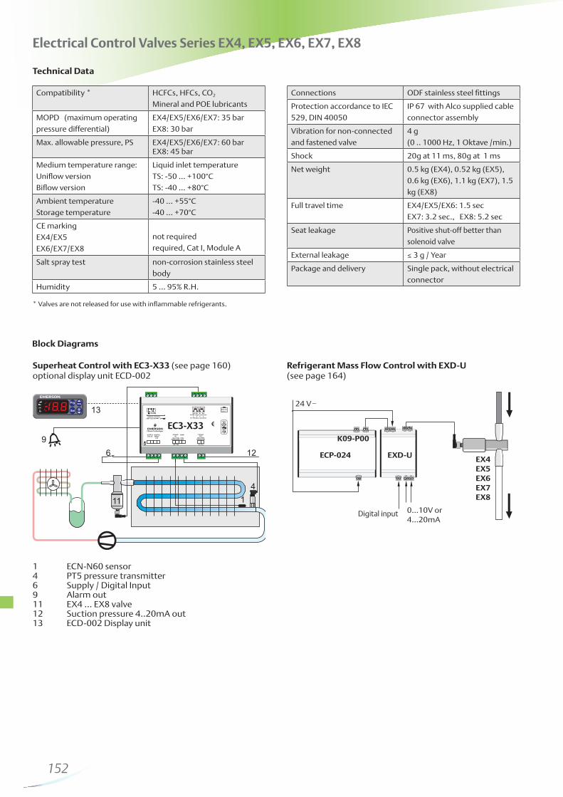
EC3-X33 is a universal superheat controller without network communication for air conditioning, refrigeration and industrial applications such as chillers, industrial process cooling, rooftops, heat pumps, package unit, close control, cold room, food process and air driers. The ECD-002 Display/keypad Unit is necessary for setup but not for operation of the controllers. ECD-002 can be connected or disconnected to EC3-X33 at any time.
In the event of a cooling request and compressor start-up, EC3-X33 needs to be informed. This can be achieved by a digital input. EC3-X33 will start to control the refrigerant mass flow stand-alone by precise positioning of the Control Valve under different operating conditions such as compressor start-up, start of a further compressor, high head pressure, low head pressure, high load, low load and partial load operation. EC3-X33 is capable for diagnostics and alarm. The alarm can be received via relay output as well as optical LED/alarm code on ECD-002.
The EC3-X32 has a similar function as EC3-X33 but with a TCP/IP Ethernet communication interface enabling the controller to be directly connected to a network or a PC via the standard Ethernet port. The EC3-X32 controller has embedded WebPages to enable the user to visualise the parameter list with a standard WebBrowser
like Internet Explorer®. When connected to a suitable connection, the controller is able to automatically send alarms by email to a PC or mobile phone.
For use with Copeland Scroll™ Digital technology two other models are available. EC3-D73 is a stand-alone version for use with the ECD-002 Display / Keypad unit whilst the EC3-D72 has a TCP/IP Ethernet interface. A 0-10V demand signal is required from a third party controller to control a tandem system with one fixed and one digital compressor. A patented algorithm synchronises the operation of the PWM digital compressor valve and the EX series electrical control valve.
EXD-U Universal Drivers are stepper motor drivers and enable the operation of ALCO® stepper motor driven valves EX4 ... EX8 as electronic expansion valve, capacity control by means of hot gas bypass or evaporating pressure regulator, crankcase pressure regulator, condenser pressure regulator, liquid level and liquid injection.
The universal driver module can be connected to any controller which can provide a 4-20mA or 0-10V analogue signal. The output is the opening/closing of EX4 ... EX8 and consequently the control of the refrigerant liquid or vapour mass flow in accordance with the analogue input.
Electronic Superheat Controllers and Stepper Motor Drivers
Display Case and Coldroom Controllers
The compact EC2 series is available with either TCP/IP or LON communication protocols and also covers applications where the display cases are connected to a multiple compressor application. In this case, the dedicated compressor relay on the controller is no longer required and is available as a spare relay to perhaps switch the display case lighting. The controllers therefore can be split into two groups; controller is required to switch the compressor directly; integral application and those connected to a multiple compressor (rack) system.
The EC2-21x, EC2-31x and EC2-35x have the dedicated compressor relay.
The EC2-29x, EC2-39x and EC2-37x are for use with the rack system.
The EC2-2XX series of controllers are specifically designed for display cases for use with TXV. The controller performs the function of thermostat, defrost and fan management and is capable of operating a standalone condensing unit or being incorporated into a distributed system controlled by a rack.
The EC2-3XX series incorporate the functionality of the EC2-200 model but additionally have a superheat algorithm to control the EX2 control valve:
EC2-31x / EC2-39x (Temp / Temp): the superheat is controlled using two temperature sensors.
EC2-35x / EC2-37x (Pressure / Temp): the superheat is controlled using a pressure transmitter (PT5 series) in conjunction with a temperature sensor.
Whilst the products were developed for display cases, they may also be applied to control a simple coldroom.
In principle, the EC3 series utilize the same software technology of the EC2 series but provide additional inputs and outputs to satisfy the requirements of even the most demanding systems. Like the EC2, the EC3 series may be connected together to form larger systems combining the control of multiple compressors and fans.
The optional ECD-001 Display/keypad Unit is available to display the system temperatures, indicate system status and to modify parameters.
The EC3-3XX series are specifically for use with stepper valve series (EX4, EX5, EX6, EX7, EX8). In case of power loss, the Electrical Control Valve needs to be closed to avoid flooding of the compressor, therefore each valve requires a battery backup. For this reason, the battery, together with its automatic charging circuit, has been incorporated into the controller housing, significantly saving installation time as well as space in the electrical enclosure.
157
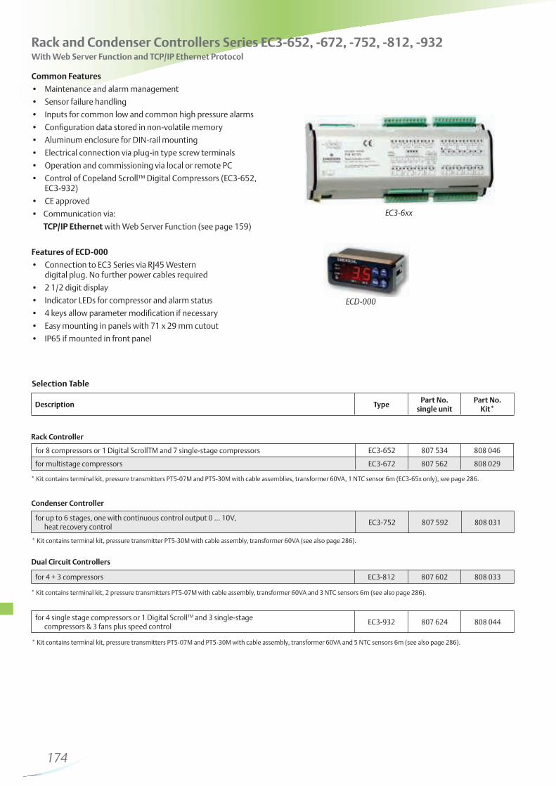
Condensing Units, Rack and Condenser Controllers
Condensing Unit Controllers
The EC2-500 series of controllers are suitable for controlling the compressors and fans of a condensing unit. Digital inputs are available for individual compressor feedback loops from the safety chain, which typically consists of low and high pressure switches together with motor protection and oil management controls. A common feedback is also available for the fans.
Following models are available:
EC2-512: to control up to 2 compressors (on/off control) and 2 fans (on/off control).
EC2-552: to control up to 2 single stage compressors or tandem compressor condensing units with a Copeland Scroll™ Digital compressor. It features a 0…10V output to connect to an Alco Controls FSP fan speed power module for variable fan speed control. Alternatively this output may be used to control fan motor speed with an inverter or to connect to ECM type fan motors directly.
Rack and Condenser Controllers
The EC3 series utilize in principle the same software technology of the EC2 series but provide additional inputs and outputs to satisfy the requirements of even the most demanding systems. Like the EC2, the EC3 series may be connected together to form larger systems combining the control of multiple compressors and fans. Many controllers include 0...10V outputs that may be used in conjunction with frequency inverters and/or the FSP series of fan speed power modules.
Commonly referred to as “hot application controllers”, the EC3-652, EC3-672, EC3-752, EC3-812, EC3-932 series controllers are designed for the control of compressors and condensers. Racks with one or two suction groups and up to 8 single stage compressors including a Copeland Scroll™ Digital or 6 multistage compressors can be managed. EC3-652 and EC3-932 series have been designed to control a Copeland Scroll™ Digital and incorporate a triac to switch the PWM solenoid.
The control of condenser arrays with up to 6 fan stages as well as a combined control of Rack and Condenser is also possible. Refer to the table on page 156 for a complete product listing.
The optional ECD-000 Display/keypad Unit is available to display the system temperatures, indicate system status and to modify parameters.
Condenser Controllers
The EC2-7xx series provide an economical solution for condenser control.
Two models are available:
EC2-71x: to control up to 4 fans, on/off. A feedback loop is available for each fan.
EC2-74x: provides a 0...10V output to feed FSP series fan speed power modules. Several FSP modules may be connected in parallel to speed control all fans simultaneously.
The EC3 series provides additional inputs and outputs to satisfy the requirements of even the most demanding systems:
EC3-752: for condensers with up to 6 stages, one with continous control output 0 ... 10V, heat recovery control.
The optional ECD-000 Display/keypad Unit is available to display the system temperatures, indicate system status and to modify parameters.
The Universal Series of Controllers are useful additions to the series. They are typically used to enable the monitoring of temperatures from integral display cases that do not have communication facilities as well as potentially providing additional input and output functionality to control systems. Examples of such applications could be for switching display case lighting or for the monitoring of individual pressure switches on multiple compressor Racks.
PT5 series pressure transmitters are used to measure the suction and discharge pressures to modulate the compressor and fan capacities.
158
The Alco EC Series of drivers and controllers utilise the very latest in communication technology which is setting new standards in the refrigeration industry. Energy saving algorithms are incorporated into many of the controllers including: adaptive superheat and thermostat modulation, defrost on demand & suction and discharge setpoint shift.All EC2 or EC3 controllers are available in two communication protocols TCP/IP Ethernet and LON.
TCP/IP Ethernet: The controllers are Ethernet based enabling them to be connected directly to any computer via the Ethernet port (RJ45 connector). The controllers act as web server enabling the engineer to pick-up standard configuration pages directly from the controllers without the need of any additional hardware or software. Each controller can be connected to the PC using a crossover cable however, the most convenient way to connect a controller to the PC is to use a router that will automatically assign a TCP/IP address. Either way, the engineer can access the monitoring and parameter configuration pages by entering the TCP/IP number into the address line of an Internet browser such as Mozilla or Microsoft Internet Explorer. User name and password protection is provided to protect the controller from unauthorized access.
The TCP/IP based Controllers offer a practical solution, particularly for smaller installations that require communication for monitoring purposes without the need for customized visualization. For many installations, an additional monitoring server is not required.
Other Functions:- Monitoring of system temperatures and pressures as well as relay status information- Read/write of EC2 & EC3 control parameters- Real time graphical visualization- Log function of up to one months data directly on the controller- Log function of data to a PC *- Storage and retrieval of system parameter- Local alarms via email *- Remote alarms via email ** * Controller must be connected to the PC ** Router must be connected to an external telephone line and / or the Internet via an Internet Service Provider (ISP)
LON Protocol:A range of free-topology LON FTT10-based controllers is available and complements the TCP/IP controller series. LON is an open system protocol created by Echelon and therefore benefits from not being tied to a restrictive third party protocol.
LON-based controllers can be connected to each other to form simple networks for applications requiring master / slave or synchronized defrosting. However, they can also be connected to a Monitoring Server to fulfill the most sophisticated system requirements.
The Monitoring Server acts as an interface from the LON network containing EC2 and EC3 to the outside world. Remote access can be made using standard telephone line; analog or digital ISDN. Alternatively, data can be transmitted via the Internet or a dedicated company Intranet using TCP/IP. Either way, visualization may be made using an industry standard Internet web browser.
By transmitting the system status information as temperatures or pressures used to control the refrigeration circuit in each subsystem, together with other vital system data, the system administrator can potentially identify system failures before they become an expensive stock loss situation. Should a system failure occur, the controllers automatically transfer to an emergency-operating mode whilst sending a system error message to the monitoring server.
The benefit of a centralized data acquisition system is that it can dramatically reduce the costs associated with food, which cannot be sold as a result of failing to meet the criteria set by the food hygiene regulations.
The monitoring server is typically connected to an analog or digital phone line and can communicate a system alarm to a remote location via fax, email or SMS. In a similar way to the TCP/IP controllers, the engineer can visualize the system without the need of any additional hardware or software. The system can be visualized by entering the TCP/IP address of the monitoring server into the address line of the Internet web browser. In fact, the advancement of telecommunication systems are such that a maintenance engineer equipped with a laptop computer and mobile telephone can interact with the system from any location.
Network Communication and System Management
159
Selection Chart
System with 100 kW cooling capacity and refrigerant R22 requires the following parts:
transmitter to operate third party controllers with a common pressure transmitter
and wiring failures
Valve in case of power loss
Additional features EC3-X32 and EC3-D72 with TCP/IP
configuration of controllers through a standard Web browser (e.g. Internet Explorer®)
www.emersonclimate.eu)
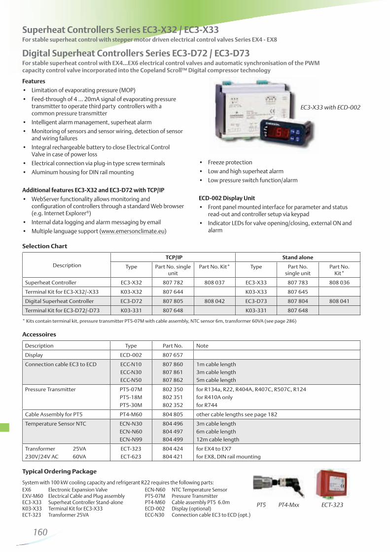
Superheat Controllers Series EC3-X32 / EC3-X33For stable superheat control with stepper motor driven electrical control valves Series EX4 - EX8
EC3-X33 with ECD-002
Typical Ordering Package
ECD-002 Display Unit
read-out and controller setup via keypad
alarm
ECT-323
Digital Superheat Controllers Series EC3-D72 / EC3-D73 For stable superheat control with EX4…EX6 electrical control valves and automatic synchronisation of the PWM capacity control valve incorporated into the Copeland Scroll™ Digital compressor technology
EXD-HP1/2 Stand-alone Superheat/Economizer Controller EXD-HP1/2 are stand-alone universal superheat and or economizer controllers for heat pumps, heating
units, air conditioning and precision cooling such as telecom and shelter applications.
EXD-HP2
Description TypePCN
M = Multipack (20 pieces) Singlepack
Controller with one EXV output EXD-HP1 807 836M -
Controller with two EXV outputs EXD-HP2 807 837M -
Temperature sensor with 3 meter cable ECP-P30 - 804 495
Pressure sensors (Suction pressure)-0.8…7 bar (R22, R134a, R407C) 0…..18 bar (R410A, R32)
Recommended for intermediate pressure (economizer control)See page 182
PT5-07M / PT5-07TPT5-18M / PT5-18T
PT6-18M
PT5-30M / PT5-30T
802 350M / 802 370M802 351M / 802 371M
802 361M
802 352M / 802 372M
802 350 / 802 370802 351 / 802 371
802 361
802 352 / 802 372
Plug and cable assembly for pressure sensor1.5m cable length3.0m cable length
PT4-M15PT4-M30
804 803M804 804M
804 803804 804
Selection Chart
Remark: For further details of EXM/EXL and PT5/PT6: Please see separate datasheet.
161
Simplified Illustration: Heating Scroll With Economizer
List of Alarms
Technical Data
Input Sensors, Output Valves
Alarm FunctionsEXD-HP1/2 provides several alarms to facilitate diagnosis as well as shut down of compressor/system if the alarm relay is wired into the serial safety loop.
Alarm Relay FunctionAlarm relay contains a SPDT contact. If the relay is wired to the system controller, it is possible to stop the compressor/system. The alarm relay is activated/energized during normal operation and deactivated/deenergized during alarm conditions as well as supply power interruption.
EXL
EXM
EXD-HP1/2
EvaporatorEconomizer
Condition Delay Time Alarm Relay Valve Position Reset Type Display Alarm LED
Hardware errors (sensors) - Triggered Fully close Auto ON
Hardware errors (Stepper motor) - Triggered - Auto ON
Low superheat Fix: 1 min. Triggered Fully close Auto/Manual ON/Blinking
Discharge hot gas above limit Fix: 1 min. Triggered Operating Auto ON
High superheat Adjustable Triggered Operating Auto ON
- Base board for superheat control or Economizer control- Alarm relay, dry contact. Relay coil is deenergized at alarm condition or power off and energized during normal operation- Hot gas discharge sensor input is mandatory only for economizer control function- Transformer shall be class 2
Remarks
- Upper board only for superheat control- Upper board does not need to be wired if circuit 2 of EXD-HP2 is disabled
163
Selection Chart
ECT-323
* Controller Kit contains terminal kit
Accessories
Description Type Part No. Note
Uninterruptible Power Supply ECP-024 804 558 for up to 2 driver modules
Electrical Terminal Kit K09-P00 804 560 for ECP-024
Transformer 25VA ECT-323 804 424
230V/24V AC 60VA ECT-623 804 421 DIN-rail mounting
Features
analogue input signal
analogue input and start mode
Options
automatically close valve after power down
Universal Driver Modules Series EXD-U00For the operation of ALCO® stepper motor valves EX4 / EX5 / EX6 / EX7 / EX8 as:
- Solenoid Valve
- Electrical Expansion Valve
- Hot Gas Bypass or Evaporating Pressure Regulator as capacity control
- Crankcase Pressure Regulator
- Heat Reclaim Regulator
- Liquid Level Control
EXD-U00
Description Type Part No. single unit Part No. Kit*
Universal Driver Module EXD-U00 804 557 808 038
Electrical Terminal Kit K09-U00 804 559
See electrical control valve EX4 ... EX8 data.
For function as:
Regulator see page 142
145
page 147
See datasheet A3.5.048 for detailed application drawings and technical data. For other than the specified operating conditions an Excel based Selection Tool can be downloaded from www.emersonclimate.eu
Capacity Data
ECP-024
164
Example for Web page monitoring
Features of EC2-3 models:
(e.g. EX2-Series) see Selection Table
Features of all models:
- via standard Web browser (EC2-xx2 models) - via LON communication (EC2-xx1 models) - with integral keypad
www.emersonclimate.eu)
Communication LON (see page 159)
for monitoring and configuration through a supervisory system
Display Case and Universal Controllers Series EC2With Web Server functionality and TCP/IP Protocol or with LON Protocol (FTT-10)
Communication TCP/IP Ethernet
a standard web browser. Ethernet interface, as used in most office PCs
Options
Standard screw terminal kit K02-000 available for all models.
OEM crimp versions available upon request
EC2 Controller
Selection Table
Functional Overview
TCP/IP LON
TypePart No.
single unitPart No.
Kit*Type
Part No. single unit
Part No. Kit*
Display Case and Cold Room Controllers
Temperature and Superheat Control of EX2 (Press. / Temp. input)Version for use with a compressor pack system
EC2-352EC2-372
807 772807 688
808 009808 011
EC2-351EC2-371
807 771807 689
808 008808 010
* Kit contains terminal kit, pressure transmitter PT5-07M with cable assembly, transformer 25VA, 4 NTC sensors 6m fin, pipe and air version (EC2-35x only)
Temperature and Superheat Control of EX2 (Temp. / Temp. input)Version for use with a compressor pack system
EC2-312EC2-392
807 682807 692
808 005808 007
EC2-311EC2-391
807 681807 691
808 004808 006
* Kit contains terminal kit, transformer 25VA, 5 NTC sensors 6m fin, pipe and air version (EC2-31x only), see also page 286.
Thermostat control, for Thermo-Expansion valve Version for use with a compressor pack system
EC2-212EC2-292
807 482807 672
808 001808 003
EC2-211EC2-291
807 481807 671
808 000808 002
* Kit contains terminal kit, transformer 25VA, 3 NTC sensors 6m fin, pipe (EC2-29x only) and air version (EC2-21x only), see also page 286.
Universal Controllerswith 2 digital inputs, 3 temperature inputs, 4 relay outputs
(including fin clip)6m cable length ECN-F60 804 283
Pressure transmitter-0.8…7 bar PT5-07M 802 350
0 ... 18 bar PT5-18M 802 351
Cable plug assembly for PT5
1.5m cable length PT4-M15 804 803
3m cable length PT4-M30 804 804
6m cable length PT4-M60 804 805
Transformer 230VAC Input, 24V output
25VA ECT-323 804 424
20VA ECT-523 804 332
Technical Data
Supply voltage 24V AC ±10% 50/60 Hz
class II only
Power consumption 20VA incl. EX2 valve (EC2-3xx)
4VA (EC2-11x, -21x, -29x)
Inputs up to 5 Temperature sensors:
Refrigerant inlet (saturated temp.)
Refrigerant outlet (suction temp.)
Air into / Air out of evaporator
Defrost termination
Output contact rating
cos ϕ = 0.5:
(Voltage free contacts)
SPDT & SPST relays,
250V max / 8A resistive load EC2-3xx
6A resistive load EC2-2xx
2A inductive load all EC2
(defrost, compressor, fan)
Triac output to EX2 24VAC, 1 A max.
Communication LON: FTT10 , TCP/IP: Ethernet
Temperature
storage
operation
operation
-10 … +70°C
0 … +50°C (housing)
- 50 … +50°C (NTC sensor)
Display 2 1/2 digits red LED
Automatic decimal point between
-19.9 & +19.9
Switchable between °C & °F
Indicator LEDs
Varies upon model
Compressor, defrost, fan, alarm,
service LED
Protection IP 65 (front protection with gasket)
Sensor type NTC 10KΩ @ 25°C
Order codes see above
Weight~ 150g
Typical Order Package for a display case
ECN-XX
166
Block Diagrams
EC2-31x / -39x Case Controller (EX2, Temp/Temp)
Inputs Outputs1 = Suction pressure 6 = EX2 Expansion valve2 = Coil out temperature 7 = Compressor (EC2-35x only)3 = Air in temperature Spare relay (EC2-37x only)4 = Air out temperature 8 = Fan 5 = Defrost temperature 9 = Defrost heater
Inputs Outputs1 = Coil in temperature 6 = EX2 Expansion valve2 = Coil out temperature 7 = Compressor (EC2-31x only)3 = Air in temperature Spare relay (EC2-39x only)4 = Air out temperature 8 = Fan5 = Defrost temperature 9 = Defrost heater
EC2-35x / -37x Case Controller (EX2, Press/Temp)
EC2-21x / -29x Case Controller (TXV) EC2-11x Universal I/O Controller
Inputs Outputs1 = Digital Input 6 = Solenoid valve2 = Digital Input 7 = Compressor (EC2-21x only)3 = Air in temperature Spare relay (EC2-29x only)4 = Air out temperature 8 = Fan5 = Defrost temperature
Inputs Outputs1 = Digital Input 6 = Digital output2 = Digital Input 7 = Digital output3 = Temperature input 8 = Digital output4 = Temperature input 9 = Digital output5 = Temperature input
Network
1
2
3
4
5
7
9
8
6
167
Features
Superheat control with self-adapting algorithm for Stepper Motor driven ECVs (EX4 ... EX8)
to close Control Valve in case of power loss
PT5 Series pressure transmitters
contact
programmable relay
- via TCP/IP Ethernet controller (EC3-332) - via LON communication (EC3-331) - with keypad of optional display unit ECD-001
terminals
mounting
(see www.emersonclimate.eu)
Communication TCP/IP Ethernet
detailed information on page 159
Communication LON
detailed information on page 159
Coldroom Controller Series EC3Temperature and Superheat Control of EX4 ...EX8 (Stepper Motor)
Features of ECD-001 Display Unit
Connection to EC3 Series via a RJ45 Western Digital plug. No further power cables required
Options
Front mounted ECD-001 Display Unit for temperature and output status indication
Typical Order Package Coldroom Controller EC3-332 807 632Terminal Kit K03-331 807 648Display Unit (optional) ECD-001 807 641Connection cable EC3 to ECD 1m ECC-N10 807 860Transformer 25VA ECT-323 804 424 Sensors: depending on application (see page 170)Ethernet Cable 5m ECC-N50 807 862
*Kit contains terminal kit, pressure transmitter PT5-07M with cable assembly, transformer 25VA, NTC sensors 6m fin, pipe and single insulated version (see also page 286)
Terminal Kits
Description Type Part No.
Terminal kit for EC3-33x K03-331 807 648
ECD Series Display Units
Display for EC3-33x ECD-001 807 641
Connection cable EC3 to ECD 1m (3m/5m see page 182) ECC-N10 807 860
Inputs Outputs1 = Coil out temperature 7= Compressor 2 = Air temperature 8= Defrost heater3 = Defrost temperature 9= Alarm4 = Suction pressure 10= Fan5 = Compressor safety 11= Stepper motor ECV6 = Door contact 12= Output signal (4...20 mA)
Network
EC3-33x Coldroom Controller for stepper motor driven ECV
170
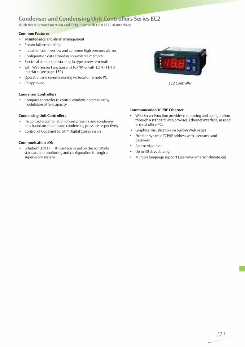
Condenser and Condensing Unit Controllers Series EC2With Web Server Function and TCP/IP or with LON FTT-10 Interface
Common Features
Interface (see page 159)
Condenser Controllers
modulation of fan capacity
Condensing Unit Controllers
fans based on suction and condensing pressure respectively
Communication LON® LON FTT10 interface based on the LonWorks
standard for monitoring and configuration through a supervisory system
Communication TCP/IP Ethernet
through a standard Web browser. Ethernet interface, as used in most office PCs
password
www.emersonclimate.eu)
EC2 Controller
171
Selection Table
Accessories
K02-211 ECT-323PT5 PT4-Mxx
TCP/IP LON
Description TypePart No.
single unitPart No.
Kit*Type
Part No. single unit
Part No. Kit*
Condensing Unit Controller for 2 compressors, 2 fans,
with on/off controlEC2-512 807 732 808 015
Condensing Unit Controller for 2 compressors or 1
Digital ScrollTM and 1 single stage compressor, variable
fan speed control with FSP module
EC2-552 807 738 808 019
* EC2-7xx Kits contain terminal kit, pressure transmitter PT5-30M with cable assembly, transformer 25VA (see also page 286).
Description Type Part No.
Terminal kits for EC2-51x, -71x series K02-211 807 647
Terminal kits for EC2-55x, -74x series K02-540 800 080
NTC Sensor, single insulated for ambient temp. sensing -50 … +50°C (10 kΩ at 25°C)
1.5m ECN-S15 804 304
3m ECN-S30 804 305
6m ECN-S60 804 284
NTC Sensor, single insulated for discharge, temps. sensing -50 … +150°C (1 MΩ at 25°C)
6m ECN-H60 804 359
Display unit for EC3-6xx to EC3-9xx ECD-000 807 640
Connection cable EC3 to ECD 1m (3m/5m see page 180) ECC-N10 807 860
175
EC3-672 Rack Controller for Capacity Controlled Compres-sors
Inputs1 = Suction pressure 2 = Discharge pressure 3 = Serial alarm inputs for up to 6 compressors4 = Low pressure alarm5 = High pressure alarm 6 = Oil level alarm7 = Refrigerant level alarm
Outputs8 = 12 outputs for up to 6x2 / 4x3 / 3x4 capacity controlled compressors
EC3-652 Rack Controller for 8 Single-Stage Compressors or 7 Single-Stage Compressors and 1 Digital ScrollTM
Inputs1 = Discharge temperatures of up to 8 compressors2 = Suction pressure 3 = Discharge pressure 4 = Serial alarm inputs for up to 8 compressors 5 = Low pressure alarm6 = High pressure alarm7 = Oil level alarm8 = Refrigerant level alarm
Outputs9 = for up to 8 compressors 10= to control a Digital ScrollTM
EC3-752 Condenser Controller
Inputs1 = Ambient temperature 2 = Humidity sensor3 = Condensing pressure4 = Serial alarm inputs for up to 6 fans 5 = High pressure alarm 6 = Heat recovery demand
Outputs 7 = For up to 6 stages, from which 1 can be speed controlled8 = Speed controlled fan (see 7)9 = Heat recovery solenoid
Block Diagrams
176
Inputs1 = Discharge temperature 2 = Ambient temperature 3 = Suction pressure 4 = Condensing pressure5 = Serial alarm inputs for 4 compressors 6 = Low pressure alarm 7 = High pressure alarm 8 = Oil level alarm9 = Refrigerant level alarm10 = Serial alarms for 3 fans11 = Heat recovery demand
Outputs 12 = Up to 4 compressors13 = Up to 3 fans, from with 1 fan can be speed controlled14 = Speed controlled fan (see 13)15= Heat recovery solenoid16= to control a Digital ScrollTM
Block DiagramsEC3-932 Rack and Condenser Controller (up to 4 compressors + condenser)
Inputs1 = Discharge temperature inputs of 3 compressors2 = Suction pressure group A 3 = Suction pressure group B4 = Serial alarm input for each compressor respectively5 = Refrigerant level alarm 6 = Low pressure alarm group A7 = Low pressure alarm group B8 = High pressure alarm9 = Oil level alarmOutputs 10 = For up to 4 compressors suction group A11 = For up to 3 compressors suction group B
177
Network Accessories
Examples for Use of Network Accessories
LON connected to Laptop ECC-034 interface. ECC-N10 RJ45 to RJ45 cable for connection between EC3 and ECD
ECD
ECC-N10
EC2EC3
ECC-034Echelon USB-FTT10 StickECC-034
Description Cable Length Type Part No.
Echelon USB-FTT10 interface stick (with USB cable) ECC-034 804 385
RJ45 to RJ45 Ethernet connection cable 1.5m ECC-N10 807 860
RJ45 to RJ45 Ethernet connection cable 3.0m ECC-N30 807 861
RJ45 to RJ45 Ethernet connection cable 5.0m ECC-N50 807 862
RJ45 to 4pin-connector cable for EC2 TCP/IP Contr. 6.0m ECX-N60 804 422
178
Selection Chart Kits*
Selection Chart Individual Components
EC3-D13 with ECD-002
EC3-D13 /EC3-D23 drivers receive an input signal from an existing system controller (0…10V, 1…6V or 4…20mA) and activate digital solenoid valves for stepless capacity control of the digital scroll and digital semi hermetic compressors .
For digital scroll compressors, an input allows monitoring of the discharge temperature or the compressor’s DLT signal and to activate an alarm signal if the specified temperature is exceeded.
Features
input signal
ECD-002 Display and key pad unit
Drivers for DIGITAL-Copeland™ Compressors EC3-D13/EC3-D23EC3-D13 driver for digital scroll compressors and 3 cylinder digital semi hermetic compressorsEC3-D23 driver for 4 and 6 cylinder Stream digital semi hermetic compressors
Description Type Copeland Part Number
Driver kit for digital scroll compressors EC3-D13 kit 8405187
Driver kit for 4 and 6 cylinder Stream digital semi hermetic compressors EC3-D23 kit 3187293
Description Type Copeland Part Number
Driver for digital scroll compressors EC3-D13 8404935
Driver for digital scroll compressors with terminal kit EC3-D13 & K03-331 3187306
Driver for 4 and 6 cylinder Stream digital semi hermetic compressors EC3-D23 3187282
Driver for 4 and 6 cylinder Stream digital semi hermetic compressors with terminal kit
EC3-D23 & K03-331 3187317
Display and key pad unit ECD-002 8403318
Terminal kit for Driver K03-331 8405165
Connection cable EC3-D13/23 to ECD-002, 1m ECC-N10 8557782
Transformer 230V AC input / 24 VAC, 25VA, DIN mount ECT-323 8405176
Kit contain EC3-D13/D23, ECD-002 keypad/Display unit, terminal kit K03-331, connection cable EC3 to ECD 13/23,
Connection to ECD-002 ECC-Nxx or CAT5 cable with RJ45 connectors
Digital Input I: 0/24VAC/DC for stop/start function
Analog Inputs O: 4…20mA, 0…10V, 1…6VN: Copeland NTC temperature sensor (86K at 25°C) or Discharge Line Thermostat (DLT)
Digital Outputs (2):
Activated:Deactivated:
H: AlarmL: Compressor relay for compressor contactorSPDT; Imax = 8A res (2A), VACmax = 250VDuring normal operation (no alarm condition)During alarm condition or power supply is OFF
Digital Scroll valve output SPST contact, Solid State Relay (SSR)Imax = 1A res (1A), VACmax = 250V
Ambient temperature range 0 ... 50°C
Wiring
180
The Compressor Soft Starter CSS-25U / CSS-32U is used for switching, protection and starting current limitation of single phase compressors in residential heat pump applications.
Features
calibration necessary
off after start
two directions
Compressor Soft Starter CSS-25U / CSS-32U
CSS-25U
Standards:
semiconductor motor controllers and starters
similar electrical appliances (PCN 805 204 and 805 205 only)
Wiring Diagram
CSS Contacts:R = Output motor run windingRC = Output run capacitorL = 230V / AC power inputN = Neutral lineUc = Start input (ON if connected to 230V)S = Output start winding from start capacitorA1, AC, A2 = Alarm relay contact
Technical Data
Operating voltage 230 V 50/60 Hz nominal
Compressor starting current limited to max. 45A
Operating temperature -20 ... +55°C non condensing
Storage temperature -20 ... +65°C non condensing
Start capacitor 200 ... 240 uF
Selection Chart CSS
Weight 430 g
Protection acc. IEC 529 IP 20
Max. vibration 4 g (at 10 … 1000 Hz)
Time delay after stop 0,5 to 5 min
Alarm relay, AgNi (SPDT) 250VAC / 3A
Type Part No. Part No. (20 pieces)
Description Imax
CSS-32U 805 204 805 204M Soft Starter incl. mounting clip and operating manual; VDE released version 32A max
CSS-25U 805 205 805 205M Soft Starter incl. mounting clip and operating manual; VDE released version 25A max
CSS-32U 805 200 805 200M Soft Starter incl. mounting clip and operating manual 32A max
CSS-25U 805 201 805 201M Soft Starter incl. mounting clip and operating manual 25A max
K00-003 807 663 - 3-pol Screw connector to alarm output for wires up to 2.5mm2; bag with 50 pieces
181
Pressure Transmitters convert a pressure into a linear electrical output signal. PT5 has been optimized for refrigeration applications.
Features
the precise operation of superheat, compressor or fan control systems
opener
requiring a fully hermetic system solution
assemblies available in various lengths
fulfill application demands in air conditioning and refrigeration systems
Standard pressure ranges compatible with former Emerson pressure transmitters - sealed gauge pressure
Options
Pressure Transmitter Series PT5
Standards:
PT5-xxT
PT5-xxM
Selection Chart Transmitters
Cable Assemblies
Type Part No. Output signalPressure range
(bar)
Max. allowable pressure PS
(bar)
Test pressure PT (bar)
Burst pressure (bar)
Pressure Connection
PT5-07M 802 350
4 ... 20 mA
-0.8 ... 7 27 30 1507/16” -20 UNF
(with schrader
valve opener)
PT5-18M 802 351 0 ... 18 55 63 250
PT5-30M 802 352 0 ... 30 60 100 400
PT5-50M 802 353 0 ... 50 100 150 400
PT5-07T 802 370
4 ... 20 mA
-0.8 ... 7 27 30 150
6mm tube x
60mm long
PT5-18T 802 371 0 ... 18 55 63 250
PT5-30T 802 372 0 ... 30 60 100 400
PT5-50T 802 373 0 ... 50 100 150 400
Type Part No. Temperature range (°C) Cable length (m) Leads
PT4-M15 804 803-50 ... +80 °C static application
-25 ... +80 °C mobile application
1.5
2 x 0,34 mm2PT4-M30 804 804 3.0
PT4-M60 804 805 6.0
PT4-Mxx
182
Supply Voltage Nominal 24 Vdc Sensor lifetime
Range (polarity protected) 7 ... 30 Vdc at full stroke at 25°C > 10.000.000 cycles
Operating current max. ≤ 24 mA output Burst pressure see selection chart
Protection class acc. to EN 60529 IP65 Medium compatibility HFC, HCFC, CFC
Medium -40 ... 100 °C diaphragm with medium contact 1.4534 / AISI 316L
Transportation and storage -25 ... 80 °C Vibration at 10 ... 2000 Hz 5g (IEC 68-2-6)
Pressure transmitters PT5 with current output (2-wire
connection) offer following advantages:
1. More suitable for signal transmission over long distances
2. Higher immunity to electromagnetic interference
Note: Changing the length of the electrical connection lead beyond 1.5 m
can have a negative impact on electromagnetic compatibility. Additional
protection may be required.
Electrical Connection
UB
- 7.0VR
L ≤
0.02A
*) Total error includes non-linearity, hysteresis, repeatability as well as offset and span drift due to the temperature changes.
Note: % FS is related to Percentage of Full sensor Scale.
BN = brown, supply voltage 24VWH = white, output signal 4 … 20mA(5) = Electronic Controller e.g. EC2 & EC3 Series
Technical Data
Accuracy Performance PT5
Temperature range Total error*
PT5-07M/T -40 ... +20°C ≤ ± 1 % FS
PT5-18M/T -40 ... +20°C ≤ ± 1 % FS
PT5-30M/T 0 ... +40°C ≤ ± 1 % FS
-20 ... +60°C ≤ ± 2 % FS
-40 ... +80°C typically ≤ ±2 % FS
PT5-50M/T 0 ... +40°C ≤ ± 1 % FS
-20 ... +60°C ≤ ± 2 % FS
-30 ... +80°C typically ≤ ±2 % FS
183
FSY-43S
Cable Assemblies with Plug and EMC Filter
FSF-N15
Selection Table
Features
peaks
molded into plug)
(opt. 3 and 6m) cable for flexible installation
per EC 89/336/EC (together with FSF cable)
Electronic Fan Speed Controller Series FSY
Type Part No.Operational
CurrentA
AdjustmentRange
bar
FactorySetting
bar
Max. Operating Pressure PS
bar
TestPressure PT
barPressure Connection
FSY-41S 0 715 533
0.1 ... 4
4.0 ... 12.5 8.0 27 30 S: 7/16”-20 UNF female
FSY-42S 0 715 534
9.2 ... 21.2 15.0 32 36
S: 7/16”-20 UNF female
FSY-42U 0 715 535 U: 6mm - ODF
FSY-42X 0 715 536 X: 1/4“ - ODF
FSY-43S 0 715 537
12.4 ... 28.4 21.8 45 50
S: 7/16”-20 UNF female
FSY-43U 0 715 538 U: 6mm - ODF
FSY-43X 0 715 539 X: 1/4“ - ODF
Type Part No. Temperature range (°C) Cable length (m)
FSF-N15 804 640
-50 .. +80
1.5
FSF-N30 804 641 3.0
FSF-N60 804 642 6.0
184
Supply voltage 230 AC, +15%, -20%, 50/60 Hz
Nominal current
(see diagram below)
0.1 ... 4 (3) A
Starting current max. 8 Ampère/5 sec.
Medium compatibility HFC, HCFC
(not released for use with
inflammable refrigerants)
Protection Class according to
IEC529 /DIN 40050
IP 65 (with fitted connectors
FSF-xxx)
Temperature ranges ambient
storage, transportation medium
-20 to +55 °C
>40°C see diagramm
-30 to +70°C
-20 to +70°C
Max. Current vs Ambient Temperature
Technical Data
Function Diagram
The control behaviour can be easily described by looking at the function of output voltage versus input pressure: In the maximum range the FSY provides a constant output voltage of approximately 1% below the supply voltage. The fan is running at maximum speed. Along the proportional range, the output voltage varies between maximum and minimum voltage of approximately 50% of the supply voltage. This causes the fan to slow down from maximum to minimum speed.
Further decrease of pressure in the minimum range leads to cut-off of the fan motor. Reincrease of input pressure will start the motor with a hysteresis of approximately 0.7 bar to avoid cycling. The pressure from which motor cuts off is adjustable (see selection table - adjustment range).
Pressure change per turn of
adjustment screw
FSY-41: 4,0 .. 12.5 bar
clockwise ~ +1.2 bar
counter clockwise ~ –1.2 bar
FSY-42: 9,2 .. 21.2 bar
clockwise ~ +2.5 bar
counter clockwise ~ –2.5 bar
FSY-43: 12,4 .. 28.4 bar
clockwise ~ +3.3 bar
counter clockwise ~ –3.3 bar
Proportional Range FSY-41: 2.5 bar
FSY-42: 3.8 bar
FSY-43: 4.6 bar
Weight
FSY-41, -42
FSY-43
FSF-N15
FSF-N30
FSF-N60
approx.
0.12 kg
0.15 kg
0.14 kg
0.20 kg
0.22 kg
Housing material PC and PA
01234
30 35 40 45 50 55
Curr
ent(A
)
Ambient Temperature (°C)
185
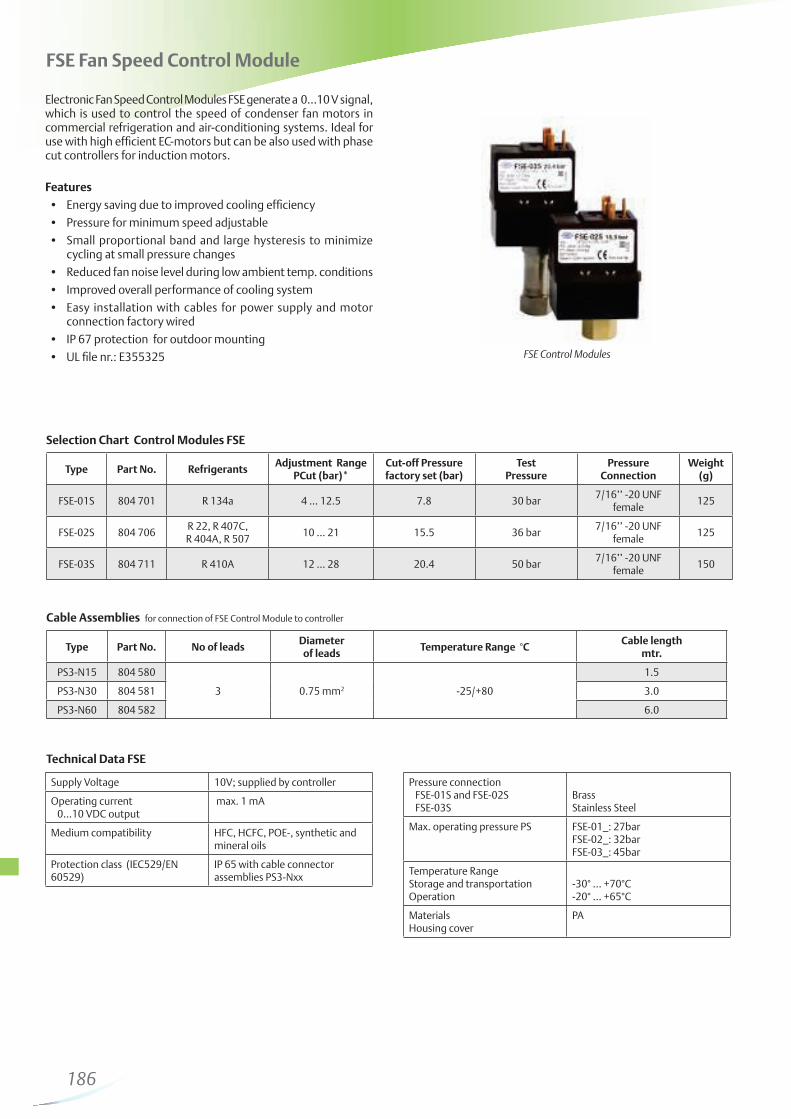
FSE Fan Speed Control Module
Electronic Fan Speed Control Modules FSE generate a 0…10 V signal, which is used to control the speed of condenser fan motors in commercial refrigeration and air-conditioning systems. Ideal for use with high efficient EC-motors but can be also used with phase cut controllers for induction motors.
Features
cycling at small pressure changes
connection factory wired
FSE Control Modules
Selection Chart Control Modules FSE
Technical Data FSE
Cable Assemblies for connection of FSE Control Module to controller
Temperature RangeStorage and transportationOperation
-30° … +70°C-20° … +65°C
MaterialsHousing cover
PA
186
Thermo™-Expansion Valves
187
188
Thermo™ Expansion Valves
Basic Terms and Technical Information
Operating principlesAlco Thermo-Expansion valves control the superheat of refrigerant vapour at the outlet of the evaporator. They act as a throttle device between the high pressure and the low pressure sides of refrig-eration systems and ensure that the rate of refrigerant flow into the evaporator exactly matches the rate of evaporation of liquid refrigerant in the evaporator. Thus the evaporator is fully utilized and no liquid refrigerant may reach the compressor.
Description of bulb chargesThe application ranges of Thermo-Expansion valves are heavily influenced by the charge selected.
Liquid chargesThe behaviour of Thermo-Expansion valves with liquid charges is exclusively determined by temperature changes at the bulb and not subject to any cross-ambient interference. They feature a fast response time and thus react quickly in the control circuit. Liquid charges cannot incorporate MOP functions. Maximum bulb temperatures shall not exceed 75°C.
Gas chargesThe behaviour of Thermo-Expansion valves with gas charges will be determined by the lowest temperature at any part of the expansion valve (power assembly, capillary tube or bulb). If any parts other than the bulb are subject to the lowest temperature, malfunction of the expansion valve may occur (i.e., erratic low pressure or excessive superheat). Alco Thermo-Expansion valves with gas charges always feature MOP functions and include ballasted bulbs. Ballast in the bulb leads to slow opening and fast closure of the valve. Maximum bulb temperature is 120°C.
Adsorption chargesThese charges feature control characteristics much like MOP charges but avoid the difficulties of cross-ambient interference. Response time is slow but perfectly suitable for common refriger -ation systems. Maximum bulb temperature is 130°C.
MOP (Maximum Operating Pressure)MOP functionality is somewhat similar to the application of a crankcase pressure regulator. Evaporator pressures are limited to a maximum value to protect compressor from overload conditions.MOP selection should be within maximum allowed low pressure rating of the compressor and should be at approximately 3K above evaporating temperatures.
Practical hint: Superheat adjustments influence the MOP: Increase of superheat: Decrease of MOP Decrease of superheat: Increase of MOP
Static superheatAlco Thermo-Expansion valves are factory preset for optimum su-perheat settings. This setting should be modified only if abso lutely necessary. The readjustment should be at the lowest expected evaporating temperature.
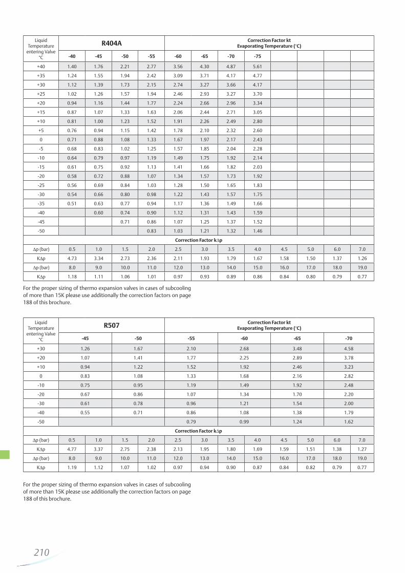
SubcoolingSubcooling generally increases the capacity of the refrigeration system and may be accounted for when dimensioning an expansion valve by applying the correction factor K
t. The capacity
corrections for evaporating temperature, condensing temperature and subcooling are all incorporated in K
t. These are, in particular
the liquid density upstream from the expansion valve, the different enthalpies of liquid and vapour phase refrigerants, as well as certain parts of flash gas after expansion. The percentage of flash gas differs with various refrigerants and depends on system conditions.
Heavy subcooling results in very small flash gas amounts and therefore increases expansion valve capacities. These conditions are not covered by K
t. Likewise, small flash gas amounts lead
to reduced evaporator capacities and may result in substantial discrepancies between the capacities of the Thermo-expansion valve and the evaporator. These effects must be considered during component selection when designing refrigeration circuits. In cases when subcooling exceeds 15 K, sizing of components (K
t,
K∆p) should be modified accordingly. The field practice indicates the following correction factors can be used to compensate the effect of the subcooling (liquid hammering) in addition to the use of correction factors K
t, and K∆p.
Emerson Climate Technologies will be happy to assist you. Please contact the application engineering department.
DimensioningTo correctly select a Thermo-Expansion valve on a system, the following design conditions must be available:- Cooling capacity Q
O
- Effective pressure differential across Thermo-Expansion valve ∆p
- Evaporating temperature/pressure- Lowest possible condensing temperature/pressure- Liquid temperature- Type of refrigerant
As opposed to single substances (e.g. R134a etc.) where the phase change takes place at a constant temperature/pres sure, the evaporation and condensation of zeotropic blend R407C is in a gliding form (e.g., at a constant pressure the temperature varies within a certain range) through evaporators and condens-ers. The evaporating/condensing pressure must be determined at saturated temperatures (bubble/dew points) for dimensioning of Thermo®-Expansion valves.
To facilitate valve dimensioning for other than standard conditions, Emerson Climate Technologies offers a Selection Tool. This can be ordered from all Emerson sales offices.See www.emersonclimate.eu for contact addresses, email, phone numbers or download.
Subcooling 20K 30K 40K 50K 60K
Correction factor 0.8 0.7 0.6 0.5 0.4
189
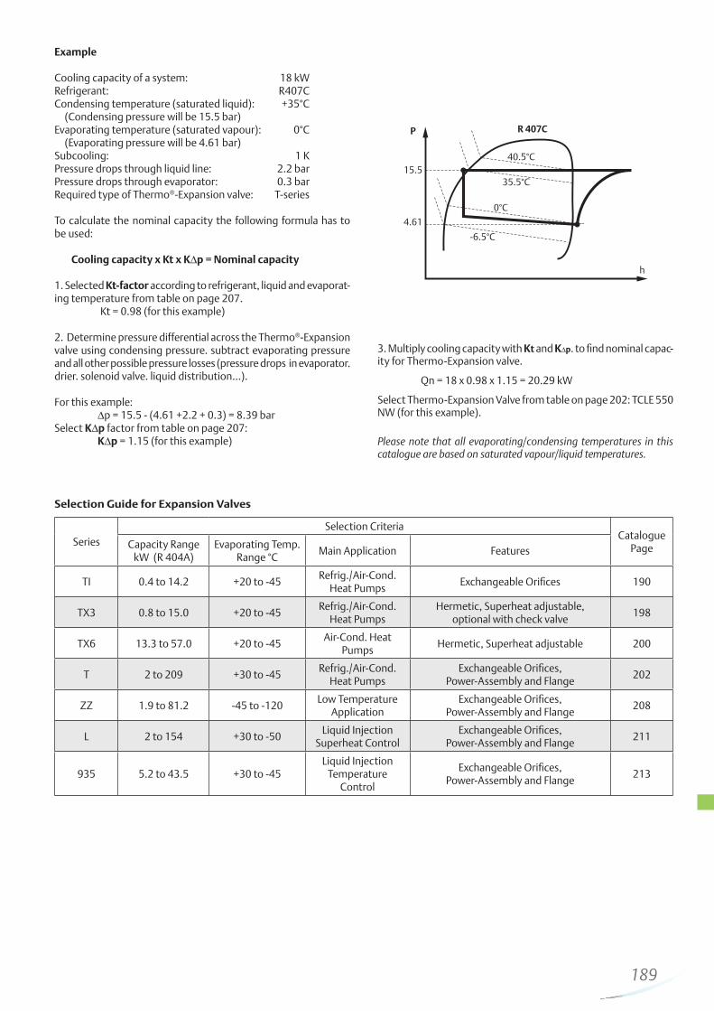
Example
Cooling capacity of a system: 18 kWRefrigerant: R407CCondensing temperature (saturated liquid): +35°C (Condensing pressure will be 15.5 bar) Evaporating temperature (saturated vapour): 0°C (Evaporating pressure will be 4.61 bar)Subcooling: 1 KPressure drops through liquid line: 2.2 barPressure drops through evaporator: 0.3 barRequired type of Thermo®-Expansion valve: T-series
To calculate the nominal capacity the following formula has to be used:
Cooling capacity x Kt x K∆p = Nominal capacity
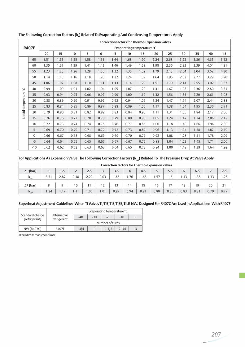
1. Selected Kt-factor according to refrigerant, liquid and evaporat-ing temperature from table on page 207. Kt = 0.98 (for this example)
2. Determine pressure differential across the Thermo®-Expansion valve using condensing pressure. subtract evaporating pressure and all other possible pressure losses (pressure drops in evaporator. drier. solenoid valve. liquid distribution…).
For this example: ∆p = 15.5 - (4.61 +2.2 + 0.3) = 8.39 barSelect K∆p factor from table on page 207: K∆p = 1.15 (for this example)
3. Multiply cooling capacity with Kt and K∆p. to find nominal capac-ity for Thermo-Expansion valve.
Qn = 18 x 0.98 x 1.15 = 20.29 kW
Select Thermo-Expansion Valve from table on page 202: TCLE 550 NW (for this example).
Please note that all evaporating/condensing temperatures in this catalogue are based on saturated vapour/liquid temperatures.
P
15.5
4.61
h
R 407C
40.5°C
35.5°C
0°C
-6.5°C
Selection Guide for Expansion Valves
Series
Selection CriteriaCatalogue
PageCapacity RangekW (R 404A)
Evaporating Temp. Range °C
Main Application Features
TI 0.4 to 14.2 +20 to -45Refrig./Air-Cond.
Heat PumpsExchangeable Orifices 190
TX3 0.8 to 15.0 +20 to -45Refrig./Air-Cond.
Heat PumpsHermetic, Superheat adjustable,
optional with check valve198
TX6 13.3 to 57.0 +20 to -45Air-Cond. Heat
PumpsHermetic, Superheat adjustable 200
T 2 to 209 +30 to -45Refrig./Air-Cond.
Heat PumpsExchangeable Orifices,
Power-Assembly and Flange202
ZZ 1.9 to 81.2 -45 to -120Low Temperature
ApplicationExchangeable Orifices,
Power-Assembly and Flange208
L 2 to 154 +30 to -50Liquid Injection
Superheat ControlExchangeable Orifices,
Power-Assembly and Flange211
935 5.2 to 43.5 +30 to -45Liquid Injection
Temperature Control
Exchangeable Orifices,Power-Assembly and Flange
213
190
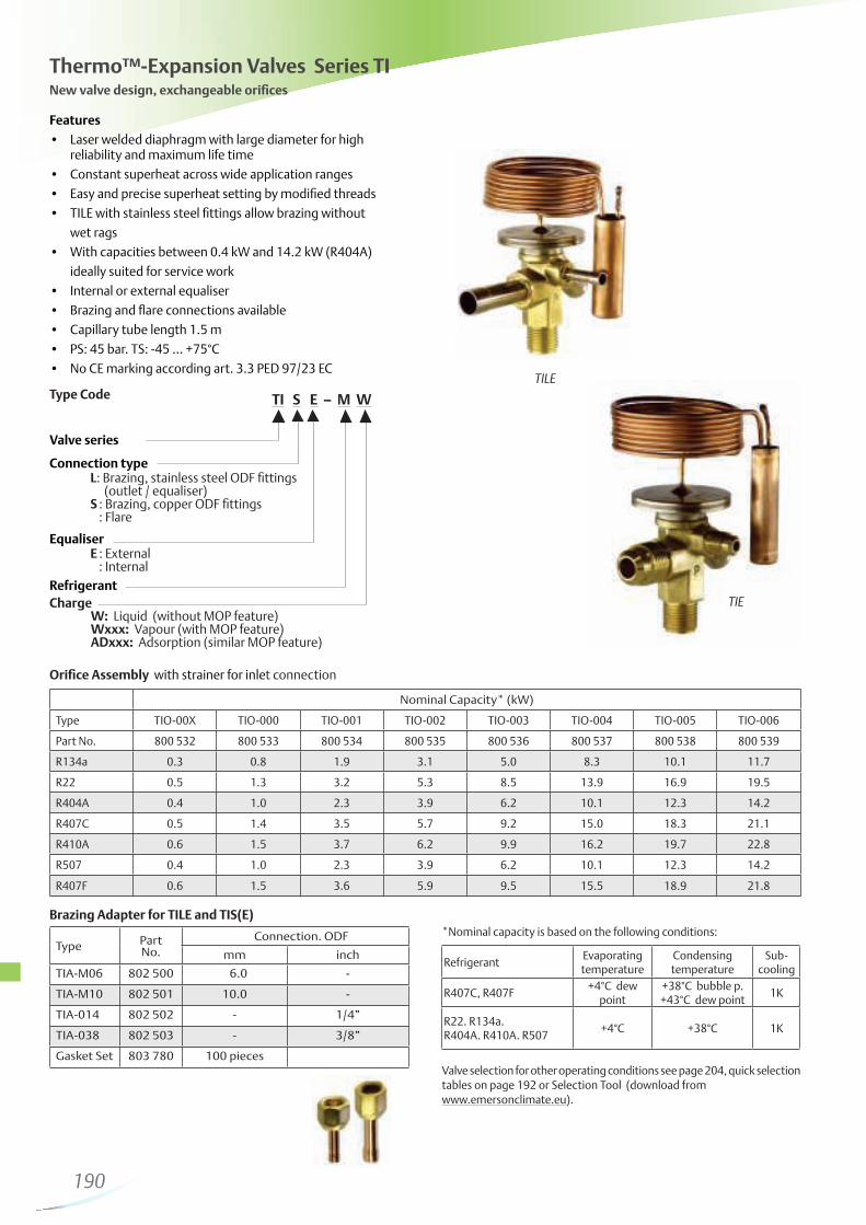
TILE
Thermo™-Expansion Valves Series TINew valve design, exchangeable orifices
Type Code TI S E – M W
Valve series
Connection type L: Brazing, stainless steel ODF fittings (outlet / equaliser) S : Brazing, copper ODF fittings : Flare
Orifice Assembly with strainer for inlet connection
Valve selection for other operating conditions see page 204, quick selection tables on page 192 or Selection Tool (download from www.emersonclimate.eu).
*Nominal capacity is based on the following conditions:
RefrigerantEvaporating temperature
Condensingtemperature
Sub- cooling
R407C, R407F+4°C dew
point+38°C bubble p.+43°C dew point
1K
R22. R134a. R404A. R410A. R507
+4°C +38°C 1K
Brazing Adapter for TILE and TIS(E)
Type PartNo.
Connection. ODF
mm inch
TIA-M06 802 500 6.0 -
TIA-M10 802 501 10.0 -
TIA-014 802 502 - 1/4”
TIA-038 802 503 - 3/8”
Gasket Set 803 780 100 pieces
Nominal Capacity* (kW)
Type TIO-00X TIO-000 TIO-001 TIO-002 TIO-003 TIO-004 TIO-005 TIO-006
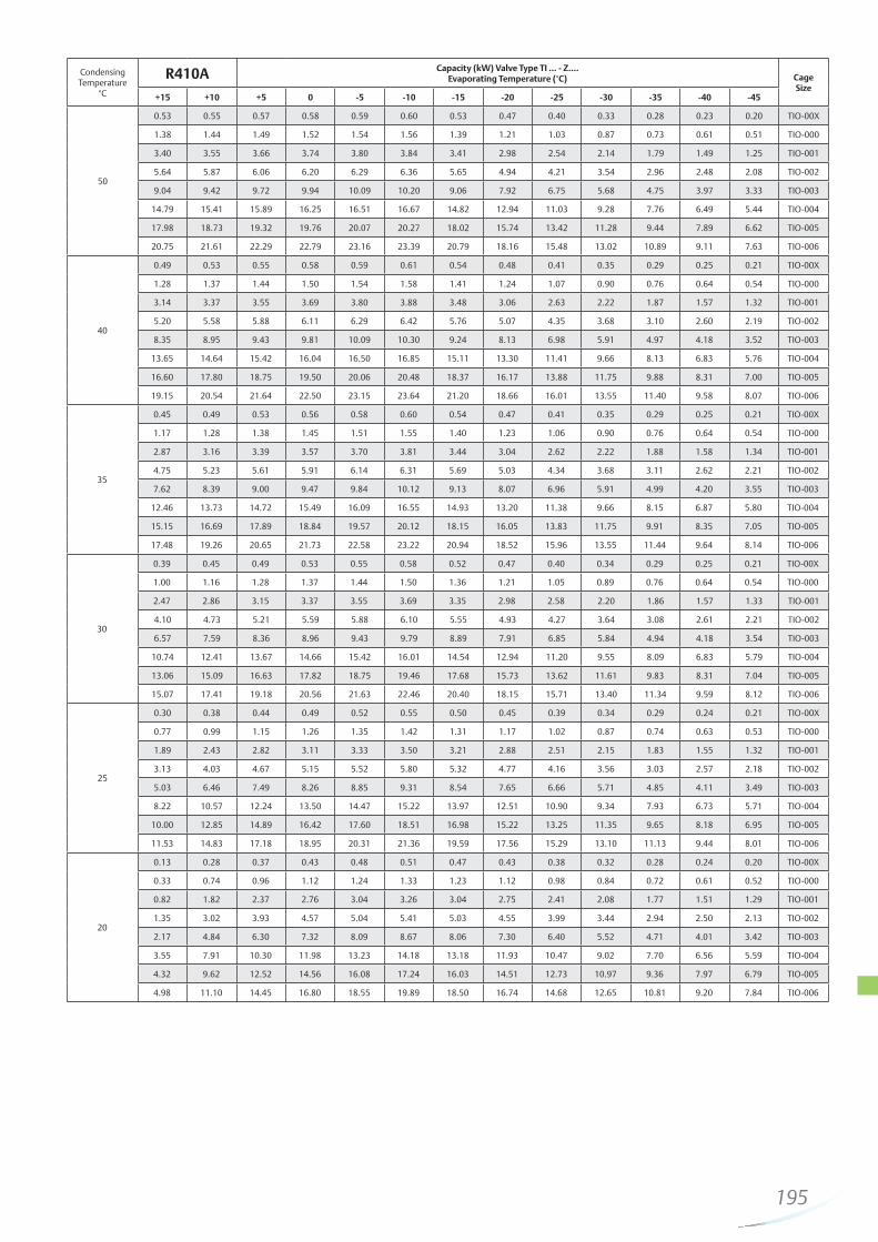
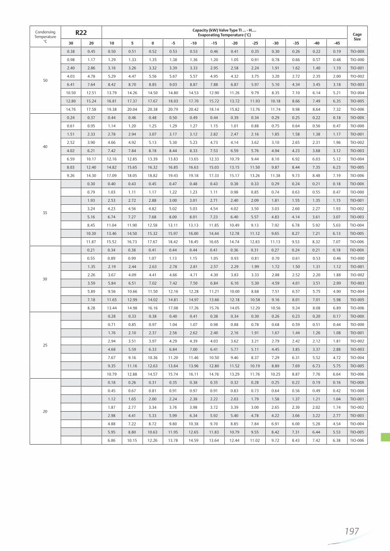
Published capacity data at 1 K subcooling at the inlet of the expansion valve and 1.5 bar pressure drop in the refrigeration system. For proper valve selection especially in case of high pressure drops, we recommend the use of correction factors (see page 204).
To facilitate valve dimensioning for other than the standard condi-tions, Emerson Climate Technologies offers a Selection Tool (www.emersonclimate.eu).
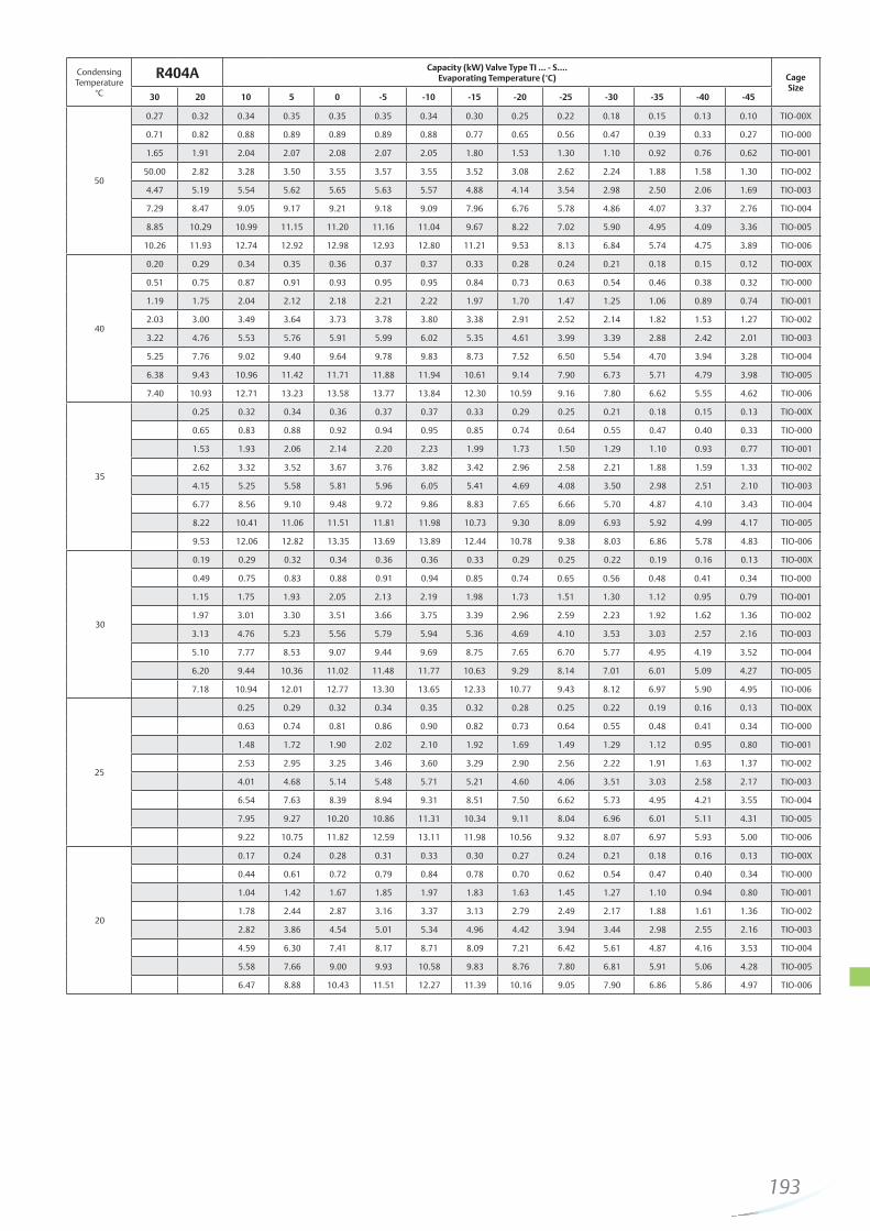
Condensing Temperature
°C
R134a Capacity (kW) Valve Type TI … - M….Evaporating Temperature (°C) Cage
For the proper sizing of thermo expansion valves in cases of subcooling of more than 15K please use additionally the correction factors on page 188 of this brochure.
For the proper sizing of thermo expansion valves in cases of subcooling of more than 15K please use additionally the correction factors on page 188 of this brochure.
Liquid Temperature
entering Valve °C
R404A Correction Factor ktEvaporating Temperature (°C)
Power AssemblyCharge CodeCapillary Tube Length (3 m)External Equalization
Series
Nominal Capacity Qn
kWOrifice
ConnectionsStandard Flange. Angle
Solder/ODFPower
Assembly
R134a R22 R404A R407C R507 mm inch
LCLE
1 * 1.5 1.9 1.3 2.1 1.3 X 22440-B1B
C 501 – 5 mm10 x16
XB1019…2B
2 * 2.9 3.7 2.6 4.0 2.6 X 22440-B2B
3 * 6.1 7.9 5.6 8.5 5.6 X 22440-B3B
3.5 * 9.3 11.9 8.4 12.9 8.4 X 22440-B3.5B
4 * 13.5 17.3 12.2 18.7 12.2 X 22440-B4B
6 * 17.3 22.2 15.7 24.0 15.7 X 22440-B5B C 501 – 7 mm12 x 167 * 23.6 30.4 21.5 32.9 21.5 X 22440-B6B
9 * 32.0 41.1 29.0 44.4 29.0 X 22440-B7B A 576 mm16 x 22
(22 x 28 ODM)
A 576 5/8 x 7/8
(7/8 x 1 1/8 ODM)10 * 37.2 47.8 33.8 51.7 33.8 X 22440-B8B
LJRE
11 * 45 58 40 62 40 X 11873-B4B
1033122 x 22
103317/8 x 7/8
(1 1/8 x 1 1/8 ODM)12 * 57 74 51 80 51 X 11873-B5B
LERE
13 * 71 91 63 99 63 X 9117-B6B
9153 mm22 x 22
91537/8 x 7/8
(1 1/8 x 1 1/8 ODM)XC726…2B
14 * 81 104 72 112 72 X 9117-B7B
15 * 112 143 99 155 99 X 9117-B8B
16 * 135 174 120 188 120 X 9117-B9B
LIRE 17 * 174 223 154 241 154 X 9166-B10B
* Charge Code
Refrigerant
R134a R22 R404A R407C R507
CL - 15 K 22 K 13 K 22 K
GL 15 K 30 K 35 K 25 K 35 K
UL 30 K 45 K 40 K
Nominal capacity (Qn) is based on the following conditions:
RefrigerantEvaporating temperature
Condensing temperature
Sub-cooling
R407C+4°C dewpoint
+38°C bubble point+43°C dew point
1K
R22, R134a, R404A, R507 +4°C +38°C 1K
Valve selection for other operating conditions see page 204* Please indicate designation character for desired superheat
211
Valve selection for desuperheating of suction gas:
The required desuperheating capacity Qdes
has to be multiplied with the correction factors on page 204.
Qdes
x Kt x K∆p = Q
n
Qdes
: Required desuperheating capacityK
t : Correction factor for evaporating and
liquid temperatureK∆p : Correction factor for pressure drop at valveQ
n : Nominal valve capacity
Available upon special request
pressure equalization
Valve selection for desuperheating of suction gas in conjunc-tion with hotgas-bypass regulation:
The required bypass capacity QByp
has to be multiplied with cor-rection factor K
ti per table below.
QByp
x Kti = Q
n
QByp
: Required bypass capacityK
ti : Correction factor for evaporating
temperatureQ
n : Nominal valve capacity
Correction factors based on 20K superheat suction gas at the inlet of compressor, discharge temperature 28K above isentropic compression and 1K subcooling.
Correction Tables for Series L
Spare Parts
Type Part No.
Gasket Set for L Series Valves X 13455 -1 027 579
Service Tool for L Series X 99999 800 005
Steel screws for following flange types:C501, 9761, 6346, A5769148, 9149, 9152, 9153, 10331, 10332
C 501 - 5 803 232 9761 - 3 803 240 - - 3/8 x 5/8 - TCLE
C 501 - 5 MM 803 233 9761 - 3 MM 803 241 10 x 16 - - - ZZCE
C 501 - 7 803 234 9761 - 4 803 350 - - 1/2 x 5/8 - LCLE
C 501 - 7 MM 803 235 9761 - 4 MM 803 243 12 x 16 - - - 935 A-X
- - 6346 - 17 803 330 16 x 22 - 5/8 x 7/8 - CPHE 1
A 576 803 238 - - - - 5/8 x 7/8 7/8 x 1-1/8 CPHE 2
A 576 - MM 803 239 - - 16 x 22 22 x 28 - -
10331 803 338 10332 803 324 22 x 22 - 7/8 x 7/8 1-1/8 x 1-1/8TJRELJRE
CPHE 3
91539153 MM
803 244803 245
91529152 MM
803 286803 287
-22 x 22
-28 x 28
7/8 x 7/8-
1-1/8 x 1-1/8
TERETIRELERELIRE
CPHE 3.5CPHE 4CPHE 5
9149 803 284 9148 803 283 22 x 22 - 7/8 x 7/8 1-1/8 x 1-1/8THRE
CPHE 6
217
218
Solenoid Valves
219
2-Way-Solenoid ValvesBasic Terms and Technical Information
Operating principles
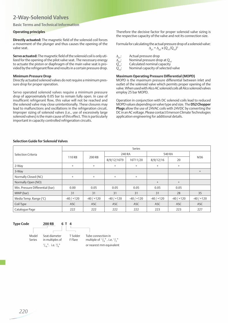
Directly actuated: The magnetic field of the solenoid coil forces a movement of the plunger and thus causes the opening of the valve seat.
Servo actuated: The magnetic field of the solenoid coil is only uti-lized for the opening of the pilot valve seat. The necessary energy to actuate the piston or diaphragm of the main valve seat is pro-vided by the refrigerant flow and results in a certain pressure drop.
Minimum Pressure DropDirectly actuated solenoid valves do not require a minimum pres-sure drop for proper operation.
Servo operated solenoid valves require a minimum pressure drop of approximately 0.05 bar to remain fully open. In case of insufficent refrigerant flow, this value will not be reached and the solenoid valve may close unintentionally. These closures may lead to malfunctions and oscillations in the refrigeration circuit. Improper sizing of solenoid valves (i.e., use of excessively large solenoid valves) is the main cause of this effect. This is particularly important in capacity controlled refrigeration circuits.
Therefore the decisive factor for proper solenoid valve sizing is the respective capacity of the valve and not its connection size.
Formula for calculating the actual pressure drop of a solenoid valve:∆
p1 = ∆
p2 x (Q
n1/Q
n2)2
∆p1
: Actual pressure drop∆
p2: Nominal pressure drop at Q
n1
Qn1
: Calculated nominal capacityQ
n2: Nominal capacity of selected valve
Maximum Operating Pressure Differential (MOPD)MOPD is the maximum pressure differential between inlet and outlet of the solenoid valve which permits proper opening of the valve. When used with Alco AC solenoid coils all Alco solenoid valves employ 25 bar MOPD.
Operation in conjunction with DC solenoid coils lead to reduced MOPD values depending on valve type and size. The DS2 Chopper Plugs allow the use of 24VAC coils with 24VDC by converting the DC in an AC voltage. Please contact Emerson Climate Technologies application engineering for additional details.
Type Code 200 RB 6 T 4
Model Seat diameter T Solder Tube connection in Series in multiples of F Flare multiple of 1/
8” . i.e. 1/
2”
1/16
”. i.e. 3/8” or nearest mm equivalent
Selection Guide for Solenoid Valves
Selection Criteria
Series
110 RB 200 RB240 RA 540 RA
M368/9/12/16T9 16T11/20 8/9/12/16 20
2-Way + + + + + +
3-Way +
Normally Closed (NC) + + + +
Normally Open (NO) + +
Min. Pressure Differential (bar) 0.00 0.05 0.05 0.05 0.05 0.05
Type Part No. Voltage Power Input Electr. Connection Protection
ASC 230V / 50Hz 801 064 8 W without plug. see cable as-semblies
IP65with plug / cable assembly
ASC 120V / 50Hz 801 063
ASC 24V / 50Hz 801 062
ASC 24V DC 801 974 DC 15 W
DS2-N15 + ASC 24VAC 804 620 + 801 062 DC 3 W with plug and cable assembly IP65
Note: Coils are delivered with mounting clip. Please order cable assemblies separately.
Type Part No. Temperature Range Cable length Wire diameter Connector Type
ASC-N15 804 570-50 .. +80°C
for stationary use only
1.5m
3 x 0.75 mm2 loose wiresASC-N30 804 571 3.0m
ASC-N60 804 572 6.0m
Type Part No. Temperature Range Cable length Wire diameter Connector Type
DS2-N15 804 620 -25 .. +80°C 1.5 m 2 x 0.75 mm2 loose wires
Type Part No. Description
X 11981-1 027 451 Service tool for 110RB. 240RA. 540RA. 3031
X 13740 -1 027 600 Clip for coil
PG9 Plug 801 012 Plug according to DIN 43650 with cable gland PG 9
PG11 Plug 801 013 Plug according to DIN 43650 with cable gland PG 11
221
240 RA
200 RB
110 RB
2-Way Solenoid Valves Series 110, 200, 240 Normally Closed
Nominal capacities at +38°C condensing temperature. +4°C evaporating temperature. 0.15 bar pressure drop between valve inlet and outlet in liquid applications (for hot gas applications 1 bar pressure drop and +18 °C suction gas temperature); subcooling 1 K. Correction tables for other operating conditions see page 227
Nominal capacities at +38°C condensing temperature. +4°C evaporating temperature. 0.15 bar pressure drop between valve inlet and outlet in liquid applications (for hot gas
applications 1 bar pressure drop and +18 °C suction gas temperature); subcooling 1 K. Correction tables for other operating conditions see page 227.
For Liquid Line Applications The Following Correction Factors (kt) Related To Evaporating And Condensing Temperatures Apply
For Liquid Line Applications The Following Correction Factors (k∆p) Related To The Pressure Drop At Valve Apply
R407F
226
227
M36-118 M36-078 with ASC Coil
and DS2 Chopper Plug
Features
pressure drop
Options:
various voltages, see page 221
Nominal capacities at +38°C condensing temperature. +4°C evaporating temperature (saturated pressures / dew point). 0.15 bar pressure drop between valve inlet and outlet.
For other operating conditions multiply required capacity Qo with
correction factors Kt and K∆p.
Qo x K
t x K∆p = Q
n
3-Way Solenoid Valves Series M36
Capacity Data
Correction Tables
Qo: Required cooling capacity
Kt: Correction factor for evaporating and liquid
temperatureK∆p: Correction factor for pressure drop at valveQ
n: Nominal valve capacity
Accessories and spare parts for series M36
Type Part No.Connection Solder/ODF Nominal Capacity Q
Conversion Table 3031 Series to M363031 Series has been replaced by M36 Series
former type Part No. Replacement Part No.
3031 RC 12S7 055 939 M36-078 801 420
3031 RC 12S9 055 940 M36-118 801 421
228
Mechanical Pressure Regulators
229
230
Selection Guide for Pressure Regulators
Basic Terms and Technical Information
Capacity RegulatorsRegulator series ACP and CPHE are hot gas bypass regulators and serve the purpose of compensating excess compressor capacity. Thus they prevent the generation of evaporator pressures below predetermined levels.
In case of hot gas injection into the suction line, a liquid injection valve in conjunction with a solenoid valve is required to desuperheat the excessively hot suction gas. The capacity should not be reduced below 60% of maximum in this application to avoid oil return problems.
With hot gas injection at the evaporator inlet, no liquid injection valve is necessary. The injection must be such that the incre-
return should be expected even when regulating 100% of capacity.
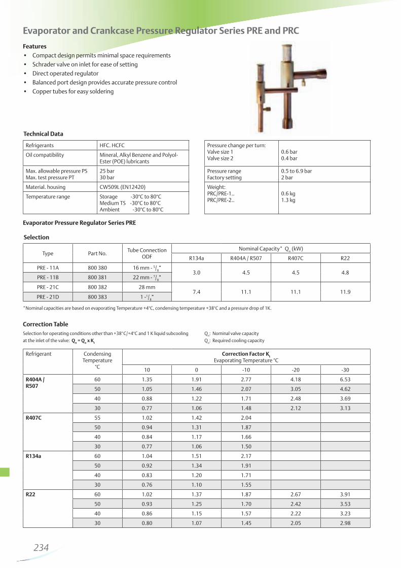
Evaporator Pressure RegulatorsSeries PRE regulators serve the purpose of maintaining evaporator pressure above certain predetermined levels. The most important application is the use of several evaporators with different evaporating temperatures in conjunction with a common suction line.
The freezing of water in water chillers and air conditioning systems
0°C, even when loads are greatly reduced.
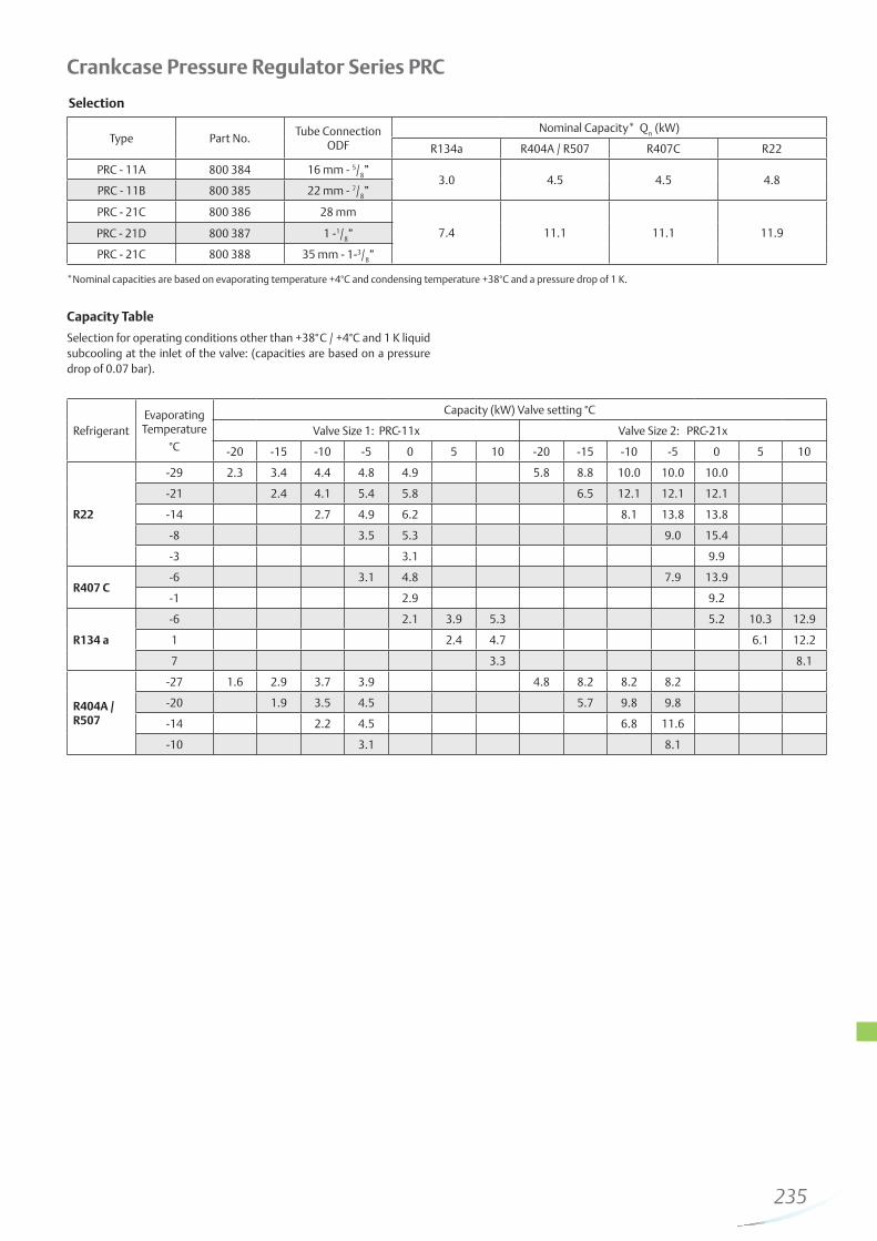
Crankcase Pressure RegulatorsSeries PRC regulators serve the purpose of preventing exces-sively high suction pressures to protect compressor motors from overloading.
Excessively high suction pressures can occur at start-up of a refrigeration circuit in case of high loads and after defrost.
suction pressure rating of the compressors as given by the compressor manufacturers.
Selection CriteriaSeries
ACP CPHE PRE PRC
Capacity Regulator + +
Evaporator Pressure Regulator +
+
Catalogue Page 231 232 234 235
231
Features
High quality materials and processes for high reliability and long lifetime
Internal equalization
Compact size
Hot Gas Bypass Regulators Series ACP
* Nominal capacities at +38°C condensing temperature. +4°C evaporating temperature (saturated temperatures / dew point) and 1 K liquid sub cooling at the inlet of the expansion valve.
Technical Data
Capacity Data
Adjustment Range 0 ... 5 bar
Factory Setting 2.7 bar
Max. allowable Pressure PS 31 bar
Medium Temperature Range TS –40°C ... 120°C
Ambient Temperature Range -40 ... 50°C
Transport Temperature Range -40 ... 70°C
Type Part No.Connection. Angle
Solder/ODFinch
Nominal Bypass Capacity* Qn
R134a R22 R407C R404A / R507
ACP 1 047 680 1/4 x 3/
8” 0.21 0.35 0.41 0.30
ACP 3 047 283 1/4 x 3/
8” 0.50 0.77 0.89 0.68
ACP 5 053 374 3/8 x 3/
8” 1.18 1.83 2.12 1.59
ACP
232
Nominal capacities at +38°C condensing temperature, +4°C evaporating temperature (saturated temperatures / dew point) and 1 K liquid sub cooling at the inlet of the expansion valve.
Capacity Data CPHE
Specific connection sizes and flanges available on request. For selection, see page 217.
CPHE
Features
High quality materials and processes for high reliability and long lifetime
Superior partial load performance due to double seat orifice design (CPHE3 to CPHE6)
Modular design for economical logistics and easy assembly and servicing
External equalization
Specific connection sizes and flanges available on request.For selection see page 217
Hot Gas Bypass Regulators Series CPHE
Technical Data
Adjustment Range -0.4 ... 5 bar
Factory Setting 1.4 bar
Max. allowable Pressure PS 35 bar
Medium Temperature Range TS –40°C ... 120°C
Ambient Temperature Range -40 ... 50°C
Transport Temperature Range -40 ... 70°C
Type Nominal Bypass Capacity Qn Orifice Standard Flange Power
Solder/ODF Assembly
R134a R22 R407C R404A / R507 mm inch
CPHE - 1X 3.5 5 5.8 4.5 X 22440-B5BC 501 - 7 mm
12 x 16C 501 - 7 1/2 x 5/8
X7818 - 1
CPHE - 2X 6.4 9 10.4 8.1 X 22440-B8B
A 576 mm 16 x 22
(22 x 28O ODM)
A 576 5/8 x 7/8
(7/8 x 1-1/8 ODM)
CPHE - 3X 12 17 20 15 X 11873-B5B1033122 x 22
10331 7/8 x 7/8
(1-1/8 x 1-1/8 ODM)
CPHE - 3.5X 13 19 22 17 X 9117-B7B9153 mm
22 x 229153
7/8 x 7/8CPHE - 4X 16 23 27 21 X 9117-B9B
CPHE - 5X 21 29 34 26 X 9166-B10B
CPHE - 6X 35 50 58 45 X 9144-B13B9149
22 x 229149
7/8 x 7/8
233
For other evaporating temperatures the bypass capacity QByp
shall be multiplied with the correction factor K
Byp.
QByp
x KByp
= Qn
QByp
: Required bypass capacityK
Byp: Correction factor for evaporating
temperatureQ
n: Nominal valve capacity
Correction Tables for Series ACP and CPHE
RefrigerantCondensing
Temperature°C
Correction Factor KByp
Evaporating Temperature °C
+10 0 -10 -20 -30 -40
R134a
50 0.78 0.77 0.78 0.80
40 0.99 0.94 0.93 0.94
30 1.35 1.21 1.15 1.14
R22
50 0.80 0.77 0.77 0.77 0.79 0.82
40 1.00 0.93 0.91 0.91 0.92 0.95
30 1.34 1.19 1.12 1.10 1.09 1.12
R407C
50 0.83 0.82 0.83 0.86
40 0.99 0.95 0.95 0.97
30 1.26 1.17 1.13 1.13
R404A / R507
50 0.86 0.85 0.87 0.91 0.97 1.06
40 0.99 0.95 0.94 0.96 1.00 1.05
30 1.26 1.13 1.09 1.08 1.10 1.14
234
Correction Table
Evaporator Pressure Regulator Series PRE
Evaporator and Crankcase Pressure Regulator Series PRE and PRC
Features
Compact design permits minimal space requirements
Schrader valve on inlet for ease of setting
Direct operated regulator
Balanced port design provides accurate pressure control
Copper tubes for easy soldering
*Nominal capacities are based on evaporating Temperature +4°C, condensing temperature +38°C and a pressure drop of 1K.
Selection for operating conditions other than +38°C/+4°C and 1 K liquid subcooling
at the inlet of the valve: Qn = Q
o x K
t
Qn: Nominal valve capacity
Qo: Required cooling capacity
Technical Data
Refrigerants HFC. HCFC
Oil compatibilityEster (POE) lubricants
Max. allowable pressure PSMax. test pressure PT
25 bar30 bar
Material. housing
Temperature range Storage -30°C to 80°CMedium TS -30°C to 80°CAmbient -30°C to 80°C
Pressure change per turn:Valve size 1Valve size 2
0.6 bar0.4 bar
Pressure rangeFactory setting
0.5 to 6.9 bar2 bar
Weight:PRC/PRE-1..PRC/PRE-2..
Selection
Type Part No.Tube Connection
ODF
Nominal Capacity* Qn
R134a R404A / R507 R407C R22
PRE - 11A 800 380 16 mm - 5/8”
3.0 4.5 4.5 4.8PRE - 11B 800 381 22 mm - 7/
8”
PRE - 21C 800 382 28 mm7.4 11.1 11.1 11.9
PRE - 21D 800 383 1 -1/8”
Refrigerant Condensing Temperature
°C
Correction Factor Kt
Evaporating Temperature °C
10 0 -10 -20 -30
R404A /R507
60 1.35 1.91 2.77 4.18 6.53
50 1.05 1.46 2.07 3.05 4.62
40 0.88 1.22 1.71 2.48 3.69
30 0.77 1.06 1.48 2.12 3.13
R407C 55 1.02 1.42 2.04
50 0.94 1.31 1.87
40 0.84 1.17 1.66
30 0.77 1.06 1.50
R134a 60 1.04 1.51 2.17
50 0.92 1.34 1.91
40 0.83 1.20 1.71
30 0.76 1.10 1.55
R22 60 1.02 1.37 1.87 2.67 3.91
50 0.93 1.25 1.70 2.42 3.53
40 0.86 1.15 1.57 2.22 3.23
30 0.80 1.07 1.45 2.05 2.98
235
Crankcase Pressure Regulator Series PRC
Capacity Table
*Nominal capacities are based on evaporating tempera ture +4°C and condensing temperature +38°C and a pressure drop of 1 K.
Selection for operating conditions other than +38°C / +4°C and 1 K liquid subcooling at the inlet of the valve: (capacities are based on a pressure drop of 0.07 bar).
Selection
Type Part No.Tube Connection
ODF
Nominal Capacity* Qn
R134a R404A / R507 R407C R22
PRC - 11A 800 384 16 mm - 5/8”
3.0 4.5 4.5 4.8PRC - 11B 800 385 22 mm - 7/
8”
PRC - 21C 800 386 28 mm
7.4 11.1 11.1 11.9PRC - 21D 800 387 1 -1/8”
PRC - 21C 800 388 35 mm - 1-3/8”
RefrigerantEvaporating
Temperature
°CValve Size 1: PRC-11x Valve Size 2: PRC-21x
-20 -15 -10 -5 0 5 10 -20 -15 -10 -5 0 5 10
R22
-29 2.3 3.4 4.4 4.8 4.9 5.8 8.8 10.0 10.0 10.0
-21 2.4 4.1 5.4 5.8 6.5 12.1 12.1 12.1
-14 2.7 4.9 6.2 8.1 13.8 13.8
-8 3.5 5.3 9.0 15.4
-3 3.1 9.9
R407 C-6 3.1 4.8 7.9 13.9
-1 2.9 9.2
R134 a
-6 2.1 3.9 5.3 5.2 10.3 12.9
1 2.4 4.7 6.1 12.2
7 3.3 8.1
R404A /R507
-27 1.6 2.9 3.7 3.9 4.8 8.2 8.2 8.2
-20 1.9 3.5 4.5 5.7 9.8 9.8
-14 2.2 4.5 6.8 11.6
-10 3.1 8.1
236
Pressure Controls and Thermostats
237
238
SPDT with manual reset max.On pressure rise above setting 1-2 opens and 1-4 closes and latches. The device can be manually reset when the pressure has dropped below setting.
Unit of pressureAll pressures are given in gauge pressure P
absolute = P
gauge + 1bar
1 bar = 14.5 psi
Pulsation dampingAll high pressure controls with A-connection (7/
16-20UNF. ¼” SAE
male) are equipped with a snubber to protect the pressure element from pulsations.
The formula is:
Upper switching point - Differential = Lower switching point
Pmax — ∆p = Pmin
Pressure ControlsBasic Terms and Technical Information
Function of contacts SPDTOn pressure rise above setting 1-2 opens and 1-4 closes. On pressure drop below setting 1-2 closes and 1-4 opens.
SPDT with manual reset min.On pressure drop below setting 1-2 closes, 1-4 opens and latches. The device can be manually reset when the pressure has risen above setting.
CharacteristicsPressure controls serve various functions, which may be divided into control and protection functions. Examples for control functions are compressor cycling, pump-down or defrost control. Protection functions include pressure limiting and cut out against excessive pressures, against loss of charge or for freeze protection.These functions are performed by operating a set of electrical contacts when exceeding a preset lower or upper pressure limit. Depending on whether they are type tested (TÜV approved) or not they may be referred to by the following terms:
without TÜV approval: Pressure Control
Pressure Cut Out or Safety Pressure Cut Out
Pressure controls with TÜV approval are tested according to EN 12263 as required by DIN 8901 and EN 378.
1. Pressure controls (without TÜV approval) Pressure controls without type approval may either be of
the automatic or manual reset type. Manual reset versions are available for decreasing (manual reset min.) or increasing pressure (manual reset max.).
2. Pressure limiters PSL/PSH
high pressure applications have a double bellows design to act as fail-safe controls.
3. Pressure cut outs PZH/PZL Pressure cut outs are of the manual reset type where reset is
possible from the outside of the control without the need for a tool (external reset). Cut outs for high pressure applications have a double bellows design to act as fail-safe controls.
4. Safety pressure cut outs PZHH/PZLL Pressure cut outs are of the manual reset type where the reset
requires the use of a tool. Typically, the removal of a cover is required in order to press the reset button (internal reset). Cut outs for high pressure applications have a double bellows design to act as fail-safe controls.
Adjustment of switching pointsA pressure gauge should always be used for comparison when adjusting the switching points on pressure controls. The setting scale on the device is intended to serve for orientation, showing the setting range of the upper switching point pmax
in bar/psig and the value of the pressure differential ∆p as difference between upper switching point p
max and the lower switching point p
min. The upper
switching point pmax
has to be adjusted on the scale, whereas the lower switching point p
min is given by adjustment of the desired
switching differential ∆p.
P
P
P
239
Standards and Regulations
BGV D4 (VBG20) Accident prevention regulations for refrigeration plant.
DIN 8901 Heat pumps with fluorocarbon refrigerants. Protection of soil, underground and surface water.
EN 60947-1/ Specifications for low-voltage EN 60947-5-1 switchgear.
EN 378 Refrigerating systems and heat pumps - Safety and environmental requirements.
EN 12263: Refrigerating systems and heat pumps - Safety switching devices for limiting the pressure requirements and tests.
Selection Guide for Pressure Controls
Series
Selection Criteria
Catalogue PageDesign
Number of Contacts (SPDT)
AdjustableProtectionDIN 40050
IEC 529
Rated Operational Currentat 230 V AC
Inductive Amp.AC 15
Motor Rating
PS1 Standard Model 1 yes IP 44 10 A 24 A 240
PS2Dual Pressure
Switch1+1 yes IP 44 10 A 24 A 242
PS3Pressure Switch Standard-Types
1Factory set to
fixed valuesIP 30 / IP 65 3 A 6 A 244
PS3Pressure Switch
OEM-Types1
Fixed values acc. to customer
spec. depending on volume
IP 30 / IP 65 3 A 6 A 246
FD 113Differential
Pressure Switch1
yespressure diff. +
time delay IP 30 3 A / 6 A - 247
240
Features
both contacts
pressure side
Options
PS2 PS1
Pressure Controls Series PS1 / PS2
Single Pressure Controls PS1
Standards
versions only
actured and tested to standards on our own responsibility
with marine-type cable glandTechnical Data PS1 / PS2
Type of Contacts 1 SPDT for PS12 separate SPDT for PS2
Inductive Amp. (AC15)Inductive Amp. (DC13)
10 A / 230V AC0.1 A / 230V DC
24 A / 120/240V AC144 A / 120/240V AC
Protection acc. DIN 40050 / IEC 529 IP 44
Ambient Temperature RangeMax. Temperature at Pressure Connection
-50°C .. +70°C+70°C
Vibration Resistance (10 to 1000 Hz) 4 g
Cable Entry Grommet PG 16
Mounting Screws M4 / UNC 8-32
Type Part No.
Adjustment Range
Setpointbar
FactorySetting
barPressure
bar
PressureConnection
Upper Setpoint
bar
Differentialbar
Low Pressure Controls
PS1-A3A 4 370 700
-0.5 … 7 0.5 … 5 -0.9 3.5 / 4.5 24
7/16
”-20 UNF
PS1-A3K 4 370 600 capillary/nut
PS1-A3L 4 714 945 cap./solder
PS1-A3U 4 712 201 solder 6 mm
PS1-A3X 4 713 430 solder 1/4“
PS1-R3A 4 350 100
-0.5 … 7
external reset
approx. 1 barabove
setpoint
-0.9 3.5 24
7/16
”-20 UNF
PS1-R3K 4 713 431 capillary nut
High Pressure Controls
PS1-A5A 4 350 500
6 … 31 2 … 15 3 16 / 20 35
7/16
”-20 UNF
PS1-A5K 4 370 400 capillary nut
PS1-A5L 4 715 136 cap./solder
PS1-A5U 4 713 325 solder 6 mm
PS1-A5X 4 713 434 solder 1/4“
PS1-R5A 4 350 700
6 … 31
ext. manualreset low
approx. 3 barunder setpoint
- 20 35
7/16
”-20 UNF
PS1-R5K 4 370 300 capillary nut
PS1-R5X 4 713 436 solder 1/4“
241
Single Pressure Controls Series PS1 TÜV / EN 12263
Type Part No.
Adjustment Range
Setpointbar
FactorySetting
barPressure
bar
PressureConnectionUpper Setpoint
barDifferential
bar
Pressure Limiter for Low Pressure Protection PSL - Automatic Reset
PS1-W3A 4 368 300
-0.5 … 7 0.5 … 5 -0.9 3.5 / 4.5 24
7/16
”-20 UNF
PS1-W3K 4 321 400 capillary/nut
PS1-W3U 4 713 437 solder 6 mm
Pressure Cut Out for Low Pressure Protection PZL - External Reset
PS1-B3A 4 470 400
-0.5 … 7external resetapprox. 1 bar
above setpoint-0.9 3.5 24
7/16
”-20 UNF
PS1-B3U 4 715 141 solder 6 mm
Pressure Limiter for High Pressure Protection PSH - Automatic Reset
PS1-W5A 4 353 200
6 … 31 2 … 15 3 16 / 20 35
7/16”-20 UNF
PS1-W5K 4 359 100 capillary/nut
PS1-W5L 4 715 143 cap./solder
PS1-W5U 4 713 439 solder 6 mm
Pressure Cut Out for High Pressure Protection PZH - External Manual Reset
PS1-B5A 4 353 300
6 … 31external resetapprox. 3 bar
under setpoint- 20 35
7/16”-20 UNF
PS1-B5L 4 715 144 cap./solder
PS1-B5U 4 712 332 solder 6 mm
PS1-B5X 4 713 441 solder 1/4“
Safety Pressure Cut Out for High Pressure Protection PZHH - Internal Manual Reset
PS1-S5A 4 368 400
6 … 31internal resetapprox. 3 bar
under setpoint- 21 35
7/16”-20 UNF
PS1-S5L 4 715 145 cap./solder
PS1-S5U 4 711 591 solder 6 mm
PS1-S5X 4 713 442 solder 1/4“
242
Dual Pressure Controls Series PS2
PS2
Type Part No.
Adjustment Range
Factory SettingPressure
PressureConnection
Upper Setpoint Differential
left bar right barleft bar right bar left bar right bar
Universal Capillary Tube with two Copper Gasket Set for R 1/4 “ mounting flare nuts 7/16”-20 UNF. R 1/4“ (7/16”-20 UNF. female) bracket 1.5m Part No.: 803 798 Part No.: 803 804 Part No.: 803 780
Mounting Mounting plate for bracket angle units with hood Extension bracket Part No.: 803 799 Part No.: 803 801 Part No.: 803 800
Combined Pressure Cut Out for Low Pressure / High Pressure ProtectionPZL / PZH external manual reset / external manual reset
PS2-B7A 4 360 200
-0.5 … 7 6 … 31
external reset
approx. 1 bar above setpoint
external reset
approx. 4 bar under setpoint
3.5 20 24 35
7/16
”-20 UNF
PS2-B7K 4 446 600 capillary/nut
PS2-B7L 4 446 700 cap./solder
PS2-B7U 4 449 400 solder 6 mm
Type Part No.
Adjustment Range
Factory SettingPressure
PressureConnection
Upper Setpoint Differential
left bar right barleft bar right bar left bar right bar
left bar right bar
Combined Pressure Cut Out / Safety Pressure Cut Out for High Pressure ProtectionPZH / PZHH external manual reset / internal manual reset
PS2-G8A 4 368 600
6 … 31 6 … 31
external reset
approx. 4 bar under setpoint
external reset
approx. 4 bar under setpoint
20 21 35 35
7/16
”-20 UNF
PS2-G8K 4 445 500 capillary/nut
PS2-G8U 4 713 427 solder 6 mm
PS2-G8X 4 713 428 solder 1/4”
Combined Pressure Limiter / Safety Pressure Cut Out for Low Pressure / High Pressure ProtectionPSL / PZHH - automatic / internal manual reset
PS2-T7A 4 368 500
-0.5 … 7 6 … 31 0.5a) ... 5
external reset
approx. 4 bar under setpoint
3.5 / 4.5 20 24 35
7/16
”-20 UNF
PS2-T7U 4 713 424 solder 6 mm
a) lowest possible setpoint: -0.9 bar
244
Features
Maximum allowable pressure up to 43 bar / test pressure up to 48 bar
compressor mounting (range 6)
(molded into plug)
Pressure Controls Series PS3 / Standard typesCompact Pressure Switch with fixed switch-point settings
Standards
versions only
on our own responsibility
*Note: For high temperature applications, i. e., medium temperatures between 70 °C and 150 °C, the maximum ambient temperature must be derated as per drawing. E.g.: on medium temperature 120 °C the ambient temperature of 55 °C around the switch housing should not be exceeded.
70 80 90 100 110 120 130 140 150
70
60
50
40
30
Maximum Ambient Temperature (°C)
Medimum Temperature (°C)
Technical Data
Protection according toDIN 40050 / IEC 529
IP 00IP 30 with terminal cover
cables with plug orPlug DIN 43650
Inductive Amp. (AC) 3A / 230V AC
Inductive Amp. (DC) 0.1A / 230V DC
Motor rating. full load Amp. 6A / 120/240V AC
36A / 120/240V AC
Temperature range TS *ambient. storage andtransportation medium
-40 °C .. 70 °C-40 °C .. 70 °C (150°C range 6)
Pressure Range PS - 0.6 .. 43 bar
Vibration resistance (10..1000 Hz) 4 g
Type of contacts 1 SPDT
Medium compatibility HFC, HCFC
PS3
Medium Temperature (oC)Medium Temperature (oC)
Maximum Ambient Temperature (oC)
245
Pressure Controls Series PS3 / Standard types
Selection Chart Cable Assemblies
Pressure Control Type
Part No.
Fixed setting
Reset
Max. Temperature
Pressurebar
Pressure ConnectionCut out
barCut out
barAmbient
°C
PressureConnection
°C
High Pressure Controls
PS3-A6S 0 715 603 16.0 11.0
auto +70 +150 48
7/16
”-20UNF female thread
withSchrader opener
PS3-A6S 0 715 604 19.0 15.0
PS3-A6S 0 715 600 26.5 22.5
Low Pressure Controls / Pressure Limiter for low pressure protection PSL TÜV / EN 12263
PS3-W1S 0 714 760 -0.3 1.2
auto +70 +70 30
7/16
”-20UNF female thread
withSchrader opener
PS3-W1S 0 714 761 0.3 1.8
PS3-W1S 0 714 762 2.0 3.5
Pressure Limiter for high pressure protection PSH TÜV / EN 12263
PS3-W6S 0 715 831 14.0 10.0
auto +70 +150 48
7/16
”-20UNF female thread
withSchrader
opener and snubber
PS3-W6S 0 715 556 21.0 16.0
PS3-W6S 0 715 555 25.0 20.0
PS3-W6S 0 715 567 29.0 23.0
PS3-W6S 0 715 550 33.5 27.5
PS3-W6S 0 715 553 40.0 33.0
Pressure Cut Out for high pressure protection PZH with snubber for direct compressor mounting TÜV / EN 12263
PS3-B6S 0 715 568 19.2
approx. 5 bar below cut-out
externalmanual reset
+70 +150 48
7/16
”-20UNF female thread
withSchrader
opener and snubber
PS3-B6S 0 715 564 22.7
PS3-B6S 0 715 563 27.3
PS3-B6S 0 715 569 29.5
PS3-B6S 0 715 560 36.0
Temperature Range
Type Part No.
PS3-N15 804 580 1.5
3 x 0.75 mm2PS3-N30 804 581 3.0
PS3-N60 804 582 6.0
246
PS3
Features
to 48 bar
or with a capillary tube
fittings
mounting (range 6)
Options
standard or high temperature version
temperature version
high temperature version
Electrical connections (optional)
Type of contacts (optional)
Pressure connections7/16
”-20UNF, female with Schrader opener and snubber (snubber only with high temperature diphragm)
7/16”- 20UNF, 1/4” SAE male
1/4” solder. 80 mm length. ODF1/4” SAE flare nut and Schrader opener1/4” ODM solder connector
Installation
console.
Pressure Controls Series PS3 / Special TypesFor OEM use with settings according to customer’s specification,minimum order quantity 100 pcs.
Standards
versions only
our own responsibility
Technical Data
Temperature range TSAmbient. storage and transportationMedium
-40°C ... 70°C-40°C ... 70°C (150°C range 6)
Pressure Range PS - 0.6 .. 43 bar
Vibration resistance (10..1000 Hz) 4 g (10 to 1000 Hz)
Type of contacts 1 SPDT
Medium compatibility HFC, HCFC
Available approvals
Weight (approx.)
Protection according toDIN 40050 / IEC 529
IP 00IP 30 with terminal coverIP 65 with PS3-Nxx cables with plug or Plug DIN 43650
Inductive Amp. (AC15) 3 A / 230V AC1.5 A with microswitch standard0.1 A with gold plated contacts
Inductive Amp. (DC) 0.1 A / 230V DC
Motor rating, full load Amp. 6 A / 120/240V AC2.5 A with microswitch
36 A / 120/240V AC15 A with microswitch
For more information see datasheet PS3_e35003.
247
Differential Pressure Controls Series FD 113
Features
7/16“-20 UNF, 1/4“ SAE male
Standards
standards on our own responsibility
File No. E85974
Accessories
Capillary Tube with two Copper Gasket Set for R 1/4“ flare nuts 7/16”-20 UNF. R 1/4“ (7/16”-20 UNF. female) 1.5m Part No.: 803 804 Part No.: 803 780
Mounting Mounting plate for bracket angle units with hood Extension bracket Part No.: 803 799 Part No.: 803 801 Part No.: 803 800
Differential Pressure Controls Type
Part No.
Time Delay Cut outCut in Fixed
Setting
Max. Differential
Pressure
Max. Proof PressureAdjustable
Factory Setting
Adjusting Range ∆p
Factory Setting
Sec. Sec. bar bar bar bar bar
FD 113 0 710 173 - -0.3 ... 4.5 0.7
0.2 abovecut- out
-0.8 ... 12 25
FD 113 ZU 3 465 300 20 ... 150 120
FD 113 ZU (A22-057)Copeland® brand products
0 711 195 - 115 fix - 0.63 fix appr. 0.9
Technical Data
Ambient Temperature Range -20°C to +70°C
Max. Temperature at Pressure Connection +70°C
Vibration resistance (10 to 1000 Hz) 4 g
Inductive Amp. (AC) 3.0 A / 230 V AC
Inductive Amp. (DC) 0.1 A / 230 V DC
Protection acc. to EN 60 529 IP 30
24 … 240V AC / DC
FD 113
248
ThermostatsBasic Terms and Technical Information
Bulb Sizes
CharacteristicsAlco® thermostats are electric circuit control devices which open or close an electric contact depending on temperature changes at the bulb.
Description of bulb charges The application range of thermostats is mainly determined by the charge. Accordingly various bulb shapes and sizes are necessary.
Vapor charge, bulb type A. E. P The thermosystem is filled with a medium in vapor phase. A
thermostat with vapor charge operates in accordance with temperature changes at the bulb as long as the bulb is the coldest part in the whole system (bellows, capillary tube, bulb). Alco® thermostats are equipped with a bellows heater
with low current the bellows heater has to be removed. Max. bulb temperature is 150°C (70°C for bulb type E). Response time is very fast.
Adsorption charge, bulb type F This charge only reacts on temperature changes at the bulb.
Max. bulb temperature is 100°C. Response time is slow but perfectly suitable for common refrigeration systems.
Adjustment of switching points A thermometer should always be used for comparison when adjusting the switching points on temperature controls. The setting scale on the device is intended to serve for orientation, showing the setting range of the upper switching point tmax in °C and °F and the value of the temperature differential ∆t in K as difference between the upper switching point tmax and the lower switching point tmin. The upper switching point tmax has to be adjusted on the scale, whereas the lower switching point tmin is given by adjustment of the desired switching differential ∆t. The formula is:
Upper switching point – Differential = Lower switching point
tmax – ∆t = tmin
Important! The differential ∆t mentioned on the differential scale and in the technical data refers to the upper part of the setting range and the upper switching point.
In the lower part of the setting range an increase of the differential ∆t can be expected. The lowest possible lower switching point tmin is mentioned in the selection tables and is helpful to select switching points with large differentials ∆t in the lower temperature range.
A E P F
Vapor2m, capillary with bulb
Vaporcoil, 0m
Vapor2m, capillary with
function C and D 6m
Adsorption2m, capillary with bulb
SPDT- On temperature rise above setting 1-2 opens and 1-4 closes.- On temperature drop below setting 1-2 closes and 1-4 opens.
SPDT with manual reset min.- On temperature drop below setting 1-2 closes. 1-4 opens and latches.- The device can be manually reset when
the temperature has risen at least 2K above setting.
SPDT with manual reset max.- On temperature rise above setting 1-2 opens and 1-4 closes and latches.- The device can be manually reset when
the temperature has dropped 2K below setting.
SPDT with off switchAUTO matic - STOP
SPDT with bellows heater
resistor
249
Standards and regulationsImportant for the installation of thermostats:
EN 60730-2-9 Specification for temperature controls and temperature cut-outs.
EN 60947-1/ Specifications for low-voltage EN 60947-5-1 switchgear.
EN 378: Refrigerating systems and heat pumps. Safety and environmental requirements.
Function of Contacts
250
Features
contacts
TS1 Top Operated
Technical Data
TS1 Flush Mounted
Thermostats Series TS1
Standards
Manufactured and tested to standards on our own responsibility
TS1 Front Operated
Type of Contacts 1 SPDT
Inductive Amp. (AC15) 10 A / 230 V AC
Inductive Amp. (DC13) 0.1 A / 230 V DC
Heating load (AC1) 24 A / 230 V AC
24 A / 120/240V AC
144 A / 120/240V AC
Ambient Temperature Range -50°C to +70°C
Vibration Resistance (10 to 1000 Hz) 4 g
Cable Entry Grommet PG 16
Protection acc. toDIN 40050 / IEC 529
IP 44(IP 30 with Selector Switch)
Bellows Heater at Vapor Charge 82 K Ohm. 230 V AC / DC(12 and 24 V DC upon request)
Type Part No.
Adjustment Range
SetpointFactory Setting
Max. Bulb Temp.
Temperature Sensor
UpperSetpoint
Differential Setpoint ∆T Charge
Cap. tube length
°C K °C °C °C
Thermostats Top OperatedThermostats without Off-Switch
Filter DriersBasic Terminology and Technical Information
Selection Guide for Filter and Filter Driers
FunctionThe purpose of filter driers is to keep the refrigeration circuit clean of water, acid and solid contaminants. In case of contamination, corrosion and ice building can occur, as well as malfunction of the compressor.
Property of desiccants
Molecular sievesThis kind of desiccant has a very good drying effect independent of the oil content of the refrigerant. Molecular sieve is a fast acting desiccant and will remove moisture even when the water content of the refrigerant is low and when the temperature of the liquid refrigerant is high.
Activated aluminaActivated alumina incorporate an excellent acid capacity. By selecting a specific mixture of both desiccants, an optimum effect can be achieved to cover the requirements of all kinds of applications. Liquid filter driers are specially designed for a high water capacity, whereas suction line filter driers feature a high acid and filtration capacity.
Flow capacityFlow capacity refers to ARI-Standard 710-86 and DIN 8949 and is based on a pressure drop of 0.07 bar, +30°C liquid temperature and -15°C evaporating temperature for common refrigerants.
The flow capacities are given at two levels of pressure drop: 0.07 and 0.14 bar.
For Filter drier selection under other operating conditions, use the correction factors on page 263.
Water capacityThe water capacity for R22 refers to ARI 710-86 and DIN8948 is based on a liquid temperature of 24/52°C and an equilibrium point dryness (EPD) of 60 PPM water in refrigerant. The EPD for other refrigerants according to DIN 8949 is as follows:
Refrigerant EPD (PPM)
R134a 50
R407C 50
R404A 50
R507 50
R410A 50
*dependent on medium temperature
Selection criteria
Series
BFK ADK FDBADKS/FDH with core FDS-24 with core
ASF ASDBTAS with core
H/S/W48 F48 S24 F24 AF AF-D
Hermetic design + + + + +
For exchangeable cores + + + + + +
Quick cap flange + +
Filter + + + +
Filter drier + + + + + + +
For liquid service + + + + +
For suction service + + + + + + +
For Heat Pumps (Bi-Flow) +
Shell material Steel Steel Steel Steel Steel Steel Steel Brass
Max. allowable pressure PS 45 bar 45 bar 45 bar 34.5*/46.0* bar 34.5* bar 27.5 bar 24 bar
Correction factors for other than the nominal conditions see page 263.
Nominal capacity is based on the following conditions:
The water capacities are according to ARI-Standard 710 for R22 and are based on a equilibrium point dryness (EPD) of 60 PPM water in refrigerant. The EPD for all other mentioned refrigerants according to DIN 8949 is 50 PPM.
The water capacities are according to ARI-Standard 710 for R22 and are based on a equilibrium point dryness (EPD) of 60 PPM water in refrigerant. The EPD for all other mentioned refrigerants according to DIN 8949 is 50 PPM.
Nominal Operating Conditions
Correction factors for other than the nominal conditions, see page 263.
Nominal capacity is based on the following conditions:
* Do not exceed max. allowable pressure PS: ADK/FDB/BFK: 43.0 bar; ADKS/FDS: 34.5 bar (-10°C ... +65°C); FDH: 46 bar (-10°C ... +65°C)
265
266
Features
compacted bead style
measurement
Suction Line Filters and Filter Driers Series ASF and ASDHermetic Design
ASF, ASD
Nominal flow capacity at +4°C evaporating temperature (saturated condition/dew point) and a pressure drop of 0.21 bar between inlet and outlet of ASF/ASD. Correction factor for other evaporating temperatures than +4°C: Q
n = Q
o x K
s
Qn: Nominal capacity
Ks: Correction factor for a pressure drop corresponding 1 K
Suction Line Shells with Filter Core (please order separately)
Filter Core has to be ordered separately.
Filter Drier Core has to be ordered separately.
Suction Line Shells with Filter Drier Core (please order separately)
268
Nominal capacity at +4°C evaporating temperature (saturated condition/dew point) and a pressure drop of 0.21 bar between inlet and outlet of BTAS. Correction factor for other evaporating temperatures than +4°C:
Qn = Q
o x K
s
Qn: Nominal capacity
Ks: Correction factor for a pressure drop corresponding 1K saturation
Repair Kits with cover, screws and gaskets Type Part No.
Repair kit BTAS 2 KD 30519-2 065 970
Repair kit BTAS 3 KD 30519-3 065 971
Repair kit BTAS 4 KD 30519-4 065 972
Repair kit BTAS 5 KD 30519-5 065 973
BTAS - Water and Acid Adsorption Capacity
Spare parts
269
Features
applications MIA
Selection Chart
Moisture Liquid Indicators Series MIA
MIA M06 805 880 6 mm 25.9 98.0 60
MIA M10 805 881 10 mm 28.5 109.0 70
MIA M12 805 882 12 mm 28.5 113.0 75
MIA M28 805 891 28 mm 43.5 122.5 190
MIA M10 S Female/Male 805 888 10 mm 28.7 119.0 75
MIA M12 S Female/Male 805 889 12 mm 28.5 113.0 75
Type Part No. for Tube Outside Ø Height A (mm) Lenght B (mm) Weight (g)
MIA 014 805 883 1/4” 25.7 98.0 60
MIA 038 805 884 3/8” 28.5 109.0 70
MIA 012 805 885 1/2” 31.8 113.0 75
MIA 058 / MIA M16 805 886 5/8” / 16mm 31.8 108.5 85
MIA 078 805 887 7/8” 37.8 122.5 150
MIA 118 805 892 1 1/8” 43.5 122.5 190
270
Water Contents* by Indicator Color
Refrigerant Liquid Temperature °C blue: dry purple fushia: Caution rose: Caution - wet
R22
25 25 40 80 145
38 35 65 130 105
52 50 90 185 290
R404/R507
25 15 33 60 120
38 25 50 110 150
52 45 60 140 180
R134a
25 20 35 90 130
38 35 55 120 160
52 50 85 150 190
R407C
25 26 42 94 151
38 40 68 144 232
52 64 109 230 371
R410A
25 30 50 110 165
38 55 85 190 290
52 75 120 270 420
R744
-40 3 5 10 16
-20 6 10 20 32
-10 8 14 29 46
0 11 19 39 63
5 13 22 46 75
20 20 34 72 116
* Water content in mg Water per kg refrigerant (ppm)
Features
polyolester lubricants
recommendation
AMI-1 TT
AMI-3
Moisture Liquid Indicators Series AMI
AMI-1 SS
Selection Chart
Type Part No.Connection
Configurationmm inch
AMI-1
SS 2 MM 805 732 6
Female solder x female solder
SS 2 805 713 1/4
SS 3 MM 805 733 10
SS 3 805 714 3/8
SS 4 MM 805 734 12
SS 4 805 715 1/2
SS 5 805 716 16 5/8
SS 7 805 717 22 7/8
SS 9 MM 805 703 28
SS 9 805 705 1 1/8
TT 2 MM 805 697 6
Female solder x female solder
(with extended copper tubes)
TT 2 805 655 1/4
TT 3 MM 805 698 10
TT 3 805 654 3/8
TT 4 MM 805 699 12
TT 4 805 653 1/2
TT 5 805 652 16 5/8
TT 7 805 656 22 7/8
TT 9 MM 805 700 28
TT 9 805 651 1 1/8
MM 2 805 706 6 1/4
Male flare x male flareMM 3 805 707 10 3/8
MM 4 805 708 12 1/2
MM 5 805 709 16 5/8
FM 2 805 710 6 1/4
Female flare x male flareFM 3 805 711 10 3/8
FM 4 805 712 12 1/2
AMI-2
S 11 805 704 35 1 3/8Male solder
(for soldering into fitttings)
S 13 805 659 42 1 5/8
S 17 805 687 54 2 1/8
AMI-3
S 7 805 650 22 7/8Saddle type
(for soldering onto the pipe)S 9 805 649 28 1 1/8
S 11 805 648 35 1 3/8
271
272
Water Contents* by Indicator Color
Accessories
RefrigerantLiquid
Temperature °C
blue: dry
purplefushia:
Cautionrose:
Caution - wet
R22
25 25 40 80 145
38 35 65 130 205
52 50 90 185 290
R404/R507
25 15 33 60 120
38 25 50 110 150
52 45 60 140 180
R134a
25 20 35 90 130
38 35 55 120 160
52 50 85 150 190
R407C
25 26 42 94 151
38 40 68 144 232
52 64 109 230 371
Type Part No.
Lens assembly kit X 12978-1 805 742
x 99995 805 643
* Water content in mg Water per kg refrigerant (ppm)
Oil Management Components
273
274
Technical InformationRefrigeration compressors are lubricated by refrigeration oil that circulates from the compressor crankcase or housing. As refrigerant gas is discharged by the compressor, it will leave a fine oil mist that will be circulated throughout the entire system.Small amounts of oil circulating through the system will not affect the system performance. Too much refrigeration oil circulating in the system will have adverse effects on the components in the system. Circulating oil reduces the ability of the system to effectively remove the heat. Condensers, evaporators and other heat exchangers loose efficiency when coated internally with an oil film.
Refrigeration oil not returning to the compressor causes improper lubrication and eventual compressor failure. At low temperature application, refrigeration oil thickness becomes difficult to move, causing oil to be trapped in the system.
Oil Separator FunctionRefrigerant gas leaving the compressor through the discharge line contains refrigeration oil in a vaporous mist. As this mixture enters the oil separator, the velocity is reduced to allow oil separation to begin.
The refrigerant gas and oil mixture enters the oil separator and passes through an inlet screen, causing the fine particles to combine. Larger oil particles are formed and drop to the bottom of the oil separator.
The refrigerant gas then passes through an outlet screen to remove residual oil particles. The oil gathers in the bottom of the oil separator until a float operated needle valve opens to allow
compressor, because of the higher pressure in the oil separator than in the compressor crankcase. When the oil level has lowered, the needle valve retracts to prevent refrigerant gas from returning back to the compressor. The refrigerant gas leaves through the outlet of the oil separator and goes to the condenser.
Oil Level Management System FunctionThis system provides oil level balancing as well as oil level monitoring including alarm and compressor shut-down functions. The oil level is measured inside the compressor‘s crankcase. By operating an integrated solenoid valve, missing oil can be fed from the oil receiver or from the oil separator directly into the compressor sump. If the oil level drops to a dangerous level, the alarm contact changes into alarm state. The alarm contact may be used to shut down the compressor. The integrated electronics include delay times in order to avoid short-cycling and nuisance alarms.
This system applies to compressor pack applications with multiple parallel compressor arrangements, but also to stand-alone compressor applications for compressors without differential oil pressure monitoring.
Oil Management Components
275
Features
2
with molded cable assemblies
not prone to errors by foaming or light like optical sensors
valve to manage oil level supply
installation without nuts
Electronic Oil Level Management Systems OM3 / OM4 TraxOil With Alarm Function and Compressor Shut Down
OM4 with 24V supply OM4 with OM-230V
Type Part No.Max. working
pressureTime delay
alarm
80513335 bar
20 sec
805134 120 sec
805135 60 bar 20 sec
Product Selection (select one item of each group)
1. Base Units (supplied without adapter and coil)
805037 Flange adapter 3- / 4-hole
805038 Screw adapter 1-1/8“-18 UNEF
805039 Screw adapter 3/4“-14 NPTF
805040 Screw adapter 1-1/8“-12 UNF
805041 Flange adapter 3-hole
805042 Rotalock adapter 1-3/4”-12UNF
805043 Rotalock adapter 1-1/4”-12UNF
2. Adapter flanges
805141 Connection to Relay 3.0m
805142 Connection to Relay 6.0m
Type Part No.
801062
Supply voltage 24V
3. Cables Alarm Relay
4. Solenoid Coil
Type Part No.
801064
4. Solenoid Coil
805151
805152
5. Cable Assembly Power Supply and Solenoid
805161
805162
Supply voltage 230V
5. Cable Assembly Power Supply and Solenoid
276
Adapter Selection Guideline
Compressor series with OM3: Compressor series with OM4:
2
transcritical in conjunction with oil receivers/reservoirs up to 60bar
*) Digital or EVI variations of standard models have the same sight glass/ will use the same adaptor as the standard model. Other adaptor types on request!
ApplicationTraditional low pressure oil level management system
1: Common Suction2: Common Discharge3: Condenser4: Filter Drier
High pressure oil level management system
Technical Data
Supply voltage / total power
Maximum allowable pressure PS
Medium temperature -20 to 80°C
Ambient/Storage Temperature -20 to 50°C
Time delay fillingTime delay alarm
10 s
Body material Aluminum
Screw material Stainless Steel
Medium compatibility2,mineral, synthetic,
and ester lubricants
Level Control
Protection class IP 65 (IEC529/EN 60529)
Weight 850 … 930g (dep. on adapter)
Alarm contact
Accessories
ECT-323 804 424
ECT-623 804 421
ODP-33A 800 366
1: Differential pressure valve
3: Condenser4: Filter Drier5: Common Discharge6: Common Suction Normal Temp7: Suction Line Low Temp
277
Oil Management Kits including adapter and 24V Coil: cross reference
Kit inc. Adapter Part No.
805030
805032
805033
805034
805035
805031
805029
Base Unit Part No. Adapter Part No. Coil Part No.
805133
805037
801062
805038
805039
805040
805041
805042
805043
805060
805062
805063
805064
805065
805061
805066
805135
805037
801062
805038
805039
805040
805041
805042
805043
278
level monitoring and alarm functionality, protecting especially compressors having no oil pump.
Features
2
connection with molded cable Assemblies
ment, not prone to errors by foaming or light like optical sensors
Type Part No. Max. working pressure Time delay alarm
805116 60 bar 20 sec
Selection (select one item of each group)
1. Base Unit (supplied without adapter)
Type Part No. Description Cable length
804672 3,0m
2. Power Cable
805141Connection to Relay
3,0m
805142 6,0m
3. Relay Cables
805037 Flange adapter 3-/4-hole
805038 Screw adapter 1-1/8“-18 UNEF
805039 Screw adapter 3/4“-14 NPTF
805040 Screw adapter 1-1/8“-12 UNF
805041 Flange adapter 3-hole
805042 Rotalock adapter 1-3/4”-12UNF
805043 Rotalock adapter 1-1/4”-12UNF
4. Adapter flanges
Compressor models see OM3 series.
Technical Data
Max. working pressure PS 60 bar
Supply voltage / current
Medium temperatureAmbient/Storage temperature
-20 to 80°C-20 to 50°C
Medium compatibility 2, mineral, synthetic
and Ester lubricants
Materials: Body and Adaptor Screws
aluminum (EN AW 6060)
nickel-plated steel (1.05.03 DIN EN 10027)
Level control
Alarm contact:SPDT dry contact
Time Delay Alarm: 20 sec
Protection class IP 65 (IEC529/EN 60529)
Weight 850 … 920g incl. adapter
TraxOil OW4 OilWatch
279
Type Code
Product line Oil Separators Construction ODF connection H: Hermetic 04: 1/
2“
T: Top flange 05: 5/8“ (16mm)
B: Bottom flange with supporter 07: 7/8“ (22mm)
09: 11/8“
Nominal shell diameter 11: 13/8“ (35mm)
4: approx. 10 cm 13: 15/8“
6: approx. 15 cm 17: 21/8”
OS X - X XX
Features
- Hermetic - Top flange - Bottom flange with support bracket
system
Oil Separator Series OS
OSB
OSH OST
Type Part No. ConnectionConformity Assessment
Category
Conformity Assessment Procedure
Nominal capacity (kW)Volume
Lit.R22/R407C R134A R404A/ R507
OSH-404 881 598 1/2”
Cat. I Module D1*
7.0 4.9 7.3 2.0
OSH-405 881 599 5/8” 18.7 13.1 19.4 2.4
OSH-407 881 600 7/8” 28.1 19.7 29.0 2.8
OSH-409 881 792 1 1/8” 37.4 26.2 38.7 3.0
OSH-411 881 794 1 3/8” 46.8 32.8 48.4 3.6
OSH-413 881 856 1 5/8” 65.5 45.9 67.8 3.6
OSH-611 881 940 1 3/8”
Cat. II Module D1
51.5 36.1 53.3 6.5
OSH-613 881 953 1 5/8” 65.5 45.9 67.8 7.9
OSH-642 889 022 42 mm 65.5 45.9 67.8 7.9
OSH-617 881 970 2 1/8” 105.3 73.8 108.9 7.9
OST-404 881 860 1/2”
Cat. I Module D1*
7.0 4.9 7.3 1.8
OST-405 881 861 5/8” 18.7 13.1 19.4 2.6
OST-407 881 862 7/8” 28.1 19.7 29.0 3.2
OST-409 881 863 1 1/8” 37.4 26.2 38.7 3.8
OST-411 881 938 1 3/8” 46.8 32.8 48.4 3.8
OST-413 881 939 1 5/8” 65.5 45.9 67.8 3.8
OSB-613 881 971 1 5/8”Cat. II Module D1
65.5 45.9 67.8 7.8
OSB-617 881 972 2 1/8” 105.3 73.8 108.9 7.8
* applied higher module as required
280
Correction Factors
Nominal capacities at +38°C condensing temperature (+38°C bubble point or +43°C dew point for R407C), +4°C evaporating temperature (saturated tempera tures / dew point) and 1 K liquid subcooling at the inlet of the expansion valve.
Correction factor for other evaporating temperatures than nominal:
Qn = Q
o x K
t
Qn: Nominal capacity
Kt: Correction factor for a pressure drop corresponding 1 K
saturation temperatureQ
o: Required cooling capacity
Capacity Data For Other Than Nominal Operating Conditions
RefrigerantCondensing
Temperature °C
Correction factor KtEvaporating Temperature °C
10 0 -10 -20 -30 -40 -50
R22 R407
25 1.29 1.31 1.33 1.36 1.40 1.44 1.49
30 1.16 1.17 1.20 1.23 1.27 1.31 1.36
35 1.05 1.07 1.09 1.11 1.13 1.17 1.23
40 0.95 0.96 0.98 1.00 1.03 1.07 1.12
45 0.87 0.88 0.90 0.92 0.95 0.99 1.04
50 0.81 0.83 0.85 0.87 0.89 0.93 0.99
RefrigerantCondensing
Temperature °C
Correction factor KtEvaporating Temperature °C
10 0 -10 -20 -30
R134a
25 1.31 1.36 1.39 1.43 1.50
30 1.18 1.21 1.24 1.28 1.35
35 1.06 1.08 1.11 1.15 1.21
40 0.95 0.98 1.01 1.05 1.10
45 0.86 0.88 0.92 0.95 1.02
50 0.80 0.81 0.85 0.89 0.97
RefrigerantCondensing
Temperature °C
Correction factor KtEvaporating Temperature °C
10 0 -10 -20 -30 -40 -50
R404A R507
25 1.22 1.25 1.30 1.33 1.43 1.53 1.63
30 1.12 1.15 1.20 1.26 1.32 1.42 1.54
35 1.03 1.06 1.11 1.16 1.24 1.34 1.46
40 0.95 0.99 1.04 1.09 1.17 1.28 1.41
45 0.90 0.92 0.97 1.03 1.14 1.26 1.39
50 0.86 0.89 0.93 1.00 1.13 1.26 1.39
281
Suction Accumulators, Ball Valvesand Oil Test Kit
Suction Accumulators
A08
Correction factor for other evaporating temperatures than nominal:
Qn = Q
o x K
t
Qn
: Nominal capacityK
t : Correction factor for a pressure drop
corresponding 1 K saturation temperatureQ
o : Required cooling capacity
Features
Temperature range TS: -45°C to +65°C
Max. allowable pressure PS: 20.7 bar (-10°C to +65°C) 15.5 bar (-45°C to -10°C)
CE marking for certain types according PED 97/23 EC