40
1 SAE AERO Propulsion Design Alexander Bruno ECE-499 Advisor: Professor John Spinelli March 13, 2020

1
SAE AERO Propulsion Design
Alexander Bruno
ECE-499
Advisor: Professor John Spinelli
March 13, 2020

2
Acknowledgements
Thank you Professor Spinelli for guiding me through this project. All of your advice and
feedback are greatly appreciated.
Thank you Professor Bruno and Professor Wehe for advising the whole team and
keeping us on track.
Thank you Professor Dosiek for being available and answering questions.

3
Report Summary
The purpose of this project was to design and build an electric propulsion system for the
AERO senior team aircraft. The aircraft is being designed for the SAE AERO West competition
and must be able to carry and drop payload and autonomous gliders. The goal for this aircraft
was to weigh approximately 25 lbs loaded and have a maximum speed of roughly 30 mph. The
limitations for the propulsion system set by SAE are a power limit of 750 W and a minimum
battery size of 6S 3,000 mah 30 C. For safety purposes SAE also requires an arming plug 40 – 60
% of the aircraft total length behind the propeller. The choice of motors was narrowed down to
two choices, the Cobra C-4130/20 Brushless Motor, 300 KV and the T-motor U8 Lite 190 KV.
The T-motor was selected for its superior static thrust capabilities and its vastly superior
efficiency. The loop consists of the T-motor U8 Lite 190 KV, a Castle Talon 60 A ESC, an Frsky
X8R and a Turnigy 6S 4,000 mah 60C battery. Initial testing was done using a thrust stand to
measure static thrust. We found the T-motor U8 Lite 190 KV paired with a 28.4 x 10.1 in
propeller produced roughly 13 lbf of thrust at 800 W. Flight testing was short lived with the
suspension of campus activities. We were able to do one successful hop and one successful
flight before having to suspend testing due to corona virus precautions. The hop allowed us to
calculate a takeoff distance of roughly 30- ft at a speed of 20.4 mph. Unfortunately we did not
have any speed recording hardware on the aircraft during the flight test because we didn’t
want to risk losing expensive electronics in an initial airworthiness test. I am sad to say that due
to recent events we will not be able to attend the SAE AERO West competition. We plan to
host an event sometime spring term when things have settled down.

4
Table of Contents
1. Introduction 8
2. Background 10
3. Design Requirements 14
3.1 Mandatory Requirements 14
3.2 Primary Design Goals 14
3.3 Secondary Design Goals 15
4. Design Alternatives 18
4.1 Narrowing Down the Field 18
4.2 Uncharted Territory 18
4.3 Alternative Motor 19
5. Preliminary Design 21
5.1 Motor Selection 21
5.2 ESC and Connector Selection 22
5.3 Power Limiter and Arming Plug 23
5.4 Receiver Selection 23
5.5 Battery Selection 24
6. Final Design and Implementation 25
6.1 First Prototype 25
6.2 Second Prototype 26
6.3 Third Prototype 26
7. Performance Estimates and Results 28

5
7.1 Preliminary Estimates and Testing Results (Fall Term) 28
7.1 Final Testing Results (Winter Term) 29
8. Production Schedule 31
9. Cost Analysis 32
10. User Manuel 34
8.1 Tools Needed 34
8.2 Assembly 34
8.3 Operation 34
8.4 Maintenance 35
11. Conclusion 36
12. References 38
13. Appendices 39

6
List of Figures
1. RCbenchmark Thrust Stand 11
2. E-flite 60 Brushless Outrunner, 400KV 12
3. E-flite 400KV/14x10in Propeller 12
4. E-flite 400KV/16x10in Propeller 12
5. E-flite 400KV/17x10in Propeller 13
6. E-flite 400KV/18x8in Propeller 13
7. XT90 to XT60 Plug 17
8. How thrust changes with speed equation 19
9. Cobra C-4130/20 Brushless Motor, 300KV 20
10. Propulsion System Block Diagram 21
11. T-Motor U8 Lite 190KV 22
12. T-plug 23
13. FrSky X8R 24
14. Propulsion Loop Wiring Diagram 25
15. Second Prototype 26
16. Thrust decrease with speed 40
17. T-Motor 190KV/26.4x9.4in propeller 28
18. T-Motor 190KV/28.4x10.1in propeller 29
19. T-Motor 190KV/26.4x9.4in propeller 800 W test 30
20. T-Motor 190KV/28.4x10.1in propeller 800 W test 30

7
List of Tables
1. Motor Comparison 19
2. Manufacturer Thrust Data 25
3. Cost to Performance T-Motor 32
4. Cost to Performance Cobra 32
5. Total Cost of Propulsion System 33

8
1. Introduction
SAE is an organization that sponsors events that allow college students to compete
against each other to see who can design and manufacture the best product. The senior AREO
team consists of one Electrical and five Mechanical Engineering students. Our objective is to
design an aircraft for the SAE AERO west competition. The aircraft being designed will be
brought to competition to compete in events specified in the SAE rules [1]. The competition is
broken up into several events. These include flight events, aircraft assembly and a design
report and presentation. The objective of the competition is to score the most points in each
event and the team with the most points at the end wins. Our goal is to design an aircraft with
the potential to score highly while maintaining reliability. With help from the successes of
previous Union College teams we believe that we can win this competition.
My role on the team, as the Electrical Engineering student, is to design a propulsion
system for the aircraft. In the past, aircraft used internal combustion engines to power them.
Due to recent rule changes the propulsion system must be electrically powered. The goal of
this project is not to design electrical motors or propellers but rather to find the best
combination of motors and propellers for our aircraft. This proves difficult because electric
motors designed for RC airplanes are not meant to carry excess weight at a low wattage and
high efficiency. Instead they are mainly used by hobbyists and not for industrial purposes. For
this reason the motors are designed to spin at higher rpms to allow the aircraft to fly faster.
The aim is not to fly light and fast, but rather slow and heavy. Without an industrial purpose to
push for more powerful and efficient motors, on this platform options became very limited.

9
However, there is an industry that is designing and building very powerful and efficient motors
for RC use.
The drone industry has skyrocketed in the last five years and companies around the world
are trying to get involved. The difference between airplanes and drones is that drones can
hover and unlike helicopters they have very few moving parts. This allows them to be a fairly
maintenance free platform. Adding to this they have four motors applying thrust so they can
use much less aggressive pitch angles with much larger propeller diameters at a lower rpm.
This allows for the ability to carry a large amount of load for very long durations. Therefore,
drone motors have properties that make them well suited to this project.

10
2. Background
Union College has been sponsoring an AERO team for over ten years and it has changed
greatly since its inception. When founded it consisted of one mechanical engineering student
and now we have over ten members across three majors. Five of those students make up the
advanced team and the rest make up the micro team. The club’s purpose is to participate in
the SAE AERO event.
SAE Aero is an event held twice a year where college teams from around the world design
and build RC aircraft to specifications outlined in the rules put out by the organization [1]. In
addition the event has a set theme which the competitions are modeled after. This year’s and
last year’s theme is colonizing Mars. The aircraft is responsible for dropping objects
representing colonists, habitats and supplies safely to the surface. We are dropping
autonomous gliders carrying colonists (ping pong balls), nerf footballs (habitats) and bottles of
water (supplies). We understand that the theme isn’t exactly practical but it adds a fun aspect
to the competition.
2019’s AERO competition saw a drastic rule change which stated teams were required to
use electric motors instead of internal combustion engines. Teams usually start preparing
preliminary designs before the rules are released and use previous year’s designs as starting
points. With this new rule, almost every aspect of the aircraft needed to change. Electrical
motors are much lighter weight than internal combustion engines and take up much less room.
This changes the center of gravity (CG) and how much space is needed at the nose of the
aircraft. Electric motors also need an electronic speed controller (ESC) and batteries to operate

11
adding more to think about when selecting a motor and propeller. On the bright side electric
motors are much more reliable and pretty much plug and play where gas engines can take a lot
of tuning and adjustments to run smoothly. This allows for much more predictable and
accurate maximum thrust allowing for tighter tolerances. This is not 100% true as with time
battery voltage will drop allowing the motor to draw less power.
In my opinion, last year’s AERO team was not well prepared for the propulsion rule
change and used a low thrust and low efficiency motor/propeller combo. I spoke with some of
the graduating seniors before the end of spring term 2019 to get some ideas of where to start.
We discussed resources available to the team and how to use them. The main resource
available to me was the RCbenchmark series 1580 thrust stand and dynamometer shown in
figure 1 (motor and propeller unrelated) [2].
Figure 1: RCbenchmark Thrust Stand [2]

12
After some tinkering and setup I was able to test last year’s motor/propeller
configurations. The motor being tested was an E-flite 60 Brushless Outrunner, 400KV shown in
figure 2 [3].
Figure 2: E-flite 60 Brushless Outrunner, 400KV [3]
The propellers being tested were APC propellers size 14 x 10 in shown in figure 3, 16 x
10 in shown in figure 4, 17 x 10 in shown in figure 5, and 18 x 8 in shown in figure 6. Note
propeller size is denoted by diameter in inches then pitch in inches (diameter x pitch).
Diameter is how long the propeller is from tip to tip and pitch is length of the thrust producing
surface on each blade. More pitch means more air is being grabbed by the propeller.
Figure 3: E-flite 400KV/14x10in Propeller Figure 4: E-flite 400KV/16x10in Propeller

13
Figure 5: E-flite 400KV/17x10in Propeller Figure 6: E-flite 400KV/18x8in Propeller
It is clearly shown that thrust increases with propeller diameter and pitch. However this
is only true to a certain point. The reason for that is the higher diameter and pitch the more
power it takes to turn the propeller. Excessively high propeller diameters and pitches can cause
motors to run hot and potentially damage or destroy the motor. This is to be expected but
thermal data is unclear due to limited testing conditions. This data helped tremendously with
my research for a better motor/propeller combination. I knew we needed to go bigger on the
propeller but I had to find the right motor for the job.

14
3. Design Requirements
1. Mandatory Requirements
The design requirements and limitations for my project and the full aircraft can be found
in [1]. The rules are more of a base line when it comes to the aircraft design providing
minimum and maximum dimensions and values for different sections of the aircraft. This
allows for team creativity and innovation while keeping aircraft performance relatively the
same.
Design constraints for propulsion for the advanced teams did not change this year so
propulsion power draw remains limited to 750W with a minimum battery specification of 6S,
3,000 mah at 30C. The way officials ensure we stay at or below 750W is with the use of a
specific power limiter we are required to use. The power limiter must be connected between
the battery and the ESC. The final requirement for the propulsion electrical loop is an arming
switch. The arming switch must be red, mounted and clearly visible on the aircraft exterior 40 –
60 % the length of the aircraft behind the propeller. The use of this switch is to provide a factor
of safety to prevent motors spinning up without warning. This is a very uncommon occurrence
as technology has greatly improved but it’s still a risk in using electric motors.
2. Primary Design Goals
Now that the rules have been set by SAE, I need to accommodate my team members and
design a propulsion system tailored to their aircraft design. The Team wanted the aircraft to be
roughly 25lbs fully loaded with a wing span of 10.3ft. Based on last year’s aircraft we estimate

15
our aircraft should be roughly 10 – 15 lbs unloaded. In addition the aircraft is going to be
hauling several gliders, footballs and water bottles adding about 15 lbs to the overall weight.
The aircraft will be very heavy for the amount of power we are limited to. All hobbyists I spoke
with, were in agreement about thrust/weight ratios which was 100 W/lb. In comparison we are
limited to 750 W which means our thrust/weight ratio is 30 W/lb.
Now that we have a base line for the weight of the aircraft the team calculated minimum
takeoff speed of roughly 17 mph and a maximum speed of at least 33-40 mph. Minimum take
off speed refers to how fast air needs to be moving over the airfoils to produce enough lift to
fly. Next we chose 33-40 mph as a top speed because you should have at least double your
takeoff speed as a cruise speed to ensure a safe and stable flight.
With a takeoff speed of 17 mph we need the takeoff distance to be less than 120 ft or half
the runway distance to be used at competition. We only used half the runway distance
because it’s a good rule of thumb. If there is an issue during the takeoff roll, it will be noticed
by the time the plane is half way down the runway. This allows adequate time to stop the
aircraft safely.
Finally the aircraft must have the ability to be airborne for at least 6mins. While flying,
the aircraft will be required to drop the three types of items being carried. It is not a good idea
to drop everything at once because of weight shift. The plane is carrying at least 10lbs of extra
weight and if it is all dropped at once, the aircraft can respond violently. This can result in a
dangerous situation where the aircraft is uncontrollable and crashes. With this information we
set a minimum thrust goal of 10 lbf of static thrust.

16
3. Secondary Design Goals
The goal is at least 10 lbf of thrust from the chosen motor and propeller. With
information gathered from last year’s aircraft we deemed 7.6 lbf of static thrust to be the
lowest thrust we could use. The desired range was between 9 and 12 lbf of static thrust. The
more thrust that can be produced at lower wattages, the more weight the plane can carry.
There is no weight restriction but the optimum propulsion setup is to be as light as
possible. After analyzing last year’s design we decided we wanted to use smaller components.
Last year’s team over designed the propulsion electronic loop and we feel quite a bit of weight
could be saved from that alone. First of all we will be using a 60A ESC instead of a 90A. The
reason for this is we are limited at 750W and are using a 6S battery which has a recommended
minimum use charge of around 22.8V. Using ohms law we show that the system will only be
drawing around 33A maximum. Obviously this can be exceeded with voltage sag and due to
inconsistency in the watt limiter so we chose a safe option in which is roughly double the
expected value. Even though this may seem excessive to some, current can spike extremely
quickly in these setups. When LIPO batteries drop below roughly 3.7V per cell there voltage sag
greatly increases. The ESC wants to keep pulling the same amount of power, but voltage has
decreased, so in return current must increase. This has an increasing exponential effect and
can cause damage to components or even result in a fire. We would like to avoid this and still
save weight.
Another way we plan to save some weight is through the battery. Batteries have a mah
rating and a C rating. For weight saving purposes we will be ignoring C rating as it does not

17
affect battery weight. A mah rating is how many milliamps a battery can dissipate per hour.
With a higher discharge rate the battery needs to store more energy so the higher the number
the bigger the battery cell size. Since our power and amp draw is relatively low we didn’t see a
need to continue using the 5,000 mah batteries the team used last year. Instead we considered
going to a lower mah battery for their smaller cell size and lighter weight.
Finally, the connectors and wire used last year were over designed. They were using
xt90 connectors with 10 AWG wire. This was unnecessary because the mandatory watt limiter
uses xt60 connectors which are much smaller. A comparison of the two plugs is shown in figure
7. They were downsizing plugs and wire gauge, to just increase them again. This configuration
seemed a bit pointless and a waste of weight.
Figure 7: XT90 to XT60 Plug [4]

18
4. Design Alternatives
1. Narrowing down the field
When looking at different motors it is very difficult to decide where to start. There are so
many different types and sizes that it can all be very confusing. Most motor manufacturers and
dealers put up test data for their motors. This data usually consists of an array of different
propeller options with varying battery voltages measured at max power. An example data
sheet is located in appendix 1. With this data, I was able to narrow down the size I wanted to a
41mm diameter stator. This is the largest airplane motor I could find from manufacturers. The
lowest KV I could find was from cobra at 300 KV. We wanted lower KV for less RPM and more
torque. More torque leads to bigger, more aggressive propellers giving us more thrust at a
lower wattage.
2. Uncharted Territory
While looking at these airplane motors and becoming more familiar with them, one of my
team members suggested I look at motors designed for quad copters. I thought it would be a
good idea to see what else was out there. I found some huge motors with outstanding thrust
and efficiency numbers. It made me take a step back and wonder why I would even consider
going back to airplane motors. Figuring it had to be too good to be true, I started doing some
research to see if the motors would work. My first concern was a way to determine how fast a
motor could travel. I found an Excel spread sheet with an equation shown in figure 8. Realizing
that most of the motors I was considering would not give us the speed we needed to fly this
aircraft, so was it back to the drawing board. However these motors were too good to just give

19
up on. I reached out to my team members for any information regarding different
manufacturers to look at and which would have more variety. My team member Mustafa Khan
suggested I look at T-Motor. T-Motor’s website has a huge variety of motors ranging from 85
KV to 190 KV and dimensions up to 107 mm in diameter. We needed the motor with the
highest KV in the size bracket which is a 190 KV motor. The next step was to determine what
speeds could be expected from this motor. With the propellers offered, we could see a top
speed from 33-37 mph. This would be just enough to satisfy our speed requirements and result
in very high static thrust numbers.
Figure 8: How thrust changes with speed equation [5]
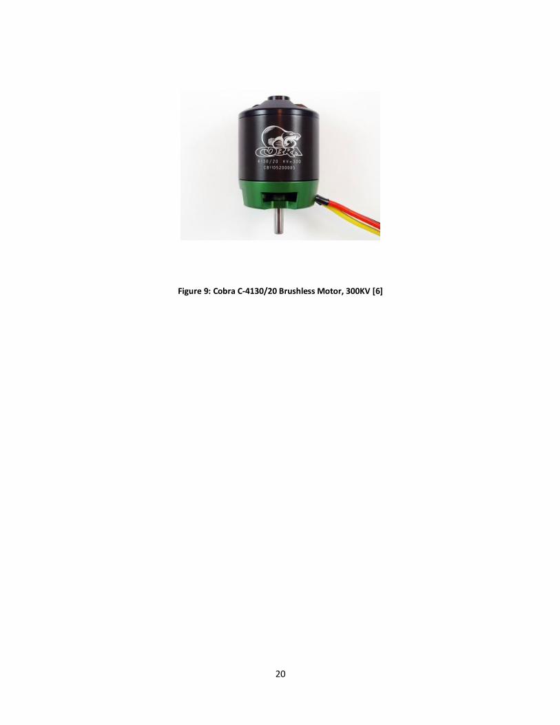
3. Alternative Motor
With any project and design choice there should always be a backup plan. The backup
motor chosen for this aircraft is shown in figure 9. I chose this motor as a backup because it is a
safe option that should give us around 10 lbf of thrust at 750 W. With a similar sizing to the
motor used last year this motor is slightly narrower with a lower KV. The lower KV is what we
were after in this motor. Lower KV means the motor will spin slower allowing for a higher
torque which will allow us to run larger and more aggressive propellers. However it is inferior
to the T-Motor in almost every way except top speed which is why this is the safe backup.
20
Figure 9: Cobra C-4130/20 Brushless Motor, 300KV [6]

21
5. Preliminary Design
Figure 10: Propulsion System Block Diagram
1. Motor Selection
The motor I chose for this airplane is the T-Motor U8 Lite 190 KV shown in figure 11. This
motor is an unconventional motor for this setup because they are designed for use on
quadcopters. The main difference between a conventional motor designed for an airplane and
these drone motors is the number of stators and thickness of the motor. The higher stator
number and the lower thickness of the motor allow for a much higher thrust to power ratio.
First being a thinner motor it can be cooled much more efficiently. Warm motors are a good
thing but you don’t want them getting hot as that will have negative effects on the motor. Next
the high number of stators allow the motor to spin much smoother and more efficiently
because there is less distance between magnets so there is less time the stators are changing
electric fields. The large diameter and low KV also allow us to run much larger propellers such

22
as 26.4 x 9.4 in and 28.4 x 10.1 in. It’s also much lighter than the other motors being
considered such as the E-flite and Cobra motor. It’s actually almost 140 g lighter than the T-
motor and 153 g lighter than the Cobra.
Figure 11: T-Motor U8 Lite 190KV [8]
Motor KV Diameter (mm)
Thickness (mm)
Weight (g)
Price ($)
T-Motor 190 87.1 27.05 243 299.99
Cobra 300 49.8 61.8 396 87.99
E-flite 400 50mm 62 380 109.99 Table 1: Motor Comparison
2. ESC and Connector Selection
I decided to stay with the same brand of ESC used last year which is Castle. I wanted to
downsize from a 90 A to a 60 A ESC because 90 A is just unnecessary for our application.
Overall we will get the same performance while saving 27 g of weight. This will also allow us to
use smaller connectors in the XT60 with 12 AWG wire saving us some more weight.

23
3. Power Limiter and Arming Switch
As part of the SAE rules we must use the one found here [7]. This prevents cheating. I will not
be changing last year’s arming plug setup. The arming plug is just a split in the circuit’s ground
wire which is connected with a T-plug shown in figure 12.
Figure 12: T-plug [9]
4. Receiver Selection
For a receiver we decided to go with the 8-channel FrSky X8R. This would allow us to have
telemetry and have a simple setup with our servos moving control surfaces on a separate
controller than the ones controlling dropping mechanisms. The receiver can be viewed in figure
10.

24
Figure 13: FrSky X8R [10]
5. Battery Selection
Finally we need to power this aircraft. As stated earlier, I wanted to downsize batteries to
save on weight. I will be using a Turnigy Nano-Tech 6S 4000 mah battery. This will save us
about 150 g of weight which is very important when the empty aircraft needs to be less than 10
lbs (4,536 g).

25
6. Final Design and Implementation
1. First Prototype
Figure 14: Propulsion Loop Wiring Diagram
All design iterations used the same wiring shown in the wiring diagram above. The first
prototype was the very first aircraft we built that could support itself, roll and power up. No
changes in parts were made from preliminary design since this is the first prototype. The
propulsion loop was very basic and minimalistic to prove the concept. Everything was designed
to fit in the initial nose cone design and was more of a cluttered mess of wires. I cut wires long
for this iteration since the aircraft design was constantly changing and my propulsion loop
needed to work for any design changes made and any mistakes I made along the way. The
most important part was the battery had to be as far forward as possible for CG purposes. The

26
main difficulty with implementing the design to this aircraft iteration was having a moving part
vital to the aircraft’s performance in the middle of the propulsion loop. The choice to use a
tricycle landing gear setup meant the nose wheel would be placed in the nose cone. This
meant the steering mechanism for the aircraft would be in the middle of a “cluttered mess” of
wires. The temporary fix for this was to tape the wires to the sides of the nose cone.
2. Second Prototype
Figure 15: Second Prototype
The second prototype was exactly the same as the first iteration with the exception of a
new wing bracket and the addition of glider mounts one on each side of the wing. The
propulsion loop stayed exactly the same since the team did not have the data or the time to
develop the next iteration of the aircraft design before our mandatory flight date on March 8th.

27
3. Final Design
The third and final iteration of the aircraft was supposed to have a different motor mount
with a smaller nose cone and all drop mechanisms would be implemented. The changes being
made for the power loop in this iteration was the arming plug placement. This was a challenge
because all the pieces of the aircraft slide on and off of the center spar so I couldn’t just mount
it anywhere on the main spar. It also needed to be 40 – 60 % the length of the aircraft behind
the propeller which is approximately 5.5 ft behind the propeller. The length had to be right the
first time because 5.5 ft of wire costs approximately $ 10. The T- plug had to be mounted
securely to the main spar in between the last rib of the fuselage and the fairing using glue and a
3D printed housing. Since the fairing didn’t have to come off for travel or assembly I could
safely and reliably mount the arming plug in that position. The other change we were
considering was changing our receiver to the Frsky L9R [11]. The reason for this is that at
competition there can be hundreds of transmitters and receivers on at one time which creates
a very noisy environment. The Frsky L9R has much better antennas which allow for a better
more consistent connection. The reason we wanted to upgrade the receiver antenna and not
the transmitter antenna is due to companies not producing better antennas for their
transmitters. I looked into possibly modifying it myself but found I would risk ruining the
transmitter for a marginal increase in performance.

28
7. Performance Estimates and Results
1. Preliminary Estimates and Testing Results (Fall Term)
I was able to do some initial testing with the T-Motor on our test stand. I only used two
different propellers as they are very expensive and don’t come in many sizes for the budget
options. Thrust and watt results for the testing can be found in figures 14 and 15. As you can
see we were not able to test the full capability of this motor as its performance exceeds the
maximum thrust limitations of the test stand. I looked into other test stands but they are over
$5,000 which is out of our price range. I have looked into building my own and will talk to my
teammates and see if this could be a practical option to pursue. I am planning to experiment
with counter weighting the thrust accelerometer using a spring or a pendulum after we move
to the new building.
These results are very exciting as we have exceeded last year’s motor performance by an
incredible margin at nearly half the wattage. The amount of weight might increase by a
significant margin in the near future if initial flight tests go well.
Figure 17: T-Motor 190KV/26.4x9.4in propeller

29
Figure 18: T-Motor 190KV/28.4x10.1in propeller
2. Final Testing Results (Winter Term)
I was able to find a way to measure motor thrust at 750 W using the existing thrust stand
but it was at the cost of torque measurements. The work around was offsetting the
dynamometer with a spring scale. This is not a perfect solution but was the only time and cost
effective work around available. The other side effect was arbitrary points on the graph due to
data recording differences between power and thrust and oscillations in the thrust stand due to
the spring used to offset the dynamometer. The results are shown in figures 19 and 20.
We were able to conduct one takeoff test where we could measure speed and distance
and we found that to be roughly 20.4 mph and 30 ft. We had one successful flight but received
no speed data because crashes are common during initial flight testing and we did not want to
lose expensive electronics in the event of a crash.

30
Figure 19: T-Motor 190KV/26.4x9.4in propeller 800 W test
Figure 20: T-Motor 190KV/28.4x10.1in propeller 800 W test

31
8. Production Schedule
1. Initial aircraft prototype construction – January
2. Initial propulsion loop built in January
3. Motor testing with constructed loop on thrust stand from January - February
4. Airframe trouble shooting from beginning of February – beginning of March
5. Transmitter/receiver range testing – February
6. Taxi test – mid February (successful)
7. Fixing wing mounts and strengthening control surfaces from mid-February – beginning
of March
8. First flight 3/8/20 (very successful, no crash)
9. Construction of new propulsion loop with correct arming plug placement planned
3/13/20 (cancelled)
10. Flight test, new propulsion loop and drop mechanism implementation planned for
3/15/20 (cancelled)
11. SAE AERO west competition – April 3-5, 2020 (cancelled)
I did all I could during production as I was constructing and testing my own design while
helping with other aspects of airframe construction. Most of my time went to helping fix
problems which arose with the airframe. The final iteration of the aircraft was never
constructed due to rising health concerns. However a very promising prototype was
constructed and successfully tested.

32
9. Cost Analysis
Table 3: Cost to Performance T-Motor
Table 4: Cost to Performance Cobra
In figures 3 and 4 I outline cost to performance for the two selected motors and
propellers considered. Figure 5 shows the total cost to construct this propulsion system. Cost
may vary when buying plugs and wire since they must be purchased in bulk and prices will vary
between different brands.

33
Product Price ($)
T-motor U8 Lite 299.99
28.4 x 10.1 in propeller 79.99
Castle Talon 60 A ESC 69.95
SAE AERO Watt Limiter 75.00
Turnigy 6S battery 53.97
Frsky X8R reciever 35.90
Plugs and wire 37.85
Total 652.65
Table 5: Total Cost of Propulsion System

34
10. User’s Manuel
1. Tools Needed
Allen wrench size 2.5 (metric)
Allen wrench size 2 (metric)
Soldering iron for general repair
2. Assembly
XT-60 plugs and T-plugs can only be connected one way. When connecting the motor to the
ESC there are three wires the center wire on both must be connected to each other and the
outer two choose motor direction. You want the motor spinning counterclockwise if standing
behind it. If it is spinning clockwise simply reverse the outer wires. The ESC should then
connect to the power limiter using the XT-60 connector. The power limiter should then
connect to the battery and arming plug. Finally the small servo connector coming off the ESC
plugs into channel one of the receiver. Yellow wire should be the top wire if the receiver’s logo
is face up. Now using the allen wrench size 2.5 connect the motor to the aircraft using provided
screws. After connecting the motor use supplied screws to connect the propeller to the motor
using the allen wrench size 2. If you have trouble attaching the propeller to the motor you can
visit the manufacturer page for the motor [9].
3. Operation
After assembly be sure to leave the battery and arming plug disconnected. Pair your
receiver with a compatible Frsky transmitter. Once that is paired you will need to change a few

35
settings to allow you to control the motor. After your transmitter is setup and turned on
connect the battery. Then at a safe distance behind the propeller connect the arming plug to
turn on the system. Once on you should be able to control the motor speed with the
transmitter. Once operation is complete leave the transmitter on and unplug the arming plug
at a safe distance behind the propeller. Next unplug the battery and once the battery is
unplugged turn off the transmitter.
4. Maintenance
The only maintenance for this system is making sure your connections are good and not
loose, the motor is not damaged in the case of a crash and battery health. Battery health is
incredibly important when using LIPO batteries. Max cell voltage should not exceed 4.2 V and
minimum cell voltage should not go below 3.2 V. After use you should set your cell voltage to
3.8 V. This is considered a safe voltage to store your batteries if you’re not planning to use
them for an extended period.

36
11. Conclusion
Participating in the SAE AERO event is always the end goal of this project. Winning or
placing highly would be nice but getting there is the priority. Through testing we’ve seen that
we may have the best airframe but an un-optimized motor propeller combo can ruin it. That is
why I set out to find something that would allow my team to push the limit on what could be
done.
Selecting a motor was difficult due to a lack of information on the type of flying we were
trying to do. The initial decision came down to a few calculations and data sheet observations.
Once I made an initial decision it was time to test on the test stand. Due to the inferior
capability of the test stand I was forced to find a work around. This work around consisted of
offsetting the dynamometer with a spring to trick the software that thrust limits weren’t being
exceeded. After this a loop consisting of parts listed earlier was constructed and secured to the
aircraft in the nose cone. We conducted one successful flight and are sad to say we did not
have the ability to conduct another due to COVID-19 restrictions.
I’m not sure I would make the same choice with the information I know now. I’m
confident in my choice from a performance stand point but would rather have chosen my other
option from a price stand point. The $200 price difference between the two motor and
propeller combinations does not justify the performance increase. If you factor in that we
needed at least three motors and propellers that’s $600 we could have saved. This is very
significant to the fact that crashes are common in this hobby and the T-motor is much more
delicate than the Cobra. This could prove to get very expensive if only a few hard crashes

37
occur. However with that said I DO NOT regret my decision. This was amazing information to
discover and pass to next year’s senior team. It tells them that yes, this is a great option but
has some large drawbacks.
This project taught me how to work in a group over an extended period. This is vastly
different from having a lab partner or doing a group project for a couple weeks. We were stuck
with each other for a year and we had to get along (most of the time). I found that I was
working on things other than my project more often than expected but this was necessary to
meet deadlines. Team projects aren’t all about your part they are about the team’s part. If
others need help you should help them if possible.

38
12. References
[1] 2020 SAE Aero Design Rules, Accessed on Nov. 24, 2019. Available: https://www.saeaerodesign.com/cdsweb/gen/DocumentResources.aspx
[2] RCbenchmark Series 1580 Thrust Stand, Accessed on Nov. 24, 2019. Available: https://www.rcbenchmark.com/products/dynamometer-series-1580?variant=13071468527728
[3] Power 60 Brushless Outrunner Motor, 400Kv, Accessed on Nov. 24, 2019. Available: https://www.horizonhobby.com/power-60-brushless-outrunner-motor--400kv-eflm4060a
[4] OliYin 3pcs XT90 Male to XT60 Female Connector plug, Accessed on Nov. 24, 2019. Available: https://www.amazon.com/OliYin-Connector-Converter-Adaptor-Electric/dp/B07C7SVT8G/ref=asc_df_B07C7SVT8G/?tag=hyprod-20&linkCode=df0&hvadid=309770211034&hvpos=1o3&hvnetw=g&hvrand=10216417250334753516&hvpone=&hvptwo=&hvqmt=&hvdev=c&hvdvcmdl=&hvlocint=&hvlocphy=9004717&hvtargid=pla-644215743566&psc=1
[5] G. Staples, Propeller Static & Dynamic Thrust Calculation, July 2013. Accessed on: Nov. 24, 2019. [Online]. Available: https://www.electricrcaircraftguy.com/2013/09/propeller-static-dynamic-thrust-equation.html
[6] Cobra C-4130/20 Brushless Motor 300KV, Accessed on Nov. 24, 2019. Available: https://www.cobramotorsusa.com/motors-4130-20.html
[7] Cobra C-4130/20 Motor Propeller Data http://www.innov8tivedesigns.com/images/specs/Cobra_4130-20_Specs.htm
[8] Dean Connector T Plug, Accessed on: Nov. 24, 2019. Available: https://www.robomart.com/buy-dean-connector-t-plug-for-esc-battery-india
[9] T-Motor U8 Lite 190KV, Accessed on: Nov. 24, 2019. Available: http://store-en.tmotor.com/goods.php?id=470
[10] FrSky Taranis Compatible Receiver X8R, Accessed on: Nov. 24, 2019. Available: https://www.amazon.com/FrSky-Taranis-Compatible-Receiver-8-Channel/dp/B00RCAHHFM/ref=asc_df_B00RCAHHFM/?tag=hyprod-20&linkCode=df0&hvadid=242048352875&hvpos=1o2&hvnetw=g&hvrand=12170770719632718347&hvpone=&hvptwo=&hvqmt=&hvdev=c&hvdvcmdl=&hvlocint=&hvlocphy=9004717&hvtargid=pla-588530700237&psc=1
[11] FrSky L9R, Accessed on: Mar. 15, 2020. Available: https://www.frsky-rc.com/product/l9r/

39
13. Appendices
Table 2: Manufacturer Thrust Data [7]

40
Figure 16: Thrust decrease with speed [10]


