[email protected][email protected]whatsapp:959440045 OM English EN OPERATOR’S MANUAL OPERATION SERVICE MAINTENANCE Decanter Centrifuge Alfa Laval Alfa Laval Original instruction h FRONT www.fdm.com.pe
Frame and Casing Material - casing / cover: Stainless steel (AISI 316) Inside surface of casing: Liners of stainless steel at discharge areas - painting in
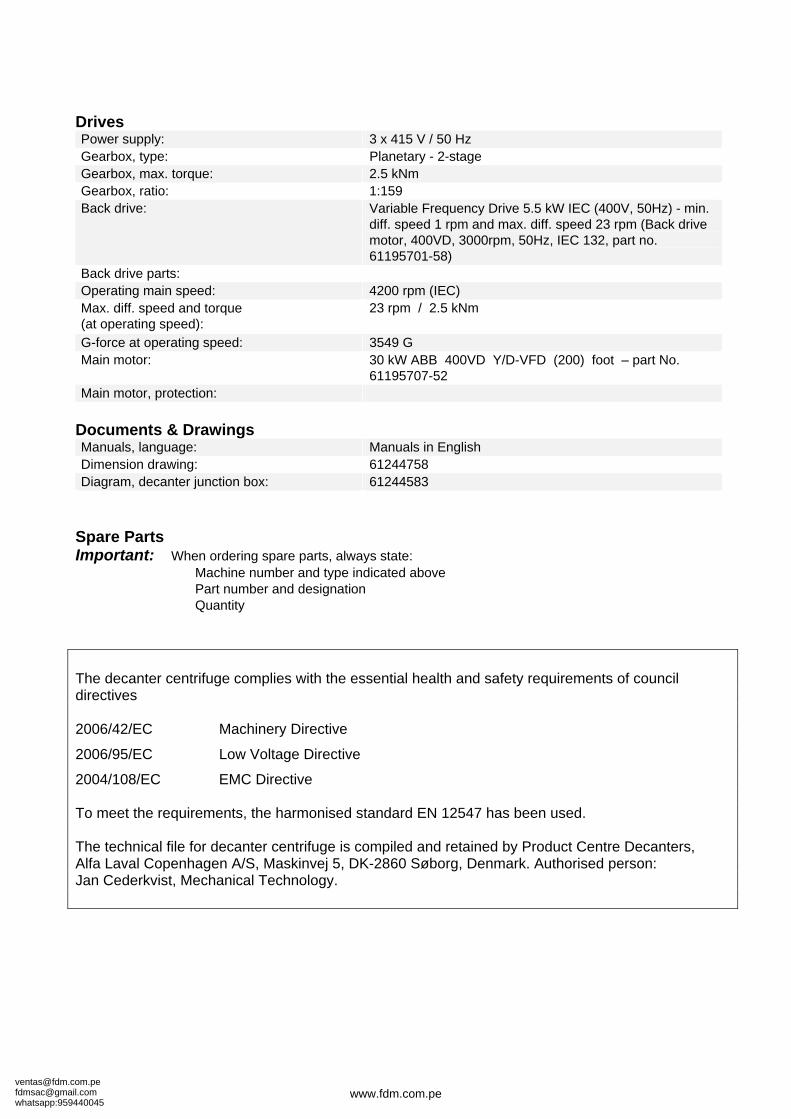
Back drive parts: Operating main speed: 4200 rpm (IEC) Max. diff. speed and torque (at operating speed):
23 rpm / 2.5 kNm
G-force at operating speed: 3549 G Main motor: 30 kW ABB 400VD Y/D-VFD (200) foot – part No.
61195707-52 Main motor, protection:
Documents & Drawings Manuals, language: Manuals in English Dimension drawing: 61244758 Diagram, decanter junction box: 61244583
Spare Parts Important: When ordering spare parts, always state:
Machine number and type indicated above Part number and designation Quantity
The decanter centrifuge complies with the essential health and safety requirements of council directives 2006/42/EC Machinery Directive
2006/95/EC Low Voltage Directive
2004/108/EC EMC Directive To meet the requirements, the harmonised standard EN 12547 has been used. The technical file for decanter centrifuge is compiled and retained by Product Centre Decanters, Alfa Laval Copenhagen A/S, Maskinvej 5, DK-2860 Søborg, Denmark. Authorised person: Jan Cederkvist, Mechanical Technology.
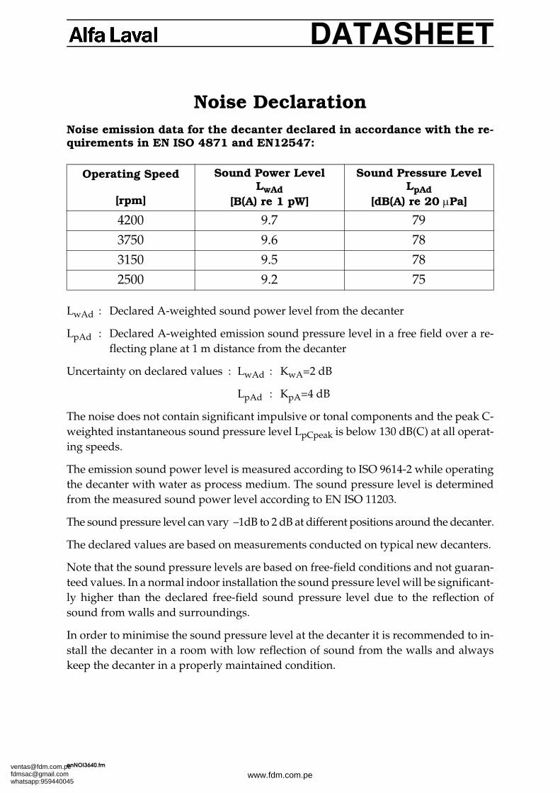
Noise Declaration Noise emission data for the decanter declared in accordance with the re-quirements in EN ISO 4871 and EN12547:
LwAd : Declared A-weighted sound power level from the decanter
LpAd : Declared A-weighted emission sound pressure level in a free field over a re-flecting plane at 1 m distance from the decanter
Uncertainty on declared values : LwAd : KwA=2 dB
LpAd : KpA=4 dB
The noise does not contain significant impulsive or tonal components and the peak C-weighted instantaneous sound pressure level LpCpeak is below 130 dB(C) at all operat-ing speeds.
The emission sound power level is measured according to ISO 9614-2 while operatingthe decanter with water as process medium. The sound pressure level is determinedfrom the measured sound power level according to EN ISO 11203.
The sound pressure level can vary –1dB to 2 dB at different positions around the decanter.
The declared values are based on measurements conducted on typical new decanters.
Note that the sound pressure levels are based on free-field conditions and not guaran-teed values. In a normal indoor installation the sound pressure level will be significant-ly higher than the declared free-field sound pressure level due to the reflection ofsound from walls and surroundings.
In order to minimise the sound pressure level at the decanter it is recommended to in-stall the decanter in a room with low reflection of sound from the walls and alwayskeep the decanter in a properly maintained condition.
2.1 Main Drive ...................................................................................... 2.1-1
2.2 Back Drive ...................................................................................... 2.2-12.2.1 Variable Frequency Drive Back Drive (VFD) ............................... 2.2-1
3 Operation and Routine Maintenance .................... 3.1-1
3.1 Before First Start ........................................................................ 3.1-13.1.1 Noise and Vibrations ........................................................................ 3.1-2
3.6 Main Drive ...................................................................................... 3.6-1
3.7 Variable Frequency Drive (VFD) ............................................ 3.7-1
3.8 Lubrication ..................................................................................... 3.8-13.8.1 Lubrication of Main Bearings .......................................................... 3.8-13.8.2 Lubrication of Conveyor Bearings ................................................. 3.8-4
3.8.2.1 “Solid Oil” Conveyor Bearings (optional)3.8.3 Change of grease type - Compatibility of greases ....................... 3.8-53.8.4 Cleaning out grease exits on decanters .......................................... 3.8-53.8.5 Grease accepted by Alfa Laval
for lubrication of decanter bearings ............................................... 3.8-53.8.6 Gearbox .............................................................................................. 3.8-7
3.9 Recommended service intervals .......................................... 3.9-1
4 Disassembling and Assembling ................................... 4.0-1
4.1 Rotating Assembly ...................................................................... 4.1-14.1.1 Remove Bowl ..................................................................................... 4.1-14.1.2 Install Bowl ........................................................................................ 4.1-34.1.3 Remove Large End Hub ................................................................... 4.1-54.1.4 Install Large End Hub ...................................................................... 4.1-54.1.5 Remove Small End Hub ................................................................... 4.1-74.1.6 Install Small End Hub ...................................................................... 4.1-74.1.7 Remove Gearbox ............................................................................... 4.1-84.1.8 Install Gearbox .................................................................................. 4.1-94.1.9 Fit New Wear Liners ........................................................................ 4.1-10
4.2 Main Bearings ............................................................................... 4.2-14.2.1 Disassemble Main Bearing Large End ........................................... 4.2-14.2.2 Assemble Main Bearing Large End ................................................ 4.2-34.2.3 Disassemble the Main Bearing Small End ..................................... 4.2-54.2.4 Assemble Main Bearing Small End ................................................ 4.2-6
4.3 Conveyor Bearings ...................................................................... 4.3-14.3.1 Disassemble Conveyor Bearing Large End ................................... 4.3-14.3.2 Assemble Conveyor Bearing Large End ........................................ 4.3-34.3.3 Disassemble Conveyor Bearing Small End ................................... 4.3-54.3.4 Assemble Conveyor Bearing Small End ........................................ 4.3-6
4.4 Conveyor ......................................................................................... 4.4-14.4.1 Remove Conveyor from Bowl ......................................................... 4.4-14.4.2 Insert Conveyor into Bowl ............................................................... 4.4-2
4.5 Main Drive ...................................................................................... 4.5-14.5.1 Disassemble Main Drive .................................................................. 4.5-14.5.2 Assemble Main Drive ....................................................................... 4.5-34.5.3 Tighten V-belts, Belt Tension Tables .............................................. 4.5-4
Alfa Laval Rev. 2005-05 OM1.01 Safety Instructions
1 Safety Instructions
1.0
The Decanter
1. The decanter delivered must not be used to separate flam-mable, toxic, corrosive, or radioactive process mediawithout prior written approval from Alfa Laval.
2. Read this manual and the Operator's Manual before at-tempting to install or operate the decanter equipment,and follow all recommendations.
3. Do not operate the decanter with damaged or missingwarning labels.
4. Do not operate the decanter if the vibration level exceeds24 mm/sec (RMS) (US: 1 inch/sec).
5. Do not operate the decanter with feed temperatures ex-ceeding the limits stated on the DATA SHEET included inall three volumes of the Instruction Manual.
6. Never attempt to start the decanter with frozen water orfrozen or hardened process material in the bowl.
7. Do not exceed the maximum bowl speed or solids densityspecified on the decanter name-plate and DATA SHEET.
8. Do not operate the decanter without belt guards and otherguards provided.
9. Periodically check all the automatic shut-off devices andmonitoring systems for correct operation.
contd...
FAILURE TO FOLLOW THESE RULES MAYRESULT IN SEVERE PERSONAL INJURY ORPROPERTY DAMAGE.
Alfa Laval Rev. 2005-05 OM10. Do not attempt dismantling until the decanter has come
to a complete stop, the main power is shut off, and the dis-connected main switch is locked with a safety lock.
11. Do not operate the decanter if the bowl, motor, or sup-porting structure show cracks, pitting, holes, or grooves.
12. Do not use tools other than those recommended by AlfaLaval to dismantle and assemble the decanter.
13. Do not attempt to use the decanter for any application orprocess material other than that stated on the original pur-chase documentation without first consulting Alfa Laval.
14. Follow all lubricating procedures and schedules.
15. Check periodically - at least once a year - for loose bolts onfoundation and supporting structures, covers, hatchesand pipe connections of decanter and motor.
16. Do not get rags or loose clothing near rotating parts.
17. At all times follow the recommended sequence and proce-dures for dismantling, assembly, operation, and mainte-nance. Do not introduce new procedures without firstconsulting Alfa Laval.
18. Only allow trained personnel to operate, clean, dismantleor assemble the decanter.
19. Do not operate the decanter before the installation is com-plete.
20. Do not operate the decanter with any electrical motor run-ning in the opposite direction to that indicated by the ar-rows on the frame or otherwise specified.
Alfa Laval Rev. 2005-05 OM21. If the decanter is fitted with a frequency inverter, make
sure that the maximum possible frequency will not causeoverspeeding of the decanter. At least two separate pro-tections against overspeed must be provided. See section6.9.
22. Do not turn on feed or water before the decanter has at-tained its full speed.
23. If the decanter is operated with hot, corrosive, or aggres-sive liquids, care should be taken that any incidental spill-age from the decanter cannot hit persons below the centreline of the decanter.
24. Never turn on feed or large amounts of hot, corrosive, oraggressive liquids when the decanter is at a standstill, asthese liquids might hit persons below the centre line of thedecanter.
25. Never start the feed pump or flush the decanter beforeopening the discharge valves or starting the dischargepumps, including any conveying means for the liquid andsolids phases.
26. When personnel are working on a decanter with a hingedcover, care should be taken that the cover is not closed un-intentionally by other persons or by moving machinery,which might cause injury.
27. Do not touch the solids phase discharging from the de-canter as hard lumps being ejected with high speed mightcause injury.
28. When using straps to lift the complete decanter or any ofits parts such as the rotating assembly, make sure to pre-vent the part hanging by the straps from sliding.
29. When lifting the decanter, use the slings specified on thedimensioned drawing.
30. The lifting eyes in the bearing housings, if fitted, must notbe used for lifting the bowl assembly.
1. Install and earth all equipment in accordance with re-quirements of the Local Electricity Authority.
2. Use an “on-load” isolator or circuit breaker (a main switchfor switching off during run-up) on the main power sup-ply.
3. Check that the voltage and the frequency are in agreementwith labels on motors and other electrical equipment.
4. De-energize all equipment before connecting and discon-necting test equipment.
Repairs
1. Major repairs to decanter must not be made without firstconsulting with Alfa Laval.
In no circumstances should weld repairs, heating witha naked flame, or other alterations be made to bowl shells,bowl hubs, gearbox adapter, shafts, or other rotating partswithout prior written approval and instructions fromAlfa Laval. Failure to obtain this approval may result infailure of parts involved with possible serious damage toequipment, property, or personnel.
2. Do not operate the decanter on completion of the repairsuntil the belt and/or other guards are re-fitted.
Alfa Laval Rev. 2005-05 OM3. Do not exceed the maximum load carrying capacity of the
lifting tools. Only use the lifting tools for the intendedpurpose.
4. Replace worn or damaged parts with only originalAlfa Laval parts.
Alfa Laval cannot be held responsible for any damageto property or for injury to persons if genuine parts arenot used.
5. Do not interchange bowl parts, since specific parts are bal-anced as a unit.
The Motor
1. Do not operate a decanter equipped with flame proof mo-tor(s) and control unit(s) until all enclosures have been as-sembled in accordance with the appropriate standards.
2. If a motor should become inoperative, immediately shutoff the power.
3. Always follow motor manufacturer's specifications onbearing lubrication.
4. Do not attempt to operate a motor that is overheated dueto frequent starts and stops. Allow motors to cool to am-bient temperature (as designated on the motor name-plate) before each restart.
Do not attempt to start motor unless the rotating elementsturn freely.
Alfa Laval Rev. 2005-05 OMCorrosion, Erosion and Pitting of DecanterEquipment It should be recognized that equipment sub-jected to severe erosive or corrosive environments may deteri-orate over a period of time, depending upon the severity of ex-posure and/or possible misuse. Users of high speed centrifu-gal equipment should be aware of this fact and also that ex-tremely high forces are brought into play when their equip-ment is in operation. Any weakening of highly stressed mem-bers by misuse, erosion, corrosion, chemical pitting, or stresscracking must be guarded against.
The following points should be noted and the recom-mended action taken:
1. Inspect the outside of the bowl for erosion and corrosion,at least every two months.
2. Do not operate equipment when:
2.1 Holes are worn through rotating parts.2.2 Grooves greater than 2 mm (0.08 inch) deep are worn
in rotating parts.2.3 Evidence of cracks is present in rotating parts.2.4 Chemical pitting of 2 mm (0.08 inch) depth or greater
is present on rotating parts.
3. Chemical Pitting Observed:
All cases of chemical pitting, even under 2 mm depth,should be monitored carefully. This action is almost al-ways due to the breakdown of the passive film on stain-less bowl shell walls, in the presence of chlorides. This of-ten occurs under deposits that have not been cleaned fromthe outside of the bowl wall. High temperature and highacidity accelerate the action.
4. Pay special attention to the bolts assembling the bowl sec-tions. If the process liquid or cleaning agents contain chlo-rides, check these bolts at least once a year and exchangethem at least every three years. Contact Alfa Laval, if indoubt.
Contact Alfa Laval regarding the repair or replacement of pit-ted bowl shells or other parts.
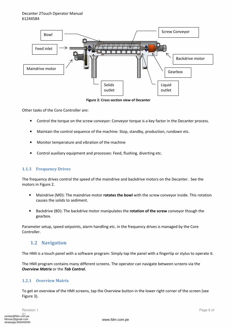
The feed enters the decanter at the intersection of the conicaland the cylindrical part of the bowl through a central feed pipein the hollow drive shaft. After leaving the feed pipe, the feedsuspension is distributed into the rotating liquid in the bowland smoothly accelerated to the full rotational speed. The cen-trifugal force makes the solids settle at the bowl shell. Thescrew conveyor continuously transports the solids toward theconical end of the bowl and through conical bowl part.
The separation takes place throughout the total length of thecylindrical part of the bowl, and the clarified liquid dischargesat the large end where it flows over the rim of exchangeableand/or adjustable plate dams or power tubes.
The solids are discharged from the small end by centrifu-gal force through outlet openings.
Decanter with Baffle DiscThe space in the cylindrical and conical parts of the bowl, withthe baffle disc between them, act as two communicating ves-sels. The plate dams or the power tubes can be set to a smallerradius than that of the solids discharge (negative beach).
Then the heavy phase (the solids) is pressed under thebaffle disc by the hydrostatic pressure of the light phase (theclarified liquid).
ATTENTION The liquid and the solids are discharged at roughly the same radius,and consequently, during start-up, flushing, and irregularities inprocess, discharge of liquid through the solids discharge ports mayoccur owing to lack of solids in the bowl. This should be taken intoconsideration when the decanter is installed.
The decanter is driven by an electric motor. The motor shaftcarries a drive pulley, and motive power is transmittedthrough V-belts to the bowl pulley to drive the bowl.
The purpose of the back drive system is to make it possible tocontrol the speed of the sunwheel shaft of the gearbox andconsequently to control the differential speed between bowland conveyor.
The differential speed is controlled by a decanter controller,which takes care of all basic control funtions related to the de-canter.
For further details, see the specific controller manual.
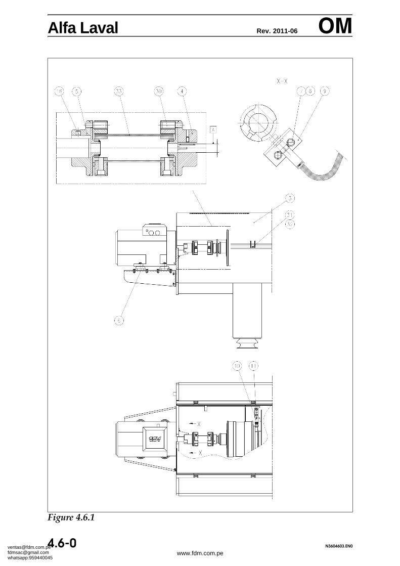
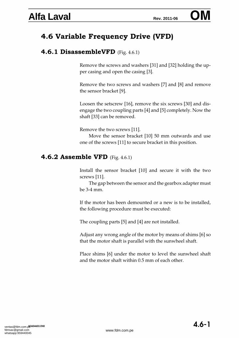
2.2.1 Variable Frequency Drive (VFD) Back Drive
The VFD direct drive system consists of three main electricalcomponents: the Control system, a VFD (Variable FrequencyDrive), and an AC motor. The motor is connected to the de-canter gearbox with a flexible coupling.
The motor speed signal is sent from the controller to the VFD.The VFD then controls the speed of the motor. The controllercalculates the differential speed, based on the measured motorspeed. To determine the differential speed, the controllerneeds information about the gearbox ratio.
The bowl speed and the sunwheel speed is measured by in-ductive speed sensors located on the decanter.
If the motor has to brake to obtain the set speed, then the brak-ing power could either be dissipated as heat in a resistor bank,or in case of a full four quadrant inverter be fed back on thegrid. If a VFD is also used for the main drive, then the powercould be fed back via a DC link between the main and backdrive inverters.
The back drive controller is master of the system, and calcu-lates the speed command signal based on the measured differ-ential speed and conveyor torque. To determine the differen-tial speed, the controller must have information about the gearratio, and measure both speed and direction of the motor/sunwheel shaft and the speed of the bowl.
Alfa Laval Rev. 2011-06 OMThe bowl speed is measured by an inductive speed sensor lo-cated on the decanter, and the sunwheel or motor speed anddirection of rotation is either determined by using two sepa-rate inductive speed sensors, or if an encoder is used, from oneof the channels of the motor encoder.
WARNING Care must be taken when setting up operational parameters.
Firstly, it must be ensured when setting up the speed range for thevariable speed motor that the conveyor can never rotate as fast as orgreater than the bowl speed. This could result in a plugged or cloggeddecanter and could even mean a risk of overspeeding the bowl. Thebowl speed is determined by the type of decanter and the process.
Secondly, it must also be ensured that the maximum load does notexceed the gearbox rating. This will result in damage to the gearboxand pinion shaft. The maximum gearbox load depends on the sizeand type of gearbox fitted.
Ensure that the transport safety devices (the yellow wedges) have beenremoved. Check that the bowl rotates freely in both directions.
Read all manuals before starting the decanter. Pay special attention to the safety instructions and the procedures for
electrical and mechanical installation of the decanter.
ATTENTION Because the main bearings are filled with grease from the factory, therunning-in procedure described in section 3.8 must be followed inorder to avoid temperature problems.
Alfa Laval Rev. 2009-12 OM3.1.1 Noise and Vibrations
In spite of the most accurate balancing a rotating body is always slightlyout of balance. As the bowl and the conveyor are two separately bal-anced units rotating at different speeds, the negligible unbalance ofeach unit will coincide, and a momentary increase of noise and vibra-tion occurs in the machine.
The period of time between the moments when this happens dependson the difference in the speeds of bowl and conveyor. The higher thedifferential speed the shorter the intervals, and vice versa.
Increased unbalance caused by wear and/or accumulation of solidswill increase the amplitude of noise and vibration.
A practical hint: The differential speed of the conveyor can be found bycounting these vibrations for exactly one minute.
Alfa Laval Rev. 2000-03 OM3.2 Start/Stop procedures
3.2.1 Inspect Bowl
A bowl which has not been cleaned, but left clogged by solidsafter operation must be cleaned before the decanter is restart-ed, because dried solids may cause severe unbalance andeventual generation of an overload condition. See section3.3.1.
3.2.2 Before Start
3.2.2.1 Checkpoints
If the decanter has stopped due to overload, the followingpoints must be checked before the decanter is started:
• Are the upper and lower casings free from solidsdeposits?
• Are the discharges open?
• Is the bowl easily rotated by hand?
• Are all guards correctly placed and properly secured?
3.2.2.2 Decanters with Mechanical Seals(Optional Equipment)
Before starting a decanter with mechanical seals, the gas sup-ply system for the seals must be activated and the flow andpressure of gas to the seals must be checked. If the decanter isto be used for inflammable substances, it must be purged withinert gas and it must be ensured that the oxygen concentrationhas gone down to a safe level before the machine is started.Also during run-down until the decanter has stopped, the gassupply to the seals must be activated. See section 3.10.1 ’Instal-lation, Start-up and Operation of Decanters with Circumfer-ential Seals’.
Release EMERGENCY STOP (in most cases: pull out theEMERGENCY STOP knob - or turn it as indicated by arrows).
Start the decanter motor.
Wait 2-4 minutes for the decanter to attain full speed with starconnected circuit before switching to delta connected circuit.
Start the belt conveyor or other transport means for dis-charged solids.
Open the feed valve (if any).
Start polymer pump (if used).
Start the feed pump.
3.2.4 Stop Decanter
ATTENTION When stopping a decanter with mechanical seals make sure that thesupply of gas continues until the decanter has stopped.
Stop feed and polymer pumps (if used), close feed valve (if fit-ted).
Before stopping, flush out with water of suitable temperature.Flush while the machine is running.
Stopping the decanter before its bowl is sufficientlycleaned may give rise to heavy vibrations both during decant-er rundown and during its successive run-up.
ATTENTION When flushing decanters for fat and oil applications, optimal flushingeffect is achieved by using flushing liquids holding temperatures abovethe melting points of the fats and oils run through the decanter.
Using e.g. cold water might cause solidified lumps of fat/oils to re-main in the decanter, which in their turn would give unbalance duringdecanter rundown and during its successive run-up.
Stop the decanter motor when the bowl is thoroughly flushed.Do not flush the decanter when it is inactive.
Press the CENTRIFUGE STOP button on operator panel.
Alfa Laval Rev. 2012-02 OM3.3 Monitoring Operation
Make particularly sure that there is no increase in vibration.
Check the surface temperature of the main bearing housings fromtime to time. A temperature rise may indicate a possible malfunc-tion in the bearing.
ATTENTION The alarm level for main bearing temperature is 110°C (230°F). Atthis temperature level the bearing must be monitored. Especially ifthe increase of temperature is very steep or appears without any ob-vious reason such as after lubrication of the bearing or increased feedor ambient temperature.
The shut down level is 120° C (248°F). At this temperature the de-canter must shut down immediately. If after a restart the tempera-ture again increases to 120°C (248°F), the bearing must be replaced.
After lubrication the temperature may remain high for some hours.
3.3.1 Overload
If the centrifuge torque exceeds a certain limit, the control systemwill deactivate the feed permissive contact and stop the feed andpolymer pumps.
Under these circumstances the control system can be reset andthe feed pump restarted from the control panel.
If the conveyor torque exceeds a higher limit, the main motor willbe also be switched off.
Then it is advisable to have the feed replaced by water until thebowl speed has reached 300 r p m.
When the bowl has stopped rotating, reset the control system tooperative condition.
Alfa Laval Rev. 2012-02 OM3.3.1.1 Causes of Overload
The causes of overload may be:
• Too high throughput.
• Too high feed concentration.
• The properties of the solids (prestraining or grinding the proc-ess liquid before feeding it into the decanter may be necessary).
• Too low differential speed.
• Solids clogging the discharge from the casing. (Main motor overload.)
• Too high bowl speed.
3.3.1.2 Cleaning an Overloaded Bowl
If the decanter has stopped due to too high torque on the conveyor,and the decanter is unable to scroll itself free during a new start, orwhen running CIP with an AC back drive, the causes of overloadmay be as described above, and the only way to clean the bowl willbe to disassemble the bowl according to instructions given in sec-tion 4.4.1.
When cleaning the conveyor, be careful to clean all of the flights toavoid unbalance when running the decanter after assembly.
ATTENTION It is forbidden to attempt to eliminate the overload on a decanter witha standard gearbox by fixing the sunwheel shaft and rotate the bowl,or on a decanter with DD gearbox to use spanners or the like to rotatethe sunwheel shaft, due to the fact that it can cause damage on eitherthe gearbox, the spline shaft or the large end hub.
If excessive vibrations occur while the bowl rotates, stop the mainmotor immediately and supply liquid to soften the vibrations.
3.3.2.1 Vibration Switch (Optional Equipment)
To protect the decanter against damage due to heavy vibration, itcan be equipped with a vibration sensor which cuts off the powersupply to the main motor and the feed pump in case of excessive de-canter vibrations.
The control panel (or the motor starter) must be provided witha terminal for the vibraswitch.
Being erected on vibration dampers, the decanter deflectsgreatly during starting and stopping, but these oscillations are sosoft that they will not activate the vibraswitch.
Four types of vibration switches are available:
2Touch Vibration Sensor
The 2Touch control system is equipped with two vibration sensors.One sensor is placed on each bearing house.
See 2Touch manuals for more information on 2Touch vibrationsensors.
IFM Vibration Sensor
Shut down RMS is set to 24 mm/sec (0.9 in/sec).Alarm RMS is set to 18 mm/sec (0.7 in/sec).Delay is set to 5 sec.
4-20 mA vibration signal from IFM sensor equals 0-50 mm/secRMS.
Alarm levels are set in external control equipment or limitswitch with two outputs.
Vitec Vibration Switch
The standard factory-set levels are 19 mm/sec (0.7 in/sec) for alarmlevel and 31 mm/sec (1.2 in/sec) for decanter shutdown level.
For further details about the vibration switch, see sub-suppli-er's descriptions included in the decanter supply.
Alfa Laval Rev. 2012-02 OMRobertshaw Vibration Switch (Fig. 3.3.1)
ResettingThis vibration switch is reset manually by pressing the reset button,see figure 3.3.1 below
AdjustingTo adjust this vibration switch to trip at the correct vibration level,proceed as follows:
When the decanter is not operating, turn the adjusting screw clock-wise until the vibraswitch trips.
Then reset it and find the tripping point again. Repeat this pro-cedure a couple of times to ensure that the correct tripping point hasbeen found.
Then turn the adjusting screw counterclockwise one time and athird.
ATTENTION Re-adjustment may be required if the vibraswitch shuts off the powersupply because the building where the decanter equipped with vi-braswitch is operating begins to vibrate heavily.
Figure 3.3.1 Resetting the Robertshaw Vibration Switch
Alfa Laval Rev. 2010-08 OM3.4 Routine Cleaning Procedure
Before starting a cleaning process, please note that the belowprocedure is not product specific and therefore is only intend-ed as a guide.
Before the decanter is stopped, close the valve to the feed andraise the differential speed, if possible, in order to transportthe last solids remains out of the bowl. Always make sure totake precautions against outflow of fluids to other machineswhich provide further treatment of the solids after the separa-tion process, such as for instance sludge drier or the like. Thiscan be done by redirecting the decanter's slide gates or by-passsystem.
Instructions:
1. Flush the decanter with water until the discharged flush-ing water from the large end looks clean and clear.
ATTENTION On decanters with paring disc the flow must not exceed the capacityof the paring disc.
2. Switch off the main motor, but continue to flush. Shut offthe water before the bowl speed decelerates below 300rpm.
3. Open the upper casing of the bowl and check visually ifboth upper and lower casings are clean. Check also ifthere is still product in the bowl. This is done by lookinginto the bowl through the holes of the large end hub andthe solids discharge.
4. Now check if the flushing had the intended effect on thebowl. This is done by turning the sun wheel shaft by handwithout moving the bowl.
Alfa Laval Rev. 2010-08 OM5. If item 3 and item 4 are not satisfactory, the decanter must
be accelerated to operating speed again, and the proce-dure is repeated from item 1. If it is not possible to prop-erly clean the bowl according to the above procedure, thebowl must be disassembled and then cleaned.
After having done the above procedure, the observationsshould be evaluated regarding time intervals of the flushingtime in order to obtain the optimum cleaning.
Note!The optimum flushing time of the decanter very much de-pends on the operating conditions.
• If the vibrations level is higher than normal during start-up, the time interval of the flushing of the bowl must be in-creased.
• If the vibrations are not too high at any time, the flushingis of appropriate length.
Alfa Laval Rev. 2012-01 OM3.5 Performance Optimization
The decanter can be adjusted to suit individual requirementsby varying the following control parameters:
Bowl Speed
By varying the rotational speed of the bowl, the G-force can beadjusted to suit the application. The higher speed, the betterseparation.
Liquid Level
Adjust the liquid level (pond depth) to give the optimal bal-ance between liquid clarity and solids dryness by selecting dif-ferent plate dams or power tubes.
In general terms, the centrate becomes more clear and thecake more wet when diminishing the liquid radius and viceversa.
Differential Speed (Δn or ΔRPM)
The dryness of the cake can be increased when operating witha lower differential speed, but the centrate will be less clearand vice versa. The torque increases with the lower Δn.
The differential speed can be regulated automatically tocompensate for varying content of solids in the feed.
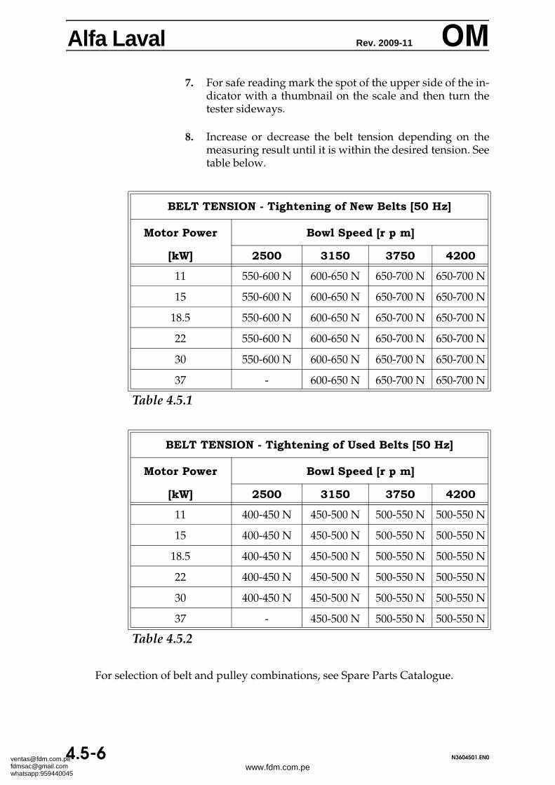
ATTENTION Store spare V-belts in a dry and cool place.Never roll up the V-belts. Sharp bends will damage them.
Before installing new belts, check the pulleys for wear, using,if necessary, a profile and groove gauge.
When installing new belts, rotate the belt drive a few turns be-fore measuring the belt tension, repeating this procedure untilthe belt tension is correct. For the belt tension values, refer tosection 4.5.
Check the belt tension after 0.5-4 hours of full load opera-tion and then every 4000 hours, referring to section 4.5 for thebelt tension values, and not forgetting to rotate the belt driveevery time before measuring the belt tension.
All types of V-belts used for the main drive should normallybe exchanged every 16000 hours.
Alfa Laval Rev. 1997-11 OM3.7 Variable Frequency Drive (VFD)
Refer to section 5 ’Supplementary Documentation’ for the spe-cific descriptions of the electrical motor and the frequency in-verter and follow the given instructions for service and main-tenance.
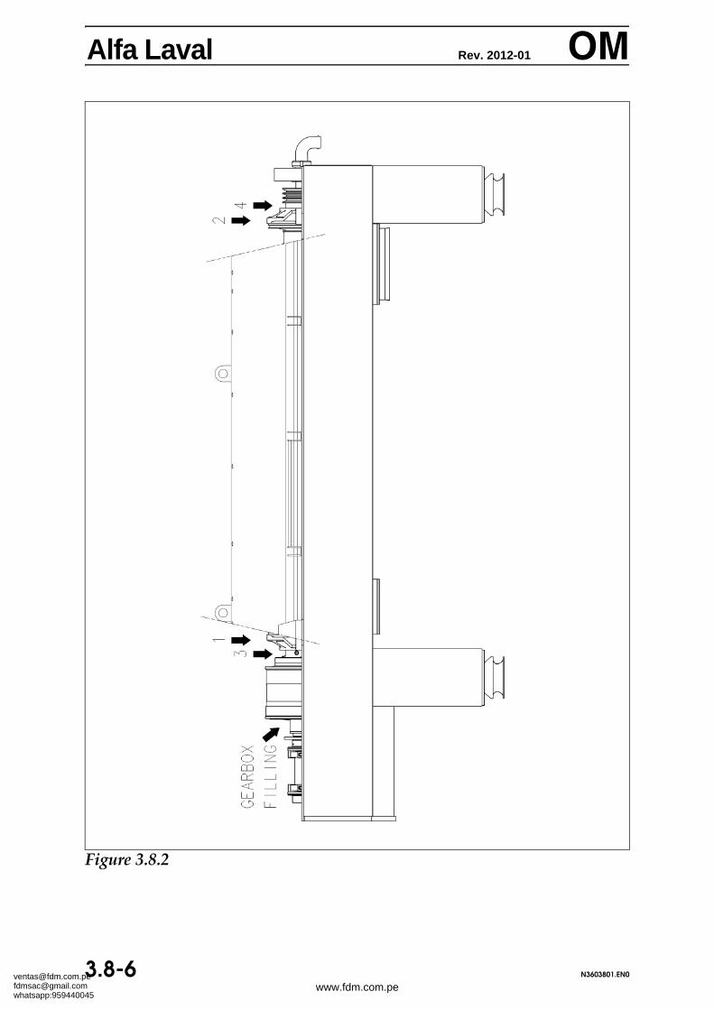
Figure 3.8.11. Main Bearing, Large End 2. Main Bearing, Smal End3. Conveyor Bearing, Large End 4. Conveyor Bearing, Small End5. Discharge opening, Large End 6. Discharge Opening, Small End
(Fig. 3.8.1 shows where the lubricating nipples are located)
GeneralThe lubricants for the decanter must always be stored in a cool, dry, in-door area, and be protected from sunlight. Lubricant properties are verysensitive to contamination and lubricants must never be stored in opencontainers. It is strongly recommended to use lubrication grease suppliedin 400 g (14 ounce) cartridges. If larger containers are used, it is requiredto be very careful, avoid any contamination and always keep the contain-ers completely closed. Lubricant properties will change during storageand the recommended maximum shelf life from the date of filling of thelubricant container is 2 years for grease and 10 years for oil.
ATTENTION The lubrication kit supplied with decanter contains two grease gunslabelled with grease type, one for the main bearings and one for theconveyor bearings. Be very careful not to mix the grease types whenlubricating the bearings or filling the grease guns. Use of wronggrease in the bearings may result in bearing failure.
The grease gun included in the standard decanter delivery will give1.5 g (0.05 oz) in each stroke. For part number: see list of tools inSpare Parts catalogue.
3.8.1 Lubrication of Main Bearings(Nipples 1 and 2 in Fig. 3.8.1)
The main bearings shall always be lubricated while the decanter is run-ning. The optimal lubrication result is obtained if the decanter is lubricat-ed while running at low speed such as during stopping of the decanter ortowards the end of a low speed CIP cycle. Lubrication at low speed shallbe used whenever possible.
For decanters operating under extreme temperature conditions and withbearing temperatures constantly above 70°C (160°F), the time interval be-tween each lubrication shall be shortened to 150 hours.
The standard lubrication interval and lubricant quantity is:
Lubrication time interval: 300 operating hoursLubricant quantity: 9 g (0.32 oz) - 6 strokes with std. grease gun
Lubricate bearings in both ends with the above, specified quantity.
Alfa Laval Rev. 2012-01 OMIt is possible to use shorter time intervals, but if a shorter time interval isused, the quantity of grease shall always be reduced with the same factoras the time interval.
Example: If the quantity of grease specified for 300 hours is X grams,and the time interval between lubrication is 24 hours therequired grease quantity is:
Note: If the standard lubrication time interval is shortened due to extremetemperature conditions, the shortened interval shall be used in the abovecalculation.
The grease quantity and the specified lubrication interval must never beexceeded. Exceeding the specified quantity will cause over-greasing andrisk of high bearing temperatures. Exceeding the time interval will lead toinsufficient lubrication of the bearings.
Temperature alarm limitsThe bearings can withstand a temperature of 120°C / 274°F. For decanterswhere the bearing temperature is measured with a PT100 sensor directlyon the bearing outer race, the temperature limits are:
Warning limit: 110°C / 256°F
Stop limit: 120°C / 274°F
For bearing temperatures measured on the surface of the bearing hous-ings, the temperature limits shall be reduced with approximately 10°C(18°F).
It is always important to ensure that PT100 sensors are properly fitted andthe tip of the sensor is in good contact with the bearing outer race.
Alfa Laval Rev. 2012-01 OMTemperature peaksWhen a bearing is lubricated it is normal that there is a temperature peakjust after lubrication. The temperature peaks are caused by the heat gen-erated, when grease is pushed away from the rolling elements. The tem-perature peaks are not critical, unless the bearing temperature exceeds thetemperature limits or does not start to decrease to a normal level after 2-4hours. If the temperature does not decrease it can be a sign of either bear-ing contamination or hardened grease inside the bearing. Frequent greas-ing with smaller quantities will normally lead to smaller temperaturepeaks and is therefore recommended, if there are problems with high tem-perature peaks.
If there is a suspicion that a bearing has hardened or contaminated grease,the recommended procedure is to dismantle and clean the bearing com-pletely or change it. Grease should not be tried to be pushed out by add-ing large amounts of new grease or blowing with compressed air.
First start of a decanter – running inWhen a decanter is received from the factory the bearing is filled withgrease. This is to protect the bearing against contamination and dryingout during transport and storage. It is therefore advised not to the start thedecanter at full speed, but first do a low speed rotation of the decanter. Ifthe decanter is driven with a frequency inverter, this can be obtained byrunning the decanter 15-20 minutes at the speed for low speed CIP or runa low speed CIP cycle without feed or water. If the decanter does not havea frequency inverter, it is advised to do 5 repeated starts where the decant-er is stopped when it has reached a speed of approximately 500 r.p.m.
Automatic lubrication system (Optional)The decanter can be equipped with an automatic lubrication system forthe main bearings. The pumping time and the time interval between lu-brication are controlled with a timer.
*) The pumping time is based on a pump delivering 6 grams per hour ateach outlet at continuous pumping. If the lubrication pump is calibratedto deliver a different amount per hour, the pumping time shall be adjust-ed in a proportional manner in order to obtain the same quantity of greaseas obtained with the above settings.
The timer settings shall be:
Time interval between lubrication: 6 hoursLubricant quantity at each lubrication: 0.2 grams (0.008 ounce)
Alfa Laval Rev. 2012-01 OM3.8.2 Lubrication of Conveyor Bearings
(Nipples 3 and 4 in Fig. 3.8.1)
At lubrication of conveyor bearings, the decanter must be stopped and themain power must be properly disconnected according to the safety in-structions.
For decanters operating with feed temperatures above 90°C (200°F), thelubrication interval shall be shortened to 500 hours.
If the decanter is cleaned with low speed CIP, it is recommended to lubri-cate the conveyor bearings after the low speed. The quantity of greaseshall be reduced according to the number of operating hours betweeneach low speed CIP.
Example: If the quantity of grease specified for 1000 hours is Xgrams, and the time interval between lubrication is 40 op-erating hours, the required grease quantity is
3.8.2.1 “Solid Oil” Conveyor Bearings (Optional)
The decanter can for some applications be equipped with conveyor bear-ings of the “Solid Oil” type.
The “Solid Oil” bearings are lubricated for life and are, in principle, main-tenance free, but it is recommended to now and then lubricate these bear-ings with a smaller amount of grease to protect the bearings against con-tamination from the outside. Do not use more than 1/4 of the normalgrease quantity in order not to damage the seals.
contd...
The conveyor bearings shall normally be lubricated for each 1000 hours. Note that this will coincide with the mandatory visual inspection of bowl, casing and gearbox.
Lubricant quantity, both ends: 30 g (1.06 oz) - 20 strokes with std. grease gun
Lubricate bearings in both ends with the above, specified quantity.
Alfa Laval Rev. 2012-01 OM3.8.3 Change of grease type - Compatibility of
greases
If the grease used for a bearing is changed, it must be checked that thethickener of new grease is compatible with the old grease. If they arenot compatible, the bearings and lubrication channels must be cleanedand free of old grease before the grease is changed. For main bearings itis strongly recommended to clean out even if the grease types are listedas compatible in order to get the optimum result. For conveyor bearingsit is usually enough to purge out the old grease. Lubricating with twicethe amount specified for normal lubrication will ensure this.
3.8.4 Cleaning out grease exits on decanters
It is recommended to do a cleaning of the grease exits from the bearinghousings each time the decanter is stopped for conveyor bearing lubri-cation and inspection. This will ensure that the grease exit is notblocked with old, hardened grease.
3.8.5 Grease accepted by Alfa Laval for lubricationof decanter bearings
Main- and conveyor bearing grease is SKF LGHP 2.(Alfa Laval p/n 61203671-50)
For food applications, conveyor bearing grease is Anderol FGCS-2.(Alfa Laval p/n 61203671-58)
Customers using other grease types, please consult Alfa Laval for advice.
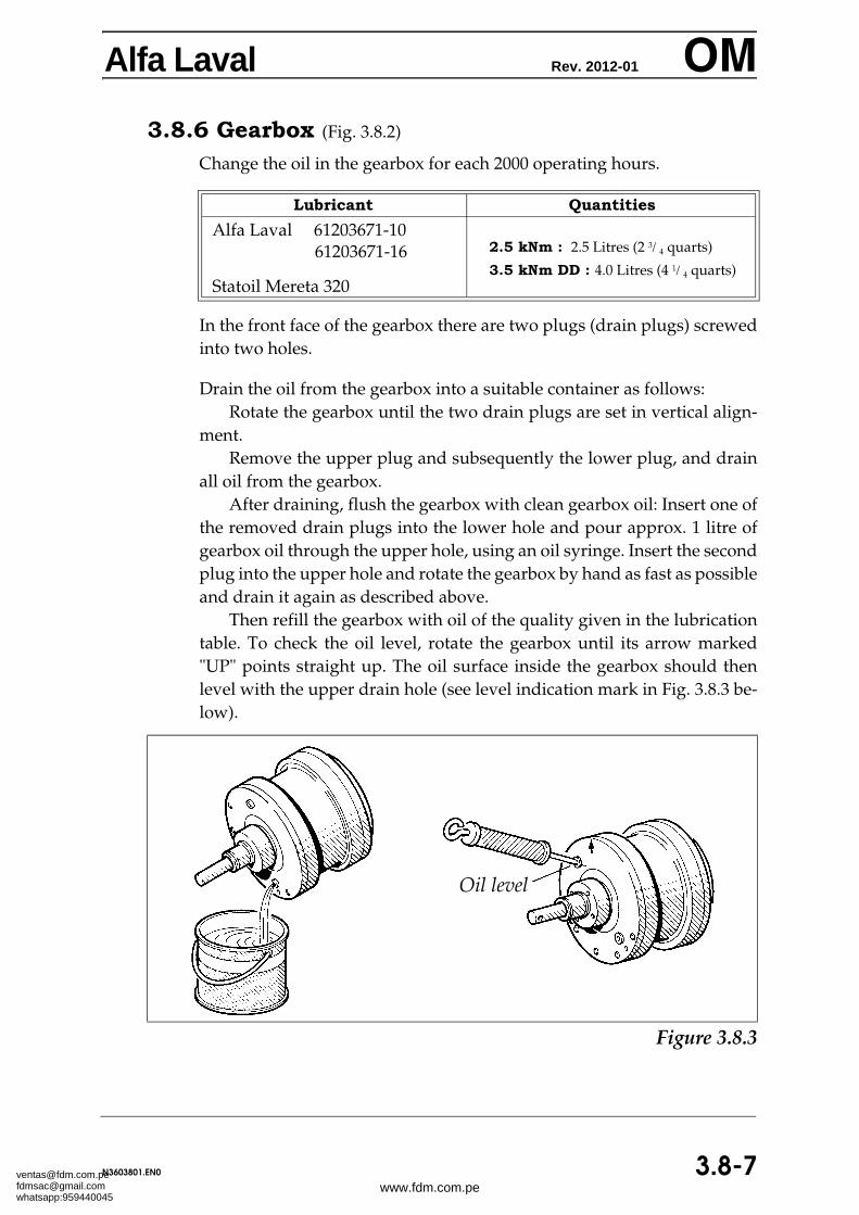
Alfa Laval Rev. 2012-01 OM3.8.6 Gearbox (Fig. 3.8.2)
Change the oil in the gearbox for each 2000 operating hours.
In the front face of the gearbox there are two plugs (drain plugs) screwedinto two holes.
Drain the oil from the gearbox into a suitable container as follows: Rotate the gearbox until the two drain plugs are set in vertical align-
ment.Remove the upper plug and subsequently the lower plug, and drain
all oil from the gearbox.After draining, flush the gearbox with clean gearbox oil: Insert one of
the removed drain plugs into the lower hole and pour approx. 1 litre ofgearbox oil through the upper hole, using an oil syringe. Insert the secondplug into the upper hole and rotate the gearbox by hand as fast as possibleand drain it again as described above.
Then refill the gearbox with oil of the quality given in the lubricationtable. To check the oil level, rotate the gearbox until its arrow marked"UP" points straight up. The oil surface inside the gearbox should thenlevel with the upper drain hole (see level indication mark in Fig. 3.8.3 be-low).
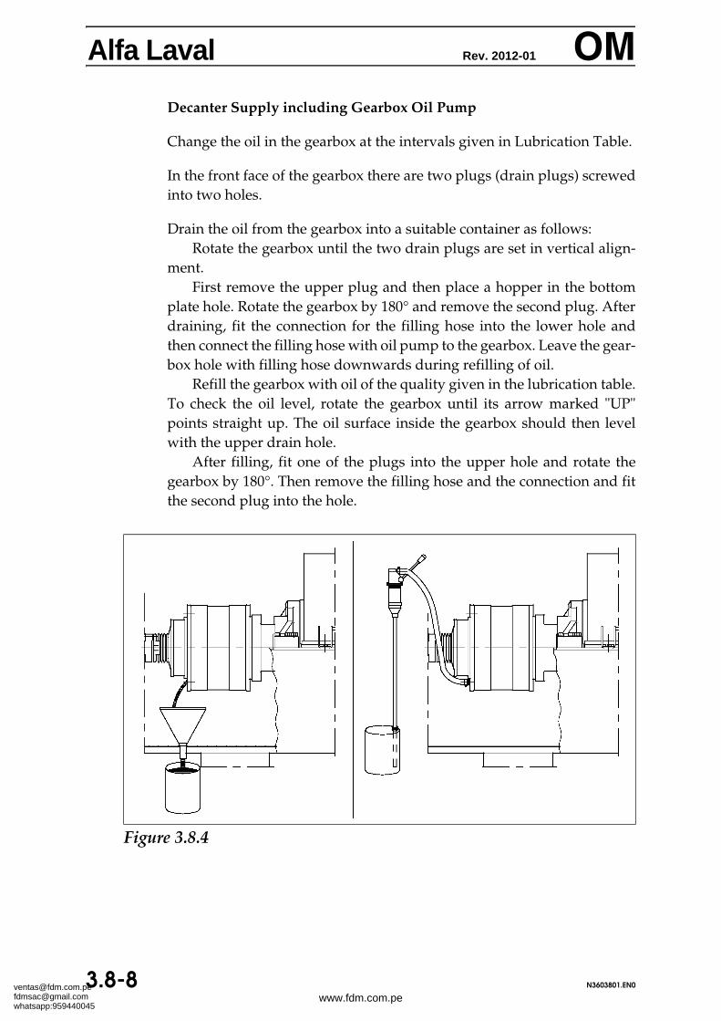
Alfa Laval Rev. 2012-01 OMDecanter Supply including Gearbox Oil Pump
Change the oil in the gearbox at the intervals given in Lubrication Table.
In the front face of the gearbox there are two plugs (drain plugs) screwedinto two holes.
Drain the oil from the gearbox into a suitable container as follows:Rotate the gearbox until the two drain plugs are set in vertical align-
ment.First remove the upper plug and then place a hopper in the bottom
plate hole. Rotate the gearbox by 180° and remove the second plug. Afterdraining, fit the connection for the filling hose into the lower hole andthen connect the filling hose with oil pump to the gearbox. Leave the gear-box hole with filling hose downwards during refilling of oil.
Refill the gearbox with oil of the quality given in the lubrication table.To check the oil level, rotate the gearbox until its arrow marked "UP"points straight up. The oil surface inside the gearbox should then levelwith the upper drain hole.
After filling, fit one of the plugs into the upper hole and rotate thegearbox by 180°. Then remove the filling hose and the connection and fitthe second plug into the hole.
Major service is replacement of all bearings and all seals while intermedi-ate (or minor) service is replacement of seals only.
It is difficult give a precise answer how often major service and interme-diate service must be done because the wear and contamination risk isboth application and installation related. Therefore it must be based on ac-tual application experience. As a rule of thumb it is recommended to carryout a major service every second year and a minor service in the interme-diate year. For some applications such as applications with high temper-atures, frequent CIP, contaminated environment and for decanters withparing disks, a major service at least once every year is recommended.
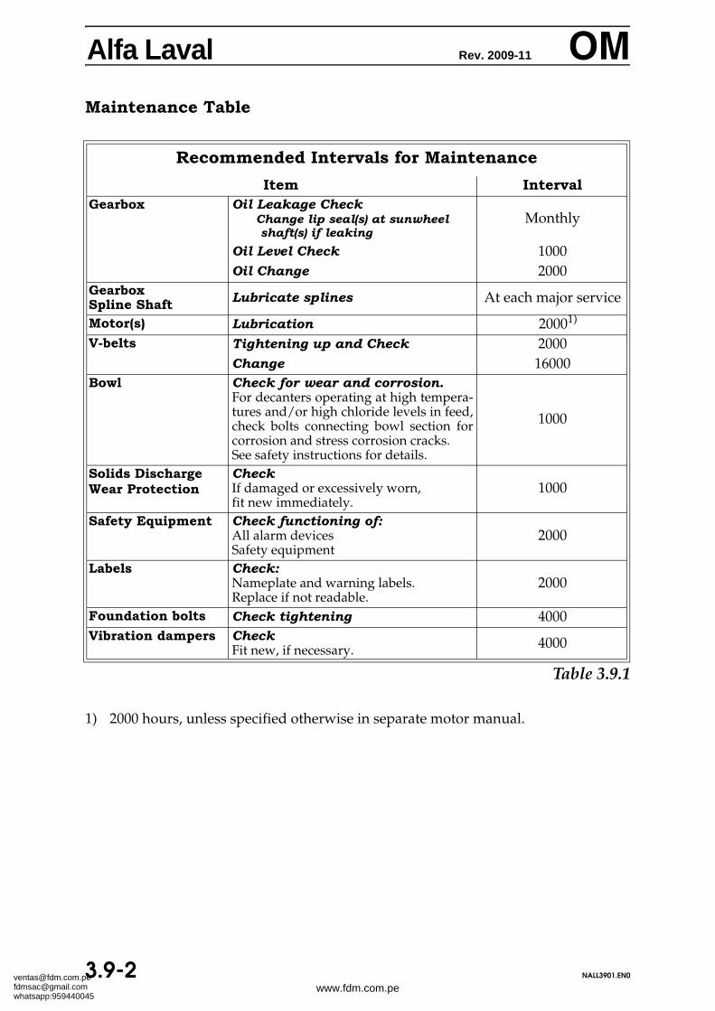
1) 2000 hours, unless specified otherwise in separate motor manual.
contd...
Recommended Intervals for Maintenance
Item IntervalGearbox Oil Leakage Check
Change lip seal(s) at sunwheelshaft(s) if leaking
Monthly
Oil Level Check 1000Oil Change 2000
GearboxSpline Shaft Lubricate splines At each major service
Motor(s) Lubrication 20001) V-belts Tightening up and Check 2000
Change 16000 Bowl Check for wear and corrosion.
For decanters operating at high tempera-tures and/or high chloride levels in feed,check bolts connecting bowl section forcorrosion and stress corrosion cracks.See safety instructions for details.
1000
Solids Discharge Wear Protection
CheckIf damaged or excessively worn,fit new immediately.
1000
Safety Equipment Check functioning of: All alarm devices Safety equipment
2000
Labels Check: Nameplate and warning labels.Replace if not readable.
2000
Foundation bolts Check tightening 4000 Vibration dampers Check
WARNING Do not make any disassembly/assembly operations on the decanterunless the main power is shut off, and the disconnected main switchis locked with a safety lock.
Replacing parts
To ensure trouble-free operation of the decanter, great caremust be taken during replacement of parts:
• Contacting and sliding surfaces, as well as O-rings andseals must be care fully cleaned.
• Always place removed parts on a clean, soft surface toavoid scratching the surfaces.
• Ensure that screws used to pull parts from each otherhave smooth ends.
O-rings, Seals, and Gaskets
Check O-rings, seals and gaskets for defects.
Check that O-ring grooves and sealing surfaces are clean.
After replacing an O-ring, check that it fills the groove com-pletely and that it is not twisted.
Ensure that seals are mounted with the open end pointing thecorrect way. See illustrations.
Always use the recommended special tools for removing,disassembling, assembling, and mounting the bowl. In case ofnegligence of this point, Alfa Laval accepts no liability for pos-sible damage to the parts.
Alfa Laval supplies a variety of special tools and accesso-ries to facilitate maintenance of the decanter. See volume SPC(Spare Parts Catalogue).
When lifting the decanter assembly use theslings specified on the dimensioned drawing.
When Lifting Minor Decanter Parts by Strapsalways use lifting straps having a load capacity of minimum1000 kg (2200 lbs).
Vibration Dampers Check regularly and change those crumbled and damperswhose rubber has swelled or cracked. Do not run the decanterif any of its dampers is defective.
Alfa Laval supplies three types of spare parts kits for the de-canter:
The intermediate kit for main bearings and conveyorbearings, respectively, contain rubber parts for the main bear-ings and the conveyor bearings.
The major kit for main bearings and conveyor bearings, re-spectively, contains parts necessary for the complete overhaulof the decanter. It includes all sealing components and bear-ings. See volume SPC (Spare Parts Cataloque).
The gearbox kit includes the lip seal for the sun wheel andthe O-ring between the splined nave and the gearbox cover.
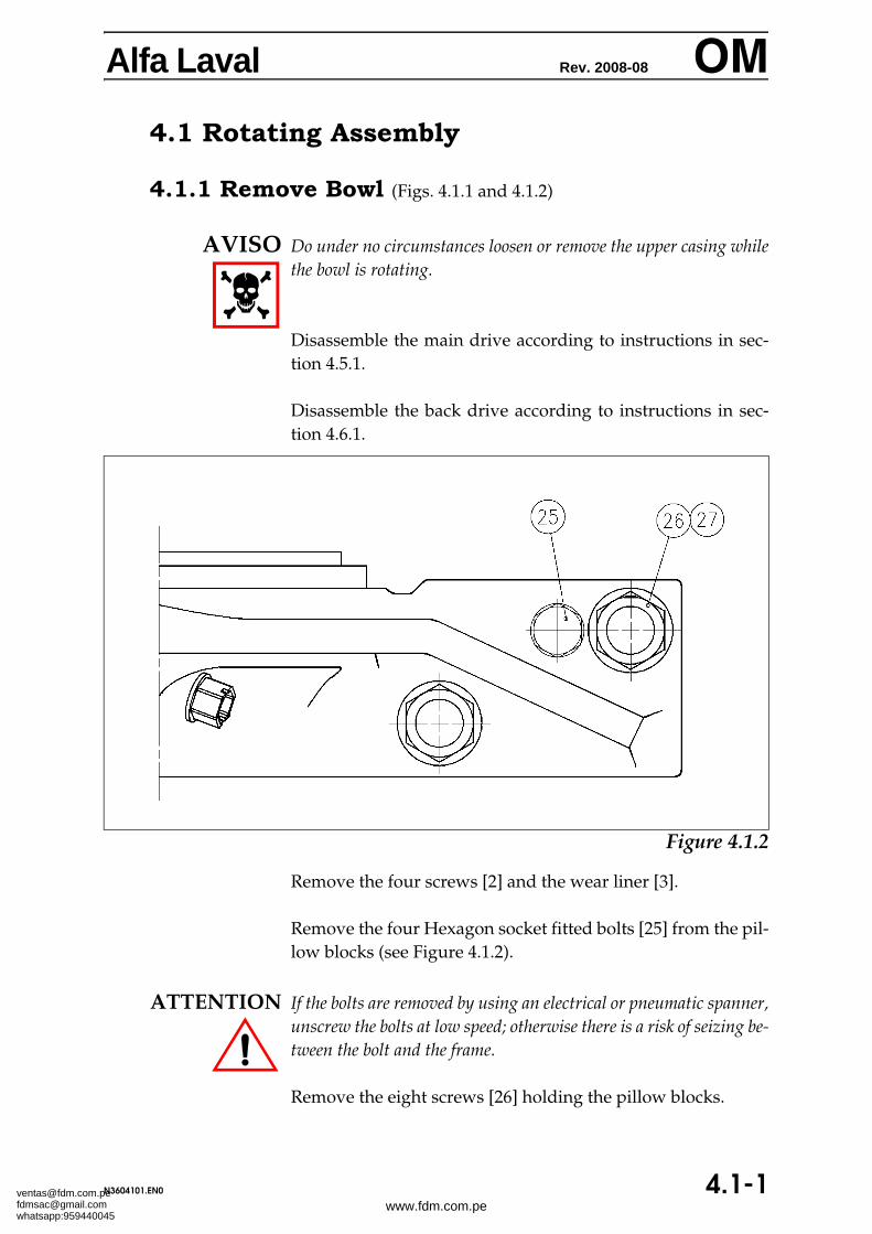
AVISO Do under no circumstances loosen or remove the upper casing whilethe bowl is rotating.
Disassemble the main drive according to instructions in sec-tion 4.5.1.
Disassemble the back drive according to instructions in sec-tion 4.6.1.
Table 4.1.1
Remove the four screws [2] and the wear liner [3].
Remove the four Hexagon socket fitted bolts [25] from the pil-low blocks (see Figure 4.1.2).
ATTENTION If the bolts are removed by using an electrical or pneumatic spanner,unscrew the bolts at low speed; otherwise there is a risk of seizing be-tween the bolt and the frame.
Remove the eight screws [26] holding the pillow blocks.
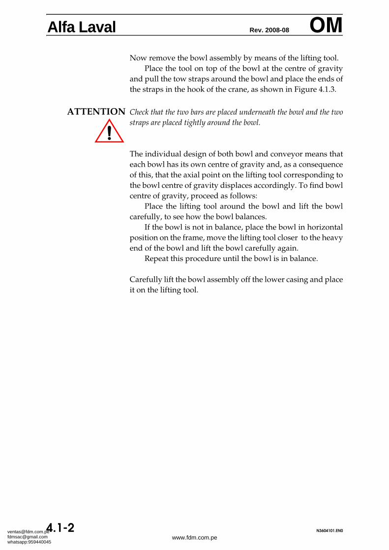
Alfa Laval Rev. 2008-08 OMNow remove the bowl assembly by means of the lifting tool.
Place the tool on top of the bowl at the centre of gravityand pull the tow straps around the bowl and place the ends ofthe straps in the hook of the crane, as shown in Figure 4.1.3.
ATTENTION Check that the two bars are placed underneath the bowl and the twostraps are placed tightly around the bowl.
The individual design of both bowl and conveyor means thateach bowl has its own centre of gravity and, as a consequenceof this, that the axial point on the lifting tool corresponding tothe bowl centre of gravity displaces accordingly. To find bowlcentre of gravity, proceed as follows:
Place the lifting tool around the bowl and lift the bowlcarefully, to see how the bowl balances.
If the bowl is not in balance, place the bowl in horizontalposition on the frame, move the lifting tool closer to the heavyend of the bowl and lift the bowl carefully again.
Repeat this procedure until the bowl is in balance.
Carefully lift the bowl assembly off the lower casing and placeit on the lifting tool.
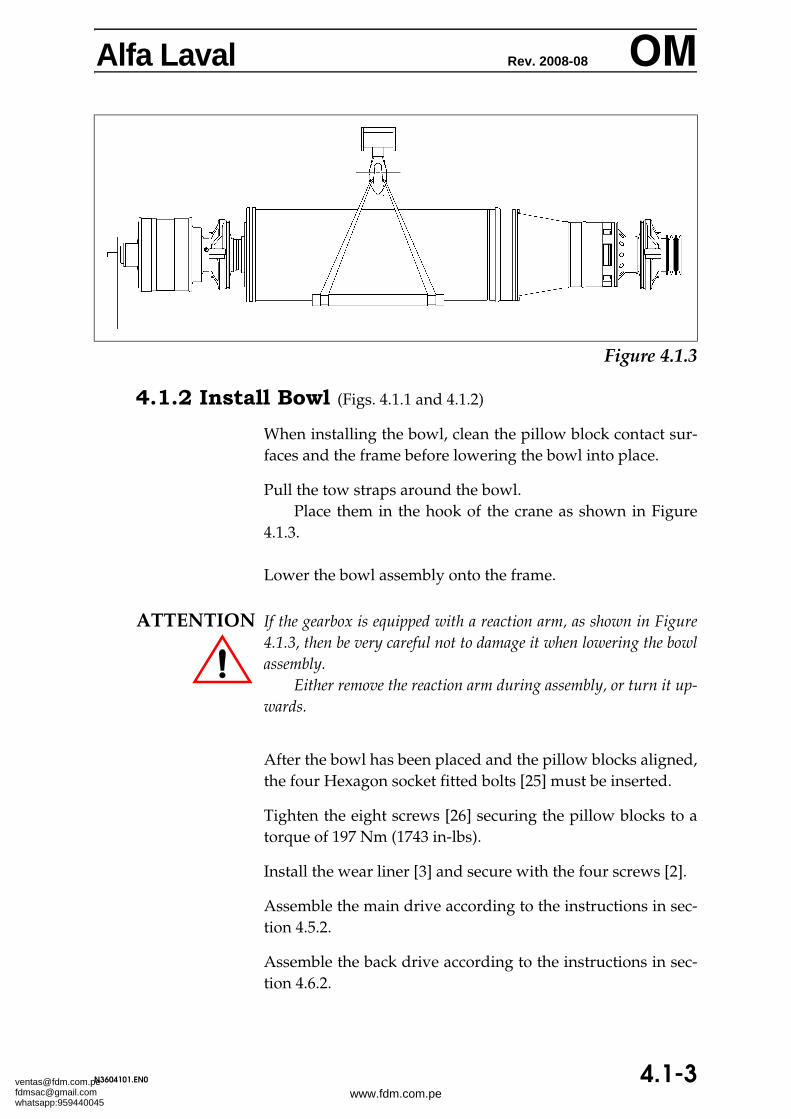
When installing the bowl, clean the pillow block contact sur-faces and the frame before lowering the bowl into place.
Pull the tow straps around the bowl.Place them in the hook of the crane as shown in Figure
4.1.3.
Lower the bowl assembly onto the frame.
ATTENTION If the gearbox is equipped with a reaction arm, as shown in Figure4.1.3, then be very careful not to damage it when lowering the bowlassembly.
Either remove the reaction arm during assembly, or turn it up-wards.
After the bowl has been placed and the pillow blocks aligned,the four Hexagon socket fitted bolts [25] must be inserted.
Tighten the eight screws [26] securing the pillow blocks to atorque of 197 Nm (1743 in-lbs).
Install the wear liner [3] and secure with the four screws [2].
Assemble the main drive according to the instructions in sec-tion 4.5.2.
Assemble the back drive according to the instructions in sec-tion 4.6.2.
Alfa Laval Rev. 2008-08 OM4.1.3 Remove Large End Hub (Fig. 4.1.4)
This procedure describes how to remove the large end hubwith the gearbox assembled to it. For removal of the gearboxfrom the large end hub, see section 4.1.7.
ATTENTION When removing the large end hub [1], always suspend it with a slingfrom a hoist or the like, to avoid excessive load to the needlebearing [9]. Place a sling around both sides of the pillow block.
Remove 23 of the 24 long screws [3], loosen the last one, andleave it in place until the end hub [1] is ready to be removed.
The end hub can now be jacked out: Using the three jackingscrews [4], clear it of the bowl.
Be careful not to damage the needle bearing [9].
Remove the loosened long screw [3] left in place and carefullypull out the end hub [1].
Turn the three jacking screws [4] back to their original posi-tion. They must not stick out through the large end hub con-tact surface when the hub is re-installed.
4.1.4 Install Large End Hub (Fig. 4.1.4)
This procedure describes how to install the large end hub withthe gearbox assembled to it. For assembling the gearbox to thelarge end hub, see section 4.1.8.
ATTENTION When mounting the large end hub [1], always suspend it with asling from a hoist or the like, to avoid excessive load to the needlebearing [9]. Place a sling around both sides of the pillow block.
Grease the outside of the O-rings [13], [106] and [14].Place the large end hub [1] on the bowl, being careful not
to damage the needle bearing [9].
Fit the 24 screws [3] and tighten them to a torque of 22 Nm(195 in-lbs).
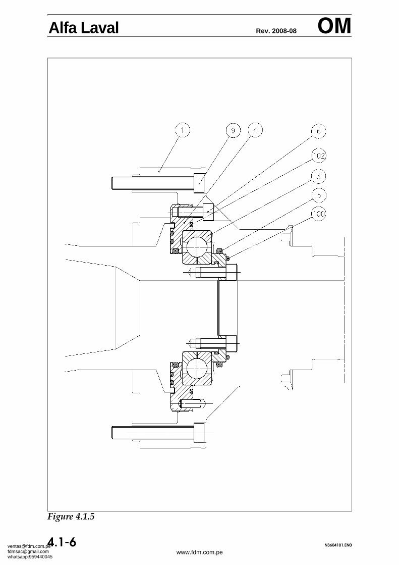
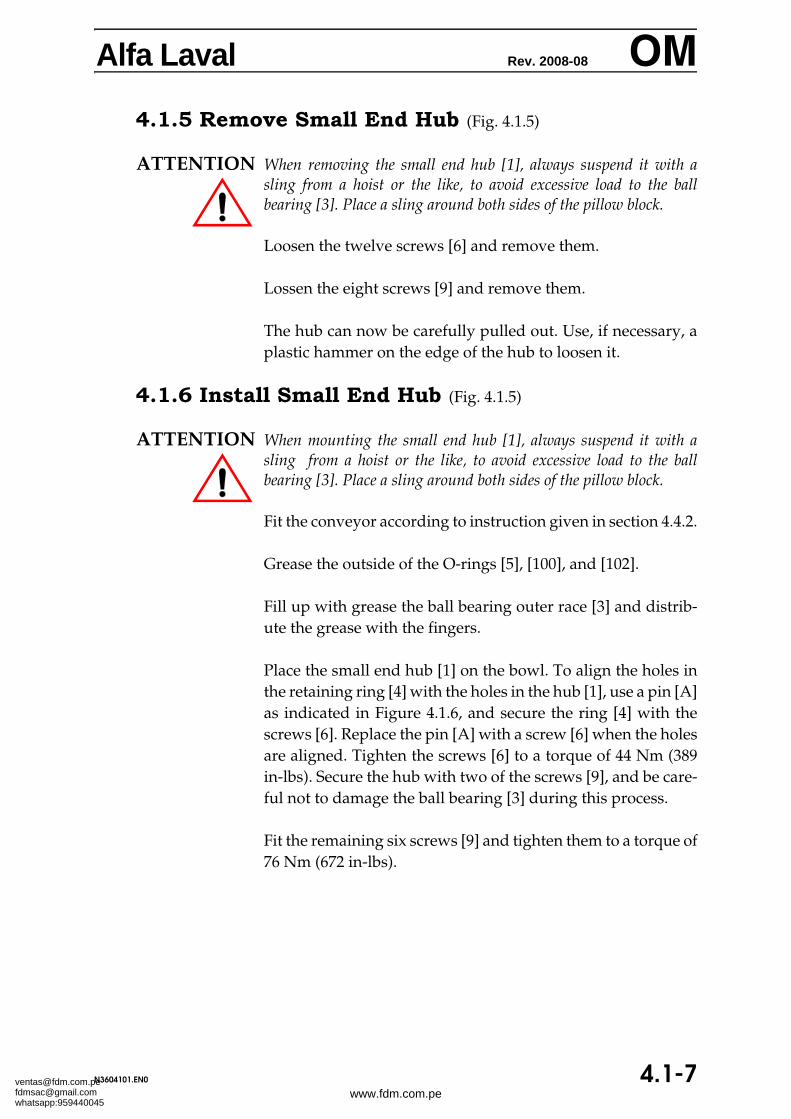
Alfa Laval Rev. 2008-08 OM4.1.5 Remove Small End Hub (Fig. 4.1.5)
ATTENTION When removing the small end hub [1], always suspend it with asling from a hoist or the like, to avoid excessive load to the ballbearing [3]. Place a sling around both sides of the pillow block.
Loosen the twelve screws [6] and remove them.
Lossen the eight screws [9] and remove them.
The hub can now be carefully pulled out. Use, if necessary, aplastic hammer on the edge of the hub to loosen it.
4.1.6 Install Small End Hub (Fig. 4.1.5)
ATTENTION When mounting the small end hub [1], always suspend it with asling from a hoist or the like, to avoid excessive load to the ballbearing [3]. Place a sling around both sides of the pillow block.
Fit the conveyor according to instruction given in section 4.4.2.
Grease the outside of the O-rings [5], [100], and [102].
Fill up with grease the ball bearing outer race [3] and distrib-ute the grease with the fingers.
Place the small end hub [1] on the bowl. To align the holes inthe retaining ring [4] with the holes in the hub [1], use a pin [A]as indicated in Figure 4.1.6, and secure the ring [4] with thescrews [6]. Replace the pin [A] with a screw [6] when the holesare aligned. Tighten the screws [6] to a torque of 44 Nm (389in-lbs). Secure the hub with two of the screws [9], and be care-ful not to damage the ball bearing [3] during this process.
Fit the remaining six screws [9] and tighten them to a torque of76 Nm (672 in-lbs).
ATTENTION When removing or installing the gearbox, always suspend it from ahoist or the like to avoid excessive load to the splined shaft. Use thelifting sling* as shown in Figure 4.1.7.
Remove the six screws (M16) connecting the gearbox to thegearbox adapter. Place the sling* as shown in Figure 4.1.7.
Suspend the gearbox from a hoist or the like and jack it
Alfa Laval Rev. 2008-08 OMout, using the three jacking screws.
Turn the jacking screws back to their original position. Theymust not stick out through the contact surface between thegearbox and the gearbox adapter when the gearbox is in-stalled again.
Carefully pull out the suspended gearbox.
The splined shaft can now be removed by hand.
4.1.8 Install Gearbox
Apply an ample amount of grease* to the splined shaft and thesplined hub in the conveyor.
Push the gearbox assembly with splined shaft carefully intoplace.
Rotate the sunwheel shaft a few turns, to make the splines en-gage.
* For P/N, see Spare Parts Catalogue, Section TOOLS AND LUBRICANTS
2.5 kNm Gearbox3.5 kNm Gearbox
Insert the six screws (M16) assembling the gearbox adapter tothe gearbox and tighten them to a torque of 197 Nm (1743in-lbs) in the sequence shown in Figure 4.1.8.
Alfa Laval Rev. 2008-08 OM4.1.9 Fit New Wear Liners (Fig. 4.1.9).
When the small end hub has been demounted, it is possible toexchange the wear liners [1]. Do not expect to reuse the oldwear liners after demounting as the material is very brittle andprobably will break.
Demounting of worn wear liners:
Disconnect the wear liner [1] with a small chisel and a ham-mer. Be careful not to damage the mating surfaces on thespokes of the hub.
Alfa Laval Rev. 2008-08 OMMounting of new wear liners:
- Clean the surface for glue residues, and thoroughly cleanall surfaces that are to be glued, on spokes and wear liners[1] with acetone.
- Apply Araldite 2014 zigzag-wise on the inner side of thewear liner [1].
- The wear liner [1] is placed on the spoke and rotated backand forth until it feels as if it is floating. Then it is pushedinto place and secured with a rubber band. Be careful thatthe gap is completely filled with glue.
- Remove excess Araldite.
Hardening time: 3.5 hours at 20oC (68oF)0.5 hour at 60oC (140oF)5 min. at 100oC (212oF)
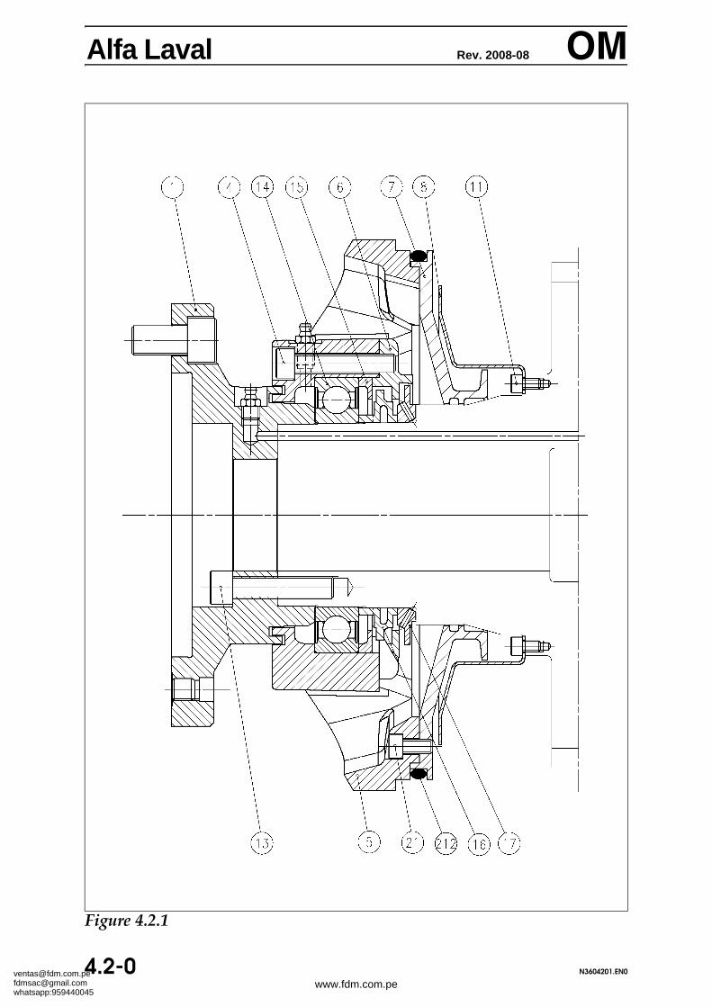
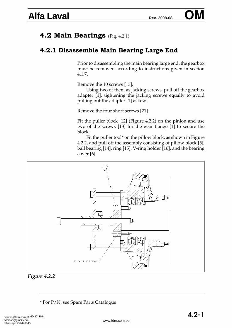
Alfa Laval Rev. 2008-08 OM4.2 Main Bearings (Fig. 4.2.1)
4.2.1 Disassemble Main Bearing Large End
Prior to disassembling the main bearing large end, the gearboxmust be removed according to instructions given in section4.1.7.
Remove the 10 screws [13].Using two of them as jacking screws, pull off the gearbox
adapter [1], tightening the jacking screws equally to avoidpulling out the adapter [1] askew.
Remove the four short screws [21].
Fit the puller block [12] (Figure 4.2.2) on the pinion and usetwo of the screws [13] for the gear flange [1] to secure theblock.
Fit the puller tool* on the pillow block, as shown in Figure4.2.2, and pull off the assembly consisting of pillow block [5],ball bearing [14], ring [15], V-ring holder [16], and the bearingcover [6].
Alfa Laval Rev. 2008-08 OMDisassemble the pillow block: Remove, in the following order,the four long screws [4], the bearing cover [6], the V-ring hold-er [16], and the ring [15].
Use a hammer and a brass mandrel to remove the ball bearing[14], taking care that the mandrel does not damage the pillowblock [5].
Remove, by hand, the guard ring [17] and the shield [7].
If necessary, remove the eight screws [11] and the splash disc[8].
Alfa Laval Rev. 2008-08 OM4.2.2 Assemble Main Bearing Large End (Fig. 4.2.1)
Fit by hand the splash disc [8] on the pinion.Insert an tighten the eight screws [11].
Fit the O-Ring [212] on the shield [7] and place the shield onthe pinion. Make sure its 'cut edge' points downwards.
Fit the guard ring [17] on the pinion, its two holes pointingoutwards.
Push the bearing cover [6] on the guard ring [17], its greasedischarge pointing downwards, and then fit the V-Ring hold-er [16] on the pinion.
Insert the ball bearing [14] into the pillow block [5] and greasethe balls.
Then fit the ring [15] and push carefully the assembly onthe pinion.
ATTENTION The ball bearing must be exchanged after disassembly as it may havebeen damaged during removal.
Insert the four long screws [4] attaching the bearing cover [6]to the pillow block [5], and the four short screws [21] securingthe shield [7].
Tighten all twelve screws.
Carefully clean the contact surfaces between the gearboxadapter [1] and the pinion.
Place the gearbox adapter [1] on the large end pinion,aligning the axial hole in the adapter and the guide pin on theend surface of the pinion.
Fit the 10 screws [13]. Tighten them to a torque of 136 Nm(1204 in-lbs), tightening them crosswise a few times to ensuretightening of all 10 screws to the correct torque.
Install the gearbox according to the instructions given in sec-tion 4.1.8.
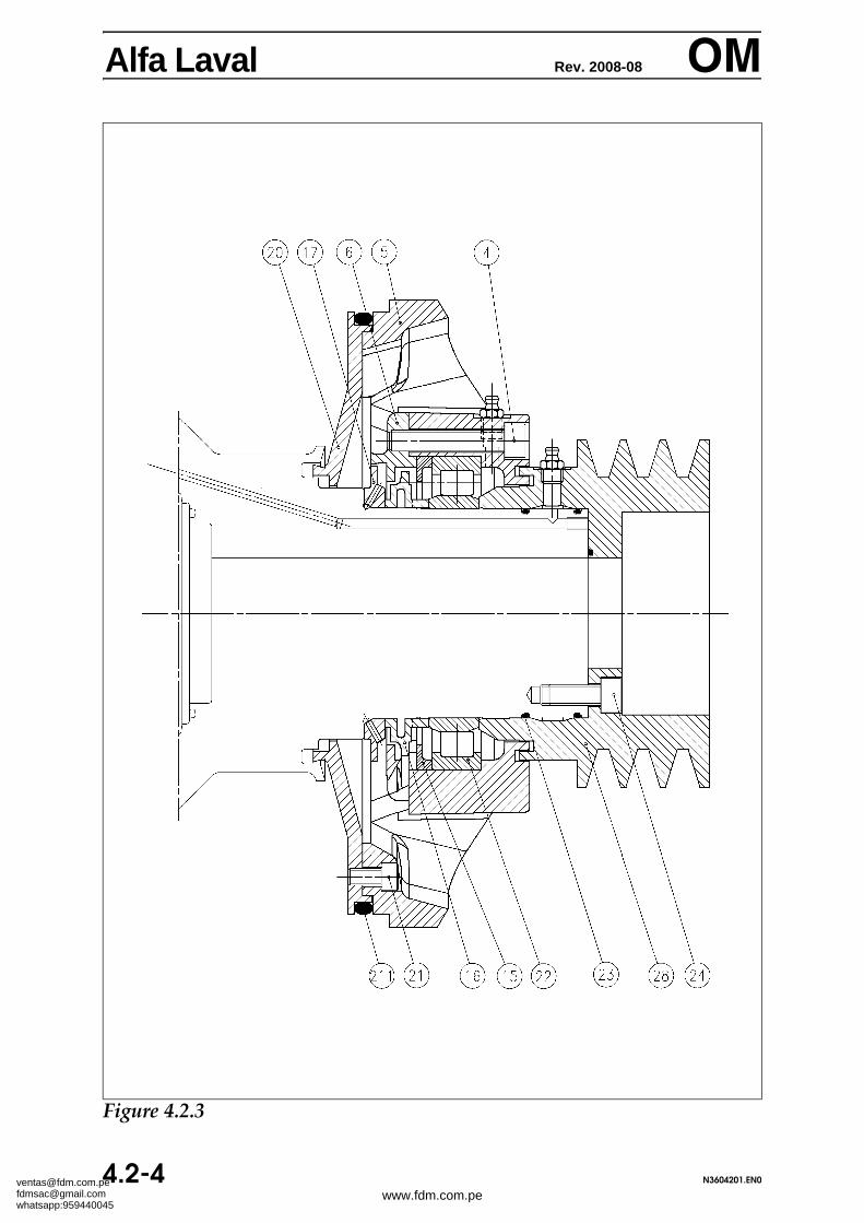
Alfa Laval Rev. 2008-08 OM4.2.3 Disassemble the Main Bearing Small End
(Fig. 4.2.3)
Remove the eight screws [24].
Using two M10 jacking screws, pull off the pulley [28], tight-ening the jacking screws equally, to avoid pulling the pulley[28] askew.
Remove the four short screws [21] and the four long screws[4].
Now remove by hand the complete bearing assembly consist-ing of pillow block [5], roller bearing outer race [22], and ring[15].
Use a hammer and a brass mandrel to remove the roller bear-ing outer race [22]. Take care that the mandrel does not dam-age the pillow block [5].
The roller bearing inner race [22] can be removed from the pin-ion by means of a standard two-armed puller* as shown inFigure 4.2.4. Two milled recesses in the V-ring holder [16] al-low space for the puller claws.
Remove, by hand and in the order mentioned, the remainingpart: V-ring holder [16], bearing cover [6], guard ring [17] andshield [20].
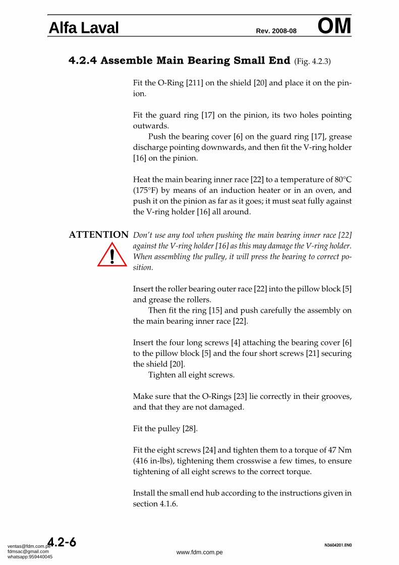
Alfa Laval Rev. 2008-08 OM4.2.4 Assemble Main Bearing Small End (Fig. 4.2.3)
Fit the O-Ring [211] on the shield [20] and place it on the pin-ion.
Fit the guard ring [17] on the pinion, its two holes pointingoutwards.
Push the bearing cover [6] on the guard ring [17], greasedischarge pointing downwards, and then fit the V-ring holder[16] on the pinion.
Heat the main bearing inner race [22] to a temperature of 80°C(175°F) by means of an induction heater or in an oven, andpush it on the pinion as far as it goes; it must seat fully againstthe V-ring holder [16] all around.
ATTENTION Don’t use any tool when pushing the main bearing inner race [22]against the V-ring holder [16] as this may damage the V-ring holder.When assembling the pulley, it will press the bearing to correct po-sition.
Insert the roller bearing outer race [22] into the pillow block [5]and grease the rollers.
Then fit the ring [15] and push carefully the assembly onthe main bearing inner race [22].
Insert the four long screws [4] attaching the bearing cover [6]to the pillow block [5] and the four short screws [21] securingthe shield [20].
Tighten all eight screws.
Make sure that the O-Rings [23] lie correctly in their grooves,and that they are not damaged.
Fit the pulley [28].
Fit the eight screws [24] and tighten them to a torque of 47 Nm(416 in-lbs), tightening them crosswise a few times, to ensuretightening of all eight screws to the correct torque.
Install the small end hub according to the instructions given insection 4.1.6.
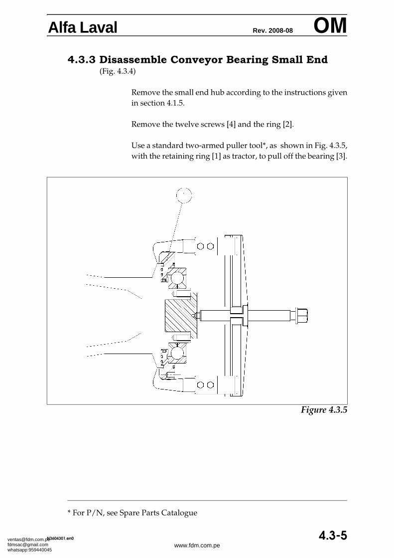
Alfa Laval Rev. 2008-08 OMRemove the snap ring ([11] in figure 4.3.1).
Insert the puller* [1] as shown in Figure 4.3.3. Tighten thenut [2] so that the conical ring [5] expands between the needlebearing outer race [9] and the hub.
Insert the screw [7] and the block [12] by using two of thescrews ([15] in Figure 4.2.1) holding the gearbox flange. Pushoff the needle bearing outer race [9] by turning the screw [7].
Alfa Laval Rev. 2008-08 OM4.3.2 Assemble Conveyor Bearing Large End
(Fig. 4.3.1)
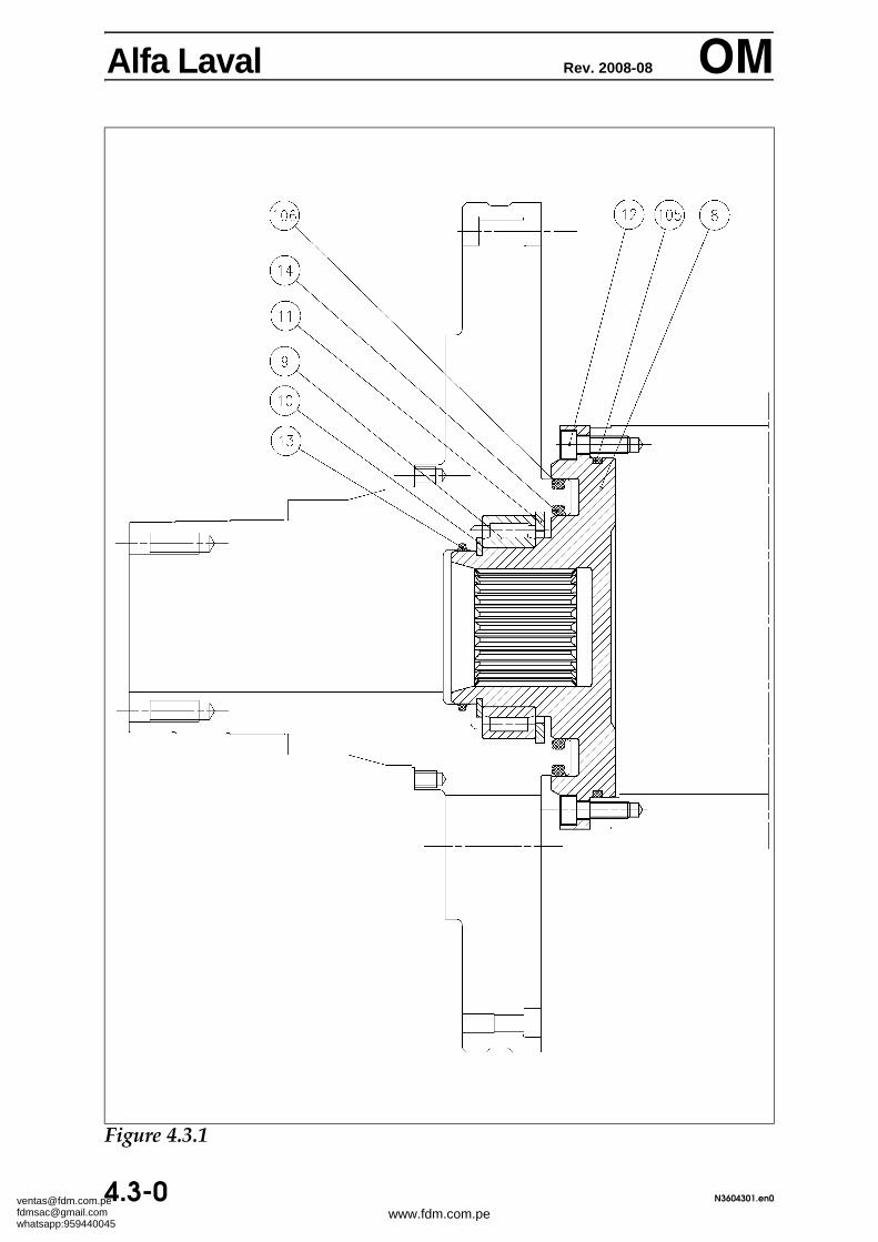
If the end flange [8] has been removed and disassembled, as-semble the parts in the following order:
Fit the O-ring [105] in the end flange [8].Insert the end flange [8]. Fit the twelve screws [12] and
tighten them to a torque of 22 Nm (195 in-lbs).
Heat the needle bearing inner race [9] by means of an induc-tion heater or in an oven to approximately 80°C (175°F) and fitit on the inner pinion; be sure it seats fully against the shoulderof the pinion. Fit the lock ring [10].
Fit the needle bearing outer race [9] onto the large end hub. Fitthe snap ring [11].
Fit the three O-rings [13], [14], and [106] and grease them.
Fill up with grease the needle bearing outer race [9] and dis-tribute the grease with the fingers.
Place the conveyor into the bowl according to the instructionsgiven in section 4.4.2.
Install the large end hub according to the instructions given insection 4.1.4.
Remove the large end hub according to instructions given insection 4.1.3.
Place the bowl (without large end hub) horizontally on twowooden trestles or the like: Attach the lifting tool* to the largeend of the conveyor as shown in Figure 4.4.1.
Connect the shackle to the hoist and fit the shackle into the lift-ing tool hole. Because of its individual design each conveyorhas its own centre of gravity. As consequence of this the axialpoint on the lifting tool corresponding to the conveyor centreof gravity is not the same for all conveyors. To find the actualconveyor centre of gravity, proceed as follows:
Fit the shackle in the lifting tool centre hole and lift theconveyor carefully, to see how the it balances.
If the conveyor is not in balance, then insert the shackleinto the next lifting tool hole nearer to the heavy end of theconveyor and lift the conveyor carefully again.
Repeat this procedure until the conveyor is in balance andmark the centre of gravity hole of the lifting tool, to facilitatefuture disassembling and assembling.
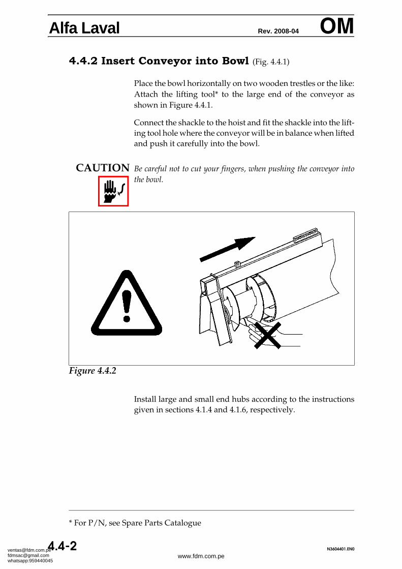
Alfa Laval Rev. 2008-04 OM4.4.2 Insert Conveyor into Bowl (Fig. 4.4.1)
Place the bowl horizontally on two wooden trestles or the like:Attach the lifting tool* to the large end of the conveyor asshown in Figure 4.4.1.
Connect the shackle to the hoist and fit the shackle into the lift-ing tool hole where the conveyor will be in balance when liftedand push it carefully into the bowl.
CAUTION Be careful not to cut your fingers, when pushing the conveyor intothe bowl.
Install large and small end hubs according to the instructionsgiven in sections 4.1.4 and 4.1.6, respectively.
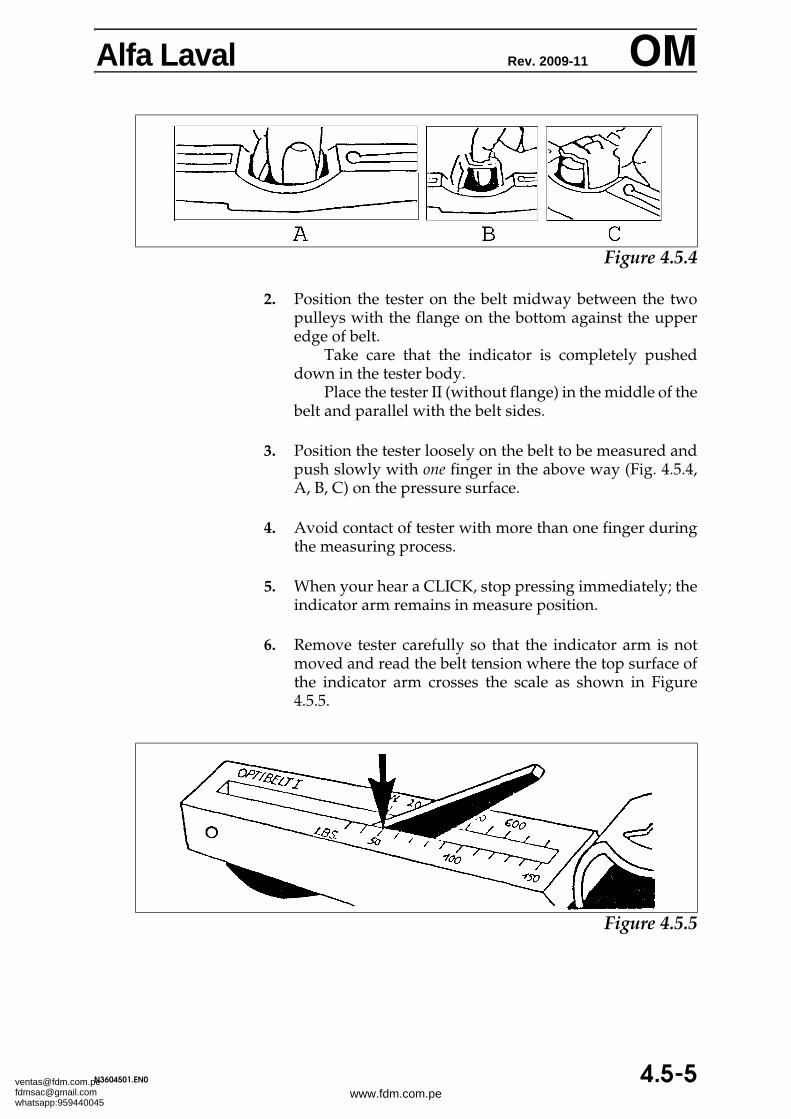
2. Position the tester on the belt midway between the twopulleys with the flange on the bottom against the upperedge of belt.
Take care that the indicator is completely pusheddown in the tester body.
Place the tester II (without flange) in the middle of thebelt and parallel with the belt sides.
3. Position the tester loosely on the belt to be measured andpush slowly with one finger in the above way (Fig. 4.5.4,A, B, C) on the pressure surface.
4. Avoid contact of tester with more than one finger duringthe measuring process.
5. When your hear a CLICK, stop pressing immediately; theindicator arm remains in measure position.
6. Remove tester carefully so that the indicator arm is notmoved and read the belt tension where the top surface ofthe indicator arm crosses the scale as shown in Figure4.5.5.
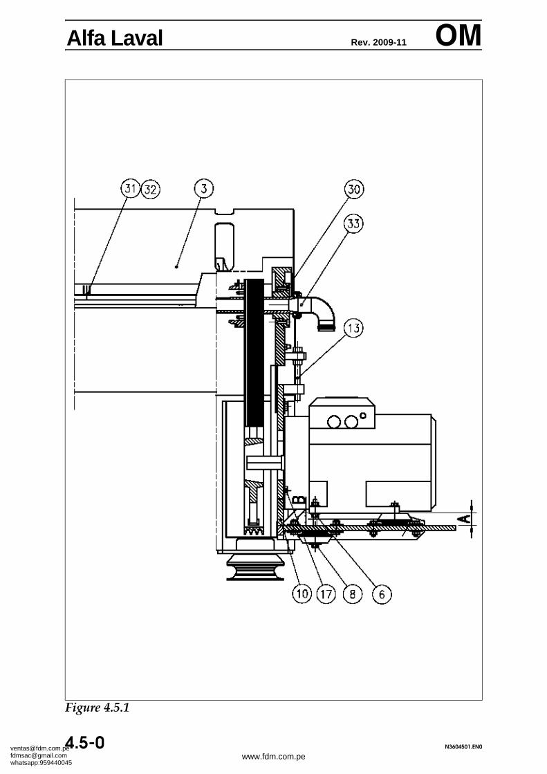
Alfa Laval Rev. 2011-06 OMInstall the coupling part [5] and engage it completely on themotor shaft. Now install the other part of the coupling [4] onthe sunwheel shaft and put the two coupling parts into en-gaged position, by means of the shaft [33], leaving an axialplay of 3-4 mm (1/8 inch) between them. Tighten the set-screws, and install and tighten the six screws [30].
Install the sensor bracket [9] and fasten with the two screws [7]and washers [8].
Install the upper casing [3] and secure with the screws andwashers [31] and [32].
Alfa Laval Rev. 2006-11 OMSupplementaryTechnical Details
Wear liner assembly (figure 1)
1 Rough-grind the hatched surface of the feed rotor to get arugged surface.
2 Degrease the grinded surfaces with Chesterton 277.
3 Apply an even layer of approx. 2-3 mm of the ready-mixed ARC 858 on both feed rotor and wear liner.
4 Turn the wear liner into place and fix it with securingplates. Mind to turn the wear liner correctly. Disperse ex-cess composite so that it fills the gap between feed rotorand wear liner.
Wear liner disassembly
I. Remove the screws in the securing plates and remove theplates.
II. Attempt to loosen the wear liner from the backside with abrass mandrel or the like. Heating to 120-130o C might benecessary.
III. After removal of the wear liner, the hatched area of thesurface is cleaned, as described under assembly.
OBS! Wear liners in WC are at great risk of breaking, when at-tempted removed.
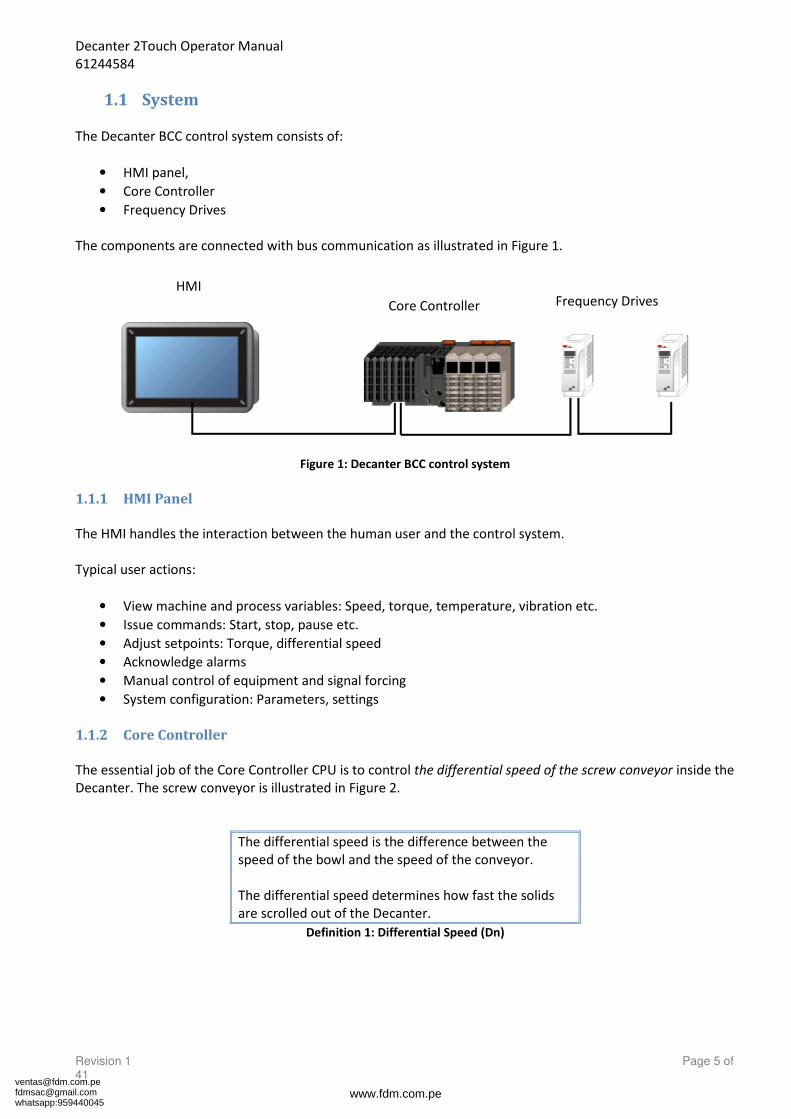
1.1 System ..................................................................................................................................................... 5
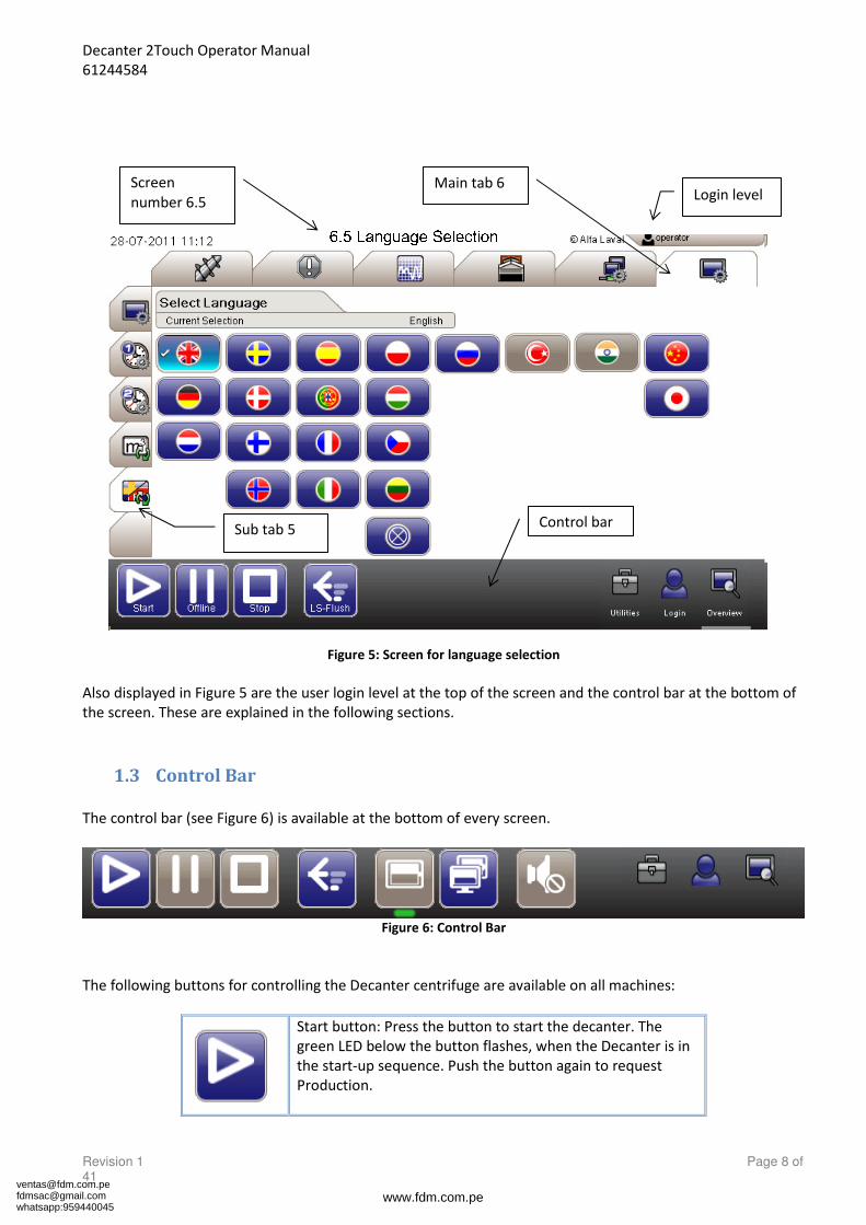
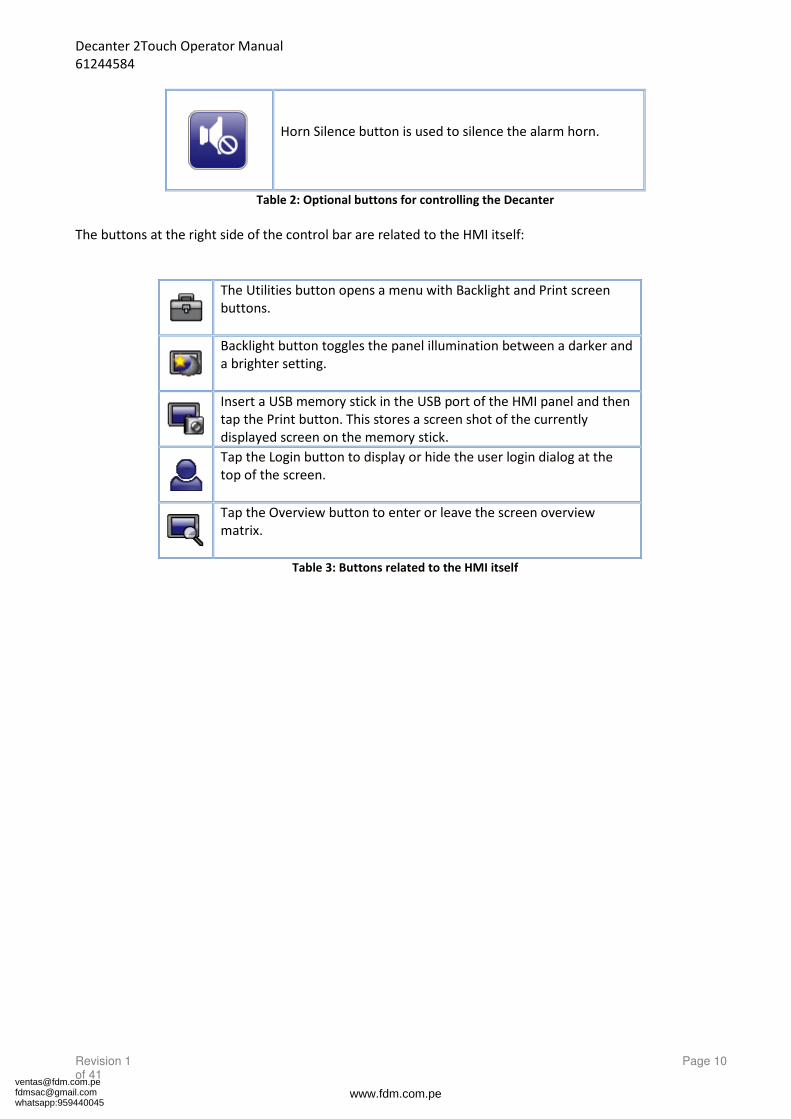
1.3 Control Bar ............................................................................................................................................... 8
1.4 User Login Dialog ................................................................................................................................... 11
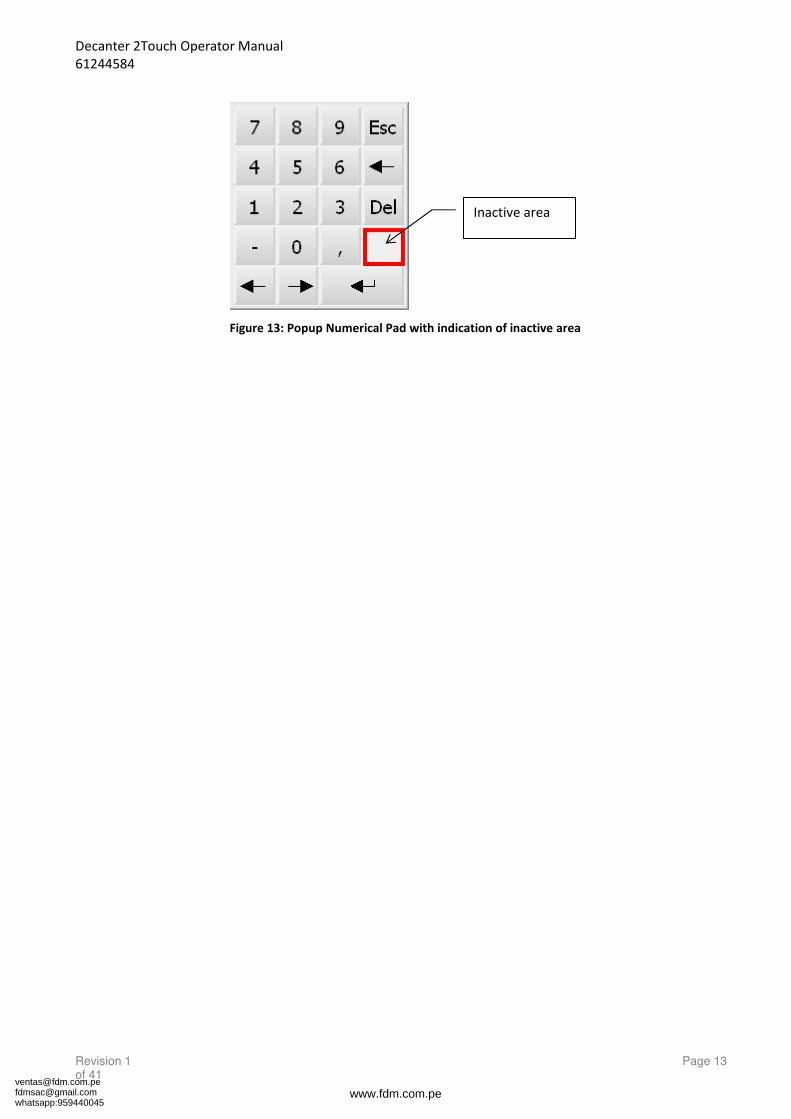
1.5 Popup Keyboard and Numerical Pad ..................................................................................................... 12
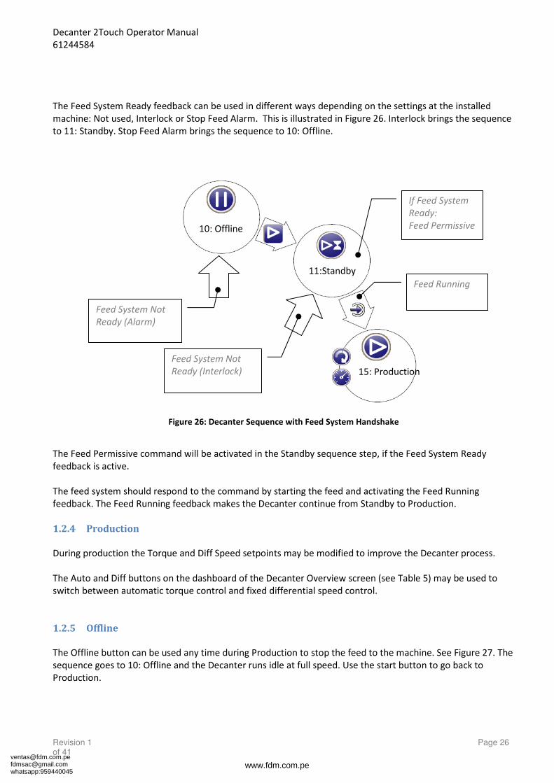
1.2 Main Sequence ...................................................................................................................................... 24
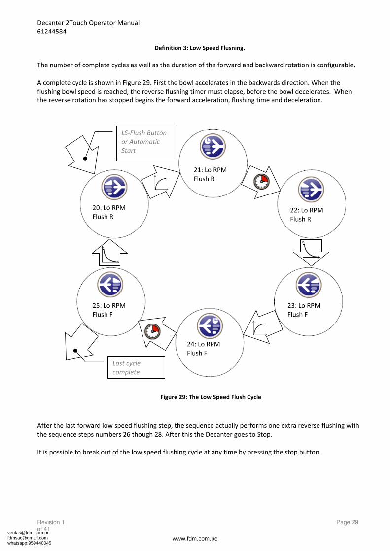
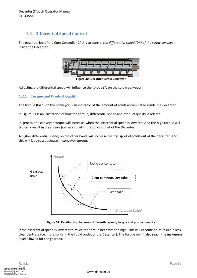
1.3 Differential Speed Control ..................................................................................................................... 30
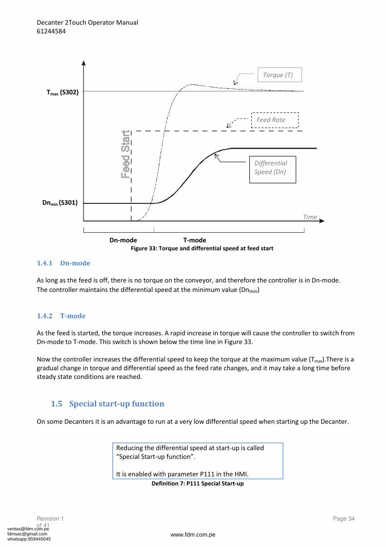
1.4 Example: Automatic control at feed start ............................................................................................. 33
1.5 Special start-up function ....................................................................................................................... 34