Shell-and-tube dry expansion evaporators Alfa Laval DH A new shell-and-tube dry expansion evaporator for positive temperature applications ERC00680EN 1512 Alfa Laval in brief Alfa Laval is a leading global provider of specialized products and engi- neered solutions. Our equipment, systems and services are dedicated to helping customers to optimize the perfor- mance of their processes. Time and time again. We help our customers to heat, cool, separate and transport prod- ucts such as oil, water, chemicals, beverages, foodstuffs, starch and pharmaceuticals. Our worldwide organization works closely with customers in almost 100 countries to help them stay ahead. How to contact Alfa Laval Up-to-date Alfa Laval contact details for all countries are always available on our website at www.alfalaval.com Alfa Laval reserves the right to change specifications without prior notification.
Transcript
Shell-and-tube dry expansion evaporators Alfa Laval DH
A new shell-and-tube dry expansion evaporator for positive temperature applications
ERC00680EN 1512
Alfa Laval in brief
Alfa Laval is a leading global provider of specialized products and engi-neered solutions. Our equipment, systems andservices are dedicated to helping customers to optimize the perfor-mance of their processes. Time and time again. We help our customers to heat, cool, separate and transport prod-ucts such as oil, water, chemicals, beverages, foodstuffs, starch and pharmaceuticals. Our worldwide organization works closely with customers in almost 100 countries to help them stay ahead.
How to contact Alfa Laval
Up-to-date Alfa Laval contact details for all countries are always available on our website at www.alfalaval.com
Alfa Laval reserves the right to change specifications without prior notification.
1
Performance and features 1
Design data 1
PED (CE) approval 1
Denomination 2
Materials 2
Capacity and maximum allowable water flow chart 3
General dimensions 4
Shell diameter = 141 mm 5
Shell diameter = 168 mm 6
Shell diameter = 194 mm 7
Shell diameter = 219 mm 8
Shell diameter = 273 mm 9
Shell diameter = 324 mm 10
Shell diameter = 406 mm 11
Shell diameter = 457 mm 12
Shell diameter = 508 mm 13
Refrigerant connections 14
Flange connections 14
Welding connections 15
Rotalock connections 15
Brine connections 16
Threaded water connections 16
Victaulic flexible joint water connections 17
Vic-Flange water connections 18
Welded flange water connections 18
Options 19
Design data
Table of contents Performance and featuresThe Alfa Laval’s DH design has been optimized for R407F, R407C and R410A refrigerants but it can also work with R134a as well as other HFC , HFO refrigerants ( like R1234ze) and also natural refrigerants like R290 and R1270. It has beeen developed for commercial and industrial refrigeration cooling with positive evaporation temperature, tipically in a range of 0°C/10°C.
With its innovative patented refrigerant distributor and new optimized plastic baffles designed to improve the brine side heat transfer performances, Alfa Laval’s new DH shell-and-tube evaporator series guarantees maximum efficiency, low cost and compactness. Alfa Laval’s DH exchange tubes has a specific inner grooved pattern to maximize the heat transfer coefficient and to limit the pressure drop negative effects.
DH special version with Tmin = -40°C is available on demand. Please refer to your Alfa Laval local sales organization to have more information.
32
MaterialsThe materials used for standard version of DH are the following:
Tubes: copper Baffles: plastic Tubes sheet: carbon steelShell and water connections: carbon steelHeader and refrigerant connections: carbon steel
Different materials are available on request, according to the following list. Please contact your Alfa Laval local sales organization for further details.
Tubes: copper-nickel 90/10 alloy, stainless steel AISI 316L, carbon steelBaffles: carbon steel, stainless steel AISI 316LTubes sheet: stainless steel AISI316 LShell and water connections: stainless steel AISI316 L
Number of circuits 1 = 1 circuits2 = 2 circuits3 = 3 circuits4 = 4 circuits
Product line
DH 322- 3 H
Model identification
number1, 2, 3, 4
Baffles span_ = standardH = short distanceX = shorter distance
In the description there can be also a letter indicating the water connections orientation. Three available orientation for water connections: top (standard), left (L) and right (R).
Design data
Capacity and maximum allowable water flow chartThe capacities in the chart below are calculated with the following working conditions:
Q_nom [kW] DP_nom [kP] W_nom [m3/h] W_max [m3/h]
DH_-141 18.6 16 4 6.3
DH_-142 28.2 29 6 7.5
DH_-143 35.1 27 6 10
DH_-144 47 41 8 11
DH_-161 55.4 34 9.5 11.5
DH_-162 62.7 35 10.8 14.5
DH_-163 78.6 40 13.5 19
DH_-164 93.2 44 16 22
DH_-191 124.4 40 21.1 35
DH_-192 143.6 48 24.7 35
DH_-193 163.4 37 27.8 35
DH_-211 202.9 35 34.6 55
DH_-212 236.6 41 40.4 55
DH_-271 323.2 44 55.1 80
DH_-272 366 31 62.2 80
DH_-273 401.4 41 68.3 80
DH_-321 445.8 47 76.1 110
DH_-322 507.4 40 86.8 110
DH_-323 572.4 54 98 110
DH_-401 675.2 62 115 180
DH_-402 794.2 57 135.5 180
DH_-403 938.6 81 159.5 180
DH_-404 1019.4 104 173.4 200
DH_-451 1132 67 192.5 240
DH_-452 1259 81 216.8 240
DH_-501 1383.9 91 238.5 300
DH_-502 1562 107 269.4 320
Refrigerant = R407CBrine = WaterT_in_brine = 12°C
SC: subcooling SH: superheatingQ_nom: Nominal cooling capacityDP_nom: Nominal water pressure dropW_nom: Nominal water flowW_max: Maximum allowable water flow
NOTE: The maximum allowable flow for version with reduced distance of baffles ( H and X versions ) are different from the one in chart above. Please make reference to shell and tube thermal selection software for maximum admittable flow of H and X versions.
DH standard version is ‘not extractable tube bundle’ one. This means that the tube bundle is welded to the shell so the copper tubes can’t be removed from it.
DH is available in ‘extractable tube bundle’ version starting from shell diameter 168 mm. All models with shell diameter = 141 mm are not available in extractable version.
VOL TUBE SIDE [l] 141.3 141.4 141.3 165.8 165.8 165.7
CAT TUBE SIDE - IV IV IV IV IV IV
VOL SHELL SIDE [l] 378.7 378.7 378.7 348.5 348.5 348.5
CAT SHELL SIDE - art 3.3 art 3.3 art 3.3 art 3.3 art 3.3 art 3.3
1514
Refrigerant connections
Refrigerant connections Welding connections
Flange connections
Rotalock connections
The connection between the evaporator and the refrigerant circuit is made, depending on the evaporator size, with flange connections, welding connections or Rotalock connections.
TypeA B C D d
NameTube Connection
[mm] [mm] [mm] [mm] [mm] ODS [mm] ODS [inch] Material ID [mm]
A
20 60 55 75 M10 FC-A35 35 1 3/8" Copper 35.3
20 60 55 75 M10 FC-A42 42 1 5/8" Copper 42.4
20 60 55 75 M10 FC-A54 54 2 1/8" Copper 54.4
B20 70 70 90 M10 FC-B54 54 2 1/8" Copper 54.4
20 70 70 90 M10 FC-B67 66.7 2 5/8" Copper 67.2
C 20 70 90 110 M12 FC-C80 80 3 1/8" Copper 80.6
TypeA B
NameConnection
[mm] [mm] ODS [mm] ID [mm] OD [mm]
A
20 60 WA22 22 23 26.7
20 60 WA35 35 35.3 42.4
20 60 WA42 42 42 48.3
20 60 WA54 54 54.5 60.3
TypeA B C
RT NameConnection
[mm] [mm] [mm] ODS [mm] ODS [inch] ID [mm]
A 20 80 30 1" - 14UNF RA16 16 5/8" 16.3
B 20 80 36 1 1/4" - 12UNF RB22 22 7/8" 22.5
C20 80 50 1 3/4" - 12UNF RC28 28 - 28.3
20 80 50 1 3/4" - 12UNF RC35 35 1 3/8" 35.3
Refrigerant connections
1716
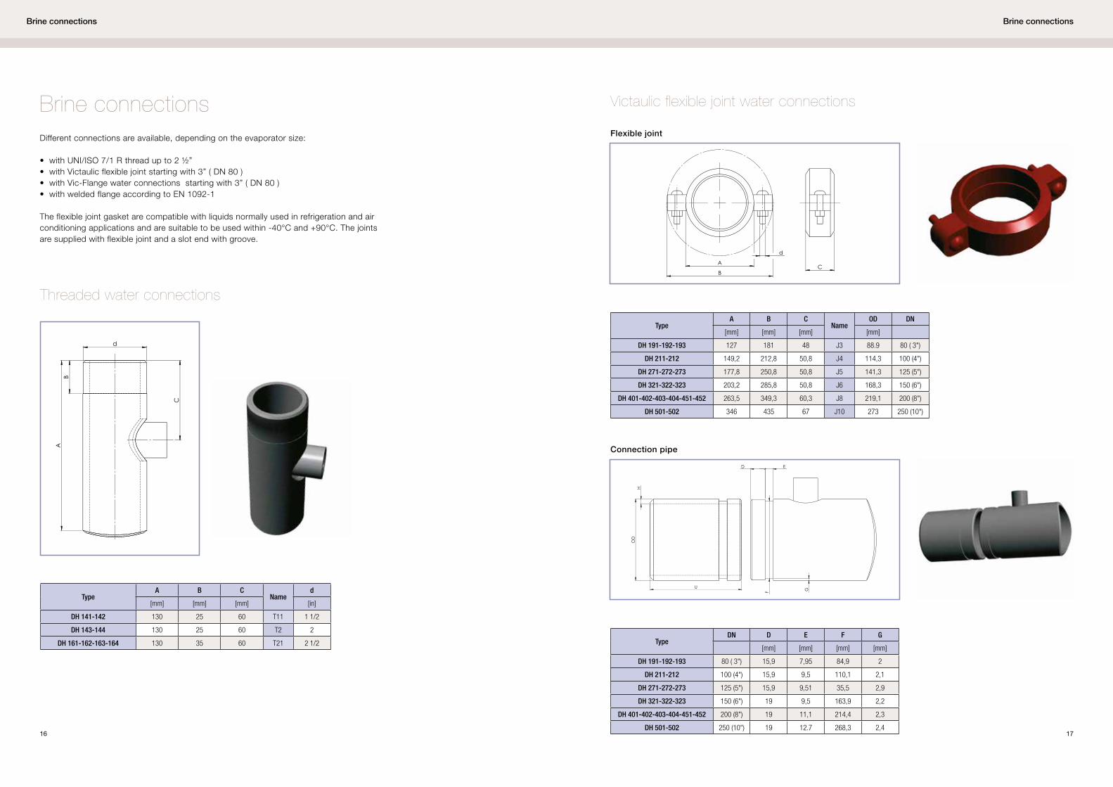
Brine connections
Brine connections Victaulic flexible joint water connections
Threaded water connections
Different connections are available, depending on the evaporator size:
• with UNI/ISO 7/1 R thread up to 2 ½” • with Victaulic flexible joint starting with 3” ( DN 80 ) • with Vic-Flange water connections starting with 3” ( DN 80 ) • with welded flange according to EN 1092-1
The flexible joint gasket are compatible with liquids normally used in refrigeration and air conditioning applications and are suitable to be used within -40°C and +90°C. The joints are supplied with flexible joint and a slot end with groove.
On request Vic-flanges can be supplied for water side connections. The Vic-Flange kit contains:
• Vic-Flange adapter ( see picture below ) with gasket• Carbon steel counter flange according to EN 1092-1
Only for extractable tube bundle version, ALFA LAVAL DH can also be supplied with welded flange according to EN 1092-1.
TypeDN A
[mm]
DH 141-142 40 130
DH 143-144 50 130
DH 161-162-163-164 65 130
DH 191-192-193 80 165
DH 211-212 100 165
DH 271-272-273 125 165
DH 321-322-323 150 215
DH 401-402-403-404-451-452 200 215
DH 501-502 250 265
Options The following options are available for DH evaporator:
• Vic-flanges water connections ( see ‘Brine connections’ section for more details )• Insulation ( thickness ¾” ) made of close cell elastomer layer ( glued ) to the evaporator surface with textile covering. The thickness of the insulation is 19 mm.• Welded supports ( see ‘General dimension’ section more informations )• Brackets supports: Alfa Laval DH can be equipped with supports welded to the shell (illustrated in the ‘General dimension’ section) or with universal brackets which are positioned in the installation phase and allows therefore the maximum flexibility (available up to shell diameter 406 mm). See table below for brackets dimensions . All dimensions are in mm.


![Alfa Laval Culturefuge 400 B · Alfa Laval is a trademark registered and owned by Alfa Laval Corporate AB. [Product name] is a trademark owned by Alfa Laval Corporate AB. PCHS00142EN](https://static.documents.pub/doc/80x56/5e71a377bc5a292f26773958/alfa-laval-culturefuge-400-b-alfa-laval-is-a-trademark-registered-and-owned-by-alfa.jpg)


