Alfa Laval Contherm Table Of Contents Instruction And Parts Manual Chapter Title One Safety Summary Two Warranty And Product Support Three General Description Four Serial Number Information Five Installation Six Operation Seven Maintenance Eight Troubleshooting Nine Spare Parts Information Ten Special Applications And Design Features Appendices Index
Transcript
Alfa LavalContherm
Table Of ContentsInstruction And Parts Manual
Chapter Title
One Safety SummaryTwo Warranty And Product SupportThree General DescriptionFour Serial Number InformationFive InstallationSix OperationSeven MaintenanceEight TroubleshootingNine Spare Parts InformationTen Special Applications And Design
1.1 INTRODUCTIONThe CONTHERM Scraped Surface Heat Exchanger (SSHE), manufactured by Alfa LavalContherm Inc., is a high-speed machine designed, engineered, and manufactured for safeand efficient operation when installed, operated, and maintained by knowledgeable andresponsible personnel.
Do not install, operate, or service the CONTHERM until you have read this manual andunderstand how to use the equipment. To help ensure your safety and avoid damage to theCONTHERM, we have provided safety precautions in this manual to identify potentiallydangerous or hazardous situations. While we cannot foresee every potential safety hazardthat may occur with the equipment at your facility, you can eliminate and prevent many ofthem if you follow all of the instructions provided in this manual.
Unsafe and hazardous conditions may occur if the equipment is used by improperly trainedpersonnel or without regard or knowledge of applicable safety precautions. These unsafeand hazardous conditions may cause serious personal injury and/or damage to theequipment.
1.2 SAFETY PRECAUTIONSEach safety precaution in this manual is indicated by the following symbol:
This symbol is shown whenever youneed to be aware of a potentiallyhazardous condition.
Three types of safety precautions are used in this manual, with each type determined bythe level of hazard seriousness the user is exposed to.
Danger: Immediate hazards which WILL result in severe personal injury or death.
Warning: Hazards or unsafe practices which COULD result in severe personalinjury or death.
Caution: Hazards or unsafe practices which COULD result in minor personal injuryor product or property damage.
In addition to following the safety precautions provided in this manual, use common sensewhen operating or working with the CONTHERM SSHE. In particular, be aware of problemsor hazards unique to your facility and/or operating environment. If you have any safetyconcerns that are not addressed within this manual, please notify your supervisor and/oryour local Alfa Laval Contherm Inc. or Tetra Laval representative.
2.2 WARRANTY INFORMATION ......................................................................... 2-3
2.3 PRODUCT SUPPORT SERVICES................................................................. 2-4
Chapter Two: Warranty And Product Support 2-1
Chapter 2 Warranty And Product Support
2.1 INTRODUCTIONAlfa Laval Contherm Inc. offers a warranty on the materials, workmanship and equipmentof the CONTHERM to the original purchaser of the CONTHERM. The specific details of thiswarranty are identified in Section 2.2, Warranty Information.
Alfa Laval Contherm Inc. also offers a wide range of product support services to itscustomers. These services are identified in Section 2.3, Product Support Services.
Table 2-1 shows how the warranty and product support services information in this chapterare organized:
Table 2-1. Warranty And Product Support Services Information
Section Description
2.2 WARRANTY INFORMATION
2.2.1 CONTHERM Warranty
2.2.2 Warranty Exclusions
2.2.3 Additional Warranties
2.2.4 Equipment Manufactured By Others
2.3 PRODUCT SUPPORT SERVICES
2.3.1 Returned Materials
2.3.2 Damaged Shipments
2.3.3 Service Department
2.3.4 Ordering Parts
2.3.5 Replacement Parts Policy
2.3.6 Office And Service Locations
2-2 CONTHERM Instruction And Parts Manual
2.2 WARRANTY INFORMATIONThis section describes the warranty on the materials, workmanship and equipment of theCONTHERM SSHE offered by Alfa Laval Contherm Inc. to the original purchaser of theCONTHERM. In addition to stating the specific conditions of this warranty, this sectionidentifies warranty exclusions, additional warranties, and the warranties applicable toequipment manufactured by others.
2.2.1 CONTHERM SSHE WARRANTYAlfa Laval Contherm Inc. offers the following warranty on the materials, workmanship andequipment of the CONTHERM SSHE to the original purchaser of the CONTHERM.
CONTHERM SSHE Warranty
1. Alfa Laval Contherm Inc. warrants to the original purchaser that allequipment manufactured by Alfa Laval Contherm Inc. is free fromdefects in material and workmanship.
2. Alfa Laval Contherm Inc. guarantees to repair or replace FOB (FreightOn Board) point of shipment any such equipment found to be defective,provided that written notice of the alleged defect is received by Alfa LavalContherm Inc. within 90 days from the date of shipment.
3. Alfa Laval Contherm Inc. guarantees the inner product cylinder againstexcessive wear for one (1) year from date of shipment. This guarantee isfor repair or replacement of the inner cylinder only.
2.2.2 Warranty ExclusionsThe guarantees offered within the body of the Alfa Laval Contherm Inc. Warranty areexcluded from the Warranty for damage caused by any or all of the following factors:
• Ordinary wear and tear.• Erosion or corrosion.• Misuse, abuse, or improper handling by the purchaser or any third party.
Chapter Two: Warranty And Product Support 2-3
2.2.3 Additional WarrantiesAlfa Laval Contherm Inc. makes no additional warranties, expressed or implied, whether ofmerchantability or otherwise, other than that stated in Section 2.2.1, CONTHERM SSHEWARRANTY. The manufacturer shall not be responsible for any indirect, special orconsequential damages, nor any other claims arising out of the sale or use of its equipmentbeyond the remedy stated in Section 2.2.1, CONTHERM SSHE WARRANTY.
2.2.4 Equipment Manufactured By OthersEquipment, parts or accessories manufactured by others carry the guarantee offered by theoriginal manufacturer of the equipment, parts or accessories only. Any warranties or claimswhich differ from the foregoing are unauthorized by Alfa Laval Contherm, Inc. and becomethe warranty solely of the party making them, unless specifically authorized in writing by anofficer of Alfa Laval Contherm, Inc.
Should any provision of the foregoing be held ineffective, the remaining provision shallcontinue in full force and effect.
2-4 CONTHERM Instruction And Parts Manual
2.3 PRODUCT SUPPORT SERVICESAlfa Laval Contherm Inc. offers ongoing product and technical support through a worldwidenetwork of trained, technical support personnel. These technical service representatives areavailable to assist and support you upon request, and are often utilized in the followingsituations:
• During equipment installation.• For supervising the initial start-up.• For resolving problems that occur after start-up.
2.3.1 Returned MaterialsDo not return any material or equipment until you have obtained approval from Alfa LavalContherm Inc. All materials and/or equipment returned for credit are subject to service andtransportation charges. Securely package all materials and/or equipment authorized forreturn to ensure their undamaged return.
2.3.2 Damaged ShipmentsAlfa Laval Contherm Inc. carefully packages its equipment to protect it from normalhazards that may occur during shipment. If our equipment is damaged when it arrives, theconsignee must immediately file a damage report with the carrier and forward a copy of thisclaim to the Alfa Laval Contherm Inc., Newburyport, Massachusetts, USA facility.
2.3.3 Service DepartmentAlfa Laval Contherm Inc. maintains a trained service department for servicing andsupporting its equipment. Our technical service representatives are available forassistance, supervision of start-up operations, and resolving problems occurring after start-up. We charge a per diem rate plus expenses for these services and will provide aquotation of these services to you upon request.
Within your equipment’s warranty period, all charges for service and parts attributed todefective material or workmanship will be paid by Alfa Laval Contherm Inc. However, if theservice call is necessary due to the improper operation or application of the equipment,then the service call and the necessary parts will be charged to the account of thepurchaser.
2.3.4 Ordering PartsWhen ordering parts or requesting information about service or installation, always provideus with the Model and Serial Numbers of your CONTHERM(s).
Chapter Two: Warranty And Product Support 2-5
2.3.5 Replacement Parts PolicyWhen a model is discontinued or declared obsolete, Alfa Laval Contherm Inc. will maintain,where justified, a stock of spare parts for its manufactured machines for five years. Afterfive years, Alfa Laval Contherm Inc. will provide replacement parts for the obsoleted ordiscontinued product on a custom manufacturing basis for ten more years.
Alfa Laval Contherm Inc. strongly recommends that you maintain an adequate inventory ofcritical items for any model declared obsolete. After five years, you may experience alengthy delay in receiving these items as they will then be manufactured on a custom orderbasis. Critical items for your equipment are identified in the list of recommended spareparts provided in Chapter Nine, Spare Parts Information.
Alfa Laval Contherm Inc. will help its customers obtain parts for equipment that thecompany sells but does not manufacture for a one year period after the model has beendiscontinued. After one year, you should deal directly with the original manufacturer.
2.3.6 Office And Service LocationsAlfa Laval Contherm Inc. offers its customers a worldwide network of technical sales andservice representatives. For your convenience, we encourage you to work with our localrepresentatives in your area. If you cannot locate an Alfa Laval Contherm Inc. or Alfa Lavalrepresentative in your area, please contact us directly at the following location
Alfa Laval Contherm Inc.111 Parker StreetNewburyport, MA 01950, USATelephone: (508) 465-5777Telefax: (508) 465-6006
3.12 PIN UNIT ...................................................................................................... 3-38
3.13 CONTROL PANEL ....................................................................................... 3-39
3.14 MEDIA PACKAGES (HEATING AND COOLING)......................................... 3-40
Chapter Three: General Description 3-1
Chapter 3 General Description
3.1 INTRODUCTIONThis chapter provides a general description of the CONTHERM Scraped Surface HeatExchanger (SSHE) manufactured by Alfa Laval Contherm Inc.
CONTHERM , a registered trademark of Alfa Laval Contherm Inc., is identified as the“CONTHERM” from this point on within this manual and is formatted in upper case todifferentiate it from its manufacturer, Alfa Laval Contherm Inc. Whenever you see theterms, CONTHERM or CONTHERM SSHE, they are referring to the CONTHERM SSHE.
This chapter provides you with the following general information on the CONTHERM:
• A functional description.• A description of its physical characteristics.• A description of its major components.• A description of its standard media packages.
The information in this chapter is organized as shown in Table 3-1.
Table 3-1. CONTHERM General Description
Section Description
3.2 Functional Description
3.3 Physical Characteristics
3.4 Heat Exchange (Product) Cylinder
3.5 Rotor
3.6 Blades
3.7 Product Heads
3.8 Seals
3.9 Drives
3.10 Mounting Columns
3.11 Rotor Lifting Device
3.12 Pin Units
3.13 Control Panels
3.14 Media Packages
3-2 CONTHERM Instruction And Parts Manual
3.2 FUNCTIONAL DESCRIPTIONThe CONTHERM Scraped Surface Heat Exchanger is widely used within the processedfoods, pharmaceuticals, and cosmetics industries. Most of the product applications for theCONTHERM fall into four major categories:
1. Heating and cooling viscous products that would normally form a filmon heat transfer surfaces.
2. Crystallization of products.3. Heating and cooling products containing discrete particles.4. Cooling liquids in which a change of state may be anticipated, such as
in slush freezing.
The CONTHERM is designed to be vertically mounted, a configuration that offers thefollowing benefits to the customer:
• Minimal Space Requirements: Requires only 3.6 square feet of floor space(0.3 square meters) when mounted on a floor column, and even less when wall orceiling mounted.
• Reduced Risk: Rotor and scraper blades are raised and lowered hydraulicallythereby minimizing the risk of injury to the operator and damage to the CONTHERM.
• Air Purging: Complete air purging occurs at the beginning of the run.
• Reduced Product Loss: Less product loss at the time of shutdown because productcan be drained by gravity or chased effectively without excessive mixing of productand “chase medium.”
If available head (vertical) room in a customer’s facility does not permit a verticalconfiguration, the CONTHERM can be mounted horizontally, but with the subsequent lossof some of the benefits offered by the vertical configuration.
Figure 3-1 identifies and shows the location of the major components of a standardCONTHERM. The cut-away portion of this illustration identifies the unit’s internalcomponents. A cross-sectional view of the CONTHERM is shown in Figure 3-2.
As shown in Figures 3-1 and 3-2, the CONTHERM consists of an inner heat transfercylinder surrounded by an outer, insulated media jacket. The inner heat transfer cylindercontains a rotor with attached scraping blades. Product is pumped into and through the heattransfer cylinder via a product inlet port located near the base of the CONTHERM. At thesame time, circulating heating or cooling media is pumped into and down through theannular space between the CONTHERM’s heat transfer cylinder and the insulated outerjacket via a media inlet port located near the top of the CONTHERM. This media eitherheats or cools the product flowing through the heat transfer cylinder as determined by eachproduct’s specific processing requirements.
Heat transfer is accomplished by conduction, aided by the convection current created bythe rotor’s scraping blades. When the CONTHERM is in use, its rotor is turning at apredetermined rate. The centrifugal force generated by the rotor’s rotation keeps the rotor’sscraper blades in contact with the internal wall of the heat transfer cylinder. The scraperblades agitate and scrape the product from the walls of the cylinder.
The product exits the heat transfer cylinder from the upper product port of theCONTHERM, heated or cooled to the desired temperature. The circulating heating orcooling media exits the unit via the lower media port located near the bottom of theCONTHERM.
Chapter Three: General Description 3-3
Figure 3-1. Standard CONTHERM Scraped Surface Heat Exchanger (SSHE)
3-4 CONTHERM Instruction And Parts Manual
CYLINDER
INSULATIONSCRAPER BLADES
ROTORANNULUS
Figure 3-2. Cross-sectional View Of Standard CONTHERM SSHE
Chapter Three: General Description 3-5
3.3 PHYSICAL DESCRIPTIONThe standard CONTHERM consists of a 6-inch (152 millimeter) nominal inside diameterheat exchange cylinder and either three, six, or nine square feet of heat transfer surfacearea. The heat transfer surface area of your CONTHERM is indicated by its Model Number.Product contact surfaces, such as rotors and product heads, are of 316L Stainless Steel.
Three different models of the standard CONTHERM are available. The dimensions foreach model are shown in Figure 3-3. These models and their corresponding heat transferareas are identified in Table 3-2.
Table 3-2. The Three Standard CONTHERM Models
ModelNumber
Heat Transfer Area(Square Feet And Square Meters)
6 x 3 3-ft2 (0.28-M2)
6 x 6 6-ft2 (0.56-M2)
6 x 9 9-ft2 (0.84-M2)
3.3.1 Temperature RatingsThe CONTHERM is rated to support the use of product and media within the followingtemperature range:
Temperature Range: -30oF to 300oF (-34.4oC to 149oC)
3.3.2 Pressure Ratings (Maximum)The maximum working pressures on the product and media sides of the CONTHERM’sheat exchange cylinder are indicated on the inspection plate mounted on the exterior of theCONTHERM. The standard CONTHERM is rated to support the use of product and mediawithin the following pressure range:
Product: 300 psi at 300°F (20.7 Bar at 149°C)Media: 250 psi at 300°F (17.2 Bar at 149°C)
3.3.3 Noise LevelsThe airborne noise level of a single CONTHERM is 72 dB.
3.3.4 Testing Requirements And DocumentationAll pressure vessels are designed, constructed and stamped per A.S.M.E. code section VIII,Div. 1. The CONTHERM meets all requirements for the CE Certificate of Incorporation.
3-6 CONTHERM Instruction And Parts Manual
3.4 HEAT EXCHANGE (PRODUCT) CYLINDERThe CONTHERM’s inner heat exchange cylinder assembly is designed to providemaximum heat transfer to the product. The physical features of each cylinder aredetermined by the product application.
The following features of the cylinder are selected to match the CONTHERM’s productapplication:
• Material Of Construction• Media Annulus Type• Expansion Joint
3.4.1 Materials Of ConstructionThe heat transfer cylinder of the CONTHERM can be one of three materials:
1. Stainless Steel (316L).2. Nickel.3. Ferrous (The ferrous cylinder is a mild steel that is only used with a Bimetallic
coating.)
NOTE: If your CONTHERM is supplied with a specific purpose heat exchange cylinder material, refer to the appropriate Appendix for its description and other applicable information. All appendices are included in the back of this manual.
The inside diameter of the heat exchange cylinder may also be plated or coated, asdetermined by the requirements of the product being processed. When processing abrasiveproducts or products that require the use of stainless steel blades for improved scraping,the addition of a hard coating to the cylinder wall is necessary. Stainless steel and nickelcylinder materials are chrome-plated by electroplating. For heavy duty applications, a triplelayer of chrome may be applied for added hardness and durability. The cylinder whichoffers the greatest wear characteristics is the mild steel cylinder with a hard alloy bimetalliccoating.
The inside diameter of the cylinder is available in the following configurations:
1. With No Coating.2. With a Single Chrome Coating (Thickness: 0.005 inch (1.27 mm)).3. With a Triple Chrome Coating (Thickness: 0.015 inch (3.81 mm)).4. With a Bimetallic Coating.
3.4.2 Media AnnulusThe CONTHERM’s media annulus, the space between the CONTHERM’s heat exchangecylinder and the insulated media jacket, is provided in either a plain or a coiled design.
A coiled design is used to create turbulence within the annulus. The style of media annulusselected is determined by the type of media that will be used.
Chapter Three: General Description 3-7
Insert Figure 3-3 -- 11 x 17 foldout drawing
Figure 3-3. Dimensions For Each Of The Three Standard CONTHERMs
Chapter Three: General Description 3-7/3-8 (Blank)
CONTHERM Model 6 x 3 CONTHERM Model 6 x 6 CONTHERM Model 6 x 9 Figure 3-3. CONTHERM Dimensions
3-8 CONTHERM Instruction And Parts Manual
(Blank Page: To Be Used As Back Side of Figure 3-3)
Chapter Three: General Description 3-9
Coiled AnnulusThe coiled annulus is used for circulating media such as water, glycol, oil or steam. Astainless steel tube is wound around the product cylinder. As a result, the media enteringthe top of the CONTHERM is forced to follow a swirling path down through the annularspace in a flow that is counter-current to the product.
This small channel distributes the media throughout the annulus and aides in increasing thevelocity to a turbulent level which enhances heat transfer. Two coil widths are available:
1. 10-inch Wide (254 mm) Media Channel2. 5-inch Wide (12.7 mm) Media Channel
The standard coil that is normally used is wound to create a 10-inch (254 mm) wide mediachannel. If the flow rate of the media is limited, it is sometimes necessary to use a 5-inch(127 mm) wide coil. The smaller channel width of the 5-inch (12.7 mm) coil increases themedia velocity above that of the 10-inch (254 mm) coil.
Plain AnnulusThe plain annulus is used for expansion refrigerants such as Ammonia and Freon .Expansion refrigerants normally use flooded systems. In these systems, the refrigerant isnot pumped through the CONTHERM at high flow rates; instead, a constant level ismaintained within the media annulus. The level within the CONTHERM is maintained byaccumulators (refer to description provided in Chapter Five, Installation). The latent heat ofevaporation is the driving force for heat exchange with expansion refrigerants. Forimproved efficiency, the coil within the annulus is removed so that the vapors being formedcan rise through the annulus unimpeded.
3.4.3 Expansion JointsThe expansion joint allows for thermal expansion and contraction of the inner cylinder ofthe CONTHERM and the outer media jacket. Two types of expansion joints are available:
The application and the type of media determines which expansion joint shall be used.O-Ring Style expansion joints are used with circulating media to seal the media channeland allow for expansion. An O-ring style expansion joint for a cylinder equipped with acoiled media annulus is shown in Figure 3-4.
3-10 CONTHERM Instruction And Parts Manual
O-Ring
Threaded End Hub
O-Ring Style Expansion Joint
Inner CylinderOuterMedia JacketCoil
Coiled Inner Cylinder Assembly
Figure 3-4. O-Ring Style Expansion Joint For A Coiled Inner Cylinder Assembly
Contherm Inc. designed the Bellows as an improved expansion joint for use with expansionrefrigerants. The Bellows provides an improved media channel for thermal expansion whenexpansion refrigerants are being used as the cooling media. A Bellows-style expansion jointfor a cylinder equipped with a plain media annulus is shown in Figure 3-5.
Prior to the development of the Bellows, the expansion joint design used a rubber O-ring toseal one end of the media channel. A threaded end hub compressed the O-ring to form theseal for the media. With this type of expansion joint, periodic maintenance of the O-ringwas required. With our improved Bellows expansion joint design, periodic maintenance ofthe expansion joint is no longer required because the end hub located at each end of theCONTHERM cylinder assembly is welded. The weld seals the media channel and removesthe need for the O-ring.
Chapter Three: General Description 3-11
Bellows
Bellows Expansion Joint
Welded End Hub
Outer Media Jacket Inner Cylinder
Plain Inner Cylinder Assembly
Figure 3-5. Bellows Style Expansion Joint For A Plain Inner Cylinder Assembly
3-12 CONTHERM Instruction And Parts Manual
3.5 ROTOREach CONTHERM rotor is constructed of Stainless Steel (316L) and is equipped with pinsfor supporting the scraping blades. The rotor rotates within the cylinder via a motor andcoupling, allowing the blades to scrape the inner surface of the cylinder wall.
Four different diameter rotors are available for use on a CONTHERM:• 3-inch diameter rotor (76.2 mm)• 4-inch diameter rotor (102 mm)• 4.5-inch diameter rotor (114 mm)• 5-inch diameter rotor (127 mm)
In general, the largest rotor diameter that can be used without damaging product/particleintegrity is the one that is recommended for use in the CONTHERM. Other factors that mustalso be considered when selecting a rotor include the following:
1. Heat Transfer.2. Particulates.3. Residence time in the heat exchange cylinder.4. Pressure drop.
3.5.1 Rotor DiameterThe size of the rotor directly affects all of the preceding factors (heat transfer, particulates,residence time, and pressure drop). Larger diameter rotors decrease the product residencetime within the unit while increasing the heat transfer, which is essential for heat sensitiveproducts. Smaller diameter rotors allow for passage of larger particulates while maintainingproduct quality and minimal pressure drop, which is essential for highly viscous productscontaining particulates.
Table 3-3 identifies the rotor sizes and the maximum allowable particulate size.
NOTE: All products, particulates and applications are different. In some instances, the maximum allowable particulate size could be exceeded.
Table 3-3. Rotor Sizes And Maximum Allowable Particulate Size
Rotor Size Maximum Allowable Particulate Size
3-inch (76 mm) Particulate processing up to 1-inch (26 mm) cubes; highviscosity applications where pressure drop is of concern.
4-inch (102 mm) Particulate processing up to 0.5 inch (13 mm) cubes.
4.5-inch (114 mm) Particulate processing up to 0.25 inch (7 mm) cubes.
5-inch (127 mm) No particles; optimum heat transfer.
Chapter Three: General Description 3-13
3.5.2 Rotor Pin And Blade ConfigurationsThe Rotor Pin and Blade Configurations directly affect the product quality and are chosenbased on the product application. Table 3-4 identifies the rotor pin and blade configurationsoffered by Alfa Laval Contherm Inc. and also identifies typical applications for eachconfiguration.
Table 3-4. Rotor Pin And Blade Configurations
Rotor Configuration Typical Applications
2-Bladed Shear sensitive products. Typical applications includegels and starch solutions.
4-Bladed Heat sensitive products. Provides twice the scraping of2-Bladed or Staggered configurations. Typicalapplications include eggs and dairy products.
Staggered Viscous food and particulate processing. Typicalapplications include mechanically deboned meat, soupsand sauces
Other rotor options for the standard CONTHERM include the following:1. Heavy Duty Pin Spacing.2. Water Heated Rotors.3. Use of a High Torque Spline.
Heavy Duty Pin SpacingHeavy duty pin spacing provides three additional rotor pins per blade. This rotor pinconfiguration is utilized for highly viscous products that require extra support for the blades.
Water Heated RotorsWater heated rotors are typically used in applications where the product may adhere to, andturn with, the rotor. This results in loss of efficiency and creates higher demands on thedrive motor. This process is known as “mass rotation.” Specific applications where massrotation may occur are in the production of shortening and margarine where the product isbeing crystallized at a very fast rate and has a tendency to adhere to the rotor.
High Torque SplineThe spline connection at the top of the CONTHERM rotor is available in two sizes:
a) 1.5-inch (Standard size).b) 2-inch (Heavy Duty size).
The heavy duty spline is used when there is high torque on the rotor spline from processinghigh viscous products. A typical application requiring the high torque spline is the chilling ofmechanically deboned meat (MDM).
Figure 3-6 identifies typical rotor configurations that can be provided with the Model 6X9CONTHERM.
3-14 CONTHERM Instruction And Parts Manual
Staggered
2-Bladed
2-Bladed with Heavy Duty Pin Spacing
4-Bladed
4-Bladed with Heavy Duty Pin Spacing
Figure 3-6. Typical Rotor Configurations Used With Model 6X9 CONTHERM.
Chapter Three: General Description 3-15
3.5.3 Rotor Hold Down FeatureThe vertical design of the CONTHERM calls for product to enter the lower product head,rise through the product cylinder and exit at the top of the unit. The flow of product cancause an upward force to be exerted on the rotor assembly significant enough to actuallyraise the rotor within the cylinder.
This upward force of the rotor would damage the bearings and spring loaded seal(s) overtime if it were not for the CONTHERM’s Rotor Hold Down feature. The Rotor Hold DownFeature consists of a modified lower bearing assembly and retaining bolt that is fixed to thebottom of the rotor to hold it in place. The CONTHERM’s Rotor Hold Down feature is shownin Figure 3-7.
Figure 3-7. Rotor Hold Down Feature.
3-16 CONTHERM Instruction And Parts Manual
3.6 BLADESThis section describes the blades and blade styles that are available for use with theCONTHERM. The blade selection process is determined primarily by the cylinder materialand rotor configuration.
3.6.1 Blade SelectionBlade selection is determined by the cylinder material and rotor configuration. TheStainless Steel (410) Blade and the Alfalon II Blade are most suitable for the majority ofapplications used by the CONTHERM today. Alfa Laval Contherm Inc. also offers otherblade materials such as nylon and teflon.
The stainless steel blade offers superior scraping ability, but can only be used withcylinders that have a hard coating. The blades that are used should be of a softer materialthan the cylinder so that the blade, and not the cylinder surface, will wear over time. TheAlfalon II is a plastic blade that has been developed to provide exceptional strength andwear characteristics. The Nylon and Teflon blades are manufactured from a softer materialthan that of the Alfalon II.
The plastic blades are provided with stainless steel inserts that are molded into the blade.These inserts are placed at the attachment points of the blade and fit into the grooves ofthe stationary rotor pins. The insert can be of 410 or 17-4 stainless steel material.
The general criteria for blade material selection is provided in Table 3-5. The actual styleof the blade is determined by the rotor configuration.
Table 3-5. Blade Material Selection Criteria
Blade Material Applications & Description
Stainless Steel It is primarily used for duties where the product has atendency to burn on, freeze on, or adhere to the cylinderwall. The cylinder must always have a hard coating.
Maximum temperature rating: 600°F (315°C)
Alfalon II The plastic Alfalon II blades can be used on all cylindermaterials that Alfa Laval Contherm Inc. offers. Alfalon IIblades are used for general heating and coolingapplications.
Maximum temperature rating: 392°F (200°C)
3.6.2 Blade StylesThe following blade styles are available for the scraping blades:• Blade Length• Hole Configuration On The Blade• Slotted Blade Configuration• Spring Loaded Blade Configuration
Table 3-6 describes these blade styles in more detail.
Chapter Three: General Description 3-17
Table 3-6. Scraper Blade Styles
Blade Style Description
Length Alfa Laval Contherm Inc. offers blades in two lengths:10.5 in. (26.7 cm) long for the staggered configurationand 24 in. (61 cm) long for the 2- or 4-bladed rotor design.
4-Hole Standard heating and cooling applications with low tomedium viscosity utilize a 24 in. (61 cm), four hole bladewith pin spacing 6.75 in. (17.1 cm) apart.
7-Hole Applications with a high viscosity utilize a 24 in.(6 cm), seven hole blade with pin spacing 3.38 in.(8.6 cm) apart. This is referred to as “Heavy Duty” pinspacing in Section 7.3, Rotors.
Slotted Slotted blades are used primarily for products that areextremely viscous. The slots within the blade allow theproduct to pass through the blade, lessening theresistance of the rotor. This helps to reduce the load onthe drive motor. A second use for the slotted blade is toincrease the mixing efficiency. Each blade length andstyle can be slotted.
Springs Some products have a tendency to lift the blade from thecylinder surface. Springs can be placed on the rotor pinsand affixed to the blade to ensure constant contactbetween the blade and cylinder. Each blade length andstyle can be spring loaded. For most products, springs arenot necessary. Products such as pet food or peanut buttermay require this option.
Teflon Blades:Teflon blades are constructed differently than other blades in that the teflon scraping pieceis fitted to a stainless steel support bar. Compressing a stainless steel fastener onto theteflon scraping piece holds it to the support bar. The teflon material is very soft and cannotbe held to the rotor with only the stainless steel blade inserts. A teflon blade configuration isshown in Figure 3-8.
Fastener
Stainless SteelSupport Bar
Teflon Scraper
Figure 3-8. 10.5 Inch (267 mm) Staggered Teflon Blade
3-18 CONTHERM Instruction And Parts Manual
Table 3-7 shows the number of blades provided for each of the three CONTHERM Models,based on the blade configuration that is being utilized. Typical stainless steel and plasticblades for the CONTHERM are shown in Figure 3-9.
Table 3-7. CONTHERM Model And Blade Configurations
Blade Configuration CONTHERM Model Number
6 x 3 6 x 6 6 x 9(# of Blades) (# of Blades) (# of Blades)
2 - Bladed 2 4 6
4 - Bladed 4 8 12
Staggered 6 10 14
Chapter Three: General Description 3-19
Various 24-Inch (610-mm) Stainless Steel Blades
Spring Holes
24-Inch (610-mm) Plastic Blades with stainless steel inserts
Stainless Steel Inserts
Spring Holes
Figure 3-9. Typical Stainless Steel And Plastic Blades Used With The CONTHERM
3-20 CONTHERM Instruction And Parts Manual
3.7 PRODUCT HEADS AND PORTSThe standard CONTHERM is equipped with separate, 2-inch (51 mm) tangential productinlet and outlet ports. Larger port sizes are available, but require the use of ExtendedHeads. The 2-inch (51 mm) Tangential Heads are used for most applications.
With the Extended Tangential Heads, 3-inch (76 mm) product ports can be supplied. Thelarger port sizes are used to minimize pressure drop in product piping.
Figure 3-10 shows a drawing of both the tangential and extended product heads.
2-inch (51-mm)
2-inch (51-mm) Tangential Heads
3-inch (76-mm)
3-inch (76-mm) Tangential Heads
Figure 3-10. Standard Heads (With 2-inch Ports) And Extended Heads (With 3-inch Ports).
Chapter Three: General Description 3-21
3.7.1 Eccentric HeadsEccentric Heads shift the center-line of the rotor by 1/8-inch, resulting in an off-centerrotor. During rotation, the clearance between the rotor and the cylinder wall differs at theextremes by 1/4-inch. Eccentric Heads are used when there is a possibility of “massrotation.” Mass rotation occurs when the product sticks to the rotor and turns as a solidmass with the rotor. The varying clearances between the rotor and cylinder created by theEccentric Head design reduces mass rotation which results in higher heat transferefficiencies and lower horsepower demands on the drive system.
Figure 3-11 shows a rotor equipped with concentric and eccentric heads. There are only afew products that require this type of head configuration.
Figure 3-11. Rotor And Cylinder Relationship with Concentric and Eccentric Heads
3-22 CONTHERM Instruction And Parts Manual
3.8 SEALSThe CONTHERM requires product seals at each end of the cylinder to prevent productfrom escaping from the inside of the cylinder and external contamination from entering theinterior of the cylinder.
Alfa Laval Contherm Inc. offers the following seal designs and materials for its standardCONTHERMs:
1. Standard Seals2. Hard Face Seals3. Flushed Carbon Seals4. Flushed Hard Face Seals5. Huhnseals
The specific seal design and materials selected for the standard CONTHERM aredetermined by the product application.
NOTE: If your CONTHERM is supplied with a special purpose seal design, such as Packing Gland Seal, refer to the appropriate Appendix included in the back of this manual for the seal’s description and other applicable information.
An overview of the standard seal designs and materials offered by Alfa Laval ConthermInc. is provided in Table 3-8.
Table 3-8. Rotary Seal Designs Offered By Alfa Laval Contherm Inc.
Material Application Information
Standard A single product seal used for general heating and coolingapplications of non abrasive products.
Flushed Standard A dual seal used for minimizing product leaks orsterilizing the non product side of the seal. Used ingeneral heating, cooling and sterilization processes.
Hard Face A single product seal used for abrasive or crystallizedproducts.
Flushed Hard Face A dual seal used for minimizing product leaks and asepticprocessing of abrasive products and crystallized products.
Huhnseal A heavy duty, spring loaded seal. Used for highlyabrasive products. Offers extra long life. This assemblyrequires rotor modifications and is not interchangeable.
3.8.1 Standard Seal AssemblyThe seal in the Standard Seal Assembly is a mechanical seal created by two very flatsurfaces that are in intimate contact with each other. One surface is the seal face of a2-inch (51 mm) rotating seal assembly that is located on the rotor. The other surface is theface of a stationary seal bushing that is installed into the product head. The rotating sealassembly is held on the rotor ends by a bayonet locking pin and is spring loaded to ensurethat the seal faces remain in constant contact. For the standard seal, the contact surfacesare a rotating carbon ring against a stainless steel, stationary seal bushing coated withchrome oxide.
The Standard Seal Assembly is shown in Figure 3-12. The location of the seal parts of theStandard Seal Assembly in relation to the rotor and product heads is shown in Figure 3-13.
Chapter Three: General Description 3-23
3.8.2 Hard Face Seal AssemblyThe seal in the Hard Face Seal Assembly is a single seal assembly that functions just likethe 2-inch (51 mm) standard seal assembly, but in this case the rotating seal face is ofsilicon carbide or tungsten material. A groove located on the rotary seal shell indicates thatthis is a hard face seal assembly.
The Hard Face Seal Assembly is shown in Figure 3-12. The location of the seal parts ofthe Hard Face Seal Assemblies in relation to the rotor and product heads is shown inFigure 3-13.
12
3
Callout Description
1 Stationary Seal Bushing
2 Rotary Seal Assembly
3 2-inch (51-mm) Spring
Figure 3-12. Standard And Hard Face Seal Assemblies
3.8.3 Flushed Standard Seal AssemblyThe Flushed Standard Seal Assembly is a dual seal that allows the Standard 2-inch(51 mm) seal to be used in conjunction with a 1.5 inch (38 mm) seal to form a chamber forflushing or sterilizing the non-product side of the seal. Flushing with water helps tominimize seal leaks and applying low pressure steam (15 psi - 1 Bar) sterilizes the non-product side of the seal for aseptic applications. The 1.5 inch seal is also spring loaded,with contact surfaces being a carbon ring against a stainless steel seal bushing coated withchrome oxide. Flexible hoses are provided for flushing media.
The Flushed Standard Seal Assembly is shown in Figure 3-14. The location of the sealparts of the Flushed Standard Seal Assembly in relation to the rotor and product heads isshown in Figure 3-15.
Note: This seal option cannot be used on units containing a 2-inch high torque spline. In order to create the flushing chamber, the rotor must have the standard1.5-inch rotor end.
3-24 CONTHERM Instruction And Parts Manual
3.8.4 Flushed Hard Face Seal AssemblyThe Flushed Hard Face Seal Assembly uses the Flushed Standard Seal Assembly incombination with a second seal. The secondary seal face can be of the standard carbon orhard face material. Flexible hoses are provided for flushing media. The Flushed Hard FaceSeal Assembly is shown in Figure 3-14. The location of the seal parts of the Flushed HardFace Seal Assembly in relation to the rotor and product heads is illustrated in Figure 3-15.
Note: This seal option cannot be used on units containing a 2-inch high torque spline. In order to create the flushing chamber, the rotor must have the standard 1.5 inch rotor end.
5
2
6
3
4
1
Callout Description
1 1.5 inch (38 mm) Rotary Seal Assembly
2 2.0 inch (51 mm) Rotary Seal Assembly
3 Stationary Seal Bushing Assembly
4 2.0 inch (51 mm) Spring
5 1.5 inch (38 mm) Spring
6 Flushing Media Connection
Figure 3-14. Standard And Hard Face Flushed Seal Assemblies
Chapter Three: General Description 3-25
Insert Figure 3-13 (11 x 17 foldout drawing)
Figure 3-13. Parts Location Of The Standard And Hard Face Seal Assemblies In Reference To The Rotor And Product Heads
Chapter Three: General Description 3-25/3-26 (Blank)
Figure 3-13. Parts Location Of Standard And Hard Face Seal Assemblies
3-26 CONTHERM Instruction And Parts Manual
Backside of Figure 3-13 (11 x 17 foldout drawing)
Chapter Three: General Description 3-27
Insert Figure 3-15 (11 x 17 foldout drawing)
Figure 3-15. Parts Location Of The Standard And Hard Face Flushed Seal Assembly In Reference To The Rotor And Product Heads
Chapter Three: General Description 3-27/3-28 (Blank)
Figure 3-15. Parts Location Of Standard And Hard Face Flushed Seal Assemblies
3-28 CONTHERM Instruction And Parts Manual
Backside of Figure 3-15 (11 x 17 foldout drawing)
Chapter Three: General Description 3-29
3.8.5 Huhnseal Seal AssemblyThe Huhnseal is a spring loaded, hygienically designed rotary seal that allows theCONTHERM to be used for long production runs without requiring any maintenance. TheHuhnseal is shown in Figure 3-16.
The location of the springs that are used to close the two seal faces together is the majordifference between the Huhnseal and the other rotary seals. With a Huhnseal, the springsare located outside of the seal and flushing area, and do not come into contact with theproduct; with the other rotary seals, the springs are located within the seal and flushingareas, and are in contact with the product or flushing media.
The benefits of the Huhnseal’s flushed, hygienic seal assembly are readily apparent whencleaning the CONTHERM. With other rotary seals, during the cleaning of the CONTHERM,the product can build up and get caught within the springs of the seals.
3
4
2
1
Callout Description
1 Rotor
2 Huhnseal Stop Ring Assembly
3 Huhnseal Seal Ring Assembly
4 Huhnseal Seal Seat
Figure 3-16. Huhnseal Seal Assembly
3-30 CONTHERM Instruction And Parts Manual
With the exception of the Huhnseal, the seal assemblies (Standard Seal, Hard Face Seal,Flushed Standard Seal, and Flushed Hard Face Seal) described in this Chapter areinterchangeable, providing that a bayonet locking pin is provided for the secondary sealwhen used in flushed or aseptic applications.
3.8.6 Rotary Seal Face MaterialsTable 3-9 identifies the three seal face materials that may be used with the Standard Seal,Hard Face Seal, Flushed Standard Seal, and Flushed Hard Face Seal Rotating SealAssemblies. The table also provides material and application information.
Table 3-9. Rotary Seal Face Materials
Material Application Information
Standard(Carbon)
The Carbon seal face is considered to be the standard asit is the most common of the seal face options.Applications include general heating and cooling of non-abrasive products (i.e., sauces, fruit preparations, MDM).
Hardface(Silicon Carbide)
Silicon Carbide is used for heating and cooling of gritty orabrasive products (i.e., chocolate, caramel).
Hardface(Tungsten Carbide)
Typical applications include shortening, margarine andother applications where crystallization is occurring withcooling.
Note: Product crystals could be abrasive and interferewith the product seal. Tungsten seals producemore heat when in operation than Silicon Carbide.This extra heat helps melt any crystals in the sealarea thereby minimizing product leaks
Notes: 1. Standard Carbon Seals can be lapped to increase the life of the seal.2. The Hard Face Seals cannot be lapped, but still offer extended life
beyond that of the Standard Carbon.
3.8.7 Inboard BearingThe use of an inboard bearing on the lower end of the CONTHERM is an option that canbe used to replace the lower mechanical seal assembly. This option will ensure that therewill be no product leaks. The inboard bearing option is available for each product head andis often used when supplying 3-inch (76 mm) product ports for large particulates or forreducing elevated pressure drop in the product piping.
A stainless steel bearing sleeve, located on the rotor end, rotates on a stationary carbon orplastic material in the bearing assembly. Normally, the rotor would extend through theproduct head when utilizing mechanical seals. As shown in Figure 3-17, no modificationsare required to the 2-inch (51 mm) tangential product head when using the inboard bearingassembly because the bearing is designed to sit in the head. It acts as a plug to productflow.
Chapter Three: General Description 3-31
3
21
Callout Description
1 Stationary Carbon
2 Bearing Sleeve
3 Inboard Seal Plug
Figure 3-17. Inboard Bearing Assembly
3-32 CONTHERM Instruction And Parts Manual
3.9 DRIVESThree standard drive system packages are available for the CONTHERM:
1. Electric Direct Drive2. Electric With Belts & Sheave3. Hydraulic
Information describing each package is provided in Table 3-10. Each of the three drives isshown in Figure 3-18.
Table 3-10. CONTHERM Standard Drive System Packages
Drive Type Description
Electric Direct Drive In-line design offers compact installation. Low rotorspeeds easily available. Extends ceiling requirements by25- to 30-inches (635 mm to 762 mm) over belt andsheave design.
Electric With Belts &Sheave
Traditional SSHE drive system. Belts and sheavesprovide the option for changing rotor speeds by changingsheave sizes.
Hydraulic Easy to vary speed. However, hydraulic systems can benoisy and dirty if not designed and maintained properly.Requires a hydraulic power pack at customer site.
+ 0
+ 8.5 -inches (216-mm)
+ 25 to 30-inches(635- to 762-mm)
Hydraulic DriveDirect DriveBelt & Sheave Drive
Figure 3-18. The Three Standard Drive Systems
Chapter Three: General Description 3-33
3.9.1 Horsepower And Rotor Speed RequirementsSelection of the proper rotor speed is critical to the operation and efficiency of theCONTHERM. Most applications require rotor speeds of 200 to 300 rpm, using motors of7.5 to 10 HP. Products with excessive viscosity sometimes require 15 and even 20 HP.Table 3-11 provides sample power requirements for various applications using a Model6X9 CONTHERM. Smaller units require proportionally lower horsepower. Lower rotorspeeds may be acquired for special applications.
Table 3-11. Examples Of CONTHERM Power Requirements
Horsepower RPM’s Application
7.5 HP(5.6 kW)
200-300 Heating or cooling of low viscosity products,such as soups, sauces and fruit preparations.
10 HP(7.5 kW)
200-300 General heating or cooling of moderatelyviscous products, such as shampoos andtomato pastes.
10 HP(7.5 kW)
450-500 Heating of heat sensitive products whereproduct contact time on the cylinder surfaceneeds to be minimized. Applications includecheese sauces or concentrated dairyproducts.
Note: CONVAP Applications
CONVAPs are used to enhance heat transferof the product as well as to avoid productdegradation when using extreme steamtemperatures. Applications include fruitconcentrates, pectin and lecithin. TheCONVAP is described in Chapter 10.
15 HP(11.2 kW)
200-250 Cooling of viscous products, such as MDM,shortening, and margarine.
3-34 CONTHERM Instruction And Parts Manual
3.10 MOUNTING COLUMNSThe standard CONTHERM mounting assembly is of complete stainless steel constructionand provides for the vertical positioning of the CONTHERM cylinder. The assembly can bemanufactured to accommodate up to six cylinders. If the drive system is supplied by AlfaLaval Contherm Inc., then the appropriate motor mounting hardware is provided.
The CONTHERM can be erected horizontally if ceiling height or customer preferencedictates. In these cases, a stainless steel horizontal mount can be supplied. Verticalmounting is preferred due to the space saving benefit realized as shown in Figure 3-19.
Floor space comparison for 18 square feet of heat transfer area:
1. The CONTHERM vertical design requires a maximum of 8 square feet of floor space.2. Conventional horizontal design demands 25 square feet of floor space plus the
additional space necessary for rotor removal.
Chapter Three: General Description 3-35
Insert Figure 3-19 (11 x 17 foldout drawing)
Figure 3-19. CONTHERM Mounting Configurations
Chapter Three: General Description 3-35/3-36 (Blank)
Figure 3-19. Mounting Configurations
HORIZONTAL MOUNTING CONFIGURATION
VERTICAL MOUNTING CONFIGURATION
3-36 CONTHERM Instruction And Parts Manual
Backside of Figure 3-19 (11 x 17 foldout drawing)
Chapter Three: General Description 3-37
3.11 ROTOR LIFTING DEVICEA rotor lifting device is supplied as standard equipment with all vertical installations of theCONTHERM. The package allows for simple and easy inspection of the following:
1. Inner cylinder surface.2. Rotor and blade assembly.3. Top rotating seal assembly.4. Lower rotating and fixed seal assemblies.5. Lower bearing.
The Rotor Lifting Device is shown in Figure 3-20. By using the lifting device, one operatorcan easily inspect, conduct maintenance and reassemble the CONTHERM. A horizontalscraped surface heat exchanger requires additional maintenance, personnel and liftingequipment. The use of the vertical CONTHERM can result in considerable time and laborsavings.
When the CONTHERM is to be mounted horizontally, a rotor trough is provided for manualrotor removal.
Figure 3-20. Hydraulic Rotor Lifting Device
3-38 CONTHERM Instruction And Parts Manual
3.12 PIN UNITThe processing of many fats & oils may require mechanical working and texturizing. ACONTHERM Pin Unit provides the agitation required during crystallization to produce asmooth and consistent product. The Pin Unit is available in three sizes, each of which isidentified in Table 3-12.
Table 3-12. Pin Unit: Sizes And Dimensions
Pin Unit Capacity Dimensions(Diameter x Length)
(Inches)
Dimensions(Diameter x Length)
(Millimeters)
6 x 72 Liter 6-in. x 72-in. 152-mm x 1818-mm
10 x 48 Liter 10-in. x 48-in. 254-mm x 1219-mm
10 x 72 Liter 10-in x 72-in. 254-mm x 1818-mm.
A cross-section of the CONTHERM showing the CONTHERM’s Pin Unit is shown inFigure 3-21.
Figure 3-21. CONTHERM Pin Unit
Chapter Three: General Description 3-39
3.13 CONTROL PANELControl panels are only supplied by Alfa Laval Contherm Inc. with domestic capitalequipment orders and rental systems. These control panels are of Stainless Steel NEMAIV Construction and have the following dimensions (approximate):
Control Panel Dimensions: 24-in. x 30-in. x 12-in. (61-cm x 76-cm x 31-cm)
The following list summarizes the features provided with the control panel.
1. On/Off switches for main power; hydraulic lift motor; CONTHERM motors; product pump;and media switches.
2. Manual/Automatic Maintain Status Control of the refrigerant with On/Off/Auto switch forcontrol of hot gas supply. When in the Auto position, an ammeter (or tachometer) sensesthe rotor load.
3. A single or dual indicating (or recording) temperature controller for control of the finalheating and/or cooling CONTHERM(s), with a 2- to 4-inch (51- to 102-mm) sanitarysensing element and tee.
3-40 CONTHERM Instruction And Parts Manual
3.14 MEDIA PACKAGES (HEATING AND COOLING)Alfa Laval Contherm Inc. offers the following heating and cooling media packages for itsCONTHERMs:
1. Steam And Hot Water Heating Packages
Steam is the most common heating media for the CONTHERM. Typical steam temperatures in the CONTHERM range from 250°F to 330°F (121°C to 165°C).
2. Refrigeration Package (Ammonia/Freon)
Ammonia and Freon expansion refrigerants allow for very low media temperatures. Typical temperatures for the CONTHERM are from 32°F to -20°F (0°C to -30°C)
3. Water/Brine Recirculation Package
Typically, water and/or glycol cooling systems are used because they are less expensive to operate and maintain than expansion refrigerant systems. Water or glycol cooling systems are often used for precooling the product before final cooling takes place with an expansion refrigerant. Even though the temperature of brine solutions can drop as low as -20°F (-30°C) at high concentrations, this increased concentration decreases the efficiency of the coolant.
Refer to Chapters Five and Six for detailed descriptions of each of these mediapackages. Chapter Five contains detailed installation information and configurationdrawings for each of the media packages. Chapter Six provides detailed operatingprocedures for each of these CONTHERM media packages.
Alfa LavalContherm
Chapter 4
CONTHERMSerial Number Information
USNEJLN
CONTHERM Instruction And Parts Manual
Table Of Contents
Chapter Four CONTHERM Serial Number And Model Identification
4.2 SERIAL NUMBER INFORMATION................................................................. 4-2
4.3 MATERIAL CONFIGURATIONS FOR CONTHERM HEAT EXCHANGE CYLINDERS................................................................................................... 4-5
Chapter Four: CONTHERM Serial Number Information 4-1
Chapter 4 CONTHERM Serial Number Information
4.1 INTRODUCTIONAlfa Laval Contherm Inc. assigns a unique serial number to each CONTHERMmanufactured at its factory. The serial number is inscribed on the inspection plate mountedon the exterior of the CONTHERM and on the inner cylinder assembly.
The serial number, in addition to identifying a specific CONTHERM, provides the followingconfiguration related information about the CONTHERM and its heat exchange cylinder:
1. Identifies if the CONTHERM is equipped with a hydraulic rotor lift system.2. Identifies the type of product heads the CONTHERM uses.3. Describes the base material used to manufacture the heat exchange cylinder.4. Identifies the configuration of the heat exchange cylinder’s media annulus.5. Identifies the coating or plating applied to the inside diameter of the heat exchange
cylinder.
The information in this chapter is organized as shown in Table 4-1.
Table 4-1. CONTHERM Serial Number Related Information
Section Description
4.2 Information Provided By The CONTHERM SerialNumber
4.3 Material Configurations For CONTHERM HeatExchange Cylinders
4-2 CONTHERM Instruction And Parts Manual
4.2. SERIAL NUMBER INFORMATIONAn example of a serial number for a standard CONTHERM is shown in Figure 4-1. In thisexample, the serial number inscribed on the inspection plate is “HC9999NPC.”
Figure 4-1. Components Of The CONTHERM’s Serial Number
As shown in Figure 4-1, the serial number consist of three major components:
1. A Prefix (with either one or two letters).2. A Control Number (always has four digits).3. A Suffix (always has three letters).
Table 4-2 identifies the prefix and suffix codes used by Alfa Laval Contherm Inc. for thestandard CONTHERM, and also describes what each letter of the prefix and suffixindicates. The information provided by your CONTHERM’s serial number should bereferenced whenever you correspond with Alfa Laval Contherm Inc. or order spare parts.
HC9999NPC
Suffix (Three Letters)
Prefix (One or Two Letters)
Control Number (Four Digits)
Chapter Four: CONTHERM Serial Number Information 4-3
Table 4-2. Information Contained Within The CONTHERM’s Serial Number
Serial NumberComponent
Letter Or Digit Description*
Prefix(Either one or two letters)
1st Letter -- “H” The “H” indicates that theCONTHERM is equipped with ahydraulic rotor lift system.
Example: HC9999NPC
If the letter “H” is not in the prefix,then the CONTHERM is notequipped with a rotor lift system orthe lift system is of original design.
Example: C9999NPC
2nd Letter -- “C” The “C” indicates that theCONTHERM is equipped with castproduct heads.
Example: HC9999NPC
If the letter “C” is not in the prefix,then the CONTHERM’s productheads are of a fabricated design.
Example: H9999NPC
No Prefix If there is no prefix in theCONTHERM’s serial number, thenthe unit does not have a rotor liftsystem and is equipped withfabricated product heads.
Example: 9999NPC
Control Number(Always four digits)
Four Digits The four-digit Control Number isassigned by the pressure vesselauthorities to the product (heatexchange) cylinder.
Example: HC9999NPC
Suffix(Always three letters)
1st Letter(N, S, or F)
The first letter of the suffix indicatesthe base material used tomanufacture the product cylinder.The base material for a standardCONTHERM may be one of thefollowing:
N -- NickelS -- Stainless SteelF -- Ferrous Material
Examples: HC9999NPCHC9999SPCHC9999FPC
* The bold faced characters are provided only to emphasize the specific character associated with the example’s Serial Number Component.
4-4 CONTHERM Instruction And Parts Manual
Table 4-2. Information Contained Within The CONTHERM’s Serial Number, Continued
Serial NumberComponent
Letter Or Digit Description*
Suffix, Continued(Always three letters)
2nd Letter(P or C)
The second letter of the suffixdescribes the product cylinder’smedia annulus. The annulus may beone of two configurations:
P -- Plain Media AnnulusC -- Coiled Media Annulus
Examples: HC9999NPCHC9999SCC
3rd Letter(N, C, T, or B)
The third letter of the suffixidentifies the plating or coatingapplied to the inside diameter of theproduct cylinder.
The product cylinder’s insidediameter may have one of thefollowing coating or platingconfigurations:
N -- No PlatingC -- Hard PlatingT -- Triple Layer of Hard PlatingB -- Bi-Metallic Coating
Examples: HC9999NPNHC9999NPCHC9999NPTHC9999NPB
* The bold faced characters are provided only to emphasize the specific character associated with the example’s Serial Number Component.
Chapter Four: CONTHERM Serial Number Information 4-5
4.3 MATERIAL CONFIGURATIONS FOR CONTHERM HEAT EXCHANGECYLINDERSThis section identifies the materials most commonly used for standard CONTHERM heatexchange cylinders and several possible materials configurations that can be used.
Table 4-3 identifies the basic cylinder types and the corresponding applications in whichthey are used. The cylinders are listed in order of decreasing heat transfer. Table 4-4identifies several possible materials configurations for the CONTHERM’s heat exchangercylinder. These combinations are based on the materials identified in the suffix portion ofthe unit’s serial number as described in Table 4-2.
Table 4-3. CONTHERM Heat Exchange Cylinder Types And Applications
Cylinder Type Application
Nickel For non-corrosive products
Chromed Nickel Use of Stainless Steel Blades
Bimetallic Corrosion resistance and strong wearcharacteristics
Stainless Steel (316L) Highly Acidic Products
Table 4-4. Typical Materials Configurations For CONTHERM Heat Exchange Cylinder
Heat ExchangeCylinder Configuration
Configuration Description
SCN or SPN(Stainless Steel)
The SCN and SPN configurations are used forgeneral heating and cooling applications wherea CIP Program would be detrimental to a Nickelor Chrome coating, and where the product has alow pH.
AISI 316L steel and plastic blades are used.
SCC or SPC(Stainless Chromed Plating)
The SCC and SPC configurations are used forgeneral heating and cooling of viscous products.AISI 316L steel and durable steel blades areused.
NCN or NPN(Nickel Plating)
The NCN and NPN configurations are used forgeneral heating and cooling of products in non-corrosive environments. Plastic blades are used.
NPC(Nickel Chromed Plating)
The NPC configuration is used for applicationsthat require the heavy duty chilling of viscousproducts. The Nickel used is 200 grade. A plainannulus is provided for use with ammonia andFreon refrigerants.
The Nickel Chromed plating permits the use ofstainless steel blades.
4-6 CONTHERM Instruction And Parts Manual
Table 4-4. Typical Materials Configurations For CONTHERM Heat Exchange Cylinder, Continued
Heat ExchangeCylinder Configuration
Configuration Description
NCC(Nickel Chromed Plating)
The NCC configuration is used for applicationsthat require the heavy duty heating or cooling ofviscous products. The Nickel used is 200 grade.A coiled annulus is provided for use with non-refrigerant types of media. The coiled annulus isused to create turbulence.
The Nickel Chromed plating permits the use ofstainless steel blades.
FCB or FPB(Bimetallic Plating)
The FCB and FPB configurations are used forgeneral duty heating and cooling applications.These durable, long lasting materials offer ahigher heat transfer efficiency than that ofstainless steel, but are not as efficient as thatprovided by nickel.
The FCB and FPB configurations are especiallyresistant to corrosion. Stainless steel blades canbe used with both configurations.
5.2 UNCRATING AND UNPACKING THE EQUIPMENT...................................... 5-2
5.3 ERECTING THE VERTICAL MOUNT............................................................. 5-3
5.4 MOUNTING AND INSTALLING THE CONTHERM IN A VERTICALCONFIGURATION.......................................................................................... 5-4
5.5 MOUNTING AND INSTALLING THE CONTHERM IN A HORIZONTALCONFIGURATION........................................................................................ 5-13
5.6 INSTALLING THE COMPONENTS OF THE ROTOR LIFTING SYSTEM .... 5-20
5.7 INSTALLING A STEAM HEATING SYSTEM................................................ 5-26
5.8 INSTALLING A HOT WATER HEATING SYSTEM ...................................... 5-30
5.9 INSTALLING A REFRIGERATION SYSTEM (AMMONIA OR FREON )..... 5-33
5.10 INSTALLING A WATER OR BRINE COOLING SYSTEM ............................ 5-38
Chapter Five: Installation 5-1
Chapter 5 Installation
5.1 INTRODUCTIONThis chapter describes how to safely install the CONTHERM Scraped Surface HeatExchanger (SSHE).
The installation procedures are organized as shown in Table 5-1.
Table 5-1. CONTHERM Installation Procedures
Section Description
5.2 Uncrating And Unpacking The Equipment
5.3 Erecting The Vertical Mount
5.4 Mounting And Installing The CONTHERM In AVertical Configuration
5.5 Mounting And Installing The CONTHERM In AHorizontal Configuration
5.6 Installing The Components Of The Rotor LiftingSystem
5.7 Installing A Steam Heating System
5.8 Installing A Hot Water Heating System
5.9 Installing a Refrigeration System (Ammonia or Freon)
5.10 Installing a Water or Brine Cooling System
Before performing any installation procedure, please review the safety precautionsprovided in Chapter One, Safety Summary.
WARNINGDo not install the CONTHERM or its equipmentand parts until you have read this manual andare knowledgeable of the equipment and allapplicable safety precautions.
5-2 CONTHERM Instruction And Parts Manual
5.2 UNCRATING AND UNPACKING THE EQUIPMENTThe equipment and parts of the CONTHERM are securely packaged, crated and sealed toensure their undamaged delivery to your facility. Perform all steps of the proceduredescribed in Table 5-3 upon receipt of shipment of your CONTHERM.
WARNING
The weight of the CONTHERM and its components issubstantial. Do not attempt to move, remove or raisethe CONTHERM without the use of the appropriatelifting equipment. If this equipment is not used,personal injury to yourself and damage to theequipment may occur.
Shipping WeightsThe net weight and shipping weight for each CONTHERM Model is provided in Table 5-2.
Table 5-2. Net Weight And Shipping Weight Of The CONTHERM
Model Net Weight(Pounds/Kilograms)
Shipping Weight(Pounds/Kilograms)
6 x 3 350 lb/159 kg 455 lb/206 kg
6 x 6 515 lb/234 kg 630 lb/236 kg
6 x 9 605 lb/274 kg 720 lb/326 kg
Perform all steps of the procedure described in Table 5-3 upon receipt of shipment of yourCONTHERM.
Table 5-3. Unpacking And Uncrating The CONTHERM
Step Action
1 Carefully open all crates, packages and containers. Try not to scratch or markthe items when you are unpacking them.
2 Use the packing list and this Instruction and Parts Manual to verify that allequipment has been received. The packing list identifies the contents of eachcrate.
3 If any part of the shipment is missing, notify your local Alfa Laval Contherm Inc.or Tetra Laval representative as soon as possible.
4 Report any shipment damage to the carrier and contact the Alfa LavalContherm Inc., Newburyport, Massachusetts, USA facility.
5 After performing your initial inspection, leave all components in their crates andcontainers until you are ready to install them. This will help prevent damage tothem and also ensure that they are not lost or misplaced.
Chapter Five: Installation 5-3
5.3 ERECTING THE VERTICAL MOUNTBefore the CONTHERM can be mounted, its vertical mount must be erected. If the mounthas been supplied by Alfa Laval Contherm Inc., then use the procedure provided in Table5-4. If the mount has been supplied by another company, then use the procedure they haveprovided.
Two methods are recommended for erecting the vertical mount:
1. Bolted to the wall.2. Bolted to the ceiling.
Both of these mounting methods are shown in Figure 5-1. The “A” Frame for bolting themount to the wall and the ceiling plate for bolting the mount to the ceiling are not suppliedby Alfa Laval Contherm Inc. You are responsible for obtaining these items from others.
Select the mounting method most appropriate for your facility. Refer to both Figure 5-1 andthe mounting drawing supplied with your equipment while performing the following verticalmount erection procedure.
Table 5-4. Erecting The Vertical Mount
Step Action
1 Secure the floor plate (P/N 7401337-01) to the floor by drilling a 1-inch(25.4 mm) DIA x 6-inch (152.40 mm) deep hole into the floor for the tie-downrod (P/N 7401836-01). If your configuration is using more than one column(refer to the mounting drawing), repeat the drilling for the additional floor plates.
Cement the tie-down rod(s) into the hole(s) and allow the cement to cure.Note: “P/N” indicates an item’s Part Number.
2 Slide the floor plate (make sure that the “TOP” side is facing up) over the tie-down rod and secure it with a flat washer (P/N 7401244-04) and hex nut(P/N 7401248-01).
3 When the mount is fully assembled (column with mounting cross-arms andmotor plates), raise the mount and lower each column down over the floorplate(s). Use a properly rated rope or chain sling to safely raise and lower eachcolumn.
4 Secure the top of the mount using one of the methods shown in Figure 5-1.
Note: The hardware required to support the top of the mount isprovided by others.
5 When the mount has been secured and each column of the mount is securelysupported, the CONTHERM can now be erected onto the vertical mount. Thisprocedure is described in the following section (5-4, Mounting And InstallingThe CONTHERM In A Vertical Configuration).
5-4 CONTHERM Instruction And Parts Manual
5.4 MOUNTING AND INSTALLING THE CONTHERM IN A VERTICALCONFIGURATIONAfter you have erected the vertical mount, you can mount and install the CONTHERM.Before starting this procedure, review the safety warning on page 5-2 and obtain the liftingequipment required to support the safe installation of this equipment.
When you are ready to install the CONTHERM, proceed to Table 5-5 and perform eachstep of the procedure in the sequence in which it is presented.
Table 5-5. Mounting And Installing The CONTHERM In A Vertical Configuration
Step Action
1 Use a properly rated rope or chain sling (necessary to handle the weightsshown in Table 5-2) to safely raise and remove the CONTHERM from itscrate.
If a rope sling is used, pass the rope through the slots on both the upper andlower head assemblies of the CONTHERM.
If a chain sling is used, wrap the slots with cloth to protect their polishedsurfaces.
2 Remove the locknut (P/N 7401266-01) from each end of the CONTHERM’strim sheet (outer jacket). Refer to Figure 5-2.
Figure 5-2. Side View Of CONTHERM Trim Sheet And Mounting Arm
Chapter Five: Installation 5-5
Insert Figure 5-1 -- 11 x 17 foldout drawing
Figure 5-1. Two Recommended Vertical Mounting Configurations
Chapter Five: Installation 5-5/5-6 (Blank)
Figure 5-1. Two Recommended Vertical Mounting
Configurations
5-6 CONTHERM Instruction And Parts Manual
This is a blank page; the back of Figure 5-1.
Back Side Of Figure 5-1.
Chapter Five: Installation 5-7
Table 5-5. Mounting And Installing The CONTHERM In A Vertical Configuration, Continued
Step Action
3 Raise the CONTHERM, with the drive end up, and insert the lower threadedconnection of the trim sheet into the hole located on the lower mountingcrossarm. Refer to Figure 5-2.
Pivot the CONTHERM to engage the top mounting connection. Insert theupper threaded connection of the CONTHERM into the hole located on theupper mounting crossarm.
4 Secure the CONTHERM to the vertical mounting frame by threading thelocknut on each connection. Make sure that each locknut is completelythreaded onto the connection. Also secure the top connection.
Use the supplied tightening tool (P/N 7403126-01) to tighten each locknut.
5 Remove the rope or chain sling from the slots on the upper and lower headassemblies of the CONTHERM.
6 If your CONTHERM has an electric drive belt and sheave system, proceed toStep 7.
If your CONTHERM has an electric drive direct-coupled system, proceed toStep 11.
If your CONTHERM has a hydraulic drive system, the mounting andinstallation of the CONTHERM is complete.
Electric Belt and Sheave Drive System
7 Raise or attach the electric drive motor onto the motor swing post of thevertical mount (if equipped). Use two (2) hex head bolts to secure the motor tothe swing post.
8 Pivot the motor about the motor swing post and shorten the center distancebetween the sheaves until the required belts can be put on the sheaves. Becareful not to use too much force when placing the belts on the sheaves.
9 Apply proper tension to the belts by using the take-up rod assembly (P/N7401411) to extend the center distance between the sheaves.
10 You have now completed the mounting and installation of the CONTHERMwith the electric belt and sheave drive system.
Electric Direct-Coupled Drive System
11 If your CONTHERM was ordered before 1 January 1996, proceed to Step 12for the procedure for installing the CONTHERM’s flexible couplings.
If your CONTHERM was ordered after 1 January 1996, proceed to Step 20.
5-8 CONTHERM Instruction And Parts Manual
Table 5-5. Mounting And Installing The CONTHERM In Vertical Configuration, Continued
Step Action
12 Attach the motor to the motor plate with the bolts, lock washers, and nutsprovided with the CONTHERM package. Each motor is provided with fourbolts, flat washers, lock washers, and hex nuts.
The CONTHERM Motor Plate Assembly is shown in Figure 5-3. The locationof the motor plate on the vertical mount is preset by Alfa Laval ConthermInc. at the factory.
13 Loosen the outside hex nut (P/N 7401248-02) on each of the four threadedrods (P/N 7401836) that secure the motor plate assembly to the verticalmount. Refer to Figure 5-3.
Use the vertical adjustment bolt (P/N 7401241-16) to lower the motor plateassembly until the shaft ends of the motor and CONTHERM are touching.
Note: Refer to the supplied mounting drawing for hardware component parts numberinformation.
Figure 5-3. CONTHERM Motor Plate Assembly
14 Align the flange coupling on the motor shaft with the flange coupling on theCONTHERM (both flanges are preset by Alfa Laval Contherm Inc. at thefactory). Adjust the motor in all axes, both parallel and angular.
Alignment consists of aligning the outside diameter of the flanges with astraight edge along the front edge and at a 90o interval without rotating theshaft.Side-side adjustment can be made by loosening the bolts holding themotor to the plate and adjusting the set screws located on both sides of themotor feet.Front-to-back and tilt adjustments can be made by adjusting the hex nutson the horizontal threaded rod.
Chapter Five: Installation 5-9
Table 5-5. Mounting And Installing The CONTHERM In Vertical Configuration, Continued
Step Action
15 Use the vertical adjustment bolt to raise the motor plate assembly. Raise theassembly as high as necessary to insert the split flex sleeve into the lowerflange. Refer to Figure 5-4.
Flanges Shown Without Split Flex Sleeve
Split Flex Sleeve
Flanges Shown With Split Flex Sleeve Inserted
Figure 5-4. Inserting Split Flex Sleeve Into Lower Flange
5-10 CONTHERM Instruction And Parts Manual
Table 5-5. Mounting And Installing The CONTHERM In Vertical Configuration, Continued
Step Action
16 Align teeth of motor shaft flange with those of flex sleeve. Refer toFigure 5-5.
Figure 5-5. Aligning Teeth Of Motor Shaft Flange With Teeth Of Flex Sleeve.
17 Use the vertical adjustment bolt to lower the motor plate assembly so thatthe flange slides easily over the flex sleeve. Rotate the motor shaft flange ifnecessary. Continue to lower the assembly until the sleeve is completelyseated in the teeth of both flanges. Refer to Figure 5-6.
Figure 5-6. Seating The Flex Sleeve In The Teeth Of Both Flanges
18 Check the alignment of the flange again and make any requiredadjustments. Firmly tighten all of the nuts and bolts.
19 You have now completed erecting the CONTHERM with an Electric, Direct-Coupled Drive System (Flexible Couplings; for a CONTHERM orderedbefore 1 January 1996).
Chapter Five: Installation 5-11
Table 5-5. Mounting And Installing The CONTHERM In Vertical Configuration, Continued
Step Action
20 For CONTHERM’s Ordered After 1 January 1996:
Attach the motor to the motor plate with the bolts, lock washers, and nutsprovided with the CONTHERM package. Each motor is provided with fourbolts, flat washers, lock washers, and hex nuts.
The CONTHERM Motor Plate Assembly is shown in Figure 5-3. The locationof the motor plate on the vertical mount is preset by Alfa Laval ConthermInc. at the factory to minimize the need for adjustments.
21 Assemble the flexible coupling in accordance with the following InstallationInstructions. The coupling should be mounted with both hubs mountedinward as shown in Figure A.
Figure A. Both Hubs Mounted Inward
22 Inspect both driving (motor) and driven (CONTHERM) shafts and hub bores.Ensure that they are free of dirt and burrs. Verify that the keys fit shaftsproperly.
Mount both hubs of the flexible coupling to the shafts, securing only one hub.The other hub will be used to perform minor spacing adjustments ifnecessary .
23 Loosen the outside hex nut (P/N 7401248-02) on each of the four threadedrods (P/N 7401836) that secure the motor plate assembly to the verticalmount. Refer to Figure 5-3.
Use the vertical adjustment bolt (P/N 7401241-16) to lower the motor plateassembly until the shaft ends of the motor and CONTHERM are touching.
24 Align the hub on the motor shaft with the hub on the CONTHERM. Adjust themotor in all axes, both parallel and angular.
Alignment consists of aligning the outside diameter of the flanges with astraight edge along the front edge and at a 90o interval without rotating theshaft.
Side-side adjustment can be made by loosening the bolts holding the motorto the plate and adjusting the set screws located on both sides of the motorfeet.
Front-to-back and tilt adjustments can be made by adjusting the hex nutson the horizontal threaded rod.
5-12 CONTHERM Instruction And Parts Manual
Table 5-5. Mounting And Installing The CONTHERM In Vertical Configuration, Continued
Step Action
25 Use the vertical adjustment bolt to raise the motor plate assembly if required.
26 Check the alignment of the flange again and make any requiredadjustments. Firmly tighten all of the nuts and bolts.
27 Place half of the flexible coupling’s elastomer element around the hubs andsecure with the self-locking capscrews. The elastomer element will space theother hub. It is important to have the capscrew properly tightened. Tighten tothe recommended capscrew torques. The following table lists the torquevalues for each coupling size. Use the value that matches your coupling’ssize.
COUPLING SIZE TORQUE - DRY
IN. LBS FT. LBS Nm
234 204 17 235
102030 360 30 4040506070 900 75 10080
100120 3240 270 370
140 7080 590 800
Now secure the other hub to the shaft.
28 Mount the other half of the flexible coupling’s elastomer element to the hubs.Tighten all capscrews to the recommended capscrew torques. Refer to thetorque values listed in Step 27.
29 You have now completed erecting the CONTHERM with the Electric, Direct-Coupled Drive System (Flexible Couplings; for a CONTHERM ordered after1 January 1996).
Chapter Five: Installation 5-13
5.5 MOUNTING AND INSTALLING THE CONTHERM IN A HORIZONTALCONFIGURATIONA CONTHERM that is mounted horizontally requires additional floor space for maintenanceand service to allow for rotor removal from the unit. This area must also be kept clear andunobstructed. The following sections describe how to assemble and set-up the horizontalmount and then how to install the CONTHERM on the mount.
5.5.1 Installing The Horizontal MountFigure 5-7 shows the horizontal mount for the CONTHERM that is provided by Alfa LavalContherm Inc. This drawing also shows the rotor removal trough (P/N 7402714) that isprovided with the mount to facilitate the rotor’s removal from the CONTHERM. Refer to thedetailed assembly drawing provided with the horizontal mount’s hardware package forassembly and set-up instructions. After assembling the mount, ensure that the mount islevel by using the adjustable feet on the legs of the mount.
If the mount has been supplied by your local Alfa Laval Company or another company, usethe procedure they have provided.
5.5.2 Mounting And Installing The CONTHERM On A Horizontal MountAfter you have set-up and installed the horizontal mount, you can install and mount theCONTHERM. The only difference between horizontally and vertically mountedCONTHERMs is that horizontal units do not use hydraulic rotor lift systems. As a result, allmaintenance and inspection requirements for the blades and seals of the horizontallymounted CONTHERMs are performed by manually removing the rotor from the units.
The spare parts requirements for the horizontally mounted CONTHERMs are identical tothose of the vertically mounted units, with the exception of the Hydraulic Lift Repair Kit(P/N 7401604-01) which is not required.
The horizontally mounted CONTHERM can be driven by an electric or hydraulic drivesystem. The electric drive system may be a belt and sheave configuration or a direct-coupled configuration in which a gear motor is directly coupled to the rotor. The hydraulicdrive system is identical to that of the vertically mounted unit, with the hydraulic oil drivenmotor mounted directly to the rotor shaft coupling.
Before starting this procedure, review the safety warning on page 5-2 and obtain the liftingequipment required to support the safe installation of this equipment. When you are readyto install the CONTHERM, proceed to Table 5-6 and perform each step of the procedure inthe sequence in which it is presented.
DANGER
If your CONTHERM uses a belt and sheaveelectric drive system, a belt guard must beinstalled to prevent personal injury. The beltguard, which can be supplied by Alfa LavalContherm Inc. or by others, restricts the user’saccess to any rotating parts on theCONTHERM.
5-14 CONTHERM Instruction And Parts Manual
Table 5-6. Installing And Mounting The CONTHERM Horizontally
Step Action
1 Mount the CONTHERM to the horizontal mount. Refer to both Figure 5-7and the detailed assembly drawing that was provided with the horizontalmount.
Use a properly rated rope or chain sling (necessary to handle the weightsshown in Table 5-2) to safely raise and remove the CONTHERM from itscrate.
If a rope sling is used, pass the rope through the slots on both the upperand lower head assemblies of the CONTHERM. If a chain sling is used,wrap the slots with cloth to protect their polished surfaces.
2 Remove the locknut (P/N 7401266-01) from each end of theCONTHERM’s trim sheet (outer jacket). Refer to Figure 5-2.
3 Lift up the CONTHERM and position it over the horizontal mount. Alignthe unit’s threaded connections on the trim sheet with the holes located onthe horizontal mount.
Lower the CONTHERM onto the horizontal mount and guide the threadedconnections of the CONTHERM into the corresponding holes on thehorizontal mount.
4 Secure the CONTHERM to the horizontal mounting frame by threadingthe locknut on each connection. Make sure that each locknut is completelythreaded onto the connection.
Use the supplied tightening tool (P/N 7403126-01) to tighten each locknut.
5 Remove the rope or chain sling from the slots on the upper and lowerhead assemblies of the CONTHERM.
6 If your CONTHERM has an electric drive belt and sheave system,proceed to Step 7.
If your CONTHERM has an electric drive direct-coupled system, proceedto Step 10.
If your CONTHERM has a hydraulic drive system, the mounting andinstallation of the CONTHERM is complete.
Electric Belt and Sheave Drive System
7 Raise and attach the electric drive motor onto the motor swing post of thehorizontal mounting frame (if equipped). Use two (2) hex head bolts tosecure the motor to the swing post.
8 Pivot the motor about the motor swing post and shorten the centerdistance between the sheaves until the required belts can be put on thesheaves. Be careful not to use too much force when placing the belts onthe sheaves.
9 Use the take-up rod assembly (P/N 7401411) to extend the centerdistance between the sheaves and apply the proper tension to the belts.You have now completed the mounting and installation of theCONTHERM with the electric belt and sheave drive system
Chapter Five: Installation 5-15
Insert Figure 5-7 -- 11 x 17 foldout drawing
Figure 5-7. CONTHERM Horizontal Mount
Chapter Five: Installation 5-15/5-16 (Blank)
Figure 5-7. CONTHERM Horizontal Mount
5-16 CONTHERM Instruction And Parts Manual
Backside of Figure 5-7 -- 11 x 17 foldout drawing
Chapter Five: Installation 5-17
Table 5-6. Installing And Mounting The CONTHERM Horizontally, Continued
Step Action
Electric Direct-Coupled Drive System
10 Raise and attach the motor to the motor plate on the horizontal mount withthe bolts, lock washers, and nuts provided with the CONTHERM package.Each motor is provided with four bolts, flat washers, lock washers, andhex nuts. Refer to Figure 5-3.
The location of the motor plate on the horizontal mount is preset by AlfaLaval Contherm Inc. at the factory.
11 Loosen the outside hex nut (P/N 7401248-02) on each of the fourthreaded rods (P/N 7401836) that secure the motor plate assembly to thehorizontal mount. Refer to Figure 5-3.
Use the adjustment bolt (P/N 7401241-16) to adjust position of the motorplate assembly until shaft ends of motor and CONTHERM are touching.
12 Align the flange coupling on the motor shaft with the flange coupling onthe CONTHERM (both flanges are preset by Alfa Laval Contherm Inc. atthe factory). Adjust the motor in all axes, both parallel and angular.
Alignment consists of aligning the outside diameter of the flanges with astraight edge along the front edge and at a 90o interval without rotating theshaft.
Side-side adjustment can be made by loosening the bolts holding themotor to the plate and adjusting the set screws located on both sides ofthe motor feet.
Front-to-back and tilt adjustments can be made by adjusting the hexnuts on the threaded rod.
13 If your CONTHERM was ordered before 1 January 1996, proceed to Step14.
If your CONTHERM was ordered after 1 January 1996, proceed to Step18.
14 Use the adjustment bolt to adjust the position of the motor plate assemblyas necessary to insert the split flex sleeve into the lower flange. Refer toFigure 5-4.
15 Align teeth of motor shaft flange with those of flex sleeve. Refer to Figure5-5.
16 Use the adjustment bolt to position the motor plate assembly so that theflange slides easily over the flex sleeve. Rotate the motor shaft flange ifnecessary. Continue to adjust the position of the assembly until the sleeveis completely seated in the teeth of both flanges. Refer to Figure 5-6.
17 Check the alignment of the flange again and make any requiredadjustments. Firmly tighten all of the nuts and bolts. You have nowcompleted erecting the CONTHERM with the electric, direct-coupled drivesystem.
5-18 CONTHERM Instruction And Parts Manual
Table 5-6. Installing And Mounting The CONTHERM Horizontally, Continued
Step Action
Electric Direct-Coupled Drive System, Continued
18 Use the adjustment bolt to adjust the position of the motor plate assemblyif required.
19 Check the alignment of the flange again and make any requiredadjustments. Firmly tighten all of the nuts and bolts.
20 Place half of the flexible coupling’s elastomer element around the hubsand secure with the self-locking capscrews. The elastomer element willspace the other hub. Tighten to the recommended capscrew torques asidentified in Step 27 of Table 5-5.
21 Mount the other half of the flexible coupling’s elastomer element to thehubs. Tighten all capscrews to the recommended capscrew torques. Referto the torque values listed in Step 27 of Table 5-5.
22 You have now completed erecting the CONTHERM with the Electric,Direct-Coupled Drive System (Flexible Couplings; for a CONTHERMordered after 1 January 1996).
Chapter Five: Installation 5-19
5.5.3 Rotor Removal TroughAs shown in Figure 5-7, the horizontal mount provided by Alfa Laval Contherm Inc.includes a rotor removal trough (P/N 7402714). This device will help you manually removethe rotor from the CONTHERM. It should be stored in an easy to access location tominimize down time when performing maintenance on the CONTHERM.
To remove the rotor from the CONTHERM, perform the procedure provided in Table 5-7.
WARNING
1. Do not attempt to disassemble the CONTHERM if its rotoris rotating.
2. Hot product or CIP (Clean In Place) solutions may still bepresent in the CONTHERM’s product chamber. Drain allproduct and CIP solutions from the unit before removingany of the CONTHERM’s clamps or its piping.
3. Relieve the system pressure in the CONTHERM before yourelease any of the unit’s clamps.
4. Keep the area under the CONTHERM clear of hands, feet,piping and other obstructions.
5. Do not remove the lower head clamp or the lower bearingclamp until you have verified that the hydraulic RotorLifting System is turned on and is operating correctly.
6. The blades attached to the rotor’s rotor pins may be verysharp. Wear protective gloves while handling the rotor.
DANGER
If your CONTHERM is equipped with spring loaded blades, beextremely careful when lowering or raising the rotor. You musthold these blades in place while lowering or raising the rotor.
If these blades are not held in place, the tension of the springmay cause the blades to be removed from the rotor withsubstantial force. Serious personal injury may occur if theseblades come into contact with operating personnel.
Table 5-7. Removing The Rotor From The CONTHERM With The Rotor Removal Trough
Step Action
1 Remove the lower head assembly from the CONTHERM.
2 Lift the rotor slightly to permit the rotor removal trough (P/N 7402714) tobe slid into the heat exchanger cylinder.
3 Use the rotor removal trough to pull out/slide the rotor from the heatexchanger cylinder.
5-20 CONTHERM Instruction And Parts Manual
5.6 INSTALLING THE COMPONENTS OF THE ROTOR LIFTING DEVICEEach vertically mounted CONTHERM is provided with a hydraulically controlled rotor liftingsystem. This system, which is independent of the Rotor Drive System, permits theCONTHERM’s rotor and blade assembly to be raised or lowered safely and easily forinspection, maintenance or manual cleaning.
The major components of the rotor lifting device include the following:
1. Hydraulic pump assembly, including oil reservoir, pump and 0.5 HP electric motor.2. Hydraulic stack valve assembly.3. Hydraulic lift cylinder assembly.4. Appropriate interconnecting fittings and tubing.
The Rotor Lifting System’s Stack Valve Assembly (P/N 7401305) is a hydraulic directionalcontrol valve used to lower or raise the CONTHERM’s rotor assembly. Compression fittingsfor both supply and return lines, along with fittings for connections to the CONTHERM’shydraulic lift cylinder assembly, are located on the stack valve assembly.
Each Stack Valve Assembly can be configured to support either one or two center sections,with each center section containing a single handle for raising or lowering the rotorassembly of a corresponding CONTHERM.
It is essential that the operator can safely adjust and align the lower product head with onehand while manipulating the Stack Valve Assembly’s handle with the other hand. If morethan two center sections were used, it would be difficult for some operators to physicallyreach the lower product head and the Stack Valve Assembly’s handle at the same time.
Figure 5-8 shows both a single and dual center section Stack Valve Assembly.
Single Center Section Dual Center Sections
Figure 5-8. Single And Dual Center Section Stack Valve Assembly Configurations
Figure 5-9 shows two typical Rotor Lifting System configurations. One configuration utilizesa Stack Valve Assembly with a single center section while the other utilizes a Stack ValveAssembly with two center sections.
Chapter Five: Installation 5-21
If your CONTHERM’s mounting assembly has been provided by Alfa Laval Contherm Inc.,the location of the stack valve assembly on the mount is predetermined at the factory.Otherwise, you must locate the assembly near the lower end of the CONTHERM, either ona mounting panel or an adjacent wall.
NOTES: 1) The operator must be able to adjust and align the lower product head with one hand while manipulating the stack valve handle with his or herother hand.
2) Locate the pump within 30-feet (9.14 M) of the Stack Valve Assembly. If the pump is more than 30-feet (9.14 M) away, the increase in pressure drop may cause the lift to work very slowly or not at all.
3) Do not use more than two center sections in any Stack ValveAssembly. If more than two are used, it may be difficult for the operatorto access the lower product head and the Stack Valve Assembly’s handle at the same time.
DANGER
1. The hydraulic pump’s pressure is factory set. Toprevent serious personal injury and equipmentdamage, DO NOT adjust the hydraulic pumppressure to exceed 450 PSI.
2. To ensure that the Product Head and the RotorAssembly remains securely in place during thepurging operation, do not disconnect either producthead clamp (lower and upper clamps, P/N’s: 7401106-01 and 7403038-01) or the Bearing Cap Clamp(P/N 7401579-01).
The procedure for installing the components of the Rotor Lifting Device is provided inTable 5-8. Refer to Figure 5-9 while performing this installation.
Table 5-8. Installing The Components Of Rotor Lifting Device
Step Action
1 Run a length of supplied 0.38 inch (9 mm) O.D. tubing between each stackvalve connection and the two fittings on each end of the CONTHERM’shydraulic lift assembly. Be careful while working with the tubing. Please avoidcrimping the tubing and ensure that the tubing is not resting against thesheave or other moving parts.
2 Run a length of supplied 0.38 inch (9 mm) O.D. tubing between each stackvalve connection and the two fittings on the hydraulic pump assembly. If yourconfiguration utilizes two or more hydraulic stack valve assemblies, run thetubing in series as shown in the appropriate section of Figure 5-9.
3 Install the hydraulic pump assembly with the oil filter and breather cap in anupright position. The pump pressure is set at the factory. An adhesive stickerarrow on the pump indicates its upright position.
5-22 CONTHERM Instruction And Parts Manual
Table 5-8. Installing The Components Of Rotor Lifting Device, Continued
Step Action
4 Add the initial charge of hydraulic oil to the Rotor Lifting Device. Dependingon the size of your hydraulic pump assembly’s supply reservoir, you will haveto add either 2.5 U.S. gallons (9.5 liters) or 7.0 U.S. gallons (26.5 liters).
If your hydraulic pump assembly has Part Number (P/N) 7402078-01, it has a2.5 U.S. gallon supply reservoir. If it is P/N 7402078-02, it has a 7.0 U.S.gallon supply reservoir.
Note: Use a high quality SAE 10 Grade Hydraulic Oil for applications operated in a temperature range of 0o F (-18o C) minimum to 160o F(71o C) maximum.
Use a high quality SAE 20 Grade Hydraulic Oil for applications operated in a temperature range of 32o F (0o C) minimum to 200o F(93o C) maximum.
Operate the hydraulic fluid at temperatures below 160o F (71o C) for optimalperformance of both the pump and hydraulic oil.
5 After adding the initial charge of hydraulic oil to the hydraulic pumpassembly’s reservoir, purge the air from the CONTHERM’s hydraulic rotorlifting cylinder. If your configuration uses more than one CONTHERM, thenyou must purge the air from every unit’s rotor lifting cylinder. This isaccomplished by operating the Rotor Lifting Device under its own weight asdescribed below.
If your CONTHERM does not have a Rotor Hold Down feature, go to Step 6. Ifyour CONTHERM has a Rotor Hold Down feature, go to Step 13.
CONTHERM WITHOUT ROTOR HOLD DOWN FEATURE
6 Use the Rotor Lift System and the Rotor Lift Helper Plate to lower the rotorassembly from the heat exchange cylinder and separate the lower producthead assembly from the rotor. The procedure for operating the Rotor LiftHelper Plate is provided in “Table 6-5. Operating The Rotor Lift Helper Plate.”in Section 6.3 of Chapter Six.
7 Remove the Shoulder Bolt Assembly (P/N 7401286-01) that attaches the LiftBeam Assembly (P/N 7401283-01) to the Bearing Cap (P/N 7401618-01).Refer to Figure 7-13 in Chapter Seven for parts location information.
8 Depress the Stack Valve Assembly’s handle and lower the hydraulic lift beamuntil it is fully lowered.
9 Lift the Stack Valve Assembly’s handle and raise the hydraulic lift beam to itsinitial position at the bearing cap.
10 Repeat Steps 8 and 9 several times or until piston movement is firm andsmooth.
11 While purging the air from the system, slowly add oil to the reservoir asneeded. Add oil until the level is at the height of the Breather Cap connection.
12 Reattach the lower product head assembly to the rotor and use the Rotor LiftHelper Plate to raise the rotor back into the cylinder. Refer to the procedureprovided in Table 6-5.
Chapter Five: Installation 5-23
Insert Figure 5-9 -- 11 x 17 foldout drawing
Figure 5-9. Two Typical Stack Valve Assembly Configurations
Chapter Five: Installation 5-23/5-24 (Blank)
Stack Valve Assembly Configured With One Center Section Stack Valve Assembly Configured With Two Center Sections
Figure 5-9. Two Typical Stack
Valve Assembly Configurations
5-24 CONTHERM Instruction And Parts Manual
Backside of Figure 5-9 -- 11 x 17 foldout drawing
Chapter Five: Installation 5-25
Table 5-8. Installing The Components Of Rotor Lifting Device, Continued
Step Action
CONTHERM WITH ROTOR HOLD DOWN FEATURE
13 Use the Rotor Lift System and the Rotor Lift Helper Plate to lower the rotorassembly from the heat exchange cylinder and separate the lower producthead assembly from the rotor. The procedure for operating the Rotor LiftHelper Plate is provided in “Table 6-5. Operating The Rotor Lift Helper Plate.”in Section 6.3 of Chapter Six.
14 Remove the two (2) hex head bolts (P/N 7401241-21) that attach the LiftBeam Assembly (P/N 7401283-02) to the Bearing Cap Cover (P/N 7402993-01). Refer to Figure 7-14 in Chapter Seven for parts location information.
15 Depress the Stack Valve Assembly’s handle and lower the hydraulic lift beamuntil it is fully lowered.
16 Lift the Stack Valve Assembly’s handle and raise the hydraulic lift beam to itsinitial position at the bearing cap.
17 Repeat Steps 15 and 16 several times or until the piston movement is firmand smooth.
18 While purging the air from the system, slowly add oil to the reservoir asneeded. Add oil until the level is at the height of the Breather Cap connection.
19 Reattach the lower product head assembly to the rotor and use the Rotor LiftHelper Plate to raise the rotor back into the cylinder. Refer to the procedureprovided in Table 6-5.
5-26 CONTHERM Instruction And Parts Manual
5.7 INSTALLING A STEAM HEATING SYSTEMSteam is the most common heating media for the CONTHERM. Typical steamtemperatures in the CONTHERM range from 250°F to 330°F (121°C to 165°C). Steamenters the top media connection, in a counter current flow to the product, and condenseswhen it comes in contact with the product cylinder. The latent heat of condensation is thedriving force for heat transfer for this system.From the product cylinder, heat is transferred by conduction and the condensate isdischarged through the bottom of the CONTHERM into a condensate leg. The end of thecondensate leg should be fitted with a steam trap. Steam pressure and temperature areregulated by a back pressure valve located at the inlet of the CONTHERM.
Figure 5-10 shows a typical steam heating system configuration for a CONTHERM.Depending on your specific media, power, product, and plant layout, your installationconfiguration may vary from what is shown in this diagram. Regardless of the installationrelated differences, please note the location of the pressure/temperature gauges andvalves in the product and media lines.
The pressure and temperature gauges are important tools that should be incorporatedwithin your CONTHERM’s steam heating system to monitor system performance and helpaid in the performance of troubleshooting activities. Only use sensors that are calibrated toan approved standard.
If your steam heating configuration uses two or more CONTHERMs, place the elementfrom the automatic temperature controller on the final (last) CONTHERM in the pipingconfiguration. Also ensure that the condensate return line is large enough to carrycondensate away from the CONTHERM.
NOTE: The Steam Trap should be located as far below the lower media connection(1.50 inches (38 mm)) on the CONTHERM as possible. A piping bypass should also be constructed around the Steam Trap.
5.7.1 Component Description
The following components are used in a standard CONTHERM steam heating package:1. Remote or self actuating control valve.2. Solenoid valve.3. Pressure gauge.4. Bypass and shut off valves.5. Return Steam trap piping and bypass valves.6. Purge valve.7. Flanged connections to the CONTHERM.
Remote Or Self Actuating Control ValveThree methods are available for controlling the steam pressure within the CONTHERM:
1. By Hand - Physically setting the regulator to the desired pressure.2. Current Controller - Used with thermocouple sensors.3. Pressure Controller - Used with pressure sensor.
Each controller is available with a chart recorder mechanism or an indicator. The steamvalve is pneumatically or electronically controlled by the controller. To maintain a constantpressure level, the steam valve will open an amount that is proportional to the differencebetween the set point temperature and the actual temperature sensed at the product outletport.
Chapter Five: Installation 5-27
Insert Figure 5-10 -- 11 x 17 foldout drawing
Figure 5-10. Typical Steam Heat System Configuration
Chapter Five: Installation 5-27/5-28 (Blank)
Figure 5-10. Typical Steam Heat System Configuration
5-28 CONTHERM Instruction And Parts Manual
Backside of Figure 5-10 -- 11 x 17 foldout drawing
Chapter Five: Installation 5-29
Solenoid ValveThe solenoid valve acts as an on/off switch for the steam.
Bypass And Shut Off ValvesIf the “Remote or Self Actuated Control Valve” is not functioning properly, the shut offvalves can be used to isolate the control valve for servicing. Piping that bypasses thecontrol valve allows the operator to continue to heat with steam (temporarily) until thecontrol valve is repaired.
Purge ValveThe purge valve allows condensate to drain from the CONTHERM and the steam piping.
5-30 CONTHERM Instruction And Parts Manual
5.8 INSTALLING A HOT WATER HEATING SYSTEMFigure 5-11 shows two typical hot water heating system configurations for a CONTHERM.The first configuration utilizes a dedicated hot water system for the CONTHERM. In thisconfiguration, the CONTHERM is provided with its own water/steam heat exchanger. Thesecond configuration shown in Figure 5-11 utilizes a central hot water supply. Both systemswill function adequately providing that the equipment has been properly sized and installed.
Depending on your specific media, power, product, and plant layout, your installationconfiguration may vary from what is shown in Figure 5-11. Regardless of these installationdifferences, note the location of the pump, heat exchanger and related equipment, andthermometers in the product and media lines. The thermometers are important tools thatshould be incorporated within your CONTHERM’s hot water heating system to monitorsystem performance and aid in the performance of troubleshooting activities. Only usesensors that are calibrated to an approved standard.
Chapter Five: Installation 5-31
Insert Figure 5-11 -- 11 x 17 foldout drawing
Figure 5-11. Typical Hot Water Heating System Configuration
Chapter Five: Installation 5-31/5-32 (Blank)
Figure 5-11. Typical Hot Water Heating System Configuration
5-32 CONTHERM Instruction And Parts Manual
Backside Of Figure 5-11 -- 11 x 17 foldout drawing
Chapter Five: Installation 5-33
5.9 INSTALLING AN AMMONIA OR FREON FULL-FLOODEDREFRIGERATION SYSTEMYour CONTHERM’s refrigeration system, whether supplied by Alfa Laval Contherm Inc. orby others, should be tailored to meet your product’s specific requirements, and should onlybe installed and tested by a qualified refrigeration technician. The following generalguidelines are provided to help with the installation of your refrigeration system. Pleaserefer to the drawings that were provided with your refrigeration system for specific detailsabout your system.
Ammonia and Freon expansion refrigerants allow for very low media temperatures. Typicaltemperatures for the CONTHERM are from 32°F to -20°F (0°C to -30°C). A typicalrefrigeration system configuration for a CONTHERM is shown in Figure 5-12. Depending onyour specific media, power, product, and plant layout, your installation may vary from whatis shown.
When using an expansion refrigerant, such as ammonia or Freon, the CONTHERM istypically configured as a flooded system as opposed to a pumped system. A flooded systemuses an accumulator of suitable size and positioning to provide a reservoir so that the entiremedia annulus of the CONTHERM is full of liquid refrigerant.
An important optional feature available with CONTHERM refrigeration systems usingammonia or Freon is the Maintain Status feature. This feature will prevent completefreezing of the product in the CONTHERM if the product flow is interrupted for any reason.When the flow of product is interrupted long enough so that freezing of the product mayoccur, the Maintain Status feature will raise the pressure of the cooling media to a higherlevel than the normal operating pressures. This higher pressure will in turn raise thetemperature of the refrigerant to a level above the freezing point of the product. Once thesystem has returned to within its normal operating range, the pressure is reduced tocontinue the cooling of product. If freeze up does occur, emergency hot gas will quicklyflush the system and raise the temperature of the cooling media and the product.
5.9.1 Component Description
The following components are typical of those used in standard CONTHERM refrigeration(ammonia and Freon) media packages. Each package is pre-piped and tested for pressurerating.
Components In A Standard Ammonia Refrigeration Package Include:1. Ammonia accumulator.2. Dual back pressure regulator.3. Hand expansion valve.4. Liquid level control.5. Safety relief valve.6. Purge valve.7. Down leg.8. Hot gas defrost.
a) Solenoid valve. b) Hand valve. c) Check valve.
9. Flanged connections to the Contherm.
Freon systems use the same components as described for the ammonia package abovewith the addition of a sight glass and a copper sniffer line for purging the system of oil.
5-34 CONTHERM Instruction And Parts Manual
Accumulators Used In Ammonia/Freon Refrigeration SystemsThe accumulator size (diameter) is based on the refrigeration load of the system. Thefollowing sizes are available:
Dual Back Pressure RegulatorThe primary back pressure regulator valve controls the flow of refrigerant gas so as tomaintain a constant upstream pressure/temperature in the accumulator. It is the setting ofthis valve that determines the product temperature. If freeze up of product occurs, anauxiliary back pressure regulator is utilized which is set at a higher pressure than theprimary regulator. This action is called “Maintain Status” because the auxiliary regulatormaintains a high enough back pressure to raise the product temperature above its freezingpoint in the CONTHERM.
Liquid Level ControlTwo types of liquid level control can be used. The first is the TDS (Thermal DifferentialSensor). The TDS, in conjunction with an in-line solenoid valve and hand expansion valve,controls the refrigerant liquid level within the accumulator. The TDS operates as a simplethermostat. The second option for maintaining the refrigerant level in the accumulator is afloat switch.
Safety Relief ValveThe refrigeration safety relief valve prevents pressure in the accumulator from risingabove a safe limit. With a suitable relief valve installed on the accumulator, the refrigerantis released at a controlled rate and a safe pressure is maintained in the accumulator.
Purge ValveA refrigeration system that uses ammonia must have a purge valve located at a low pointso that the oil that accumulates in the refrigerant line can be drained from the system.
Down LegThe down leg is a steel pipe that extends from the bottom of the accumulator to the floor.This provides added support for the accumulator.
Hot Gas DefrostThe hot gas defrost consists of the following valves:
1. Solenoid ValveThe hot gas solenoid valve is an on/off valve that allows hot gas to get pipedinto the refrigeration system. When energized, the hot gas will flow through theCONTHERM’s media annulus to prevent product freeze-up.
2. Hand ValveThe hand valve is used to control the flow of hot gas into the refrigerationsystem.
3. Check ValveThe check valve prevents liquid refrigerant from flowing back into the hot gasline.
Chapter Five: Installation 5-35
Insert Figure 5-12 -- 11 x 17 foldout drawing
Figure 5-12. Typical Refrigeration System Configuration
Chapter Five: Installation 5-35/5-36 (Blank)
Figure 5-12. Typical Refrigeration System Configuration
5-36 CONTHERM Instruction And Parts Manual
Backside Of Figure 5-12 -- 11 x 17 foldout drawing
Chapter Five: Installation 5-37
Sniffer LineA sniffer line is used with Freon based refrigeration systems to purge the oil from theaccumulator. This oil is floating on top of the Freon. The oil is then recirculated back intothe suction line of the system by a needle valve that is in-line to continuously allow theflow of the oil. A sight glass and moisture indicator are used to show if oil or moistureexists in the lines.
The following paragraphs identify several precautionary steps that you should take wheninstalling and piping your refrigeration system.
1. Install a hand expansion valve in the “Liquid In Line” between the solenoid and theaccumulator to control the inrush of liquid refrigerant. This valve should be adjustedso that the solenoid remains open roughly 70% of the time after the temperature isstabilized.
2. Install an indicator lamp to show when the liquid line solenoid is open.
3. If your refrigeration system was supplied by Alfa Laval Contherm Inc., adjust thethermal differential sensor to control the level of the liquid refrigerant. Adjust thissensor so that the refrigerant’s liquid level is two to four inches (51 mm to 102 mm)below the upper 2.00" (51 mm) connection on the CONTHERM.
4. Install a relief valve and ensure that it is properly vented. The purge valve should belocated at the low point of the system to permit the removal of oil contaminationfrom the ammonia refrigerant. The system should be purged regularly to prevent oilfrom blanketing the heat exchanger surface and reducing thermal efficiency.
5. Install a Sniffer Line if your refrigeration system is using Freon. This line should beconnected as shown in Figure 5-12. When installed correctly, a small, but constant,amount of liquid flow will be maintained thereby ensuring the removal of the oil,which floats on top of the Freon refrigerant.
5-38 CONTHERM Instruction And Parts Manual
5.10 INSTALLING A WATER OR BRINE COOLING SYSTEMTypically, water and/or glycol cooling systems are used because they are less expensive tooperate and maintain than expansion refrigerant systems. Water or glycol cooling systemsare often used for precooling the product before final cooling takes place with an expansionrefrigerant. Even though the temperature of brine solutions can drop as low as -20°F (-30°C) at high concentrations, this increased concentration decreases the efficiency of thecoolant.
Alfa Laval Contherm Inc.’s Scraped Surface Heat Exchangers are designed for counter-current flow between the product and the media. Product enters the cylinder at the bottomwhile the inlet for the coolant is at the top. It is extremely important that pumps, pipe linesand valves be sized and installed properly to ensure that the flow rate of the media reachesa turbulent level. This is particularly important if cooling with glycol coolants, as their higherviscosity promotes laminar flow in the media jacket which can significantly reduce theCONTHERM’s thermal efficiency.
Two typical CONTHERM cooling system configurations are shown in Figure 5-13. Oneconfiguration shows an open loop set-up where product temperature control is required. Inthis configuration, the cooling water/brine is piped in a series arrangement through eachCONTHERM. This arrangement minimizes water consumption while maintaining highvelocities through the media annulus thereby ensuring efficient heat transfer.
The other configuration shows a temperature control loop using a centrifugal pump. In thisconfiguration, the pump circulates the cooling fluid through the CONTHERM’s mediajacket. In configurations with more than one CONTHERM, this set-up is usually utilized forthe final CONTHERM when the product outlet temperature must be controlled.
If your refrigeration system has been supplied by Alfa Laval Contherm Inc., follow theinstructions that were provided for your system.
Depending on your specific media, power, product, and plant layout, your installation mayvary from what is shown in Figure 5-13. Regardless of these installation differences, pleasenote the location of the pumps, valves and thermometers in the product and media lines.The thermometers are important tools that should be incorporated within yourCONTHERM’s cooling system to monitor system performance and aid in the performanceof troubleshooting activities. Only use sensors that are calibrated to an approved standard.
5.10.1 Component Description
The following components are typical of those used in standard CONTHERM Water/Brinemedia recirculation packages:
1. Supply line solenoid valve and thermometer.2. Centrifugal pump.3. Check valve.4. Flow metering valve.5. Return line remote actuated control valve.
Supply Line Solenoid Valve And ThermometerThe Supply Line Solenoid Valve acts as an On/Off switch for the media flow. Atemperature indicator is in-line to indicate the inlet temperature.
Centrifugal PumpThe centrifugal pump provides the required velocities of media for turbulent flow within theCONTHERM’s media annulus.
Chapter Five: Installation 5-39
Insert Figure 5-13 -- 11 x 17 foldout drawing
Figure 5-13. Two Typical CONTHERM Cooling System Configurations
Chapter Five: Installation 5-39/5-40 (Blank)
Figure 5-13. Two Typical Cooling System Configurations
5-40 CONTHERM Instruction And Parts Manual
Backside Of Figure 5-13 -- 11 x 17 foldout drawing
Chapter Five: Installation 5-41
Check ValveThe check valve releases the supply line media into the return line when the supply linemedia exceeds the centrifugal pump’s flow rate. Media in the return line cannot flowthrough the check valve back into the supply line.
Flow Metering ValveThe flow metering valve is a manual valve for adjusting flow of media.
Return Line Remote Actuated Control ValveThis flow control valve opens an amount that is proportional to the difference between theset point temperature and the actual temperature sensed at the product outlet port.
6.5 START-UP AND INITIAL TESTING OF THE CONTHERM .......................... 6-13
6.6 OPERATING THE CONTHERM IN A STEAM HEATINGCONFIGURATION........................................................................................ 6-14
6.7 OPERATING THE CONTHERM IN A HOT WATER HEATINGCONFIGURATION........................................................................................ 6-15
6.8 OPERATING THE CONTHERM IN AN AMMONIA OR FREON FULL-FLOODED REFRIGERATION CONFIGURATION ....................................... 6-16
6.9 OPERATING A WATER OR BRINE COOLED CONTHERM ....................... 6-18
6.10 SHUTTING DOWN THE CONTHERM ......................................................... 6-19
6.11 CLEANING THE CONTHERM...................................................................... 6-20
Chapter Six: Operation 6-1
Chapter 6 Operation
6.1 INTRODUCTIONThis chapter describes how to safely operate the CONTHERM Scraped Surface HeatExchanger (SSHE) and its related equipment. It is assumed that you have read the SafetySummary in Chapter One and have installed the CONTHERM and all related equipment inaccordance with the procedures provided in Chapter Five, Installation.
WARNING
Do not operate the CONTHERM or its equipmentand parts until you have read this manual, haveinstalled the CONTHERM in accordance with theprocedures provided in Chapter Five, Installation,and are knowledgeable of all related equipment andapplicable safety precautions.
The procedures in Chapter Six are organized as shown in Table 6-1.
Table 6-1. CONTHERM Operating Procedures.
Section Description
6.2 Operating The Hydraulic Rotor Lifting System
6.3 Operating The Rotor Lift Helper Plate
6.4 Pre-Testing Of The CONTHERM
6.5 Start-Up And Initial Testing Of The CONTHERM
6.6 Operating The CONTHERM With A Steam HeatingSystem
6.7 Operating The CONTHERM With A Hot WaterHeating System
6.8 Operating The CONTHERM With An Ammonia OrFreon Full-Flooded Refrigeration System
6.9 Operating The CONTHERM With A Water Or BrineSolution Cooling System
6.10 Shutting Down The CONTHERM
6.11 Cleaning The CONTHERM
6-2 CONTHERM Instruction And Parts Manual
6.2 OPERATING THE HYDRAULIC ROTOR LIFTING SYSTEMEach vertically mounted CONTHERM is provided with a hydraulically controlled rotor liftingsystem. This system, which is independent of the Rotor Drive System, permits theCONTHERM’s rotor and blade assembly to be raised or lowered safely and easily forinspection, maintenance or manual cleaning.
The major components of the rotor lifting device include the following:
1. Hydraulic pump assembly, including oil reservoir, pump and 0.5 HP electric motor.2. Hydraulic stack valve assembly.3. Hydraulic lift cylinder assembly.4. Appropriate interconnecting fittings and tubing.
Refer to Chapter Five, Installation, for detailed information describing the installation of thecomponents of the Rotor Lifting System.
The information in this section is organized as shown in Table 6-2.
Table 6-2. Rotor Lifting System Information
Section Description
6.2.1 Hydraulic Stack Valve Assembly
6.2.2 Procedure For Adding Hydraulic Oil To Lift PumpReservoir
6.2.3 Procedure For Operating Rotor Lifting System
6.2.1 Hydraulic Stack Valve AssemblyThe Rotor Lifting System’s Stack Valve Assembly (P/N 7401305) is a hydraulic directionalcontrol valve used to lower or raise the CONTHERM’s rotor assembly. Compression fittingsfor both supply and return lines, along with fittings for connections to the CONTHERM’shydraulic lift cylinder assembly, are located on the stack valve assembly.
Each Stack Valve Assembly can be configured to support either one or two center sections,with each center section containing a single handle for raising or lowering the rotorassembly of a corresponding CONTHERM.
It is essential that the operator can safely adjust and align the lower product head with onehand while manipulating the Stack Valve Assembly’s handle with the other hand. If morethan two center sections were used, it would be difficult for some operators to physicallyreach the lower product head and the Stack Valve Assembly’s handle at the same time.
Refer to Figures 5-8 and 5-9 in Chapter Five, Installation, for parts identification andlocation information. Figure 5-8 shows both a single and dual center section Stack ValveAssembly while Figure 5-9 shows two typical Rotor Lifting System configurations. Oneconfiguration utilizes a Stack Valve Assembly with a single center section while the otherutilizes a Stack Valve Assembly with two center sections.
Chapter Six: Operation 6-3
6.2.2 Procedure For Adding Hydraulic Oil To Lift Pump ReservoirThe fluid level (hydraulic oil) in the hydraulic lift pump reservoir must be checked at leastonce a week. The procedure for checking the fluid level and adding more fluid is describedin Table 6-3.
Table 6-3. Adding Hydraulic Oil To Hydraulic Lift Pump Reservoir
Step Action
1 Remove the hydraulic lift pump’s breather cap.
2 Visually check the fluid level in the lift pump’s reservoir.
3 Add more fluid (hydraulic oil) if necessary.
4 Put the breather cap back on the hydraulic lift pump.
6.2.3 Procedure For Operating Rotor Lift SystemTo operate the Rotor Lifting System, perform the procedure provided in Table 6-4. Themajor components of the Rotor Lifting System are identified and shown in Figure 6-1. Referto this figure for component location information while performing the following procedure.
CAUTION
1. If your configuration utilizes two or more Stack Assemblies, do not operate more than one stack valvehandle at a time.
2. Do not operate the Rotor Lifting System until you havechecked all fittings. Tighten nuts or replace any leakingfittings before operating the system.
WARNING
1. Do not attempt to disassemble the CONTHERM if its rotoris rotating.
2. Hot product or CIP (Clean In Place) solutions may still bepresent in the CONTHERM’s product chamber. Drain allproduct and CIP solutions from the unit before removingany of the CONTHERM’s clamps or its piping.
3. Relieve the system pressure in the CONTHERM before yourelease any of the unit’s clamps.
4. Keep the area under the CONTHERM clear of hands, feet,piping and other obstructions.
5. Do not remove the lower head clamp or the lower bearingclamp until you have verified that the hydraulic RotorLifting System is turned on and is operating correctly.
6. The blades attached to the rotor’s rotor pins may be verysharp. Wear protective gloves while handling the rotor.
6-4 CONTHERM Instruction And Parts Manual
DANGER
If your CONTHERM is equipped with spring loaded blades, beextremely careful when lowering or raising the rotor. You musthold these blades in place while lowering or raising the rotor.
If these blades are not held in place, the tension of the springmay cause the blades to be removed from the rotor withsubstantial force. Serious personal injury may occur if theseblades come into contact with operating personnel.
Table 6-4. Operating The Hydraulic Rotor Lifting System
Step Action
1 Turn off the CONTHERM’s Rotor Drive System.
2 Flush the CONTHERM with cold water before disassembling the unit.
3 Remove the product piping clamp from the lower end of the CONTHERM.
4 Start the hydraulic Rotor Lift Pump (P/N 7402078).
5 Lift up the handle on the Stack Valve Assembly (P/N 7401305) to eliminateany slack that may have occurred between the lift beam and the bearingcap, and to ensure that the lift is working properly. When done, release thehandle and let it move back into its neutral position.
6 While keeping your hands and feet clear of the area directly below theCONTHERM, remove the lower head clamp (P/N 7401106-01 or 7403038-01).
7 Push the handle on the Stack Valve Assembly down and lower the rotor,using one hand to guide it down. When the top of the rotor is near the bottomof the cylinder, hold the rotor so that the top does not fall toward the cylinderwall. This will help prevent any damage from occurring to the seals andcylinder wall.
8 Guide the lower head assembly out of the cylinder with your free hand.
9 If your CONTHERM has spring loaded blades, be extremely careful whenlowering and/or raising the rotor. As the rotor is lowered, these spring loadedblades must be held in place to prevent the possibility of the blades comingoff from the force of the spring.
RAISING THE ROTOR
10 To raise the rotor, reverse the performance of the previous steps of thisprocedure as described below.
11 If your CONTHERM uses spring-loaded rotor blades, you must hold theblades in place until half of their length has been moved back into theCONTHERM’s cylinder.
12 Before raising the rotor, ensure that the rotor is centered and verify that allrotor blades are properly secured to their supporting rotor pins. Also ensurethat the upper seal is properly locked in place.
Chapter Six: Operation 6-5
This is an 11 x 17 (B-Size) Foldout Drawing
Figure 4-1. Rotor Lifting System
Chapter Six: Operation 6-5/6-6 (Blank)
Figure 6-1. Rotor Lifting System
6-6 CONTHERM Instruction And Parts Manual
Back Side Of Figure 4-1. Rotor Lifting System
Chapter Six: Operation 6-7
Table 6-4. Operating The Hydraulic Rotor Lifting System, Continued
Step Action
13 Guide the lower head assembly into the cylinder with your free hand.
14 Pull the handle on the Stack Valve Assembly up and raise the rotor, usingone hand to guide it up. When the top of the rotor is near the bottom of thecylinder, hold the rotor so that the top does not fall toward the cylinder wall.This will help prevent any damage from occurring to the seals and cylinderwall.
15 While keeping your hands and feet clear of the area directly below theCONTHERM, reattach the lower head clamp (P/N 7401106-01 or 7403038-01).
Note: Do not over tighten the product head clamp. Minimal force appliedwith
a hand wrench is sufficient for tightening the nut. A torque of10 foot-pounds (13.5 Newton-Meters) is recommended.
16 When the rotor has been raised all the way into the cylinder and the lowerhead clamp has been put back onto the CONTHERM, release the handle onthe Stack Valve Assembly (P/N 7401305) and let it move back into itsneutral position.
17 Turn off the hydraulic Rotor Lift Pump (P/N 7402078).
18 Re-attach the product piping clamp to the lower end of the CONTHERM.
19 Verify that the CONTHERM has been reassembled correctly.
20 The CONTHERM is now ready to go back into service.
6-8 CONTHERM Instruction And Parts Manual
6.3 OPERATING THE ROTOR LIFT HELPER PLATEThe Rotor Lift Helper Plate (P/N 7401322) is used with the hydraulic lifting system to aid inthe inspection of the lower head assembly, seals and bearings. The procedure for operatingthe CONTHERM’s Rotor Lift Helper Plate is provided in Table 6-5. Refer to Figure 6-1 forcomponent identification and location information.
CAUTION
1. If your configuration utilizes two or more Stack Assemblies, do not operate more than one stack valvehandle at a time.
2. Do not operate the Rotor Lifting System until you havechecked all fittings. Tighten nuts or replace any leakingfittings before operating the system.
WARNING
1. Do not attempt to disassemble the CONTHERM if its rotoris rotating.
2. Hot product or CIP (Clean In Place) solutions may still bepresent in the CONTHERM’s product chamber. Drain allproduct and CIP solutions from the unit before removingany of the CONTHERM’s clamps or its piping.
3. Relieve the system pressure in the CONTHERM before yourelease any of the unit’s clamps.
4. Keep the area under the CONTHERM clear of hands, feet,piping and other obstructions.
5. Do not remove the lower head clamp or the lower bearingclamp until you have verified that the hydraulic RotorLifting System is turned on and is operating correctly.
6. The blades attached to the rotor’s rotor pins may be verysharp. Wear protective gloves while handling the rotor.
DANGER
If your CONTHERM is equipped with spring loaded blades, beextremely careful when lowering or raising the rotor. You musthold these blades in place while lowering or raising the rotor.
If these blades are not held in place, the tension of the springmay cause the blades to be removed from the rotor withsubstantial force. Serious personal injury may occur if theseblades come into contact with operating personnel.
Chapter Six: Operation 6-9
Table 6-5. Operating The Rotor Lift Helper Plate
Step Action
1 Turn off the CONTHERM’s Rotor Drive System.
2 Flush the CONTHERM with cold water before disassembling the unit.
3 Remove the product piping clamp from the lower end of the CONTHERM.
4 Start the hydraulic Rotor Lift Pump (P/N 7402078).
5 Lift up the handle on the Stack Valve Assembly (P/N 7401305) to eliminateany slack that may have occurred between the lift beam and the bearingcap, and to ensure that the lift is working properly. When done, release thehandle and let it move back into its neutral position.
6 While keeping your hands and feet clear of the area directly below theCONTHERM, remove the lower head clamp (P/N 7401106-01 or 7403038-01).
7 Push the handle on the Stack Valve Assembly down and lower the rotor,approximately halfway out of the cylinder, using one hand to guide it down.Hold the rotor so that the top does not fall toward the cylinder wall. This willhelp prevent any damage from occurring to the seals and cylinder wall.
8 Carefully remove the exposed rotor blades and adjust the rotor if necessary.
9 Pull the handle on the Stack Valve Assembly up and raise the rotor until atleast one free set of blade pins are inserted into the cylinder.
10 Clamp the Rotor Lift Helper Plate securely in place as shown in Figure 6-1.Ensure that the pins are resting securely on the plate and that the plate issecurely in place.
NOTE: If your CONTHERM has a Rotor Hold Down feature, you mustremove the socket head cap screw (P/N 7401242-03).
11 Continue to lower the rotor and bottom head assembly. When you canobserve that the rotor is being supported by the Helper Plate, then you canremove and separate the bottom head assembly from the rotor.
RAISING THE ROTOR
12 To raise the rotor, reverse the performance of the preceding steps asdescribed below.
13 Reattach bottom head assembly to rotor, unclamp Rotor Lift Helper Plate,and then reattach any rotor blades that were removed to their rotor pins.
14 Before raising the rotor, ensure that the rotor is centered and verify that allrotor blades are properly secured to their supporting rotor pins. Also ensurethat the upper seal is properly locked in place.
15 Raise the rotor and bottom head assembly.
16 If your CONTHERM uses spring-loaded rotor blades, you must hold theblades in place until half of their length has been moved back into theCONTHERM’s cylinder.
6-10 CONTHERM Instruction And Parts Manual
Table 6-5. Operating The Rotor Lift Helper Plate, Continued
Step Action
17 Guide the lower head assembly into the cylinder with your free hand.
18 Pull the handle on the Stack Valve Assembly up and raise the rotor, usingone hand to guide it up. When top of the rotor is near the bottom of thecylinder, hold rotor so that top does not fall toward the cylinder wall. This willhelp prevent any damage from occurring to the seals and cylinder wall.
19 While keeping your hands and feet clear of the area directly below theCONTHERM, reattach lower head clamp (P/N 7401106-01 or 7403038-01).
20 When the rotor has been raised all the way into the cylinder and the lowerhead clamp has been put back onto the CONTHERM, release the handle onthe Stack Valve Assembly (P/N 7401305) and let it move back into itsneutral position.
Note: Do not over tighten the product head clamp. Minimal force appliedwith
a hand wrench is sufficient for tightening the nut. A torque of10 foot-pounds (13.5 Newton-Meters) is recommended.
21 Turn off the hydraulic Rotor Lift Pump (P/N 7402078).
22 Re-attach the product piping clamp to the lower end of the CONTHERM.
23 Verify that the CONTHERM has been reassembled correctly.
24 The CONTHERM is now ready to go back into service.
Chapter Six: Operation 6-11
6.4 CONTHERM PRE-TESTBefore operating the CONTHERM, review your configuration and ensure that it has beeninstalled in accordance with all applicable drawings and installation procedures. Afterverifying the proper installation of the CONTHERM, perform the pretest procedure providedin Table 6-6 to verify its operational status.
Table 6-6. CONTHERM Pre-Test Procedure
Step Action
1 To ensure that your CONTHERM is ready to begin operation, perform thefollowing steps:
a) If your CONTHERM has a belt and sheave electric drive, go to Step 2.
b) If your CONTHERM has a direct-coupled electric drive, go to Step 4.
c) If your CONTHERM has a hydraulic drive, go to Step 6.
CONTHERM Equipped With Belt And Sheave Electric Drive
2 Ensure that proper tension exists on the belts. Adjust if necessary. The idealtension is the lowest tension at which the belt will not slip under peak loadconditions.
3 Start the motor and verify that the rotor rotates in the same direction as thearrow on the label (decal) located on the front of the unit. The rotation shouldbe from right to left.
CONTHERM Equipped With Direct-Coupled Electric Drive
4 Ensure that the flexible couplings of the electric drive motor and theCONTHERM are aligned properly. Adjust if necessary. Refer to Step 13,Table 5-5 in Chapter 5, Installation, for the procedure on how to align thesecouplings on CONTHERMs ordered before 1 January 1996, and to Step 23,Table 5-5, for CONTHERMs ordered after 1 January 1996.
5 Start the motor and verify that the rotor rotates in same direction as thearrow on the label (decal) located on front of the unit. The rotation should befrom right to left.
CONTHERM Equipped With Hydraulic Drive
6 Turn on the water and ensure that water is flowing through the hydraulicpower pack’s oil cooler.
7 Close the adjustable flow control valve(s) located on the supply line andopen the by-pass on the power pack to its lowest pressure setting. Refer toFigure 6-2 for parts location information for the hydraulic drive unit.
8 Start the hydraulic power pack and adjust the pressure setting to therecommended operating pressure.
9 Open the adjustable flow control valves(s) and adjust the hydraulic motor(s)to the desired speed. Verify that the rotor rotates in the same direction as thearrow on the label (decal) located on the front of the unit. The rotation shouldbe from right to left.
6-12 CONTHERM Instruction And Parts Manual
Figure 6-2. Hydraulic Drive Adjustable Flow Control Valves
Chapter Six: Operation 6-13
6.5 START-UP AND INITIAL TESTING OF THE CONTHERMAfter you have verified the proper installation and the operational readiness of theCONTHERM, you are ready to start the CONTHERM and perform initial testing with yourcompany’s product.
Sections 6.6 through 6.9 of this manual describe the start-up and initial testing proceduresfor CONTHERM’s configured for use in the following systems:
• Steam Heated• Hot Water Heated• Refrigerated (Ammonia or Freon Full-Flooded)• Water or Brine Cooled
After reading and reviewing the guidelines and precautions provided in Table 6-7, proceedto the appropriate section for your CONTHERM’s detailed start-up and initial testingprocedures. If you follow and understand the guidelines and precautions provided in Table6-7, your CONTHERM will function as the efficient heat exchanger that it is designed andengineered to be.
Note: The use of the CONTHERM and its equipment for processes other than those it was designed for is discouraged and may result in the voiding of warranties.
CAUTION
The media piping should be self-supporting to avoid stress onthe media connections. Otherwise, excessive temperaturesmay occur on the piping. The piping should only be installedand tested by qualified personnel.
Table 6-7. Start-Up And Initial Testing Guidelines
Step Action
1 Do not proceed with the start-up and initial testing of the CONTHERM unlessyou have read this manual.
2 Ensure that the hydraulic lift system is operating properly.
3 Flush the product chamber and thoroughly clean it of all foreign materials beforeoperating the rotor.
4 Jog all motors and pumps to ensure their proper operation.
5 Verify the settings of the air supply and all pressure level controls.
6 Test all solenoids for proper operating voltage.
7 Use water as the “product” for all initial tests.
8 Ensure that the rotor blades are installed properly.
9 Ensure that leaks are not present at any of the product or media connections.Note: Some early seepage around the product seals is normal. This will usually
disappear as the seals seat themselves.
10 Place thermometers and pressure gauges in both the product and media lines.Use sensors that are calibrated to an approved standard as these gauges will beuseful when troubleshooting system problems.
6-14 CONTHERM Instruction And Parts Manual
6.6 OPERATING THE CONTHERM IN A STEAM HEATING CONFIGURATIONThe installation and set-up of the CONTHERM for a steam heating configuration isdescribed in Chapter Five, Section 5.7 Installing A Steam Heating System. An installationdrawing of the configuration is provided in Figure 5-10. Please refer to these portions ofChapter Five as necessary while performing the initial start-up and operating procedure thatis provided in Table 6-8.
Table 6-8. Start-Up And Operation Of Steam Heated CONTHERM
Step Action
1 Using water as the test “product,” start flowing the water through theCONTHERM via the product inlet. When water begins exiting the unit’s productchamber via the product outlet, start the rotor.
Note: For best results, adjust the flow rate and temperature profile of thewater to that of the actual product.
2 Slowly open the steam valve a small amount and then check the media pipingfor leaks.
3 Verify that the steam trap is working properly. A small amount of condensateand vapor should be discharged at regular intervals.
4 Set the automatic temperature controller to 150° F (66° C). After severalminutes of operation, check the product inlet and outlet temperatures. The outlettemperature gauge should read approximately 150° F (66° C). Repeat this stepfor several other temperature settings.
5 Set the automatic temperature controller to your desired product temperaturesetting. Verify that the product outlet temperature gauge reaches thistemperature within five to ten minutes.
6 When you are satisfied that the CONTHERM is operating properly with water asthe product, drain and flush the water “product” from the system.
7 Your unit is now ready to begin service.
Note: 1) The product should be flowing through the system and diverted backto the source before steam is turned on. Divert the product back tothe source until the product is at the desired temperature, then beginthe forward (process) flow.
2) To avoid scorching the product onto the heat exchanger’s cylinderwall, do not allow steam to enter the CONTHERM before the producthas completely filled the heat exchange cylinder.
CAUTIONAlways close the steam shut-off valve when the rotor isstopped. Otherwise blades that are in contact with the hotcylinder may be damaged.
Chapter Six: Operation 6-15
6.7 OPERATING THE CONTHERM IN A HOT WATER HEATINGCONFIGURATIONThe installation and set-up of the CONTHERM for a hot water heating configuration isdescribed in Chapter Five, Section 5.8 Installing A Hot Water Heating System. Aninstallation drawing of the configuration is provided in Figure 5-11. Refer to these portionsof Chapter Five as necessary while performing the initial start-up and operating procedurethat is provided in Table 6-9.
Please note that Figure 5-11 shows two typical hot water heating system configurations fora CONTHERM. The first configuration utilizes a dedicated hot water system for theCONTHERM. In this configuration, the CONTHERM is provided with its own water/steamheat exchanger. The second configuration utilizes a central hot water supply. Both systemswill function adequately providing that the equipment has been properly sized and installed.
Table 6-9. Start-Up And Operation Of Hot Water Heated CONTHERM
Step Action
1 Using water as the test “product,” start flowing it through the CONTHERM via theproduct inlet. When water begins exiting the unit’s product chamber via theproduct outlet, start the rotor.
Note: For best results, adjust the flow rate and temperature profile of the waterto that of the actual product.
2 Turn on the hot water system and then check the media piping for leaks.
3 Set the automatic temperature controller to 120° F (49° C). After severalminutes of operation, check product inlet and outlet temperatures. The outlettemperature gauge should read approximately 120° F (49° C). Repeat this stepfor several other temperature settings.
4 Set the automatic temperature controller to your desired product temperaturesetting. Verify that the product outlet temperature gauge reaches thistemperature within five to ten minutes.
5 When you are satisfied that the CONTHERM is operating properly with water asthe product, drain and flush the water “product” from the system.
6 Your CONTHERM is now ready to begin service.
Note: The product should be flowing through the system and diverted backto the source before the hot water is turned on. Divert the product back tothe source until the product is at the desired temperature, then beginthe forward (process) flow.
6-16 CONTHERM Instruction And Parts Manual
6.8 OPERATING THE CONTHERM IN AN AMMONIA OR FREONFULL-FLOODED REFRIGERATION CONFIGURATIONThe installation and set-up of the CONTHERM for a refrigerated configuration is describedin Chapter Five, Section 5.9 Installing An Ammonia Or Freon Full-Flooded RefrigerationSystem. An installation drawing of the configuration is provided in Figure 5-12. Refer tothese portions of Chapter Five as necessary while performing the initial start-up andoperating procedure that is provided in Table 6-10.
When an expansion refrigerant such as ammonia or Freon is used, the CONTHERM istypically configured as a flooded system as opposed to a pumped system. A flooded systemuses an accumulator of suitable size and positioning to provide a reservoir so that the entiremedia annulus of the CONTHERM is filled with liquid refrigerant.
The warm product entering the CONTHERM causes the liquid refrigerant to boil in themedia channel. The latent heat of evaporation of the refrigerant is the driving force for heattransfer in this system. The boiling of liquid refrigerant in the CONTHERM’s media annulusforms vapors that rise through the media channel and escape through the top mediaconnection into the accumulator vessel.
As the refrigerant vapors exit the top of the CONTHERM, liquid refrigerant is continuouslyentering the system from the bottom. Vapors are recirculated to a compressor where theyare condensed to a liquid and sent back to the accumulator vessel at high pressure. A backpressure valve is installed for controlling the pressure and temperature within theaccumulator and the CONTHERM.
6.8.1 Maintain Status FeatureAn important feature provided by Alfa Laval Contherm Inc. with its refrigerant systems isthe Maintain Status feature. This feature prevents the product from completely freezinginside the CONTHERM if there is an interruption of the product flow.
When the flow of product is interrupted long enough so that freezing of the product mayoccur, the Maintain Status feature will automatically raise the pressure of the cooling mediato a higher level than the normal operating pressures. This higher pressure will in turn raisethe temperature of the refrigerant to a level above the freezing point of the product. Whenthe system has returned to within its normal operating range, the pressure is reduced tocontinue the cooling of product. If freeze up does occur, emergency hot gas will quicklyflush the system and raise the temperature of the cooling media and the product.
Normally, when the product becomes too cold in the product cylinder (due to a product flowstoppage or a temperature controller malfunction, etc.), the product becomes thicker andincreases the load on the CONTHERM’s drive system. With the Maintain Status feature,the load on the CONTHERM’s drive system is monitored. An ammeter is used withCONTHERM’s equipped with electric drives and a tachometer is used with CONTHERM’sequipped with hydraulic drives.
When the drive system’s sensor reaches a predetermined set point (Set Point One), themain back pressure regulator closes. The closure of this regulator causes the refrigerantpressure and temperature to increase back to the preset auxiliary back pressure valvesetting values. Warming of the product occurs followed by a corresponding reduction in theload sensed by the drive system sensor. The system is then automatically returned tonormal operation.
Chapter Six: Operation 6-17
If the drive overload condition persists, as may occur with a serious refrigerationmalfunction, the product will continue to be cooled and will become even thicker, furtherincreasing the load on the CONTHERM’s drive system. In such a situation, the MaintainStatus feature’s drive system sensor will reach the next predetermined set point (Set PointTwo). When this setpoint is reached, the liquid line solenoid valve will close and theCONTHERM’s rotor will stop. Hot gas will automatically be introduced to the annulus forone to three minutes. If this occurs, the operator must manually restart the entire system.
If your CONTHERM is not equipped with the Maintain Status feature, then the drive sensoris not provided as part of the system and the procedures described in the previousparagraph (i.e., closing of the main back pressure valve and the liquid line solenoid valve,the shut down of the CONTHERM’s rotor, and the input of hot gas) must be performedmanually.
CAUTION Do not cool the water below 40o F (4.4o C).
Table 6-10. Start-Up And Operation Of CONTHERM With Ammonia Or Freon Full-Flooded Refrigeration System
Step Action
1 Start flowing the test product (water) through the CONTHERM via the productinlet. When water begins exiting the unit’s product chamber via the productoutlet, start the rotor.Note: For best results, adjust the water inlet flow rate and temperature profile to
that of the actual product.
2 Turn on the refrigeration system after the desired water flow rate is obtained.
3 Set the temperature controller, if provided, or adjust the back pressure regulatorfor your desired temperature setting. The product outlet temperature gaugeshould register the desired temperature within several minutes. Set the controlleror adjust the back pressure regulator for several other temperatures and verifythat the product outlet temperature reaches the new setting within severalminutes.
4 When you are satisfied that the CONTHERM is operating properly with water asthe product, shut off the refrigerant, and drain and flush the water “product” fromthe system.
5 Your CONTHERM is now ready to begin service.Note: 1) For applications operated at below freezing temperatures, the product
should be flowing through the system and diverted back to the sourcebefore the refrigerant media is turned on. This will prevent a freeze upfrom occurring as the product will not be exposed to a colder thannormal cylinder surface. Divert the product back to the source untilthe product is at the desired temperature, then begin the forward flow.
2) An adjustable back pressure regulator is required for systems that donot have a product temperature controller. This regulator will be usedto control the temperature of the refrigerant.
6-18 CONTHERM Instruction And Parts Manual
6.9 OPERATING A WATER OR BRINE COOLED CONTHERMThe installation and set-up of the CONTHERM for a water or brine cooled configuration isdescribed in Chapter Five, Section 5.10 Installing A Water Or Brine Cooling System.Typical installation drawings of the configuration are provided in Figure 5-13. Refer to theseportions of Chapter Five as necessary while performing the initial start-up and operatingprocedure that is provided in Table 6-11.
Two typical CONTHERM cooling system configurations are shown in Figure 5-13. Oneconfiguration shows an open loop set-up where product temperature control is required. Inthis configuration, the cooling water/brine is piped in a series arrangement through eachCONTHERM. This arrangement minimizes water consumption while maintaining highvelocities through the media annulus thereby ensuring efficient heat transfer.
The second configuration shows a temperature control loop using a centrifugal pump. Inthis configuration, the pump circulates the cooling fluid through the CONTHERM’s mediajacket. In configurations with more than one CONTHERM, this set-up is usually utilized forthe final CONTHERM when the product outlet temperature must be controlled.
Table 6-11. Start-Up And Operation Of Water Or Brine Cooled CONTHERM
Step Action
1 Using water as the test “product,” start flowing it through the CONTHERM via theproduct inlet. When water begins exiting the unit’s product chamber via theproduct outlet, start the rotor.
Note: For best results, adjust the flow rate and temperature profile of the waterto that of the actual product.
2 Turn on the water or brine cooling system. Inspect the media piping for leaks. Ifyour system does not contain a temperature control loop, adjust the coolant flowto control the product outlet temperature and proceed to Step 5.
3 Set the automatic temperature controller to 50° F (10° C). After several minutesof operation, check product inlet and outlet temperatures. The outlet temperaturegauge should read approximately 50° F (10° C). Repeat this step for severalother temperature settings.
4 Set the controller to your desired product temperature setting. The product outlettemperature gauge should reach this temperature within five to ten minutes.
5 When you are satisfied that the CONTHERM is operating properly with water asthe product, drain and flush the water “product” from the system.
6 Your CONTHERM is now ready to begin service.
Note: The product should be flowing through the system and diverted back tothe source before the cooling media is turned on. This will prevent afreeze up from occurring as the product will not be exposed to a colderthan normal cylinder surface. Divert the product back to the source untilthe product is at the desired temperature, then begin the forward (process) flow.
Chapter Six: Operation 6-19
6.10 SHUTTING DOWN THE CONTHERMShutting down the CONTHERM at the end of a production run is a simple process. Whenthe production run is complete, chase the product from the cylinder with rinse water. Asthere is very little water product mixture in the CONTHERM, product loss is minimal. Whenthe product has been rinsed/cleared from all lines, shut off the appropriate media source(refrigerant, cooling or heating media).
At this point, the CONTHERM may be cleaned in accordance with the information providedin the following section, Section 6.11 Cleaning The CONTHERM. After you have completedthe cleaning process in accordance with the information provided in Section 6.11, you canshut off the CONTHERM’s drive motors.
6-20 CONTHERM Instruction And Parts Manual
6.11 CLEANING THE CONTHERMBoth the CONTHERM and the CONVAP (described in Chapter Ten) are designed to becleaned in place (CIP), using conventional CIP equipment and cleaning solutions. Theselection of the appropriate cleaning solutions and the proper time/temperaturerelationships is critical to the integrity of the equipment. Specific product soils can causevariations in the cleaner and procedure selections.
For additional recommendations on cleaning and sanitizing your CONTHERM or CONVAP,contact your local Alfa Laval Contherm Inc., Tetra Laval, or WEST AGRO (an Alfa LavalAgri Company) representative.
To protect your equipment and your warranty, clean the CONTHERM and CONVAP inaccordance with the following guidelines and the recommended cleaning program providedin Table 6-12.
6.11.1 Recommended Cleaning GuidelinesThe following list provides recommended guidelines to follow when cleaning yourCONTHERM and CONVAP equipment.
1. Do not use acid solutions lower than 3.5 pH or at temperatures higher than68°F (20°C) on materials other than stainless steel cylinders.
2. Do not use acid cleaners on chromed cylinders.3. Do not use nitric or sulfuric acid cleaning compounds on nickel cylinders. Only use
the phosphoric acid or citric acid in the concentrations indicated in Table 6-12.4. Do not heat cleaning solutions in the CONTHERM.5. Do not air blow cleaning solutions from the CONTHERM. Cleaners should be rinsed
from the equipment.
If you use cleaning agents that are not recommended and approved by Alfa LavalContherm Inc. or if cleaning agents are used improperly, you may void your warranty forthe heat exchange cylinder and blades. Consult your local Alfa Laval Contherm Inc. orTetra Laval representative before deviating from any of the guidelines and/or the use of therecommended cleaning agents identified in this section of the manual.
Table 6-12 identifies the recommended steps in the cleaning program that are suitable foryour CONTHERM and/or CONVAP. If you have a question about any of the steps in thecleaning program, contact your local Alfa Laval Contherm Inc., Tetra Laval, or WESTAGRO representative.
The following cleaning program steps are identified in Table 6-12:
1. Water Flush.2. Alkaline Cleaner (Chlorine Additive).3. Water Rinse4. Acid Cleaner (Phosphoric).5. Water Rinse.6. Sanitize.
Chapter Six: Operation 6-21
Table 6-12. Recommended Cleaning Program For The CONTHERM And CONVAP
1. Water Flush: To Remove Loose Soil
Temperature: 60-120o F (16-49o C)
Time Duration: 5-10 minutes; until discharge is clear
Chemical Concentration: Not Applicable
Solution pH: Not Applicable
Recommended Product: Not Applicable
2. Alkaline Cleaner (Chlorine): To Remove Remaining Soil
Temperature: 160-190o F (71-88o C); match product temperature
Time Duration: 30-60 minutes
Chemical Concentration: 0.5 to 2% NaOH (200 PPM) Chlorine
Solution pH: 12-13 pH
Recommended Product: High Temperature Alka-Plus Cleaner; Premium PlusAlkali
3. Water Rinse: To Remove And Neutralize Alkaline Cleaner
Temperature: 60-120o F (16-49o C)
Time Duration: Until discharge indicates 7.0 pH
Chemical Concentration: Not Applicable
Solution pH: Of available water supply
Recommended Product: Not Applicable
4. Acid Cleaner (Phosphoric): To Remove Alkaline & Mineral Deposits
Temperature: 68o F (20o C) Maximum
Time Duration: 10-20 minutes
Chemical Concentration: 0.05%
Solution pH: 3.5-4.0 pH
Recommended Product: Manual-Mate LF Acid
5. Water Rinse: To Neutralize Acid Cleaner
Temperature: 68o F (20o C) Maximum
Time Duration: Until discharge indicates 7.0 pH
Chemical Concentration: Not Applicable
Solution pH: Of available water supply
Recommended Product: Not Applicable
6-22 CONTHERM Instruction And Parts Manual
Table 6-12. Recommended Cleaning Program For The CONTHERM And CONVAP, Continued
6. Sanitize: To Sanitize Surface
Temperature: 68o F (20o C)
Time Duration: 30 seconds to 2 minutes
Chemical Concentration: Depends on type of sanitizer product used
Solution pH: Depends on type of sanitizer product used
Notes: 1. The cleaning program described in Table 6-12 is recommended for the cleaning associated with the processes used by most CONTHERMs and CONVAPs. Certain soils of products with a pH range of 3 - 4 may require less cleaning time or lower cleaning temperatures.
2. Soils of products with pH values higher than the 3 - 4 range, and which precipitate out as a result of high temperatures encountered during production processing, will require maximum cleaning time and temperatures.
3. If the cleaning program provided in Table 6-12 does not provide adequate cleaning for equipment used in low acid aseptic processes, consult your local Alfa Laval Contherm Inc., Tetra Laval, or WEST AGRO representative for alternative cleaning programs.
4. You can improve the cleaning of CONTHERMs used to process stringy orchunky products by periodically pulsing or reversing the rotation of the rotorduring the cleaning cycle.
7.9 DISASSEMBLY AND REASSEMBLY OF CONTHERM ............................... 7-80
Chapter Seven: Maintenance 7-1
Chapter 7 Maintenance
7.1 INTRODUCTIONYou must perform periodic maintenance on the equipment and components of yourCONTHERM to ensure its safe and efficient operation. This chapter provides arecommended schedule for performing these maintenance actions.
In addition to the maintenance schedule, detailed procedures for performing allmaintenance actions required to support the equipment and components of yourCONTHERM are provided.
The maintenance information in this chapter is organized as shown in Table 7-1.
Table 7-1. Organization Of The Maintenance Information
Section Description
7.2 Scheduled Maintenance
7.3 Seals
7.4 Scraping Blades
7.5 Bearings
7.6 Heat Exchange Cylinder
7.7 Rotor Stop Adjustment (Non Hold Down Style)
7.8 Hydraulic Stack Valve Assembly
7.9 Disassembly And Reassembly Of The CONTHERM
WARNINGDo not perform maintenance on the CONTHERMor its equipment and parts until you have read thismanual and are knowledgeable of the equipmentand all applicable safety precautions.
7-2 CONTHERM Instruction And Parts Manual
7.2 SCHEDULED MAINTENANCETable 7-2 provides a schedule for performing periodic maintenance on the equipment andcomponents of your CONTHERM. This schedule has been developed to support aCONTHERM operated in a production run of approximately 40 to 50 hours per week. Thistable has been provided by Alfa Laval Contherm Inc. as a suggested maintenanceguideline. You may want to develop a more comprehensive list of maintenance actions thatis tailored to your specific facility and product application.
Table 7-2. Scheduled Maintenance For The CONTHERM
Component Maintenance Action Time Period
Product Seals Inspection. Weekly and when lowering the rotor.
Blades Inspection anddressing edge.
Inspect daily for first week ofoperation. Then on an as requiredbasis.
Bearings Inspection. Monthly.
Inside Surface OfCylinder
Clean-in place (CIP). Daily.
Hydraulic Lines Clean by flushing. Before initial operation.
O-Rings Inspection andlubrication.
Each time the CONTHERM isopened.
Hydraulic Lift Pump Check oil level. Weekly.
Chapter Seven: Maintenance 7-3
7.3 SEALSThis section describes how to inspect, replace, and test the CONTHERM’s rotary andbalanced seals. These seals are required to seal the externally driven rotor and bladeassembly that is installed within the CONTHERM’s heat exchange cylinder. The rotor andblade assembly operates through the stationary product heads located at either end of theCONTHERM’s heat exchange cylinder.
Rotary seals at each end of the heat exchange cylinder are used to “seal” theCONTHERM’s heat exchange cylinder, both internally and externally. These seals preventproduct from escaping from within the cylinder and outside contamination from entering thecylinder. The seal is created between two very flat surfaces, one on the rotor (the seal face)and the other installed into the product head (seal bushing). These surfaces are maintainedin intimate contact with each other. It is the integrity of the contact between these surfacesthat ensures a leak proof seal. Refer to Chapter Three, Section 3.8 SEALS, for a detaileddescription of the CONTHERM’s seals.
The Balanced Seal is an alternate seal that is primarily used for high pressure applications.
NOTE: If your CONTHERM is equipped with special purpose seals, refer to theappropriate Appendix for its description and other applicable information.All appendices are included in the back of this manual.
The maintenance of the following seals is described in this section:
1. Rotary Seals
• Standard Rotary Seal• Hard Face Rotary Seal• Flushed Standard Rotary Seal• Flushed Hard Face Rotary Seal• Huhnseal
2. Balanced Seals
Table 7-3 shows how the information in this section is organized.
Table 7-3. CONTHERM Seal Maintenance Information
Section Description
7.3.1 Standard And Hard Face Rotary Seals
7.3.2 Flushed Standard And Flushed Hard Face Rotary Seals
7.3.3 Balanced Seals
7.3.4 Seal Inspection And Replacement
7.3.4.1 Replacing A Seal Bushing
7.3.4.2 Replacing A Seal Face
7.3.4.3 Lapping A Seal Face
7.3.4.4 Testing Integrity Of Replacement Seal
7.3.4.5 Replacing A Seal Locking Pin
7.3.5 Huhnseals
7-4 CONTHERM Instruction And Parts Manual
7.3.1 Standard And Hard Face Rotary SealsThe Rotary Seals used in the CONTHERM provide dependable sealing action for extendedperiods of time. The actual lifecycle of the rotary seal will be determined by the followingcombination of factors:
1. The product being processed.2. The length of the duty cycles.3. The temperature at which the CONTHERM is operated.
Because the rotary seal is maintained by the continuous moving contact between the twosurfaces, the integrity of this sealing action will degrade over time. To ensure that the rotaryseals are operating properly, you must perform periodic inspections of them as indicated inTable 7-2.
The seal in the Hard Face Seal Assembly is a single seal assembly that functions just likethe 2-inch (51 mm) Standard Seal Assembly, but in this case the rotating seal face is ofsilicon carbide or tungsten material. A groove located on the rotary seal shell indicates thatthis is a hard face seal assembly.
Figures 7-1 and 7-2 identify the assemblies and components of the Standard And HardFace Rotary Seals. Figure 7-1 shows these rotary seals in a CONTHERM equipped withcast product heads, while Figure 7-2 shows the seals in a CONTHERM equipped withtangential product heads.
Table 7-4 identifies the assemblies and components of the Standard And Hard Face RotarySeals.
Table 7-4. Assemblies And Components Of the Standard And Hard Face Rotary Seals
Assembly/Component Part Number (P/N) Quantity
Seal Bushing Assembly P/N 7402743-01 2
O-Ring P/N 7401137-17 2
Seal Bushing P/N 7401402-01 2
Set Screw P/N 7401240-07 6
Seal Shell Assembly,2.00 inch
P/N 7401268-02 2
Seal Face P/N 7401323 2
O-Ring P/N 7401137-18 2
Seal Shell P/N 7401401-03 2
Inner Spring P/N 7401862-01 2
As shown in Figures 7-1 and 7-2, the Standard And Hard Face Rotary Seals utilize thesame assemblies and components for both the upper and lower product heads of theCONTHERM.
Chapter Seven: Maintenance 7-5
Insert Figure 7-1 -- 11 x 17 foldout drawing
Figure 7-1. Standard And Hard Face Seal Assemblies In CONTHERM With Cast Heads
Chapter Seven: Maintenance 7-5/7-6 (Blank)
Figure 7-1. Standard And Hard Face Seal Assemblies, Cast Heads
7-6 CONTHERM Instruction And Parts Manual
Backside of Figure 7-1 -- 11 x 17 foldout drawing
Chapter Seven: Maintenance 7-7
Insert Figure 7-2 -- 11 x 17 foldout drawing
Figure 7-2. Standard And Hard Face Seal Assemblies In CONTHERM With Tangential Heads
Chapter Seven: Maintenance 7-7/7-8 (Blank)
Figure 7-2. Standard And Hard Face Seal Assemblies, Tangential Heads
7-8 CONTHERM Instruction And Parts Manual
Backside of Figure 7-2 -- 11 x 17 foldout drawing
Chapter Seven: Maintenance 7-9
7.3.2 Flushed Standard And Flushed Hard Face Rotary SealsThe Flushed Standard Rotary Seal is used for applications that require aseptic sealing. Itprovides the same rotary sealing action as that of the standard rotary seal, but with oneadditional feature -- it sterilizes the non-product side of the seal and keeps it sterile duringthe CONTHERM’s processing cycle. Sterilization is accomplished by applying steam atapproximately 15 PSIG (1 BAR) during the product’s sterilization and processing cycles.
The Flushed Hard Face Seal Assembly uses the Hardface Seal Assembly in combinationwith a second seal. The secondary seal face can be of the standard carbon or hard facematerial. Flexible hoses are provided for flushing media.
The inspection, maintenance, testing and seal bushing replacement procedures for theFlushed Standard and Flushed Hard Face Seal Assemblies are identical to thoseperformed for the Standard Rotary And Hard Face Seals.
NOTE: The orientation of the flush connections is determined by the type of product heads used with your CONTHERM.
Figures 7-3 and 7-4 identify the assemblies and components of the Flushed Standard andFlushed Hard Face Seal Assemblies. Figure 7-3 shows the seals in a CONTHERMequipped with cast product heads, while Figure 7-4 shows the seals in a CONTHERMequipped with tangential product heads.
Tables 7-5 and 7-6 identify the assemblies and components of the Flushed Standard andFlushed Hard Face Seal Assemblies in CONTHERMs equipped with cast and tangentialproduct heads, respectively.
Table 7-5. Assemblies And Components Of Flushed Standard and Flushed Hard Face Seal Assemblies In CONTHERMs With Cast Product Heads
Assembly/Component Part Number (P/N) Quantity
Flushed Seal BushingAssembly (Upper AndLower Product Heads)
P/N 7401319-01 2
Cap Screw P/N 7401242-06 2
Outer Seal Face P/N 7401258-01 2
O-Ring P/N 7401137-22 2
Seal Bushing P/N 7401257-01 2
Quick DisconnectNipple
P/N 7402077-01 2
O-Ring P/N 7401137-17 4
Set Screw P/N 7401240-07 6
Seal Shell Assembly,1.50 inch
P/N 7401267-01 2
Seal Face P/N 7401404-01 2
O-Ring P/N 7401137-05 2
Seal Shell P/N 7401403-01 2
7-10 CONTHERM Instruction And Parts Manual
Table 7-5. Assemblies And Components Of Flushed Standard and Flushed Hard Face Seal Assemblies In CONTHERMs With Cast Product Heads, Continued
Assembly/Component Part Number (P/N) Quantity
Seal Shell Assembly,2.00 inch
P/N 7401268-02 2
Seal Face P/N 7401323 2
O-Ring P/N 7401137-18 2
Seal Shell P/N 7401401-03 2
Hose Assembly P/N 7401752-01 2
Quick Disconnect P/N 7402077-01 2
Inner Spring P/N 7401862-01 2
Outer Spring P/N 7401388-01 2
Table 7-6. Assemblies And Components Of Flushed Standard and Flushed Hard Face Seal Assemblies In CONTHERMs With Tangential Product Heads
Assembly/Component Part Number (P/N) Quantity
Flushed Seal BushingAssembly (Upper AndLower Product Heads)
P/N 7401319-02 2
Cap Screw P/N 7401242-06 2
Outer Seal Face P/N 7401258-02 2
O-Ring P/N 7401137-22 2
Seal Bushing P/N 7401257-02 2
Quick DisconnectNipple
P/N 7402077-01 2
O-Ring P/N 7401137-17 2
Set Screw P/N 7401240-07 6
Seal Shell Assembly,1.50 inch
P/N 7401267-01 2
Seal Face P/N 7401404-01 2
O-Ring P/N 7401137-05 2
Seal Shell P/N 7401403-01 2
Seal Shell Assembly,2.00 inch
P/N 7401268-02 2
Seal Face P/N 7401323 2
O-Ring P/N 7401137-18 2
Seal Shell P/N 7401401-03 2
Chapter Seven: Maintenance 7-11
Insert Figure 7-3 -- 11 x 17 foldout drawing
Figure 7-3. Flushed Standard And Flushed Hard Face Seal Assemblies In CONTHERMs With Cast Product Heads
Chapter Seven: Maintenance 7-11/7-12 (Blank)
Figure 7-3. Flushed Standard And Flushed Hard Face Seal Assemblies, Cast Heads
7-12 CONTHERM Instruction And Parts Manual
Backside of Figure 7-3 -- 11 x 17 foldout drawing
Chapter Seven: Maintenance 7-13
Insert Figure 7-4 -- 11 x 17 foldout drawing
Figure 7-4. Flushed Standard And Flushed Hard Face Seal Assemblies In CONTHERM With Tangential Product Heads
Chapter Seven: Maintenance 7-13/7-14 (Blank)
Figure 7-4. Flushed Standard And Flushed Hard Face Seal Assemblies, Tangential Heads
7-14 CONTHERM Instruction And Parts Manual
Backside of Figure 7-4 -- 11 x 17 foldout drawing
Chapter Seven: Maintenance 7-15
Table 7-6. Assemblies And Components Of Flushed Standard and Flushed Hard Face Seal Assemblies In CONTHERMs With Tangential Product Heads, Continued
Assembly/Component Part Number (P/N) Quantity
Hose Assembly P/N 7401752-01 2
Quick Disconnect P/N 7402077-01 2
Inner Spring P/N 7401862-01 2
Outer Spring P/N 7401388-01 2
As shown in Figures 7-3 and 7-4, the Flushed Standard and Flushed Hard Face Seal Assembliesutilize the same assemblies and components for both the upper and lower product heads ofthe CONTHERM.
7-16 CONTHERM Instruction And Parts Manual
7.3.3 Balanced SealsThe Balanced Seal Assembly is an alternative sealing option, primarily used for highpressure applications. It is a special option and cannot be interchanged with any other sealassembly. The balanced seal provides the same rotary sealing motion as that of the rotaryseal. The inspection, maintenance, testing and seal bushing replacement procedures forthe balanced seal are the same as those of the conventional rotary seal.
The balanced seal assembly has been designed to function properly throughout the rangeof high product pressures encountered by the CONTHERM when cooling and crystallizingfats and oils. The design of this seal assembly also prolongs the life of the seal face.
Figures 7-5 and 7-6 identify the assemblies and components of the balanced seal.Figure 7-5 shows a balanced seal in a CONTHERM equipped with cast product heads,while Figure 7-6 shows the balanced seal in a CONTHERM equipped with tangentialproduct heads. Table 7-7 identifies the assemblies and components of the balanced seal.
Table 7-7. Assemblies And Components Of the Balanced Seal
Assembly/Component Part Number (P/N) Quantity
Seal Bushing Assembly(Upper And LowerProduct Heads)
P/N 7402743-01 2
O-Ring P/N 7401137-17 2
Seal Bushing P/N 7401402-01 2
Set Screw P/N 7401240-07 6
Seal Face P/N 7401323-01 2
Seal Shell P/N 7401925-01 2
Inner Spring P/N 7401927-01-01 2
O-Ring P/N 7401137-23 2
As shown in Figures 7-5 and 7-6, the balanced seal utilizes the same assemblies andcomponents for both the upper and lower product heads.
Chapter Seven: Maintenance 7-17
Insert Figure 7-5 -- 11 x 17 foldout drawing
Figure 7-5. Balanced Seal Assembly In CONTHERMs With Cast Heads
Chapter Seven: Maintenance 7-17/7-18 (Blank)
Figure 7-5. Balanced Seal Assemblies, Cast Heads
7-18 CONTHERM Instruction And Parts Manual
Backside of Figure 7-5 -- 11 x 17 foldout drawing
Chapter Seven: Maintenance 7-19
Insert Figure 7-6 -- 11 x 17 foldout drawing
Figure 7-6. Balanced Seal Assembly In CONTHERM With Tangential Product Heads
Chapter Seven: Maintenance 7-19/7-20 (Blank)
Figure 7-6. Balanced Seal Assemblies, Tangential Product Heads
7-20 CONTHERM Instruction And Parts Manual
Backside of Figure 7-6 -- 11 x 17 foldout drawing
Chapter Seven: Maintenance 7-21
7.3.4 Seal Inspection And ReplacementThis section describes how to inspect and replace the CONTHERM’s seals (Standard andHard Face Rotary Seals, Flushed Standard and Flushed Hard Face Rotary Seals, andBalanced Seals). Seal inspection and replacement are easy tasks that can be performed byone individual in only a few minutes. The seal inspection process basically consists oflooking for signs of chipping, evidence of leaks, worn or failed O-rings, or a roughened sealface or seal bushing. A detailed Seal Inspection and Replacement procedure is provided inTable 7-8.
Equipment Needed
You will need the following items to properly maintain and replace a seal:
• Lapping Film, 30 micron (P/N 7402087-02)• Lapping Film, 15 micron (P/N 7402087-01)• Chipping Tool (a straight slot screwdriver will be adequate)• Oven capable of providing a temperature of 550oF (290oC)• Hex Wrench (0.156-inch)• Heat Protective Gloves• Lapping Plate, flat to three light bands (P/N 7401603-01)
NOTE: If either of the lapping films are unavailable, you can substitute #400 grit abrasive paper for the 30 micron film and crocus cloth for the 15 micron film.
CAUTION
1. If your configuration utilizes two or more Stack Assemblies, do not operate more than one stack valvehandle at a time.
2. Do not operate the Rotor Lifting System until you havechecked all fittings. Tighten nuts or replace any leakingfittings before operating the system.
WARNING
1. Do not attempt to disassemble the CONTHERM if its rotoris rotating.
2. Hot product or CIP (Clean In Place) solutions may still bepresent in the CONTHERM’s product chamber. Drain allproduct and CIP solutions from the unit before removingany of the CONTHERM’s clamps or its piping.
3. Relieve the system pressure in the CONTHERM before yourelease any of the unit’s clamps.
4. Keep the area under the CONTHERM clear of hands, feet,piping and other obstructions.
5. Do not remove the lower head clamp or the lower bearingclamp until you have verified that the hydraulic RotorLifting System is turned on and is operating correctly.
6. The blades attached to the rotor’s rotor pins may be verysharp. Wear protective gloves while handling the rotor.
7-22 CONTHERM Instruction And Parts Manual
Table 7-8. Seal Inspection And Replacement
Step Action
1 Using the rotor lift helper plate, prepare the CONTHERM for inspection ofthe lower seal.
Note: You must use the Rotor Lift Helper Plate to inspect the seals. Referto Table 6-5, Operating The Rotor Lift Helper Plate in Chapter Six,Operation, for its detailed operating procedure.
2 Inspect the lower seal. If your inspection indicates the need to replace anycomponent of the seal assembly, remove the seal shell by disengaging itfrom the rotor’s locking pin.
Push the seal shell assembly and rotate it to disengage the locking pin.Remove the seal bushing from the product head by loosening the three setscrews (Refer to Section 7.3.4.1, Replacing The Seal Bushing, for thedetailed procedure).
3 After completing the inspection and/or component replacement of the lowerseal, raise the lower product head to engage the rotor.
4 Release the lower head clamp at the cylinder end hub and remove the rotorlift helper plate.
5 Lower the rotor assembly to allow replacement of the bottom row of blades.
6 Inspect the CONTHERM’s upper product seal by lowering the rotor until theupper product head assembly is completely lowered and the upper seal isexposed.
7 If your inspection indicates the need to replace any component of the upperseal assembly, remove the seal shell by disengaging it from the rotor’slocking pin.
Push the seal shell assembly and rotate it to disengage the locking pin.Remove the seal bushing from the product head by loosening the three setscrews (Refer to the following section, Section 7.3.4.1, Replacing The SealBushing, for the detailed procedure).
8 After completing the inspection and/or component replacement for the upperseal, raise the hydraulic rotor lift to mate the lower head assembly to thecylinder and the hub. Then reattach the lower product head clamp.
Note: Do not over tighten the product head clamp. Minimal force appliedwith a hand wrench is sufficient for tightening the nut. A torque of10 foot-pounds (13.5 Newton-Meters) is recommended.
Chapter Seven: Maintenance 7-23
7.3.4.1 Replacing The Seal Bushing
Table 7-9 provides a detailed procedure for replacing the seal bushing. This procedureapplies to the seal bushing (P/N 7401402-01) used in the Standard and Hard Face RotarySeals and the Balanced Seals, and the seal bushing (P/N 7401257-01) used in the FlushedStandard and Flushed Hard Face Rotary Seals.
Table 7-9. Replacing The Seal Bushing
Step Action
1 If the seal bushing shows wear or is cracked or chipped, it must be replaced.
Note: This procedure assumes that you have been referenced herefrom the procedure provided in Table 7-8, Inspecting And ReplacingA Seal. Please review all Safety Precautions included in Section7.3.4, Seal Inspection And Replacement, before continuing.
2 Loosen the three set screws (P/N 7401240-07) from the inside of the sealbushing and push the bushing out from the product head.
3 Remove the three (3) set screws, if present, from the new seal bushing.
4 Fill the three vacant holes in the seal bushing with a food grade silicone typecement.
5 Install the new seal bushing into the product head. Verify that the bushing ispositioned absolutely flat against the product head.
6 Insert the three set screws into the seal bushing. Snug up these screws(lightly tighten) with an 0.156 inch hex wrench. The three set screws shouldbe tightened to approximately 20 to 24 in-lb.
Note: Do not over tighten these set screws. If they are over tightened,their sealing surface will become distorted.
7-24 CONTHERM Instruction And Parts Manual
7.3.4.2 Replacing The Seal Face
The seal face must be replaced if it is cracked or broken, or is worn down to the point wherethere is no longer any seal face protruding from the seal shell. Alfa Laval Contherm Inc.recommends that you always have at least one spare seal face assembly available so thatreplacement may be performed quickly and without undue delay.
Replacing the seal face is an easy and straightforward procedure, but it must be donecorrectly to ensure that the seal will function properly. Table 7-10 provides a detailedprocedure for replacing the seal face.
Note: The procedure in Table 7-10 assumes that you have been referenced herefrom the procedure provided in Table 7-8, Inspecting And ReplacingA Seal. Please review all Safety Precautions included in Section7.3.4, Seal Inspection And Replacement, before continuing.
Table 7-10. Replacing The Seal Face
Step Action
1 After removing the O-ring, chip out the damaged seal face.Note: Use care when chipping out the seal face. Do not scratch or distort
the seal shell.
2 Wash the seal shell with detergent and water to remove any product residueand/or remains of the seal face. Rinse thoroughly.
3 Place the seal shell in an oven at 550°F (290°C) for 30 minutes.
4 Place a new seal face in a freezer for approximately one hour.
5 Remove the new seal face from the freezer and place it on a lapping plate,with the relieved side down.
Relieved Side
6 Use heat protective gloves to remove the seal shell from the oven and placeit over the seal face. Press the seal shell down evenly over the seal face androtate it to ensure proper seating.
7 Allow the assembly to cool to room temperature.Note: Do not use water to cool the assembly as this will crack the seal
face.
8 Lap the seal face in accordance with the procedure provided in Table 7-11 ofthe following section, Section 7.3.4.3, Lapping A Seal Face.
9 Install a new O-ring and apply a food grade lubricant to the inside of the sealshell. Install the seal assembly onto the rotor.
10 Test for leaks by operating the CONTHERM with water as the product forseveral minutes. If a small leak occurs, allow the unit to operate for at least20 minutes to permit the sealing surfaces to lap themselves for a precisionfit. If the leak continues, check and verify that the seal has been properlyassembled and installed.
Chapter Seven: Maintenance 7-25
7.3.4.3 Lapping A Seal Face
If the seal has a slightly roughened or pitted surface, it may be possible to lap the surfaceand salvage the seal face. Table 7-11 provides a detailed procedure for lapping a seal face.
Note: The procedure in Table 7-11 assumes that you have been referenced herefrom the procedure provided in Table 7-8, Inspecting And ReplacingA Seal. Please review all Safety Precautions included in Section7.3.4, Seal Inspection And Replacement, before continuing.
Table 7-11. Lapping A Seal Face
Step Action
1 Remove the seal shell assembly from the rotor.
2 Place a piece of the 30 micron film on an adequate lapping plate.
Note: Any surface other than a lapping plate will destroy the surface ofthe seal face.
3 Using very light pressure, move the seal shell, with the carbon face down,over the film in a figure “8" type of motion.
4 Examine the surface often as the 30 micron film removes material rapidly.
5 When the defect appears to have been removed, replace the 30 micron filmwith the 15 micron film. Repeat the lapping with the 15 micron film, using thesame figure “8” type of motion, until the seal face is polished.
6 When the seal face is polished with the 15 micron film, replace the film withordinary bond paper and repeat the polishing to wipe away any remainingresidue.
7 Install the seal shell assembly onto the rotor assembly.
7-26 CONTHERM Instruction And Parts Manual
7.3.4.4 Replacing The Seal Locking Pin
When a seal leak is detected, visually inspect the CONTHERM’s rotor and verify that theseal locking pin (P/N 7401439-01) is not broken or damaged. If it is broken or damaged,follow the directions provided in Table 7-12 to replace it.
The seal pin locations for rotors with external bearings are identified and shown inFigure 7-7 and Table 7-13. Figure 7-8 and Table 7-14 identify the seal pin locations forrotors with internal bearings.
Note: The procedure in Table 7-12 assumes that you have been referenced herefrom the procedure provided in Table 7-8, Inspecting And ReplacingA Seal. Please review all Safety Precautions included in Section7.3.4, Seal Inspection And Replacement, before continuing.
Table 7-12. Replacing The Seal Locking Pin
Step Action
1 Remove the CONTHERM’s rotor and move it to an area where you caneasily work on it.
2 If required, drill a hole, using a #32 (0.116-inch DIA.) drill bit, to a depth of0.50 inch (12.7 mm).
Note: Refer to Tables 7-13 and 7-14 and Figures 7-7 and 7-8 for thespecified dimensions required for rotor type and configurationinformation.
3 Install a seal locking pin into the 0.50 inch (12.7 mm) deep hole and tap thepin with a hammer to properly set it into the rotor.
4 Repeat Steps 2 and 3 for any other damaged seal locking pins.
Chapter Seven: Maintenance 7-27
SEAL PIN
ROTOR
Figure 7-7. Seal Pin Locations For Rotors With External Bearings
Table 7-13. Seal Pin Locations For Rotors With External Bearings
Rotor Type
CONTHERM Model“B”
6 x 3 6 x 6 6 x 9
Standard Rotor 27.28 inches(692.9 mm)
51.28 inches(1302.5 mm)
75.28 inches(1912.1 mm)
Standard Rotor(Extended for Vapor Dome)
37.52 inches(953.0 mm)
61.52 inches(1562.6 mm)
85.52 inches(2172.2 mm)
Standard Rotor(Extended Top & Bottom forHead Extension)
38.14 inches(968.8 mm)
62.14 inches(1578.4 mm)
86.14 inches(2188.0 mm)
Standard Rotor (ExtendedTop for Head Extension)
32.71 inches(830.8 mm)
56.71 inches(1440.4 mm)
80.71 inches(2050.0 mm)
Standard Rotor (ExtendedTop for Vapor Dome andExtended Bottom for HeadExtension)
42.95 inches(1090.9 mm)
66.95 inches(1700.5 mm)
90.95 inches(2310.1 mm)
NOTE: Dimensions provided for the external bearing style are from the end of the rotorwith the rotor end (P/N 7401410) removed. The dimensions provided in Table 7-13are for the “B” dimension shown in Figure 7-7.
7-28 CONTHERM Instruction And Parts Manual
SEAL PIN ROTOR
Figure 7-8. Seal Pin Locations For Rotors With Internal Bearings
Table 7-14. Seal Pin Locations For Rotors With Internal Bearings
Rotor Type
CONTHERM Model“B”
6 x 3 6 x 6 6 x 9
Inboard Rotor 21.66 inches(550.2 mm)
45.66 inches(1159.8 mm)
69.66 inches(1769.4 mm)
Inboard Rotor(Extended for Vapor Dome)
31.90 inches(810.3 mm)
55.90 inches(1419.9 mm)
79.90 inches(2029.5 mm)
Inboard Rotor(Extended for HeadExtension)
27.09 inches(688.1 mm)
51.09 inches(1297.7 mm)
75.90 inches(1907.3 mm)
NOTE: The dimensions provided in Table 7-14 are for the “B” dimensionthat is shown in Figure 7-8.
7.3.4.5 Testing For Integrity After Maintenance
To verify the integrity of the CONTHERM after performing maintenance on the seals,operate the CONTHERM using water as the product for several minutes. If a leak occurs,allow the unit to operate for at least 20 minutes to permit the sealing surfaces to lap.
Chapter Seven: Maintenance 7-29
7.3.5 HuhnsealsThe Huhnseal is a heavy duty, spring loaded, hygienically designed rotary seal that allowsthe CONTHERM to be used for long production runs without requiring maintenance. Itprovides extra long life and is used in the processing of highly abrasive products. TheHuhnseal requires rotor modifications and is not interchangeable with other mechanicalrotary seals. Refer to Chapter Three, Section 3.8.5, for a more detailed description of theHuhnseal Seal Assembly.
7.3.5.1 Inspecting And Replacing The HuhnsealThis section describes how to inspect and replace the CONTHERM’s Huhnseals. Sealinspection and replacement are easy tasks that can be performed by one individual in onlya few minutes. The seal inspection process basically consists of looking for signs ofchipping, evidence of leaks, worn or failed O-rings, or a roughened seal face or sealbushing. The procedure for inspecting the Huhnseal and replacing it with a new one isdescribed in Table 7- 15.
Equipment Needed
Use the following equipment to inspect and replace the Huhnseal.
• Silicone Based Gel• Gage Block, P/N 7403809-01• Small screwdriver• Huhnseal Rebuilding Kit (Available from Alfa Laval Contherm Inc. Contact your local
Alfa Laval Contherm Inc. or Tetra Laval representative for more information.)
CAUTION
1. If your configuration utilizes two or more Stack Assemblies, do not operate more than one stack valvehandle at a time.
2. Do not operate the Rotor Lifting System until you havechecked all fittings. Tighten nuts or replace any leakingfittings before operating the system.
WARNING
1. Do not attempt to disassemble the CONTHERM if its rotoris rotating.
2. Hot product or CIP (Clean In Place) solutions may still bepresent in the CONTHERM’s product chamber. Drain allproduct and CIP solutions from the unit before removingany of the CONTHERM’s clamps or its piping.
3. Relieve the system pressure in the CONTHERM before yourelease any of the unit’s clamps.
4. Keep the area under the CONTHERM clear of hands, feet,piping and other obstructions.
5. Do not remove the lower head clamp or the lower bearingclamp until you have verified that the hydraulic RotorLifting System is turned on and is operating correctly.
6. The blades attached to the rotor’s rotor pins may be verysharp. Wear protective gloves while handling the rotor.
7-30 CONTHERM Instruction And Parts Manual
Table 7-15. Inspection And Replacement Of The Huhnseal
Step Action
1 Disengage the locking plate from the top Seal Assembly (and from the lowerSeal Assembly if it is equipped with a locking plate) prior to to trying to lowerthe rotor.
2 Remove the rotor from the CONTHERM. Refer to the appropriate portion ofSection 7.5, Bearings, for the detailed procedure describing how to removethe rotor from CONTHERMs equipped with the Rotor Hold Down Feature.
Note: You must use the Rotor Lift System to lower the CONTHERM’s rotorfor removal from the unit. Refer to Table 6-4, Operating TheHydraulic Rotor Lifting System in Chapter Six, Operation, for itsdetailed operating procedure.
3 Loosen the set screws located on the Stop Ring Assembly.
4 Remove the rotor’s upper and lower seal assemblies.
5 Inspect the Huhnseal’s seal assemblies and O-rings on each end of the rotor.
6 If necessary, replace the old seals and install new Huhnseals on each end ofthe rotor.
Locking Plate
Chapter Seven: Maintenance 7-31
Table 7-15. Inspection And Replacement Of The Huhnseal, Continued
Step Action
7 Lubricate the O-ring of the Huhnseal’s seal seat with a silicone based gel andinstall the seal seat onto the rotor. Refer to the following figure.
Note: The slot of the seat must line up with the drive pin located on therotor.
8 Install the Huhnseal’s retaining ring onto the rotor. Refer to the followingdrawing.
Note: Be careful while installing the ring onto the rotor. Do not mar orscratch the seal face.
O-Ring
Seal Seat
Drive Pin
Seal Face
Retaining Ring
7-32 CONTHERM Instruction And Parts Manual
Table 7-15. Inspection And Replacement Of The Huhnseal, Continued
Step Action
9 Place the Huhnseal’s Seal Ring Assembly onto the rotor. Refer to thefollowing drawings.
10 Install the Huhnseal’s Stop Ring Assembly onto the rotor as shown in thefollowing drawings.
Stop Ring Assembly
Seal RingAssembly
Chapter Seven: Maintenance 7-33
Table 7-15. Inspection And Replacement Of The Huhnseal, Continued
Step Action
10,Continued
Compress the Stop Ring Assembly until a measurement of 3.838 inch isattained between the top of the Stop Ring Assembly and the back edge ofthe seal seat. When this dimension is attained, lock the Stop Ring Assemblyonto the rotor by tightening the set screws. Use the gage block, P/N7403809-01, that is supplied with each Huhn seal kit to help perform thiscompression procedure.
11 Repeat Steps 7 though 10 for the Huhnseal Seal Assembly on the other endof the CONTHERM’s rotor.
12 Lubricate the two O-rings located on the outside diameter of the Huhnseal’sSeal Ring Assembly. Install the rotor, with seal assembly(s) into theCONTHERM unit.
Note: Use the Rotor Lift System to raise the CONTHERM’s rotor backinto the unit. Refer to Table 6-4, Operating The Hydraulic RotorLifting System in Chapter Six, Operation.
Important: Please carefully note the location of the slot in the Huhnseal’sSeal Ring Assembly. This slot must align with the center ofthe clamping flat located on the product head.
O-ring
Slot of seal ringassembly
Clamping flat
Set Screw
7-34 CONTHERM Instruction And Parts Manual
Table 7-15. Inspection And Replacement Of The Huhnseal, Continued
Step Action
12,Continued
After the CONTHERM’s rotor has been completely installed, verify that theSeal Ring Assembly is completely seated into the product head. Theassembly is completely seated when the entire slot of the seal ring isprotruding through the product head. If this is not the case, use a smallscrewdriver to “pull up” on the seal ring.
13 Slide the locking plate into the slot of the Huhnseal’s Seal Ring Assembly.Secure the seal assembly into place by tightening the two set screws. Referto the following drawings. The first drawing provides parts location andidentification information. The second drawing, shown on the next page,shows the Huhnseal Seal Assembly secured into place on the product head.
CAUTIONDo not operate the CONTHERM until you have properlyadjusted the CONTHERM’s Rotor Stop. Refer to Section7.7, Rotor Stop Adjustment (Non Hold Down Style) for thedetailed procedure.
Set Screw
Locking Plate
Slot
Chapter Seven: Maintenance 7-35
Table 7-15. Inspection And Replacement Of The Huhnseal, Continued
Step Action
13,Continued
Seal Ring Assembly Shown Secured To Locking Plate And Product Head:
Huhnseal Seal Assembly shown secured into place on the product head.
7-36 CONTHERM Instruction And Parts Manual
7.4 SCRAPING BLADESThe following sections describe how to install, inspect, and maintain the blades used withyour CONTHERM. Table 7-16 shows how the information in this section is organized.
Table 7-16. Installation And Maintenance Procedures For The Scraping Blades
Section Description
7.4.1 Installing The Scraping Blades
7.4.2 Inspecting The Scraping Blades
7.4.3 Maintenance Of The Scraping Blades
7.4.4 Maintenance Of The Blade Pins
CAUTIONStainless Steel Scraping Blades can only be usedin CONTHERMs that have plated or coated heatexchange cylinders.
Chapter Seven: Maintenance 7-37
7.4.1 Installing The Scraping BladesBlade pins are used to attach the scraping blades to the rotor. A slot at each end of theblade pin will accept the blade. For CONTHERMs with plastic blades, each blade’s insertrod is inserted into the slot on the blade pin. If stainless steel blades are used, the backedge of the blade is inserted into the slot.
After the blades are installed, they must be rotated into their proper position on the rotor.When the blades are in their correct position, they will be secured and held firmly in place.
NOTE: If your CONTHERM was supplied prior to 1 January 1984, all the slots in the blade pins are oriented identically. After 1 January 1984, all blade pins, with the exception of the top pin for each blade, have been turned (rotated) 180°.
Figure 7-9 shows the blade pin orientation for blade pins manufactured and provided byAlfa Laval Contherm Inc. after 1 January 1984. The procedure for installing theCONTHERM’s plastic or stainless steel blades is provided in Table 7-17.
Table 7-17. Installing The Blades
Step Action
1 Place the plastic blade’s insert rod or the stainless steel blade’s back edgeinto the slot for the top (uppermost) blade pin. The beveled side of the bladeshould be facing toward the rotor.
2 Rotate the blade, beveled side first, until the rest of the blade can be insertedinto the remaining pins.
ROTATED PIN
BLADE PIN
ROTOR
Figure 7-9. Blade Pin Orientation
7-38 CONTHERM Instruction And Parts Manual
7.4.2 Inspecting The Scraping BladesThe CONTHERM’s blades should be inspected regularly to ensure the continuedoperational efficiency of the unit. Blade inspection should be performed in accordance withthe schedule recommended in Table 7-2, Scheduled Maintenance For The CONTHERM.
Use the procedure provided in Table 7-18 to inspect your CONTHERM’s plastic or stainlesssteel blades.
Table 7-18. Inspecting The Blades
Step Action
1 Remove the CONTHERM’s lower head clamp (P/N 7401106-01 or 7403038-01) and lower the rotor, using the hydraulic rotor lifting device.Note: Refer to Table 6-4, Operating The Hydraulic Rotor Lift System, and
Table 6-5, Operating The Rotor Lift Helper Plate in ChapterSix, Operation, for the detailed operating procedures for the rotorlift system and rotor lift helper plate.
2 With the rotor lowered, visually inspect the blades to determine if there is arazor sharp edge along the blade’s scraping surface.Note: The parting edge of the blade should not be sharp.
If a razor sharp edge is discovered, dress the blade’s edge as described inTable 7-19, Dressing The CONTHERM’s Scraping Blades, Section 7.4.3,Maintenance Of The Scraping Blades.
3 Visually inspect the metallic inserts of the plastic or stainless steel blades forwear or breakage. If wear or breakage is found, replace the blade.
4 Install the new blades with the beveled surface pointing toward the center ofthe cylinder as shown in Figure 7-10. Inspect the blades and verify that theyare installed properly and are secured to the rotor.
4.50-in (114.3 mm) DIA ROTOR
BEVELLED SURFACE
TOP VIEW
HEAT EXCHANGE CYLINDER
Figure 7-10. Orientation Of Blade’s Beveled Surface In Heat Exchange Cylinder
5 Use the rotor lift system to raise the rotor assembly.
6 Tighten the CONTHERM’s lower head clamp
Chapter Seven: Maintenance 7-39
7.4.3 Maintenance Of The Scraping BladesInspect your CONTHERM’s scraping blades periodically to ensure that a razor sharp edgeis not present on their scraping surface. If a razor sharp edge is found, remove it bydressing the blade as shown in Figure 7-11 and described in Table 7-19.
Table 7-19. Dressing The CONTHERM’s Scraping Blades
Step Action
1 Remove the blade from the rotor.
2 With the blade clamped in a vise, pass a file over the scraping edge tocreate a flat of approximately 0.020 inches (0.5 mm). Refer to Figure 7-11.The blade may be dressed until its width is 1.25”(31.8 mm).
Figure 7-11. Dressing The CONTHERM’s Scraping Blades.
3 Clean the scraping blade thoroughly and then reattach the blade to the rotor.
4 Repeat Steps 1 through 3 for any other blades needing to be dressed.
7-40 CONTHERM Instruction And Parts Manual
7.4.4 Maintenance Of The Blade PinsIf your CONTHERM’s scraping blades begin to wear unevenly or start to break, the bladepin slot may be distorted. Distortion may result from any of the following conditions:
1. Improper removal of the blades during inspection and maintenance.2. Excessive force on the blade caused by icing on the cylinder’s inner diameter wall.3. Excessive force on the blade caused by the burning-on of the product onto the
cylinder’s inner diameter wall.
When the slot is at the proper width, the scraping blade is captivated onto the blade pin(P/N 7401759-01 or -02). If the slot has been widened, the blade may disengage from thepin, which may result in breakage or uneven wear.
The procedure for repairing a damaged blade pin is provided in Table 7-20. Refer toFigure 7-12 while performing this procedure.
Table 7-20. Replacing A Damaged Blade Pin
Step Action
1 Place a 0.125 inch (3.2 mm) thick feeler gauge into the slot of the damagedblade pin to determine the extent of the distortion.
2 Hold a striking pad against the top of the blade pin and strike the pad with ahammer.
3 Check the 0.125 inch (3.2 mm) thick feeler gauge until the proper opening isobtained. Check the width of the blade pin’s slot frequently.
4 Maintain a perpendicular orientation between the centerline of the blade pinand the centerline of the rotor.
5 Repeat Steps 1 through 4 for any other damaged blade pins.
Figure 7-12. Repairing A Damaged Blade Pin
Chapter Seven: Maintenance 7-41
7.5 BEARINGSEach CONTHERM has two bearings:
1. The Lower Bearing.2. The Upper (Drive Head) Bearing.
This section describes how to inspect and replace the CONTHERM’s bearings. Theprocedures in this section are organized as shown in Table 7-21.
Table 7-21. CONTHERM Bearing Related Maintenance Procedures
Section Description
7.5.1 Inspecting The Bearings
7.5.2 Replacing The Lower Bearings (Non Hold Down Style)
7.5.3 Replacing The Lower Bearings (Hold Down Style)
7.5.4 Replacing The Upper Bearings On Electric MotorDrive Systems (Belt & Sheave)
7.5.5 Replacing The Upper Bearings On Electric MotorDrive Systems (Direct Coupled)
7.5.6 Inspection And Replacement Of Internal Bearings
7-42 CONTHERM Instruction And Parts Manual
7.5.1 Inspecting The BearingsYou should inspect the CONTHERM’s lower and upper (drive head) bearings once permonth if the CONTHERM is being operated in a humid environment, and once every threemonths if the unit is being operated in a dry environment. The bearings supplied by AlfaLaval Contherm Inc. are supplied pre-greased and sealed to withstand the aggressivecleaning cycles and equipment wash downs that the CONTHERMs are often subjected to.These pre-greased and sealed bearings prevent the loss or removal of lubrication duringcleaning cycles and equipment wash downs.
To inspect a bearing, rotate it’s inner race with your hand. If it turns smoothly, the bearing isgood. If it does not turn smoothly or it feels rough, replace the bearing.
The CONTHERM’s lower bearing, when used in normal operating conditions, is good for sixto twelve months. Its actual operational life will be determined by the CONTHERM’s hoursof use and operating speed, and by how long the bearing shield remains intact. TheCONTHERM’s upper bearing, when operated under normal conditions, has an operationallife of 12 to 18 months.
Premature wearing of a bearing may be caused by a mechanical problem such as theimproper adjustment of the rotor stop or the improper installation of the bearing or bearingcap.
Chapter Seven: Maintenance 7-43
7.5.2 Replacing The Lower Bearings (Non Hold Down Style)The procedure for replacing the CONTHERM’s lower bearing is provided in Table 7-22.Refer to Figure 7-13 while performing this procedure. Figure 7-13 shows the location andidentifies the parts of the lower bearing.
CAUTION
1. Always use the Rotor Lift Helper Plate to inspect the lowerbearings.
2. If your configuration utilizes two or more Stack Assemblies, do not operate more than one stack valvehandle at a time.
3. Do not operate the Rotor Lifting System until you havechecked all fittings. Tighten nuts or replace any leakingfittings before operating the system.
4. To avoid damaging the rotor’s lower blades, do not directlyrelease the Bearing Cap Clamp (P/N 7401579-01) and lowerthe Lift Beam. If this occurs, the rotor will only be supportedby its blades and the edges of the blades will be resting onthe inside of the lower product head, a situation that mayresult in the unnecessary chipping and cracking of the lowerblades.
WARNING
1. Do not attempt to disassemble the CONTHERM if its rotoris rotating.
2. Hot product or CIP (Clean In Place) solutions may still bepresent in the CONTHERM’s product chamber. Drain allproduct and CIP solutions from the unit before removingany of the CONTHERM’s clamps or its piping.
3. Relieve the system pressure in the CONTHERM before yourelease any of the unit’s clamps.
4. Keep the area under the CONTHERM clear of hands, feet,piping and other obstructions.
5. Do not remove the lower head clamp or the lower bearingclamp until you have verified that the hydraulic RotorLifting System is turned on and is operating correctly.
6. The blades attached to the rotor’s rotor pins may be verysharp. Wear protective gloves while handling the rotor.
7-44 CONTHERM Instruction And Parts Manual
Table 7-22. Replacing The Lower Bearings (Non Hold Down Style)
Step Action
1 Using the rotor lift helper plate, prepare the CONTHERM for inspection ofthe lower bearings.
Note: You must use the Rotor Lift Helper Plate to inspect the seals. Referto Table 7-5, Operating The Rotor Lift Helper Plate in Chapter Six,Operation, for its detailed operating procedure.
2 Release the Bearing Cap Clamp (P/N 7401579-01) and move the lowerproduct head aside. Refer to Figure 7-13 for parts identification and partslocation information.
3 Remove the shoulder bolt (P/N 7401286-01) and the sleeve (P/N 7401289-01) from underneath the Lift Beam Assembly (P/N 7401283-01) to detachthe bearing cap (P/N 7401618-01).
4 Use a gear puller to remove the lower bearing (P/N 7401391-01) from thebearing cap.
5 Press a new bearing into the bearing cap. Verify that it is seated completelyand squarely into the bearing cap.
6 Secure the bearing cap to the lift beam assembly with the sleeve andshoulder bolt.
7 Place the lower product head onto the bearing cap, and attach with thebearing cap clamp.
8 Raise the hydraulic rotor lifting system to engage the rotor into the bearingcap.
9 Release the rotor lift helper plate.
10 Lower the rotor and replace the row of blades.
11 Use the hydraulic lift system to raise the lower product head and mate it withthe end hub of the CONTHERM’s heat exchange cylinder. Secure theproduct head and the cylinder with the lower product head clamp (P/N7401106-01 or P/N 7403038-01).
Chapter Seven: Maintenance 7-45
(NOTE: This will be an 11 x 17 foldout drawing; it will be Figure 22 of the original manual.)
Figure 7-13. Replacing The Lower Bearings (Non Hold Down Style)
Chapter Seven: Maintenance 7-45/7-46 (Blank)
Figure 7-13. Lower Bearings, Non- Hold Down Style
7-46 CONTHERM Instruction And Parts Manual
Backside of Figure 7-13
Chapter Seven: Maintenance 7-47
7.5.3 Replacing The Lower Bearings (Hold Down Style)The procedure for replacing the CONTHERM’s lower bearing (Hold Down Style) is providedin Table 7-23. Refer to Figure 7-14 while performing this procedure. The drawing providedin Figure 7-14 shows the location and identifies the parts of the lower bearing.
NOTE: Before performing this procedure, read and review all safety precautions provided on page 7-43. These precautions, which were provided for the Non Hold Down Style Rotor, also apply to the Hold Down Style Rotor.
Table 7-23. Replacing The Lower Bearings (Hold Down Style)
Step Action
1 Remove the Socket Head Cap Screw (P/N 7401242-03) to release the rotorassembly from the lower product head assembly.
2 Using the rotor lift helper plate, prepare the CONTHERM for inspection ofthe lower bearings.
Note: You must use the Rotor Lift Helper Plate to inspect the seals. Referto Table 6-5, Operating The Rotor Lift Helper Plate in Chapter Six,Operation, for its detailed operating procedure.
3 Release the Bearing Cap Clamp (P/N 7401579-01) and move the lowerproduct head aside. Refer to Figure 7-14 for parts identification and partslocation information.
4 Remove the two (2) hex head bolts (P/N 7401241-21) which secure the LiftBeam Assembly (P/N 7401283-02) to the bearing cap cover (P/N 7402993-01).
5 Remove the three (3) socket head cap screws (P/N 7401242-10) from thebearing cap cover.
Note: There is a press fit between the bearing and both the rotor end(P/N 7402982-02) and the bearing cap (P/N 7402992-01).
6 Press both the rotor end and the lower bearing out of the bearing cap.Inspect the rotor end for signs of wear. If signs of wear exist, replace therotor end.
7 If necessary, press a new rotor end into the new bearing. Press the newbearing into the bearing cap. Ensure that it is seated completely andsquarely into the bearing cap.
Note: Make sure that the spacer (P/N 7402979-02) is in place before youpress the new bearing back into the bearing cap.
8 Replace the bearing cap cover plate and tighten the three (3) socket headcap screws.
9 Secure the bearing cap to the lift beam with the two (2) hex head bolts.
10 Place the lower product head onto the bearing cap and attach with thebearing cap clamp.
7-48 CONTHERM Instruction And Parts Manual
Table 7-23. Replacing The Lower Bearings (Hold Down Style), Continued
Step Action
11 Raise the hydraulic rotor lifting system to engage the rotor into the rotor end.Replace the socket head cap screw (7401242-03) to secure the rotor to itsreplaceable end.
12 Continue to raise the hydraulic lifting system to release the rotor lift helperplate.
13 Lower the rotor and reattach the row of blades.
14 Use the hydraulic lift system to raise the lower product head and mate it withthe end hub of the heat exchange cylinder and secure with the lower producthead clamp (P/N 7401106-01 or P/N 7403038-01).
Chapter Seven: Maintenance 7-49
(NOTE: This will be an 11 x 17 foldout drawing; it will be Figure 22A of the original manual.)
Figure 7-14. Lower Bearings (Hold Down Style)
Chapter Seven: Maintenance 7-49/7-50 (Blank)
Figure 7-14. Lower Bearings, Hold Down Style
7-50 CONTHERM Instruction And Parts Manual
Backside of Figure 7-14
Chapter Seven: Maintenance 7-51
7.5.4 Replacing The Upper Bearings On Electric Motor Drive Systems(Belt & Sheave)The procedure for replacing the upper bearing on CONTHERM’s equipped with a belt andsheave, electric motor drive system is provided in Table 7-24. Refer to Figures 7-15 and7-16 while performing this procedure. The drawings show the location and the identificationof the parts of the upper bearing. Figure 7-15 shows the upper bearing for a CONTHERMequipped with a Rotor Stop, while Figure 7-16 shows a unit without a Rotor Stop.
WARNING
1. Do not attempt to disassemble the CONTHERM if its rotoris rotating.
2. Hot product or CIP (Clean In Place) solutions may still bepresent in the CONTHERM’s product chamber. Drain allproduct and CIP solutions from the unit before removingany of the CONTHERM’s clamps or its piping.
3. Relieve the system pressure in the CONTHERM before yourelease any of the unit’s clamps.
Table 7-24. Replacing The Upper Bearings On A Belt And Sheave, Electric Motor Drive System
Step Action
1 Turn off the motor’s power supply and disconnect the V-belts from thesheaves. Refer to Figure 7-15 or 7-16, as applicable to your CONTHERM’sconfiguration, while performing this procedure.
2 Release and remove the clamp (P/N 7401579-01) from the bearing housing.
3 Remove the sheave assembly along with the coupling, bearings, and bearinghousing assembly (P/N 7402605-01).
4 Place the sheave assembly upside down so that it rests on its flange.
5 Remove the retaining ring (P/N 7401243-02) from the outside diameter ofthe spline coupling (P/N 7401309 or P/N 7401627). P/N 7401627 is used witha 2.00 inch spline.
6 Use a gear puller to remove the bearing housing (P/N 7401620-01), includingthe bearings (P/N 7401361-01), from the coupling.
7 Remove the retaining ring (P/N 7401243-09) from the non-clamped end ofthe bearing housing.
8 Use a hydraulic press to press both the bearings (P/N 7401361-01) and thespacer (P/N 7401108-01) out of the bearing housing.
7-52 CONTHERM Instruction And Parts Manual
Table 7-24. Replacing The Upper Bearings On A Belt And Sheave, Electric Motor Drive System, Continued
Step Action
9 Discard the worn bearings and install two (2) new bearings into the bearinghousing. Carefully press the bearings into the housing to avoid damage.
Note: Make sure that the spacer (P/N 7401108-01) is in place between thebearings before pressing the new bearings back into bearing cap.
10 Place the retaining ring (P/N 7401243-09) back onto the inside diameter ofthe bearing housing at the non-clamped end.
11 Press the bearing housing, using the spline coupling for support, onto thespline coupling.
Continue to press the housing assembly until there is sufficient clearance toreplace the retaining ring (P/N 7401243-02) onto the outside diameter of thespline coupling.
Note: Do not use the sheave for support while pressing the bearinghousing onto the spline coupling.
12 Verify that the bearing housing rotates freely on the coupling assembly (P/N7401309 or P/N 7401627).
13 Replace the sheave/bearing housing assembly onto the product head andsecure it with a clamp (P/N 7401579-01).
Chapter Seven: Maintenance 7-53
(NOTE: This will be an 11 x 17 foldout drawing; it will be Figure 23 of the original manual.)
Figure 7-15. Upper Bearings On A Belt And Sheave, Electric Drive Motor System WithRotor Stop
Chapter Seven: Maintenance 7-53/7-54 (Blank)
Figure 7-15. Upper Bearings, Belt & Sheave, Electric Motor Drive, With Rotor Stop
7-54 CONTHERM Instruction And Parts Manual
Backside of Figure 7-15
Chapter Seven: Maintenance 7-55
(NOTE: This will be an 11 x 17 foldout drawing; it will be Figure 23A of the original manual.)
Figure 7-16. Upper Bearings On A Belt And Sheave, Electric Drive Motor System WithoutRotor Stop
Chapter Seven: Maintenance 7-55/7-56 (Blank)
Figure 7-16. Upper Bearings, Belt & Sheave, Electric Motor Drive Without Rotor Stop
7-56 CONTHERM Instruction And Parts Manual
Backside of Figure 7-16
Chapter Seven: Maintenance 7-57
7.5.4 Replacing Upper Bearings On Direct Coupled, Electric Motor DriveSystemsThe procedure for replacing the upper bearing on CONTHERM’s equipped with a directcoupled, electric motor drive system is provided in Table 7-25. Refer to Figures 7-17through 7-19 while performing this procedure. The drawings show the location and theidentification of the parts of the upper bearing. Figure 7-17 shows the upper bearing for aCONTHERM equipped with a direct coupled Electric Drive System, while Figures 7-18 and7-19 show units equipped with hydraulic drives, both with and without a Rotor Stop,respectively.
WARNING
1. Do not attempt to disassemble the CONTHERM if its rotoris rotating.
2. Hot product or CIP (Clean In Place) solutions may still bepresent in the CONTHERM’s product chamber. Drain allproduct and CIP solutions from the unit before removingany of the CONTHERM’s clamps or its piping.
3. Relieve the system pressure in the CONTHERM before yourelease any of the unit’s clamps.
Table 7-25. Replacing Upper Bearings On A Direct Coupled, Electric Motor Drive System
Step Action
1 Turn off the power to the motor.
2 Remove the coupling guard. Refer to the installation drawings that wereprovided with your mounting hardware.
3 Use the jack screw to raise the motor/plate assembly until you have enoughroom to remove the flex sleeve (hydraulic drive configurations only).
4 Release and remove the clamp (P/N 7401579-01) so that you can thenremove the bearing housing from the product head.
5 Remove the cover plate (P/N 7402763-01).
6 Turn the bearing housing (P/N 7401620-01) upside down. While applyingpressure to the inner race of the bearing (P/N 7401361-01), press out thedrive coupling (P/N 7401203-02 for hydraulic drives and P/N 7402768-01 fordirect drives) and the bearings from the bearing housing.
7 Use a gear puller to remove the two (2) worn bearings (P/N 7401361-01)from the drive coupling.
8 Install two (2) new bearings (P/N 7401361-01) onto the drive coupling (P/N7401203-02), one at each end. Carefully press each bearing onto the drivecoupling to avoid causing any damage.
9 Press the drive coupling, with the bearings, into the bearing housing (P/N7401620-01) from the non-clamped end. Orient the drive coupling so that therotor mating end enters first.
7-58 CONTHERM Instruction And Parts Manual
Table 7-25. Replacing Upper Bearings On A Direct Coupled, Electric Motor Drive System,Continued
Step Action
10 Attach the assembled bearing housing to the product head and secure it withthe clamp.
11 Reinstall the flexible coupling and lower the motor/plate assembly. Refer toChapter Five for the procedure for aligning the couplings correctly.For CONTHERMs ordered before 1 January 1996, proceed to Step 12 ofTable 5-5, Chapter Five, Installation. For units ordered after 1 January 1996,proceed to Step 20 of Table 5-5.
Chapter Seven: Maintenance 7-59
(NOTE: This will be an 11 x 17 foldout drawing; it will be Figure 24 of the original manual.)
Figure 7-17. Upper Bearings, Direct Coupled, Electric Drive Motor System
Chapter Seven: Maintenance 7-59/7-60 (Blank)
Figure 7-17. Upper Bearings, Direct Coupled, Electric Drive Motor
7-60 CONTHERM Instruction And Parts Manual
Backside of Figure 7-17
Chapter Seven: Maintenance 7-61
(NOTE: This will be an 11 x 17 foldout drawing; it will be Figure 24A of the original manual.)
Figure 7-18. Upper Bearings, Hydraulic Drive Motor System With Rotor Stop
Chapter Seven: Maintenance 7-61/7-62 (Blank)
Figure 7-18. Upper Bearings, Hydraulic Drive Motor With Rotor Stop
7-62 CONTHERM Instruction And Parts Manual
Backside of Figure 7-18
Chapter Seven: Maintenance 7-63
(NOTE: This will be an 11 x 17 foldout drawing; it will be Figure 24B of the original manual.)
Figure 7-19. Upper Bearings, Hydraulic Drive Motor System Without Rotor Stop
Chapter Seven: Maintenance 7-63/7-64 (Blank)
Figure 7-19. Upper Bearings, Hydraulic Drive Motor Without Rotor Stop
7-64 CONTHERM Instruction And Parts Manual
Backside of Figure 7-19
Chapter Seven: Maintenance 7-65
7.5.5 Inspecting And Replacing Internal BearingsCONTHERMs equipped with a 3.00-inch DIA (76.20 mm) lower product head (eithertangential or cast) can utilize internal bearings for the lower bearing. This section describeshow to inspect and replace these internal bearings. If your CONTHERM has internalbearings, perform the procedure in Table 7-26 to inspect and replace them. Figure 7-20shows parts location and identification information for the CONTHERM’s internal bearings.
The upper head bearing and seal replacement procedures are the same as thoseperformed for a standard CONTHERM.
CAUTION
1. Always use the Rotor Lift Helper Plate to inspect the lowerbearings.
2. If your configuration utilizes two or more Stack Assemblies, do not operate more than one stack valvehandle at a time.
3. Do not operate the Rotor Lifting System until you havechecked all fittings. Tighten nuts or replace any leakingfittings before operating the system.
4. To avoid damaging the rotor’s lower blades, do not directlyrelease the Bearing Cap Clamp (P/N 7401579-01) and lowerthe Lift Beam. If this occurs, the rotor will only be supportedby its blades and the edges of the blades will be resting onthe inside of the lower product head, a situation that mayresult in the unnecessary chipping and cracking of the lowerblades.
WARNING
1. Do not attempt to disassemble the CONTHERM if its rotoris rotating.
2. Hot product or CIP (Clean In Place) solutions may still bepresent in the CONTHERM’s product chamber. Drain allproduct and CIP solutions from the unit before removingany of the CONTHERM’s clamps or its piping.
3. Relieve the system pressure in the CONTHERM before yourelease any of the unit’s clamps.
4. Keep the area under the CONTHERM clear of hands, feet,piping and other obstructions.
5. Do not remove the lower head clamp or the lower bearingclamp until you have verified that the hydraulic RotorLifting System is turned on and is operating correctly.
6. The blades attached to the rotor’s rotor pins may be verysharp. Wear protective gloves while handling the rotor.
7-66 CONTHERM Instruction And Parts Manual
Table 7-26. Replacing The Internal Bearings
Step Action
1 Using the rotor lift helper plate, prepare the CONTHERM for inspection ofthe lower bearings.
Note: You must use the Rotor Lift Helper Plate to inspect the seals. Referto Table 6-5, Operating The Rotor Lift Helper Plate, Chapter Six,Operation, for its detailed operating procedure.
2 Visually inspect the bearing sleeve (P/N 7401482-01) for wear and replace ifnecessary.
Note: The bearing sleeve may be attached to the rotor end or located in theinternal bearing assembly (P/N 7401470-01 or -02 or -03).
3 Inspect the internal bearing assembly’s carbon thrust ring (P/N 7401469-01)for cracks. If replacement is required, unscrew the two set screws (P/N7401240-08) to remove the internal bearing assembly from the support plate.
Note: The internal bearing assembly consists of a carbon thrust ring that isinstalled into stainless steel retainer ring (P/N7401471-01). Thisassembly is secured to the support plate in the head by two setscrews (Support Plate Assembly, P/N 7402199-01).
4 Inspect the thrust ring for cracks and replace if required. Unscrew both setscrews to remove the internal bearing assembly from the support plate.
5 Carefully chisel the carbon thrust ring out of the retainer ring. Avoiddamaging the stainless steel ring.
6 Clean the retainer ring with detergent and water.
7 Place retainer ring into an oven capable of maintaining 550°F (290°C) for 30minutes.
8 Use heat protective gloves to remove the stainless steel retainer ring fromthe oven and place it on a lapping plate.
9 Insert the carbon thrust ring into the retainer ring. Ensure that it is squarelyseated on the bottom.
10 Allow the Internal Bearing Assembly to cool to room temperature.
Note: Do not quench with water as this will crack the new thrust ring.
11 Insert the Internal Bearing Assembly into the stainless steel retainer andrefasten it to the support plate with the two set screws (P/N 7401240-08).
12 Place the bearing sleeve (P/N 7401482-01) back onto the rotor end.
13 Raise the hydraulic rotor lift beam to engage the rotor onto the bearingsleeve. Align the pin in the rotor end with the sleeve.
14 Release the lower head clamp and remove the rotor lift helper plate.
15 Lower the rotor to install the row of blades.
Chapter Seven: Maintenance 7-67
Table 7-26. Replacing The Internal Bearings, Continued
Step Action
16 Raise the hydraulic rotor lift to mate the head plate with the tangential head,then secure them with a clamp (P/N 7401106-01 or 7403038-01).
Figure 7-20. Internal Bearings
7-68 CONTHERM Instruction And Parts Manual
7.6 HEAT EXCHANGE CYLINDERThe inside surface of the CONTHERM’s heat exchange cylinder should be cleaned in placeon a daily basis (CIP) as recommended in Table 7-2. Periodic inspection of the cylinder andits media annulus should also be performed to ensure the proper operation of theCONTHERM and the long term use of the cylinder. This section describes how to inspectand maintain your CONTHERM’s heat exchange cylinder.
Table 7-27 identifies the maintenance procedures that are provided in this section.
7.6.1 Inspecting The CylinderThe inside diameter of the heat exchange cylinder is a finely honed or chromed surface. Itshould be visually inspected on a routine basis to assure the proper operation of theCONTHERM. Use the procedure provided in Table 7-28 to inspect your CONTHERM’s heatexchange cylinder.
CAUTION
1. If your configuration utilizes two or more Stack Assemblies, do not operate more than one stack valvehandle at a time.
2. Do not operate the Rotor Lifting System until you havechecked all fittings. Tighten nuts or replace any leakingfittings before operating the system.
WARNING
1. Do not attempt to disassemble the CONTHERM if its rotoris rotating.
2. Hot product or CIP (Clean In Place) solutions may still bepresent in the CONTHERM’s product chamber. Drain allproduct and CIP solutions from the unit before removingany of the CONTHERM’s clamps or its piping.
3. Relieve the system pressure in the CONTHERM before yourelease any of the unit’s clamps.
4. Keep the area under the CONTHERM clear of hands, feet,piping and other obstructions.
5. Do not remove the lower head clamp or the lower bearingclamp until you have verified that the hydraulic RotorLifting System is turned on and is operating correctly.
6. The blades attached to the rotor’s rotor pins may be verysharp. Wear protective gloves while handling the rotor.
Table 7-28. Inspecting The Heat Exchange Cylinder
Step Action
1 Use the hydraulic rotor lifting system to lower the rotor from theCONTHERM.
Note: Refer to Table 6-4, Operating The Hydraulic Rotor Lifting Systemin Chapter Six, Operation, for its detailed operating procedure.
2 After lowering the rotor from the CONTHERM, inspect the walls of thecylinder for the presence of any unusual pitting or scoring conditions. If theseconditions are found, please contact your local Alfa Laval Contherm Inc. orTetra Laval representative for additional assistance.
7-70 CONTHERM Instruction And Parts Manual
7.6.2 Replacing The CylinderIf your inspection shows the need to replace the CONTHERM’s heat exchange cylinder,refer to the disassembly procedure for the CONTHERM that is provided in Section 7.9,Disassembly and Re-assembly of the CONTHERM.
Each replacement heat exchange cylinder that is supplied by Alfa Laval Contherm Inc. isprovided with a new inspection plate that identifies the new cylinder’s serial number, andfour drive screws (P/N 7402084-01) for mounting this new inspection plate to the outsidesurface of your CONTHERM.
Before you mount the new inspection plate, you must remove the existing inspection platefrom the CONTHERM. To remove the existing inspection plate, grind back the head of thefour drive screws. Then remove the plate and pull out the remaining screw shafts. The newplate is pre-formed at the factory and is to be attached directly to the CONTHERM’s outsidesurface (trim sheet) using the four, new drive screws that were supplied with thereplacement cylinder.
7.6.3 Cleaning The Media AnnulusDue to contaminants that may exist in some water and steam supplies, fouling of theCONTHERM’s media annulus may gradually occur over time. At some point, this fouling, ifit occurs, could begin to affect the CONTHERM’s thermal efficiency. Fouling is usuallycaused by mineral deposits accumulating on the outer surface of the heat exchangecylinder. When present, these deposits can be observed at the media inlet and outlet portconnections.
To remove this fouling layer of mineral deposits, circulate a standard demineralizing agentthroughout the annulus until the fouling layer is removed. Table 7-29 identifies typicaldemineralizing procedures recommended by Alfa Laval Contherm Inc. for removingmineral deposits from the outer surface of the cylinder.
Table 7-29. Recommended Demineralizing Procedures
Cylinder Material Action
All Stainless Steels 1. Rinse.2. Acid wash (2.0 to 2.2 pH, 120oF to 140oF
(49oC to -60oC) for 30 to 45 minutes.3. Rinse.4. Neutralize (Use a mild general cleaner).5. Rinse.
Blended Metals Or Nickel 1. Rinse.2. Acid wash (2.25 to 2.25 pH, 110oF to 120oF
(43oC to -49oC) for 30 to 60 minutes.3. Rinse.4. Neutralize (Use a mild general cleaner).5. Rinse.
Chapter Seven: Maintenance 7-71
7.7 ROTOR STOP ADJUSTMENT (NON HOLD DOWN STYLE)The Rotor Stop Assembly limits the lifting capability of the rotor caused by the force of theproduct moving through the cylinder. The Rotor Stop is located at the top of CONTHERM’sequipped with either electric motor or hydraulic drive systems.
The Rotor Stop, which is preset at the factory, should be adjusted periodically tocompensate and correct for variables such as vibrations, changes in the rotor, productheads, bearings, etc., which may affect or change the preset factory setting.
Table 7-30 identifies the Rotor Stop Adjustment procedures contained in this section.
7.7.1 Re-adjusting The Rotor Stop in CONTHERM’sEquipped With Hydraulic Drives
7.7.2 Re-adjusting The Rotor Stop in CONTHERM’sEquipped With Electric Drives
7-72 CONTHERM Instruction And Parts Manual
7.7.1 Re-adjusting The Rotor Stop In CONTHERM’s Equipped With HydraulicDrivesThe procedure for re-adjusting the Rotor Stop setting for CONTHERMs equipped withhydraulic drive systems is provided in Table 7-31. Refer to Figure 7-21 for parts locationand identification information while performing this procedure.
WARNING
1. Do not attempt to disassemble the CONTHERM if its rotoris rotating.
2. Hot product or CIP (Clean In Place) solutions may still bepresent in the CONTHERM’s product chamber. Drain allproduct and CIP solutions from the unit before removingany of the CONTHERM’s clamps or its piping.
3. Relieve the system pressure in the CONTHERM before yourelease any of the unit’s clamps.
Table 7-31. Re-adjusting The Rotor Stop In CONTHERMsEquipped With Hydraulic Drive Systems
Step Action
1 Remove the CONTHERM’s hydraulic motor by removing the socket headshoulder bolts (P/N 7401242-04).
2 Inspect the self-locking, set screw (P/N 7401240-04) that is located in thecenter of the hydraulic drive coupling. The locking nylon strip on the setscrew may become ineffective from wear. If the nylon strip is worn, use anew set screw or a thread locking compound when re-assembling thehydraulic motor.
3 Back off the set screw. Then tighten it until you feel the screw make contactwith the top of the rotor.
4 After the screw has touched the top of the rotor, back off the screw onecomplete turn. If a thread locking compound has been applied, allow thecompound to set up before using the CONTHERM.
5 Re-assemble the hydraulic motor onto its mounting plate. Secure the motorwith the shoulder bolts.
Chapter Seven: Maintenance 7-73
Figure 7-21. Readjusting The Rotor Stop On A CONTHERM With A Hydraulic Drive
7-74 CONTHERM Instruction And Parts Manual
7.7.2 Re-adjusting The Rotor Stop In CONTHERM’s Equipped With ElectricMotor Drive SystemsThe procedure for re-adjusting the Rotor Stop setting for CONTHERMs equipped withelectric motor drive systems (Belt & Sheave) is provided in Table 7-32. Refer to Figure 7-22 for parts location and identification information while performing this procedure.
WARNING
1. Do not attempt to disassemble the CONTHERM if its rotoris rotating.
2. Hot product or CIP (Clean In Place) solutions may still bepresent in the CONTHERM’s product chamber. Drain allproduct and CIP solutions from the unit before removingany of the CONTHERM’s clamps or its piping.
3. Relieve the system pressure in the CONTHERM before yourelease any of the unit’s clamps.
Table 7-32. Re-adjusting Rotor Stops In CONTHERMs Equipped With Electric Motor Drive Systems (Belt & Sheave)
Step Action
1 Remove the retaining ring (P/N 7401243-01 for a 1.5 inch spline or P/N7401243-11 for a 2.0 inch spline) from the flanged coupling assembly(P/N 7401309).
2 Remove the rotor stop assembly (P/N 7402745-01 or 7402750-01) from thecoupling. The rotor stop assembly should move freely.
Debris or dirt may work its way into the coupling. If this has occurred,remove the bearing housing assembly (P/N 7402605-01) and push the rotorstop out from the opposite end. Clean the rotor stop and coat it with a thinfilm of lubricant.
3 Loosen the set screw (P/N 7401240-02) that is located on the side of therotor stop so that the set screw (P/N 7401240-03) that is located in the centerof the rotor stop moves freely.
4 Reinsert the rotor stop assembly into the flanged coupling.
5 Adjust the set screw (P/N 7401240-03) in the center of the rotor stop so thatthe top of the rotor stop is positioned 0.50 inches (12.7 mm) below the top ofthe flanged coupling, or 0.12 inches (3.2 mm) below the bottom of theretaining ring groove.
6 Remove the rotor stop assembly again and tighten the set screw on the side,locking the position of the center set screw.
7 Place the complete assembly back into the flanged coupling. Then reinsertthe retaining ring into its groove.
Chapter Seven: Maintenance 7-75
Figure 7-22. Readjusting Rotor Stop On A CONTHERM With An Electric Motor Drive (Belt & Sheave)
7-76 CONTHERM Instruction And Parts Manual
7.8 STACK VALVE ASSEMBLYThis section provides the procedure for disassembling and reassembling the CONTHERM’sStack Valve Assembly (P/N 7401305). The Rotor Lifting System’s Stack Valve Assembly isa hydraulic directional control valve used to lower or raise the CONTHERM’s rotorassembly. Compression fittings for both supply and return lines, along with fittings forconnections to the CONTHERM’s hydraulic lift cylinder assembly, are located on the stackvalve assembly. A detailed description of the Stack Valve Assembly is provided in ChapterFive, Installation, and Chapter Six, Operation.
Figure 7-23 identifies all components of the Stack Valve Assembly and provides partslocation information.
Maintenance of the Stack Valve Assembly consists of replacing the assembly’s O-rings.The Stack Valve Assembly can be configured with either one or two center sections. Eachcenter section contains a single handle for raising or lowering the rotor assembly of acorresponding CONTHERM.
The procedure for replacing O-Rings in the CONTHERM’s Stack Valve Assembly isprovided in Table 7-33. Refer to Figure 7-23 for parts location and identification informationwhile performing this procedure.
Chapter Seven: Maintenance 7-77
(NOTE: This will be an 11 x 17 foldout drawing; it will be Figure 6 of the original manual.)
Figure 7-23. Stack Valve Assembly
Chapter Seven: Maintenance 7-77/7-78 (Blank)
Figure 7-23. Stack Valve Assembly
7-78 CONTHERM Instruction And Parts Manual
Backside of Figure 7-23
Chapter Seven: Maintenance 7-79
7.8.1 Replacing O-Rings In The Stack Valve AssemblyThe procedure for replacing O-Rings in the CONTHERM’s Stack Valve Assembly isprovided in Table 7-33. Refer to Figure 7-23 for parts location and identification informationwhile performing this procedure.
WARNING
1. Do not attempt to disassemble the CONTHERM if itsrotor is rotating.
2. Hot product or CIP (Clean In Place) solutions may stillbe
present in the CONTHERM’s product chamber. Drain allproduct and CIP solutions from the unit before removingany of the CONTHERM’s clamps or its piping.
3. Relieve the system pressure in the CONTHERM beforeyou release any of the unit’s clamps.
Table 7-33. Replacing O-Rings In The Stack Valve Assembly
Step Action
1 Drain the hydraulic fluid from the CONTHERM’s Rotor Lift System anddisconnect all hydraulic lines (tubing) from the Stack Valve Assembly’scenter section.
Note: Ensure that all of the CONTHERM’s clamps are securely fastenedbefore proceeding.
2 Remove the two hex nuts (P/N 7401248-03) from the mounting bracket(P/N 7401781-01) located on the inlet side of the center section assembly.Refer to Figure 5-23.
3 Remove the Inlet Body (P/N 7402083-02) from the center section.
4 Carefully remove all five O-rings (P/N 7401137-24) from the center section.Clean the area on the center section of any debris or O-ring remains. Installfive new O-rings.
5 Reattach the Inlet Body to the center section assembly.
6 Reattach the mounting bracket and refasten it with the two hex nuts.
7 Remove the two hex nuts (P/N 7401248-03) from the mounting bracket(P/N 7401781-01) located on the outlet side of the center section assembly.Refer to Figure 5-23.
8 Remove the Outlet Body (P/N 7402083-04) from the center section.
9 Carefully remove the five O-rings (P/N 7401137-24) from the center section.Clean the area on the center section of any debris or O-ring remains andinstall five new O-rings.
10 Reattach the Outlet Body to the center section assembly.
11 Reattach the mounting bracket and refasten it with the two hex nuts.
7-80 CONTHERM Instruction And Parts Manual
7.9 DISASSEMBLY AND REASSEMBLY OF THE CONTHERMThis section provides the detailed procedures for disassembling and reassembling avertically mounted CONTHERM. Table 7-34 identifies the disassembly/reassemblyprocedures that are contained in this section.
Table 7-34. CONTHERM Disassembly And Reassembly Procedures
Section Description
7.9.1 Disassembly Of The CONTHERM
7.9.2 Replacing The CONTHERM’s Expansion Joint
7.9.3 Reassembly Of The CONTHERM
7.9.4 Disassembly Of The CONTHERM’s Hydraulic LiftCylinder
Note: When removing parts or assemblies from the CONTHERM, place and arrange them systematically on a wooden skid or other protective surface.
Chapter Seven: Maintenance 7-81
7.9.1 Disassembly Of The CONTHERMThe procedure for the disassembly of the CONTHERM is provided in Table 7-35. Refer toFigures 7-24 and 7-25 for parts location and identification information while performing thisprocedure. Figure 7-24 shows a CONTHERM equipped without a rotor Hold Down whileFigure 7-25 shows a CONTHERM equipped with a Hold Down.
CAUTION
1. If your configuration utilizes two or more Stack Assemblies, do not operate more than one stack valvehandle at a time.
2. Do not operate the Rotor Lifting System until you havechecked all fittings. Tighten nuts or replace any leakingfittings before operating the system.
WARNING
1. Do not attempt to disassemble the CONTHERM if its rotoris rotating.
2. Hot product or CIP (Clean In Place) solutions may still bepresent in the CONTHERM’s product chamber. Drain allproduct and CIP solutions from the unit before removingany of the CONTHERM’s clamps or its piping.
3. Relieve the system pressure in the CONTHERM before yourelease any of the unit’s clamps.
4. Keep the area under the CONTHERM clear of hands, feet,piping and other obstructions.
5. Do not remove the lower head clamp or the lower bearingclamp until you have verified that the hydraulic RotorLifting System is turned on and is operating correctly.
6. The blades attached to the rotor’s rotor pins may be verysharp. Wear protective gloves while handling the rotor.
7-82 CONTHERM Instruction And Parts Manual
Table 7-35. Disassembly Of The CONTHERM
Step Action
1 Disconnect the CONTHERM’s power supply.
Hydraulic Drives
If your CONTHERM has a hydraulic drive system, turn off the hydraulicpower pack and disconnect the hydraulic hoses.
Electric Drives (Belt And Sheave)
If your CONTHERM has a belt and sheave, electric drive system,disconnect the power to the motor and remove the drive belts fromsheaves.
Electric Drives (Direct Coupled)
If your CONTHERM has a direct coupled, electric drive system,disconnect the power to the motor and disengage the coupling.
2 Drain the heat exchange cylinder. Be careful as hot product or CIP solutionmay still remain in the cylinder.
3 Remove any connecting product piping from the unit.
4 Shut off and remove all of the media supply and return lines from theCONTHERM.
5 Use the hydraulic rotor lift system to lower the rotor assembly. Remove theblades and rotor to a safe location.
Note: Refer to Table 6-4, Operating The Hydraulic Rotor Lifting System inChapter Six, Operation, for its detailed operating procedure.
6 Return the hydraulic rotor lift beam to its operating position. Replace theclamp (P/N 7401106-01 or 7403038-01) at the cylinder to product headconnection.
7 Disconnect and drain the hydraulic lift cylinder. Manually extend the pistonrod to drain the oil from the lift cylinder.
8 Support the weight of the CONTHERM by using a properly rated liftingdevice. Ensure that the support slings are placed correctly to prevent anydamage from occurring to the CONTHERM. When all clamps are secure,pass a sling through the slots on the CONTHERM’s upper product head.
9 Remove both locknuts (P/N 7401266-01) and then gently lower theCONTHERM into a horizontal position. Use protective supports to preventscratching the CONTHERM’s outer surface ( trim sheet).
10 Release the drive system by removing the clamp (P/N 7401579-01) frombetween the bearing housing and the product head.
11 Loosen and remove the clamp (P/N 7401106-01 or 7403038-01). Removethe upper product head and the O-ring from the heat exchange cylinder. Becareful not to damage the seal bushing located in the product head.
Chapter Seven: Maintenance 7-83
Insert 11 x 17 foldout drawing
Figure 7-24. CONTHERM Without A Rotor Hold Down
Chapter Seven: Maintenance 7-79/7-80 (Blank)
CALLOUT DESCRIPTION PART NUMBER (P/N)
1 O-Ring 7401137-13
2 Carbon Seal Seal Assembly 7401405-01
3 Outer Jacket Assembly 7401136
4 Inner Cylinder Assembly
5 Hydraulic Lift Assembly 7401168
6 Insulation 7401677
7 Carbon Seal Seal Assembly 7401405-01
8 O-Ring 7401137-13
9 O-Ring 7401137-19
10 Replaceable Rotor End 7401410
11 Cap Screw 7401242
12 Product Head Assembly 7402798
13 Clamp Assembly 7403038-01
14 Blade
15 Blade Pin 7401759
16 Rotor
17 Clamp Assembly 7403038-01
18 Product Head 7402798
19 Sheave Assembly 7401311
20 Rotor Stop Assembly 7402745
Figure 7-24. CONTHERM Without Rotor Hold Down
7-84 CONTHERM Instruction And Parts Manual
Backside of Figure 7-24
Chapter Seven: Maintenance 7-85
Insert 11 x 17 foldout drawing
Figure 7-25. CONTHERM With A Rotor Hold Down
Chapter Seven: Maintenance 7-81/7-82 (Blank)
CALLOUT DESCRIPTION PART NUMBER (P/N)
1 O-Ring 7401137-13
2 Carbon Seal Seal Assembly 7401405-01
3 Outer Jacket Assembly 7401136
4 Inner Cylinder Assembly
5 Hydraulic Lift Assembly 7401168
6 Insulation 7401677
7 Carbon Seal Seal Assembly 7401405-01
8 O-Ring 7401137-13
9 Replaceable Rotor End 7402982-02
10 Cap Screw 7401242-03
11 Product Head Assembly 7402798
12 Clamp Assembly 7403038-01
13 Blade
14 Blade Pin 7401759
15 Rotor
16 Clamp Assembly 7403038-01
17 Product Head 7402798
18 Sheave Assembly 7401311
Figure 7-25. CONTHERM With Rotor Hold Down
7-86 CONTHERM Instruction And Parts Manual
Backside of Figure 7-25
Chapter Seven: Maintenance 7-87
Table 7-35. Disassembly Of The CONTHERM, Continued
Step Action
12 Remove the shoulder bolts from the hydraulic lift beam to release the liftbeam from the bearing cap.
13 Repeat Step 11 for the lower product head.
14 Release the retaining ring (P/N 7401243-06) from the top end of thehydraulic lift cylinder.
15 Remove the six, hex head bolts (P/N 7401241-01), located at the top of theCONTHERM’s outer trim sheet, and pry off the cylinder head trim assembly(P/N 7401141-01), sliding it along the hydraulic lift cylinder. Refer to Figure7-26 for parts location and identification information.
Figure 7-26. CONTHERM’s Exterior Trim Sheet
16 Remove the heat exchange cylinder assembly by removing the six (6)additional hex head bolts (P/N 7401241-01) that are located at the oppositeend of the trim sheet. Remove the complete cylinder assembly from the trimsheet.
17 Support each end of the inner cylinder so as not to damage the insulationcovering the cylinder.
7-88 CONTHERM Instruction And Parts Manual
7.9.2 Replacing The CONTHERM’s Expansion JointThe procedure for replacing the CONTHERM’s expansion joint is provided in Table 7-36.Refer to Figures 7-27 and 7-28 for parts location and identification information whileperforming this procedure. Figure 7-27 shows the CONTHERM’s expansion joint andrelated assemblies for CONTHERMs manufactured before 1 August 1991 while Figure 7-28shows a vertical cross-sectional view of the bellows type expansion seal that has beenutilized on CONTHERMs manufactured since 1 October 1994.
NOTE: On 1 August 1991, a design change was incorporated on specific CONTHERM units that involved the design of the internal expansion joint. This change only affects those CONTHERM units that are designed for use with a primary refrigerant such as ammonia or Freon.
All CONTHERM units manufactured before 1 August 1991 utilized a double O-ring methodto seal the media channel and to allow for thermal expansion/contraction of the innercylinder. Refer to Figure 7-25 for detailed information on the parts location andidentification information. The seal was created by compressing the smaller O-ring (P/N7401137-33) and the larger O-ring (P/N 7401137-32) against the Back-up ring.
This double O-ring design has been replaced by a single gasket (P/N 7403031-01) onCONTHERMs equipped for use in refrigerant applications. This seal consists of a singlepiece of molded neoprene. When this seal is compressed between the End hub and theBack-up ring, it more evenly fills the void, producing a better and more reliable seal.
This single gasket seal can also be used in existing CONTHERM units where the double O-ring style is now installed. The installation, maintenance and inspection procedures for theexpansion joint gasket are the same as those performed for the double O-ringconfigurations.
NOTE: 1. The single gasket seal (P/N 7403031-01) has been implemented on all CONTHERMs manufactured since 1 October 1991. The Part Number identification for an expansion joint other than for refrigerant use is P/N 7403031-02.
2. On 1 October 1994, another expansion joint option was phased in for all new CONTHERMs, except for those that utilize a coiled annulus. This expansion joint uses a bellows on the media jacket to allow for the expansion/contraction of the product cylinder. Existing CONTHERMs,made before 1 October 1994, however, can not be retrofitted to utilizethis configuration.
Chapter Seven: Maintenance 7-89
Insert 11 x 17 foldout
Figure 7-27. CONTHERM Expansion Joint
Chapter Seven: Maintenance 7-89/7-90 (Blank)
Figure 7-27. CONTHERM Expansion Joint
7-90 CONTHERM Instruction And Parts Manual
Backside of Figure 7-27 11 x 17 foldout
Chapter Seven: Maintenance 7-91
Table 7-36. Replacing The CONTHERM’s Expansion Joint
Step Action
1 This procedure assumes that you have disassembled the CONTHERM inaccordance with all directions provided in Table 7-35. Review all safetyprecautions identified in Section 7.9.1, Disassembly Of The CONTHERMbefore proceeding to the next Step in this procedure.
2 Located at the end of the heat exchange cylinder, closest to the 1.50 inchmedia connection, is the threaded end hub (P/N 7401133-01). Remove theend hub from the cylinder by turning it counterclockwise.
Note: A custom designed tool (P/N 7403313-01) is available from AlfaLaval Contherm Inc. for removing the end hub from the heatexchange cylinder.
3 Remove the O-ring that is located between the inner cylinder and the innerjacket assemblies. (Refer to Figure 7-27).
4 Install a new O-ring into the expansion joint and apply lubrication to theO-ring. Apply a film of lubricant to the mating face of the threaded end hub(P/N 7401133-01).
5 Thread the end hub (P/N 7401133-01) onto the cylinder until a dimension of0.160 inches to 0.170 inches (4.06 mm to 4.32 mm) between the cylinderedge and the end hub face is attained.
Note: To ensure proper alignment, one of the tapped holes in the end hub(P/N 7401133-01) must be on a common centerline with the1.50 inch media connection.
7-92 CONTHERM Instruction And Parts Manual
Figure 7-28. CONTHERM’s Bellows Type Expansion Joint
Chapter Seven: Maintenance 7-93
7.9.3 Reassembly Of The CONTHERMThe procedure for reassembling the CONTHERM is provided in Table 7-37.
Table 7-37. Reassembly Of The CONTHERM
Step Action
1 This procedure assumes that you have disassembled the CONTHERM inaccordance with all directions provided in Table 7-35. Review all safetyprecautions identified in Section 7.9.1, Disassembly Of The CONTHERMbefore proceeding to the next Step in this procedure.
2 Return the cylinder assembly to the trim sheet, 1.50 inch media connectionend first. Align the media connection with the mounting connection of thetrim sheet.
3 Replace the six, hex head bolts at the lower end of the trim sheet.
4 Return the cylinder head trim assembly (P/N 7401141-01) to the open end ofthe trim sheet by sliding it along the hydraulic lift cylinder. Using a soft headmallet, insert the cylinder head trim assembly (P/N 7401141-01) onto thetrim sheet. Align the holes with the end hub and attach with the six, hex headbolts.
5 Bolt the lift beam to the product head and replace the retaining ring(P/N 7401243-06).
6 Re-attach both product head assemblies to the cylinder end hubs. Replacethe bearing and drive system assembly to top product head.
7 Tighten all clamps.
8 Lift the CONTHERM back onto the mount, replacing the locknuts (P/N7401266-01).
9 Connect the lift cylinder hydraulic connections. Purge the air from thehydraulic lines. (Refer to Chapter Five, Installation.)
10 Using the hydraulic rotor lift system, lower the bottom head assembly andinstall the rotor, top end first, with the seals properly attached, into theCONTHERM. Carefully insert the lower end of the rotor into the lower headassembly so as to avoid damage to the seal bushing and the lower bearing.
11 Properly install the scraping blades onto the rotor. Refer to Section 7.4,Scraping Blades.
12 Raise the lower product head assembly and rotor, guiding the scrapingblades, into the cylinder and secure with clamp.
13 Connect all media supply and return lines to the CONTHERM.
14 Attach any product piping to both product heads.
15 Re-attach the CONTHERM’s drive transmission system.1. Attach hydraulic hoses and turn on the hydraulic power rack.2. Install the drive belts and supply power to the electric motor.3. Install the flex sleeve to the drive coupling. Refer to Chapter
Five, Installation for the proper alignment instruction.
7-94 CONTHERM Instruction And Parts Manual
7.9.4 Disassembly Of The CONTHERM’s Hydraulic Lift CylinderThe procedure for disassembling the CONTHERM’s hydraulic lift cylinder is provided inTable 7-38. Refer to Figures 7-29 and 7-30 for parts location and identification informationwhile performing this procedure. Figure 7-29 shows the disassembly of a CONTHERMwithout a rotor hold down while Figure 7-30 shows the disassembly of a CONTHERM with arotor hold down.
CAUTION
1. If your configuration utilizes two or more Stack Assemblies, do not operate more than one stack valvehandle at a time.
2. Do not operate the Rotor Lifting System until you havechecked all fittings. Tighten nuts or replace any leakingfittings before operating the system.
WARNING
1. Do not attempt to disassemble the CONTHERM if its rotoris rotating.
2. Hot product or CIP (Clean In Place) solutions may still bepresent in the CONTHERM’s product chamber. Drain allproduct and CIP solutions from the unit before removingany of the CONTHERM’s clamps or its piping.
3. Relieve the system pressure in the CONTHERM before yourelease any of the unit’s clamps.
4. Keep the area under the CONTHERM clear of hands, feet,piping and other obstructions.
5. Do not remove the lower head clamp or the lower bearingclamp until you have verified that the hydraulic RotorLifting System is turned on and is operating correctly.
6. The blades attached to the rotor’s rotor pins may be verysharp. Wear protective gloves while handling the rotor.
Table 7-38. Disassembly Of The CONTHERM’s Hydraulic Lift Cylinder
Step Action
1 Remove the piston rod (P/N 7401173), cylinder head (P/N 7401164-01) andpiston (P/N 7401172-01) by releasing the retaining ring (7401243-07) locatedon the bottom end of the lift cylinder.
2 If a leak is detected at the top of the cylinder, remove the cylinder cap (P/N7401162-01) and replace its O-ring (P/N 7401137-02). This is accomplishedby releasing the retaining ring (P/N 7401243-07) located at the top of the liftcylinder and removing the cylinder cap.
Chapter Seven: Maintenance 7-95
Insert Figure 7-29 foldout 11 x 17 drawing file
Figure 7-29. CONTHERM Hydraulic Lift Assembly, Without Hold Down
Chapter Seven: Maintenance 7-95/7-96 (Blank)
Figure 7-29. CONTHERM Hydraulic Lift Assembly, Without Hold Down
7-96 CONTHERM Instruction And Parts Manual
Backside of Figure 7-29 foldout 11 x 17 drawing file
Chapter Seven: Maintenance 7-97
Insert Figure 7-30 foldout 11 x 17 drawing file
Figure 7-30. CONTHERM Hydraulic Lift Assembly, With Hold Down
Chapter Seven: Maintenance 7-97/7-98 (Blank)
Figure 7-30. CONTHERM Hydraulic Lift Assembly With Hold Down
7-98 CONTHERM Instruction And Parts Manual
Backside of Figure 7-30 foldout 11 x 17 drawing file
Chapter Seven: Maintenance 7-99
Table 7-38. Disassembly Of The CONTHERM’s Hydraulic Lift Cylinder, Continued
Step Action
3 If the piston rod has not been operating smoothly, the U-cups (P/N 7401109-01) may be worn or faulty. Release the retaining ring (P/N 7401243-05)located at the end of the piston rod and remove the piston (P/N 7401172-01).Replace the two (2) U-cups on the piston. Refer to Figures 7-29 and 7-30 forparts location and identification information.
4 If a leak is found at the lower end of the lift cylinder, replace the two (2) O-rings (P/N 7401137-02 and 7401137-04). Release the retaining ring (P/N7401243-05) from the piston rod (P/N 7401173) and remove the piston.Replace both O-rings on the cylinder head (P/N 7401164-01).
5 After the necessary maintenance is complete, reassemble both cylinder head(P/N 7401164-01) and piston (P/N 7401172-01) to the piston rod (P/N7401173).
Apply a film of lubricant to all O-rings and U-cups to ease assembly. Insertthe piston rod into the lift cylinder from the lower end. Replace the cylindercap (P/N 7401162-01) at the top end of the lift cylinder (P/N 7401168).Secure both ends by replacing the retaining ring (P/N 7401243-07).
8.1 INTRODUCTIONThis chapter describes how to safely troubleshoot the CONTHERM Scraped Surface HeatExchanger (SSHE) and its related equipment. The troubleshooting information is providedas a series of easy-to-follow tables, with each table addressing a specific topic or area. Theinformation provided in this chapter reflects both the knowledge acquired by Alfa LavalContherm Inc.’s engineers as well as operators experience with the CONTHERM.
If you experience a problem with the CONTHERM, first determine if it is described in one ofthe following tables. If it is identified, perform the remedy described for resolving theproblem. If it is not identified and you cannot decide how to remedy it, contact your localAlfa Laval Contherm Inc. or Tetra Laval representative.
Before performing any troubleshooting task described in this Chapter, please review thesafety precautions provided in Chapter One, Safety Summary.
Table 8-1 shows how the troubleshooting information in this chapter is organized.
Table 8-1. CONTHERM Troubleshooting Information
Section Category Applicable Table(s)
8.2 Seal Leaks• Product Seals.• Flush Seals (Flushing
media enteringatmosphere).
Table 8-2. Product Seal LeaksTable 8-3. Flush Seal Leaks
8.3 Lower Bearing
• Lower bearingwearing outprematurely.
Table 8-4. Lower Bearing
8.4 Rotor Lift System
• System not operatingsmoothly in eitherdirection.
• System will lower butwill not return.
• Oil seeping frombottom of liftcylinder, aroundpiston rod.
• Oil leaking aroundcap at top ofcylinder.
Table 8-5. Rotor Lift System
8-2 CONTHERM Instruction And Parts Manual
Table 8-1. CONTHERM Troubleshooting Information, Continued
Section Category Applicable Table(s)
8.5 Product Heating
• Product not heated tospecified temperature.
• Product burning ontocylinder wall.
Table 8-6. Product Not Heated To SpecifiedTemperature
Table 8-7. Product Burning Onto Cylinder Wall
8.6 Product Cooling(Water/Glycol/Brine)
• Product not cooling tospecified temperature.
Table 8-8. Product Not Cooling To SpecifiedTemperature
8.7 Product Cooling(Ammonia/Freon)
• Product not cooling tospecified temperature.
• System Freezes Up.
Table 8-9. Product Not Cooling To SpecifiedTemperature
Table 8-10. System Freezes Up
WARNING
Read this manual before using or working onthe CONTHERM . Do not assemble,disassemble, clean, operate or maintain theCONTHERM until you have read the manualand are thoroughly familiar and knowledgeablewith all safety precautions and the equipment.
Chapter Eight: Troubleshooting 8-3
8.2 SEAL LEAKSYou can reduce the probability of a seal leak occurring in your CONTHERM system byperforming maintenance on a regular basis as recommended in Chapter Seven,Maintenance. If a leak does occur, the following procedures show how to identify its causeand how to eliminate it.
The two most common leaks that may occur in your CONTHERM are the following:
1. Product Seal Leaks.2. Flush Seal Leaks.
Product Seal LeaksProduct seal leaks may occur with CONTHERMs equipped with standard, conventionalrotary seals. When a product seal leak occurs, the product in the CONTHERM’s productcylinder leaks from the rotary seals via the seal face.
A product seal leak may be caused by any of the conditions identified in Table 8-2. Toresolve the problem, perform the appropriate action as described in the table. Whenapplicable, the table will direct you to the appropriate maintenance related procedure inChapter Seven for correcting the problem.
Table 8-2. Product Seal Leaks
Problem Possible Cause How To Resolve
Product SealLeaks
1. Damaged or worn seal face. Re-lap or replace seal face. Refer toSection 7.3.4, Seal Inspection AndReplacement.
(Product leakingfrom seal face)
2. Damaged or worn sealbushing.
Replace seal bushing. Refer to Section7.3.4, Seal Inspection AndReplacement.
3. Defective O-Rings. Replace O-Rings. Refer to Section7.3.4, Seal Inspection AndReplacement.
4. Foreign matter lodged in O-Ring groove of seal shell.
Clean groove and replace O-Ring.
5. Product has prevented innerspring from exerting properpressure onto seal shell.
Thoroughly clean and replace the innerspring and the seal shell.
6. Seal face not installed intoseal shell properly.
Remove and replace seal face. Referto Section 7.3.4, Seal Inspection AndReplacement.
7. Improper O-Ring material. Consult your local Alfa Laval ConthermInc. or Tetra Laval representative.
8. Seal locking pin broken ordamaged.
Replace seal pin(s). Refer to Section7.3.4.5, Replacing A Seal Locking Pin.
9. Rotor Stop Adjustment notset properly.
Set for maximum of 0.12 inch. Refer toSection 7.7.1 or 7.7.2, Rotor StopAdjustment.
8-4 CONTHERM Instruction And Parts Manual
Flush Seal LeaksFlush seals are used for product applications that require the processing of sterile products.When a flush seal leak occurs, flushing media either enters the product or the atmosphere.A flush seal leak may be caused by any of the conditions identified in Table 8-3. To resolvethe problem, perform the appropriate action as described in the table. If applicable, thetable will direct you to the appropriate maintenance related procedure in Chapter Seven toresolve the problem.
Table 8-3. Aseptic Seal Leaks
Problem Possible Cause How To Resolve
Flush SealLeaks
1. Seal flushing fluidpressure too high.
Reduce fluid pressure to 15 psi(1 BAR).
(Flushing mediaentering product oratmosphere)
2. Damaged carbon sealface of aseptic seal.
Re-lap or replace seal face. Refer toSection 7.3.4, Seal Inspection AndReplacement.
3. Improper O-Ring material. Consult your local Alfa LavalContherm Inc. or Tetra Lavalrepresentative.
4. Seal locking pin broken ordamaged.
Replace seal pin(s). Refer to Section7.3.4.5, Replacing A Seal LockingPin.
Chapter Eight: Troubleshooting 8-5
8.3 LOWER BEARINGIf the lower bearing on your CONTHERM is wearing out prematurely, the problem may becaused by one of the following conditions:
1. Broken bearing seal(s).2. A worn rotor end.3. An improperly set rotor stop.
To resolve the problem, perform the appropriate action as described in Table 8-4. Whenapplicable, the table will direct you to the appropriate maintenance related procedure inChapter Seven.
Table 8-4. Lower Bearing
Problem Possible Cause How To Resolve
LowerBearingWearing OutPrematurely
1. A broken bearing seal(s). Replace the bearing. Refer toSection 7.5.2, ReplacingLower Bearings.
2. A worn rotor end. Replace Rotor End Assembly.Refer to Chapter Seven,Section 7.5.3, Replacing TheLower Bearings (Hold DownStyle).
3. An improperly set rotorstop.
Note: Applies only toCONTHERMs withNon-Hold DownStyle Rotors.
Reset the rotor stop. Refer toSection 7.7.1 or 7.7.2.
8-6 CONTHERM Instruction And Parts Manual
8.4 ROTOR LIFT SYSTEMA hydraulic Rotor Lift System is provided as standard equipment with each verticallymounted CONTHERM. This system provides a safe and easy method for lowering orraising the CONTHERM’s rotor and blade assembly for inspection, maintenance, or manualcleaning.
If the Rotor Lift System is installed, operated and maintained in accordance with theinstructions provided in this manual, you should not experience problems with the system.However, if a problem with the system should occur, the following procedures show how toidentify and resolve it.
The most common problems that may occur in the Rotor Lift System include the following:
1. Rotor Lift not operating smoothly in either direction.2. Rotor Lift will lower but will not return.3. Oil is seeping from the bottom of the lift cylinder around the piston rod.4. Oil is leaking around the cap at top of the cylinder.
Table 8-5 describes each of the four possible Rotor Lift System problem areas. Whenapplicable, the table will direct you to the appropriate maintenance related procedure inChapter Seven.
Table 8-5. Rotor Lift System
Problem Possible Cause How To Resolve
Rotor Lift System NotOperating SmoothlyIn Either Direction
1. Air in system. Bleed air by raising and lowering liftseveral times. Confirm that thesupply tank has a vented cap toallow air to escape. Check oilsupply level.
2. Oil contaminationdue to water (oil hascreamy and foamyappearance).
Drain contaminated oil from systemand replace with clean oil.
Rotor Lift SystemWill Lower But WillNot Return
1. Stack valve blocked. Disconnect lines to the stack valveand inspect for any restrictions.
2. Hydraulic lift pumpmotor is notoperating.
Check wiring and/or fuses.
3. U-cups are damagedor twisted.
Disassemble hydraulic lift cylinderand inspect piston and U-cups.Refer to Section 7.9.4, Disassemblyof Hydraulic Lift Cylinder.
Oil Seeping FromBottom Of LiftCylinder AroundPiston Rod
8.5 PRODUCT HEATINGIf your CONTHERM is installed, operated and maintained as described in this manual, yourproduct will be heated to the desired temperature by the CONTHERM. However, if aproduct heating problem does occur, the following procedures will show you how to identifyits cause and resolve the problem.
The two most common product heating problems that may occur in your CONTHERM are:
1. Product is not being heated to the specified temperature.2. Product is burning onto the cylinder wall.
Product Not Heated To Specified TemperatureTable 8-6 identifies specific factors that may result in the product not being heated to theproper temperature. To resolve the problem, perform the appropriate action as described inthe table. When applicable, the table will direct you to the appropriate maintenance relatedprocedure in Chapter Seven.
Table 8-6. Product Not Heated To Specified Temperature
Problem Possible Cause How To Resolve
Product NotHeated ToSpecifiedTemperature
1. Product flow ratetoo high.
Decrease the product flow rate.
2. Product inputtemperature too low.
Increase the temperature of the productentering the input port.
3. Steam control valveimproperly sized.
Re-size and replace the valve.
4. Steam control valvenot installed withinfive feet (1.5 meters)of the CONTHERM.
Relocate the steam valve.
5. No condensate trapin the condensatesreturn line.
Install a properly sized steam trap.
6. Steam trap notfunctioning properly.
Open the bypass line at the trap. If theproduct temperature rises to the desiredreading, the trap is not working properly.Replace the trap.
7. Rotors turning inreverse direction.
CONTHERM with Electric Drive:Change the motor wiring.
CONTHERM with Hydraulic Drive:Reverse the hoses.
8. Rotor speed too low. CONTHERM with Electric Drive:Change the motor pulley. Replace themotor sheave with a larger diametersheave to increase the rotor speed.
CONTHERM with Hydraulic Drive:Adjust the flow control valve.
8-8 CONTHERM Instruction And Parts Manual
Product Burning Onto Cylinder WallTable 8-7 identifies specific factors that may result in the product burning onto the cylinderwall. To resolve the problem, perform the appropriate action as described in the table.When applicable, the table will direct you to the appropriate maintenance related procedurein Chapter Seven.
Table 8-7. Product Burning Onto Cylinder Wall
Problem Possible Cause How To Resolve
ProductBurning OntoCylinder Wall
1. Product not flowingthrough CONTHERMbefore steam is turnedon.
Start product flow through theCONTHERM before turning thesteam on.
2. Rotor not turned onbefore steam turnedon.
Turn on the rotor as soon as theproduct enters the CONTHERM.
3. Rotor stopped whenproduct flow isinterrupted.
Leave the rotor turning when theproduct flow has temporarilystopped (for short periods of timebetween 1 to 5 minutes).
4. Steam leaking past thecontrol valve whensystem is shut down.
Install a normally closed solenoidvalve ahead of the steam controlvalve.
5. Rotor speed too slow. CONTHERM with Electric Drive:Change the motor pulley. Replacethe motor sheave with a largerdiameter sheave to increase therotor speed.
CONTHERM with Hydraulic Drive:Adjust the flow control valve.
Chapter Eight: Troubleshooting 8-9
8.6 PRODUCT COOLING (WATER/GLYCOL/BRINE)If your CONTHERM is installed, operated and maintained as described in this manual, yourproduct will be cooled to the desired temperature by the CONTHERM’s coolant media(water/glycol/brine). However, if a product cooling problem does occur, the followingprocedure shows you how to identify its cause and resolve the problem.
Table 8-8 identifies specific factors that may result in the product not being cooled to theproper temperature. To resolve the problem, perform the appropriate action as described inthe table. When applicable, the table will direct you to the appropriate maintenance relatedprocedure in Chapter Seven.
Table 8-8. Product Not Cooling To Specified Temperature (Water/Glycol/Brine)
Problem Possible Cause How To Resolve
Product NotCooling ToSpecifiedTemperature
1. Product flow rate toohigh.
Reduce the product’s flow rate.
2. Product inputtemperature too high.
Reduce the temperature of theentering product.
3. Media temperature toohigh.
Reduce the temperature of themedia.
4. Media flow rate too low. Increase the media flow rate.
5. Rotor speed too slow. CONTHERM with Electric Drive:Change the motor pulley. Replacethe motor sheave with a largerdiameter sheave to increase therotor speed.
CONTHERM with Hydraulic Drive:Adjust flow control valve.
6. Rotor turning in reversedirection.
CONTHERM with Electric Drive:Change the motor wiring.
CONTHERM with Hydraulic Drive:Reverse the hoses.
7. Blade springs notreinstalled aftermaintenance.
Lower rotor for inspection, removeblades, and install any missingsprings.
Check the freezing points and lowerthe concentration (%).
8-10 CONTHERM Instruction And Parts Manual
8.7 PRODUCT COOLING (AMMONIA/FREON)If your CONTHERM is installed, operated and maintained as described in this manual, yourproduct will be cooled to the desired temperature by the CONTHERM’s Ammonia/Freoncoolant media. However, if a product cooling problem does occur, the following procedureshows how to identify its cause and resolve the problem.
The two most common product cooling problems that may occur in a CONTHERM usingAmmonia/Freon media are the following:
1. Product is not being cooled to the correct temperature.2. The system is freezing up.
Product Not Cooled To Specified TemperatureTable 8-9 identifies specific factors that may result in the product not being cooled to theproper temperature. To resolve the problem, perform the appropriate action as described inthe table. If applicable, the table will direct you to the appropriate maintenance relatedprocedure in Chapter Seven.
Table 8-9. Product Not Cooling To Specified Temperature (Ammonia/Freon)
Problem Possible Cause How To Resolve
Product NotCooling ToSpecifiedTemperature
1. Product flow rate toohigh.
Reduce the product flow rate.
2. Product inputtemperature too high.
Reduce the temperature of the product.
3. Rotor turning inreverse direction.
CONTHERM with Electric Drive:Change the motor wiring.
CONTHERM with Hydraulic Drive:Reverse the hoses.
4. Rotor speed too slow. CONTHERM with Electric Drive:Change the motor pulley. Replace themotor sheave with a larger diametersheave to increase the rotor speed.
CONTHERM with Hydraulic Drive:Adjust the flow control valve.
5. Liquid level controlon accumulator settoo low or isdefective.
Reset the level control. Inspect theelectrical wiring. Replace defectiveaccumulator.
6. Ammonia systemcontaminated with oil.
Purge the oil from the system.
7. Back pressure valvefor refrigerant notproperly adjusted.
Turn the adjustment screw until theproduct reaches the proper temperature.
For automatic systems, check theoperation of the controller and repair ifnecessary.
Chapter Eight: Troubleshooting 8-11
Table 8-9. Product Not Cooling To Specified Temperature (Ammonia/Freon), Continued
9. Suction line too smallresulting in a pressuredrop that will not allowback pressure valve tooperate at its lowesttemperature.
Re-size and replace the suction line.
System Freezing UpTable 8-10 identifies specific factors that may result in the system freezing up. To resolvethe problem, perform the appropriate action as described in the table. If applicable, thetable will direct you to the appropriate maintenance related procedure in Chapter Seven.
Table 8-10. System Freezing Up (Ammonia/Freon)
Problem Possible Cause How To Resolve
SystemFreezing Up
1. Product flow has stopped. Check the product pump. Repairor replace if necessary.
2. Rotor has stopped. Inspect the drive head. Repair orreplace if necessary.
3. Product input temperaturehas been lowered duringprocessing run.
If the product flow should stopduring operation, keep the rotorsturning and place the refrigerationsystem under Maintain Statusoperation.
4. Refrigeration systemmalfunction.
Check the operation of therefrigeration system.
5. Set points on ammetertoo high (CONTHERMswith Electric Drives).
Re-adjust the settings to properlyactivate the Maintain Statusoperation.
6. Set points on tachometertoo low (CONTHERMswith Hydraulic Drives).
Re-adjust the settings to properlyactivate the Maintain Statusoperation.
WARNINGShut down system immediately and energize HotGas Defrost System if system freezes up to thepoint where rotor will no longer turn. Resume theproduct run only after system has been defrosted.Before resuming the run, readjust all valves toprevent freeze up problem from recurring.
9.2 MAJOR COMPONENTS OF THE CONTHERM ............................................. 9-2
9.3 START-UP SPARES PROVIDED WITH THE CONTHERM........................... 9-5
9.4 RECOMMENDED QUANTITY OF START-UP SPARES................................ 9-6
Chapter Nine: CONTHERM Spare Parts Information 9-1
Chapter 9 CONTHERM Spare Parts Information
9.1 INTRODUCTIONThis section contains the following spare parts related information for your CONTHERM:
1. A list of your CONTHERM’s major components. The specific information for this listmust be entered by you based on your CONTHERM’s serial number and theinformation provided within the equipment’s shipping/packaging list.
2. A list of the Start-Up Spares supplied by Alfa Laval Contherm Inc. with your standardCONTHERM.
3. A recommended spare parts list for supporting the operation of your CONTHERM forone year.
Table 9-1 shows how the spare parts information in this chapter is organized.
Table 9-1. CONTHERM Spare Parts Information
Section Description
9.2 Major Components Of The CONTHERM
9.3 Start-Up Spares Provided With The CONTHERM
9.4 Recommended Quantity Of Start-Up Spares
9-2 CONTHERM Instruction And Parts Manual
9.2 MAJOR COMPONENTS OF THE CONTHERMTable 9-2 identifies your CONTHERM’s major components. You must enter the appropriatedata for each category listed. This information will help you when ordering spare parts foryour CONTHERM(s). By using this list in conjunction with Section 9.4, RecommendedQuantity Of Start-Up Spares, you will ensure that all necessary parts will be available whenyou need them.
Chapter Nine: CONTHERM Spare Parts Information 9-3
Table 9-2. Key Components Of Your CONTHERM(s)
CONTHERM # 1 Model Number: ________ Serial Number: __________
Component Description Part Number
Blades
Seals
Seal O-Rings
Product Head O-Ring
Product Port Gasket
Expansion Joint O-Rings
CONTHERM # 2 Model Number: ________ Serial Number: __________
Component Description Part Number
Blades
Seals
Seal O-Rings
Product Head O-Ring
Product Port Gasket
Expansion Joint O-Rings
CONTHERM # 3 Model Number: ________ Serial Number: __________
Component Description Part Number
Blades
Seals
Seal O-Rings
Product Head O-Ring
Product Port Gasket
Expansion Joint O-Rings
CONTHERM # 4 Model Number: ________ Serial Number: __________
Component Description Part Number
Blades
Seals
Seal O-Rings
Product Head O-Ring
Product Port Gasket
Expansion Joint O-Rings
9-4 CONTHERM Instruction And Parts Manual
Table 9-2. Key Components Of Your CONTHERM(s), Continued
CONTHERM # 5 Model Number: ________ Serial Number: __________
Component Description Part Number
Blades
Seals
Seal O-Rings
Product Head O-Ring
Product Port Gasket
Expansion Joint O-Rings
CONTHERM # 6 Model Number: ________ Serial Number: __________
Component Description Part Number
Blades
Seals
Seal O-Rings
Product Head O-Ring
Product Port Gasket
Expansion Joint O-Rings
CONTHERM # 7 Model Number: ________ Serial Number: __________
Component Description Part Number
Blades
Seals
Seal O-Rings
Product Head O-Ring
Product Port Gasket
Expansion Joint O-Rings
CONTHERM # 8 Model Number: ________ Serial Number: __________
Component Description Part Number
Blades
Seals
Seal O-Rings
Product Head O-Ring
Product Port Gasket
Expansion Joint O-Rings
Chapter Nine: CONTHERM Spare Parts Information 9-5
9.3 START-UP SPARES PROVIDED WITH THE CONTHERMTable 9-3 identifies the components (Start-Up Spares) that are provided by Alfa LavalContherm Inc. with each CONTHERM.
Table 9-3. Start-Up Spares Provided With Each CONTHERM
Component Part Number (P/N) Quantity
Product Head O-Ring 7401137 + Three per unit.
Rotor Lift Helper Plate 7401322 One plate per installation.
Standard Seal Face(s) 7401323-01,7401404-01
One set per unit.
Blade + One blade per unit.
Bearing 7401391-01,7401470-02
One lower bearing per installation.
Seal O-Rings 7401137 + Six per unit.
Product Port Gaskets + Six per unit.
Note: The information denoted by the “+” is obtained from Table 9-2.
9-6 CONTHERM Instruction And Parts Manual
9.4 RECOMMENDED QUANTITY OF START-UP SPARESTables 9-4 through 9-7 identify the recommended quantities of spare parts (components)required to support the operation of one CONTHERM for one year. If you have more thanone CONTHERM, please contact your local Alfa Laval Contherm Inc. representative forinformation on the recommended quantities of spare parts. Refer to Table 9-2 for the partnumbers (P/Ns) and descriptions of the blades, product ports, and O-Rings used in yourCONTHERM.
Always reference your CONTHERM’s Model Number and Serial Number when orderingspare parts. This information is inscribed on the inspection plate that is located on theexterior of the CONTHERM. The spare parts information in this section is provided in fourtables:
Table Number Description
9-4 Recommended Quantities Of Spare Parts For CONTHERM WithStandard Seals
9-5 Recommended Quantities Of Spare Parts For CONTHERM WithStandard Flush Seals
9-6 Recommended Quantities Of Spare Parts For A CONTHERMWith Standard Balanced Seals
9-7 Recommended Quantities Of Spare Parts For CONTHERM WithInboard Style Lower Bearing And Standard Seal At Drive End
Chapter Nine: CONTHERM Spare Parts Information 9-7
Table 9-4. Recommended Quantities Of Spare Parts For CONTHERM With Standard Seals
Component Part Number (P/N) Quantity
Product Head O-Ring 7401137 + 24
Rotary Seal AssemblyO-Ring
7401137 + 24
Standard Seal Face 7401323-01 6
Drive End Bearing 7401361-01 2
Outboard Bearing 7401391-01 1
Rotary Seal Shell 7401401-03 2
Replaceable Rotor EndAssembly
7402747-01,7402982-02
1
Seal Lapping Plate 7401603-01 1
Hydraulic Lift Repair Kit 7401604-01 1
Bearing Seal Plug 7401621-01 1
Inner Spring 7401862-01 2
Seal Face Lapping Film 7402087-01(15 micron)
A package of 10
Seal Face Lapping Film 7402087-02(30 micron)
A package of 10
Seal Bushing Assembly 7402743-01 2
Complete Set of Blades + 1
Product Port Gasket + 24
9-8 CONTHERM Instruction And Parts Manual
Table 9-5. Recommended Quantities Of Spare Parts For A CONTHERM With Standard Flush Seals
Note: In addition to the spare parts recommended in Table 9-4, CONTHERM’s with Standard Flush Seals require the spare parts listed in Table 9-5.
Component Part Number (P/N) Quantity
Flush Rotary SealO-Ring
7401137 + 24
Outer Seal Face O-Ring 7401137 + 6
Flush Seal BushingAssembly
7401319-01,7401319-02 *
2
Outer Spring 7401388-01 2
Flush Rotary Seal Shell 7401403-01 2
Standard Seal Face 7401404-01 6
* P/N 7401319-01 and P/N 7401319-02, Seal Bushing Assembly replacesP/N 7402743-01, Seal Bushing on unit’s equipped with flush seals.
Chapter Nine: CONTHERM Spare Parts Information 9-9
Table 9-6. Recommended Quantities Of Spare Parts For A CONTHERM With Standard Balanced Seals
Component Part Number (P/N) Quantity
Product Head O-Ring 7401137 + 24
Rotary Sleeve O-Ring 7401137 + 24
Standard Seal Face 7401323-01 6
Drive End Bearing 7401361-01 2
Outboard Bearing 7401391-01 1
Seal Bushing Assembly 7402743-01 2
Replaceable Rotor EndAssembly
7402747-01,7402982-02
1
Seal Lapping Plate 7401603-01 1
Hydraulic Lift Repair Kit 7401604-01 1
Bearing Seal Plug 7401621-01 1
Balance Seal Shell 7401925-01 2
Seal Spring 7401927-01 2
Seal Face Lapping Film 7402087-01(15 micron)
One package of 10
Seal Face Lapping Film 7402087-02(30 micron)
One package of 10
Complete Set of Blades + 1
Product Port Gasket + 24
9-10 CONTHERM Instruction And Parts Manual
Table 9-7. Recommended Quantities Of Spare Parts For A CONTHERM With An Inboard Style Lower Bearing And Standard Seal At The Drive End
Component Part Number (P/N) Quantity
Product Head O-Ring 7401137 + 24
Rotary Seal AssemblyO-Ring
7401137 + 12
Standard Seal Face 7401323-01 3
Drive End Bearing 7401361-01 2
Rotary Seal Shell 7401401-03 1
Thrust Ring 7401469-01 3
Retainer Ring 7401471-01 1
Bearing Sleeve 7401482-01 2
Seal Lapping Plate 7401603-01 1
Hydraulic Lift Repair Kit 7401604-01 1
Inner Spring 7401862-01 1
Seal Face Lapping Film 7402087-01(15 micron)
One package of 10
Seal Face Lapping Film 7402087-02(30 micron)
One package of 10
Seal Bushing Assembly 7402743-01 1
Complete Set of Blades + 1
Product Port Gasket + 24
Note: The information marked with the “+” is available in Table 2-21.
Index
Index i
A
Accumulators 5-34
Adding Hydraulic Oil ToLift Pump Reservoir 6-3
Additional Warranties 2-3
Alfalon II Blades 3-16
Ammonia RefrigerationPackages 3-40
Installation 5-33Operation 6-16
Annulus, Media 3-6
Annulus, Coiled 3-9
Annulus, Plain 3-9
BBalanced Seal Assembly 7-16
Assemblies And Components 7-16Cast Heads 7-17Tangential Heads 7-19
Three Inch Product Heads 10-11Trim Sheet 5-4, 7-87Troubleshooting 8-1Typical Rotor Configurations 3-13Typical Stainless Steel And
Plastic Blades 3-19Uncrating/Unpacking 5-2Vertical Mounting 5-4Warranty 2-2Water Heated Rotor 10-17With Rotor Hold Down 7-83Without Rotor Hold Down 7-85
Control Panels 3-39
Cooling Media Packages 3-39
CONVAP Scraped SurfaceEvaporator 10-2
Cleaning 10-9Configured with Shell & TubeCondenser 10-4Configured with Spray Condenser 10-5Functional Description 10-3Initial System Test 10-7Product Start-Up And Operation 10-8Vapor Dome Assembly 10-9
Cross-section, Standard CONTHERM 3-4Cylinder Types, Heat Exchange 4-5
Maintain Status Feature 6-16Automatic 6-16Manual 6-17
Maintenance 7-1
External Lower Bearing 10-13
Scheduled 7-2
Seals 7-3Inspection & Replacement 7-21Inspecting Huhnseal 7-30Replacing Huhnseal 7-30Replacing Seal Bushing 7-23Replacing Seal Face 7-24Replacing Seal Locking Pin 7-26Testing Seal Integrity 7-28
Centrifugal Pump 5-38Check Valve 5-41Flow Metering Valve 5-41Return Line Remote
Actuated Control Valve 5-41Troubleshooting 8-9Typical System
Configurations 5-39
Models, Standard CONTHERM 3-5
Model And Blade Configurations 3-18
Motor Plate Assembly 5-8
Mounting Columns
Floor Space 3-34Horizontal Mount 5-13Vertical Mount 5-3
Mounting And Installing CONTHERMIn Horizontal Configuration 5-13
Mounting And Installing CONTHERMIn Vertical Configuration 5-4
N
Net Weight 5-2
Noise Levels 3-5
Index
CONTHERM Instruction And Parts Manualvi
O
Office And Service Locations 2-5Operation of CONTHERM 6-1
Rotor Lift Helper Plate 6-8Rotor Lift System 6-2Steam Heating System 6-14Hot Water Heating System 6-15Ammonia/Freon
Refrigeration System 6-16Water/Brine Cooling
System 6-18Ordering Parts 2-4O-Ring Style Expansion Joint 3-10O-Rings, Replacing in Stack ValveAssembly 7-79Outer Trim Sheet 7-87
P
Panels, Control 3-39
Physical Description, CONTHERM 3-5
Pin SpacingHeavy Duty 3-13
Pin Unit 3-38, 10-19Cross-section 3-38Replacing Internal Bearing 10-21Sizes And Dimensions 3-38
Plain Annulus 3-9
Plain Inner Cylinder Assembly 3-11
Plastic Blades 3-19
PrecautionsSafety 1-1
Power Requirements,Drive System 3-33
Pressure Rating 3-5
Pretest of CONTHERM 6-11
Product Heads, Eccentric 10-24
Product Heads, 3.00 Inch(76.2 mm) 10-11
In-Line 10-12Maintenance And Inspection 10-13Tangential 10-11
Product Heating Problems 8-7
Burning Onto Cylinder Wall 8-8Not Heated To SpecifiedTemperature 8-7
Product Inlet And Outlet Ports 3-20
Product SupportDamaged Shipments 2-4Office/Service Locations 2-5Ordering Parts 2-4Product Support Services 2-4Replacement Parts Policy 2-5Returned Materials 2-4Service Department 2-4
Product Cooling Problems 8-9, 8-10
Water/Glycol/Brine 8-9
Not Cooled To SpecifiedTemperature 8-9
Ammonia/Freon 8-10
Not Cooled To SpecifiedTemperature 8-10System Freezing Up 8-11
Product CylinderSee Heat Exchange Cylinder
Product Heads and Ports2.00 Inch Tangential 3-203.00 Inch Tangential 3-20Concentric 3-21Eccentric Heads 3-21
Product Heads, 3.00 Inch 10-11Tangential 10-11In-Line 10-12Maintenance 10-13Inspection 10-13
Rotor Hold Down Feature 3-15CONTHERM With 7-85CONTHERM Without 7-83
Rotor Removal Trough 5-19Rotary Seal Face Materials 3-29Rotor Speed Requirements 3-33Rotary Union, Removing And
Installing 10-18
Rotor Lift Helper Plate 6-8
Rotor Stop Adjustments 7-71
Maintenance Procedures 7-71Non Hold Down Style 7-71Readjustment in CONTHERM’sWith Electric Motor Drives(Belt & Sheave) 7-74
Readjustment in CONTHERM’SWith Hydraulic Drives 7-72
S
Index
CONTHERM Instruction And Parts Manualviii
Safety 1-1
Precautions 1-1Summary 1-1
Safety Relief Valve 5-34
Scheduled Maintenance 7-2
Scraping Blades, Maintenance 7-36
Installing 7-37Inspecting 7-38Maintenance 7-39
Scraped Surface Evaporator(CONVAP) 10-2
Seal Bushing, Replacing 7-23
Seal Leaks 8-3
Flush Seals 8-4Product Seals 8-3
Seals 7-3Balanced Seals 7-16
Assemblies And Components 7-16Cast Heads 7-17Tangential Heads 7-19
Flushed Hard Face SealAssembly 3-22, 3-24, 7-9
Flushed Standard SealAssembly 3-22, 3-23, 7-9
Hard Face Seal Assembly 3-22, 3-23, 7-9Huhnseal 3-22, 3-29, 7-29Inspection And Replacement 7-21Lapping A Seal Face 7-25Standard Seal Assembly 3-22, 7-4Rotary Seal Face Materials 3-30
Seal Face, Replacing 7-24
Seal Locking Pin, Replacing 7-26
Seal Pin Locations 7-27, 7-28
Rotors With External Bearings 7-27
Rotors With Internal Bearings 7-28
Selection, Rotor 3-12
Selection Criteria, Blades 3-16
Self Actuating Control Valve 5-26
Serial Number Information 4-1Control Number 4-3Prefix 4-3Suffix 4-3
Service Department 2-4
Seven Hole Blade 3-17
Shipping Weight 5-2
Shut Off Valves 5-29
Shutting down the CONTHERM 6-19
Silicon Carbide Seal Face 3-30
Single Center Section Stack ValveAssembly 5-20
Slotted Blade 3-17
Sniffer Line 5-37
Solenoid Valves 5-29
Spare Parts 9-1Key Components 9-3Start-Up Spares 9-5Recommended Quantities 9-6
Special Applications And DesignFeatures 10-1
Split Flex Sleeve 5-9
Spring Holes 3-19
Springs, Blade 3-17
System Freezing Up 8-11
Stack Valve Assemblies 5-20, 6-2, 7-76Replacing O-Rings 7-79Single and Dual Center Sections 5-20Typical Configurations 5-20, 5-23
Staggered Teflon Blade 3-17
Stainless Steel Blades 3-19
Stainless Steel Inserts 3-19
Standard Seal Assemblies,
Assemblies And Components 7-4Cast Heads 7-5Tangential Heads 7-7
Standard (Carbon) Seal Face 3-30
Standard CONTHERM 3-3
Standard CONTHERM, Cross-section 3-4
Standard CONTHERM, Models 3-5
Standard Product Heads 3-20
Standard Seal Assembly 3-22
Start-Up
Index
Index ix
CONTHERM 6-13Steam Heating System 6-14Hot Water Heating System 6-15Ammonia/Freon Refrigeration
System 6-16Water/Brine Cooling System 6-18
Start-Up Spares 9-5
Recommended Quantity 9-6
Steam Heating Media Package 3-40Bypass and Shut Off Valve 5-29Installation of 5-26Operation 6-14Purge Valve 5-29Solenoid Valve 5-29Remote or Self-Actuating Control
10.4 CONTHERM EQUIPPED WITH WATER HEATED ROTOR ...................... 10-17
10.5 CONTHERM EQUIPPED WITH PIN UNIT ................................................. 10-19
10.6 CONTHERM EQUIPPED WITH INVERTED ELECTRICDRIVE SHEAVE......................................................................................... 10-22
10.7 CONTHERM EQUIPPED WITH ECCENTRIC PRODUCT HEADS ............ 10-24
Chapter Ten: Special Applications And Design Features 10-1
Chapter 10 Special Applications And Design Features
10.1 INTRODUCTIONIn addition to the standard CONTHERM, Alfa Laval Contherm Inc. offers several variationsfor use with special product applications. This chapter describes each of these variations,their design features, and the special product applications for which they are utilized.
The following variations of the standard CONTHERM are available from Alfa LavalContherm Inc.:
1. CONVAP Scraped Surface Evaporator (The “CONVAP”)2. CONTHERM Equipped With Three-inch Diameter (76.2 mm) Product Heads3. CONTHERM Equipped With Water-Heated Rotor4. CONTHERM Equipped With Pin Unit5. CONTHERM Equipped With Inverted Electric Drive Sheave6. CONTHERM Equipped With Eccentric Product Heads
The operation, maintenance, and inspection of the units described in this Chapter are, forthe most part, identical to those described for the standard CONTHERM. Wheredifferences exist, they are noted and described.
Note: CONVAP is a registered trademark of Alfa Laval Contherm Inc.
Chapter Ten is organized as shown in Table 10-1.
Table 10-1. Special Applications And Design Features.
Section Description
10.2 CONVAP Scraped Surface Evaporator
10.3 CONTHERM Equipped With Three-inch Diameter(76.2 mm) Product Heads
10.4 CONTHERM Equipped With Water Heated Rotor
10.5 CONTHERM Equipped With Pin Unit
10.6 CONTHERM Equipped With Inverted Electric DriveSheave
10.7 CONTHERM Equipped With Eccentric Product Heads
10-2 CONTHERM Instruction And Parts Manual
10.2 CONVAP SCRAPED SURFACE EVAPORATORThe CONVAP Scraped Surface Evaporator, referenced within this manual as the CONVAP,is basically a CONTHERM with two additional components, a vapor dome and a longerrotor, that operates under vacuum conditions. A single CONVAP consists of a scrapedsurface heat exchanger, a vapor dome, the appropriate size separator, a spray condenserand a mounting column. All service and maintenance procedures for the CONVAP areidentical to those of the standard CONTHERM.
The CONVAP is a continuous, Scraped Surface Evaporator which can effectivelyconcentrate products to extremely high solids levels. It is often used to process productsthat quickly become viscous as they are concentrated. The CONVAP is especially suitablefor concentrating products that have been pre-concentrated by other means and havebecome too viscous to handle. For example, a CONVAP can take a sugar solution that hasbeen condensed to 65% Total Solids in another evaporator and further condense it to 95%Total Solids.
Typical CONVAP applications include the production of purees, mashes, pulps,concentrates, and pastes from fruits and vegetables. The CONVAP is also used forprocessing protein solutions, sugar solutions, chemical and pharmaceutical solutions, andconcentrating plant waste materials into a heavy slurry for easy disposal.
Unlike fixed clearance, wiped film or thin film evaporators, the CONVAP’s scraping bladescome into intimate contact with the product and cylinder wall. This contact removes anyinsulating film barrier that may form on the heat transfer surface. This rapid and continuousre-exposure of new product to the cylinder wall results in higher heat transfer to the product.High rotor speeds of 350-450 rpm result in a more uniform heat transfer, preventinglocalized heating and maintaining product quality.
The CONVAP’s vertical design offers all of the benefits of the CONTHERM ScrapedSurface Heat Exchanger:
1. Savings of floor space.2. Minimum intermixing at changeover.3. Complete drainage.4. Ease of maintenance and inspection.5. Full flooded system.
The CONVAP offers the same flexibility as the CONTHERM in that it can easily be adaptedto process a number of different products. If product changes require a change of rotor,blades, seals, etc., the changeover process is quick and simple with the use of the unit’srotor lifting device. All CONVAP’s are designed for clean in place (CIP) operation. Thistranslates into a minimum down time requirement for product switch over.
Table 10-2 identifies the CONVAP related information presented in this section.
Table 10-2. Organization Of The CONVAP Information
Section Description
10.2.1 Functional Description
10.2.2 Initial System Test
10.2.3 Product Start-up And Operation
10.2.4 Cleaning
Chapter Ten: Special Applications And Design Features 10-3
10.2.1 Functional DescriptionAlfa Laval Contherm Inc. offers its CONVAPs in either a single or dual unit verticallymounted configuration. Each configuration includes a drive and a separator and spraycondenser. CONVAPs are available with each of the motor designs previously describedfor the CONTHERM SSHEs.
Standard CONVAP PackageIn addition to the components for the standard direct drive gear motor, belt & sheave unit,and hydraulic drive unit that were previously described for the CONTHERM SSHE, theCONVAP also uses the following components:
• Standard heat exchange cylinder material of stainless steel 316L with inside diameterhoned and polished.
• 3.00-inch (76 mm) diameter extended 4-Bladed (Blades @ 90°) rotor.• One (1) set of flushed standard seals.• Vapor Dome, Separator (sized appropriately) and Spray Condenser.• Solid Mounting Column.
A Dual CONVAP configuration is basically the same as that of the single CONVAP with thefollowing exceptions:
• Two heat exchange cylinders are used.• A common separator, condenser and mounting column are used for both
CONVAPs.
Note: Pumps are not included in the basic CONVAP package. The product feed pump, product removal, vacuum and condensate removal pumps are not in the scope of supply.
CONVAP OptionsThe following options are offered by Alfa Laval Contherm Inc. for the CONVAP:
As described in Section 10.2, CONVAPs are designed for use in applications where thefinal product requires an increased percentage of solids. The CONVAP, operating undervacuum conditions, increases the percentage of solids by one of two methods:
1. Controlling the CONVAP’s steam supply valve based on the product’s temperature.2. Controlling the CONVAP’s steam supply valve based on the solids level of the
product.
The specific approach used is determined by the characteristics of the product. For eachmethod, the vacuum level must be tightly controlled at a fixed level to prevent fluctuationsin the product’s boiling point. For products in which the boiling point is a function of theproduct’s solid level, solids control is achieved by monitoring the product’s temperature andcontrolling the setting of the CONVAP’s steam supply valve based on this temperature.
For products in which the solids level has minimal affect on the product’s boiling point,solids control is achieved by utilizing a solids meter to directly monitor the solids level ofthe product exiting the CONVAP. The value measured determines when the CONVAP willadjust the steam supply valve to maintain the product’s desired percent solids level.
Two typical CONVAP configurations are shown in Figures 10-1 and 10-2. The operation ofthe CONVAP in each configuration is described in the following paragraphs. The principaldifference between the two configurations is that the one shown in Figure 10-1 utilizes ashell & tube condenser while the one shown in Figure 10-2 utilizes a spray condenser withan associated separation tank and condensate removal pump.
Shell & Tube Condenser (E)
Heat ExchangeCylinder (A)
Positive DisplacementPump (B)
Items enclosed within thedashed lines are provided byAlfa Laval Contherm Inc. withthe standard CONVAP.
Note:
Separator (D)
CIP Bypass Pump (K)
Concentrate Removal Pump (J)
Vacuum Pump (G)
Vapor Dome (C)
Figure 10-1. CONVAP Configured With Shell & Tube Condenser
Chapter Ten: Special Applications And Design Features 10-5
Separator (D)
Vapor Dome (C)
Heat ExchangeCylinder (A)
Positive DisplacementPump (B)
ConcentrateRemoval Pump (J)
CIP Bypass Pump (K)
CondensateRemoval Pump (I)
SeparationTank (H)
VacuumPump (G)
Spray Condenser (F)
Note:
Items enclosed within the dashed linesare provided by Alfa Laval Contherm Inc.with the standard CONVAP.
Figure 10-2. CONVAP Configured With Spray Condenser
The product enters the lower port of the CONVAP Scraped Surface Evaporator. As theproduct is pumped through the cylinder with a positive displacement pump (B), the heat ofvaporization is supplied by the heating media. Operating under vacuum conditions, productvaporization occurs in the heat exchange cylinder (A). The system is operated undervacuum to enhance vaporization and lower the required temperature for evaporation.
The released vapor expands, increases in volume, and causes a thin film of product tomove up the cylinder wall. When the vaporized product reaches the top of the heatexchange cylinder, it passes through the vapor dome (C) and is channeled into theseparator (D) where the concentrate and vapor phases are separated. The concentrateexits at the bottom of the separator while the vapor exits at the top where it is condensedby an appropriate shell & tube condenser (E) or a spray condenser (F).
Note: A special vapor dome head is supplied with the CONVAP. This vapor dome is a full diameter extension of the cylinder that tees into the separator and allows for separation of product and vapors.
10-6 CONTHERM Instruction And Parts Manual
A specially designed baffle plate directs the flow of product and vapors inside the separator.The product then gravity feeds to the bottom of the separator vessel as the vapors arereleased through the top and condensed to liquid form in an external condenser. A level ofconcentrated product must be maintained within the separator for pumping from theseparator.
A vacuum pump (G) is used to lower the heat exchanger’s internal pressure. This pressurereduction also lowers the product’s boiling point. The benefits provided by these pressureand boiling point reductions are twofold:
1. The probability of temperature degradation occurring with the product is decreased.2. The operating efficiency of the CONVAP is increased as a direct result of the
increased temperature difference between the product and the heating medium.
Condensate removal by the CONVAP is accomplished in one of two ways:
1. By using a shell & tube condenser (E) to cool the condensate indirectly with waterand then remove it with a vacuum pump (refer to Figure 10-1). In this configuration,the vacuum pump uses the condensate to augment its service liquid. Thetemperature of the condensate is critical to the proper sizing of this pump.
2. By using a spray condenser (F). If a spray condenser is used, a separation tank (H)and a condensate removal pump (I) must be added to remove the large quantities ofwater consumed (refer to Figure 10-2). The cooling water is sprayed into the vaporstream, condensing the vapor, and together are collected in the separation tank. Thecondensate removal pump, which is usually a Low NPSH (Net Positive SuctionHead) centrifugal pump, removes the liquid. The pumping action of this pump iscontrolled by level switches placed inside the separation tank.
For fine control of the solids level when using the spray condenser CONVAP configurationshown in Figure 10-2, Alfa Laval Contherm Inc. recommends over-concentrating theproduct and then mixing a small amount of the condensate into the concentrate streamahead of (before) the solids or density meter. The solid or density meter controls theamount of condensate being returned to the product.
The concentrate removal pump (J) should be operated at a slightly higher rate (5-10%) thanthe required product exit rate. When operated at this rate, the pump will "scavenge" theseparator and a natural fluid level will be maintained at the pump inlet due to the pump’sspecific NPSH requirements. This operating requirement is critical for those applications inwhich the concentrate temperature controls the steam flow. By operating the pump at aslightly higher rate, the process lag time will be kept to a minimum thereby providing moreresponsive control. If dwell (retention) time in the separator is desired, level sensors in theseparation tank can be used to control the pump speed and maintain the desired liquidlevel.
Chapter Ten: Special Applications And Design Features 10-7
10.2.2 Initial System TestAfter you have verified that your CONVAP is installed properly, perform an initial systemtest to verify its proper operation. For this initial system test, use water as the test product.
Perform the Initial System Test in accordance with the procedure provided in Table 10-3.Refer to Figures 10-1 and 10-2 as necessary while performing this procedure.
Note: The use of the CONVAP and its equipment for processes other than those it was designed for is discouraged and may result in the voiding of warranties.
WARNING
Do not operate the CONVAP or its equipment andparts until you have read this manual, haveinstalled the CONVAP in accordance with theprocedures provided in Chapter Five, Installation,and are knowledgeable of all related equipmentand applicable safety precautions.
Table 10-3. Initial System Test Of The CONVAP
Step Action
1 Using water as the test “product,” start flowing the water through the CONVAPvia the product inlet port.
Note: For best results, adjust both the flow rate and temperature profile of thewater to that of the actual product.
2 Start the CONVAP’s rotor.
3 When water reaches the separator, start the concentrate removal pump.
4 Start the vacuum system and adjust the system until the desired vacuum level isobtained. Turn on the cooling water for the condenser.
5 Turn on the steam and manually override the control system so that the outputto the steam valve is approximately 30% of full scale.
Note: The control system will not directly control the steam properly in this testbecause the system will be trying to detect changes in the product’spercent solids. The water being used as the product in this test does notcontain any solids that can be measured either directly with a solids meteror indirectly through a change in boiling point.
6 Measure the flow rate at the concentrate removal pump. Verify that the rate islower than the flow rate at the system inlet. If the rate is lower, the CONVAP isoperating properly. This difference in flow rates indicates that a portion of thewater entering the CONVAP is being evaporated.
7 When you are satisfied that the CONVAP is operating properly with water as theproduct, drain and flush the water “product” from the heat exchange cylinder.
8 Your CONVAP is now ready to begin service.
10-8 CONTHERM Instruction And Parts Manual
10.2.3 Product Start-Up And OperationThe procedure for the start-up and operation of your CONVAP is provided in Table 10-4.Perform all steps of this procedure in the order in which they are presented. Two typicalCONVAP configurations are shown in Figures 10-1 and 10-2. Refer to them as neededwhile performing this procedure.
Table 10-4. Start-Up And Operation Of The CONVAP
Step Action
1 Turn on the positive displacement pump and start feeding (pumping) the productthrough the CONVAP via the product inlet port. Allow the product to fill the heatexchange cylinder. Use the vapor dome’s sight glass to check the product level.
Note: The product should be flowing through the system and diverted backto the source before steam is turned on. Divert the product back tothe source until the product is at the desired temperature, then beginthe forward flow.
2 Turn on the concentrate removal pump after a small level of the product hasbegun to accumulate in the separator. Use the separator’s lower sight glass tocheck the product level.
Note: At this point, the product may be recirculated to the supply tank ordiverted to a salvage drum.
3 Start the CONVAP’s rotor and the vacuum system. Allow the vacuum control toreach the desired vacuum level. Turn on the cooling water for the condenser.
4 Turn on the steam and adjust the controller’s set point to the desired setting.
Note: Refer to Section 10.2.1, Functional Description on page 10-3 for moredetailed information.
5 Adjust the steam, vacuum level, and condenser cooling water flow rate asnecessary to attain the desired product outlet concentration value.
6 Adjust the concentrate removal pump as necessary so that a small level ofconcentrate is maintained in the separator.
Note: Refer to Section 10.2.1, Functional Description on page 10-3 for moredetailed information.
7 Divert the concentrate to a forward flow when the product is at the desiredtemperature.
8 Monitor the steam, vacuum, condenser cooling water, and concentrate removalpump controls and ensure that they continue to operate properly.
Chapter Ten: Special Applications And Design Features 10-9
10.2.4 CleaningYou must use special care when cleaning your CONVAP. A typical CIP flow does not havethe velocity required to properly clean all sections of the CONVAP. The vapor dome andthe separator, in particular, are two areas that require additional cleaning. The CONVAP’sVapor Dome Assembly is shown in Figure 10-3. This drawing identifies all components ofthe assembly that must be carefully washed when cleaning the CONVAP.
PRODUCT HEAD ASSEMBLY (P/N 7401750-01)
SHEAVE ASSEMBLY (P/N 7401311)
O-RING (P/N 7401137-13)
CLAMP (P/N 7403038-01)
VAPOR DOME ASSEMBLY(P/N 7401761-02)
HUB END (P/N 7401888-01)
O-RING (P/N 7401137-13)
CLAMP (P/N 7403038-01)
Figure 10-3. Vapor Dome Assembly
The separator is supplied with CIP spray balls to permit the use of a high pressure spray forcleaning the hard-to-reach sections. Clean the heat exchanger and vapor domes first, thenclean the separator. The separator’s baffle will prevent particles from splashing back intothe vapor dome.
10-10 CONTHERM Instruction And Parts Manual
After you have performed a final cleaning of the separator, apply another short water rinsethrough the heat exchanger to ensure that all CIP solution has been rinsed from thesystem.
Notes:
1) Install a vacuum relief valve in the separator. Open this valve whileperforming the CIP to prevent the generation of a vacuum in the separator.This vacuum can occur when the CIP solution is removed from the separator.This relief valve will allow the discharge and CIP bypass pump to work moreeffectively.
2) The concentrate removal pump (J) and the CIP bypass pump (K) must beproperly sized so that they can quickly remove CIP flow from the separator.This will allow the CIP spray balls to work effectively and will alsoprevent the back flow of the CIP solution into the heat exchanger.
Chapter Ten: Special Applications And Design Features 10-11
10.3 CONTHERM EQUIPPED WITH THREE-INCH (76.2 mm) DIAMETERPRODUCT HEADSFor applications requiring a larger diameter product port, the CONTHERM may beequipped with 3.00-inch (76.2 mm) diameter product heads. Two types of 3.00-inch(76.2 mm) product head designs are available from Alfa Laval Contherm Inc.:
1. Tangential. (Upper and lower product head).2. In-line (Lower product head only).
The lower product head is available in either a tangential or in-line configuration while theupper product head is only available in a tangential configuration. The tangential producthead design, shown in Figure 10-4, forces the incoming product to enter the heatexchanger cylinder in a circulating flow pattern. The upper tangential product headmaintains this same circulating flow pattern for the exiting product.
Figure 10-4. Three-Inch Diameter (76.2 mm) Tangential Product Head
10-12 CONTHERM Instruction And Parts Manual
The in-line configuration for the lower product head, shown in Figure 10-5, forces theproduct to enter the CONTHERM’s heat exchanger cylinder in a direction along the rotor’scenterline.
Both the in-line and tangential product heads use an internal bearing arrangement. Thisarrangement is described in Chapter Five, Maintenance. All inspection and maintenancerequirements for CONTHERMs supplied with 3.00-inch (76.2 mm) diameter product headsare identical to those of a standard CONTHERM.
Typical applications that utilize 3.00-inch (76.2 mm) diameter product heads include theprocessing of large particulates, apple slices, and whole strawberries.
Figure 10-5. Three-Inch Diameter (76.2 mm) In-Line Product Head
Chapter Ten: Special Applications And Design Features 10-13
10.3.1 Maintenance And Inspection Of CONTHERMs With 3.00-Inch (76 mm)Product Ports And An External Lower BearingThis section describes how to maintain and inspect CONTHERMs equipped with 3.00-inch(76 mm) product ports and an external lower bearing.
The operation, maintenance, and inspection of the CONTHERM’s blades, rotary seals, andheat exchange cylinder are identical to those of the standard CONTHERM described inChapter Seven, Maintenance. Please refer to Chapter Seven as necessary.
The procedure for removing the upper seal and seal shell assemblies of a CONTHERMequipped with 3.00-inch (76 mm) product ports is provided in Table 10-5. Refer to Figure10-6 and while performing this procedure. Figure 10-6 shows two views of a CONTHERMequipped with 3.00-inch (76 mm) product ports. One view shows a close-up that identifiesthe product clamp that must be removed to gain access to the upper seal and seal shellassembly. The second view shows a vertical profile of the CONTHERM with the rotorlowered from the heat exchange cylinder. The operator’s access to the upper product headand seal area is clearly indicated at the top of the drawing.
Table 10-5. Removing The Upper Seal And Seal Shell Assembly Of A CONTHERMEquipped With 3.00-inch (76 mm) Diameter Product Heads
Step Action
1 Turn off the CONTHERM’s Rotor Drive System.
2 Flush the CONTHERM with cold water before disassembling the unit.
3 Remove the product piping clamp that secures the product head to thecylinder from the lower end of the CONTHERM. Refer to Figure 10-6, ViewOne.
4 Start the hydraulic Rotor Lift Pump (P/N 7402078).
5 Lift up the handle on the Stack Valve Assembly (P/N 7401305) to eliminateany slack that may have occurred between the lift beam and the bearingcap, and to ensure that the lift is working properly. When done, release thehandle and let it move back into its neutral position.
6 While keeping your hands and feet clear of the area directly below theCONTHERM, remove the lower head clamp (P/N 7401106-01 or 7403038-01).
7 Push the handle on the Stack Valve Assembly down and lower the rotor,using one hand to guide it down. When the top of the rotor is near thebottom of the cylinder, hold the rotor so that the top does not fall toward thecylinder wall. This will help prevent any damage from occurring to the sealsand cylinder wall.
8 Guide the lower head assembly out of the cylinder with your free hand.
9 If necessary, remove the scraping blades. If your CONTHERM has springloaded blades, be extremely careful when lowering and/or raising the rotor.As the rotor is lowered, these spring loaded blades must be held in place toprevent the possibility of the blades coming off from the force of the spring.
10-14 CONTHERM Instruction And Parts Manual
Table 10-5. Removing The Upper Seal And Seal Shell Assembly Of A CONTHERMEquipped With 3.00-inch (76 mm) Diameter Product Heads, Continued
Step Action
10 Reach inside the heat exchange cylinder to access the upper seal assembly.Turn the seal shell (s) assemblies one-quarter turn to disengage the bayonetlocking pin.
11 Remove the seal shell assembly and inspect it. Replace it if necessary.
12 Put the seal shell assembly back into the heat exchange cylinder and lock itinto place with the bayonet locking pin.
13 Raise the rotor by reversing the performance of the previous steps of thisprocedure.
14 Before raising the rotor, ensure that the rotor is centered and verify that allrotor blades are properly secured to their supporting rotor pins. Also ensurethat the upper seal is properly locked in place.
15 If your CONTHERM uses spring-loaded rotor blades, you must hold theblades in place until half of their length has been moved back into theCONTHERM’s cylinder.
16 Replace the clamp that secures the product head to the heat exchangecylinder.
Inspection And Maintenance Of Lower And Upper Product Head Bearings
The procedures for inspecting and maintaining the lower and upper bearings ofCONTHERMs equipped with 3.00 inch (76 mm) product ports are identical to those of thestandard CONTHERM. These procedures are provided in Section 7.5, Bearings, of ChapterSeven.
Separate procedures are provided for CONTHERMs with a Rotor Hold Down andCONTHERMs without a Rotor Hold Down. Please refer to the appropriate procedure inSection 7.5, Bearings, for your CONTHERM’s configuration.
Chapter Ten: Special Applications And Design Features 10-15
This is an 11 x 17 (B-Size) Foldout Drawing
Figure 10-6. CONTHERM With 3.00-Inch (76 mm) Product Ports
Chapter Ten: Special Applications And Design Features 10-15/10-16 (blank)
Figure 10-6. CONTHERM Equipped With 3.00-Inch (76 mm) Product Ports
10-16 CONTHERM Instruction And Parts Manual
Back Side Of Figure 10-6. CONTHERM With 3.00-Inch (76 mm) Product Ports
Chapter Ten: Special Applications And Design Features 10-17
10.4 CONTHERM EQUIPPED WITH WATER HEATED ROTORA water-heated rotor is used for product cooling applications that require the rotor to bewarmed, usually to prevent crystallization of the product onto the rotor surface. They aretypically used with fats and oils such as margarine and shortening. The maintenance andinspection requirements of blades, bearings, and seals for a CONTHERM with a water-heated rotor are the same as those of a standard CONTHERM.
The water-heated rotor uses an oil seal which is located in the bearing cap. This seal shouldbe visually inspected for signs of wear and aging (i.e., cracking or drying) each time theCONTHERM is opened . The rotary union (P/N 7402096-01), located at the lower end ofthe rotor, allows for the circulation of warm water, typically at 120o F (51.7o C), through theinside of the rotor. A 0.38-inch NPT water supply line is attached to the lower elbow of theunion and a 0.50-inch NPT return water line is connected to the main body of the union.Refer to Figure 10-7 for the identification and location of these components.
Figure 10-7. Water-Heated Rotor
10-18 CONTHERM Instruction And Parts Manual
Alfa Laval Contherm Inc. recommends the use of quick-disconnect fittings for these NPTwater line connections. Water flows into the 0.38-inch inlet and is carried through a tube tothe top of the rotor where it is allowed to flow down through the rotor’s center section andback to the 0.50-inch outlet. The typical flow rate for the water through a water-heated rotoris 1 gallon per minute (3.785 liters per minute).
CAUTIONFor CONTHERMs equipped with a hydraulic rotor liftingsystem and water-heated rotors: Disconnect the watersupply and the water return lines from the rotary unionbefore lowering the rotor.
10.4.1 Removing And Installing The Rotary UnionThe procedure for removing and installing the rotary union (P/N 7402096-01) is describedin Table 10-6. Refer to Figure 10-7 as necessary while performing this procedure. Performall steps of this procedure in the order in which they are presented.
Table 10-6. Removing And Installing The Rotary Union
Step Action
Removing The Rotary Union
1 Ensure that the lower product head is attached to the heat exchange cylinder.
2 Disconnect both the water supply line and the water return line from the rotaryunion (P/N 7402096-01).
3 While using a wrench to hold the rotor by its flats, unscrew the rotary union fromthe rotor.
4 Manually lower the rotary union, with the stainless steel pipe attached, from theCONTHERM.
Installing The Rotary Union
1 Verify that the stainless steel pipe is firmly threaded into the rotary union.
2 Insert the opposite end of the stainless steel pipe into the lower end of the rotorand guide it along until the threads of the rotary union engage the rotor.
3 Tighten the connection with a wrench.
4 Reattach both water supply and return lines to the rotary union.
Chapter Ten: Special Applications And Design Features 10-19
10.5 CONTHERM PIN UNITCONTHERM Pin Units are used to process products that require a mechanical working ortexturizing, and are often used in the processing of many fats and oils. The CONTHERMPin Unit produces this “working” or mild agitation during product solidification.
A 10-inch diameter Pin Unit is shown in Figure 10-8. The unit’s rotating rotor pins mesh withthe fixed cylinder pins to produce a smooth and consistent product. The 10-inch diameterPin Unit is shown with a low pressure (less than 15 psi (1 BAR)) jacket, for tempering withwater. Also shown in Figure 10-8 is a Hydraulic Rotor Lift System. The components andoperation of this system are identical to that provided with the standard CONTHERM. Referto Chapter Six, Operation, for the detailed operating instructions for the Rotor Lift System.
Figure 10-8. CONTHERM Pin Unit
The CONTHERM Pin Unit uses an internal bearing on the lower end of its rotor. Theprocedure for replacing this bearing is described in Table 10-7. The procedures forreplacing the upper product head bearing and seal are the same as those performed for astandard CONTHERM.
10-20 CONTHERM Instruction And Parts Manual
CAUTION
1. Do not disassemble the CONTHERM Pin Unit if theCONTHERM’s rotor is rotating
2. If your configuration utilizes two or more Stack Assemblies, do not operate more than one stack valvehandle at a time.
3. Do not operate the Rotor Lifting System until you havechecked all fittings. Tighten nuts or replace any leakingfittings before operating the system.
WARNING
1. Do not attempt to disassemble the CONTHERM if its rotoris rotating.
2. Hot product or CIP (Clean In Place) solutions may still bepresent in the CONTHERM’s product chamber. Drain allproduct and CIP solutions from the unit before removingany of the CONTHERM’s clamps or its piping.
3. Relieve the system pressure in the CONTHERM before yourelease any of the unit’s clamps.
4. Keep the area under the CONTHERM clear of hands, feet,piping and other obstructions.
5. Do not remove the lower head clamp or the lower bearingclamp until you have verified that the hydraulic RotorLifting System is turned on and is operating correctly.
6. The blades attached to the rotor’s rotor pins may be verysharp. Wear protective gloves while handling the rotor.
7. When lowering or raising the rotor pin unit, be careful toensure that the rotor and the rotor pins do not contact ortouch the cylinder pins. If necessary, rotate the rotormanually to prevent them from coming into contact witheach other. Otherwise, serious damage to both the rotor andthe cylinder may occur.
Chapter Ten: Special Applications And Design Features 10-21
Table 10-7. Replacing The Internal Bearing On A CONTHERM Pin Unit
Step Action
1 Turn off the rotor drive system. Do not disassemble the Rotor Pin Unit if its rotoris rotating.
2 Run a final rinse of cold water through the unit before disassembling the PinUnit. Use care when disassembling the unit as hot product or CIP solutions maystill remain in the product chamber. Remove the product piping clamp from thelower head of the Pin Unit.
3 Start the rotor lift pump.
4 Apply upward pressure to the handle of the stack valve to eliminate any slackthat may have occurred between the lift beam and the lower product headassembly.
5 Keeping your hands and feet clear of the area directly below the Pin Unit,remove the hex head bolts which secure the lower product head to the cylinderflange.
6 Move the stack valve assembly’s handle down and carefully lower the rotor.
Note: If necessary, rotate the rotor manually to ensure that the rotor and thepins of the rotor pin unit do not touch the cylinder pins. If they come intocontact with each other, serious damage to both the rotor and the cylindermay occur.
7 Remove the rotor from the lower product head assembly and inspect the internalbearing. If replacement is required, remove the worn bearing and insert a newone, aligning the groove in the bearing with the pin in the lower product head.
8 Inspect the upper seal as described in Chapter Seven, Section 5.3, Seals.
9 Install the rotor by inserting the top end into the Pin Unit. Then carefully insertthe lower end of the rotor into the bearing sleeve of the product head assembly.
10 Use the hydraulic rotor lift system to raise the lower product head and rotorassembly into the product cylinder. Secure them to the cylinder with the hexhead bolts.
Note: If necessary, rotate the rotor manually to ensure that the rotor and thepins of the rotor pin unit do not touch the cylinder pins. If they come intocontact with each other, serious damage to both the rotor and the cylindermay occur.
11 Turn off the rotor lift pump.
10-22 CONTHERM Instruction And Parts Manual
10.6 CONTHERM EQUIPPED WITH INVERTED ELECTRIC DRIVE SHEAVECONTHERMs equipped with either the 17.00-inch (431.8 mm) or the 23.00-inch(584.2 mm) diameter electric drive sheave can be inverted and mounted to allow moreroom between the product port and the sheave. The electric motor must then be adjusted toassure proper alignment of the sheaves. Figure 10-9 shows both the standard and invertedsheaves. The procedure for inverting an existing electric drive sheave is provided inTable 10-8.
Table 10-8. Inverting An Existing Electric Drive Sheave
Step Action
1 Disassemble the drive head assembly of the CONTHERM as described inSection 5.9, Disassembly And Reassembly Of The CONTHERM, ChapterSeven.
2 Remove the sheave from the spline coupling by removing the six socket headcap screws (P/N 7401242-01) found on the flange of the spline coupling.
3 The 3.50-inch (88.9 mm) diameter x 0.31-inch (7.9 mm) high boss on the insideof the sheave must be machined off until it is flush with the spokes of thesheave.
4 Use the six socket head cap screws to re-attach the inverted sheave to thespline coupling.
5 Slide the spacer (P/N 7402181-01) onto the spline coupling until it touches thesheave.
6 Supported by the flange of the spline coupling, and not by the sheave, press thebearing housing onto the spline coupling. Continue to press the housingassembly until sufficient clearance exists to replace the spline coupling.
Chapter Ten: Special Applications And Design Features 10-23
Figure 10-9. Inverted Electric Drive Sheave
10-24 CONTHERM Instruction And Parts Manual
10.7 CONTHERM EQUIPPED WITH ECCENTRIC PRODUCT HEADSEccentric product heads are used in the CONTHERM to prevent a condition identified as“mass rotation” from occurring within the heat exchange cylinder. When the CONTHERM isbeing used to process highly, viscous products, the concentric rotation of the rotor in theCONTHERM’s heat exchange cylinder may allow the product to adhere to the rotor andcause "mass rotation."
Mass rotation occurs when the product rotates directly with the rotor. This action reducesthe mixing that occurs within the heat exchange cylinder resulting in a decrease in thesystem’s thermal efficiency. In addition to this reduction in thermal efficiency, mass rotationmay result in the severe burning of the product on the cylinder’s product walls.
Eccentric product heads are used to force the rotor to rotate 0.12 inches (3.2 mm) off thecenterline of the heat exchange cylinder. This offset forces the scraping blades to move inand out as the rotor rotates. This action improves mixing and reduces product build up onthe rotor, resulting in increased thermal efficiency.
Eccentric product heads can only be used in pairs. Both the upper and lower heads must beof the eccentric type. The end hubs of the heat exchange cylinder must also be keyed toensure proper alignment of the offset. A cross-sectional view of a CONTHERM showing theeccentric product heads is provided in Figure 10-10.
Figure 10-10. Eccentric Product Heads
Alfa LavalContherm
APPENDICES
USNEJLN
APPENDICES
INTRODUCTIONThis chapter contains several appendices which provide a wide range of useful information.These appendices are identified in the following table.
Instruction And Parts Manual Appendices
Appendix Title
A General Conversion Information
B Steam: Temperature To Pressure Values
C Refrigerant: Temperature Versus Pressure Values
D Frictional Pressure Drop (PSI)
E Cylinder Capacity
F Cleaning The CONTHERM
G Layout Drawings
Alfa LavalContherm
Appendix A
General ConversionInformation
APPENDIX AGENERAL CONVERSION INFORMATION
To Convert From... To... Multiply By...
Length
Inches millimeter 25.4Feet Meter 0.3048Miles Kilometers 1.609
The CONTHERM Scraped Surface Heat Exchanger and CONVAP Scraped SurfaceEvaporator have been designed to be cleaned in place (CIP) using conventional CIPequipment and solutions. Alfa Laval Contherm Inc. offers different heat exchangecylinder/blade combinations. The selection of the appropriate cleaning solutions and use ofthe proper time/temperature relationships to match these various surface/bladecombinations is critical.
NOTE: The use of acid cleaning solutions in a machine not designed for acid duty will result in permanent damage to the heat exchange surface or the blades, or both, and replacement or resurfacing will be necessary. The improper application of cleaning agents will void the warranty for cylinders and blades.
The following table provides a recommended cleaning program for the CONTHERM andCONVAP SSHEs.
RECOMMENDED CLEANING PROGRAM
CleaningAgents
Temp. Time ChemicalConcentration(Conc.)
Solution
pH
Purpose
Water Rinse 60-120oF16-49oC
5 - 10 minutes;until dischargeis clear
Not Applicable NotApplicable
To remove loosesoil
CausticAlkalineCleaner(Chlorine)Additive
160-190°F71°C-88°CMatch ProductTemperature
30 - 60 minutes 0.5 to 2%NAOH200 ppmChlorine
12 - 13 To remove fatdeposits &remaining soil
Water Rinse 60-120°F16-49°C
Until dischargeindicates pH of7.0
Not Applicable AvailableWaterSupply
Remove andNeutralizeAlkaline Cleaner
Acid Cleaner 135-145°F; 10 - 20 minutes Up to 1% 3.5 - 4 Remove protein
Notes:On other than Bimetallic and stainless steel barrels, the acid solution should not be lowerthan a pH of 3.5 or a temperature higher than 68°F (20°C). Chemical cleaners shouldalways be rinsed from the CONTHERM Heat Exchanger. Do not air blow pipe lines toevacuate chemical solutions.
Certain product soils (pH of 3-4) may not require as much cleaning time, elevatedtemperatures or high CIP flow rate. Tenacious product soils, however, that have beenprecipitated as a result of high temperatures during processing will require both maximumcleaning time and temperature for satisfactory results.
CIP DESIGN TIPS:1. It is generally recommended that CIP systems deliver a flow velocity of at least
5 feet/second in order to remove soil. Please note that the annular space in the CONTHERM Heat Exchanger may be substantially larger than the piping connected to and from the CONTHERM. To ensure turbulent flow in the cylinders, Alfa Laval Contherm Inc. strongly recommends that rotors be operated at full speed during the cleaning cycle.
Flow Rates Required to Achieve 5 Feet/Second
Rotor Diameter Flow Rate
(GPM) (Liter/hr.)
3.00 inch 330 75,000
4.00 inch 250 57,000
4.50 inch 200 46,000
5.00 inch 135 31,000
2. With certain stringy or very sticky products, it may be advisable to install a reversing switch so that the rotors may periodically be operated backwards during the cleaning cycle.
3. Under no conditions are the CONTHERM Heat Exchangers to be used as the heaters for the cleaning solutions. The warranty is invalid if this condition exists. Precautions should be taken to insure that the steam cannot be turned onto the heat exchangers during CIP.
4. The first water rinse is the most important step. The remaining steps are far more
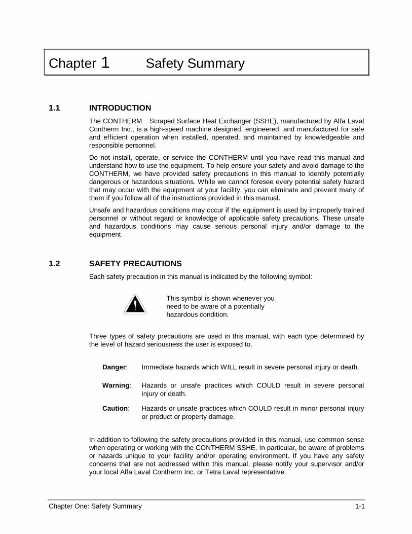

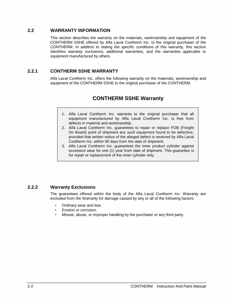
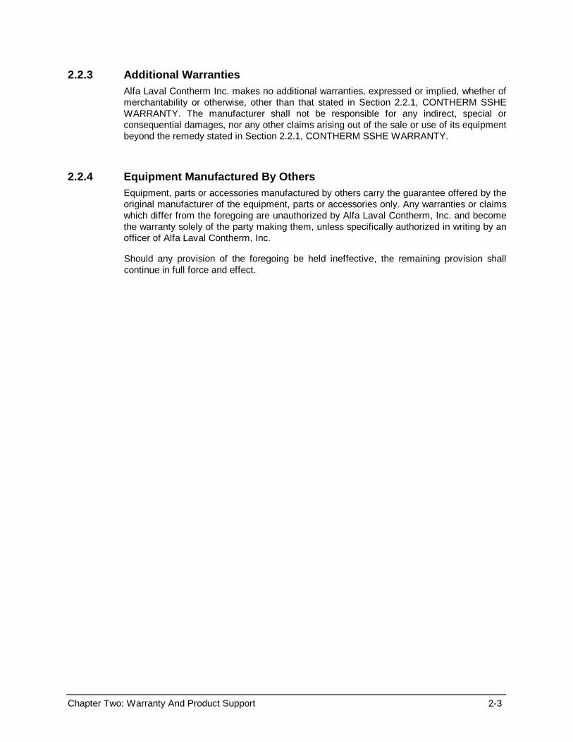

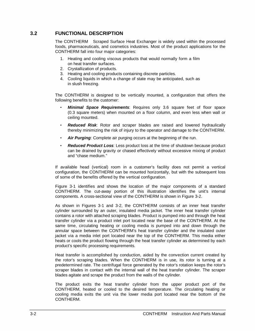

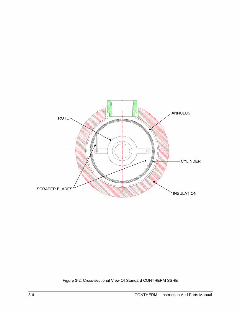


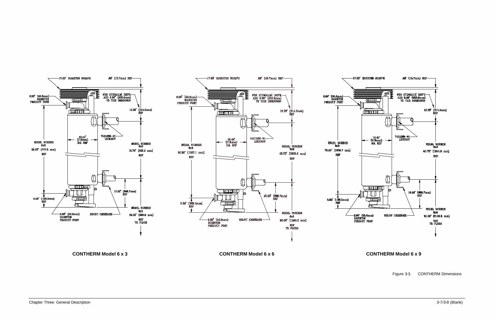


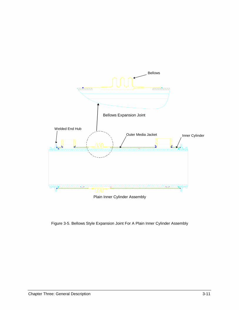

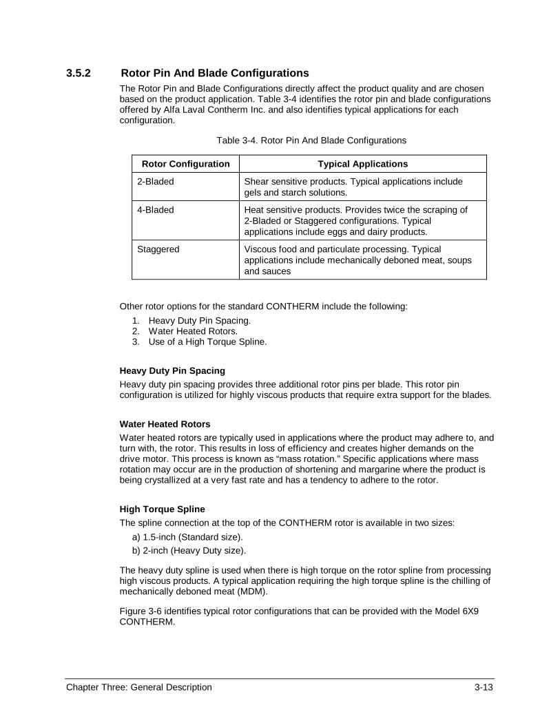
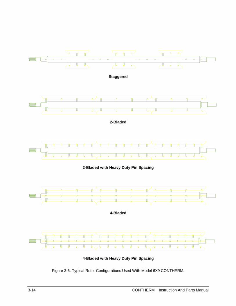


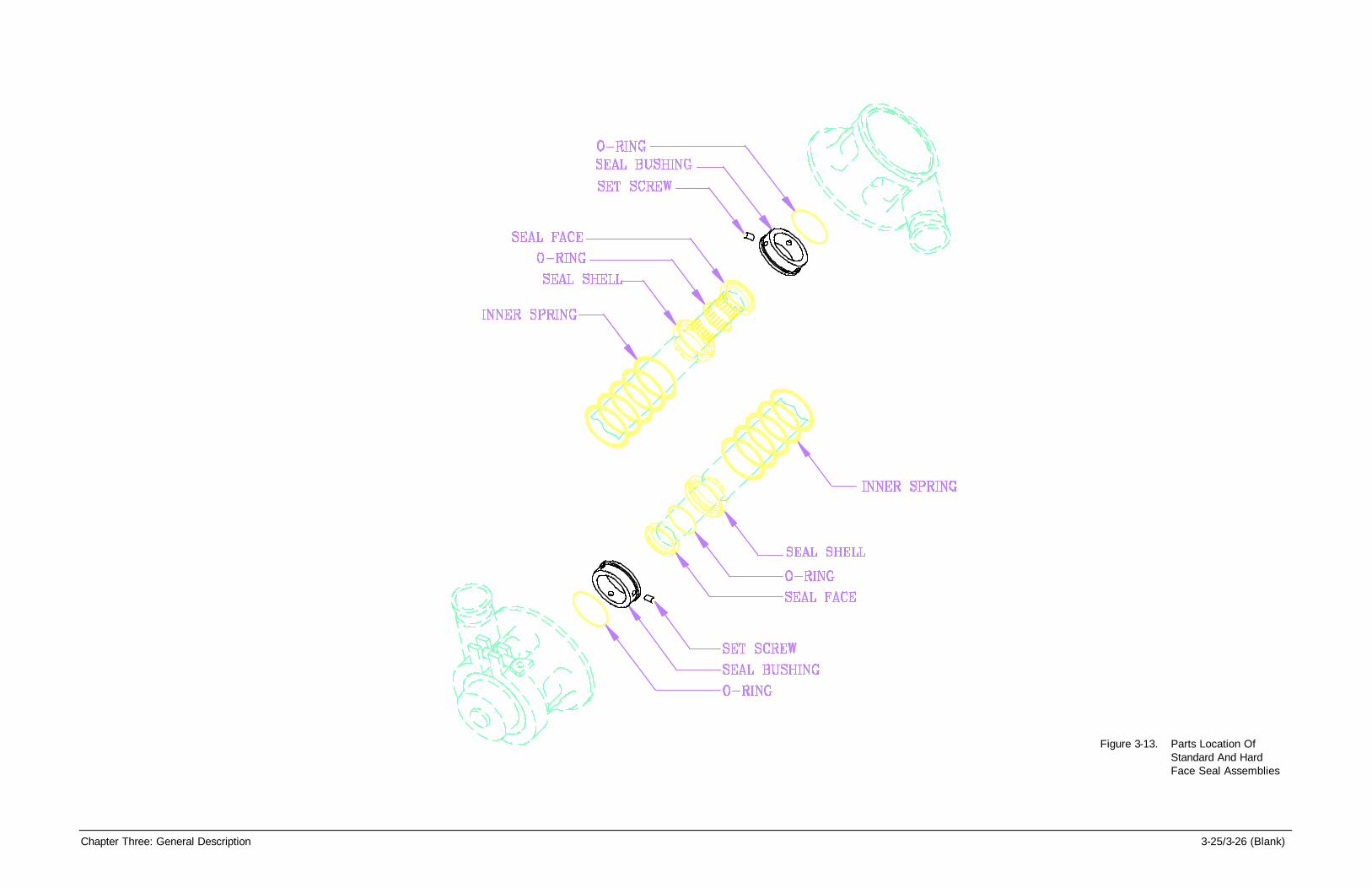


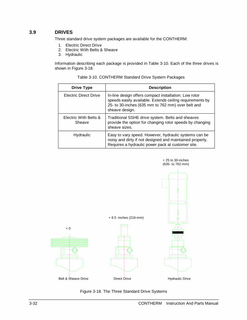


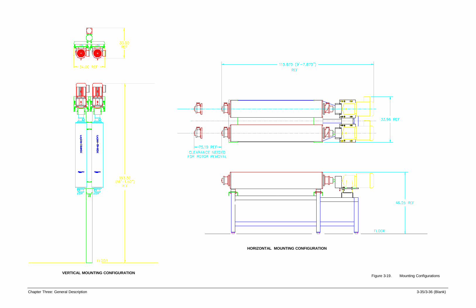

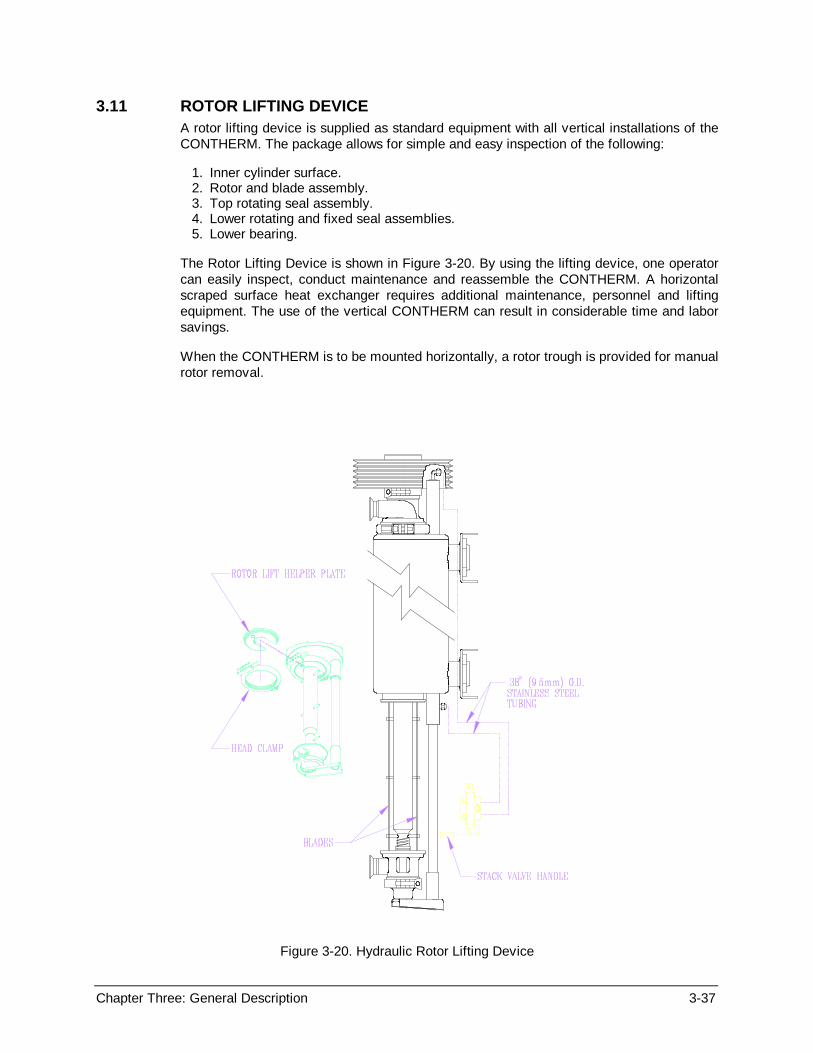
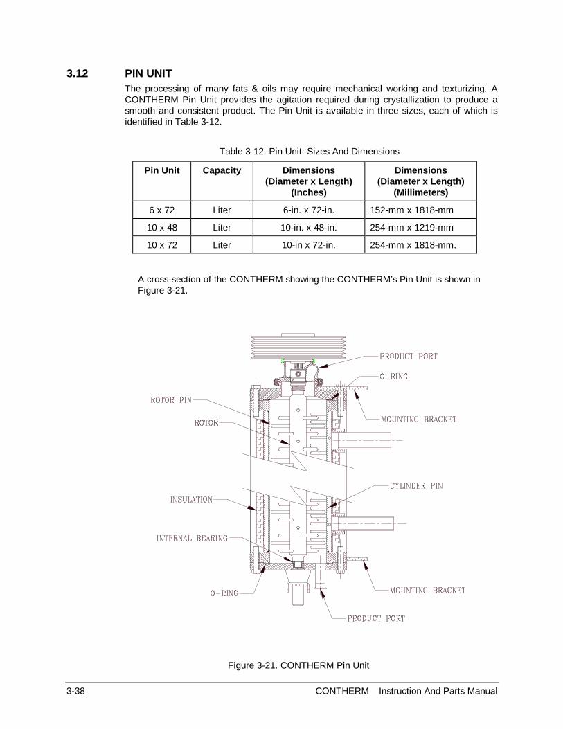


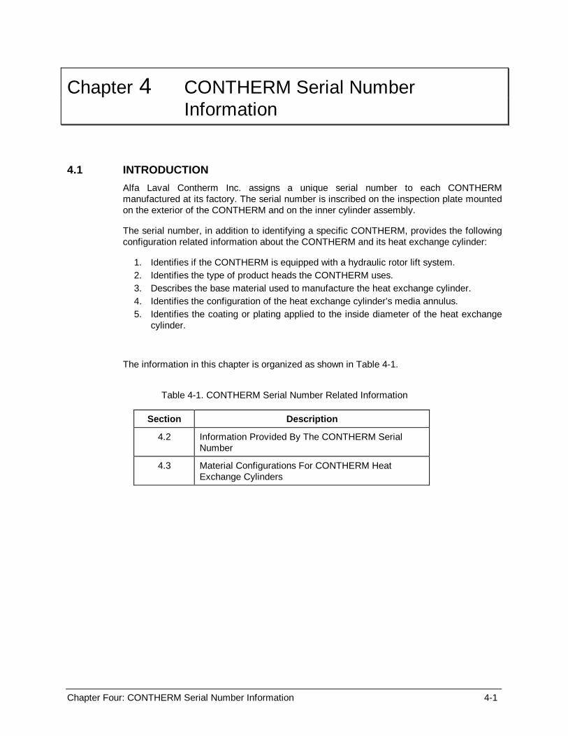


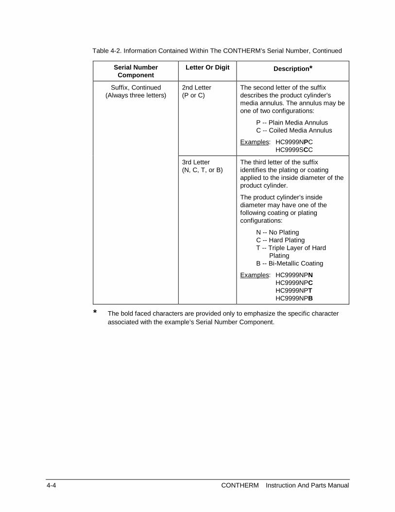


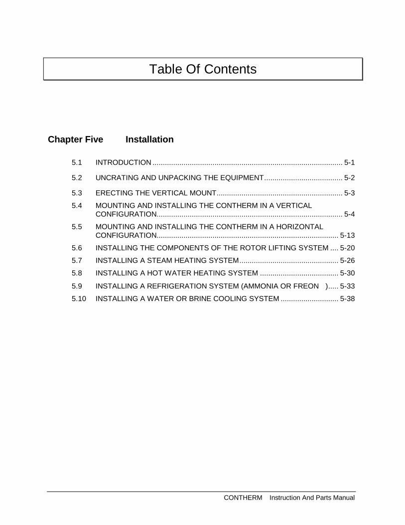
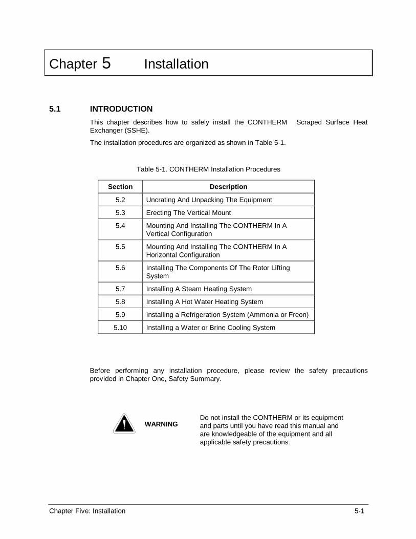
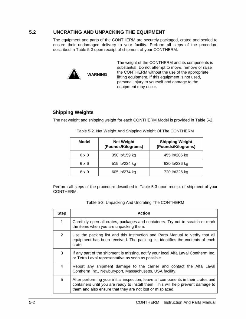


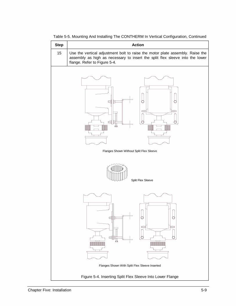
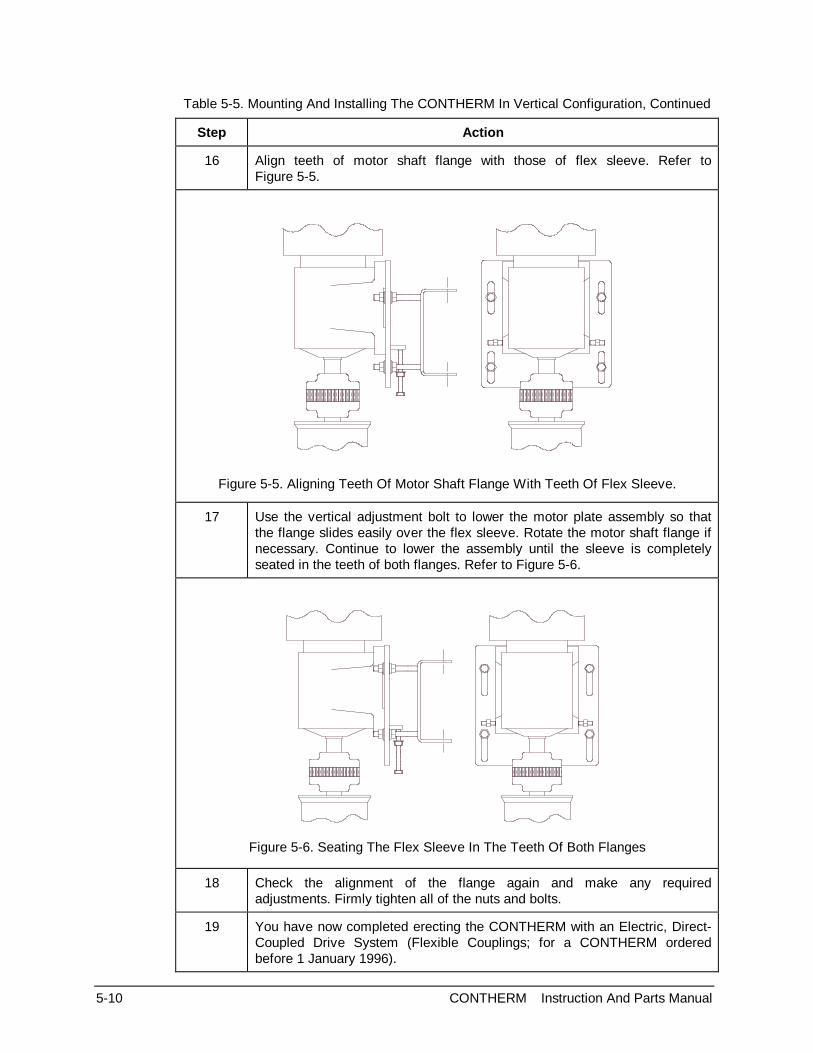
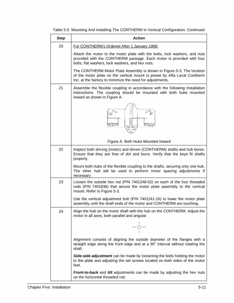


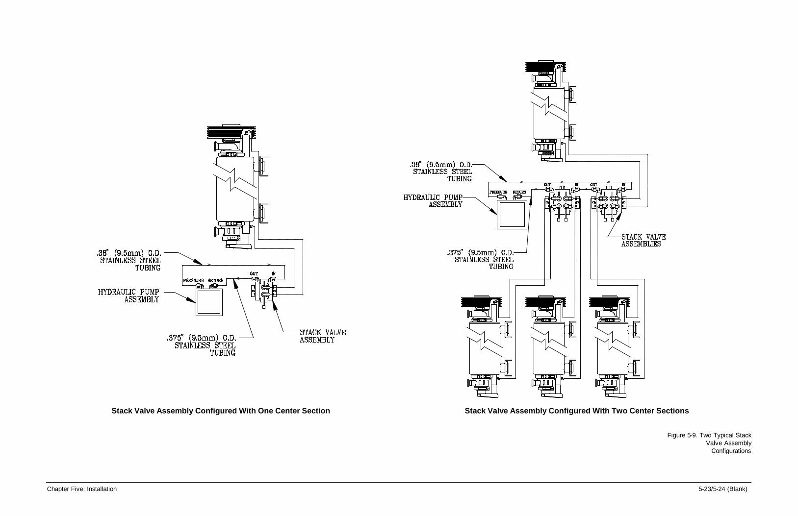


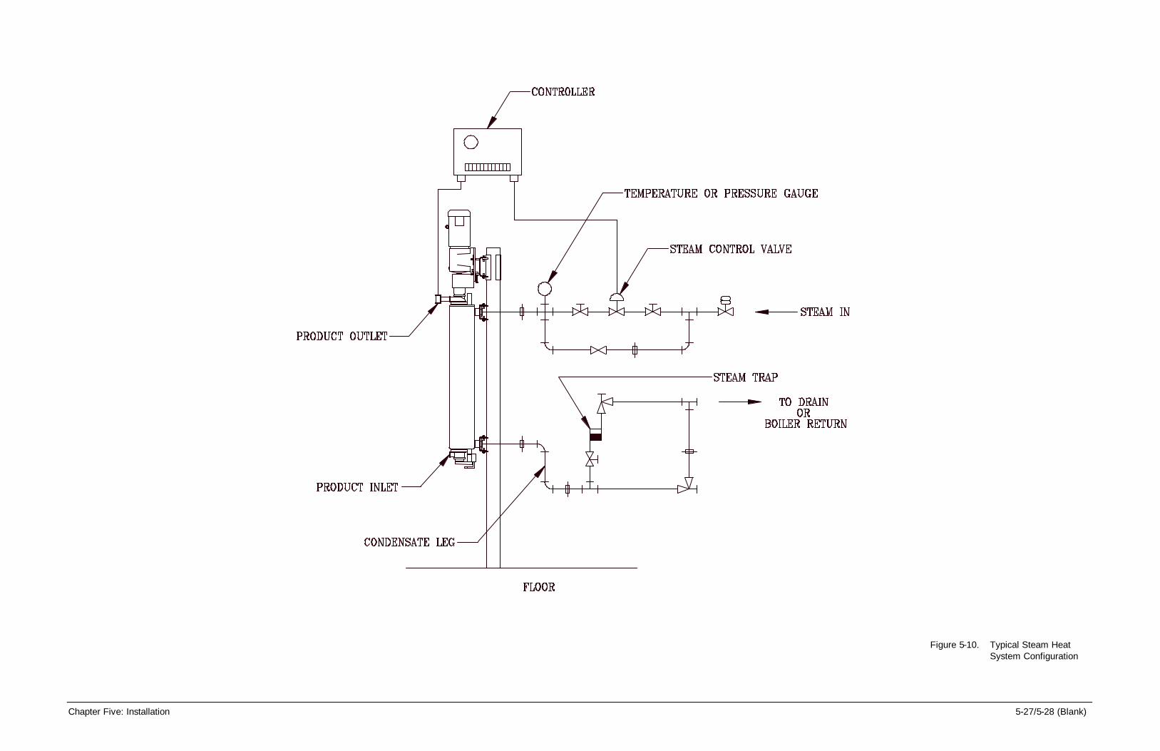


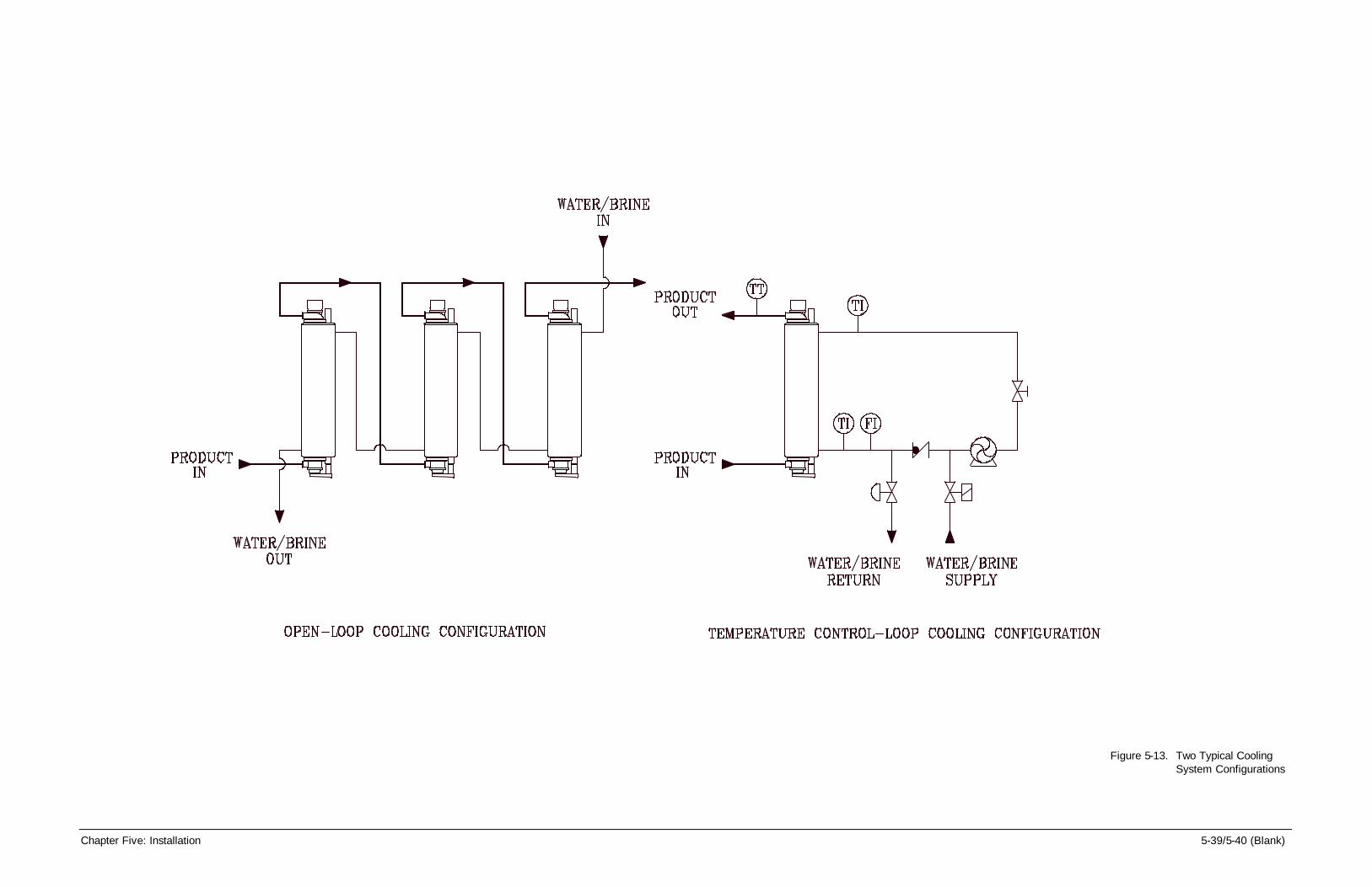


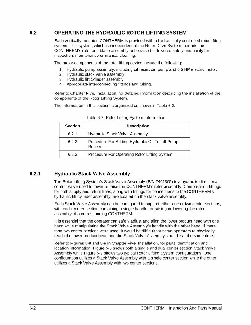

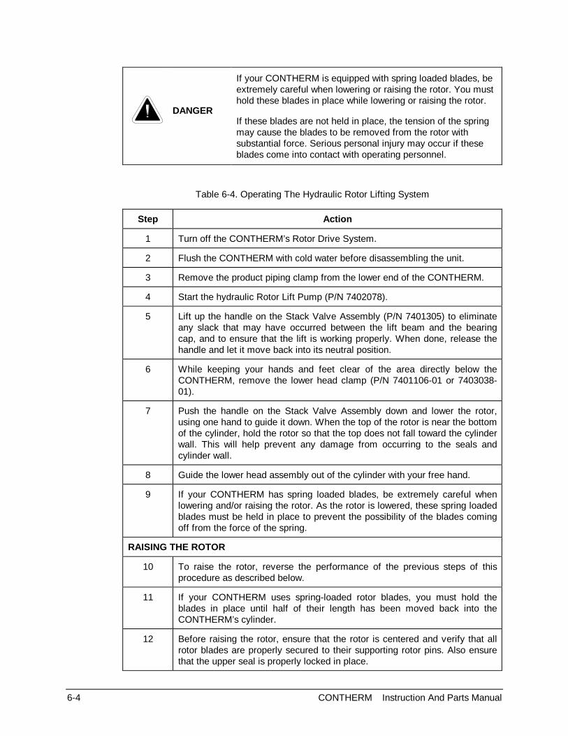

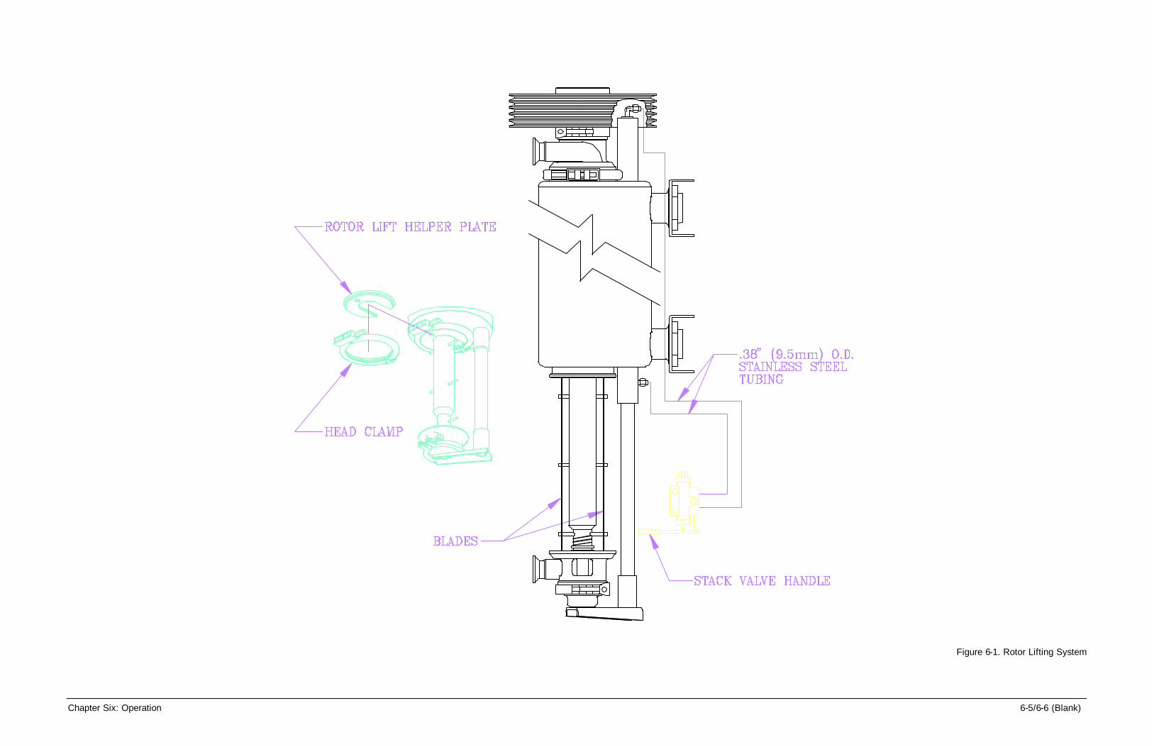

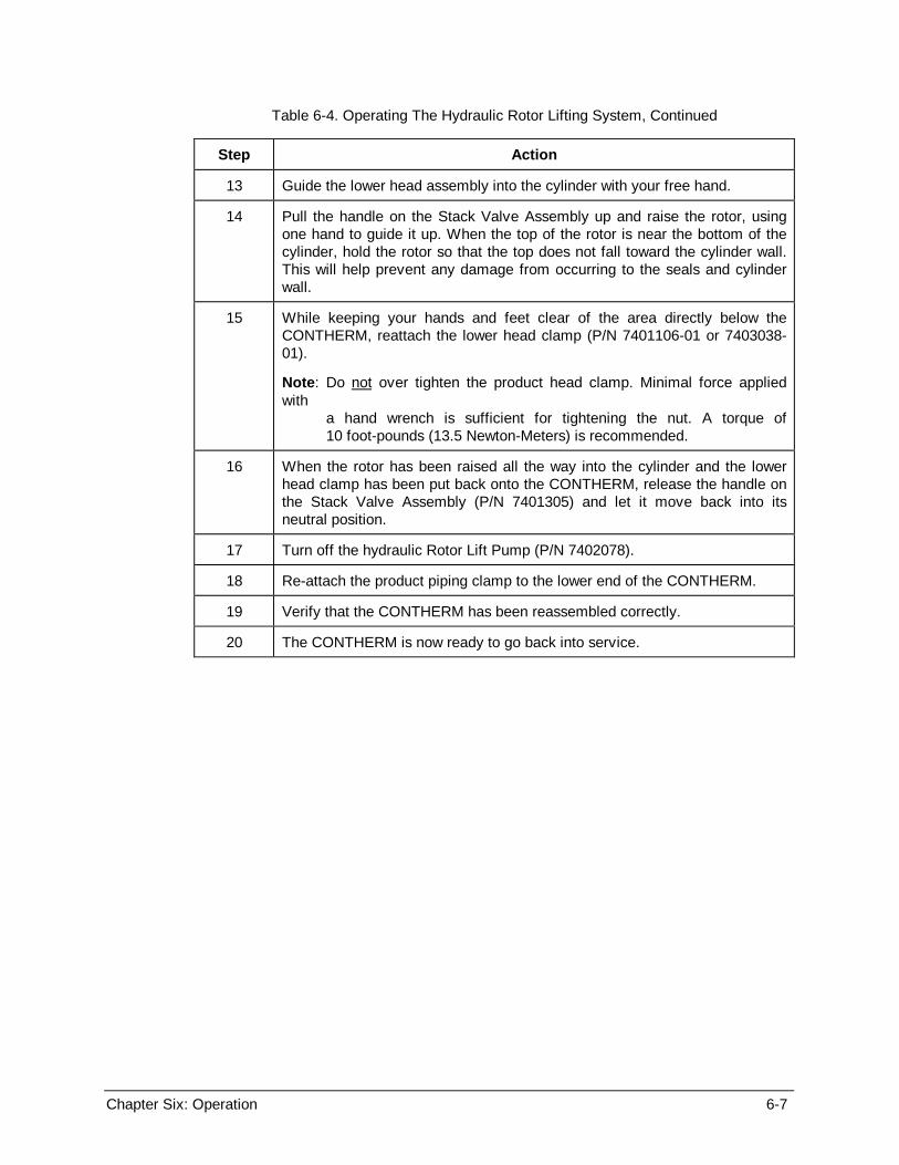


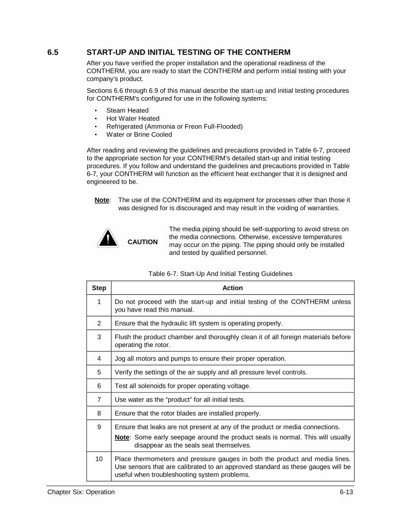
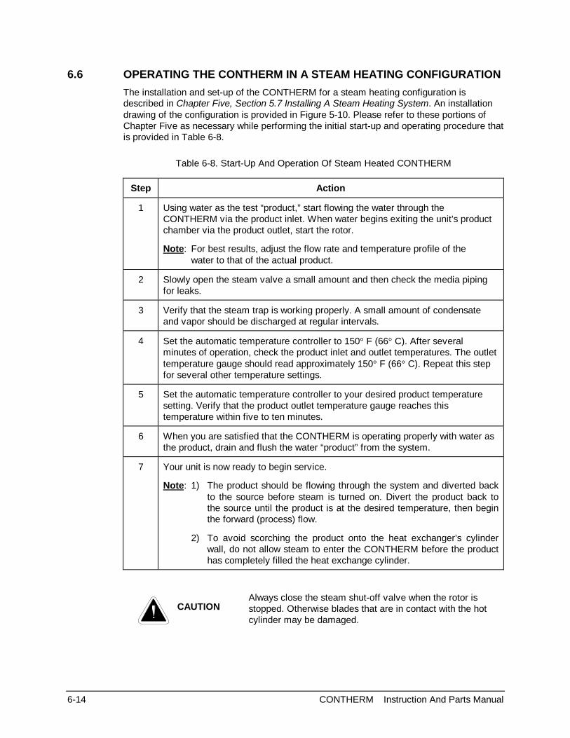
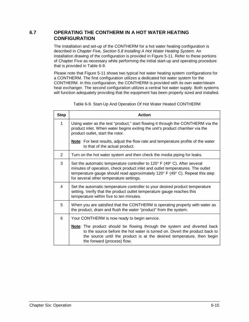


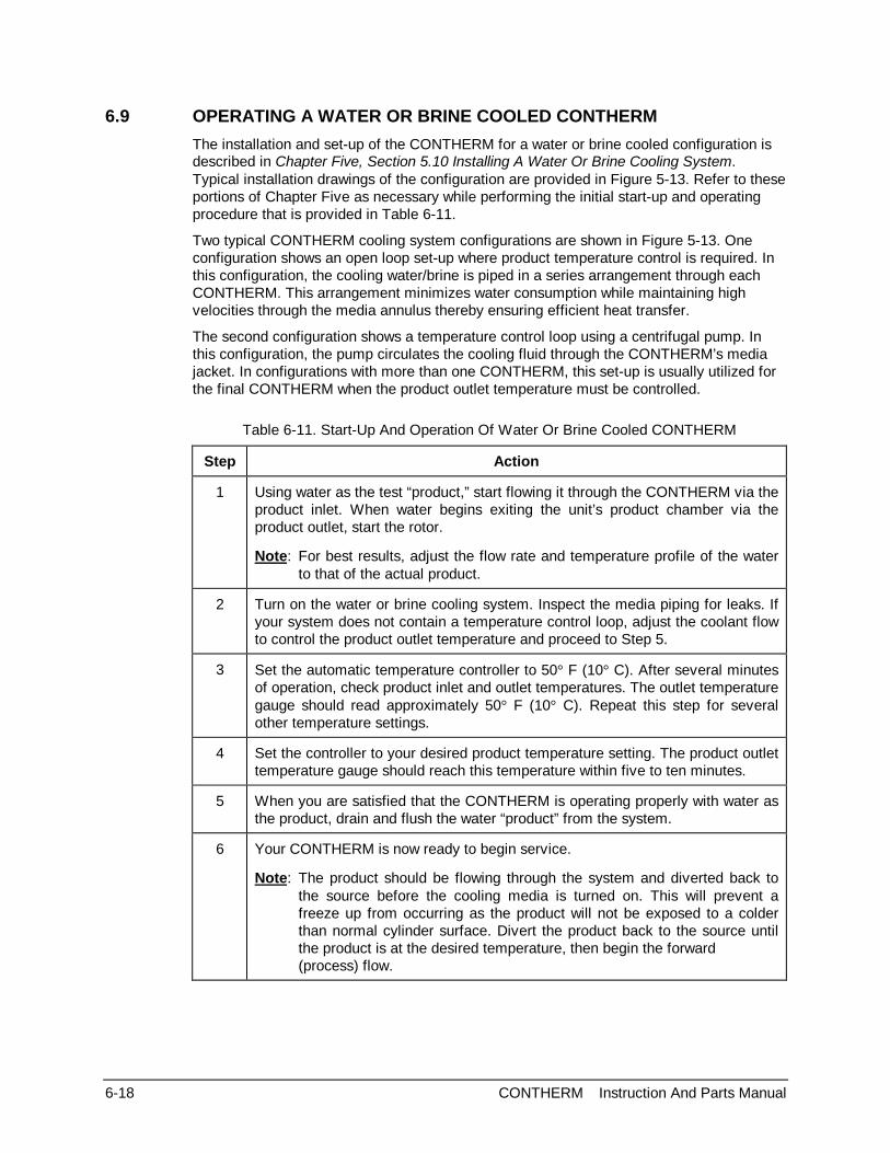


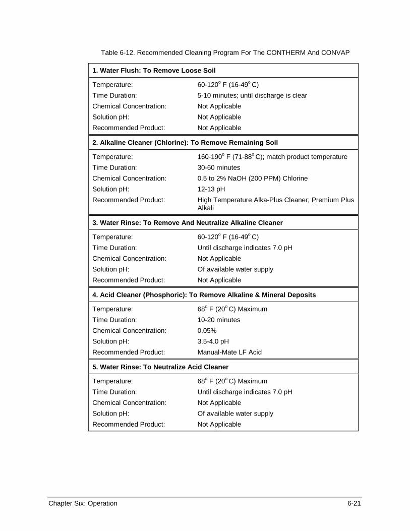


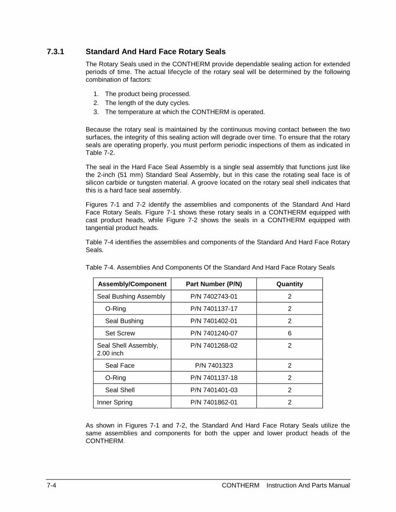


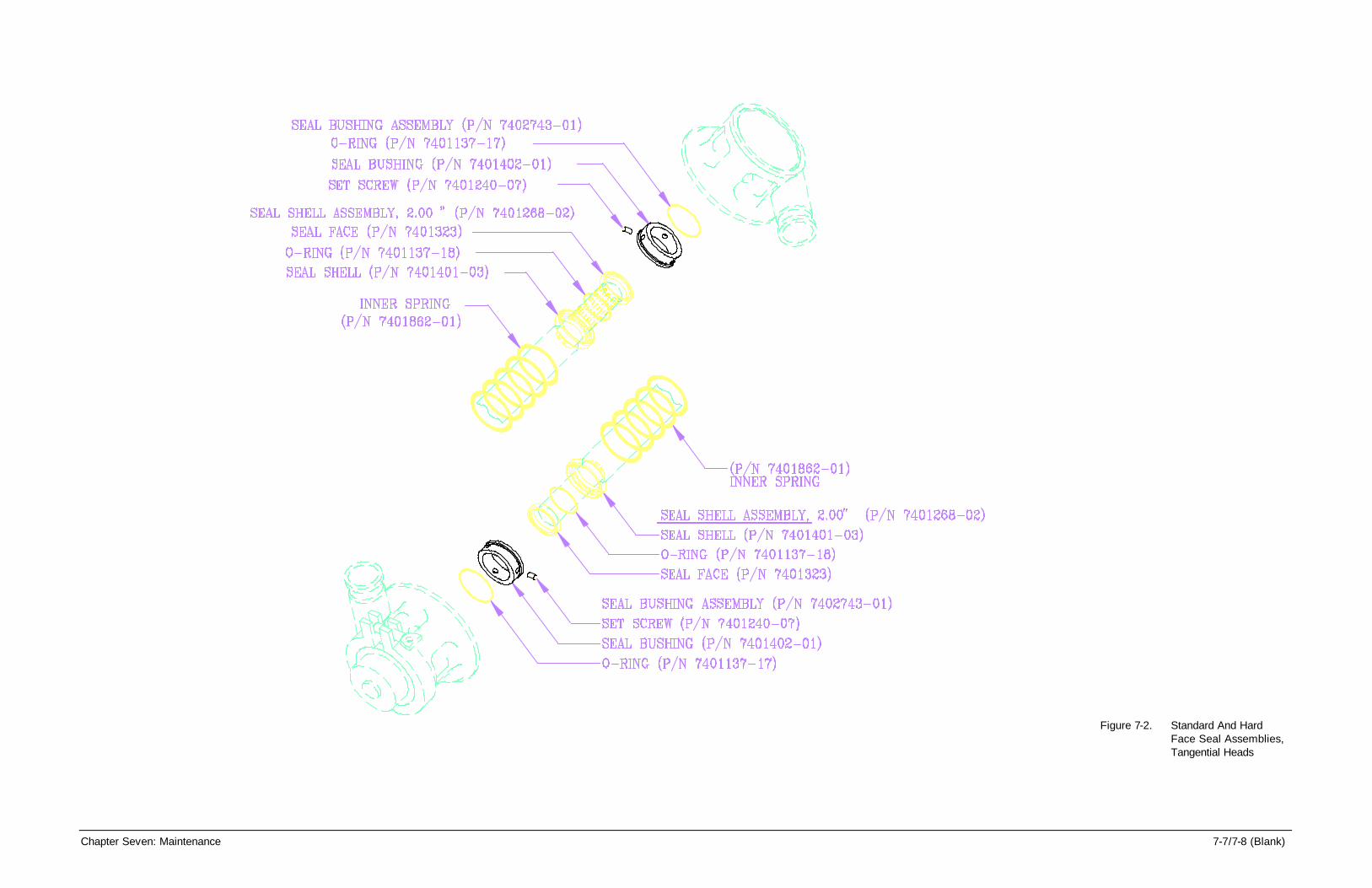


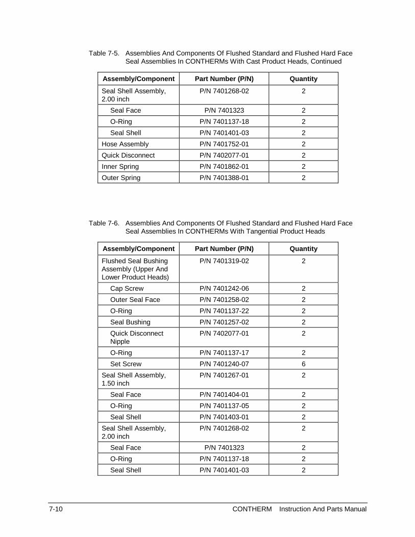


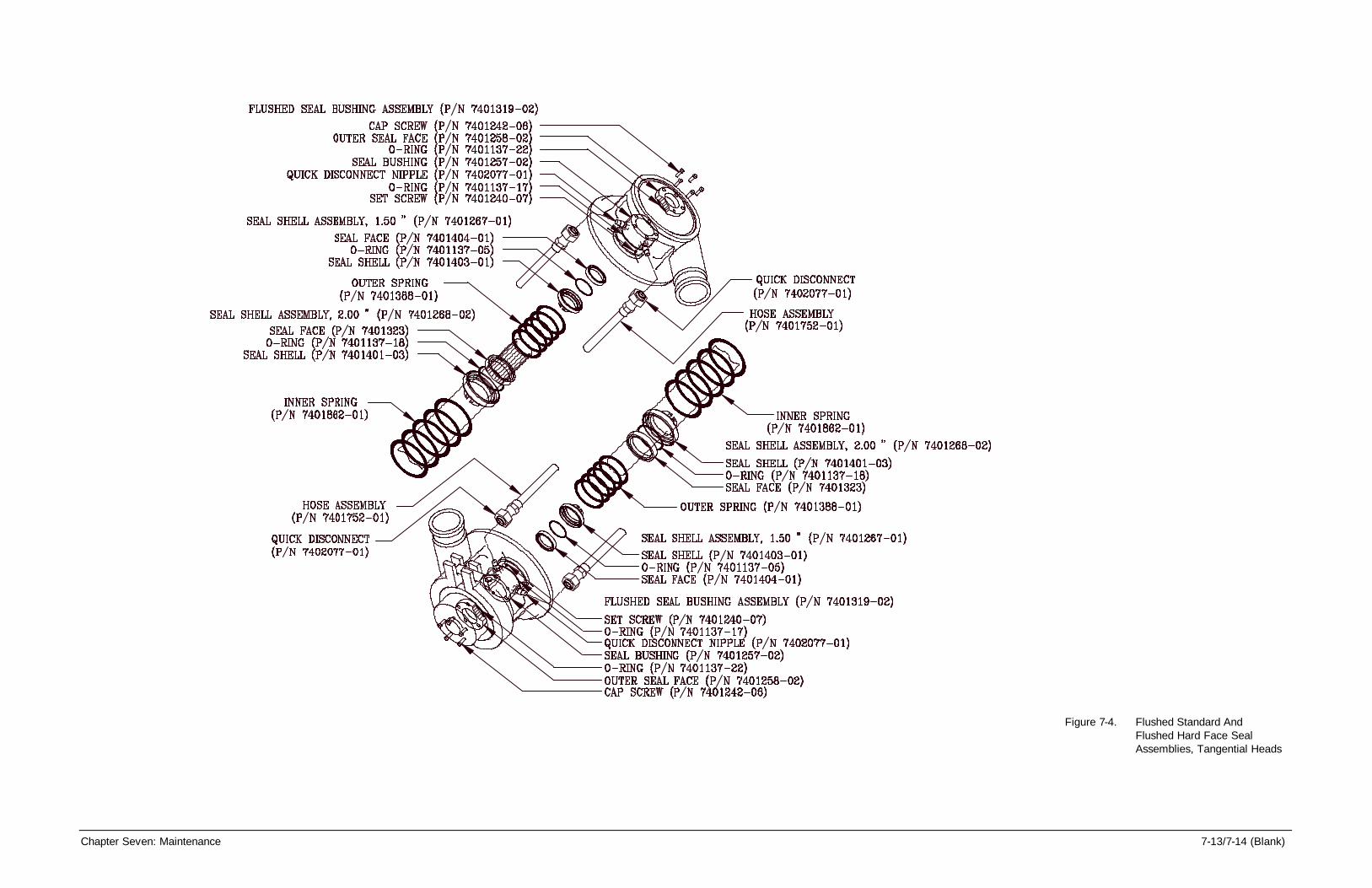

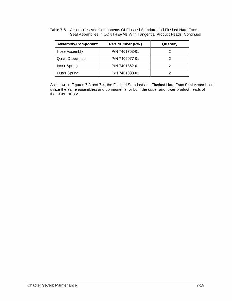


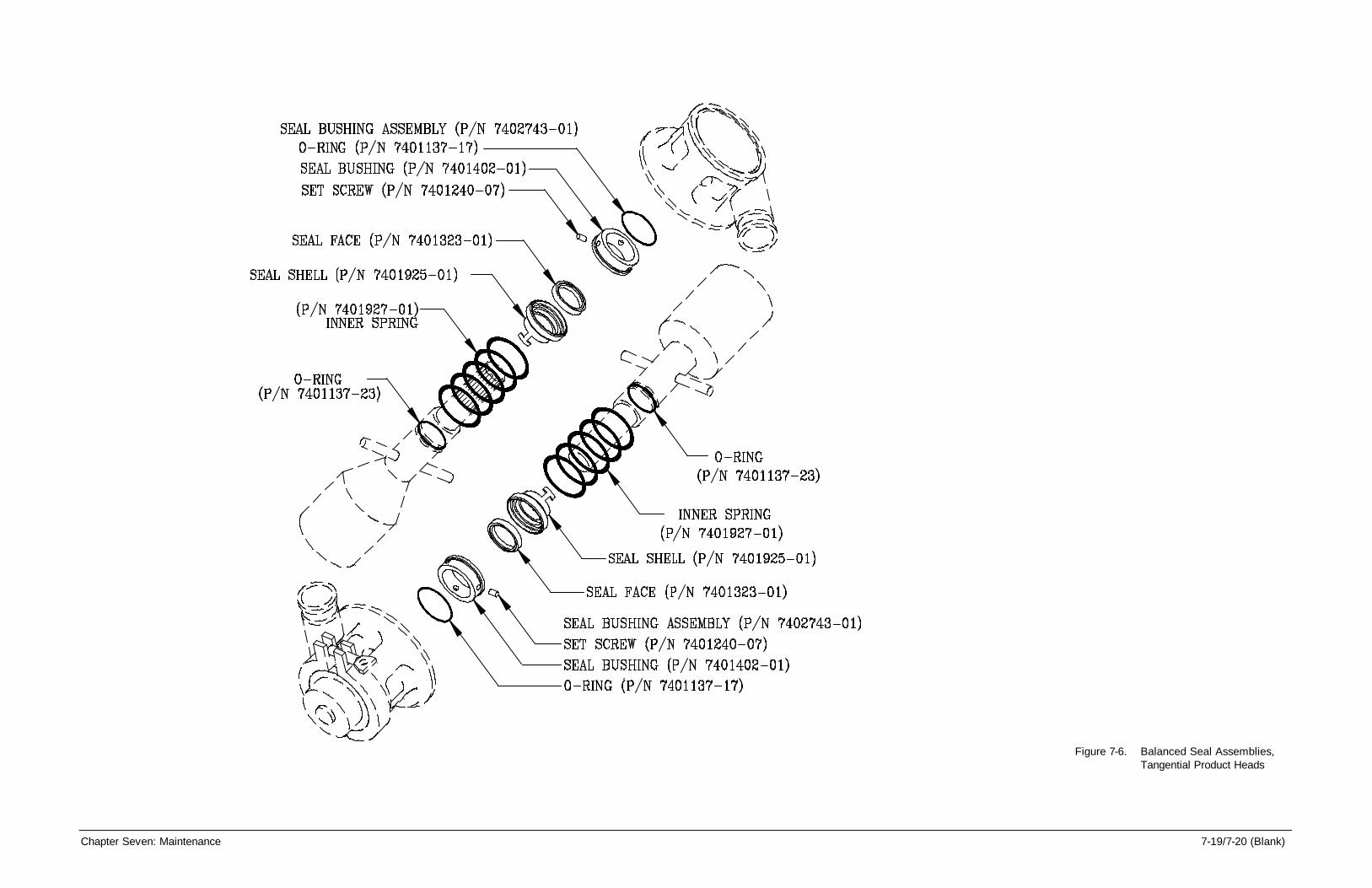


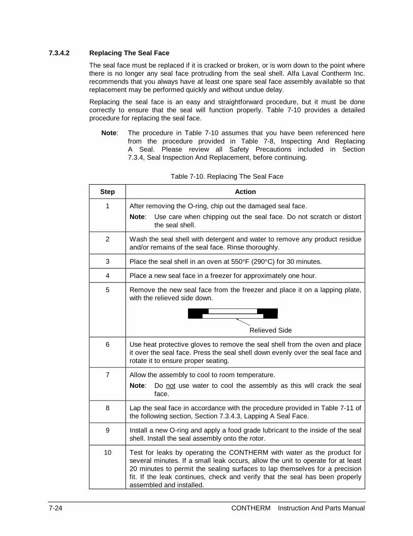
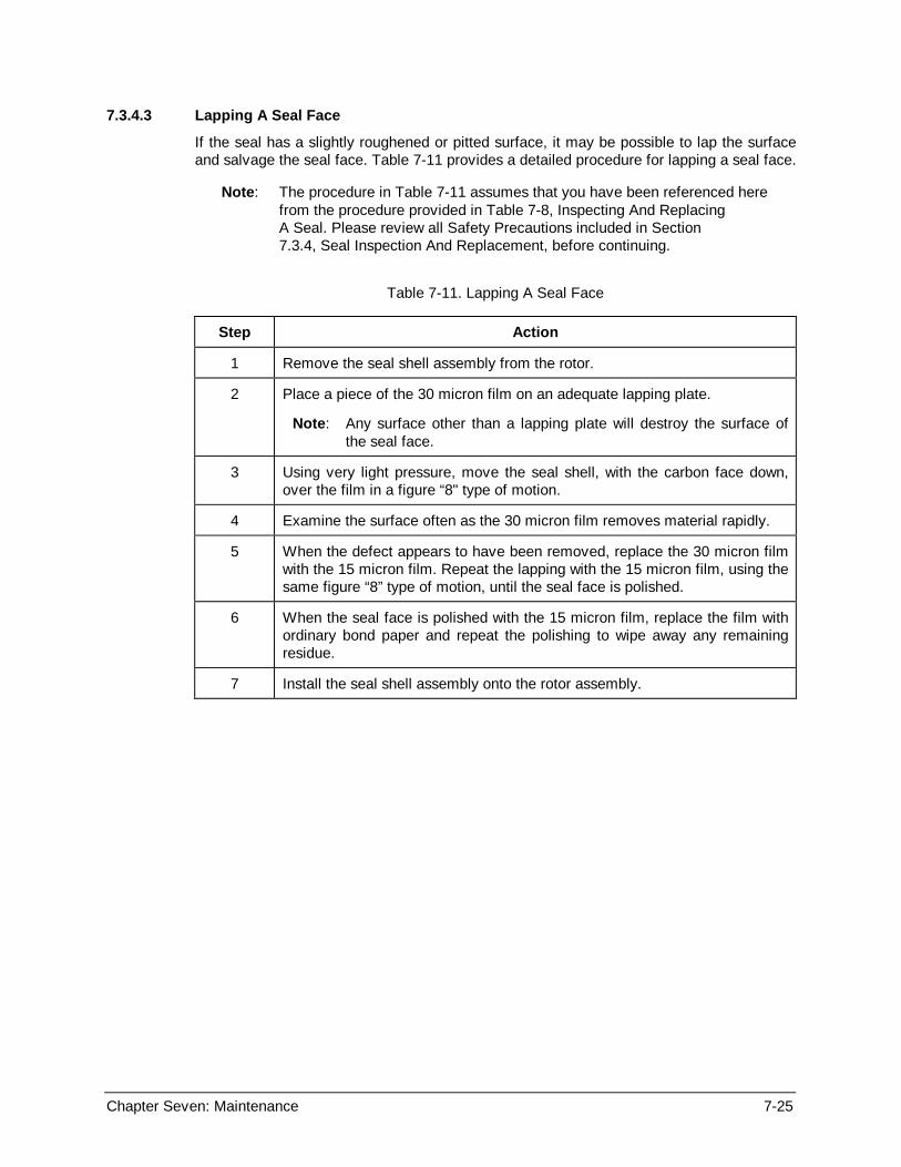


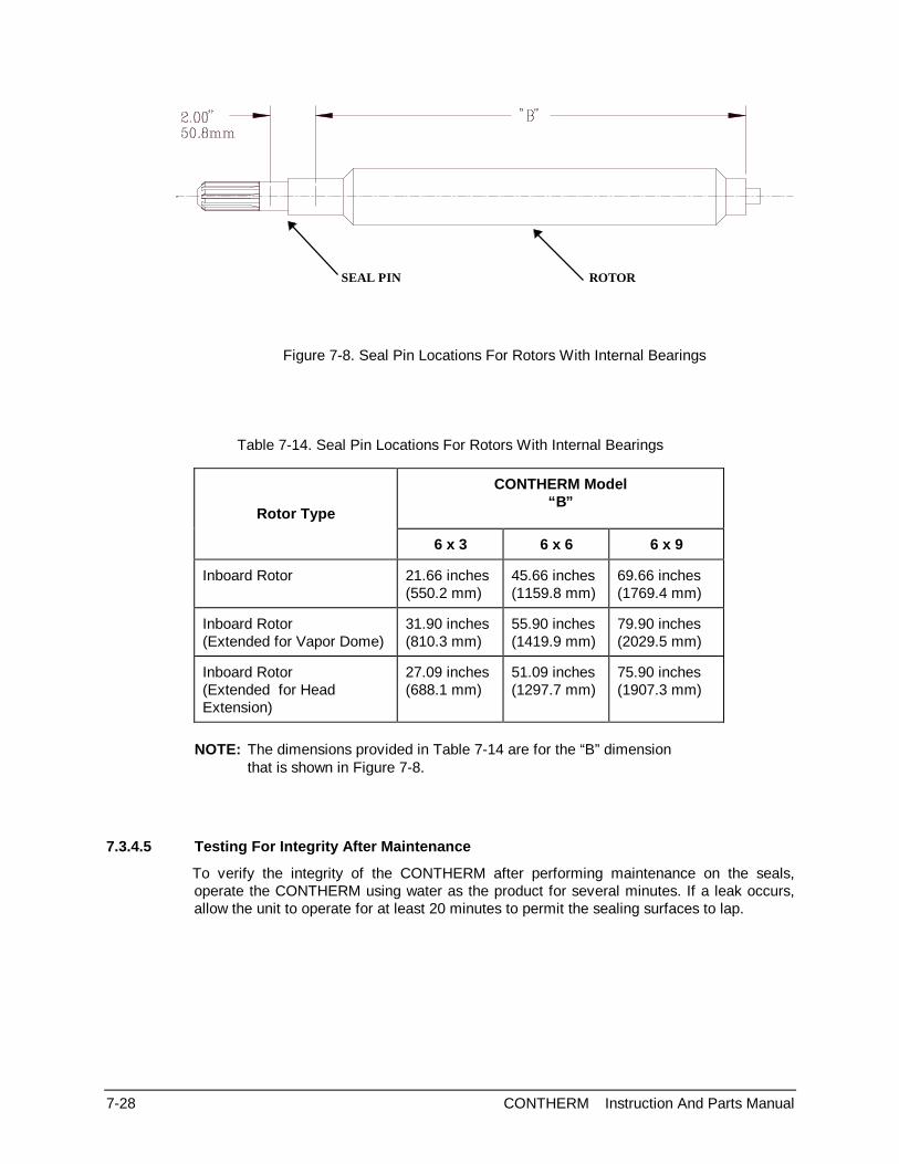

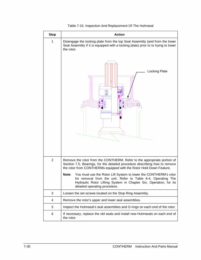


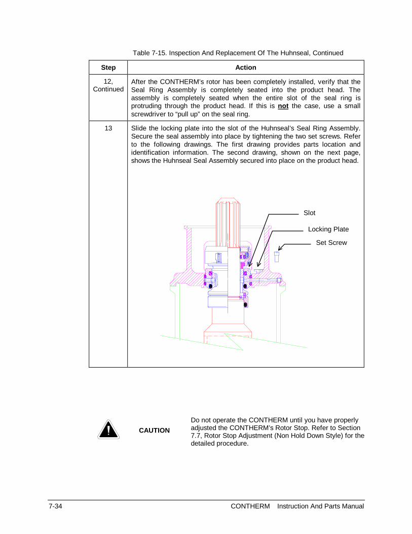
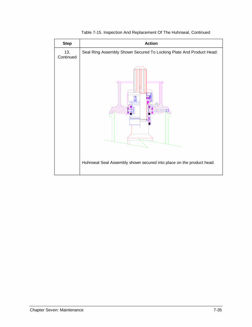

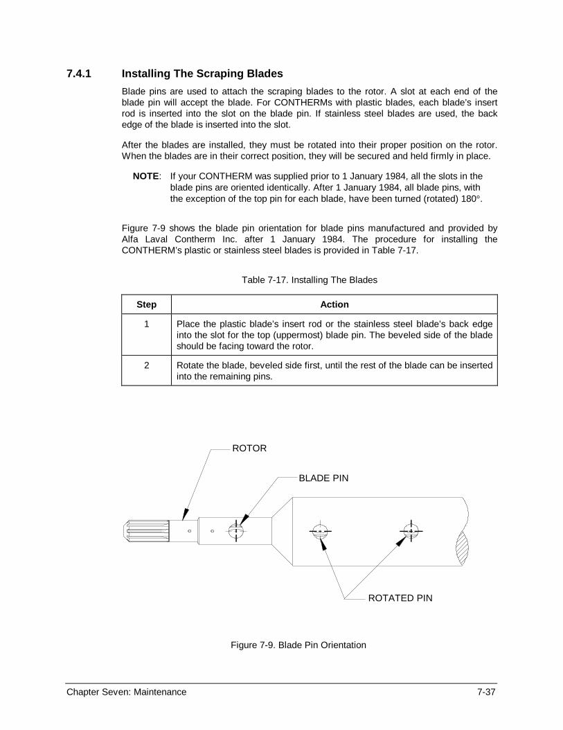


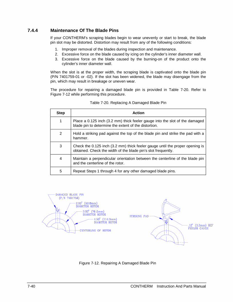

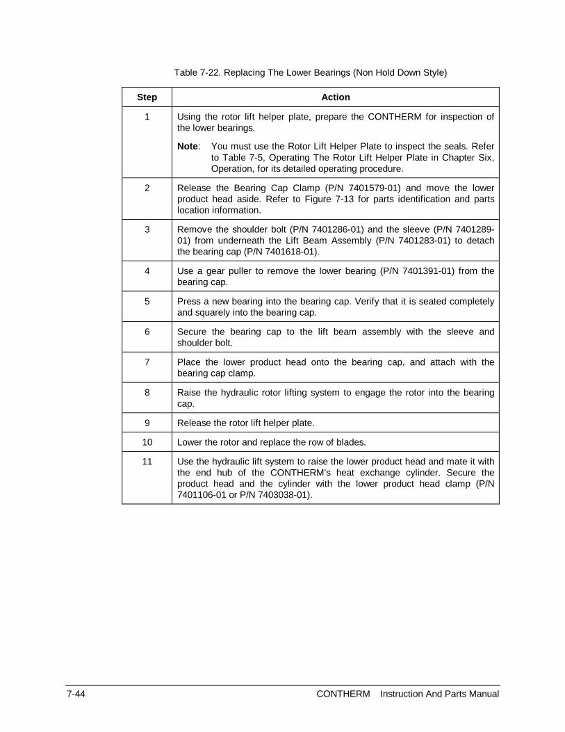
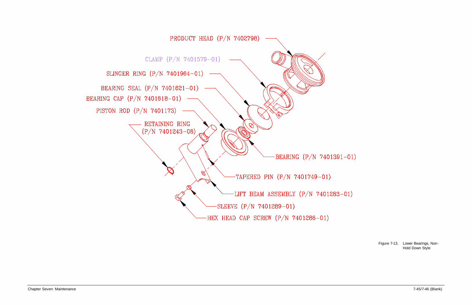


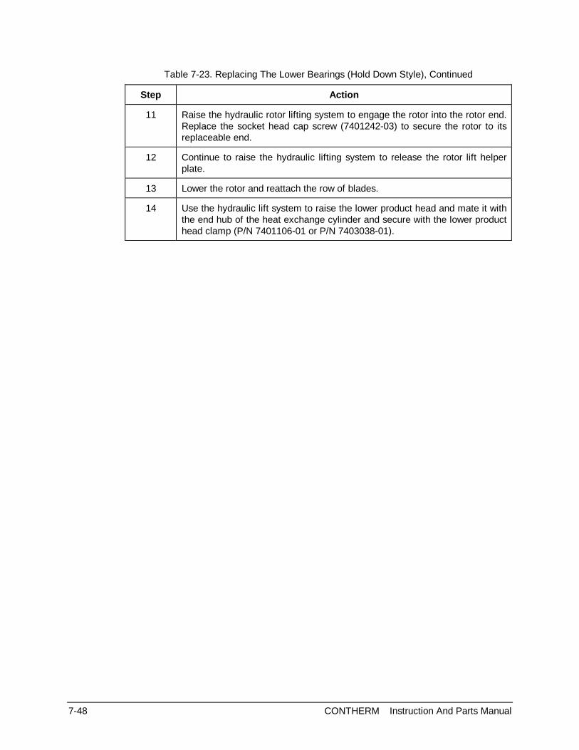
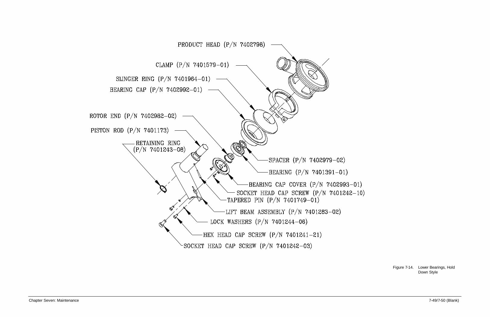


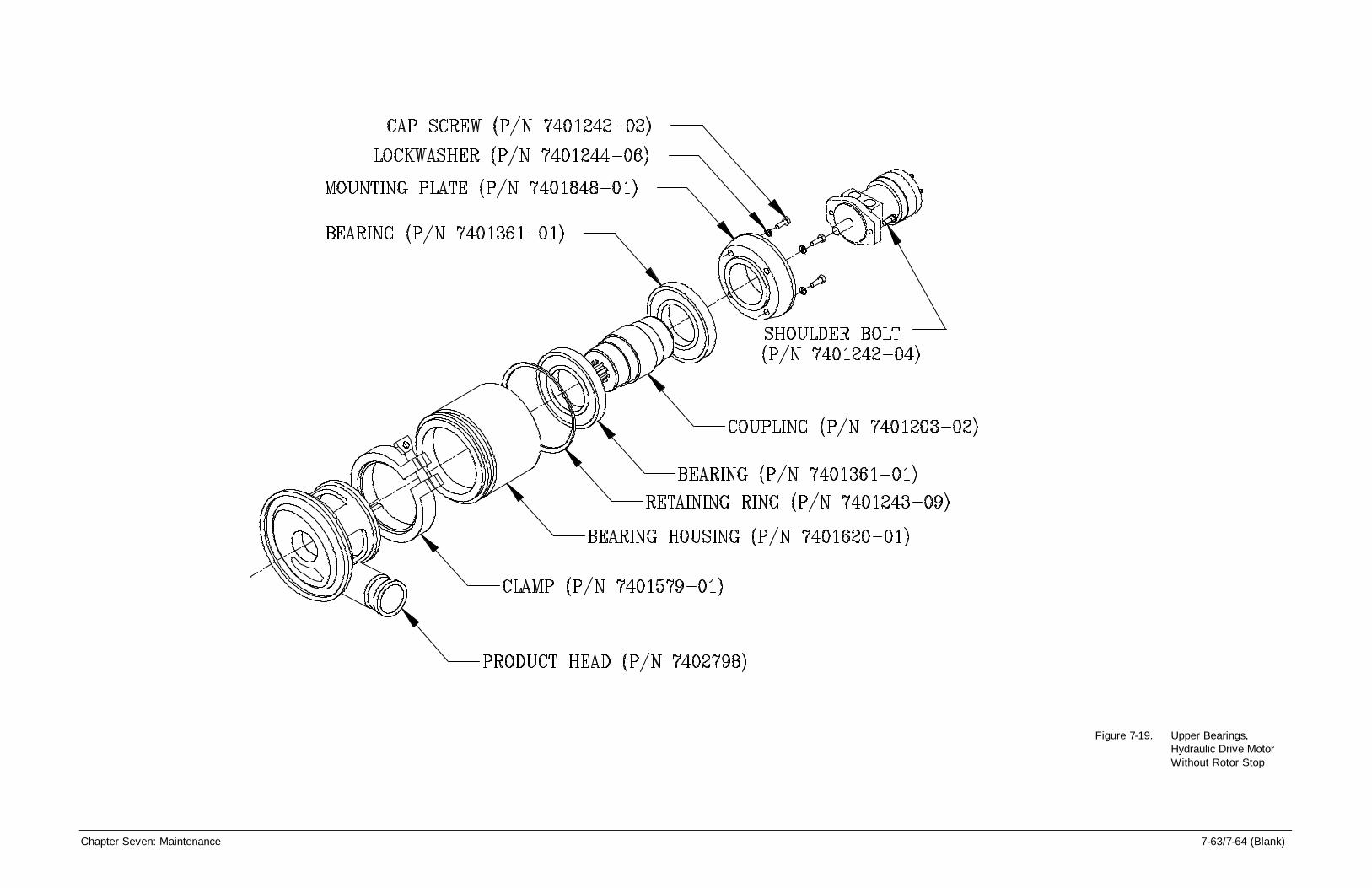


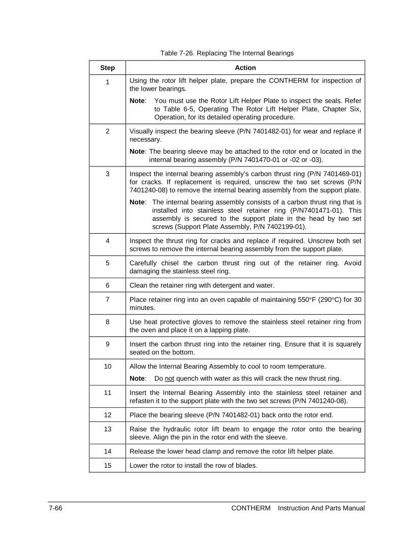
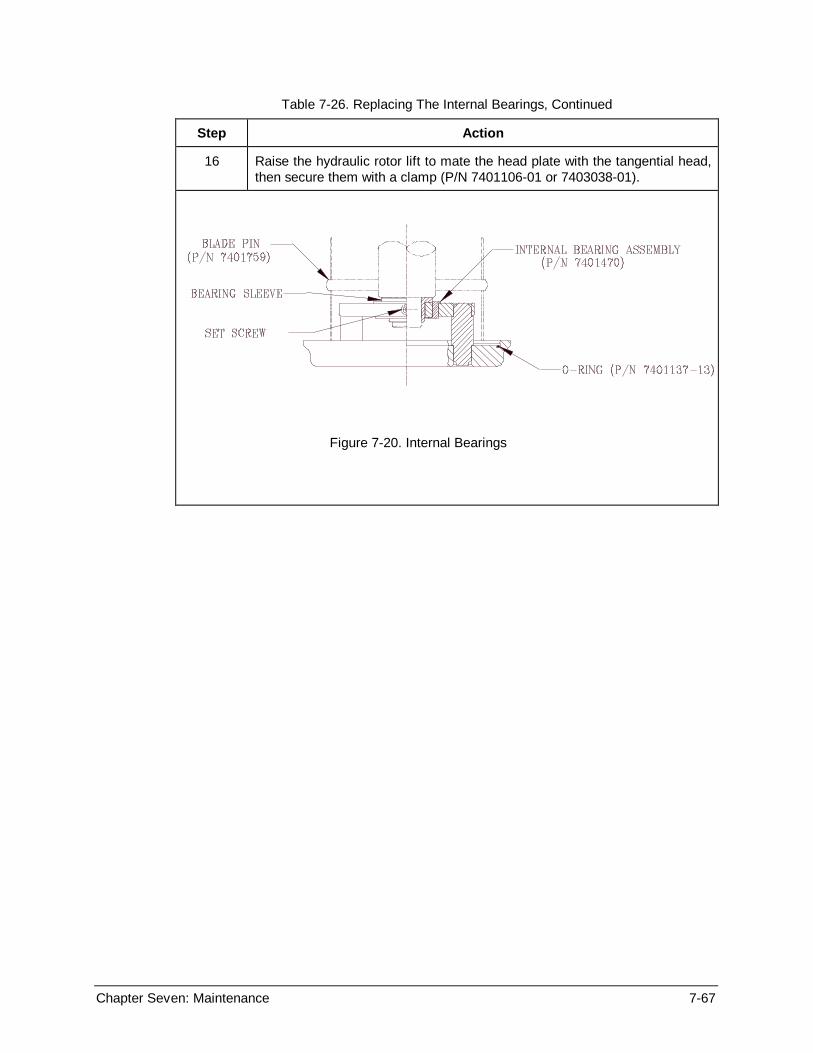

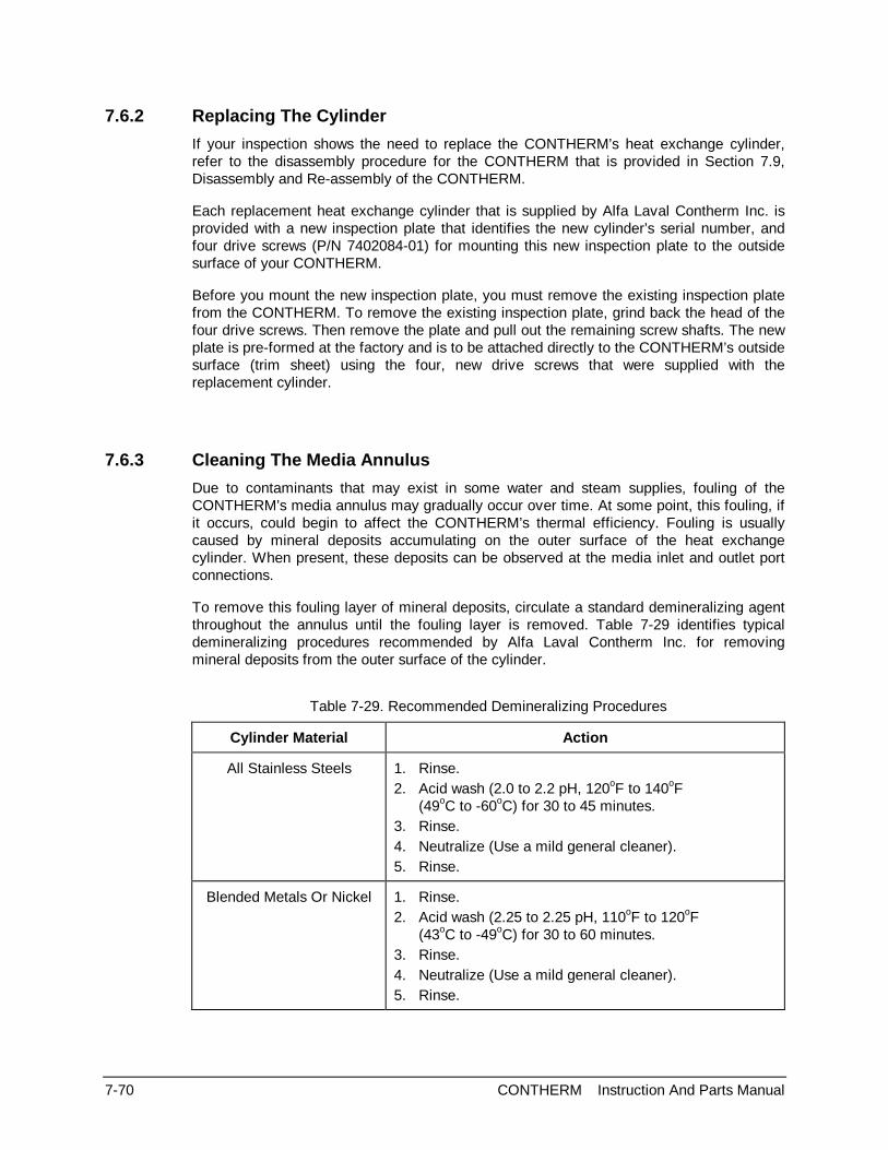


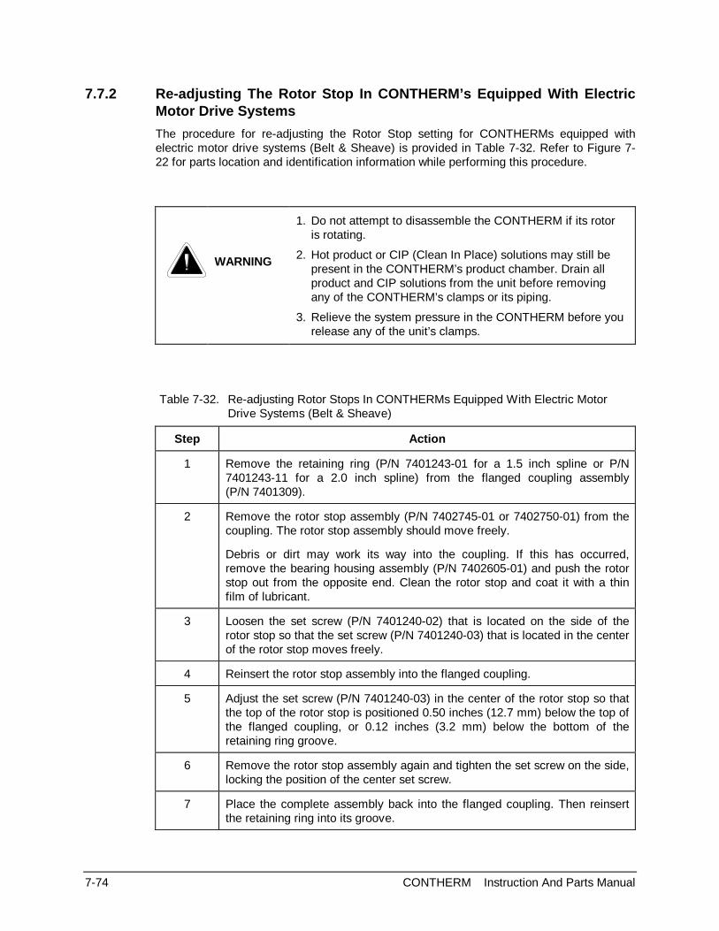
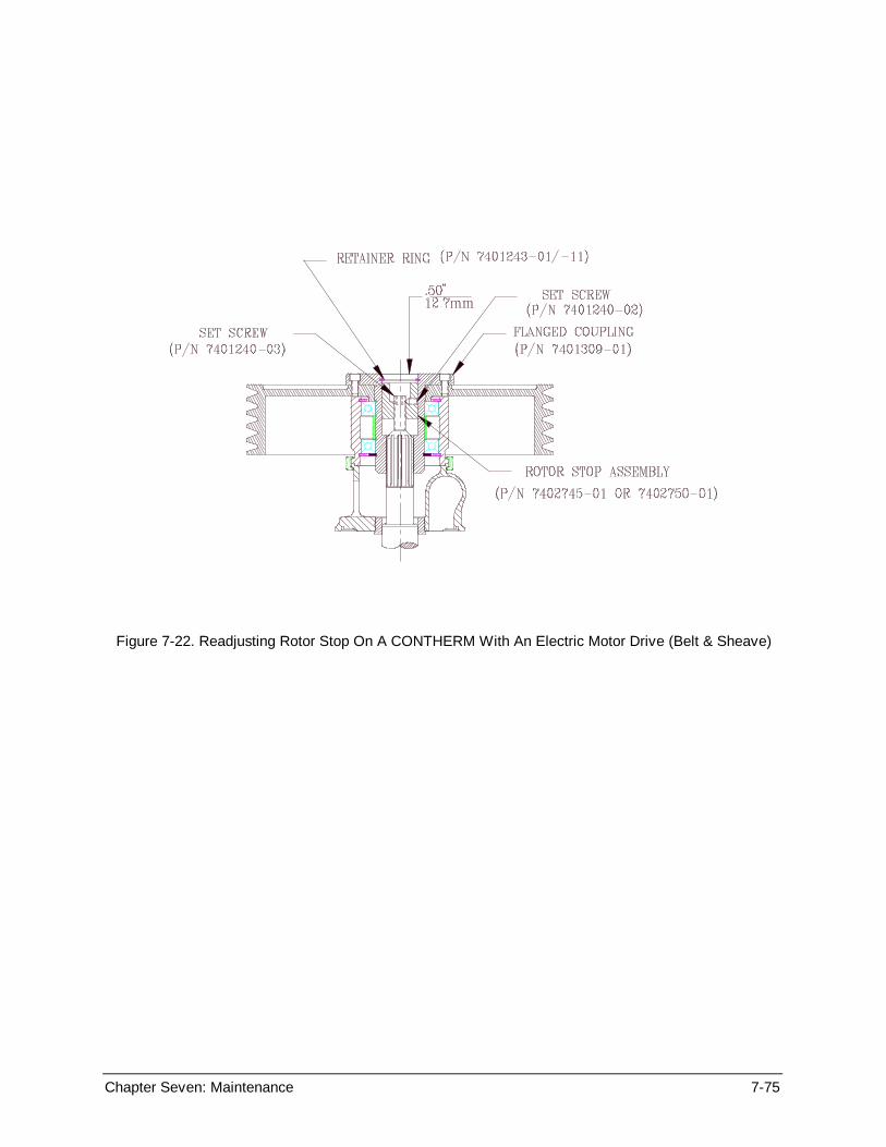


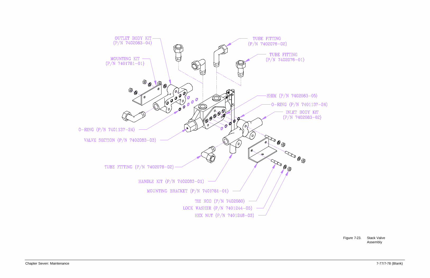


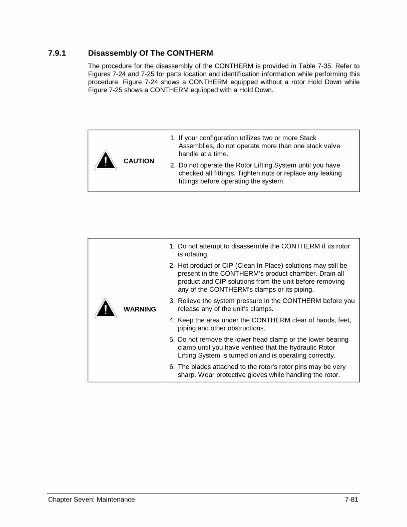
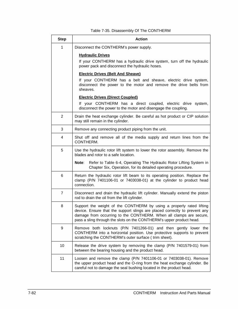


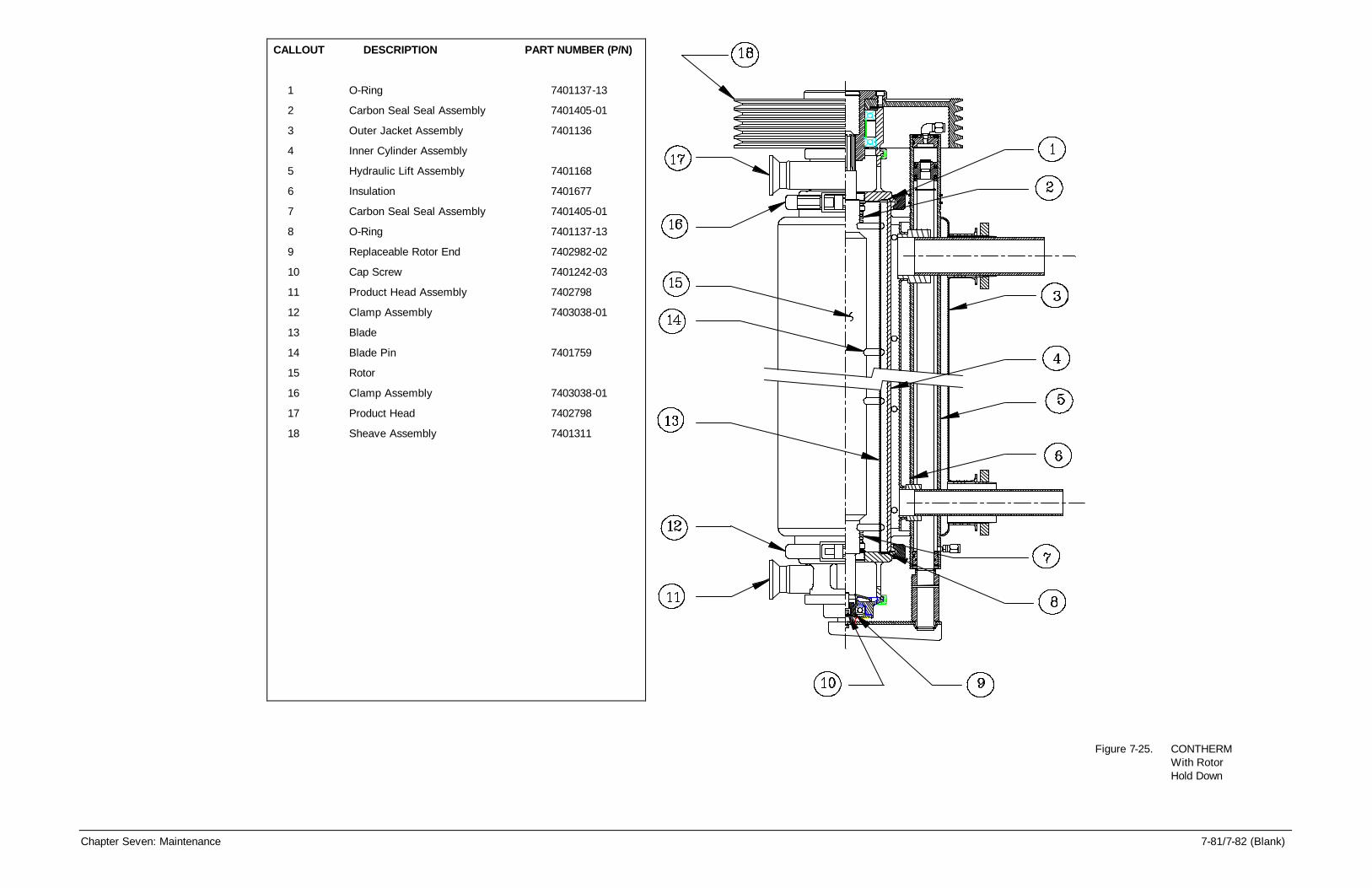


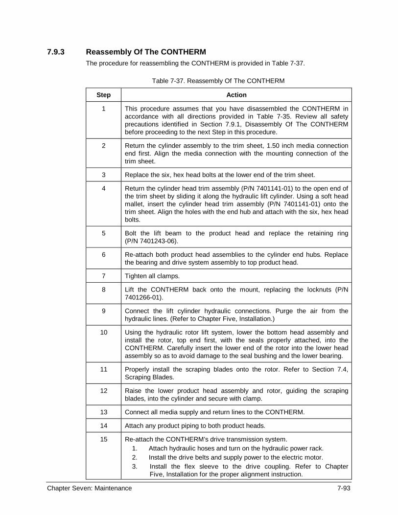


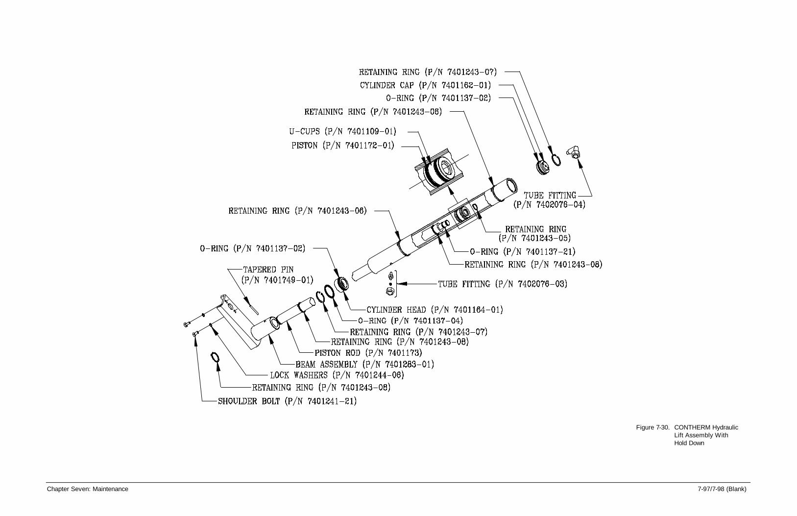


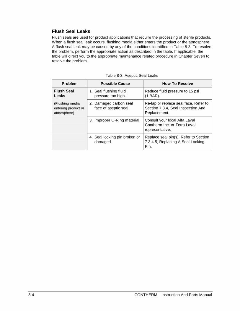


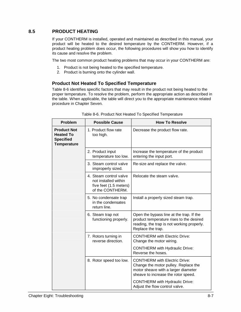

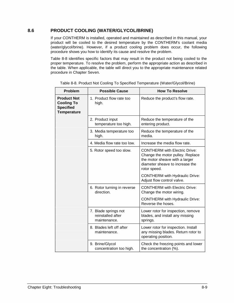
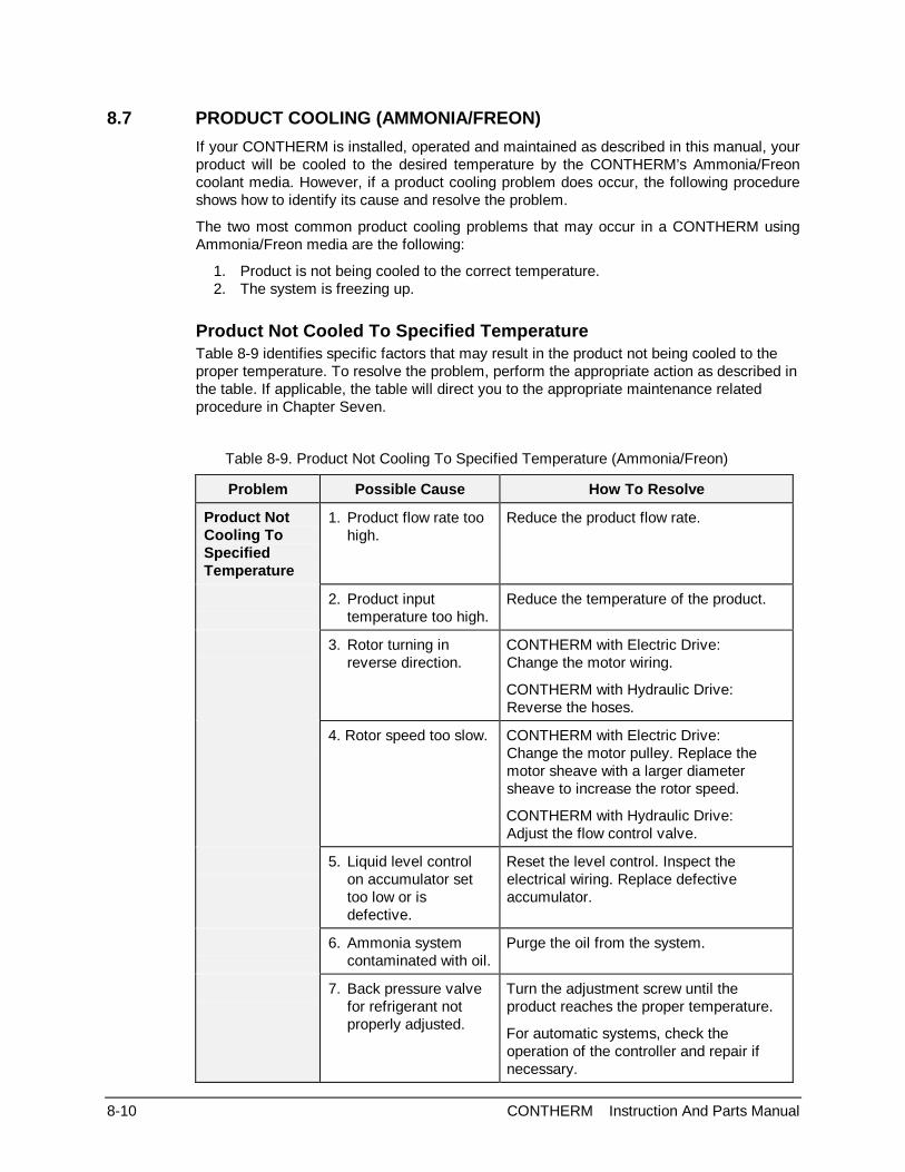
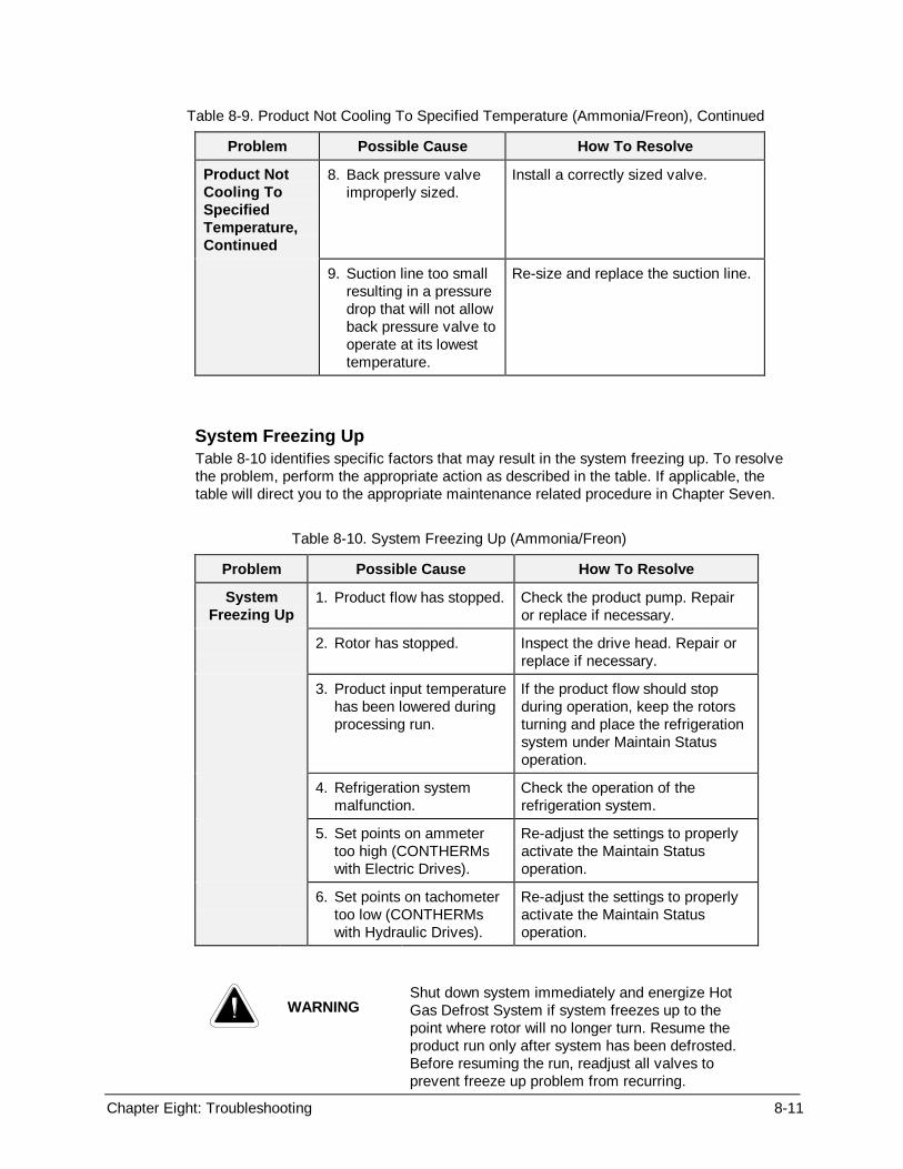


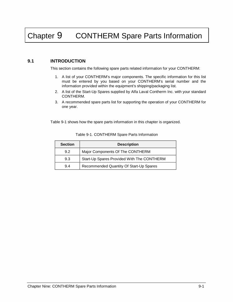
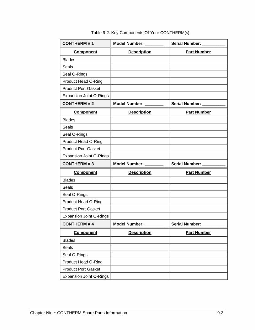


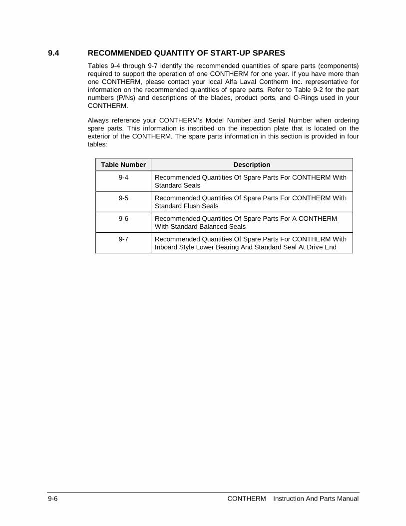


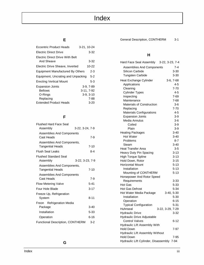
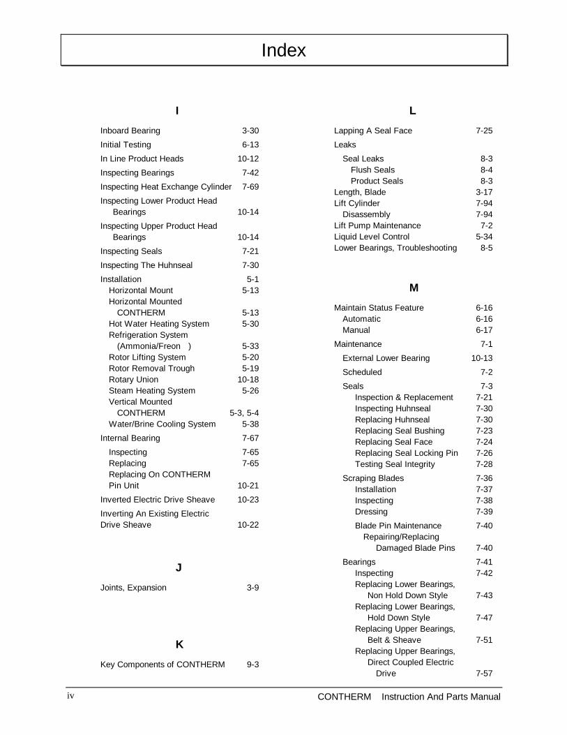


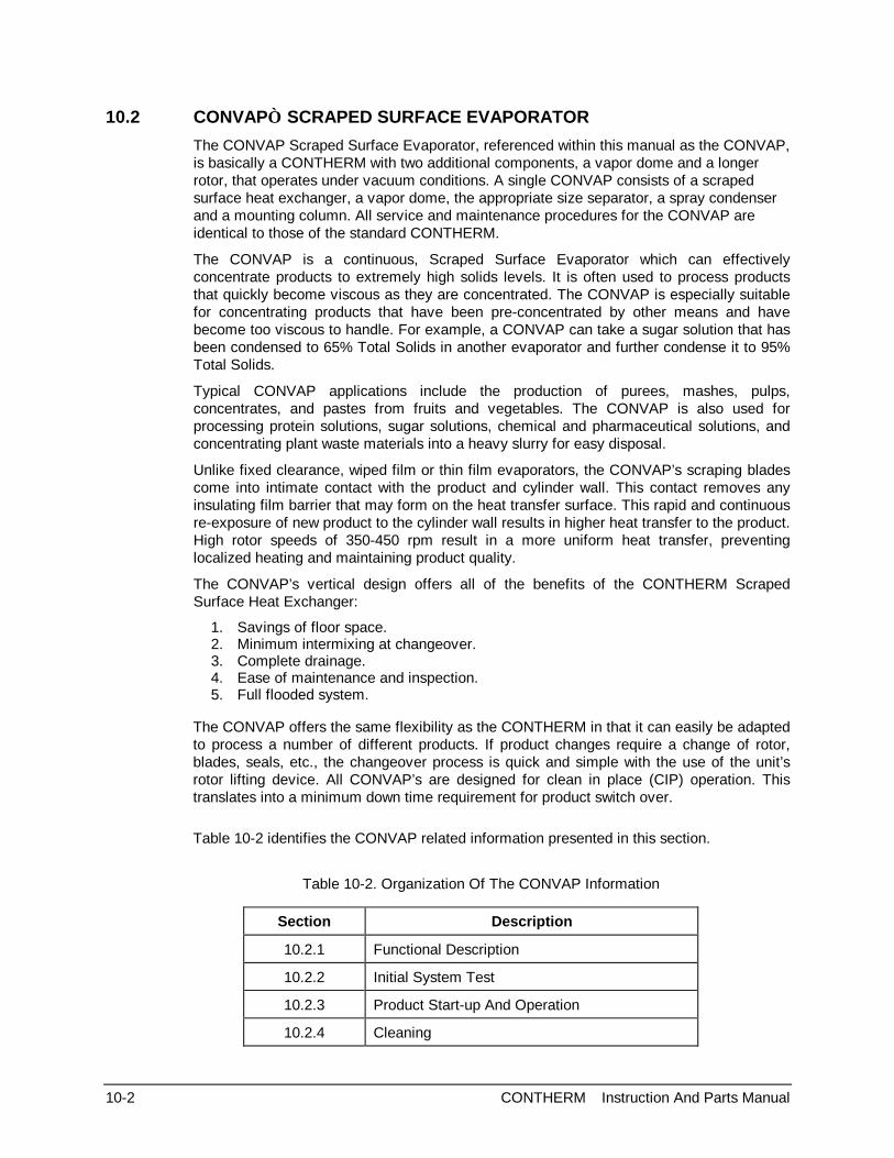


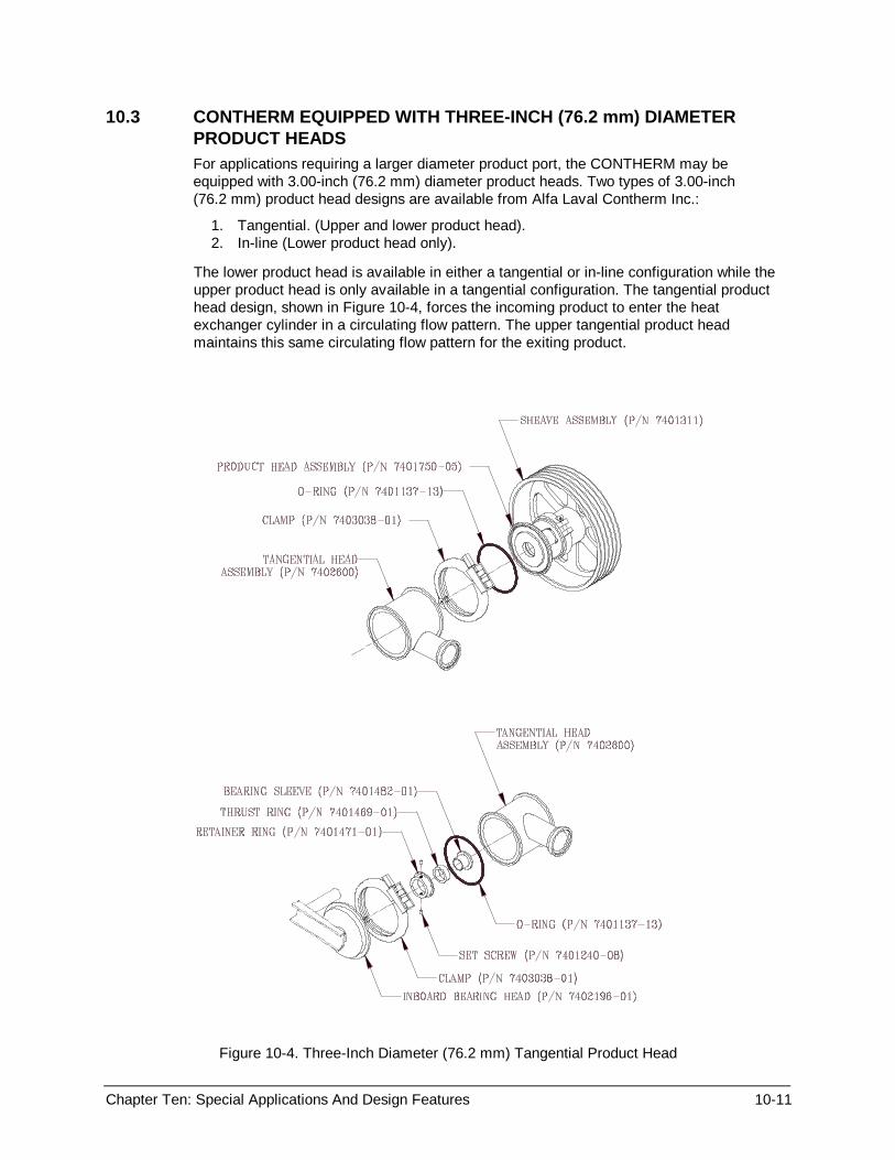
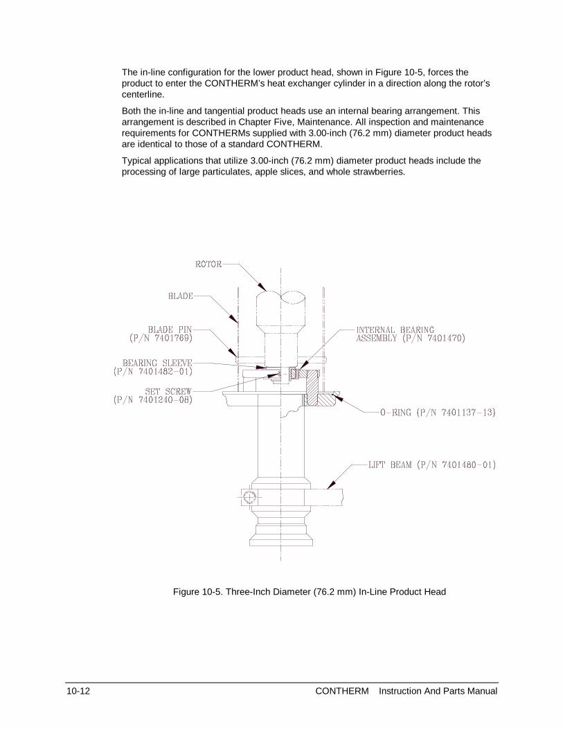


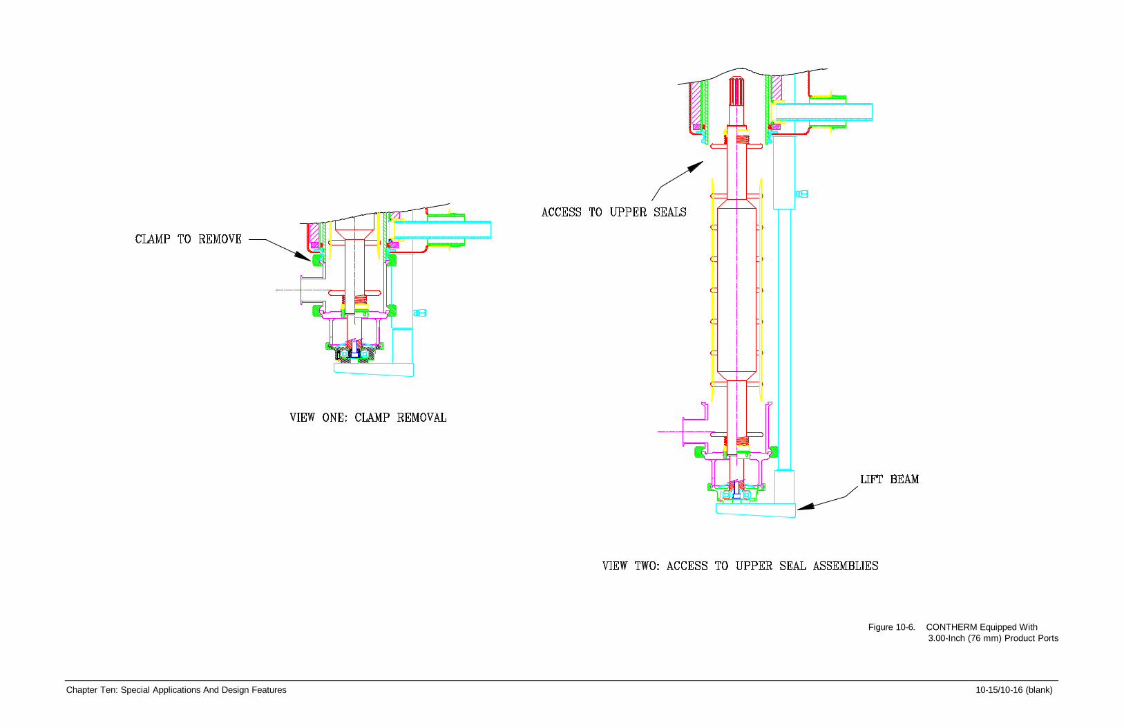


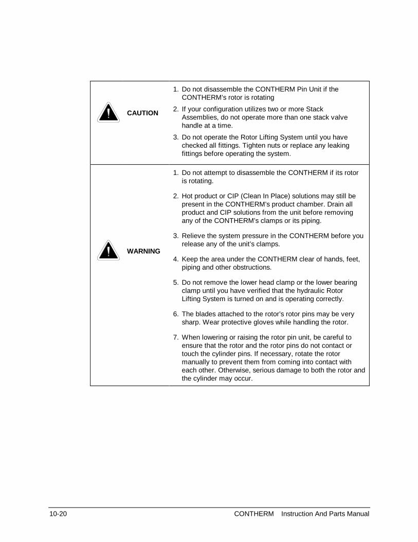

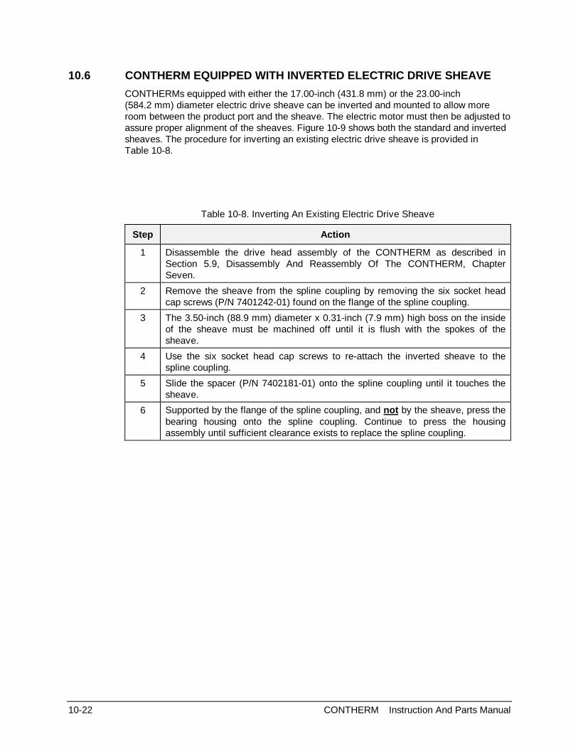


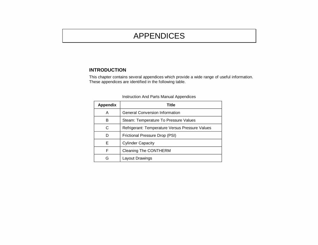


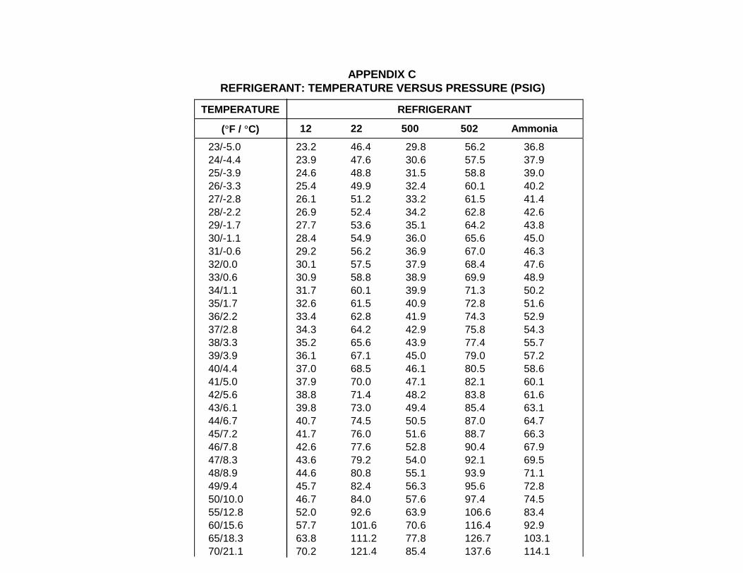


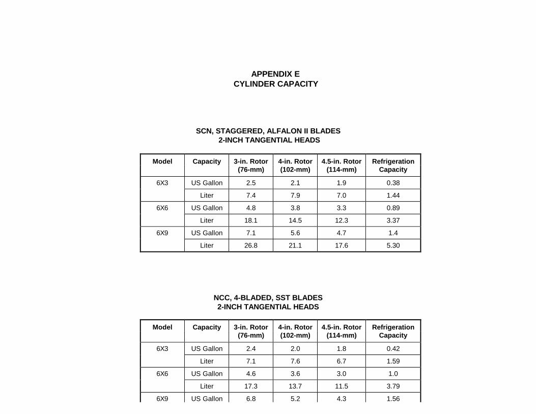


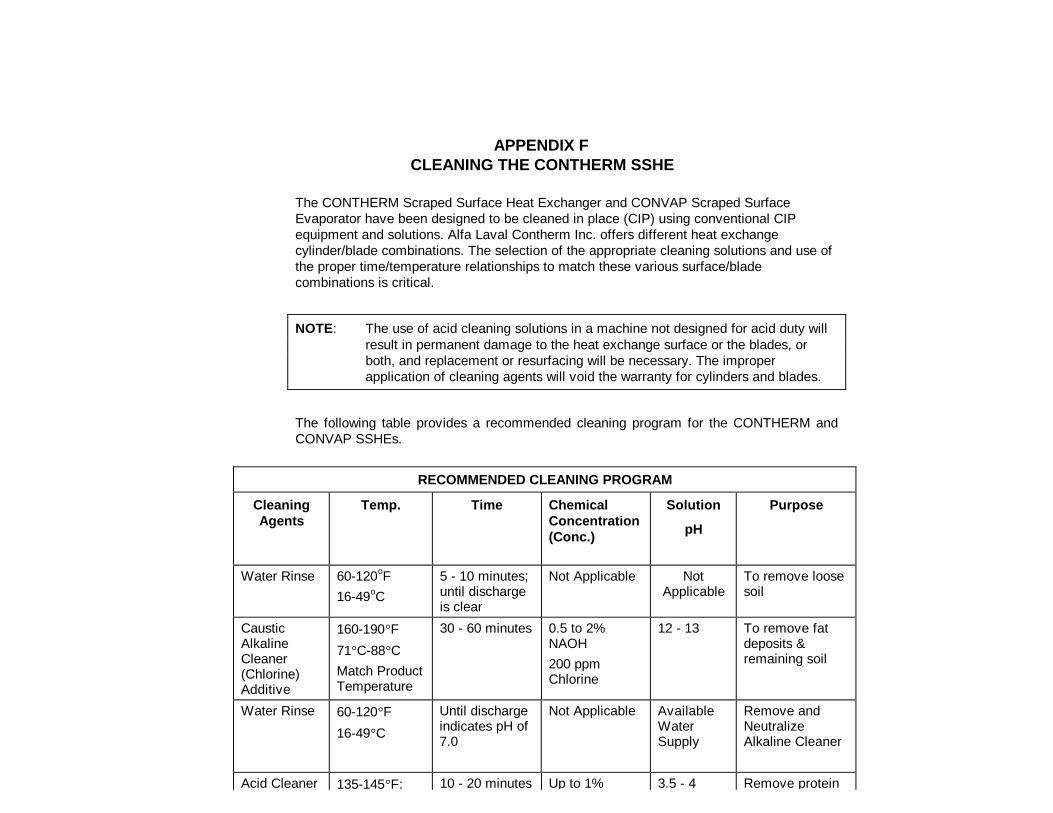


![Alfa Laval Culturefuge 400 B · Alfa Laval is a trademark registered and owned by Alfa Laval Corporate AB. [Product name] is a trademark owned by Alfa Laval Corporate AB. PCHS00142EN](https://static.documents.pub/doc/80x56/5e71a377bc5a292f26773958/alfa-laval-culturefuge-400-b-alfa-laval-is-a-trademark-registered-and-owned-by-alfa.jpg)


