REPUBLIC OF IRAQ AL-FAO GENERAL ENGINEERING COMPANY GENERAL TECHNICAL CONDITIONS AND SPECIFICATIONS BOOK -1 / 2 SPECIFICATION OF MATERIALS WORKMANSHIP OF CIVIL ENGINEERING WORKS Second Edition 2002
Transcript
REPUBLIC OF IRAQ
AL-FAO GENERAL ENGINEERING COMPANY
GENERAL TECHNICAL CONDITIONS AND
SPECIFICATIONS
BOOK -1 / 2
SPECIFICATION OF MATERIALS WORKMANSHIP OF CIVIL
ENGINEERING WORKS
Second Edition 2002
CONTENTS
BOOK 1 SPECIFICATIONS OF MATERIALS
BOOK 2 SPECIFICATIONS OF WORKMANSHIP CIVIL ENGINEERING WORKS
BOOK 3 SANITARY WORKS
BOOK 4 ELECTRICAL WORKS
BOOK 5 MECHANICAL WORKS
(HEATING, VENTILATION, AND AIR-CONDITIONING)
Explanatory Notes (I )The conditions of contract , drawings, the bills of quantities and
this general technical specification shall be read in conjunction with the particular specification. Matters referred to , shown , or described in any one of these are not necessarily repeated in any other one.
(2)Not withstanding the sub-division of this specification under
different heading , every part of it shall be deemed supplementary & complementary to every other part and shall be read together in so far as it may be practicable so to do.
(3) Where reference is made to any local national or
international standard specification then : (a)Latest edition or superseding standard or standard shall be used. (b)Where a relevant “IOS” ( Iraqi Organization Standard ) exists ,
this shall be given first priority in application. (4) Any item not covered by this specification, reference shall be
made to “IOS” or any other recognized national or international authority.
Where any specific manufacturers and proprietary names mentioned in this specification or on the associated drawings these are intended only to indicate minimum standard for type , quality or performance of plant or materials . in no case such name be regarded as mandatory or limiting to particular suppliers or manufacturers,
(6) Unless otherwise stated in this specification, all works
quantities of construction works shall be measured according, to “ standard method of measurement for building & civil engineering work “Issued by the state organization for buildings Iraq.
-2-
Book -1- Specifications of Materials CLAUSE
NOTITLE Page
NO1.1 Standard specification : 9
1.1.1 Types 1.1.2 Tests 1.1.3 Delivery and storage 1.1.4 Rejection of cement
1.2 Water 11 1.2.1 Source 1.2.2 Tests
1.3 Aggregates 11 1.3.1 Source and duality 1.3.2 Storage of aggregate 1.3.3 Sampling of aggregate 1,4 Testing of aggregate 12
1.4.1 Methods of testing 1.4.2 Grading limits
1.4.2.1 Fin aggregate 1.4.2.2 Coarse aggregate 1.4.2.3 All - in aggregate 1.4.3. Salt content 1.4.3.1 Sulphate content (so3) 1.4.3.2 Chloride content
1.5 Proportions of the Mix of structural concrete 1> 1.-5.1 General 1.5.2 Tests
1.6 Brick 16 1.6.1 Quality 1.6.2 Sampling and testing 1.6.3 Acceptance and rejection
2.1 Earthworks 372.1.1 Cleaning the site 2.1.2 Excavation 2.1.3 Filling 2.1.4 Measurement of earthworks 2.2 Foundations 41
2.2.1 General 2.2.2 Wall foundations 2.2.3 Piling 2.3 Forms shuttering and formwork 45
2.3.1 General 2.3.2 Cleaning and oiling of forms 2.3.3 Removal of forms 2.3.4 Measurement and payment 2.4 Reinforcement 47
2.4.1 General 2.4.2 Splicing 2.4.3 Concrete protection for reinforcement 2.4.4 Placing reinforcement 2.4.5 Hooks and bends 2.5 Concrete 50
2.5.1 Mixing concrete -5-
2.5.2 Consistency of concrete
2.5.3 Cube testing of structural concrete 2.5.4 Transport concrete 2.5.5 Placing of concrete 2.5.6 Concrete face work 2.5.7 Curing of concrete 2.5.8 Measurement and payment 2.6 Masonry work 53
2.6.1 General 2.6.2 Brickwork - Embedded components 2.6.3 Brickwork - laying 2.6.4 Brickwork- facing work 2.6.5 Brickwork - bond 2.6.6 Brickwork-Extra labours 2.6.7 Brick in cement reinforced partitions 2.6.8 Brick in cement partitions 2.6.9 Measurement of masonry 2.7 Plastering 55
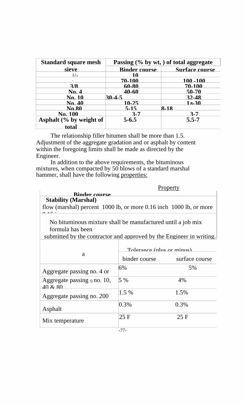
2.15 False ceiling 67 2.15.1 Acoustic ceiling tiles 2.15.2 Asbestos 2.15.3 Hy- rib 2.16 Road Construction 68 2.16.1 General 2.16.2 Sampling and Testing 2.16.3 Equipment 2.16.4 Stockpiling 2.16.5 Weather Limitation 2.16.6 Subbase course 2.16.7 Grade and Alignment control 2.16.8 Base courses
2.16. 9 Concrete slabs 2.16.10 Bituminous prime coat 2.16.11 Bituminous Tack coat 2.16. 12 Bitumin stabilized sand and Gravel Base. 2.16.13 Hot Mix Asphaltic concrete pavement 2.16.14 Pavement and Footways of Precast concrete flags. 2.16.15 Concrete curbs, channels and quadrant. 2.16.16 Opening to traffic and maintenance. 2.16.17 Measurement and payments
-8-
1.1:- STANDARD SPECIFICATIONS : Except where otherwise specified all materials and workmanship
shall conform to the requirements of the relevant National Iraqi Standards (IQS) specifications . Other equivalent standards specifications (BS , ASTM) may be substituted for the Iraqi Standards with the approval of the Engineer .
The Contractor shall obtain and keep on Site at least one copy of each (IQS) or other approved Standards which is referred to in the specifications , and in addition , shall keep on Site any (IQS)or other Standard which applies to materials which are being supplied to , or workmanship which is being executed on, the work.. The cast of this is deemed to be included in the prices and no separate payment will be made to the contractor in this respect . 1.2: QUALITY OF MATERIALS :
All materials shall be new and unused , of standard first grade quality , and of the best workmanship and design.
Before procurement, the contractor shall furnish to the Engineer, for his approval, the names of the manufacturers of all materials and equipment , which he intends to use on the works . samples of materials shall be submitted to the Engineer, for his approval , when so directed . Materials and equipment used or installed on the works, without the approval of the Engineer shall be liable to subsequent rejection . The Engineer shall deter nine whether all or any of the materials offered or delivered for use in the works is suitable for the purpose and the Engineers decision in this respect shall be find and conclusive. CEMENT 1.1.1 :- TYPES :
Portland cements shall comply in all respects with the requirements of the IQS 51984 , Other cements should comply the requirements that specified by the Engineer. The Engineer could make use of any adopted standards such as :
BSIZ -1989 , BS4027 - 1980, and ASTM C150 - 97 in specifying any additional requirements which are not specified by the IQS 5 - 1984 . 1.1.2 :- TESTS :
The contractor shall submit to the Engineer , without charge , test certificates relating to each consignment of cement . Each certificate shall show that a sample of the consignment has been tested by the manufacturer or by an approved laboratory and that it complies in all respects with the requirements of the adopted specifications . When required by the Engineer, the contractor shall supply samples of cement taken on delivery to or during storage on the site , for testing at a nominated laboratory.
No cement from any consignment shall be used without the approved of the Engineer and the contractor shall maintain a record forth locations of concrete made from each consignment such records shall be available for inspection by the Engineer.
-9-
All cement shall be delivered to the site in properly marked ( with date of delivery ) sound and sealed paper bags or other approved containers , unless written approval from the Engineer shall be obtained for the handling for cement in bulk . Cement shall be delivered in quantities , sufficient to ensure the proper progress of the works and the quantities held in stock on site shall be to the approval of the Engineer .
If storage bins are used , there shall be sufficient bins to differentiate between each months deliveries . storage bins shall be so constructed that there is no dead storage . cement which has been at site for (60 ) sixty days or more shall be used before using cement which has been at site for a lesser period No cement shall be used which has been at site for more than ( 6) six months or which , in the opinion of the Engineer, may have deteriorated in any way until it has been thoroughly and newly tested .
Bagged cement shall be stored in a weather - proof and reasonably air -tight places provided solely for that purpose . The floors of the storage places shall be raised above the ground level to prevent the absorption of moisture . Bagged cement shall not be stored more than ( 7) seven bags height for periods longer than ( 30 ) thirty days .
Each consignment of cement shall be stored separately so as to provide easy access for inspection and testing . After they have been approved by used in the order in which they were delivered . 1.1.4:- REJECTION OF CEMENT:
Not with standing the receipt of the test certificate required by clause ( 1.2 ), the Engineer may reject any cement as a result of further tests . The Engineer may also reject cement which has deteriorated owing to inadequate protection or other causes or in any other case where the cement is not to his satisfaction .
The contractor shall remove all rejected cement from the site without delay .
1.1.5:- SPECIAL REQUIREMENTS : a) The sulphate resisting portland cement shall be used for all
concrete works that are in contact with soil or under ground water (containing sulphates ), although that was not specified in the drawings or the bills of quantities .
b) The alkali content of cement shall be calculated according to the ASTM C 150 -97 , equiralant sodium oxide , as follows : Na2 Oequ. = o.658k20 + Na20 The alkali content shall not exceed 0.6 %.
c) If the alkali content of cement is greater than 0.6 %, tests shall be carried out according to IQS 42 - 1984 with the aggregate to be used prior to approving the use of the cement .
d) Any other types of cement shall comply the requirements of the IQS 5 - 1984 or the requirements of any adopted standard, approved by the
Engineer.
-10-
1.2.1 SOURCE ; The water for washing aggregates , mixing concrete and mortar ,
and for curing shall be from an approved source and shall contain no deleterious matter which significantly affects the setting time or strength or durability of the concrete or which has any effect on the appearance of the hardened concrete by discoloration of efflorescence . If required by the Engineer , the contractor shall without extra charge treat the water taken from rivers , canals , or from any other sources to such a degree as maybe necessary from any other sources to such a degree as may be necessary in order to render it suitable for mixing concrete and mortar . 1.2.1 :- TEST
The water used for all purposes shall comply with the IQS 1692-1988 requirements. The Engineer could make use of the recommendations in the Appendix to the BS-3 1481980 for specifying any requirement that Is not found in the IQS1692-1988.
The Contractor shall deliver to the Engineer , without charge samples of the water proposed for use on the works , for toting to confirm its Suitability . samples may be delivered sufficiently in advance of the work for completion of the tests , before the water is required for use and at such other times during .
The course of the contractor as the Engineer may direct . AGGREGATES 1.3.1 SOURCE AND QUALITY ;
Aggregates for concrete and mortar shall be obtained from an approved source , and shall conform with the requirements of IQS 45-1984 .
Aggregates (fine and coarse)shall be natural or crushed stone or crushed gravel provided that the gravel contains no flint or chert. Particles shall be clean and free from adherent impurities in excess of limits laid down in IQS 45-1984 nor shall it contain laminated materials , shales and other porous or fragile particles , soluble matter , sulfates , alkalis , or other deleterious materials in such a form or in such quantities as to affect adversely the quality of concrete . 1.3.2 STORAGE OF AGGREGATE :
The contractor shall provide means of storing the aggregate at each point where concrete is made such that : a) Contamination of the aggregates by the ground or other
foreign matter shall be effectively prevented at all tines . b) Each heap of aggregate shall be capable of drawing freely
Wet aggregate shall not be used unit \ in the opinion of the Engineer it has drained to a constant and uniform moisture content , unless the contractor measures the moisture content of aggregate continuously and adjusts the amount of aggregate and added water in each batch of concrete mixed to allow for the water contained in the fine aggregate .
-11-
Sampling shall be carried out as required by the Engineer in accordance with requirements of the IQS 29-1984. Samples shall be of a size, sufficient to carry out all tests which the Engineer may order or as shown in Table 4.3.1. After approval has been given for any particular aggregate , a sample , weighing at least (50)fifty kilograms of the approved aggregate shall be retained by the Engineer as a standard against which all future samples shall be compared.
TABLE 4.3.1:MINIMUM WEIGHTS OF AGGREGATE SAMPLES FOR TESTING.
Maximum size of aggregate,Mm
Weight of sample, kg
? 25 505-25 25? 5 13
1. 4 TESTING OF AGGREGATE : 1.4. - METHODS OF TESTING :
During the course of the contract , fine and coarse aggregates shall be tested as often as required by the Engineer . Tests shall be carried out in accordance with the methods stated in the standards shown in table 4.2.1 otherwise ordered by the Engineer
TABLE 1.4.1: TESTS OF AGGREGATE AND RELEVANT STANDARDS
Test Method of test 1. Particle size IQS 30-19842. Moisture content IQS 32-19883. Materials finer then 75 Mm sieve IQS 33 - 19894. Organic impurities content IQS 33 - 19895. S03 content IQS 33 - 19896. Chloricle content Iraqi Reference Guide 368-19907. Alkali reactivity IQS 42 - 1989
1.4.2. GRADING LIMITS : 1.4.2.1. FIN AGGREGATE :
The grading fine aggregate for concrete and mat-tar shall be within the limits , shown in table 1.4.2.1 , that specified by the IQS 45-1984 .
-12-
Sieve size, mm Percentage Passing by weight ; Zone 1 Zone 2 Zone 3 Zone 4
1.4.2.3 ALL- IN AGGREGATE : The grading of an all-in aggregate , when angylesed as described lin
IQS 45-1984 , shall be in accordance with table 1.4.2.3 . The use of all-in aggregate may, with the approval of the Engineer , be permitted in the case of mass concrete .
-13-
Sieve size, mm Percentage Passing (mass) 40mm,nominal size 20mm,nominal size
The sulphate content (S03) of aggregate for concrete and mortar shall not exceed the limits , shown in table 1.4.3.1 , that specified by the IQS 45-1984.
TABLE 1.4.3.1: SULPHATE CONTENT IN FINE AGGREGATE
AND CONCRETE
Maximum S03content Part of the structure n fine In concrete mixes(for all ingredients)
Cement content kg/m3
S03 %by wt of Cement
Group One a. Reinforced concrete for > 300 4.0 b. Members are in contact with 250-300 4.5 b. Prestressed concrete except 0.5 < 250 5.0
(types shown in Group two-0)
Group Two a. All reinforced and plain concretes > 300 4.0
that were not mentioned in Group 0.75 250-300 4.5one(a,b). < 250 5.0
b. Concrete flags and tils . Prestressed concrete cured with steam and is not in contact with
Group Three ment -sand mortar 0.75 - 6.0
Group Four a. Temporary building concrete 1.0 - 6.0
(with , Useful life not more than 10
years) b. Concrete blocks
I,
-14-
No concrete shall contain more than the total chloride content (as chloride ions) expressed as percentages by weight of cement , shown in table 1.4.3.2
TABLE 1.4.3.2: MAXIMUM ALLOWABLE CHLORIDE CONTENT
Type of member Maximum water soluble chloride ion (CL`) in
concrete , prevent by weight of cement
a. Prestressed concrete . 0.06 b. Reinforced concrete exposed to chloride in 0.15
Service . c. Reinforced concrete that will be dry or 1.00
protected from moisture in service d. Other reinforced concrete construction . 0.30
REF : ACI 318 - 95
ADMIXTURES
1.5.1 GENERAL Admixtures are material added to the concrete
materials during mixing for the purpose of altering the properties of the fresh or hardened concrete .
Admixtures shall only be used if the Engineer has given his prior approval in writing. Both the amount added and the method of use shall be to the approval of the Engineer who shall also be provided with the following information: 1. The typical amount added and the detrimental effects , if any , of an increase or
Decrease in this amount . 2. The chemical name (s) of the main active ingredient (s) in the admixture . 3.If the admixture is chloride - free or not .
Admixtures containing calcium chloride shall not be used under any condition
1.5.2: TESTS : Any approved admixture shall conform to whichever of the
following standards is appropriate : a) Air-entraining admixtures (IQS 2031 -1996) . b) Water - reducing admixtures (ASTM C494-1990) c) High - range water - reducing admixtures (ASTM C494-1990) d) Pozzolanic materials used as mineral finely divided admixtures (IQS 3021-1990)
When more than one admixture is used in a concrete mix the compatibility of the various admixtures shall be ascertained by standard tests and certified by the manufacturers . Admixtures shall always be used in accordance with the manufacturer's instructions .
-15-
1.6.1 QUALITY : Brick shall be of the best quality available , manufactured by any
well - known and approved process . They shall be mechanically processed and properly burnt . Bricks shall conform to the requirements of IQS 25 - 19 . 1.6.2 SAMPLING AND TESTING :
Sampling of brick shall be down according to the IQS 24 -19 with the sample size specified by this standard . Samples shall be submitted to the Engineer for his approval and any consignment delivered to the work shall conform to the quality of samples approved by the Engineers .
Testing of brick shall be carried out according to IQS24-19 and shall conform the requirements of IQS 25-19 . 1.6.3 ACCEPTANCE AND REJECTION :
In advance the brick shall : a) Have sharp edges . b) Be well burnt (unburnt brick shall never be permitted to be used on works ) c) Be free of any cracks . d) Be free of any gypsum and salts .
Otherwise , the Engineer has the right to reject any consignment that fails to possess
the aforementioned properties . CONCRETE BLOCKS 1.7.1 QUALITY
Concrete (hollow or solid) blocks shall be of best quality available , manufactured by a well- known approved process . They shall be manufactured mechanically by both pressure and vibration . Blocks shall not be used with age less than (7) seven days from the date of manufacturing . 1.7.2 TESTING :
Tested blocks shall conform the requirements of IQS 1077 - 1985 .
ORDINARY AND TERRAZZO TILES 1.8.1 QUALITY :
Tiles that are used in flooring of buildings shall be of best available quality . Ordinary and terrazzo tiles shall be manufactured mechanically .
1.8.2 SAMPLING AND TESTING : Sampling of tiles shall be down according to the IQS 1042 , 1043
for terrazzo and ordinary tiles respectively . Testing of tiles shall comply the requirements of IQS 1042 - 1043 - 1984 .
-16-
CONCRETE FLAGS 1.9.1 QUALITY
Concrete flags that are used for roofing of building or for finishing sidewalks shall be of best available quality They shall be manufactured by pressure or vibration or both.
These flags shall not be used with age less than [7] seven days from the date of manufacturing . 1.9.2 SAMPLING AND TESTING :
Sampling shall be taken by the Engineer randomly according to the method specified by the IQSl 107-1987 and with sample sizes specified by this standard .
Testing shall be carried ont according to the IQS1107-1987. Test results shall conform to the requirement of IQS 1107-1987. JUSS 1.10.1 QUALITY :
The juss used shall be factory product and shall be of the ordinary type , hot and well burnt . The juss shall be clean , free of any foreign matter , and the contractor shall take necessary measures to protect the juss during transportation and storage from rain humidity and other factors which are likely to cause damage to it .
1.10.2 SAMPLING AND TESTING : Sampling of juss shall be down in accordance with the IQS 28-1989
, by the Engineer . Testing shall be carried out according to the methods specified by
IQS27-1989 . Test results shall comply the requirements of IQS 28-1989 . 1.10.3 ACCEPTANCE AND REJECTION :
If it is found that the supplied juss or part of it is exposed or damaged by rain or humidity and become cold and inferior, then such juss shall not be used in the work and the contractor shall remove it from the site , at his own expense .
STRUCTURAL STEEL 1.11.1 GENERAL
The grades of structural steel approved for use under most building codes and mainly covered by ASTM standard specification , extend to a yield stress of 100 (690 MPa) . Some of these ASTM standards specify a minimum yield point, while others specify a minimum yield strength . the term " yield stress" is used in the specification as a generic term to denote either the yield point or the yield strength. it is important to be aware of limitations of availability that may exist for some combinations of strength and size not all structural section sizes are included in the various material specifications . for example, the 60 (415 MPa) yield strength steel in the A572/A572M-99 specification includes plate only up to 1.25 in (32 mm) in thickness . another limitation on availability is that even when a product is included in the specifications. it may be in frequently produced by the mills . specifying these
-17-
from the mills . consequently it is prudent to check availability before completing the details of a design .
Properties in the direction of rolling are of principal interest in the design of steel structures hence , yield stress as determined by the standard tensile test is the principal mechanical property recognized in the selection of the steels approved for use under the specification . it must be recognized that other mechanical and physical properties of rolled steel,such as anisotropy,ductility,notch toughness,formability,corrosion resistance,etc.,may also be important to the satisfactory performance of a structure.steel conforming to one of the following standard specifications is recommended for use in steel buildings:
a)Carbon structural steel,ASTM A36/A36M-97a b)Pipe,steel,black and hot-dipped,zinc coated welded and seamless
d)Cold-farmed welded and seamless carbon steel structural tubing in
rounds and shapes,ASTM A500-99. f) Mot-formed welded and seamless carbon steel structural tubing,ASTM 501-99 . g)High-yield-strength,quenched and tempered alloy steel plate,suitable for welding,ASTM AS4/AS4 M-94a
h)High-strength carbon-manganese steel of structural quality,ASTM A529/A529M-96 i)Steel,sheet and strip,carbon,hot rolled,structard quality,ASTM A570/A570M-98 gr.40 (275),45 (310),and 50(345). j)High-strength low-alloy structural steel with SOksi (345 MPa)min . yield point to 4in (100mm) thick,ASTM A588/A588M-97a
1)Steel,sheet and strip,high-strength,low-alloy,hot rolled and cold-rolled with improved atmospheric corrosion resistance,ASTM A606-98.
m)Steel,sheet and strip,high-strength,low-alloy,columbium or vauadium,or both,hotrolled and cold-rolled,ASTM A607-96.
n)Hot-formed welded and seamless high-strength low-alloy structural tubing,ASTM A618-99.
o)Carbon and high-strength low-alloy structural steel shapes,plates and bars and quenched-and-tempered alloy structural steel plates for bridges,ASTM A709/A709M-97b.
p)Cold-formed welded and seamless high-strength low-alloy structural tubing with
improved atmospheric conosior resistance,ASTM A847-99a q)Quenched and tempered low-alloy structural steel plate with (70) ksi (485 MPa)
minimum yield strength to (4) inches (100mm) thick,ASTM A852/A852M-97. r)High-strength low-alloy steel shapes of structural quality,produced by quenching and
self-tempering process (qst), ASTM A913/A913u1-97/ s)Steel for structural shapes for use in building framing,ASTM A992/A992M-98 t)Structural steel supplies to bs4360,(,rode (43),a,b and c,grade (50),b and c,grade (55), c.
-18-
1.11..2 STRUCTURAL STEEL IN COMPOSITE MEMBERS: Structural steel used with reinforcing bars in composite compression members meeting the requirements of ACI-building code, committee 318-1999, shall conform to one of the following specifications: a)Specification for structural steel, ASTM A3 6M-94. b)Specification for high-strength low-alloy structural STEEL,ASTM A?4?M-93a. c)Specification for high-strength low-alloy columbium-vanadium steels of structural quality, ASTM AS72M-94b. d)Pecification for high-strength low-alloy structural steel with (50) ksi
(345 MPa) minimum yield point to 4inches(100mm)thicle, ASTM
A588M-94_ 1.11.3 UNIDENTIFIED STEEL:
a)Strength corresponding to BS 4360,grade (43) steel may be adopted where no other information is available .
b)Unidentified steel, if surface conditions are acceptable according to criteria contained in ASTM A6/A6M-2000,is permitted to be used for un important members or details, where the precise physical properties and weldability of the steel would not affect the strength of the structure.
1.11.4 HEAVY SHAPES :
The web-to-flange intersection and the web center of heavy hot-rolled shapes as well as the interior portions of heavy plates may contain a coarser grain structure and/or lower toughness material than other areas of these products.
When heavy cross sections are joined by splices or connections using complete joint-penetration welds which extend through the coarser and/or lower notch-tough interior portions, tensile strains induced by weld shrinkage may result in cracking, for example in a complete-joint-penetration welded connection of a heavy cross section beam to any column section. when members of lesser thickness are joined by completejoint-penetration welds, which induce smaller weld shrinkage strains, to the finer grained and/or more notch-tough surface material of ASTM A6/A6M-2000 group (4) and (s) shapes and heavy built-up cross-sections, the potential for cracking is significantly lower, for example in a complete-joint-penetration groove welded connection of anon-heavy cross-section beam to aheavy cross-section column .
For critical applications such as primary tension members, material should be specified to provide adequate toughness at service temperatures. because of differences
-19-
experienced in actual structures,the (cnv) test is shown below, fig. (11 .4.1) .
CVN specimen 10 action
Fig.location from which charpy impact (11.4.1) specimen shall be taken for ASTM A6/A6M-?OOO,group (4) and (5) rolled shapes to be used as
members subject to primary tensile stresses due to tension or flextUre,and to comply with the alsc (lrfd) design specification for structural steel buildings (september,4,2001),toughness need not be specified if splices are made by bolting. if such members are spliced using complete-joint-penetration groove welds, the steel shall be be specified in the contract documents to be supplied with charpy v-notch (CVN) impact testing in accordance with ASTM A6!A6v1-?OOO,supplement any requirements (S5). the impact test shall meet a minimum average valve of (20) ft-ibs (?7j) absorbed energy at +70 f(+?/?) and shall be conducted in accordance with ASTM A673/A673-95.
For plates exceeding two inches (50mm) thick used for built-up cross-sections with bolted splices and subjected to primary tensile stresses due to tension or flexure,material toughness need not be specified.
If such cross-sections are spliced Using complete-joint-penetration welds, the steel shall be specified in the contact documents to be supplied with charpy v-notch testing in accordance with ASTM A6/A6M-2000.
Supplementary requirement (S5) . the impact test shall be conducted by the procedure in accordance with ASTM A673/A673M-95.
Frequency (p), and shall meet a minimum average valve of (20) ft. ibs (27j) absorbed energy at (+70)f (+?/c) . 1.1 L5 STEEL CASTINGS AND FORGINGS:
Steel castings and foraings may be used for components in bearings and other similar parts,as allowed by bs5950:partl : 1985 cast steel shall conform to one of the following standard specifications : a)Steel castings, carbon, for general application,ASTM A27/A27M GR.65-35 (450-240).-95 b)Steel castings,high strength,for structural pLirposes.ASTM A
148/148M GR.80-50 (550-345)-93b . c)Steel castings should comply with BS 3100 steel fargings shall conform
to the following standard spefication . i.Stee1 for2ings shall comply with BS29.
certified test reports shall constitute sufficient evidence of conformity with standards
-20-
1.11.6 BOLTS, WASHERS, AND NUTS Steel bolts, washers and nuts shall conform to one of the following standard specifcations.to-ether with (aisc,lrfd) design specification for structural steel buildings (sep.4TH ,2001) and BS 5950: partl,code of prachee for structural use of steel work in building (1985). a)Carbon and alloy steel nuts for bolts for high-pressure or high-
temperature service,or both, ASTM A 194/A 194M-98b. b)Carbon steel bolts and studs,60000psi tensile strength,ASTM A307 (grade a& b)-97. c)Structural bolts,steel,heat treated,( 1?0-105)ksi minimum tensile strength,ASTM A325-97 . d)High strength bolts for structural steel joints [metric] , ASTM A3?SM-97. e)Quenched and tempered steel bolts and studs, ASTM 449-93. f)Heat-treated steel structural bolts. l 5Oksi minimum tensile strength,ASTM A490-97. g)Hi-h-strength steel bolts,classes (10.9) and (10.9.3),for structural steel joints (metnic),ASTM A490M-97. h)Carbon andalloy steel nuts,ASTMAS63-97. i)Carbon and alloy steel nuts [metric] ASTM AS63M-97. k) Hardened steel washers[metric], ASTMF 436M-93. 1)Compressible-washer-type direct tension indivators for use with
structural fasteners,ASTM F959-96. m)Compressible-washer-type direct tension indicators for use with
structural fasteners [metric].ASTM F959M-96. n)"Twist off" type tension control structural bolt/nut/washer
assemblies,steel,heat treated,(1?0-105)ksi minimum tensile stren~th, o)Bolts and nuts should comply with bs 4190 or bs 3692 . p)Countersunk or cupheaded bolts should comply with bs 4933. q)High strength friction grip bolts complying with bs 4395 may be used untorqued r)Washers may comply with bs43?0. s)Hi~h strength friction grip bolts and associated nuts and washers may comply with bs 4395 with minimum shank tensions specified in bs 4604 .
Manufacturer’s certification shall constitute sufficient evidence of conformity with the standards.
1.11.7 ANCHOR RODS AND THREADED RODS:
Anchor rods and threaded rod steel shall conform to one of the following standard specifications: a)Carbon structural steel/ASTM A36/A36M)-97a. b)Alloy steel and stainless steel bolting materials for high temperature service ASTM A19-')/A19')' M-99 .
c)Quenched and tempered alloy steel bolts; tads and other externally threaded fasteners. ASTM A354-98 .
e.) High- strength low-alloy structural steel with (50) ksi [345 MPa] minimum yield point to 4 in [100mm] thick,ASTM A588/A588-97a. f)Anchor bolts,stee1,36,55 and 105 ksi yield strength,ASTM F1554-99. g)Specification for carbon and Law-Alloy steel Electrodes and Fluxes for
Electrolong welding, AWS AS.25 / AS.25 M-97. h)Specification for carbon and Law-Alloy steel Electrodes and Fluxes for
Electrolong welding, AWS AS.26 / AS.26 M-97. i)Specification for carbon and Law-Alloy steel Electrodes and Fluxes for
Electrolong welding, AWS AS.28- M-96. j)Specification for Law-Alloy steel Electrodes for Fluxes cored Arc
The filler metal specification , listed above . are general and include
filler metals suitable for building construction , as well as consumable that would not be suitable for building construction . For example , some electrodes covered by the specifications are specifically limited to single pass applications , while others are restricted to sheet metal applications . Many of the filler metals listed are "low hydrogen” that is , they deposit filler metal with low levels at diffusible hydrogen. Other materials are not . Filler metals listed . Manufacturer's certification shall constitute sufficient evidence of
conformity with the standards . The designer should be aware that pretensioning of anchor rods is not recommended due to relaxation and the potential for stress corrosion after pretensioning
shielding gas , etc...) should comply with BS5135 , or shall conform to one of the following specifications of the American Welding society : a. Specification for carbon steel Electrodes for Shielded Metal Arc welding , AWS AS. I-91. b)Specification for Law-Alloy steel Electrodes for Shielded Metal Arc welding, , AWS AS.5-96.
c)Specification for carbon steel Electrodes and Fluxes for sub merged Arc welding , AWS AS. 17/ AS. 17 M-98.
d)Specification for carbon steel Electrodes and pads for Gas Shielded Arc welding , AWS AS. 18-93.
e)Specification for carbon steel Electrodes for Fluxes cored Arc welding , AWS AS.20 -95 '
f)Specification for carbon and Law-Alloy steel Electrodes and Fluxes for submerged Arc welding, AWS AS.23 / AS.23 M-97.
Under the various AWS AS Specification may or not have required impact toughness depending on the specific electrode classification.
Engineers do not , in general , specify the exact filler metal to be employed on a particular structure . Rather, the decision as to which welding process and which filler metal is to be utilized is usually left with the fabricator or erector. To ensure that
-22-
I
1.11.9 SHEAR CONNECTORS Steel stud shear connectors shall conform to the requirements of
structural welding code-steel, AWS D1.1-2000. Shear connectors shall be headed steel stands. With a minimum head
diameter of (1.5d) and a minimum depth of head of (O.4d) where (d) is the nominal shank diameter of the stand , and not less than four stnd diameters in length after installation , or hot rolled steel channels.
Shear connectors shall be embedded in concrete slabs made with ASTMC33-97 aggregate or with rotary Kiln produced aggregates conforming to ASTMC330-97, with concrete unit weight not less than 90 pcf (1440 kg/m3).
The stnd material should be mild steel with minimum properties (in the cold drawn condition), when tested in accordance with BS18 , and conforms with BS5950 :part 3-1 , as follows : ultimate tensile strength : 450 N/mm2 elongation :15% (on 5.65? 50 gang length , as given in BSI 8).
Where other types of shear connectors are used , structural steel used for fabricated shear connectors should comply with grades 43,50 or WR5O of BS4360
Friction grip bolts used as shear connectors with BS4395: part 1 . Other materials may also be used for shear connectors provided that
they can be demonstrated to produce shear connectors possessing sufficient deformation capacity . 1.11.10 PROFILED STEEL SHEETS
The steel used to manufacture the profiled steel sheet , as required by the BS5950 : part4 , should have a specified yield strength of not less them (220)N/ mm'- and be in accordance with BS 1449: part1 or BS2989 other steels of similar quality material may be used .
Zinc coating , if specified , should comply with the requirements of BS2989. The type C coating (275 g/ m2 total including both sides) is normally specified for internal floors in a non-aggressive environment , but the specification may be varied depending on service conditions .
The exposed surface , i.e.. the underside of the profiled steel sheet , should be adequately protected to resist the particular atmospheric conditions including those arising during site stroing and erection . Reference should be made to dd24 and BS5493 for the recommended protective systems . 1.11.11 STEEL PIPE OR TUBING
Steel pipe or tubing for composite compression members composed of a steel encased concrete core meeting requirements of the ACI-building code , committee 318-1999 , shall conform to one of the following specifications . a)Specification for pipe , steel , black and hot-dipped , zinc-coated welded and seam
less , grade(B) ,ASTM AS3 -93a . b)Specification for Cold-formed welded and seam less carbon steel
structural tubing in rounds and shapes , ASTM A500-93 . -23-
c.) specification for Hot-formed welded and seamless carbon steel structural tubing, ASTM A501-93 STEEL REINFORCEMENT 1.12.1 GENERAL
Reinforcement shall be deformed reinforcement , except that plain reinforcement shall be permitted for spirals or tendons , and reinforcement consisting of structural steel, steel pipe , or steel tubing shall be permitted as specified in sections (A.2) and (A.11) of this specification .
Other metal elements , such as inserts , anchor bolts , or plain bars for dowels at isolation or contraction joints , are not normally considered to be reinforcement under the provision of ACI-building code , committee 318-1999 . 1. 12.2 WELDED REINFORCEMENT
Welding of reinforcing, bars shall conform to the structural code , rein forcing steel, ANS 1/AWS D 104 of the American welding society .
ASTM rein forcing bar specifications , except for ASTM A 706N1-95 shall be supplemented to require a report of material properties necessary to conform to the requirements in ANSI /AWS D 1.'1 .
Weldability of the steel is based on its chemical composition or carbon equivalent(CE). (CE) is calculated from the chemical composition of the rein forcing bars using formulas given for bars other than ASTM A 706M -96a. Material , and for ASTM A 706 M -96a bars . The engineer should realize that the chemical analysis for bars other than A706M-96a , required to calculate the carbon equivalent is not routinely provided by the producer of the rein forcing bars. Hence , for welding rein forcing bars other than A706M -96a bars , the design drawings or project specifications should specifically require results of the chemical analysis to be furnished .
The ANS UAWS D1.4 welding code requires the contractor to prepare written welding procedure specifications conforming to the requirements of the welding code The welding code ANS1/AWS D1.4 requires a minimum preheat for a weld to existing rein forcing bars in a structure with undefined chemical composition .
For welding of wire to wire , and of wire to rein forcing bars or structural elements the engineer should specify requirements or performance criteria for this welding .
Machine and resistance welding as used in the manufacture of welded wire fabrics is covered by ASTM A185-9=1 and ASTM A497 - 9=1a . 1.12.3 DEFORMED REINFORCEMENT
Deformed reinforcing bars shall conform to one of the following specifications: a. specification for deformed and plain Billet -steel bars for concrete reinforcement . ASTM A 615M -96a.
b. specification for rail-steel deformed and plain bars for concrete reinforcement
including supplementary requirements S1-ASTM A616M -96a . c. specification for axle-steel deformed and plain bars for concrete reinforcement ,
ASTM A617M-96a. -24-
e. Bar masts for concrete reinforcement shall conform to specification for fabricated
deformed steel bar mats for concrete reinforcement , ASTM A l 84M-90 .
f. Deformed wire for concrete reinforcement shall conform to specification for steel
wire , deformed for concrete reinforcement , ASTM A496-94 . g. Welded plain wire fabric for concrete reinforcement shall conform to the
specification for steel welded wire fabric , plain , for concrete reinforcement ASTM A 185-94.
h. Welded deformed wire fabric for concrete reinforcement shall conform to the specification for steel welded wire fabric , deformed for concrete reinforcement , ASTM A497-94a.
i. Galvanized reinforcing bars shall comply with the specification for Zinc-coated steel bars for concrete reinforcement ASTM A76M-90.
j. Epoxy - coated reinforcing bars shall comply with the specification for Epoxy - coated reinforcing steel bars ASTM A775M-94d . or with the the specification for Epoxy - coated prefabricated steel reinforcing bars , ASTM A934M-95.
k. Epoxy - coated wires and welded wire fabric shall comply with the specification for Epoxy - coated steel wire and welded wire fabric for reinforcement ASTM A884%1-94a.
1.12.4 PLAIN REINFORCEMENT a. Plain bars for spiral reinforcement shall conform to the
specification listed in section (8.3), (1.2) or (3) . b. Plain wire for spiral reinforcement shall conform to the specification
for steel wire plain for concrete reinforcement, ASTM A82 - 94 . 1.12.5 PRESTRESSING TENDONS:
Tendons for prestressed reinforcement shall conform to one of the following specifications : a. Wire conforming to specification for uncoated stress - relieved steell wire for
prestressed concrete , ASTM A421 - 91 . b. Low-relaxation wire conforming to the specification for prestressed concrete
stress - relieved steel 'wire for prestressed concrete , including supplement (low relaxation wire) , ASTM A421 - 91 .
c. Strand conforming to the specification for steel strand uncoated Seven- wire for
prestressed concrete , ASTM A416 M-94. d. Bar conforming to the specification for uncoated high - strength steel
bar for prestressed concrete , ASTM A722 -90 .
-25-
1.13.1 CONCRETE PIPES (WITHOUT REINFORCEMENT) They shall be made in metal moulds with concrete of same
composition as the concrete for reinforced concrete , with the difference that the gravel shall contain no element larger than 10mm , for pipes up to _
3 30 cm (in diameter), and no element larger than -5mm.
For pipes from 30 to 100mm. (in diameter). The Surface of the pipes shall be smooth and flawless Dimensions shall be as follows: Diameter (in cm.) 20 30 40 50 60 80 10Thickness (in cm.) 3 4 5 6 7 8 10
Except where intended for drainage . the pipe shall be fitted with ajointing disposition consisting of a collar at one end of the pipe . The depth of the collar shall be at least 3/4 of the thickness of the pipe itself . The Iraqi standards (1433/1989) must be conformed for testing the pipes . 1.13.2 GLAZED WARE PIPES
Salt glazed pipes , fittings , etc... shall be of first class quality . They shall be well glazed impervious . free from fire cracks or other
defects . and acid resisting . They shall be neither distorted nor bent . The thickness shall be at
least 1/20 of the diameter plus 5mm . The edges shall not be chipped but perfectly clean . Free space
between socket and end of the pipes shall be equal to half the pipe thickness . To provide good adhesion of joints the sockets shall be groves.
All bends, branches , elbows , tees and other fittings shall be of types approved of by the engineer .
1.13.3 CAST - IRON PIPES Cast - iron and fittings shall confirm to the applicable requirements
of the ASTM. Standard or any approved equivalent standards . The pipes shall
have a smooth , clean surface , and shall be vertically or centrifugately casted. Joints for cast iron pipes shall be of the bell-and spigot type . Joint packing shall be of a substitute acceptable to the engineer .
Caulking lead shall be of clean , uniform quality pig lead pure , free from defects or foreign matter .
1.13.4 ASBESTOS -CEMENT PIPES
Asbestos cement pipes and couplings may be made by press molding , or other special machines . The water absorption of the material shall never exceed 25% of the dry weight of the material . They shall be laid as specified for concrete pipes .
-26-
jointing materials . The Iraqi Standards (71/1990 , 72/1990) should be conformed for this type of pipes . TIMBER 1.14.1GENERAL :
All timber shall be of best duality , free from defects , as specified below and appropriate to its place and use .
All timber which shows sign of being infected with white ant , beetle or other pests shall be rejected by the engineer and at once removed from the site . 1.14.2 TIMBER FOR CARPENTRY WORK :
Timber for carpentry work shall generally be of best quality sound round or sawn square straight and well seasoned , free from rot , worms beetles , decayed knot or other defects and shall conform to British standard 1860 structural softwood or Iraqi Standard 717/1991 . "Measurement of characteristic affecting strength "
The cresting of timber piles for permanent work , fenders and carpentry work shall generally be carried out in accordance with the requirements of British standard 913 or Iraqi standards (145/1990 and 15511990). Pressure cresting of timber . And shall as far as practicable carried out before the timber is cut or otherwise worked . Where timber is cut or otherwise after cresting , the exposed part shall be brushed over with tow coats of creosote before being fitting into positing
.
1.14.3 TIMBER FOR JOINERY : Timber for joinery shall be sound well seasoned free from warps and
twists . sap , shakes , large or loose knots , wanew edges or other defects 1.14.4 SOFT WOOD : The common timber shall be of the best imported quality of red wood
available with regard to the purpose for which it is to be used , but imported white wood may be used if destined for internal works only It shall be Sound and free from all defects loose or dead knots , and shall be sawn dead square to to the approval of the Engineer . 1.14.-5 HARD WOOD : All hardwood shall be sound properly seasoned and free from sapwood
beetles infection or from any defect rendering it unsuitable for the purpose for which it is intended . WINDOWS 1.15.1 GENERAL : The window frames can be constructed of steel , wood or aluminum .
The frame shall be provided with evacuation of condensed water . - 27 -
The name of the maker of the window should be stated in the tender. The constructional section , type , frames , hardware fittings should be described in the tender . 1.15.2 STEEL WINDOWS :
The window frames shall be constructed of mild steel section (iron). The cross section is being at least 36mm high , and any in case sufficient to ensure absolute rigidity . All window frames shall be provided with weather-bars and with a device to ensure the evacuation of condensed water
The opening vents shall be of double contact iron section and shall be mounted on copper hinges .
The windows shall be welded without deposition of metal . The windows shall be fitted for the placing of glass panels from the inside of the building . Copper glazing pins , well fixed in the section iron and of an approved type , shall be provided to fix the glass panels before placing of putty .
The frames shall be fixed in the masonry or in the concrete by means of metal lugs at least one for every 70 centimeters of frame perimeter .
The frames shall be sand blasted and metallized by "Schoop process :(-500 gr.Of zinc per m2 Section iron Surface) and receive two coats of oil paint .
The hardware shall be of copper . The operating of opening vents shall be secured by
a metal mechanism with handle and rod , the handle be of copper . The diameter of the rod shall be Sufficient to avoid distortion during operation . The necessary guide shall be provided .
The name of the maker of steel windows shall be stated in the tender . The constructional iron section , types of frames and hardware fittings shall be described in the tender and are subject to approval by the Engineer . 1.15.3 ALUMINUM WINDOWS: The window frames shall be constructed of aluminum section with
across section sufficient to ensure absolute rigidity or as described in the drawing .
The frames shall be provided with weatherproof bars and with a device to ensure the evacuation of condensed water . 1.15.4 WOOD WINDOWS: The windows frames shall be constructed of best quality of wood . sound
, round or swan square straight sections and shall conform to B.S.1860 of Iraqi Standards (717/1989 , 145/1990 and 155/1990) DOORS 1.16.1 GENERAL:
The sizes and numbers of doors are specified for the various buildings The engineer may alter the location of doors to suit the final layout of
the buildings and no extra payment shall be charged for this alteration . The doors could be constructed of steel , wood or aluminum .
-28-
Ail steel doors and frames shall be made of mild steel welded without deposition of metals and properly reinforced . Corners shall be welded with all joints face welded and grind smooth . Welds must develop the full strength of the section and all joints in face to occur over reinforcing members .
Main members shall be designed to carry the dead load with an extreme fiber stress not exceeding that allowable for the type of steel used . Exterior doors shall be designed to resist a wind load of 75 kg / m . deflection under the above wind load shall not exceed 1/ 120 of the span .
After assembly , doors shall be thoroughly cleaned of rust , oil and grease and given a coat of an approved rust resisting metallic primer with filler as required .
Doors and frames shall be painted with two coats of an approved oil paint the colours of which shall be according to the instructions of the Engineer.
Shop drawings of doors , including, the method of hanging doors on frames shall be Submitted for the written approval of the Engineer before beginning of fabrication . 1.16.3 WOODEN DOORS:
All doors shall be flat-smooth-faced and shall be fixed properly in position. Each door shall be fitted with best hinges and locking arrangements to the schedule tables. The wood that used for in the door shall conform to Iraqi Standards 717/1989,1637/1991,163811991 .
1.16.3.1 TEAK WOODEN DOORS:
Teak doors shall be made out of selected "-e11- seasoned teak planks , not less than 5cm finished thickness and according to the schedule tables and drawings .
Teak doors shall be sand papered and twice oiled , and shall be put together in varnish . 1.16.3.2 PRESSED WOODEN DOORS :
Plywood doors shall be made of soft wood solid core flush faced in plywood, finished thickness shall not be less than 5cm . Frames shall be solid out of 12cm x 5cm hard wood . The doors and frames shall be painted with two coats of oil paint according to the instruction of the Engineer . 1.16.4 SLIDING DOORS:
The dimensions of each sliding door shall be according to the drawings . Doors shall be double or single horizontal sliding type (as specified). Doors shall consist of 1/8 thick mild steel single plate sheets welded to mild steel angle iron framing and bracing, or double plate sheets welded to mild steel channel sections and bracing of suitable sizes .
The leaves of sliding, doors shall be hung from four wheel ball bearing hangers operating in an overhead corrosion box type track of adequate size fixed by brackets to the lintels. Also provide corrosion resisting floor channel and guides, stops handles , hasp and staple and bolts for fastening track brackets and other hardware to walls .
-29-
arrangement on the other and push and pull handle on both sides . Doors when required shall be equipped with small hinged pass doors for use by pedestrians . 1.16.5 DOUBLE-LEAF HINGED DOORS:
All double leaf-hinged doors shall be double plated, consisting of 1.5 mm mild steel sheets welded to z-iron framing and shall be well braced .
The frames shall be of suitable section to provide sufficient rigidity . The hinges shall operate on bush bearing, and shall be strong and durable .
The door shall be fitted with best quality flush type , tower bolts from the inside and door checked (closers) (if required) . It shall have locking arrangement of the best quality from outside . The lock set shall be with dead bolt operated from outside by key , the inside by thumb turn and it shall be provided with fixed knobs or level handles on both sides (as specified) in the drawing . 1.16.6 SWINGING DOORS:
The specifications of this type shall be similar to the double plated with styles and rails formed from 1.5 mm thick or heavier steel sheets in to rectangular tubes with integral rebates , intermittently welded inside the rebates for structural rigidity . Stiles top rails , center rails and bottom rails shall be of suitable section to provide sufficient rigidity .
Door corners shall be strengthened by continuous face-weled and Grind smooth Center rails shall be continuously face-weled to stiles and grind smooth . Doors shall present the same appearance on both sides except that
glazing head and glazing stop screws (if any shall always be on the inside). Jambs shall be flush with finished floor with floor amejers attached to jambs with bolts , to set on the finished floor , or 2.5cm below the finished floor .
Patented rubber door silencer shall be furnished for strike jambs of single doors and for frame heads of double doors.
Frames shall be prepared for attachment of all required hard ware . All hardware screw holes shall be reinforced .
No hardware shall be attached to frames with self-tapping or sheet metal screws .
Hinges shall be extra heavy duty cast malleable 40cm high double acting heavy duty hinges of an approved quality .
Doors shall be supplied with heavy - duty double acting floor closures of and approved quality and made when required .
All hardware shall be of a quality approved by the Engineer and shall be furnished and installed by the door manufacturer.
-30-
TEST REQUIRED SPECIFICATION LIMITS1.1 painting liability The surface should be smooth and straight1.2 odor The odor shall not be disagreeable 1.3 flexibility The paint shall show no cracking over 1/8
Rod when bent1.4 drying time set to
touch Lower limit 1/2 hr upper limit 2 hr
1.5 drying hard upper limit 16hr PAINT 1.17.1 GENERAL:
All prepared paints shall be the product of a reputable manufacturer and applied in strict accordance with the paint manufacturer's directions and according to the following specifications .
Red lead B.S.2523 Linseed oil B.S.242 or TT-E-206C, Turpentine , B,S,244 & 290,white spirit B.S. 245 Varnishes BS. 256 Red oxides of iron B,S,272,306 &370,Ready - mixed paints B.S.277-8 ,leaded chromes and Wizen chromes B.S282 black and purple oxides of iron , B.S.306 &339 , paste and liquid dryers B.S.331,tung oil ;B.S.391 , linseed oil putty , B.S.544 Manufactured oxides and Hydrated oxides of iron ,B.S. 851 Lac . B.S. 954 . knotting , B.S.1336
white oil pastes , B.S.2029 Ready mixed oil based priming Paints , B.S 2521
, Ready mixed oil based undercoat and finishing paints external quality , B.S.2525. Pigments : white : B.S.239 , blue , B.S283,black , B.S.284 green ,B.S.303 sienna
umber and ocher , B.S.313 & 337 ultramarine B.S.314, colour for ready mixed paints, B.S.381C pigments for colouring cement and concrete, B.S. 1014 colour or building and decorative paints . B.S2660 . The specification at main building paints shall be according to the following tables
TABLE (1.17-2) : TESTS OF WATER PAINT ACCORDING TO B.S.1053 ~ TEST REQUIRED __', SPECIFICATION LIMITS ~ 1.1 painting liability _ _________ The surface should be smooth and straight 1.2 odor The odor shall not be disagreeable ____________
1.3 flexibility The paint shall show no cracking over 1/8 rod
_______________________________________ When be1.4 drying time set- to Lower limit % hr upper limit 2 hr touch 1.5 drying hard ______________ Upper limit 16 hr __________________________
1.6 mineral material and 25% lower limit coloring material
1.7 oil Resin solvent ___________ 75% upper limit ___________________________ 1.8 oil and resin Shall not be less than -50% from the total oil.
Resin and solvent ________________________
-31-
TEST REQUIRED SPECIFICATION LIMITS 2.1 non volatile 70% lower limit
2.2 oil / resin content 6.---)% lower limit 2.3 white pigment content Include not less than 50% of the litho
titaniumdioxide0 When used must not be less than 10%
2.4 dilution When mixed with water the mixture must be smooth and homogenous .
2.5 re-coating When the second coat is applied on the first One this second can be completely removed from the first coat without affection it .
TABLE (1.17-3) : TESTS OF RED LEAD PAINT ACCORDING TO B.S.2523
I TEST REQUIRED 3.1 mineral material and
pigment 70 - 7-55 lower limit
3.2 volatile material 6% upper limit 3.3 oil content Remain 3.4 flow 20 min . lower limit
; IOU e east N, or pain in I The odor shall not be disagreeable
3.7 Drying time set to touch Drying hard.
TABLE (1.17-4) : TESTS OF ALUMINUM PAINT ACCORDING TO B.S.1026
hr lower limit 24 hr upper limit .
TEST REQUIRED SPECIFICATION 4.1 Painting liability l surface should be smooth and straight 4.2 Odor not be disagreeable 4.3 Water Resistance show not lifting, or wrinkling 4.4 flexibility
Shll
show no cracking when prepared to be 6.25 cm dip
!, 4.5 flash point 35 C lower limit Drying time set to touch Dry hard ;
4.7 volatile material 50 % tipper limit. 4.8 water content ; 0.15 upper limit .
1.17.2: CEMENT PAINT Cement paint shall contain at least 60% white Portland cement
about 3% hygroscope salts tip to 0.3% water repellent ( for external work ) up to 8% pigments.
-32-
1.17.3 OIL PAINT Oil shall be pure linseed raw or processed if required.
Turpentine shall be pure spirit of gum turpentine dryers shall be turpentine liquid.
Pigment shall be of the highest grade finely ground in pure linseed oil . Unless otherwise specified all oil pint to have eggshell finish . 1.17.4: ROOF PAINT
Roof paint is to be white or metallic with very high reflecting properties . Samples are to be submitted for test . 1.17.5 : PLASTIC PAINT
Alkyd Vin] or rubber based paints shall be used in accordance with the manufacturer's instructions . 1.17.6: CLEAR LACQUER
Clear lacquer for concrete floors and brick walls shall be an approved plastic base lacquer suitable for the purpose and not containing ingredients detrimental to the material to which it is applied . 1.17.7: EMULSION PAINT
These paints are wall finishes supplied in ready from for use consistency or to be thinned according to manufacture's instructions . Inspire of the high degree of chemical resistance of most types of these coatings mechanical damages to the film can be caused by the growth of salt crystals beneath the film .
Alkyd Resin Type Emulsion of drying oil alkyd resins which when pigments correctly can give pleasing finishes from matt to full gloss. This type of emulsion when thoroughly dry produces a very touch finish which withstands washing very well these paints are however liable to attack by alkali and therefore care must be taken to safeguard against the risk. P.V.A. type (polyvinyl acetate emulsions ): is a synthetic material emulsified to make a medium which is pigmented to produce rapid drying coating ranging from flat to semi-gloss. This type of emulsion paint is resistant to alkalis found in building materials and no alkali resisting primer is necessary , it with stands washing . these paints can be applied to damp surfaces and will dry without fear of chemical attack upon the medium > The film can however be damaged by efflorescence. ("Styrene type", a) "styrene /drying oil co-polymer" the drying oil portion of the medium can be saponified with alkali ability B) "Styrene/butadiene copolymer"this type is sometimes referred to as the synthetic later type emulsion . Paints alkali must give pleasing Matt finishes .
-33-
1.17.8 FLAT AND SEMI-GLOSS OIL PAINTS Flat and semi-gloss finishes are made either by reducing the proportion of oil in the paint or incorporating substances which have the effect of dulling the gloss , such as wax and certain metallic soaps . Their use shall be restricted to interior decoration, as they are not sufficiently weather - resistant for exterior work . "Sharp pain " is a name used for paint containing a large proportion of pigment only loosely bound with a small proportion of oil , which dries dead flat .
Paste white lead thinned with turpentine or white spirit only is typical of this class , out sharp paints can be made by thinning any pigment ground in oil in same way. "Under coating paints" are made with a relatively large proportion of thinner and less oil than finishing paint so that they dry with only a slight gloss .
In 4-coat work , where two undercoats are used the general practice is for the first to have rather higher gloss than the second , which must flat in order to provide a good foundation for the Gloss - finishing coating . 1.17.9: OIL GLOSS PAINTS
These are consisting of pigment around linseed oil and adjusted to necessary qualities with dryer's thinners .
Paint manufacturers stock a wide range of standard colours . "Hard gloss
paints" it is difficult to obtain to a full gloss finish free from brush marks, with oil - gloss paints.
Paint manufacturers have own special methods of paints and dry with a perfectly smooth and even gloss. There are innumerable varieties on the market , supplied ready of application under proprietary names . GLASS AND GLAZING 1.18.1 GENERAL :
All glass shall be of quality and thickness appropriate to its place use . The
glass shall be free from bubbles, scratches or flaws and not less than 4mm.thick and shall confirm to BS. (9529) or Iraqi Standard (1316). Glass for glazing : classification and its specific weight shall be 2.OOOkg per square meter and per millimeter thickness .
The surface shall be flat and parallel so that they fit perfectly on one another as well as on the frames . 1.18.2 SHEET GLASS
Sheet -lass shall be of the ordinary quality suitable for general glazing prepossess . Its thickness varying from 3 mm up to 6 mm .
-34-
1.18.3 POLISHED PLATE GLASS Polished plate glass shall be of the “glazing quality” suitable for general glazing purposes. Normal standard thickness : nominally 6 mm ,( tolerance .5 mm to 8 mm ).
1.18.4 REINFORCED GLASS Reinforced glass shall be of the glazing for glazing quality suitable for special
glazing purposes . Normal standard thickness: nominally 8 mm and shall be conform to Iraqi Standard ( 1606 / 1990 ).
MISCELLANEOUS MATERIALS 1.19.1 LEAD :
Lead shall not contain more than 1% of impurities and shall be without any traces of oxidation .
Sheet lead shall be soft and malleable uniform in thickness and texture and free from cracks and other defects .
1.19.2 ZINC: Zinc shall be of uniformed blue-grey coloring the surface shall be smooth it
shall be free from cracks , dross overlaps , scales excess blisters , or any other detrimental defects .
It shall not contain more than 1.5% of Impurities . Each zinc sheet shall be
marked with its standard gauge number and trade mark of the manufacturer .
The checking of the gauge of a sheet is based on its weight . The agreed density being 7 .
Here under the table of gauge numbers giving the theoretical weight of sheets and the corresponding mean thickness :
Samples taken from the sheet shall fold without cracking , when the folios are folded around a bar of a diameter equal to twice the thickness of the sheet itself.
-35-
1.19.3 COPPER All copper used shall be pure perfectly malleable , free from impurities
and show no more but traces of oxidation Its density shall be 8.88 . Copper material shall be neatly cut flawless . Thin cooper sheets shall be of uniform thickness .
Strips cut in whatever direction out of the sheets whether cold or heated to dark red , shall fold till the edges are in contact over the whole length without cracking All copper used shall confirm in composition of the metal to B.S.899 . 1.19.4 BRONZE: Bronze use for ornamental articles shall be of an alloy containing in
weight :27 parts of copper , 6 parts of tin and 5 parts of zinc . Other alloys will be accepted for small articles of commercial use .
1.19.5 ASBESTOS CEMENT. Asbestos - cement for sheets , pipes etc.... is to be composed of fiberized
(white or blue) asbestos (approximately 15%) and cement (approximately 85%). It may either be pressed molded or made by special machines .
The water absorption of sheets , pipes and fittings shall never exceed 25 percent of the dry weight of the material . 1.19.6 BITUMEN :
The softening point of the bitumen shall be tip to at least 85C . The softening point is measured by the ring and ball method . The bitumen shall be Dora Refinery Bitumen according to B.S.525 or Iraqi . Standards (1196/1988 , 1173 / 1988) .
-36-
BOOK: 2 Specification of workmanship civil works
SPECIFICATION OF WORKMANSHIP CIVIL ENGINEERING WORKS 2-1 Earthworks 2.1.1 clearing the Site
The site indicated on the drawings shall be cleared by the contractor of all obstructions such as pavements, mud huts and any other item which may interfere with the construction operations. Trees, shrubs and vegetation shall be removed by grubbing up all the roots and consolidating the ground. No trees located outside the areas to be constructed shall be removed without the written approval of the Engineer. 2.1.2 Excavation a. General
Excavation shall be carried out for all building parts, foundation beds, pipe lines etc., as indicated on the drawings and in the specifications, these are to be founded upon well compacted undisturbed soil bed whose structural stability gives a design bearing pressure of 1.0 kg/cm2 (min) unless otherwise specified.
Excavation includes the taking up and transporting to a suitable tip soil of all types. Costs for transport further than 5 kilometer will be reimbursed.
The contractor is responsible for all shoring, strutting and other protective measures for preventing the soil from falling into the excavation and for the prevention of accidents.
The sides of the excavation shall, where necessary be adequately supported to the satisfaction of the Engineer and be in conformity with the relevant codes and by- laws of authorities in Iraq.
v r
All such excavations shall be of sizes sufficient to enable the work, installations etc.. to be carried out properly.
All trenches pits and other excavations are to be dried out before concreting, filling in or laying of pipes, the contractor shall make adequate provision for pumping plant capable of carrying out this work in order to obviate any delays in the progress of work due to water accumulating in the excavations either during or after causing normal operations.
Any pockets of soft materials or loose rock and fissure in the bottom of excavation shall be removed and the cavities so formed shall be filled with such material as directed by the Engineer.
The contractor is responsible for all safety measures and shall take necessary measures in this respect.
All portion of the excavation which are inadvertently carried out lower than the specified levels will have to be brought tip to the required levels by mark -50 concrete of sulphate resisting cement at the contractor's expense.
All arrangement for pumping out water and keeping excavations free from sub soil water shall be made by the contractor.
All timbering, sheet piling or shoring as may be required shall be installed by the contractors to protect the banks, adjacent paving structures and utilities. No timbering sheet piling or shoring shall be left in place after completion of each works unless the Engineers written consent is taken.
-38-
The bottom layer for drag-scrapers, bulldozers and many shoveled excavators shall be not less than 15cm. And for drag lines and shovels of other types not more than 30cm. The bottom layer shall be removed immediately before laying foundations or pipelines and by manual means which shall ensure the required accuracy of the trench or pit bottom and in a way which shall avoid the disturbance of the natural soil.
During construction period daily control of soil, of trench walls and excavation slopes shall be ensured.
The permission of the Engineer must be obtained before filling any excavation or covering any pipe or cable, any excavated material not approved by the Engineer as suitable for back filling materials shall be removed by the contractor as the Engineer may direct. No excavated materials shall be deposited in the river without the written consent of the Engineer. b) Excavation for building etc..
The entire natural soil bed sub- base or filled soil on which the concrete footings slabs and floors are to be poured shall be rough leveled to a height slightly above the finished level and then thoroughly compacted by rolling or any other mechanical mean to be approved by the Engineer.
The bas shall not be muddy or soft when concrete is laid. The contractor shall notify the engineer when excavation are completed and no concrete shall be poured until the Engineer has approved the ground for each individual site. C) Excavation for roadside ditches:
Excavation of ditches shall have minimum depth of 0.30m. a bottom width 0.20m. and the inclination of the trench sides at roadside shall be 1:3 and the opposite side 1:2 unless otherwise specified. The bottom to have a minimum slope of 1:1000. The contractor shall make Sure that ditches will resist water corrosion by either compaction stablilising or by using a suitable material for surfacing. D) Excavation of cuttings and forming of embankments:
Clay cuttings shall not be excavated in rainy weather. Unless otherwise directed by the Engineer all excavated materials, shall be used to form embankments, and shall be deposited and compacted in layers not exceeding 15 cm. In thickness after final compacting. In tipping and forming the embankments the contractor shall make allowance in the height and width of these for consolidation and shrinkage
Where rock is found in cuttings and is, in the opinion of the Engineer suitable for use in pitching or for other purposes on the works the contractor shall if so directed, carefully select and receive for use such quantities of suitable materials as may be required by the Engineer and shall use these materials at the rate entered in the schedule of clay work rates for the COI-responding materials. No logs, Stumps, perishable or frozen materials may be used in forming embankments and no large stones shall be placed less than 0.6m. b 21.1.3 Filling
Filling for lawns and plantations shall not be compacted. Filling of lawns, batters, bush and tree plantations and levels indicated on drawings. All filling shall be deposited in layers, not exceeding 20cm. loose depth.
In the general area the contractor shall supply and will o.30m. lifesoil on the top of the subgrade. The contractor shall mix fertilizer into the top layer and then sow the grass seed and lightly compact.
For landscaping and planting only grass plants, bushes and tress which are known to thrive in the soil and climatic conditions of the site are to be used. The planting is to be carried out in well prepared ground, watering, rolling, racking, fertilizing, protection, etc.. is to be carried out where necessary to ensure that the landscaping scheme is successful.
For roads yards and parking areas, all filling up to underside of the Sub- base shall be of a material suitable for rolling compaction and have as low capillary pressure as possible. Filling shall be in layers not exceeding 20cm. If the work is of lesser extent lighter rollers ma,," by permitted if the thickness of the layers is brought down.
All timbering and rubbish shall be removed from the excavation prior to back filling and no soft clay or mud will be permitted as filling. Backfilling shall not commence without the approval of the Engineer. Backfilling shall generally consist of excavated material excluding upper layers of top soil. Back-fill shall be placed and compacted in 0.20m. horizontal layers to achieve a field dry density of not less than 95% of the maximum dry density as determined by the BS Compaction test No. 1377. Mechanical tamping may be necessary to achieve the required density but no extra will be paid to the contractor on this account.
Material for refilling around buildings etc.. may consist of excavated material but no rubbish material to be permitted. Refilling for ground floor slabs shall be compacted.
If the contractor finds the bottom of the trench soft or in bad condition he shall not proceed with the work until the Engineer has issued instructions as to a method of taking care of this condition.
Material which is either classified as unsuitable or not required shall be used as directed by the Engineer or where shown on drawings. 2.1.4 Measurement of Earthworks
a) Measurement of excavation in pits, trenches and foundation Measurement for excavation shall be based on the net quantity of
cubic meters of soil in place before excavation. The rate for excavation shall include the excavation and removal of all materials of whatsoever nature including solid rock, (unless otherwise given as a separate item) necessary for the construction of foundations substructures and laying of pipes and cables in accordance with the plans or as directed by the Engineer.
It shall include the furnishing of all necessary equipment which may be necessary for the execution of the work unless given as separate item.
Also included is the removal of all or part of the materials excavated and tic required for backfilling transporting depositing, and compaction in layers where and in the manner directed by the Engineer.
Unless otherwise specified in separate item, the rate shall include for all Pumping arrangement and dewatering to keep excavation dry.
Separate foundations may be excavated and paid for as trench excavation when the clear distance between the faces of two adjacent foundations exceed the depth of the deeper excavation when directed by the Engineer.
In any other case, the measurement shall be made and paid for as a separate foundation.
-40-
In any other case, the measurement shall be made and paid for as a separate foundation.
Pits and trenches shall be excavated with vertical walls and shall be measured and paid for as such including side supports (shoring and strutting) when required of depth indicated hereunder i.e.. if the depth of the excavation shall not exceed 1 m. in sandy and gravely soil, 1.25 m. in sandy loam soil, 1.5m. in loam soil, 2m in specially firm soil. The depth shall be taken as the depth after surface excavations is carried out (if any). The dimensions shall be taken as the net dimension of the foundations base or Underground structure indicated on drawings plus 20cm. Allowance for each side and any further increase in width required for working space shall be made by the contractor and shall not be paid for.
Rate of excavations shall also include not for the paid removal. Of timbering, used for shoring and strutting to prevent sides against caving in.
Any timbering left in, although the Engineer's consent is taken shall not be paid for. Excavation to depth exceeding those stated here above may be
carried out with sloping sides. The gradient of the slope shall depend on the nature of the soil. However. payment shall be made for the actual quantities of soil removed, but in no case shall exceed allowance for 1:2 side slopes starting 15cm. above the bottom of excavation and 20 cm. away from the faces of the vender around structure. The bottom 15cm. shall be measured and paid for as for the shallow excavation stated here above.
The last 15cm. depth of excavation, removed manually shall be paid as usual excavation, unless otherwise is specified in a separate item.
Close timbering and sheet piling shall not be paid for unless it is asked for on the drawings and given as a separate item in the bill of quantities or otherwise ordered for by the Engineer for the safety of work in which case, the contractor shall furnish to the Engineer for approval the necessary drawings regarding the same.
b) Measurement for earthfilling, Earthfilling shall be measured and paid for as the actual
cubic meters of material in place after consolidation of finished lines and grades, and the section of the ground shall be taken before the filling is deposited.
Earhtiflling for foundation pit and trenches shall be measured as the volume of the excavation is less than the volume of the buried structure.
The rate for earthfilling shall include the cost of supplying filling material and all works such as haling depositing, consolidation and grading of the surfaces and slopes The rate shall also include all expenses of tests, carried out to the satisfaction of the Engineer, that the required minimum dry density has been achieved, and any other test that may be asked for.
All areas that may be disturbed or spoiled during rolling or consolidation shall he corrected and made good at the contractor's expense as directed by the Engineer.
2.2.1 General All foundations shall be proportioned to sustain the applied
loads and the induced reactions. soil investigation may be used as the basis for determining the allowable bearing capacity and estimating the total and differential settlements of the soil. The safe estimated settlements shall be approved by the Engineer. Total settlement of the order of 4 cms. May be permitted in any individual structure in the project differential settlements of the order of 1.5c111. may be permitted between column centre lines located at least 8m. apart.
The contractor shall use, if required either a sulphate resisting cement of approved type in concrete foundations and/or also if required shall protect concrete foundation; from the action of sulphates in the soil by the application to the satisfaction of the Engineer of a protective coat of bitumen not less than ?mm thick, to contract surfaces. For the underside of the foundations the bitumen coating shall be applied to the surface of the binding concrete, before the deposition there on of the structural concrete. 2.2.2 Wall Foundations
Wall footings shall be either reinforced or plain concrete depending on the structural design. The walls may be supported on a beam spanning between column foundation or pile caps, %\here piles are used.
Partition walls, 12cm. thick may be placed at the ground floor pavement provided that pavement underneath the wall shall be thickened to distribute the wall load to the filling undernearth without any harmful settlement. In no case shall the depth of any wall foundation be less than 1.2m. 2.2.3 Piling A)Pile loads 1- Design loads shall be as noted on drawings. 2- Piles shall be designed and be able to develop the above loads
with a safety factor of not less than two. B) Cast in place concrete piles 1- It is imperative that where concrete is placed in performed holes it
shall be done in such a manner that the concrete will not contain soil inclusions and will maintain its full cross- section through-out its length.
2- Holes may be formed by driving a temporary steel casing or by boring. 3- In order to satisfy the requirements of (1) a light steel or plastic
pipe may be left in the hole which must not be assumed to take any of the design load. Alternatively holes may be filled with a bentonite slurry.
4- The interior of each pile shall be inspected by lowering a light therein or b-y other suitable means before concreting.
5- Concrete shall be placed in such a manner as to prevent segregation without the use of vibration.
6- Concreting 1 of inset piles shall be continuous to above cut- off level to ensure that sound concrete is obtained at cut- off level.
C)Precast Concrete Piles
I- A timetable covering the casting, curing, marking, handling and
1 – a timetable covering the casting, curng, marking, handling and driving of piles shall be prepared and Submitted to the Engineer before casting operations are commenced. 2- Piles shall be cast on a rigid horizontal bed of adequate
structural thickness. the method of casting shall be in accordance with accepted modern practise and shall incorporate suitable arrangements for preventing adhesion between the piles and the surfaces against which they are cast.
3- The reinforcement cages shall be accurately fabricated and hoops or binders shall be spot welded to the main bars where necessary to give rigidity and hold the true shape of the section.
4- The cages shall be fixed straight and parallel to the moulds, and held correctly as to cover by spacer blocks as required. Care shall be taken to ensure correct and uniform end cover at the head end of the pile.
5- Each pile shall be casted complete in one continuous operation. 6- Great care shall be taken to ensure that the head of the pile is formed plane and square
to the axis and particular attention shall be paid to at the head and having regard to the more closely spaced reinforcement and the need for the
densest possible concrete. 7- The contractor shall submit details of the concrete compressive load tests for each
batch of piles before driving is allowed to commence. 8- If joints are employed in pile lengths, these shall be purposely -
made and capable of carrying an axial and bending force equivalent to the full strength of the concrete pile section. Joints shall be true and square to the pile axis and metal surfaces shall have adequate corrosion protection.
D) Steel Pile 1- Steel piles shall be of the steel tubeozor box or steel H-type and
have adequate corrosion protection. 2- Piles shall be spliced where required by full arc welding against a
tight fitting steel backer in accurate alignment with the two ends to give a true and straight continuation of the pile axis across the joint. The joint shall be capable of carrying an axial and bending force equivalent to the full strength of the parent section.
3- welding shall conform to B.S. 938 & B.S 1856 to give a full strength but well connection and shall be done before the piles are driven unless otherwise permitted by the Engineer.
E) Alternative Piling, Systems The contractor may submit an alternative system of piling to
those outlined providing it can be shown that such piles are adequate for the loads noted and comply with this specification. F) Driving 1- Driving equipment shall be subjected to the approval of the
Engineer. Pile driving hammers shall be single acting, and shall be capable of delivering consistently the dynamic energy required by the type of pile to be driven and the material into which the%, arc to be driven. Equipment for driving piles shall be in first class condition and shall at all times be maintained and operated at the efficiency and capacity directed by the Engineer / Pile drivers shall have firmly supported leaders extending to the lowest point tile hammer must reach to drive the piles to tile cutoff elevation Without the use of follower.
2- Bearing and tension piles shall be driven to driving resistances and levels to be determined by the Engineer from pile loading tests to be performed in accordance with the requirements of clause and from borings made during the site investigation. Such piles shall be driven to at least the driving resistances so determined (with the required energy per blow) and to at least the bearing capacities given on the drawings.
3- As far as practicable, driving of piles shall be continuous without intermission until the pile has been driven to final resistance. When driving must be interrupted, the continued driving after such intermission shall be performed for at least one minute before the average penetration per blow is measured for determining whether the required resistance has been reached.
4- At least the first pile in each pile group designated by the Engineer shall be monitored for heave. Level measurements on the pile shall be made intermittently as pile driving progresses to determine whether or not the driving of adjacent piles has lifted the pile from its original position. Final observations of heave shall be made just prior to the concreting operating for cast insitu piles. Where such observations indicate that the piles have been subjected to heave, the piles in that vicinity shall be re-driven to the penetration resistance required as determined by the pile driving and load tests at no extra cost to the Employer. Where heave takes on cast in-site piles subsequent to concreting, additional piles shall be driven in accordance ( Rejected piles ) with clause (J). Any pile which rises by more than 5mm under ground heave shall be subject to the provisions of the clause. When driving replacement piles specified in clause (J) observations at the level at the top of the nearest adjacent pile shall be made to check for further ground heave unless all piles in the particular group are to be subsequently re-driven.
5-Normally no pre-cast concerts pile shall be driven until it is 28 days old. 6- Driving r records of all piles shall be kept and these shall embody the following
information: number, size and length of pile, date of manufacture, date and time of driving, type, weight and fall of hammer and to level on completion of driving. Details of the set or blows per 300mm of pile penetration and the temporary compression of the ground shall also be recorded from the time at which a marked increase in resistance to driving occurs until the pile has reached the final level.
7- Copies of these records shall be supplied to the Engineer as the work proceeds. G) Pile Tests 1- The construction programme shall include a sufficient time for the
testing of selected piles. 2- Preliminary pile load tests shall be carried out on specially
constructed piles outside the area of permanent work.. These piles shall be tested to at least three times their design load or failure, the piles shall be constructed in a manner representative of those to be constructed in the permanent work and at a location to be agreed with the Engineer.
3- Works pile load tests shall be carried out on the piles for the permanent work. These piles shall be tested to twice their design load. The numbers and locations of the piles to be so tested shall be agreed with the Engineer.
4- The contractor shall perform the load tests in the quantity and at the locations specified by the Engineer and the time specifically determined by the Engineer, but not less
-44-
than two weeks after the driving has been completed. Each pile test set up shall be designed by the contractor, who shall submit drawings for the approval of the Engineer. Approval of any pile test set up by the Engineer shall not relieve the contractor of his complete responsibility for the adequacy of the set up. All labor, material and equipment, including surveyors and their material and equipment required for the tests, shall be furnished by the contractor. One load test is defined as the entire work required to complete the testing of one pile in accordance with the requirements of this paragraph. Concrete - filled steel pipe piles shall be filled with concrete prior to testing.
5- The contractor shall allow for at least four compressive load tests on the land. 6- Load testing shall be in accordance with ASTM standard D 1143. 7- Load tests shall be carried out to at least twice the design load and Unloading of riles
shall be carried out in increments. 8- The pile shall be deemed acceptable if its performance falls within the
following limits. 8.1 The rate of settlement or extraction (tensile test) under full test load
is no more than 0.01 in .'hr. (0.25mm/hr.). The gross settlement or extraction under full test load is not more than 1.5 in (3) sill 1i-' ).
S.3 The gross settlement or extraction under working load is not more than 0.75111. (19mm).
8.4 The net settlement or extraction after final rebound is not more than 0.75111. (19mm).
9- Accurate records shall be kept including, time when increments of load are added or removed.
10- All necessary access to the test piles shall be provided by the contractor to the Engineer . s satisfaction.
H) Driving Graphs 1- The contractor shall assist the Engineer in making driving graphs for
use in evaluating the load carrying capacity of piles for (1) each pile designated to be given a driving test and (2) other bearing piles at locations as ordered by the Engineer. During the driving of the piles designated, and at driving resistances selected by the Engineer, graphs of movement of the piles shall be made. A wide piece of adhesive tape shall be affixed to the pile and a straight - edge matching the contour of the pile shall be fixed in a horizontal position independent of the pile but close to it. The straight -edge shall be leveled with the bottom portion of the tape. As the pile is struck, a pensil shall be moved alone, the straight - edge, thus making a plot on the tape of the movement of the pile under each blow. At each driving resistance selected for the graphs, the action of the pile under at least 3 consecutive blows shall be plotted. Each piece of tape shall be marked with grid lines to show the scale of the graph and shall have indicated on it the top and bottom of the tape as placed on the pile. The tape shall be attached to a piece of cardboard after its removal from the pile. Each tape or piece of cardboard shall have marked on it the pile number, the elevation or the tip of the pile at the beginning of the driving being recorded, the model number and energy of the hammer used, the driving resistance at the time the graphs were made, and the date of the recording.
-45-
I) Tolerances 1- Piles shall be installed as accurately as possible. Maximum
permissible lateral deviation in plan- 75mm (3inches). 2- Maximum deviation from vertical 1: 50 for vertical piles. 3- Maximum deviation from inclination L50 for battered piles. 4- Cut off elevation: within 25mm of that shown on drawings.
J) Rejected Piles
Piles which are damaged or do not meet the requirements of this specification shall be made good by placing, additional piles or other means which reinstate the adequacy of the overall structure, at no expense to the client. Where this involves redesign of pile caps or structure it shall be done by the contractor and submitted to the Engineer for review. 2.3. Form, Shuttering And Formwork 2.3.1 General
Formwork shall include all temporary moulds for forming the concrete to the required shape, together with all temporary construction required for the support of such moulds. Forms shall be constructed either of approved wood or steel, to conform to the shape, form, line and grade required. Forms shall have sufficient strength to withstand the pressure resulting from placement and vibration of the concrete and shall be used. Wherever necessary, to confine the concrete and shape to the required lines or to ensure against contamination of the concrete with materials caring in or sloughing from adjacent excavated surfaces.
Suitable measures shall be taken to avoid setting of the earth under scaffolds which are supported directly on the earth.
Timber forms shall be constructed of sound, well seasoned timber of such quality and strength as to ensure complete rigidity throughout the placing rereing, vibration and setting of the concrete without deflection. The use of wooden posts with a side measuring less than 0.70m. is forbidden.
All joints shall be made sufficiently tight to prevent any leakage of grout. Soft wood shall be used for shuttering, also white spruce, pinewood larch, cedar and others if approved by the Engineer. Moisture in saw-timber shall not exceed 25%.
In special cases, when the Engineer deems it necessary the contractor shall submit a design with calculations, scaffolds supporting forms. The horizontal forces that have to be taken into consideration for this design shall be the wind pressure and any other possible horizontal forces and a horizontal force acting at the level of the concrete forms equals to 1/100 of the total vertical load.
If an adequate foundation of shores cannot be secured, trussed supports shall be provided. Temporary openings shall be arranged in wall and column forms and where otherwise required to facilitate cleaning and inspection.
Lumber, once used in forms, shall have nails withdrawn and surfaces in contact with concrete shall be carefully cleaned before reuse.
The general arrangement of the formwork and its adequacy or otherwise shall be judged by the Engineer and the contractor shall be in no case permitted to pour the concrete until the formwork has been approved by the Engineer and permission given by
-46-
him to start pouring the concrete. This approval shall, however, not relieve the contractor from any responsibility for the proper execution of the work.
While concrete is vibrated special care shall be taken by the contractor to maintain the rigidity of the formwork and supports against the action of the vibrators.
Embedded metal rods used for holding forms shall remain embedded and shall terminate not less than 2.5 cm. in the clear of the formed faces of the concrete. Embedded fasteners on the ends of rods shall be such that their removal will leave holes of regular shape.
Use of embedded wire ties for holding forms shall be permitted in concrete walls to be subjected to water pressure or where the concrete surfaces through which the ties extend will be permanently exposed. Wire ties may be used for holding forms for concrete walls where embankment is to be placed against both sides of the walls. Wire ties shall be cut off flush with the surface of concrete after the forms are removed.
All required slots hangers inserts, anchors pipe sleeves conduits of drains shall be set in place in the forms before reinforcement and concrete are placed. All these slots, hangers, inserts, etc.., shall be securely fastened to form so as to prevent any displacement while concrete is being placed poured. 2.3.2. Cleaning and Mint, of Forms
At the time concrete is placed in the forms the surfaces of the forms shall be free from encrustation of mortar grout or interfere with the fulfillment of the specification requirements relative to the finish of formed surfaces. Before concrete is placed, the surfaces of the forms shall be oiled with a commercial form oil that will effectively prevent sticking and will not stain the concrete surfaces. 2.3.3. Removal of Forms
Forms shall be removed in such a manner as to ensure the complete safety of structure. In no case shall the supporting forms or shoring be removed until the members have acquired sufficient strength to support safely their weight and the load thereon. Care shall be taken to avoid soiling the concrete surface. The result of suitable control tests may be used as evidence that the concrete has attained such sufficient strength.
Bearing shuttering of reinforced concrete structures may be removed only after the strength of concrete reaches the following values (in % of the designed values):
50% for slabs and vaults with spans up to 2.0m. 70% for slabs and vaults with spans from 2.0 to 8.8m. 70% for beams and span pieces with span up to 8.0m. 100% for bearing constructions with span exceeding 8.0m. Uprights supporting the shuttering of bearing structures shall be
removed only after the side shuttering has been removed and the newly exposed structures has been examined. Columns supporting these structures are to be examined too.
Forms shall be removed only with the permission of the Engineer. Such permission, however shall not relieve the contractor from his responsibilities and liabilities under the contract/. And if at nay time before the issue of a completion certificate the structure shows any defect the contractor shall rectify the same to the satisfaction of the Engineer and at no additional expense to the Ministry.
-47-
2.3.4. Measurement and Pavement The prices quoted for concrete shall include all time for metal
moulds and all necessary supports, bolts, nuts straps, clamps, wedges and other fixing as well as all cutting and waste and the cost of all labour and materials used any other work required to construct the forms to the shapes and dimensions shown on the drawings or directed by the Engineer. 2-4 Reinforcement
The clear distance between parallel bars except in columns shall not be less than: a)the nominal diameter of the bars. b)1 1/2 times the maximum size of the coarse aggregate. C)2.5cm. for columns, the clear distance between individual bars or between pairs of bars at lapped splices shall not be less than a) 3.75cm. orb) 1'/2 times the maximum size of the coarse aggregate used.
Where reinforcements: in beams or girders are placed in two or more layers, the clear distance between layers shall not be less than 2.5cm. and the bars in the upper layers shall be placed directly above these in the bottom layer. Before concreting all reinforcement shall be carefully cleaned of all set or partially set concrete which may have been deposited thereon during the placing of a previous lift of concrete. 2.4.2 Splicing
In slabs, beams and girders, splices of reinforcements at points of maximum stress shall be avoided wherever possible, such splices, where used shall be welded lapped or otherwise fully developed but in any case shall transfer the entire stress from bar to bar without exceeding the allowable bend and shear stresses.
a) Electric Welding Jointing of reinforcement bars of hot rolled steel of diameters exceeding 16mm. (5/8) shall be carried out by means of electric welding contact joint. Jointing of reinforcement bars made of cold rolled steel shall be carried out in the following way.
a) Bars of cold- drawn wire are jointed only by overlapping without welding. Electric welding of joints of cold drawn wire (contact as well as arc welding) is not permissible. Arc welding of joints (by over lapping or with added metal) of round or deformed hotrolled steel bars shall be with two side seams at least. Besides the following conditions shall be observed.
b) General length of welded seams on a lapped joint or on every half of added metal shall not be less than (10) diameters of joints Bars.
c) The length of overlapping shall be (5) diameters of the bar to be jointed. d) The length of one half of added metal for two sides seams shall not be less than (5)
diameters of jointed bars and not less than (2.5) diameters for (4) seams
e) The height of the welded seam shall be (0.25) diameters of the bar but not less than
10 mm (3/8). f) The welded seam shall be (0.7) diameter wide but not less than 10 mm. a) Added metal shall be round strip and angle iron with sectional area not less than the
sectional area of the bars. Welding of reinforcement joints shall be carried out in accordance with the following rules:
48-
a) Welders of reinforcement shall have certificates of their qualification. b) To ensure proper quality of contact welding and to check up the
established conditions of welding a welder may at the beginning of the shift, weld two samples and test them by bending to an angle of 90 around another as thick as (2) diameters of the bar for round steel bars and (3) diameters thick for deformed steel bars. The tested seams shall be in the middle of the bend. If no cracks appear on welded areas the quality of welding is considered satisfactory.
c) Lap jointing While lap jointing the reinforcement bars it is necessary to observe the following:
The minimum overlap for a lapped splice shall be 24 diameters but not less than 30cm. for bars. For bars in tension it is undesirable and wasteful of steel to have leaps at sections where the stress in the steel approaches the permissible value. The laps are better arranged where the stress in the steel is low enough to allow the use of the specified minimum lap length.
The lengths of a lap required for bars in compression are as for end lengths, four fifths of the corresponding lengths for bars in tension.
The ends of reinforcement bars made of plain round steel shall be provided with hooks in the extension area. Bars of deformed steel shall have no hooks at the end.
Bars shall be bound at intersection with soft wire for binding bars with double knots in three places: in the middle and at the ends of the joint. There shall be no joint at the bend of the bar.
2.4.3. Concrete Protection for Reinforcement
Concrete covering over steel reinforcement shall not be less than the following:
a) Footings and other principal structural remembers in which the concrete is deposited against the ground shall have not less than 7.5cm. of concrete between the reinforcement and the ground contact surface.
b) If concrete surfaces after removal of the forms are exposed to the water or to be in contact with the ground the reinforcement shall be protected with not less than 2cm. for slabs and wall and not less than 3.75cm. for beams girders and columns. In concrete joint floors in which the clear distance between joists is not more than. 73cm. the projection of reinforcement shall be at lease 1.8cm. Concrete protection for reinforcement shall in all cases be at least equal to the diameter of bars. Exposed reinforcing bars intended for bonding with future extensions shall be protected from corrosion by concrete or other adequate covering.
2.4.4. Placing Reinforcement
Supports: reinforcement shall be accurately placed and adequately supported by concrete, metal, or other approved chairs, spacers, or ties and secured against displacement within tolerances permitted.
Tolerances: unless otherwise specified by the Engineer, reinforcement shall be placed in specified positions within the following tolerances:
Depth, d, in flexural members, walls, and columns where is 24in or less 1/4 in. Depth, d, in flexural members and columns where d is more than 24 in: + 1/2 in.
49-
Longitudinal location of bends and ends of bars: + 2 in. except that specified concrete cover at ends of member shall not be reduced.
When wire or other reinforcement not exceeding 1/4 in. in diameter is used as reinforcement for slabs not exceeding 10ft, in span, the reinforcement maybe curved from a point near the top of the slab over the support to a point near the bottom of the slab at midspan, provided such reinforcement is either continuous over, or securely anchored to , the support. 2.4.5 Hooks and bends
The term "standard hook" as used herein shall mean either: a) A semicircular term plus an extension of at least 4 bar
diameters but not less than 2`/2 in. at the free end of the bar, or b) A90° turn plus an extension of at least 12 bar diameters at the free end of the bar or c) for stirrup and tie anchorage only, either a 90" or a 135 ° turn plus an extension of at least 6 bar diameters but not less than 2 1/2 in. at the free end of the bar.
The radii of bend measured on the inside of the bar for standard hooks shall not be less than the values in the following table, except that for sizes 3/4 inclusive in structural and intermediate grades of bars only the minimum radius shall be 2 1/2 bar diameters.
Bar size Minimum radii
3/8
1/2, or 5/8 2'/z bar diameters
3/4
7/8, or 1 3 bar diameters
1 1/8,
1 3/4 or 1 3/8 4 bar diameters Bends other than standard hooks: bends for stirrups and ties
shall have radiation the inside of the bar not less than one bar diameter. Bends for all other bars shall have radii on the inside of the bar not less than the value of previous table. When such bends are made at points of high stress in the bar, adequate radius of bend shall be provided to prevent crushing of concrete.
All bars shall be bent cold, unless otherwise permitted by the Engineer no bars partially embedded in concrete shall be field bent except as shown on drawings or specifically permitted by the Engineer.
-50-
2.5. Concrete 2.5.1 Mixing concrete
Concrete shall be mixed for not less than ? minutes in a power driven mixer provided with an automatic water supplying system all mixers are to be approved by the Engineer.
Mixers shall be maintained in first class condition throughout the contract. Any mixer or plant which is faulty in any respect shall not be used. The drums on all mixers o any type which has been out of use for more than 20minutes shall be thoroughly cleaned out before any fresh concrete is mixed. All mixing plant shall be thoroughly cleaned if used for high alumina cement after Portland cement and vise versa. 2.5.2 Consistency of Concrete
The consistency of the concrete shall be frequently checked by means of the slump test according to B.S. Code of practice for the use of Reinforced Concrete in Buildings and the maximum slump allowance for all classes of concrete shall range between (2 and 4cm.) the concrete shall provide at all times slump test apparatus. 2.---).3 Cube Testinu of Structural concrete
Prior to the commencement of any major class of concrete construction, as determined by the Engineer, six cubes of 6 in dimensions of each class of concrete shown on the drawings or described in the bill of quantities shall be made on site in accordance with the methods described in B.S clause 803 of the code of practice 144: 1948 "The structural use of Normal reinforced concrete in buildings "The cubes shall be sent to a testing laboratory approved by the Engineer and cubes tested shall give the minimum compressive strength at 7 and 28 days respectively. Appropriate to the class of concrete shown on tables 4 and 5. Appropriate to the class of concrete shown on tables 4 and 5. (three test cubes are to be tested after 7 days and three test cubes are to be tested after 28 days and the average strength of cubes shall be in accordance with the requirements of B.S. clause 80 ?(e) of code of practice 144: 1948.
The contractor rates in the bill of quantities for the concrete cubes. The contractor shall provide at all times on the site 6 cast iron or steel moulds for 6 in. concrete cubes with accessories the inner faces of the moulds shall be accurately machined to ensure that the apposite sides of the specimen cast therein shall be plane and parallel. Each mould shall be provided with a base plate having a plane surface and of such dimensions as to support the mould during filling without leakage and preferably attached by springs or screws to the mould.
Before placing the concrete in the mould both the base plate and the mould shall be oiled to prevent adhesion of the concrete, concrete for test cubes shall be taken immediately after it has been deposited in the work.
When testing concrete designed for placing by hand or by machine without vibration the samples shall be moulded by placing the fresh concrete in the mould in three layers of 2 inches, each layer being rammed using 25 strokes of the steel bar 15 inches long and having a ramming face of one inch square and a weight of four pounds.
When testing concrete designed for placing by machine with vibration the sample in the cubes shall be compacted by means of an auxiliary vibration machine to achieve compaction comparable with that obtained in the structure.
51-
Test cubes shall be stored at site of work in a place free from vibration under damp sacks for 24 hours which time they shall be removed from their moulds and marked and buried in damp sand until it is time to send them to the testing laboratory. They shall then be well packed in damp sand or other suitable damp material and sent to the testing laboratory where they shall be similarly stored until the date of test. These cubes shall be kept on the site for as long as practicable but at least three fourths of the period before testing, except for tests at ages less than seven days. 2.5.4 Transport Concrete
Concrete shall be transported in a manner, which will elevate the segregation of the Constituent materials. Concrete shall not be used if not placed in the forms within quarter of an hour after it leaves the mixer drum, and 1 cm placing in the forms shall be completed before the concrete has taken its initial set. 2.5.5 Placing of Concrete
Concrete mix shall be poured on prepared and cleaned surface which specified level is checked. No pouring of concrete in the forms is allowed until the approval of the Engineer.
The surface should be checked as follows: a) The surface of the ground shall be cleaned of all silt, vegetable
particles, peat and other soil containing organic. b) The surface of dry loose ground or rock shall be washed before
concreting with subsequent removal of water remaining on the surface.
c) The surface of forms in contact with concrete shall be thoroughly cleaned and freed from sawdust, shavings dust, mud or other debris by hosing with water or by other approved means. Temporary openings shall be provided in the forms to drain away the water and rubbish. The inside surfaces of the forms shall be coated with an approved form of oil care being taken to keep the reinforcement free from any such coating
material. Concrete shall not be deposited from a height greater than 1.5 meters.
When the operation of depositing concrete is interrupted joints shall be located.
a) On columns: at the upper level of foundation at the bottom of span pieces beams or crane runway beam the top of crane - runway beams, at the bottom of capitals (on columns of beam-less ceilings) at the top of the slant between uprights and span pieces of the frames.
b) On large- sized columns.: 20 to 30mm. Below the lower level of the slab. c) On slabs in points of minimum shear decided by the Engineer. d) On complicated Engineering structures - in places approved by the Engineer.
Concreting of columns, beams, ceilings, walls and other similar reinforced concrete framing, after a break of more than 2 hours shall be resumed only after crushing strength of concrete reaches 12kg/cm2 at least.
Concrete shall be consolidated by vibrators during placing in such a manner as to produce a dense uniform mass, special care being exercised to ensure that the concrete between and around the reinforcement and adjacent to the forms is free from voids and other imperfections.
-52-
During the placing of concrete for reinforced work a competent steel fixer shall be in constant attendance, order to adjust and correct the position of the reinforcement if necessary.
The vibrators employed shall be of a type approved by the Engineer and capable of producing vibrations at the rate of not less than 5000 cycles per minute. Vibrators shall not be attached to the reinforcement, and where vibrators of the immersion type are used, every care shall be taken to avoid contact with the reinforcement. Freshly placed concrete shall not be vibrated in a manner likely to cause damage to concrete in other parts of the works has already set. Concrete shall not be compacted to such an extent that segregation takes
place. 2.----,.6 Concrete face work
All exposed surfaces of concrete (faces not to be plastered) shall be made through to line, fair and smooth without after rendering wherever required. Every care shall be taken to ensure perfect appearance of the finished surfaces.
Particular care must be taken on all exposed work that no irregularity or roughness occurs between the successive sections of the forms, and that the finished faces be perfectly smooth and to such shapes, as required free of board or form marks, and of uniform colour.
The surface of the concrete shall be done immediately the forms are removed and all uneven edges, fins, projections made good and any minor holes or pittings shall be filled up.
All finished work shall be made to the satisfaction of the Engineer.
2.5.7 Curing of Concrete. curing of concrete shall be in accordance with the following rules:
a) Exposed horizontal concrete or reinforced concrete surfaces shall be covered with burlap tarpaulin or 5 to 10cm layer of and which shall be kept wet all the time.
b) Covered vertical surfaces shall be protected against drying by systematic wetting of shuttering and with special screens protecting concrete against direct sun rays. Concrete surfaces on which direct sun rays fall shall be kept under cover as specified in the following table.
Curing ,period with a cover in Days
Mean temp°C of air in shade at 1 P.m. Type used
of cement 100 I I
300
=',40° 50°
Portland cement ,
alumina cement. j 3 4
Sulphate resisting L 6 8 10
cement
The minimum number of days during which concrete shall be wetted after removing cover.
53
Type of cement used Minimum number of days for wetting concrete mean temp C of air in shade k
Number of wetting concrete during 24 hrs. may be tentatively as follows:
2.-5.8. Measurement and Payment The prices quoted in the bill of Quantities for concrete shall
include the supply storage sampling and testing materials mixing, depositing, compacting, curing and protecting the concrete, forming of all construction joints, scaffolding shuttering and any expense required to complete the works as shown on the drawings or directed by the Engineer with the cost of reinforcement and formwork.
When smooth shuttering is required for exposed faces of concrete (fair face concrete) it shall be paid separately as an extra cost for fair face concrete. For R. concrete rate shall also include reinforcement supplying, handling, wiring
,placing, cutting, cleaning, supporting, testing, and every other expense necessary to complete the work as shown in the drawings or as may be directed by the Engineer.
2.6. Masonry Work 2.6.1 General
Reference to British standards portland cement. B.S. 12 sand, B.S. 1200, lime, B.S. 890, wall tiles, 1243, air bricks and gratings, B.S. 493. damp-proof courses, B.S. 743, and brickwork, C.P. 112. 101: 1951.
All masonry shall be laid plumb, true to line, with level and accurately spaced courses and with each course breaking joints with the course below. All bricks or blocks shall be well bedded, the edges butted and the internal joints thoroughly filled with mortar.
The brick or block must be wetted before being built into the work to prevent absorption of moisture from mortar. No broken or half brick or block is to be used excepted closer.
-54-
The whole of the masonry work is to be executed in the best manner with joints tic, exceeding 1 cm. in thickness. brick work shall be carried out in uniform manner and no portion shall be raised more than 80cm. above another one time.
In cavity Construction the two skins shall be bonded together with four galvanized metal ties per square meter of wall. The ties shall be specially manufactured to suit the widths of the cavities so that in all cases they shall be fixed normally to the face of the wall, and shall be embedded at least 8cm. into each skin. Cavities shall be kept clear of mortar dropping and rubbish.
All openings in cavity walls shall have the side built up solid with return bricks properly bonded and shall have the cavity stopped off with properly executed dampproof flashing.
Reinforcement in brickwork where specified to be of stout expanded metal lathing strips in rolls to suit the width of the brickwork. 6mm. Diameter reinforcement rods or larger if specified may also be used.
Wooden stops and plugs to be embedded in brickwork to be pressure- impregnated with preservative.
Brick: wall , where specified, shall have damp- proof courses of best grade lead cored bitumen strip two courses above ground level, for the full width of the wall ,cell lapped at joints. 2.6.2 Brickwork - Embedded Components
The contractor is responsible for seeing that all plugs, grilles, ties etc. for his own and other trades use are embedded at the right place during bricklaying to avoid extra work in cutting out later. 2.6.3 Brickwork - Laying
Bricks to be laid with lintels to be laid in cement mortar, all other brick walling may be laid in line or cement mortar. 2.6.4 Brickwork - Faced Work
To be carried out with facing brick with filled joints, horizontal joints 1.5cm. and vertical joints 1cm. the joints to be flush, the brickwork to be washed, and free from mortar spilling. Where faced work is specified on both sides of one brick wall, the wall is to be laid as two separate but continuous half brick walls to be tied with galvanized ties 0.30 m- . in cross section not less than 3 ties per meter super walling.
Rendered and plastered plints for one- brick walls are to be laid on 20cm. thick blocks of solid concrete or brick of crushing strength not less than the brick wall.
2.6.5 Brickwork - Bond a) Open bond: to be used where indicated unrendered. The
stretchers are to be laid side by side with a longitudinal joint of 2'/, cm. so that the stretcher course-project one centimeter over the header courses.
b) Close bond (English bond): to be used for all whole brick walls which are to be plastered on one or both sides and for all external brick walls. c) Stretcher bond: to be used for all 1/2 brick walling, and all internal one-brick walling which are specified fair - face on both sides. Leaves to be tied as above.
-55-
Note: Where specified the iron tie may be substituted with a header course every fifth course.
2.6.6 Brickwork- Extra Labours
Wind - columns: Brick walls are to be tied to wind columns with iron ties well embedded every fifth joint. Copings: All free - standing brick walls with copings are to have a metal capping.
. Openings: the contractor is responsible for reinforcing all brick lintels with 8mm. Diameter rods one course (4 rods) above the opening. The course forming the soffit is to be supported with an angle - iron, 60x 760x6mm unless otherwise indicated.
2.6.7. Brick in Cement Reinforced Partitions
100 mm. Brick in cement 1:3 partitions reinforced with strip steel shall be made according to drawings and as directed by the Engineer, rate to be quoted per square meter of partition. Reinforcement shall be paid separately and to be jointed per. Kg. Rate to include all necessary material and labour for the proper execution of the work to the satisfaction of the Engineer.
1. 2.6.8 Brick in Cement Partition
As in specification 2.6.7 above but without reinforcement. 2.6.9 Measurement of Masonry
The rate for masonry shall include all material workmanship, and cost o. constructional equipment, including timbering if necessary, and every other to complete the work in accordance with the contract documents.
The masonry shall be measured in cubic meter, except 12cm thick masonry wall which shall be measured in square meter.
Thicknesses of masonry are indicated under clause 1-8. Rate for masonry shall include cost of brick facing, and pointing for exterior brick walls where required on schedules. 2.7 Plastering 2.7.1 Cement Plastering
All plastering shall be executed in a workman - like manner to the satisfaction of the Engineer.
The surfaces to be plastered shall be thoroughly prepared before the cost is applied They shall be cleaned with a wire brush and soaked with water for at least 24 hours.
Surfaces of reinforced concrete columns and beams shall be chipped and humidified so as to increase adhesion of the cement coating.
All surface shall be trowelled to a smooth even true finish and shall be free from blemished. Two coats of cement mortar shall be applied(see specifications for cement
mortars) The first coat shall consist of mortar. No. 1, the second coat shall consist of mortar no. 2. The total thickness of the two coats shall
not be more than 20mm. And not less than 12-mm
56-
2.7.2 Juss Plastering The Surface to be plastered shall be prepared as in clause
2.7.1 A preparatory coat of 1: 1 sand cement Slurry shall then be applied to the clean wet surface by vigorous brushing and immediate stippling with a banister brush in order to form a close textured key
Two coats of juss shall be applied. The first coat shall be applied evenly and with sufficient material and pressure to form a good bond with the brick and concrete surfaces. The surface shall then be rodded and floated to a ture even plane, then roughened slightly with a stiff- bristled brush.
The second coat of smooth white finish shall be applied by trowel as soon as the first coat is firmly set and before it is dry, (if the first coat is thoroughly dry. It shall be wetted evenly by brushing or spraying). As the finish coat sets and shrinks it shall b thoroughly and uniformly packed and compressed by heavy scouring with the trowel. The material shall be allowed to shrink between scouring operations, and additional water shall be brushed on as required. The scouring, shall be continued until a smooth dense surface is obtained. Total thickness of plaster shall not be less than 2cm.
The juss used shall be pure calcium sulphate form an approved mechanical Juss factory in Baghdad or of equal approved quality and shall be delivered to the site in sealed bags.
All Under - burnt or over -burnt juss shall be rejected and the contractors shall provide facilities for each batch of material being checked and tested on the site to the satisfaction of the Engineer. The juss shall be kept in proper shads on site. 2.7.3 Pointing
N
Pointing shall be carried out as the work proceeds and shall be of the recessed type The bed joints shall be finished smooth 5mm. In depth from the surface of the work.
The surface of brickwork and concrete shall be thoroughly cleaned and left free from stains or mortar splashes. 2.7.4 Measurement and Payment
Rate to be quoted per square meter of finished work. Openings less than 1.5m in area shall be neglected. 2-8 Rendering 2.8.1 Materials
The materials used in normal rendering mixes are portland cement, and sand 1:3 or other types of aggregate often chosen for their decorative qualities.
Portland cement shall comply with appropriate clauses of this specification. The choice of sand in rendering mixes is extremely important.
The use of soft dirty sands, while giving an easily workable mix, increase the risk of shrinkage cracking and shall be avoided. The harshest possible sand that can be used will give the best results. The material shall comply with B.S 1199, sands for rendering.
2.8.2 Textured Surface Finish Textured rendering may be obtained in a variety of ways and in
many different designs. Special tools may be made but scraping with a straight edge, a hack -saw blade or the edge of a steel trowel can produce pleasing effects, specially designed but simple tools frequently used are such as a wood frame in which lengths of large toothed hack-saw blades are fixed, a nailstudded board or a strip of expanded metal fixed round a float.
The time for scrape must be chosen correctly and some judgment is needed for this. Drying and hardening shall have proceeded sufficiently far but not too far. The period may vary form and hour to a day depending both on the type of mix and climatic conditions. They posses advantages over smooth renderings particularly in regard to crazing and their appearance can be made much more attractive by an experienced craftsman. 2.8.3. Mechanically applied Textured Finishes
A modern development of the technique of "throwing- on" is the use of certain types of hand - operated or power- driven machines to provide decorative textured finishes. Textured finishes of this kind shall be applied to an undercoat of 1 part cement:
5 to 6 parts sand. Textured finished of this type can also be applied directly to in concrete. Masonry and suitable types of brickwork, but when applied direct in this way any unevenness of the background, such as joints, shall no-, be masked by the textured finish while the degree of protection afforded by the treatment will be limited.
2.8.4. Application The surface to which the rendering is to be applied shall first be
prepared whenever this is necessary. The amount of preparation is likely to show wide variations with different surfaces. Thus new brickwork, provided the bricks have reasonable suction and the joints have been deeply raked during its construction, shall need little or no treatment prior to rendering.
In difficult case where, for example, the surface is smooth and has little suction of water the suction shows `vide differences from point it is of considerable advantage to spatterdash the area before applying the rendering. This is done by forcibly throwing on a wet mix of Portland cement and coarse sand in the proportion of 1 1/2, (by volume) making no attempt to smooth or level it. It is allowed to harden before the main rendering is applied. In extreme cases it may prove necessary to staple wire mesh over the whole surface to provide a positive key for the rendering.
Mixes containing cement must be used up within two hours of the first contact of cement with water no rettempering of partially set or dried material shall be permitted and all such material shall be discarded.
The under coat shall be about in thick where three coat work is carried out or about 1/2 in, for two - coat work.
It shall be scratched for key after an appropriate time interval and shall b= permitted to dry thoroughly before the subsequent coat is applied. It shall not, however, be allowed to dry quickly after application and when conditions demand it shall be protected form hot sun raying at frequent intervals. It shall also be protected from frost.
The second undercoat shall then be similarly applied about 3/8 in. thick after adjusting. whenever desirable the suction of the first coat.
-58-
Subsequent treatment is dependent on the type of finish desired. If a smooth finish is needed the second coat is trowelled or floated to the required finish or, after it has dried, a third and finishing coat is applied.
If a textured finish is to be given the second coat shall be permitted to harden sufficiently and then shall be given the desired texture by scraping or by other suitable methods.
For or rough - cast finish the second coat is normally allowed to dry thoroughly and the final finish may then be applied either by hand or by machine. The aggregate for this finish may be a mixture of sand and gravel or may be specially selected material particularly when a coloured cement is being used.
For a pebble - dash finish the second coat is not all led to harden before the dry finish is thrown on to the wet rendering.
Here again the type of aggregate may be chosen to give variety of decorative effects. Pebble- dash finished are normally restricted to renderings of cement and sand. 2.8.5. Measurement and Payment
Rate to be quoted per sq.m of finished work. Opening, less than 1.5 sq. m in area shall be neglected. 2.9 Flooring 2.9.1 Terrazzo Tiles
Terrazzo tiles are formed of materials similar to those used for forming in - situ terrazzo flooring. Granular marble chipping are mixed with white or grey portland cement and applied as a facing to concrete backing. They are produced 6"x6"x3/4 , 9" x 0" x 1/4 " 12" x 122" x1" 18x 18" x 1 1/4 "24" Y24" x 1 1/2"
Terrazzo tiles and slabs may be bedded direct to a concrete sub - floor with 3: 1 sand and cement mix about '/z " thick for tiles and up in for slab. 2.9.2. Ceramic Tiles
Ceramic tiles 10 x 10 x 2 1/2cm. grade V-Bak quarrytile ground four sides after firing. Tile shall conform to the U.S. Department of Commerce Simplified Practice Recommendation R-61-61 and federal Specification 55-T-308b sizes and coloured to be selected by the Engineer.
Expansion joints to be provided approximately 16 feet apart for both length and width. This provision is mandatory for all installations. Mortar shall be cement and sand
3/4 minimum thickness. Minimum crushing strength of ceramic tile shall be 600 kg/cm2.
rate shall be quoted per sq.m.and include cost of all expansion joints according to detailed drawings. Rate of skirting shall be per line or meter.
2.9.3. Smooth Concrete for floor and payments Provide and lay smooth cement concrete paving for outside walks and paved areas. The thickness of concrete should be as shown in the drawings.
Special tools should be used to give a smooth finish to the concrete the work is to be carried out while the concrete is still plastic and workable. Rate shall be quoted per sq.m and include cost of all expansion joints according to detailed drawings.
2.10.3 Flintkote Roofing Flintkote roofing shall consist of cold applied bituminous emulsified mastic, flintkote or an approved equal with a minimum softening point of 100 C applied according to manufacture's instruction. Flintkote roofing shall consist of:a) Wash coat 50/50 flintkote type, emulsion /water.
b) Flintkote type 1 emulsion (light coat). c) Flintkote type 1 emulsion (heavy coat) with a layer of glass membrane. d) Another layer as in (b) above. e) Another layer as in ( c) above. f) Two layer as in (c ) above but without glass membrane.
If so directed by the Engineer. The flintkote roofing above shall be protected against foot tarfti by 1/4 inch thick protective layer made of type 3 flintkote emulsion and sand in the ratio of 1:4.
The surface of the last layer shall be painted with 2 coats of flintkote aluminum paint.
2.1.10.5. Aluminum Roofing,,
a) Corrugated Sheeting: Corrugated sheeting is the most fully developed form of aluminum roofing. The sheeting is available in the following profiles of corrugation curve corrugated alternate curve (Mansard) corrugated and through section corrugated.
The contractor shall supply a schedule with sizes, gauges and other comparative data and samples of the available kinds from an approved source. The choice shall be according to the specifying agencies shown on drawings or equivalent approved by the Engineer, and shall be used strictly in accordance with the manufacturer's instructions.
Glazing sheets can be obtained for curve corrugated and trough section sheets. The glazing is 1/4 in. wired rough cast and glazing beads are supplied. Condensation channels are incorporated with provision for external discharge.
Other special units are: plain or roof top ridging in 6 and 8ft. lengths. Corrugated sheets are made in manganese alloy (N3)available in 1/2 hard 1/4 and hard
tempers and mangesium alloy- (N4) in 1/4 hard and 1/2 hard tempers.
Fixing is similar to other corrugated sheet materials. Aluminum alloy fittings and accessories are most suitable or Galvanised fittings may be used except in a corrosive atmosphere. Copper, brass or other copper base metals shall not be used with
aluminum as up a galvanic action resulting in decomposition. Water draining off copper or asbestos cement sheet roofs will set up a similar galvanic action. In addition the material shall not be used in contact with cement, lime mortars, brick - work, masonry, plaster and acid- containing timbers.
Contact with materials which cause corrosion can be avoided by the use of zinc
chromate primer , bituminous paint nonhygroscopic washer sand bituminous felt.
b) Bitumetal: Decking units are made of aluminum magnesium alloys spanning LIP to 10 ft. and approx. 2ft, wide they are linked together laterally in such a way that the lap is tight and strong and yet the decking can conform to movement in the Structure and roof covering materials.
½ in insulating board and built - up bitumen roofing cover the decking with
granite chippings, bituminous, macadam or mineral surfaced bitumen roofing.
The completed roofing weight between 4 and 8 lb. per sq. ft. according
to the specification of the multilayer flexible roofing used. Rate to be quoted per sq. meter.
c) Thermolok: Aluminum alloy bar sections, of heavy gauge alloy at 24, 27 or 30 in. centers are fixed to supporting roof structure by means of hook bolts or clips, flanged deck plates 12in. wide are fixed down on top of them with a patent locking device. The standard bar section is suitable for spans up to 10ft, for greater spans an increased depth of bar section is uses. The decking is covered with cork fiber board or wood wool slabs, bonded in bitumen compound and waterproofed with two layers of bitumen roofing. Special closure sections for caves, verges, rooflights gutters etc. are available. The completed roofing weights between 3.87 and 4.051b. per ft. The thermolok design is also available in steel.
2.11 Glazed Wall Tiles
Glazed wall tiles may be fixed on any surface that can be rendered with a cement mortar of portland cement and sand 3:1 mixture (4:1 mix is also used) to a depth of ',! walls, before the rendering is applied particularly .\-hen old, are well soaked with water and the rendering left slightly rough.
Tiles, first well soaked in water are bedded in cement mortar 2:1 the mortar being buttered on the back of the tile to give abed of 1/4 after which the tiles is pressed and tapped home.
grouting is usually done in keene's or a similar cement, white tinted, according to the effect required.
Mastic cement adhesives have recently been used and if available can be used after the appro-val of the Engineer. They offer certain advantages over the traditional method. particularly in speed of fixing, since they enable tiles to be fixed dry.
Because the mastic is used in a thin layer very great care has first to be taken to ensure that the base wall is absolutely flat before fixing and sufficient allowance has then to be made for the inevitable variations in the thickness of the tiles during fixing. For this reason, the tilling of curved surfaces raises difficult technical problems.
Rate to be quoted per sq. meter. 2.12. Doors, Windows and Miscellaneous Iron Work
Doors and windows shall be according to spec. 1.14 and 1.15. they shall be of the type specified and according to detail drawings.
Steel doors and windows shall be according to manufacturing, standards of Iraqi Iron Works. Co. or an approved equal.
Rate to be quoted per square meter and to include cost of all fixing details. All steel doors and windows shall be covered with two coats anti rust oil paint
am, two coats oil paint included in the rate.
-62-
T
2.12.1 Fixing of Frames The window frames shall be fixed in the masonry or in the concrete
by means of metal tugs disposed at least at intervals of one every 79cm. of frame per meter. The fixed door frame shall also be fixed by means of iron lugs.
2.12.2. Nibs of Stairs- Miscellaneous Iron Works These shall be of mild steel. Welding may be used only with Engineer's approval. They shall be carried out a according to the detailed drawings. All iron work shall be covered with two coats of anti - rust oil paint and two coats
oil paint, included in the rate.
2.12.3. Counters 1)Masonry work counters. ?)Teak wood counters. All counters will be executed according to drawings and as the
instructions and discretions of the engineer. All materials should be used as specified.
The marble used in Item (1) above will be Italian marble. Rate to be quoted on lump sum basis, for item (2) only, and for item (l) rate will be quoted per sq.m.
2.13. Painting 2.13.1. General
All necessary scaffolding, tools and appliances, and everything else required for the execution of the works shall be supplied by the Contractor. no painting on exterior work shall be done during wet or foggy weather or upon surfaces that are not thoroughly dry
All Surfaces to be painted shall be properly prepared according to approved practice. All tints and shades shall be approved. The tints of undercoats shall approximate those of the finishing colour. In order to indicate the number of coats applied a difference shall be made in the tint of each successive coat. All paints varnishes and other materials shall be supplied in marked packets or this by a well - known and approved paint making firm. The materials supplied shall be used strictly in accordance with the maker's instructions.
2.13.2. Oil - bound Water Paints These paints shall be prepared by adding the proper colouring
material to a solution of lime putty together with the proper quantity of linseed oil so that the required colour is achieved.
2.13.3 Distempers Distempers of both type, i.e.. washable and non- washable oil- free
must conform t( B.S 1053. 195,0 Water paints and distempers" They must be provided in sealed tins of any readymixed brand approved by the Engineer.
Prior to distempering plastered surfaces must be dressed to reduce suction. This shall be achieved by using clearcolle i.e.a solution of size to which only a small proportion of whiting (finely ground chalk) can be added.
63-
When the water is added to the ready- mixed distemper according
to manufacture's instructions, it is necessary to allow the mix to stand for about an hour before using, in order to allow air bubbles to escape and ensure a smooth coat unless otherwise recommended by the manufacturer. 2.13.4 Cement Paints
These paints are a type having a base of white portland cement to which are added other materials to adjust the setting and working qualities. In the case of coloured paints, ordinary portland cement is used, together with suitable pigments which shall be capable of resisting the action of alkalis. This type of paint is supplied in powder form and mixed with water for application. It contains water- proofer and hardener can be applied on damp or fresh cement but can be applied over other paint or distemper. It is essential that the mixing should be done according to the maker's instructions to ensure satisfactory results.
Cement paint shall be used within one hour after mixing. 2.13.5 Oil Paints
These paints shall be of the best quality composed of best quality linseed oil, boiled or not of zinc white for the interior surfaces or white lead for the exteriors and of the necessary colouring material for the required colour. The contractor shall always test any quantity of linseed oil to make sure that it is not any of the usual chemical substitutes. The grinding of the colouring material and its mixing with the linseed oil shall be so good that a small quantity of the product spread on a glass pane shall not show any particle of the colouring material not grinded. Any special paint to be used shall be brought by the contractor in containers where originally filled by the manufacturer and it shall be of the best quality form the best local or foreign manufacturers. 2.13.6 Painting Iron and Steelwork
The contractor shall furnish any special cleaners and cleaning equipment to clean the surfaces to be painted and any special etching compounds or other compounds required to prepare surfaces for painting.
All rust scale oil dirt etc. shall be removed so that a perfectly clean surface is obtained.
Galvanized surfaces shall first be neutralized with a galvanized etch Rinsed off thoroughly- and dried thoroughly before being painted with the primer.
Prefabricated components which are not welded on site are to be primed in the factory before delivery. Any damage which occurs during transport is to be made good according to the specification for site painted components.
Priming must be carried out on clean surfaces as above with yellow air drying zinc chlorate primer. Primer is to be applied by brush and to cover the whole surface to be painted including all holes services etc. thickness of the first coat to be not less than 0.04mm.
All arises corners, rivets, weld fillets, and bolts to be primed as above. Second priming coat is to be zinc chromate. Coat thickness for both coats is not to be less than 0.6mm.
64-
This preparation and priming shall be followed up promptly by the completion of the specified paint system. Where this is not practicable the primer shall be protected by a protective coating.
Metal work shall receive an intermediate field coat of an alkaline base (paint synthetic resin).
After final acceptance all metalwork shall receive one final coat of paint. Prior to the application of the final coat of paint all damage to the
previous shall be touched up with the same paint and all grease oil and dirt on the surfaces to be painted, shall be removed and the surface shall be completely dry before painting. Total pain` thickness to be 0.1 mm. 2.13.7 Water Paints
Water paints on wall surface or ceilings shall be applied in two or more coats until a perfect and uniform colour is achieved, the colour shall be chosen by the Engineer. When the plasters are completed and repairs done (tilling of holes scaffoldings, covering of electrical conduits, water supply pipes heating etc) and all these have dried out well the first coat shall be applied consisting of a solution of sieved putty of wood burned lime in drinkable water.
Then shall follow a careful scraping of all the irregularities on the wall surfaces. filling- in of joints between walls and architraves picture rails cover fillets sills etc. and general repair of plaster. Then the last coats shall be applied consisting of the same putty solution in which coloured matter shall be added, each coat shall be applied after the previous one has dried out.
When applying exterior paints in particular new scaffolding shall be used because the scaffoldings which where used for the plaster shall have been removed and the holes in the walls shall be filled in.
For all water paints the proper quantity of linseed oil shall be put in the putty solution. 2.13.8 Glossy Finished Putty Oil- Painting of Walls
All surfaces to be painted shall first be cleaned and scraped to become free of plaster terrazzo water paint, and splashed and be brushed clean from dust.
After correct preparation as described above and all surfaces are free of any defect two coats at right angle directions shall be applied consisting of double putting of a rather thin mixture of powdered whiting, linseed oil turpentine and drier. As soon as the double putting is dry, a coat of this oil- paint shall be applied (priming paint).
After the priming paint shall follow a fine putty smoothing and filling of holes pores etc, the surfaces shall be carefully inspected for any smooth spots which may have been left and which shall be rubbed down with sandpaper before the first coat of paint is applied. Before applying, the second coat of paint the surfaces shall again be rubbed with sand- paper to avoid peeling of the paint.
In any circumstances if the work is not properly done or bad quality materials were used the applied paint shall be scraped off and the coats repeated at the contractor's own expense additionally the contractor shall clean away at his own expense all paint or linseed oil and other stains from wall surfaces floors doors windows and other installations and make good any damage caused during the oil painting
-65-
2.13.9 Roughly Finished putty Oil- Painting of Walls These shall be executed as described in spec. 2.13.2. with the
difference that the two top coats shall consist of thick oil paint and immediately each coat is applied the surface shall be treated with a special brush. 2.13.10 Varnishing of Wall Surfaces
After the glossy finished putty oil- painting as described in spec. 2.13.8 is finished the surface shall be rubbed with sandpaper and covered with a coat of good quality varnish. 2.13.11 Repainting of Wall Surfaces
All defective plaster shall be cut out and made good with keen's cement (of equivalent cement which dries with hard glossy surface). Slight cracks shall be made good with hard stopping. Large cracks shall be cut out with the edges undercut, given one coat of oil paint, and filled with keen's cement, the edge being closely knit and the filling being level with surrounding surfaces.
All loose and defective paint shall be removed from previously painted surfaces before repainting. The blow lamp shall not be used on curved surface or surfaces adjoining glass such as sashes. Paint removers shall be of a approved quality free from soda or other caustic substances and shall be used in accordance with the maker's instruction. Alkaline paint removers shall not be used except under exceptional circumstances and with the approval of the Engineer.
After correct preparation of surfaces as described above painting shall be carried out in accordance with spec. 2.13.7 to 2.13.10 inclusive. 2.13.12. Painting Concrete
Cement to be thoroughly dried out before painting is commenced. All defective surfaces to be cut out and made good with materials of the same type.
The surface to be painted must be completely dry and at least 4 weeks old. Paints to be mixed to the consistency of a thin soup for the first coat and somewhat thicker for the second coat. The paint is to be kept thoroughly stirred during application and for coloured paints no extra water is to be added after painting has begun.
The base is to be well wetted by spraying 3 times between 30 and 60 minutes of the application of the paint. Painting is to be carried out preferably in the shade so that evaporation is same color with an interval of at least 24 hours between the two coats. The paint is to be brushed on with a stiff brush with short bristles. The painted surface is to be sprayed with a fine mist spray regularly for at least ) days after the final coat. 2.13.13. Painting Plaster Work
Plaster to be thoroughly dried out before painting is commenced. All defective surfaces to be cut out and made good with materials of the same type.
Plastic alkali- resistant paint to be brush applied in two coats before the installation of plan etc. plaster ground to be free from chacks, surface unevenness loose patches etc. and to be dry (at least three weeks after setting). All dust and damp generating activities to be stopped or removed during painting.
-66-
After erection of all brackets plant etc, the priming coats to be washed down by sponging with clean water. All defects in the surfaces or damage caused by sponging oil in the erection of brackets etc. to be made good. Final coat to be applied by brushing or rolling. The final coat must be well protected during drying and afterwards until the building is handed over.
2.13.14 Painting Wood Work Wood surfaces shall be rubbed down with fine water proof
abrasive paper. All knots to be painted with two coats of shellac and all holes cracks and crevices scraped out primed and made good with hard stopping or plastic wood faced up and rubbed down to an even surface. (Glazing putty may not be used for this purpose).
Woodwork to be properly primed before being fixed in position. All wood work not previously painted, or from which defective paint has been removed to be given a coat of priming well brushed in.
Woodwork shall receive an intermediate field coat and final coat of paint as above and with the same conditions. Both coats shall be of oil colors.
2.13.15 'Measurement of Painting Painting shall be measured per square meter (however the paint in iron frame work doors and window and miscellaneous iron work are included in the rate of these items).
2.14 Expansion Joints 2.14.1 Filler
All expansion joints whether in concrete or masonry will be filled with flexcel or equivalent according to British standard specification 2499 year 1954 a sample should be submitted to the engineer for approval. Rate to be quoted in linear meter.
2.14.2 Zinc Plates 1/16 are to be used to end the expansion joint, as shown in the drawings. Rate to be quoted in liner meter.
2.14.3 Coping Precast Reinforced concrete coping 40 x 60 cm as shown on drawings. Rate to be quoted in liner meter.
2.14.4 Teak wood covering 5 X 1/4 teak wood for expansion joints in wall and ceilings as shown on drawings.
Rate to be quoted in liner meter and include cost of waxing, fixing etc. 2.14.5 Mastic Filling
For floor tiles measured in liner meter.
-67-
2.14.6 Aluminium strips 5 x 1/16 aluminium plate to cover the expansion joints from
outside from outside of the building fixed to concrete or masonry by screws at 40ci11. intervals measured in liner meter. 2.15 False Ceiling 2.15.1 Acoustic Tiles
30x30 x2 cm. minimum thickness having beveled edges and of textured pattern self finished to be approved by the Engineer.
The minimum properties of the tiles are to be as follows: - Noise reduction coefficient 0.076 (effected for middle and high frequencies). - Light reflection 0.78. - Fire resistance. - Thermal insulation 0.45. - Finish, factory painted by manufacturers to give self finish before
delivery to site equal to two coats of late paint. The material is to be fixed to plastered walls and ceilings with a rubber based or other suitable adhesive or as shown on drawings rate to be quoted per square meter and include cost of all fixing materials.
2.15.2 Asbestos Sheets
240x60x1.0 cm to conform with the space formed by tees connected to each other by bolts and cleats or welded. These tees are welded to flat bars 1'/4 x 1/8 in. length as indicated in the drawings these flat bars are attached to bars fixed in the concrete slab.
The asbestos sheets will be fixed by bolts at the corners and in the center as well as shown on drawings. Rate to be quoted per sq. meter and include cost of all fixing materials angles flat bars etc. 2.15.3 HY- rib
According to detailed drawings and approved by the Engineer steel bars and Hyrib shall be clean free from rust scales well coated with red lead (except those which shall be plastered) false ceilings shall be erected according to specifications and instructions of the Engineer.
False ceilings shall composes of the following: 1- Vertical bars (hangers). 2- Main channels. 3- Secondary channels. 4- Hy- rib. 5- Coats of cement plastering as rendering coat than finished with juss
plastering unless other wise specified false ceiling shall be constructed as following: - Vertical hangers shall be fixed in slabs before concreting they shall be of suitable section and required length according to drawings or instructions of Engineer section of hangers shall be I x 3/16 in.
Main channels of " shall be fixed to vertical hangers by welding, spacing between main channels, shall not be more than 1.20m then secondary channels of 1/4 shall be fixed to the main channels by welding, spacing between secondary channels shall not be more than 40cm main and secondary channels shall be coated with red lead.
-68-
Hyrib shall be fixed to secondary, channels by means of galvainzed steel wire. No. 18 and overlap between . Hyrib sheets shall not be less than 10cm. surface of Hyrib shall be flat and according to drawings.
Face of Hyrib sheets be coated with a thick coat 3cm of cement mortar with ratio of I cement to 3 sand. All surfaces shall be covered with mortar finishing coat shall be applied as previously mentioned in specifications of plastering. It shall be according to drawing's and instructions of Engineer. Rate shall be quoted per square meter of finished work. Including materials and workmanship. 2.16 Road Construction 2.16.1 General
The work included in this section consists of the construction of all roads pavements, and parking areas as shown on drawings.
Before starting earthwork the volume of cutting for the roads and the site should be measured by the average end area method.
After the formation has been brought to its correct level and profile the whole area of the formation shall be rolled with a roller to obtain a dry density of the soil in the upper 25cm. of at least 95% of the procter maximum obtainable standard density. If necessary additional material approved by the Engineer shall be added until the requisite profiles and levels are obtained.
All earthwork, filling and compaction shall be in accordance with the applicable clauses of these specifications.
Roadways and parking areas etc. in the area indicated by drawings or directed by the Engineer shall be constructed to bear without damage the design weight. Equipped with pneumatic tyres.
Pavements (footways) beside roads and refuges etc. shall be constructed t~ withstand without damage, a weight of 2.5 tons transmitted by one wheel approximately equipped with pneumatic tyres.
The work must be most carefully performed in a rational manner in accordance with standard and time -tested techniques. 2.16.2 sampling and Testing
subbase materials will be sampled at the source and or job site and tested as frequently as deemed necessary by the Engineer.
The sources of material for base courses shall be selected in advance of the time, the material is required in the work, and adequate representative samples shall be submitted to the Engineer for testing and preliminary approval not less than 20 days before such material is required in the work.
All bituminous material shall be sampled and tested as frequently as deemed necessary by the Engineer for conformance to the requirements of applicable section of this specification.
It shall be the responsibility of the contractor to take samples as and where required by the Engineer, to provide all necessary containers and equipments and despatch the samples to a testing laboratory approved by the engineer. The cost for the above mentioned tests is considered as being included in the rates quoted by the contractor in the bill of quantities.
-69-
Any material found to be in non- conformance to the requirements, will be subject to rejection. All rejected materials shall be removed within two days after receiving the order of rejection and replaced with material meeting the requirements all at the contractor's expense. 2.16.3 Equipment
All equipment, tools, and machines used in the performance of the work of the work shall be subjected to the approval of the Engineer and shall be maintained in a satisfactory condition at all times.
Blade Graders: Shall have a wheel - base of not less than 4.5m , a blade length of not less than 3.6m, and shall be self propelled.
Sprinkling _equipment: shall consist of tank trucks, or other equipment suitable for applying water by means of spraybars, splash plates or other suitable devices, uniformly and at controlled quantities to variable width of surface.
Pneumatic Rollers: Shall consist of two axles on which are mounted not less than 9 pneumatic tyred wheels in such manner that the rear tyres will not follow in the tracks of the forward tyres. The axles shall be mounted in a rigid frame provided with a loading platform or body suitable for ballast loading.
The rollers may be of the self propelled or of the towed type. Pressure distributor: shall be self - propelled pneumatic tired and shall be so designed and equipped as to distribute the bituminous material uniformly on variable widths of surface at readily determined and controlled rates from 0.2 to 9.0 kg. Per sq. m. with a pressure range of 1.5 to 5.0 to kg. Per sq-m and with an allowable variation from an', specified rate not exceeding 5%. Distributor equipment shall include an independently operated bitumen pump, tachometer pressure gauges, volume measuring devices a thermometer for tank contents a spirit level, and a hose an hand - spray attachment suitable for applying bituminous material to spots unavoidably missed by the distributor. The distributor shall be equipped for circulation and agitation of the bituminous material during the heating process.
Heating Equipment: Shall consist of steam coils and equipment for producing steam so designed that steam will not be introduced into the material or of other approved means so that no frame will come into direct contact with the material container, and there will be no local overheating of material, in the event storage tanks are used an armoured thermometer with a range from 35°C to 100°C, shall be fixed to the tank so that the temperature of the bituminous material may be determined at all times. Bituminous material which has been heated above 100°C will be rejected. All storage tanks, piping retorts booster tanks, and distributors used in storing handling or heating bituminous material shall be kept clean and in good operating condition at all times. Attention is called to the fact that bituminous materials particularly cutback asphalt are highly inflammable. The contractor shall be responsible for any fire of accidents which may result from heating or handling the bituminous material. Power blowers and power brooms: shall be of the power type and shall be suitable for cleaning the surface to be paved.
Power Rollers: Shall be of the self- propelled three wheel and tandem types weighing not less than 10tons. The wheels shall be equipped with adjustable scrapers water tanks and sprinkling apparatus, which shall be used to keep the wheels wet for the purpose of
70-
preventing the bituminous mixture from sticking to the wheels. The rollers shall be otherwise suitable for rolling hot- mix pavements and shall be capable of reversing without backlash. 2.16.4 Stockpiling
Approved subbase material and base course materials shall be stockpiled in the manner and at the locations approved by the Engineer. Prior to stockpiling, storage sites shall be cleared and levelled by the contractor.
2.16.5 Weather Limitations
The subbase course and the base course shall not be placed when the temperature is below 3°C. any area of the subbase or of the base course that are damaged by the effect of freezing temperatures or other weather conditions during any phase of contraction, shall be removed and replaced with approved material reshaped and recomputed it conformance to the requirements of this specification.
The prime coat shall be applied only when the base course is dry, or contains moisture not in excess of that which will permit uniform distribution and the desired penetrations. The prime coat or the tack coat shall not be applied when the atmospheric temperature is below 15°C unless otherwise directed by the Engineer.
Bituminous courses shall be constructed only when the base course or binder Course is dry and when the weather is not rainy.
Such courses shall not be constructed when the atmospheric temperature is below 10°C, unless otherwise directed by the Engineer. 2.16.6 Subbase Course
The material shall consist of sand soil binder Secured from the source of sources shown on the plans or from sources selected by the contractor and approved by the Engineer. Preliminary approval of sources of either sand or soil shall not mean that all materials in such sources are acceptable.
The gradation of the sand and soil binder as determined by washed sieve analysis,
shall be as follows:
Standard square mesh sieve Passing (% by weight) No. 4 100
No. 40 50-100 No. 100 15-40No.200 10-25
The material passing the No. 40 sieve shall be know as soil binder
and when prepared in accordance with A.A.S.H.O method T 146-49, and tested by the appropriate, methods, shall conform with the following requirements:
Liquid limit T 89-49, from 0 to 289 plasticity index 91-49 from 3 to 8 and linear shrinkage T 92-42 form 0 to 7.
Prior to construction of the subbase course the previously prepared subgrade shall be cleaned of all foreign substances.
-71-
Any rust or soft yielding spots which occur in the subgrade or any area having inadequate compaction or any deviations of surface from the requirements specified shall be corrected by scarifying removing and or adding approved material, reshaping and recompacting the unsatifactory areas to the required density and to the established line and grade.
Where subbase course thickness exceeds 15cms, it shall be constructed in two layers of equal thickness.
Each layer shall be rolled with sheepsfoot and pneumatictyred rollers as directed by the Engineer, until the entire depth of the course is compacted to at least 95% of the density at optimum moisture.
Additional water shall be applied to the material during the rolling operations in amounts such as required to obtain the specified density. In all places not accessible to the rolling equipment the material shall be compacted thoroughly with approved mechanical or hand tampers weighing not less than 50 pounds. The surface of the subbase course shall be finished by blading and by rolling with pneumatic- tyred rollers until the surface is tight and free from irregularities and is true to grade and cross section.
The completed subbase course shall be tested for the required thickness and surface finish before acceptance. Any areas of the completed sub- base having a compacted thickness less than the thickness shown on the plans shall be corrected by scarifying the surface, adding approved material reshaping, recompacting and finishing as specified and as approved by the Engineer. 2.16.7 Grade and Alignment Control
Grade and alignment control stakes shall be furnish and set by the contractor subject to checking by the Engineer, before the construction of subbase course, and base courses in order that the work in each step shall conform to the lines, grades and cross sections shown on the drawings or as directed by the Engineer. The stakes shall be set in rows on, and parallel with the center line of the pavement and spaced so string line may be stretched between them, but in no case more than 15 meters a part.
2.16.8. Base Courses The various types of base - courses covered by these specifications
are as follows: crushed- limestone base course crushed gravel base course, and vibratory - compacted macadam stone bas course.
The material for the base course shall be composed of hard sound durable free thin elongated soft and disintegrated material or other objectionable matter. The crushed stone shall be produced from the courses selected by the contractor approved by the Engineer . Preliminary approval of sources shall mean that all materials in such sources are acceptable.
Gradation of the crushed - limestone or the crushed gravel shall be as follows:-
72
Standard square mesh sieve Passing (% by weight) 1 '/z 100
1 80-100 3/8 50-80
No. 4 30-60 No. 40 10-30 No.200 5-15
The abrasion loss, as determined by A.A.S.H.O standard method T 96-49 shall not exceed 45% for the crushed - limestone and vibratory compacted macadam stone, and 35% for the Crushed - gravel.
Prior to constructing the base course, the previously constructed subbase course shall be cleaned of all foreign substances. Any ruts or soft, yielding sport which occur in the subbase or any areas having inadequate compaction or any deviation of the surface from the requirements specified, shall be corrected by scarfying removing and or adding approved material reshaping and recompacting the unsatisfactory areas to the required density.
Appreciable irregularities in the surface shall be corrected by blading and rolling, adding water when necessary.
Where base course thickness exceeds 12cm. it shall be constructed in layers of equal thickness, each not to exceed 12cm. except that if a vibratory compactor is used for compaction, thickness of the layers may be increased to a maximum of 25cm. provided that satisfactory compaction is obtained.
Base course material shall be transported to the areas to be paved in approved pneumatic - tired vehicles. It shall be deposited and spread to a loose thickness to obtain the required compacted thickness of the layer after spreading the loose material shall be shaped with blade graders to the proper profile and crown. Each layer shall be compacted with either compactors, pneumatic - tired roller or, except than 3-wheeled rollers may be used on crushed gravel only, until the entire depth of the layer is compacted to at least 95% of the density at optimum moisture.
Water shall be applied to the material during the rolling operations in such amount as may be required to obtain the specified density. 2.16.9 Concrete Slabs
The composition and specifications of the concrete is indicated in book 1 items (11, 1-2, 1-3, 1-4, 1-5) and book 2 item 2-5.
The thickness shall be according to the statical calculation and indicated in the drawings. A longitudinal central expansion joint and transversal joints placed as indicated on the drawings or as ordered by the Engineer ,(approximately one every 5m) shall be provided. The joints shall be filled with a bituminous material of plastic consistency to be approved to be approved of by the Engineer. The steel mesh specification is according to book 1 item 1-6.
The concrete shall be vibrated and levelled by mechanical means (vibrating beams) to be stated in the tender and subjected to the approval of the approval of the Engineer. The concrete shall be protected from sun rays and form drying out.
-73-
Before the deposition of the concrete, a sheet of paper impregnated with bitumen shall be laid on the subbase layer. The paper shall weight at least 100gr. Per sq. m, shall be impregnated with pure bitumen and be perfectly water - proof even after 72 hours.
The main roads shall have a minimum fall of 1:50 towards the edges and shall be slightly rounded at the crown. Adequate slopes shall be provided on road surfaces for proper surface drainage towards drainage inlets, if required.
Proper finishing operations, by screening and compacting, scraping with straight - edge shall be carried out as directed by the Engineer.
The joints transverse (expansion joint, dummy joints and construction joints shall be as shown on drawings. 2.16.10 Bituminous Prime Coat
The work covered by this section of the specification comprises furnishing all plant, labor, equipment materials, and performing all operations in connection with the application of a bituminous prime coat on a previously prepared sub base course or base course.
The bituminous material shall be a medium curing cut- back asphalt produced by fluxing in an approved manner on 85-100 penetration asphalt cement conforming to A.A.S.H.O. designation M 22-42.
The approximate composition of the cut- back asphalt is one part kerosene to 1% parts asphalt cement by volume.
Bituminous material shall be applied in quantities of not less than 1.3 kg. Per. Sq. m. and not more than 1.8kg. per sq. of base course. The exact quantities will be determined by the Engineer at no charge in the price tendered per sq. m.
No priming shall be applied until the surface has been approved by the Engineer. If the surface is excessively dry and or dusty so that the bituminous material freckles, immediately in advance of priming but bituminous material shall not be applied until all free Surface water has disappeared.
Immediately following the preparation of the base course surface, the bituminous material shall be applied by means of the pressure distributor at a temperature of 65C to 80C, and at the pressure and in the mounts as directed by the Engineer.
Following the application of prime material, the surface shall be allowed to cure for a period of not less than 48 hours without being disturbed or for such additional period of time as any be necessary to attain penetration into the base course and aeration of the volatiles form the prime material. The contractor shall furnish and spread sufficient approved sand on all areas which show an excess of bituminous to effectively blot up the excess, as directed by the Engineer. 2.16.11. Bituminous Tack Coat
The work covered by this section of the specifications comprises in furnishing all plant, labour, equipment materials, and performing all coat on a previously prepared bituminous binder course and where required on a primed base course.
The bituminous material shall be a rapid curing cut- back asphalt, produced by fluxing in approved manner an 85-100 penetration asphalt cement conforming to A.A.S.H.O. designation NJ 22. 42 with Gora standard motor spirit the cut - back asphalt
-74-
shall be free from water, shall show no separation and shall have a saybolt - furol viscosity at 60C of 100 to 200.
The approximate composition of the cut - back asphalt is one part motor to two parts asphalt cement by volume.
Bituminous material shall be applied by means of a pressure hand spray in quantities of not less than 1.5 kg. Per sq. m. and not more than 2.5 kg. Per. Sq. the exact quantities to be applied which may be varied to suit field conditions, shall be as determined b}' the Engineer at no change in the price tendered per.sq.m.
Prior to the application of the tack coat, an inspection of the prepared surface shall be made by the Engineer to determine it fitness to receive the bituminous material and no tack shall be applied until the surface has been approved.
Immediately following the preparation of the surface, the bituminous material shall be applied by means of a hand power spray at a temperature of 65C to 85 C and at the pressure and in the amounts determined by the Engineer. The bituminous material shall be applied so that uniform distribution is obtained over all of the surface to be treated. If necessary, it shall be hand broomed with wire brooms to obtain a more uniform cover.
The tack coat shall be applied only a short distance and not more than 2 hours in advance of the placement of the asphalt concrete mixture so as to provide a thin adhesive film of asphaltic cement to ensure a good bond. The treated surface shall be maintained by the contractor in all satisfactory condition until the succeeding layer of pavement has been placed. During this interval the contractor shall protect the treated surface from traffic and shall repair all damaged spots. 2.16.12. Bitumen Stabilised Sand And Gravel Base
The specification for bitumen stabilised sand and gravel base shall conform with item 2.16.13 of the general specification for hot- mix asphaltic concrete for the birder course with the following exceptions: 1- The Aggregate shall be graded as shown in the following table and shall be crushed
or uncrushed
Aggregate Grading u.s. Sieve size mm Imperial j Percent passing by weight.
)0.0 2 In 100 37.-5 1 '/z in 95-100 19.0 3/4 in 65-89 12,; '/z in j 56-80 9.0 3/8 in 48-72
2- Bitumen (60-70) content by weight of total mix shall range from 4% -5%. 3- Marshall stability at 60°C shall be 350kg or more. 4- The full thickness 10cm of the layer shall be placed in one operation.
-75-
5- At the time of rolling the temperature of the mixture shall not be more than 100°C. 6-The finished surface shall not vary more than 1cm when tested with a 3cm straightedge applied parallel with the center line of the pavement.
2.16.13. Hot Mix Asphaltic Concrete Pavement
The work covered by this section comprises furnishing all plant, labour, equipment, materials and performing all operations in connection with the construction of a hot- mix asphaltic concrete pavement on a previously prepared and primed base Course.
Aggregates shall consist of course aggregate (the portion retained on the No. 10 sieve), fine aggregate (passing the N. 10 sieve), and mineral filler (all material passing the no. 200 sieve).
The coarse aggregate shall consist of clean, sound, and durable fragments of crushed gravel. It shall have a percentage of wear not exceeding 35 when tested in accordance with A.A.S.H.O. standard method T 96-46. Crushed gravel shall contain at least 70% by weight of fractured angular pieces.
The fine aggregate shall consist of natural sand and or stone screenings. Where screenings are used the stone from which they are produced shall comply with the quality requirements for coarse aggregate.
Aggregates, fine and coarse, shall be obtained from sources approved by the engineer, and shall be free from an excess of flat, elongated soft disintegrated pieces coated pieces, dust, dirt, or other objectionable matter.
Mineral filler shall consist of stone dust, cement, or similar material. It shall be thoroughly dry and free from lumps. It shall have the following gradation:
Standard square mesh sieve Passing (% by weight) ,
No. 30 100
No. 80 59-100
No. 200 65-100
The bituminous material shall be 85-100 penetration asphalt, ductility at 77F is 100cm. mininlum flash point is 450 F minimum , softening point (ring and ball) is 133140F heat loss is 0.75% maximum, solubility in CCL 4 is 99.5% oliensis spot is negative.
The bituminous mixtures for the binder course (botton course) and surface course (upper course) shall conform to the following requirements:
-76-
Passing (% by wt, ) of total aggregate Standard square mesh sieve Binder course Surface course
The relationship filler bitumen shall be more than 1.5. Adjustment of the aggregate gradation and or asphalt by content within the foregoing limits shall be made as directed by the Engineer.
In addition to the above requirements, the bituminous mixtures, when compacted by 50 blows of a standard marshal hammer, shall have the following properties:
Property Binder course
Stability (Marshal) flow (marshal) percent 1000 lb, or more 0.16 inch 1000 lb, or more 0 16 i
No bituminous mixture shall be manufactured until a job mix formula has been
submitted by the contractor and approved by the Engineer in writing.
Tolerance (plus or minus)a binder course surface course
Aggregate passing no. 4 or l
6% 5%
Aggregate passing Q no. 10, 40 & 80
5 % 4%
Aggregate passing no. 200 1.5 % 1.5%
Asphalt 0.3% 0.3%
Mix temperature 25 F 25 F
-77-
Immediately before applying the bituminous pavement, the Surface of the underlying course shall be thoroughly cleaned of all loose or foreign material with power brooms, power blowers, or hand brooms, as directed. The primed base course surface and or each layer or course of the bituminous pavement shall be tack coated if required and if so directed by the Engineer. The tack coat shall be applied 'List Sufficiently in advance of the placement of the asphaltic concrete mixture as to provide a thin adhesive film of bituminous cement to ensure a good bond.
The amount in General, shall not exceed 0.80 kg. Per sq.m. The bituminous mixtures shall be produced in an approved plant.
The bituminous Mixture shall be transported from the mixing plant to the, spreader in trucks having light, clean and smooth beds, deliveries shall be made so that spreading and rolling of all the mixtures prepared for a day's run can be completed during daylight unless artificial light satisfactory to the Engineer is provided. Hauling over freshly laid material shall no be permitted.
Pavements of various thickness shall be constructed In the following manner: Four, or five cm. thick pavement shall be constructed as one
course, or surface Course. Eight cm. Thick pavement shall be constructed in two equal
courses, 4 cms. Thick binder course, and a 4 cm. Thick surface course. Twelve cm. Thick pavement shall be constructed in two courses a
7cm. thick binder course constructed in two equal layers, and a 5 cm. Thick surface course constructed in one layer.
The spreader shall be adjusted and the speed regulated so that surface of the course shall be smooth and the course of such depth that when compacted it shall conform to the cross- section shown on the drawings. Where two spreading, machines are operating, no single lane shall be laid in advance of the adjoining lane further than will permit a satisfactory hot longitudinal joint between lanes.
Where forming a lot longitudinal joint the 0. 1 5m. strip along the edge against which additional material is to be laid shall not be rolled until such additional material is placed, except, when the work is to be discontinued. After the first lane has been placed and rolled, the adjacent lane shall be placed while the unrolled 0. 1 5m. strip is hot and in a readily compatible condition. Rolling of the adjacent land shall begin along the joint.
Placing of the mixture shall be as continuous as possible. A Sufficient number of experienced shovellers and rankers shall
follow the: spreading machine, dressing the surface as required to produce a course of uniform surface texture and the required smoothness. In areas where the use of machine spreading is impractical, the mixture may be spread by hand, and spread with rakes.
Contact surfaces of previously constructed pavement kerbs, manholes, and similar Structures shall be painted with thin coat of cut- back asphalt prior to placing the bituminous mixture.
Compaction shall be affected by three - wheel rollers and tandem rollers. Delays in rolling freshly spread mixture shall not be permitted. Tests for conformity to the smoothness shall be made immediately after initial compaction, and any deviations in excess of the specified tolerances shall be corrected by loosening the hot surface with rakes and removing or adding material as directed before continuing the rolling, the speed
-78-
of the rollers shall not exceed 5 kilometers per hour and shall at all times be slow enough to avoid displacement of the hot mixture.
Rolling of the binder and surface courses shall be continued until all roller marks are eliminated and a density of at least 96 percent of the laboratory density has been obtained. The laboratory density shall be determined by the standard Marshall test method in which the sample is compacted with 50 blows on each face. In all places not accessible to the rollers the mixture shall be thoroughly compacted with hot hand tampers weighing not less than 10kgs. With a tamping face of not more than 300sq.cm. necessary precautions shall be taken to prevent the dropping of oil, grease, gasoline, or other foreign matter on the pavement, either when the rollers are in operation or standing.
The contractor shall provide competent workmen who are capable of performing all work incidental to the correction of all pavement irregularities.
The finished surface shall not vary more than 0.003m. for the surface course no more than 0.006m. for the binder course when tested with a 3.0m. straightedge applied parallel with the center line of the pavement.
After final rolling, no vehicular traffic of any kind shall be permitted on the pavement for at least 24 hours. 2.16.14 Pavement and Footways of Pre-cast Concrete Flags.
The pre- cast concrete flags shall conform to B.S 368 and have a size of 2 thick, dimension 50x50cm or approved equivalent.
The flags shall be laid in line to the grade. The subgrade shall at any weak places be fully excavated and replace with suitable sound material before laying the flags.
The subgrade shall be consolidated by rolling before a sand layer of
10cms thickness on which flage stones are to be laid and the joints to be
tightened with sand.
2.16.15 Concrete Kerbs, channels and Quadrants The concrete kerbs shall be of half- batter kerb type, dimensions
6x12x36, according to B.S. 340 or an approved equivalent. The channels shall have the dimensions of 10x5 as shown in fig, 8
in. the B.S 340 or an approved equivalent. All kerbing shall be constructed true to the grade and alignment as
shown on the drawings without local irregularities. The subgrade shall be formed at the required depth and finished to
a firm smooth surface of uniform bearing capacity. 2.16.16. Opening to Traffic and Maintenance
As soon as the road - base is sealed and rolled vehicles shall be allowed limited use of the roadways.
Full use of the roadway shall be permitted as soon as the final wearing course of the finished Surface has been rolled.
The completed subbase course, base course, and primed surface, each one shall be maintained in an acceptable condition of all times as directed by the Engineer, until the succeeding course is applied.
From the completion of each section of the work until the end of the maintenance period of the contract, the treated surface shall be carefully watched and if any fault
79-
occurs in the surface the area affected shall be thoroughly cleaned and treated with bitumen and surface coat as for the work. The maintenance material shall be similar in grading and quality to the material used on the work.
The Engineer shall have access at all times to all parts of the paving plant for checking the adequacy of the equipment in use, inspecting the operation of the plant, verifying weights, proportions and character of materials, and checking temperatures being maintained in the proportion of the mixture.
The contractor shall include the costs for the above mentioned work and materials in the prices for the construction works. 2.16.17 Measurement and Payment
The unit of measurement for payment shall be the square meter or as indicated in the bill of quantities.
The area to be paid for shall be the completed and accepted area as measured in place. Measurement shall not include any areas in excess of that shown on the plans, plus any areas authorized and measured separately.
No additional payment shall be made for any thickness of pavement in excess of the thickness shown on the drawings or specified.
For curb stones rate to be quoted in linear meter.