Srinivas DevadasComputer Science and Artificial Intelligence Laboratory
Massachusetts Institute of TechnologyEmail: devadas@@mit.edu
Abstract—In this paper we present an Integer Linear Pro-gramming (ILP) formulation and two non-iterative heuristics forscheduling a task-based application onto a heterogeneous many-core architecture. Our ILP formulation is able to handle differentapplication performance targets, e.g., low execution time, lowmemory miss rate, and different architectural features, e.g.,cache sizes. For large size problem where the ILP convergencetime may be too long, we propose a simple mapping algorithmwhich tries to spread tasks onto as many processing units aspossible, and a more elaborate heuristic that shows good mappingperformance when compared to the ILP formulation. We use tworealistic power electronics applications to evaluate our mappingtechniques on full RTL many-core systems consisting of eightdifferent types of processor cores.
I. INTRODUCTION
With advances in semiconductor technology multi/many-core microprocessors are being deployed in a broad spectrumof applications: power electronics, geosciences, aerospace,defense, interactive digital media, cloud computing, and bioin-formatics. This convergence of application specific processorsand multicore systems is entering a new phase where wesee two distinct computing architectures emerging: massiveparallel homogeneous cores, e.g., Tilera [1] and heterogeneousmany-core architectures, e.g., IBM Cell [2]. The Tilera-likehomogeneous architectures find most of their application inclusters, clouds and grids computing. They are generallyexecuting applications that are inherently parallel [3]. Theyare composed of a large number of general-purpose processorslike x86, Power, MIPS, or ARM. A homogeneous collectionof cores on the die makes the manufacturing and testingprocess more manageable, and keeps the software supportmodel simple. These architectures have many advantages: theyare more programmable and they provide easier import ofexisting code and compilers onto them. The key disadvantageof massive parallel homogeneous cores architectures is theirlack of specialization of processing units to different tasks.
The second paradigm is the heterogeneous many-core sys-tems approach where highly specialized application-specificprocessor/functional units and general-purpose cores are in-tegrated onto the same chip. They have many advantages,performance and power can be better optimized, specializa-tion of compute units to different tasks promises greaterenergy/area efficiency. Kumar et al. [4] present a hetero-geneous architecture which outperforms a comparable-areahomogeneous architecture by up to 63%, and with a goodtask-to-core assignment, they are able to achieve an additional31% speedup over a naive scheduling policy.
The current trend in system-on-chip (SoC) design is system-level integration of heterogeneous technologies consisting ofa large number of processing units such as programmableRISC/CISC cores, memory, DSPs, and accelerator functionunits/ASIC [5] providing various services. Although the designof heterogeneous many-core systems shares many of thesame issues we see in homogeneous general-purpose parallelarchitectures, there are a few added design and programma-bility challenges. These functional asymmetric heterogeneousarchitectures require greater system management. Processingelements need more fine-grained work allocation and loadbalancing [6], [7]. With the increased adaptation of hetero-geneous many-core processors with a number of core typesthat match the function affinities, we need new techniques fordeveloping, analyzing, and executing software programs onthese platforms. For example, task models that characterizethe execution time of tasks in heterogeneous hardware envi-ronment, task models that partition tasks where different piecesof a task can run on different cores allowing it to improve itsperformance, and scheduling algorithms and metrics that takeinto account task dependencies that influence the executiontime, runtime control flow and memory access patterns [8].
In this work we present a general framework for decom-posing an application into tasks, and propose a set of simple,scalable algorithms for mapping task-based applications ontogeneric heterogeneous many-core architectures.
II. RELATED WORK
Application scheduling on heterogeneous resources hasbeen shown to be NP-complete in general cases [9], [10],as well as in several restricted cases [11], [12], [13]. Taskscheduling on a heterogeneous system can be generally clas-sified into static [14] and dynamic [15], [16]. With staticassignment, task-to-core mapping is done at compile-timeoffline or once at the beginning of the application, and theschedule is maintained throughout the execution of the applica-tion. Compared with dynamic scheduling, task monitoring andmigration are used to ensure a certain level of application per-formance. While dynamic scheduling can potentially achievebetter application performance compared to static scheduling,it may become less feasible in large many-core systems.Brandenburg et al. [17], for example, consider the issue ofscalability of the scheduling algorithms on multiprocessorplatforms, particularly in the case of real-time workloads.K. Ramamritham and J. A. Stankovic [18] discuss the fourparadigms underlying the scheduling approaches in real-time
systems, namely, static table-driven scheduling, static prioritypreemptive scheduling, dynamic planning-based scheduling,and dynamic best-effort scheduling. A. Burns [19] also givesa detailed review on task scheduling in hard real-time sys-tems. H. Topcuoglu and M. Wu [20], present two differentscheduling algorithms for a bounded number of heterogeneousprocessors with an objective to simultaneously meet highperformance and fast scheduling time. Their algorithms userankings and priorities to schedule tasks with the objectiveof minimizing finish times. Arora et al. [21] present a non-blocking implementation of a work-stealing algorithm foruser-level thread scheduling in shared-memory multiprocessorsystem. Chaudhuri et al. [22] provide in-depth formal analysisof the structure of the constraints, and show how to applythat structure in a well-designed ILP formulation such as thescheduling problem. Yi et al. [23] present an integer linearprogramming formulation for the task mapping and schedul-ing problem. They use various techniques and architecturecharacteristics to reduce application execution time. Givenan application, Lakshminarayana et al. [24] propose an age-based scheduling algorithm that assigns a thread with a largerremaining execution time to a fast core. Shelepov et al. [25]propose a heterogeneity-aware signature-supported schedulingalgorithm that does not rely on dynamic profiling, where theyuse thread architectural signatures to do the scheduling.
III. MODELS OF COMPUTATIONS
The problem of finding a schedule for a heterogeneousparallel architecture is complicated by a number of factors:different processing elements, not every processor may be ableto execute all processes, the run time of a given process may bedifferent on different processing elements, and communicationtime between may vary. Before proceeding with discussionof scheduling algorithms, we first give a set of standarddefinitions.
A. Application Decomposition
In many-core system environments, parallel computingcomes naturally. But this parallel computing paradigm alsoforces the application running to examine the type of par-allelism it exhibits. Broadly, an application exhibits someinstruction-level parallelism, some data parallelism, and sometask parallelism. Task-level parallelism on heterogeneousmany-core architectures seems more attractive because itdecouples an application expression from the core ISA orthe number of cores. This reduces the problem of executingsuch an application on a given platform to a schedulingproblem. For those reasons, we adopt task-based applicationdecomposition and processing unit mapping [14], [20].
B. Task-based application decomposition model
We define an application as a composition of computationtasks (or simply tasks) providing one global compute service.For running such an application in a heterogeneous many-core environment, tasks need to be created, scheduled in time,mapped to the appropriate cores and synchronized.
Definition 1: A task is a computational primitive that oper-ates on a set of inputs I(i1, i2, ..., in), where iα is a data ora memory location read by the task. It has a set of outputs,denoted O(o1, o2, ..., om), where oα is the data or memorylocation written in by the task, and an internal working setdata w.
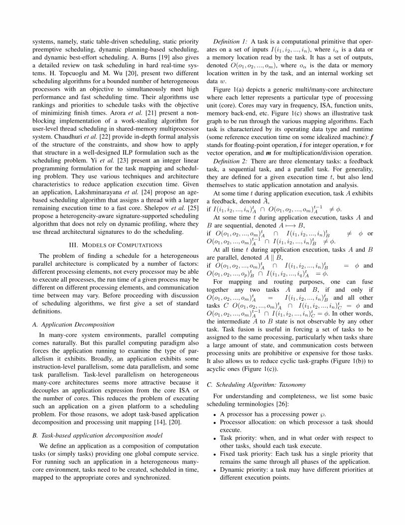
Figure 1(a) depicts a generic multi/many-core architecturewhere each letter represents a particular type of processingunit (core). Cores may vary in frequency, ISA, function units,memory back-end, etc. Figure 1(c) shows an illustrative taskgraph to be run through the various mapping algorithms. Eachtask is characterized by its operating data type and runtime(some reference execution time on some idealized machine): fstands for floating-point operation, i for integer operation, v forvector operation, and m for multiplication/division operation.
Definition 2: There are three elementary tasks: a feedbacktask, a sequential task, and a parallel task. For generality,they are defined for a given execution time t, but also lendthemselves to static application annotation and analysis.
At some time t during application execution, task A exhibitsa feedback, denoted A,if I(i1, i2, ..., in)tA ∩ O(o1, o2, ..., om)t−1
A 6= φ.At some time t during application execution, tasks A and
B are sequential, denoted A 7−→ B,if O(o1, o2, ..., om)tA ∩ I(i1, i2, ..., in)
tB 6= φ or
O(o1, o2, ..., om)t−1A ∩ I(i1, i2, ..., in)
tB 6= φ.
At all time t during application execution, tasks A and Bare parallel, denoted A ‖ B,if O(o1, o2, ..., om)tA ∩ I(i1, i2, ..., in)
tB = φ and
O(o1, o2, ..., op)tB ∩ I(i1, i2, ..., iq)
tA = φ.
For mapping and routing purposes, one can fusetogether any two tasks A and B, if and only ifO(o1, o2, ..., om)tA = I(i1, i2, ..., in)
tB and all other
tasks C O(o1, o2, ..., om)tA ∩ I(i1, i2, ..., in)tC = φ and
O(o1, o2, ..., om)t−1A ∩ I(i1, i2, ..., in)
tC = φ. In other words,
the intermediate A to B state is not observable by any othertask. Task fusion is useful in forcing a set of tasks to beassigned to the same processing, particularly when tasks sharea large amount of state, and communication costs betweenprocessing units are prohibitive or expensive for those tasks.It also allows us to reduce cyclic task-graphs (Figure 1(b)) toacyclic ones (Figure 1(c)).
C. Scheduling Algorithm: Taxonomy
For understanding and completeness, we list some basicscheduling terminologies [26]:
• A processor has a processing power ℘.• Processor allocation: on which processor a task should
execute.• Task priority: when, and in what order with respect to
other tasks, should each task execute.• Fixed task priority: Each task has a single priority that
remains the same through all phases of the application.• Dynamic priority: a task may have different priorities at
different execution points.
mvi mi vi C B D A
i
G F H E mvf mf vf f
mi mi vif K J L I
f
O N P M mvi mi i i
(a) A generic 2D-mesh heteroge-neous multi-cores.
Task 1 [i, 4]
Task 2 [f, 1]
Task 3 [f, 5]
Task 4 [fvm,13]
Task 5 [i, 3]
Task 6 [f, 14]
Task 7 [f, 7]
Task 13 [i, 1]
Task 8 [i, 12]
Task 11 [fi,8]
Task 9 [i, 1]
Task 10 [fi, 2]
Task 12 [im, 9]
end
start
(b) A generic task-based decompositionof an application.
Task 1 [i, 4]
Task 2 [f, 1]
Task {3 7 9 10} [f, 15]
Task 4 [fvm,13]
Task 5 [i, 3]
Task 6 [f, 14]
Task 12 [im, 9]
Task 13 [i, 1]
Task 8 [i, 12]
Task 11 [fi,8]
end
start
(c) The acyclic representation of the ap-plication task graph.
Fig. 1. Example of a generic heterogeneous multi-cores and an application task-based decomposition.
• Preemptive: tasks can be preempted by a higher prioritytask at any time.
• Non-preemptive: once a task starts executing, it will notbe preempted and will therefore execute until completion.
• Cooperative: tasks may only be preempted at definedscheduling points within their execution.
• No migration: Each task is allocated to a processor andno migration is permitted
• Task-level migration: threads of a task may executeon different processors; however each thread can onlyexecute on a single processor.
In our algorithm, many of these characteristics or classifica-tions are not examined, simply because prior work may havedone it, or this particular instance of the problem does notwarrant such examination, or it is obvious how to extend thealgorithm to support such characteristic.
IV. FORMULATION OF TASK-BASED SCHEDULING
Our framework provides a set of algorithms for mappingan application onto a heterogeneous many-core architecture,starting from simple ones to more complex ones, depending onthe level of available system characterization and applicationanalysis data.
A. Definitions
In our framework we define an application A to be A ={T1, T2, ..., Tk} where task Ti = (wi, di, ri, ci), in addition tothe characteristics described above, has the following prop-erties: wi (working set of task Ti), di (deadline of taskTi), ri (input rate of task Ti), and ci (instruction countin task Ti). While we only enumerate these properties, itis not difficult to see that other properties can be incorpo-rated into the framework. We define a processing elementpi = (℘i, lmini
, lmaxi), where ℘i = f(IPC,EUs,CSs),
Lmin represents the memory latency on a cache hit, andLmax the maximum miss latency. ℘i is a function of the IPC(instructions-per-cycle), EUs (execution units), and CSs (cachesizes). The EU factor helps specify which processing unit
has what execution functional unit, e.g., floating-point unit,multiplication unit.
Definition 3: An task admissible schedule (TAS) for anapplication A is a set of tuples that associates to each task Ta set of processing elements such that the data dependenciesand timing constraints between tasks are respected.
Definition 4: A task Ti is schedulable on a processingelement pj , denoted Ti.pj , if its worst-case execution time pjis less than or equal to its deadline. In this work, equations 7and 8 are used to determine task schedulability.
Definition 5: An application is schedulable according to aTAS algorithm if all of its tasks are schedulable.
Definition 6: An application is said to be feasible withrespect to a given heterogeneous many-core system if thereexists at least one TAS solution that can schedule all possiblesequences of tasks that may be generated by the applicationon that system without missing any deadlines or violating anyinter-task dependency.
Definition 7: Given two tasks Ti and Tj , a third task Tkcan be composed out of Ti and Tj for mapping purposes if Tiand Tj are sequential, with no intermediate observable state,and cannot be pipelined.
B. ILP formulation of tasks-based scheduling
An application task graph G = (A,E) is a directed acyclicgraph (DAG) in which each vertex Ti ∈ A represents atask and each edge e(Ti, Tj) ∈ E represents a dependencybetween tasks Ti and Tj . Given a DAG G = (A,E), we wantto find a schedule that minimizes the finishing time of thelast critical task. For the formulation, let us assume that alltasks in A are critical and Tk is the last task. We want toassign to each task Ti ∈ A a pair (ts, tf ) where ts and tfrepresent the starting and finishing time of task Ti under agiven schedule θ. For all edge e(Ti, Tj) ∈ E,wi,j presentsthe amount of data transferred from Ti to Tj during execution(O(o1, o2, ..., om)Ti
∩ I(i1, i2, ..., in)Tj= wi,j). For k
tasks and n processors, the exhaustive listing of scheduleswill produce k!
(k−n)! schedules. This is prohibitive for large
problems. The user can limit the ILP runtime and find asolution over a subset.
C. ILP formulation
The objective function is:
minimize Tk(tf ) (1)
Subject to:
Ti(tf ) ≤ dj (2)
Ti(ts) ≤ Ti(tf ) (3)
if e(Ti, Tj) ∈ E Ti(tf ) < Tj(ts) (4)
∀ e(Ti, Tj) ∈ E, Tj(ts)− Ti(tf ) = di,j (5)
∀ (P (Ti) = pu , P (Tj) = pv), wi,j × bpu,pv ≤ di,j (6)
∀ Ti ∈ A,∀pu ∈ P,E(Ti,pu) = (℘u × ci)
+ = (wi × hitratei,u × lminu)
+ = (wi × (1− hitratei,u)× lmaxu)
(7)
For Ti ∈ A, pu ∈ P, Ti(tf )− Ti(ts) ≥ E(Ti,pu) (8)
∀ Ti ∈ A, pu ∈ P, M(Ti, pu)− (E(Ti,pu) × bi,u) = 0 (9)
∀ Ti ∈ A,n∑
u=1
bi,u = 1 (10)
∀ pu ∈ P,k∑
i=1
M(Ti, pu) ≤ Tk(tf ) (11)
D. Heuristic task-based scheduling algorithms
For applications with a large number of tasks and tightconstraints where the convergence of the ILP formulation ontoa satisfiable solution may take too long, we examine a setof heuristics to provide a fairly effective alternative to theILP formulation. Heuristic H1 is very simple and convergesquickly. It assigns to each task a set of processing units basedon execution affinity, and tries to minimize processor-sharingamong those sets. Its output is a set of processors that canbe used for a task. In general it is good to select the fastestprocessing unit out of the set as the final mapping processor.Our second heuristic H2 takes into account task deadlines inaddition to processor affinity in mapping task to processors. Ittries to minimizes the finishing time per processor as opposedto the global finishing time as done in the ILP formulation.
Ti(ts) ≤ Ti(tf ) (3)
if e(Ti, Tj) ∈ E Ti(tf ) < Tj(ts) (4)
∀ e(Ti, Tj) ∈ E, Tj(ts)− Ti(tf ) = di,j (5)
∀ (P (Ti) = pu , P (Tj) = pv), wi,j × bpu,pv ≤ di,j (6)
∀ Ti ∈ A,∀pu ∈ P,E(Ti,pu) = (℘u × ci)
+ = (wi × hitratei,u × lminu)
+ = (wi × (1− hitratei,u)× lmaxu)
(7)
For Ti ∈ A, pu ∈ P, Ti(tf )− Ti(ts) ≥ E(Ti,pu) (8)
∀ Ti ∈ A, pu ∈ P, M(Ti, pu)− (E(Ti,pu) × bi,u) = 0 (9)
∀ Ti ∈ A,n∑
u=1
bi,u = 1 (10)
∀ pu ∈ P,k∑
i=1
M(Ti, pu) ≤ Tk(tf ) (11)
D. Heuristic task-based scheduling algorithms
For applications with large number of tasks and tightconstraints where the convergence of the ILP formulation ontoa satisfiable solution may take too long, we examine a set ofheuristics to provide a fairly effective alternative to the ILPformulation. Heuristic 1(H1) is very simple and convergesquickly. It assigns to each task a set of processing unitsbased on execution affinity, and tries to minimize processor-sharing among those sets. Its output is a set of processorsthat can be used for a task. In general it is good to selectthe fastest processing unit out of the set as the final mappingprocessor. Our second heuristic 2 (H2) takes into accounttask deadlines in addition to processor affinity in mappingtask to processors. It tries to minimizes the finishing time perprocessor as opposed to the global finishing time as done inthe ILP formulation.
V. EVALUATION METHODOLOGY
To demonstrate the effectiveness of our scheduling algo-rithms, we the Heracles multicore system framework [27], [28]to construct eight different processor core configurations withdifferent execution power, enumerated below: 16-bit micro-processor (Processor1), single-cycle MIPS core (Processor2),7-stage single-threaded MIPS core (Processor3), 7-stage 2-way threaded MIPS core (Processor4), Single lane vectormachine (Processor5), 2-lane vector machine (Processor6),4-lane vector machine (Processor7), 8-lane vector machine(Processor8). Power electronics is one of the key physicallayers of the smart grid that enables highly efficient and fullycontrollable flow of electric power, and promises to deliverup to 30% electric energy savings across all aspects of the
Algorithm 1 Minimizes intersections across all mapping sets(H1).
Assumption: An application A composed of a number oftasks, A = {T1, T2, ..., Tk} and a system with a list ofprocessing elements P = {p1, p2, ..., pn}.Objective: Find a set of task-processor mapping S ={S(T1), S(T2), ..., S(Tk)} such that: ∀ Ti ∈ A, S(Ti) ={pu, ..., pv} with 1 ≤ u < v ≤ n while minimiz-ing ∀(i, j) S(Ti) ∩ S(Tj).Begin∀ Ti ∈ A, S(Ti) = φfor i = 1; i ≤ k; i++ : do
for j = 1; j ≤ n; j ++ : doif (Ti . pj) then
S(Ti) = S(Ti) ∪ {pj}end if
end forend forwhile (∀ Ti ∈ A, |S(Ti)| > 1 and ∀ (i, j) S(Ti)∩S(Tj) 6=φ) do
if (∃ (Ti, Tj) | S(Ti) ∩ S(Tj) 6= φ) thenif ((|S(Ti)| > 1) ∧ (|S(Tj)| > 1)) then
conversion of primary energy into electricity. A typical powerelectronics system consists of an energy source interface, apower converter, and a control unit Figure 2. We take tworepresentative power electronics system applications: namely,a utility grid connected wind turbine converter system and ahybrid electric vehicle motor drive system.
A. Utility Grid Connected Wind Turbine
The general control strategy in wind turbine consists oflimiting the power delivery to the grid under high wind bydoing a stall control, or an active stall, or even a pitch control.To converge to the proper strategy, the control algorithm mayneed a reference emulator of the physical system to checksystem responses, interfaces, and failure modes. Figure 2shows a typical functional block of such system, and Figure 4shows the profiled task graph of our wind turbine application.Figure 3 reports the execution time of all tasks on eachprocessor type.
B. Hybrid Electric Vehicle
Hybrid electric vehicles (HEVs) use two power sources;internal combustion and electric. They are fuel efficient be-cause of their electric motor drive. The motor drive, with a
V. EVALUATION METHODOLOGY
To demonstrate the effectiveness of our scheduling algo-rithms, we use the Heracles multicore system framework [27],[28] to construct eight different processor core configurationswith different execution power, enumerated below: 16-bitmicroprocessor (Processor1), single-cycle MIPS core (Proces-sor2), 7-stage single-threaded MIPS core (Processor3), 7-stage2-way threaded MIPS core (Processor4), Single lane vectormachine (Processor5), 2-lane vector machine (Processor6),4-lane vector machine (Processor7), 8-lane vector machine(Processor8). Power electronics is one of the key physicallayers of the smart grid that enables highly efficient and fullycontrollable flow of electric power, and promises to deliverup to 30% electric energy savings across all aspects of theconversion of primary energy into electricity. A typical powerelectronics system consists of an energy source interface, apower converter, and a control unit. We take two representativepower electronics system applications: namely, a utility gridconnected wind turbine converter system and a hybrid electricvehicle motor drive system.
A. Utility Grid Connected Wind Turbine
The general control strategy in a wind turbine consists oflimiting the power delivery to the grid under high wind bydoing a stall control, or an active stall, or even a pitch control.
Start of System-Step
Diversion Load
Utility Meter
Wind Turbine Sensors
Battery Bank
Rectifier
Inverter
Power Grid Sensors
Previous State
Variables
Previous Distributed
Control State
Input Collector
State Selection
Continuous State 1
Continuous State 2
Continuous State 3
Continuous State 4
State Variables
Emulator Data Storage
Control SystemInput
Analysis Control Algorithm
Monitoring Unit
Monitoring Unit
Data Storage
Distributed Control
Output Signals
Actuators
System Components
End of System-Step
Fig. 4. Task-graph of the wind turbine system application.
Algorithm 2 Minimizes the finishing time on each processor(H2).
Assumption: An application A composed of a number oftasks, A = {T1, T2, ..., Tk} and a system with a list ofprocessing elements P = {p1, p2, ..., pn}.Objective: Find a set of task-processor mapping{S(p1), S(p2), ..., S(pk)} such that ∀ pi ∈ P, S(pi) =
{Ta, ..., Tb} where D(pi) = minimum(k∑u=1
d′u).
d′u =
{du where Tu . pi0 otherwise
Begin∀ pi ∈ P, S(pi) = φ and D(pi) = 0for i = 1; i ≤ n; i++ : do
for j = 1; j ≤ k; j ++ : doif (Tj . pi) then
S(pi) = S(pi) ∪ {Tj}D(pi)+ = dj
end ifend for
end forfor i = 1; i ≤ n; i++ : do
for j = 1; j ≤ n; j ++ : do∀ Tu ∈ S(pi):if ((Tu ∈ S(pj)) ∧ (D(pj) < D(pi))) then
S(pi) = S(pi)− {Tu}D(pi)− = du
end ifend for
end forEnd
controlled inverter system, is needed to deliver powerful andefficient drive to the electric motor. In general, HEV motordrive systems can operates in two modes; namely, conventionalmode and regenerative breaking mode. In conventional mode,the internal combustion engine supplies the voltage that passesthrough the inverter block to drive the induction motor;whereas in the regenerative breaking mode, the inductionmachine acts as a generator and the inverter block acts asa three-phase rectifier.
Fig. 3. Total execution time for all tasks in the wind turbine application perprocessor.
C. Results
In this section, we present the output of our three schedulingalgorithms. In general, H1performs poorly compare to the theILP-based mapping, because it does not takes into accountmany of the system architectural features. If compute-intensivetask is inadvertently mapped into a weaker core it can impactthe whole application execution time. H2 performs betterH1, and it is within 20% to 70% of the ILP-based mappingefficiency.
VI. CONCLUSION
We present in this work an ILP formulation and two non-iterative heuristics that can handle different application perfor-mance targets and architectural features for scheduling a task-based application onto a heterogenous many-core architecture.We use RTL-based heterogenous many-core systems and realpower electronics applications for evaluations of mapping al-gorithms. In the future we will expand on these algorithms andcompare them with implementable closely related schemes.
To converge to the proper strategy, the control algorithm mayneed a reference emulator of the physical system to checksystem responses, interfaces, and failure modes. Figure 3shows the profiled task graph of our wind turbine application.Figure 2 reports the execution time of all tasks on eachprocessor type.
0
5000
10000
15000
20000
25000
start
UM I R
DL
BB
PG
WT
PSV
PDC
IA
IC
CA
MU
SS
MUDS
CS1
CS2
CS3
CS4
SV
EDS
CS
DC
OS
A
SC
end
Execu&
on Tim
e (ns)
Tasks
Processor1
Processor2
Processor3
Processor4
Processor5
Processor6
Processor7
Processor8
Fig. 2. Total execution time for all tasks in the wind turbine application perprocessor.
B. Hybrid Electric Vehicle
Hybrid electric vehicles (HEVs) use two power sources;internal combustion and electric. They are fuel efficient be-cause of their electric motor drive. The motor drive, with a
controlled inverter system, is needed to deliver powerful andefficient drive to the electric motor. In general, HEV motordrive systems can operate in two modes; namely, conventionalmode and regenerative breaking mode. In conventional mode,the internal combustion engine supplies the voltage that passesthrough the inverter block to drive the induction motor;whereas in the regenerative breaking mode, the inductionmachine acts as a generator and the inverter block acts asa three-phase rectifier.C. Results
In this section, we present the output of our three schedulingalgorithms. In general, H1performs poorly when compared tothe ILP-based mapping, because it does not take into accountmany of the system architectural features. If a compute-intensive task is inadvertently mapped into a weaker core itcan impact the whole application execution time. H2 performsbetter then H1, and it is within 20% to 70% of the ILP-basedmapping efficiency.
VI. CONCLUSION
We present in this work an ILP formulation and twonon-iterative heuristics that can handle different applicationperformance targets and architectural features for scheduling atask-based application onto a heterogeneous many-core archi-tecture. We use RTL-based heterogeneous many-core systemsand real power electronics applications for evaluations ofmapping algorithms. In the future we will expand on thesealgorithms and compare them with closely related schemes.
REFERENCES
[1] http://www.tilera.com/, “Tilera tile-gx processor,” 2012.[2] D. Pham, S. Asano, M. Bolliger, M. Day, H. Hofstee, C. Johns, J. Kahle,
A. Kameyama, J. Keaty, Y. Masubuchi, M. Riley, D. Shippy, D. Stasiak,M. Suzuoki, M. Wang, J. Warnock, S. Weitzel, D. Wendel, T. Yamazaki,and K. Yazawa, “The design and implementation of a first-generationcell processor,” in Solid-State Circuits Conference, 2005. Digest ofTechnical Papers. ISSCC. 2005 IEEE International, pp. 184 –592 Vol.1, Feb. 2005.
[3] K. Asanovic, R. Bodik, J. Demmel, T. Keaveny, K. Keutzer, J. Kubi-atowicz, N. Morgan, D. Patterson, K. Sen, J. Wawrzynek, D. Wessel,and K. Yelick, “A view of the parallel computing landscape,” Commun.ACM, vol. 52, pp. 56–67, Oct. 2009.
[4] R. Kumar, D. M. Tullsen, P. Ranganathan, N. P. Jouppi, and K. I. Farkas,“Single-isa heterogeneous multi-core architectures for multithreadedworkload performance,” in Proceedings of the 31st annual internationalsymposium on Computer architecture, ISCA ’04, (Washington, DC,USA), pp. 64–, IEEE Computer Society, 2004.
[5] H. Kopetz, Real-Time Systems : Design Principles for DistributedEmbedded Applications (The International Series in Engineering andComputer Science). Springer, Apr. 1997.
[6] K. Van Craeynest, A. Jaleel, L. Eeckhout, P. Narvaez, and J. Emer,“Scheduling heterogeneous multi-cores through performance impactestimation (pie),” in Computer Architecture (ISCA), 2012 39th AnnualInternational Symposium on, pp. 213 –224, June 2012.
[7] J. Chen and L. John, “Efficient program scheduling for heterogeneousmulti-core processors,” in Design Automation Conference, 2009. DAC’09. 46th ACM/IEEE, pp. 927 –930, July 2009.
[8] T. Li, D. Baumberger, D. A. Koufaty, and S. Hahn, “Efficient oper-ating system scheduling for performance-asymmetric multi-core archi-tectures,” in Supercomputing, 2007. SC ’07. Proceedings of the 2007ACM/IEEE Conference on, pp. 1 –11, Nov. 2007.
[9] M. Garey and D. Johnson, “Complexity results for multiprocessorscheduling under resource constraints,” SIAM Journal on Computing,vol. 4, no. 4, pp. 397–411, 1975.
[10] D. Karger, C. Stein, and J. Wein, “Scheduling algorithms,” 1997.
Start of System-Step
Diversion Load
Utility Meter
Wind Turbine Sensors
Battery Bank
Rectifier
Inverter
Power Grid Sensors
Previous State
Variables
Previous Distributed
Control State
Input Collector
State Selection
Continuous State 1
Continuous State 2
Continuous State 3
Continuous State 4
State Variables
Emulator Data Storage
Control SystemInput
Analysis Control Algorithm
Monitoring Unit
Monitoring Unit
Data Storage
Distributed Control
Output Signals
Actuators
System Components
End of System-Step
Fig. 3. Task-graph of the wind turbine system application.
0
200
400
600
800
1000
1200
1400
start/p8
DL
/p4
UM/p4
WT/p6
BB
/p3
R/p4
I/p
4 PG
/p7
PSV/p6
PD
C/p8
IA/p8
MU/
p7
CA/p8
IC/p8
SS/p8
CS1/p7
CS2/p7
CS3/p7
CS4/p7
MUD
S/p6
SV
/p7
EDS/p4
CS/p8
OS/p8
DC
/p8
A/p7
SC/p8
end/p7
Execu&
on Tim
e (ns)
Task-‐to-‐processor Mapping
Start
Finish
(a) ILP schedule solution for the wind turbinesystem application.
0
5000
10000
15000
20000
25000
30000
35000
start/p6
DL
/p8
UM/p5
WT/p8
BB
/p8
R/p3
I/p
4 PG
/p8
PSV/p6
PD
C/p1
IA/p6
MU/
p1
CA/p8
IC/p7
SS/p6
CS1/p6
CS2/p6
CS3/p6
CS4/p6
MUD
S/p8
SV
/p8
EDS/p8
CS/p4
OS/p8
DC
/p8
A/p8
SC/p8
end/p7
Execu&
on Tim
e (ns)
Task-‐to-‐processor Mapping
Start
Finish
(b) H1 schedule solution for the wind turbinesystem application.
0
200
400
600
800
1000
1200
1400
1600
start/p2
DL
/p8
UM/p7
WT/p8
BB
/p8
R/p5
I/p
6 PG
/p8
PSV/p8
PD
C/p8
IA/p8
MU/
p5
CA/p8
IC/p7
SS/p7
CS1/p6
CS2/p7
CS3/p6
CS4/p6
MUD
S/p7
SV
/p8
EDS/p8
CS/p7
OS/p7
DC/p8
A/p6
SC/p8
end/p5
Execu&
on Tim
e (ns)
Task-‐to-‐processor Mapping
Start
Finish
(c) H2 schedule solution for the wind turbinesystem application.
Fig. 4. Scheduling of wind turbine system application
0
200
400
600
800
1000
1200
1400
1600
start/p8
GP/p5
CR
/p3
E/p8
C/p5
BP
/p3
SM/p4
PG/p3
SG/p4
PSV/p7
PD
C/p7
IA/p8
CA/p8
MU/p6
GE/p8
SS/p8
CS1/p8
CS2/p7
CS3/p8
SV
/p8
CS/p8
EDS/p5
MUDS/p4
OS/p8
DC/p7
A/p7
SC/p8
end/p8
Execu&
on Tim
e (ns)
Task-‐to-‐processor Mapping
Start
Finish
(a) ILP schedule solution for the hybrid elec-tric vehicle application.
0
1000
2000
3000
4000
5000
6000
7000
8000
9000
10000
start/p2
GP/p8
CR
/p8
E/p7
C/p8
BP
/p8
SM/p5
PG/p5
SG/p8
PSV/p5
PD
C/p6
IA/p4
CA/p8
MU/p6
GE/p7
SS/p6
CS1/p6
CS2/p6
CS3/p6
SV
/p8
CS/p2
EDS/p8
MUDS
/p8
OS/p8
DC
/p7
A/p8
SC/p8
end/p2
Execu&
on Tim
e (ns)
Task-‐to-‐processor Mapping
Start
Finish
(b) H1 schedule solution for the hybrid electricvehicle application.
0
500
1000
1500
2000
2500
3000
start/p2
GP
/p8
CR/p8
E/p7
C/p8
BP
/p8
SM/p5
PG/p5
SG/p8
PSV/p8
PD
C/p8
IA/p8
CA/p8
MU/p5
GE/p7
SS/p8
CS1/p6
CS2/p7
CS3/p6
SV
/p8
CS/p7
EDS/p8
MUDS
/p8
OS/p7
DC
/p4
A/p6
SC/p7
end/p6
Execu&
on Tim
e (ns)
Task-‐to-‐processor Mapping
Start
Finish
(c) H2 schedule solution for the hybrid electricvehicle application.
Fig. 5. Scheduling of hybrid electric vehicle application
[11] D. G. Feitelson, L. Rudolph, U. Schwiegelshohn, K. C. Sevcik, K. C,and P. Wong, “Theory and practice in parallel job scheduling,” 1994.
[12] T. Yang and A. Gerasoulis, “Dsc: Scheduling parallel tasks on anunbounded number of processors,” IEEE Transactions on Parallel andDistributed Systems, vol. 5, pp. 951–967.
[13] M. R. Garey and D. S. Johnson, “Two-processor scheduling with start-times and deadlines,” SIAM Journal on Computing, vol. 6, pp. 416–426,1977.
[14] Y.-K. Kwok and I. Ahmad, “Static scheduling algorithms for allocatingdirected task graphs to multiprocessors,” 1999.
[15] M. Becchi and P. Crowley, “Dynamic thread assignment on heteroge-neous multiprocessor architectures,” in Proceedings of the 3rd confer-ence on Computing frontiers, CF ’06, pp. 29–40, ACM, 2006.
[16] D. Koufaty, D. Reddy, and S. Hahn, “Bias scheduling in heterogeneousmulti-core architectures,” in Proceedings of the 5th European conferenceon Computer systems, EuroSys ’10, pp. 125–138, ACM, 2010.
[17] B. B. Brandenburg, J. M. Calandrino, and J. H. Anderson, “On thescalability of real-time scheduling algorithms on multicore platforms: Acase study,” 2008.
[18] K. Ramamritham and J. Stankovic, “Scheduling algorithms and operat-ing systems support for real-time systems,” Proceedings of the IEEE,vol. 82, pp. 55 –67, Jan. 1994.
[19] A. Burns, “Scheduling hard real-time systems: a review,” SoftwareEngineering Journal, vol. 6, pp. 116 –128, May 1991.
[20] H. Topcuoglu and M. you Wu, “Performance-effective and low-complexity task scheduling for heterogeneous computing,” IEEE Trans-actions on Parallel and Distributed Systems, vol. 13, pp. 260–274, 2002.
[21] N. S. Arora, R. D. Blumofe, and C. G. Plaxton, “Thread schedulingfor multiprogrammed multiprocessors,” in In Proceedings of the Tenth
Annual ACM Symposium on Parallel Algorithms and Architectures(SPAA), Puerto Vallarta, pp. 119–129, 1998.
[22] S. Chaudhuri, R. A. Walker, and J. E. Mitchell, “Analyzing and exploit-ing the structure of the constraints in the ilp approach to the schedulingproblem,” IEEE Transactions on VLSI Systems, vol. 2, pp. 456–471,1994.
[23] Y. Yi, W. Han, X. Zhao, A. Erdogan, and T. Arslan, “An ilp formulationfor task mapping and scheduling on multi-core architectures,” in Design,Automation Test in Europe Conference Exhibition, 2009. DATE ’09.,pp. 33 –38, April 2009.
[24] N. B. Lakshminarayana, J. Lee, and H. Kim, “Age based schedulingfor asymmetric multiprocessors,” in Proceedings of the Conference onHigh Performance Computing Networking, Storage and Analysis, SC’09, pp. 25:1–25:12, ACM, 2009.
[25] D. Shelepov, J. C. Saez Alcaide, S. Jeffery, A. Fedorova, N. Perez,Z. F. Huang, S. Blagodurov, and V. Kumar, “Hass: a scheduler forheterogeneous multicore systems,” SIGOPS Oper. Syst. Rev., vol. 43,pp. 66–75, Apr. 2009.
[26] R. I. Davis and A. Burns, “A survey of hard real-time scheduling formultiprocessor systems,” ACM Comput. Surv., vol. 43, pp. 35:1–35:44,Oct. 2011.
[27] M. Kinsy, M. Pellauer, and S. Devadas, “Heracles: Fully synthesizableparameterized mips-based multicore system,” in Field ProgrammableLogic and Applications (FPL), 2011 International Conference on,pp. 356 –362, Sept. 2011.
[28] M. A. Kinsy, M. Pellauer, and S. Devadas, “Heracles: A tool for fast rtl-based design space exploration of multicore processors,” in Proceedingsof the ACM/SIGDA International Symposium on Field ProgrammableGate Arrays, FPGA ’13, pp. 125–134, ACM, 2013.