Alien Hardware Diagnosis in ICs Using Path Delay Measurements. Spyros Tragoudas (PI ) Dept . of Electrical and Computer Engineering Southern Illinois University, Carbondale, IL 62901. Project Overview and Description. Problem Diagnosis of multiple delay-defective embedded segments - PowerPoint PPT Presentation
17
Center for Embedded Systems | An NSF Industry/University Cooperative Research CONFIDENTIAL Alien Hardware Diagnosis in ICs Using Path Delay Measurements Spyros Tragoudas (PI) Dept. of Electrical and Computer Engineering Southern Illinois University, Carbondale, IL 62901
Transcript
Center for Embedded Systems | An NSF Industry/University Cooperative Research Center CONFIDENTIAL
Alien Hardware Diagnosis in ICs Using Path Delay
MeasurementsSpyros Tragoudas (PI)
Dept. of Electrical and Computer Engineering
Southern Illinois University, Carbondale, IL 62901
Center for Embedded Systems | An NSF Industry/University Cooperative Research Center CONFIDENTIAL
Project Overview and Description
• Problem– Diagnosis of multiple delay-defective embedded
segments– A scalable algorithmic approach to determine the
•An integer value can be assigned to each variable so that all equations are satisfied
Center for Embedded Systems | An NSF Industry/University Cooperative Research Center CONFIDENTIAL
Recommending the most probable solution 1
Heuristic H-sim (analysis of several segments simultaneously)
•Recommend solution sets containing concurrently the top ranking segments
•For segments {X1, X7, X5} we have,First Solution Set
X1 = X3 = X4 = X5 = X7 = 1
Third Solution Set
X1 = X5 = X6 = 1, X7 = 2
•First inspect the segments in the smallest collection
6
Segment
Participating
solution sets
X1 3
X7 3
X5 2
X3 1
X4 1
X6 1
X10 1
X11 1
When the SAT solver returns a large number of solutions
Table 1: Prioritizing segments
Center for Embedded Systems | An NSF Industry/University Cooperative Research Center CONFIDENTIAL
Recommending the most probable solution 2
Heuristic H-inc (incremental physical analysis)
•Applied during root-cause analysis (RCA)•In RCA the goal is to swiftly identify the actual defects from the suspect set•Choose the highest ranking segment
» X1is a hit
•Discard solution sets not containing X1•Continue until only one solution set remains•Only X1, X7, X5 were physically inspected
7
Segment
Participating
solution sets
Hit/Miss
X1 3 H
X7 3 H
X5 2 H
X3 1 M
X4 1 -
X6 1 H
X10 1 -
X11 1 -
Table 1: Prioritizing segments for physical
inspection
When the SAT solver returns a large number of solutions
Center for Embedded Systems | An NSF Industry/University Cooperative Research Center CONFIDENTIAL 8
Center for Embedded Systems | An NSF Industry/University Cooperative Research Center CONFIDENTIAL
Bounded-SAT Modeling
• The formula F in Conjunctive Normal Form (CNF) denotes a Boolean function [Silva’98]
f : {0,1}n {0,1}
• F consists of a product of clauses, where each clause C is a sum of literals l
C = (l1 + l2 +……..+ ln)
• Each clause C corresponds to a measured path and each literal l corresponds to a gate delay variable
• Bounded-SAT requires that a predetermined number of literals from each clause be assigned ‘1’
• One of the satisfying assignments points exactly to the locations of alien components
9
Center for Embedded Systems | An NSF Industry/University Cooperative Research Center CONFIDENTIAL 10
Bounded-SAT Modeling
• Each constraint of the ILP is modeled as a clause with non-negated literals.
• Clauses are bounded based on the excess delay
Consider the following set of reduced equations
G1 + G9 = 1
G3 + G6 + G10 = 1G8 + G12 = 1G3 + G7 + G12 = 2
The CNF is modeled as
F = (G1 V G9) Λ (G3 V G6 V G10) Λ (G8 V G12) Λ (G3 V G7 V G12) 1 1 1 2 Bounds on Clauses
Center for Embedded Systems | An NSF Industry/University Cooperative Research Center CONFIDENTIAL
Variable replication in SAT modeling
• A Boolean assignment can only assign a ‘0’ or ‘1’ to a particular variable
• A Boolean ‘1’ assignment indicates a defect of size Δ• Variable replication is used to consider defects of
G1 + G9 = 1G3 + G6 + G10 = 1G8 + G12 = 1G3 + G71 + G72 + G121 + G122 = 2• Observe that G7 and G12 have two instances
• G3 is in an equation which restricts its defect size to 1× Δ
Center for Embedded Systems | An NSF Industry/University Cooperative Research Center CONFIDENTIAL
Scalable Algorithmic Approach
NSF IUCRC Embedded Systems 12
n r Generalapproach
Guard band approach
% dec
5 2 22 15 32
6 3 44 30 32
9 2 476 93 80
12 4 3601 1012 72
16 3 64976 2380 96
Table 1: Overhead of both approaches
Clauses per path
Center for Embedded Systems | An NSF Industry/University Cooperative Research Center CONFIDENTIAL
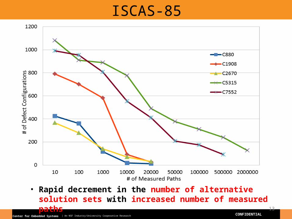
ISCAS-85
13
• Rapid decrement in the number of alternative solution sets with increased number of measured paths
Center for Embedded Systems | An NSF Industry/University Cooperative Research Center CONFIDENTIAL
ISCAS-89 Benchmarks
14
• Rapid decrement in the number of alternative solution sets with increased number of measured paths
Center for Embedded Systems | An NSF Industry/University Cooperative Research Center CONFIDENTIAL
ITC-99 Benchmarks
15
• Rapid decrement in the number of alternative solution sets with increased number of measured paths
Center for Embedded Systems | An NSF Industry/University Cooperative Research Center CONFIDENTIAL
Benchmarks
Injected
Defects
Solution sets for Max. measured
paths
Proposed Heuristics
H-Sim (top 40%) H-Inc
HR % DR % HR % DR %
C5315 164 127 70.7 95.73 88.7 97.73
C7552 138 91 67.9 88.17 83.26 95.6
S35932 179 156 82.3 95.53 90 95.53
S38417 211 93 69.56 85.6 77.6 88.17
B15 345 998 66.25 70.2 71.32 78.4
B17 401 677 64.11 63.7 77.5 73.5
16
Center for Embedded Systems | An NSF Industry/University Cooperative Research Center CONFIDENTIAL
References
[1] Ying-Yen Chen, Jing-Jia Liou, Diagnosis Framework for Locating Failed Segments of Path Delay Faults, in IEEE Transactions on VLSI Sytems, Vol. 16, No.6, June 2008.[2] Ying-Yen Chen, Min-Pin Kuo, Jing-Jia Liou, Diagnosis Framework for Locating Failed Segments of Path Delay Faults, in Proceedings of International Test Conference, 2005.[3] Tayade R., Nassif S., and Abraham J. Analytical model for the impact of multiple input switching noise on timing. In Proceedings of the 2008 Asia and South Pacific Design Automation Conference (Seoul, Korea, January 21 - 24, 2008).[4] Edward Flanigan, Spyros Tragoudas, Enhanced Identification of Strong Robustly Testable Paths, in Proceedings of International Symposium on Quality Electronic Design, 2007.[5] Ahish M Somashekar, Spyros Tragoudas, SAT based diagnosis of multiple delay defects in Integrated Circuits, submitted to International Test Conference 2012