Isopropylbenzene, also known as cumene, is among the top commodity chemicals, taking about 7 – 8% from the total worldwide propylene consumption. Today, the cumene is used almost exclusively for manufacturing phenol and acetone.
This case study deals with the design and simulation of a medium size plant of 100 kton cumene per year. The goal is performing the design by two essentially different methods. The fi rst one is a classical approach, which handles the process synthesis and energy saving with distinct reaction and separation sections. In the second alternative a more innovative technology is applied based on reactive distillation.
Table 6.1 presents the purity specifi cations. The target of design is achieving over 99.9% purity. It may be seen that higher alkylbenzenes impurities are unde-sired. Ethyl - and butylbenzene can be prevented by avoiding olefi ns and butylenes in the propylene feed. N - propylbenzene appears by equilibrium between isomers and can be controlled by catalyst selectivity.
In this project we consider as raw materials benzene of high purity and propyl-ene with only 10% propane. As an exercise, the reader can examine the impact of higher propane ratios on design.
6.1.2 Manufacturing Routes
General information about chemistry, technology and economics can be found in the standard encyclopaedic material [1, 2] , as well as in more specialized books [3] . The manufacturing process is based on the addition of propylene to benzene:
C H Bz C H P C H C H IPB3 3 76 6 6 6 5( ) ( ) ( )+ = − (6.1)
174 6 Alkylation of Benzene by Propylene to Cumene
Beside isopropyl benzene (IPB) a substantial amount of polyalkylates is formed by consecutive reactions, mostly as C6H5 - (C3H7) 2 (DIPB) with some C6H5 - (C3H7) 3 (TPB). The main reaction has a large exothermal effect, of − 113 kJ/mol in standard conditions. The alkylation reaction is promoted by acid - type catalysts. The synthesis can be performed in gas or liquid phase. Before 1990 gas - phase alkylation processes dominated, but today liquid - phase processes with zeolite cata-lysts prevail. Recent developments make use of reactive distillation.
Cumene processes based on zeolites are environmentally friendly, offering high productivity and selectivity. The most important are listed in Table 6.2 [4] . The catalyst performance determines the type and operational parameters of the reactor and, accordingly the fl owsheet confi guration. The technology should fi nd an effi -cient solution for using the reaction heat inside the process and and/or making it available to export. By converting the polyalkylbenzenes into cumene an overall yield of nearly 100% may be achieved.
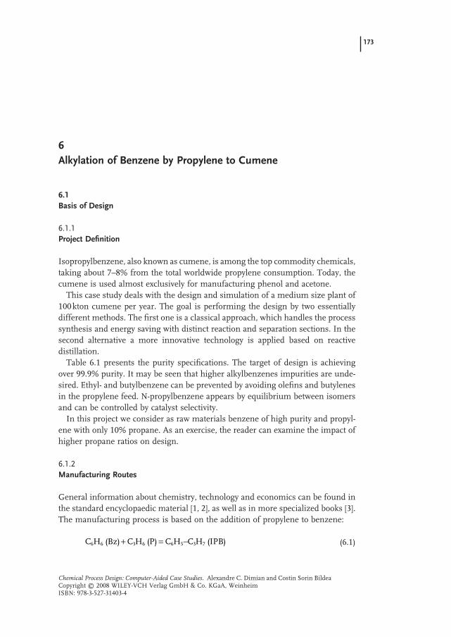
Figure 6.1 illustrates a typical conceptual fl owsheet [3] . Propylene is dissolved in a large excess of benzene (more than 5 : 1 molar ratio) at suffi ciently high pres-sure that ensures only one liquid phase at the reaction temperature, usually between 160 and 240 ° C. The alkylation reactor is a column fi lled with fi xed - bed catalyst, designed to ensure complete conversion of propylene. The reactor effl uent is sent to the separation section, in this case a series of four distillation columns: propane (LPG) recovery, recycled benzene, cumene product and separation of polyisopropylbenzenes. The fl owsheet involves two recycles: nonreacted benzene to alkylation and polyalkylbenzenes to transalkylation. The minimization of recycle fl ows and of energy consumption in distillation are the key objectives of the design. These can be achieved by employing a highly active and selective catalyst, as well as by implementing advanced heat integration.
Table 6.1 Specifi cations for cumene [1, 3] .
Cumene purity 99.94 wt% min.
Bromine index < 5 Ethylbenzene < 100 ppm n - propylbenzene < 200 ppm Butylbenzene < 100 ppm
Table 6.2 Technologies for cumene manufacturing based on zeoltes.
Process Mobil - Raytheon CD - Tech Q - max/UOP Enichem
Zeolite 3 - DDM MCM - 22 Y Beta Beta Reactor Fixed bed Fixed bed Catalytic distillation Fixed bed Fixed bed
Table 6.3 illustrates a typical material balance of a cumene plant using Dow - Kellog technology [3] . The propylene may contain up to 40% propane, but without ethylene and butylene. Beside cumene, variable amounts of LPG can be obtained as subproducts. Energy is also exported as LP steam, although it is consumed as well as other utilities (fuel, cooling water, electricity).
6.1.3 Physical Properties
Table 6.4 presents some fundamental physical constants. Critical pressures of propane and propylene are above 40 bar, but in practice 20 to 30 bar are suffi cient
176 6 Alkylation of Benzene by Propylene to Cumene
to ensure a high concentration of propylene in the coreactant benzene. From the separation viewpoint one may note large differences in the boiling points of com-ponents and no azeotrope formation. In consequence, the design of the separation train should not raise particular problems. Since the liquid mixtures behave almost ideally a deeper thermodynamic analysis is not necessary. The use of vacuum distillation is expected because of the high boiling points of the polyalkylated benzenes.
6.2 Reaction - Engineering Analysis
6.2.1 Chemical - Reaction Network
The mechanism of benzene alkylation with propylene involves the protonation of the catalyst acidic sites [5, 6] leading to isopropylbenzene, and further di - isopropylbenzenes and tri - isopropylbenzenes. By the isomerization some n - propylbenzene appears, which is highly undesirable as an impurity. The presence of stronger acid sites favors the formation of propylene oligomers and other hydro-carbon species. Therefore, high selectivity of the catalyst is as important as high activity. It is remarkable that the polyalkylates byproducts can be reconverted to cumene by reaction with benzene. Below, the chemical reactions of signifi cance are listed:
Alkylation
(i)
Table 6.4 Basic physical properties of components in the outlet reactor mixture.
Components Formula M w T f ( ° C) T b ( ° C) P c (bar) T c ( ° C)
Propylene C 3 H 6 42 − 186.3 − 47.6 46.0 91.75 Propane C 3 H 8 44 − 181.7 − 42.17 42.5 96.67 Benzene C 6 H 6 78 6.6 80.1 48.8 289.0 1 - hexene C 6 H 12 84 − 139.7 63.5 31.4 231.0 Cumene C 6 H 5 - C 3 H 7 120 − 96.9 152.5 32.1 357.85 Di - isopropylbenzene C 6 H 4 - (C 3 H 7 ) 2 162 – 210.5 (para) – – Tri - isopropylbenzene C 6 H 4 - (C 3 H 7 ) 3 204 – (232) – –
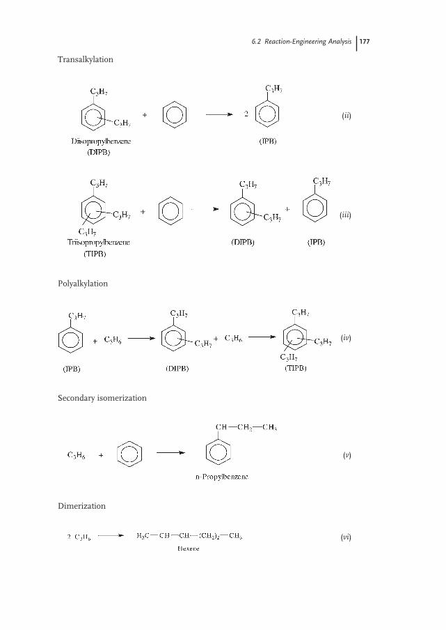
Transalkylation
(ii)
(iii)
Polyalkylation
(iv)
Secondary isomerization
(v)
Dimerization
(vi)
6.2 Reaction-Engineering Analysis 177
178 6 Alkylation of Benzene by Propylene to Cumene
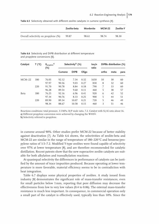
Other side reactions
(vii)
6.2.2 Catalysts for the Alkylation of Aromatics
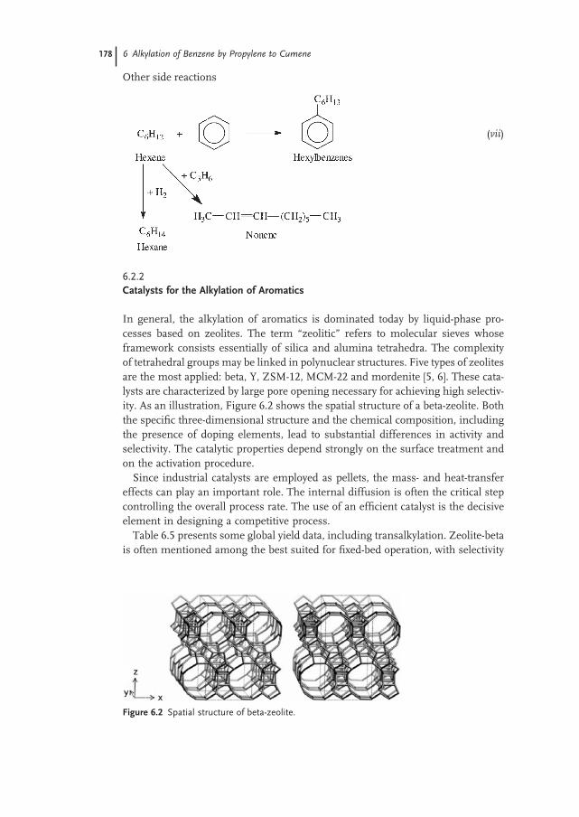
In general, the alkylation of aromatics is dominated today by liquid - phase pro-cesses based on zeolites. The term “ zeolitic ” refers to molecular sieves whose framework consists essentially of silica and alumina tetrahedra. The complexity of tetrahedral groups may be linked in polynuclear structures. Five types of zeolites are the most applied: beta, Y, ZSM - 12, MCM - 22 and mordenite [5, 6] . These cata-lysts are characterized by large pore opening necessary for achieving high selectiv-ity. As an illustration, Figure 6.2 shows the spatial structure of a beta - zeolite. Both the specifi c three - dimensional structure and the chemical composition, including the presence of doping elements, lead to substantial differences in activity and selectivity. The catalytic properties depend strongly on the surface treatment and on the activation procedure.
Since industrial catalysts are employed as pellets, the mass - and heat - transfer effects can play an important role. The internal diffusion is often the critical step controlling the overall process rate. The use of an effi cient catalyst is the decisive element in designing a competitive process.
Table 6.5 presents some global yield data, including transalkylation. Zeolite - beta is often mentioned among the best suited for fi xed - bed operation, with selectivity
Figure 6.2 Spatial structure of beta - zeolite.
6.2 Reaction-Engineering Analysis 179
in cumene around 90%. Other studies prefer MCM - 22 because of better stability against deactivation [7] . As Table 6.6 shows, the selectivities of zeolite - beta and MCM - 22 are similar in the range of temperature of 180 – 220 ° C and benzene/pro-pylene ratios of 3.5 – 7.2. Modifi ed Y - type zeolites were found capable of selectivity over 97% at lower temperature [8] , and are therefore recommended for catalytic distillation. Recent patents show that the new superactive zeolite catalysts are suit-able for both alkylation and transalkylation reactions.
At quasiequal selectivity the differences in performance of catalysts can be justi-fi ed by the amount of trace impurities produced. Because operating at lower tem-perature is more favorable, material effi ciency seems to be in contradiction with heat integration.
Table 6.7 displays some physical properties of zeolites. A study issued from industry [8] demonstrates the signifi cant role of mass - transfer resistances, even for small particles below 1 mm, reporting that pore diffusion may decrease the effectiveness from low to very low values (0.4 to 0.06). The external mass - transfer resistance is much less important. In consequence, in commercial operation only a small part of the catalyst is effectively used, typically less than 10%. Since the
Table 6.5 Selectivity obtained with different zeolite catalysts in cumene synthesis [4] .
Zeolite - beta Mordenite MCM - 22 Zeolite - Y
Overall selectivity on propylene (%) 99.87 98.61 98.74 98.30
Table 6.6 Selectivity and DIPB distribution at different temperature and propylene conversions [6] .
Reactions conditions: total pressure, 3.5 MPa; B/P mole ratio, 7.2. Catalyst with Si/Al ratio about 16. a) Different propylene conversion were achieved by changing the WHSV. b) Selectivity referred to propylene.
180 6 Alkylation of Benzene by Propylene to Cumene
reduction of particle size is restricted in practice for technological reasons, another alternative is the use of a surface - coated monolith catalyst. However, high exother-micity raises problems with respect to temperature control. In conclusion, the subtle combination of chemical and physical factors leads to a large variability in the behavior of the commercial catalysts with respect to reaction rate and selectivity.
6.2.3 Thermal Effects
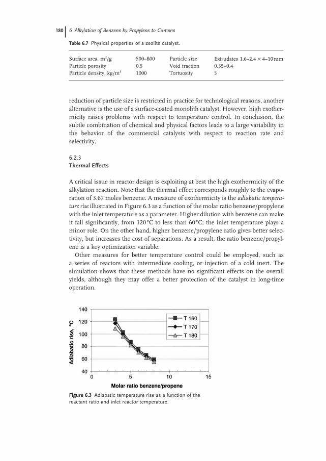
A critical issue in reactor design is exploiting at best the high exothermicity of the alkylation reaction. Note that the thermal effect corresponds roughly to the evapo-ration of 3.67 moles benzene. A measure of exothermicity is the adiabatic tempera-
ture rise illustrated in Figure 6.3 as a function of the molar ratio benzene/propylene with the inlet temperature as a parameter. Higher dilution with benzene can make it fall signifi cantly, from 120 ° C to less than 60 ° C; the inlet temperature plays a minor role. On the other hand, higher benzene/propylene ratio gives better selec-tivity, but increases the cost of separations. As a result, the ratio benzene/propyl-ene is a key optimization variable.
Other measures for better temperature control could be employed, such as a series of reactors with intermediate cooling, or injection of a cold inert. The simulation shows that these methods have no signifi cant effects on the overall yields, although they may offer a better protection of the catalyst in long - time operation.
Table 6.7 Physical properties of a zeolite catalyst.
Figure 6.3 Adiabatic temperature rise as a function of the reactant ratio and inlet reactor temperature.
6.2 Reaction-Engineering Analysis 181
6.2.4 Chemical Equilibrium
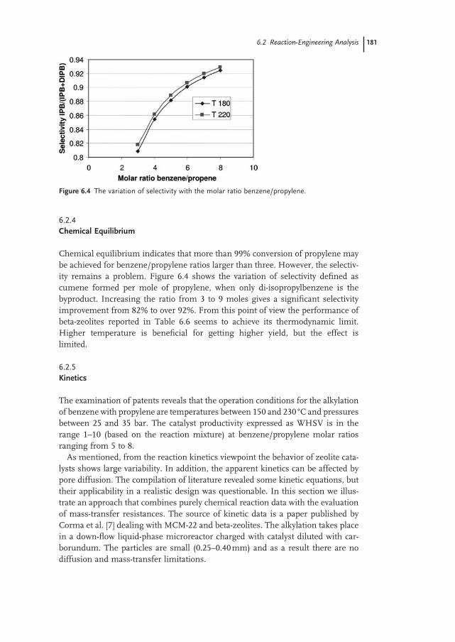
Chemical equilibrium indicates that more than 99% conversion of propylene may be achieved for benzene/propylene ratios larger than three. However, the selectiv-ity remains a problem. Figure 6.4 shows the variation of selectivity defi ned as cumene formed per mole of propylene, when only di - isopropylbenzene is the byproduct. Increasing the ratio from 3 to 9 moles gives a signifi cant selectivity improvement from 82% to over 92%. From this point of view the performance of beta - zeolites reported in Table 6.6 seems to achieve its thermodynamic limit. Higher temperature is benefi cial for getting higher yield, but the effect is limited.
6.2.5 Kinetics
The examination of patents reveals that the operation conditions for the alkylation of benzene with propylene are temperatures between 150 and 230 ° C and pressures between 25 and 35 bar. The catalyst productivity expressed as WHSV is in the range 1 – 10 (based on the reaction mixture) at benzene/propylene molar ratios ranging from 5 to 8.
As mentioned, from the reaction kinetics viewpoint the behavior of zeolite cata-lysts shows large variability. In addition, the apparent kinetics can be affected by pore diffusion. The compilation of literature revealed some kinetic equations, but their applicability in a realistic design was questionable. In this section we illus-trate an approach that combines purely chemical reaction data with the evaluation of mass - transfer resistances. The source of kinetic data is a paper published by Corma et al. [7] dealing with MCM - 22 and beta - zeolites. The alkylation takes place in a down - fl ow liquid - phase microreactor charged with catalyst diluted with car-borundum. The particles are small (0.25 – 0.40 mm) and as a result there are no diffusion and mass - transfer limitations.
Figure 6.4 The variation of selectivity with the molar ratio benzene/propylene.
182 6 Alkylation of Benzene by Propylene to Cumene
The surface chemical reaction seems to follow the Eley – Rideal (ER) mechanism, in which the adsorption of propylene is predominant over benzene, as represented by the equation:
r
k K c
K cA
P P
P P
=+0
1
(6.2)
in whick k 0 is the surface reaction constant, K P the adsorption constant of propyl-ene, and c P its the bulk propylene concentration. The mentioned reference supplies experimental values for k 1 = k 0 K P but not for K P . Because on the interval of interest K P c P << 1 we may assume a pseudo - fi rst - order reaction.
The overall process can be affected by pore diffusion and external mass transfer. Molecular diffusion coeffi cients D PB may be calculated by Aspen Plus. Effective pore diffusion may be estimated by the relation D P,eff = D PB ( ε p / τ p ) = 0.1 D PB , in which ε p is the particle porosity and τ p the tortuosity. Furthermore, the Thiele modulus and internal effectiveness can be calculated as:
φ ηφ
φφ
= = −
2
d k
DP eff
p andtanh2
311
,
(6.3)
For calculating the external mass transfer k l a value of Sh = 2 can be safely assumed. The specifi c mass - transfer area per unit of bed volume is a p − 6(1 − ε b )/ d p , in which ε b is the bed void fraction. The combination of resistances leads to the following expression for the apparent kinetic constant:
k k k aapp1 1 11 1, p= +[ / / ]η (6.4)
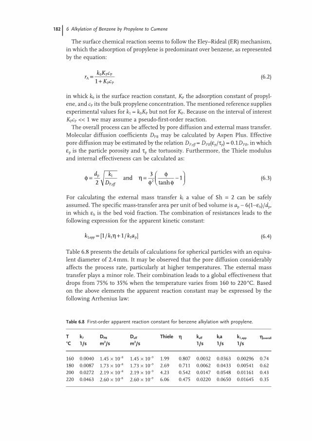
Table 6.8 presents the details of calculations for spherical particles with an equiva-lent diameter of 2.4 mm. It may be observed that the pore diffusion considerably affects the process rate, particularly at higher temperatures. The external mass transfer plays a minor role. Their combination leads to a global effectiveness that drops from 75% to 35% when the temperature varies from 160 to 220 ° C. Based on the above elements the apparent reaction constant may be expressed by the following Arrhenius law:
Table 6.8 First - order apparent reaction constant for benzene alkylation with propylene.
T k 7 D PB D eff Thiele h k eff k l a k 1,app h overall ° C 1/s m 2 /s m 2 /s 1/s 1/s 1/s
in which the reaction rate is given in kmol/m 3 .s and the activation energy in kJ/kmol. Table 6.6 enables an estimation of a fi rst - order reaction constant for the DIPB formation as:
k RT2 450 55000= −exp( / ) (6.6)
The above kinetic equations have been tested by the simulation of an adiabatic PFR. For an inlet temperature of 160 ° C, a benzene/propylene ratio of 7 and a spatial time WHSV of 10 a total conversion of propylene may be reached with selectivity around 90%. In conclusion, the kinetic data corresponds to a fast indus-trial catalyst and may be reasonably used in design.
6.3 Reactor/Separator/Recycle Structure
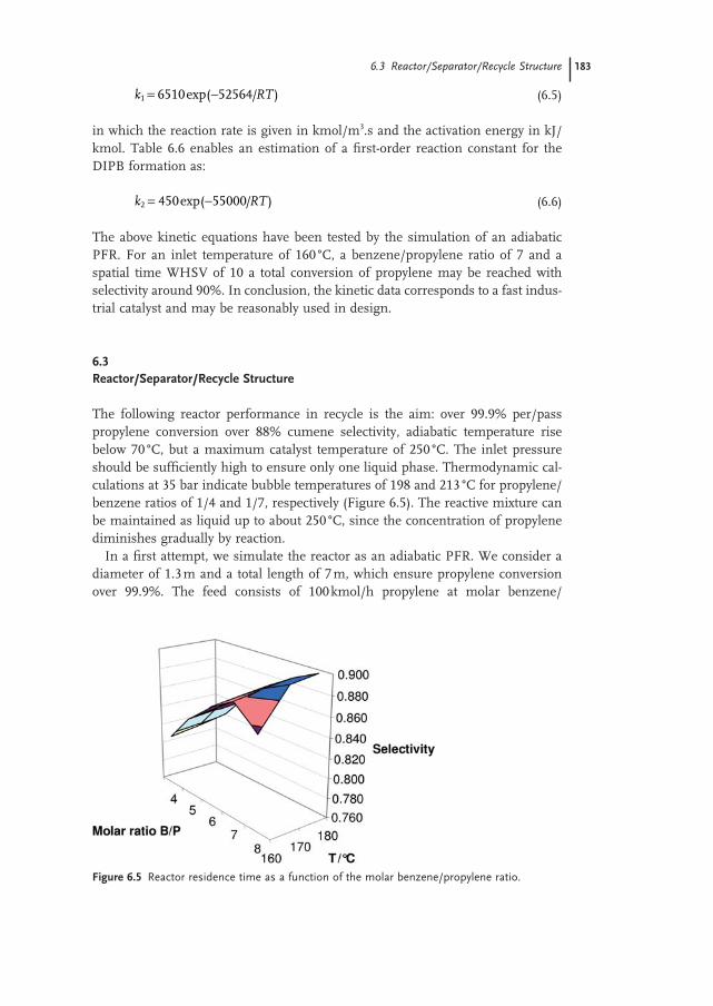
The following reactor performance in recycle is the aim: over 99.9% per/pass propylene conversion over 88% cumene selectivity, adiabatic temperature rise below 70 ° C, but a maximum catalyst temperature of 250 ° C. The inlet pressure should be suffi ciently high to ensure only one liquid phase. Thermodynamic cal-culations at 35 bar indicate bubble temperatures of 198 and 213 ° C for propylene/benzene ratios of 1/4 and 1/7, respectively (Figure 6.5 ). The reactive mixture can be maintained as liquid up to about 250 ° C, since the concentration of propylene diminishes gradually by reaction.
In a fi rst attempt, we simulate the reactor as an adiabatic PFR. We consider a diameter of 1.3 m and a total length of 7 m, which ensure propylene conversion over 99.9%. The feed consists of 100 kmol/h propylene at molar benzene/
Figure 6.5 Reactor residence time as a function of the molar benzene/propylene ratio.
6.3 Reactor/Separator/Recycle Structure 183
184 6 Alkylation of Benzene by Propylene to Cumene
propylene ratios between 4 and 8. The inlet temperature varies between 160 and 180 ° C. The reaction mixture may circulate downwards or upwards.
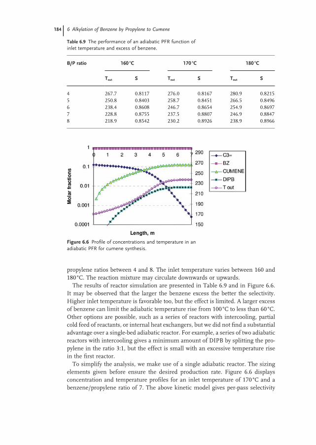
The results of reactor simulation are presented in Table 6.9 and in Figure 6.6 . It may be observed that the larger the benzene excess the better the selectivity. Higher inlet temperature is favorable too, but the effect is limited. A larger excess of benzene can limit the adiabatic temperature rise from 100 ° C to less than 60 ° C. Other options are possible, such as a series of reactors with intercooling, partial cold feed of reactants, or internal heat exchangers, but we did not fi nd a substantial advantage over a single - bed adiabatic reactor. For example, a series of two adiabatic reactors with intercooling gives a minimum amount of DIPB by splitting the pro-pylene in the ratio 3:1, but the effect is small with an excessive temperature rise in the fi rst reactor.
To simplify the analysis, we make use of a single adiabatic reactor. The sizing elements given before ensure the desired production rate. Figure 6.6 displays concentration and temperature profi les for an inlet temperature of 170 ° C and a benzene/propylene ratio of 7. The above kinetic model gives per - pass selectivity
Figure 6.6 Profi le of concentrations and temperature in an adiabatic PFR for cumene synthesis.
Table 6.9 The performance of an adiabatic PFR function of inlet temperature and excess of benzene.
of propylene to cumene of about 88%, in good agreement with the experimental data for MCM - 22 and beta - zeolite [7] , as well as a reasonable amount of DIPBs. The formation of secondary products reaches a plateau toward the exit of the reactor. The DIPB ’ s distribution is about 5% ortho, 40% meta and 55% para, with less than 0.3% oligomers. Dividing the total throughput by the amount of catalyst gives a weight hourly space velocity (WHSV) of 11, or a residence time of 5 min. These values are in good agreement with the industrial practice.
To increase the overall yield, the DIPB is reconverted to cumene in a transalkyl-ation reactor in the presence of a large excess of benzene. The same zeolite catalyst may be used. Practical data for the design are temperatures of 140 – 150 ° C, benzene/DIPB ratios between 20 – 30 and a WHSV of 2 to 3.
6.4 Mass Balance and Simulation
At the reactor outlet the reaction mixture has a temperature of 230 ° C and a pres-sure of 34 bar, the molar composition being 86.6% benzene, 12.6% cumene and 0.8% DIPB. Other components are lights , in this case the propane entered with the feed, and heavies , lumped as tri - propylbenzene.
By examining a list of physical properties in Table 6.4 , it can be seen that the freezing point cannot be exploited for separations. The relatively wide boiling points show good opportunities for separations by distillation. Note that if hexene forms by propane dimerization it will accumulate in the benzene recycle loop because its removal is very diffi cult.
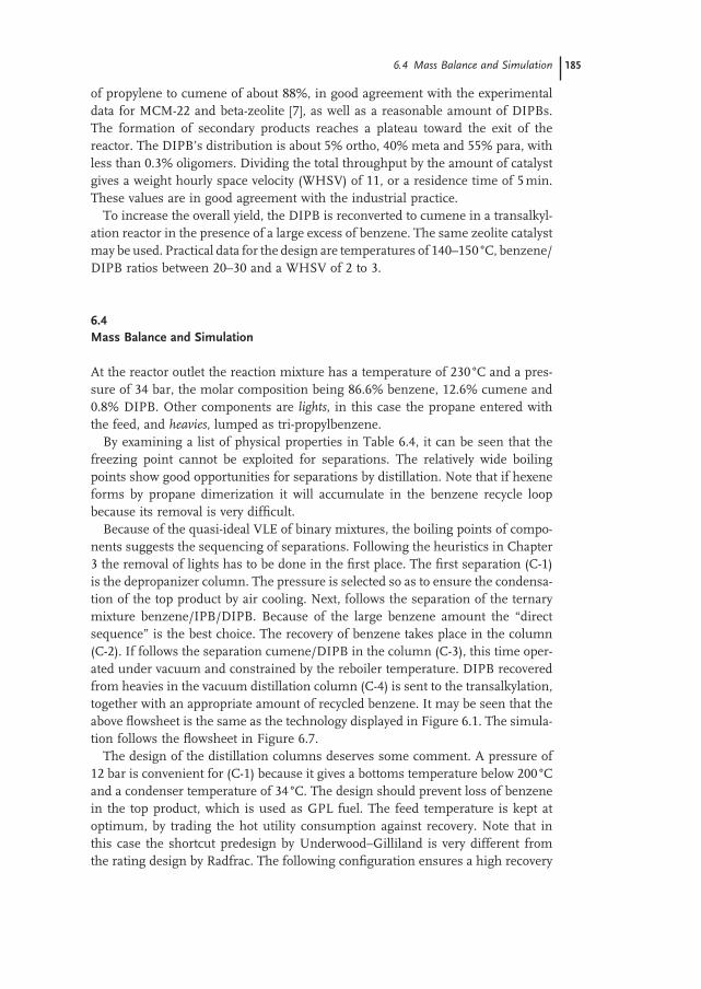
Because of the quasi - ideal VLE of binary mixtures, the boiling points of compo-nents suggests the sequencing of separations. Following the heuristics in Chapter 3 the removal of lights has to be done in the fi rst place. The fi rst separation (C - 1) is the depropanizer column. The pressure is selected so as to ensure the condensa-tion of the top product by air cooling. Next, follows the separation of the ternary mixture benzene/IPB/DIPB. Because of the large benzene amount the “ direct sequence ” is the best choice. The recovery of benzene takes place in the column (C - 2). If follows the separation cumene/DIPB in the column (C - 3), this time oper-ated under vacuum and constrained by the reboiler temperature. DIPB recovered from heavies in the vacuum distillation column (C - 4) is sent to the transalkylation, together with an appropriate amount of recycled benzene. It may be seen that the above fl owsheet is the same as the technology displayed in Figure 6.1 . The simula-tion follows the fl owsheet in Figure 6.7 .
The design of the distillation columns deserves some comment. A pressure of 12 bar is convenient for (C - 1) because it gives a bottoms temperature below 200 ° C and a condenser temperature of 34 ° C. The design should prevent loss of benzene in the top product, which is used as GPL fuel. The feed temperature is kept at optimum, by trading the hot utility consumption against recovery. Note that in this case the shortcut predesign by Underwood – Gilliland is very different from the rating design by Radfrac. The following confi guration ensures a high recovery
6.4 Mass Balance and Simulation 185
186 6 Alkylation of Benzene by Propylene to Cumene
Figu
re 6
.7 P
roce
ss - s
imul
atio
n di
agra
m f
or t
he a
lkyl
atio
n of
pro
pyle
ne w
ith b
enze
ne.
of propane with less than 100 ppm benzene: 16 theoretical stages with feed on 5 and a temperature of 150 ° C, and a refl ux of 4300 kg/h.
The recycle column (C - 2) is characterized by a very large distillate/feed ratio. Therefore, the design should minimize the reboiler duty. In addition, the pressure should be low enough to avoid excessive reboiler temperature. High recovery of benzene in top is desirable (over 99.9%) but small amounts of cumene are toler-ated. In a fi rst attempt we consider a column of 25 stages operated at atmospheric pressure, with feed location in the middle and a refl ux ratio of 0.26.
The column (C - 3) for cumene distillation operates under vacuum to avoid an excessive bottom temperature. A number of 30 stages and a refl ux ratio of 1.2 are suffi cient to ensure good - purity cumene with less than 100 ppm benzene.
In order to focus on the main issues of process integration, we disregard the distillation column for heavies, as well as the transalkylation section. A preliminary simulated fl owsheet in Aspen Plus [9] is shown in Figure 6.8 , with values of tem-peratures, pressures and heat duties. The fresh feed of propylene is 110 kmol/h. Note that design specifi cations are used for the fi ne tuning of the simulation blocks. The fresh benzene is added in the recycle loop as makeup stream so as to keep the recycle fl ow rate constant. This approach makes the convergence easier.
6.5 Energy Integration
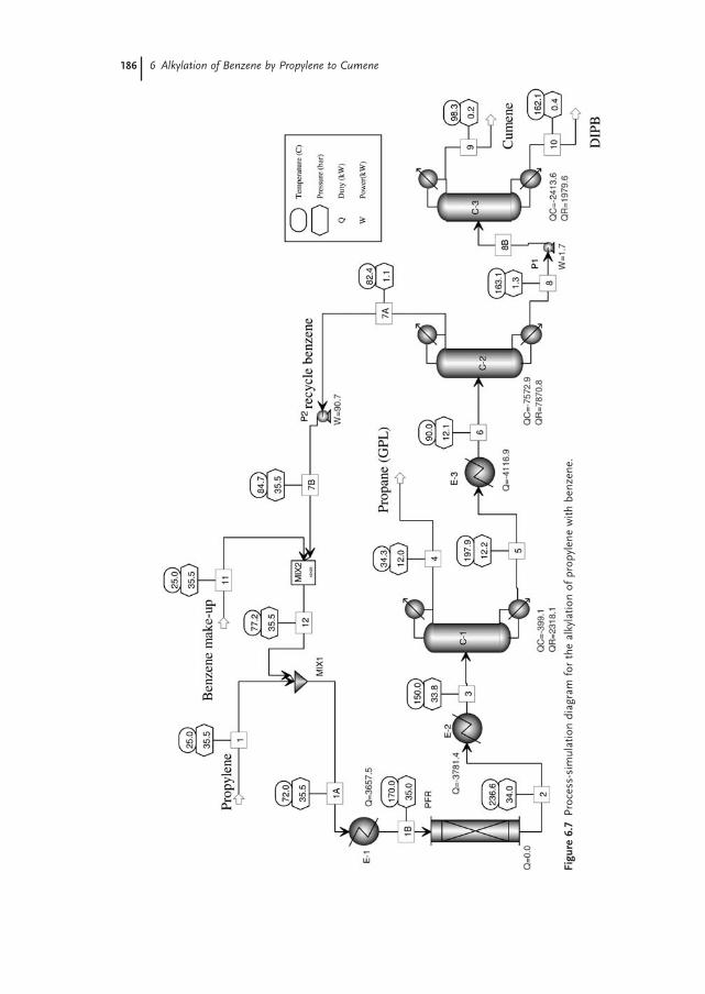
Based on the preliminary fl owsheet a table of streams for heat integration are built (Table 6.10 ). On this basis a pinch - point analysis can be done by using a special-ized software, such as SuperTarget [10] . In this way, targets for energy by can be determined for ∆ T min of 10 ° C, as shown in Figure 6.8 . The minimum energy requirements are Q h = 9143.4 kW and Q c = 11 063.9 kW. By taking advantage only from process/process heat exchange a saving in heat up to 43% in hot utility and 40% in cold utility can be achieved. Since the reaction is highly exothermal, we expect possible export of energy too.
6.5 Energy Integration 187
Table 6.10 Hot and cold stream table.
Cold streams Hot streams
Name T s ( ° C) T t ( ° C) Duty (kW) Name T s ( ° C) T t ( ° C) Duty (kW)
188 6 Alkylation of Benzene by Propylene to Cumene
The examination of composite curves indicates that the pinch is situated between the reactor and the benzene column. The largest energy consumer is by far the benzene column, with reboiler and condenser duties of more than 7.5 MW. By exchange between the reactor outlet and inlet streams considerable energy is saved, but only a modest amount of about 1 MW can be used for steam generation. The target temperatures of the hot streams (condensers) of the columns C - 2 and C - 3 show that most of the energy is rejected in the environment, at a temperature slightly below 100 ° C. In consequence, a fi rst design modifi cation is suggested: raise the pressure in columns so as to recover the energy of condensation in a more useful form, such as low - pressure steam. On the other hand, since the tem-perature difference top – bottom is large (about 80 ° C) the hot - utility temperature
Figure 6.8 Composite curves (left) and grand composite curves (right) in the preliminary analysis.
for driving the reboiler will set a hard constraint on the maximum column pres-sure. Obviously, the refl ux and feed temperature of the columns have to be optimized.
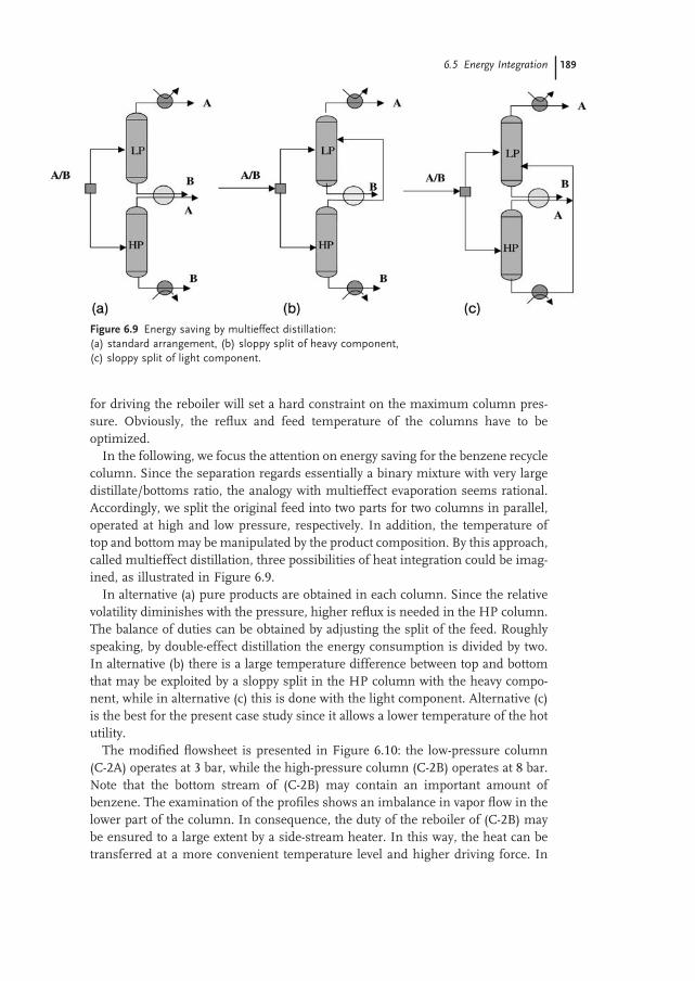
In the following, we focus the attention on energy saving for the benzene recycle column. Since the separation regards essentially a binary mixture with very large distillate/bottoms ratio, the analogy with multieffect evaporation seems rational. Accordingly, we split the original feed into two parts for two columns in parallel, operated at high and low pressure, respectively. In addition, the temperature of top and bottom may be manipulated by the product composition. By this approach, called multieffect distillation, three possibilities of heat integration could be imag-ined, as illustrated in Figure 6.9 .
In alternative (a) pure products are obtained in each column. Since the relative volatility diminishes with the pressure, higher refl ux is needed in the HP column. The balance of duties can be obtained by adjusting the split of the feed. Roughly speaking, by double - effect distillation the energy consumption is divided by two. In alternative (b) there is a large temperature difference between top and bottom that may be exploited by a sloppy split in the HP column with the heavy compo-nent, while in alternative (c) this is done with the light component. Alternative (c) is the best for the present case study since it allows a lower temperature of the hot utility.
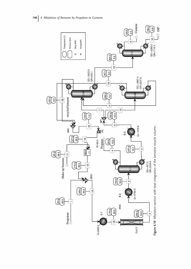
The modifi ed fl owsheet is presented in Figure 6.10 : the low - pressure column (C - 2A) operates at 3 bar, while the high - pressure column (C - 2B) operates at 8 bar. Note that the bottom stream of (C - 2B) may contain an important amount of benzene. The examination of the profi les shows an imbalance in vapor fl ow in the lower part of the column. In consequence, the duty of the reboiler of (C - 2B) may be ensured to a large extent by a side - stream heater. In this way, the heat can be transferred at a more convenient temperature level and higher driving force. In
Figure 6.9 Energy saving by multieffect distillation: (a) standard arrangement, (b) sloppy split of heavy component, (c) sloppy split of light component.
6.5 Energy Integration 189
190 6 Alkylation of Benzene by Propylene to Cumene
Figu
re 6
.10
Alk
ylat
ion
sect
ion
with
hea
t in
tegr
atio
n of
the
ben
zene
rec
ycle
col
umn.
the simulated fl owsheet the refl ux is identical in both columns at 0.26. The simula-tion shows that about 2660 kW may be saved by using the condenser of (C - 2B) as the reboiler for (C - 2A). Since the net distillate fl ow of C - 2A is larger, a supplemen-tary reboiler duty of about 560 kW is necessary. The net hot - utility consumption of benzene distillation drops from 7870 to 3794 kW, representing a saving of 51.8%. Furthermore, by slightly increasing the pressure in the column (C - 3) allows the generation of low - pressure steam. For both columns (C - 2) and (C - 3) the hot utility can be ensured by Dowtherm A or another similar thermal fl uid.
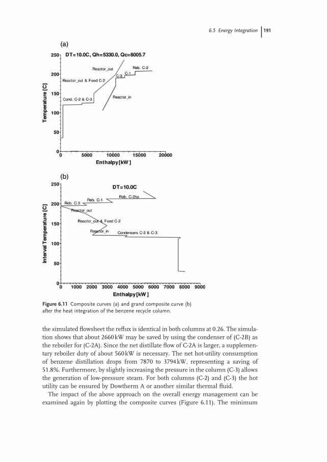
The impact of the above approach on the overall energy management can be examined again by plotting the composite curves (Figure 6.11 ). The minimum
Figure 6.11 Composite curves (a) and grand composite curve (b) after the heat integration of the benzene recycle column.
6.5 Energy Integration 191
192 6 Alkylation of Benzene by Propylene to Cumene
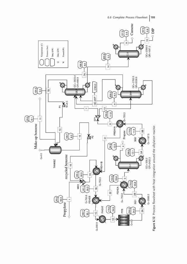
energy requirements are now Q h = 5330 kW and Q c = 8005 kW, much lower than before. But the salient element is that an amount of 2000 kW can be exported as process steam with a pressure of about 5 bar, as indicated by Figure 6.12 (right - hand). The reactor inlet may be matched against the reactor outlet and the feed to the column (C - 2). The heat available at higher temperature may used to generate medium - pressure steam. Figure 6.12 presents the fl owsheet with heat integration around the alkylation reactor that includes the preheater PREH1, feed - effl uent heat exchanger FEHE, and the steam generator SG.
6.6 Complete Process Flowsheet
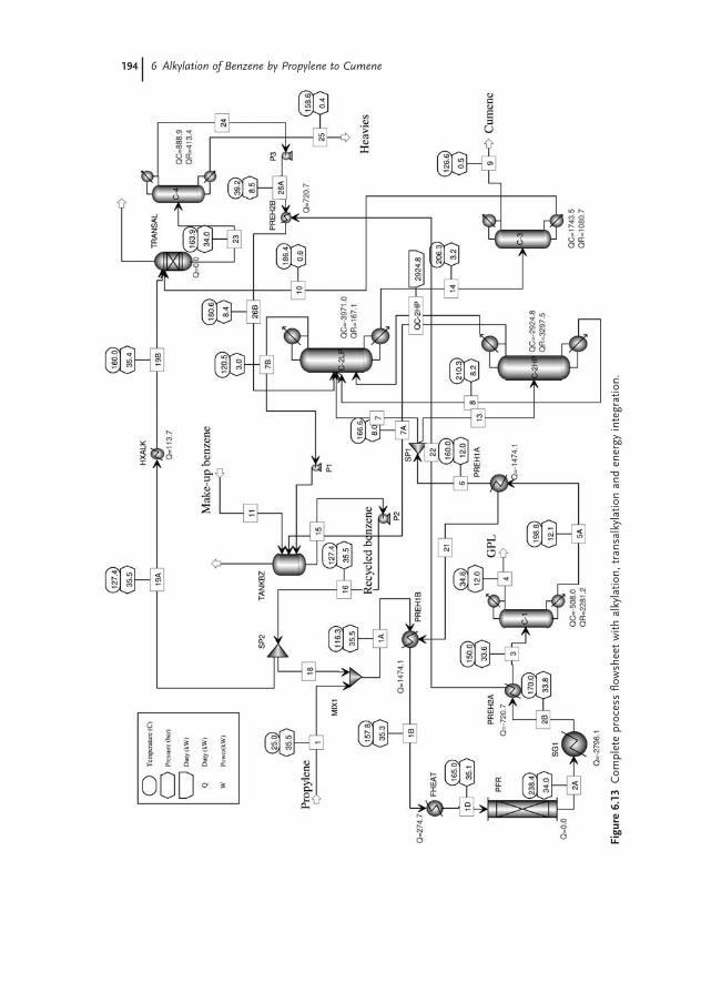
At this stage we introduce the second reaction step, the transalkylation of DIPBs in cumene. The fi nal process fl owsheet is presented in Figure 6.13 . The benzene recycle is split to achieve a benzene/DIPB ratio larger than 10. The same catalyst as for alkylation can be used at about 160 ° C. The transalkylation may be modeled as an equilibrium reactor. The equilibrium conversion is 90%, so that the overall yield in cumene can rise to over 99.4%. After the separation of heavies in the distil-lation column (C - 4) the mixture is directed to the column (C - 2LP). Note the pres-ence of a trim heater FHEAT for controllability reasons. Because of the two recycles of benzene, the feed preheating to reactors is split accordingly. The major part is taken by the heat exchanger for the alkylation section, the other for preheat-ing the benzene excess from transalkylation to the column (C - 2LP). In this way the duty of the reboiler of (C - 2LP) is lowered. The only stream available for MP steam generation is the reactor outlet. Because the net benzene recycle to alkyla-tion diminishes, the adiabatic temperature rise is higher. To keep a maximum of 240 ° C at the exit, the inlet reactor temperature has been reduced slightly to 165 ° C.
Some observations regarding the fl owsheet convergence should be mentioned. The convergence of the fl owsheet in Figure 6.13 with only benzene recycle is diffi -cult. To get convergence, the material balance around the distillation column (C - 2) should be fi nely adjusted. If the recycle of benzene is not of high purity, accumula-tion of cumene occurs, which in turn increases the amount of DIPB. When the transalkylation reactor is introduced, the fl owsheet convergence becomes easy and robust. In fact, we deal with consecutive reactions A P RB B → → for which multiple steady states may occur. The presence of back reaction R + A → 2P has a stabilizing effect on the plantwide material balance, as shown in Chapter 4 .
At the end of the project we can compare the energy values obtained in this project with the performance of commercial processes, as reported in Table 6.3 . The targeting procedure gives about 7600 kW hot utility for a production of 3.66 kg/s cumene, equivalent with 7600/3.66 = 2076 kJ/kg = 0.497 Gcal/ton. This value is close to the 0.6 - Gcal/ton reported for a modern process. The potential exported energy is given by the steam generated in SG1, condensers (C - 2LP) and (C - 3), in total 2796+3971+1743 = 8600 kW, or 2352 MJ/ton - cumene, which is
6.6 Complete Process Flowsheet 193
Figu
re 6
.12
Proc
ess
fl ow
shee
t w
ith h
eat
inte
grat
ion
arou
nd t
he a
lkyl
atio
n re
acto
r.
194 6 Alkylation of Benzene by Propylene to Cumene
Figu
re 6
.13
Com
plet
e pr
oces
s fl o
wsh
eet
with
alk
ylat
ion,
tra
nsal
kyla
tion
and
ener
gy in
tegr
atio
n.
equivalent to 1090 kg steam/ton - cumene (steam of 3.5 bar has an enthalpy of vaporization 2150 kJ/kg). This value is double compared with the 525 kg/h steam at 3.5 bar in Table 6.3 .
It is useful to re - examine the position of the optimum benzene amount in recycle after performing the heat integration. We can defi ne as an objective the minimization of a “ loss function ” that includes the cost of DIPB (reconverted to cumene), plus the cost of hot utility in the recycle column, minus the value of the raised steam:
The optimization variable is the fl ow rate of the recycled benzene. As a constraint, the outlet reactor temperature is limited at 250 ° C. The fi rst term decreases, while the second and third terms increase with higher B/P ratio. As a numerical example, we consider the following prices: 72 $ /kmol (600 $ /ton) cumene, 0.150 $ /kWh hot utility (high - temperature thermal fl uid), as well as 0.015 $ /kWh for the generated LP steam. The Aspen Plus optimization routine fi nds an optimum at a B/P ratio around 7. Note that the optimum is rather fl at, but also very sensitive to prices. For lower values of the hot utility (probable) the optimum shifts to the high B/P bound, in this case 10. This analysis demonstrates that the reaction selectivity toward the main product is the key optimization variable.
6.7 Reactive Distillation Process
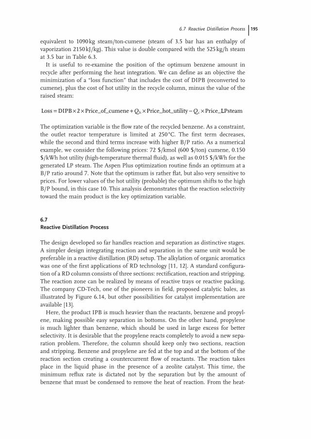
The design developed so far handles reaction and separation as distinctive stages. A simpler design integrating reaction and separation in the same unit would be preferable in a reactive distillation (RD) setup. The alkylation of organic aromatics was one of the fi rst applications of RD technology [11, 12] . A standard confi gura-tion of a RD column consists of three sections: rectifi cation, reaction and stripping. The reaction zone can be realized by means of reactive trays or reactive packing. The company CD - Tech, one of the pioneers in fi eld, proposed catalytic bales, as illustrated by Figure 6.14 , but other possibilities for catalyst implementation are available [13] .
Here, the product IPB is much heavier than the reactants, benzene and propyl-ene, making possible easy separation in bottoms. On the other hand, propylene is much lighter than benzene, which should be used in large excess for better selectivity. It is desirable that the propylene reacts completely to avoid a new sepa-ration problem. Therefore, the column should keep only two sections, reaction and stripping. Benzene and propylene are fed at the top and at the bottom of the reaction section creating a countercurrent fl ow of reactants. The reaction takes place in the liquid phase in the presence of a zeolite catalyst. This time, the minimum refl ux rate is dictated not by the separation but by the amount of benzene that must be condensed to remove the heat of reaction. From the heat -
6.7 Reactive Distillation Process 195
196 6 Alkylation of Benzene by Propylene to Cumene
Figure 6.14 Catalytic distillation column for cumene synthesis.
recovery viewpoint the pressure should be selected to get the highest possible temperature in top. From the reaction viewpoint the temperature should favor both the reaction rate and the desired selectivity. Better selectivity is obtained at lower temperature (see Table 6.6 ). The above aspects are contradictory and a com-promise has to be found.
If, from the heat - saving viewpoint the advantage of reactive distillation over fi xed - bed reactor technology seems obvious, from reaction - engineering viewpoint there are some physical constraints that may be seen as disadvantages. Firstly, when a reactant is highly volatile the driving force for reaction in the liquid phase is diminished by the vapor – liquid equilibrium. This is the case with the propylene. The reaction rate is about r IPB = kx B Py P / K P , in which P is the column pressure and K P is the VLE constant of propylene, As a result, the concentration of the propylene in liquid at the operating pressure (11 bar) is about an order of magnitude lower with respect to the fully dissolved gas at higher pressure (25 bar). Secondly, the fl ow of reactants and products in the countercurrent favors the formation of sec-ondary polyalkylation species with respect to a cocurrent PFR. This negative effect on selectivity is amplifi ed by the fact that in a RD setup the amount of benzene is limited by the optimum refl ux rate needed for heat integration.
Therefore, adopting the solution of reactive distillation instead of separate reac-tion and separation units does not lead automatically to a more effi cient process. Matching the conditions of separation and reaction in the same device requires careful design. The element with the highest impact is the chemical reaction. The key condition for an effi cient and competitive process by reactive distillation is the availability of a superactive catalyst capable to compensate the loss in the driving force by phase equilibrium, but at the same time ensuring a good selectivity pattern.
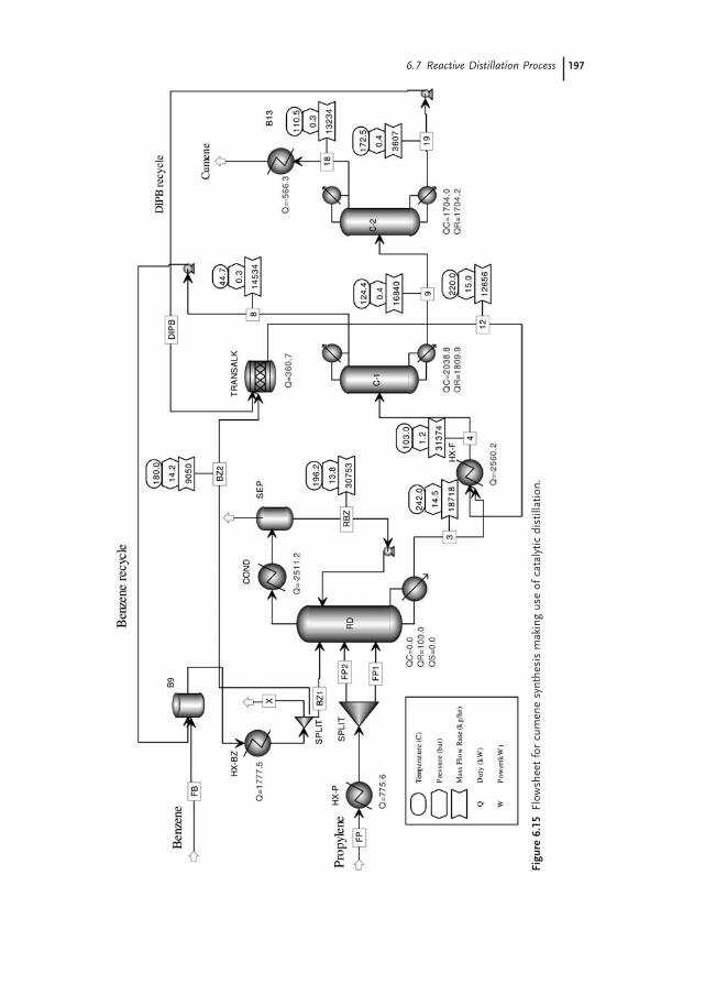
Figure 6.15 presents a compact fl owsheet based on catalytic distillation, as simu-lated with Aspen Plus TM [9] . Benzene and propylene are fed in countercurrent in
Figu
re 6
.15
Flow
shee
t fo
r cu
men
e sy
nthe
sis
mak
ing
use
of c
atal
ytic
dis
tilla
tion.
6.7 Reactive Distillation Process 197
198 6 Alkylation of Benzene by Propylene to Cumene
a RD column, the propylene feed being split into two parts. The column is designed for total conversion of propylene. The top vapor consisting essentially of nonreacted benzene is condensed and sent back as refl ux. The mixture after reac-tion is further treated in the columns (C - 1) for separating the excess of benzene and in (C - 2) for separating the cumene and DIPB. Both columns operate under vacuum at about 0.3 bar. DIPB is sent to transalkylation and to be reconverted to cumene.
As a numerical example we consider a column with 39 reactive stages each of 1 m 3 holdup. The pure propylene feed of 110 kmol/h split into two equal parts enters the column on plates 20 and 35. This operation takes better advantage of the propylene concentration and offers better temperature control. Benzene is fed on the top stage in excess of 60% above the stoichiometry. This excess is necessary mainly to limit the temperature in bottom, but helps the selectivity to IPB too. Taking into account the refl ux around the column, an overall benzene/propylene ratio larger than fi ve may be realized. The following kinetic data are used in simu-lation [14, 15] :
Cumene formation P B0.7 with exp: . ( / )r k C C k RT1 1 1
62 6 10 77000= = × − (6.7)
DIPB formation with expP IPB: . ( / )r k C C k RT2 2 262 0 10 80000= = × − (6.8)
with the reaction rate in kmol/m 3 s, concentrations in mol/l and energy of activa-tion in kJ/kmol.
A pressure of 14 bar gives a good compromise between the above aspects. The RD column is simulated as reboiled stripper with reactive stages. Although the highly exothermic reaction should make unnecessary the use of a heat source, we consider just a small reboiler to prevent residual propylene entrained in the bottom. For this reason, few reactive stages below the low feed of propylene are useful.
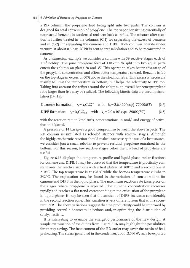
Figure 6.16 displays the temperature profi le and liquid - phase molar fractions for cumene and DIPB. It may be observed that the temperature is practically con-stant over the reactive sections with a fi rst plateau at 200 ° C and a second one at 210 ° C. The top temperature is at 198 ° C while the bottom temperature climbs to 242 ° C. The explanation may be found in the variation of concentrations for cumene and DIPB in the liquid phase. The maximum reaction rate takes place on the stages where propylene is injected. The cumene concentration increases rapidly and reaches a fl at trend corresponding to the exhaustion of the propylene in liquid phase. It may be seen that the amount of DIPB increases considerably in the second reaction zone. This variation is very different from that with a cocur-rent PFR. The above variations suggest that the productivity could be improved by providing several side - stream injections and/or optimizing the distribution of catalyst activity.
It is interesting to examine the energetic performance of the new design. A simple examination of the duties from Figure 6.16 may highlight the possibilities for energy saving. The heat content of the RD outlet may cover the needs of feed preheating. The steam generated in the condenser, about 2.5 MW, may be exported
as steam of 6 bar. Very low pressure steam may be raised in (C - 2) and upgraded by compression to ensure the heat for the column (C - 1). The high - temperature hot utility is needed only for the vacuum distillation columns.
In conclusion, compared with the previous design the fl owsheet based on reac-tive distillation appears to be more economical as hardware and more effi cient from an energy - integration viewpoint. However, the premise of feasibility is the availability of a catalyst with superior properties in terms of activity and selectivity compared with those used in a liquid - phase reactor.
6.8 Conclusions
An effi cient process can be designed for the manufacturing of cumene by the alkylation of benzene by making use of zeolite catalysts available today. Simple adiabatic reactor technology is appropriate, but the operating pressure should be suffi ciently high to ensure only liquid - phase reaction. To limit the formation of byproducts by consecutive polyalkylation a large ratio benzene/propylene is used, which in turn implies large benzene recycle and considerable energy consump-tion. The energy spent for benzene recycling can be reduced considerably by heat integration, namely by double - effect distillation. In addition, the heat developed by reaction can be advantageously recovered as medium - pressure steam. The performance indices of the conceptual design based on literature data are in agree-ment with the best technologies.
A modern alternative is the use of reactive distillation. At fi rst sight appealing, this raises a number of problems. The reaction rate is considerably reduced with respect to a homogeneous liquid process because of the lower propylene concen-tration due to phase equilibrium. In addition, the countercurrent fl ow of reactants
Figure 6.16 Temperature and concentration profi les in a catalytic distillation column.
6.8 Conclusions 199
200 6 Alkylation of Benzene by Propylene to Cumene
and products favors the formation of secondary polyalkylation species. Therefore, catalytic distillation becomes economically interesting only if a suitable catalyst is available. This should ensure much higher activity and better selectivity compared to a liquid - phase process. If these conditions are fulfi lled the catalytic distillation is superior by more compact equipment and better use of energy.
3 Wallace , J.W. , Gimpel , H.E. ; The Dow - Kellogg Cumene Process, in Meyer ’ s Handbook of Petroleum Refi ning Processes , McGraw - Hill, New York, USA , 2nd edn , 1997
4 Perego , C. , Ingallina , P. , Recent advances in the industrial alkylation of aromatics: new catalysts and new processes , Catal. Today , 3 – 22 , 2002
5 Degnan , T. F. , Smith , C. M. , Venkat , C. R. , Alkylation of aromatics with ethylene and propylene: recent developments in commercial processes , Appl. Catal. A;
General , 221 , 283 – 294 , 2001 6 Perego , C. et al. , Experimental and
computational study of beta, ZSM - 12, Y, mordenite and ERB - 1 in cumene synthesis , Microporous Materials 6 , 395 – 404 , 1996
7 Corma , A. , Martinez - Soria , V. , Schnoeveld , E. ; Alkylation of benzene
with short - chain olefi nes over MCM - 22 zeolite , J. Catal. , 192 , 163 – 173 , 2000
8 Ercan , C. , Dautzenberg , C. Y. , Barner , H. E. , Mass - transfer effects in liquid - phase alkylation of benzene with zeolite catalysts , Ind. Eng. Chem. Res. , 37 , 1724 – 1728 , 1998
9 Aspen Plus, release 10, Aspen Technology, Cambridge, Massachusetts, USA
10 Super Target, release 5, Linnhoff - March, Northwich, UK
11 Smith , L.A. , US Pat, 4,849,569 , 1989 ; US Pat, 5.446.223 , 1995
12 Hsieh et al., US Pat, 5.082.990 , 1992 13 Krishna , R. , Hardware selection and
design aspects for reactive - distillation columns, in Reactive Distillation, status and future directions , Sundmacher , K. and Kiele , A. (eds.), Wiley, New York, USA , 2003
14 Han , M. , Li , X. , Lin , S. , Intrinsic kinetics of the alkylation of benzene with propylene over beta zeolite catalyst , Kinet.
Catal. , 42 ( 4 ), 533 – 538 , 2001 15 Han , M. , X. Li , S. Lin , Theor. Fund. Chem.


![The localization and adsorption of benzene and propylene ...modem.ucsd.edu/htjcadd/publications/paper/55.pdf · cumene in the MWW structure [11,12]. It has been found that the diffusion](https://static.documents.pub/doc/80x56/608449fe997baf3125519106/the-localization-and-adsorption-of-benzene-and-propylene-modemucsdeduhtjcaddpublicationspaper55pdf.jpg)
