+ All Categories
Home > Documents > ALL MODE ACTIVE FILTER

ALL MODE ACTIVE FILTER

Date post: 13-Mar-2022
Category:
Upload: others
View: 9 times
Download: 0 times
Share this document with a friend
5
HOBBV ELECTRONICS ALL MODE ACTIVE FILTER MODEL AF-SOSK •••• •••• •••• •••• CW, SSB, AM, FM""i"-CO)-'E:-r't::t:,·-·-c !#Eff, -lf'1r' • fiF'Wffl0)4;r..7"- ::l·7?717'@1Jflr(: J:oc - .-''A.&cf-''1,..{;;r,.71 /:./-:rf-71 Jl/7f-O>f!t Jl! "('PJJHJ'll'J[ 0> --!i:rn ;1;r lfHIH-t. e CWW'.Jl!O) L ow- Q · 4A. 7" - F ,..{A.7?717 ' @1 lfltt:J: 1J ') r- YL"-!i:rn l :fHIH-t. . .. •PLL r- /j-"::i - ?' - @llfltt:J: IJ, ', 'r-YL"-!i:rn (AF-606KO)b) t:$<tm!L -c' ·.t:-t. - MODEL AF-406K ••• ••• ••• , .... . :iE::tl SPECIFICATIONS MODE NOTCH Center Frequency Wi dth SSB High Pass Low Pass 2.5kHz 2.0kHz .l.SkHz cw (Band Pass) Center Frequency Width PLL Center Frequency Lock Range lnput Voltage Tone Frequency Input Max Nominal Po,,;er Output Max Power Source Voltage Consumpsion Dimensions Net Wei ght AF-606K AF-406K 300-3,000Hz 50-600Hz at Fo=750Hz -2octB 500Hz - 6dB 12dB/ OCT 2.500Hz - l OdB 12dB/ OCT 2.000Hz - lOdB 24dB/OCT 1.500Hz - l OdB 36dB/ OCT 500- l.200Hz - 170Hz -3dB 140Hz -3dB 140Hz -3dB llOHz -3dB llOHz -3dB 80Hz -3dB 80Hz -3dB 500- l ,200Hz - 70Hz - O.l-2V - ' 500-2.SOOHz - 4V(2W) 2V (0.5W) 1.7W/ 8Q DC13.8V(l2- 15V) 200mA 150W x 62H x 150Dmm lkg
Transcript

HOBBV ELECTRONICS

ALL MODE ACTIVE FILTER MODEL AF-SOSK

~-&

•••• •••• •••• ••••• •

• CW, SSB, AM, FM""i"-CO)-'E:-r't::t:,·-·-c !#Eff, ~·- r, -lf'1r' ,..f:;FO)~i!f, iJirn~~~LT~~fJ[hi'liltJ.t:-t.

• fiF'Wffl0)4;r..7"- ::l·7?717'@1Jflr(: J:oc- .-''A.&cf-''1,..{;;r,.71 Jl/7f -O)*Jll;..{';-~L"31iftj'j!-11J~ /:./-:rf-71 Jl/7f-O>f!t Jl! "('PJJHJ'll'J[ 0> ~' --!i:rn ;1;r lfHIH-t.

e CWW'.Jl!O)L ow- Q · 4A. 7" - :/fflli&'.f(iif~>~-:; F ,..{A.7?717' @1 lfltt:J: 1J ') :.--~-:.--?'O).p~, ·S/NltO)~ ' -cwrn-~~lill~.l!XIJ~-t',

r - YL"-!i:rn l:fHIH-t. . . . • PLL r-/j-"::i - ?' - @llfltt:J: IJ, CWrn~~:t-:iltJ-CS/NltO)~' ',

[lf)~.J!XIJ ~-t- 'r-YL"-!i:rn ili ~IH-t. (AF-606KO)b)

•ff'ifO)~' •9cm;r..~·-n-~?"-A.J:mi t:$<tm!L -c' ·.t:-t.

- ":"~

MODEL AF-406K

• ••• • ••• • ••• , .....

:iE::tl SPECIFICATIONS

MODE NOTCH Center Frequency Width

SSB High Pass Low Pass 2.5kHz

2.0kHz .l.SkHz

cw (Band Pass) Center Frequency

Width

PLL Center Frequency Lock Range lnput Voltage Tone Frequency

Input Max Nominal

Po,,;er Output Max Power Source Voltage

Consumpsion Dimensions Net Weight

AF-606K AF-406K

300-3,000Hz 50-600Hz at Fo=750Hz -2octB 500Hz - 6dB 12dB/ OCT 2.500Hz - l OdB 12dB/ OCT 2.000Hz - lOdB 24dB/OCT 1.500Hz - l OdB 36dB/ OCT

500- l.200Hz

- 170Hz -3dB 140Hz -3dB 140Hz -3dB llOHz -3dB llOHz -3dB 80Hz -3dB 80Hz -3dB

500- l ,200Hz -70Hz -O.l-2V -

' 500-2.SOOHz -4V(2W) 2V(0.5W) 1.7W/ 8Q DC13.8V(l2-15V) 200mA 150W x 62H x 150Dmm l kg

<AF-SOSK> <"'':..-""'':Acf>·C.·l!l;.1uu111!l

Bandpass Freq. Control . ~11:.!J1'/,;;7"-:S'­

Pilot LED

· v11»:A1' .,7 Line Switch

PLL Free·run Freq. Control

(FJG.l)

~Ee Positive

8Negative~!!:=:==:~~;::'= ' DC13.8V

Ei:).Positive 8 7 - ?iM 8 Negative White line

••• •••• •••• , •••• @

I PLL!ll:t:/L-:9-~-/Ul)I PLL Tone freq. adjust ~/ .,7i.;i;~U1!l

Notch Band Width Adjust

~7:..-:;;...-,1"\-Q')tf.IS~t.::"-1'-il7-""

RCA Plug Shielded wire To a External Speaker jack of a transceiver.

~ I~ ~ ;;;11~'1'1!Ht 11-JaY i:ll~'l'-llltt 7-:>.lll

(FIG.2) Soldered To ground of a transceiver.

11~: Jf>:fll!O)-.lt i'-/.11. 'telE:ft~nt.:U'iiilt (DC) 13.8V1:'. ;;£ir.f'ff:IJ1:200mAU . l-.0)!,0):b'·~· ::&§-r--t. it ml0)1ti!i!lfl7"7 ?'/::r- n•f!l!»J L L"YHlfl-.ll:i~ Hf Y ?",;- ~@c:tfi*'1L:l: -t.

AC7?"7"?--!:f!l!lfl-t ol~~l1. :;E~~l±DCI2V. ":itiilt200mA 1:'. ~ft?JJ' lf\ 1J»'tl:l±:b1DC15Vi:J.r0)1,0)-!:fi!lfll L"(f.:'~•·. ~ilf.i/P,::IJ11i:l+.:b'. DC t ISVUJ-.0) l,0)-!:fll!ff!L;l:-t ~;js::il:b'/;'.{~t;\-t o.:~:b';i;IJ :l:T. (FIG.I l

91-'8i!Al::'-:IJ-: $1-;'l!l::<.t"-71--!:f!l!HfT ot~~ l1. t";...-7"7?' ~-?ltt.::/-1v n!R-r'. $1-ffll::<.t"-7J- Y?"7f-@ ....... {!l;~ L:l:T0 1;...-1::"-?";...-::<.8QO)::<.l::0 -

7J-:b'.i!&L ·n ·:l:T.~;; Yr ·:1f-®:1::•;;777·-!:t&!*XL:l:Tl:IAJJl!l::<.t"-7J-l;t fJJ IJl1~~t1;l:-t0

1t~A.1J: ~7 ;...-::,. - 1 <- ( ·~@:II) 0)$1-$::<.l::"-"1-lli ::1J ~t";...-7"7?'-!:-?I ltt.:::.--1vf*-ftl-c' .Ajj Y?-71-@ ....... tU~UT. (FIG.2) @~7;...-y-1<·-0) ...... ·:1~·:t;-;...-/l\n ....... tUxL L"bfi!ff!l:IHUT:b'. ;js:.llO)~i~

::<.1·:17:b'OFFO)~C:::<.t"-7J- (f'-Jiiif. 7}llfl.ft'*'1~t) :b'JIJl'FL1.C• •;Ji::b';i; HT.

"-·:11-";f<-;...-: "7 ~·:t;-;...-0)7"7?'-!:PHONE:/"\"7?®" ~LiZ>h:l:T. ::<.7 v.:tffl . ~ /71vflf t't,<?1:'bfi!ffl1:'~;1:-t. PHONE::l"\"7?" 7"7?'~~Li2> hiT~::<.t"-71-~fJJIJ~~~tl.;I:~

•AF-606K···~- r- ::<.1 7 7C:.J:IJNOTCH7-( Jv? - . SSB1 <;...- f 1~::<.·7 -1 '"?- (tf -;tf lfl). CW1<;...- f 1 ~::<. •7-f 1v?-(t"-?·7-11v?-l&lFPL L~-;...-- r::r-?"?:fJJ~:dT.

•AF-406K···~- f · ::<.··b7c:.J:IJNOTCH7-! 1v?-. SSB1<;...-~· 1(::<.·7-1 Jv?- (tf )iftlf). CW1 <;...- ~· ,(::<.•7-( 1v?- (t' -?•7-( 1v?-)~~;t :l:T.

'e iffi:ll!l~l;t~7;...-:;;-, <- (·~f.1.'tl~-r'l'f• •;l:T. (AF-il06KO)PLL:f.::J::.­a/l;t~~:l:T. l

NOTCH···/77· 711v?-11·~ 1.1ifc:~;l:tl.ol::'-H\'~O)-~Lf.:~-;...­O)V;;tftf i.-llll 'J~<t.:11>c:f4!ffl LiT.

• h7131ill<:'J:~n<l)(300Hz-3kHz iif~) O),;J..,.~i.-IQ>..,(IJlt!IL L"V;'"Jfif:b' ilUl-t <>l~iJi'.c:-t·;1~L;t-t.

• / ·:17·1lH .. u11~@0)•;,'7 ~H.Ut1J(uJl:l!!U T !:~UT o lt.l iJ:tfl:O) llJ :b'~ i<~'> ;I: T. ~;t<L T~ ;1:1" U·:1+l.lliJ:lc.~J!l!l:b'LC:< <~'> ;t-t. (FIG.J)

• /·:1'1-·7-1 w?-11SSB. CW. PLLO)T..-.<L"O)~- ~'1'.'lhlt-Li-t. Iii!. fflLT.t• ·~~11..l:;Je(!).@O)-?;l:h~ilt:liluJC:• •..,1.:;\ -t:lt!IL L"i>·~ ;t-t.

10

20

50

60

(RG.3) NOTCH FILTER

I I

I

I

/

/

,,. /

-f--NatTOW

I I

I I

I_\,_~ I I Min

1- wa 1, 1,

I

Max

10L-~~~~~~~~~~~~~~~~~~~~~~---'

7 10'

frequoncy(Hz)

(RG.4) sse BAND PASS FILTER

10

20

HiilhPHS

50

60

10L..~~~~~~~~~~~~~~~~~~~~~~--' 10'

freQIAf'CY (Hz)

;t h7-i.;i;l.'1Ul!l

(AF-406K)

._'l> I ~/r I ~ :;z: cp{.'}!J;~tt!Jl!l

Bandpass Freq. Control

Notch Band Width Control

®11~;l:··b7-

U,"-·, t-';j;- /:/1'·,7 Phone Jack

Line Switch

SSB···-1:{J·Ji1:1£ 1tl.oj!!;I~/1 A'& l.fr.i'.l.ftf.iO)ViW1:.t oif:jl~/1 A'~~ '.J..'~-tt ot.:11-'.>t:f!!!ffl L1T0 " 1 / f ;<.·711i.-:$t- (500Hz) l:c-/ f 7..·711i.-:$t­(2.5kHz, 2kHz, I.5kHz) O)*llfi- h-tt1:.t9iifl~'llH.!l! rtJ ~-tt1<L ·n -I.To (FIG.4)

CW···CWO)!ji- r-/ O)l;. {- iifl~ ~-tt of!'il<'.> -C ... JO)-!tl_\ -711i.-:$t--('To y ;..-!if;..-?" ~JllJ~ot.:11-'.>t:QO)J!!:\ '/<;..- r /f ::<.(1:.· - ?> 711i.-?1- {-4fJtfi!m L, -C ~ 9170Hz (AF-606Klil40Hz) b• t;SOHz 1-(' O)iifl;e'j'11f l.!l!-l-:iiURT o.:l:tJr' -('HT.

• /<;..- 1-· /f::<..P-t.•ffilil:U'IWll~@<soo-1,200Hziif~l v .... ~~~L -c~fli: ih':lil:*<=t..:ofJJ:li'.c-t?rUT. JJo\ -11. flll1'l!lt9~T\ -1-- ;..-1:-t7J­L. '.ffli:iitJ'l&*l:f.i:o~1:1-7;..-::,--/«- ('.fFd:lll 0)-f- .:i.-.::.;..- ?'~l{J(

91T. ((FIG.5)

@S/N.J:tO)Qil<'.>-C!!\\ -ffi'.}-('li. / 1 A'lil<;~1:.t9 Y ;..-~;..-?'tJ1go.:l:tJ1Jj9 1T • .:O) .t7t..:1:1'1iii~ftfl.!l!O)~\ -:r-,;;::,-,,;..-..-...w~HT.

PLL(AF-606KO)l;.J- ··CWffi''.}O) I-- / l:PLLr-/r·::z-:$t°- 0)7 Y-7/Jali1:U'ItJ'-ttU.:l:1'1: . LOCKnt~ili7JtJ'~1:LLOCK1/::/'r-?l

- QJW.#.*TL1 To .:O)LOCKffi''.}ili tJ-(' :t-:r 1 :t~l!lii>~ltli'f.l~-tt-Cft O)CWfli:'.} !:fiil(.;ff'.}~:jlj:1:L -C~9. /1;<.'!,7.x.- ::J/?'!,l,t\" ?Y7t..:CW '.ffo{tJ'-('HTo ( FIG.7)

• cw~-n:-c, cwra%tJ'Ril*1:t..:o.t71:/.-;..-1-· /{::<.l:ililli:tt~~®v ...,~~~LI.To

ePLL7Y-7/ffi!iltfl:@·:n~~~~L. LOCK1 ;..-:J>r-?l-@tJ'ff.~ 1: .#.*TT otll:fli't:-t71'l1To

@J-7 ;..-::,--, <- (~ffi'ftt) 0)*-7' 1 *If'. tJ b1 'J' ~\ •!:LOCKtJ'tJ·trt;T,i:( T,t 9. *-1'1"if1Tl:LOCK·!iflJ!l:b1~:111-,-C•if&tfftl!.O)tiI~1:.t9LOCK 1" o.:1::111/)91.T. A.:IJ;G:l.Eli!V(O.IW/SQ) :11 1ia~-('T. ('it:jjO)~~ /~)

0

10

20

30

40

50

60

1...-:1;-PLL 1--;..-7'::z-?l'lill~11, ~- 1-··7..1 T rtJ'!:'O):f-:J;,-,,;..-1:t..:..,-c\ ·-c t,;'7;1:j)J(j!L 'C\ ·;t-t"O)-('fil!lfl LT..:\ -!: i!r liPLL 7')-7/l~iJ:Uti:Jlt!l@'/..., ~-rlt.'fJt:J;lnJ\ ,..,1,t\ -1:.\tfL -C~H-t.

(FIG.7)

®:9l-llll11~'/7·, ~ DC Socket

• •••• •••• •••• , .....

(FIG.5) CW BAND PASS FILTER

Min Max

10' Frequercy( Hzl

(FIG.6) PLL TONE DECODER

7 lo'

F-y(Hzl

Lock lndocat0<

CW Signal

~nd Pass 1--'-0u"'tou"-t-...1 Pll Flit• Tone Decoder

Lock Sign11 Output

Powa Amp. SptokOi'

Free Run Freq. Control Tone Freq. Volume Control

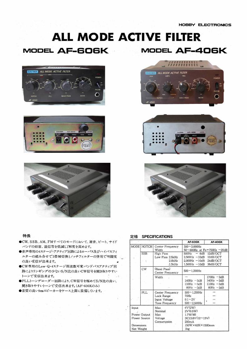
• All mode active filtering removes interference on the desired signal and improves readability in CW, SSB, or AM modes.

• The All Mode Active Filter consists of four active circuit stages as well as low pass and high pass filters for clear reception.

• For CW reception, a four stage, low Q variable frequency band­pass circuit is included to provide clear CW reception with high SIN ratio.

• A PLL (Phase Locked Loop) Tone Decoder for noise-free recep­tion.

• A 9 cm diameter speaker is also included.

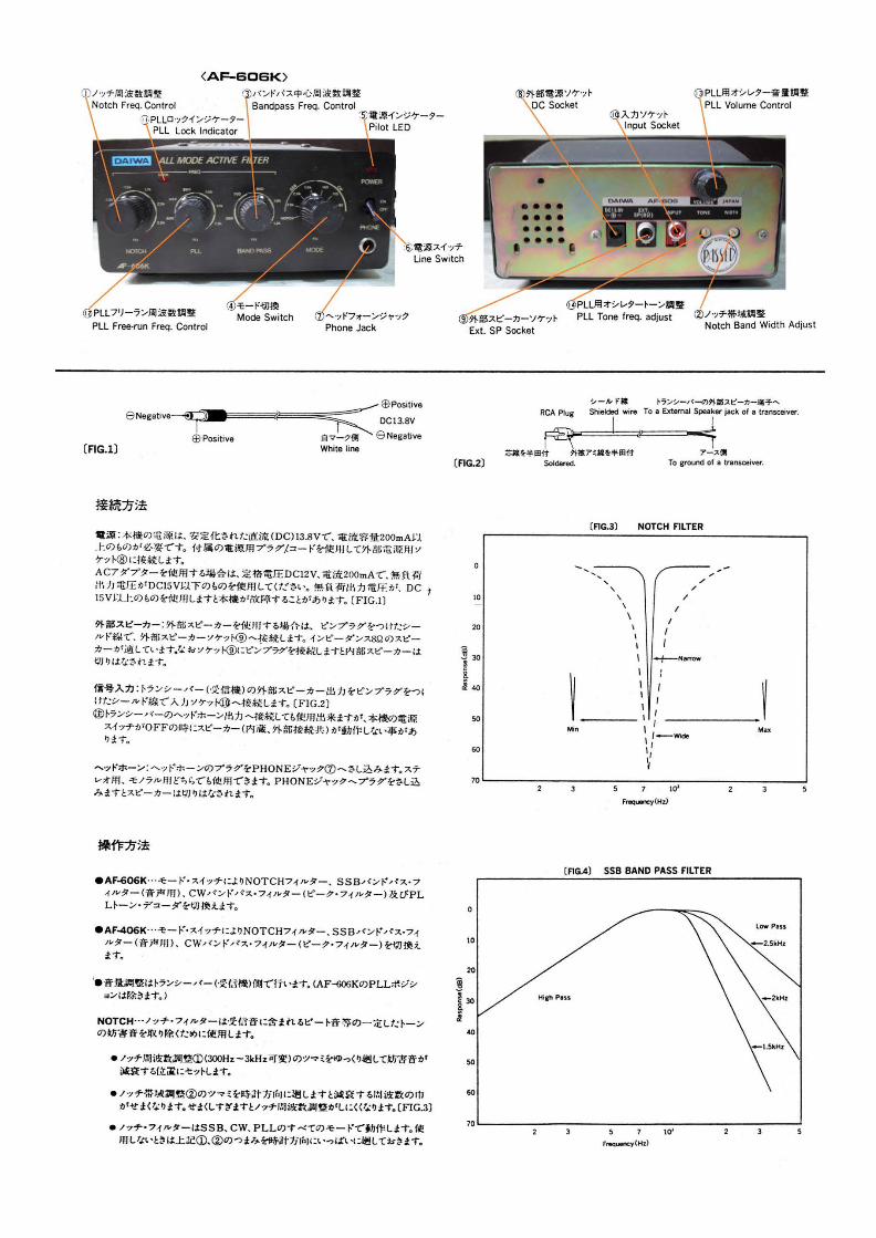
CONNECTION: Power Supply - A power supply of 13.8 VDC (200 ma. min.) is re­quired for the operation of the All Mode Filter. Connect your power supply to the external DC socket with the DC power cord supplied.

When using an AC adapter, make sure the maximum output voltage (with no load connected) is below 15 VDC.

External Speaker - An external speaker (8 ohms) can be connected to the socket with a RCA pin plug. The built-in speaker is disabled whenever the external speaker is connected.

Input Signal - Connect a shielded cable with a RCA pin plug to the input socket and to the speaker terminals of your transceiver/receiver.

The headphone socket of your transceiver/receiver can be used as a signal source, but the normal speaker of your transceiver/receiver will be disabled. The output signal level from the built-in speaker of the AF406K/ AF606K may be somewhat low when the power switch of the filter is in the OFF position.

Headphones - Connect a stereo or mono headphone to the Phone Jack. The built-in speaker of the AF406K/ AF606K is disabled whenever a headphone is used.

OPERATION: • AF606K - Select either the Notch, SSS-Bandpass filter, CW

Bandpass filter (Peak filter), or the PLL Tone Decoder mode.

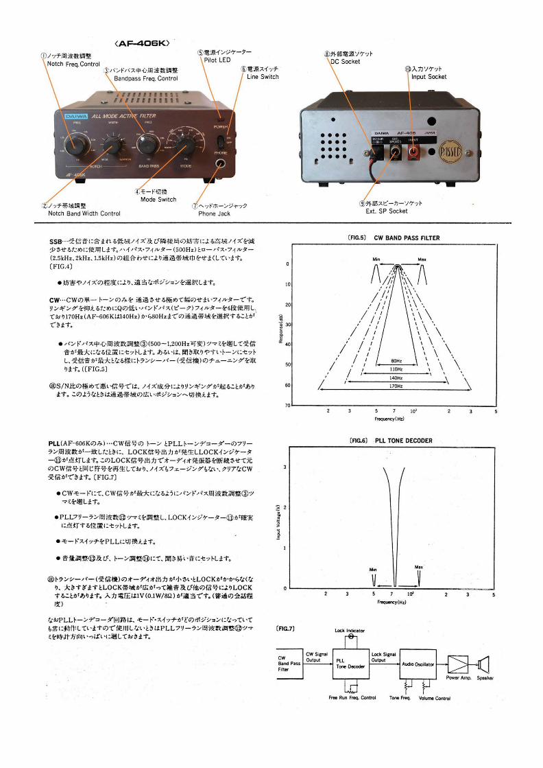
• AF406K - Select either the Notch, SSS-Bandpass filter, CW Bandpass filter (Peak filter).

• Notch - The Notch Filter supresses "beat interference" on the desired signal.

(A) Turn the notch frequency control (300-3 kHz) slowly until you reach the position ~here the interference is reduced.

(8) The bandwidth of the notch filter will narrow as the Notch control is turned clockwise.

(C) The notch filter is operable with all modes. (SSB, CW, PLL) Turn both knobs (I) and (2) to the fully clockwise position whenever you do not desire the notch filter function.

SSB Filter - Low frequency noise or hum (around 50-100 Hz) caus­ed by a signal on an adjacent frequency can be reduced with the SSB Filter. The filter consists of highpass and lowpass filters. (2.5, 2, and 1.5 kHz.) Select the proper position according to the level of interference.

CW Filter - The CW filter is a very narrow bandwidth filter designed to pass only the desired CW signal. For "ringing" supression, the All Mode Active Filter employs a four stage low Q bandpass (peak) filter. A 170 Hz. (140 Hz in the AF606K) to 80 Hz. bandwidth can be selected.

• Adjust the Center Frequency of the Bandpass Filter Control (500-1200 Hz variable) and then set the frequency of the received signal for maximum reception quality. On the other hand, you may wish to adjust for the desired tone and then peak the receive frequency of your transceiver/ receiver for best reception.

Pll {AF606K only) - When the tone frequency of the CW signal and the free-running frequency of the PLL Tone Decoder are the same, a locked signal output is generated in the PLL circuitry and the LOCK indicator will glow.

The locked signal output keys an audio oscillator which then reproduces the received CW signal. The PLL reproduced CW signal is free of interference caused by noise or fading.

• In the CW mode, adjust the Bandpass frequency control to obtain maximum output of the desired CW signal.

• Adjust the PLL free-running frequency control until the LOCK indicator is .on.

• Set the mode switch to the PLL position.

• Adjust the volume control and the Tone oscillator frequency control.

The required input level of the PLL Tone Decoder is I v (.I w/8 ohm). (The sound level at . I watt is almost the same as normal human conversational levels) When the input signal level from your transceiver/receiver is too low, the PLL will not activate. On the other hand, the PLL can be activated by unwanted signals or noise when the input signal level is excessive. Please make sure the output of your transceiver is adjusted to the proper level.
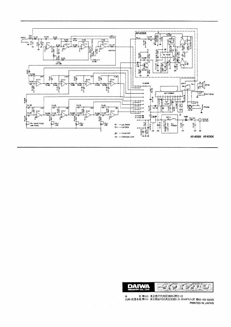
IC• ·-)IA 3404

ICl.1 ·-LM 324

,JI- -F<.M C»'

1:';. I x • i ~ ~ L----------~-------~

··""""

-0. CHr1111H

~I

SPIO

OC'IJ.IV (1t-1$V)

-ii- ---CERAMIC CAP AF-406K AF-606K

DAIWA .-nn'CO .. LTD.

* u e 101 Jto;·:r.n-tt1±111u•rn PJ•r2-12 ~Ldii•"i-'t-m*ml "1!>141 lfOj\tll,\i',J ll (Ri!§liJXl:H2-31-9~39'1::~"2F ft03-493-I68lift)

PRINTED IN JAPAN


Recommended