SHORT FORM CATALOG #5 64 CONTENTS Var iable FlilelS 2 } '3 Octave Filters 4 Random Noise Sources 5 Equalizers 6 Analyzers 7 Multiple Frequency Oscillator 9 Automatic tnspection Unit 9 Instrumentation Modules 10 New Product Announcemer1ts 12 Special InslJuments 14 In Development 15 Noise Interference Measurement 16 Decibel ConversJon • Voftajle 16 • Pel ce nt 17 ASA Standard Preferred Frequencies 18 Allenuation pad Oeslgn Data 19 ReprBsentali ves 21
Transcript
SHORT FORM CATALOG 564
CONTENTS Var iable FlilelS 2 3 Octave Filters 4 Random Noise Sources 5 Equalizers 6 Analyzers 7 Multiple Frequency Oscillator 9 Automatic tnspection Unit 9 Instrumentation Modules 10 New Product Announcemer1ts 12 Special InslJuments 14 In Development 15 Noise Interference Measurement 16 Decibel ConversJon bull Voftajle 16
bull Pel cent 17 ASA Standard Preferred Frequencies 18 Allenuation pad Oeslgn Data 19 ReprBsentali ves 21
INSTRUMENTS OF QUALITY
Continuously Variable Passive Filters
Spectrum Equalizers
Spectrum Analyzers
Modular Amplifiers
Random Noise Sources
Automatic Inspection Units
Multiple Oscillators
Instru mentation Modules
Custo m Instru mentation
Pr()fea JepelJaabJe in years of Jertice
Allison Laboratories Inc PO BOX 515 LA HABRA CALIFORNIA 90631
Model 201 series 2
VARIABLE FILTERS wide dynamic range
no internal noise
flat pass bands
steep co ntinuou s attenuation
negligible ringing effect
SERlES 2 The Model 2 Series are variable passive network filters with indepe ndent hi gh cutoff and low cutoff se c tions Each section has a ran ge swi tch tha t changes the cutoff in OCt I V(gt te ps lUI a vem ilr dial that tlUHS liver a range of ()J IP
octave The a ttenu ati on ratl is m dh per octave an d lilP) nray he (scadcd for increased a tten ua tion Two fi llkrs give 60-70 db per I)c ta vP Thegt mo()I h pass band is fl a l i1 db over olO of the pass band It Ina) be tuned to a handshy
width as narrow as 1 middot DClavC The
maximum in put voltage is 2 vol is The input and output impedance is 600 oh ms
Size 7middot ll hi gh 7J i deep 17J 1 w ide
Rack model is mounted on a 7 panel with 6 1 behind panel
Rack mount is the same price and shipping weight for ]1 models
Add 150 of the standard unit price for hermeti cally sealed capacitor~
T Y Dlcal C u -v e r--rr-shy v [ lAiJ I 1
MODEL 20 1 The new Model 201 extends into the sub-audio range while retaining all of the desirable characteristics of the 2 se rie s such as excellent transient hanshydling capability ability to handle small signal parameters and no active eleshyments The low noise low distortion and good transi e nt handling capacities of this filter make it excellent for studi es of low level transient phenomena s uch as encountered in heart studies geophys ical work th emocoupleR and low frtmiddotqu ency vi brations Wi th high cutshyoff onl y the filter will pals DC to the cutoff frequen c
chart reClding into cps
i th e
provided multipli( r
on the dial
pane l direc
for tl y
Low cutoff sect io n bullbullbull 1 to J28 cps High cu to ff secti on 2 to 256 cps
Size 7middot IJ high 17middotl i wide 7middot1 i deep Rackmoun t 7 hi gh 19 Wide 6middot l i deep
201 Sh WRt 35 S725 201 R Rack Moullt Sh Wgt 35u $725
Hermetic Capacit ors Not Available
l lllli l l l Y li I I I++J-l 0
I -I TI I I 91 -r+-W--++-r--~
- 0
0
2
Model 420 Model 460 Typical Filter
Designed as an inexpensive general purpose filter for laboratory and proshyduction use the 420 is very simple to operate and is direct reading with a single knob control for each section covering a range from 20 to 20000 cps A selector is provided for switchshying the filter out low cutoff only high cutoff only or band pass mode of operation There is 20 db or more attenuation per octave for the first octave wi th attenuation outside the pass band exceeding 25 db at all frequencies beyond an octave away from cutoff frequency Minimum bandshywidth - approximately h octave Maxishymum input-2 volts Impedance-600 ohms
Portable - excluding knobs and handle (Shown) 17 long 5~3 deep 8 high
Available also in rack mount case with 7 x 19
panel and 5middot~~ behind the panel
TYPICAL CURVES
10
D I o ~ l O
~ 0 o ~ 0
60
----shy
-
1 ~ II
JJ
V 70 1 1 tI l I(
FPfOU EN C1
Curve 111-1 Model 420
6 e 10K
Curve 112-2 Model 420 Filters in Series
420 Sh Wgt 2411 $385 420R Rack Mount Sh Wgt 3011 $385
3
This filter also features the single knob tuning The rejection band may be moved continuously over the range of 20 to 20000 cps The reject band is slightly less than 1 octave wide at the -3 db points Attenuation at the bottom of the reject band varies as shown in the curves below It can be used to eliminate single components as intershyfering hum the resonant peak of an accelerometer a fundamental or conshystant tone to facilitate analyses of the remaining frequency spectrum Filters used in series eliminate ditional frequencies
460 adshy
Impedance bull 600 ohms Reject band Less than 1 octave wi de
Maximum input 2 volts
Portabl e 17 long 5middot deep 8 high
Available also in rack mount (Shown with 7 x 19 x 5middotyenI)
TYPICAL CURVES
0
3 ~7 I
sect) I
10 50 100 OO 1000 SODa 0000 FR tOUfNC (
460 Sh Wgt 2411 S395 460R Rack Mount Sh WgL 3011 $395
IMPEDANCE MATCHING
TRANSFORMERS These units are used for applications where it is inconvenient to match impedances of 600 ohms The AL-483 Input Transformer is an autotransformer designed to work from approximately 10000 ohms to the 600 ohm circuit of the filter The AL-484 Output Transshyformer is designed til malch the 600 ohms impedance of the fll ter into the grid of Il vacuum tulx~ or a VTVM The output transformer has an impedance ratio of 600 to 45000 ohms A tershyminating resistor transformer to the filter
pis hui lt roperly
into tenni
the nate
Each transformer is encased ih a mushymetal case and a grounded steel case
In the event that high impedance inputs are required in frequencies above or below the above limits refer to the Model 659 amplifier These units have input impedance of 40000 ohms and match the filter using a 600 ohm series resistor The frequency coverage can be extended in this manner from 10 cps to 500 kcps
AL-483 Input Autotrans 10000600 ohms $35
AL-484 Output Trans 600 ohmsGri d 535
FIXED 13 OCTAVE
FILTERS Fixed 113 octave filters having exshycellent and uniform response Each model consists of 1 decade of 10 filters case complete with power supply
These are passive networks using solid state isolation and amplification
Standard filters are on iSA preferred (()Ilter frltqllencies Special fllters may be ordered to other frequencies and down to 5 bandwidth Individual filter s are also available cased or un ca sed as desired
TYPICAL CURVE ALL FIL TERS
5 6 J 3 rc
Il
O
40
so
MODEL FREQUENCY PRICE
240 25 - 20 $2850
241 25 - 200 1500
242 250 - 2000 900
243 2500 - 20000 850
244 25000 - 200000 850
Individual filters by quotation
See also 13 octave analyzer page 8
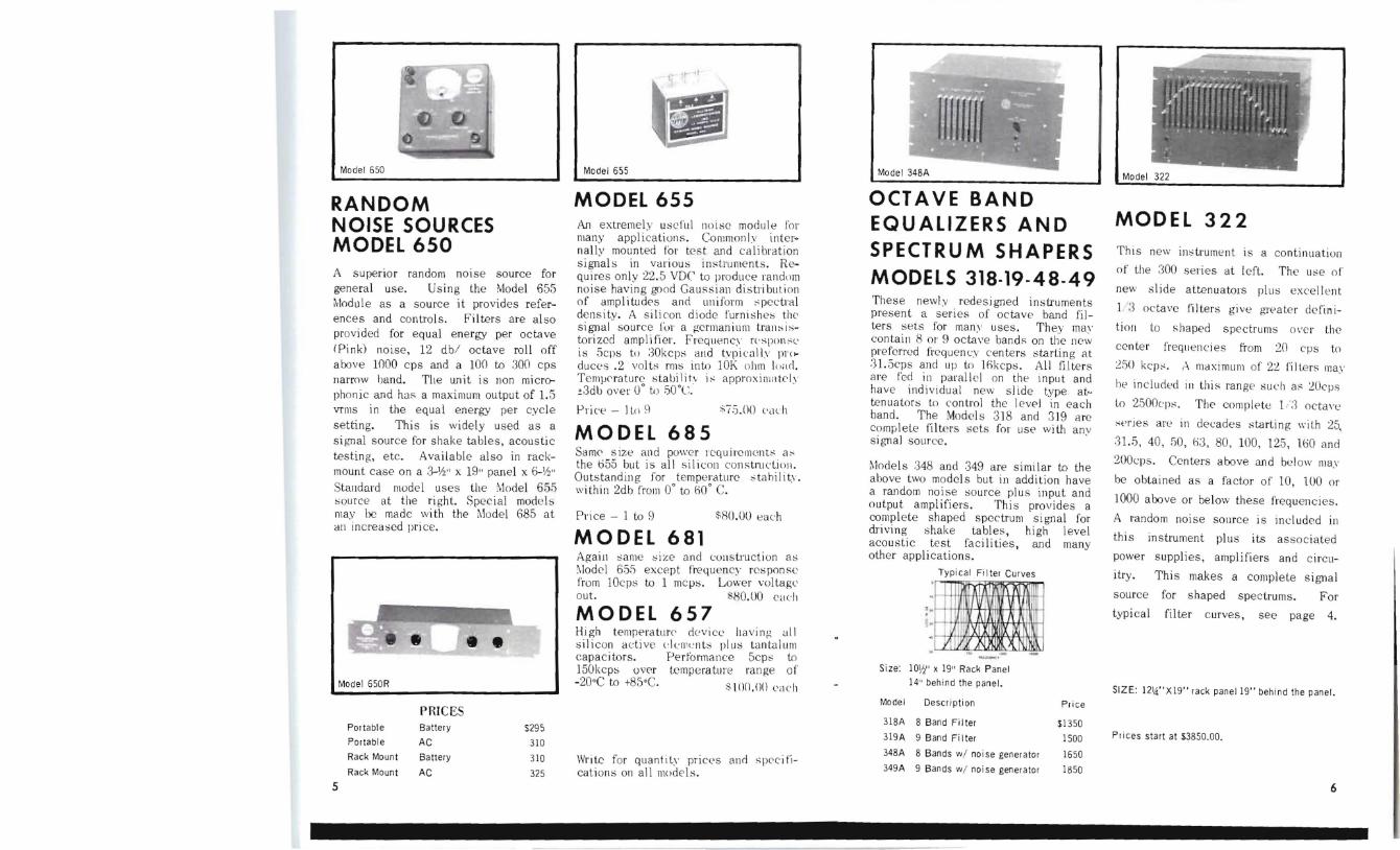
Model 650
RANDOM NOISE SOURCES MODEL 650 A superior random noise source for general use Using the Model 655 Module as a sou rce it provides refershyences and controls Filters are also provided for equal energy per octave (Pink) noise 12 db octave roll off above 1000 cps and a 100 to 300 cps narrow band The unit is non microshyphonic and hnf a maximum output of 15 vrlllS in the equal energy per cycle setting This is widely used as a signal source for shake tables acollstic testing etc Available also in rackshymount case on a 3-Ih x 19 panel x 6-112 Standard model uses the Model 655 ~ource at the right Special mode may be made wi th the ~lode l 685 at an increaed price
Model 650R
Po rtable
Portab le
Rack Mount
Rack Moun t
$295
310
310
325
PRICES Battery
AC
Battery
AC
t 1
III Model 655
MODEL 655 An extremelv useful Iloise module for many applications Commonlv int e rshynal lv mounted for tes t and calibra tion signal s in variou in struments Reshyquires on ly 225 VDC to produce randllm noise havin g good Gauss ian distli butioll of amp I i tudes and ulli form spectral density A s ili con diode furnishe~ the signal sou rce fu r a german ium transisshytorized ampli fler Frequency rls[lon l is 5clls to 30kcps and tvpicnll pr(~ duces 2 volts rms into 10K ohm Id Templtrature stabilih is applOximatc ly ~3db over 0deg to 50degc
Price - lo 0 ~75 ()O lICh
MODEL 685 Samlt size and power rcquirellwnt1 as the 055 but is all si licon constnlClioll Outstanding for temperature stahili ty wi thin 2db from 0deg to ti(f c Price - 1 to 9 $R(lOU each
MODEL 681 Agaiu same size and construction as llodcl 655 except frequency response from lOcps to 1 mcps Lower voltage out sHOOO Clt1ch
MODEL 657 High temperaturl device having all silicon adive (dcll-nts plus tnntnlum capac itors PertcJnname 5cp to J50kc ps over tempe rature range of -20degC to +85degC s10000 elt1ch
Write for quantity pricls and specifishycations on all models
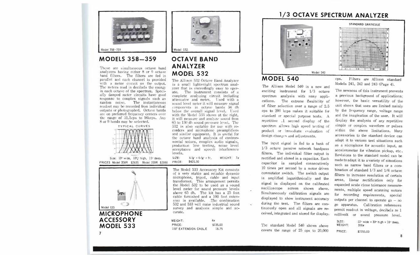
OCTAVE BAND EQUALIZERS AND SPECTRUM SHAPERS MODELS 318middot19middot48middot49 These newly redes igned instruments present a series of octave band filshyters sets for man uses They may contain 8 01 9 octave bandf on the new preferred frequency centers starting at 315cps and LIP to Jok eps All fllte rs are fed ill parall e l on the inpu t and have individual new s lide type atshytenuator~ to control the Ievel in each band The Ytode s 3 l B and 3 J9 a rc complele filtpls sets for USE with any si gnal source
Models 348 and 349 are simi lar to the above two model s but in addition have a random noise source plus input and output ampli fiers This provides a complete shaped spectrum si gnal for driving shake tables high level acoustic test facilities and many other appli cations
Typical Filter Curves
lJ I J A iri)( 1-- i
l H IJ I t~ il I I M
1 _ A li I
Size lOW x 19 Rack Pane l
14 behind the panel
Model Desc ript ion Pri ce
318A 8 Band Fi Iter $1350 319A 9 Band Fi Iter 1500
34BA 8 Bands wi noise generator 1650 349A 9 Bands wi noise generator 1850
bull bull bull bull bull bull I -I -
Model 322
MODEL 322
This new intrument IS a continuation
of lhe 300 series at left The ue o f
new slide atten uators pillS excellen t
1 1 octave filters give gItater definishy
tion to s haped spEctrums oe r the
cente r frequencies from 20 cps to
250 kep ma ximul1l of 22 fi Iters may
1)( included ill this range such a 20cps
lo 2500cp The complete 13 oetac
spries are in decades sta rlin g wilh 25
315 40 50 03 80 100 125 HiO and
200cl1s Centers above and below may
he obtained as a factor o f 10 100 or
1000 above or below these frequencies
A random noise source is included in
this instrument plus its associated
power supplies amplifiers and ci rcushy
itry This makes a complete signal
source for s haped spectrums For
typical filter c urves see page 4
SIZE 121iXI9 rack panel 19 behind the panel
Pr ices start at $385000
5 6
1
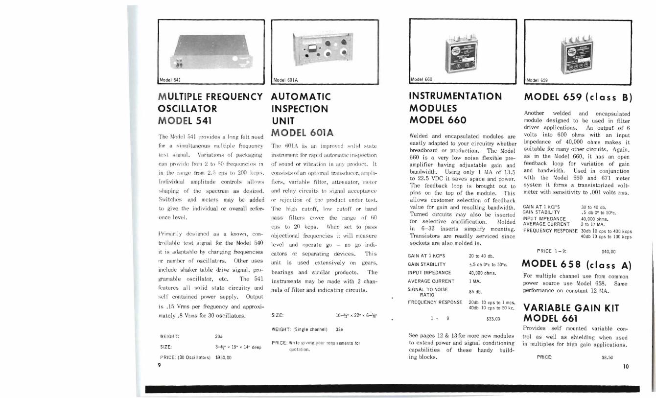
Model 358-359
MODELS 358-359 Thce arC simultaneous octave band analyzers having either 8 or g octave hand filters The filters are fed in parallcl and each channel is provided with a me ter circuit on the output ThE meters read in decibels the energy in each octave of the spectrum Specishyally dampld meter circuit have good reponsc to complex sign a l such as mndom noise The instantaneo us reado ut rna be reco rded from individual uutput or photographed Octave hculCjs are on pre ferred ficquen lY centClij oer th( rallge of 315cps to 16kcJlb II V
8 vr g bands muv h se l f~c ted
TYPICAL C URVES
~
Si ze 19 wi de 101j hi gh 15 deep
PRICES Model 358R $2635 Model 359R S2990 ~
Model 533
MICROPHONE ACCESSORY MODEL 533
Modelmiddot532
OCTAVE BAND ANALYZER MODEL 532 The Allison 5a2 OctavE Band Analyzer is a small lightweight spectrum ~lllttlshyyzer that is exceedi ngl) easy to op~rshyate The intl1lmcnt consi sts of il
complete ana lyz ing c ircliit including attenuator and metlL I ed wi th a sound level meter it wi ll mcasun signal compOIlPnts in octan bands Sri db helow the overal l ignai Iend l -ed with the ~l()dei 5n shol] at the right it ill mCaurC and lIlahzlt lt)lI nd from (i5 tu n(l dh soulld PI( sure le vel The 532 is also suitable for lISl with rCshycordcri and microphonC preampl ilkr and si milar equipment It is useful for the octave hand amdvsis of environshymental noic~ cOl1lplex audio signal ploductiuLl acceptance levels
line and
testing speech
noise level interference
SIZE 6middot x 6middotJA x 5 WEIGHT 711 PRICE $42500
The Model 533 Accessory Kit consists of a very stable and reliable dynamic microphone tripod cable and input transformer This arrangement permits the Model 532 to be used as a sound level meter for sound pressure levels above 65 db The kit has a 25 foot cable fumished and a 100 foot exten sion is available middotThe combination 532 and 533 will make industrial sound survey curate
MODEL 540 The Allison Model 540 is a new and exciting instrument for 113 octave spectrum analysi s wi th many applishy
cations The extreme flexi bi Ii ty of of fil ter selection over a range of 25 cps to 200 kcps makes it suitable for standa rd or special purpose tests A repetitive 1 second display of the
spectrum allows high speed te ~ ting of product or imnllJiate ( aluation of design chan(s CUld adj ustments
The input signal is fed to a hank of
113 octave passive network bandpass filters The individual filter output is rectified and stored in a capacitor Each capacitor is sampled consecutive ly 10 times per second by a motor driven commutator switch The switch output
is amplified logarithmically and the
signal is displayed on the calibrated oscilloscope screen shown above Simultaneously calibration signals are
displayed to show instrument accuracy
during the test The filters are Conshytinuously open and all signals are reshy
ceived integrated and stored for display
The standard Model 540 shown above covers the range of 25 cps to 20000
cps Filters are Allison standard Models 241 242 and 243 (Page 4)
The newness of this instrument prevents a previous background of applications however the basic versatility of the unit shows that uses are limited mainly by the fmquency range voltage range and the imagination of the user It will display the analysis of any repetitive
simple or complex waveform or pulses ithin the above limitations Many accessories to the standard device can adapt it to various test situations such as a microphone for acoustic input an accelerometer for vibration pickup etc Revisions to the standard model can be made to adapt it to a variety of situations such as narrow band filters or a comshybination of standard 113 and 116 octave
filters to increase resolution of certain areas linear rectification only for expanded scale close tolerance measureshyments multiple speed scanning motors for recording requ irements special outputs per channel to operate go - no
go apparatus Cal ibration references permit readout in voltage decibels re 1 millivolt or sound pressure level
SIZE WEIGHT
22 wide x 30 high x ]8300
deep
PRICE $725000
8 7
Model 541 Model 60lA Model 660
M ULTIPLE FREQUENCY OSCILLATOR MODEL 541
The orill )4] provides a long fe lt need
for ltl si mullaneous multiplE frequen c~
tc~t si Ipoundl lill ar iations of packagilJgshy
call pr () v id(~ fmll ] L to )() frequ c ncins in
in tillt rg frolll 2 cp~ 10 200 kq)
Individual amplitude controls all nws
sllUping of the spectrum as dei red
S~ i tehes and meters may be added
to give thE individual or overall refershy
ence level
Primaril y deil-rn ed as a known conshy
trollable test signal for the Model 540
it is adaptabl e by changing frequencies
or number of oscil la tors Other uses
include shaker table drive signal proshy
(Tamable oscillator etc The 541
features all so lid s tate circuitry and
sel f contained power supply Output
is 1 5 Vrms per freguency and approxi shy
mately 8 Vrms for 30 oscillators
WEIGHT 20
SIZE 3--Ji x 19 x 14 deep
PRICE (30 Oscill ators) $95000
9
AUTOMATIC INSPECTION UNIT MODEL 601A 1111 1)01 i~ all illlpr()middotcmiddotd solid stille
in s tMlIlwnt for rapid automatic in plctinn
of ollnd or vihration in iUI ~ produ c t It
cOflil-qfan (Jptional tfH lI dl rclmiddotr amp lishy
fi er variahl flll cgtr attl lIU utor ml( r
and relay circui t to if(l1a l acccptanc(
or rej cction of til( produ ct unde r le t
The high cutoff low cutoff or band
pass filler s cover the ran ge of fiO
cps to 20 kcps When set to pa ss
obj ectional frequencies it will measure
level and operate go no go indishy
cators or separating devices Thi s
uni t is used extensively on gears
bearings and similar products The
instruments may be made with 2 chanshy
nels of filter and indicating circuits
SIZE 10~12 x 22 x 6-
WEI GHT (Single channel) 33u
PRICE Wllt e gIvIng your lequ ltements tOI
quotatron
INSTRUMENTATlON MODULES MODEL 660
Welded and encapsulated modules are easily adapted to your ci rcuitry whether breadboard or production The Model 660 is a very low noise flexible preshyamplifier having adj ustable gain and bandwidth Using only 1 MA of 135 to 225 VDC it saves space and power The feedback loop is brought out to pins on the top of the module This allows customer selection of feedback value for gain and resulti ng bandwidth Turned c ircuits may also be inserted for selective amplification ~lolded
in 6-32 inserts simplify mounting Transistors are readily serviced since sockets are also molded in
GAI N AT 1 KC PS 20 to 40 db
GA IN STABILITY plusmn5 db Odegc to 50degc
INPUT IMPEDANCE 40000 ohms
AVERAGE CURRENT lMA
SIGN AL TO NOISE RATIO
85 db
FREQUENCY RESPONSE 20db 10 cp s to 1 mcs 40db 10 cps to 50 kc
1 middot 9 $3300
See pages 12 amp 13 for more new modules to extend power and signal conditioning capabili ties of these handy buildshying blocks
Model 659
MODEL 659 (class B)
Another welded and e ncapsulated modu le designed to be used in filter driver applications An output of 6 volts into 600 ohms with an input impedance of 40000 ohms makes i t sui table for many other ci rcuits Again as in the Model 660 it has an open feedback loop for variation of gain and bandwidth Used in conjunction with the Model 660 and 671 meter system it fonns a tran s istorized voltshymeter with sens itivity to 001 volts rms
GAIN AT 1 KCPS 30 to 40 db GAIN STABI L ITY 5 db 0 to 50degc
INPUT IMPEDANCE 40000 ohms AVERAGE CURRENT 2 to 17 MA
FREQUENCY RESPONSE 30db iO cps to 400 kcps 40db 10 cps to 100 kcps
PRICE 1-9 S4000
MODEL 658 (class A) For multiple channel use from common power source use Model 658 Same performance on constant 12 MA
VARIABLE GAIN KIT MODEL 661 Provides self mounted variable conshy
trol as well as shieldin g when used in Illu ltiples for high gain appli cu tions
PRICE $850
10
Model 666
POWER SUPPLY
MODEL 666
The Allison Model 666 regulated power
supply is a solid state dual module
device Designed primarily for the
operation of various Allison modules it
may be used for many other insbushy
mentation applications
The two unit design offers a variation
of mounting arrangements for minimum
space and convenience It also allows
variation on the bansformer when someshy
what larger or smaller power requireshy
ments occur
The 606 will produce 100 milliamps of
well regul ated 25 vol ts for operation of
as many as 6 Model 6598 Model 658 10
Model 660 or combinations of these
SPECIFICATIONS
INPUT POWER 110-130 S0-60 cps S VA
OUTPUT VOLTAGE 24 VDC 2V
CURRENT OUTPUT 100 Milliamps DC Max
OUTPUT RIPPLE 3 Millivolts
SIZE Tlans Rect - Reg
1-1316 x 1middot1 2 x 2-12 1 x 2middot18 x 2middot18
WEIGHT 8 oz
P RI CE SS2 SO
-shy
Model 671
METER SYSTEM
MODEL 671 This model offers an extremely simple I method of monitoring AC voltages or
decibels in systems or instrumentation
The full wave bridge rectifier is welded
and encapsulated for easy mounting
either adj acent or remotely from the
meter Used with the Models 660 and
658 it forms a transistorized voltmeter
with 001 volts sensitivity and freshy
quency response from 10 cps to 50 kcps
Meters are available wi th ei ther or both
AC volts and decibels The meter used
is a Z-W standard 3 screw mounting
type Indication is quasi rms An
extra terminal is provided for ei ther
slow or fast meter damping for measureshy
ment of constant or fluctuating vol tages
SPECIFICATIONS
SENSITIVITY 0 db = 66 volts
+10 db = 21 volts
FREQUENCY RESPONSE -5 db at 20 cps amp
600 kcps
INPUT IMPEDANCE 19 k ohms
PRICE S4500 (Standald scale)
PRELIMINARY ANNOUNCEMENT OF NEW PRODUCTS
Model 683( class fJ
NEW ALL SILICON 60 MILLIWATT AMPLIFIER MODEL 683(classA) The use of newly deve loped PNP silicon transistors in push pull circushyitry makes this new module possible Compact and highly reliable it has excellent specifications for noise variable gain distortion stability and other characteristics This operates full Class A with a constant CUITen t of 12 mi lliamps at 225VDC Frequency response of -ldb at lOcps and 240kcps Output (j volts into (j00 ohms
MODEL 684(class B) The Class B counterpart of the above unit for use where minimum current usage is a requirement
Most all spec ifications the same exshycept average current is 24 milliamps with no signal
$S500
10 24 48S0
2S 49 4200
SO 100 3850
Model 195
CONTINUOUSLY VARIABLE INDUCTOR MODEL 195 A brand new aid to designers is a con tinuousl v varia ble inductor with a range of HiooO to 1 (1 millihen ry to 10 henri es) Compact and simple in operation it has the full range in 8 steps in a 1 -32 32 -10 series
The inductor has many appl ica tions including equalizers filters oscilshylators adjustable delay networks and adjustable phase shift networks plus many others
Tuning is accomplished by the patented All ison variable inductor which has proved itself in many years of fin e performance in our continuously varishyable filters
Write for specifications and curves of induc tance Q frequen cy response and other characteristics
Size 512 W x 812 H x 5 D
Price $95UO each
11 12
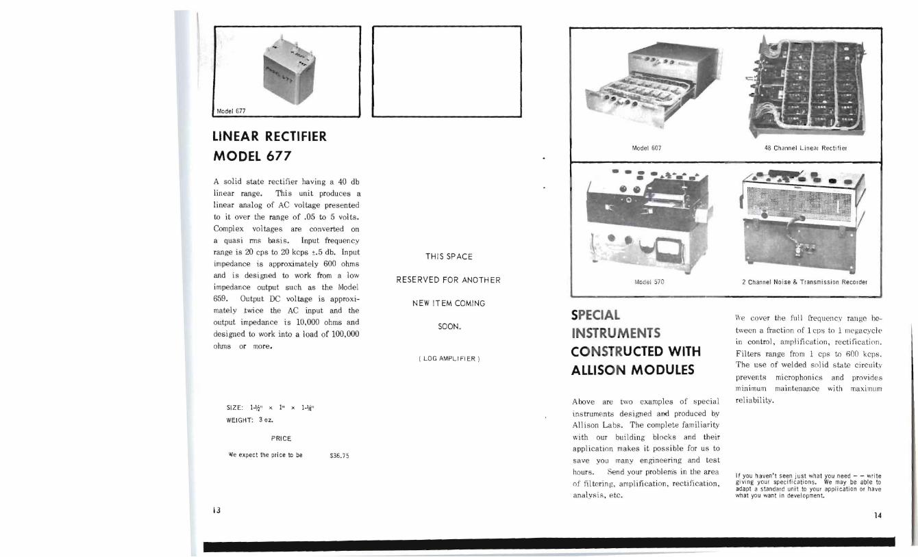
Model 677
LINEAR RECTIFIER
MODEL 677
A solid state rectifier having a 40 db
linear range This unit produces a
linear analog of AC voltage presented
to it over the range of 05 to 5 vol ts
Complex voltages are converted on
a quasi ems basis Input frequency
range is 20 cps to 20 kcps plusmn5 db Input
impedance is approximately 600 ohms
and is designed to work from a low
impedance output such as the Model
659 Output DC voltage is approxishy
mately twice the AC input and the
output impedance is 10000 ohms and
designed to work into a load of 100000
ohms or more
SIZE 1lf x 1 x JI~
WEIGHT 3 oz
PRICE
We expect the pri ce to be $3675
i3
48 Channel Linear Rectifier
THIS SPACE
RESERVED FOR ANOTHER
NEW ITEM COMING
SOON
( LOG AMPLI FI ER )
Model 607
Model 570 2 Channel Noise amp Transmission Recorder
SPECIAL INSTRUMENTS CONSTRUCTED WITH ALLISON MODULES
Above are two examples of special
instruments designed anlt produced by Allison Labs The complete familiarity
with our building blocks and their application makes it possible for us to
save you many engineering and test
hours Send your problems in the area
of filtering amplification rectification analysis etc
e cover the full frequency range beshy
tween a fraction of 1 cps to 1 megacycle in control amplification rectification
Filters range from 1 cps to GOO kcps The use of welded solid state circuity
prevents microphonics and provides minimum maintenance with maximum
reliability
If you havent seen just what you need - - write giving your specifications We may be able to adapt a standard unit to your application or have what you want in development
14
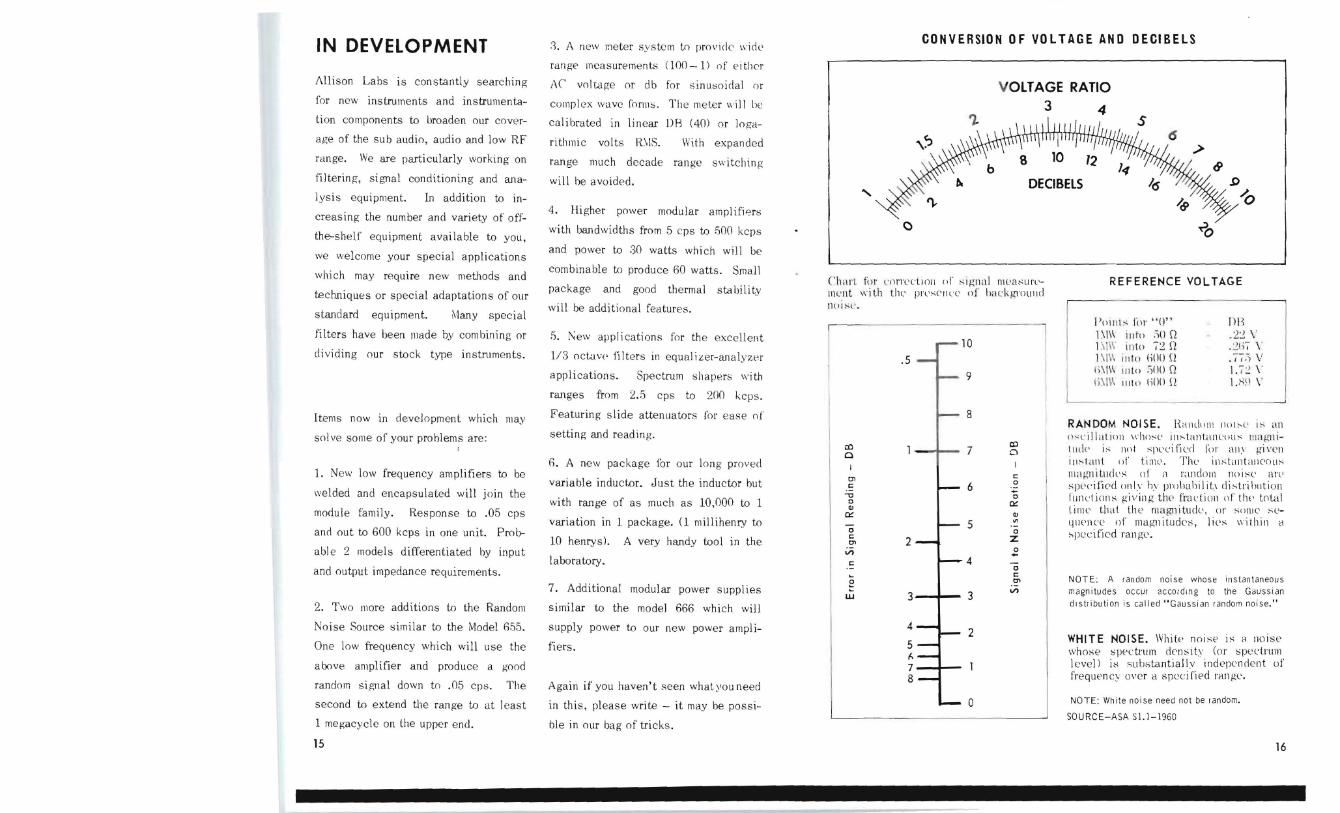
CONVERSION OF VOLTAGE AND DECIBELSIN DEVELOPMENT 8 A new meter sys tem to provide wide
range measurements (100 - 1) of e i ther illison Labs is constantly searching tC voltage or db for sinusoidal or VOLTAGE RATIO for new instruments and instrumentashy complex wave forms The meter will he 3 4 tion components to broaden our covershy calibrated in linear DR (40) or logashyage of the sub audio audio and low RF rithmic volts RIS With expanded range We are particularly working on range much decade range switching filtering signal conditioning and anashy will be avoided DECIBelS lysis equ ipment In addition to inshy
4 Higher power modular amplifi8rcreasing the number and variety of offshy cwith bandwidths from 5 cps to fiOO kcpsthe-shelf equ ipment available to you and power to 30 watts which will be we welcome your special applications combinable to produce 60 watts Smallwhich may require new methods and (h art ttl IDrrlllio ll of Igllal Illllt1SUI(middotpackage and good thermal stability lIlLnt Ii th the prlsCIllC of hcllkground techniques or special adaptations of our
no I S C will be additional features standard equipment Many special
filters have been made by combining or
dividing our stock type instruments
Items now in development which may
sol ve some of your problems are
1 New low frequency amplifiers to be
welded and encapsulated will join the
module family Response to 05 cps
and out to 600 kcps in one unit Prolr
abl e 2 models differentiated by input
and output impedance requirements
2 Two more additions to the Random
Noise Source similar to the Model 655
One low frequency which will use the
above ampl ifier and produce a good
random signal down to 05 cps The
second to extend the range to at least
1 megacycle on the upper end
fi few applications for the excellent
113 octavP filters in equal izer-analyzer
applications Spectrum shapers with
ranges from 25 cps to 200 kcps
Featuring sl ide attellliators for ease of
setting and reading
6 A new package for our long proved
variable inductor Just the inductor but
with range of as much as 10000 to 1
variation in 1 package (1 millihenry to
10 henrys) A very handy tool in the
laboratory
7 Additional modular power supplies
similar to the model 666 which will
supply power to our new power amplishy
fiers
Again if you havent seen whalyou need
in this please write - it may be possishy
ble in our bag of tricks
8
Q)0 7 0
I Q
cshy 06 -0 0 o ~ ~
5 Vl
o 0 z
Vgt c- 2
4 0
e ~ w 3-+-- 3
Vgt
4 2
5 f
7-+-shy8
o
~o
REFERENCE VOLTAGE
lllll 11s Itl[ 0 DI) 1 1 iII to )() n 22 1 1 inll 2 n 21 1 1 ill lo ()OO l I) V li I Ill to jIlO 11 I bull li I 1111 1l liOl1 12 I K~l
RANDOM NOISE HHllLi()1ll IHlI- l i all
L illd ion IIhosegt int alltltlllOUS lII ugn ishyIll d) is not plLi tiLr1 It)r am glvllI illlillll or t im( Thl ill tantallcous Illagllitlldcs of a randolll nOISl arC jll(ified onl hv jlmhahilit distriiliition runLlions giving thl fraction of til lotlt1i tilllc that tiH magniludl or sonic seshyljmncC of malrn itude lies ilhin a specified range
NOTE A landom noise whose instantaneous magnitudes OCCUI according to the Gaussian dlstlibution is cal led Gaussian random noise
WHITE NOISE Whitt noise is ltl no ise whose spectrum dcnslty (or spectrum IcveJl is substantially indepcndent of frequ ency over a specified rangl
NOTE White noise need not be random
SOURCE-ASA S11-1960
15 16
- --
212
237
265
297
334
I376
424
477 I
530
614
667
760
848
953
1060
l85
1320
1482
1693
1910
212 0
DECIBEL TO PERCENT
CONV ERSION CHART
DECI BELS PERCENT DECIBELS PERCENT
0 ~ 100 40 ~1990 80
70
605 --t=shy - 45
40
1O -~ 50
-l 20 15 55
15
20 i 60 L
25 6
65 06
----JL-shy 5 - 05
t= 4 t= 04
30 E 3
70-shy - pound 03
------ 2 -4---02 35 75
15 015
40---1-__ 80 01
EXAMPLE A Signal to Noise Ratio of 40 DB =10 Distortion
TABLE OF PREFERRED FILTER CENTER FREQUENCIES AND THEIR HIGH CUTOFF AND LOW CUTOFF FREQUENCIES PREFERRED CENTER FREshyQUENCIES ARE SPECIFIED IN ASA SPECIFICATION S 16-19amp0 FOR HIGHER OR LOWER FREQUENCIESMULTIPLY OR DIVIDE BY FACTORS OF 10
OCTAVES
1 3 OCTAVES
1 6_ OCTAVES
CENTER LOW HIGH FREQUENCY CUTOF F CUTOF F
7
6
5
4
3
CEN TER FREQUENCY
LOW CUTOFF
HIGH CUTOF F
315 224 45
63 45 90
125 90 180
250 180 355
500 355 710
1000 710 1400
2000 1400 2800
4000 2800 5600
8000 5600 11 200
16000 11200 22400
31500 22400 - - shy -_
45000 - -shy
CENTER LOW HIGH FREQUENCY CUTO FF CUTOFF
25 2236 28 06
315 2806 3549
40 3550 44 76
50 4476 56 12
63 5612 7098
80 7098 8943
100 8943 1117 9
125 I 179 14197
160 14197 17886
200 178 86 22358
250 22358 280 58
20
22 4
25
28
315
355
40
45
50
56
63
71
80
90
100
112
125
140
160
180
200
191
212
237
265
297
334
37 6
424
477
530
614
667
760
848
953
1060
1185
1320
1482
1693
1910
ASA STANDARDS MAY BE PROCURED FROM AMERICAN STANDARDS ASSOCIATIDN IN C 10 E 40th St
17 NEW YORK 16 NEW YORK 18
--
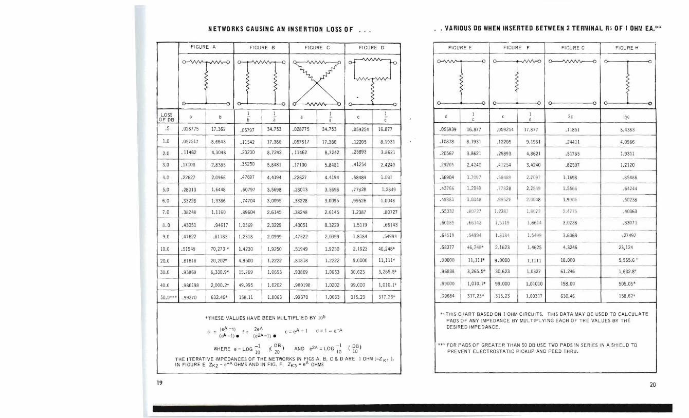
NETWORKS CAUSING AN INSERTION LOSS OF VARIOUS DB WHEN INSERTED BETWEEN 2 TERMINAL Rs OF I OHM EA~~
THIS CHART BASED ON 1 OHM CIRCUITS THIS DATA MAY BE USED TO CALCULATE
PADS OF ANY IMPEDANCE BY MULTIPLYING EACH OF THE VALUES BY THE
DESI RED IMPEDANCE
FOR PADS OF GREATER THAN 50 DB USE TWO PADS IN SERIES IN A SHIELD TO PREVENT ELECTROSTATIC PICKUP AND FEED THRU
19 20
UNITED STATES If you are In an area without present leps please contact the factory In wliting or call collect to 213-691-0115 01 697-7698 We will plovlde instruments fo trial in these areas just as our leps do in theil territories
Alaska Ava Inc PO Box 171 Ancholage Alaska BRoadway 2-6731
Ari zona Clark County Nevada
Williamsmiddot Associates 1608 E Ealll Phoenix Arizona 277-7858
Cal i forni a (northern) Dynamic Associates 1011 D Industli al Way BUllingame California 344-2521
Col iforni a (Southern) Phil l ip Diamond Ente lprises 13615 Vi ctolY Bl vd
Van Nuys Callforn ld
873-6822
Illinois Indiana Iowa Kentucky an d Eastern Wisconsin
R Edward Stemm 5681 WLake sHeet Chicago Illinoi s 60644 379-2700 (312)
Colorado Nebraska Wyoming and
Easte rn Montana
Wi ll iams bull Associates 4971 Jackson Street Denvel 16 Cololado 388middot4391
Hawaii
AI Mi cheli 9 4~ McCu ll y Street Hono lul u Hawaii 993 - 149
Massachusetts Rhode Island Maine Vermont and New Hampshire Burlingame ASSOCiates 7 Wellington St leet Waltham 54 Massachusetts TWrnbrook 4-1955
ALLISON AUTHORIZED REPRESENTATIVES
Michigan The Tiby Company 8701 Fenkell Avenue Detlolt 38 Michi gan TExas 4-9211
Minnesota North amp South Dakota and western Wisconsin Pat Lind Electronic s Company 9781 Western Avenue Circle Pines Minnesota 781-6568
New Mexica and EI Paso County Texas
Williams - Associates 3221 Silver Avenue S E Albuquerque New Mexico 255-9632
New York (NYC area) New Jersey and Connecti cut Burlingame Associates 510 So Fulton Avenue Mt Vernon New York MOunt Vernon 4-7530
New York (northern area) Burlingame Associates 106 Pickard Building East Molloy Road Syracuse New York 454-2408
Ohio western Pennsylvania The Tiby Company 2245 Warren sville Centel Road Cleve l and 18 Ohio ERleview 1-5335
Ohio The Ti by Company 1954 NOlth Main St leet Dayton S Ohio CRestview 7-3822
Oregon Ava Inc 2035 SW 58th Avenue Portland 1 Oregon CApital 2-7337
Pennsylvania (Philadelp hia area) Burlingame Associates 222 Long Lane Upper Darby Pennsylvania JAckson 8-G080
Utah
Williams - Associates 362 Pierpont Avenue Salt Lake Crty 1 Utah 328-3101
Washington Idaho and western Montana Arva Inc 1320 Prospect Street Seattle 9 WaShington MAin 2-0177
Was hington Alva Inc E 127 Augusta Avenue Spokane 10 Washington FA 5-2557
Wa hington DC Ma ryland Delaware and narthern Virg in ia
BlJrllngame Associates 8218 Wisconsin Avenue Washrnampton 14 DC Oliver 4-6400
FOREIGN REPRESENTATIVES
Austral ia Ronald J T Payne Pty Ltd 385-389 Bridge Rd Richmond Victoria Australia
Canada EJ ectrodesr gn 9124 51 Lawrence Blvd Montreal 11 Canada DUpont 9-5914
Electrodesi go 491 L awr ence A~e W Toronlo OntariO RU 7--099)
EJectrodesr go 166 Charlotte St Ottawa OntariO CEntral 4-9366
AUTHORIZED ALLISON REPRESENT ATIVES
Canada Novo Scoti a New Eorunswi ck Prince Edward Island amp Newfoundland EJectrodesrgnL J Payzant Pres P O Box 862 Halifax Nova Scotia
Conada Vancouver Arvalnl 1624 W lrd Avenue Vancouver 9 B C REgent 6-li377
England Livingston Labor atOll es Ltd 31 Camden Road London N W I Enel and
France B Freudenbelg Inl 50 Rockefeller Plaza New York 20 New Yorl(
Ind ia K Lal Bhakrl p O Bolt 481 New Deihl I India
Italy Dott Ing Marlo Vlanello Via L Anel l l 13 Milano Italy
DotL Ing MallO Vjanello Via S Croce in Gerusalemme 97 Rome Italy
Japan Rikei T rading Co Ltd Kozato Kalkan Bldg 12 2-Chome Shlba Tamura-Cho Mlnato-Ku Tokyo Japan
The Nethe rlands Luxembourgr and Belgium Hawinco n Y Renssenstr aal 13 Arnhem Holland
Narway Brlti sb Imports AS Major stuvei en 3S Oslo NOlway
Sweden John C La gerclilntz Vartavagen 57 Smckholm Sweden
Switzerl and Germany amp Austri a Elektronllo Postcheck-KTO 1X15575 Schann FL Swrtzerland
Dmnl Ray GmllH Nymphenburger SlIasse 164 Munche 19 Germ any
Austronlk Gmbl1 Vienna Au sul
NETWORKS CAUSING AN INSERTION LOSS OF VARIOUS DB WHEN INSERTED BETWEEN 2 TERMINAL Rs OF I OHM EA
_ FIGURE A FIGURE B FIGURE C FIGURE 0 FIGURE E FIGURE F FIGURE G FIGURE H
THESE VALUES HAVE BEEN MUL TIPLIED BY 105 THIS CHART BASED ON I OHM CIRCUITS THIS DATA MAY BE USED TO CALCULATE PADS OF ANY IMPECANCE BY MULTIPLYING EACH OF THE VALUES BY THE
(eA -1) _ 2e A c =e A + I d = I - e-A DESIRED IMPEDANCE
a = ~ fshy (e 2A -I) bull
-1 (~) AND e2A = LOG -I ( Qsect) FOR PADS OF GREATER THAN 50 DB USE TWO PADS IN SERIES IN A SHIELD TO WHERE e =LOG 10 20 10 10 PREVENT ELECTROSTATIC PICKUP AND FEED THRU
THE ITERATIVE IMPEDANCES OF THE NETWORKS IN FIGS A B C amp 0 ARE 1 OHM (=ZK l IN FIGURE E ZK2 =e-A OHMS AND IN FIG F ZK3 e A OHMS
-
19 20
INSTRUMENTS OF QUALITY
Continuously Variable Passive Filters
Spectrum Equalizers
Spectrum Analyzers
Modular Amplifiers
Random Noise Sources
Automatic Inspection Units
Multiple Oscillators
Instru mentation Modules
Custo m Instru mentation
Pr()fea JepelJaabJe in years of Jertice
Allison Laboratories Inc PO BOX 515 LA HABRA CALIFORNIA 90631
Model 201 series 2
VARIABLE FILTERS wide dynamic range
no internal noise
flat pass bands
steep co ntinuou s attenuation
negligible ringing effect
SERlES 2 The Model 2 Series are variable passive network filters with indepe ndent hi gh cutoff and low cutoff se c tions Each section has a ran ge swi tch tha t changes the cutoff in OCt I V(gt te ps lUI a vem ilr dial that tlUHS liver a range of ()J IP
octave The a ttenu ati on ratl is m dh per octave an d lilP) nray he (scadcd for increased a tten ua tion Two fi llkrs give 60-70 db per I)c ta vP Thegt mo()I h pass band is fl a l i1 db over olO of the pass band It Ina) be tuned to a handshy
width as narrow as 1 middot DClavC The
maximum in put voltage is 2 vol is The input and output impedance is 600 oh ms
Size 7middot ll hi gh 7J i deep 17J 1 w ide
Rack model is mounted on a 7 panel with 6 1 behind panel
Rack mount is the same price and shipping weight for ]1 models
Add 150 of the standard unit price for hermeti cally sealed capacitor~
T Y Dlcal C u -v e r--rr-shy v [ lAiJ I 1
MODEL 20 1 The new Model 201 extends into the sub-audio range while retaining all of the desirable characteristics of the 2 se rie s such as excellent transient hanshydling capability ability to handle small signal parameters and no active eleshyments The low noise low distortion and good transi e nt handling capacities of this filter make it excellent for studi es of low level transient phenomena s uch as encountered in heart studies geophys ical work th emocoupleR and low frtmiddotqu ency vi brations Wi th high cutshyoff onl y the filter will pals DC to the cutoff frequen c
chart reClding into cps
i th e
provided multipli( r
on the dial
pane l direc
for tl y
Low cutoff sect io n bullbullbull 1 to J28 cps High cu to ff secti on 2 to 256 cps
Size 7middot IJ high 17middotl i wide 7middot1 i deep Rackmoun t 7 hi gh 19 Wide 6middot l i deep
201 Sh WRt 35 S725 201 R Rack Moullt Sh Wgt 35u $725
Hermetic Capacit ors Not Available
l lllli l l l Y li I I I++J-l 0
I -I TI I I 91 -r+-W--++-r--~
- 0
0
2
Model 420 Model 460 Typical Filter
Designed as an inexpensive general purpose filter for laboratory and proshyduction use the 420 is very simple to operate and is direct reading with a single knob control for each section covering a range from 20 to 20000 cps A selector is provided for switchshying the filter out low cutoff only high cutoff only or band pass mode of operation There is 20 db or more attenuation per octave for the first octave wi th attenuation outside the pass band exceeding 25 db at all frequencies beyond an octave away from cutoff frequency Minimum bandshywidth - approximately h octave Maxishymum input-2 volts Impedance-600 ohms
Portable - excluding knobs and handle (Shown) 17 long 5~3 deep 8 high
Available also in rack mount case with 7 x 19
panel and 5middot~~ behind the panel
TYPICAL CURVES
10
D I o ~ l O
~ 0 o ~ 0
60
----shy
-
1 ~ II
JJ
V 70 1 1 tI l I(
FPfOU EN C1
Curve 111-1 Model 420
6 e 10K
Curve 112-2 Model 420 Filters in Series
420 Sh Wgt 2411 $385 420R Rack Mount Sh Wgt 3011 $385
3
This filter also features the single knob tuning The rejection band may be moved continuously over the range of 20 to 20000 cps The reject band is slightly less than 1 octave wide at the -3 db points Attenuation at the bottom of the reject band varies as shown in the curves below It can be used to eliminate single components as intershyfering hum the resonant peak of an accelerometer a fundamental or conshystant tone to facilitate analyses of the remaining frequency spectrum Filters used in series eliminate ditional frequencies
460 adshy
Impedance bull 600 ohms Reject band Less than 1 octave wi de
Maximum input 2 volts
Portabl e 17 long 5middot deep 8 high
Available also in rack mount (Shown with 7 x 19 x 5middotyenI)
TYPICAL CURVES
0
3 ~7 I
sect) I
10 50 100 OO 1000 SODa 0000 FR tOUfNC (
460 Sh Wgt 2411 S395 460R Rack Mount Sh WgL 3011 $395
IMPEDANCE MATCHING
TRANSFORMERS These units are used for applications where it is inconvenient to match impedances of 600 ohms The AL-483 Input Transformer is an autotransformer designed to work from approximately 10000 ohms to the 600 ohm circuit of the filter The AL-484 Output Transshyformer is designed til malch the 600 ohms impedance of the fll ter into the grid of Il vacuum tulx~ or a VTVM The output transformer has an impedance ratio of 600 to 45000 ohms A tershyminating resistor transformer to the filter
pis hui lt roperly
into tenni
the nate
Each transformer is encased ih a mushymetal case and a grounded steel case
In the event that high impedance inputs are required in frequencies above or below the above limits refer to the Model 659 amplifier These units have input impedance of 40000 ohms and match the filter using a 600 ohm series resistor The frequency coverage can be extended in this manner from 10 cps to 500 kcps
AL-483 Input Autotrans 10000600 ohms $35
AL-484 Output Trans 600 ohmsGri d 535
FIXED 13 OCTAVE
FILTERS Fixed 113 octave filters having exshycellent and uniform response Each model consists of 1 decade of 10 filters case complete with power supply
These are passive networks using solid state isolation and amplification
Standard filters are on iSA preferred (()Ilter frltqllencies Special fllters may be ordered to other frequencies and down to 5 bandwidth Individual filter s are also available cased or un ca sed as desired
TYPICAL CURVE ALL FIL TERS
5 6 J 3 rc
Il
O
40
so
MODEL FREQUENCY PRICE
240 25 - 20 $2850
241 25 - 200 1500
242 250 - 2000 900
243 2500 - 20000 850
244 25000 - 200000 850
Individual filters by quotation
See also 13 octave analyzer page 8
Model 650
RANDOM NOISE SOURCES MODEL 650 A superior random noise source for general use Using the Model 655 Module as a sou rce it provides refershyences and controls Filters are also provided for equal energy per octave (Pink) noise 12 db octave roll off above 1000 cps and a 100 to 300 cps narrow band The unit is non microshyphonic and hnf a maximum output of 15 vrlllS in the equal energy per cycle setting This is widely used as a signal source for shake tables acollstic testing etc Available also in rackshymount case on a 3-Ih x 19 panel x 6-112 Standard model uses the Model 655 ~ource at the right Special mode may be made wi th the ~lode l 685 at an increaed price
Model 650R
Po rtable
Portab le
Rack Mount
Rack Moun t
$295
310
310
325
PRICES Battery
AC
Battery
AC
t 1
III Model 655
MODEL 655 An extremelv useful Iloise module for many applications Commonlv int e rshynal lv mounted for tes t and calibra tion signal s in variou in struments Reshyquires on ly 225 VDC to produce randllm noise havin g good Gauss ian distli butioll of amp I i tudes and ulli form spectral density A s ili con diode furnishe~ the signal sou rce fu r a german ium transisshytorized ampli fler Frequency rls[lon l is 5clls to 30kcps and tvpicnll pr(~ duces 2 volts rms into 10K ohm Id Templtrature stabilih is applOximatc ly ~3db over 0deg to 50degc
Price - lo 0 ~75 ()O lICh
MODEL 685 Samlt size and power rcquirellwnt1 as the 055 but is all si licon constnlClioll Outstanding for temperature stahili ty wi thin 2db from 0deg to ti(f c Price - 1 to 9 $R(lOU each
MODEL 681 Agaiu same size and construction as llodcl 655 except frequency response from lOcps to 1 mcps Lower voltage out sHOOO Clt1ch
MODEL 657 High temperaturl device having all silicon adive (dcll-nts plus tnntnlum capac itors PertcJnname 5cp to J50kc ps over tempe rature range of -20degC to +85degC s10000 elt1ch
Write for quantity pricls and specifishycations on all models
OCTAVE BAND EQUALIZERS AND SPECTRUM SHAPERS MODELS 318middot19middot48middot49 These newly redes igned instruments present a series of octave band filshyters sets for man uses They may contain 8 01 9 octave bandf on the new preferred frequency centers starting at 315cps and LIP to Jok eps All fllte rs are fed ill parall e l on the inpu t and have individual new s lide type atshytenuator~ to control the Ievel in each band The Ytode s 3 l B and 3 J9 a rc complele filtpls sets for USE with any si gnal source
Models 348 and 349 are simi lar to the above two model s but in addition have a random noise source plus input and output ampli fiers This provides a complete shaped spectrum si gnal for driving shake tables high level acoustic test facilities and many other appli cations
Typical Filter Curves
lJ I J A iri)( 1-- i
l H IJ I t~ il I I M
1 _ A li I
Size lOW x 19 Rack Pane l
14 behind the panel
Model Desc ript ion Pri ce
318A 8 Band Fi Iter $1350 319A 9 Band Fi Iter 1500
34BA 8 Bands wi noise generator 1650 349A 9 Bands wi noise generator 1850
bull bull bull bull bull bull I -I -
Model 322
MODEL 322
This new intrument IS a continuation
of lhe 300 series at left The ue o f
new slide atten uators pillS excellen t
1 1 octave filters give gItater definishy
tion to s haped spEctrums oe r the
cente r frequencies from 20 cps to
250 kep ma ximul1l of 22 fi Iters may
1)( included ill this range such a 20cps
lo 2500cp The complete 13 oetac
spries are in decades sta rlin g wilh 25
315 40 50 03 80 100 125 HiO and
200cl1s Centers above and below may
he obtained as a factor o f 10 100 or
1000 above or below these frequencies
A random noise source is included in
this instrument plus its associated
power supplies amplifiers and ci rcushy
itry This makes a complete signal
source for s haped spectrums For
typical filter c urves see page 4
SIZE 121iXI9 rack panel 19 behind the panel
Pr ices start at $385000
5 6
1
Model 358-359
MODELS 358-359 Thce arC simultaneous octave band analyzers having either 8 or g octave hand filters The filters are fed in parallcl and each channel is provided with a me ter circuit on the output ThE meters read in decibels the energy in each octave of the spectrum Specishyally dampld meter circuit have good reponsc to complex sign a l such as mndom noise The instantaneo us reado ut rna be reco rded from individual uutput or photographed Octave hculCjs are on pre ferred ficquen lY centClij oer th( rallge of 315cps to 16kcJlb II V
8 vr g bands muv h se l f~c ted
TYPICAL C URVES
~
Si ze 19 wi de 101j hi gh 15 deep
PRICES Model 358R $2635 Model 359R S2990 ~
Model 533
MICROPHONE ACCESSORY MODEL 533
Modelmiddot532
OCTAVE BAND ANALYZER MODEL 532 The Allison 5a2 OctavE Band Analyzer is a small lightweight spectrum ~lllttlshyyzer that is exceedi ngl) easy to op~rshyate The intl1lmcnt consi sts of il
complete ana lyz ing c ircliit including attenuator and metlL I ed wi th a sound level meter it wi ll mcasun signal compOIlPnts in octan bands Sri db helow the overal l ignai Iend l -ed with the ~l()dei 5n shol] at the right it ill mCaurC and lIlahzlt lt)lI nd from (i5 tu n(l dh soulld PI( sure le vel The 532 is also suitable for lISl with rCshycordcri and microphonC preampl ilkr and si milar equipment It is useful for the octave hand amdvsis of environshymental noic~ cOl1lplex audio signal ploductiuLl acceptance levels
line and
testing speech
noise level interference
SIZE 6middot x 6middotJA x 5 WEIGHT 711 PRICE $42500
The Model 533 Accessory Kit consists of a very stable and reliable dynamic microphone tripod cable and input transformer This arrangement permits the Model 532 to be used as a sound level meter for sound pressure levels above 65 db The kit has a 25 foot cable fumished and a 100 foot exten sion is available middotThe combination 532 and 533 will make industrial sound survey curate
MODEL 540 The Allison Model 540 is a new and exciting instrument for 113 octave spectrum analysi s wi th many applishy
cations The extreme flexi bi Ii ty of of fil ter selection over a range of 25 cps to 200 kcps makes it suitable for standa rd or special purpose tests A repetitive 1 second display of the
spectrum allows high speed te ~ ting of product or imnllJiate ( aluation of design chan(s CUld adj ustments
The input signal is fed to a hank of
113 octave passive network bandpass filters The individual filter output is rectified and stored in a capacitor Each capacitor is sampled consecutive ly 10 times per second by a motor driven commutator switch The switch output
is amplified logarithmically and the
signal is displayed on the calibrated oscilloscope screen shown above Simultaneously calibration signals are
displayed to show instrument accuracy
during the test The filters are Conshytinuously open and all signals are reshy
ceived integrated and stored for display
The standard Model 540 shown above covers the range of 25 cps to 20000
cps Filters are Allison standard Models 241 242 and 243 (Page 4)
The newness of this instrument prevents a previous background of applications however the basic versatility of the unit shows that uses are limited mainly by the fmquency range voltage range and the imagination of the user It will display the analysis of any repetitive
simple or complex waveform or pulses ithin the above limitations Many accessories to the standard device can adapt it to various test situations such as a microphone for acoustic input an accelerometer for vibration pickup etc Revisions to the standard model can be made to adapt it to a variety of situations such as narrow band filters or a comshybination of standard 113 and 116 octave
filters to increase resolution of certain areas linear rectification only for expanded scale close tolerance measureshyments multiple speed scanning motors for recording requ irements special outputs per channel to operate go - no
go apparatus Cal ibration references permit readout in voltage decibels re 1 millivolt or sound pressure level
SIZE WEIGHT
22 wide x 30 high x ]8300
deep
PRICE $725000
8 7
Model 541 Model 60lA Model 660
M ULTIPLE FREQUENCY OSCILLATOR MODEL 541
The orill )4] provides a long fe lt need
for ltl si mullaneous multiplE frequen c~
tc~t si Ipoundl lill ar iations of packagilJgshy
call pr () v id(~ fmll ] L to )() frequ c ncins in
in tillt rg frolll 2 cp~ 10 200 kq)
Individual amplitude controls all nws
sllUping of the spectrum as dei red
S~ i tehes and meters may be added
to give thE individual or overall refershy
ence level
Primaril y deil-rn ed as a known conshy
trollable test signal for the Model 540
it is adaptabl e by changing frequencies
or number of oscil la tors Other uses
include shaker table drive signal proshy
(Tamable oscillator etc The 541
features all so lid s tate circuitry and
sel f contained power supply Output
is 1 5 Vrms per freguency and approxi shy
mately 8 Vrms for 30 oscillators
WEIGHT 20
SIZE 3--Ji x 19 x 14 deep
PRICE (30 Oscill ators) $95000
9
AUTOMATIC INSPECTION UNIT MODEL 601A 1111 1)01 i~ all illlpr()middotcmiddotd solid stille
in s tMlIlwnt for rapid automatic in plctinn
of ollnd or vihration in iUI ~ produ c t It
cOflil-qfan (Jptional tfH lI dl rclmiddotr amp lishy
fi er variahl flll cgtr attl lIU utor ml( r
and relay circui t to if(l1a l acccptanc(
or rej cction of til( produ ct unde r le t
The high cutoff low cutoff or band
pass filler s cover the ran ge of fiO
cps to 20 kcps When set to pa ss
obj ectional frequencies it will measure
level and operate go no go indishy
cators or separating devices Thi s
uni t is used extensively on gears
bearings and similar products The
instruments may be made with 2 chanshy
nels of filter and indicating circuits
SIZE 10~12 x 22 x 6-
WEI GHT (Single channel) 33u
PRICE Wllt e gIvIng your lequ ltements tOI
quotatron
INSTRUMENTATlON MODULES MODEL 660
Welded and encapsulated modules are easily adapted to your ci rcuitry whether breadboard or production The Model 660 is a very low noise flexible preshyamplifier having adj ustable gain and bandwidth Using only 1 MA of 135 to 225 VDC it saves space and power The feedback loop is brought out to pins on the top of the module This allows customer selection of feedback value for gain and resulti ng bandwidth Turned c ircuits may also be inserted for selective amplification ~lolded
in 6-32 inserts simplify mounting Transistors are readily serviced since sockets are also molded in
GAI N AT 1 KC PS 20 to 40 db
GA IN STABILITY plusmn5 db Odegc to 50degc
INPUT IMPEDANCE 40000 ohms
AVERAGE CURRENT lMA
SIGN AL TO NOISE RATIO
85 db
FREQUENCY RESPONSE 20db 10 cp s to 1 mcs 40db 10 cps to 50 kc
1 middot 9 $3300
See pages 12 amp 13 for more new modules to extend power and signal conditioning capabili ties of these handy buildshying blocks
Model 659
MODEL 659 (class B)
Another welded and e ncapsulated modu le designed to be used in filter driver applications An output of 6 volts into 600 ohms with an input impedance of 40000 ohms makes i t sui table for many other ci rcuits Again as in the Model 660 it has an open feedback loop for variation of gain and bandwidth Used in conjunction with the Model 660 and 671 meter system it fonns a tran s istorized voltshymeter with sens itivity to 001 volts rms
GAIN AT 1 KCPS 30 to 40 db GAIN STABI L ITY 5 db 0 to 50degc
INPUT IMPEDANCE 40000 ohms AVERAGE CURRENT 2 to 17 MA
FREQUENCY RESPONSE 30db iO cps to 400 kcps 40db 10 cps to 100 kcps
PRICE 1-9 S4000
MODEL 658 (class A) For multiple channel use from common power source use Model 658 Same performance on constant 12 MA
VARIABLE GAIN KIT MODEL 661 Provides self mounted variable conshy
trol as well as shieldin g when used in Illu ltiples for high gain appli cu tions
PRICE $850
10
Model 666
POWER SUPPLY
MODEL 666
The Allison Model 666 regulated power
supply is a solid state dual module
device Designed primarily for the
operation of various Allison modules it
may be used for many other insbushy
mentation applications
The two unit design offers a variation
of mounting arrangements for minimum
space and convenience It also allows
variation on the bansformer when someshy
what larger or smaller power requireshy
ments occur
The 606 will produce 100 milliamps of
well regul ated 25 vol ts for operation of
as many as 6 Model 6598 Model 658 10
Model 660 or combinations of these
SPECIFICATIONS
INPUT POWER 110-130 S0-60 cps S VA
OUTPUT VOLTAGE 24 VDC 2V
CURRENT OUTPUT 100 Milliamps DC Max
OUTPUT RIPPLE 3 Millivolts
SIZE Tlans Rect - Reg
1-1316 x 1middot1 2 x 2-12 1 x 2middot18 x 2middot18
WEIGHT 8 oz
P RI CE SS2 SO
-shy
Model 671
METER SYSTEM
MODEL 671 This model offers an extremely simple I method of monitoring AC voltages or
decibels in systems or instrumentation
The full wave bridge rectifier is welded
and encapsulated for easy mounting
either adj acent or remotely from the
meter Used with the Models 660 and
658 it forms a transistorized voltmeter
with 001 volts sensitivity and freshy
quency response from 10 cps to 50 kcps
Meters are available wi th ei ther or both
AC volts and decibels The meter used
is a Z-W standard 3 screw mounting
type Indication is quasi rms An
extra terminal is provided for ei ther
slow or fast meter damping for measureshy
ment of constant or fluctuating vol tages
SPECIFICATIONS
SENSITIVITY 0 db = 66 volts
+10 db = 21 volts
FREQUENCY RESPONSE -5 db at 20 cps amp
600 kcps
INPUT IMPEDANCE 19 k ohms
PRICE S4500 (Standald scale)
PRELIMINARY ANNOUNCEMENT OF NEW PRODUCTS
Model 683( class fJ
NEW ALL SILICON 60 MILLIWATT AMPLIFIER MODEL 683(classA) The use of newly deve loped PNP silicon transistors in push pull circushyitry makes this new module possible Compact and highly reliable it has excellent specifications for noise variable gain distortion stability and other characteristics This operates full Class A with a constant CUITen t of 12 mi lliamps at 225VDC Frequency response of -ldb at lOcps and 240kcps Output (j volts into (j00 ohms
MODEL 684(class B) The Class B counterpart of the above unit for use where minimum current usage is a requirement
Most all spec ifications the same exshycept average current is 24 milliamps with no signal
$S500
10 24 48S0
2S 49 4200
SO 100 3850
Model 195
CONTINUOUSLY VARIABLE INDUCTOR MODEL 195 A brand new aid to designers is a con tinuousl v varia ble inductor with a range of HiooO to 1 (1 millihen ry to 10 henri es) Compact and simple in operation it has the full range in 8 steps in a 1 -32 32 -10 series
The inductor has many appl ica tions including equalizers filters oscilshylators adjustable delay networks and adjustable phase shift networks plus many others
Tuning is accomplished by the patented All ison variable inductor which has proved itself in many years of fin e performance in our continuously varishyable filters
Write for specifications and curves of induc tance Q frequen cy response and other characteristics
Size 512 W x 812 H x 5 D
Price $95UO each
11 12
Model 677
LINEAR RECTIFIER
MODEL 677
A solid state rectifier having a 40 db
linear range This unit produces a
linear analog of AC voltage presented
to it over the range of 05 to 5 vol ts
Complex voltages are converted on
a quasi ems basis Input frequency
range is 20 cps to 20 kcps plusmn5 db Input
impedance is approximately 600 ohms
and is designed to work from a low
impedance output such as the Model
659 Output DC voltage is approxishy
mately twice the AC input and the
output impedance is 10000 ohms and
designed to work into a load of 100000
ohms or more
SIZE 1lf x 1 x JI~
WEIGHT 3 oz
PRICE
We expect the pri ce to be $3675
i3
48 Channel Linear Rectifier
THIS SPACE
RESERVED FOR ANOTHER
NEW ITEM COMING
SOON
( LOG AMPLI FI ER )
Model 607
Model 570 2 Channel Noise amp Transmission Recorder
SPECIAL INSTRUMENTS CONSTRUCTED WITH ALLISON MODULES
Above are two examples of special
instruments designed anlt produced by Allison Labs The complete familiarity
with our building blocks and their application makes it possible for us to
save you many engineering and test
hours Send your problems in the area
of filtering amplification rectification analysis etc
e cover the full frequency range beshy
tween a fraction of 1 cps to 1 megacycle in control amplification rectification
Filters range from 1 cps to GOO kcps The use of welded solid state circuity
prevents microphonics and provides minimum maintenance with maximum
reliability
If you havent seen just what you need - - write giving your specifications We may be able to adapt a standard unit to your application or have what you want in development
14
CONVERSION OF VOLTAGE AND DECIBELSIN DEVELOPMENT 8 A new meter sys tem to provide wide
range measurements (100 - 1) of e i ther illison Labs is constantly searching tC voltage or db for sinusoidal or VOLTAGE RATIO for new instruments and instrumentashy complex wave forms The meter will he 3 4 tion components to broaden our covershy calibrated in linear DR (40) or logashyage of the sub audio audio and low RF rithmic volts RIS With expanded range We are particularly working on range much decade range switching filtering signal conditioning and anashy will be avoided DECIBelS lysis equ ipment In addition to inshy
4 Higher power modular amplifi8rcreasing the number and variety of offshy cwith bandwidths from 5 cps to fiOO kcpsthe-shelf equ ipment available to you and power to 30 watts which will be we welcome your special applications combinable to produce 60 watts Smallwhich may require new methods and (h art ttl IDrrlllio ll of Igllal Illllt1SUI(middotpackage and good thermal stability lIlLnt Ii th the prlsCIllC of hcllkground techniques or special adaptations of our
no I S C will be additional features standard equipment Many special
filters have been made by combining or
dividing our stock type instruments
Items now in development which may
sol ve some of your problems are
1 New low frequency amplifiers to be
welded and encapsulated will join the
module family Response to 05 cps
and out to 600 kcps in one unit Prolr
abl e 2 models differentiated by input
and output impedance requirements
2 Two more additions to the Random
Noise Source similar to the Model 655
One low frequency which will use the
above ampl ifier and produce a good
random signal down to 05 cps The
second to extend the range to at least
1 megacycle on the upper end
fi few applications for the excellent
113 octavP filters in equal izer-analyzer
applications Spectrum shapers with
ranges from 25 cps to 200 kcps
Featuring sl ide attellliators for ease of
setting and reading
6 A new package for our long proved
variable inductor Just the inductor but
with range of as much as 10000 to 1
variation in 1 package (1 millihenry to
10 henrys) A very handy tool in the
laboratory
7 Additional modular power supplies
similar to the model 666 which will
supply power to our new power amplishy
fiers
Again if you havent seen whalyou need
in this please write - it may be possishy
ble in our bag of tricks
8
Q)0 7 0
I Q
cshy 06 -0 0 o ~ ~
5 Vl
o 0 z
Vgt c- 2
4 0
e ~ w 3-+-- 3
Vgt
4 2
5 f
7-+-shy8
o
~o
REFERENCE VOLTAGE
lllll 11s Itl[ 0 DI) 1 1 iII to )() n 22 1 1 inll 2 n 21 1 1 ill lo ()OO l I) V li I Ill to jIlO 11 I bull li I 1111 1l liOl1 12 I K~l
RANDOM NOISE HHllLi()1ll IHlI- l i all
L illd ion IIhosegt int alltltlllOUS lII ugn ishyIll d) is not plLi tiLr1 It)r am glvllI illlillll or t im( Thl ill tantallcous Illagllitlldcs of a randolll nOISl arC jll(ified onl hv jlmhahilit distriiliition runLlions giving thl fraction of til lotlt1i tilllc that tiH magniludl or sonic seshyljmncC of malrn itude lies ilhin a specified range
NOTE A landom noise whose instantaneous magnitudes OCCUI according to the Gaussian dlstlibution is cal led Gaussian random noise
WHITE NOISE Whitt noise is ltl no ise whose spectrum dcnslty (or spectrum IcveJl is substantially indepcndent of frequ ency over a specified rangl
NOTE White noise need not be random
SOURCE-ASA S11-1960
15 16
- --
212
237
265
297
334
I376
424
477 I
530
614
667
760
848
953
1060
l85
1320
1482
1693
1910
212 0
DECIBEL TO PERCENT
CONV ERSION CHART
DECI BELS PERCENT DECIBELS PERCENT
0 ~ 100 40 ~1990 80
70
605 --t=shy - 45
40
1O -~ 50
-l 20 15 55
15
20 i 60 L
25 6
65 06
----JL-shy 5 - 05
t= 4 t= 04
30 E 3
70-shy - pound 03
------ 2 -4---02 35 75
15 015
40---1-__ 80 01
EXAMPLE A Signal to Noise Ratio of 40 DB =10 Distortion
TABLE OF PREFERRED FILTER CENTER FREQUENCIES AND THEIR HIGH CUTOFF AND LOW CUTOFF FREQUENCIES PREFERRED CENTER FREshyQUENCIES ARE SPECIFIED IN ASA SPECIFICATION S 16-19amp0 FOR HIGHER OR LOWER FREQUENCIESMULTIPLY OR DIVIDE BY FACTORS OF 10
OCTAVES
1 3 OCTAVES
1 6_ OCTAVES
CENTER LOW HIGH FREQUENCY CUTOF F CUTOF F
7
6
5
4
3
CEN TER FREQUENCY
LOW CUTOFF
HIGH CUTOF F
315 224 45
63 45 90
125 90 180
250 180 355
500 355 710
1000 710 1400
2000 1400 2800
4000 2800 5600
8000 5600 11 200
16000 11200 22400
31500 22400 - - shy -_
45000 - -shy
CENTER LOW HIGH FREQUENCY CUTO FF CUTOFF
25 2236 28 06
315 2806 3549
40 3550 44 76
50 4476 56 12
63 5612 7098
80 7098 8943
100 8943 1117 9
125 I 179 14197
160 14197 17886
200 178 86 22358
250 22358 280 58
20
22 4
25
28
315
355
40
45
50
56
63
71
80
90
100
112
125
140
160
180
200
191
212
237
265
297
334
37 6
424
477
530
614
667
760
848
953
1060
1185
1320
1482
1693
1910
ASA STANDARDS MAY BE PROCURED FROM AMERICAN STANDARDS ASSOCIATIDN IN C 10 E 40th St
17 NEW YORK 16 NEW YORK 18
--
NETWORKS CAUSING AN INSERTION LOSS OF VARIOUS DB WHEN INSERTED BETWEEN 2 TERMINAL Rs OF I OHM EA~~
THIS CHART BASED ON 1 OHM CIRCUITS THIS DATA MAY BE USED TO CALCULATE
PADS OF ANY IMPEDANCE BY MULTIPLYING EACH OF THE VALUES BY THE
DESI RED IMPEDANCE
FOR PADS OF GREATER THAN 50 DB USE TWO PADS IN SERIES IN A SHIELD TO PREVENT ELECTROSTATIC PICKUP AND FEED THRU
19 20
UNITED STATES If you are In an area without present leps please contact the factory In wliting or call collect to 213-691-0115 01 697-7698 We will plovlde instruments fo trial in these areas just as our leps do in theil territories
Alaska Ava Inc PO Box 171 Ancholage Alaska BRoadway 2-6731
Ari zona Clark County Nevada
Williamsmiddot Associates 1608 E Ealll Phoenix Arizona 277-7858
Cal i forni a (northern) Dynamic Associates 1011 D Industli al Way BUllingame California 344-2521
Col iforni a (Southern) Phil l ip Diamond Ente lprises 13615 Vi ctolY Bl vd
Van Nuys Callforn ld
873-6822
Illinois Indiana Iowa Kentucky an d Eastern Wisconsin
R Edward Stemm 5681 WLake sHeet Chicago Illinoi s 60644 379-2700 (312)
Colorado Nebraska Wyoming and
Easte rn Montana
Wi ll iams bull Associates 4971 Jackson Street Denvel 16 Cololado 388middot4391
Hawaii
AI Mi cheli 9 4~ McCu ll y Street Hono lul u Hawaii 993 - 149
Massachusetts Rhode Island Maine Vermont and New Hampshire Burlingame ASSOCiates 7 Wellington St leet Waltham 54 Massachusetts TWrnbrook 4-1955
ALLISON AUTHORIZED REPRESENTATIVES
Michigan The Tiby Company 8701 Fenkell Avenue Detlolt 38 Michi gan TExas 4-9211
Minnesota North amp South Dakota and western Wisconsin Pat Lind Electronic s Company 9781 Western Avenue Circle Pines Minnesota 781-6568
New Mexica and EI Paso County Texas
Williams - Associates 3221 Silver Avenue S E Albuquerque New Mexico 255-9632
New York (NYC area) New Jersey and Connecti cut Burlingame Associates 510 So Fulton Avenue Mt Vernon New York MOunt Vernon 4-7530
New York (northern area) Burlingame Associates 106 Pickard Building East Molloy Road Syracuse New York 454-2408
Ohio western Pennsylvania The Tiby Company 2245 Warren sville Centel Road Cleve l and 18 Ohio ERleview 1-5335
Ohio The Ti by Company 1954 NOlth Main St leet Dayton S Ohio CRestview 7-3822
Oregon Ava Inc 2035 SW 58th Avenue Portland 1 Oregon CApital 2-7337
Pennsylvania (Philadelp hia area) Burlingame Associates 222 Long Lane Upper Darby Pennsylvania JAckson 8-G080
Utah
Williams - Associates 362 Pierpont Avenue Salt Lake Crty 1 Utah 328-3101
Washington Idaho and western Montana Arva Inc 1320 Prospect Street Seattle 9 WaShington MAin 2-0177
Was hington Alva Inc E 127 Augusta Avenue Spokane 10 Washington FA 5-2557
Wa hington DC Ma ryland Delaware and narthern Virg in ia
BlJrllngame Associates 8218 Wisconsin Avenue Washrnampton 14 DC Oliver 4-6400
FOREIGN REPRESENTATIVES
Austral ia Ronald J T Payne Pty Ltd 385-389 Bridge Rd Richmond Victoria Australia
Canada EJ ectrodesr gn 9124 51 Lawrence Blvd Montreal 11 Canada DUpont 9-5914
Electrodesi go 491 L awr ence A~e W Toronlo OntariO RU 7--099)
EJectrodesr go 166 Charlotte St Ottawa OntariO CEntral 4-9366
AUTHORIZED ALLISON REPRESENT ATIVES
Canada Novo Scoti a New Eorunswi ck Prince Edward Island amp Newfoundland EJectrodesrgnL J Payzant Pres P O Box 862 Halifax Nova Scotia
Conada Vancouver Arvalnl 1624 W lrd Avenue Vancouver 9 B C REgent 6-li377
England Livingston Labor atOll es Ltd 31 Camden Road London N W I Enel and
France B Freudenbelg Inl 50 Rockefeller Plaza New York 20 New Yorl(
Ind ia K Lal Bhakrl p O Bolt 481 New Deihl I India
Italy Dott Ing Marlo Vlanello Via L Anel l l 13 Milano Italy
DotL Ing MallO Vjanello Via S Croce in Gerusalemme 97 Rome Italy
Japan Rikei T rading Co Ltd Kozato Kalkan Bldg 12 2-Chome Shlba Tamura-Cho Mlnato-Ku Tokyo Japan
The Nethe rlands Luxembourgr and Belgium Hawinco n Y Renssenstr aal 13 Arnhem Holland
Narway Brlti sb Imports AS Major stuvei en 3S Oslo NOlway
Sweden John C La gerclilntz Vartavagen 57 Smckholm Sweden
Switzerl and Germany amp Austri a Elektronllo Postcheck-KTO 1X15575 Schann FL Swrtzerland
Dmnl Ray GmllH Nymphenburger SlIasse 164 Munche 19 Germ any
Austronlk Gmbl1 Vienna Au sul
NETWORKS CAUSING AN INSERTION LOSS OF VARIOUS DB WHEN INSERTED BETWEEN 2 TERMINAL Rs OF I OHM EA
_ FIGURE A FIGURE B FIGURE C FIGURE 0 FIGURE E FIGURE F FIGURE G FIGURE H
THESE VALUES HAVE BEEN MUL TIPLIED BY 105 THIS CHART BASED ON I OHM CIRCUITS THIS DATA MAY BE USED TO CALCULATE PADS OF ANY IMPECANCE BY MULTIPLYING EACH OF THE VALUES BY THE
(eA -1) _ 2e A c =e A + I d = I - e-A DESIRED IMPEDANCE
a = ~ fshy (e 2A -I) bull
-1 (~) AND e2A = LOG -I ( Qsect) FOR PADS OF GREATER THAN 50 DB USE TWO PADS IN SERIES IN A SHIELD TO WHERE e =LOG 10 20 10 10 PREVENT ELECTROSTATIC PICKUP AND FEED THRU
THE ITERATIVE IMPEDANCES OF THE NETWORKS IN FIGS A B C amp 0 ARE 1 OHM (=ZK l IN FIGURE E ZK2 =e-A OHMS AND IN FIG F ZK3 e A OHMS
-
19 20
NETWORKS CAUSING AN INSERTION LOSS OF VARIOUS DB WHEN INSERTED BETWEEN 2 TERMINAL Rs OF I OHM EA
_ FIGURE A FIGURE B FIGURE C FIGURE 0 FIGURE E FIGURE F FIGURE G FIGURE H
THESE VALUES HAVE BEEN MUL TIPLIED BY 105 THIS CHART BASED ON I OHM CIRCUITS THIS DATA MAY BE USED TO CALCULATE PADS OF ANY IMPECANCE BY MULTIPLYING EACH OF THE VALUES BY THE
(eA -1) _ 2e A c =e A + I d = I - e-A DESIRED IMPEDANCE
a = ~ fshy (e 2A -I) bull
-1 (~) AND e2A = LOG -I ( Qsect) FOR PADS OF GREATER THAN 50 DB USE TWO PADS IN SERIES IN A SHIELD TO WHERE e =LOG 10 20 10 10 PREVENT ELECTROSTATIC PICKUP AND FEED THRU
THE ITERATIVE IMPEDANCES OF THE NETWORKS IN FIGS A B C amp 0 ARE 1 OHM (=ZK l IN FIGURE E ZK2 =e-A OHMS AND IN FIG F ZK3 e A OHMS