ALMA Calibration Device Prototype Solar Filter Performance Test Report Version: B Status: Draft FEND-40.06.02.01-008-B-TDR 2009-06-11 Prepared By: Name(s) and Signature(s) Organization Date F. PATT ESO Approved By: Name(s) and Signature(s) Organization Date F.Patt ESO
Transcript
ALMA Calibration Device
Prototype Solar Filter Performance Test Report
Version: B
Status: Draft
FEND-40.06.02.01-008-B-TDR
2009-06-11
Prepared By: Name(s) and Signature(s) Organization Date F. PATT
ESO
Approved By: Name(s) and Signature(s) Organization Date F.Patt
ESO
ALMA Calibration DevicePrototype Solar Filter
Performance Test Report
Doc # : FEND-40.06.02.01-008-B-TDR Date: 2009-06-11 Status: Draft Author: F. Patt Page: 2 o 23
Change Record
Version Date Affected Paragraphs(s) Reason/Initiation/Remarks
A 2008-12-01 All First Issue A1 2008-12-23 Including first SF test results from IAP.
B 2009-06-11 All Final Solar Filter Prototype Test Report by QMC and IAP
Table of Contents 1 INTRODUCTION........................................................................................................ 2 2 REFERENCE DOCUMENTS ..................................................................................... 2 3 PROTOTYPE SOLAR FILTER TEST REPORT ....................................................... 2 1 Introduction The first two prototype solar filters from QMC have been delivered together with test data. 2 Reference Documents
Ref. Doc. #
Document Title ALMA Doc. Number
RD1 Calibration Device Technical Specification
FEND-40.06.00.00-009-C-SPE
RD2 ICD between Solar Filter and Calibration Wheel
FEND-40.06.02.01-40.06.05.00-A-ICD
RD3 Solar Filter for Band 1 and 2 FEND-4.06.02.01-002-A-MEM RD4 Calibration Device Prototype Solar
Filter Performance Test Plan FEND-40.06.02.01-001-A-PLA
3 Prototype Solar Filter Test Report Attached is the final Solar Filter Prototype test report prepared by QMC and IAP.
ESO Date: 04 Jun 2009 Page 1 of 21
QMC Instruments Ltd.
ALMA_Solar_Filter
Prototype ALMA Solar Filter
Test Report
by
Carole Tucker Peter Ade Ken Wood
and
Axel Murk (IAP Bern)
Distribution list:
Institution Name Date
thESO F.Patt 4 Jun 09
AIG C. Tucker P.Ade
IAP A.Murk
QMCIL ALMA Project File
QMC Instruments Ltd., School of Physics & Astronomy, Cardiff University, The Parade, Cardiff, CF24 3AA UK +44 (0)2920 451071
SF report
ESO Date: 04 Jun 2009 Page 2 of 21
QMC Instruments Ltd.
ALMA_Solar_Filter
CONTENTS 1 Introduction and scope of document 3 1.1 Introduction 3 1.2 Scope of document 3 1.3 Synopsis 3 2 Reference Information 4 2.1 Applicable document list 4 2.2 List of common acronyms used 4 3 Experimental Set-up 5 4 Initial Measurements 7 5 Detailed Cross-polar Measurements 10 6 Conclusions 14 Appendix (Report by IAP (Bern)) 15
QMC Instruments Ltd., School of Physics & Astronomy, Cardiff University, The Parade, Cardiff, CF24 3AA UK +44 (0)2920 451071
SF report
ESO Date: 04 Jun 2009 Page 3 of 21
QMC Instruments Ltd.
ALMA_Solar_Filter
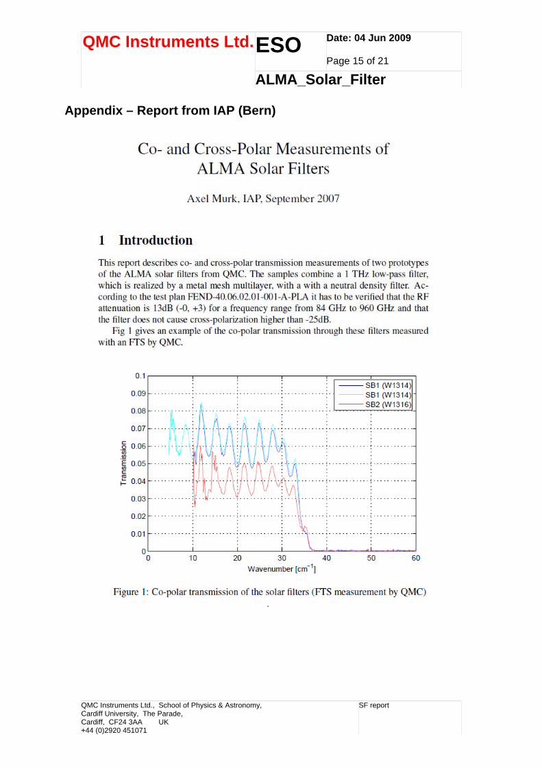
1. Introduction and scope of document 1.1 Introduction QMC Instruments Ltd. (QMCIL) is the commercial partner to the Astronomy Instrumentation Group at Cardiff University (AIG). This partnership has an established reputation for the successful technical development and provision under commercial contract conditions of optical component technology to ALMA and other astronomical projects including space-borne projects such as Herschel (HIFI) and to a number of institutes associated with the ALMA project (ESO, SRON, IRAM, NRAO.) 1.2 Scope of document QMCIL has provided prototype Solar Filters for ALMA under contract PO016292/CNIE dated 17th July 2007 (QMC Project Reference 1264.) The devices were provided with the intention of accordance with the interface documents and technical specifications available at that time (see related document list.) Based on the multi-layer mesh filter technology developed at Cardiff University a design was suggested that involves a composite structure of two elements. The first element is a low-pass filter structure with an edge frequency close to the upper limit of ALMA observations at 960GHz. The second element is a neutral density layer having constant attenuation as a function of frequency throughout the ALMA observing bands. We present in this document optical test data and report our technical appraisal of this solution so that a final specification can be generated to cover the production version of the ALMA Solar Filter. 1.3 Synopsis Two prototype ALMA solar filters (Ref: W1419 + ND#23 and H1424 + ND#24) were supplied in November 2007. The data supplied at the time included co-and cross-polar performance of the filters at near normal incidence (see Figures 4 and 5 in Section 2). These filters were then made available to Dr. Axel Murk (IAP, Bern) who made more detailed measurements in September 2007 which raised further questions. In order to investigate the matter further, measurements were then made on two further prototype filters (Ref: W1377 and W1394.) The behaviour of these latter filters was measured at a representative off-axis angle (7° ) and with respect to rotation of the filters about the beam axis (see Section 3, Figures 6, 7, 8).
QMC Instruments Ltd., School of Physics & Astronomy, Cardiff University, The Parade, Cardiff, CF24 3AA UK +44 (0)2920 451071
SF report
ESO Date: 04 Jun 2009 Page 4 of 21
QMC Instruments Ltd.
ALMA_Solar_Filter
2. Reference Information 2.1 Applicable Documents List (ADL) Item Reference
PO016292/CNIE dated 19th Jul 2007. Contract ALMA-80.05.02.00-001-B-SPE Environmental Specification FEND-40.06.00.00-009-B-SPE (Section 5) Technical specification FEND-40.06.02.05.00-A-ICD Interface Control Document FEND-40.06.02.01-001-A-PLA Performance Test Plan
2.2 Acronyms AIG Astronomy Instrumentation Group (Cardiff University) ALMA Atacama Large Millimetre Array ESO European Southern Observatory FIR Far-Infrared FTS Fourier Transform Spectrometer ND Neutral Density QMCIL QMC Instruments Ltd.
QMC Instruments Ltd., School of Physics & Astronomy, Cardiff University, The Parade, Cardiff, CF24 3AA UK +44 (0)2920 451071
SF report
ESO Date: 04 Jun 2009 Page 5 of 21
QMC Instruments Ltd.
ALMA_Solar_Filter
3. Experimental set-up Measurements were made using the Astronomy Instrumentation Group’s (AIG) rapid-scan Martin-Puplett polarizing FTS, which is illustrated in Figures 1 and 2.
Figure 1. The AIG’s FIR FTS, showing the main body of the interferometer with a cryogenic detector system housed in a red cryostat to the left. When performing the measurements detailed in section 3 of this report, the detector was moved further away from the interferometer in order to allow for the inclusion of a Gaussian beam telescope set-up (see Figure 3.)
QMC Instruments Ltd., School of Physics & Astronomy, Cardiff University, The Parade, Cardiff, CF24 3AA UK +44 (0)2920 451071
SF report
ESO Date: 04 Jun 2009 Page 6 of 21
QMC Instruments Ltd.
ALMA_Solar_Filter
Polarizing Beam
Figure 2. Schematic of the FTS.
Figure 3. Gaussian beam set up with additional polarizers.
Detector
Lens1 Lens 2
Polarizer 2 Polarizer 1
FTS output
Rotating sample stage at 7° incident angle
Output to detector
Divider
Filters and input polarizer
Moving mirror Stationary mirror
Mercury Arc Lamp source Sample chamber
Analyzing polarizer
QMC Instruments Ltd., School of Physics & Astronomy, Cardiff University, The Parade, Cardiff, CF24 3AA UK +44 (0)2920 451071
SF report
ESO Date: 04 Jun 2009 Page 7 of 21
QMC Instruments Ltd.
ALMA_Solar_Filter
4. Initial measurements The FTS and detector combination was configured for optimum performance in the frequency range 5 – 40cm-1 (150 to 1,200GHz.) Initial measurements were made with the solar filters held in the evacuated FTS sample chamber in a co-polar configuration at room temperature. Measurements were taken in transmission through the filters at near-normal incidence. In this way the edge-definition component of the filter could be compared to its modelled performance and verified prior to combining it with the neutral density component. In order to measure the performance of the two combined filter elements in co- and cross-polar designations, a Gaussian beam telescope was set up behind the output port of the interferometer (see Figure 3.) In this configuration the filter is located in a parallel beam and is mounted in a rotator. We also have the ability to vary the angle of incidence of the beam to the filter. Photolithographic polarizers are placed both in front of and behind the filter. These polarizers were carefully aligned both to each other and to the output polarizer of the FTS using a HeNe laser. The polarizers were set at an angle to the sample and to the FTS optical components in order to remove standing waves. For good signal to noise data in co-polar measurements, 3 sets of 10 forward and backward interferograms were averaged then Fourier transformed. These were ratioed against an identical set of background spectra taken with no solar filter in the system. These normalized data therefore show filter transmission efficiency as a function of frequency (cm-1). Figure 4 presents the preliminary co-polar filter data. In the cross-polar arrangement, the difficulty in getting good SNR at such low signals demanded longer integration times. In this case 3 sets of scans of 30 forward and backward averages were taken. The background cross-polar level was also measured. The results are presented in Figure 5. The ALMA specification for these components included:
• A band-edge limitation of 960GHz; • -13dB (+0dB, -3dB) in-band attenuation; • A further -23dB attenuation in cross-polar configuration.
The first requirement of 50% edge cut-off at 960GHz is clearly met. If subsequent scientific discussions reveal a need for a small shift in this edge frequency this can relatively easily be accommodated. The co-polar data show that the initial requirement for -13dB (+0, -3dB) is not met. We believe we understand why this is. We calculated the ND level required based on the transmission level of the original uncoated filter. The subsequent addition of the partially reflecting, partially absorbing ND element is not straightforward. In the combined filter the depth of the filter fringing increases and the ND level is slightly higher than predicted. We
QMC Instruments Ltd., School of Physics & Astronomy, Cardiff University, The Parade, Cardiff, CF24 3AA UK +44 (0)2920 451071
SF report
ESO Date: 04 Jun 2009 Page 8 of 21
QMC Instruments Ltd.
ALMA_Solar_Filter
have performed further tests and can now account for this. However, as can be seen from Figure 4, the combination of the current level specifications and the inherent filter fringing leaves little room for error. We should like to know the important levels (or average) to aim for, and whether these limits can be relaxed at all. Figure 5 demonstrates that cross-polar generation was -40dB on average. This is compliant with the specification. However subsequent measurements performed at by Dr. Axel Murk at IAP Bern (Appendix A) suggested that the level of cross-polar generation is variable with respect to the orientation of the filter about the radiation axis. This conclusion was unexpected and lead to further investigation.
QMC Instruments Ltd., School of Physics & Astronomy, Cardiff University, The Parade, Cardiff, CF24 3AA UK +44 (0)2920 451071
SF report
ESO Date: 04 Jun 2009 Page 9 of 21
QMC Instruments Ltd.
ALMA_Solar_Filter
-17
-16.5
-16
-15.5
-15
-14.5
-14
-13.5
-13
-12.5
-12
-11.5
-11
-10.5
0 5 10 15 20 25 30 35 40
Wavenumber (cm-1)
Tran
smis
sion
dB
H1424 Alma Solar blocker + ND #24 co-pol tilted 7 deg
W1419 Alma Solar blocker + ND #23 co-pol tilted 7 deg
13dB
16dB
Figure 4: Co-pol measurements of prototype solar blocking filters at near-normal incidence.
-55
-50
-45
-40
-35
-30
-25
-20
-15
-10
-5
0 5 10 15 20 25 30 35 40
Wavenumber (cm-1)
Tran
smis
sion
dB
H1424 Alma solar blocker + ND #24 cross pol tilted 7 degrees
W1419 Alma solar blocker + ND #23 cross pol tilted 7 degrees
H1424 Alma Solar blocker + ND #24 co-pol tilted 7 deg
W1419 Alma Solar blocker + ND #23 co-pol tilted 7 deg
Figure 5: Cross-pol measurements of prototype solar blocking filters at 7 degrees incidence.
QMC Instruments Ltd., School of Physics & Astronomy, Cardiff University, The Parade, Cardiff, CF24 3AA UK +44 (0)2920 451071
SF report
ESO Date: 04 Jun 2009 Page 10 of 21
QMC Instruments Ltd.
ALMA_Solar_Filter
5. More Detailed Cross-polar Measurements The measurements performed by Dr. Murk reveal a reproducible variation in cross-polar generation level as a function of the filter rotation angle with respect to the beam axis. This variation was periodic, with a 90° repeat angle. We investigated this further in Cardiff by constructing two further prototype solar filters without ND layers. The active layers within the low-pass element of the solar filters consist of patterns of capacitative copper squares of varying geometries. The filter is assembled by carefully laying these layers on top of each other in a precisely spaced manner. The orientation of each layer with respect to its neighbour is variable, at the discretion of the manufacturer, and a current point of development interest. Filter W1377 was constructed with all its twelve patterned layers aligned as well as possible. Conversely filter W1394 was assembled with its layers non-aligned (i.e each one of 12 layers rotated by approximately 16° with respect to its nearest neighbours). These two filter constructions were chosen to indicate in extreme whether the observed effects are dependent on the geometric grids within the filter. Assuming that this is the case, we wished to ascertain whether a non-aligned filter would produce better cross-polar characteristics than an aligned filter. These filters were tested using the Gaussian beam set-up (Figure 3) described above, and set at 7° to the beam axis. The filters were mounted in a rotator which allowed accurate alignment with respect to the output polarizer of the FTS. 0° was set such that one axis of the Cu square in the patterned layer was aligned to the output polarizer. This angle was then varied in 22.5° steps. The results of our measurements are shown in Figures 6, 7, 8. With reference to Figure 6, at lower frequencies there is little dependence on the cross-polar level for Filter W1377 (with aligned mesh components) with rotation. At the higher frequency end – as we approach the filter band-edge, the angular dependence to the cross-polar generation increases. These measurements were repeated for Filter W1394 (with controlled non-aligned mesh components) – see Figure 7. The low frequency behaviour here is similar to W1377, however there is less sensitivity to angle of rotation at the higher frequencies. For ease of comparison the data of Figures 6 and 7 are overlaid in Figure 8. Using filter W1394 (which gave the largest variation), the cross-polar signal as a function of rotation angle was investigated further. See Figure 9. Data presented are average values integrated across the frequency range 600-750 GHz (20 -25 cm-1), taken in 22.5° increments about a complete rotation.
QMC Instruments Ltd., School of Physics & Astronomy, Cardiff University, The Parade, Cardiff, CF24 3AA UK +44 (0)2920 451071
SF report
ESO Date: 04 Jun 2009 Page 11 of 21
QMC Instruments Ltd.
ALMA_Solar_Filter
Clearly there is a variation in throughput with respect to the filter alignment, periodic over 90°. We initially attributed this effect to interference between the first two metal mesh patterns in the filter and the incident radiation. The largest effect is due to the first mesh. It is important to note that we can relate this behaviour to the orientation of the first mesh layer with respect to the E vector of the incident radiation. Therefore an optimum position can be located. We note that the variations we observe are of reduced amplitude compared to those observed by Dr. Murk. This we attribute to the absence of an ND layer in the filters we tested. In order to verify that the observed behaviour is an interference effect and not a polarization response in any single metal-mesh layer, we performed the same measurements on a single metal mesh layer of the type embedded within the solar filters. The results are presented in Figure 10. Here we see that there is no rotational dependence on the cross polar level.
-55
-45
-35
-25
-15
-5
0 5 10 15 20 25 30 35 40
Wavenumber (cm-1)
Tran
smis
sion
W1377 Alma solar blocker aligned cross pol grids axis vertical 0 degs
W1377 Alma solar blocker aligned cross pol grids axis vertical 22.5 degs
W1377 Alma solar blocker aligned cross pol grids axis vertical 45 degs
W1377 Alma solar blocker aligned cross pol grids axis vertical 67.5 degs
W1377 Alma solar blocker aligned cross pol grids axis vertical 90 degs
Figure 6: Transmission spectra for Filter W1377 (with aligned mesh components) as a function of rotation about the beam axis.
QMC Instruments Ltd., School of Physics & Astronomy, Cardiff University, The Parade, Cardiff, CF24 3AA UK +44 (0)2920 451071
SF report
ESO Date: 04 Jun 2009 Page 12 of 21
QMC Instruments Ltd.
ALMA_Solar_Filter
-50
-45
-40
-35
-30
-25
-20
-15
-10
-5
0
0 5 10 15 20 25 30 35 40
Wavenumber (cm-1)
Tran
smis
sion
W1394 Alma solar blocker non-aligned (~16 degrees)
W1394 Alma solar blocker non-aligned (~16 degrees)
W1394 Alma solar blocker non-aligned (90 degrees) 7deg tilt max
W1394 Alma solar blocker non-aligned (45 degrees) 7deg tilt min
0 degs
22.5 degs
45 degs
67.5 degs
Figure 7: Transmission spectra for Filter W1394 (with controlled non-aligned mesh components) as a function of rotation about the beam axis.
-55
-50
-45
-40
-35
-30
-25
-20
-15
5 10 15 20 25 30 35
Wavenumber (cm-1)
Tra
nsm
issi
on
40
W1394 Alma solar blocker non-aligned (~16 degrees) W1394 Alma solar blocker non-aligned (~16 degrees)
W1394 Alma solar blocker non-aligned (90 degrees) 7deg tilt max W1394 Alma solar blocker non-aligned (45 degrees) 7deg tilt min
W1377 Alma solar blocker aligned grids co pol W1377 Alma solar blocker aligned cross pol grids axis vertical 0 degs
W1377 Alma solar blocker aligned cross pol grids axis vertical 67.5 degs W1377 Alma solar blocker aligned cross pol grids axis vertical 22.5 degs
W1377 Alma solar blocker aligned cross pol grids axis vertical 45 degs W1377 Alma solar blocker aligned cross pol grids axis vertical 90 degs
Figure 8: Overlay of the all results for both filters (from Figures 6 and 7), showing a similar minimum cross-pol for both filters. However the variation in the cross-pol seems to be minimised in a between a non-aligned filter.
QMC Instruments Ltd., School of Physics & Astronomy, Cardiff University, The Parade, Cardiff, CF24 3AA UK +44 (0)2920 451071
SF report
ESO Date: 04 Jun 2009 Page 13 of 21
QMC Instruments Ltd.
ALMA_Solar_Filter
-40
-39
-38
-37
-36
-35
-34
-33
-32
-31
-30
0 45 90 135 180 225 270 315 360
Rotation Angle (degrees)
Cro
ss_p
ol
Figure 9: A measurement of the average cross-pol transmission for filter W1394 as a function of rotation about the beam axis.
-55
-45
-35
-25
-15
-5
0 5 10 15 20 25 30 35 40
Wavenumber (cm-1)
Tran
smis
sion
C200 single grid grid aligned with vertical 0 degs co Pol
C200 single grid grid 0 degs cross Pol
C200 single grid grid 22.5 degs cross Pol
C200 single grid grid 45 degs cross Pol
C200 single grid grid 67.5 degs cross Pol
Crossed Polarisers
Figure 10: Cross pol. Measurements on a single metal mesh layer. This shows no rotational dependence on the level of transmitted cross pol. Therefore supporting theory that the effect observed in the filter is due in some part to reflections between the 1st nd and 2 metal-mesh layers.
QMC Instruments Ltd., School of Physics & Astronomy, Cardiff University, The Parade, Cardiff, CF24 3AA UK +44 (0)2920 451071
SF report
ESO Date: 04 Jun 2009 Page 14 of 21
QMC Instruments Ltd.
ALMA_Solar_Filter
6. Conclusions
• We seek confirmation that the current design of the filter with 960GHz edge position is satisfactory. The solar filter becomes more polarization sensitive toward the high frequency end of the pass-band. This is inherent filter behaviour and, if this is a problem in-band, the filter edge position can be moved to a higher frequency.
• We need to know the final requirement on the in-band levels. Do we seek to meet an average in-band requirement or a maximum level that should not be exceeded? Can the 3dB range be extended at all?
• Measuring the filters at 7° to the beam incidence has no effect on their performance. This is as expected – we usually state that filters will maintain good transmission performance at up to 22° incidence.
• Having learnt the effect that the addition of the ND has on the performance of the filter, we are in a better position to meet the required in-band co-pol level.
• We will manufacture future solar blockers of the non-aligned type. • Needing to orient the filters in their filter wheel, so as to meet the cross-pol
specification, we will need to mark a maximum (or minimum) orientation on the filter. This will need to co-locate with an agreed mark on the filter mounts. We need to agree this position.
QMC Instruments Ltd., School of Physics & Astronomy, Cardiff University, The Parade, Cardiff, CF24 3AA UK +44 (0)2920 451071
SF report
ESO Date: 04 Jun 2009 Page 15 of 21
QMC Instruments Ltd.
ALMA_Solar_Filter
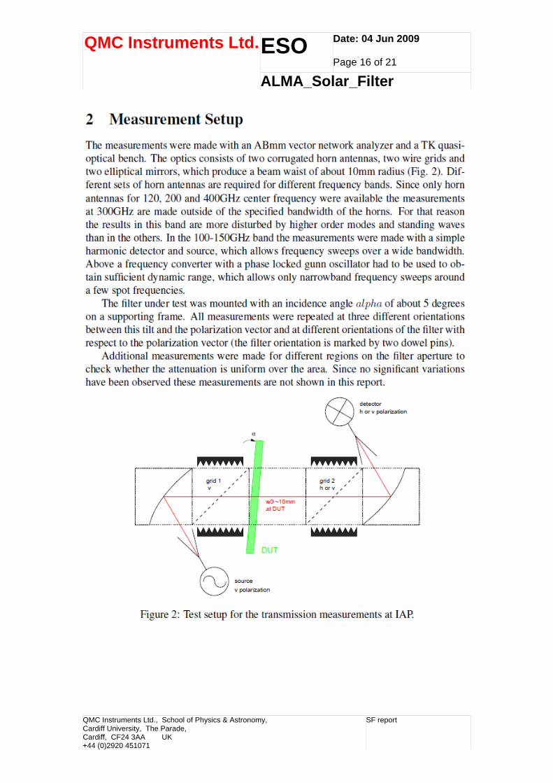
Appendix – Report from IAP (Bern)
QMC Instruments Ltd., School of Physics & Astronomy, Cardiff University, The Parade, Cardiff, CF24 3AA UK +44 (0)2920 451071
SF report
ESO Date: 04 Jun 2009 Page 16 of 21
QMC Instruments Ltd.
ALMA_Solar_Filter
QMC Instruments Ltd., School of Physics & Astronomy, Cardiff University, The Parade, Cardiff, CF24 3AA UK +44 (0)2920 451071
SF report
ESO Date: 04 Jun 2009 Page 17 of 21
QMC Instruments Ltd.
ALMA_Solar_Filter
QMC Instruments Ltd., School of Physics & Astronomy, Cardiff University, The Parade, Cardiff, CF24 3AA UK +44 (0)2920 451071
SF report
ESO Date: 04 Jun 2009 Page 18 of 21
QMC Instruments Ltd.
ALMA_Solar_Filter
QMC Instruments Ltd., School of Physics & Astronomy, Cardiff University, The Parade, Cardiff, CF24 3AA UK +44 (0)2920 451071
SF report
ESO Date: 04 Jun 2009 Page 19 of 21
QMC Instruments Ltd.
ALMA_Solar_Filter
QMC Instruments Ltd., School of Physics & Astronomy, Cardiff University, The Parade, Cardiff, CF24 3AA UK +44 (0)2920 451071
SF report
ESO Date: 04 Jun 2009 Page 20 of 21
QMC Instruments Ltd.
ALMA_Solar_Filter
QMC Instruments Ltd., School of Physics & Astronomy, Cardiff University, The Parade, Cardiff, CF24 3AA UK +44 (0)2920 451071
SF report
ESO Date: 04 Jun 2009 Page 21 of 21
QMC Instruments Ltd.
ALMA_Solar_Filter
END OF DOCUMENT
QMC Instruments Ltd., School of Physics & Astronomy, Cardiff University, The Parade, Cardiff, CF24 3AA UK +44 (0)2920 451071