Collinear Microstrip Patch Antennas 513 x Collinear Microstrip Patch Antennas Alois Holub and Milan Polívka Czech Technical University in Prague Czech Republic 1. Introduction The original idea of the collinear principle in the antenna design comes from Franklin (Franklin, 1925). He faced the problem of resonant long wire antennas. In principle, the standing wave current distribution on the long straight wire produces n radiation lobes of the same level, depending on the number n of half-wave antenna sections. Employing non- radiating quarter-wave stubs Franklin converted the original out-phase current distribution into an in-phased distribution of currents on collinear segments (represented by solid red arrows in Fig. 1), thus producing only one major radiation beam. A key advantage of such arrangement is represented by the high gain of the antenna with the properties of series antenna array, whereas the simplicity of the single feeding point is maintained. All antenna structures based on this principle are known as collinear arrays (CoA). The latter are composed of in-phase fed radiating elements that lie in the straight line. Their radiation is typically broadside and perpendicular to the axis of collinear elements. Since Franklin’s times many collinear antenna structures have been proposed. The principle representatives of the CoA are described later on. Fig. 1. Sketch of vector current distributed on original Franklin collinear wire dipole. Only collinear segments provide in-phase current distribution and contribute to radiation. The first coaxial collinear (CoCo) antenna was proposed in 1972 (Balsley & Ecklund, 1972). It is constructed of series of half-wavelengths of the coaxial cable connected together by an electrically interchanging of the inner-and outer-conductors at each junction, see Fig. 2. From the physical point of view, the resulting antenna takes form of a one single long section of exible coaxial line. Nevertheless, from the electrical point of view, it is composed of a number of collinear half-wave dipoles fed in phase. Although the principle of operation of the CoCo antenna is based on the Franklin’s idea, the concept of radiating coaxial is far more complex. Due to the Ampere’s circuital law, the currents in the inner line conductor and on the inside surface of the outer line conductor must be equal and opposite. Referring 24 www.intechopen.com
Transcript
Collinear Microstrip Patch Antennas 513
Collinear Microstrip Patch Antennas
Alois Holub and Milan Polívka
x
Collinear Microstrip Patch Antennas
Alois Holub and Milan Polívka Czech Technical University in Prague
Czech Republic
1. Introduction
The original idea of the collinear principle in the antenna design comes from Franklin (Franklin, 1925). He faced the problem of resonant long wire antennas. In principle, the standing wave current distribution on the long straight wire produces n radiation lobes of the same level, depending on the number n of half-wave antenna sections. Employing non-radiating quarter-wave stubs Franklin converted the original out-phase current distribution into an in-phased distribution of currents on collinear segments (represented by solid red arrows in Fig. 1), thus producing only one major radiation beam. A key advantage of such arrangement is represented by the high gain of the antenna with the properties of series antenna array, whereas the simplicity of the single feeding point is maintained. All antenna structures based on this principle are known as collinear arrays (CoA). The latter are composed of in-phase fed radiating elements that lie in the straight line. Their radiation is typically broadside and perpendicular to the axis of collinear elements. Since Franklin’s times many collinear antenna structures have been proposed. The principle representatives of the CoA are described later on.
Fig. 1. Sketch of vector current distributed on original Franklin collinear wire dipole. Only collinear segments provide in-phase current distribution and contribute to radiation. The first coaxial collinear (CoCo) antenna was proposed in 1972 (Balsley & Ecklund, 1972). It is constructed of series of half-wavelengths of the coaxial cable connected together by an electrically interchanging of the inner-and outer-conductors at each junction, see Fig. 2. From the physical point of view, the resulting antenna takes form of a one single long section of exible coaxial line. Nevertheless, from the electrical point of view, it is composed of a number of collinear half-wave dipoles fed in phase. Although the principle of operation of the CoCo antenna is based on the Franklin’s idea, the concept of radiating coaxial is far more complex. Due to the Ampere’s circuital law, the currents in the inner line conductor and on the inside surface of the outer line conductor must be equal and opposite. Referring
24
www.intechopen.com
Passive Microwave Components and Antennas514
to Fig. 2, it is obvious that one feeder feeds two coaxial lines only. Consequently, there can be no current over the outer cable conductor. This current represents the antenna radiating current. In fact, the generator excites two antennas (one starting with the outer line conductor, whereas the other with the inner line conductor). Therefore, both of these two antennas are fed 180° out of phase. Consequently, there will be a non-zero total current along the coaxial-line sections, i.e., a radiating current. A frequently presented variation of the described CoCo antenna is the monopole concept over the ground plane. Further electromagnetically coupled coaxial dipole array antenna has been proposed as a modification of the CoCo (Miyashita et al., 1999).
Fig. 2. Coaxial collinear (CoCo) antenna with a sketch of vector current distribution Franklin-type microstrip line antenna (Nishimura et al, 1979) was probably one of the rst microstrip line type antennas based on the collinear principle. The antenna conguration and the current distribution on the radiating microstrip line are depicted in Fig. 3a. The operational principle is based on a presumption that, in general, a non-radiating microstrip line can be manufactured and used in order to radiate by means of the suitable bending of the strip conductor. The aforementioned bending perturbs transmission characteristics of the microstrip line periodically; thereby it operates as a linear array antenna. The presented shape of the microstrip turns out to be very effective, because even the phasing stubs contribute to the radiation. The microstrip is designed for 50 Ω. The end of the microstrip line is terminated by an open-circuit. When the lengths of the straight section and the bending section (see Fig. 3a) are set at the level of about one-half of guide wavelength, the eventual current distribution can be represented by the arrow. As a result, the direction of the radiation is broadside of the array and the polarization is parallel to the straight section.
Fig. 3. Franklin-type microstrip line antenna a) and Microstrip-Franklin antenna b) with a vector current distribution Another microstrip antenna derived from the Franklin’s collinear idea was the Microstrip-Franklin antenna (Solbach, 1982). The layout of the structure is shown in Fig. 3b). Unlike the
CoCo antenna, the principle of the operation is more similar to the Franklin’s folded wire. Solbach started with the endeavour to suppress the radiation of the half-wavelength connecting lines situated between the patch radiators in microstrip array. In comparison with Franklin, he proposed two 100 Ω quarter-wave phasing stubs, producing a 180° phase shift between the terminals of the microstrip transmission lines. The stubs were designed symmetrically in order to maintain the parasitic discontinuity effects at the junction of stub and microstrip patch on the low levels. The currents on the phasing stubs are mutually opposite in direction so that the radiation produced by the stubs is cancelled. Nevertheless, the electrical fringe elds of the terminating microstrip lines superimpose the phase in the slot between the lines. The resulting electric eld in the slot was revealed as a prevailing source of radiation in the arrangement; see Fig. 3b). Such phasing stub can be described as a slot radiator embedded into the microstrip line and employing the radiators in question. It is possible to design the antenna array with a low spurious radiation and also a low surface wave excitation. One of the latest structures with applied omnidirectional principle to the microstrip structure is represented by the Omnidirectional Planar Microstrip Antenna (OMA) (Bancroft and Bateman, 2004). The geometry of the OMA is presented in Fig. 4. The antenna consists of top and bottom traces. The top layer traces range from wide to narrow, while complementing the narrow to wide traces on the bottom layer. The antenna is fed with a probe at the junction of the rst narrow line and the next wide section connection. The principle of operation is similar to the CoCo antenna, since all wide half-wavelength parts of the antenna radiate. The radiation is omnidirectional, because the odd and even half-wavelength wide section radiate in opposite directions. The impedance matching is achieved by variations of the value of W2.
Fig. 4. Omnidirectional microstrip line antenna with a sketch of vector current distribution Another collinear type antenna is represented by an arrangement of folded slot analogues to the wire type, e.g. (Chen et al., 2007). The next chapters are going to deal with the development and efficient analysis of a novel arrangement of collinear antenna in the microstrip technology providing hemispherical pattern called Collinear Microstrip Patch Antenna (CoMPA) (Polívka & Holub, 2005).
www.intechopen.com
Collinear Microstrip Patch Antennas 515
to Fig. 2, it is obvious that one feeder feeds two coaxial lines only. Consequently, there can be no current over the outer cable conductor. This current represents the antenna radiating current. In fact, the generator excites two antennas (one starting with the outer line conductor, whereas the other with the inner line conductor). Therefore, both of these two antennas are fed 180° out of phase. Consequently, there will be a non-zero total current along the coaxial-line sections, i.e., a radiating current. A frequently presented variation of the described CoCo antenna is the monopole concept over the ground plane. Further electromagnetically coupled coaxial dipole array antenna has been proposed as a modification of the CoCo (Miyashita et al., 1999).
Fig. 2. Coaxial collinear (CoCo) antenna with a sketch of vector current distribution Franklin-type microstrip line antenna (Nishimura et al, 1979) was probably one of the rst microstrip line type antennas based on the collinear principle. The antenna conguration and the current distribution on the radiating microstrip line are depicted in Fig. 3a. The operational principle is based on a presumption that, in general, a non-radiating microstrip line can be manufactured and used in order to radiate by means of the suitable bending of the strip conductor. The aforementioned bending perturbs transmission characteristics of the microstrip line periodically; thereby it operates as a linear array antenna. The presented shape of the microstrip turns out to be very effective, because even the phasing stubs contribute to the radiation. The microstrip is designed for 50 Ω. The end of the microstrip line is terminated by an open-circuit. When the lengths of the straight section and the bending section (see Fig. 3a) are set at the level of about one-half of guide wavelength, the eventual current distribution can be represented by the arrow. As a result, the direction of the radiation is broadside of the array and the polarization is parallel to the straight section.
Fig. 3. Franklin-type microstrip line antenna a) and Microstrip-Franklin antenna b) with a vector current distribution Another microstrip antenna derived from the Franklin’s collinear idea was the Microstrip-Franklin antenna (Solbach, 1982). The layout of the structure is shown in Fig. 3b). Unlike the
CoCo antenna, the principle of the operation is more similar to the Franklin’s folded wire. Solbach started with the endeavour to suppress the radiation of the half-wavelength connecting lines situated between the patch radiators in microstrip array. In comparison with Franklin, he proposed two 100 Ω quarter-wave phasing stubs, producing a 180° phase shift between the terminals of the microstrip transmission lines. The stubs were designed symmetrically in order to maintain the parasitic discontinuity effects at the junction of stub and microstrip patch on the low levels. The currents on the phasing stubs are mutually opposite in direction so that the radiation produced by the stubs is cancelled. Nevertheless, the electrical fringe elds of the terminating microstrip lines superimpose the phase in the slot between the lines. The resulting electric eld in the slot was revealed as a prevailing source of radiation in the arrangement; see Fig. 3b). Such phasing stub can be described as a slot radiator embedded into the microstrip line and employing the radiators in question. It is possible to design the antenna array with a low spurious radiation and also a low surface wave excitation. One of the latest structures with applied omnidirectional principle to the microstrip structure is represented by the Omnidirectional Planar Microstrip Antenna (OMA) (Bancroft and Bateman, 2004). The geometry of the OMA is presented in Fig. 4. The antenna consists of top and bottom traces. The top layer traces range from wide to narrow, while complementing the narrow to wide traces on the bottom layer. The antenna is fed with a probe at the junction of the rst narrow line and the next wide section connection. The principle of operation is similar to the CoCo antenna, since all wide half-wavelength parts of the antenna radiate. The radiation is omnidirectional, because the odd and even half-wavelength wide section radiate in opposite directions. The impedance matching is achieved by variations of the value of W2.
Fig. 4. Omnidirectional microstrip line antenna with a sketch of vector current distribution Another collinear type antenna is represented by an arrangement of folded slot analogues to the wire type, e.g. (Chen et al., 2007). The next chapters are going to deal with the development and efficient analysis of a novel arrangement of collinear antenna in the microstrip technology providing hemispherical pattern called Collinear Microstrip Patch Antenna (CoMPA) (Polívka & Holub, 2005).
www.intechopen.com
Passive Microwave Components and Antennas516
As it is going to be demonstrated, the latter can also be modularly extended in area for higher gain (Polívka & Holub, 2006).
2. Development of Collinear Microstrip Patch Antennas
This section is based on the explanation presented for the first time in papers (Polívka & Holub, 2005) and (Polívka & Holub, 2006). It describes the operational principle of a novel type of collinear antenna array, designed and realized in the microstrip patch antenna technology. The operational principle is explained via surface current distribution on the patch in the way analogical to the case of Franklin wire CoA. The performance of the antenna principle is verified on the realized prototypes for 869 MHz RFID and 2.4 GHz ISM bands, which are employed in the real applications.
2.1 Principle of CoMPA operation Firstly, let us explain the meaning of the following three expressions frequently used in the microstrip patch antenna technology: radiator, patch and motif. The term ‘radiator’ stand for a complete radiating element that includes the ground plane. ‘Patch‘ is a conductive part of a radiator that is situated in the height h above the ground plane. The term ‘motif‘ is used for a particular geometrical shape of the patch. The principle of the operation of CoMPA is based on the application of geometrical ‘perturbation elements‘, i.e. slots and notches introduced in the patch that, itself, operates on higher order modes. In our case, the antenna resonates dominantly on the TM0X mode, where X determines the number of current half-wavelengths in the resonant longitudinal dimension of the patch (in figures indicated on the y-axis). The impact of the perturbation elements can be explained as the way how to eliminate the radiation from even out-phase electric current distribution, which is forced to flow round these elements. This approach is analogous to the application of λ/4 curved sections in the Franklin wire antenna. From the point of view of the radiation pattern calculation, the slots (and notches) can be put together with outer radiation edges that are considered as a radiation source in case that the equivalent method of magnetic currents is used. The E-field distribution along the external perpendicular edges is nearly constant. On the contrary the E-field distribution along the inner slots reaches its maximum in the center, but shows degressive trend in its value as long as it approaches the slot edges, which corresponds to the currents flowing around. A detailed analysis of the E-field distribution along the edges of the CoMPA represents the objective of Chapter 3. Vector surface current distributions on the CoMPAs, operating on the mode TM03 and TM05 are demonstrated in Fig. 5. The CoMPA operating with TM03 mode (CoMPA03) with one central narrow slot constitutes the simplest example of the implementation of the above-described principle.. The slot of the length of approx. λg/2 and the width of a fragment of λg makes the second (even) current wavelength to flow around (see Fig. 5a). The same effect can be explained in case of CoMPA operating on the mode TM05 (CoMPA05) (see Fig. 5b). The optimized dimensions of CoMPA05 scaled to the wavelength are depicted in Fig. 5c. The solid red and dash blue arrows represent the in-phase (approx. λg/2 long) and out-phase (approx. λg/5 long) source areas, respectively. Physical dimensions of the realized antenna prototype (see Fig. 6a) are listed below: patch size 268 × 643 mm, slot length 172.5 mm and ground plane size 298 × 680 mm. The patch is
carried by plastic distance posts located over the ground plane at the height of 10 mm (approx. 0.03 λ0). The distance between the coaxial feed placed on the y-axis and the inner edge of one of the slots equals approx. 0.047 λg. All the structure was modeled in the IE3D method of moment simulation tool with a finite ground plane.
a) b) c)
Fig. 5. Vector surface current distribution represented by black arrows (simulated by IE3D) on the patch of the CoMPA operating on mode a) TM03, and b) TM05. c) Scheme of the CoMPA05 with dimensions related to the wavelength with schematic current distribution. The measured reflection coefficients of the realized prototype with and without a hardened polystyren (HPS) radom of 3 mm thickness placed at the height of 40 mm over the patch is illustrated in Fig. 6b.
a) b) Fig. 6. a) Photograph of CoMPA05 prototype for 869 MHz band, b) measured reflection coeffcient of realized prototype with depicted influence of HPS radom.
www.intechopen.com
Collinear Microstrip Patch Antennas 517
As it is going to be demonstrated, the latter can also be modularly extended in area for higher gain (Polívka & Holub, 2006).
2. Development of Collinear Microstrip Patch Antennas
This section is based on the explanation presented for the first time in papers (Polívka & Holub, 2005) and (Polívka & Holub, 2006). It describes the operational principle of a novel type of collinear antenna array, designed and realized in the microstrip patch antenna technology. The operational principle is explained via surface current distribution on the patch in the way analogical to the case of Franklin wire CoA. The performance of the antenna principle is verified on the realized prototypes for 869 MHz RFID and 2.4 GHz ISM bands, which are employed in the real applications.
2.1 Principle of CoMPA operation Firstly, let us explain the meaning of the following three expressions frequently used in the microstrip patch antenna technology: radiator, patch and motif. The term ‘radiator’ stand for a complete radiating element that includes the ground plane. ‘Patch‘ is a conductive part of a radiator that is situated in the height h above the ground plane. The term ‘motif‘ is used for a particular geometrical shape of the patch. The principle of the operation of CoMPA is based on the application of geometrical ‘perturbation elements‘, i.e. slots and notches introduced in the patch that, itself, operates on higher order modes. In our case, the antenna resonates dominantly on the TM0X mode, where X determines the number of current half-wavelengths in the resonant longitudinal dimension of the patch (in figures indicated on the y-axis). The impact of the perturbation elements can be explained as the way how to eliminate the radiation from even out-phase electric current distribution, which is forced to flow round these elements. This approach is analogous to the application of λ/4 curved sections in the Franklin wire antenna. From the point of view of the radiation pattern calculation, the slots (and notches) can be put together with outer radiation edges that are considered as a radiation source in case that the equivalent method of magnetic currents is used. The E-field distribution along the external perpendicular edges is nearly constant. On the contrary the E-field distribution along the inner slots reaches its maximum in the center, but shows degressive trend in its value as long as it approaches the slot edges, which corresponds to the currents flowing around. A detailed analysis of the E-field distribution along the edges of the CoMPA represents the objective of Chapter 3. Vector surface current distributions on the CoMPAs, operating on the mode TM03 and TM05 are demonstrated in Fig. 5. The CoMPA operating with TM03 mode (CoMPA03) with one central narrow slot constitutes the simplest example of the implementation of the above-described principle.. The slot of the length of approx. λg/2 and the width of a fragment of λg makes the second (even) current wavelength to flow around (see Fig. 5a). The same effect can be explained in case of CoMPA operating on the mode TM05 (CoMPA05) (see Fig. 5b). The optimized dimensions of CoMPA05 scaled to the wavelength are depicted in Fig. 5c. The solid red and dash blue arrows represent the in-phase (approx. λg/2 long) and out-phase (approx. λg/5 long) source areas, respectively. Physical dimensions of the realized antenna prototype (see Fig. 6a) are listed below: patch size 268 × 643 mm, slot length 172.5 mm and ground plane size 298 × 680 mm. The patch is
carried by plastic distance posts located over the ground plane at the height of 10 mm (approx. 0.03 λ0). The distance between the coaxial feed placed on the y-axis and the inner edge of one of the slots equals approx. 0.047 λg. All the structure was modeled in the IE3D method of moment simulation tool with a finite ground plane.
a) b) c)
Fig. 5. Vector surface current distribution represented by black arrows (simulated by IE3D) on the patch of the CoMPA operating on mode a) TM03, and b) TM05. c) Scheme of the CoMPA05 with dimensions related to the wavelength with schematic current distribution. The measured reflection coefficients of the realized prototype with and without a hardened polystyren (HPS) radom of 3 mm thickness placed at the height of 40 mm over the patch is illustrated in Fig. 6b.
a) b) Fig. 6. a) Photograph of CoMPA05 prototype for 869 MHz band, b) measured reflection coeffcient of realized prototype with depicted influence of HPS radom.
www.intechopen.com
Passive Microwave Components and Antennas518
The measured radiation patterns are presented in Fig. 7. The distance between the center of odd in-phase rectangular parts is equal to approx. 0.65 λ0, which explains the sidelobe level of about -13 dB similarly to the 0.5 λ0 spaced uniform array. The front-back ratio is approx. 19 dB in the E-plane, although the ground plane dimensions exceed the size of the patch itself by only some 0.1 λ0 (!). The antenna gain without cover has been measured by means of the substitution method at 869.5 MHz in the antenna anechoic chamber (Mazánek et al., 2000). The simulated values of the directivity 12.6 dBi and gain 12.4 dBi (the corresponding efficiency amounts to 95 %) are slightly higher than the measured gain 11.7 dBi. This phenomenon can result from the fabrication tolerance on one hand and the presupposed gain measurement error, which equals at least +/-0.5 dBi on the other hand.. The radiation of the antenna is directional in the E-plane and wider in the H-plane, which corresponds to the linear array of radiators in the y-axis. The measured 3dB beamwidth of 25° in the E-plane and of 65° in the H-plane confirms the gain enhancement (when compared to the gain of the standard rectangular microstrip patch operating on TM01 mode). In fact, the aforementioned gain reaches approx. 6-9 dBi, indeed depending on the heigth and the substrate used. The value of the impedance bandwidth BW = 2.8 % (related to VSWR = 2) is relatively low. It arises from the resonant character of the structure as it is expected in case of the patch-type antennas. In case of a particular RFID application at 869 MHz, where this prototype was used (Švanda et al., 2007), the impedance bandwidth is sufficient, because merely the 250 kHz band was required.
a) b)
Fig. 7. Measured co-polar (Eco) and cross-polar (Ex) radiation patterns of CoMPA05 for 869 MHz band in a) E-plane, and b) H-plane.
2.2 Planar extension of CoMPA All examples of collinear antennas introduced in the first state-of-the-art chapter have one quality in common – each design can be considered as a linear antenna array. However, the principle of CoMPA in the microstrip patch technology enables the extension of the structure perpendicularly to the longitudinal axis of the array. This measure is introduced in the following text. The essence of this lateral extension of currents is similar to the principle used in the grid flat-panel array (Kraus & Marhefka, 2002). The first stage of the explanation has to be dedicated to the structure operating on the TM03 mode, i.e. CoMPA03. The latter can be considered as a linear array of radiators, which can be
laterally extended. Yet in order to preserve the surface current distribution, it is indispensable to add a pair of lateral notches. These notches (of the length of approx. λg/4 ) are placed perpendicularly to the patch border, at the same y-coordinates as the slots. In consequence, the current distribution of the TM03 mode remains the same as on CoMPA. In addition, the similar phenomenon of currents that flow around the notches is maintained (see Fig. 8a). As a result, the Jy component plays a dominant role on the surface of the patch and the radiator exhibits a broadside hemispherical radiation with an enhanced gain. The domination of the Jy component on the majority of the patch surface is a crucial condition for maintainance of a reasonably low cross-polar level. Due to the fact that the area of radiating sources was extended, a higher level of directivity is presumed. By combining longitudinal and lateral extensions of CoMPA03, a motif with two central slots and two pairs of lateral notches operating on TM05 mode (called planar CoMPA; hereinafter referred to as PCOMPA05) is realized (see Fig. 8b). Fig. 8c shows PCoMPA05 motif divided by vertical and horizontal dashed lines into basic modules that form building blocks of the previously elaborated less complex versions of discussed PCoMPAs. The horizontal dashed lines divide the motif into areas with opposite orientation of the surface currents. These currents are denoted in the same fashion as in Fig. 5c, i.e. by solid red and dash blue arrows. The solid red arrows represent the in-phase regions, where the surface currents are nearly straight and oriented towards the y-axis (they are approximately λg/2 high). On the contrary, the dash blue arrows illustrate the out-phase regions, where the surface currents flow around the slots and notches. As a consequence, in the latter type the currents are oriented mostly towards the x-axis (their high is of approximately λg/5).
a) b) c)
Fig. 8. Vector surface current distribution represented by black arrows on PCoMPA with a) TM03 and b) TM05 modes (simulated by IE3D). c) Scheme of PCoMPA05 showing separation to basic segments and line demarking in-phase and out-phase current source areas The initial design of the PCoMPA05 antenna prototype that is developed for 2.4 GHz band is based on the principle described above. The center design frequency was set to 2.44 GHz and the antenna initial dimensions were optimized by means of build in procedures of IE3D simulator, where the criteria of impedance matching and maximum gain were followed. Physical dimensions of the final antenna prototype follow: patch size 189 × 222 mm, slot length 56 mm, notches length 28 mm and ground plane size 240 × 260 mm. The patch is carried over the ground plane by plastic distance posts (in the simulation, this fact was
www.intechopen.com
Collinear Microstrip Patch Antennas 519
The measured radiation patterns are presented in Fig. 7. The distance between the center of odd in-phase rectangular parts is equal to approx. 0.65 λ0, which explains the sidelobe level of about -13 dB similarly to the 0.5 λ0 spaced uniform array. The front-back ratio is approx. 19 dB in the E-plane, although the ground plane dimensions exceed the size of the patch itself by only some 0.1 λ0 (!). The antenna gain without cover has been measured by means of the substitution method at 869.5 MHz in the antenna anechoic chamber (Mazánek et al., 2000). The simulated values of the directivity 12.6 dBi and gain 12.4 dBi (the corresponding efficiency amounts to 95 %) are slightly higher than the measured gain 11.7 dBi. This phenomenon can result from the fabrication tolerance on one hand and the presupposed gain measurement error, which equals at least +/-0.5 dBi on the other hand.. The radiation of the antenna is directional in the E-plane and wider in the H-plane, which corresponds to the linear array of radiators in the y-axis. The measured 3dB beamwidth of 25° in the E-plane and of 65° in the H-plane confirms the gain enhancement (when compared to the gain of the standard rectangular microstrip patch operating on TM01 mode). In fact, the aforementioned gain reaches approx. 6-9 dBi, indeed depending on the heigth and the substrate used. The value of the impedance bandwidth BW = 2.8 % (related to VSWR = 2) is relatively low. It arises from the resonant character of the structure as it is expected in case of the patch-type antennas. In case of a particular RFID application at 869 MHz, where this prototype was used (Švanda et al., 2007), the impedance bandwidth is sufficient, because merely the 250 kHz band was required.
a) b)
Fig. 7. Measured co-polar (Eco) and cross-polar (Ex) radiation patterns of CoMPA05 for 869 MHz band in a) E-plane, and b) H-plane.
2.2 Planar extension of CoMPA All examples of collinear antennas introduced in the first state-of-the-art chapter have one quality in common – each design can be considered as a linear antenna array. However, the principle of CoMPA in the microstrip patch technology enables the extension of the structure perpendicularly to the longitudinal axis of the array. This measure is introduced in the following text. The essence of this lateral extension of currents is similar to the principle used in the grid flat-panel array (Kraus & Marhefka, 2002). The first stage of the explanation has to be dedicated to the structure operating on the TM03 mode, i.e. CoMPA03. The latter can be considered as a linear array of radiators, which can be
laterally extended. Yet in order to preserve the surface current distribution, it is indispensable to add a pair of lateral notches. These notches (of the length of approx. λg/4 ) are placed perpendicularly to the patch border, at the same y-coordinates as the slots. In consequence, the current distribution of the TM03 mode remains the same as on CoMPA. In addition, the similar phenomenon of currents that flow around the notches is maintained (see Fig. 8a). As a result, the Jy component plays a dominant role on the surface of the patch and the radiator exhibits a broadside hemispherical radiation with an enhanced gain. The domination of the Jy component on the majority of the patch surface is a crucial condition for maintainance of a reasonably low cross-polar level. Due to the fact that the area of radiating sources was extended, a higher level of directivity is presumed. By combining longitudinal and lateral extensions of CoMPA03, a motif with two central slots and two pairs of lateral notches operating on TM05 mode (called planar CoMPA; hereinafter referred to as PCOMPA05) is realized (see Fig. 8b). Fig. 8c shows PCoMPA05 motif divided by vertical and horizontal dashed lines into basic modules that form building blocks of the previously elaborated less complex versions of discussed PCoMPAs. The horizontal dashed lines divide the motif into areas with opposite orientation of the surface currents. These currents are denoted in the same fashion as in Fig. 5c, i.e. by solid red and dash blue arrows. The solid red arrows represent the in-phase regions, where the surface currents are nearly straight and oriented towards the y-axis (they are approximately λg/2 high). On the contrary, the dash blue arrows illustrate the out-phase regions, where the surface currents flow around the slots and notches. As a consequence, in the latter type the currents are oriented mostly towards the x-axis (their high is of approximately λg/5).
a) b) c)
Fig. 8. Vector surface current distribution represented by black arrows on PCoMPA with a) TM03 and b) TM05 modes (simulated by IE3D). c) Scheme of PCoMPA05 showing separation to basic segments and line demarking in-phase and out-phase current source areas The initial design of the PCoMPA05 antenna prototype that is developed for 2.4 GHz band is based on the principle described above. The center design frequency was set to 2.44 GHz and the antenna initial dimensions were optimized by means of build in procedures of IE3D simulator, where the criteria of impedance matching and maximum gain were followed. Physical dimensions of the final antenna prototype follow: patch size 189 × 222 mm, slot length 56 mm, notches length 28 mm and ground plane size 240 × 260 mm. The patch is carried over the ground plane by plastic distance posts (in the simulation, this fact was
www.intechopen.com
Passive Microwave Components and Antennas520
neglected) at the height of 5 mm (approx. 0.04 λ0). The patch is fed by a coaxial probe placed on the y–axis at the distance of around 0.047 λg above one of the slots. Measured and simulated reflection coefficients of the realized prototype are depicted in Fig. 9b.
a) b)
-30
-25
-20
-15
-10
-5
0
2300 2350 2400 2450 2500 2550 2600frequency [MHz]
refle
ctio
n co
effic
ient
[dB
]
measurement
simulation
Fig. 9. a) Photograph of realized PCoMPA05 prototype, b) measured and simulated reflection coefficient The distance between the centers of the in-phase source current areas equal 0.68 λ0. Consequently, similarly to the case of 0.5 λ0 element spacing in the linear uniform array, the sidelobe level is equal to about -10 dB. The front-back ratio is approximately 20 dB in both, the E plane and H plane. However, the ground plane dimensions exceed at all sides the size of the patch itself by merely some 0.2 λ0.. The measured radiation patterns are presented in Fig. 10. The simulated (15.8 dBi) and the measured gains (15.4 dBi) result in 92 % efficiency. The impedance bandwidth 173 MHz, i.e. BW = 7.1 % (for VSWR = 2) is sufficient for example for the 2.4 GHz ISM applications.
a) b) Fig. 10. Measured co-polar (Eco) and cross-polar (Ex) radiation patterns of PCoMPA05 prototype in a) E-plane, and b) H-plane.
3. Efficient Analysis of Collinear Microstrip Patch Antennas
An accurate and reliable characterization of both microwave and millimeter-wave antennas and circuits is one of the basic prerequisites for a successful computer-aided design (CAD),
which constitutes a key prerequisite for a fast and cheap production process. Accordingly, our attention within the analysis of the CoMPA is concentrated mainly on a fast initial design showing sufficient accuracy that would not require the use of an expensive electromagnetic simulator. The selected analysis approach should be able to use the CoMPA rectangular building blocks for the effective implementation of the method and would also be suitable for more complex types of CoMPAs. All these requirements fulfill the multiport network model (MNM) (Gupta et al., 1981), which, together with innovations implemented by the authors, is going to be subject to a brief recapitulation here.
3.1 Multiport network model of patch antennas The MNM is a method based on the Green’s function approach (Okoshi, 1985) that is restricted to planar circuit components with regular canonical shapes. It can be considered as an extension of the cavity model (Lo et al., 1979), (Richards et al., 1981). The patch antenna is analyzed as a two-dimensional planar network, whereas the electromagnetic fields underneath the patch and outside the patch are modeled separately as networks that are then connected together via edge ports (Gupta & Hall, 2000); see Fig. 11.
Fig. 11. Rectangular patch antenna represented as multiport network, connected with radiating and non-radiating edge admittance networks (R-EAN and NR-EAN) according to (Gupta & Hall, 2000) The evaluation of the field underneath the patch is derived from the Green’s function and can be expressed in terms of Z-matrix of multiport network in the following way:
20 0
),(),(
kkk
yxyx
LWhjZ
yx
mqqmnpp
nnm
pq
(1)
where eigenfunction mn, for ports oriented along the y-direction is:
2
)cos()cos(),(Wk
ncsiykxkyx yyxmn (2)
www.intechopen.com
Collinear Microstrip Patch Antennas 521
neglected) at the height of 5 mm (approx. 0.04 λ0). The patch is fed by a coaxial probe placed on the y–axis at the distance of around 0.047 λg above one of the slots. Measured and simulated reflection coefficients of the realized prototype are depicted in Fig. 9b.
a) b)
-30
-25
-20
-15
-10
-5
0
2300 2350 2400 2450 2500 2550 2600frequency [MHz]
refle
ctio
n co
effic
ient
[dB
]
measurement
simulation
Fig. 9. a) Photograph of realized PCoMPA05 prototype, b) measured and simulated reflection coefficient The distance between the centers of the in-phase source current areas equal 0.68 λ0. Consequently, similarly to the case of 0.5 λ0 element spacing in the linear uniform array, the sidelobe level is equal to about -10 dB. The front-back ratio is approximately 20 dB in both, the E plane and H plane. However, the ground plane dimensions exceed at all sides the size of the patch itself by merely some 0.2 λ0.. The measured radiation patterns are presented in Fig. 10. The simulated (15.8 dBi) and the measured gains (15.4 dBi) result in 92 % efficiency. The impedance bandwidth 173 MHz, i.e. BW = 7.1 % (for VSWR = 2) is sufficient for example for the 2.4 GHz ISM applications.
a) b) Fig. 10. Measured co-polar (Eco) and cross-polar (Ex) radiation patterns of PCoMPA05 prototype in a) E-plane, and b) H-plane.
3. Efficient Analysis of Collinear Microstrip Patch Antennas
An accurate and reliable characterization of both microwave and millimeter-wave antennas and circuits is one of the basic prerequisites for a successful computer-aided design (CAD),
which constitutes a key prerequisite for a fast and cheap production process. Accordingly, our attention within the analysis of the CoMPA is concentrated mainly on a fast initial design showing sufficient accuracy that would not require the use of an expensive electromagnetic simulator. The selected analysis approach should be able to use the CoMPA rectangular building blocks for the effective implementation of the method and would also be suitable for more complex types of CoMPAs. All these requirements fulfill the multiport network model (MNM) (Gupta et al., 1981), which, together with innovations implemented by the authors, is going to be subject to a brief recapitulation here.
3.1 Multiport network model of patch antennas The MNM is a method based on the Green’s function approach (Okoshi, 1985) that is restricted to planar circuit components with regular canonical shapes. It can be considered as an extension of the cavity model (Lo et al., 1979), (Richards et al., 1981). The patch antenna is analyzed as a two-dimensional planar network, whereas the electromagnetic fields underneath the patch and outside the patch are modeled separately as networks that are then connected together via edge ports (Gupta & Hall, 2000); see Fig. 11.
Fig. 11. Rectangular patch antenna represented as multiport network, connected with radiating and non-radiating edge admittance networks (R-EAN and NR-EAN) according to (Gupta & Hall, 2000) The evaluation of the field underneath the patch is derived from the Green’s function and can be expressed in terms of Z-matrix of multiport network in the following way:
20 0
),(),(
kkk
yxyx
LWhjZ
yx
mqqmnpp
nnm
pq
(1)
where eigenfunction mn, for ports oriented along the y-direction is:
2
)cos()cos(),(Wk
ncsiykxkyx yyxmn (2)
www.intechopen.com
Passive Microwave Components and Antennas522
and for ports oriented along the x-direction the following equation applies:
2
)cos()cos(),( Lkncsiykxkyx xyxmn (3)
where the function sinc(z) is defined as sin(z)/z and, at the same time
Wnk
Lmk yx
,
m = 1 if m = 0, resp. m = 2 if m ≠ 0
)1(022 jk r
with δ being the loss tangent of the dielectric, L and W rectangle’s length and width, and h the substrate’s height. Points (xp, yp) and (xq, yq) denote the locations of the ports p and q, respectively. The outer fields are modeled by means of so-called edge admitance networks (EAN), which might be considered as either radiating or non-radiating, depending on the shape of the voltage distribution along the edge. The non-radiating EAN (NR-EAN) are multiport networks consisting merely of the capacitance C (representing the energy stored in the fringing field). On the contrary, the radiating EAN (R-EAN) consists of parallel combination of the capacitance C and the conductances G (representing the power carried away by radiation and surface waves). The formulae for G and C can be found in (James & Hall, 1989). The segmentation and desegmentation methods (Gupta et al., 1981) are used in order to identify the Z-matrix of non-regular shaped components, composed of the elementary segments, for which Green’s functions are available. This technique enables to connect these segments into the complex planar shape via external ports. The voltage distribution and further s-parameters can be derived easily from the Z-matrix. The mathematical description of the technique is presented in several antenna handbooks, e.g. (James & Hall, 1989).
3.2 MNM of CoMPA03 The very first MN model of CoMPA03 was originally developed in order to apply an MNM method on a patch antenna with inner slot (Holub & Polívka, 2007a) and to compare the results with IE3D full-wave method of moments based simulation, which was assumed referential. Firstly, the antenna geometry was designed and optimized in IE3D simulator. The design frequency equalled f = 2.44 GHz. The optimized structure dimensions are listed below: patch length L = 147.5 mm, patch width W = 86.0 mm, slot length Ls = 56.0 mm, slot width Ws = 2.5 mm, space between the slot and the coaxial feeding probe Lf = 29.0 mm and the air substrate height h = 5 mm. The segmentation method, instead of desegmentation one, was used as the latter produces small numbers in Z-matrix. It addition, it gives rise to a consequential error during the process of desegmentation resulting from a substantial subtility of the inner slot(s) as well as from a small distance between the additional inner and external ports of the slot. The complete MN model of CoMPA03 is made up of four
segments; see Fig. 12a. The collateral segments are identical and the port distribution along the edges is uniform except of the central part with the ports No 11 and 35. The width of these two ports is equal to the width of the slot Ws. The Z-matrixes of two central parts are nearly identical, because their dimensions and the port layout are the same. Nevertheless, the upper central Z-matrix involves the feeding port No. 1 representing a coaxial feeding probe. The Z-matrix of the complete segmented structure is composed of 97 × 97 elements. The distribution of EAN’s is presented in Fig. 12b. The collateral edges are considered non-radiating. The EAN’s contains the edge capacitance C only. The radiating EAN’s (R-EAN’s) are connected to the top and the bottom external ports of the patch.
Fig. 12. a) Segmentation of MN model of CoMPA03, b) MN model of CoMPA03 with connected EANs and R-EAN The situation (i.e. EAN) slightly varies along the edges of the inner slot. The capacitance at the edge of the slot is different from the capacitance at the external edges of the antenna and thus should be considered in a way shown in Fig. 13a. The aforementioned configuration matches the capacitance of the gap in the microstrip line (Gupta et al, 1981). This approach requires inclusion of the capacitance Cg between the opposite ports at the slot edges; see Fig. 13a. However, from the comparison of MNM with IE3D simulation results we have learned that the approach based on the consideration of the slot edges as just two external edges (see Fig. 13b) leads to results that are sufficiently accurate. The accuracy of the MN model depends on the number N of eigenfunctions in the calculation of Z-matrices of individual segments. The influence of the numer N on the results is demonstrated in the graph in Fig. 14. For the simplest CoMPA03 radiator, the required accuracy can be achieved provided that the number N is of at least N = 20. The higher is the N, the higher is the accuracy. Yet, indeed, the duration of the calculation increases accordingly.
Fig. 13. a) Theoretical equivalent circuit model of inner slot R-EAN, b) implemented admittance network
www.intechopen.com
Collinear Microstrip Patch Antennas 523
and for ports oriented along the x-direction the following equation applies:
2
)cos()cos(),( Lkncsiykxkyx xyxmn (3)
where the function sinc(z) is defined as sin(z)/z and, at the same time
Wnk
Lmk yx
,
m = 1 if m = 0, resp. m = 2 if m ≠ 0
)1(022 jk r
with δ being the loss tangent of the dielectric, L and W rectangle’s length and width, and h the substrate’s height. Points (xp, yp) and (xq, yq) denote the locations of the ports p and q, respectively. The outer fields are modeled by means of so-called edge admitance networks (EAN), which might be considered as either radiating or non-radiating, depending on the shape of the voltage distribution along the edge. The non-radiating EAN (NR-EAN) are multiport networks consisting merely of the capacitance C (representing the energy stored in the fringing field). On the contrary, the radiating EAN (R-EAN) consists of parallel combination of the capacitance C and the conductances G (representing the power carried away by radiation and surface waves). The formulae for G and C can be found in (James & Hall, 1989). The segmentation and desegmentation methods (Gupta et al., 1981) are used in order to identify the Z-matrix of non-regular shaped components, composed of the elementary segments, for which Green’s functions are available. This technique enables to connect these segments into the complex planar shape via external ports. The voltage distribution and further s-parameters can be derived easily from the Z-matrix. The mathematical description of the technique is presented in several antenna handbooks, e.g. (James & Hall, 1989).
3.2 MNM of CoMPA03 The very first MN model of CoMPA03 was originally developed in order to apply an MNM method on a patch antenna with inner slot (Holub & Polívka, 2007a) and to compare the results with IE3D full-wave method of moments based simulation, which was assumed referential. Firstly, the antenna geometry was designed and optimized in IE3D simulator. The design frequency equalled f = 2.44 GHz. The optimized structure dimensions are listed below: patch length L = 147.5 mm, patch width W = 86.0 mm, slot length Ls = 56.0 mm, slot width Ws = 2.5 mm, space between the slot and the coaxial feeding probe Lf = 29.0 mm and the air substrate height h = 5 mm. The segmentation method, instead of desegmentation one, was used as the latter produces small numbers in Z-matrix. It addition, it gives rise to a consequential error during the process of desegmentation resulting from a substantial subtility of the inner slot(s) as well as from a small distance between the additional inner and external ports of the slot. The complete MN model of CoMPA03 is made up of four
segments; see Fig. 12a. The collateral segments are identical and the port distribution along the edges is uniform except of the central part with the ports No 11 and 35. The width of these two ports is equal to the width of the slot Ws. The Z-matrixes of two central parts are nearly identical, because their dimensions and the port layout are the same. Nevertheless, the upper central Z-matrix involves the feeding port No. 1 representing a coaxial feeding probe. The Z-matrix of the complete segmented structure is composed of 97 × 97 elements. The distribution of EAN’s is presented in Fig. 12b. The collateral edges are considered non-radiating. The EAN’s contains the edge capacitance C only. The radiating EAN’s (R-EAN’s) are connected to the top and the bottom external ports of the patch.
Fig. 12. a) Segmentation of MN model of CoMPA03, b) MN model of CoMPA03 with connected EANs and R-EAN The situation (i.e. EAN) slightly varies along the edges of the inner slot. The capacitance at the edge of the slot is different from the capacitance at the external edges of the antenna and thus should be considered in a way shown in Fig. 13a. The aforementioned configuration matches the capacitance of the gap in the microstrip line (Gupta et al, 1981). This approach requires inclusion of the capacitance Cg between the opposite ports at the slot edges; see Fig. 13a. However, from the comparison of MNM with IE3D simulation results we have learned that the approach based on the consideration of the slot edges as just two external edges (see Fig. 13b) leads to results that are sufficiently accurate. The accuracy of the MN model depends on the number N of eigenfunctions in the calculation of Z-matrices of individual segments. The influence of the numer N on the results is demonstrated in the graph in Fig. 14. For the simplest CoMPA03 radiator, the required accuracy can be achieved provided that the number N is of at least N = 20. The higher is the N, the higher is the accuracy. Yet, indeed, the duration of the calculation increases accordingly.
Fig. 13. a) Theoretical equivalent circuit model of inner slot R-EAN, b) implemented admittance network
www.intechopen.com
Passive Microwave Components and Antennas524
The same structure was simulated in IE3D (for comparison see results indicated in Fig. 14b. A slight difference in the orientation of the curves in Smith diagram between the IE3D and MNM results is caused by an inductance of the coaxial probe, which is not included in the MN model.
a)
b) Fig. 14. MS11 and S11 of CoMPA03 in Smith chart obtained by a) MNM, and b) IE3D simulation In order to get an idea of the physical principle of the radiation structure, it is advisable to visualize the surface current distribution (see Fig. 15). Similar characteristic can be achieved in MNM by a display of the voltage distribution along the edges. Given the fact that the currents flow against the direction of voltage gradient, we can sketch the arrows representing the principal directions of the currents at the edges. Although the visualization of the voltage distribution cannot comprehend the direction of the currents inside the structure, it represents a useful instrument for the analysis of the radiation structure.
Fig. 15. Comparison of vector surface current distribution visualized by IE3D (left) and edge voltage distribution obtained by MN modelling (right)
A more complex MN model of the CoMPA05, optimized for the frequency of 869 MHz, has been presented (Holub & Polívka, 2007b). The following rule applies: the higher is the structure complexity, the higher is the number of possible variants of segmentation. For instance, the segmentation of the CoMPA05 can be derived from the CoMPA03 segmentation by connecting additional rectangular segments to the shape of the CoMPA03. However, such approach would be ineffective as it would contain too many segments with dissimilar proportions. For edges with variable voltage distribution (non-radiating edges and inner slots), the number of segments per each half-wavelength should be considered from 8 to 10. In case of the uniform distribution, this number amounting to around 4-5 per each half-wavelength is, in general, sufficient.
3.3 Modeling of zero thickness of inner slots The complexity of models (Holub & Polívka, 2007a), (Holub & Polívka, 2007b) results from a relatively complicated segmentation. The latter has to be used, due to a very limited width of the inner slots. This disadvantage can be eliminated by an effective MN modeling of the CoMPA, where the slot width is considered zero (instead of e.g. Ws = 0.5 mm); see Fig. 16. This approach has been first presented in (Holub & Polívka, 2008). Merely two unequal matrices have to be computed: the central matrix with a coaxial feeding and the top-bottom matrices. After the process of segmentation is accomplished, the ports along the opposite edges of the slots are located at the same xy-coordinates (this step has only an insignificant impact on the results). Due to the shift of the slot edge ports towards the center of the slots, the length of the CoMPA sections adjoining with the slots is extended. The ports along the slot edges are connected to the modified radiating EANs (MR-EANs); see Fig. 17c.
Fig. 16. Effective segmentation of MN model of CoMPA05 considering zero thickness of slots, b) MN model of CoMPA05 connected with R-EANs and MR-EANs
www.intechopen.com
Collinear Microstrip Patch Antennas 525
The same structure was simulated in IE3D (for comparison see results indicated in Fig. 14b. A slight difference in the orientation of the curves in Smith diagram between the IE3D and MNM results is caused by an inductance of the coaxial probe, which is not included in the MN model.
a)
b) Fig. 14. MS11 and S11 of CoMPA03 in Smith chart obtained by a) MNM, and b) IE3D simulation In order to get an idea of the physical principle of the radiation structure, it is advisable to visualize the surface current distribution (see Fig. 15). Similar characteristic can be achieved in MNM by a display of the voltage distribution along the edges. Given the fact that the currents flow against the direction of voltage gradient, we can sketch the arrows representing the principal directions of the currents at the edges. Although the visualization of the voltage distribution cannot comprehend the direction of the currents inside the structure, it represents a useful instrument for the analysis of the radiation structure.
Fig. 15. Comparison of vector surface current distribution visualized by IE3D (left) and edge voltage distribution obtained by MN modelling (right)
A more complex MN model of the CoMPA05, optimized for the frequency of 869 MHz, has been presented (Holub & Polívka, 2007b). The following rule applies: the higher is the structure complexity, the higher is the number of possible variants of segmentation. For instance, the segmentation of the CoMPA05 can be derived from the CoMPA03 segmentation by connecting additional rectangular segments to the shape of the CoMPA03. However, such approach would be ineffective as it would contain too many segments with dissimilar proportions. For edges with variable voltage distribution (non-radiating edges and inner slots), the number of segments per each half-wavelength should be considered from 8 to 10. In case of the uniform distribution, this number amounting to around 4-5 per each half-wavelength is, in general, sufficient.
3.3 Modeling of zero thickness of inner slots The complexity of models (Holub & Polívka, 2007a), (Holub & Polívka, 2007b) results from a relatively complicated segmentation. The latter has to be used, due to a very limited width of the inner slots. This disadvantage can be eliminated by an effective MN modeling of the CoMPA, where the slot width is considered zero (instead of e.g. Ws = 0.5 mm); see Fig. 16. This approach has been first presented in (Holub & Polívka, 2008). Merely two unequal matrices have to be computed: the central matrix with a coaxial feeding and the top-bottom matrices. After the process of segmentation is accomplished, the ports along the opposite edges of the slots are located at the same xy-coordinates (this step has only an insignificant impact on the results). Due to the shift of the slot edge ports towards the center of the slots, the length of the CoMPA sections adjoining with the slots is extended. The ports along the slot edges are connected to the modified radiating EANs (MR-EANs); see Fig. 17c.
Fig. 16. Effective segmentation of MN model of CoMPA05 considering zero thickness of slots, b) MN model of CoMPA05 connected with R-EANs and MR-EANs
www.intechopen.com
Passive Microwave Components and Antennas526
The results of the IE3D simulation confirmed that the MR-EANs should not contain the capacitances representing fringing fields at the edges of the slots. These fields are minor, since the opposite edge of the slot and its influence is partly included in the model itself by means of the shift of the slot ports towards the axis of the slot. As for the external fields, they can be incorporated either by the connection of the susceptance B or by a short extension of ΔL. The elements of the Y-matrix characterizing the EANs are computed from the equivalent circuits indicated in Fig. 16. The distribution of the EANs for the CoMPA05 is depicted in Fig. 17. The main advantage of the presented solution consists in its compactness and simplicity. Compared to the previous models, the presented solution requires fewer steps during the segmentation, which does not save much of the calculation time (approx. 5 %) though. But still, the code is simpler and easier for implementation.
Fig. 17. Elements of Y-matrices characterizing non-radiating edge admittance network (NR-EAN), radiating edge admittance network (R-EAN) and modified radiating EAN (MR-EAN)
3.4 Efficient implementation of MNM for CoMPA0X analysis Although the amount of the saved computational time is insignificant, the main feature of the above-described approach lies in the difference in segmentation. In case we divide the CoMPA antenna into the physically logical blocks with similar current distribution (thatwould be bounded by radiating slots), these modules match the segments in MNM segmentations. The complexity of the structure can be determined by the excited TMxy mode and/or the number of patch modules (i.e. the areas between the slots). In the effective MNM method modelling we can take advantage of the periodicity of the structure. The development of a universal code for the previous models would be substantially complicated (especially the part dedicated to the algorithm of segmentation). Besides, the obtained model would be inefficient and nearly unusable. Owing to the presented novel effective segmentation, the situation is considerably simplified.
Fig. 18. Sequential assembly of 5 segments in CoMPA09 MN modeling with feeding probe position according to eq. (4)
From the given geometry dimensions of the internal and external modules as well as the number of ports along particular edges of the segments, it is necessary to allocate the positions of the individual ports and their widths. The next step is represented by the calculation of the Z-matrices for the internal and external CoMPA modules. The first port of the calculated internal matrix is the coaxial feeding port. Such type of the matrix is utilized uniquely for the central module with feeding port. The location of the port in question is determined by its distance from the central slot. When the first row and column of the matrix, representing the first feeding port, is erased, the matrix for all other internal modules, without any calculation, is obtained. Subsequently, the connection of the individual ports to the whole structure is initiated. Fig. 18 depicts the sequential assembly of the five modules on the example of the CoMPA09 excited by the mode TM09. Red segments represent the modules already connected to the structure; the coax feeding is marked as ×. After the connection of the further segment, the ports along the edges are disarranged. Before the next assembly, the port distribution has to be rearranged. The first and the last segments stand for peripheral modules. The position of the feeding segment is determined by the following relation:
12
floor level
CoMPAfeed (4)
where feed is the order number of feeding module, CoMPAlevel represents the total number of antenna modules (MNM segments) and ‘floor‘ stands for the Matlab function round toward minus infinity.
3.5 MNM and IE3D computational time comparison To evaluate the effectiveness and virtues of the MN method, it is necessary to compare its computational time with the one of another method. Here we use IE3D as a reference. This EM simulator is well-suited for planar structures as is CoMPA utilized in our case.
Fig. 19. IE3D mesh of CoMPA05 with 8 cells per wavelength, a) without AEC, b) with AEC
www.intechopen.com
Collinear Microstrip Patch Antennas 527
The results of the IE3D simulation confirmed that the MR-EANs should not contain the capacitances representing fringing fields at the edges of the slots. These fields are minor, since the opposite edge of the slot and its influence is partly included in the model itself by means of the shift of the slot ports towards the axis of the slot. As for the external fields, they can be incorporated either by the connection of the susceptance B or by a short extension of ΔL. The elements of the Y-matrix characterizing the EANs are computed from the equivalent circuits indicated in Fig. 16. The distribution of the EANs for the CoMPA05 is depicted in Fig. 17. The main advantage of the presented solution consists in its compactness and simplicity. Compared to the previous models, the presented solution requires fewer steps during the segmentation, which does not save much of the calculation time (approx. 5 %) though. But still, the code is simpler and easier for implementation.
Fig. 17. Elements of Y-matrices characterizing non-radiating edge admittance network (NR-EAN), radiating edge admittance network (R-EAN) and modified radiating EAN (MR-EAN)
3.4 Efficient implementation of MNM for CoMPA0X analysis Although the amount of the saved computational time is insignificant, the main feature of the above-described approach lies in the difference in segmentation. In case we divide the CoMPA antenna into the physically logical blocks with similar current distribution (thatwould be bounded by radiating slots), these modules match the segments in MNM segmentations. The complexity of the structure can be determined by the excited TMxy mode and/or the number of patch modules (i.e. the areas between the slots). In the effective MNM method modelling we can take advantage of the periodicity of the structure. The development of a universal code for the previous models would be substantially complicated (especially the part dedicated to the algorithm of segmentation). Besides, the obtained model would be inefficient and nearly unusable. Owing to the presented novel effective segmentation, the situation is considerably simplified.
Fig. 18. Sequential assembly of 5 segments in CoMPA09 MN modeling with feeding probe position according to eq. (4)
From the given geometry dimensions of the internal and external modules as well as the number of ports along particular edges of the segments, it is necessary to allocate the positions of the individual ports and their widths. The next step is represented by the calculation of the Z-matrices for the internal and external CoMPA modules. The first port of the calculated internal matrix is the coaxial feeding port. Such type of the matrix is utilized uniquely for the central module with feeding port. The location of the port in question is determined by its distance from the central slot. When the first row and column of the matrix, representing the first feeding port, is erased, the matrix for all other internal modules, without any calculation, is obtained. Subsequently, the connection of the individual ports to the whole structure is initiated. Fig. 18 depicts the sequential assembly of the five modules on the example of the CoMPA09 excited by the mode TM09. Red segments represent the modules already connected to the structure; the coax feeding is marked as ×. After the connection of the further segment, the ports along the edges are disarranged. Before the next assembly, the port distribution has to be rearranged. The first and the last segments stand for peripheral modules. The position of the feeding segment is determined by the following relation:
12
floor level
CoMPAfeed (4)
where feed is the order number of feeding module, CoMPAlevel represents the total number of antenna modules (MNM segments) and ‘floor‘ stands for the Matlab function round toward minus infinity.
3.5 MNM and IE3D computational time comparison To evaluate the effectiveness and virtues of the MN method, it is necessary to compare its computational time with the one of another method. Here we use IE3D as a reference. This EM simulator is well-suited for planar structures as is CoMPA utilized in our case.
Fig. 19. IE3D mesh of CoMPA05 with 8 cells per wavelength, a) without AEC, b) with AEC
www.intechopen.com
Passive Microwave Components and Antennas528
As for the accuracy of the results, IE3D enables to use so-called automatic edge cells (AEC), which are narrow edge cells employed for a precise modeling of current distribution; see Fig. 19b, c. Usually it is recommended to set the mesh density to 20 cells per wavelength. As it is shown, the application of 8 cells per wavelenght, together with the AEC, leads to sufficiently accurate results, provided that a symmetric matrix solver (SMS) is used. The frequency shift of the reflection coefficient minimum when a number of 8 and 20 of cells per wavelength with AEC is used is equal to just about 0.8%. While the difference between MNM and IE3D optimal results is about 2.5% which is acceptable for initial design; see Fig. 20.
Fig. 20. Reflection coefficient comparison of CoMPA05 simulated by MNM and IE3D with 8 and 20 cells per wavelength (with AECs)
Fig. 21. Port distribution along the edges of MNM segment
A low number of mesh cells with such a good accuracy can be explained by the surface current distribution on the CoMPA, where the gradient of the currents attains the highest level around the slots, for due to the employment of the AEC, the meshing is fine at the edges. The distribution of the ports along the edges in the used MNM is depicted in Fig. 21, where the number of ports along the particular sections utilized for comparison with IE3D are 8, 7, and 6 for the segment length, slot length and contact port length, respectively. The number of eigenfunctions in summation of the Z-matrix is equal N = 40. Because of a short computational time per frequency (that is less than one second), the antennas were analyzed at 31 frequency points within 2.3 - 2.6 GHz frequency band. The obtained results are summarized in the diagram in Fig. 22. The principal difference between IE3D and MNM consists in the rule that the computational time in IE3D rapidly rises with the increasing number N of CoMPA segments. However, the MNM calculation stays nearly constant, yet there is an exception – the calculation of the CoMPA03 (two CoMPA modules) requires half of the time, because the model is composed of two segments derived from one matrix, representing peripheral elements. The slight growth of the computational time (see Fig. 22) is attributable to the rising number of segmentation cycles. On the contrary, the main time consuming part – the computation of MNM Z-matrices – remains unchanged. To state the key virtue of the proposed MNM approach, it is necessary to point out that we can calculate the CoMPA of any level without the significant rise in the computational time.
Fig. 22. Comparison of computational time of MNM method and IE3D simulation; IE3D (8 cells), IE3D-optimal (8 cells with AEC) 4. Conclusion
A sort of novel collinear microstrip patch antennas with a hemispherical radiation pattern, showing an increased gain of approx. 12 ÷ 15 dBi has been comprehensively introduced.
www.intechopen.com
Collinear Microstrip Patch Antennas 529
As for the accuracy of the results, IE3D enables to use so-called automatic edge cells (AEC), which are narrow edge cells employed for a precise modeling of current distribution; see Fig. 19b, c. Usually it is recommended to set the mesh density to 20 cells per wavelength. As it is shown, the application of 8 cells per wavelenght, together with the AEC, leads to sufficiently accurate results, provided that a symmetric matrix solver (SMS) is used. The frequency shift of the reflection coefficient minimum when a number of 8 and 20 of cells per wavelength with AEC is used is equal to just about 0.8%. While the difference between MNM and IE3D optimal results is about 2.5% which is acceptable for initial design; see Fig. 20.
Fig. 20. Reflection coefficient comparison of CoMPA05 simulated by MNM and IE3D with 8 and 20 cells per wavelength (with AECs)
Fig. 21. Port distribution along the edges of MNM segment
A low number of mesh cells with such a good accuracy can be explained by the surface current distribution on the CoMPA, where the gradient of the currents attains the highest level around the slots, for due to the employment of the AEC, the meshing is fine at the edges. The distribution of the ports along the edges in the used MNM is depicted in Fig. 21, where the number of ports along the particular sections utilized for comparison with IE3D are 8, 7, and 6 for the segment length, slot length and contact port length, respectively. The number of eigenfunctions in summation of the Z-matrix is equal N = 40. Because of a short computational time per frequency (that is less than one second), the antennas were analyzed at 31 frequency points within 2.3 - 2.6 GHz frequency band. The obtained results are summarized in the diagram in Fig. 22. The principal difference between IE3D and MNM consists in the rule that the computational time in IE3D rapidly rises with the increasing number N of CoMPA segments. However, the MNM calculation stays nearly constant, yet there is an exception – the calculation of the CoMPA03 (two CoMPA modules) requires half of the time, because the model is composed of two segments derived from one matrix, representing peripheral elements. The slight growth of the computational time (see Fig. 22) is attributable to the rising number of segmentation cycles. On the contrary, the main time consuming part – the computation of MNM Z-matrices – remains unchanged. To state the key virtue of the proposed MNM approach, it is necessary to point out that we can calculate the CoMPA of any level without the significant rise in the computational time.
Fig. 22. Comparison of computational time of MNM method and IE3D simulation; IE3D (8 cells), IE3D-optimal (8 cells with AEC) 4. Conclusion
A sort of novel collinear microstrip patch antennas with a hemispherical radiation pattern, showing an increased gain of approx. 12 ÷ 15 dBi has been comprehensively introduced.
www.intechopen.com
Passive Microwave Components and Antennas530
The essence of the operation has been explained via surface current distribution of operational modes of the antenna, which can be described as slots and notches loaded microstrip patch operating with higher TM0X modes. Due to the collinear arrangement of the in-phase source current areas, the directivity can be enhanced by an increase in the order of the operational mode together with the enlargement of the patch longitudinal and lateral dimensions. The advantage of such arrangement, when compared to a classical patch array, is represented by a very simple structure without the need for any feeding network. The drawback, however, is given by the limited impedance bandwidth and also the impossibility to control the amplitude distribution as well as the phase of source currents on the structure. This structure is namely suitable for applications, where the gain ranging from approx. 12 to 20 dBi is required. Typical applications are terminal antennas destined for communication purposes or RFID reader antennas. Subsequently, the effective multiport network model has been implemented for the CoMPA fast initial design, based on the presumtion of zero slot width. The results then match very sufficiently the results obtained by the IE3D simulator. The comparison of the computational times of the MNM and the IE3D shows that in case the number N of CoMPA modules increases, the IE3D computational time is approximately proportional to the N2, while the MNM time remains nearly constant or increases very slowly. When stressing the advantages of the novel type of segmentation introduced in this chapter, it is crucial to mention also the compactness and simplicity of the MNM algorithm, indeed when compared to the original implementation.
5. Acknowledgement
This work has been performed at the Department of Electromagnetic Field of the Czech Technical University in Prague. It was supported through the project of the Czech Science Foundation No. 102/08/1282 called “Artificial electromagnetic structures for miniaturization of high-frequency and microwave radiation and circuit elements”. In addition, it was financed also by the Czech Ministry of Education, Youth and Sports within the Research Project in the Area of the Prospective Information and Navigation Technologies MSM 6840770014, and also the COST project IC0603 “Antenna Systems & Sensors for Information Society Technologies”.
6. References
Balsley, B. B. & Ecklund, W. L. (1972). A Portable Coaxial Collinear Antenna, IEEE Trans. on Antennas and Propagation, Vol. 20, No. 1972, pp. 513-516, ISSN 0018-926X
Bancroft, R. & Bateman, B. (2004). An Omnidirectional Planar Microstrip Antenna, IEEE Trans. on Antennas and Propagation, Vol. 52, No.11, November 2004, pp. 3151-3153, ISSN 0018-926X
Chen, S., Lan, I. & Hsu, P. (2007). In-Line Series-Feed Collinear Slot Array Fed by a Coplanar Waveguide, IEEE Trans. on Antennas and Propagation, Vol. 55, No. 6, (June 2007), pp. 1739-1744, ISSN 0018-926X
Franklin, C. S. (1925). Improvements in wireless telegraph and telephone aerials, U.K. British Patent GB242342, Nov. 5, 1925
Holub, A. & Polívka, M. (2007a). Application of MNM on Collinear Microstrip Patch Antenna, Proceedings on Antennas and Propagation Symposium [CD-ROM], pp. 61 - 64, Hawaii, June 2007, Honolulu
Holub, A. & Polívka, M. (2007b). Multiport Network Modeling of a Complex Canonicaly Shaped Patch Antenna, Proceedings on European Conference on Antennas and Propagation [CD-ROM], pp. 1-5, ISBN 978-0-86341-842-6, Edinburgh, Scotland, November 2007, Stevenage, Herts: The Institution of Engineering and Technology (IET), Edinburgh
Holub, A. & Polívka, M. (2008). Effective segmentation in Multiport Network Model method for analysis of planar antennas with thin slots, Proceedings of International Symposium on Antennas and Propagation 2008 [CD-ROM], Taipei, Taiwan, October 2008, Yuan Ze University and Oriental Institute of Technology, Taipei
Gupta, K. C., Greg, R. & Chadha, R. (1981). Computer-Aided Design of Microwave Circuits, Artech House, ISBN 0890061068
Gupta, K. C. & Hall, P. S. (2000). Analysis and Design of Integrated Circuit Antenna Modules, John Wiley & Sons. ISBN 0471190446, New York
James, J. R. & Hall, P. S. (1989). Handbook of Microstrip Antennas, Peter Peregrinus Ltd., ISBN 0-86341-150-9, London, UK
Kraus, J. D., & Marhefka, R. J. (2002). Antennas for all Applications, McGraw-Hill, ISBN 0-07-232103-2, New York
Lo, Y. T., et al. (1979). Theory and experiment on microstrip antennas. IEEE Trans. on Antennas and Propagation, Vol. 27, No. 2, (March 1979), pp. 137-145, ISSN 0018-926X
Mazánek, M., Klepal, M., Pechač, P., Polívka, M., Bartík, H. (2000). Anechoic and EMC Chambers - Modelling, Design, Testing, Proceedings of Millennium Conference on Antennas and Propagation, pp. 156-160, The Netherlands, 2000, European Space Agency, Noordwijk
Miyashita, H., Ohmine, H., Nishizawa, K., Makino, S. & Urasaki, S. (1999). Electromagnetically Coupled Coaxial Dipole Array Antenna. IEEE Trans. on Antennas and Propagation, Vol. 47, No.11, November 1999, pp. 1716-1725, ISSN 0018-926X
Nishimura, S., Nakanano, K. & Makimoto, T. (1979). Franklin-type Microstrip Line Antenna, International Symposium Digest, Antennas and Propagation, pp. 134-137, Washington, 1979, IEEE, Seattle
Okoshi, T. (1985). Planar Circuits for Microwave and Lightwaves, Springer-Verlag, ISBN 0387138536, New York
Polívka, M., Holub, A. & Mazánek, M. (2005). Collinear Microstrip Patch Antenna. Radioengineering, Vol. 14, No. 4, (December 2005), p. 40-42. ISSN 1210-2512
Polívka, M. & Holub, A. (2006). Planar Version of Collinear Microstrip Patch Antenna, Conference Proceedings MIKON 2006, pp. 959-962, ISBN 83-906662-7-8, Poland, May 2006, Telecommunication Research Institute, Warsaw
Richards, W. F., et al. (1981). An improved theory for microstrip antennas and applications. IEEE Trans. on Antennas and Propagation, Vol. 29, No. 1, (January 1981), pp. 38-46, ISSN 0018-926X
Solbach, K. (1982). Microstrip-Franklin Antenna. IEEE Trans.on Antennas and Propagation, Vol. 30, No. 4, (July 1982), pp. 773-775, ISSN 0018-926X
www.intechopen.com
Collinear Microstrip Patch Antennas 531
The essence of the operation has been explained via surface current distribution of operational modes of the antenna, which can be described as slots and notches loaded microstrip patch operating with higher TM0X modes. Due to the collinear arrangement of the in-phase source current areas, the directivity can be enhanced by an increase in the order of the operational mode together with the enlargement of the patch longitudinal and lateral dimensions. The advantage of such arrangement, when compared to a classical patch array, is represented by a very simple structure without the need for any feeding network. The drawback, however, is given by the limited impedance bandwidth and also the impossibility to control the amplitude distribution as well as the phase of source currents on the structure. This structure is namely suitable for applications, where the gain ranging from approx. 12 to 20 dBi is required. Typical applications are terminal antennas destined for communication purposes or RFID reader antennas. Subsequently, the effective multiport network model has been implemented for the CoMPA fast initial design, based on the presumtion of zero slot width. The results then match very sufficiently the results obtained by the IE3D simulator. The comparison of the computational times of the MNM and the IE3D shows that in case the number N of CoMPA modules increases, the IE3D computational time is approximately proportional to the N2, while the MNM time remains nearly constant or increases very slowly. When stressing the advantages of the novel type of segmentation introduced in this chapter, it is crucial to mention also the compactness and simplicity of the MNM algorithm, indeed when compared to the original implementation.
5. Acknowledgement
This work has been performed at the Department of Electromagnetic Field of the Czech Technical University in Prague. It was supported through the project of the Czech Science Foundation No. 102/08/1282 called “Artificial electromagnetic structures for miniaturization of high-frequency and microwave radiation and circuit elements”. In addition, it was financed also by the Czech Ministry of Education, Youth and Sports within the Research Project in the Area of the Prospective Information and Navigation Technologies MSM 6840770014, and also the COST project IC0603 “Antenna Systems & Sensors for Information Society Technologies”.
6. References
Balsley, B. B. & Ecklund, W. L. (1972). A Portable Coaxial Collinear Antenna, IEEE Trans. on Antennas and Propagation, Vol. 20, No. 1972, pp. 513-516, ISSN 0018-926X
Bancroft, R. & Bateman, B. (2004). An Omnidirectional Planar Microstrip Antenna, IEEE Trans. on Antennas and Propagation, Vol. 52, No.11, November 2004, pp. 3151-3153, ISSN 0018-926X
Chen, S., Lan, I. & Hsu, P. (2007). In-Line Series-Feed Collinear Slot Array Fed by a Coplanar Waveguide, IEEE Trans. on Antennas and Propagation, Vol. 55, No. 6, (June 2007), pp. 1739-1744, ISSN 0018-926X
Franklin, C. S. (1925). Improvements in wireless telegraph and telephone aerials, U.K. British Patent GB242342, Nov. 5, 1925
Holub, A. & Polívka, M. (2007a). Application of MNM on Collinear Microstrip Patch Antenna, Proceedings on Antennas and Propagation Symposium [CD-ROM], pp. 61 - 64, Hawaii, June 2007, Honolulu
Holub, A. & Polívka, M. (2007b). Multiport Network Modeling of a Complex Canonicaly Shaped Patch Antenna, Proceedings on European Conference on Antennas and Propagation [CD-ROM], pp. 1-5, ISBN 978-0-86341-842-6, Edinburgh, Scotland, November 2007, Stevenage, Herts: The Institution of Engineering and Technology (IET), Edinburgh
Holub, A. & Polívka, M. (2008). Effective segmentation in Multiport Network Model method for analysis of planar antennas with thin slots, Proceedings of International Symposium on Antennas and Propagation 2008 [CD-ROM], Taipei, Taiwan, October 2008, Yuan Ze University and Oriental Institute of Technology, Taipei
Gupta, K. C., Greg, R. & Chadha, R. (1981). Computer-Aided Design of Microwave Circuits, Artech House, ISBN 0890061068
Gupta, K. C. & Hall, P. S. (2000). Analysis and Design of Integrated Circuit Antenna Modules, John Wiley & Sons. ISBN 0471190446, New York
James, J. R. & Hall, P. S. (1989). Handbook of Microstrip Antennas, Peter Peregrinus Ltd., ISBN 0-86341-150-9, London, UK
Kraus, J. D., & Marhefka, R. J. (2002). Antennas for all Applications, McGraw-Hill, ISBN 0-07-232103-2, New York
Lo, Y. T., et al. (1979). Theory and experiment on microstrip antennas. IEEE Trans. on Antennas and Propagation, Vol. 27, No. 2, (March 1979), pp. 137-145, ISSN 0018-926X
Mazánek, M., Klepal, M., Pechač, P., Polívka, M., Bartík, H. (2000). Anechoic and EMC Chambers - Modelling, Design, Testing, Proceedings of Millennium Conference on Antennas and Propagation, pp. 156-160, The Netherlands, 2000, European Space Agency, Noordwijk
Miyashita, H., Ohmine, H., Nishizawa, K., Makino, S. & Urasaki, S. (1999). Electromagnetically Coupled Coaxial Dipole Array Antenna. IEEE Trans. on Antennas and Propagation, Vol. 47, No.11, November 1999, pp. 1716-1725, ISSN 0018-926X
Nishimura, S., Nakanano, K. & Makimoto, T. (1979). Franklin-type Microstrip Line Antenna, International Symposium Digest, Antennas and Propagation, pp. 134-137, Washington, 1979, IEEE, Seattle
Okoshi, T. (1985). Planar Circuits for Microwave and Lightwaves, Springer-Verlag, ISBN 0387138536, New York
Polívka, M., Holub, A. & Mazánek, M. (2005). Collinear Microstrip Patch Antenna. Radioengineering, Vol. 14, No. 4, (December 2005), p. 40-42. ISSN 1210-2512
Polívka, M. & Holub, A. (2006). Planar Version of Collinear Microstrip Patch Antenna, Conference Proceedings MIKON 2006, pp. 959-962, ISBN 83-906662-7-8, Poland, May 2006, Telecommunication Research Institute, Warsaw
Richards, W. F., et al. (1981). An improved theory for microstrip antennas and applications. IEEE Trans. on Antennas and Propagation, Vol. 29, No. 1, (January 1981), pp. 38-46, ISSN 0018-926X
Solbach, K. (1982). Microstrip-Franklin Antenna. IEEE Trans.on Antennas and Propagation, Vol. 30, No. 4, (July 1982), pp. 773-775, ISSN 0018-926X
www.intechopen.com
Passive Microwave Components and Antennas532
Švanda, M., Polívka, M. & Hudec, P. (2007). Application of the UHF RFID system for the identification of sportsmen in mass races, In: Proceedings of the European Microwave Association. Vol. 3, No. 4 (December, 2007), pp. 295-301, Edizioni Plus - Universita di Pisa, ISBN 88-8492-324-7, Pisa
www.intechopen.com
Passive Microwave Components and AntennasEdited by Vitaliy Zhurbenko
ISBN 978-953-307-083-4Hard cover, 556 pagesPublisher InTechPublished online 01, April, 2010Published in print edition April, 2010
InTech ChinaUnit 405, Office Block, Hotel Equatorial Shanghai No.65, Yan An Road (West), Shanghai, 200040, China
Phone: +86-21-62489820 Fax: +86-21-62489821
Modelling and computations in electromagnetics is a quite fast-growing research area. The recent interest inthis field is caused by the increased demand for designing complex microwave components, modelingelectromagnetic materials, and rapid increase in computational power for calculation of complexelectromagnetic problems. The first part of this book is devoted to the advances in the analysis techniquessuch as method of moments, finite-difference time- domain method, boundary perturbation theory, Fourieranalysis, mode-matching method, and analysis based on circuit theory. These techniques are considered withregard to several challenging technological applications such as those related to electrically large devices,scattering in layered structures, photonic crystals, and artificial materials. The second part of the book dealswith waveguides, transmission lines and transitions. This includes microstrip lines (MSL), slot waveguides,substrate integrated waveguides (SIW), vertical transmission lines in multilayer media as well as MSL to SIWand MSL to slot line transitions.
How to referenceIn order to correctly reference this scholarly work, feel free to copy and paste the following:
Alois Holub and Milan Polivka (2010). Collinear Microstrip Patch Antennas, Passive Microwave Componentsand Antennas, Vitaliy Zhurbenko (Ed.), ISBN: 978-953-307-083-4, InTech, Available from:http://www.intechopen.com/books/passive-microwave-components-and-antennas/collinear-microstrip-patch-antennas
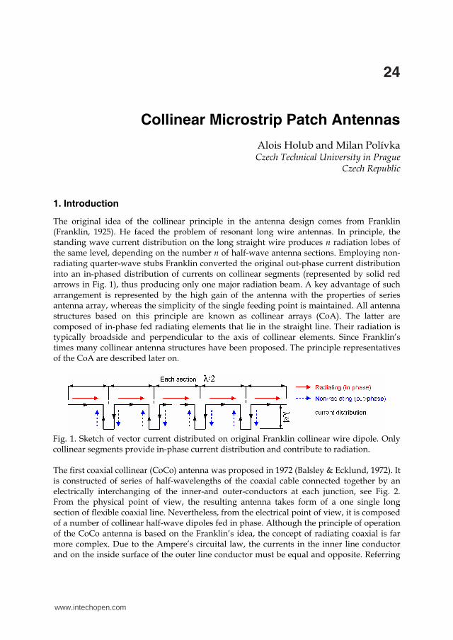
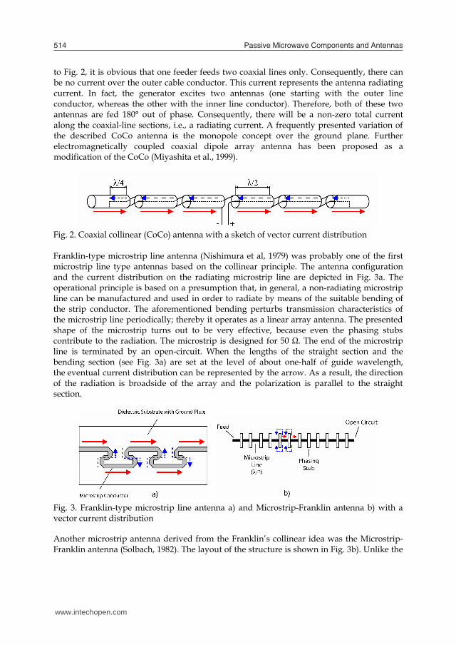
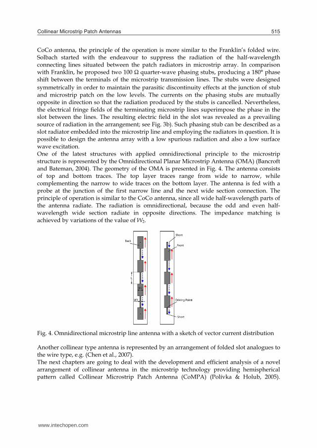
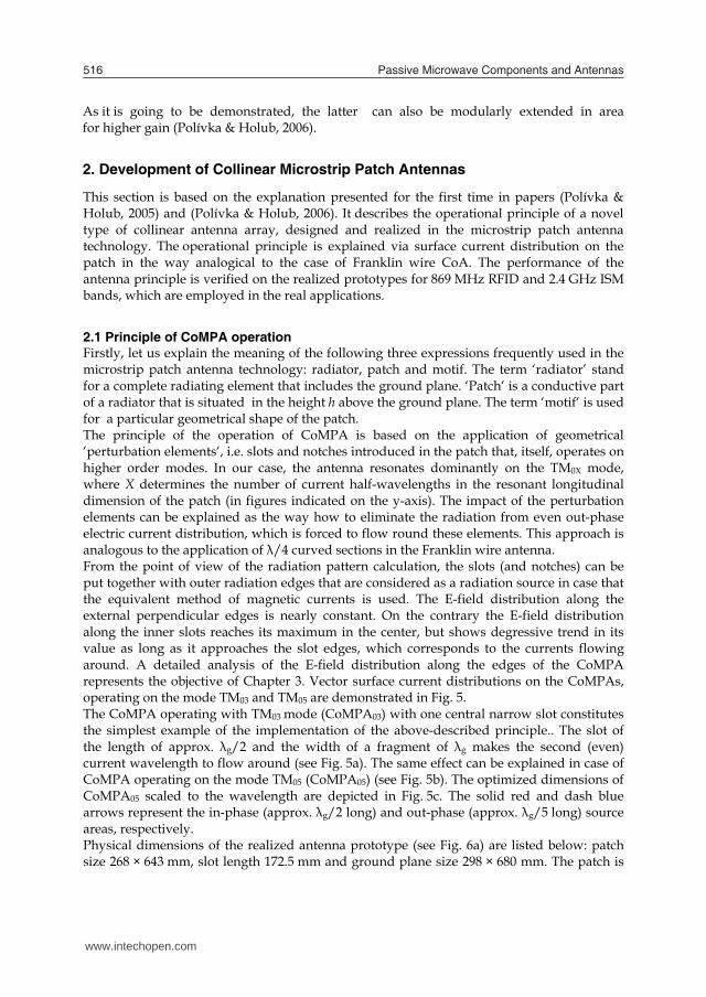
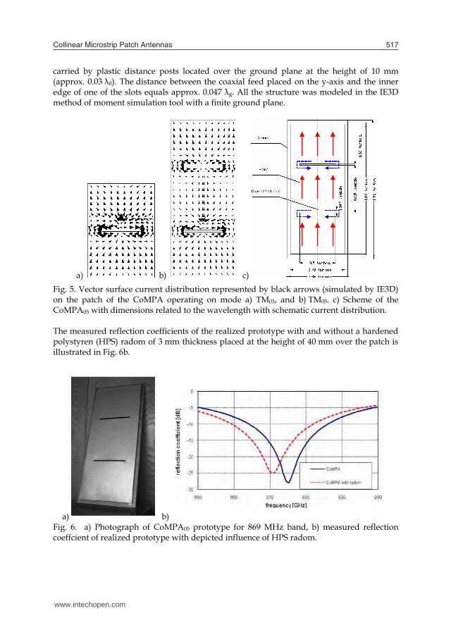
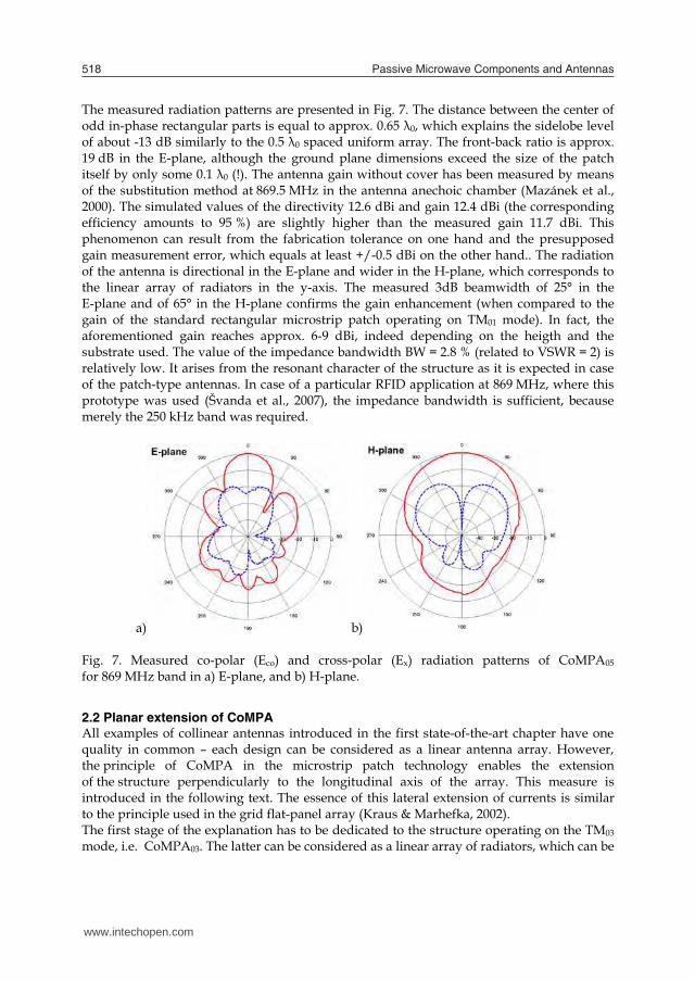
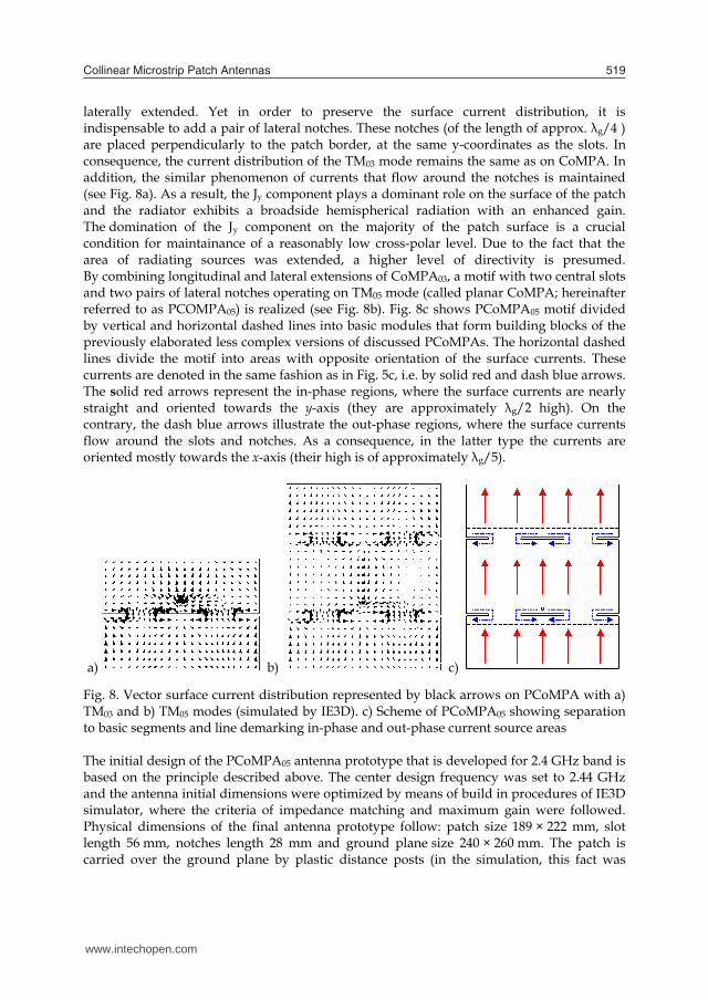
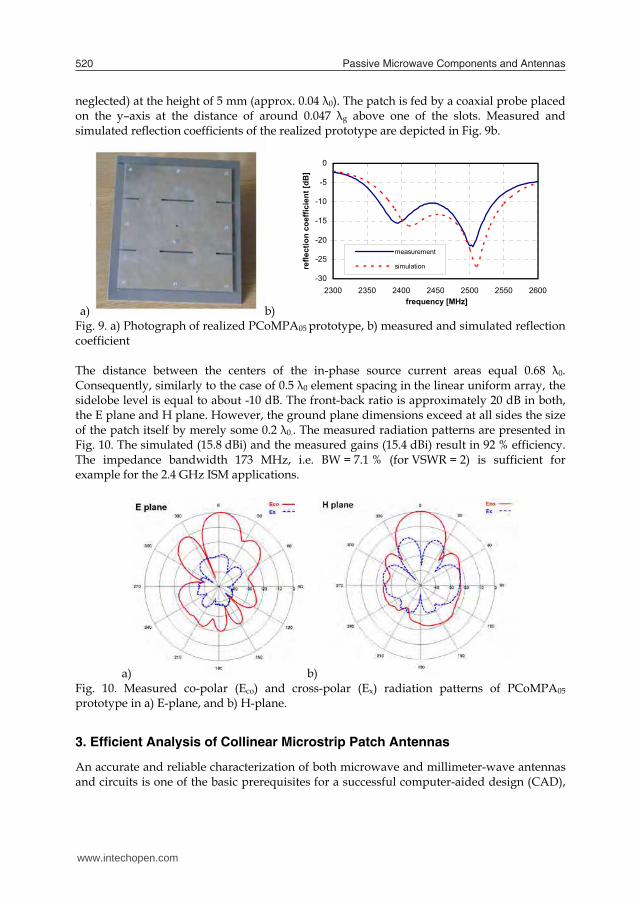
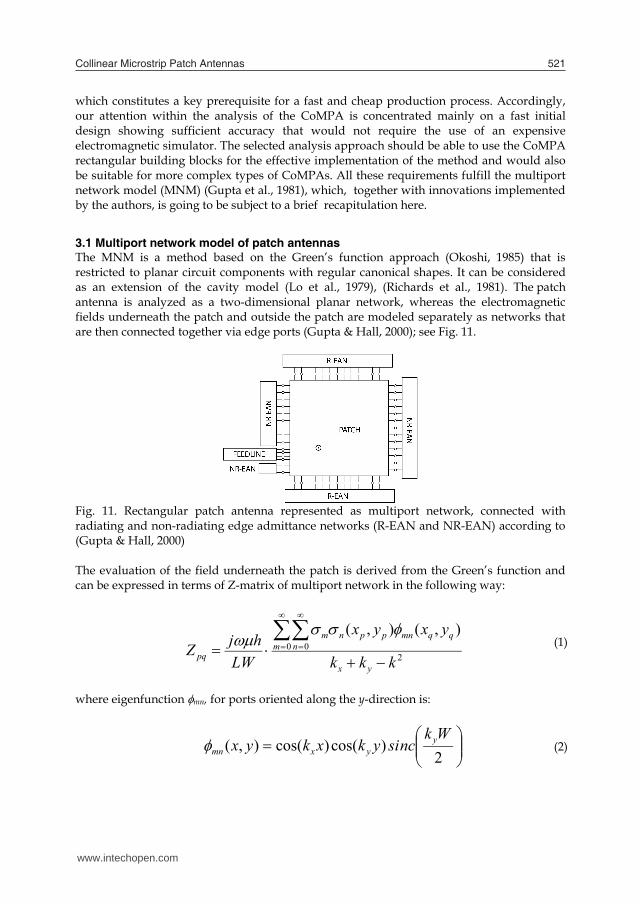
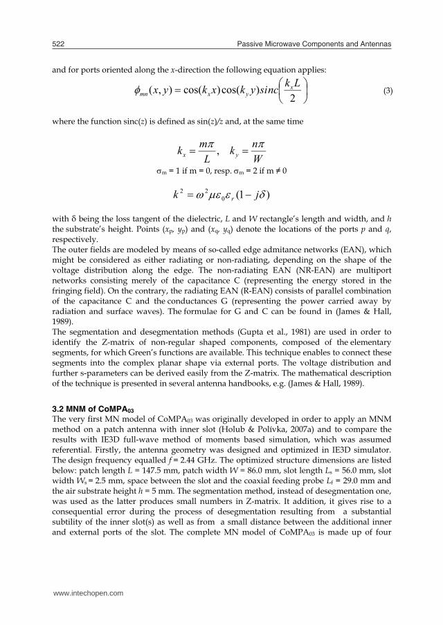
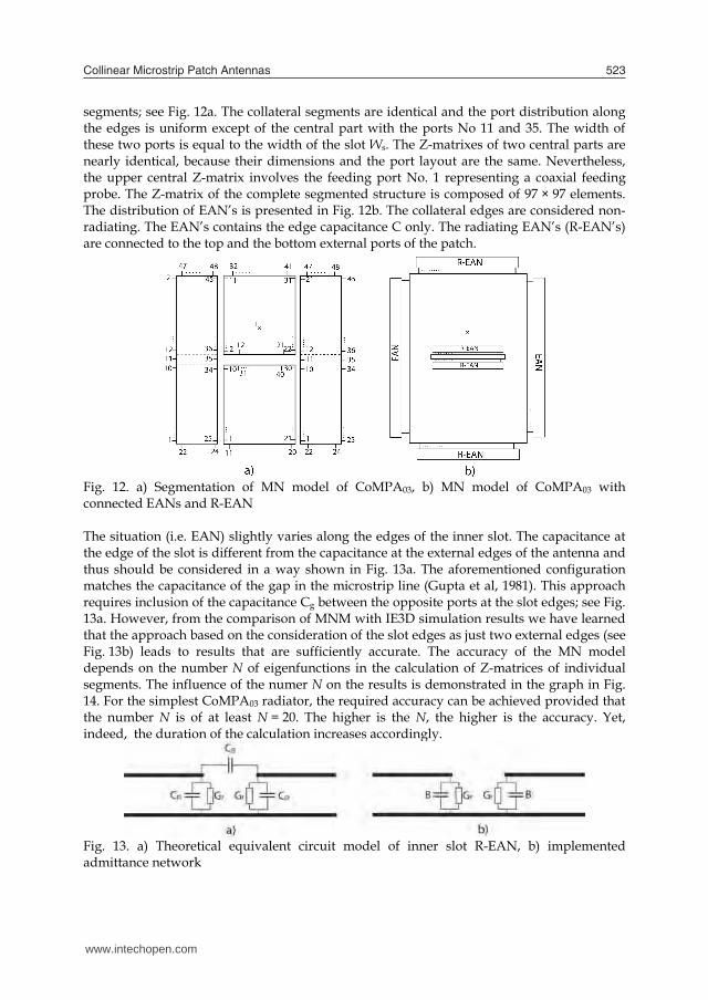
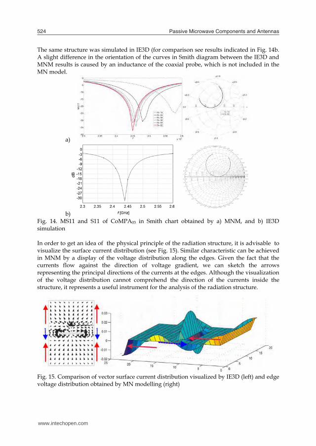
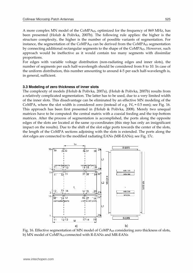
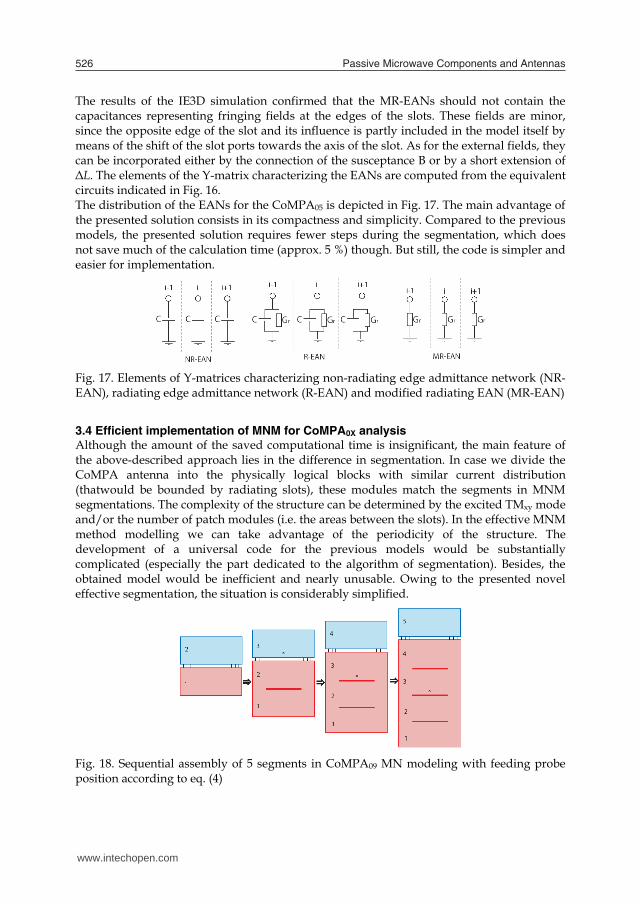
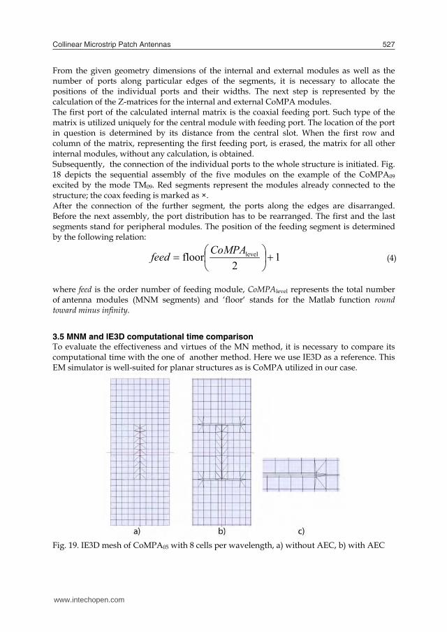
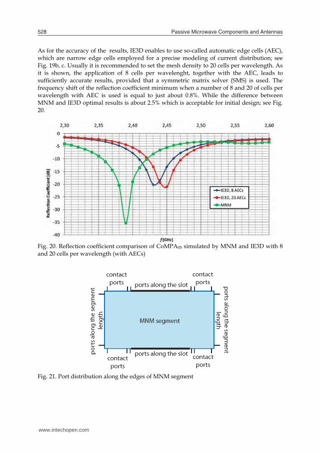
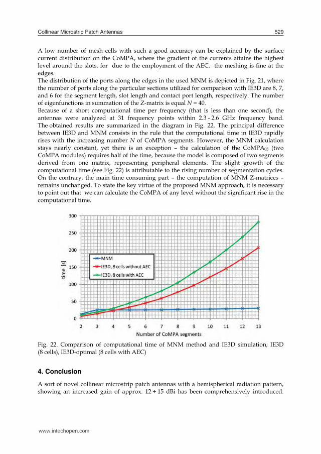


![Business cycles [Volume I] - Joseph Alois Schumpeter](https://static.documents.pub/doc/80x56/55cf8621550346484b9493ac/business-cycles-volume-i-joseph-alois-schumpeter.jpg)


