Page 1
1
Palestine Polytechnic University
College Of Information Technology and Computer Systems
Engineering
Computer System Engineering
Graduation Project Report
Alphabets Learning Game Using Video Projection Mapping
Team:
Leqa J. Daghameen & Shahd R. Salaimeh
Supervisors:
Dr. Sami Abu Snaineh
Dr.Mousa Farajallah
May 2017
Page 2
2
Dedication
To who lit the light in our road and made the sun in the darkness, to the best women in
the world, to our lovely mothers.
To who gave us hope and power to be stronger, for you: our dear fathers.
To our brothers and sisters who support us by love.
To all our friends and colleagues who encourage us to do the better.
To all of them, we dedicate this modest scientific work.
Page 3
3
Acknowledgement
First and foremost, we would like to thank Allah for giving us the strength to
complete this work. We also wish to express our sincere thanks to our supervisor, Dr.
Sami Abu-Snaineh and Dr.Mousa Farajallah. Special thanks to Eng. Mohammad Quisi,
Eng. Weal Takrouri and Mr. Basel Al-Tamimi for their helpful support.
We will never forget to thank our university that offered us the chance to prepare
this project and get BA degree.
Page 4
4
Abstract
The basis of this project was to design a game depends on two interesting
technologies, augmented reality and video projection mapping. The game will
visualize the letters and words on a box by projection mapping. Using unity three
dimensional (3D), leap motion, stepper motor and Arduino all connected with c
and c#. The aim of this project is to develop teaching and learning by increasing
the dependency on the technological tools and techniques, instead of traditional
one, also to engage students with new technologies.
Page 5
5
Contents Chapter 1: - Introduction ............................................................................................................................ 10
1.1. Overview of the Project .............................................................................................................. 10
1.2. Motivation ................................................................................................................................... 10
1.3. Importance .................................................................................................................................. 11
1.4. Goals and Objective .................................................................................................................... 11
1.5. System Description ..................................................................................................................... 12
1.6. Problem Statement ..................................................................................................................... 12
1.7. List of Requirements ................................................................................................................... 13
1.8. Expected Result ........................................................................................................................... 13
1.9.1 Previous work................................................................................................................................. 13
1.9.1.1 Differences .............................................................................................................................. 14
Chapter 2: - Background ............................................................................................................................. 15
2.1 Hardware component of the system ................................................................................................ 15
2.1.1 Leap Motion Sensor ................................................................................................................... 15
2.1.2 Arduino Uno Microcontroller..................................................................................................... 17
2.1.4 Motor Shield .............................................................................................................................. 18
2.1.5 Stepper Motor ............................................................................................................................ 18
2.1.6 Computer /laptop ...................................................................................................................... 19
2.1.7 Box.............................................................................................................................................. 19
2.1.8 USB A to B cable ......................................................................................................................... 19
2.1.9 Leap Motion Sensor Cable ......................................................................................................... 20
2.1.10 Power Supply ........................................................................................................................... 20
2.2 Design Constrains .............................................................................................................................. 20
Chapter 3:- System Design .......................................................................................................................... 21
3.1. System Design ................................................................................................................................. 21
3.1.1. Communication between the child and the Leap Motion Sensor ................................................ 21
3.1.2. Integration between the Unity-3D and the Leap Motion Sensor ................................................. 22
3.1.3. Arduino/Unity Integration: - ......................................................................................................... 23
Page 6
6
3.1.4. Connect Arduino with Stepper Motor: - ....................................................................................... 23
3.1.5. Augmented Reality Box Movement: - ........................................................................................... 24
3.1.6. Projection: - ................................................................................................................................... 24
3.2. Block diagram of the system .................................................................................................... 25
3.3. System’s Detailed Diagram ....................................................................................................... 25
3.5 System Schematic Diagram: .............................................................................................................. 28
Chapter 4: Game Design ......................................................................................................................... 30
4.1: Game Introduction ........................................................................................................................... 30
4.2: Game Elements ................................................................................................................................ 31
4.2.1: Conflict ...................................................................................................................................... 31
4.2.2: Strategy and Chance ................................................................................................................. 31
4.2.3: Aesthetics .................................................................................................................................. 31
4.2.4: Theme and story. ...................................................................................................................... 31
4.2.5: Rewards. ................................................................................................................................... 32
4.3:- Game Song and Modes ................................................................................................................... 32
4.3.1:- Leap Click Mode ....................................................................................................................... 32
4.3.2:- Mouse Click Mode ................................................................................................................... 32
4.4: - Game Levels ................................................................................................................................... 34
4.4.1: - Level 1 ..................................................................................................................................... 34
4.4.2: - Level 2 ..................................................................................................................................... 35
4.4.3: - Level 3 ..................................................................................................................................... 37
4.4.4: - Level 4 ..................................................................................................................................... 39
4.5: - flow chart of the Game .................................................................................................................. 43
Chapter 5:- Software and Hardware Implementation ................................................................................ 45
5.1 Software Implementation tools ........................................................................................................ 45
5.1.1 Unity (Game engine) .................................................................................................................. 45
5.1.2 Sketch up .................................................................................................................................... 47
5.1.3 C#-script (product name CS-Script) ............................................................................................ 47
5.1.4 Arduino Software ....................................................................................................................... 47
5.1.5 Leap Motion Driver .................................................................................................................... 48
5.1.6 Adobe Photoshop CS6 ................................................................................................................ 48
Page 7
7
5.2 Hardware Implementation tools....................................................................................................... 49
5.2.1 Leap motion sensor .................................................................................................................... 49
5.2.2 Motor Shield .............................................................................................................................. 49
5.2.3 Arduino Uno Board Implementation ......................................................................................... 50
5.2.4 Stepper Motor ............................................................................................................................ 50
5.2.5 Box Implementation .................................................................................................................. 50
Figure 27 :- 3D shaft extension ........................................................................................................... 51
5.2.6 Projector..................................................................................................................................... 52
5.2.7 Power Configuration .................................................................................................................. 52
Chapter 6:- Validation and Testing ............................................................................................................. 53
6.1 Goals Description .............................................................................................................................. 53
6.1.1 Leap Motion-Unity Test ............................................................................................................. 53
6.1.2 Arduino integration with unity Test ........................................................................................... 53
6.1.3 Stepper Motor Test .................................................................................................................... 53
6.1.4 Projector Test ............................................................................................................................. 53
6.1.5 System Test ................................................................................................................................ 53
6.2 Implementation Issues ...................................................................................................................... 54
6.2.1 Hardware Issues ......................................................................................................................... 54
6.2.2 Software Issues .......................................................................................................................... 55
Chapter 7:- Conclusion ................................................................................................................................ 57
7.1 Final results ....................................................................................................................................... 57
7.2 Extra work ......................................................................................................................................... 57
7.3 Future work ....................................................................................................................................... 61
References .................................................................................................................................................. 62
Page 8
8
List of Tables
Table 1 :- connecting the components of the system .................................................................... 27
Page 9
9
List of Figures
Figure 1 :- Leap Motion Sensor ..................................................................................................... 15
Figure 2 :- view of tracking hands for Leap Motion Sensor .......................................................... 16
Figure 3:- Leap Motion Sensor’s Interaction Box ......................................................................... 16
Figure 4:- Block Diagram of the System ........................................................................................ 25
Figure 5 :- Detailed Diagram of the System .................................................................................. 26
Figure 6 :- System Schematic diagram .......................................................................................... 29
Figure 7 :- Skip the song by using right hand ................................................................................ 30
Figure 8:- Song scene of the game ................................................................................................ 33
Figure 9:- The Scene of the beginning mode ................................................................................ 33
Figure 10:- First level of the Leap-Click Mode .............................................................................. 34
Figure 11:- First level of the Mouse-Click Mode ........................................................................... 35
Figure 12:- Second level of the Leap-Click game .......................................................................... 36
Figure 13:- Second level of the Mouse-Click game ....................................................................... 37
Figure 14:- Third level of the Leap-Click Mode ............................................................................. 38
Figure 15:- Level 3 of the Mouse-Click Mode ............................................................................... 38
Figure 16:- Level 4 of the Leap-Click Mode................................................................................... 39
Figure 17:- Level 4 of the Mouse-Click Mode ............................................................................... 40
Figure 18:- Using right or left hand in the game ........................................................................... 40
Figure 19:- Using left hand in the game ........................................................................................ 41
Figure 20:- Using both hands in the game .................................................................................... 42
Figure 21:- Flow Chart diagram of the game ............................................................................... 44
Figure 22:- Box Scene in the game ................................................................................................ 46
Figure 23:- Control interfaces of the game ................................................................................... 48
Figure 24:- Leap motion sensor with cables ................................................................................. 49
Figure 25:- LM298 motor shield.................................................................................................... 49
Figure 26:- Arduino Uno................................................................................................................ 50
Figure 27 :- 3D shaft extension ..................................................................................................... 51
Figure 28:- shaft extension design by AutoCAD ........................................................................... 51
Figure 29:- connect Arduino with Motor ...................................................................................... 54
Figure 30:- First level_ grabbing ................................................................................................... 57
Figure 31:- Second level_ grabbing ............................................................................................... 58
Figure 32:- Third level_ grabbing .................................................................................................. 58
Figure 33:- Fourth level _ grabbing ............................................................................................... 59
Figure 34:- Sample of mobile application ..................................................................................... 60
Page 10
10
Chapter 1: - Introduction
1.1. Overview of the Project
Technology plays a vital role in modern education .This is the 21st century where
technology is interconnected in every activity of life, and most importantly education. The
modern generation student can be attached with learning only when he/she finds something
interesting in it. Therefore, we must collaborate technology and learning to provide more
productive results.
In our project we will set a vision for creating learning experiences that provide the right tools
and take the benefits of technology to support both teaching and learning. We target the
primary education pupils, who need to learn alphabets and the basics of the language in a
playful and joyfully environment using projection mapping.
It is an augmented reality game! A digital game that visualizes the letters and words on a box
by projection mapping. Using unity 3D, leap motion, stepper motor, Arduino all connected
with c and c#. Leap motion which basically work like a camera that sends picture to unity 3D.
And analyzes the pictures and converts them to abstract 3-dimensional hand model. Unity
used to graph the animation, and sends signals to Arduino board. Arduino will control the
direction of the stepper motor which holds the box.
1.2. Motivation
We can use digital resources in a variety of ways to support teaching and learning
such that electronic books, digital portfolios, learning games. These tools are powerful to help
children meet the needs of modern education.
Educational games are a useful tool for building math foundation and language skills
that today's elementary school curriculum requires. These learning games are fun; the children
seem really to enjoy it and are excited about using it.
Page 11
11
Because of that, we work to enhance learning by introducing technology effectively in
our game. And make our gradation project to serve teaching and learning by developing tools
and engage children in learning.
1.3. Importance The importance of this project comes from the challenges that face primary education.
Which are the lacks of focus for children, abstract material and traditional ways of teaching.
We work to develop the tools and techniques of education to make it more suitable for
children instead of the old techniques. The advantages we gain from using technology to
educate children is to increase the students motivation and improve the way they are thinking.
This project is also important for us. it will lead us to learn some other topics that are
not included in college courses such as Projection mapping concepts, c# programming
language , working with unity 3D and how to integrate it with the hardware.
1.4. Goals and Objective
The main aim of this project is to develop the teaching and learning by increasing the
utilization of the technological tools and techniques, instead of traditional one. This will be
developed using projection mapping technology which allows us to interact with images and
videos on non-white, non-flat surface.
The objectives of this project are summarized as follows:
Build the project using Arduino micro controller.
Design the animation using unity 3D.
Use leap motion sensor to capture the hand motion.
Use stepper motor to move the box, and make the game more interactive.
Page 12
12
1.5. System Description
In this project we will design an augmented reality 3D-game for teaching children
the alphabets. The project will display images on a box via projector. The goal is to
teach the children words in a playful environment. They will be trying to find the
correct letter from set of letters and choose the correct one.
When the child moves his/her hand and fingers in the 3D space above the leap
motion sensor, it will start to track any movement and finger position. Then the
images will be sent to the PC serially using Leap motion cable in order to manipulate
it using Unity 3D.
A HDMI (video cable) will be used to connect the PC with the Projector in order
to display the game on the Box. In order to rotate the box to get a new level of the
game we will use the stepper motor which will be connected to the Arduino using
motor shield.
1.6. Problem Statement
During the preschool and kindergarten years, children learn at different rates and
with different styles. Many of the teaching methods styles are boring and non-
interesting. The main idea is to make learning for children more interactive.
In general, most of the children like games. So if we mix the games with learning
the alphabets, they will not forget what they learned. Also the game lets the children to
interact with it by choosing an object virtually and sees the result displayed on a box.
It is the best to play with letters, words and sound at an early age so that the child
will not see the learning as hard work. It is a fun educational game that the child could
do to learn the alphabet and words instead of some activities that are more difficult
and uninteresting.
Page 13
13
1.7. List of Requirements
System requirements can be summarized as:-
USB cable to integrate leap motion sensor with the PC.
Download a Core Asset package that connect leap motion sensor with PC.
To integrate Arduino with the unity by using set of commands in both c# in unity and
Arduino-c in Arduino.
An Arduino cable to connect it with PC.
Cable to connect the projector with the PC.
Motor Shield to control the Stepper Motor and integrate it with the Arduino.
White Box to display the images on it easily.
1.8. Expected Result
The project is expected to be as follow:-
The game will be developed.
The projection mapping will match with the game.
The game will be controlled with the hand and finger motion using leap motion
sensor.
The Box will be rotated based on the left hand.
1.9.1 Previous work
As we make a hard work to get an idea for the graduation project. We decided to
choose the augmented reality rotation box with projection mapping technique.
This idea came from a YouTube channel, while a young man was trying to test the
leap motion sensor; he made a simple game which took off the pet from the tree. We get
interested with the hardware, so we used it in our project with some differences.
Page 14
14
1.9.1.1 Differences
While previous work was just an application to test the leap motion sensor qualifications.
We take the idea of the hardware which is the augmented reality box and the projector. But we
combine it in our way.
As the young man used a heavy wood to make the box, we used the lightest wood –
veneer, wood – to decrease the load on the stepper motor. So we didn’t have to put a cooler and
used a smaller stepper motor to decrease the cost. Connection even differ, he used a VGA
cable to connect the projector while we used an HDMI cable to get a clear image and audio.
On the software side, we create our own game to serve learning and teaching. The
augmented reality game targets the preschool and primary education.
Page 15
15
Chapter 2: - Background
This chapter compiles and describes the hardware components used to implement
the game. It contains the design constrains also.
2.1 Hardware component of the system
2.1.1 Leap Motion Sensor
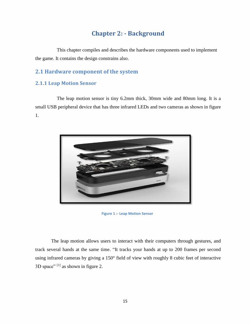
The leap motion sensor is tiny 6.2mm thick, 30mm wide and 80mm long. It is a
small USB peripheral device that has three infrared LEDs and two cameras as shown in figure
1.
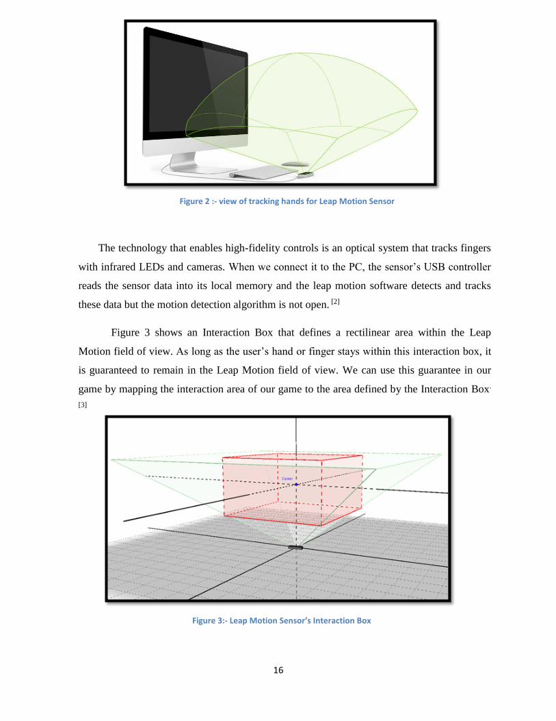
The leap motion allows users to interact with their computers through gestures, and
track several hands at the same time. “It tracks your hands at up to 200 frames per second
using infrared cameras by giving a 150° field of view with roughly 8 cubic feet of interactive
3D space” [1] as shown in figure 2.
Figure 1 :- Leap Motion Sensor
Page 16
16
The technology that enables high-fidelity controls is an optical system that tracks fingers
with infrared LEDs and cameras. When we connect it to the PC, the sensor’s USB controller
reads the sensor data into its local memory and the leap motion software detects and tracks
these data but the motion detection algorithm is not open. [2]
Figure 3 shows an Interaction Box that defines a rectilinear area within the Leap
Motion field of view. As long as the user’s hand or finger stays within this interaction box, it
is guaranteed to remain in the Leap Motion field of view. We can use this guarantee in our
game by mapping the interaction area of our game to the area defined by the Interaction Box.
[3]
Figure 2 :- view of tracking hands for Leap Motion Sensor
Figure 3:- Leap Motion Sensor’s Interaction Box
Page 17
17
Minimum system requirements for using Leap Motion Sensor: - [3]
Windows 7/8 or higher , or MAC OS X 10.7
Intel core i3/i5/i7 processor
2 GB RAM
USB 2.0 port
2.1.2 Arduino Uno Microcontroller
Microcontroller is a device that integrates a number of components including a
microprocessor into a single microchip. It is optimized to interact with other systems and
peripherals using on-board interfaces and ports.
The Arduino Uno is a microcontroller board based on the ATmega328P. It has 14 digital
input/output pins (of which 6 can be used as PWM output), 6 analog inputs, a 16 MHz
quartz oscillator, a USB connection, a power jack, an ICSP header and a reset button. It
contains everything needed to support the microcontroller, simply after connect it to a
computer with a USB cable or power it with a AC-to-DC adapter or battery, it will get started.
[4]
Arduino has the ability to connect to a variety of sensors and peripherals. It can receive
and exchange data with these peripheral. The microcontroller on the board can be
programmed using the Arduino programming language (based on wiring) and the Arduino
development environment (based on Processing). Arduino projects can be stand –alone or
they can communicate with the software that is running on a computer.
We have chosen the Arduino Uno microcontroller for this project in order to fit on with
the Motor Shield as both have the same size.
Page 18
18
2.1.3 Projector
A projector is an optical device that projects an image (or moving images) onto a surface.
It is designed to receive a video signal from some external device-usually a DVD player, a
Blu-Ray player, or a computer-and project that signal onto a screen. It does this by displaying
the image represented in the video signal onto a small screen inside the projector itself, which
is then projected onto a screen using a bright light and a lens. The lens is a piece of glass
shaped in a very specific way designed to take the small image and turn it into a dramatically
larger one. Projectors allow users to alter a variety of image features, including brightness,
sharpness and color settings, in the same way a standard television would. [5]
2.1.4 Motor Shield The Arduino Motor Shield is a dual full-bridge driver designed to drive inductive
loads such as relays, solenoids, DC and stepping motors. It lets you drive two DC motors with
your Arduino board, controlling the speed and direction of each one independently. You can
also measure the motor current absorption of each motor, among other features.
The Arduino Motor Shield can be powered by an external power supply; the IC mounted
on the shield has two separate power connections, one for the logic and one for the motor
supply driver. The required motor current often exceeds the maximum USB current rating.
External (non-USB) power can come either from an AC-to-DC adapter or battery. The
adapter can be connected by plugging a 2.1mm center-positive plug into the Arduino's board
power jack on which the motor shield is mounted or by connecting the wires that lead the
power supply to the Vin and GND screw terminals, taking care to respect the polarities. [6]
2.1.5 Stepper Motor A stepper motor is an electromechanical device which converts electrical pulses into
discrete mechanical movements. The shaft or spindle of a stepper motor rotates in discrete
step increments when electrical command pulses are applied to it in the proper sequence. The
motors rotation has several direct relationships to these applied input pulses. The sequence of
the applied pulses is directly related to the direction of motor shafts rotation. The speed of the
Page 19
19
motor shafts rotation is directly related to the frequency of the input pulses and the length of
rotation is directly related to the number of input pulses applied [7]
2.1.6 Computer /laptop We need a PC that has the following properties: -
At least 2 USB ports, one to connect PC with the Leap Motion Sensor and the other to
connect PC with the Arduino.
HDMI port to connect PC with Projector or VGA convertor.
Need at least 2GB RAM.
Intel i3 or i5 or i7 processor because of using the Leap motion sensor.
2.1.7 Box The box that we will need in our project is a 40*40*40 veneer white cube .a 40 cm
length is very suitable to integrate with the projector.
Why not on the wall or white board? Because we use a new technology that called a
projection mapping! We need the 3d animation to look nearly 3 dimensional and real.
Projection mapping is to present light on nonwhite and non flat surface, so when the cube
rotates it will integrate with the unity 3d to show a new level of the game
2.1.8 USB A to B cable This is the most common A to B Male/Male type peripheral cable. It is used to connect
a host device (Computer) to a peripheral (Microcontroller). The type ‘A’ connector is a
flattened rectangle that plugs into the USB host. The ‘B’ connector is a square with two
beveled corners, which plugs into peripheral. It is compatible with most USB boards like USB
Arduino boards. It transfers data at speed up to 480Mbit/s. [8]
Arduino use the USB port to simulate a serial port, so we have to use a USB cable to
connect the Arduino USB port to computer USB port.
Page 20
20
2.1.9 Leap Motion Sensor Cable
It is used to connect a host device (computer) to the leap motion. One the side is a
flattened rectangle that plugs into the USB host. The other one looks like a mini and micro next
to each other, which plugs into the Leap Motion Sensor.
2.1.10 Power Supply A power supply is an electronic device that supplies electric energy to an electrical
load. The primary function of a power supply is to convert one form of electrical energy to
another and, as a result, power supplies are sometimes referred to as electric power
converters. Some power supplies are discrete, stand-alone devices, whereas others are built
into larger devices along with their loads.
Power supplies have a power input, which receives energy from the energy source, and
a power output that delivers energy to the load. In most power supplies the power input and
output consist of electrical connectors or hardwired circuit connections, though some power
supplies employ wireless energy transfer in lieu of galvanic connections for the power input
or output. Some power supplies have other types of inputs and outputs as well, for functions
such as external monitoring and control.
2.2 Design Constrains
Lack knowledge in augmented reality and video projection mapping.
Little background in c# that we will use in game programming.
The available budget.
Time taken to develop the system.
Mechanical concepts.
Page 21
21
Chapter 3:- System Design
This chapter contains the design details of the system. It also contains a block and
detailed diagram of the system integration.
3.1. System Design
3.1.1. Communication between the child and the Leap Motion Sensor
when the child moves his/her hands and fingers in the space above the sensor, the sensor
will start to track any movement and finger pointing using the cameras inside the sensor. This
means it will provide a real time tracking of hands and fingers in three-dimensional space.
The camera takes the images of the hands and fingers movement and sends them to an IC
located inside the sensor. This IC will send these images serially to the Unity 3D via USB in
order to process and analyze it.
In our game there are four different hand’s commands that can be summarized as follows:-
1. Right or left hand to choose the object.
2. The left hand to move the box.
3. Both right and left hand to restart the game.
4. Right hand only to skip the alphabet song.
We selected Leap Motion Sensor because of the following reasons:-
Portable; because of its small size.
It is better suited for PC games.
Affordable and inexpensive.
Doesn’t require the use of graphical processing unit because it depends on the infrared camera
and the SDK.
Page 22
22
3.1.2. Integration between the Unity-3D and the Leap Motion Sensor
The captured images (Frames) from the Leap motion will be processed by the assets
SDK. The assets SDK package comes with the leap motion, and it provides functions to
access and process the images.
To integrate the leap motion with the unity 3D we will follow the steps below:-
1. Download the leap motion asset package that includes plugin files for using the leap
motion sensor on windows computer. This package connects the reality of the hands with
the Virtuality of the output of the sensor. So we will import the leap motion asset package
into the Unity project.
2. Download the models of leap motion. These models contain the features that we need to
use for our game. Then we will import them to the Unity application. In our
implementation we will use two types of these models:-
a. Hand models: - The leap motion software uses an internal model of a human hand to
provide predictive tracking even when parts of the hands are not visible. Although
tracking is optimal when the silhouette of a hand and all its fingers are clearly visible.
The software uses the visible parts of the hand, and previous observations to calculate
the most likely positions of the parts that are not currently visible. More than two
hands can appear in the hand list if more than one person’s hands, we recommend
keeping at most two hands in the leap motion sensor’s field of view for optimal
motion tracking quality.
b. Fingers models: - leap motion software provides information about each finger on the
hand. If all or part of a finger is not visible, the finger characteristics are estimated
based on recent observations and the model of the hand. Fingers are identified by
name such as thumb, index, middle, ring and pinky.
Page 23
23
3.1.3. Arduino/Unity Integration: - The communication between Arduino and the computer is mediated using the serial
port. We will use it to exchange messages with Unity.
First of all we want to configure the serial port on unity using serial port class and the full
.NET 2.0 libraries. Arduino does not come with a sophisticated library for the serial port, so
we can use the ports without complexity.
In unity, to initialize the serial port in C#, we need its port name and baud rate (speed).
While the baud rate is determined by the Arduino code. It is automatically assigned by the
OS depending on which device and port that is used.
In Arduino, serial command library allows to specify commands that can be received on
the serial port. The baud rate is used to initialize the serial port. This value must match the one
used in C# script in unity 3D.
In our project we will program a c# script to control the stepper motor directions using
Arduino.
3.1.4. Connect Arduino with Stepper Motor: -
Stepper motor is a DC motor that moves in discrete steps, it has multiple coils that are
organized in groups called "phases". By energizing each phase in sequence, the motor will
rotate one step at a time. This gives a total control over the motor, allowing moving it in
accurate speed.
With a computer controlled stepping we will achieve very precise positioning and speed
control. We will connect stepper motor to Arduino by Arduino Motor Shield to overcome the
complexity. It makes it very simple to incorporate a motor, and easily control motor direction
and speed using an Arduino. By simply address Arduino pins. It also allows you to be able to
power a motor with a separate power supply of up to 12v.
Page 24
24
In software, we will use Arduino IDE environment and stepper library to control the
movement of the motor.
3.1.5. Augmented Reality Box Movement: - In our project we use a white wooden 40*40*40 cm box that will be rotated by the
stepper motor according to the player hand motion. The box will provide augmentation to the
game. The unity animation will be shown on it, so the player can interact with it.
3.1.6. Projection: -
Projection mapping can work with any projector. It depends on how bright we want the
image to be. It is recommended to use ‘short-throw’ projectors so it is possible to position a
projector much closer to the display surface.
We will use the projector in our game to visual animation. The child will see the alphabets on
the box, and use his/her hands to control it and play the all levels of the game.
Page 25
25
3.2. Block diagram of the system
In the block diagram in figure 3 below, we show the system's main components. The arrows
and lines represent the connections and data flow among different parts.
3.3. System’s Detailed Diagram
When the child moves his/her hand and fingers in the 3D space above the leap motion
sensor, it will start to track any movement and finger position. Then the images will be sent to
the PC serially using Leap motion cable in order to manipulate it using Unity 3D.
A HDMI (video cable) is used to connect the PC with the Projector in order to display the
game on the Box. In order to rotate the box to get a new level of the game we will use the
stepper motor which will be connected to the Arduino using motor shield.
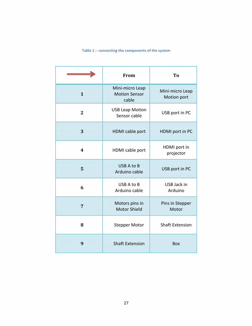
Table 1 below shows how exactly connects the components with each other.
Figure 4:- Block Diagram of the System
Page 26
26
Figure 5 :- Detailed Diagram of the System
2
1
2
1
4
4
5
3 3
6
6
7
7
Arduino Uno
Leap motion sensor
Stepper Motor
Box
Projector
Laptop HDMI Cable
5
9 9
8
8
Motor-Shield
Page 27
27
Table 1 :- connecting the components of the system
From To
1 Mini-micro Leap Motion Sensor
cable
Mini-micro Leap Motion port
2 USB Leap Motion
Sensor cable USB port in PC
3 HDMI cable port HDMI port in PC
4 HDMI cable port HDMI port in
projector
5 USB A to B
Arduino cable USB port in PC
6 USB A to B
Arduino cable USB Jack in
Arduino
7 Motors pins in Motor Shield
Pins in Stepper Motor
8 Stepper Motor Shaft Extension
9 Shaft Extension Box
Page 28
28
3.5 System Schematic Diagram: The schematic diagram represents the elements of the system, and the pins connections of
every element.
Arduino will be connected with the motor shield to overcome the complexity. The motor
shield will be connected with the stepper motor, which supposed to carry the augmented reality
box.
Pc will be the core device that connects the parts with each other. Pc connected with
projector with HDMI cable, and connected with the leap motion with mini-micro USB cable,
also with USB A to B cable with Arduino.
Page 29
29
Figure 6 :- System Schematic diagram
Page 30
30
Chapter 4: Game Design
4.1: Game Introduction The beginning of the game will be an alphabet song. The song must contain the capital
and small letters, also a picture of any object for each letter start with that letter, for example
“Apple” for letter “Aa”, “Cat” for letter “Cc” and so on. By using the HDMI Cable from PC
to the Projector, it will provide a sound effect easily.
The children who know the alphabets can skip this song by using their right hand, and
they can start the game as shown in figure 7 below. However who doesn’t know the alphabets
should listen to the whole song and then the game will be started.
Figure 7 :- Skip the song by using right hand
Page 31
31
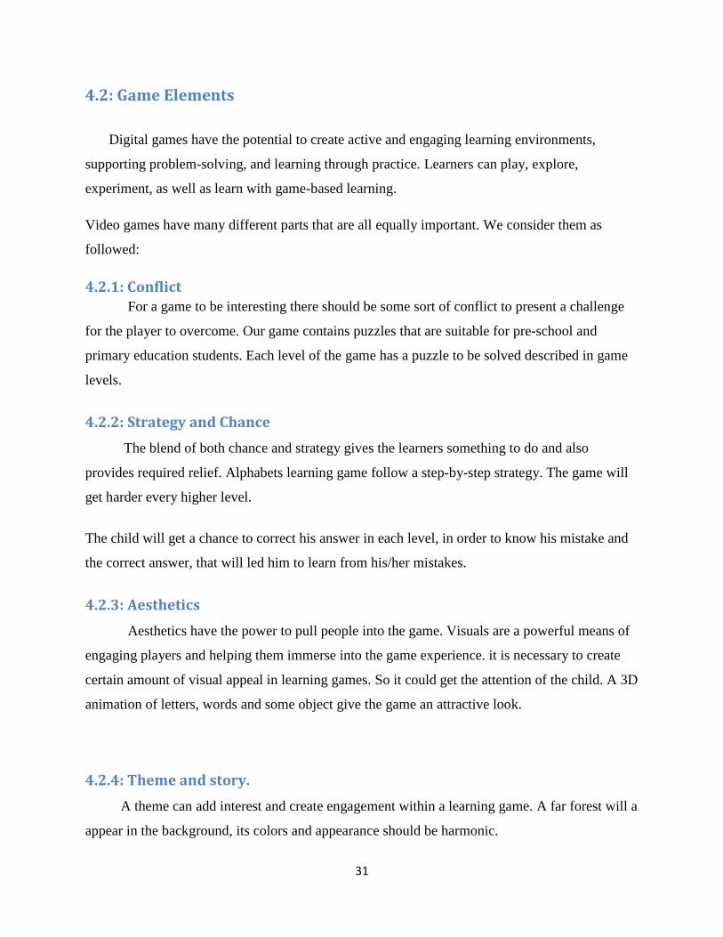
4.2: Game Elements
Digital games have the potential to create active and engaging learning environments,
supporting problem-solving, and learning through practice. Learners can play, explore,
experiment, as well as learn with game-based learning.
Video games have many different parts that are all equally important. We consider them as
followed:
4.2.1: Conflict For a game to be interesting there should be some sort of conflict to present a challenge
for the player to overcome. Our game contains puzzles that are suitable for pre-school and
primary education students. Each level of the game has a puzzle to be solved described in game
levels.
4.2.2: Strategy and Chance
The blend of both chance and strategy gives the learners something to do and also
provides required relief. Alphabets learning game follow a step-by-step strategy. The game will
get harder every higher level.
The child will get a chance to correct his answer in each level, in order to know his mistake and
the correct answer, that will led him to learn from his/her mistakes.
4.2.3: Aesthetics
Aesthetics have the power to pull people into the game. Visuals are a powerful means of
engaging players and helping them immerse into the game experience. it is necessary to create
certain amount of visual appeal in learning games. So it could get the attention of the child. A 3D
animation of letters, words and some object give the game an attractive look.
4.2.4: Theme and story.
A theme can add interest and create engagement within a learning game. A far forest will a
appear in the background, its colors and appearance should be harmonic.
Page 32
32
Each level of the game has its own characteristics, solving puzzles or matching pictures with
words will be the considered.
4.2.5: Rewards.
Rewards are things that players earn through game play. In our game, we give the player
achievements for accomplishing certain tasks. The child will earn score (star) for each correct
answer, until he/she finished all the levels of the game.
4.3:- Game Song and Modes
The start point of a game will be a song as shown in the Figure 8 below. After the song is
completed, the player can choose one of the two modes described as follows:-
4.3.1:- Leap Click Mode
This mode allows the child to choose the correct answer by clicking on the object by
using his/her hand virtually.
4.3.2:- Mouse Click Mode
Mouse mode allows the children who didn’t like the first mode or can’t use it, to interact
with our game by simply clicking on the correct answer by using mouse.
After the player choose one of the modes, the chosen mode will be loaded to start the
game depends on what the player chooses. The scenes of the beginning modes are shown
in the Figure 9.
Page 33
33
Figure 8:- Song scene of the game
Figure 9:- The Scene of the beginning mode
Page 34
34
4.4: - Game Levels The game contains of four levels described as follows:-
4.4.1: - Level 1 The first level starts after the song finished for beginners, and those who familiar in
alphabetical, the game will start after they skipped the song. In this level, the player will
match the capital letter to its small case by choosing the correct. This level will consist of 5
scenes. After the player finished this level, he will get five points (stars), and then the game
will turn into a new level.
Figure 10 shows all the scenes of the first level-Leap Click Mode, while Figure 11
shows all the scenes of Mouse Click Mode.
Figure 10:- First level of the Leap-Click Mode
Page 35
35
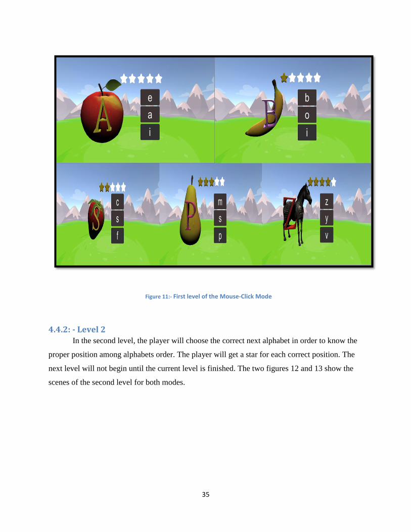
Figure 11:- First level of the Mouse-Click Mode
4.4.2: - Level 2 In the second level, the player will choose the correct next alphabet in order to know the
proper position among alphabets order. The player will get a star for each correct position. The
next level will not begin until the current level is finished. The two figures 12 and 13 show the
scenes of the second level for both modes.
Page 36
36
Figure 12:- Second level of the Leap-Click game
Page 37
37
Figure 13:- Second level of the Mouse-Click game
4.4.3: - Level 3
The third level will be a word-picture matching, the player will click on the correct
word that represents the object. If the player finished this level, the score will be four stars,
and the last level will start. Otherwise, the new level won’t start. in the figure 14 and Figure
15 shows the whole scenes for both modes.
Page 38
38
Figure 14:- Third level of the Leap-Click Mode
Figure 15:- Level 3 of the Mouse-Click Mode
Page 39
39
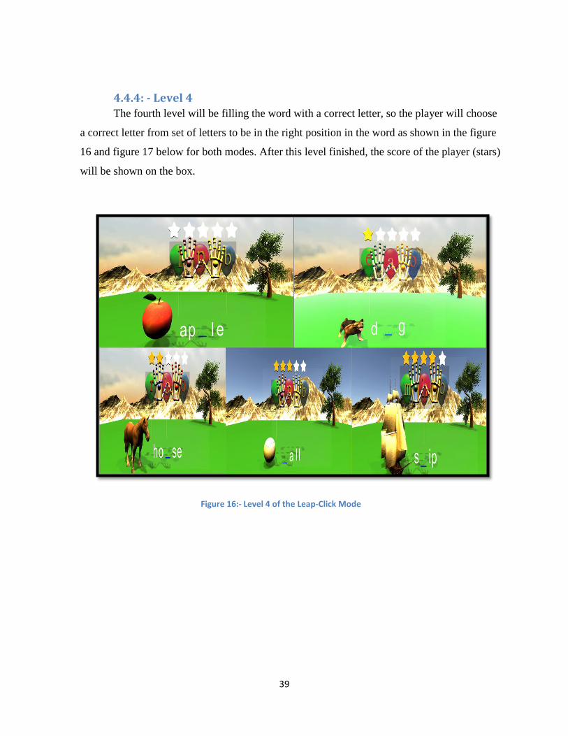
4.4.4: - Level 4 The fourth level will be filling the word with a correct letter, so the player will choose
a correct letter from set of letters to be in the right position in the word as shown in the figure
16 and figure 17 below for both modes. After this level finished, the score of the player (stars)
will be shown on the box.
Figure 16:- Level 4 of the Leap-Click Mode
Page 40
40
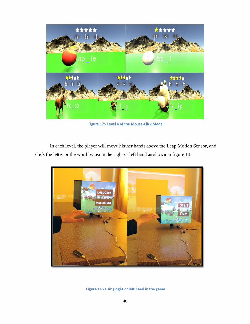
Figure 17:- Level 4 of the Mouse-Click Mode
In each level, the player will move his/her hands above the Leap Motion Sensor, and
click the letter or the word by using the right or left hand as shown in figure 18.
Figure 18:- Using right or left hand in the game
Page 41
41
At the end of each level, the player will move to the next level by using the left hand
as shown in figure 19.
Figure 19:- Using left hand in the game
Page 42
42
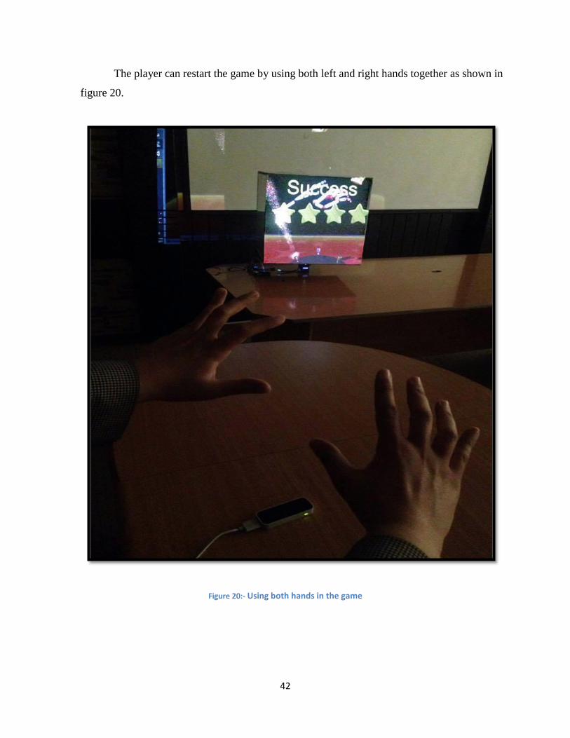
The player can restart the game by using both left and right hands together as shown in
figure 20.
Figure 20:- Using both hands in the game
Page 43
43
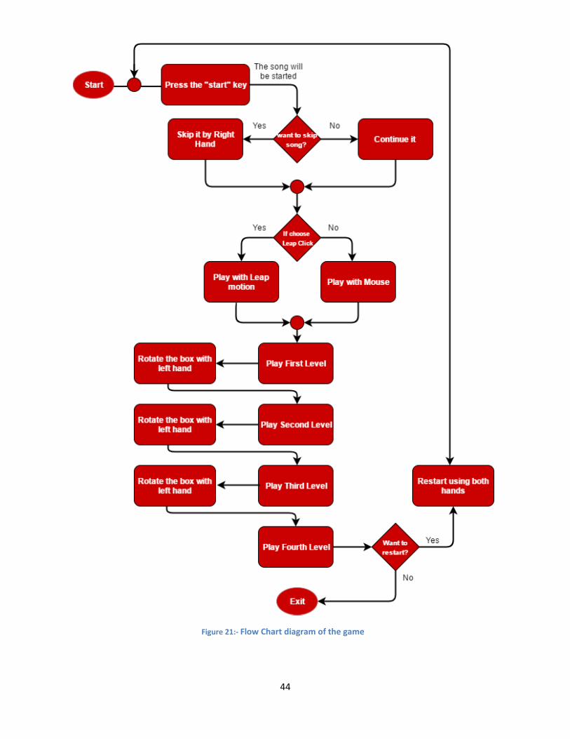
4.5: - flow chart of the Game In the diagram in figure 21 below, we show the game’s structure. It consists of four
levels. The children, who familiar in the alphabetical can skip the Alphabet song, then choose
which mode he/she wants to play with. Each mode selected will go to the first level.
Switching between levels can be done by using left hand. After the last level finished, the
player can restart the game and back to the alphabet song.
Page 44
44
Figure 21:- Flow Chart diagram of the game
Page 45
45
Chapter 5:- Software and Hardware Implementation This chapter describes the implementation of software that used in our project, such as
the programs and the IDEs used to build the project codes and the set of tools and packages that
helped us. Also the hardware components.
5.1 Software Implementation tools
This section provides some information regarding to the main programs and software
technologies used in the project:
5.1.1 Unity (Game engine) Unity is a flexible and powerful cross-platform game engine for creating
multiplatform3D and 2D games for PC, consoles, mobile devices and websites.
It used to build the 3D environment for our game. The game consists of 50 scenes (user
interfaces). The first scene is the "home scene", which composed of control buttons and the user
must choose an action by clicking on one of these buttons. The home scene consists of two
buttons which are labeled "Start” and "Exit". If the user clicks on the first button, the control will
be passed to the next scene which is the "beginning song" game scene, after the song finished the
select mode screen will appear, and the player can feel free to choose any one of them. By
choosing anyone of the modes, the first level will start, and a group of stars will be shown to
inform that the level has stars-number section. The child will continue playing until he/she gains
all the stars, then the child can move to the higher level.
"Close" button, will exit the game in case the child decided to.
All of the 3D letters that appears in our level designed by us, and the other 3D objects
imported from unity assets store. At the end of each level the box scene will appear to prepare
the user to the higher level as shown in the figure 22.
Page 46
46
Figure 22:- Box Scene in the game
5.1.1.1 First Level description: The first level consists of five scenes; every scene contains three cases, and one
3D object. The player should choose one of the letters that represent the small form of the
capital one. If the player chooses the false answer, a (X) mark will appear. Otherwise,
he/she will earn a star and moves to the next scene at the same level.
5.1.1.2 Second Level description: Second level consists of two scenes; every scene contains two cases, and one 3D
object. The player should choose one of the letters that will come after the last
pronounced letter. If the player chooses the false answer, a (X) mark will appear.
Otherwise, he/she will earn a star and moves to the next scene at the same level.
5.1.1.3 Third Level description: Third level consists of four scenes; every scene contains three words, and one 3D
object. The player should choose the word that represents the object. If the player chooses
the false answer, a (X) mark will appear. Otherwise he/she will earn a star and moves to
the next scene at the same level.
Page 47
47
5.1.1.4 Fourth Level description: The last level will consist of five scenes; every scene contains three letters, and
one 3D object. The child have to choose the missed letter to form a correct word, if the
player chooses the false answer, a (X) mark will appear. Otherwise he/she will earn a star
and moves to the next scene at the same level.
5.1.2 Sketch up Sketch Up is a friendly and error-prone 3D modeling software. It does not sacrifice user-
friendliness for the sake of functionality. Easily create complex, beautiful, high-quality artwork
shapes from start to finish.
In our project, we basically used sketch up to create 3D letters, and then paint surfaces with
probability method.
5.1.3 C#-script (product name CS-Script)
The behavior of game objects is controlled by the components that are attached to them.
Unity allows developers to create these components or what so-called "scripts" using C#-Script,
JavaScript. We decided to use C#-script because it is the most scripting tool used across the three
offered by unity. C#-script defines a blueprint for the unity objects and so none of its code will
be activated until an instance of the script is attached to them. This allowed us to trigger game
events, modify component properties over time and respond to user input in our game. We used
Microsoft Visual Studio 10 IDE to create the needed C#-script codes in our project.
5.1.4 Arduino Software The open-source Arduino Software (IDE) provides a way to write codes and upload it to
the board. It is compatible with Windows, Mac OS X, and Linux. The environment is written in
Java and based on Processing and other open-source software. This software can be used with
any Arduino board. But we chose the Arduino Uno board because its functionality and bins are
enough and suitable for our target.
We used the stepper library to control the speed and direction of nema17 stepper motor.
This program should be connected with unity to synchronize the virtual box movement with the
real one.
Page 48
48
5.1.5 Leap Motion Driver
Leap motion driver which called Orion software represents a paradigm shift in hand
tracking. It’s built specifically for VR. It’s radically smoother, faster, and more reliable. It
enables players to quickly, effectively interact with games.
5.1.6 Adobe Photoshop CS6
An image editing software developed and manufactured by Adobe Systems Inc.
Photoshop is considered as one of the leaders in photo editing software. The software allows
users to manipulate, crop, resize, and correct color on digital photos.
We used the adobe Photoshop software to design the control interfaces of the game, as shown in
the figure 23.
Figure 23:- Control interfaces of the game
Page 49
49
5.2 Hardware Implementation tools
This section provides some information about the hardware implementations done in our
project:
5.2.1 Leap motion sensor
This device is the main controller of all the system. When the hand/s appears/s on
the leap visualizer we can say that they are in the interaction area and we can translate its
movement.
5.2.2 Motor Shield
As we mentioned in chapter two, we used LM298 Motor Drive Shield, in order to control
Stepper Motor speed and direction. It has been connected to the Arduino Uno pins 8-11.
Figure 24:- Leap motion sensor with cables
Figure 25:- LM298 motor shield
Page 50
50
5.2.3 Arduino Uno Board Implementation
We used Arduino Uno board to control the movement of the box. The child will
put his/her left hand above the interaction area of the leap motion. Leap motion sensor
will translate this action as a variable, so when the left hand appears the augmented realty
box will rotate 90 degree.
5.2.4 Stepper Motor
Choosing Nema 17 stepper motor based on calculation for required torque, it has the
following specifications:
200 steps per revolution, 1.8 degrees
Coil #1: Red & Yellow wire pair. Coil #2 Green & Brown.
Bipolar stepper, requires 2 full H-bridges
4-wire, 8 inch leads
12V rated voltage (can drive it at a lower voltage, but the torque will drop) at
350mA max current.
5.2.5 Box Implementation
We prepared the box to fit with the virtual box inside the game. We centered the
base of the box in order to put the stepper motor, so we used shaft extension, and we
designed it to hold the box base as shown in the figures 27 and 28 below.
Figure 26:- Arduino Uno
Page 51
51
Figure 27 :- 3D shaft extension
Figure 28:- shaft extension design by AutoCAD
Page 52
52
5.2.6 Projector
The main goal of using the projector is to mapping our game from PC to the box.
So we tried a many strategies to achieve that goal.
5.2.7 Power Configuration
The whole system needs power to run all its components to get the wanted result.
A 5-12V needed to power the Arduino and Motor shield. At the beginning we have used
the power supply device, and then after we get the suitable voltage and amber we used a
power adapter instead to make the project portable
Page 53
53
Chapter 6:- Validation and Testing
This chapter shows and explains the results of the implementation of the system of our project.
6.1 Goals Description
Since the project’s system consists of five main tasks, each task was implemented and tested
individually; after debugging and obtaining successful results from each, the five were all
combined together. The five main tasks are described as follows:-
6.1.1 Leap Motion-Unity Test
We choose unity 5.4.0 because it’s compatible with the leap motion assets, after
importing alphabets objects and other game objects, we build the environments, and
design several scenes, then we tested it using leap motion sensor, depending on the sensor
packages that expedite the work.
6.1.2 Arduino integration with unity Test
After running the game and supply motor with power, integration was tested and
both of unity virtual box and the actual box moved at the same time with suitable values
for rotations and speed.
6.1.3 Stepper Motor Test
Motor used to rotate the real box, so when the power supply was applied to the
motors, the arduino code was run and made box rotate.
6.1.4 Projector Test
Projector used to achieve the game mapping from PC to the Box, we tested the
mapping using HDMI cable.
6.1.5 System Test
The whole system works well, the game is well designed and the augmented
realty box rotates. Projector projects in a fine resolution and the sounds are clear and
hearable because of the HDMI connection.
Page 54
54
Software and hardware gathering in the right way to form Alphabets learning
game using projection mapping.
Figure 29 below, shows how we connect Arduino with stepper motor through the
shield. We connected the pins IN1, IN2, IN3, IN4 from the motor shield with the 8, 9,
10, 11 digital pins of Arduino board respectively. The pins OUT (1, 2, 3, and 4) on the
motor driver connected with the Stepper motor as following Coil #1: black wire (A+)
with Out1 & green wire(A-) with Out2. Coil #2: Red wire (B+) with Out3 & blue wire
(B-) with Out4.
Figure 29:- connect Arduino with Motor
6.2 Implementation Issues
6.2.1 Hardware Issues
Scarcity of mechanical information:
Skill shortage in mechanical makes the project seems harder. Stepper suitable rotation
and speed take around month to be ready. Mechanical department in Palestine
Polytechnic University helped to study more about stepper motor and its characteristics.
Page 55
55
Stepper motor selection:
stepper motor calculations were made in order to design the system. The idea was to
suppose that the box has two boxes, the outer box which has 400 gm weight, and the
inner box which is filling of air. This design failed because the calculation was for a solid
cube.
a deep search is made to obtain the final results. The weight of the box is very light so the
choice of the stepper motor can be known experimentally.
Finally, a simple equation is calculated to find the torque according to the box weight and
safety factor to decrease the motor heating.
Motor Driver selection:
At first BL-TB6560-V2.0 motor driver is used, It supposed to be compatible with the
chosen stepper motor [nema17], it has complex functionality and different modes .the
result was a damage in the motor driver and the Arduino Uno.
Another research is made to find more simple and compatible motor drive. LM298 Motor
Drive Shield Module was chosen to run the nema17 stepper motor. It gives the desired
speed and direction.
Video projection mapping problem:
video projection mapping is considered as a major issue. The problem of displaying the
game on the box and applying video projection requires a fixed position projector and a
wide space for projection.
6.2.2 Software Issues
Our laptops aren’t suitable for design and development the games.
Leap motion Orion software and assets are beta versions. Because of this problem our
project closed suddenly and when we tried to open, we didn’t find any scenes.
High resolution 3D unity objects have a high cost.
Page 56
56
The most trouble issue we faced is that the packages of the leap motion sensor are not
compatible with each other, while we tried to mix the new version with the older one; a
lot of problems is produced in namespace and packages issues. The older one supports
the grabbing of the objects, and the new version supports the user interface (GUI). So we
changed the idea to clicking on the buttons, because of the next issue.
The next issue is about grabbing, while the package doesn’t supports distingue objects,
we moved to a clicking one. As we asked for this problem in the unity forum, no one
replied to us. [9].
As our project title described the projection mapping, so we need a package to use with
unity and make our game projected correctly. But that package was too expensive, it
costs 500$. We solved it by depending on the stencil package that support producing a
cut design of the surfaces.
Our project depends on the new technologies which are Leap motion and projection
mapping. And all of the software problems we faced need a deeper specialist in order to
help us.
Page 57
57
Chapter 7:- Conclusion This chapter concludes final results, extra work and will propose future works that can be
developed on the system.
7.1 Final results
The system integrated using unity and Arduino IDE. It consisted of two parts, the unity
game which was developed using 5.4.0. The alphabets learning game consist of multiple levels ,
each level has its own environments and sounds separated with the rotation level .the control
element in the game is the hand model at the first mode and the mouse curser at the second
mode. The projection mapping part which contains the projector that projects on the augmented
reality box. The projected video matches and fits the edges of the real box. The stepper motor
rotates the real box using Arduino Uno microcontroller.
7.2 Extra work
grabbing:- As we mentioned in software issues, the grabbing didn’t work at the beginning
but at the last week, we successes in it and four levels were made using grabbing as
follows:-
1. First level: - In this level, the player will match the capital letter to its small case by
picking it as shown in the figure 30 below.
Figure 30:- First level_ grabbing
Page 58
58
2. Second level: - in the figure 31 below, shows the description of the second level, the
player will arrange the alphabet by picking the correct letter and put it in the right
p
o
s
i
t
i
o
n
.
3. Third level: - this level will be a word-picture matching, the player will pick up the
objects and put it beside the correct word. Here in the figure 32 an example of this
l
e
v
e
l
.
Figure 31:- Second level_ grabbing
Figure 32:- Third level_ grabbing
Page 59
59
4. Fourth level: - It will be filling the word with a correct letter, so the player will
choose a correct letter from set of letters and put it in the right position in the word as
shown in the figure 33 below.
Mobile application: - because of the availability of android mobiles, we decided to turn
the mouse mode into mobile application. Figure 34 shows a sample of the application.
Figure 33:- Fourth level _ grabbing
Page 60
60
Figure 34:- Sample of mobile application
Page 61
61
7.3 Future work
The main aim of our project is to serve teaching and learning mechanisms. We set a
vision to develop several games in different languages and different subjects. Alphabets learning
game can be improved to serve school materials, like math, physics and biology.
As we mentioned in software issues the projection mapping package is expensive, when
it became available the game features will be improved. Projection technology used to turn video
game into a display surface. The game will appear more integrated with the real box.
The used techniques can be separated in order to develop each one .Leap motion sensor
with virtual reality technology. This can be done by converting the alphabets learning game to a
smart phone application and used headset to hold the leap motion and the smart phone.
Page 62
62
References [1] ‘Think Big’, leapmotion.com, 2016. [Online]. Available:
https://www.leapmotion.com/product/desktop. [Accessed: Oct-2016]
[2] ‘Leap Motion gesture control technology’, engadget.com, 2016. [Online]. Available:
https://www.engadget.com/2012/05/25/leap-motion-gesture-control-technology-hands-on/.
[Accessed: Sep-2016]
[3] ‘Interaction Box of the Leap Motion Sensor’, leapmotion.com, 2016. [Online]. Available:
https://developer.leapmotion.com/documentation/csharp/devguide/Leap_Coordinate_Mapping.ht
ml [Accessed: Dec-2016]
[4] ‘ArduinoBoardUno’, arduino.cc, 2016. [Online]. Available:
https://www.arduino.cc/en/Main/ArduinoBoardUno [Accessed: Sep-2016]
[5] ‘Movie projector', Wikipedia, 2016. [Online]. Available:
https://en.wikipedia.org/wiki/Movie_projector . [Accessed: 25- Oct- 2016]
[6] ' Arduino Motor Shield', Arduino.cc, 2016. [Online]. Available:
https://www.arduino.cc/en/Main/ArduinoMotorShieldR3. [Accessed: 10- Oct- 2016]
[7] M. Amin and M. H. Rehmani, Operation, Construction, and Functionality of Direct Current
Machines, Hershey: IGI Global, 2015.
[8] USB Connectors, October 2016
https://learn.sparkfun.com/tutorials/connector-basics/usb-connectors
[9] Grabbing problem, March 2017
https://community.leapmotion.com/t/how-to-grab-a-specific-gameobject-in-unity-using-leap-
motion/6064