179
Altec Industries, Inc. Ohio STS Contract #7751501908 PRICE LIST

Altec Industries, Inc.Ohio STS Contract #7751501908
PRICE LIST
Table of Contents
AERIAL UNITS (P= Personnel / MH= Material Handling) PAGE#
30’/35’/37’ (P) TELESCOPIC ARTICULATED AERIAL UNIT ............................ 4
40’ (P) or (MH) TELESCOPIC ARTICULATED AERIAL UNIT............................ 15
45’ (MH) TELESCOPIC ARTICULATED AERIAL UNIT............................ 27
50’ (MH) TELESCOPIC ARTICULATED AERIAL UNIT............................ 40
55’/60’ (P) OR (MH) TELESCOPIC ARTICULATED AERIAL UNIT............................ 51
50’/55’/60’ (P) OR (MH) ARTICULATING AERIAL UNIT ............................ 63(STANDARD, EXTENDED REACH AND OVER-CENTER)
56’/60’ TREE TRIMMER AERIAL UNIT W/CHIPPER BODY PACKAGE .................... 76
70’ TREE TRIMMER AERIAL UNIT W/CHIPPER BODY PACKAGE ............................ 86
DIGGER-DERRICK UNITS
45’/47’/50’ SHEAVE HEIGHT MEDIUM DUTY DIGGER-DERRICK UNIT ...................... 96
50’/55’/60’ SHEAVE HEIGHT HEAVY DUTY DIGGER-DERRICK UNIT ...................... 111
45’/47’/50’ SHEAVE HEIGHT MEDIUM DUTY w/ FLATBED DIGGER-DERRICK ............. 126
37’ SHEAVE HEIGHT BACKYARD TRACK MOUNTED DIGGER-DERRICK ................... 139

Table of ContentsSPECIALTY AND OPTIONS PAGE#
FIBERGLASS SERVICE BODY PACKAGE ...................... 142
COMMON OPTIONS ACROSS ALL PACKAGES ...................... 144
CAB and CHASSIS
FORD F550 ..................................... 148
DODGE 5500 (60”CA) ..................................... 150
DODGE 5500 (84”CA) ..................................... 152
FORD F-750 ..................................... 154
FREIGHTLINER M2 (33K-37K GVWR) ..................................... 157
INTERNATIONAL 4300 (UNDER CDL) ..................................... 161
INTERNATIONAL 4300 (33K-37K GVWR) ..................................... 164
INTERNATIONAL 4400 (33K-37K GVWR) ..................................... 168
INTERNATIONAL 7400 (4X4) ..................................... 172
INTERNATIONAL 7400 (6X4) ..................................... 176

Altec Industries, Inc.
March 1, 2013
OH STS Contract #7751501908
AT37G Aerial Device 37’ Telescopic Articulating Aerial Device
Item Quantity Description Price
UNIT 1. 1 Altec Model AT37-G telescopic articulating aerial device with an
insulated lower arm, insulated telescopic upper boom and an insulated ISO-Grip™ (patent applied for) system at the boom tip, for installation behind chassis cab, built in accordance to Altec’s standard specifications and to include the following features:
A. Ground to Bottom of Platform Height: 37.5 feet at 11.3 feet from centerline of rotation (11.4 m at 3.4 m)
B. Working Height – 42.5 feet (13.0 m)
C. Maximum Reach to Edge of Platform: 28.3 feet at 14.4 foot
platform height (8.6 m at 4.3 m )
D. Pedestal: Post type pedestal design with large service openings. Pedestal consists of fixture welded steel tubing 10.75 inch (273 mm) diameter. The 1.0 inch (25.4 mm) top plate of the pedestal is machined after welding to provide a rigid, flat mounting surface for the rotation bearing. This extends the life of the bearing and reduces life cycle cost. The pedestal is bolted to a quick mount interface frame which is attached to the chassis frame utilizing a bolt-on technique.
E. Rotation: Noncontinuous rotation is provided by worm gear
drive, equipped with extended shaft for manual rotation, driving a shear ball bearing rotation gear. Continuous rotation is an available option. The fully adjustable rotation drive assembly

Quotation Number: 3-17815 AT37G Aerial Device Item Quantity Description Price
includes an external eccentric ring adjustment of the gearbox pinion gear to the main rotation bearing, permitting the ability to easily adjust backlash, reduce boom side play and ensure proper tooth contact over the life of the unit. This reduces life cycle cost.
F. Turntable: Steel fixture-welded structure with a 1.0 inch (25.4
mm) steel bottom plate. The bottom plate of the turntable is machined after welding to ensure a flat mounting surface for the rotation bearing. A steel ring is welded to the bottom plate to stiffen the plate and to protect the rotation bearing. For ease of maintenance, hydraulic valving is located on the side of the turntable and protected by a metal guard.
G. Articulating Arm: Tubular steel structure with insulated
fiberglass insert. The articulating arm is designed so that the articulating arm and telescopic boom are compensating. By raising the articulating arm only, the arm and telescopic boom maintain the same relative angle with the ground. By raising the articulating arm in conjunction with the telescopic boom the operator is able to position himself more quickly and easily into the work area.
H. Lift Cylinders: The rod eye is welded to the rod while the blind
end of the cylinder is of cast steel, one piece design, which utilizes cartridge-type, bi-directional counter-balance holding valves. Non-lubricated type bushings are used at each end of the cylinder.
I. Telescopic Boom: Fabricated, reinforced steel with a round
centrifugally cast, high density fiberglass insulator. Insulator provides 12 inches (305 mm) of isolation in the lower boom section. The inner surface of the fiberglass insulator has a wax coating molded in during manufacture to provide a dry, smooth inner surface which will cause moisture to bead. The outer surface has a smooth gelcoat finish.
J. Telescopic Upper Boom Section: Rectangular filament wound
fiberglass, providing a minimum of 8.0 in (203 mm) of isolation when retracted and 35 inches (889 mm) when extended. The inner surface of the fiberglass boom has acrylic polyurethane applied to provide a dry, smooth inner surface which will cause moisture to bead. The outer surface has a smooth gelcoat finish

Quotation Number: 3-17815 AT37G Aerial Device Item Quantity Description Price
K. Telescopic Boom Articulation: -25 degrees to +75 degrees.
This is important because it allows the platform to be placed below grade when the boom is extended. This allows the operator to access the platform from the ground very close to the side of the body or access the platform from the ground even on uneven terrain such as off the side of a roadbed.
L. Telescopic Boom Pivot Pin: high strength chrome plated steel
with self-lubricating, replaceable, non-metallic bearings.
M. Telescopic Upper Boom Extension: The upper boom section is extended and retracted by a double acting hydraulic cylinder installed within the booms. The boom extends and retracts over slide bearings located in the end of the lower boom section.
N. Platform Leveling System: The platform is leveled by hydraulic
leveling means, contained within the telescopic boom and designed to maintain the dielectric integrity of the aerial device. Controls for leveling and tilting the platform are located at the platform. Leveling for the platform includes two double acting cylinders incorporating counterbalance load holding valves to lock the platform in the event of hydraulic line failure. Cylinders are located at the platform and at the riser structure between the articulating arm and telescopic boom. The master-slave action of the cylinders maintains a level platform throughout the full range of boom articulation.
O. Platform: Totally enclosed, fiberglass.
P. ISO-Grip™ System: The Altec ISO-Grip™ (patent applied for)
System includes the following boom tip components that can provide an additional layer of secondary electrical contact protection. This is not a primary protection system.
1. Control Handle: An insulated single handle controller that is dielectrically tested to 40 kV AC with no more than 400 microampers of leakage. The control handle is green in color to differentiate it from other non-tested controllers. The handle also includes an interlock guard that reduces the potential for inadvertent boom operation.
2. Auxiliary Control Covers: Non-tested blue silicon covers for auxiliary controls.
3. Control Console: Non-tested non-metallic control console

Quotation Number: 3-17815 AT37G Aerial Device Item Quantity Description Price
plate. 4. Boom Tip Covers: Non-tested non-metallic boom tip
covers. The covers are not dielectrically tested, but they may provide some protection against electrical hazards.
Q. Manual Lowering Valve: A valve located at the boom tip, easily
accessible by the operator without having to remove any covers allows the lower boom to be lowered in the case of engine or hydraulic system failure.
R. Hydraulic Tool Circuit: Control easily accessible to the operator
activates the tool circuit which provides 5.0 gpm (18.9 lpm) at 2,000 psi (138 bar) One set of HTMA quick disconnect couplings is located in a protected location inside the control cover at the platform.
S. Outrigger/Boom Interlock System: Helps prevent operator from
using unit until all outriggers are lowered. (ONLY APPLICABLE IF OUTRIGGERS SELECTED)
T. Outrigger/Unit Selector Control: Located near the outrigger
controls, allows operator to divert hydraulic oil from machine circuit for outrigger operation. This reduces the potential for inadvertent outrigger movement during machine operation if outrigger controls are bumped. (ONLY APPLICABLE IF OUTRIGGERS SELECTED)
U. Outrigger Motion Alarm: Provides audible alarm when any of
the outriggers are in motion.
V. Back-up Alarm, installed
W. Diagnostic Pressure Test Quick Disconnect Couplings: are located at the turntable to allow a mobile service technician to quickly and easily attach a test gauge to verify system pressure. This reduces life cycle cost.
X. ISO 9001: This aerial device is designed in a facility that is
certified to meet ISO 9001 requirements.
Y. ANSI Category C, 46 kV and below dielectric rating
Z. Manuals: Two (2) Operator’s and two (2) Maintenance/ Parts

Quotation Number: 3-17815 AT37G Aerial Device Item Quantity Description Price
manuals.
AA. Paint: Painted white with the Altec Powder Coat Paint Process which provides a finish-painted surface that is highly resistant to chipping, scratching, abrasion and corrosion. Paint is electro-statically applied to the inside as well as outside of fabricated parts then high temperature cured prior to assembly ensuring maximum coverage and protection
2. 1 #210 AT37-G Aerial Device with insulated articulating arm and
continuous rotation. Articulating arm includes a rectangular filament wound fiberglass insulator. The insulator provides 12.0 inches (305 mm) of isolation in the articulating arm. The inner surface of the filament wound fiberglass insulator has acrylic polyurethane applied to provide a dry, smooth inner surface, which will cause moisture to bead. The outer surface has a smooth gel-coat finish. The compensating link is centrifugal cast round fiberglass construction which has a smooth gel-coat outer surface.
3. 1 #223 Single one man end-mounted platform. Platform is 24 x 30 x 42 inches high (610 x 762 x 1067 mm), rated at 350 pounds (159 kg) capacity without liner.
4. 1 #368 Reservoir, 7 gallon (26.5 L) capacity, installed on the pedestal
5. 1 Power Distribution Module installed in conjunction with the chassis and unit electrical systems.
6. 1 #295/310 Engine start/stop with secondary stowage system, 12 VDC electric powered. Includes pump and motor, operates from chassis battery. Control is captive air operated from the platform and toggle switch operated from the lower controls. This option allows the operator to completely stow the booms and platform in a situation wherein the primary hydraulic source fails.
7. 1 Two Speed throttle control at upper and lower controls (available with clutch pump only).
8. 1 #293 Post Mount for installation of AT-G aerial device.
9. 1 #355 Fall Protection System to include one body harness and decelerating type lanyard. Harness has adjustable slide buckle on shoulder straps, Velcro chest strap, interlocking buckles on leg straps

Quotation Number: 3-17815 AT37G Aerial Device Item Quantity Description Price
and nylon web loop fall arrest attachment on back. Lanyard has built in shock absorber that allows 28 inches (711 mm) of automatic adjustability.
10. 1 #227 Increased platform capacity, increases the platform capacity on options 221, 222, 223, 224, 225 or 226 by 50 pounds (23 kg)
11. 1 #252 Soft platform cover for one man platform, 24 x 30 inches (610 x 762 mm)
UNIT AND HYDRAULIC ACCESSORIES
12. 1 Hydraulic oil and lubricants
13. 1 Engine belt driven clutch pump installed in conjunction with chassis engine.
14. 1 Torsion bar stabilizers installed on rear axle
15. 1 Torsion bar stabilizer installed on front axle
16. 1 (Pair) rubber wheel chocks, 10”L x 8”W x 5 ½”H.
BODY
17. 1 Brand FX Body (BFXB84D-LP), suitable for installing on any chassis with an approximate CA dimension of 84 inches, built in accordance with the following specifications:
A. Body Dimensions:
131 inch overall body length 94 inch outside width 18 inch compartment depth
B. Compartmentation – Street Side:
First Vertical – 2 adjustable shelves with dividers.
Second Vertical – 2 adjustable shelves with dividers. Horizontal – 1 shelf with dividers in bottom of compartment Rear Vertical – Five swivel hooks (1-3-1) Through Shelf – Full length shelf with drop down door at
rear.
Quotation Number: 3-17815 AT37G Aerial Device Item Quantity Description Price
C. Compartmentation – Curb Side:
First Vertical – 2 adjustable shelves with dividers.
Second Vertical – Access walkway Horizontal – 2 shelves with dividers. Rear Vertical – Five swivel hooks (1-3-1)
Additional Items: Treadplate installed in cargo area Heavy duty 6” steel crossmembers Stainless steel hinges and recessed two stage paddle latches. Door holders on all compartment doors Automotive bulb type rubber door seals Deluxe interior package with material trays, hooks, and long
shelf storage. Dome lighting with master switch in cab. White exterior finish Pockets for drop in boards at access walkway and end of
cargo area
18. 1 30” Steel tailshelf with wheel chock holders, one each side, installed at rear of body
19. 2 Grab handles, installed one on curbside rear corner of tailshelf and one on rear vertical curbside corner of the body.
20. 1 Bumper, gripstrut step surface and allowance for pintle hook installation, installed at rear of body
21. 1 Boom rest installed at left rear of cargo area
BODY ACCESSORIES
22. 2 Splash aprons, installed
23. 1 Triangular reflector kit
24. 1 Five pound fire extinguisher with mounting bracket, shipped loose
25. 1 Combination 2” ball and pintle hook installed on the frame extension. To also include two (2) safety chain eyes installed one

Quotation Number: 3-17815 AT37G Aerial Device Item Quantity Description Price
each side of pintle hook.
ELECTRICAL ACCESSORIES
26. 1 Lights and reflectors in accordance with FMVSS #108 lighting package, installed
27. 1 Trailer Receptacle, installed at rear
28. 2 LED Amber strobe lights with brush guard, installed on post at each side front of cargo area with master switch and indicator light installed in cab. Strobe light is to be visible from the front and rear of the vehicle.
29. 1 Backup alarm, installed at rear. Backup alarm adjusts automatically to provide from 87 to 112 decibels alarm, depending on ambient noise conditions. Alarm is installed in 4.5 inch (114 mm) diameter hole with rubber grommet and is wired to chassis backup lights. Installation at rear provides a protected environment for alarm, free from damage from road spray and debris.
30. 1 LED Four Corner Strobe System, installed: A) Two 4” round amber strobes in rear light channel B) Two strobe capsules in front turn signal housings C) Master switch in cab
31. 1 Hour meter installed to record PTO operating hours
INSTALLATION
32. 1 Mounting Altec Aerial Device
33. 1 Altec Aerial Device painted white with the Altec Powder Coat Paint Process which provides a finish-painted surface that is highly resistant to chipping, scratching, abrasion and corrosion. Paint is electro-statically applied to the inside as well as outside of fabricated parts then high temperature cured prior to assembly ensuring maximum coverage and protection
34. 1 Mounting body and accessories
35. 1 Painting body and accessories white with urethane enamel

Quotation Number: 3-17815 AT37G Aerial Device Item Quantity Description Price
36. 1 Safety and Instructional Signs, installed
37. 1 Vehicle height placard is to be placed in view of driver
38. 1 DOT certification of completed vehicle
MISCELLANEOUS
39. 1 One (1) year parts warranty
40. 1 One (1) year labor warranty
41. 1 Ninety (90) days warranty for travel charges
42. 1 Bidder is to supply a self-directed, computer based training (CBT) program. This program will provide basic instruction in the safe operation of this aerial device. This program will also include and explain ANSI and OSHA requirements related to the proper use and operation of this unit.
43. 1 For so long as the initial purchaser owns the product, major components warranty at an Altec service facility (See Altec Limited Warranty)
LIST PRICE
65,584.00$
STATE DISCOUNT
5,962.00$
STATE PRICE
59,622.00$
RECOMMENDED CHASSIS
GVWR: 17,950lb CA: 84” See chassis specs, options, and pricing at end of Pricelist

Quotation Number: 3-17815 AT37G Aerial Device Item Quantity Description Price
OPTIONS
1 #346 Primary, vertical outrigger installed at front, behind chassis cab with 85.5 inches (2172 mm) of spread at maximum penetration. Outrigger control valves, includes one single-spool valve installed at left rear of tailshelf and one single-spool valve installed at right rear of tailshelf. Includes outrigger motion alarm. In lieu of torsion bars…
N/C
1 #317 Platform Leveling Control at lower controls. ADD…
296$
1 Power take-off to be installed in conjunction with transmission and hydraulic pump. Single-speed throttle setting when PTO engaged. In lieu of clutch pump…ADD…
923$
1 180-degree rotator for end mount platform, installed. ADD…
1,467$
1 #258 Polyethylene platform liner for one man platform, 24 x 30 inches (610 x 762 mm), 50 kV rating (minimum). ADD…
408$
1 Hydraulic tool outlet at tailshelf. ADD…
560$
1 AT30G in lieu of AT37G aerial device. DEDUCT…
(5,505)$
1 AT35G in lieu of AT37G aerial device. DEDUCT…
(947)$
1 60”CA body package in lieu of 84”CA. DEDUCT…
(498)$
1 Premium aluminum package, including: aluminum crossmembers, aluminum treadplate floor, aluminum risers on cargo wall, aluminum treadplate on compartment tops. ADD…
3,205$
1 Aluminum ladder rack assembly, installed. ADD…
830$
1 Curbside 2nd vertical to be standard compartment in lieu of access walkway. DEDUCT…
(240)$
1 Aluminum box with top opening lid 72”L x 18”W x 12”H. ADD…
995$

Quotation Number: 3-17815 AT37G Aerial Device Item Quantity Description Price
1 Aluminum gripstrut for compartment top (up to 131”L), each.
ADD…
628$
1 Gang lock security system, customer to supply padlocks. ADD…
411$
2 DICA Outrigger Pads for units with outriggers, includes holders on underside of body. ADD…
484$
1 LED FMVSS #108 Lighting Package in lieu of standard. ADD…
301$
1 Star Beam dual bulb R/C spotlight. ADD…
1,097$
1 Post mount spotlight, installed in chassis A-pillar, each. ADD…
349$
2 TST underbody lights. ADD…
384$
1 Dimensions 1200W inverter with GFI outlet at curbside rear of body. ADD…
1,514$
1 Rustproofing. ADD…
577$
1 Custom color gelcoat for fiberglass body
495$
1 Customer supplied paint code (other than white) for unit, and steel accessories. ADD…
1,028$
Important Note: The Altec ISO-Grip™ System, like the insulated upper boom and insulated lower boom insert, is not a primary protection system. These systems offer an additional layer of secondary dielectric protection for the operator, but they are not intended to replace safe work practices or primary methods of protection such as cover-up and the use of personal protection equipment, including rubber gloves and sleeves.

Altec Industries, Inc.
Mar ch 1, 2013
OH STS Contract #7751501908 AT40M/P Aerial Device
For 19,500GVWR/84”CA Chassis Application 40’ Telescopic Articulating Material Handling Aerial Device
Item Quantity Description Price
UNIT 1. 1 ALTEC Model AT40M telescopic articulating with an insulating
lower arm, insulating telescopic upper boom and the Altec ISO-Grip™ (patent applied for) system, an upper control system incorporating high resistance components at the boom tip, for rear mount installation, built in accordance to ALTEC’S standard specifications and to include the following features:
A. Material Handling System: Hydraulically articulating jib (Altec ARM Jib). Material handling system comes with 80ft of 0.50 inch polyester double braid rope and a metal thimble in the working end. Minimum breaking strength of the rope is 8,400 lbs. Material handling capacity is dependent upon upper boom extension and lower boom articulation angle.
B. Ground to Bottom of Platform Height: 40 feet at 12.4 feet
from centerline of rotation (12.2 m at 3.8 m) C. Working Height – 45 feet (13.7 m)
D. Maximum Reach to Edge of Platform: 30.8 feet at 16.5 foot
platform height (9.4 m at 5.0 m )
E. Lower Boom Insulator: Provides 12.0 inches (305 mm) of isolation
F. Side by Side Boom Configuration: Travel height
approximately 10’3” on a chassis with approximately 30” frame height. This may have to be increased depending on cab configuration.

OH STS AT40M Aerial Device Item Quantity Description Price
G. Articulating Arm: Tubular steel structure. The articulating arm
is designed so that the articulating arm and tension link are compensating. By raising the articulating arm only, the lower and upper boom maintain the same relative angle with the ground. By raising the articulating arm in conjunction with the lower boom, the operator is able to position himself more quickly and easily into the work area.
H. Lift Cylinders: The rod eye is welded to the rod while the
blind end of the cylinder is of cast steel, one piece design, which utilizes cartridge-type, bi-directional counter-balance holding valves. The lower boom and arm cylinders have spherical-type bearings on both rod and base ends.
I. Lower Boom: Fabricated, reinforced steel box structure.
Ultra high molecular weight polyurethane slide pads are installed at the boom tip to guide the telescopic upper boom. These pads have a large contact area in order to reduce wear. The pads are shimmed and attached for ease of adjustment or replacement without disassembly of the booms.
J. Lower Boom Pivot Pin: high strength chrome plated steel
with self-lubricating, replaceable, non-metallic bearings.
K. Telescopic Upper Boom: filament wound, square fiberglass, providing a minimum of 31.5 inches (965 mm) of isolation. The inner surface of the fiberglass boom is coated with polyurethane to provide a dry, smooth inner surface, which will cause moisture to bead. The outer surface has a smooth gelcoat finish.
L. Upper Boom Extension: The upper boom is extended and
retracted by a double acting hydraulic cylinder installed within the booms. The boom extends and retracts over slide bearings located in the end of the lower boom.
M. Hydraulic System: The open-center hydraulic system
operates at a system pressure of 3,000 psi (20.7 Mpa, 207 bar) and a free flow rate of 6.0 gpm (22.7pm). The system consists of a pump, 15.0 gallon (56.8 l) hydraulic oil reservoir, inlet manifold, lower control valve, tool/jib valve and single handle upper control valve assembly.
N. Pedestal: Post-type structure design with 12.75 inch (323.8
mm) diameter vertical pedestal tube with a heavy-duty welded flange at the base end and openings that provide

OH STS AT40M Aerial Device Item Quantity Description Price
easy access to the hydraulic hoses. The round structure facilitates personnel movement between the pedestal and body sides. Includes pedestal base plate for attachment to subbase.
O. Rotation: Continuous rotation is provided by worm gear drive,
equipped with extended shaft for manual rotation, driving a shear ball bearing rotation gear. The fully adjustable rotation drive assembly includes an external eccentric ring adjustment of the gearbox pinion gear to the main rotation bearing, permitting the ability to easily adjust backlash, reduce boom side play and ensure proper tooth contact over the life of the unit. This reduces life cycle cost. All bearing attachment bolts are easily accessed from outside the pedestal and inside the turntable.
P. Turntable: Steel fixture-welded structure with a 1.25 inch (32
mm) steel bottom plate. The bottom plate of the turntable is machined after welding to ensure a flat mounting surface for the rotation bearing. The hydraulic rotary joint and hydraulic hoses are located in the turntable for ease of access. The main control valve is located outside the turntable for convenience and ease of access and is covered for protection.
Q. Platform Leveling System: The platform is leveled by
hydraulic leveling means, contained within the upper boom and designed to maintain the dielectric integrity of the aerial device. Controls for leveling and tilting the platform are located at the platform. Leveling for the platform includes two double acting cylinders incorporating counterbalance load holding valves to lock the platform in the event of hydraulic line failure. Cylinders are located at the platform and at the end of the lower boom. The master-slave action of the cylinders maintains a level platform throughout the full range of boom articulation.
R. Platform: Fiberglass non-insulating platform for use with or
without insulated liner (per ANSI A92.2).
S. ISO-Grip™ System: The Altec ISO-Grip™ (Patent Applied For) System includes the following boom tip components that can provide an additional layer of secondary electrical contact protection. This is not a primary protection system.
1. Control Handle: A single handle controller incorporating that is dielectrically tested to 40 kV AC with no more than 400 microampers of leakage. The control handle

OH STS AT40M Aerial Device Item Quantity Description Price
is green in color to differentiate it from other non-tested controllers. The handle also includes an interlock guard that reduces the potential for inadvertent boom operation.
2. Auxiliary Control Covers: Non-tested blue silicon covers for auxiliary controls.
3. Control Console: Non-tested non-metallic control console plate.
4. Boom Tip Covers: Non-tested non-metallic boom tip covers. The covers are not dielectrically tested, but they may provide some protection against electrical hazards.
T. Hydraulic Tool Circuit at Platform: Control easily accessible
to the operator activates the tool circuit which provides a maximum of 6.0 gpm (22.7 lpm). Tool system relief pressure set at 2,000 psi (13.8 Mpa). One set of hydraulic tool outlets is standard at the boom tip; they consist of one set of quick disconnect couplings at the platform, a valve assembly inside the control cover, and detented control handle. Operates open center tools.
U. Outrigger/Boom Interlock System: Prevents boom from being
unstowed until outriggers have been at least partially deployed.
V. Outrigger/Unit Selector Control: Located near the outrigger
controls, allows operator to divert hydraulic oil from machine circuit for outrigger operation. This reduces the potential for inadvertent outrigger movement during machine operation if outrigger controls are bumped.
W. Outrigger Motion Alarm: Provides audible alarm when any of
the outriggers controls are operated.
X. Back-up Alarm, installed
Y. Diagnostic Pressure Test Quick Disconnect Couplings: are located at the turntable to allow a mobile service technician to quickly and easily attach a test gauge to verify system and tool circuit pressure. This reduces life cycle cost.
Z. ANSI Category C, 46 kV and below dielectric rating. Upper
boom must be extended approximately 20 inches.
AA.Manuals: Two (2) Operator’s and two (2) Maintenance/ Parts manuals containing instructional markings indicating hazards inherent in the operation of an aerial device.

OH STS AT40M Aerial Device Item Quantity Description Price
BB.Paint: Painted white with the Altec Powder Coat Paint Process which provides a finish-painted surface that is highly resistant to chipping, scratching, abrasion and corrosion. Paint is electro-statically applied to the inside as well as outside of fabricated parts then high temperature cured prior to assembly ensuring maximum coverage and protection
2. 1 Pedestal, Behind Cab Mount, Low Cab Height –installed on Ford
F-550.
3. 1 Outriggers, Primary – 12 Volt outrigger controls mounted at rear of body. Installed on Ford F-550.
4. 1 Single One-Man Platform – 24 x 30 x 42 inches (610 x 762 x 1067 mm) end mounted platform, rotates 180 degrees around boom tip. Platform has a capacity of 400lbs without liner on the AT40M (600lbs without liner on AT40P)
5. 1 Platform Cover – soft vinyl, 24 x 30 inches (610 x 762 mm)
6. 1 Platform Liner – for one-man fiberglass platform, 24 x 30 inches (610 x 762 mm), 50 kV rating (minimum)
7. 1 Platform Floor Liner – 24 x 30 inches (610 x 762 mm)
8. 1 Engine Start/Stop with Secondary Stowage System, 12 VDC electric powered. Includes pump and motor, operates from chassis battery. Control is captive air operated from the platform and momentary switch operated from the lower controls and tailshelf. This option allows the operator to completely stow the booms and platform in a situation wherein the primary hydraulic source fails. NOTE: Requires Slip Ring and code 391 or code 392 (unless chassis has correct Diamond Logic codes)
9. 1 Slip Ring NOTE: Required for engine start/stop, secondary stowage system and throttle control options
10. 1
Power Distribution Module is a compact self-contained electronic system that provides a standardized interface with the chassis electrical system. The Power Distribution Module (PDM) is composed of a main board, approximately 12.0 x 13.0 inches (305 x 330 mm), designed to be mounted behind the driver’s seat, inside the cab. Additional modules plug in to

OH STS AT40M Aerial Device Item Quantity Description Price
accommodate various options such as engine start/stop, variable throttle control, power take off, interface with Allison World transmission, and engine speed control module for specific engines and chassis. In addition to the above potential options, the PDM also provides up to 16 accessory circuits to be used for controlling other customer specified electrical components. The PDM includes built in test capabilities and diagnostic input, output and status LED’s to quickly assess the PDM’s performance. All components are circuit board mounted to facilitate replacement and reduce repair time should it be required. The PDM provides benefits to the customer by providing a standardized, centrally located box that greatly reduces troubleshooting time when evaluating ancillary electrical system malfunctions, thereby reducing maintenance costs.
11. 1 Fall Protection System to include one body harness and decelerating type lanyard. Harness has adjustable slide buckle on shoulder straps, Velcro chest strap, interlocking buckles on leg straps and nylon web loop fall arrest attachment on back. Lanyard has built in shock absorber that allows 28 inches (711 mm) of automatic adjustability.
12. 1 Winch load line swivel hook
UNIT AND HYDRAULIC ACCESSORIES
13. 1 Hydraulic oil and lubricants
14. 1 PTO for Ford automatic transmission.
15. 1 Hydraulic Clutch Pump
BODY
16. 1 Service Line Body, suitable for installing on any chassis with an approximate CA dimension of 84 inches, built in accordance with the following specifications:
17. 1 A. Body: Fabricated from fiberglass:
One piece molded doors
Steel understructure 3/16” aluminum tread floor

OH STS AT40M Aerial Device Item Quantity Description Price
3/16”smooth aluminum header panel 3/16” aluminum tailskirt Standard white gelcoat Type 304 stainless steel door latch and hardware Rotary latch, stainless steel Structural channel crossmembers Full length aluminum drip rail Aluminum rock guards Automotive grade bubble gasket Wheel chock holders installed one (1) on each side of
body in fender panel Drop-in 2” x 6” plactic tailboard, pockets to be moved into
cargo area to allow platform to stow properly
B. Body Dimensions:
132 inch overall body length 93 inch outside width 40 inch body height 20 inch compartment depth 53 inch floor width
C. Compartmentation – Streetside:
First Vertical – Six (6) adjustable locking swivel material
hooks. Second Vertical – Three (3) adjustable shelves with
dividers on 4” centers. Horizontal – vacant with exception of through shelf Rear Vertical – Two (2) adjustable shelves with removable
dividers on 4 inch centers Through Shelf – Full length of body with hotstick brackets
and access door at rear.
D. Compartmentation – Curbside:
First Vertical – Two (2) adjustable shelves with removable dividers on 4 inch centers
Second Vertical – Two (2) adjustable shelves with removable dividers on 4 inch centers
Horizontal – One (1) removable shelf with removable dividers on 8 inch centers
Rear Vertical – Six (6) adjustable locking swivel material hooks.
18. 1 93” long x 30” wide aluminum treadplate tailshelf
19. 2 Grab handles, installed at curbside and streetside rear of tailshelf

OH STS AT40M Aerial Device Item Quantity Description Price
20. 1 Altec NU-step, installed at curbside rear of tailshelf
21. 1 Rope Lighting, with master switch in cab.
22. 1 Upper boom rest installed at streetside rear of cargo area.
Installed as close to streetside cargo area wall as feasible to maximize access to cargo area.
23. 1 Platform rest, rubber tube type. Installed directly on tailshelf, bolted and positioned under platform for support of platform during transit.
BODY ACCESSORIES
24. 2 Splash Aprons (with Altec logo) installed
25. 1 Triangular reflector kit, installed in cab
26. 1 Fire extinguisher, 5 pounds, with bracket, shipped loose
27. 1 Pintle hook, T60 style, and hitch assembly 19 - 21 inches (482 – 533 mm) (based on a 30” (762 mm) frame height) above ground (unloaded). Includes safety chain eyes.
28. 2 Dica outrigger pads, 18” x 18” x 1” inches (Black plastic with built
in handle)
29. 2 Outrigger Pad holders.
30. 2 Wheel Chocks – rubber (ribbed type)
31. 1 Manual Pouch installed in cab.
ELECTRICAL ACCESSORIES
32. 1 LED Lights and reflectors in accordance with FMVSS #108 lighting package.
33. 1 6-way trailer receptacle includes wiring harness installed at rear.
34. 1 Install Outrigger Motion Alarm: Provides audible alarm when any of the outrigger controls are operated.
35. 1 Install backup alarm at rear

OH STS AT40M Aerial Device Item Quantity Description Price
36. 1 Hour meter installed to record PTO operating hours
37. 1 Install Power Distribution Module
38. 1 Install Start/Stop system with momentary switch for installation near outrigger controls
39. 1 Install secondary stowage with momentary switch for installation
near outrigger controls
40. 2 LED Amber Strobe lights installed on a post at the front of the body, one (1) each side.
41. 1 Four Corner LED Strobe system: A. Two 4” round amber LED strobes in rear light channel B. Two 4” round amber LED strobes in front bumper C. Wired to master switch in cab
42. 2 Two (2) Spotlights installed one on driver and one on passenger side “A” pillars
43. 1 TST Underbody Lights installed at front corners of body Wired to master switch
44. 1 Install Altec MP System for in-cab accessory switch panel. Includes dual lit switches for function identification and function activation.
INSTALLATION
45. 1 Mounting Altec Aerial Device
46. 2 Two Inclinometers at tailshelf
47. 1 Altec Aerial Device painted white with the Altec Powder Coat Paint Process which provides a finish-painted surface that is highly resistant to chipping, scratching, abrasion and corrosion. Paint is electro-statically applied to the inside as well as outside of fabricated parts then high temperature cured prior to assembly ensuring maximum coverage and protection
48. 1 Mounting body and accessories
49. 1 Painting body and accessories white with urethane enamel (required with steel body only)
50. 1 Paint underneath black

OH STS AT40M Aerial Device Item Quantity Description Price
51. 1 Ferrox applied to all walking surfaces
52. 1 Safety and Instructional Signs, installed
53. 1 Vehicle height placard is to be placed in view of driver
54. 1 Delivery of completed vehicle
55. 1 DOT certification of completed vehicle
56. 1 Test completed unit in accordance with OSHA/ANSI
requirements and provide documentation
57. 1 Temp Tag with delivery
MISCELLANEOUS
58. 1 One (1) year parts warranty
59. 1 One (1) year labor warranty
60. 1 Ninety (90) days warranty for travel charges
61. 1 Bidder is to supply a self-directed, computer based training (CBT) program. This program will provide basic instruction in the safe operation of this aerial device. This program will also include and explain ANSI and OSHA requirements related to the proper use and operation of this unit.
62. 1 For so long as the initial purchaser owns the product, major components warranty at an Altec service facility (See Altec Limited Warranty)
LIST PRICE
90,508.00$
STATE DISCOUNT
8,228.00$
STATE PRICE
82,280.00$
RECOMMENDED CHASSIS

OH STS AT40M Aerial Device Item Quantity Description Price
19. 1 GVWR: 19, 000l bs CA: 84” See chassis specs, options, and pricing at end of Pricelist
OPTIONS
1. 1 Al t ec model AT40G I LO t he AT40M
$ (9,330)
2. 1 PTO pump i n l i eu of engi ne dr i ven cl ut ch pump.ADD…
923$
3. 1 24x38x42 Platform ILO the 24x30x42 Platform. ADD…
$ 250
4. 1 24x48 Personnel only (AT40P), pl at f or m r at ed at 600l bs ( w/ o l i ner ) .
(2,350)$
5. 1 Pr emi um al umi num package, i ncl udi ng: al umi num cr ossmember s, al umi num t r eadpl at e f l oor , al umi num r i ser s on car go wal l , al umi num t r eadpl at e on compar t ment t ops. ADD…
3,205$
6. 1 Tr ansver se 1st ver t i cal compar t ment wi t h t op openi ng l i d. ADD…
1,151$
7. 1 Al umi num l adder r ack assembl y. ADD…
830$
8. 1 Cur bsi de 2nd ver t i cal t o be access wal kway i n l i eu of compar t ment . DEDUCT…
(240)$
9. 1 Al umi num box wi t h t op openi ng l i d 72”L x 18”W x 12”H. ADD…
995$
10. 1 Al umi num gr i pst r ut f or compar t ment t op ( up t o 131”L) , each. ADD…
628$
11. 1 Gang l ock secur i t y syst em, cust omer t o suppl y padl ocks. ADD…
411$
12. 1 Hast i ngs gr oundi ng r eel wi t h 50’ of 1/ 0 cabl e. I ncl udes 3 poi nt gr ound syst em wi t h f r ont and r ear l ugs. ADD…
3,529$

OH STS AT40M Aerial Device Item Quantity Description Price
13. 1 St ar Beam dual bul b R/ C spot l i ght . ADD…
1,097$
14. 1 Di mensi ons 1200W i nver t er wi t h GFI out l et at cur bsi de r ear of body. ADD…
1,514$
15. 1 Hayes el ect r i c br ake cont r ol l er . ADD…
463$
16. 1 Hor i zont al f r ont bumper cone hol der . Hor i zont al bar wi t h pi vot at cur bsi de and l ocki ng pi n at s t r eet si de. ADD…
599$
17. 1 Ver t i cal f r ont bumper cone hol der . Ver t i cal s t or age wi t h l oops wi t h dr op down f eat ur e. ADD…
750$
18. 1 Rust pr oof i ng. ADD…
577$
19. 1 Cust om col or f or gel coat on f i ber gl ass body i n l i eu of s t andar d whi t e. ADD…
495$
20. 1 Cust om col or code i n l i eu of s t andar d whi t e f or s t eel por t i ons of bui l d. ADD…
1,028$
21. 1 Rear out r i gger assembl y, i nst al l ed. NOTE: Wi l l i mpact r ear ver t i cal s t or age i n body compar t ment s.
4,412$
Important Note: The Altec ISO-Grip™ System, like the insulating upper boom and insulating lower boom insert, is not a primary protection system. These systems offer an additional layer of secondary dielectric protection for the operator, but they are not intended to replace safe work practices or primary methods of protection such as cover-up and the use of personal protection equipment, including rubber gloves and sleeves.

Altec Industries, Inc.
March 1, 2013
OH STS Contract #7751501908 TA45M Aerial Device
For 33k GVWR Chassis Application 45’ Telescopic Articulating Material Handling Aerial Device
Item Quantity Description Price
UNIT
1. 1 Altec Model TA45M telescopic articulating aerial device with an insulated lower arm, insulated telescopic upper boom and an insulated ISO-Grip™ (patent applied for) system at the boom tip, for installation behind chassis cab, built in accordance to Altec’s standard specifications and to include the following features:
A. Ground to Bottom of Platform Height: 44.5 feet at 10.8 feet from centerline of rotation (13.6 m at 3.3 m)
B. Working Height – 49.5 feet (15.1 m)
C. Maximum Reach to Edge of Platform: 30.5 feet at 20.9 foot
platform height (9.3 m at 6.4 m )
D. Lower Boom Insulator: Provides 55.0 inches (1397 mm) of isolation
E. Pedestal: Post type pedestal design with large service openings.
Pedestal consists of fixture welded steel tubing 12.75 inch (324 mm) diameter. The 1.0 inch (25.4 mm) top plate of the pedestal is machined after welding to provide a rigid, flat mounting surface for the rotation bearing. This extends the life of the bearing and reduces life cycle cost. The pedestal is attached to the

TA45M Aerial Device Item Quantity Description Price
chassis frame utilizing a shear plate installation technique.
F. Rotation: Continuous rotation is provided by worm gear drive, equipped with extended shaft for manual rotation, driving a shear ball bearing rotation gear. The fully adjustable rotation drive assembly includes an external eccentric ring adjustment of the gearbox pinion gear to the main rotation bearing, permitting the ability to easily adjust backlash, reduce boom side play and ensure proper tooth contact over the life of the unit. This reduces life cycle cost. All bearing attachment bolts are easily accessed from outside the pedestal and inside the turntable.
G. Turntable: Steel fixture-welded structure with a 1.0 inch (25.4
mm) steel bottom plate. The bottom plate of the turntable is machined after welding to ensure a flat mounting surface for the rotation bearing. A steel ring is welded to the bottom plate to stiffen the plate and to protect the rotation bearing. For ease of maintenance, hydraulic valving is located on the side of the turntable and protected by a metal guard.
H. Articulating Arm: Tubular steel structure. The articulating arm is
designed so that the articulating arm and lower boom are compensating. By raising the articulating arm only, the lower and upper boom maintain the same relative angle with the ground. By raising the articulating arm in conjunction with the lower boom, the operator is able to position himself more quickly and easily into the work area.
I. Lift Cylinders: The rod eye is welded to the rod while the blind
end of the cylinder is of cast steel, one piece design, which utilizes cartridge-type, bi-directional counter-balance holding valves. Non-lubricated type bushings are used at the trunnion pins. The rod end has a spherical-type bearing.
J. Lower Boom: Fabricated, reinforced steel box structure. Ultra
high molecular weight polyurethane slide pads are installed at the boom tip to guide the telescopic upper boom. These pads have a large contact area in order to reduce wear. The pads are shimmed and attached for ease of adjustment or replacement without disassembly of the booms.
K. Lower Boom Pivot Pin: high strength chrome plated steel with
self-lubricating, replaceable, non-metallic bearings.
TA45M Aerial Device Item Quantity Description Price
L. Telescopic Upper Boom: Centrifugally cast, round fiberglass, providing a minimum of 24.0 (610 mm) of isolation. The inner surface of the fiberglass boom is impregnated with a wax compound to provide a dry, smooth inner surface which will cause moisture to bead. The outer surface has a smooth gelcoat finish.
M. Upper Boom Extension: The upper boom is extended and
retracted by a double acting hydraulic cylinder installed within the booms. The boom extends and retracts over slide bearings located in the end of the lower boom.
N. Platform Leveling System: The platform is leveled by hydraulic
leveling means, contained within the upper boom and designed to maintain the dielectric integrity of the aerial device. Controls for leveling and tilting the platform are located at the platform. Leveling for the platform includes two double acting cylinders incorporating counterbalance load holding valves to lock the platform in the event of hydraulic line failure. Cylinders are located at the platform and at the end of the lower boom. The master-slave action of the cylinders maintains a level platform throughout the full range of boom articulation.
O. Platform: Totally enclosed, single, one-man, side-mounted
fiberglass platform, 24 x 30 x 42 inches (610 x 762 x 1067 mm), with 90 degree platform rotator
P. Controls: Boom and articulating arm functions are controlled
with a single handle control. Control, through non-metallic linkages, actuates the interlock section and four individual boom function valves. The control provides good metering capability at all boom speeds. The single handle control activates Lower Boom—Up and Down, Upper Boom—Extend and Retract, Rotation—Clockwise/Counter-clockwise, and Articulating Arm—Raise and Lower. Unit rotation is accomplished by moving the control from side to side similar to a tiller while upper boom operation is accomplished by twisting the control handle clockwise to retract and counter clockwise to extend.
P. Lower Boom Lifting Eye: provides for 800 pounds (363 kg) of
lifting capacity.
Q. Hydraulic Tool Circuit: Control easily accessible to the operator activates the tool circuit which provides 8.0 gpm (30.3 lpm) at
TA45M Aerial Device Item Quantity Description Price
2,000 psi (13 790 kPa) One set of HTMA quick disconnect couplings is located in a protected location on the control cover at the platform. In the “Off” position, the circuit is designed to relieve pressure from the quick disconnect couplings.
R. Diagnostic Pressure Test Quick Disconnect Couplings: are
located at the turntable to allow a mobile service technician to quickly and easily attach a test gauge to verify system and tool circuit pressure. This reduces life cycle cost.
S. Outrigger/Boom Interlock System: Helps prevent operator from
using unit until all outriggers are lowered.
T. Outrigger/Unit Selector Control: Located near the outrigger controls, allows operator to divert hydraulic oil from machine circuit for outrigger operation. This reduces the potential for inadvertent outrigger movement during machine operation if outrigger controls are bumped.
U. Outrigger Motion Alarm: Provides audible alarm when any of
the outriggers are in motion.
V. Back-up Alarm, installed
W. ISO 9001: This aerial device is designed in a facility that is certified to meet ISO 9001 requirements.
X. ANSI Category C, 46 kV and below dielectric rating
Y. Manuals: Two (2) Operator’s and two (2) Maintenance/ Parts
manuals.
Z. Paint: Painted white with the Altec Powder Coat Paint Process which provides a finish-painted surface that is highly resistant to chipping, scratching, abrasion and corrosion. Paint is electro-statically applied to the inside as well as outside of fabricated parts then high temperature cured prior to assembly ensuring maximum coverage and protection
2. 1 #462 Pedestal, 62”
3. 1 Material handling system is to include:
A. The jib provides an articulation range of –40° to +80°. The tilt

TA45M Aerial Device Item Quantity Description Price
mechanism is activated by a cylinder located beneath the boom and is equipped with a double pilot operated check valve.
B. The jib is pinned securely in the tilt bracket with full retract and
full extend positions. The jib is easily removed. The outer end of the jib is equipped with a pin-on sheave head assembly and is adaptable for attachment of hot line tools.
C. A hydraulic winch is mounted to the boom tip on the platform
shaft and is equipped with 80 feet (24.4 m) of ½ inch (13 mm) double braided synthetic rope.
D. One set of hydraulic tool quick disconnect couplings is located at
the platform with a valve which allows the couplings to drain to the tank when in the off position. Open or closed center tools may be operated from the tool circuit.
E. Controls consist of three valves with appropriate placards to
control jib tilt UP and DOWN, winch IN and OUT, and hydraulic tool circuit ON and OFF. A winch control valve is also provided at the turntable of the unit.
4. 1 #219 Hydraulically extendible square jib – mounted to the street side of the boom tip on the platform shaft with a hydraulically powered winch. Platform is mounted on curb side.
5. 1 #248 Primary, modified A-frame outrigger installed at front, behind chassis cab with 130.0 inches (3302 mm) of spread at maximum penetration. Outrigger control valves, includes one single-spool valve installed at left rear of tailshelf and one two-spool valve installed at right rear of tailshelf. Tool circuit at tailshelf provides 8.0 gpm (30.3 lpm) and 2,000 psi (13 790 kPa).
6. 1 #295/310 Engine start/stop with secondary stowage system, 12 VDC electric powered. Includes pump and motor, operates from chassis battery. Control is captive air operated from the platform and toggle switch operated from the lower controls. This option allows the operator to completely stow the booms and platform in a situation wherein the primary hydraulic source fails.

TA45M Aerial Device Item Quantity Description Price
7. 1 #307 Throttle Control Interface for electronic engines, automatically
increases engine speed when needed for proper hydraulic system operation
8. 1 Power Distribution Module is a compact self-contained electronic system that provides a standardized interface with the chassis electrical system. The Power Distribution Module (PDM) is composed of a main board, approximately 12.0 x 13.0 inches (305 x 330 mm), designed to be mounted behind the driver’s seat, inside the cab. Additional modules plug in to accommodate various options such as engine start/stop, variable throttle control, power take off, interface with Allison World transmission, and engine speed control module for specific engines and chassis. In addition to the above potential options, the PDM also provides up to 16 accessory circuits to be used for controlling other customer specified electrical components. The PDM includes built in test capabilities and diagnostic input, output and status LED’s to quickly assess the PDM’s performance. All components are circuit board mounted to facilitate replacement and reduce repair time should it be required. The PDM provides benefits to the customer by providing a standardized, centrally located box that greatly reduces troubleshooting time when evaluating ancillary electrical system malfunctions, thereby reducing maintenance costs.
9. 1 Soft platform cover for one man platform, 24 x 30 inches
10. 1 Polyethylene platform liner for one man platform, 24 x 30 inches, 50 kV rating (minimum)
11. 1 24” x 30” x 42” platform. Rated at 350 pounds without liner. 90 degree rotator.
12. 1 Custom Option – AM50/55 style control setup. Control handle located between boom and platform when platform is in stowed position.
13. 1 Custom Option – Load chart based on upper boom angle and extension.
UNIT AND HYDRAULIC ACCESSORIES
14. 1 Mil Spec 5606 hydraulic oil and lubricants

TA45M Aerial Device Item Quantity Description Price
15. 1 1T swivel hook for material handler
16. 1 Custom Option - Ergonomic Scuff pad for 24 x 30 inch platform
liner to protect liner floor.
17. 1 Hydraulic pump, right hand rotation, pressure and flow compensated PVE-12
18. 1 Power take-off to be installed in conjunction with transmission
19. 1 (Pair) rubber wheel chocks, 10”L x 8”W x 5 ½”H.
BODY
20. 1 Steel General Service Step Body, suitable for installing on any chassis with an approximate CA dimension of 84 inches, built in accordance with the following specifications.
A. Body: Fabricated from A60 grade 100% zinc alloy coated steel with the following minimum gauge thickness:
14 gauge outside panels
16 gauge top panels 14 gauge end panels 19 gauge inner door panels 19 gauge outer door panels 18 gauge shelving, spangled steel 14 gauge wheel panels 12 gauge steel floor, formed checker plate Structural channel 4” crossmembers 1/8” treadplate installed on top of body compartments Radial wheel well liners Fuel fill cutout installed on street side rear fender panel Pockets for drop in tailboard Install outrigger pockets in rear wheel well Rope lighting
B. Body Dimensions:
136 inch overall body length 93 inch outside width 46 inch body height 18 inch compartment depth

TA45M Aerial Device Item Quantity Description Price
57 inch floor width
C. Compartmentation – Right (Curb) Side:
First Vertical – 32”, Seven (7) material hooks, 2-3-2 Second Vertical – 22”, Three (3) material hooks, 0-3-0 Horizontal – 54”, One (1) fixed shelf with removable dividers
on 8 inch centers Rear Vertical – 28”, Two (2) adjustable shelves with
removable dividers on 4 inch centers Through Shelf – full length with hotstick brackets and rear
access door
D. Compartmentation – Left (Street) Side:
First Vertical – 32”, Two (2) adjustable shelves with removable dividers on 4 inch centers
Second Vertical – 22”, Six (6) material hooks, 2-2-2 Horizontal – 54”, Two (2) adjustable shelves with removable
dividers on 8 inch centers Rear Vertical – 28”, Six (6) material hooks, 2-2-2
21. 1 Tailshelf, 18”W, installed at rear of body
22. 2 Grab handles, installed one each side at rear of tailshelf
23. 1 Outrigger pad holders to accommodate DICA pads. Holders to be
located as close to outriggers as possible.
24. 1 Heavy-duty platform support installed at tailshelf
25. 1 Compartment lights installed in each compartment. Wiring installed in loom with switch located in cab.
BODY ACCESSORIES
26. 2 Splash aprons, installed
27. 2 Hydraulic hose steps, installed one each side at rear of tailshelf
28. 2 DICA 22x24x2 composite outrigger pads
29. 1 Hand Coil Rack at front curbside cargo wall. Start at header and
extend towards rear. To consist of top and bottom rail. Top rail to be
TA45M Aerial Device Item Quantity Description Price
18” off cargo floor, 48”L, 6” away from cargo wall. Bottom rail to be same except 5” off cargo floor.
30. 1 Slide-N-Lock Rail, 48”, installed rear of Hand Coil Rack. To be installed along top.
31. 1 Triangular reflector kit
32. 2 Ten pound fire extinguisher with mounting bracket, installed.
33. 1 Heavy duty pintle hook with chassis frame reinforcement and two (2) safety chain eyes.
ELECTRICAL ACCESSORIES
34. 1 LED lights and reflectors in accordance with FMVSS #108 lighting package, installed
35. 1 Wire compartment lights to dash mounted switch.
36. 1 Trailer Receptacle, installed at rear
37. 2 LED Amber strobe light installed on post at left and right front of cargo area with switch on dash
38. 2 Spotlight installed on driver and passenger side “A” pillar
39. 1 Four Corner LED Strobe System A) Two amber strobe capsules in front turn signal housings B) Two 4” amber strobes in rear light channel C) Master switch on dash
40. 1 Two (2) rectangular strobes installed at rear of body on each side as high as possible.
41. 4 TST Underbody lights, one at each corner of body
42. 1 Three point ground system with front and rear ground lugs
43. 1 Outrigger Motion Alarm: Provides audible alarm when any of the outriggers are in motion.
44. 1 Backup alarm, installed at rear.

TA45M Aerial Device Item Quantity Description Price
45. 1 Hour meter installed to record PTO operating hours
46. 1 Install Altec MP System for in-cab accessory switch panel. Includes dual lit switches for function identification and function activation.
INSTALLATION
47. 1 Mounting Altec Aerial Device
48. 1 Altec aerial device painted white with the Altec Powder Coat Paint Process which provides a finish-painted surface that is highly resistant to chipping, scratching, abrasion and corrosion. Paint is electro-statically applied to the inside as well as outside of fabricated parts then high temperature cured prior to assembly ensuring maximum coverage and protection
49. 1 Mounting body and accessories
50. 1 Rustproofing
51. 1 Non-skid on all walking surfaces
52. 1 Painting body and accessories white with urethane enamel
53. 1 Safety and Instructional Signs, installed
54. 1 Vehicle height placard is to be placed in view of driver
55. 1 Delivery of completed vehicle
MISCELLANEOUS
56. 1 This aerial device is designed in a facility that is certified to meet ISO 9001
57. 1 One (1) year parts warranty
58. 1 One (1) year labor warranty.
59. 1 Ninety (90) days warranty for travel charges.
60. 1 Bidder is to supply a self-directed, computer based training (CBT) program. This program will provide basic instruction in the safe

TA45M Aerial Device Item Quantity Description Price
operation of this aerial device. This program will also include and explain ANSI and OSHA requirements related to the proper use and operation of this unit
61. 1 Warranty on structural integrity of the following major components is to be warranted for so long as the initial purchaser owns the product: Booms, boom articulation links, hydraulic cylinder structures, outrigger weldments, pedestals, subbases and turntables
61. 1 For so long as the initial purchaser owns the product, major components warranty at an Altec service facility (See Altec Limited Warranty)
LIST PRICE
102,045.00$
STATE DISCOUNT
9,277.00$
STATE PRICE
92,768.00$
RECOMMENDED CHASSIS
62. 1 CA: 84” GVWR: 33,000 lbs. See chassis specs, options, and pricing at end of Pricelist
OPTIONS
1. 1 Astoria fiberglass body in lieu of steel. Includes following features: - Aluminum rock guards - Aluminum structural channel crossmembers - Spring loaded door holders on all vertical compartments - Vinyl coated chain on horizontal doors - Stainless steel latches on compartment doors - Drop in plastic tailboard at rear of body with aluminum pockets. - Aluminum treadplate riser 6” up each side of cargo wall. ADD…
3,153$

TA45M Aerial Device Item Quantity Description Price
2. 1 Access walkway in curbside 2nd vertical in lieu of standard compartment. ADD…
643$
3. 1 Aluminum tailshelf in lieu of steel. ADD…
121$
4. 1 Soft copper reel rack. To accommodate total of four (4) different reels. To have center spindle that pulls out to allow for individual removal of reels. ADD…
463$
5. 3 72”L PVC tubes with aluminum end caps installed along streetside cargo wall. Flush with rear of body. ADD…
617$
6. 1 Steel material goods box (18”H x 18”L x 36”W) on 6” risers to keep box off floor. To include top opening lid and gas props. ADD…
1,010$
5. 1 Steel rubber goods box (75”L x 18”W x 18”H). Wood lined, vented, with top opening lid on gas props. ADD…
1,448$
6. 1 Go-Light with dash mount controller. Installed in center of hood. ADD…
463$
7. 1 Steel ladder box 20"W x 8"H x Full Length installed on top of curbside compartment top. To include rear roller and strap. ADD…
1,557$
8. 1 Steel material goods box 18”W x 18"H x 61”L with curbside opening door on gas props and locking hasps installed flush with rubber goods box on curbside compartment top. ADD…
1,712$
9. 1 Two (2) Unity spot/flood lights, installed. Exact location TBD at drawing review. ADD…
711$
10. 1 Hastings spring loaded grounding reel with 50’ of 1/0 cable, installed. ADD…
3,529$
11. 1 1200W inverter with GFI outlet installed at curbside rear. ADD…
1,514$
12. 1 Two (2) Yellow Streamlights with chargers installed in cab. ADD…
864$
13. 1 Custom color paint code for unit, steel body, and steel accessories in lieu of standard white. ADD…
1,028$
14. 1 Custom color paint code for gelcoat on Astoria body in lieu of standard white. ADD…
1,601$
TA45M Aerial Device Item Quantity Description Price
Important Note: The Altec ISO-Grip™ System, like the insulated upper boom and insulated lower boom insert, is not a primary protection system. These systems offer an additional layer of secondary dielectric protection for the operator, but they are not intended to replace safe work practices or primary methods of protection such as cover-up and the use of personal protection equipment, including rubber gloves and sleeves.

Altec Industries, Inc.
March 1, 2013
OH STS Contract #7751501908 TA50 Aerial Device
For 33k GVWR Chassis Application 50’ Telescopic Articulating Material Handling Aerial Device
Item Quantity Description Price
UNIT SPECIFICATIONS 1. 1 Altec Model TA50 telescopic articulating aerial with an insulated
lower arm, insulated telescopic upper boom and an insulated ISO-Grip™ (Patent Applied For) system at the boom tip, for installation behind chassis cab, built in accordance to Altec’s standard specifications and to include the following features:
A. Ground to Bottom of Platform Height: 49.5 feet at 12.5 feet from centerline of rotation (15.1 m at 3.8 m)
B. Working Height – 54.5 feet (16.6 m)
C. Maximum Reach to Edge of Platform: 36.2 feet at 19.9 foot
platform height (11.0 m at 6.1 m )
D. Lower Boom Insulator: Provides 12.0 inches (305 mm) of isolation
STANDARD UNIT FEATURES
E. Hydraulic System: The open-center hydraulic system operates at
a system pressure of 3,000 psi (20 685 kPa, 207 bar) and a free flow rate of 8.2 gpm (30.8 lpm). The system consists of a pump, hydraulic oil reservoir, inlet manifold, lower control valve, tool/jib valve and single handle upper control valve assembly.
F. Pedestal: Post type pedestal design with large service openings.
Pedestal consists of fixture welded steel tubing 16.0 inch (407

TA50 Aerial Device Item Quantity Description Price
mm) diameter. The 1.63 inch (41 mm) top plate of the pedestal is machined after welding to provide a rigid, flat mounting surface for the rotation bearing. This extends the life of the bearing and reduces life cycle cost. The pedestal is attached to the chassis frame utilizing a shear plate installation technique.
G. Rotation: Continuous rotation is provided by worm gear drive,
equipped with extended shaft for manual rotation, driving a shear ball bearing rotation gear. The fully adjustable rotation drive assembly includes an external eccentric ring adjustment of the gearbox pinion gear to the main rotation bearing, permitting the ability to easily adjust backlash, reduce boom side play and ensure proper tooth contact over the life of the unit. This reduces life cycle cost. All bearing attachment bolts are easily accessed from outside the pedestal and inside the turntable.
H. Turntable: Steel fixture-welded structure with a 1.25 inch (32
mm) steel bottom plate. The bottom plate of the turntable is machined after welding to ensure a flat mounting surface for the rotation bearing. The hydraulic rotary joint and hydraulic hoses are located on the turntable for ease of access. The main control valve is located outside the turntable for convenience and ease of access and is covered for protection.
I. Articulating Arm: Tubular steel structure. The articulating arm is
designed so that the articulating arm and lower boom are compensating. By raising the articulating arm only, the lower and upper boom maintain the same relative angle with the ground. By raising the articulating arm in conjunction with the lower boom, the operator is able to position himself more quickly and easily into the work area.
J. Lift Cylinders: The rod eye is welded to the rod while the blind
end of the cylinder is of cast steel, one piece design, which utilizes cartridge-type, bi-directional counter-balance holding valves. Non-lubricated type bushings are used at the trunnion pins. The rod end has a spherical-type bearing.
K. Lower Boom: Fabricated, reinforced steel box structure. Ultra
high molecular weight polyurethane slide pads are installed at the boom tip to guide the telescopic upper boom. These pads have a large contact area in order to reduce wear. The pads are shimmed and attached for ease of adjustment or replacement without disassembly of the booms.

TA50 Aerial Device Item Quantity Description Price
L. Lower Boom Pivot Pin: high strength chrome plated steel with self-lubricating, replaceable, non-metallic bearings.
M. Telescopic Upper Boom: filament wound, round fiberglass,
providing a minimum of 38.0 inches (965 mm) of isolation for the TA50, 16.0 inches (406 mm) for the TA55, and 36 inches (914 mm) for the TA60. The inner surface of the fiberglass boom is impregnated with a wax compound to provide a dry, smooth inner surface which will cause moisture to bead. The outer surface has a smooth gelcoat finish.
N. Upper Boom Extension: The upper boom is extended and
retracted by a double acting hydraulic cylinder installed within the booms. The boom extends and retracts over slide bearings located in the end of the lower boom.
O. Platform Leveling System: The platform is leveled by hydraulic
leveling means, contained within the upper boom and designed to maintain the dielectric integrity of the aerial device. Controls for leveling and tilting the platform are located at the platform. Leveling for the platform includes two double acting cylinders incorporating counterbalance load holding valves to lock the platform in the event of hydraulic line failure. Cylinders are located at the platform and at the end of the lower boom. The master-slave action of the cylinders maintains a level platform throughout the full range of boom articulation.
P. Platform: Totally enclosed, fiberglass.
Q. Controls: The control system is an open-center full pressure,
hydraulic manual control system incorporating a four-funciton single handle control actuating multiple valve sections at the platform. The single handle control activates Lower Boom—Up and Down, Upper Boom—Extend and Retract, Rotation—Clockwise/Counter-clockwise, and Articulating Arm—Raise and Lower. Multi-lever control handles are used to activate jib, winch, and platform tilt and rotate. The single handle control incorporates an interlock trigger and safety interlock at the platform. Activation of the interlock is required when operating a boom function. An air plunger controls the optional engine start/stop or throttle systems. An emergency stop valve is also provided at the upper controls.
R. Lower Boom Lifting Eye: provides for 1,000 pounds (454 kg) of
lifting capacity.

TA50 Aerial Device Item Quantity Description Price
S. Hydraulic Tool Circuit: Control easily accessible to the operator
activates the tool circuit which provides 8.0 gpm (30.3 lpm) at 2,000 psi (13 790 kPa). Two sets of hydraulic tool outlets are standard at the boom tip; they consist of two sets of quick disconnect couplings at the platform, a valve assembly inside the control cover, and detented control handle.
T. Outrigger/Boom Interlock System: Helps prevent operator from
using unit until all outriggers are lowered.
U. Outrigger/Unit Selector Control: Located near the outrigger controls, allows operator to divert hydraulic oil from machine circuit for outrigger operation. This reduces the potential for inadvertent outrigger movement during machine operation if outrigger controls are bumped.
V. Outrigger Motion Alarm: Provides audible alarm when any of
the outriggers are in motion.
W. Back-up Alarm, installed
X. Diagnostic Pressure Test Quick Disconnect Couplings: are located at the turntable to allow a mobile service technician to quickly and easily attach a test gauge to verify system and tool circuit pressure. This reduces life cycle cost.
Y. ISO 9001: This aerial device is designed in a facility that is
certified to meet ISO 9001 requirements.
Z. ANSI Category C, 46 kV and below dielectric rating
AA. Manuals: Two (2) Operator’s and two (2) Maintenance/ Parts manuals.
BB. Paint: Painted white with the Altec Powder Coat Paint
Process which provides a finish-painted surface that is highly resistant to chipping, scratching, abrasion and corrosion. Paint is electro-statically applied to the inside as well as outside of fabricated parts then high temperature cured prior to assembly ensuring maximum coverage and protection
2. 1 #289 Pedestal, Rear Mount, High Cab Height – includes 43 inch
(1092 mm) pedestal height, 91.5 inch (2324 mm) mast height – recommended for TA55 and TA60, installed in tall cab height

TA50 Aerial Device Item Quantity Description Price
chassis
3. 1 #220 Single Two-Man Platform – Platform end mounted, rotates 180 degrees around boom tip
4. 1 #244 Outriggers, Primary – For rear mounted unit, outrigger mounts behind cab, swivel shoe
5. 1 #296/310 Remote Engine Start/Stop with Secondary Stowage System – captive air from platform as above with 12 VDC electric powered operating system, includes pump and motor, operates from truck battery
6. 1 #343 Remote throttle control, captive air, 2-speed
7. 1 Slip Ring – 4 Circuits
8. 1 #255 Platform Cover – soft vinyl, 24 x 48 inches (610 x 1219 mm)
9. 1 #259 Platform Liner – for two-man fiberglass platform, 24 x 48 inches (610 x 1219 mm), 50 kV rating (minimum)
10. 1
#391 Power Distribution Module installed behind driver’s seat
Power Distribution Module is a compact self-contained electronic system that provides a standardized interface with the chassis electrical system. The Power Distribution Module (PDM) is composed of a main board, approximately 12.0 x 13.0 inches (305 x 330 mm), designed to be mounted behind the driver’s seat, inside the cab. Additional modules plug in to accommodate various options such as engine start/stop, variable throttle control, power take off, interface with Allison World transmission, and engine speed control module for specific engines and chassis. In addition to the above potential options, the PDM also provides up to 16 accessory circuits to be used for controlling other customer specified electrical components. The PDM includes built in test capabilities and diagnostic input, output and status LED’s to quickly assess the PDM’s performance. All components are circuit board mounted to facilitate replacement and reduce repair time should it be required. The PDM provides benefits to the customer by providing a standardized, centrally located box that greatly reduces troubleshooting time when evaluating ancillary electrical system malfunctions, thereby reducing maintenance costs.

TA50 Aerial Device Item Quantity Description Price
11. 2 #355 Fall Protection System to include one body harness and decelerating type lanyard. Harness has adjustable slide buckle on shoulder straps, Velcro chest strap, interlocking buckles on leg straps and nylon web loop fall arrest attachment on back. Lanyard has built in shock absorber that allows 28 inches (711 mm) of automatic adjustability.
UNIT AND HYDRAULIC ACCESSORIES
12. 1 Hydraulic oil and lubricants
13. 1 Power take-off to be installed in conjunction with transmission
14. 1 Hydraulic pump – right hand rotation, gear type
15. 1 (Pair) rubber wheel chocks, 10”L x 8”W x 5 ½”H.
BODY
16. 1 BrandFX Aerial Service Line Body (BFXB132-48), suitable for installing on any chassis with an approximate CA dimension of 84 inches, built in accordance with the following specifications:
A. Body Dimensions:
132” inch overall body length 94 inch outside width 48 inch body height 18 inch compartment depth 58 inch floor width
B. Specific Body Items: Treadplate installed in cargo area Heavy duty 6” steel crossmembers Stainless steel hinges and recessed two stage paddle latches. Door holders on all compartment doors Automotive bulb type rubber door seals Deluxe interior package with material trays, hooks, and
long shelf storage. Top opening access above curbside horizontal with
weatherproof lid. Access walkway in 2nd vertical on curbside.

TA50 Aerial Device Item Quantity Description Price
Two (2) outrigger pad holders installed at front of body. Two (2) wheel chock holders installed in body fenders Dome lighting with master switch in cab. White exterior finish
17. 1 30” Steel tailshelf installed at rear of body
18. 1 Bumper, gripstrut step surface and allowance for pintle hook installation, installed at rear of body on each side of frame rails.
19. 2 Grab handles, installed one each side at rear of tailshelf
20. 2 Cable steps, installed one each side at rear of tailshelf
21. 1 Heavy-duty platform support installed at tailshelf
BODY ACCESSORIES
22. 2 Splash aprons, installed
23. 1 Triangular reflector kit
24. 2 DICA 24x22x1 Outrigger Pads, installed.
25. 1 Five pound fire extinguisher with mounting bracket, shipped loose
26. 1 Heavy duty pintle hook with chassis frame reinforcement and two (2) safety chain rings
ELECTRICAL ACCESSORIES
27. 1 Lights and reflectors in accordance with FMVSS #108 lighting
package, installed
28. 1 Wire compartment lights to dash mounted switch.
29. 1 Trailer Receptacle, installed at rear
30. 1 LED amber strobes at front of cargo area, each side.
31. 1 Four Corner LED Strobe System, installed: A) Two 4” round amber strobes in rear light channel B) Two strobe capsules in front turn signal housings C) Master switch in cab

TA50 Aerial Device Item Quantity Description Price
32. 1 Outrigger Motion Alarm: Provides audible alarm when any of the
outriggers are in motion.
33. 1 Backup alarm, installed at rear. Backup alarm adjusts automatically to provide from 87 to 112 decibels alarm, depending on ambient noise conditions. Alarm is installed in 4.5 inch (114 mm) diameter hole with rubber grommet and is wired to chassis backup lights. Installation at rear provides a protected environment for alarm, free from damage from road spray and debris.
34. 1 Hour meter installed to record PTO operating hours
35. 1 Install Altec MP System for in-cab accessory switch panel. Includes
dual lit switches for function identification and function activation.
INSTALLATION
36. 1 Mounting Altec Aerial Device
37. 1 Altec Aerial Device painted white with the Altec Powder Coat Paint Process which provides a finish-painted surface that is highly resistant to chipping, scratching, abrasion and corrosion. Paint is electro-statically applied to the inside as well as outside of fabricated parts then high temperature cured prior to assembly ensuring maximum coverage and protection
38. 1 Mounting body and accessories
39. 1 Painting body and accessories white with urethane enamel
40. 1 Safety and Instructional Signs, installed
41. 1 Vehicle height placard is to be placed in view of driver
42. 1 Delivery of completed vehicle
MISCELLANEOUS
43. 1 This aerial device is designed in a facility that is certified to meet ISO 9001
44. 1 One (1) year parts warranty
45. 1 One (1) year labor warranty

TA50 Aerial Device Item Quantity Description Price
46. 1 Ninety (90) days warranty for travel charges
47. 1 Bidder is to supply a self-directed, computer based training (CBT)
program. This program will provide basic instruction in the safe operation of this aerial device. This program will also include and explain ANSI and OSHA requirements related to the proper use and operation of this unit.
48. 1 For so long as the initial purchaser owns the product, major components warranty at an Altec service facility (See Altec Limited Warranty)
LIST PRICE
116,468.00$
STATE DISCOUNT
#########
STATE PRICE
105,880.00$
RECOMMENDED CHASSIS
1 Cab to Axle – 84 inches GVWR: 33,000lbs See chassis specs, options, and pricing at end of Pricelist
OPTIONS
1. 1 Rustproofing. ADD…
577$
2. 1 Tool circuit below rotation, installed at curbside of tailshelf. ADD…
560$
3. 1 Rear outriggers, installed. Includes subbase with longitudinal through storage and rear drop down door. ADD…
9,103$

TA50 Aerial Device Item Quantity Description Price
4. 1 #223 Single Two-Man Platform with hydraulically articulating jib
(Altec ARMH Jib) – Platform end mounted, rotates 180 degrees around boom tip. ADD…
6,155$
5. 1 Aluminum crossmembers, treadplate floor, cargo wall liners and compartment tops. ADD…
3,205$
6. 1 Aluminum tailshelf in lieu of steel. ADD…
267$
7. 1 Aluminum ladder rack assembly, installed. ADD…
647$
8. 1 Curbside 2nd vertical standard compartment in lieu of access walkway. DEDUCT…
(241)$
9. 1 Delete top opening lid above curbside horizontal. DEDUCT…
(195)$
10. 1 72”L x 18”W x 12”H aluminum box with top opening lid. ADD…
995$
11. 1 132”L gripstrut for installation on compartment top, each. ADD…
774$
12. 1 Ganglock system for body compartments, padlocks supplied by customer. ADD…
411$
13. 1 Cab guard. ADD…
3,366$
14. 1 LED FMVSS #108 Lighting Package in lieu of standard. ADD…
301$
15. 1 Star Beam dual bulb R/C spotlight. ADD…
1,097$
16. 1 Post Mount spotlight, each. ADD…
349$
17. 1 Additional 4” round strobes, each. ADD…
297$
18. 1 Whelen Model #9308 patrol style light bar (or equivalent). ADD…
2,831$
19. 2 TST Underbody lights. ADD…
384$
20. 1 1200W inverter with GFI receptacle installed at curbside rear. ADD…
1,514$

TA50 Aerial Device Item Quantity Description Price
21. 1 Custom color for fiberglass body in lieu of white. ADD…
1,601$
22. 1 Painting unit, body, steel accessories customer specific color code. ADD…
1,028$
Important Note: The Altec ISO-Grip™ System, like the insulated upper boom and insulated lower boom insert, is not a primary protection system. These systems offer an additional layer of secondary dielectric protection for the operator, but they are not intended to replace safe work practices or primary methods of protection such as cover-up and the use of personal protection equipment, including rubber gloves and sleeves.

Altec Industries, Inc.
March 1, 2013
OH STS Contract #7751501908
TA60 Aerial Device For 33k GVWR Chassis Application
60’ Telescopic Articulating Aerial Device Item Quantity Description Price
UNIT 1. 1 Altec Model TA60 telescopic articulating aerial with an insulated
lower arm, insulated telescopic upper boom and an insulated ISO-Grip™ (Patent Applied For) system at the boom tip, for installation behind chassis cab, built in accordance to Altec’s standard specifications and to include the following features:
A. Ground to Bottom of Platform Height: 59.8 feet at 14.3 feet from centerline of rotation (18.2 m at 4.4 m)
B. Working Height – 64.8 feet (19.8 m)
C. Maximum Reach to Edge of Platform: 40.1 feet at 26.6 foot
platform height (12.2 m at 8.1 m )
D. Lower Boom Insulator: Provides 12.0 inches (305 mm) of isolation
E. Hydraulic System: The open-center hydraulic system operates at
a system pressure of 3,000 psi (20 685 kPa, 207 bar) and a free flow rate of 8.2 gpm (30.8 lpm). The system consists of a pump, hydraulic oil reservoir, inlet manifold, lower control valve, tool/jib valve and single handle upper control valve assembly.
F. Pedestal: Post type pedestal design with large service openings.
Pedestal consists of fixture welded steel tubing 16.0 inch (407

TA60 Aerial Device Item Quantity Description Price
mm) diameter. The 1.63 inch (41 mm) top plate of the pedestal is machined after welding to provide a rigid, flat mounting surface for the rotation bearing. This extends the life of the bearing and reduces life cycle cost. The pedestal is attached to the chassis frame utilizing a shear plate installation technique.
G. Rotation: Continuous rotation is provided by worm gear drive,
equipped with extended shaft for manual rotation, driving a shear ball bearing rotation gear. The fully adjustable rotation drive assembly includes an external eccentric ring adjustment of the gearbox pinion gear to the main rotation bearing, permitting the ability to easily adjust backlash, reduce boom side play and ensure proper tooth contact over the life of the unit. This reduces life cycle cost. All bearing attachment bolts are easily accessed from outside the pedestal and inside the turntable.
H. Turntable: Steel fixture-welded structure with a 1.25 inch (32
mm) steel bottom plate. The bottom plate of the turntable is machined after welding to ensure a flat mounting surface for the rotation bearing. The hydraulic rotary joint and hydraulic hoses are located on the turntable for ease of access. The main control valve is located outside the turntable for convenience and ease of access and is covered for protection.
I. Articulating Arm: Tubular steel structure. The articulating arm is
designed so that the articulating arm and lower boom are compensating. By raising the articulating arm only, the lower and upper boom maintain the same relative angle with the ground. By raising the articulating arm in conjunction with the lower boom, the operator is able to position himself more quickly and easily into the work area.
J. Lift Cylinders: The rod eye is welded to the rod while the blind
end of the cylinder is of cast steel, one piece design, which utilizes cartridge-type, bi-directional counter-balance holding valves. Non-lubricated type bushings are used at the trunnion pins. The rod end has a spherical-type bearing.
K. Lower Boom: Fabricated, reinforced steel box structure. Ultra
high molecular weight polyurethane slide pads are installed at the boom tip to guide the telescopic upper boom. These pads have a large contact area in order to reduce wear. The pads are shimmed and attached for ease of adjustment or replacement without disassembly of the booms.

TA60 Aerial Device Item Quantity Description Price
L. Lower Boom Pivot Pin: high strength chrome plated steel with
self-lubricating, replaceable, non-metallic bearings.
M. Telescopic Upper Boom: filament wound, round fiberglass, providing a minimum of 38.0 inches (965 mm) of isolation for the TA50, 16.0 inches (406 mm) for the TA55, and 36 inches (914 mm) for the TA60. The inner surface of the fiberglass boom is impregnated with a wax compound to provide a dry, smooth inner surface which will cause moisture to bead. The outer surface has a smooth gelcoat finish.
N. Upper Boom Extension: The upper boom is extended and
retracted by a double acting hydraulic cylinder installed within the booms. The boom extends and retracts over slide bearings located in the end of the lower boom.
O. Platform Leveling System: The platform is leveled by hydraulic
leveling means, contained within the upper boom and designed to maintain the dielectric integrity of the aerial device. Controls for leveling and tilting the platform are located at the platform. Leveling for the platform includes two double acting cylinders incorporating counterbalance load holding valves to lock the platform in the event of hydraulic line failure. Cylinders are located at the platform and at the end of the lower boom. The master-slave action of the cylinders maintains a level platform throughout the full range of boom articulation.
P. Platform: Totally enclosed, fiberglass.
Q. Controls: The control system is an open-center full pressure,
hydraulic manual control system incorporating a four-funciton single handle control actuating multiple valve sections at the platform. The single handle control activates Lower Boom—Up and Down, Upper Boom—Extend and Retract, Rotation—Clockwise/Counter-clockwise, and Articulating Arm—Raise and Lower. Multi-lever control handles are used to activate jib, winch, and platform tilt and rotate. The single handle control incorporates an interlock trigger and safety interlock at the platform. Activation of the interlock is required when operating a boom function. An air plunger controls the optional engine start/stop or throttle systems. An emergency stop valve is also provided at the upper controls.

TA60 Aerial Device Item Quantity Description Price
R. Lower Boom Lifting Eye: provides for 1,000 pounds (454 kg) of lifting capacity.
S. Hydraulic Tool Circuit: Control easily accessible to the operator
activates the tool circuit which provides 8.0 gpm (30.3 lpm) at 2,000 psi (13 790 kPa). Two sets of hydraulic tool outlets are standard at the boom tip; they consist of two sets of quick disconnect couplings at the platform, a valve assembly inside the control cover, and detented control handle.
T. Outrigger/Boom Interlock System: Helps prevent operator from
using unit until all outriggers are lowered.
U. Outrigger/Unit Selector Control: Located near the outrigger controls, allows operator to divert hydraulic oil from machine circuit for outrigger operation. This reduces the potential for inadvertent outrigger movement during machine operation if outrigger controls are bumped.
V. Outrigger Motion Alarm: Provides audible alarm when any of
the outriggers are in motion.
W. Back-up Alarm, installed
X. Diagnostic Pressure Test Quick Disconnect Couplings: are located at the turntable to allow a mobile service technician to quickly and easily attach a test gauge to verify system and tool circuit pressure. This reduces life cycle cost.
Y. ISO 9001: This aerial device is designed in a facility that is
certified to meet ISO 9001 requirements.
Z. ANSI Category C, 46 kV and below dielectric rating
AA. Manuals: Two (2) Operator’s and two (2) Maintenance/ Parts manuals.
BB. Paint: Painted white with the Altec Powder Coat Paint
Process which provides a finish-painted surface that is highly resistant to chipping, scratching, abrasion and corrosion. Paint is electro-statically applied to the inside as well as outside of fabricated parts then high temperature cured prior to assembly ensuring maximum coverage and protection

TA60 Aerial Device Item Quantity Description Price
2. 1 #289 Pedestal, Rear Mount, High Cab Height – includes 43 inch (1092 mm) pedestal height, 91.5 inch (2324 mm) mast height – recommended for TA55 and TA60, installed in tall cab height chassis
3. 1 #220 Single Two-Man Platform – Platform end mounted, rotates 180 degrees around boom tip
4. 1 #244 Outriggers, Primary – For rear mounted unit, outrigger mounts behind cab, swivel shoe
5. 1 #242 Outriggers, Auxiliary – Required for TA55 and TA60 Rear Mount Configurations, optional for TA50. Flat shoe modified H-frame, 102 inches (2591 mm) maximum spread (outside of footpad to outside of footpad) and 6.7 inches (170 mm) of penetration. Shipped loose. Includes outrigger interlocks and motion alarms.
6. 1 #296/310 Remote Engine Start/Stop with Secondary Stowage System – captive air from platform as above with 12 VDC electric powered operating system, includes pump and motor, operates from truck battery
7. 1 #343 Remote throttle control, captive air, 2-speed
8. 1 Slip Ring – 4 Circuits
9. 1 #255 Platform Cover – soft vinyl, 24 x 48 inches (610 x 1219 mm)
10. 1 #259 Platform Liner – for two-man fiberglass platform, 24 x 48 inches (610 x 1219 mm), 50 kV rating (minimum)
11. 1
#391 Power Distribution Module installed behind driver’s seat
Power Distribution Module is a compact self-contained electronic system that provides a standardized interface with the chassis electrical system. The Power Distribution Module (PDM) is composed of a main board, approximately 12.0 x 13.0 inches (305 x 330 mm), designed to be mounted behind the driver’s seat, inside the cab. Additional modules plug in to accommodate various options such as engine start/stop, variable throttle control, power take off, interface with Allison World transmission, and engine speed control module for specific engines and chassis. In addition to the above potential options, the PDM also provides up to 16 accessory circuits to be used for controlling other customer specified electrical
TA60 Aerial Device Item Quantity Description Price
components. The PDM includes built in test capabilities and diagnostic input, output and status LED’s to quickly assess the PDM’s performance. All components are circuit board mounted to facilitate replacement and reduce repair time should it be required. The PDM provides benefits to the customer by providing a standardized, centrally located box that greatly reduces troubleshooting time when evaluating ancillary electrical system malfunctions, thereby reducing maintenance costs.
12. 2 #355 Fall Protection System to include one body harness and decelerating type lanyard. Harness has adjustable slide buckle on shoulder straps, Velcro chest strap, interlocking buckles on leg straps and nylon web loop fall arrest attachment on back. Lanyard has built in shock absorber that allows 28 inches (711 mm) of automatic adjustability.
UNIT AND HYDRAULIC ACCESSORIES
13. 1 Hydraulic oil and lubricants
14. 1 Power take-off to be installed in conjunction with transmission
15. 1 Hydraulic pump – right hand rotation, gear type
16. 1 Subbase assembly consisting of 6 x 4 inch (152 x 102 mm) rectangular tubing on each side for mounting of pedestal and outriggers. The subbase provides torsional stiffness and strength. To include subbase storage compartment with rear drop down door.
17. 1 Pair, rubber wheel chocks, 10”L x 8”W x 5 ½”H.
BODY
18. 1 BrandFX Aerial Service Line Body (BFXB150-48), suitable for installing on any chassis with an approximate CA dimension of 108 inches, built in accordance with the following specifications:
A. Body Dimensions:
150 inch overall body length 94 inch outside width 48 inch body height 18 inch compartment depth

TA60 Aerial Device Item Quantity Description Price
58 inch floor width
B. Specific Body Items: Treadplate installed in cargo area Heavy duty 6” steel crossmembers Stainless steel hinges and recessed two stage paddle latches. Door holders on all compartment doors Automotive bulb type rubber door seals Deluxe interior package with material trays, hooks, and
long shelf storage. Top opening access above curbside horizontal with
weatherproof lid. Access walkway in 2nd vertical on curbside. Four (4) outrigger pad holders installed at front and rear of
body. Two (2) wheel chock holders installed in body fenders Dome lighting with master switch in cab. White exterior finish
19. 1 30” Steel tailshelf installed at rear of body
20. 2 Grab handles, installed one each side at rear of tailshelf
21. 2 Cable steps, installed one each side at rear of tailshelf
22. 1 Bumper, gripstrut step surface and allowance for pintle hook installation, installed at rear of body on each side of frame rails.
23. 1 Heavy-duty platform support, installed.
BODY ACCESSORIES
24. 2 Splash aprons, installed
25. 1 Triangular reflector kit
26. 1 Five pound fire extinguisher with mounting bracket, shipped loose
27. 4 DICA 24x22x1 outrigger pads, installed.
28. 1 Heavy duty pintle hook with chassis frame reinforcement and two

TA60 Aerial Device Item Quantity Description Price
(2) safety chain rings
ELECTRICAL ACCESSORIES
29. 1 Lights and reflectors in accordance with FMVSS #108 lighting package, installed
30. 1 Wire compartment lights to dash mounted switch.
31. 1 Trailer Receptacle, installed at rear
32. 1 LED amber strobes on posts at front of cargo area.
33. 1 Four Corner LED Strobe System, installed: A) Two 4” round amber strobes in rear light channel B) Two strobe capsules in front turn signal housings C) Master switch in cab
34. 1 Outrigger Motion Alarm: Provides audible alarm when any of the outriggers are in motion.
35. 1 Backup alarm, installed at rear. Backup alarm adjusts automatically to provide from 87 to 112 decibels alarm, depending on ambient noise conditions. Alarm is installed in 4.5 inch (114 mm) diameter hole with rubber grommet and is wired to chassis backup lights. Installation at rear provides a protected environment for alarm, free from damage from road spray and debris.
36. 1 Hour meter installed to record PTO operating hours
37. 1 Install Altec MP System for in-cab accessory switch panel. Includes
dual lit switches for function identification and function activation.
INSTALLATION
38. 1 Mounting Altec Aerial Device
39. 1 Altec Aerial Device painted white with the Altec Powder Coat Paint Process which provides a finish-painted surface that is highly resistant to chipping, scratching, abrasion and corrosion. Paint is electro-statically applied to the inside as well as outside of fabricated parts then high temperature cured prior to assembly ensuring maximum coverage and protection

TA60 Aerial Device Item Quantity Description Price
40. 1 Mounting body and accessories
41. 1 Painting body and accessories white with urethane enamel
42. 1 Safety and Instructional Signs, installed
43. 1 Vehicle height placard is to be placed in view of driver
44. 1 Delivery of completed vehicle
MISCELLANEOUS
45. 1 This aerial device is designed in a facility that is certified to meet ISO 9001
46. 1 One (1) year parts warranty
47. 1 One (1) year labor warranty
48. 1 Ninety (90) days warranty for travel charges
49. 1 Bidder is to supply a self-directed, computer based training (CBT) program. This program will provide basic instruction in the safe operation of this aerial device. This program will also include and explain ANSI and OSHA requirements related to the proper use and operation of this unit.
50. 1 For so long as the initial purchaser owns the product, major components warranty at an Altec service facility (See Altec Limited Warranty)
LIST PRICE
124,165.00$
STATE DISCOUNT
11,287.00$
STATE PRICE
112,878.00$

TA60 Aerial Device Item Quantity Description Price
RECOMMENDED CHASSIS
1. 1 CA: 108” GVWR: 33,000lbs See chassis specs, options, and pricing at end of Pricelist
OPTIONS
1. 1 ALTEC Model TA55 telescopic articulating aerial with an insulated lower arm, insulated telescopic upper boom and an insulated ISO-Grip™ (Patent Applied For) system at the boom tip, for rear mount installation, built in accordance to ALTEC’S standard specifications and to include the following features: A. Lower Boom Insulator: Provides 8.5 inches (216 mm) of
isolation B. Maximum Reach to Edge of Platform: 38.3 feet at 22.7
foot platform height (11.7 m at 6.9 m ) C. Working Height – 59.4 feet (18.1 m) D. Ground to Bottom of Platform Height: 54.4 feet at 13.6
feet from centerline of rotation (16.6 m at 4.1 m) DEDUCT…
(3,980)$
2. 1 Rustproofing. ADD…
577$
3. 1 #223 Single Two-Man Platform with hydraulically articulating jib (Altec ARMH Jib) – Platform end mounted, rotates 180 degrees around boom tip. ADD…
3,508$
4. 1 Tool circuit below rotation, installed at curbside rear of tailshelf. ADD…
560$
5. 1 Aluminum tailshelf in lieu of steel. ADD…
267$
6. 1 Aluminum crossmembers, treadplate floor, cargo wall liners, and 2,889$

TA60 Aerial Device Item Quantity Description Price
compartment tops. ADD…
7. 1 Transverse compartment with aluminum treadplate overlay between 1st verticals. To include top opening lid and center shelf. ADD…
1,151$
8. 1 Pull out drawer in bottom of transverse. ADD…
554$
9. 1 Aluminum ladder rack, installed. ADD…
647$
10. 1 Curbside 2nd vertical to be standard compartment in lieu of access walkway. DEDUCT…
(241)$
11. 1 Delete top opening lid above curbside horizontal. DEDUCT…
(195)$
12. 1 96”L x 18”W x 12”H aluminum box with two (2) top opening lids. ADD…
1,035$
13. 1 Gripstrut assembly for installation on compartment top, up to 150”L, each. ADD…
2,105$
14. 1 Ganglock system for body compartments, padlocks supplied by customer. ADD…
411$
15. 1 Cab Guard. ADD…
3,367$
16. 1 LED FMVSS #108 Lighting Package. ADD…
301$
17. 1 Star Beam dual bulb R/C spotlight. ADD…
1,097$
18. 1 Post mount spotlight, each. ADD…
19. 1 Additional 4” round LED strobes, each. ADD…
349$
20. 1 Whelen model #9308 patrol style light bar (or equivalent). ADD…
2,831$
21. 2 TST Underbody Lights. ADD…
384$
22. 1 1200W inverter with GFI receptacle installed at curbside rear. ADD…
1,514$
23. 1 Custom color for gelcoat in lieu of standard white. ADD…
1,601$

TA60 Aerial Device Item Quantity Description Price
24. 1 Painting steel portions of build to customer specific color code. ADD…
1,028$
Important Note: The Altec ISO-Grip™ System, like the insulated upper boom and insulated lower boom insert, is not a primary protection system. These systems offer an additional layer of secondary dielectric protection for the operator, but they are not intended to replace safe work practices or primary methods of protection such as cover-up and the use of personal protection equipment, including rubber gloves and sleeves.

Altec Industries, Inc.
March 1, 2013
OH STS Contract #7751501908
AA55/55E Aerial Device For 33k GVWR Chassis Application
55’ Articulating Non-Overcenter Aerial Device Item Quantity Description Price
UNIT
1. 1 #202 Altec Model AA55 articulating non-overcenter aerial device with an insulating lower arm, insulating telescopic upper boom and the Altec ISO-Grip™ (patent applied for) system, an upper control system incorporating high resistance components at the boom tip, for installation over rear axle, built in accordance to Altec’s standard specifications and to include the following features:
A. Ground to Bottom of Platform Height: 55.1 feet at 29.2 feet from centerline of rotation (16.8 m at 8.9 m)
B. Working Height: 60.1 feet (18.3 m)
C. Maximum Reach to Edge of Platform with Lower Boom at 105°:
37.7 feet (11.5 m) (standard reach)
C. Pedestal and Turntable: Box structure design with large service openings, 1.50 inch (38 mm) top plate of pedestal and stiffened 1.50 inch (38 mm) bottom plate of turntable machined after welding to provide a rigid, flat mounting surface for the rotation bearing. This extends the life of the bearing and reduces life cycle cost.
D. Rotation: Continuous rotation provided by worm gear drive,
equipped with extended shaft for manual rotation, driving a shear ball bearing rotation gear. The fully adjustable rotation drive assembly includes an external eccentric ring adjustment of the gearbox pinion gear to the main rotation bearing, permitting the

AA55/AA55E Aerial Device Spec Item Quantity Description Price
ability to easily adjust backlash, reduce boom side play and ensure proper tooth contact over the life of the unit. This reduces life cycle cost.
E. Lift Cylinders: The rod eye is both thread and weld fastened to
the rod while the blind end of the cylinder is of cast steel, one piece design, cartridge-type, bi-directional counter-balance holding valves. Self-aligning, spherical ball-type bushings are used at each end of the cylinder.
F. Lower Boom: Fabricated, reinforced steel with a round
centrifugally cast, high-density fiberglass insulator. Insulator provides 24 inches (610 mm) of isolation in the lower boom. The inner surface of the fiberglass insulator has a wax coating molded in during manufacture to provide a dry, smooth inner surface, which will cause moisture to bead. The outer surface has a smooth gelcoat finish. Lower boom articulation is 0° to 105°
G. Lower Boom Stow Protection: To help prevent excessive down
pressure by boom structures when stowing.
H. Lower Boom Pivot Pin: high strength chrome plated steel with self-lubricating, replaceable, non-metallic bearing.
I. Upper Boom: Round centrifugally cast, high density fiberglass,
providing a minimum of 15.9 feet (4.8 m) of isolation in the upper boom. The inner surface of the fiberglass boom has a wax coating molded in during manufacture to provide a dry, smooth inner surface, which will cause moisture to bead. The outer surface has a smooth gelcoat finish. Upper boom articulation is 0° to 173°
J. Boom Compensation Linkage: Hydraulically compensate
upper boom controlled through the main control valve pilot system. Booms are compensated from upper controls with the ability to independently control the upper boom. From lower controls the booms can be operated individually without compensation. A non-overcenter system monitors the position of the upper boom and when activated disables both the pilot system and main boom spools.
K. Upper Boom Hold Down Device
L. Platform Leveling System: The platform is leveled by a single
leveling chain with fiberglass rods in upper boom, designed to

AA55/AA55E Aerial Device Spec Item Quantity Description Price
maintain the dielectric integrity of the aerial device. Controls for tilting the platform are located at the platform. The mechanism for tilting the platform includes one dual acting cylinder incorporating counterbalance load holding valves to lock the platform in the event of hydraulic line failure.
M. Emergency Stop at upper and lower control stations
N. Platform: Totally enclosed, fiberglass.
P. ISO-Grip™ System: The Altec ISO-Grip™ (Patent Applied For)
System includes the following boom tip components that can provide an additional layer of secondary electrical contact protection. This is not a primary protection system.
1. Control Handle: A single handle controller incorporating high electrical resistance components that is dielectrically tested to 40 kV AC with no more than 400 microamperes of leakage. The control handle is green in color to differentiate it from other non-tested controllers. The handle also includes an interlock guard that reduces the potential for inadvertent boom operation.
2. Auxiliary Control Covers: Non-tested blue silicon covers for auxiliary controls.
3. Control Console: Non-tested non-metallic control console plate.
4. Boom Tip Covers: Non-tested non-metallic boom tip covers. The covers are not dielectrically tested, but they may provide some protection against electrical hazards.
Q. Control Purging System: The hydraulic system contains a
continuous automatic purge feature, which provides for oil flow through the control system, to eliminate trapped air. This feature is operational any time the selector at the lower controls is in the upper control position and the pump is operating.
R. Diagnostic Pressure Test Quick Disconnect Couplings:
Couplings are installed at turntable and include dust caps. Couplings allow a technician to quickly check tool and system pressure settings.
S. Outriggers: Primary, flat shoe, A-frame outrigger installed at
rear, behind pedestal with 149 inch (3785 mm) maximum spread (standard reach)
T. Outrigger Control Valves: A single solenoid operated valve

AA55/AA55E Aerial Device Spec Item Quantity Description Price
controls the four outriggers. The valve contains four spools that control each outrigger. Each outrigger spool has a solenoid on either end. The valve is controlled by rocker switches.
U. Outrigger/Boom Interlock System: Prevents boom from being
unstowed until outriggers have been at least partially deployed.
V. Outrigger/Unit Selector Control: Located near the outrigger controls, allows operator to divert hydraulic oil from machine circuit for outrigger operation. This reduces the potential for inadvertent outrigger movement during machine operation if outrigger controls are bumped.
W. Outrigger Motion Alarm: Provides audible alarm when any of
the outriggers are in motion.
X. Back-up Alarm, installed
Y. ISO 9001: This aerial device is designed and manufactured in a facility that is certified to meet ISO 9001 requirements.
X. Manuals: Two (2) Operator’s and two (2) Maintenance/ Parts
manuals containing instructional markings indicating hazards inherent in the operation of an aerial device.
Z. Paint: Painted white with the Altec Powder Coat Paint Process which provides a finish-painted surface that is highly resistant to chipping, scratching, abrasion and corrosion. Paint is electro-statically applied to the inside as well as outside of fabricated parts then high temperature cured prior to assembly ensuring maximum coverage and protection
2. 1 #219 Single two man end mounted platform includes hydraulic tool
lines in boom to furnish 8.0 gpm at 2,000 psi (30.3 lpm/13 800 kPa). Valve at boom tip relieves pressure from quick disconnect couplings in “Off” position. Open-center or closed-center tools may be operated from tool circuit. Platform is 24 x 48 x 42 inches high (610 x 1219 x 1067 mm), rated at 700 pounds (317.5 kg) capacity.
3. 1 ANSI Category B, 46 kV and below dielectric rating
4. 1 #205 Load Sense hydraulic system, closed center, pressure compensating which provides the required flow and pressure on demand, resulting in increased fuel savings, reduced heat in the

AA55/AA55E Aerial Device Spec Item Quantity Description Price
hydraulic system and less noise pollution
5. 1 #369 Reservoir, triangular 30 gallon (113.6 L) capacity, located in the cargo area
6. 1 #295/310 Engine start/stop with Secondary Stowage System, 12 VDC electric powered. Includes auxiliary pump and electric motor, powered by the chassis battery. Control is captive air operated from the platform and toggle switch operated from the lower controls. This option allows the operator to completely stow the booms and platform in a situation wherein the engine, PTO or pump fails.
7. 1 #450 Primary, fold-up shoe, A-frame outrigger installed at rear, behind pedestal with 153” maximum spread.
8. 1 #241 Auxiliary, flat-shoe, A-frame outrigger installed at front of body, behind cab with 149 inch (3785 mm) maximum spread.
9. 1 #297 Outrigger control valves with tool circuit, contains four spools that control each outrigger and a fifth spool to control tool function. Hydraulic tool circuit includes one set of quick disconnect couplings, installed at tailshelf to supply 8.0 gpm and 2,000 psi to operate either open or closed center tools.
10. 1 Throttle Control Interface for electronic engines, automatically increases engine speed when needed for proper hydraulic system operation
11. 1 #355 Fall Protection System to include one body harness and decelerating type lanyard. Harness has adjustable slide buckle on shoulder straps, Velcro chest strap, interlocking buckles on leg straps and nylon web loop fall arrest attachment on back. Lanyard has built in shock absorber that allows 28 inches (711 mm) of automatic adjustability.
12. 1 #313 Lower boom lifting eye provides from 800 pounds (362.0 kg) capacity at 0° to 2,000 pounds capacity at lower boom angles greater than 60°
13. 1 #255 Soft platform cover for two man platform
14. 1 #259 Polyethylene platform liner for two man platform, 50 kV rating (minimum)
15. 1 #291 Platform access step for side mounted platforms, installed on

AA55/AA55E Aerial Device Spec Item Quantity Description Price
top of body compartments
16. 1 Power Distribution Module is a compact self-contained electronic system that provides a standardized interface with the chassis electrical system. The Power Distribution Module (PDM) is composed of a main board, approximately 12.0 x 13.0 inches (305 x 330 mm), designed to be mounted behind the driver’s seat, inside the cab. Additional modules plug in to accommodate various options such as engine start/stop, variable throttle control, power take off, interface with Allison World transmission, and engine speed control module for specific engines and chassis. In addition to the above potential options, the PDM also provides up to 16 accessory circuits to be used for controlling other customer specified electrical components. The PDM includes built in test capabilities and diagnostic input, output and status LED’s to quickly assess the PDM’s performance. All components are circuit board mounted to facilitate replacement and reduce repair time should it be required. The PDM provides benefits to the customer by providing a standardized, centrally located box that greatly reduces troubleshooting time when evaluating ancillary electrical system malfunctions, thereby reducing maintenance costs.
UNIT AND HYDRAULIC ACCESSORIES
17. 1 Scuff pad for 24 x 48 inch (610 x 1219 mm) platform liner to protect liner floor
18. 1 Mil Spec hydraulic oil and lubricants
19. 1 Hydraulic pump, load sensing, pressure and flow compensating piston type, installed. Rated at 21gpm (75.7 lpm) (standard reach)
20. 1 Power take-off to be installed in conjunction with Allison automatic transmission
21. 1 (Set) Rubber wheel chocks, 10”L x 9”W x 5 ¾”H.
22. 1 Subbase assembly consisting of 6 x 4 inch (152 x 102 mm) rectangular tubing on each side for mounting of pedestal and outriggers. The subbase provides torsional stiffness and strength. To include longitudinal through storage with drop down door and stops at 110” in side and center sections.
BODY
AA55/AA55E Aerial Device Spec Item Quantity Description Price
23. 1 Steel Body, suitable for installing on any chassis with an
approximate CA dimension of 120 inches, built in accordance with the following specifications, including a walk-in step:
A. Body: Fabricated from A60 grade 100% zinc alloy coated steel with the following minimum gauge thickness:
16 gauge outside panels
16 gauge top panels 14 gauge end panels 20 gauge inner door panels 20 gauge outer door panels 18 gauge shelving, spangled steel 14 gauge wheel panels 12 gauge steel floor, formed checker plate Structural channel crossmembers Galvannealed treadplate installed on top of body compartments Wheel chock holders installed one (1) each side of body in fender panel Drop-in tailboard at rear of cargo area Radial wheel well liners Rope lighting
B. Body Dimensions:
170 inch overall body length
93 inch outside width 46 inch body height 18 inch compartment depth 57 inch floor width
C. Compartmentation – Right Side:
First Vertical – Three (3) adjustable shelves with removable
dividers on 4 inch centers Second Vertical – Six (6) material hooks. Third Vertical – Access steps to cargo area (Treadplate) Horizontal – Two (2) fixed shelves with removable dividers on 8 inch centers Rear Vertical – Seven (7) material hooks
D. Compartmentation – Left Side:

AA55/AA55E Aerial Device Spec Item Quantity Description Price
First Vertical – Three (3) adjustable shelves with removable dividers on 4 inch centers Second Vertical – Six (6) material hooks beneath shelf. Third Vertical – Six (6) material hooks beneath shelf. Horizontal – One (1) plain fixed shelf extending through rear vertical compartment Rear Vertical – Top portion incorporated into horizontal compartment, lower portion is vacant. Through Shelf – From second vertical to rear of left side with hotstick brackets and rear access door
E. Standard Features:
Basic body fabricated from A60 grade 100% zinc alloy
coated steel All doors are full, double paneled, self-sealed with built-in drainage. Electro-zinc plated, steel hinge rods extend full length of door. Door hinges are zinc alloy material attached with rivets. All doors contain zinc plated flush type, single point paddle type locks with recessed handles, including keyed locks and adjustable two-stage strikers. Door handles are riveted to the outer door panel. Back panel has opening for easy access. Heavy-gauge welded steel base construction with safety tread floor. Door header drip rail at top for maximum weather protection. Neoprene fenders on wheel fender panels. Automotive underseal applied to entire understructure. Prime painted with two part epoxy. Automotive type non-porous door seals mechanically fastened to the door facing.
24. 1 Steel treadplate tailshelf installed at rear of body
25. 1 Cable step installed at access steps on right side
26. 1 Grab handle installed at access steps on right side
27. 4 Outrigger pad holders installed on underside of body.
28. 1 Access step installed on side of cargo area for access to top of
compartment
29. 1 Boom rest support installed between front of body and back of chassis cab

AA55/AA55E Aerial Device Spec Item Quantity Description Price
BODY ACCESSORIES
30. 2 Splash aprons, installed
31. 2 Rubber dock bumpers installed one each side at rear
32. 4 Composite outrigger pads, 2” thick.
33. 1 Triangular reflector kit
34. 1 Ten pound fire extinguisher with mounting bracket, shipped loose
35. 1 Heavy duty T125 type pintle hook with chassis frame reinforcement
and two (2) safety chain rings installed at 28inches (+/- 1 inch) from ground to center of eye.
ELECTRICAL
36. 1 LED Lights and reflectors in accordance with FMVSS #108 lighting package, installed
37. 1 Trailer Receptacle, installed at rear. Customer specified.
38. 2 LED Amber strobe light installed at each side of boom support with master switch and indicator light installed in cab. Strobe light is to be visible from the front and rear of the vehicle.
39. 1 Four Corner LED Strobe System, installed: A) Two 4” round amber strobes in rear light channel B) Two strobe capsules in front turn signal housings C) Master switch in cab
40. 1 Outrigger Motion Alarm: Provides audible alarm when any of the outriggers are in motion.
41. 1 Backup alarm, installed at rear.
42. 1 Hour meter installed to record PTO operating hours
43. 1 Install Altec MP System for in-cab accessory switch panel. Includes dual lit switches for function identification and function activation.
INSTALLATION

AA55/AA55E Aerial Device Spec Item Quantity Description Price
44. 1 Mounting Altec Aerial Device
45. 1 Altec Aerial Device painted white with the Altec Powder Coat Paint Process which provides a finish-painted surface that is highly resistant to chipping, scratching, abrasion and corrosion. Paint is electro-statically applied to the inside as well as outside of fabricated parts then high temperature cured prior to assembly ensuring maximum coverage and protection
46. 1 Mounting body and accessories
47. 1 Painting body and accessories white with urethane enamel
48. 1 Safety and Instructional Signs, installed
49. 1 Vehicle height placard is to be placed in view of driver
50. 1 Delivery of completed vehicle
51. 1 DOT certification of completed vehicle
MISCELLANEOUS
52. 1 This aerial device is designed and manufactured in a facility that is certified to meet ISO 9001
53. 1 One (1) year parts warranty
54. 1 One (1) year labor warranty
55. 1 Ninety (90) days warranty for travel charges.
56. 1 For so long as the initial purchaser owns the product, major components warranty at an Altec service facility (See Altec Limited Warranty)
57. 1 Bidder is to supply a self-directed, computer based training (CBT) program. This program will provide basic instruction in the safe operation of this aerial device. This program will also include and explain ANSI and OSHA requirements related to the proper use and operation of this unit.
LIST PRICE
107,343.00$
STATE DISCOUNT 9,758.00$

AA55/AA55E Aerial Device Spec Item Quantity Description Price
STATE PRICE
97,585.00$
RECOMMENDED CHASSIS
58. 1 CA: 120” GVWR: 33,000lb See chassis specs, options, and pricing at end of Pricelist
OPTIONS
1. 1 #204 Altec Model AA55E (extended reach) in lieu of AA55 standard reach, articulating non-overcenter aerial device with an insulating lower arm, insulating telescopic upper boom and the Altec ISO-Grip™ (patent applied for) system, an upper control system incorporating high resistance components at the boom tip, for installation over rear axle, built in accordance to Altec’s standard specifications and to include the following features: ADD…
4,962$
2. 1 50’ in lieu of 55’ aerial device. DEDUCT…
(550)$
3. 1 60’ in lieu of 55’ aerial device. ADD…
8,115$
4. 1 Overcenter aerial device. ADD…
2,610$
5. 1 24” platform elevator assembly. Platform capacity deduct of 50lbs. ADD…
3,434$
6. 1 #220 Single, two-man rotating end-mount – 24 x 48 x 42 (610 x 1219 x 1067 mm). Platform is rated at 700 pounds (317.5 kg) and rotates 180 degrees. Includes tool circuit. In lieu of code #219. ADD…
1,790$
7. 1 #217 Single, two-man platform – mounted on curbside, 24 x48 x 42 inches (610 x 1219 x 1067 mm). Platform is rated at 700 pounds (317.5 kg) and rotates 90 degrees to end of boom. Includes two sets of quick disconnect couplings and controls for hydraulic tools. Includes hydraulically articulating and extending material handling jib with winch and rope mounted on opposite side of upper boom.
10,520$
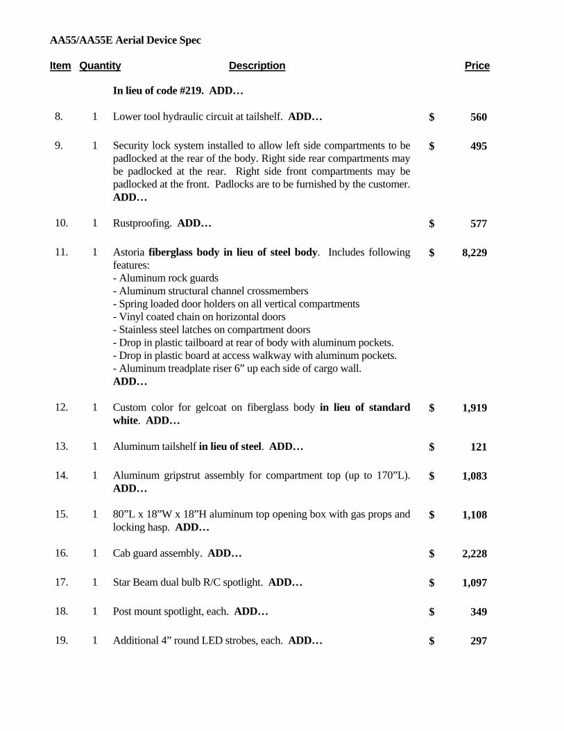
AA55/AA55E Aerial Device Spec Item Quantity Description Price
In lieu of code #219. ADD…
8. 1 Lower tool hydraulic circuit at tailshelf. ADD…
560$
9. 1 Security lock system installed to allow left side compartments to be padlocked at the rear of the body. Right side rear compartments may be padlocked at the rear. Right side front compartments may be padlocked at the front. Padlocks are to be furnished by the customer. ADD…
495$
10. 1 Rustproofing. ADD…
577$
11. 1 Astoria fiberglass body in lieu of steel body. Includes following features: - Aluminum rock guards - Aluminum structural channel crossmembers - Spring loaded door holders on all vertical compartments - Vinyl coated chain on horizontal doors - Stainless steel latches on compartment doors - Drop in plastic tailboard at rear of body with aluminum pockets. - Drop in plastic board at access walkway with aluminum pockets. - Aluminum treadplate riser 6” up each side of cargo wall. ADD…
8,229$
12. 1 Custom color for gelcoat on fiberglass body in lieu of standard white. ADD…
1,919$
13. 1 Aluminum tailshelf in lieu of steel. ADD…
121$
14. 1 Aluminum gripstrut assembly for compartment top (up to 170”L). ADD…
1,083$
15. 1 80”L x 18”W x 18”H aluminum top opening box with gas props and locking hasp. ADD…
1,108$
16. 1 Cab guard assembly. ADD…
2,228$
17. 1 Star Beam dual bulb R/C spotlight. ADD…
1,097$
18. 1 Post mount spotlight, each. ADD…
349$
19. 1 Additional 4” round LED strobes, each. ADD…
297$

AA55/AA55E Aerial Device Spec Item Quantity Description Price
20. 2 TST Underbody lights. ADD…
384$
21. 1 1200W inverter with GFI receptacle installed at curbside rear. ADD…
1,514$
22. 1 Hastings grounding reel with 50’ of 1/0 cable. Includes 3 point ground system with front and rear lugs. ADD…
3,529$
23. 1 Custom color code in lieu of standard white for steel portions of build. ADD…
1,028$
24. 1 Front bumper cone holder. Horizontal bar with pivot at curbside and locking pin at streetside. ADD…
599$
25. 1 Front bumper cone holder. Vertical storage with loops. ADD…
750$
Important Note: The Altec ISO-Grip™ System, an upper control system incorporating high resistance components at the boom tip, like the insulating upper boom and insulating lower boom insert, is not a primary protection system. These systems offer an additional layer of secondary dielectric protection for the operator, but they are not intended to replace safe work practices or primary methods of protection such as cover-up and the use of personal protection equipment, including rubber gloves and sleeves.

Altec Industries, Inc.
March 1, 2013
OH STS Contract #7751501908 LRV56/60 Tree Trimming Aerial Device
For 25,999k - 33k GVWR Chassis Application 56’/60’ Articulating Overcenter Aerial Device
Item Quantity Description Price
UNIT
1. 1 #217 Altec Model LRV56 Articulating Overcenter Aerial Device with an insulated lower boom, insulated upper boom and an insulated ISO-Grip™ (Patent Applied For) system at the boom tip, for installation behind the cab, built in accordance to Altec’s standard specifications and to include the following features:
A. Ground to Bottom of Platform Height: 56.3 feet (17.2 m) at 3.0 feet (0.9 m) from centerline of rotation
B. Working Height: 61.3 feet (18.7 m)
C. Maximum Reach to Edge of Platform with Upper Boom Overcenter: 46.1
feet at 8.4 foot platform height (14.1 m at 2.6 m).
D. Maximum Reach to Edge of Platform with Upper Boom Non-overcenter and Lower Boom at 125 degrees: 43.5 feet at 24.8 foot platform height (13.3 m at 7.6 m).
E. Side by Side Boom Configuration: Travel height approximately 12.25 feet
(3.7 m)
F. Lower Boom Articulation: 0 to 125° (35° beyond vertical) accomplished by single hydraulic cylinder with a spherical bearing at the lower boom

Altec Model LRV56 Item Quantity Description Price
connection. Equipped with integral holding valves which lock boom in place in the event of a hydraulic line failure and a cushion valve for controlled movement into position at maximum lower boom articulation.
G. Upper Boom Articulation: 270° in relation to lower boom, accomplished by
dual cylinders with maintenance free Patented walking link drive system. Cylinders are equipped with integral holding valves to lock boom in place in the event of hydraulic line failure or loss of power.
H. Pedestal-Subbase: Fabricated from a 16 inch outside diameter x ½ inch (406
x 13 mm) wall steel tube welded into a fabricated steel subbase. Rotation bearing support ring is 1-5/8 inches (41 mm) thick.
I. Lower Boom: Fabricated of 12 x 12 x ¼ inch (305 x 305 x 6 mm) wall steel
tubing. Length of lower boom is 254 inches (6452 mm) from centerline of lower pivot to centerline of outer pivot.
J. Lower Boom Fiberglass Insulator: Filament wound fiberglass insulator with
11-3/8 inch square X 5/8 inch (289 x 16 mm) wall thickness, located in lower end of lower boom. Provides 15 inch (381 mm) clear isolation gap.
K. Upper Boom: Filament wound fiberglass with 10 inch (254 mm) inside
diameter contains insulated conduit for routing of hydraulic lines and fully contains upper boom leveling system. End of boom shaft has ring for attachment of fall protection system lanyard.
L. Rotation: Continuous rotation provided by hydraulic motor driving through
a worm gear speed reducer and gear bearing. Capable of rotating full rated platform capacity up a 5° slope (9% grade). Gear box is rated at 22,378 inch pounds. ¾ inch attachment bolts are used
M. Platform: Molded fiberglass one-man, side-mounted, fixed mounting.
N. Mechanical Platform Leveling System: A positive mechanical
parallelogram system of fiberglass insulating rods. Adjustment of leveling system made with turnbuckles located inside the cover on the lower boom and by adjusting studs accessible from the lower end of the upper boom. Platform level adjustment is easily accessible from external location on lower pivot.
O. Platform Tilting System – mechanical pin type allows easy removal of
water or debris from the platform
P. Hydraulic System: Open center hydraulic system functions at 6.5 gpm and 3,100 psi (21 375 kPa). Includes 25 gallon (94.6 l) reservoir, suction

Altec Model LRV56 Item Quantity Description Price
strainer, return line filter, sectional control valves and plumbing.
Q. ISO-Grip™ System: The Altec ISO-Grip™ (Patent Applied For) System includes the following boom tip components that can provide an additional layer of secondary electrical contact protection. This is not a primary protection system.
1. Control Handle: An insulated single handle controller that is dielectrically tested to 40 kV AC with no more than 400 microampers of leakage. The control handle is green in color to differentiate it from other non-tested controllers. The handle also includes an interlock guard that reduces the potential for inadvertent boom operation.
2. Auxiliary Control Covers: Non-tested blue silicon covers for auxiliary controls.
3. Control Console: Non-tested non-metallic control console plate. 4. Boom Tip Covers: Non-tested non-metallic boom tip covers. The
covers are not dielectrically tested, but they may provide some protection against electrical hazards.
R. Hydraulic Tool Circuit: Single tool circuit at boom tip, including one (1) set
of Bruning HTMA quick disconnect couplings. Circuit provides 5 – 6 gpm (18.9 – 22.7 lpm) at 2,000 psi (13 789 kPa). Operates open center tools.
S. Upper Boom Storage Support: Cradle and tie down strap installed for
horizontal stow units. “Low Stow” position also available.
T. Outrigger/Boom Interlock System: Helps prevent operator from using unit until all outriggers are lowered.
U. Outrigger/Unit Selector Control: Located near the outrigger controls,
allows operator to divert hydraulic oil from machine circuit for outrigger operation. This reduces the potential for inadvertent outrigger movement during machine operation if outrigger controls are bumped.
V. Outrigger Motion Alarm: Provides audible alarm when any of the
outriggers are in motion.
W. Back-up Alarm, installed
X. Diagnostic Pressure Test Quick Disconnect Couplings: are located at the turntable to allow a mobile service technician to quickly and easily attach a test gauge to verify system and tool circuit pressure. This reduces life cycle cost.
Y. Manuals: Two (2) Operator’s and two (2) Maintenance/Parts manuals.

Altec Model LRV56 Item Quantity Description Price
Z. Paint: Painted white with the Altec Powder Coat Paint Process which
provides a finish-painted surface that is highly resistant to chipping, scratching, abrasion and corrosion. Paint is electro-statically applied to the inside as well as outside of fabricated parts then high temperature cured prior to assembly ensuring maximum coverage and protection.
2. 1 #395 Manual stow securing system
3. 1 #282 Pedestal & Subbase - Configuration for forestry package (behind the cab)
Pedestal and subbase welded together. One three bank valve for installation on curb side for outrigger, outrigger/unit selector and chip box, and one single bank valve for installation on street side for outrigger furnished.
4. 1 #241 Outriggers, Primary – Forestry package, swivel shoe A-frame, 154 inches (3912 mm) at maximum spread (outside of footpad to outside of footpad) and 7 inches penetration at 40 inch chassis frame height.
5. 1 #319 Category C, 46kV and below
6. 1 Pedestal – for behind cab mount
7. 1 #214 Single one man side mounted, fiberglass platform with shaft-mounted controls (controls are located on the side of the platform nearest the upper boom). Platform is 24 x 24 x 42 inches (610 x 610 x 1067 mm), and is rated at 350 pounds (159 kg)
8. 1 #296/310 Engine Start/Stop with Secondary Stowage System, 12 VDC electric powered. Includes pump and motor, operates from chassis battery. Control is captive air operated from the platform and toggle switch operated from the lower controls. This option allows the operator to completely stow the booms and platform in a situation wherein the primary hydraulic source fails.
NOTE: Requires code 397 Slip Ring
9. 1 #343 Throttle Control, Captive Air – Throttle relay and solenoid allows
operator to increase engine speed from platform.
10. 1 #397 Slip Ring NOTE: Required for engine start/stop and secondary stowage system options
11. 1 #251 Platform Cover – for single, side mounted platform, soft vinyl, 24 x 24

Altec Model LRV56 Item Quantity Description Price
inch (610 x 610 mm)
12. 1 #259 Platform Liner 50 kV – for single platform 24 x 24 x 42 inches (610 x 610 x 1067 mm)
13. 1 #229 Platform Step – located on front outside wall. In stowed position, step will be side of platform nearest elbow.
14. 1 Power Distribution Module is a compact self-contained electronic system that provides a standardized interface with the chassis electrical system. The Power Distribution Module (PDM) is composed of a main board, approximately 12.0 x 13.0 inches (305 x 330 mm), designed to be mounted behind the driver’s seat, inside the cab. Additional modules plug in to accommodate various options such as engine start/stop, variable throttle control, power take off, interface with Allison World transmission, and engine speed control module for specific engines and chassis. In addition to the above potential options, the PDM also provides up to 16 accessory circuits to be used for controlling other customer specified electrical components. The PDM includes built in test capabilities and diagnostic input, output and status LED’s to quickly assess the PDM’s performance. All components are circuit board mounted to facilitate replacement and reduce repair time should it be required. The PDM provides benefits to the customer by providing a standardized, centrally located box that greatly reduces troubleshooting time when evaluating ancillary electrical system malfunctions, thereby reducing maintenance costs.
15. 1 #294 Tool Circuit at Boom Tip, Dual Hydraulic – dual set of Bruning HTMA quick disconnect couplings provides 5.0 – 6.0 gpm at 2,000 psi (19 to 23 lpm at 13 789 kPa). This in lieu of standard single set of quick disconnect couplings. Operates open center tools.
16. 1 #355 Fall Protection System to include one body harness and decelerating type lanyard. Harness has adjustable slide buckle on shoulder straps, Velcro chest strap, interlocking buckles on leg straps and nylon web loop fall arrest attachment on back. Lanyard has built in shock absorber that allows 28 inches (711 mm) of automatic adjustability.
17. 1 #369 Shut-Off Valve – at return filter
UNIT AND HYDRAULIC ACCESSORIES
18. 1 Hydraulic Oil and Lubricants, installed.
19. 1 Hot shift PTO for automatic transmission.

Altec Model LRV56 Item Quantity Description Price
20. 1 Hydraulic pump, right hand rotation
21. 1 Pair, rubber wheel chocks – 10”L x 8”W x 5 ½”H, installed.
BODY
22. 1 Forestry Body, all components, except structural members, fabricated from A-60 galvanneal coated steel
A. Body: Chip Dump Body 14.5 cubic yard (11.1 m3) capacity 93 inches wide x 63 inches high x 132 inches long (2362 x 1600 x 3353 mm) with:
Structural Channel stringers and floor channel.
14 gauge roof. 14 gauge sides and front with full length die-formed reinforcing ribs
12 gauge floor plate with (4) full length die-formed reinforcing ribs. Rear top and sides of body reinforced for lower boom support. 22½ inches (571 mm) high tailgate, hinged curb side with provision to
hold open for dumping. 12 gauge rear under body skirt panels Truck-Lite lighting package with rubber grommet shock mounts and wiring
harness in automotive type loom. Class “C” Hydraulic hoist, installed, with 45 degree dump angle and
body prop. Street side built-in ladder compartment, 12 inches wide x 26 inches high
(305 x 660 mm) with rear plastisol. Roller and internal security chain. Pole pruner compartment, 11 inches high (279.4 mm), above ladder
compartment with rear locking door. Interior of chip body finished with coal tar epoxy. Underside of chip body undercoated (except stringer channels). Front of chip box to be tapered at 45 degrees
B. Thru Box: Thru Box tool compartment 48 inches wide x 50 inches high x 93.5 inches long (1219 x 1270 x 2375 mm) with 26.5 inch (673 mm) deep curb and street side compartments with the following compartmentation:
14 gauge top plate 16 gauge side and bottom panels Street side – single compartment with vertical doors, not over-lapped. Left
side has two (2) fixed shelves. Right side has four (4) unequal transverse compartments open to curb side. Compartment bottom 0.5-inch (12.7 mm) plywood liner partitioned for chain saw gas can and wedge storage. Security chain for chain saw provided in bottom.
Curb side – single compartment with vertical doors, not over-lapped. Left

Altec Model LRV56 Item Quantity Description Price
side has four (4) unequal transverse compartments open to street side. All compartments have 0.5-inch (12.7 mm) plywood shelf liners. Top center has two (2) fixed shelves. Top right has six (6) swivel rope hooks (3-0-3).
All grip on walking surfaces.
C. Standard features:
Rivet door locks. Double acting spring type door holders. Door locks are attached by rivets. Paint compartment interiors gray. Rain deflectors above all doors.
23. 1 Cab Guard
24. 1 Cab Guard Accessory Kit.
25. 1 Cab Guard Access Ladder.
26. 2 Wheel chock holders, installed
BODY ACCESSORIES
27. 2 Splash aprons, installed
28. 1 Triangular reflector kit, installed behind seat
29. 1 Fire extinguisher, 5 pounds, with bracket, shipped loose
30. 1 Pintle hook, BP-100A Buyers Products, mounted 22-23 inches (559 – 584 mm)
above ground (unloaded), to include safety chain eyes.
31. 1 Front bumper assembly, installed
32. 1 Manual Pouch installed behind driver’s side seat.
ELECTRICAL ACCESSORIES
33. 1 Lights and reflectors in accordance with FMVSS #108 lighting package installed.
34. 1
6-way trailer receptacle, includes wiring harness installed at rear.

Altec Model LRV56 Item Quantity Description Price
35. 1 Outrigger Motion Alarm: Provides audible alarm when any of the outriggers are in motion.
36. 1 Backup alarm, installed at rear
37. 1 Hour meter installed to record PTO operating hours
38. 2 LED Strobe lights, installed one on cab guard and one at rear corner of chip box.
39. 1 Install Altec MP System for in-cab accessory switch panel. Includes dual lit switches for function identification and function activation.
INSTALLATION
40. 1 Install Altec aerial device
41. 1 Altec Aerial Device painted white with the Altec Powder Coat Paint Process which provides a finish-painted surface that is highly resistant to chipping, scratching, abrasion and corrosion. Paint is electro-statically applied to the inside as well as outside of fabricated parts then high temperature cured prior to assembly ensuring maximum coverage and protection
42. 1 Mounting body and accessories
43. 1 Painting body and accessories white with urethane enamel
44. 1 Safety and instructional signs installed
45. 1 Vehicle height placard is to be placed in view of the driver
46. 1 Delivery of completed vehicle
47. 1 DOT certification of completed vehicle
48. 1 Paint underneath black – 99A.
49. 1 Ferrox applied to all walking surfaces.
50. 1 All steel parts phosphate pressure washed and prime painted.
51. 1 Test complete unit in accordance with OSHA/ANSI requirements and provide documentation.
MISCELLANEOUS

Altec Model LRV56 Item Quantity Description Price
52. 1 One (1) year parts warranty
53. 1 One (1) year labor warranty
54. 1 Ninety (90) days warranty for travel charges
55. 1 Bidder is to supply a self-directed, computer based training (CBT) program.
This program will provide basic instruction in the safe operation of this aerial device. This program will also include and explain ANSI and OSHA requirements related to the proper use and operation of this unit.
56. 1 For so long as the initial purchaser owns the product, major components warranty at an Altec service facility (See Altec Limited Warranty)
LIST PRICE
87,044.00$
STATE DISCOUNT
7,913.00$
STATE PRICE
79,131.00$
RECOMMENDED CHASSIS
FOR LRV56: CA: 120”
GVWR: 25,950lb FAWR: 10,000lb RAWR: 19,000lb
FOR LRV60: CA:138”
GVWR: 33,000lb FAWR: 12,000lb RAWR: 21,000lb
See chassis specs, options, and pricing at end of Pricelist
OPTIONS
1. 1 LRV60 in lieu of 55’ aerial. ADD…
1,632$
2. 1 24x30 platform, liner, and cover. ADD…
123$
3. 1 Painting unit, body, steel accessories customer specific color code. 1,037$

Altec Model LRV56 Item Quantity Description Price
ADD…
4. 1 Two (2) DICA 24x22x1 outrigger pads installed in holders. ADD…
510$
5. 1 Additional 4” round LED amber strobes, each. ADD…
297$
6. 1 Automatic Boom Stow. ADD…
816$
7. 1 Upper tool circuit active while relocating aerial device. ADD…
572$
8. 1 Rustproofing. ADD…
577$
Important Note: The Altec ISO-Grip™ System, like the insulated upper boom and insulated lower boom insert, is not a primary protection system. These systems offer an additional layer of secondary dielectric protection for the operator, but they are not intended to replace safe work practices or primary methods of protection such as cover-up and the use of personal protection equipment, including rubber gloves and sleeves.

March 1, 2013
OH STS Contract #7751501908
LRV60-E70 Tree Trimming Aerial Device For 33k GVWR Chassis Application
70’ Overcenter Articulating Aerial Device Item Quantity Description Price
UNIT
1. 1 #209 Altec Model LRV60-E70 Articulating Overcenter Aerial Device with an insulated lower boom, insulated upper boom and elevator and an insulated ISO-Grip™ (Patent Applied For) system at the boom tip, for installation behind the cab, built in accordance to Altec’s standard specifications and to include the following features:
A. Ground to Bottom of Platform Height: 69.7 feet (21.2 m) at 3.0 feet (0.9 m) from centerline of rotation
B. Working Height: 74.7 feet (22.8 m)
C. Maximum Reach to Edge of Platform with Upper Boom Overcenter:
49.1 feet at 18.4 feet platform height (15.0 m at 5.6 m).
D. Maximum Reach to Edge of Platform with Upper Boom Non-overcenter and Lower Boom at 125 degrees: 45.1 feet at 37.3 foot platform height (13.7 m at 11.4 m).
E. Side by Side Boom Configuration: Travel height approximately 12’7”
on a chassis with approximately 40” frame height. (With standard 89” pedestal height. This may have to be increased depending on cab configuration.)
F. Lower Boom Articulation: 0 to 125 degrees (35 degrees beyond
vertical) accomplished by single hydraulic cylinder with a spherical bearing at the lower boom connection. Equipped with integral holding valves which lock boom in place in the event of a hydraulic
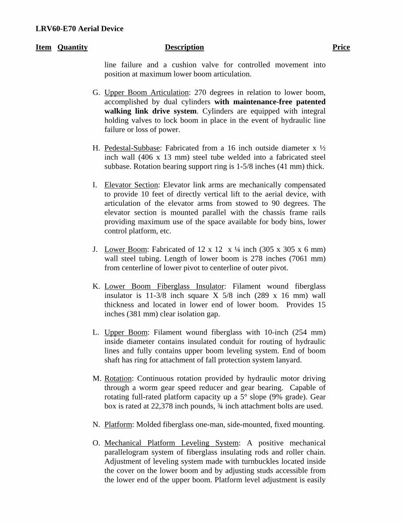
LRV60-E70 Aerial Device Item Quantity Description Price
line failure and a cushion valve for controlled movement into position at maximum lower boom articulation.
G. Upper Boom Articulation: 270 degrees in relation to lower boom,
accomplished by dual cylinders with maintenance-free patented walking link drive system. Cylinders are equipped with integral holding valves to lock boom in place in the event of hydraulic line failure or loss of power.
H. Pedestal-Subbase: Fabricated from a 16 inch outside diameter x ½
inch wall (406 x 13 mm) steel tube welded into a fabricated steel subbase. Rotation bearing support ring is 1-5/8 inches (41 mm) thick.
I. Elevator Section: Elevator link arms are mechanically compensated
to provide 10 feet of directly vertical lift to the aerial device, with articulation of the elevator arms from stowed to 90 degrees. The elevator section is mounted parallel with the chassis frame rails providing maximum use of the space available for body bins, lower control platform, etc.
J. Lower Boom: Fabricated of 12 x 12 x ¼ inch (305 x 305 x 6 mm)
wall steel tubing. Length of lower boom is 278 inches (7061 mm) from centerline of lower pivot to centerline of outer pivot.
K. Lower Boom Fiberglass Insulator: Filament wound fiberglass
insulator is 11-3/8 inch square X 5/8 inch (289 x 16 mm) wall thickness and located in lower end of lower boom. Provides 15 inches (381 mm) clear isolation gap.
L. Upper Boom: Filament wound fiberglass with 10-inch (254 mm)
inside diameter contains insulated conduit for routing of hydraulic lines and fully contains upper boom leveling system. End of boom shaft has ring for attachment of fall protection system lanyard.
M. Rotation: Continuous rotation provided by hydraulic motor driving
through a worm gear speed reducer and gear bearing. Capable of rotating full-rated platform capacity up a 5° slope (9% grade). Gear box is rated at 22,378 inch pounds, ¾ inch attachment bolts are used.
N. Platform: Molded fiberglass one-man, side-mounted, fixed mounting.
O. Mechanical Platform Leveling System: A positive mechanical
parallelogram system of fiberglass insulating rods and roller chain. Adjustment of leveling system made with turnbuckles located inside the cover on the lower boom and by adjusting studs accessible from the lower end of the upper boom. Platform level adjustment is easily

LRV60-E70 Aerial Device Item Quantity Description Price
accessible from external location on lower pivot.
P. Platform Tilting System – mechanical pin type allows easy removal of water or debris from the platform
Q. Hydraulic System: Open-center hydraulic system functions at 6.5
gpm and 3,100 psi (21 375 kPa, 214 bar). Includes 25 gallon (94.6 l) reservoir, suction strainer, return line filter, sectional control valves and plumbing.
R. ISO-Grip™ System: The Altec ISO-Grip™ (Patent Applied For)
System includes the following boom tip components that can provide an additional layer of secondary electrical contact protection. This is not a primary protection system.
1. Control Handle: An insulated single handle controller that is dielectrically tested to 40 kV AC with no more than 400 microampers of leakage. The control handle is green in color to differentiate it from other non-tested controllers. The handle also includes an interlock guard that reduces the potential for inadvertent boom operation.
2. Auxiliary Control Covers: Non-tested blue silicon covers for auxiliary controls.
3. Control Console: Non-tested non-metallic control console plate.
4. Boom Tip Covers: Non-tested non-metallic boom tip covers. The covers are not dielectrically tested, but they may provide some protection against electrical hazards.
S. Hydraulic Tool Circuit: Single tool circuit at boom tip, including one
(1) set of Bruning HTMA quick disconnect couplings. Circuit provides 5 - 6.0 gpm (18.9 - 22.7 lpm) at 2,000 psi (13 789 kPa). Operates open center tools.
T. Upper Boom Storage Support: Cradle and tie down strap installed for
horizontal stow units.
U. Outrigger/Boom Interlock System: Helps prevent operator from using unit until all outriggers are lowered.
V. Outrigger/Unit Selector Control: Located near the outrigger controls,
allows operator to divert hydraulic oil from machine circuit for outrigger operation. This reduces the potential for inadvertent outrigger movement during machine operation if outrigger controls are bumped.
W. Outrigger Motion Alarm: Provides audible alarm when any of the

LRV60-E70 Aerial Device Item Quantity Description Price
outriggers are in motion.
X. Back-up Alarm, installed
Y. Preventative Maintenance: Unit owner can select means of tracking maintenance intervals by calendar time or PTO hours. If the owner selects calendar driven cycles, preventative maintenance is required no more frequently than every 6 months. If the owner selects PTO hour driven cycles, preventative maintenance interval is likely to be greater than 6 months. Both programs allow the equipment owner to lower life cycle costs through higher product uptime and lower maintenance costs.
Z. Diagnostic Pressure Test Quick Disconnect Couplings: are located at
the turntable to allow a mobile service technician to quickly and easily attach a test gauge to verify system and tool circuit pressure. This reduces life cycle cost.
AA. Manuals: Two (2) Operator’s and two (2) Maintenance/Parts
manuals.
BB. Paint: Painted white with the Altec Powder Coat Paint Process which provides a finish-painted surface that is highly resistant to chipping, scratching, abrasion and corrosion. Paint is electro-statically applied to the inside as well as outside of fabricated parts then high temperature cured prior to assembly ensuring maximum coverage and protection.
2. 1 #395 Manual stow securing system
3. 1 #241 Outriggers, Primary – 36 to 40 inch (914 to 1016 mm) chassis
height. Forestry package, 5-degree swivel shoe A-frame, 154 inches (3912 mm) at maximum spread (outside of footpad to outside of footpad) and 7 inches (178 mm) penetration at a 40-inch chassis height. One three bank valve for installation on curb side for outrigger, outrigger/unit selector and chip box, and one single bank valve for installation on street side for outrigger furnished.
4. 1 #319 Category C, 46kV and below
5. 1 #212 Single one-man side-mounted, fiberglass platform with shaft-mounted controls (controls are located on the side of the platform nearest the upper boom). Platform is 24 x 24 x 39 inches (610 x 610 x 991 mm), and is rated at 350 pounds (159 kg)

LRV60-E70 Aerial Device Item Quantity Description Price
6. 1 #251 Platform Cover – Soft vinyl, 24 x 24 inch (610 x 610 mm)
7. 1 #257 Platform Liner 50 kV – 24 x 24 x 39 inches (610 x 610 x 991 mm)
8. 1 #233 Platform Liner Floor – 24 x 24 inches with safety tread (610 x 610 mm)
9. 1 #229 Platform Step – located on outside wall. In stowed position, step will be side of platform nearest elbow.
10. 1 #296 Secondary Stowage System – 12 VDC electric powered, captive air controlled from the platform; momentary switch located at lower controls; includes pump and motor, operates from chassis battery NOTE: Requires code 397 Slip Ring
11. 1 #397 Slip Ring NOTE: Required for engine start/stop and secondary stowage system options
12. 1 #294 Tool Circuit at Boom Tip, Dual Hydraulic – dual set of Bruning HTMA quick disconnect couplings provides 5.0 – 6.0 gpm at 2,000 psi (19 to 23 lpm at 13 789 kPa). This in lieu of standard single set of quick disconnect couplings. Operates open center tools.
13. 1 #355 Fall Protection System to include one body harness and decelerating type lanyard. Harness has adjustable slide buckle on shoulder straps, Velcro chest strap, interlocking buckles on leg straps and nylon web loop fall arrest attachment on back. Lanyard has built in shock absorber that allows 28 inches (711 mm) of automatic adjustability.
UNIT AND HYDRAULIC ACCESSORIES
14. 1 Hydraulic Oil and Lubricants
15. 1 Air shift PTO for manual transmission.
16. 1 Hydraulic Pump
BODY
17. 1 Forestry Body with all components, except structural members, fabricated from A-60-galvanneal coated steel:

LRV60-E70 Aerial Device Item Quantity Description Price
18. A. Body: Chip Dump Body 14.5 cubic yard (11.1 m3) capacity 93 inches wide x 63 inches high x 132 inches long (2362 x 1600 x 3353 mm) with:
Structural Channel stringers and floor channel. 12 gauge minimum floor plate. 14 gauge minimum sides and front with full length die-formed
reinforcing ribs. 14 gauge roof. Rear top and sides of body reinforced for lower boom support. 22½ inches (571 mm) high tailgate, hinged curb side with provision
to hold open for dumping. 12 gauge minimum rear under body skirt panel. Class “C” Hydraulic hoist, installed, with 45 degree dump angle
and body prop. Lighting package with rubber grommet shock mounts and wiring
harness in automotive type loom. Street side built-in ladder compartment, 12 inches wide x 25 inches high
(305 x 635 mm) with rear roller and internal security chain. Pole pruner compartment, 11 inches high (279.4 mm), above ladder
compartment with rear locking door. Interior of chip body finished with coal tar epoxy. Underside of chip body undercoated (except stringer channels).
B. Compartmentation—Street side:
Single compartment (66 inches long x 50 inches high x 26.5 inches
deep) with three (3) vertical doors. Two (2) full width shelves fixed at 11 inches and 25 inches from top. Holder for chain saw provided in bottom on left side. Right side has access to horizontal thru compartment extending from curb side platform.
C. Compartmentation—Curb side:
Single compartment (41 inches long x 50 inches high x 26.5 inches deep) with two (2) vertical doors. Left side has two (2) full width shelves fixed at 11 inches and 25 inches from top. Right side has six (6) material hooks (3-0-3). Platform mounted behind compartment 12 inches high x 25 inches wide x 26.5 inches deep. Horizontal thru compartment (6 inches high) recessed 12 inches, open to street side with vertical partitions spaced 10 inches, 6 inches and 9 inches wide with drop-down door.
D. Standard features:
Rivet door locks.

LRV60-E70 Aerial Device Item Quantity Description Price
Double acting spring type door holders. Door locks are three point twist with lock cylinders Paint compartment interiors gray. Rain deflectors above all doors
19. 1 Cab Guard
20. 1 Front bumper assembly
21. 1 Cab Guard Accessory Kit.
22. 1 Cab Guard Access step mounted on rear of curb side compartment.
23. 1 Stirrup step under curb side platform with two (2) grab handles.
24. 2 Outrigger pad holders, to accommodate outrigger pads 19.5 x 19.5 x
1.875 inches (Wooden with orange metal band)
25. 2 Wheel chock holders, to accommodate wheel chocks – rubber (ribbed type)
BODY ACCESSORIES
26. 2 Splash Aprons installed
27. 1 Triangular reflector kit, installed behind seat
28. 1 Fire extinguisher, 5 pounds, with bracket, shipped loose
29. 1 Pintle hook, T100 style, and hitch assembly mounted 22-23 inches (559 – 584 mm) (based on a 40” frame height) above ground (unloaded). Includes safety chain eyes.
30. 2 Outrigger pads 19.5 x 19.5 x 1.875 inches (Wooden with orange metal band)
31. 2 Wheel Chocks – rubber (ribbed type)
32. 1 Manual Pouch installed behind driver’s side seat.
ELECTRICAL ACCESSORIES
33. 1 Lights and reflectors in accordance with FMVSS #108 lighting package.
34. 1 6-way trailer receptacle, includes wiring harness installed at rear.

LRV60-E70 Aerial Device Item Quantity Description Price
35. 1 Install Outrigger Motion Alarm: Provides audible alarm when any of the
outriggers are in motion.
36. 1 Install secondary stowage with momentary switch for installation near outrigger controls
37. 2 LED Strobe lights installed streetside, one under cab guard and one at rear corner of chip box
INSTALLATION
38. 1 Install Altec aerial device
39. 1 Altec Aerial Device painted white with the Altec Powder Coat Paint Process which provides a finish-painted surface that is highly resistant to chipping, scratching, abrasion and corrosion. Paint is electro-statically applied to the inside as well as outside of fabricated parts then high temperature cured prior to assembly ensuring maximum coverage and protection
40. 1 Mounting body and accessories
41. 1 Painting body and accessories white with urethane enamel
42. 1 Paint cab guard black
43. 1 Paint underneath black
44. 1 Ferrox applied to all walking surfaces.
45. 1 Safety and instructional signs installed
46. 1 Vehicle height placard is to be placed in view of the driver
47. 1 Delivery of completed vehicle
48. 1 Tests complete unit in accordance with OSHA/ANSI requirements and provide documentation.
MISCELLANEOUS
49. 1 This aerial device is to be designed in a facility that is certified to meet ISO 9001

LRV60-E70 Aerial Device Item Quantity Description Price
50. 1 One (1) year parts warranty
51. 1 One (1) year labor warranty
52. 1 Ninety (90) days warranty for travel charges
53. 1 Warranty on structural integrity of the following major components is to
be warranted for so long as the initial purchaser owns the product: Booms, boom articulation links, hydraulic cylinder structures, outrigger weldments, pedestals, subbases and turntables.
54. 1 Bidder is to supply a self-directed, computer based training (CBT) program. This program will provide basic instruction in the safe operation of this aerial device. This program will also include and explain ANSI and OSHA requirements related to the proper use and operation of this unit.
LIST PRICE
107,767.00$
STATE DISCOUNT
9,797.00$
STATE PRICE
97,970.00$
RECOMMENDED CHASSIS
CA: 138” FAWR: 12,000lbs RAWR: 21,000lbs GVWR: 33,000lbs
OPTIONS
1 Custom color code in lieu of white for steel portions of unit/body. ADD…
1,028$
1 Automatic Boom Stow. ADD…
816$

LRV60-E70 Aerial Device Item Quantity Description Price
1 Upper tool circuit active while relocating aerial device. ADD…
572$
1 Front bumper cone holder. Horizontal bar with pivot at curbside and locking pin at streetside. ADD…
599$
1 Front bumper cone holder. Vertical storage with loops with drop down feature. ADD…
750$
Important Note: The Altec ISO-Grip™ System, like the insulated upper boom and insulated lower boom insert, is not a primary protection system. These systems offer an additional layer of secondary dielectric protection for the operator, but they are not intended to replace safe work practices or primary methods of protection such as cover-up and the use of personal protection equipment, including rubber gloves and sleeves.

Page 1
Altec Industries, Inc.
March 1, 2013
OH STS Contract #7751501908
DM45/47/50 Digger Derrick For 33k-37k GVWR Chassis Application
45’/47’/50’ Sheave Height Hydraulic Digger Derrick
Item Quantity Description Price UNIT
1. 1 Altec Model DM45 Hydraulic Derrick, Rear mount, designed for
mounting over rear axle with a Turntable winch, built in accordance with Altec Industries standard specifications and to include the following features:
Maximum Sheave Height 44.4 ft
Maximum Horizontal Reach 35.0 ft
Maximum Digging Radius 24.8 ft
Elevation – From 80 degrees above horizontal to 20 degrees below horizontal
A. Unit meets or exceeds ANSI 10.31-1995. Unit serial number placard clearly states compliance.
B. Unit is designed and manufactured in facilities that are certified to meet
ISO 9001 requirements.
C. Winch: 15,000 pound bare drum capacity turntable winch with 8.625” diameter drum to comply with ANSI 10.31 Section 4.10.4 for synthetic rope or 15,000 pound bare drum capacity boom tip winch. High torque hydraulic motor drives a self-locking worm gear winch.

State of OH DM45-47-50 Spec Item Quantity Description Price
Counterbalance valves on motor provide reliable load holding
D. Insulated, “46 kV and below”
E. Hydraulic Overload Protection System – activates when unit is exposed to overload condition. System prevents actuation of all functions that could add to the overload condition including: - Boom Lower - Intermediate Boom Extend - Third Stage Boom Extend - Winch Raise - Auger Dig System automatically resets when overload condition is relieved.
F. Hydraulic Side Load Protection relieves overload conditions by allowing rotation system to back drive.
G. System pressure gauges on all vehicle mounted main control stations.
H. Transferable Boom Flares include adjustable alignment guides.
I. Pole Guides – cylinder driven open/close and tilt includes double pilot
operated check valves to support poles in both tilt directions. Also includes tilt interlock that prevents the upper boom from extending when the transferable flares are attached to the intermediate boom until the guides are articulated to the full up position.
J. Fiberglass Boom Tip with provisions for platform attachment.
K. Two-part load line attachment point on intermediate boom.
L. Full capacity fiberglass upper boom is round and is fabricated using a
Centrifically Cast process that provides a smooth surface finish inside and out that is easy to clean and is highly resistant to damage.
M. Cylinders: Rods are chrome plated and ends are threaded and welded.
N. Bearings: Lift cylinder equipped with self-aligning bearings. All
extending booms utilize slide bearings; there are no roller bearings on extending booms.
O. Proportional-Hydraulic Control System: The electrical control panel(s)
and pilot hydraulic system provide easy to operate controls with superior metering. There are only two hydraulic lines through rotation. Hydraulic control valves for Rotation, Boom Elevation,

State of OH DM45-47-50 Spec Item Quantity Description Price
Boom Extension, Digger and Winch are pilot operated and controlled by a proportional pilot system which provides full metering and feathering characteristics. There are no hydraulic lines within operator control station.
P. Control system includes single quick connect plug for quick and easy
installation of radio remote control system in the field upon request.
Q. Standard/Low Speed Selector allows an operator to select standard or low functional speeds without respect to engine throttle. When in standard mode, each function operates at normal speeds. When in low mode, the maximum operational speed of each function is approximately half that of the standard speed, providing a more meterable feel. The function is separate from engine throttle control, giving the operator additional fine tuning speed control.
R. Hydraulic Dump Valve installed in pedestal: Provides extra protection
by diverting hydraulic flow away from the main control valve when unit is idle. Dump valve solenoid is electronically activated when a function is operated.
S. Boom Storage Protection System – switch on main boom activates
hydraulic overload protection system to prevent operator from inadvertently placing excessive down force on boom stow bracket.
T. Continuous rotation including worm drive rotation gearbox. With
booms horizontal and fully extended, unit is able to rotate a 500 lbs load on winch line at boom tip up a 5 degree slope.
U. Manual Override of Hydraulic Functions at main control valve.
V. Complete Hydraulic System including:
1. Magnetic suction separator
2. Return line filter with cold oil indicator 3. Hydraulic pressure gauges
W. Outrigger/Boom Interlock System: Helps prevent operator from using unit until all outriggers are lowered.
X. Outrigger/Unit Selector Control: Located near the outrigger controls,
allows operator to divert hydraulic oil from machine circuit for outrigger operation. This reduces the potential for inadvertent outrigger movement during machine operation if outrigger controls are bumped.
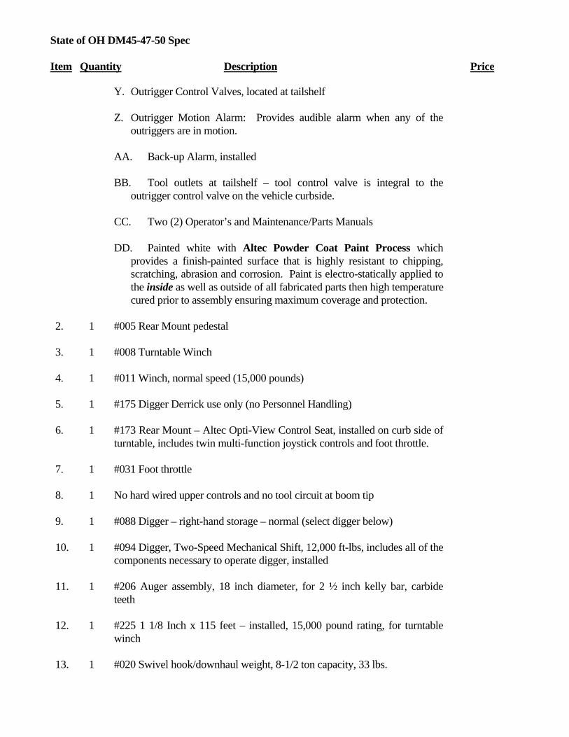
State of OH DM45-47-50 Spec Item Quantity Description Price
Y. Outrigger Control Valves, located at tailshelf
Z. Outrigger Motion Alarm: Provides audible alarm when any of the outriggers are in motion.
AA. Back-up Alarm, installed
BB. Tool outlets at tailshelf – tool control valve is integral to the
outrigger control valve on the vehicle curbside.
CC. Two (2) Operator’s and Maintenance/Parts Manuals
DD. Painted white with Altec Powder Coat Paint Process which provides a finish-painted surface that is highly resistant to chipping, scratching, abrasion and corrosion. Paint is electro-statically applied to the inside as well as outside of all fabricated parts then high temperature cured prior to assembly ensuring maximum coverage and protection.
2. 1 #005 Rear Mount pedestal
3. 1 #008 Turntable Winch
4. 1 #011 Winch, normal speed (15,000 pounds)
5. 1 #175 Digger Derrick use only (no Personnel Handling)
6. 1 #173 Rear Mount – Altec Opti-View Control Seat, installed on curb side of
turntable, includes twin multi-function joystick controls and foot throttle.
7. 1 #031 Foot throttle
8. 1 No hard wired upper controls and no tool circuit at boom tip
9. 1 #088 Digger – right-hand storage – normal (select digger below)
10. 1 #094 Digger, Two-Speed Mechanical Shift, 12,000 ft-lbs, includes all of the components necessary to operate digger, installed
11. 1 #206 Auger assembly, 18 inch diameter, for 2 ½ inch kelly bar, carbide teeth
12. 1 #225 1 1/8 Inch x 115 feet – installed, 15,000 pound rating, for turntable winch
13. 1 #020 Swivel hook/downhaul weight, 8-1/2 ton capacity, 33 lbs.

State of OH DM45-47-50 Spec Item Quantity Description Price
14. 1 #044 Outriggers, A-frame, folding shoe, 153 inch maximum spread,
auxiliary outriggers.
15. 1 #450 Outriggers, A-frame, folding shoe, 153 inch maximum spread, for use as primary outriggers.
16. 1 #501 Power Distribution Module, shipped loose. The Power Distribution Module is a compact self-contained electronic system that provides a standardized interface with the chassis electrical system. The Power Distribution Module (PDM) is composed of a main board, approximately 12.0 x 13.0 inches (305 x 330 mm), designed to be mounted behind the driver’s seat, inside the cab. Additional modules plug in to accommodate various options such as engine start/stop, variable throttle control, power take off, interface with Allison World transmission, and engine speed control module for specific engines and chassis. In addition to the above potential options, the PDM also provides up to 16 accessory circuits to be used for controlling other customer specified electrical components. The PDM includes built in test capabilities and diagnostic input, output and status LED’s to quickly assess the PDM’s performance. All components are circuit board mounted to facilitate replacement and reduce repair time should it be required. The PDM provides benefits to the customer by providing a standardized, centrally located box that greatly reduces troubleshooting time when evaluating ancillary electrical system malfunctions, thereby reducing maintenance costs, shipped loose.
17. 1 #132 Altec Electronic Side Load Protection (eSLP)™ - includes indicator gauge and lamp
18. 1 #134 Altec RotaFloat – includes alarm and visual indicator
19. 1 #077 Reservoir Assembly – includes 60 gallon reservoir, filter, and magnetic suction separator
20. 1 #060 Pole Puller – with 7 feet of 5/8 inch high-tensile chain and base
21. 1 Custom option - through storage for digger derrick pedestal.
UNIT AND HYDRAULIC ACCESSORIES
22. 1 Hydraulic oil and lubricants, installed
23. 1 Hydraulic pump – right-hand rotation, 14/21 @ 1,200 rpm, tandem vane

State of OH DM45-47-50 Spec Item Quantity Description Price
24. 1 Cab control, heavy duty SAE PTO
25. 1 Subbase assembly for mounting of derrick pedestal and outriggers, to
consist of 6 inch x 4 inch tubing (3/8 inch wall) each side of chassis frame with top and bottom plate. To include longitudinal through storage with drop down door at rear. Stops in center and side tubes at 120”.
26. 1 Samson Nylite spool shield
27. 1 Pair, rubber wheel chocks, 10”L x 8”W x 5 ½”H.
28. 1 8-1/2 foot x 3/8 inch nylon wind up sling
29. 1 Spring operated hydraulic hose reel for storage of two (2) 35 feet lengths of hose, installed.
30. 1 0-8 GPM flow divider, variable for installation of tools at tailshelf
BODY
30. 1 158 inch body, suitable for installing on any single rear axle chassis with 120 inch CA dimension. Body is built in accordance with our standard specifications, including:
A. Body: Fabricated from A60 grade 100% zinc alloy coated steel with the following minimum gauge thickness:
1. 16 gauge outside panels
2. 16 gauge top panels 3. 14 gauge end panels 4. 20 gauge inner door panels 5. 20 gauge outer door panels 6. 18 gauge shelving, spangled steel 7. 14 gauge wheel panels 8. 12 gauge safety tread steel floor (four-way pattern) 9. Structural channel crossmembers 10. Galvannealed treadplate installed on top of body compartments 11. Wheel chock holders installed one (1) each side of body in
fender panel 12. Gripstrut on top of right side compartments behind access step 13. Radial wheel well liners 14. Rope lighting
B. Body Dimensions:

State of OH DM45-47-50 Spec Item Quantity Description Price
1. 158 inch overall body length
2. 93 inch outside width 3. 46 inch body height 4. 18 inch compartment depth 5. 57 inch floor width
C. Compartmentation – Curb Side:
1. First Vertical – Five (5) material hooks 2. Second Vertical – Access walkway 3. Third Vertical – Seven (7) locking swivel material hooks (2-3-
2) 4. Horizontal – Two (2) fixed shelves with removable dividers on
8 inch centers 5. Rear Vertical – Four (4) locking swivel material hooks.
Includes cutout for rear outrigger leg.
D. Compartmentation – Street Side:
1. First Vertical – Three (3) adjustable shelves with removable dividers on 4 inch centers
2. Second Vertical – Five (5) material hooks 3. Third Vertical – Five (5) material hooks 4. Horizontal – One (1) plain fixed shelf 5. Rear Vertical – Four (4) locking swivel material hooks.
Includes cutout for rear outrigger leg. 6. Through Shelf – Full length of left side of body with hotstick
brackets and rear door
E. Standard Features:
1. Basic body fabricated from A60 grade 100% zinc alloy coated steel
2. All doors are full, double paneled, self-sealed with built-in drainage for maximum weather-tightness. Electro-zinc plated, steel hinge rods extend full length of door. Door hinges are zinc alloy material attached with rivets.
3. All doors contain zinc plated flush type, single point paddle type locks with recessed handles, including keyed locks and adjustable two-stage strikers. Door handles are riveted to the outer door panel. Back panel has opening for easy access.
4. Heavy-gauge welded steel base construction with safety tread floor.
5. All edges are either rolled or folded for strength and safety
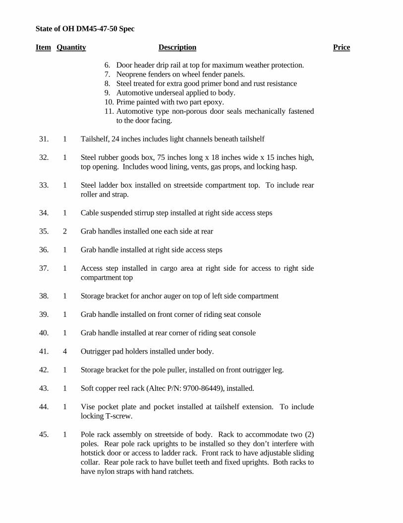
State of OH DM45-47-50 Spec Item Quantity Description Price
6. Door header drip rail at top for maximum weather protection. 7. Neoprene fenders on wheel fender panels. 8. Steel treated for extra good primer bond and rust resistance 9. Automotive underseal applied to body. 10. Prime painted with two part epoxy. 11. Automotive type non-porous door seals mechanically fastened
to the door facing.
31. 1 Tailshelf, 24 inches includes light channels beneath tailshelf
32. 1 Steel rubber goods box, 75 inches long x 18 inches wide x 15 inches high, top opening. Includes wood lining, vents, gas props, and locking hasp.
33. 1 Steel ladder box installed on streetside compartment top. To include rear roller and strap.
34. 1 Cable suspended stirrup step installed at right side access steps
35. 2 Grab handles installed one each side at rear
36. 1 Grab handle installed at right side access steps
37. 1 Access step installed in cargo area at right side for access to right side compartment top
38. 1 Storage bracket for anchor auger on top of left side compartment
39. 1 Grab handle installed on front corner of riding seat console
40. 1 Grab handle installed at rear corner of riding seat console
41. 4 Outrigger pad holders installed under body.
42. 1 Storage bracket for the pole puller, installed on front outrigger leg.
43. 1 Soft copper reel rack (Altec P/N: 9700-86449), installed.
44. 1 Vise pocket plate and pocket installed at tailshelf extension. To include locking T-screw.
45. 1 Pole rack assembly on streetside of body. Rack to accommodate two (2) poles. Rear pole rack uprights to be installed so they don’t interfere with hotstick door or access to ladder rack. Front rack to have adjustable sliding collar. Rear pole rack to have bullet teeth and fixed uprights. Both racks to have nylon straps with hand ratchets.

State of OH DM45-47-50 Spec Item Quantity Description Price
46. 1 Rope style compartment lights installed in each compartment. Wiring
installed in loom with switch located in cab. Switch to be energized only when chassis lights are on.
47. 1 Derrick storage support with auxiliary storage saddle for use when carrying poles.
BODY ACCESSORIES
48. 2 NuSteps installed one each side at rear
49. 1 Two (2) D-Rings installed on rear of primary outriggers.
50. 1 Pintle hook with frame reinforcement and two safety chain rings installed at 28 inches (+/- 1 inch) from ground to center of eye
51. 1 (Set) splash aprons, installed behind rear wheels
52. 1 Triangular reflector kit installed in cab behind seat on passenger’s side
53. 4 Wood outrigger pads 24x24x3.
54. 2 Ten pound fire extinguisher with mounting bracket, shipped loose
55. 1 Rubber dock bumpers installed on right and left side of frame at rear
ELECTRICAL ACCESSORIES
56. 1 LED Lights and reflectors in accordance with FMVSS #108 lighting package, installed
57. 1 Electric brake controller, installed
58. 2 LED Amber strobe light installed on each side of derrick storage support with master switch and indicator light installed in cab.
59. 1 Four corner LED strobe system: A) Two (2) amber strobe capsules installed in front turn signal housings B) Two (2) 4” round amber strobes installed in rear light channel C) Master switch in cab
60. 1 Outrigger Motion Alarm: Provides audible alarm when any of the outriggers are in motion.

State of OH DM45-47-50 Spec Item Quantity Description Price
61. 1 Backup alarm, installed at rear. Backup alarm adjusts automatically to provide from 87 to 112 decibels alarm, depending on ambient noise conditions. Alarm is installed in 4.5 inch (114 mm) diameter hole with rubber grommet and is wired to chassis backup lights. Installation at rear provides a protected environment for alarm, free from damage from road spray and debris.
62. 1 Hour meter installed to record PTO operating hours
63. 1 Install Altec MP System for in-cab accessory switch panel. Includes dual lit switches for function identification and function activation.
INSTALLATION
64. 1 Installation of derrick and subbase assembly
65. 1 Installation of body and accessories
66. 1 Paint body White with urethane enamel
67. 1 Derrick painted white with the Altec Powder Coat Paint Process which provides a finish-painted surface that is highly resistant to chipping, scratching, abrasion and corrosion. Paint is electro-statically applied to the inside as well as outside of fabricated parts then high temperature cured prior to assembly ensuring maximum coverage and protection
68. 1 Non skid on all walking surfaces
69. 3 Three (3) Lev-O-Gage inclinometers. Two (2) installed each side at rear of tailshelf and one (1) at curbside of tailshelf.
70. 1 Safety and instructional signs, installed
71. 1 Vehicle height placard is to be placed in view of driver
72. 1 DOT Certification of completed vehicle
73. 1 Delivery of completed vehicle
MISCELLANEOUS
74. 1 This derrick is designed and manufactured in a facility that is certified to meet ISO 9001
75. 1 One (1) year parts warranty

State of OH DM45-47-50 Spec Item Quantity Description Price
76. 1 Ninety (90) days warranty for travel charges
77. 1 One (1) year labor warranty
78. 1 For so long as the initial purchaser owns the product, major components
warranty at an Altec service facility (See Altec Limited Warranty)
79. 1 Bidder to supply a self-directed, computer based training (CBT) program. This program will provide basic instruction in the safe operation of this aerial device. This program will also include and explain ANSI and OSHA requirements related to the proper use and operation of this unit.
LIST PRICE
138,111.00$
STATE DISCOUNT
12,556.00$
STATE PRICE
125,555.00$
RECOMMENDED CHASSIS
80. 1 CA: 120”
GVWR: 33,000 pounds See chassis specs, options, and pricing at end of Pricelist
OPTIONS
1. 1 Altec Model DM45 Hydraulic Derrick, Rear mount, designed for mounting over rear axle with a Boom tip winch, built in accordance with Altec’s standard specifications. ADD… Includes: #009 Boom Tip Winch #226 7/8 Inch x 80 feet – installed, 15,000 pound rating, for boom tip winch #148 Extended shaft for Boom Tip Winch, allows use of capstan or collapsible reels
555$
2. 1 Altec Model DM47 Hydraulic Derrick, Rear mount, designed for mounting over rear axle with a Turntable winch, built in accordance with Altec’s standard specifications. ADD…
1,601$

State of OH DM45-47-50 Spec Item Quantity Description Price
Maximum Sheave Height 46.4 ft Maximum Horizontal Reach 37.0 ft Maximum Digging Radius 26.7 ft
Elevation – From 80 degrees above horizontal
to 20 degrees below horizontal
3. 1 Altec Model DM47 Hydraulic Derrick, Rear mount, designed for mounting over rear axle with a Boom tip winch, built in accordance with Altec’s standard specifications. ADD… Includes: #009 Boom Tip Winch #226 7/8 Inch x 80 feet – installed, 15,000 pound rating, for boom tip winch #148 Extended shaft for Boom Tip Winch, allows use of capstan or collapsible reels
2,156$
4. 1 DM50 in lieu of DM47, must order DM47 option. ADD…
7,917$
5. 1 #176 Platform use or combined Digger Derrick/Platform use. ADD…
300$
6. 1 #145 Platform – fiberglass pin-on, 24 x 24 x 42 inches, nominal, with interior/exterior platform access step, 300 pound capacity. ADD…
996$
7. 1 #150 Platform Cover – for single, one-man, side mounted fiberglass platform, nylon-reinforced vinyl, 24 x 24 inches. ADD…
54$
8. 1 #153 Platform Liner – for single, one-man, side mounted fiberglass platform, 24 x 24 x 42 inches, 50 Kv. Add…
296$
9. 1 #168 Rear Mount – Traditional Control Seat, installed on curb side of turntable, includes single control station. In lieu of Opti-View. DEDUCT…
(1,067)$
10. 1 #109 Joystick Control Panel, replaces selected control panel. Note: Joystick Control Panel replaces Traditional Control Seat. ADD…
1,109$
11. 1 Control console with T-Stand in lieu of riding seat. ADD…
2,276$
12. 1 Swivel arm for T-Stand console. ADD…
1,047$
13. 1 Flip-up operator platform at tailshelf. ADD…
631$
14. 1 #039 Radio Remote Controls, lower controls. Note: Radio Remote Controls can be a stand alone system or can be used in conjunction with
8,196$

State of OH DM45-47-50 Spec Item Quantity Description Price
other control systems. ADD…
15. 1 #118 Docking station for using main Radio Remote Control (Option 39) at boom tip for upper controls. ADD…
408$
16. 1 #098 No hard wired upper controls, but with tool circuit at boom tip. ADD…
671$
17. 1 #108 Four-Lever Upper Controls and Tool Circuit, transferable, including power package. ADD… Controls include: -four (4) individual levers, for lift, rotation, sequential extension and winch functions -one knob for on/off (blocking valve), including automatic two-speed throttle -one knob for on/off of upper tool circuit and engine start/stop
4,242$
18. 1 Steel sliding console covers for Opti-View control station. ADD…
598$
19. 1 #119 Jib – fiberglass, 4.8 foot material handling, two (2) piece telescopic, extends from 3.6 feet to 4.8 feet, manual articulation. ADD…
1,566$
20. 1 Jib storage bracket. ADD…
337$
21. 1 Altec Braden PD18 Front Mounted Winch with heavy duty Braden Universal Bumper. ADD… INCLUDES: 20,000 pound capacity Extended shaft to curb side Hydraulic drive assembly for front winch, including: Electric-over-hydraulic controls for winch forward and reverse Winch controls installed at front extension (old style digger control lever) and in cab on dash (toggle switch). 6) 4-way roller 7) Two speed throttle, installed 8) 250' of 1/2" cable installed 9) Storage box, installed at street side 10) Tow eye 11) Screw shackle 12) Curved profile for International chassis 13) Wired for first gear hold 14) Emergency stop switch at front controls 15) Orange sight rods, installed. NOTE: This option requires a 14,000lb FAWR on 4x2 chassis
10,727$

State of OH DM45-47-50 Spec Item Quantity Description Price
application.
22. 1 Delete pole rack assembly and auxiliary boom saddle support. DEDUCT…
(1,581)$
23. 1 108”CA steel service line body in lieu of 120”CA. DEDUCT…
(1,099)$
24. 1 Astoria 120”CA fiberglass body in lieu of steel. ADD… Includes following features: Aluminum rock guards Steel structural channel crossmembers Spring loaded door holders on all vertical compartments Vinyl coated chain on horizontal compartments Drop in plastic tailboard at rear of body with aluminum pockets Aluminum treadplate riser, 6” up each side of cargo wall.
3,063$
25. 1 Aluminum tailshelf in lieu of steel. ADD…
121$
26. 1 Aluminum rubber goods box. ADD…
190$
27. 1 Aluminum ladder box. ADD…
266$
28. 4 Sauber aluminum outrigger pads in lieu of wood. ADD…
748$
29. 1 Recessed swivel D-Ring installed in cargo floor, each. ADD…
286$
30. 1 Hand coil rack consisting of upper and lower steel rails. Top rail to include 4 sliding ‘J’ hooks. Each rail approx 48”L. ADD…
617$
31. 1 Water cooler bracket, adjustable. ADD…
71$
32. 1 Hastings grounding reel with 50’ of 1/0 cable. Includes 3 point ground system with front and rear lugs. ADD…
3,529$
33. 1 Fifty feet (50’) of 1/0 copper cable, shipped loose. To include C-clamp on one end and Duckbill clamp on other end. Includes 3 point ground system with front and rear lugs. ADD…
1,072$
34. 1 Spotlight installed in chassis “A” pillar, each. ADD…
349$
35. 1 Unity combination spot/flood light, each. ADD…
355$
36. 1 Star Beam dual bulb R/C spotlight. ADD… 1,097$

State of OH DM45-47-50 Spec Item Quantity Description Price
37. 2 TST Underbody lights. ADD…
384$
38. 1 12V DC power outlet, each. ADD…
270$
39. 1 Auxiliary start/stop at tailshelf. ADD…
263$
40. 1 Reverse floodlights installed under tailshelf along frame rails. To include master switch in cab and tie to ‘R’ function on automatic transmission if available. ADD…
332$
41. 1 Additional 4” round LED amber strobe, each. ADD…
297$
42. 1 1200W inverter with GFI receptacle installed at curbside rear. Note: Customer must order uprated alternator for proper inverter output. ADD…
1,514$
43. 1 Front bumper cone holder. Horizontal bar with pivot at curbside and locking pin at streetside. ADD…
599$
44. 1 Front bumper cone holder. Vertical storage with loops. ADD…
750$
45. 1 Rustproofing. ADD…
577$
46. 1 Custom color paint code (in lieu of standard white) for steel body, unit, and accessories. ADD…
1,028$
47. 1 Custom color gelcoat (in lieu of standard white) for Astoria Fiberglass body. ADD…
1,282$

Page 1 Printed 02/11/13 9:55 AM C:\Documents and Settings\clshivel\My Documents\OHIO\Ohio Customers\OH STS\2013\Unit-Body Specs\024_D3050-55-60\024_17996 State of OH D3050A-TR.doc
Altec Industries, Inc.
March 1, 2013
OH STS Contract #7751501908
D3050/55/60 Digger Derrick For Tandem Axle Chassis Application
50’/55’/60’ Sheave Height Hydraulic Digger Derrick Item Quantity Description Price
UNIT
1. 1 Altec Model D3050A Hydraulic Derrick, designed for behind the cab or rear mount, built in accordance with Altec’s standard specifications and to include the following features:
Maximum Sheave Height 49.5 ft
Maximum Horizontal Reach 40.2 ft
Maximum Digging Radius 28.7 ft
Elevation – From 80 degrees above horizontal to 15 degrees below horizontal
Performance Ranges per the attached capacity chart.
A. Full Capacity Fiberglass Upper Boom, Hydraulically Extended with Flared Steel Boom Tip structurally capable of lifting to rated hydraulic capacity of the derrick in any given position while maintaining the derrick’s full three to one structural safety factor.
Increases EFFECTIVE POLE SETTING SHEAVE HEIGHT TO END OF UPPER BOOM
B. Three to One Structural Safety Factor: Designed and tested so

OH STS D3050-55-60 Item Quantity Description Price
that the yield point of the structural components is not exceeded when the derrick is loaded to three times it’s rated capacity
C. Continuous rotation including worm drive rotation gearbox. With
booms horizontal and fully extended, unit is able to rotate a 500 lbs load on winch line at boom tip up a 5 degree slope.
D. Boom Storage Protection System – switch on main boom activates hydraulic overload protection system to prevent operator from inadvertently placing excessive down force on boom stow bracket.
E. Controls: Operator’s main control panel with multi-lever controls to operate all derrick functions equipped with HOP and System Pressure Gauges.
F. Standard/Low Speed Selector allows an operator to select standard or low functional speeds without respect to engine throttle. When in standard mode, each function operates at normal speeds. When in low mode, the maximum operational speed of each function is approximately half that of the standard speed, providing a more meterable feel. The function is separate from engine throttle control, giving the operator additional fine tuning speed control.
G. Winch: 15,000 pound bare drum capacity winch, self-locking, high torque, worm gear winch, equipped with oil cooled brake with special provisions on drum for attaching wire rope or polypropylene rope. (Note: cable guides are furnished on turntable winch versions)
H. Closed center bypass inlet type hydraulic system. Including control valves, shut-off valve in suction line, and plumbing on unit – Excluding Pump and Reservoir
I. Transferable Boom Flares include adjustable alignment guides.
J. Fiberglass Boom Tip with provisions for platform attachment.
K. Hydraulic Overload Protection System – activates when unit is exposed to overload condition. System prevents actuation of all functions that could add to the overload condition including:
• Boom Lower • Intermediate Boom Extend • Third Stage Boom Extend

OH STS D3050-55-60 Item Quantity Description Price
• Winch Raise • Auger Dig • System automatically resets when overload condition is relieved.
L. Manual Override of Hydraulic Functions
M. Two part load line attachment on intermediate boom
N. Electronic Side Load Protection helps prevent overload conditions on rotation system. When side load limit is reached, derrick functions that could contribute to increased side load are halted.
O. Pole Guides – cylinder driven open/close and tilt includes double pilot operated check valves to support poles in both tilt directions. Also includes tilt interlock that prevents the upper boom from extending when the transferable flares are attached to the intermediate boom until the guides are articulated to the full up position.
P. Engine Start/Stop Switch at control panel
Q. Outriggers for corner mount units
R. Outrigger/Boom Interlock System: Helps prevent operator from using unit until all outriggers are lowered.
S. Outrigger/Unit Selector Control: Located near the outrigger controls, allows operator to divert hydraulic oil from machine circuit for outrigger operation. This reduces the potential for inadvertent outrigger movement during machine operation if outrigger controls are bumped.
T. Outrigger Control Valves, located at tailshelf
U. Outrigger Motion Alarm: Provides audible alarm when any of the outriggers are in motion.
V. Back-up Alarm, installed
W. This derrick is in compliance with ANSI A10.31 – 1995 standards in effect at time of manufacture
X. Insulated, “46 kV and below”
Y. This derrick is designed and manufactured in a facility that is

OH STS D3050-55-60 Item Quantity Description Price
certified to meet ISO 9001 requirements.
Z. ANSI Z535 Safety and Instructional Signs, shipped loose
AA. Two (2) Operator’s and two (2) Maintenance/Parts manuals
BB. Painted white with the Altec Powder Coat Paint Process which provides a finish-painted surface that is highly resistant to chipping, scratching, abrasion and corrosion. Paint is electro-statically applied to the inside as well as outside of fabricated parts then high temperature cured prior to assembly ensuring maximum coverage and protection
2. 1 #5 Rear Mounting – available on all units
3. 1 #8 Turntable Winch
4. 1 #11 Normal Speed (15,000 lbs)
5. 1 #175 Digger Derrick Use Only (No Personnel Handling)
6. 1 #173 Rear Mount – Altec Opti-View Control Seat, installed on curb side of turntable, includes twin multi-function joystick controls and foot throttle.
7. 1 No hard wired upper controls and no tool circuit at boom tip
8. 1 #088 Digger – right-hand storage – normal (select digger below) including Auger Overstow Protection System
9. 1 #094 Digger, Two-Speed Mechanical Shift, 12,000 ft-lbs, includes all of the components necessary to operate digger, installed
10. 1 #047 Outrigger, Three-Stage, A-Frame with fold-up shoe – provides 165 inch (4191 mm) maximum spread. For use as auxiliary outriggers.
11. 1 #048 Outriggers, Radial, 172 inch maximum spread. For use as primary outriggers.
12. 1 #501 Power Distribution Module, shipped loose. The Power Distribution Module is a compact self-contained electronic system that provides a standardized interface with the chassis electrical system. The Power Distribution Module (PDM) is composed of a main board, approximately 12.0 x 13.0 inches (305 x 330 mm),

OH STS D3050-55-60 Item Quantity Description Price
designed to be mounted behind the driver’s seat, inside the cab. Additional modules plug in to accommodate various options such as engine start/stop, variable throttle control, power take off, interface with Allison World transmission, and engine speed control module for specific engines and chassis. In addition to the above potential options, the PDM also provides up to 16 accessory circuits to be used for controlling other customer specified electrical components. The PDM includes built in test capabilities and diagnostic input, output and status LED’s to quickly assess the PDM’s performance. All components are circuit board mounted to facilitate replacement and reduce repair time should it be required. The PDM provides benefits to the customer by providing a standardized, centrally located box that greatly reduces troubleshooting time when evaluating ancillary electrical system malfunctions, thereby reducing maintenance costs, shipped loose.
13. 1 #134 Altec RotaFloat – includes alarm and visual indicator
14. 1 #077 Reservoir Assembly – includes 60 gallon reservoir, filter, and magnetic suction separator
15. 1 #060 Pole Puller – with 7 feet of 5/8 inch high-tensile chain and base
UNIT AND HYDRAULIC ACCESSORIES
16. 1 Hydraulic oil and lubricants, installed
17. 1 Hydraulic pump – right-hand rotation, 14/21 @ 1,200 rpm, tandem vane
18. 1 Cab control, heavy duty SAE PTO to be air shifted on chassis with air brakes
19. 1 Subbase assembly for mounting of derrick pedestal and outriggers, to consist of 8 inch x 3 inch tubing (3/8 inch wall) each side of chassis frame with top and bottom plate. To include longitudinal through storage with drop down doors at rear. Stops in center and side tubes at 120”.
20. 1 Samson Nylite spool shield
21. 1 115 Ft length of 1-1/8 inch Samson Spectron II synthetic braided rope with eye in each end
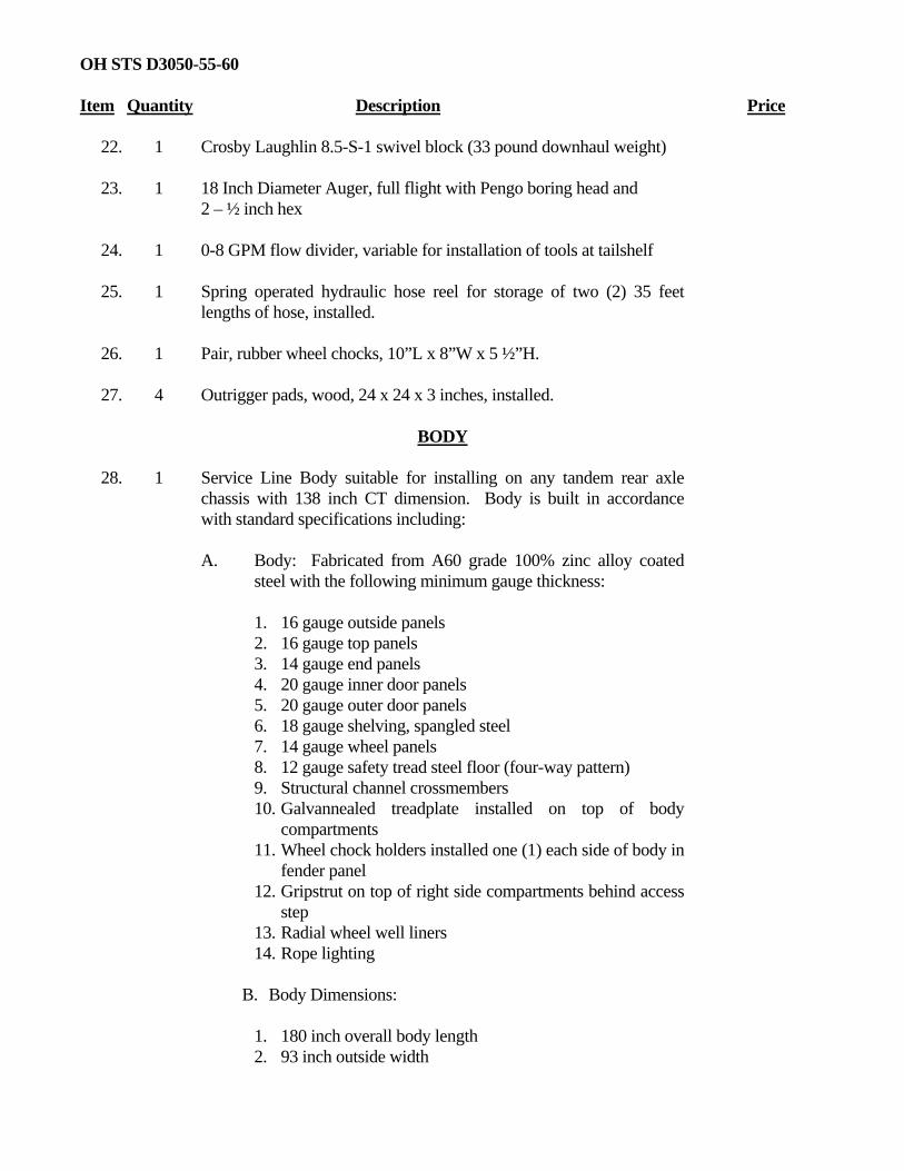
OH STS D3050-55-60 Item Quantity Description Price
22. 1 Crosby Laughlin 8.5-S-1 swivel block (33 pound downhaul weight)
23. 1 18 Inch Diameter Auger, full flight with Pengo boring head and 2 – ½ inch hex
24. 1 0-8 GPM flow divider, variable for installation of tools at tailshelf
25. 1 Spring operated hydraulic hose reel for storage of two (2) 35 feet lengths of hose, installed.
26. 1 Pair, rubber wheel chocks, 10”L x 8”W x 5 ½”H.
27. 4 Outrigger pads, wood, 24 x 24 x 3 inches, installed.
BODY
28. 1 Service Line Body suitable for installing on any tandem rear axle chassis with 138 inch CT dimension. Body is built in accordance with standard specifications including:
A. Body: Fabricated from A60 grade 100% zinc alloy coated steel with the following minimum gauge thickness:
1. 16 gauge outside panels 2. 16 gauge top panels 3. 14 gauge end panels 4. 20 gauge inner door panels 5. 20 gauge outer door panels 6. 18 gauge shelving, spangled steel 7. 14 gauge wheel panels 8. 12 gauge safety tread steel floor (four-way pattern) 9. Structural channel crossmembers 10. Galvannealed treadplate installed on top of body
compartments 11. Wheel chock holders installed one (1) each side of body in
fender panel 12. Gripstrut on top of right side compartments behind access
step 13. Radial wheel well liners 14. Rope lighting
B. Body Dimensions:
1. 180 inch overall body length 2. 93 inch outside width

OH STS D3050-55-60 Item Quantity Description Price
3. 46 inch body height 4. 18 inch compartment depth 5. 57 inch floor width
C. Compartmentation – Right Side:
1. First Vertical – Five (5) material hooks
2. Second Vertical – Access steps to cargo area (Treadplate) 3. Third Vertical – Three (3) material hooks 4. First Horizontal – Two (2) fixed shelves with removable
dividers on 8 inch centers 5. Second Horizontal - Two (2) fixed shelves with
removable dividers on 8 inch centers
D. Compartmentation – Left Side:
1. First Vertical – Three (3) adjustable shelves with removable dividers on 4 inch centers
2. Second Vertical – Five (5) material hooks 3. Third Vertical – Five (5) material hooks 4. First Horizontal – One (1) plain fixed shelf 5. Second Horizontal – One (1) plain fixed shelf 6. Through Shelf – Full length of left side of body with
hotstick brackets and rear door
E. Standard Features:
1. Basic body fabricated from A60 grade 100% zinc alloy coated steel
2. All doors are full, double paneled, self-sealed with built-in drainage for maximum weather-tightness. Electro-zinc plated, steel hinge rods extend full length of door. Door hinges are zinc alloy material attached with rivets.
3. All doors contain zinc plated flush type, single point paddle type locks with recessed handles, including keyed locks and adjustable two-stage strikers. Door handles are riveted to the outer door panel. Back panel has opening for easy access.
4. Heavy-gauge welded steel base construction with safety tread floor.
5. All edges are either rolled or folded for strength and safety 6. Door header drip rail at top for maximum weather
protection. 7. Neoprene fenders on wheel fender panels. 8. Steel treated for extra good primer bond and rust

OH STS D3050-55-60 Item Quantity Description Price
resistance 9. Automotive underseal applied to body. 10. Prime painted with two part epoxy. 11. Automotive type non-porous door seals mechanically
fastened to the door facing.
29. 1 Tailshelf, 24 inches includes light channels beneath tailshelf
30. 1 Steel rubber goods box, 75 inches long x 18 inches wide x 15 inches high, top opening. Includes wood lining, vents, gas props, and locking hasp.
31. 1 Steel ladder box installed on streetside compartment top. To include rear roller and strap.
32. 1 Cable suspended stirrup step installed at right side access steps
33. 2 Grab handles installed one each side at rear
34. 1 Grab handle installed at right side access steps
35. 1 Access step installed in cargo area at right side for access to right side compartment top
36. 1 Storage bracket for anchor auger on top of left side compartment
37. 1 Grab handle installed on front corner of riding seat console
38. 1 Grab handle installed at rear corner of riding seat console
39. 4 Outrigger pad holders installed under body.
40. 1 Storage bracket for the pole puller, installed on front outrigger leg.
41. 1 Soft copper reel rack (Altec P/N: 9700-86449), installed.
42. 1 Vise pocket plate and pocket installed at tailshelf extension. To include locking T-screw.
43. 1 Pole rack assembly on streetside of body. Rack to accommodate two (2) poles. Rear pole rack uprights to be installed so they don’t interfere with hotstick door or access to ladder rack. Front rack to have adjustable sliding collar. Rear pole rack to have bullet teeth and fixed uprights. Both racks to have nylon straps with hand ratchets.

OH STS D3050-55-60 Item Quantity Description Price
44. 1 Rope style compartment lights installed in each compartment. Wiring installed in loom with switch located in cab. Switch to be energized only when chassis lights are on.
45. 1 Derrick Storage Support
BODY ACCESSORIES
46. 1 T125 Pintle hook with frame reinforcement and two safety chain rings installed at 28 inches (+/- 1 inch) from ground to center of eye
47. 2 NuSteps installed one each side at rear
48. 2 D-Rings installed on rear of primary outriggers.
49. 1 (Set) splash aprons, installed behind rear wheels
50. 1 Triangular reflector kit installed in cab behind seat on passenger’s side
51. 2 Ten pound fire extinguisher with mounting bracket, shipped loose
52. 1 Rubber dock bumpers installed on right and left side of frame at rear
ELECTRICAL ACCESSORIES
53. 1 LED Lights and reflectors in accordance with FMVSS #108 lighting package, installed
54. 1 Electrical trailer connection installed
55. 2 LED Amber strobe light installed on each side of derrick storage support with master switch and indicator light installed in cab.
56. 1 Four corner LED strobe system: A) Two (2) amber strobe capsules installed in front turn signal
housings B) Two (2) 4” round amber strobes installed in rear light channel C) Master switch in cab
57. 1 Outrigger Motion Alarm: Provides audible alarm when any of the outriggers are in motion.
58. 1 Backup alarm, installed at rear. Backup alarm adjusts automatically to provide from 87 to 112 decibels alarm, depending on ambient noise

OH STS D3050-55-60 Item Quantity Description Price
conditions. Alarm is installed in 4.5 inch (114 mm) diameter hole with rubber grommet and is wired to chassis backup lights. Installation at rear provides a protected environment for alarm, free from damage from road spray and debris.
59. 1 Hour meter installed to record PTO operating hours
60. 1 Install Altec MP System for in-cab accessory switch panel. Includes dual lit switches for function identification and function activation.
INSTALLATION
61. 1 Installation of derrick and subbase assembly
62. 1 Installation of body and accessories
63. 1 Paint body White with urethane enamel
64. 1 Derrick painted white with the Altec Powder Coat Paint Process which provides a finish-painted surface that is highly resistant to chipping, scratching, abrasion and corrosion. Paint is electro-statically applied to the inside as well as outside of fabricated parts then high temperature cured prior to assembly ensuring maximum coverage and protection
65. 1 Non skid on all walking surfaces
66. 3 Three (3) Lev-O-Gage inclinometers. Two (2) installed each side at rear of tailshelf and one (1) at curbside of tailshelf.
67. 1 Safety and Instructional Signs, installed
68. 1 Vehicle height placard is to be placed in view of driver
69. 1 DOT Certification of completed vehicle
70. 1 Delivery of completed vehicle
MISCELLANEOUS
71. 1 This derrick is designed and manufactured in a facility that is certified to meet ISO 9001
72. 1 One (1) year parts warranty

OH STS D3050-55-60 Item Quantity Description Price
73. 1 One (1) year labor warranty
74. 1 Ninety (90) days warranty for travel charges
75. 1 For so long as the initial purchaser owns the product, major components warranty at an Altec service facility (See Altec Limited Warranty)
76. 1 Bidder is to supply a self-directed computer based training (CBT) program. This program will provide basic instruction in the safe operation of this aerial device. This program will also include and explain ANSI and OSHA requirements related to the proper use and operation of this unit.
LIST PRICE
164,600.00$
STATE DISCOUNT
14,964.00$
STATE PRICE
149,636.00$
RECOMMENDED CHASSIS
77. 1 CT: 138 inches
GVWR: 48,000 pounds FAWR: 14,000 pounds RAWR: 34,000 pounds See chassis specs, options, and pricing at end of Pricelist
OPTIONS
1. 1 Altec Model D3055A Hydraulic Derrick, designed for behind the cab or rear mount, built in accordance with Altec’s standard specifications and to include the following features: IN LIEU OF D3050. ADD…
654$
2. 1 Altec Model D3060A Hydraulic Derrick, designed for behind the cab or rear mount, built in accordance with Altec’s standard specifications and to include the following features: IN LIEU OF D3050. ADD…
1,307$

OH STS D3050-55-60 Item Quantity Description Price
3. 1 D4060A in lieu of D3060A, must pickup option for D3060 as well.
ADD…
5,695$
4. 1 D4050A in lieu of D3050A ADD…
$ 5,695
5. 1 #46 Radial auxiliary outriggers in lieu of the #47 three-stage outriggers. ADD… $ 1,435
6. 1 Hydraulically activated out and down outriggers in lieu of the “A” frame and radial outriggers. ADD… $ 5,182
7. 1 Rotation Interlock System. ADD….
$ 1,398
8. 1 #176 Platform use or combined Digger Derrick/Platform use. ADD…
300$
9. 1 #145 Platform – fiberglass pin-on, 24 x 24 x 42 inches, nominal, with interior/exterior platform access step, 300 pound capacity. ADD…
996$
10. 1 #150 Platform Cover – for single, one-man, side mounted fiberglass platform, nylon-reinforced vinyl, 24 x 24 inches. ADD…
54$
11. 1 #153 Platform Liner – for single, one-man, side mounted fiberglass platform, 24 x 24 x 42 inches, 50 Kv. ADD…
296$
12. 1 #168 Rear Mount – Traditional Control Seat, installed on curb side of turntable, includes single control station. IN LIEU OF OPTI-VIEW SEAT. DEDUCT…
(1,067)$
13. 1 #109 Joystick Control Panel, replaces selected control panel. Note: Joystick Control Panel replaces Traditional Control Seat. ADD…
1,109$
14. 1 Control Console with T-Stand in lieu of riding seat. ADD…
2,276$
15. 1 Swivel arm for T-Stand console. ADD…
1,047$
16. 1 Flip-up operator platform at tailshelf. ADD…
631$
17. 1 #039 Radio Remote Controls, lower controls. Note: Radio Remote Controls can be a stand alone system or can be used in conjunction with other control systems. ADD…
8,196$
18. 1 #118 Docking station for using main Radio Remote Control (Option 39) at boom tip for upper controls. ADD…
408$

OH STS D3050-55-60 Item Quantity Description Price
19. 1 #098 No hard wired upper controls, but with tool circuit at boom tip.
ADD…
671$
20. 1 #108 Four-Lever Upper Controls and Tool Circuit, transferable, including power package. Controls include:
(a) four (4) individual levers, for lift, rotation, sequential extension and winch functions
(b) one knob for on/off (blocking valve), including automatic two-speed throttle
(c) one knob for on/off of upper tool circuit and engine start/stop
ADD…
5,220$
21. 1 Steel sliding console covers for Opti-View control station. ADD…
598$
22. 1 #119 Jib – fiberglass, 4.8 foot material handling, two (2) piece telescopic, extends from 3.6 feet to 4.8 feet, manual articulation. ADD…
1,566$
23. 1 Jib storage bracket. ADD…
337$
24. 1 Braden Model AHSU10-12FEB Front Mounted Winch with heavy duty Braden Universal Bumper. ADD… A. 30,000-lbs. Capacity B. 4:1 extended shaft speed C. Extended shaft to right side D. Extend front frame rails as necessary for installation E. Extend front bumper and cover with treadplate F. Low Mount installation G. Hydraulic drive assembly for front winch including:
1. Two speed hydraulic motor 2. Hydraulic hoses and fittings 3. Installation including controls for winch forward/reverse
and two-speed in cab and at front extension H. (Set) flag holders installed on front bumper I. 4-way roller J. Storage box on street side K. Quick hook (wide-mouth type) L. 200’ of ½” diameter IWRC winch cable with loop sliced in
one end M. Winch guard upper and lower N. Vernier throttle at front extension
16,121$

OH STS D3050-55-60 Item Quantity Description Price
O. Wired for first gear hold P. Emergency stop/start
25. 1 Delete pole rack assembly and auxiliary boom saddle support. DEDUCT…
(1,581)$
26. 1 Astoria 138”CT fiberglass body in lieu of steel. Includes following features: ADD…
- Aluminum rock guards - Steel structural channel crossmembers - Spring loaded door holders on all vertical compartments - Vinyl coated chain on horizontal compartments - Drop in plastic tailboard at rear of body with aluminum
pockets - Aluminum treadplate riser, 6” up each side of cargo wall.
7,888$
27. 1 Aluminum tailshelf in lieu of steel. ADD…
121$
28. 1 Aluminum rubber goods box in lieu of steel. ADD…
190$
29. 1 Aluminum ladder box in lieu of steel. ADD…
266$
30. 4 Sauber aluminum outrigger pads in lieu of wood. ADD…
748$
31. 1 Recessed swivel D-Ring installed in cargo floor, each. ADD…
286$
32. 1 Hand coil rack consisting of upper and lower steel rails. Top rail to include 4 sliding ‘J’ hooks. Each rail approx 48”L. ADD…
617$
33. 1 Water cooler bracket, adjustable. ADD…
71$
34. 1 Hastings grounding reel with 50’ of 1/0 cable. Includes 3 point ground system with front and rear lugs. ADD…
3,529$
35. 1 Fifty feet (50’) of 1/0 copper cable, shipped loose. To include C-clamp on one end and Duckbill clamp on other end. Includes 3 point ground system with front and rear lugs. ADD…
1,072$
36. 1 Spotlight installed in chassis “A” pillar, each. ADD…
349$
37. 1 Unity combination spot/flood light, each. ADD…
355$
38. 1 Hayes electric brake controller. ADD…
463$

OH STS D3050-55-60 Item Quantity Description Price
39. 1 Star Beam dual bulb R/C spotlight (Altec p/n: 0684-35052). ADD…
1,097$
40. 2 TST Underbody lights. ADD…
384$
41. 1 12V DC power outlet, each. ADD…
270$
42. 1 Auxiliary start/stop at tailshelf. ADD…
263$
43. 1 Reverse floodlights installed under tailshelf along frame rails. To include master switch in cab and tie to ‘R’ function on automatic transmission if available. ADD…
332$
44. 1 Additional 4” round LED amber strobe, each. ADD…
297$
45. 1 1200W inverter with GFI receptacle installed at curbside rear. Note: Customer must order uprated alternator for proper inverter output. ADD…
1,514$
46. 1 Front bumper cone holder. Horizontal bar with pivot at curbside and locking pin at streetside. ADD…
599$
47. 1 Front bumper cone holder. Vertical storage with loops. ADD…
750$
48. 1 Rustproofing. ADD…
577$
49. 1 Custom color paint code (in lieu of standard white) for steel body, unit, and accessories. ADD…
1,028$
50. 1 Custom color gelcoat (in lieu of standard white) for Astoria Fiberglass body. ADD…
1,919$

Altec Industries, Inc.
March 1, 2013
OH STS Contract #7751501908
DM45/47/50 Digger Derrick (C3506) For 33k – 37k GVWR Chassis Application
45’/47’/50’ Sheave Height Hydraulic Digger Derrick – Flatbed T-Box
Item Quantity Description
UNIT
1. 1 Altec Model DM45 Hydraulic Derrick, Rear mount, designed for mounting over rear axle with a Turntable winch, built in accordance with Altec Industries standard specifications and to include the following features:
Maximum Sheave Height 44.4 ft
Maximum Horizontal Reach 35.0 ft
Maximum Digging Radius 24.8 ft
Elevation – From 80 degrees above horizontal to 20 degrees below horizontal
Performance Ranges per the attached capacity chart.
A. Unit meets or exceeds ANSI 10.31-1995. Unit serial number placard clearly states compliance.
B. Unit is designed and manufactured in facilities that are certified to
meet ISO 9001 requirements.
C. Winch: 15,000 pound bare drum capacity turntable winch with 8.625” diameter drum to comply with ANSI 10.31 Section 4.10.4 for synthetic rope or 15,000 pound bare drum capacity boom tip winch. High torque hydraulic motor drives a self-locking worm

50’ Digger Derrick with Flatbed Item Quantity Description
gear winch. Counterbalance valves on motor provide reliable load holding
D. Insulated, “46 kV and below”
E. Hydraulic Overload Protection System – activates when unit is
exposed to overload condition. System prevents actuation of all functions that could add to the overload condition including: - Boom Lower - Intermediate Boom Extend - Third Stage Boom Extend - Winch Raise - Auger Dig System automatically resets when overload condition is relieved.
F. Hydraulic Side Load Protection relieves overload conditions by allowing rotation system to back drive.
G. System pressure gauges on all vehicle mounted main control
stations.
H. Transferable Boom Flares include adjustable alignment guides.
I. Pole Guides – cylinder driven open/close and tilt includes double pilot operated check valves to support poles in both tilt directions. Also includes tilt interlock that prevents the upper boom from extending when the transferable flares are attached to the intermediate boom until the guides are articulated to the full up position.
J. Fiberglass Boom Tip with provisions for platform attachment.
K. Two-part load line attachment point on intermediate boom.
L. Full capacity fiberglass upper boom is round and is fabricated
using a Centrifically Cast process that provides a smooth surface finish inside and out that is easy to clean and is highly resistant to damage.
M. Cylinders: Rods are chrome plated and ends are threaded and
welded.
N. Bearings: Lift cylinder equipped with self-aligning bearings. All extending booms utilize slide bearings; there are no roller bearings on extending booms.

50’ Digger Derrick with Flatbed Item Quantity Description
O. Proportional-Hydraulic Control System: The electrical control panel(s) and pilot hydraulic system provide easy to operate controls with superior metering. There are only two hydraulic lines through rotation. Hydraulic control valves for Rotation, Boom Elevation, Boom Extension, Digger and Winch are pilot operated and controlled by a proportional pilot system which provides full metering and feathering characteristics. There are no hydraulic lines within operator control station.
P. Control system includes single quick connect plug for quick and
easy installation of radio remote control system in the field upon request.
Q. Standard/Low Speed Selector allows an operator to select
standard or low functional speeds without respect to engine throttle. When in standard mode, each function operates at normal speeds. When in low mode, the maximum operational speed of each function is approximately half that of the standard speed, providing a more meterable feel. The function is separate from engine throttle control, giving the operator additional fine tuning speed control.
R. Hydraulic Dump Valve installed in pedestal: Provides extra
protection by diverting hydraulic flow away from the main control valve when unit is idle. Dump valve solenoid is electronically activated when a function is operated.
S. Boom Storage Protection System – switch on main boom
activates hydraulic overload protection system to prevent operator from inadvertently placing excessive down force on boom stow bracket.
T. Continuous rotation including worm drive rotation gearbox. With
booms horizontal and fully extended, unit is able to rotate a 500 lbs load on winch line at boom tip up a 5 degree slope.
U. Manual Override of Hydraulic Functions at main control valve.
V. Complete Hydraulic System including:
1. Magnetic suction separator
2. Return line filter with cold oil indicator 3. Hydraulic pressure gauges
W. Outrigger/Boom Interlock System: Helps prevent operator from using unit until all outriggers are lowered.

50’ Digger Derrick with Flatbed Item Quantity Description
X. Outrigger/Unit Selector Control: Located near the outrigger
controls, allows operator to divert hydraulic oil from machine circuit for outrigger operation. This reduces the potential for inadvertent outrigger movement during machine operation if outrigger controls are bumped.
Y. Outrigger Control Valves, located at tailshelf
Z. Outrigger Motion Alarm: Provides audible alarm when any of the
outriggers are in motion.
AA. Back-up Alarm, installed
BB. Preventative Maintenance: Unit owner can select means of tracking maintenance intervals by calendar time or PTO hours. If the owner selects calendar driven cycles, preventative maintenance is required no more frequently than every 6 months. If the owner selects PTO hour driven cycles, preventative maintenance interval is likely to be greater than 6 months. Both programs allow the equipment owner to lower life cycle costs through higher product uptime and lower maintenance costs.
CC. Tool outlets at tailshelf – tool control valve is integral to the
outrigger control valve on the vehicle curbside.
DD. Two (2) Operator’s and Maintenance/Parts Manuals
EE. Painted white with Altec Powder Coat Paint Process which provides a finish-painted surface that is highly resistant to chipping, scratching, abrasion and corrosion. Paint is electro-statically applied to the inside as well as outside of all fabricated parts then high temperature cured prior to assembly ensuring maximum coverage and protection.
2. 1 #005 Rear Mount pedestal
3. 1 #008 Turntable Winch
4. 1 #011 Winch, normal speed (15,000 pounds)
5. 1 #175 Digger Derrick use only (no Personnel Handling)
6. 1 #168 Rear Mount – Traditional Control Seat, installed on curb side of
turntable, includes single control station

50’ Digger Derrick with Flatbed Item Quantity Description
7. 1 #031 Foot throttle
8. 1 #102 Cover – for standard Control Panel, vinyl
9. 1 No hard wired upper controls and no tool circuit at boom tip
10. 1 #088 Digger – right-hand storage – normal
11. 1 #094 Digger, Two-Speed Mechanical Shift, 12,000 ft-lbs, includes all of the components necessary to operate digger, installed
12. 1 #206 Auger assembly, 18 inch diameter, for 2 ½ inch kelly bar, carbide teeth
13. 1 #222 1 Inch x 115 feet – installed, 12,000 pound rating, for turntable winch
14. 1 #019 Swivel hook/downhaul weight, 5 ton capacity, 16 lbs.
15. 1 #044 Outriggers, A-frame, folding shoe, 153 inch maximum spread, for use as auxiliary outriggers only on DM units
16. 1 #450 Outriggers, A-frame, folding shoe, 153 inch maximum spread, for use as primary outriggers
17. 1 #501 Power Distribution Module, shipped loose. The Power Distribution Module is a compact self-contained electronic system that provides a standardized interface with the chassis electrical system. The Power Distribution Module (PDM) is composed of a main board, approximately 12.0 x 13.0 inches (305 x 330 mm), designed to be mounted behind the driver’s seat, inside the cab. Additional modules plug in to accommodate various options such as engine start/stop, variable throttle control, power take off, interface with Allison World transmission, and engine speed control module for specific engines and chassis. In addition to the above potential options, the PDM also provides up to 16 accessory circuits to be used for controlling other customer specified electrical components. The PDM includes built in test capabilities and diagnostic input, output and status LED’s to quickly assess the PDM’s performance. All components are circuit board mounted to facilitate replacement and reduce repair time should it be required. The PDM provides benefits to the customer by providing a standardized, centrally located box that greatly reduces troubleshooting time when evaluating ancillary electrical system malfunctions, thereby reducing maintenance costs, shipped loose.

50’ Digger Derrick with Flatbed Item Quantity Description
18. 1 No Electronic Side Load Protection – unit will be equipped with standard hydraulic side load protection
19. 1 No Altec RotaFloat System
20. 1 #077 Reservoir Assembly – includes 60 gallon reservoir, filter, and magnetic suction separator. Installed at front of flatbed.
21. 1 #060 Pole Puller – with 7 feet of 5/8 inch high-tensile chain and base
22. 1 Custom Option – pedestal through storage tunnel
UNIT AND HYDRAULIC ACCESSORIES
23. 1 Hydraulic pump – right-hand rotation, 14/21 @ 1,200 rpm, tandem vane
24. 1 (Set) Rubber wheel chocks, 10”L x 8”W x 5 ½”H.
25. 1 Hydraulic oil and lubricants, installed
26. 1 Cab control, heavy duty SAE PTO to be electronically engaged and disengaged.
27. 1 Subbase assembly for mounting of derrick pedestal and outriggers, to consist of 6 inch x 4 inch tubing (3/8 inch wall) each side of chassis frame with top and bottom plate. To include longitudinal storage with stops at 120”. Includes rear drop down door.
28. 1 Samson Nylite spool shield
29. 1 Auger wind up sling
30. 1 Stanley hydraulic tamp complete with three (3) feet of hose and quick disconnect couplings with three (3) foot handle
31. 1 (Set) of two 40 foot hydraulic hoses with two (2) quick disconnect couplings, dust caps, and fittings for hydraulic tool use installed on spring loaded reel at center rear of flatbed.
32. 1 0-8GPM flow divider, variable for installation of tools at tailshelf
33. Altec Braden PD18 Front Mounted Winch with heavy duty Braden Universal Bumper, including:
A. 20,000 pound capacity B. Extended shaft to curb side C. Hydraulic drive assembly for front winch, including:

50’ Digger Derrick with Flatbed Item Quantity Description
1. Control valve assembly, installation including controls for winch forward/reverse
2. Hydraulic hoses and fittings D. Winch controls installed at front extension E. 4-way roller F. Vernier throttle, installed G. IWRC 250’ of ½” diameter winch cable with loop
spliced in one end H. Storage box, installed at street side I. Tow eye J. Screw shackle K. Curved profile for International chassis L. Wired for auto neutral M. Winch guard upper and lower (for front winch)
BODY
34. 1 Altec 42” saddle compartment, for installation on any rear wheel
chassis with an 120”CA dimension, to include the following:
A. Body Features 1. Structural channel subbase 2. Treadplate installed on top of compartments 3. Rigid door holders on all body doors 4. Drip molding above and in front of all door openings 5. Full length rod-style hinges 6. Gang locks, installed one (1) each side of body 7. Automotive style rotary paddle latches 8. Automotive style bubble gasket door seals, installed
on all four (4) sides of door opening. 9. Rope lighting, installed on all three (3) sides of
compartment and wired to Altec’s standards
B. Body Dimensions
1. 42”length 2. 96” outside width 3. 46” height 4. 20”D compartment
C. Compartmentation- Street Side
Single compartment with double overlapping doors: 1. Eight (8) swivel material hooks mounted (2-4-2) as
high as possible in compartment. 2. Three (3) adjustable shelves with dividers on 4 inch
centers.
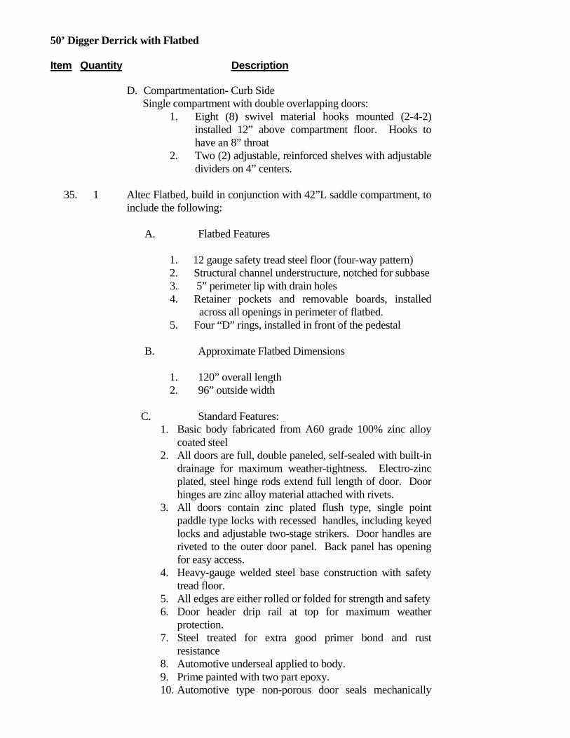
50’ Digger Derrick with Flatbed Item Quantity Description
D. Compartmentation- Curb Side Single compartment with double overlapping doors:
1. Eight (8) swivel material hooks mounted (2-4-2) installed 12” above compartment floor. Hooks to have an 8” throat
2. Two (2) adjustable, reinforced shelves with adjustable dividers on 4” centers.
35. 1 Altec Flatbed, build in conjunction with 42”L saddle compartment, to
include the following:
A. Flatbed Features
1. 12 gauge safety tread steel floor (four-way pattern) 2. Structural channel understructure, notched for subbase 3. 5” perimeter lip with drain holes 4. Retainer pockets and removable boards, installed
across all openings in perimeter of flatbed. 5. Four “D” rings, installed in front of the pedestal
B. Approximate Flatbed Dimensions
1. 120” overall length 2. 96” outside width
C. Standard Features:
1. Basic body fabricated from A60 grade 100% zinc alloy coated steel
2. All doors are full, double paneled, self-sealed with built-in drainage for maximum weather-tightness. Electro-zinc plated, steel hinge rods extend full length of door. Door hinges are zinc alloy material attached with rivets.
3. All doors contain zinc plated flush type, single point paddle type locks with recessed handles, including keyed locks and adjustable two-stage strikers. Door handles are riveted to the outer door panel. Back panel has opening for easy access.
4. Heavy-gauge welded steel base construction with safety tread floor.
5. All edges are either rolled or folded for strength and safety 6. Door header drip rail at top for maximum weather
protection. 7. Steel treated for extra good primer bond and rust
resistance 8. Automotive underseal applied to body. 9. Prime painted with two part epoxy. 10. Automotive type non-porous door seals mechanically

50’ Digger Derrick with Flatbed Item Quantity Description
fastened to the door facing.
35. 1 Punched metal mesh screen 12”H around top edge of transverse compartment
36. 1 Vertical ladder steps installed at right side of flatbed rear of T-Box.
37. 1 Grab handle installed at right side access steps
38. 1 Gripstrut step on side of flatbed edge to aid getting around control panel riding seat.
39. 2 Grab handles installed one each side of curbside rear access step.
40. 1 Vertically adjustable step installed on riding seat platform for access from flatbed.
41. 1 2 pole capacity pole rack installed on street side of flatbed.
42. 1 Storage bracket for the pole puller, installed on curbside outrigger leg.
43. 1 Cone holder, rear of flatbed.
44. 1 Rope style compartment lights installed in each compartment. Wiring installed in loom with switch located in cab. Switch to be energized only when chassis lights are on.
45. 1 Derrick Storage Support w/ offset for pole rack
BODY ACCESSORIES
46. 1 Pintle hook with frame reinforcement and two safety chain rings installed at 28 inches (+/- 1 inch) from ground to center of eye
47. 1 (Set) splash aprons, installed behind rear wheels
48. 1 E-Z Step installed at curbside rear corner of flatbed.
49. 1 Triangular reflector kit installed in cab behind seat on passenger’s side
50. 2 Ten pound fire extinguisher with mounting bracket, installed at front of body.
51. 1 Rubber dock bumpers installed on right and left side of frame at rear
52. 1 (Set) tow hooks installed at front of chassis

50’ Digger Derrick with Flatbed Item Quantity Description
53. 1 Through storage for 6 inch body cross members
ELECTRICAL ACCESSORIES
54. 1 LED Lights and reflectors in accordance with FMVSS #108 lighting package, installed
55. 1 Six way (6) electrical trailer connection installed
56. 2 LED Amber strobe light installed on street side of derrick storage support with master switch and indicator light installed in cab. Strobe light is to be visible from the front and rear of the vehicle.
57. 1 Hastings spring loaded grounding reel with 50’ of 2/0 cable, ferrule, and clamp, installed at rear of flatbed next to hose reel, paying out to the rear.
58. 1 3 Point grounding system, including front & rear grounding lugs.
59. 1 Post mounted spotlight installed on driver’s side
60. 2 Unity combination spot/flood lights. One installed on derrick storage support facing flatbed and one installed on rear of pedestal.
61. 1 Directional light bar installed at rear of flatbed.
62. 1 4 Corner LED Strobe System: A) Strobes in front turn signal housings B) Strobes installed in rear light channel C) Master switch on dash
63. 1 Outrigger Motion Alarm: Provides audible alarm when any of the outriggers are in motion.
64. 1 Backup alarm, installed at rear. Backup alarm adjusts automatically to provide from 87 to 112 decibels alarm, depending on ambient noise conditions. Alarm is installed in 4.5 inch (114 mm) diameter hole with rubber grommet and is wired to chassis backup lights. Installation at rear provides a protected environment for alarm, free from damage from road spray and debris.
65. 1 Hour meter installed to record PTO operating hours
66. 1 Install Altec MP System for in-cab accessory switch panel. Includes dual lit switches for function identification and function activation.

50’ Digger Derrick with Flatbed Item Quantity Description
INSTALLATION
67. 1 Installation of derrick and subbase assembly
68. 1 Installation of body and accessories
69. 1 Paint body White with urethane enamel
70. 1 Derrick painted white with the Altec Powder Coat Paint Process which provides a finish-painted surface that is highly resistant to chipping, scratching, abrasion and corrosion. Paint is electro-statically applied to the inside as well as outside of fabricated parts then high temperature cured prior to assembly ensuring maximum coverage and protection
71. 1 Safety and instructional signs, installed
72. 1 Vehicle height placard is to be placed in view of driver
73. 1 DOT Certification of completed vehicle
74. 1 Delivery of completed vehicle
MISCELLANEOUS
75. 1 This derrick is designed and manufactured in a facility that is certified to meet ISO 9001
76. 1 One (1) year parts warranty
77. 1 Ninety (90) days warranty for travel charges
78. 1 One (1) year labor warranty
79. 1 For so long as the initial purchaser owns the product, major components warranty at an Altec service facility (See Altec Limited Warranty)
79. 1 Bidder to supply a self-directed, computer based training (CBT) program. This program will provide basic instruction in the safe operation of this aerial device. This program will also include and explain ANSI and OSHA requirements related to the proper use and operation of this unit.
LIST PRICE 151,849.00$

50’ Digger Derrick with Flatbed Item Quantity Description
STATE DISCOUNT
13,805.00$
STATE PRICE
138,044.00$
RECOMMENDED CHASSIS
80. 1 120”CA 14,000-lb. FAWR 21,000-lb. RAWR 35,000-lb. GVWR See chassis specs, options, and pricing at end of Pricelist
OPTIONS
1. 1 Altec Model DM47 Hydraulic Derrick, Rear mount, designed for mounting over rear axle with a Turntable winch, built in accordance with Altec’s standard specifications. ADD…
1,601$
2. 1 DM50 in lieu of DM47, must order DM47 option. ADD…
7,917$
3. 1 Control console with T-Stand in lieu of riding seat. ADD…
2,276$
4. 1 Swivel arm for T-Stand console. ADD…
1,047$
5. 1 Flip-up operator platform at tailshelf. ADD…
631$
6. 1 #176 Platform use / combined Digger Derrick/Platform use. ADD…
300$
7. 1 #134 Altec Rota-Float : includes alarm and visual indicator. ADD…
1,142$
8. 1 #132 Altec Electronic Side Load Protection (eSLP)™ - includes indicator gauge and lamp. ADD…
1,322$
9. 1 #039 Radio Remote Controls, lower controls. Note: Radio Remote Controls can be a stand alone system or can be used in conjunction with other control systems. ADD…
8,196$
10. 1 #098 No hard wired upper controls, but with tool circuit at boom tip. ADD…
671$
11. 1 #118 Docking station for using main Radio Remote Control at boom 408$

50’ Digger Derrick with Flatbed Item Quantity Description
tip for upper controls. ADD…
12. 1 #145 Platform – fiberglass pin-on, 24 x 24 x 42 inches, nominal, with interior/exterior platform access step, 300 pound capacity. ADD…
996$
13. 1 #150 Platform Cover – for single, one-man, side mounted fiberglass platform, nylon-reinforced vinyl, 24 x 24 inches. ADD…
54$
14. 1 #153 Platform Liner – for single, one-man, side mounted fiberglass platform, 24 x 24 x 42 inches, 50 kV. ADD…
296$
15. 1 #152 Scuff pad, liner, 24 x 24 inches. ADD… 124$
16. 1 Transverse 1st vertical compartment with top opening lid.
1,151$
17. 1 Single doors for each compartment in lieu of double overlapping.
N/C

Altec Industries, Inc.
March 1, 2013
OH STS Contract #7751501908 DB37 Backyard Digger and Trailer
37’ Sheave Height Backyard Machine Item Quantity Description Price 1 Altec Model DB37 Hydraulic Derrick, designed for mounting on a
tracked carrier with a turntable winch, built in accordance with Altec’s standard specifications and to include the following features:
Maximum Sheave Height: 36.6 feet (without jib)
Maximum Sheave Height: 44.6 feet (with jib)
Maximum Horizontal Reach: 30.2 feet
Maximum Digging Radius: 19.5 feet
Elevation - From 75 degrees above horizontal to 6 degrees below horizontal
A. Outrigger Motion Alarm: Provides audible alarm when any of the
outriggers are being hydraulically actuated.
B. Digger, Single-Speed, fully proportional, 2,500 ft-lbs (3390 N-m) - includes all of the components necessary to operate digger (installed)
C. Auger assembly, 18 inch (457 mm) diameter, for 2 inch (51 mm)
kelly bar, carbide teeth
D. Rope, material handling, 1/2 inch x 80 feet (13 mm x 24.4 m) - installed, 3,000 pounds (1361 kg) rating. Includes eyes at both ends.
E. Outrigger/boom interlock system, prevents operation of unit until all
outriggers are down.
F. Swivel hook/downhaul weight, 1 1/2 ton (1.4 t) capacity.

G. Digger Derrick Conforms to ANSI A10.31-1995
H. Insulated, "46 kV and below"
I. Pendant drive controls installed.
1. 1 #410 Trailer - 10,000 pound GVWR includes wheel chock holders and
tie down straps.
2. 1 #121 Jib - fiberglass, 8 foot (2.4 m) material handling, one (1) piece, manual articulation accomplished utilizing five (5) pinning positions. Includes boom mounting bracket and hardware, pins, and trailer brackets.
3. 1 #145 Platform - fiberglass pin-on, 24 x 24 x 42 inches (610 x 610 x 1067 mm), nominal, with interior/exterior platform access step, 300 pound capacity (136 kg) (See Note #1) - price is per platform and includes unit mounting bracket and trailer tie down strap. Note: requires radio remote controls and docking station.
4. 1 #150 Platform Cover - for single, one-man, side mounted fiberglass platform, nylon-reinforced vinyl, 24 x 24 inches (610 x 610 mm)
5. 1 #39 Radio Remote Controls, installed, Operate all Digger Derrick functions
6. 1 #118 Docking station for use with Radio Remote Control at boom tip for upper controls
7. 1 #113 Pole guide, manual tilt
8. 1 #400 Pole Carrier, bracket mounted to carrier - maximum weight rating of 2,000 pounds (907 kg)
9. 1 #420 Cargo Platform, fold out - maximum weight rating of 1,300 pounds (590 kg)
10. 1 #297 Tools below rotation - one set of quick disconnect tool outlets
11. 1 #411 Outrigger pads, set of 4, wood, 18 x 18 x 3 inch
12. 1 #155 Fall Protection System to include one body harness and decelerating type lanyard. Harness has adjustable slide buckle on shoulder straps, Velcro chest strap, interlocking buckles on leg straps and nylon web loop fall arrest attachment on back. Lanyard has built in shock absorber that allows 28 inches (711 mm) of automatic adjustability. (See Note #1)
UNIT AND HYDRAULIC ACCESSORIES

1. 1 Hydraulic oil and lubricants, installed
2. 1 Substructure for mounting of derrick pedestal and outriggers to carrier.
3. 1 Derrick Boom Storage Support
INSTALLATION
1. 1 Installation of derrick and subbase assembly
2. 1 Derrick painted white with the Altec Powder Coat Paint Process which
provides a finish-painted surface that is highly resistant to chipping, scratching, abrasion and corrosion. Paint is electro-statically applied to the inside as well as outside of fabricated parts then high temperature cured prior to assembly ensuring maximum coverage and protection
3. 1 Safety and instructional signs, installed
MISCELLANEOUS
1. 1 This derrick is designed and manufactured in a facility that is certified to meet ISO 9001
2. 1 One (1) year parts and labor warranty. Ninety (90) days warranty for travel charges.
3. 1 Delivery of completed vehicle
CARRIER
1. 1 Tracked Carrier Diesel engine and direct drive pump provide hydraulic power for carrier and unit operation. Fuel tank, installed, 12 gallon (45 l) capacity.
LIST PRICE
157,599.00$
STATE DISCOUNT
14,327.00$
STATE PRICE
143,272.00$

Altec Industries, Inc.
We Wish To Thank You For Giving Us The Pleasure
And Opportunity of Serving You UTILITY EQUIPMENT AND BODIES SINCE 1929
Page 1 of 2
March 1, 2013
OH STS Contract #7751501908 Fiberglass Service Body
For 60”CA Chassis Application Item Description Qty Price
Body
1. Brand FX model BFXB 60LS Series Service body designed for mounting on cab and chassis with extended cab, 60 inch CA. 108 inches long. 94 inches wide. 54 inch floor width. 42 inch height. 20 inch compartment depth. -Aluminum understructure. -Aluminum treadplate on cargo floor, walls and compartment tops. -Stainless steel hinges, latches and hardware. Latches shall be recessed paddle type. -All doors to have rubber seals and door holders. -Three adjustable shelves in the vertical compartments and one adjustable shelf in the horizontal compartments. Shelves to have removable dividers. -Yellow gelcoat to match chassis, Ford W-6695.
1
2. Service Body -Aluminum tailshelf, 30 inches with streetside and curbside access to
cargo area with steps and handrails. -LED lights mounted into tailshelf as follows: All to be round, grommet mounted, 4 inch LED, pigtail and Deutsch connector. Two outer lights, each side, red Brake/Turn/Tail. One inner light, each side, clear Backup. Rope style compartment lights. -Aluminum ladder rack mounted on top of curbside compartment. Mud flaps installed behind rear wheels
1
3. Delivery Of Completed Unit 1
LIST PRICE
$16,262
STATE DISCOUNT
($1,477)
STATE PRICE
$14,785

Altec Industries, Inc.
We Wish To Thank You For Giving Us The Pleasure
And Opportunity of Serving You UTILITY EQUIPMENT AND BODIES SINCE 1929
Page 2 of 2
ADDITIONAL OPTIONS
Additional Option 1 -Class III receiver hitch with 2 inch safety chain loops. -Round 7 pole trailer receptacle with round pins. ADD……
1 $530
Additional Option 2 -Rear warning lights to include round 4 inch amber LED, pigtail and
Deutsch connector, grommet mounted into upper rear of the streetside and curbside compartments, controlled by switch in cab. ADD…..
1 $725
Additional Option 3 -Backup alam. ADD….. 1 $135
Additional Option 4 -Two post mounted spotlights in chassis cab, one in driver side
post and one in passenger side post. ADD…. 1 $495
Additional Option 5 -1200 watt inverter, location TBD, with curbside rear GFI
receptacle. ADD….
1 $1,514
Additional Option 6 -2400 watt inverter, location TBD, with curbside rear GFI receptacle. ADD…..
1 $2,756

Altec Industries, Inc.
March 1, 2013
OH STS Contract #7751501908 Common Options List
For applicable Aerial Devices and Digger Derricks Item Quantity Description Price
1. 1 Recessed swivel D-Ring, ADD…
286$
2. 1 Standard D-Ring (non-recessed), each. ADD…
179$
3. 1 Water cooler bracket. ADD…
71$
4. 1 Buckingham ergonomic harness/lanyard. ADD…
238$
5. 1 Three point ground system with front and rear lugs. ADD…
829$
6. 1 Hastings spring loaded grounding reel with 50’ of 1/0 cable, includes three point ground system with front and rear lugs. ADD…
3,529$
7. 1 Hastings spring loaded grounding reel with 50’ of 2/0 cable, includes three point ground system with front and rear lugs. ADD…
3,710$
8. 1 50’ of 1/0 grounding cable (loose), three point ground system, front and rear ground lugs. ADD…
1,072$
9. 1 Hannay spring loaded grounding reel with 50’ of 1/0 cable, includes three point ground system with front and rear lugs. ADD…
1,829$
10. 1 Post mount spotlight for chassis ‘A’ pillar, ADD…
349$
11. 1 Unity combination spot/flood light, ADD…
355$

Common Options List Item Quantity Description Price
12. 1 Electric brake controller, ADD…
462$
13. 2 TST Underbody Lights. ADD…
384$
14. 1 Streamlight with vehicle mounted holder/charger. ADD…
432$
15. 1 GoLight remote control light with dash mounted controller. ADD…
462$
16. 1 NiteRay spot/flood remote control light with dash mounted control. ADD…
664$
17. 1 Reverse/Work floodlights installed under tailshelf. ADD…
332$
18. 1 LED cargo wall light, each. ADD…
263$
19. 1 Additional 4” round LED strobe. ADD…
$ 303
20. 1 My Mobile Vision, SM7-127-1087 KIT, back up camera system. ADD…
$ 1,050
21. 1 Back up sensor, only, installed. ADD…
$ 405
22. 1 1200W inverter with one (1) weatherproof GFI recepctacle. ADD…
$ 1,514
23. 1 2400W inverter with one (1) weatherproof GFI recepctacle. ADD…
$ 2,756
24. 1 Additional weatherproof GFI receptacle. ADD…
$ 171
25. 1 12V DC power outlet, each. ADD…
$ 270
26. 1 Auxiliary throttle control switch (when applicable). ADD…
$ 263
27. 1 Auxiliary start/stop with emergency power (when auxiliary pump is applicable). ADD…
$ 263
28. 1 Electric rear mount capstan, 1000 lb. capacity, w/ capstan head. ADD…
$ 3,050
29. 1 Soft copper reel rack (holds up to 4 reels). Capable of removing individual reels without removing all reels. ADD…
$ 662
30. 1 Hand coil rack assembly with sliding hooks. ADD…
$ 617
31. 1 Horizontal front bumper cone holder with pivot arm and keeper $ 500

Common Options List Item Quantity Description Price
tab. ADD…
32. 1 Vertical front bumper cone holder loops with drop down feature. ADD…
$ 750
33. 1 PVC tube (75”L) with aluminum end caps, each. ADD…
617$
34. 1 Aircraft Dynamics Roboreel Universal Guy Stand – Curbside installation. ADD…
$ 750
35. 1 Aircraft Dynamics Roboreel Universal Guy Stand – Streetside installation. ADD…
$ 750
36. 1 Aircraft Dynamics Roboreel – Triplex. ADD…
$ 864
37. 1 Post type cone holder. ADD…
$ 212
38. 1 Removable vise bracket with pocket assembly and locking ‘T’ screw. ADD…
$ 234
39. 1 Removable cone holder bracket with pocket and locking ‘T’ screw. ADD…
$ 288
40. 1 Wilton 6” vise. ADD…
212$
41. 1 Universal transformer bracket. ADD…
$ 385
42. 1 Slide-N-Lock rail assembly (up to 60”L), each. ADD…
$ 356
43. 1 EZ-Step pull out access step in lieu of NuStep hose step. ADD…
$ 241
44. 1 Transverse tailshelf storage with drop down doors each side (when applicable). ADD…
$ 569
45. 1 Panned in storage area between frame rails with mesh bottom and drop down door (when applicable). ADD…
$ 697
46. 1 Cargo access walkway in curbside of tailshelf in lieu of side of body. ADD…..
$ 325
47. 1 Customer specified color code for steel portions of build in lieu of standard white. ADD…
$ 1,078
48. 1 Rustproofing. ADD…
569$
49. 1 Rotafloat screw anchor installation system (diggers only). ADD…
$ 1,142

Common Options List Item Quantity Description Price
50. 1 eSLP electronic side load protection (for diggers only). ADD…
$ 1,322
51. 1 Altec Braden PD18 Front Mounted Winch with heavy duty Braden Universal Bumper. ADD… INCLUDES:
20,000 pound capacity Extended shaft to curb side Hydraulic drive assembly for front winch, including:
Electric-over-hydraulic controls for winch forward and reverse
Winch controls installed at front extension and in cab on dash (toggle switch).
6) 4-way roller 7) Two speed throttle, installed 8) 250' of 1/2" cable installed 9) Storage box, installed at street side 10) Tow eye 11) Screw shackle 12) Curved profile for chassis 13) Wired for first gear hold 14) Emergency stop switch at front controls 15) Orange sight rods, installed.
NOTE: This option typically requires a an upgraded front axle
$ 10,730
52. 1 Hydraulic rear mount capstan, 4,000 lb capacity, with capstan head. ADD…..
$ 6,100
53. 1 Hybrid prep package for applicable PERSONNEL ONLY aerial devices. For use with Eaton ePTO hybrid power systems. ADD…
$ 9,866
54. 1 Hybid prep package for applicable MATERIAL HANDLER aerial devices. For use with Eaton ePTO hybrid power systems. ADD…
$ 10,522
55. 1 Remote mounted PEC. Required when hybrid batteries are not mounted on frame rail under extended cab chassis have to be relocated in body. ADD…
1,322$

Altec Industries, Inc.
March 1, 2013
OH STS Contract #7751501908 Ford F-550 Chassis
NOTE: Chassis’ are not for individual sale – all chassis orders must be in conjunction with unit/body order.
Item Quantity Description Price
CHASSIS 1. 1 2013 (or newer) F-550 4x2 Cab and Chassis
CA – 60 inches GVWR 18,000 lbs. FAWR 7,000 lbs. with 6,500lb springs RAWR 13,660 lbs. with 13,660 springs and 900lb auxiliary 4.10 rear axle ratio Diesel Engine - 6.7L V8; 300 hp @ 2,800 rpm; 660 lb.-ft. @ 1,600 rpm Transmission six speed electronic shift w/ OD and PTO provision Fuel tank: 40 gallon tank mounted aft of rear axle Snowplow prep package XL Décor Package Power steering with super engine cooling package Hydraulic disc brakes with 4 wheel ABS Intermittent wipers Front tow hooks Engine block heater Standard Gauge Package Dash mounted engine hour-meter 200 AMP alternator Dual maintenance free batteries (750CCA) Telescoping manual trailer tow mirrors LT225/70R/19.5F traction tread radial tires - front and rear. A/C Heater/Defroster Bench split seat (40/20/40) Dual sun visors Tinted glass Cigarette lighter

OH STS Ford F-550 Chassis Item Quantity Description Price
Auxiliary power point Tilt column steering wheel AM/FM Stereo Radio Z1 Oxford White exterior paint
LIST PRICE
$36,350
STATE DISCOUNT
($760)
STATE PRICE
$35,590
OPTIONS
1. 1 84”CA in lieu of 60”CA, ADD…
$213
2. 1 19,000GVWR in lieu of 17,950 (Must order Option #1) ADD…
$1,155
3. 1 4x4 in lieu of 4x2, ADD…
$4,281
4. 1 Triton V-10 gas engine in lieu of the 6.7L diesel engine, DEDUCT…
($5,795)
5. 1 Limited slip rear axle (for 4x2 chassis), ADD…
$360
6. 1 Manual transmission (This option is no longer available, automatic transmission only is available)
Not Available
7. 1 Super Cab in lieu of standard cab (when applicable) ADD…
$2,485
8. 1 Crew Cab in lieu of standard cab (when applicable) ADD…
$3,481
9. 1 Running boards, ADD…
$320
10. 1 Vinyl bucket seats in lieu of vinyl bench seat, ADD…
$355
11. 1 Power Equipment Group; Includes: Power Locks, Power Front Side Windows, Includes driver side 1-touch down and accessory delay, Trailer Tow Mirrors w/Power Heated Glass, Includes manual telescoping and integrated clearance lights/turn signals). ADD…
$895
12. 1 Standard Ford exterior color other than white
N/C

Altec Industries, Inc.
March 1, 2013
OH STS Contract #7751501908
Dodge 5500 Chassis 60”CA
NOTE: Chassis’ are not for individual sale – all chassis orders must be in conjunction with unit/body order. Item Quantity Description Price
CHASSIS 1. 1 2013 (or newer) Dodge 5500 4x2 Cab and Chassis
CA – 60 inches GVWR 18,750 lbs. FAWR 7,000 lbs. RAWR 13,500 lbs. Cummins Diesel Engine - 6.7L 305 HP Transmission, six speed, manual with PTO provision. Fuel tank: 52 gallon tank mounted aft of rear axle ST Package Power steering with super engine cooling package Hydraulic disc brakes with 4 wheel ABS Variable intermittent wipers Front tow hooks Engine block heater 136 amp alternator Standard Gauge Package AM/FM/CD Radio – Satellite Ready Dual front airbags with passenger cancel Dual maintenance free batteries Telescoping manual trailer tow mirrors 225/70R/19.5F (traction tread all around) A/C Heater/Defroster Vinyl 40/20/40 split bench seat Dual sun visors Tinted glass
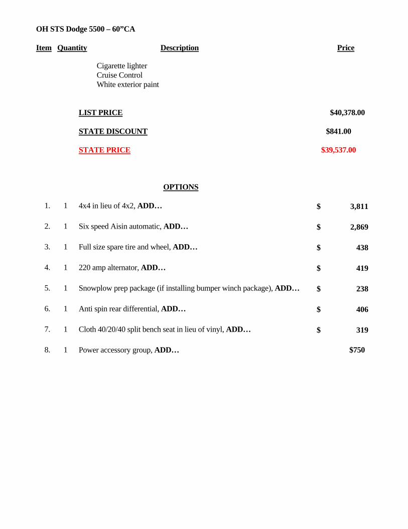
OH STS Dodge 5500 – 60”CA Item Quantity Description Price
Cigarette lighter Cruise Control White exterior paint
LIST PRICE
$40,378.00
STATE DISCOUNT
$841.00
STATE PRICE
$39,537.00
OPTIONS
1. 1 4x4 in lieu of 4x2, ADD…
3,811$
2. 1 Six speed Aisin automatic, ADD…
2,869$
3. 1 Full size spare tire and wheel, ADD…
438$
4. 1 220 amp alternator, ADD… 419$
5. 1 Snowplow prep package (if installing bumper winch package), ADD…
238$
6. 1 Anti spin rear differential, ADD…
406$
7. 1 Cloth 40/20/40 split bench seat in lieu of vinyl, ADD…
319$
8. 1 Power accessory group, ADD…
$750

Altec Industries, Inc.
March 1, 2013
OH STS Contract #7751501908
Dodge 5500 Chassis 84”CA
NOTE: Chassis’ are not for individual sale – all chassis orders must be in conjunction with unit/body order. Item Quantity Description Price
CHASSIS 1. 1 2013 (or newer) Dodge 5500 4x2 Cab and Chassis
CA – 84 inches GVWR 19,500 lbs. FAWR 7,000 lbs. RAWR 13,500 lbs. Cummins Diesel Engine - 6.7L 305 HP 50 state emission Transmission, six speed, manual with PTO provision. Fuel tank: 52 gallon tank mounted aft of rear axle ST Package Power steering with super engine cooling package Hydraulic disc brakes with 4 wheel ABS Variable intermittent wipers Front tow hooks Engine block heater 136 amp alternator Standard Gauge Package AM/FM/CD Radio – Satellite Ready Dual front airbags with passenger cancel Dual maintenance free batteries Telescoping manual trailer tow mirrors 225/70R/19.5F (traction tread all around) A/C Heater/Defroster Vinyl 40/20/40 split bench seat Dual sun visors Tinted glass Cigarette lighter

OH STS Dodge 5500 – 84”CA Item Quantity Description Price
Cruise Control White exterior paint
LIST PRICE
$40,745.00
STATE DISCOUNT
$849.00
STATE PRICE
$39,896.00
OPTIONS
1. 1 4x4 in lieu of 4x2, ADD…
3,811$
2. 1 Six speed Aisin automatic, ADD…
2,869$
3. 1 Full size spare tire and wheel, ADD…
438$
4. 1 220 amp alternator, ADD… 419$
5. 1 Snowplow prep package (if installing bumper winch package), ADD…
238$
6. 1 Anti spin rear differential, ADD…
406$
7. 1 Cloth 40/20/40 split bench seat in lieu of vinyl, ADD…
319$
8. 1 Power accessory group, ADD…
$750.00

Altec Industries, Inc.
March 1, 2013
OH STS Contract #7751501908
Ford F-750 4x2 Chassis NOTE: Chassis’ are not for individual sale – all chassis orders must be in conjunction with unit/body order.
Item Quantity Description Price
CHASSIS 1. 1 2013 (or newer) F-750 4x2 cab and chassis
84”CA 12,000-lb. FAWR 21,000-lb. RAWR 33,000-lb. GVWR Transmission: Allison 3000RDS, 5 speed automatic transmission, close ratio Cummins ISB Diesel Engine: 240 HP Horizontal exhaust Fuel tank, 50 gallon, mounted under cab Exterior Color: white Front axle: 12,000 lb. I-beam type. Rear axle: 21,000 Dana Spicer 21060S Front suspension: 12,000lb spring parabolic, taper leaf. Rear suspension: 23,500 lb. Rear axle ratio: 5.57 Conventional steel cab Fiberglass tilting front end Front tires- (2) Hankook AH12 (or equivalent) Rear tires- (4) Hankook DL01 (or equivalent) Dual air brake system Front and rear automatic slack adjusters Air dryer with heater Air compressor- 13.2 CFM Auto moisture ejectors Tilting steering column 12-volt electrical system Vinyl bench seat

OH STS Ford F-750 Chassis Item Quantity Description Price
Intermittent windshield wipers Cigar lighter 130 amp alternator Battery system- Total of 2, temporary mounted. AM/FM radio Air horn Halogen headlights Engine block heater Cruise Control Auxiliary power point on dash Exterior grab handle XL Décor Driver seat, fixed, high back with integral headrest Two-man high intermediate back passenger seat, integrated headrest in both occupant positions Break-away mirrors, West coast style with convex spots Air conditioner with heater and defroster Deluxe trim
STATE PRICE
57,158.00$
STATE DISCOUNT
1,191.00$
STATE PRICE
55,967.00$
OPTIONS
1. 1 102”CA in lieu of 84”CA
N/C
2. 1 108”CA in lieu of 84’CA, ADD…
88$
3. 1 120”CA in lieu of 84”CA, ADD…
(125)$
4. 1 Driver controlled locking differential. ADD…
1,875$
5. 1 Super cab in lieu of standard cab (when applicable). ADD…
2,019$
6. 1 Crew cab in lieu of standard cab (when applicable). ADD…
4,781$
7. 1 260HP in lieu of 240HP. ADD…
1,463$
8. 1 300HP in lieu of 240HP. ADD… 2,288$
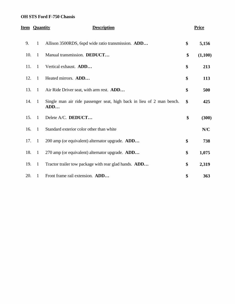
OH STS Ford F-750 Chassis Item Quantity Description Price
9. 1 Allison 3500RDS, 6spd wide ratio transmission. ADD…
5,156$
10. 1 Manual transmission. DEDUCT…
(1,100)$
11. 1 Vertical exhaust. ADD…
213$
12. 1 Heated mirrors. ADD…
113$
13. 1 Air Ride Driver seat, with arm rest. ADD…
500$
14. 1 Single man air ride passenger seat, high back in lieu of 2 man bench. ADD…
425$
15. 1 Delete A/C. DEDUCT…
(300)$
16. 1 Standard exterior color other than white
N/C
17. 1 200 amp (or equivalent) alternator upgrade. ADD…
738$
18. 1 270 amp (or equivalent) alternator upgrade. ADD…
1,075$
19. 1 Tractor trailer tow package with rear glad hands. ADD…
2,319$
20. 1 Front frame rail extension. ADD…
363$

Altec Industries, Inc.
March 1, 2013
OH STS Contract #7751501908
Freightliner M2 33k-37k GVWR 4x2 Chassis NOTE: Chassis’ are not for individual sale – all chassis orders must be in conjunction with unit/body order.
Item Quantity Description Price
CHASSIS 1. 1 2013 (or newer) M2 4x2 cab and chassis
84”CA 12,000-lb. FAWR 21,000-lb. RAWR 33,000-lb. GVWR Transmission: Allison 3000RDS, 5 speed automatic transmission, Cummins Diesel Engine: 240HP/620lb-ft Vertical exhaust Front suspension: 14,600lb Rear suspension: 23,000lb Fuel tank, 50 gallon, mounted under cab LH Exterior Color: White Conventional aluminum cab Fiberglass tilting front end Front tires- (2) G149 or equivalent Rear tires- (4) G177 or equivalent Dual air brake system Remote engine throttle control Electric brake controller provision Front and rear automatic slack adjusters Air dryer with heater Air compressor- 13.2 CFM Auto moisture ejectors Tilting and telescoping steering column 12-volt electrical system Vinyl bench seat Intermittent windshield wipers Cigar lighter 160 amp alternator

OH STS Freightliner M2 33k-37k GWVR Chassis Item Quantity Description Price
Battery system- Total of 2 with 2200CCA AM/FM radio Air horn Halogen headlights Cruise Control Auxiliary power point on dash Engine block heater Driver seat, fixed, high back with integral headrest Two-man high back passenger seat, integrated headrest in both occupant positions Break-away mirrors, West coast style with convex spots Air conditioner with heater and defroster Deluxe trim
LIST PRICE
67,342.00$
STATE DISCOUNT
1,403.00$
STATE PRICE
65,939.00$
OPTIONS
1. 1 102”CA in lieu of 84”CA. ADD…
156$
2. 1 108”CA in lieu of 84’CA. ADD…
156$
3. 1 120”CA in lieu of 84”CA. ADD…
448$
4. 1 ¼” C Channel Frame Insert. ADD…
926$
5. 1 33,000lb GVWR (13,000lbFA and 20,000lb RA).
N/C
6. 1 35,000lb GVWR (14,000lb FA and 21,000lb RA). ADD…
1,404$
7. 1 35,000lb GVWR (12,000lb FA and 23,000lb RA). ADD…
486$
8. 1 37,000lb GVWR (14,000lb FA and 23,000lb RA). ADD…
1,148$
9. 1 Driver controlled locking differential. ADD…
518$
10. 1 Extended cab in lieu of standard cab. ADD…
5,446$

OH STS Freightliner M2 33k-37k GWVR Chassis Item Quantity Description Price
11. 1 Crew cab in lieu of standard cab. ADD…
9,346$
12. 1 Cummins 260HP/620lb-ft in lieu of 240HP. ADD… 5,525$
13. 1 Cummins 260HP/800lb-ft in lieu of 240HP. ADD…
5,948$
14. 1 Cummins 285HP/800lb-ft in lieu of 240HP. ADD…
6,773$
15. 1 Allison 3500RDS, 6 speed automatic transmission, close ratio. ADD…
211$
16. 1 Manual transmission. DEDUCT…
(4,309)$
17. 1 Horizontal exhaust in lieu of vertical. DEDUCT…
(308)$
18. 1 Heated mirrors. ADD…
113$
19. 1 Power windows and locks. ADD…
219$
20. 1 Bench seat. DEDUCT…
(77)$
21. 1 Air Ride Driver seat, with arm rest. ADD…
259$
22. 1 Single man air ride passenger seat, high back in lieu of 2 man bench. ADD…
341$
23. 1 Delete A/C. DEDUCT…
(472)$
24. 1 Standard exterior color other than white. ADD…
240$
25. 1 Custom exterior color other than white. ADD…
981$
26. 1 Exterior grab handle, each. ADD…
59$
27. 1 200 amp (or equivalent) alternator upgrade. ADD…
374$
28. 1 270 amp (or equivalent) alternator upgrade. ADD…
696$
29. 1 Tractor trailer towing package with rear glad hands. ADD…
670$
30. 1 Front frame rail extension (delete front bumper). ADD…
1,938$
31. 1 Two way radio wiring effects. ADD… 76$

OH STS Freightliner M2 33k-37k GWVR Chassis Item Quantity Description Price

Altec Industries, Inc.
March 1, 2013
OH STS Contract #7751501908
International DuraStar 4300 (25,999GVWR) 4x2 Chassis
NOTE: Chassis’ are not for individual sale – all chassis orders must be in conjunction with unit/body order.
Item Quantity Description Price
CHASSIS 1. 1 2013 (or newer) 4300 4x2 cab and chassis
91”CA (vertical exhaust, 84” usable) 10,000-lb. FAWR 19,000-lb. RAWR 25,999-lb. GVWR Transmission: Allison 3000RDS, 5 speed automatic transmission, close ratio MaxxForce 7 Engine: 230 HP / 620 ft-lbs Vertical exhaust Fuel tank, 50 gallon, mounted under cab Exterior Color: 9219 winter white Front axle: 12,000 lb. I-beam type Rear axle: 19,000 lb, single reduction. Front suspension: spring parabolic, taper leaf. Rear suspension: 19,000 lb. Conventional steel cab Fiberglass tilting front end Front tires- (2) G149 or equivalent Rear tires- (4) G177 or equivalent Dual air brake system Manual reset circuit breakers with trip indicators Remote engine throttle control Front and rear automatic slack adjusters Air dryer with heater Air compressor- 13.2 CFM Auto moisture ejectors Tilting steering column 12-volt electrical system

OH STS International 4300 (25,999GVWR) Chassis Item Quantity Description Price
Intermittent windshield wipers Cigar lighter 140 amp alternator Battery system- Total of 3 with 1950CCA AM/FM radio Air horn Cruise Control Halogen headlights Engine block heater Driver seat, fixed, high back with integral headrest Two-man high back passenger seat, integrated headrest in both occupant positions Break-away mirrors, West coast style with convex spots Air conditioner with heater and defroster Deluxe trim
LIST PRICE
72,146.00$
STATE DISCOUNT
1,503.00$
STATE PRICE
70,643.00$
OPTIONS
1. 1 102”CA in lieu of 84”CA.
N/C
2. 1 108”CA in lieu of 84’CA.
N/C
3. 1 120”CA in lieu of 84”CA, ADD…
N/C
4. 1 25,999lb GVWR (12,000lb FA and 19,000lb RA), ADD…
331$
5. 1 Extended cab (26”) with rear bench seat (Minimum requirements are horizontal exhaust, single man passenger seat, 197”WB for 84”C usable CA) ADD…
3,161$
6. 1 Extended cab (26”) without rear bench seat (Minimum requirements are horizontal exhaust, single man passenger seat, 197”WB for 84”C usable CA) ADD…
2,786$
7. 1 Crew cab with rear bench seat (Minimum requirements are horizontal exhaust, single man passenger seat, 197”WB for 84”C usable CA) ADD…
7,576$

OH STS International 4300 (25,999GVWR) Chassis Item Quantity Description Price
8. 1 Crew cab without rear bench seat (Minimum requirements are horizontal exhaust, single man passenger seat, 197”WB for 84”C usable CA) ADD…
7,201$
9. 1 Manual transmission, DEDUCT…
(5,152)$
10. 1 Horizontal exhaust in lieu of vertical (102”CA or 169”WB and up). DEDUCT…
(317)$
11. 1 Heated mirrors, ADD…
68$
12. 1 Power windows, ADD…
303$
13. 1 Air Ride Driver seat, with arm rest, ADD…
195$
14. 1 Single man air ride passenger seat, high back in lieu of 2 man bench. (Requires Air Ride Driver Seat) ADD…
269$
15. 1 Delete A/C, DEDUCT…
(543)$
16. 1 Standard exterior color other than white.
N/C
17. 1 Custom exterior color other than white, ADD…
375$
18. 1 Auxiliary power point in dash. ADD…
35$
19. 1 Exterior grab handle, chrome. On driver and passenger side of cab. ADD…
106$
20. 1 190 amp (or equivalent) alternator upgrade, ADD…
260$
21. 1 270 amp (or equivalent) alternator upgrade, ADD…
826$
22. 1 Tractor trailer towing package, ADD…
326$
23. 1 Front frame rail extension (delete front bumper) ADD…
241$
24. 1 Two way radio wiring effects, ADD…
44$

Altec Industries, Inc.
March 1, 2013
OH STS Contract #7751501908
International DuraStar 4300 (33k-37k GVWR) 4x2 Chassis
NOTE: Chassis’ are not for individual sale – all chassis orders must be in conjunction with unit/body order.
Item Quantity Description Price
CHASSIS 1. 1 2013 (or newer) 4300 4x2 cab and chassis
91”CA (84” usable with vertical exhaust) 12,000-lb. FAWR 21,000-lb. RAWR 33,000-lb. GVWR Transmission: Allison 3500RDS, 5 speed automatic transmission MaxxForce 7 Engine: 245 HP / 620 lb-ft Vertical exhaust Fuel tank, 50 gallon, mounted under cab Exterior Color: 9219 winter white Front axle: 12,000 lb. I-beam type Rear axle: 21,000 lb, single reduction Front suspension: 12,000lb spring parabolic, taper leaf. Rear suspension: 23,500 lb. with 4500 auxiliary springs Conventional steel cab Fiberglass tilting front end Front tires- (2) G149 or equivalent Rear tires- (4) G177 or equivalent Dual air brake system Manual reset circuit breakers with trip indicators Remote engine throttle control Front and rear automatic slack adjusters Air dryer with heater Air compressor- 13.2 CFM Auto moisture ejectors Tilting steering column 12-volt electrical system
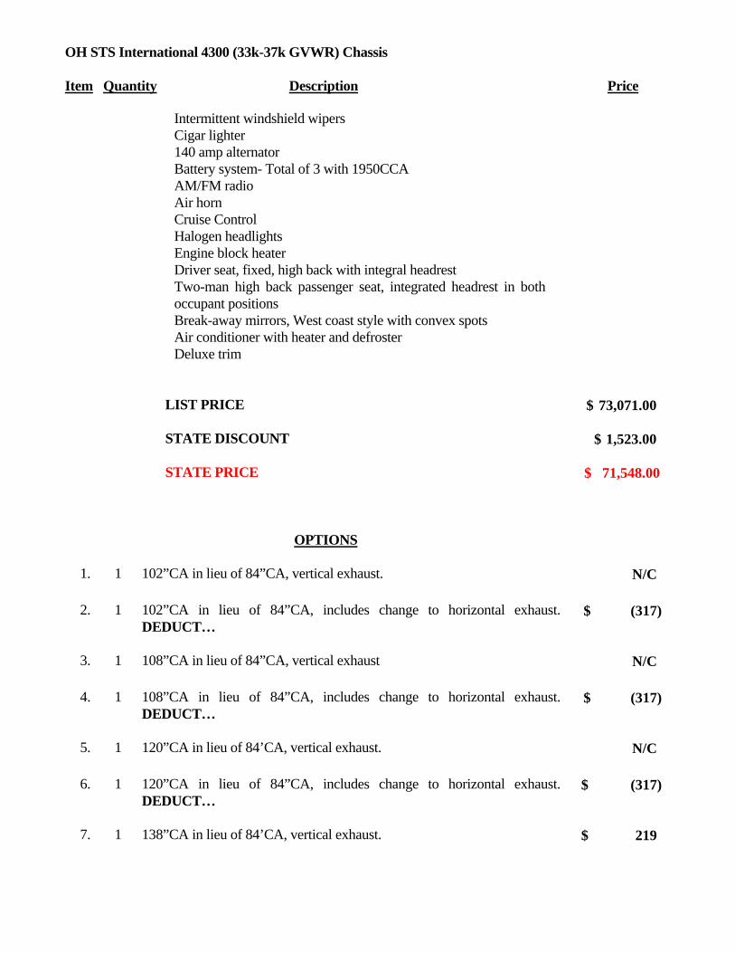
OH STS International 4300 (33k-37k GVWR) Chassis Item Quantity Description Price
Intermittent windshield wipers Cigar lighter 140 amp alternator Battery system- Total of 3 with 1950CCA AM/FM radio Air horn Cruise Control Halogen headlights Engine block heater Driver seat, fixed, high back with integral headrest Two-man high back passenger seat, integrated headrest in both occupant positions Break-away mirrors, West coast style with convex spots Air conditioner with heater and defroster Deluxe trim
LIST PRICE
73,071.00$
STATE DISCOUNT
1,523.00$
STATE PRICE
71,548.00$
OPTIONS
1. 1 102”CA in lieu of 84”CA, vertical exhaust.
N/C
2. 1 102”CA in lieu of 84”CA, includes change to horizontal exhaust. DEDUCT…
(317)$
3. 1 108”CA in lieu of 84”CA, vertical exhaust
N/C
4. 1 108”CA in lieu of 84”CA, includes change to horizontal exhaust. DEDUCT…
(317)$
5. 1 120”CA in lieu of 84’CA, vertical exhaust.
N/C
6. 1 120”CA in lieu of 84”CA, includes change to horizontal exhaust. DEDUCT…
(317)$
7. 1 138”CA in lieu of 84’CA, vertical exhaust.
219$

OH STS International 4300 (33k-37k GVWR) Chassis Item Quantity Description Price
8. 1 138”CA in lieu of 84”CA, includes change to horizontal exhaust. DEDUCT…
(155)$
9. 1 33,000lb GVWR (13,000lb FA and 20,000lb RA), includes horizontal exhaust on 102”CA and up. ADD…
831$
10. 1 33,000lb GVWR (14,000lb FA and 19,000lb RA), includes horizontal exhaust on 102”CA and up. ADD…
1,313$
11. 1 35,000lb GVWR (14,000lb FA and 21,000lb RA) includes horizontal exhaust on 102”CA and up. ADD…
1,560$
12. 1 35,000lb GVWR (12,000lb FA and 23,000lb RA) includes horizontal exhaust on 102”CA and up. ADD…
546$
13. 1 37,000lb GVWR (14,000lb FA and 23,000lb RA) includes horizontal exhaust on 102”CA and up. ADD…
1,983$
14. 1 Driver controlled locking differential (20,000lb rear axle and up). ADD…
1,219$
15. 1 Extended cab (26”) with rear bench seat (Minimum requirements are horizontal exhaust, single man passenger seat, 197”WB for 84”C usable CA) ADD…
3,161$
16. 1 Extended cab (26”) without rear bench seat (Minimum requirements are horizontal exhaust, single man passenger seat, 197”WB for 84”C usable CA) ADD…
2,786$
17. 1 Crew cab with rear bench seat (Minimum requirements are horizontal exhaust, single man passenger seat, 197”WB for 84”C usable CA) ADD…
7,576$
18. 1 Crew cab without rear bench seat (Minimum requirements are horizontal exhaust, single man passenger seat, 197”WB for 84”C usable CA) ADD…
7,201$
19. 1 6 Speed manual transmission. DEDUCT…
(5,331)$
20. 1 Heated mirrors. ADD…
124$
21. 1 Power windows. ADD…
114$
22. 1 Air Ride Driver seat, with arm rest. ADD…
199$

OH STS International 4300 (33k-37k GVWR) Chassis Item Quantity Description Price
23. 1 Single man air ride passenger seat, high back in lieu of 2 man bench. Air Ride Driver Seat required. ADD…
269$
24. 1 Delete A/C. DEDUCT…
(543)$
25. 1 Standard exterior color other than white
N/C
26. 1 Custom exterior color other than white. ADD…
375$
27. 1 Auxiliary power point in dash. ADD…
35$
28. 1 Exterior grab handle, chrome. On driver and passenger side of cab. ADD…
119$
29. 1 190 amp (or equivalent) alternator upgrade. ADD…
260$
30. 1 270 amp (or equivalent) alternator upgrade. ADD…
826$
31. 1 Tractor trailer towing package. ADD…
640$
32. 1 Front frame rail extension (delete front bumper). ADD…
241$
33. 1 Two way radio wiring effects. ADD…
78$

Altec Industries, Inc.
March 1, 2013
OH STS Contract #7751501908
International DuraStar 4400 (33k-37k GVWR) 4x2 Chassis
NOTE: Chassis’ are not for individual sale – all chassis orders must be in conjunction with unit/body order.
Item Quantity Description Price
CHASSIS 1. 1 2013 (or newer) 4400 4x2 cab and chassis
91”CA (84” usable, vertical exhaust) 12,000-lb. FAWR 21,000-lb. RAWR 33,000-lb. GVWR Transmission: Allison 3500RDS, 5 speed automatic transmission MaxxForce 7 Engine: 260 HP / 800 ft-lbs Vertical exhaust Fuel tank, 50 gallon, mounted under cab Exterior Color: 9219 winter white Front axle: 12,000 lb. I-beam type Rear axle: 21,000 lb, single reduction Front suspension: 12,000lb spring parabolic, taper leaf. Rear suspension: 23,500 lb. with 4500lb aux springs Conventional steel cab Fiberglass tilting front end Front tires- (2) G149 or equivalent Rear tires- (4) G177 or equivalent Dual air brake system Manual reset circuit breakers with trip indicators Remote engine throttle control Front and rear automatic slack adjusters Air dryer with heater Air compressor- 13.2 CFM Auto moisture ejectors Tilting steering column

OH STS International 4400 (33k-37k GVWR) Chassis Item Quantity Description Price
12-volt electrical system Intermittent windshield wipers Cigar lighter 140 amp alternator Battery system- Total of 3 with 1950CCA AM/FM radio Air horn Cruise Control Halogen headlights Engine block heater Driver seat, fixed, high back with integral headrest Two-man high back passenger seat, integrated headrest in both occupant positions Break-away mirrors, West coast style with convex spots Air conditioner with heater and defroster Deluxe trim
LIST PRICE
75,418.00$
STATE DISCOUNT
1,572.00$
STATE PRICE
73,846.00$
OPTIONS
1. 1 102”CA in lieu of 84”CA, vertical exhaust
N/C
2. 1 102”CA in lieu of 84”CA, includes change to horizontal exhaust. DEDUCT…
(325)$
3. 1 108”CA in lieu of 84”CA, vertical exhaust
N/C
4. 1 108”CA in lieu of 84”CA, includes change to horizontal exhaust. DEDUCT…
(325)$
5. 1 120”CA in lieu of 84”CA, vertical exhaust
N/C
6. 1 120”CA in lieu of 84”CA, includes change to horizontal exhaust. DEDUCT…
(325)$
7. 1 138”CA in lieu of 84”CA, vertical exhaust
219$

OH STS International 4400 (33k-37k GVWR) Chassis Item Quantity Description Price
8. 1 138”CA in lieu of 84”CA, includes change to horizontal exhaust. DEDUCT…
(160)$
9. 1 33,000lb GVWR (14,000lb FA and 19,000lb RA). ADD…
1,318$
10. 1 33,000lb GVWR (13,000lbFA and 20,000lb RA). ADD…
510$
11. 1 35,000lb GVWR (14,000lb FA and 21,000lb RA). ADD…
1,580$
12. 1 35,000lb GVWR (12,000lb FA and 23,000lb RA). ADD…
523$
13. 1 37,000lb GVWR (14,000lb FA and 23,000lb RA). ADD…
2,008$
14. 1 Driver controlled locking differential (20,000lb rear axle and up). ADD…
1,219$
15. 1 Extended cab (26”) with rear bench seat (Minimum requirements are horizontal exhaust, single man passenger seat, 197”WB for 84”C usable CA) ADD…
3,161$
16. 1 Extended cab (26”) without rear bench seat (Minimum requirements are horizontal exhaust, single man passenger seat, 197”WB for 84”C usable CA) ADD…
2,786$
17. 1 Crew cab with rear bench seat (Minimum requirements are horizontal exhaust, single man passenger seat, 197”WB for 84”C usable CA) ADD…
7,576$
18. 1 Crew cab without rear bench seat (Minimum requirements are horizontal exhaust, single man passenger seat, 197”WB for 84”C usable CA) ADD…
7,201$
19. 1 MaxxForce 285HP in lieu of 260HP. ADD…
595$
20. 1 Allison 3500RDS, 6 speed automatic transmission.
N/C
21. 1 6 speed manual transmission. DEDUCT…
(4,316)$
22. 1 Heated mirrors. ADD…
124$
23. 1 Power windows. ADD…
364$
24. 1 Air Ride Driver seat, with arm rest. ADD…
199$

OH STS International 4400 (33k-37k GVWR) Chassis Item Quantity Description Price
25. 1 Single man air ride passenger seat, high back in lieu of 2 man bench. Requires Air Ride Driver seat. ADD…
285$
26. 1 Delete A/C. DEDUCT…
(556)$
27. 1 Standard exterior color other than white.
N/C
28. 1 Custom exterior color other than white. ADD…
375$
29. 1 Auxiliary power point in dash. ADD…
35$
30. 1 Exterior grab handle, chrome. On driver and passenger side of cab. ADD…
119$
31. 1 180 amp (or equivalent) alternator upgrade. ADD…
265$
32. 1 270 amp (or equivalent) alternator upgrade. ADD…
846$
33. 1 Tractor trailer towing package. ADD…
640$
34. 1 Front frame rail extension (delete front bumper). ADD…
370$
35. 1 Two way radio wiring effects. ADD…
161$

Altec Industries, Inc.
March 1, 2013
OH STS Contract #7751501908
International WorkStar 7400 4x4 Chassis
NOTE: Chassis’ are not for individual sale – all chassis orders must be in conjunction with unit/body order.
Item Quantity Description Price
CHASSIS 1. 1 2013 (or newer) 7400 4x4 cab and chassis
120”CA 12,000-lb. FAWR 21,000-lb. RAWR 33,000-lb. GVWR Transmission: Allison 3500RDS, 5 speed automatic transmission MaxxForce Engine: 230HP / 620 ft-lbs Vertical exhaust (ONLY) Fuel tank, 50 gallon, mounted under cab Exterior Color: 9219 winter white Front axle: 12,000 lb. I-beam type Rear axle: 21,000 lb, single reduction Front suspension: 12,000 spring parabolic, taper leaf. Rear suspension: 23,500 lb. Conventional steel cab Fiberglass tilting front end Front tires- (2) G149 or equivalent Rear tires- (4) G177 or equivalent Dual air brake system Manual reset circuit breakers with trip indicators Remote engine throttle control Electric brake controller provision Front and rear automatic slack adjusters Air dryer with heater Air compressor- 13.2 CFM Auto moisture ejectors

OH STS International 7400 4x4 Chassis Item Quantity Description Price
Tilting steering column 12-volt electrical system Intermittent windshield wipers Cigar lighter 140 amp alternator Battery system- Total of 3 with 1950CCA AM/FM radio Air horn Cruise Control Halogen headlights Engine block heater Driver seat, fixed, high back with integral headrest Two-man high back passenger seat, integrated headrest in both occupant positions Break-away mirrors, West coast style with convex spots Air conditioner with heater and defroster Deluxe trim
LIST PRICE
87,185.00$
STATE DISCOUNT
1,817.00$
STATE PRICE
85,368.00$
OPTIONS
1. 1 138”CA in lieu of 120”CA. ADD…
431$
2. 1 35,000lb GVWR (14,000lb FA and 21,000lb RA). ADD…
2,665$
3. 1 35,000lb GVWR (12,000lb FA and 23,000lb RA). ADD…
645$
4. 1 37,000lb GVWR (14,000lb FA and 23,000lb RA). ADD…
3,106$
5. 1 39,000lb GVWR (16,000lb FA and 23,000lb RA). ADD…
5,249$
6. 1 Driver controlled locking differential (21k RA only). ADD…
823$
7. 1 Driver controlled locking differential (23k RA only). ADD…
1,036$

OH STS International 7400 4x4 Chassis Item Quantity Description Price
8. 1 Extended cab (26”) with rear bench seat (Minimum requirements are horizontal exhaust, single man passenger seat.) ADD…
2,666$
9. 1 Extended cab (26”) without rear bench seat (Minimum requirements are horizontal exhaust, single man passenger seat.) ADD…
2,541$
10. 1 Crew cab with rear bench seat (Minimum requirements are horizontal exhaust, single man passenger seat. Recommend horizontal exhaust.) ADD…
7,735$
11. 1 Crew cab without rear bench seat (Minimum requirements are horizontal exhaust, single man passenger seat. Recommend horizontal exhaust.) ADD…
7,485$
12. 1 MaxxForce 260HP in lieu of 225HP. ADD…
5,643$
13. 1 Maxx Force 300HP in lieu of 225HP ADD…
6,669$
14. 1 6 speed manual transmission. DEDUCT…
(5,723)$
15. 1 Heated mirrors. ADD…
126$
16. 1 Power windows. ADD…
626$
17. 1 Air Ride Driver seat, with arm rest. ADD…
203$
18. 1 Single man air ride passenger seat, high back in lieu of 2 man bench. Requires Air Ride Driver Seat. ADD…
293$
19. 1 Delete A/C. DEDUCT…
(570)$
20. 1 Standard exterior color other than white.
N/C
21. 1 Custom exterior color other than white. ADD…
375$
22. 1 Auxiliary power point in dash. ADD…
35$
23. 1 Exterior grab handle, driver side only. ADD…
119$
24. 1 180 amp (or equivalent) alternator upgrade. ADD…
273$

OH STS International 7400 4x4 Chassis Item Quantity Description Price
25. 1 270 amp (or equivalent) alternator upgrade. ADD…
868$
26. 1 Tractor trailer towing package with rear glad hands. ADD…
603$
27. 1 Front frame rail extension (delete front bumper). ADD…
330$
28. 1 Two way radio wiring effects. ADD…
159$

Altec Industries, Inc.
March 1, 2013
OH STS Contract #7751501908
International WorkStar 7400 6x4 Chassis
NOTE: Chassis’ are not for individual sale – all chassis orders must be in conjunction with unit/body order.
Item Quantity Description Price
CHASSIS 1. 1 2013 (or newer) 7400 6x4 cab and chassis-
120”CT 12,000-lb. FAWR 40,000-lb. RAWR 52,000-lb. GVWR Transmission: Allison 3500RDS, 5 speed automatic transmission MaxxForce DT Engine: 230 HP / 620 ft-lbs Vertical exhaust Fuel tank, 50 gallon, mounted under cab Exterior Color: 9219 winter white Front axle: 12,000 lb. I-beam type Rear axle: 40,000 lb Dana Spicer single reduction, Front suspension: 12,000 spring parabolic, taper leaf. Rear suspension: 40,000 lb. Conventional steel cab Fiberglass tilting front end Front tires- (2) G149 or equivalent Rear tires- (4) G177 or equivalent Dual air brake system Manual reset circuit breakers with trip indicators Remote engine throttle control Electric brake controller provision Front and rear automatic slack adjusters Air dryer with heater Air compressor- 13.2 CFM Auto moisture ejectors

OH STS International 7400 6x4 Chassis Item Quantity Description Price
Tilting steering column 12-volt electrical system Intermittent windshield wipers Cigar lighter 140 amp alternator Battery system- Total of 3 with 1950CCA AM/FM radio Air horn Cruise Control Halogen headlights Engine block heater Driver seat, fixed, high back with integral headrest Two-man high back passenger seat, integrated headrest in both occupant positions Break-away mirrors, West coast style with convex spots Air conditioner with heater and defroster Deluxe trim
LIST PRICE
84,523.00$
STATE DISCOUNT
1,761.00$
STATE PRICE
82,762.00$
OPTIONS
1. 1 138”CA in lieu of 120”CA
N/C
2. 1 48,000lb GVWR (14,000lb FA and 34,000lb RA. Note: No rear locking diff available). ADD…
1,176$
3. 1 54,000lb GVWR (14,000lb FA and 40,000lb RA) ADD…
1,269$
4. 1 56,000lb GVWR (16,000lb FA and 40,000lb RA). ADD…
3,969$
5. 1 Driver controlled locking differential (40k rear axle only) ADD…
1,029$
6. 1 Extended cab (26”) with rear bench seat (Minimum requirements are horizontal exhaust, single man passenger seat.) ADD…
2,666$
7. 1 Extended cab (26”) without rear bench seat 2,541$

OH STS International 7400 6x4 Chassis Item Quantity Description Price
(Minimum requirements are horizontal exhaust, single man passenger seat.) ADD…
8. 1 Crew cab with rear bench seat (Minimum requirements are horizontal exhaust, single man passenger seat. Recommend horizontal exhaust.) ADD…
7,735$
9. 1 Crew cab without rear bench seat (Minimum requirements are horizontal exhaust, single man passenger seat. Recommend horizontal exhaust.) ADD…
7,485$
10. 1 MaxxForce 260HP in lieu of 230HP. ADD…
1,279$
11. 1 MaxxForce 300HP in lieu of 230HP. ADD…
2,261$
12. 1 10 speed manual transmission. DEDUCT…
(5,122)$
13. 1 Horizontal exhaust in lieu of vertical. DEDUCT…
101$
14. 1 Heated mirrors. ADD…
126$
15. 1 Power windows. ADD…
319$
16. 1 Air Ride Driver seat, with arm rest. ADD…
319$
17. 1 Single man air ride passenger seat, high back in lieu of 2 man bench. (Requires Air Ride Driver Seat). ADD…
293$
18. 1 Delete A/C. DEDUCT…
(570)$
19. 1 Standard exterior color other than white. ADD…
N/C
20. 1 Custom exterior color other than white. ADD…
375$
21. 1 Auxiliary power point in dash. ADD…
35$
22. 1 Exterior grab handle, driver side only. ADD…
118$
23. 1 180 amp (or equivalent) alternator upgrade. ADD…
273$
24. 1 270 amp (or equivalent) alternator upgrade. ADD…
868$
25. 1 Tractor trailer towing package. ADD… 603$

OH STS International 7400 6x4 Chassis Item Quantity Description Price
26. 1 Front frame rail extension (delete front bumper). ADD…
330$
27. 1 Two way radio wiring effects. ADD…
159$


