Alteration of Telstra facilities in homes & small businesses Information for cabling providers TELSTRA CORPORATION LIMITED (ABN 33 051 775 556) | ISSUED 26/08/2013 ISSUE 4 – FINAL | TELSTRA UNRESTRICTED | DOCUMENT NO. 012882 | ALTERATION OF TELSTRA FACILITIES IN HOMES & SMALL BUSINESSES PAGE 1/193 Author’s name Business unit Telstra Operations Sub-business unit Access Technology Planning Issue date 26 August 2013 Issue number 4 Telstra ID 012882 Summary This Document authorises registered cabling providers to alter internal (indoor) Telstra copper twisted pair lead-in cabling in a home or a small business up to and including the first socket and sets out the terms and conditions under which such alterations are authorised by Telstra. Please think twice about printing this Document for reading or future reference. If you need it away from the office, save it to your tablet or portable computer and enjoy the advantages of being able to use the hyperlinks, document search functions and on-screen magnification of photographs and drawings. This publication has been prepared and written by Telstra Corporation Limited (ABN 33 051 775 556), and is copyright. Other than for the purposes of and subject to the conditions prescribed under the Copyright Act, no part of it may in any form or by any means (electronic, mechanical, microcopying, photocopying, recording or otherwise) be reproduced, stored in a retrieval system or transmitted without prior written permission from the document controller. Product or company names are trademarks or registered trademarks of their respective holders. Note for non-Telstra readers: The contents of this publication are subject to change without notice. All efforts have been made to ensure the accuracy of this publication. Notwithstanding, Telstra Corporation Limited does not assume responsibility for any errors nor for any consequences arising from any errors in this publication.
Transcript
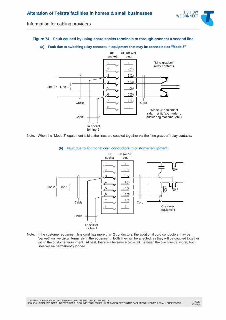
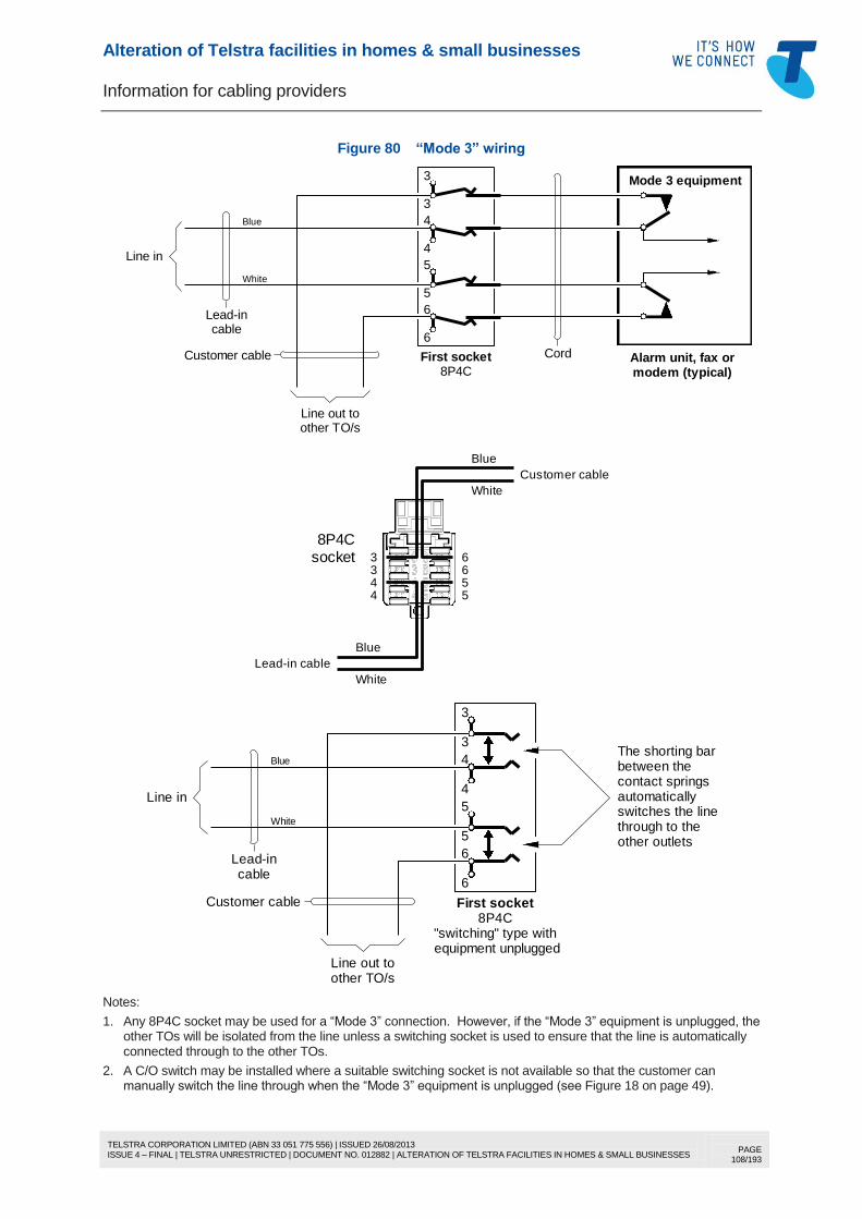
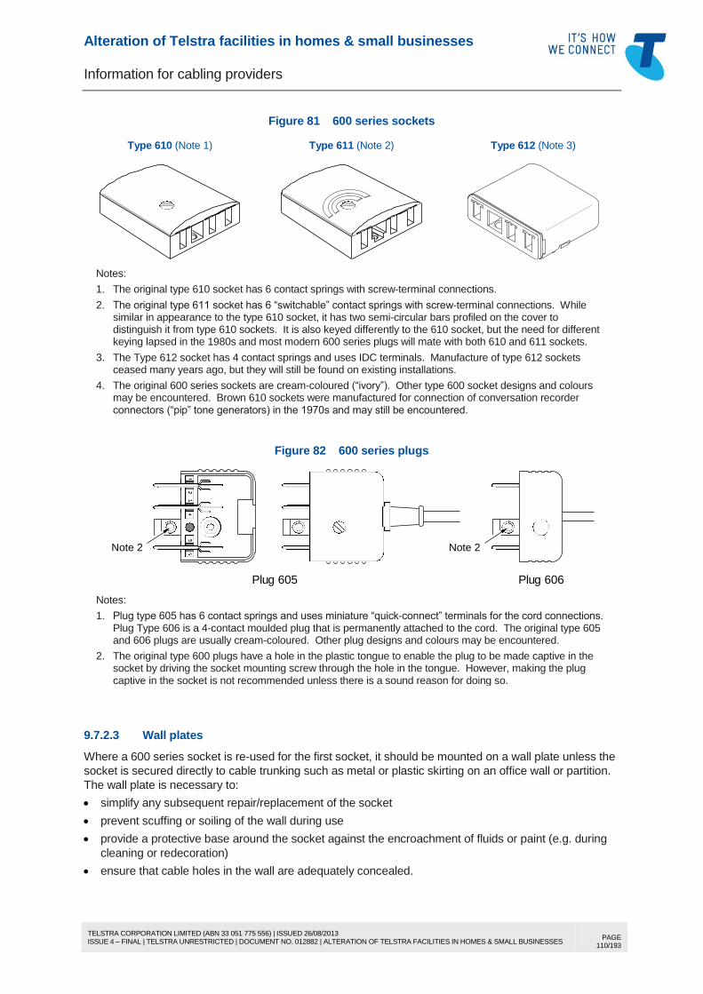
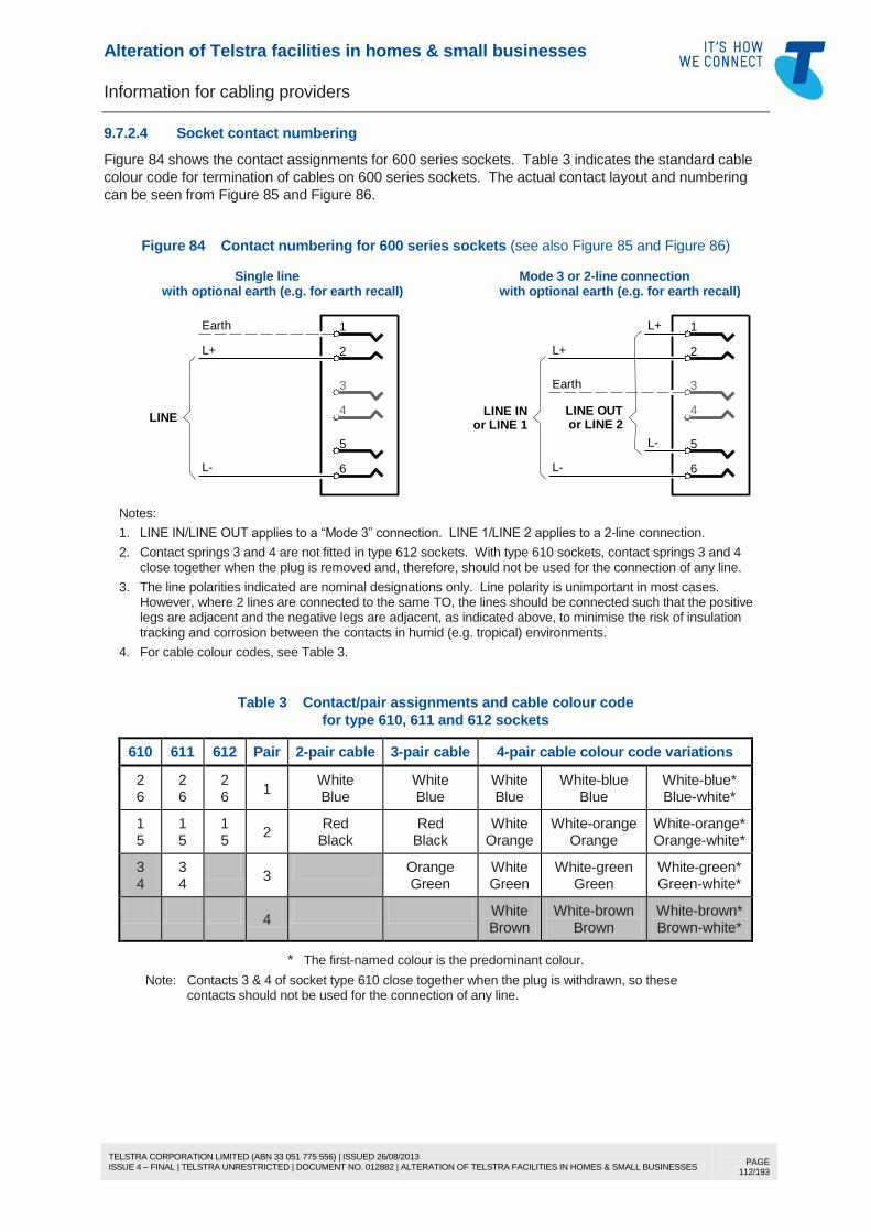
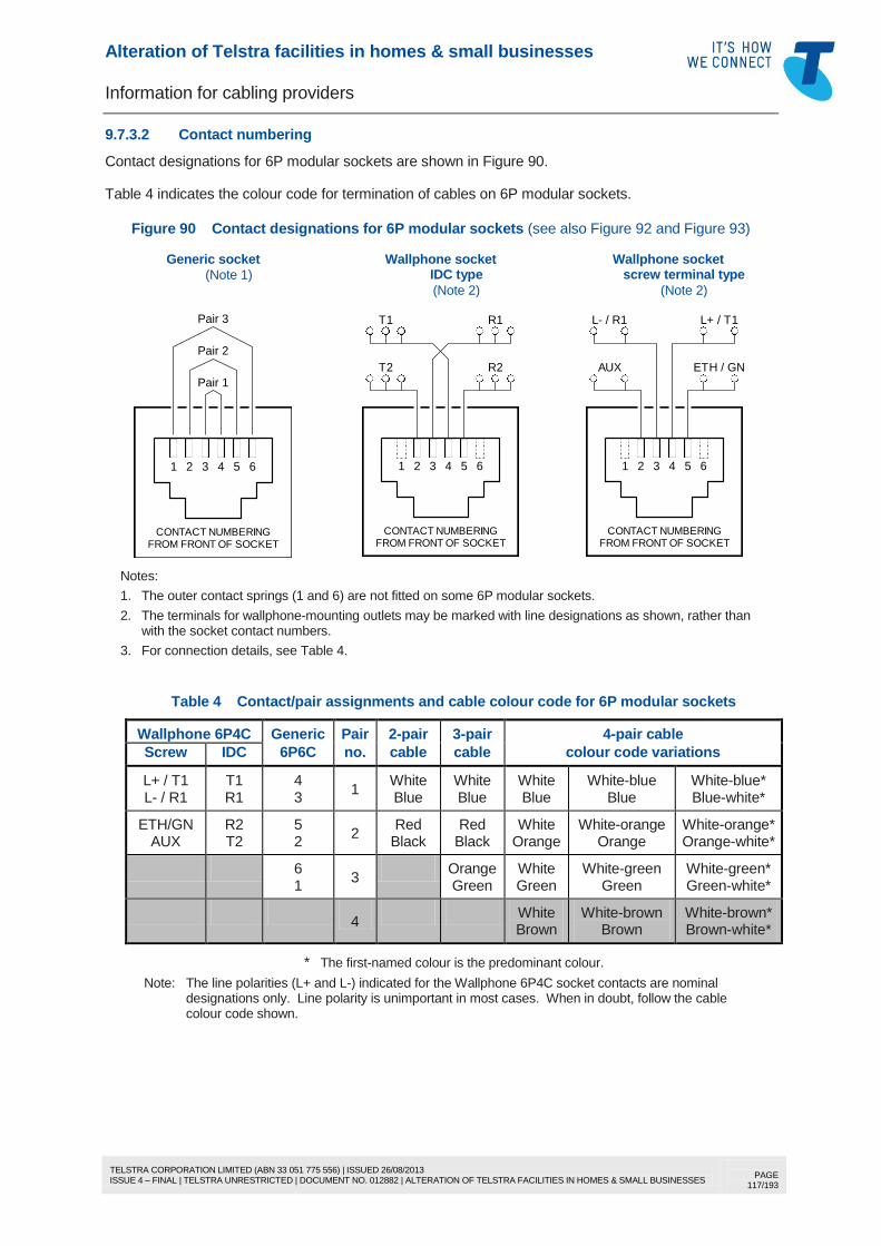
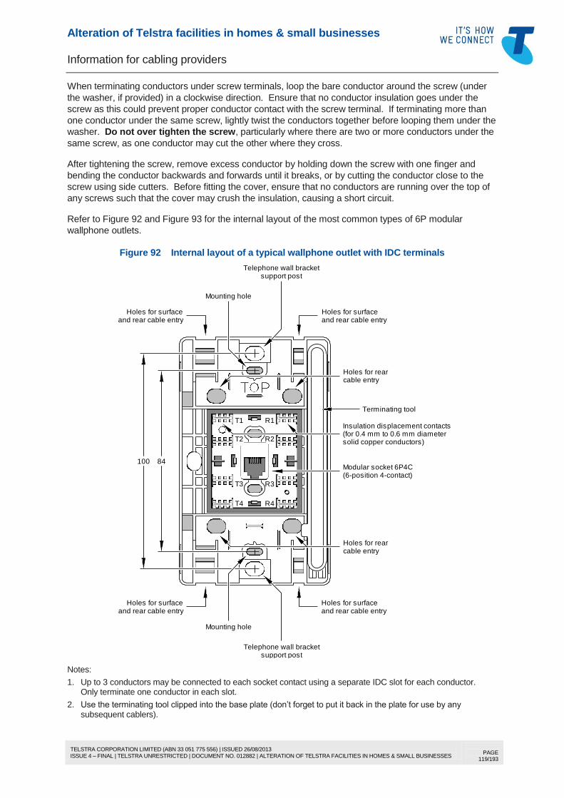
Alteration of Telstra facilities in homes & small businesses
Information for cabling providers
TELSTRA CORPORATION LIMITED (ABN 33 051 775 556) | ISSUED 26/08/2013 ISSUE 4 – FINAL | TELSTRA UNRESTRICTED | DOCUMENT NO. 012882 | ALTERATION OF TELSTRA FACILITIES IN HOMES & SMALL BUSINESSES
PAGE 1/193
Author’s name
Business unit
Telstra Operations
Sub-business unit
Access Technology Planning
Issue date
26 August 2013
Issue number
4
Telstra ID
012882
Summary
This Document authorises registered cabling providers to alter internal (indoor) Telstra copper twisted
pair lead-in cabling in a home or a small business up to and including the first socket and sets out the
terms and conditions under which such alterations are authorised by Telstra.
Please think twice about printing this Document for reading or future reference. If you need it away from
the office, save it to your tablet or portable computer and enjoy the advantages of being able to use the
hyperlinks, document search functions and on-screen magnification of photographs and drawings.
This publication has been prepared and written by Telstra Corporation Limited (ABN 33 051 775 556), and is copyright. Other than for the purposes of and subject to the conditions prescribed under the Copyright Act, no part of it may in any form or by any means (electronic, mechanical, microcopying, photocopying, recording or otherwise) be reproduced, stored in a retrieval system or transmitted without prior written permission from the document controller. Product or company names are trademarks or registered trademarks of their respective holders.
Note for non-Telstra readers: The contents of this publication are subject to change without notice. All efforts have been made to ensure the accuracy of this publication. Notwithstanding, Telstra Corporation Limited does not assume responsibility for any errors nor for any consequences arising from any errors in this publication.
Alteration of Telstra facilities in homes & small businesses
Information for cabling providers
TELSTRA CORPORATION LIMITED (ABN 33 051 775 556) | ISSUED 26/08/2013 ISSUE 4 – FINAL | TELSTRA UNRESTRICTED | DOCUMENT NO. 012882 | ALTERATION OF TELSTRA FACILITIES IN HOMES & SMALL BUSINESSES
PAGE 2/193
(INTENTIONALLY BLANK)
Alteration of Telstra facilities in homes & small businesses
Information for cabling providers
TELSTRA CORPORATION LIMITED (ABN 33 051 775 556) | ISSUED 26/08/2013 ISSUE 4 – FINAL | TELSTRA UNRESTRICTED | DOCUMENT NO. 012882 | ALTERATION OF TELSTRA FACILITIES IN HOMES & SMALL BUSINESSES
4.2.1 General.................................................................................................................. 13 4.2.2 Cabling alterations limited to cabling in or on the building .................................. 13 4.2.3 Materials and practices must be to Telstra’s standards ...................................... 13 4.2.4 Alterations not authorised where network equipment is installed at the
first point ................................................................................................................ 14 4.3 Legal issues .......................................................................................................................... 14
4.3.1 The network boundary .......................................................................................... 14 4.3.2 Carrier ownership or operation of facilities and unlawful tampering or
interference with those facilities ........................................................................... 14 4.3.3 Telecommunications Act 1997 ............................................................................. 14 4.3.4 Criminal Code 1995 (Cth) ..................................................................................... 15 4.3.5 Common law ......................................................................................................... 15 4.3.6 What does Telstra own or operate? ..................................................................... 15 4.3.7 Performance of cabling work ................................................................................ 15 4.3.8 Telstra may revoke or vary authorisation ............................................................. 15 4.3.9 Telstra “accreditation” ........................................................................................... 16
4.4 Interpretation ......................................................................................................................... 16 5 AUTHORISED WORK .................................................................................................................... 17
5.1 About this section .................................................................................................................. 17 5.2 General terms and conditions .............................................................................................. 17 5.3 Replacement of the first TO .................................................................................................. 18 5.4 Relocation of the first TO ...................................................................................................... 18 5.5 Fixed Telstra wallphone or other hard-wired telephone ...................................................... 19
5.5.1 Replacement or relocation ................................................................................... 19 5.5.2 Disconnection ....................................................................................................... 19
5.6 Star-wired TOs ...................................................................................................................... 19 5.6.1 TO alterations ....................................................................................................... 19 5.6.2 Additional TOs ...................................................................................................... 19 5.6.3 Reconfiguration of the wiring ................................................................................ 20
5.10 Disconnection of Telstra lead-in cabling .............................................................................. 21 5.11 Use of Telstra lead-in poles for customer cabling ............................................................... 22
6 DESCRIPTION OF BASIC TELSTRA INSTALLATIONS .............................................................. 25 6.1 General .................................................................................................................................. 25 6.2 Lightning surge suppression ................................................................................................ 26
Alteration of Telstra facilities in homes & small businesses
Information for cabling providers
TELSTRA CORPORATION LIMITED (ABN 33 051 775 556) | ISSUED 26/08/2013 ISSUE 4 – FINAL | TELSTRA UNRESTRICTED | DOCUMENT NO. 012882 | ALTERATION OF TELSTRA FACILITIES IN HOMES & SMALL BUSINESSES
7.3.1 General.................................................................................................................. 30 7.3.2 Use of private poles and trees .............................................................................. 30 7.3.3 Use of power utility poles ...................................................................................... 30 7.3.4 Inspection and maintenance of poles .................................................................. 30 7.3.5 Use of Telstra poles for power mains .................................................................. 30 7.3.6 Use of Telstra poles for customer cabling ........................................................... 31
7.4 What a cabling provider is authorised to do ......................................................................... 31 7.4.1 Disconnection of underground or aerial lead-in cabling ...................................... 31 7.4.2 Use of Telstra lead-in poles for customer cabling ............................................... 32
7.5 What a cabling provider is not authorised to do .................................................................. 33 8 CABLING IN OR ON THE BUILDING ............................................................................................ 34
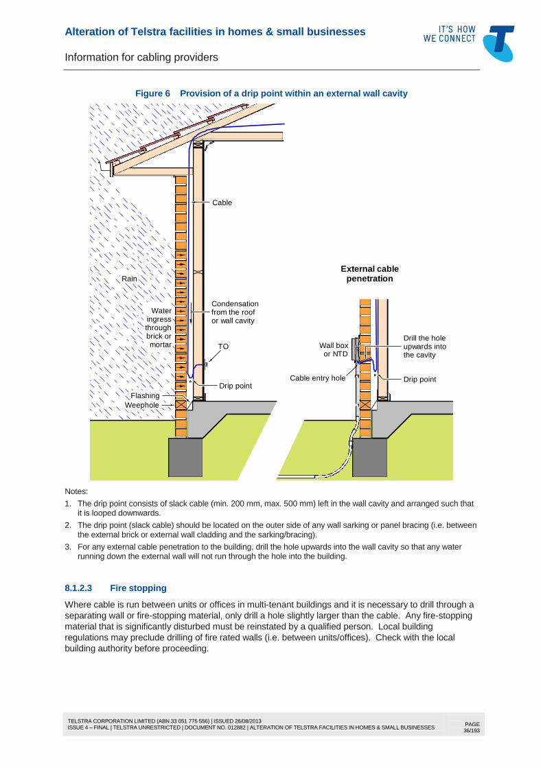
8.1 Cabling the first TO ............................................................................................................... 34 8.1.1 Cable type ............................................................................................................. 34 8.1.2 Cable installation ................................................................................................... 34
8.2 Cable joints............................................................................................................................ 37 8.3 Method of cabling TOs.......................................................................................................... 38
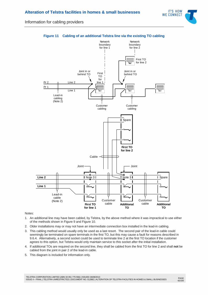
8.3.1 TOs connected to the same line .......................................................................... 38 8.3.2 Cabling of an additional Telstra access line ........................................................ 38
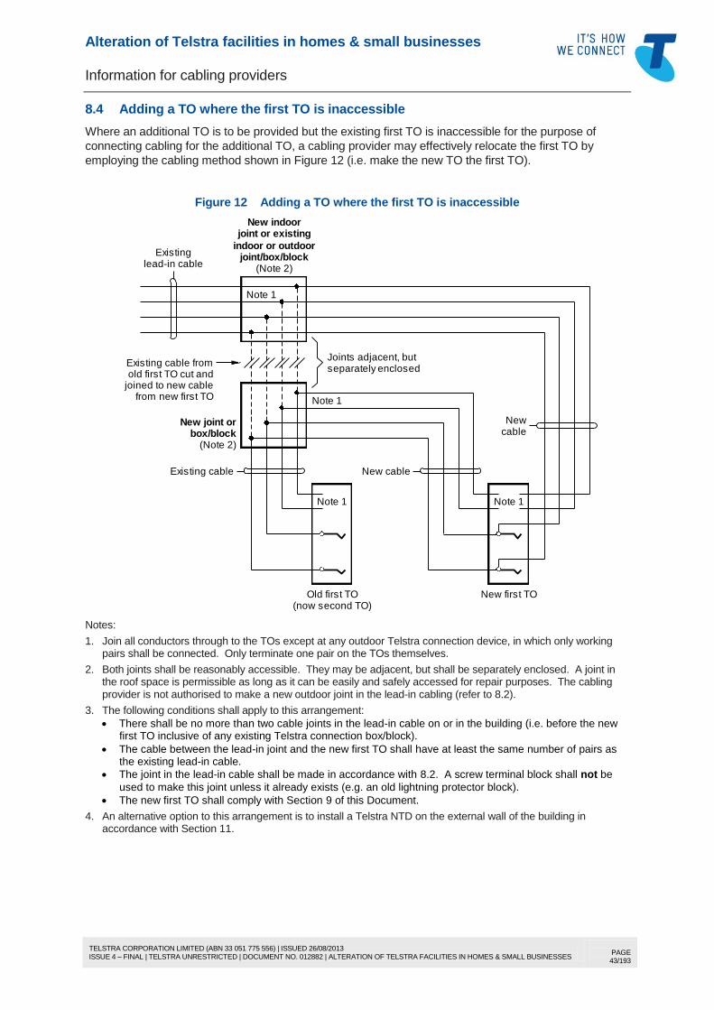
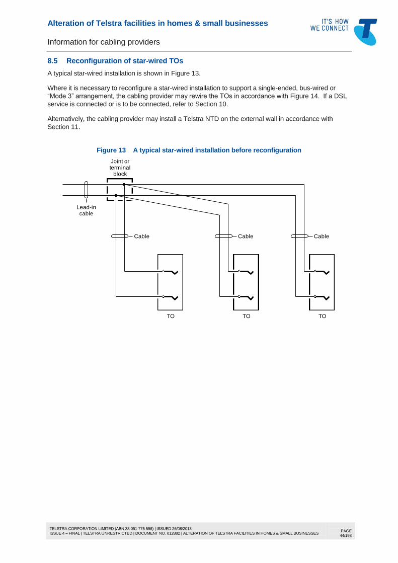
8.4 Adding a TO where the first TO is inaccessible ................................................................... 43 8.5 Reconfiguration of star-wired TOs ....................................................................................... 44 8.6 TOs wired from a redundant first TO.................................................................................... 46 8.7 C/O (changeover) switch ...................................................................................................... 46
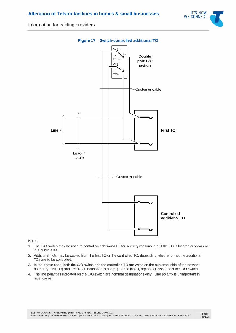
8.7.1 Description ............................................................................................................ 46 8.7.2 Existing C/O switch connected to the lead-in cable ............................................ 46 8.7.3 C/O switch connected on the customer side of the first socket .......................... 47 8.7.4 Installation of a new C/O switch ........................................................................... 50
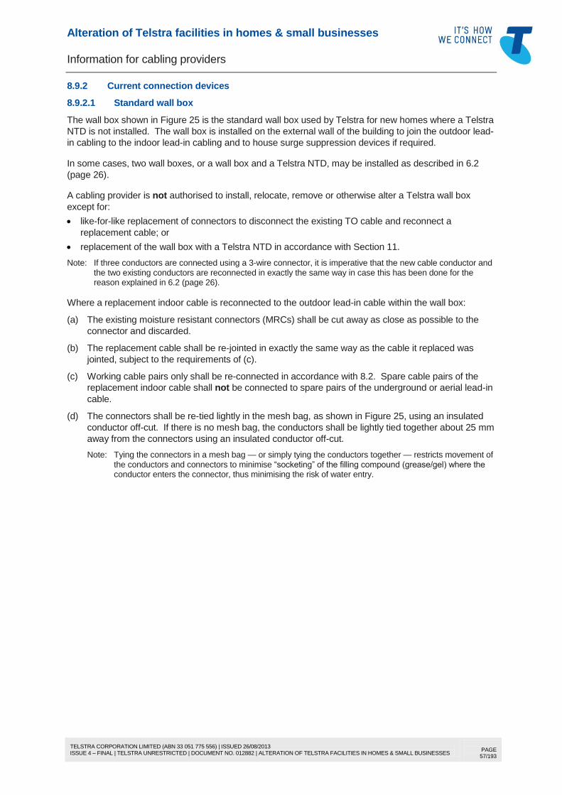
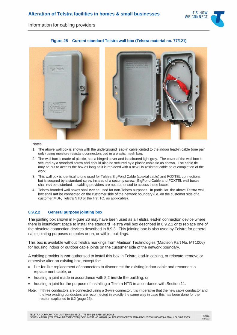
8.9 Telstra wall boxes and other connection devices ................................................................ 56 8.9.1 General.................................................................................................................. 56 8.9.2 Current connection devices .................................................................................. 57 8.9.3 Obsolete connection devices ............................................................................... 60
9 THE FIRST TELECOMMUNICATIONS OUTLET ......................................................................... 77 9.1 The difference between a “TO” (or an “outlet”) and a “socket” ........................................... 77 9.2 Materials ................................................................................................................................ 77
9.2.1 Description ............................................................................................................ 77 9.2.2 Painting of TOs ..................................................................................................... 77
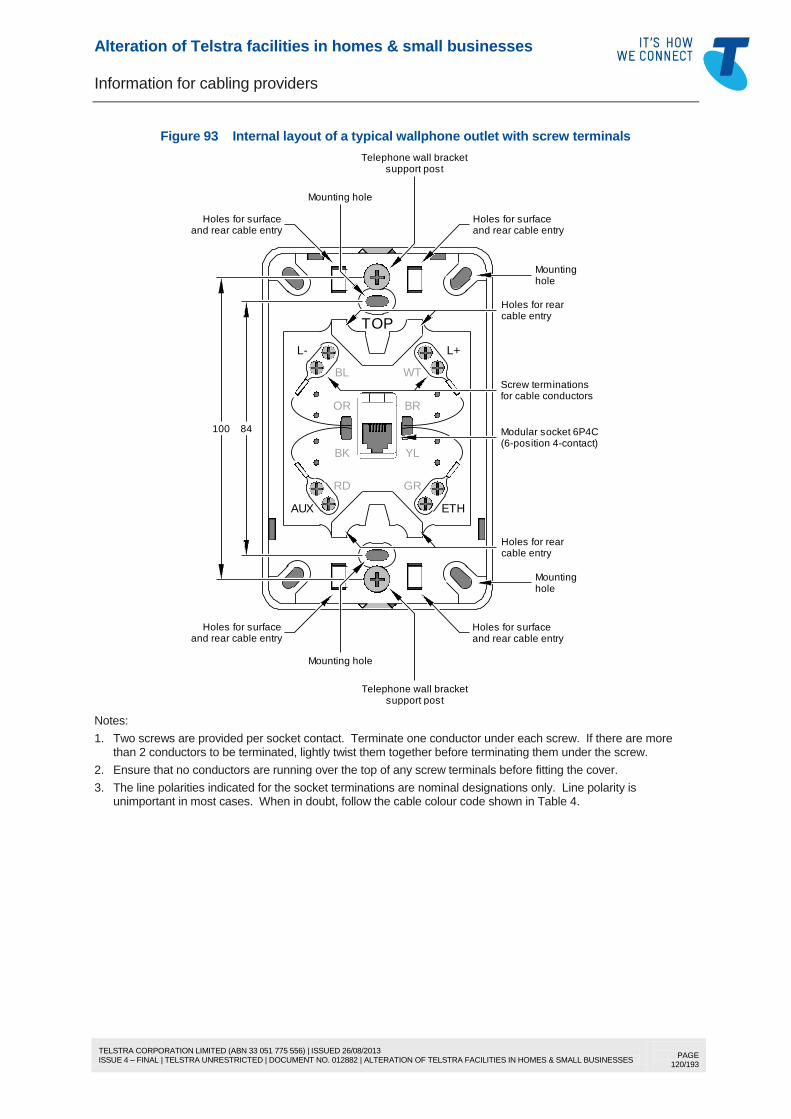
9.3 General description of approved Telstra TOs ...................................................................... 77 9.4 Selection of the appropriate socket and mounting .............................................................. 80
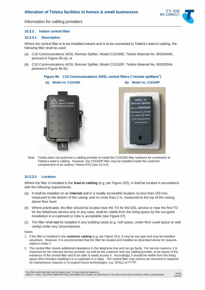
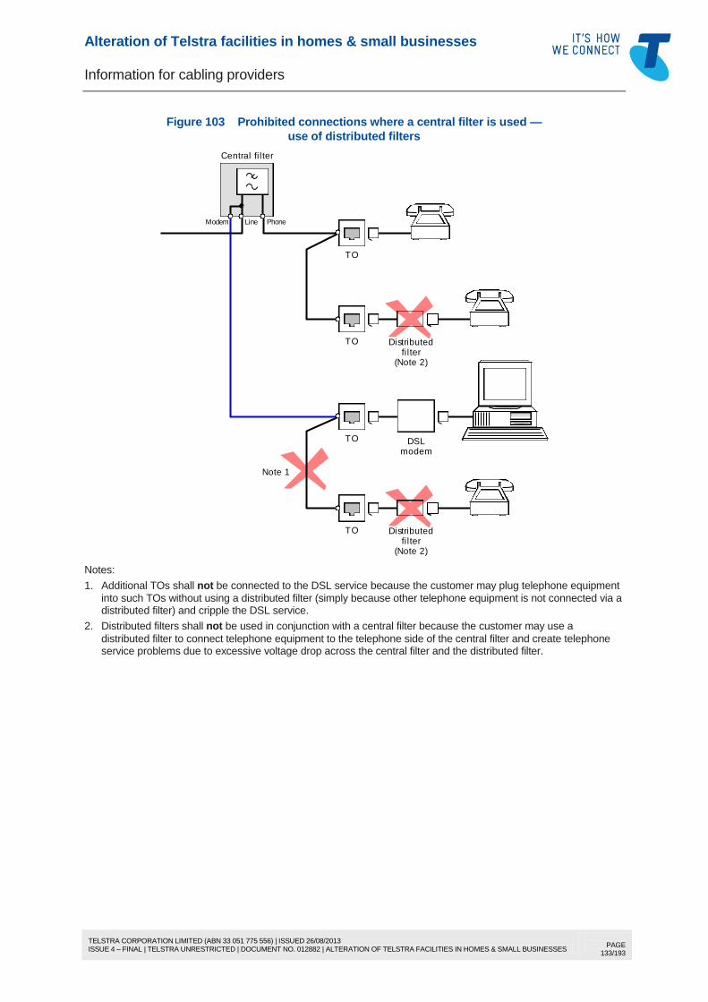
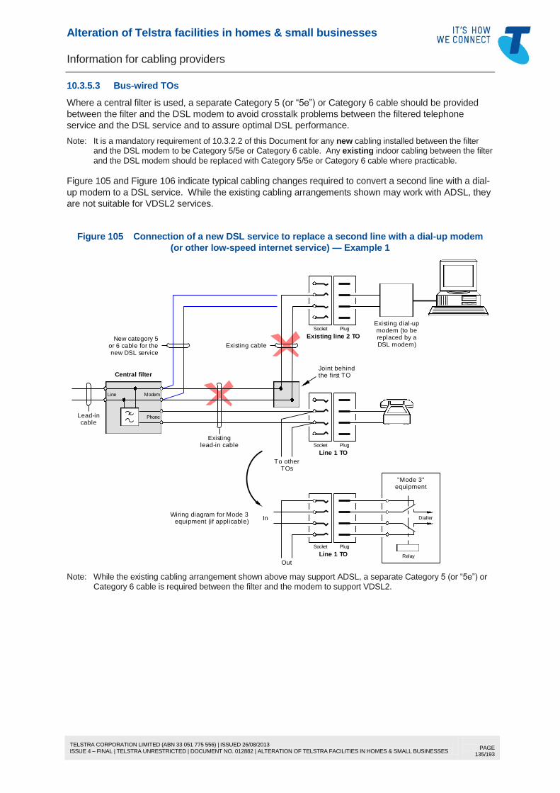
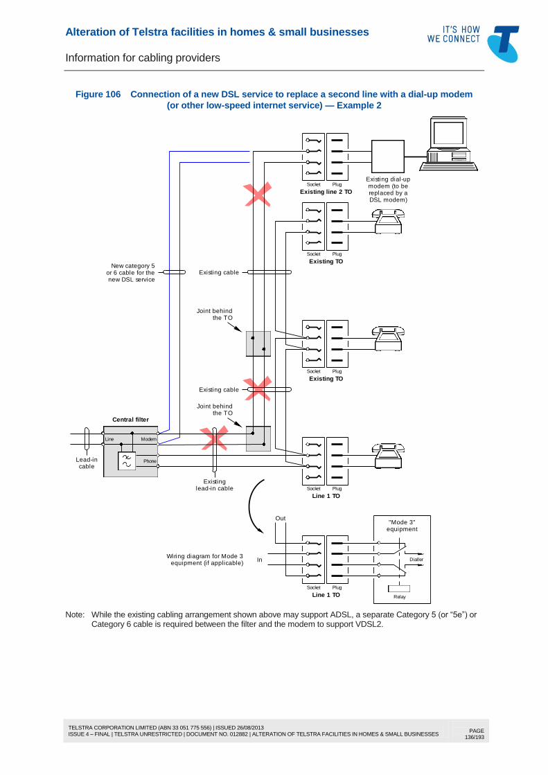
10.3.1 When is a central filter required?........................................................................ 124 10.3.2 Central filter installation ...................................................................................... 124 10.3.3 Indoor central filter .............................................................................................. 126 10.3.4 Outdoor central filter ........................................................................................... 129 10.3.5 Central filter wiring .............................................................................................. 130
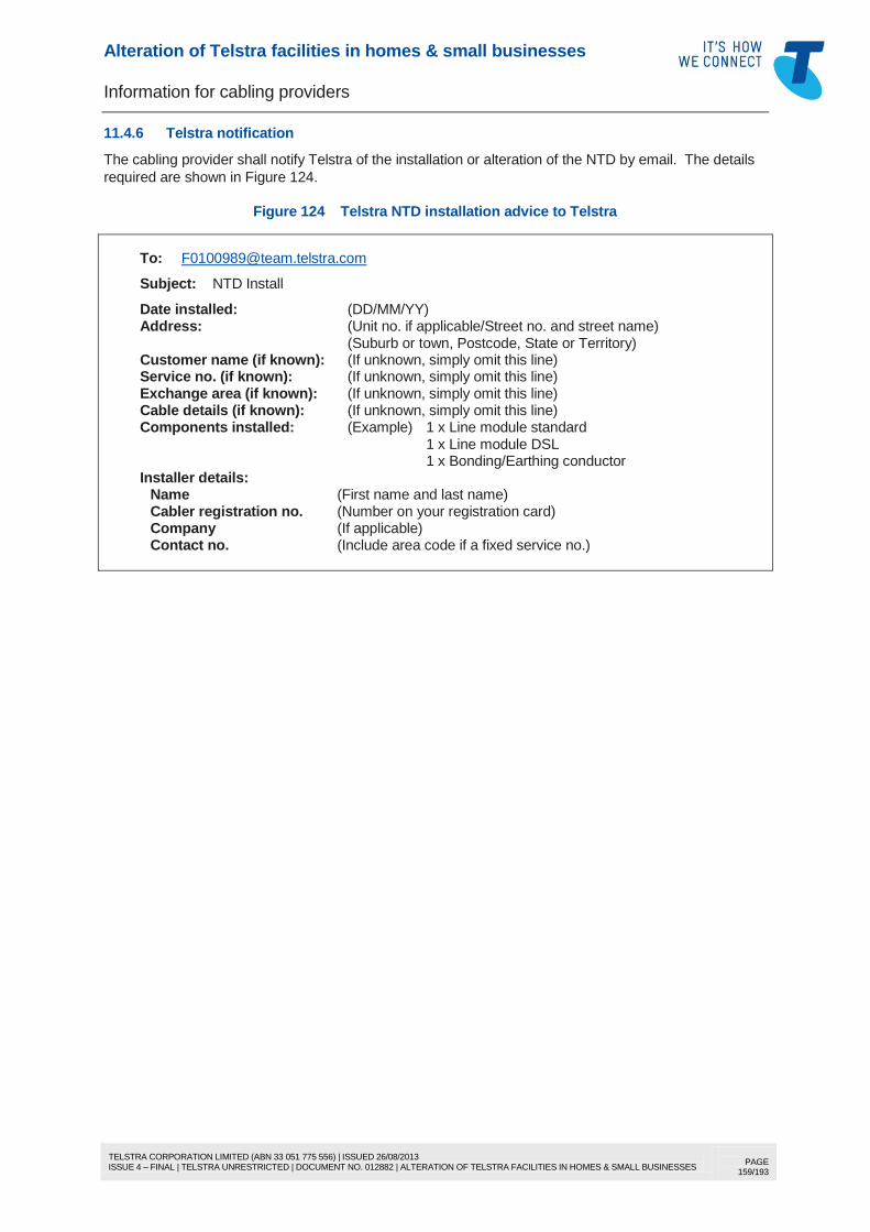
11 TELSTRA NETWORK TERMINATION DEVICE (NTD) .............................................................. 153 11.1 Description .......................................................................................................................... 153 11.2 The benefits of using an NTD ............................................................................................. 155
11.2.1 General................................................................................................................ 155 11.2.2 Telstra NTD ......................................................................................................... 155 11.2.3 Where the use of an NTD is recommended ...................................................... 155
11.3 What a cabling provider is authorised to do ....................................................................... 155 11.3.1 Alteration ............................................................................................................. 155 11.3.2 Installation ........................................................................................................... 156
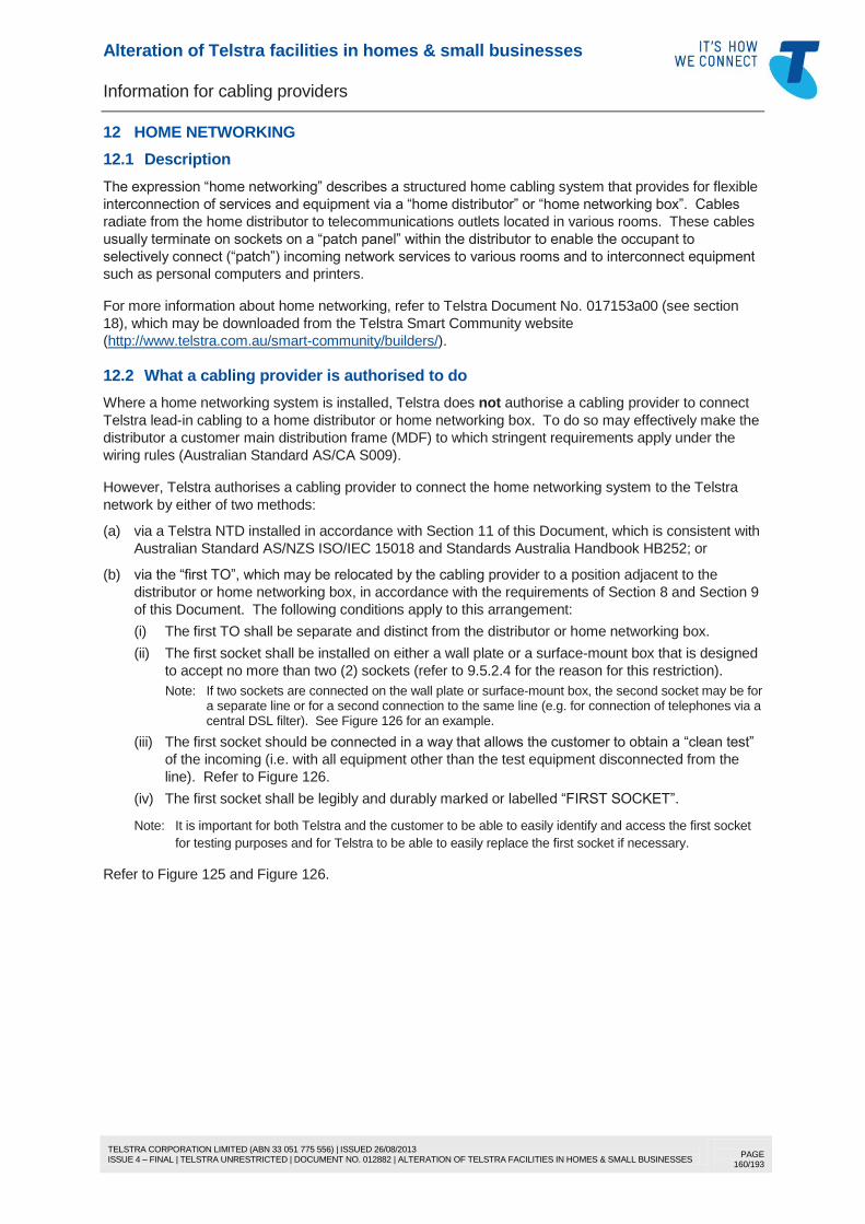
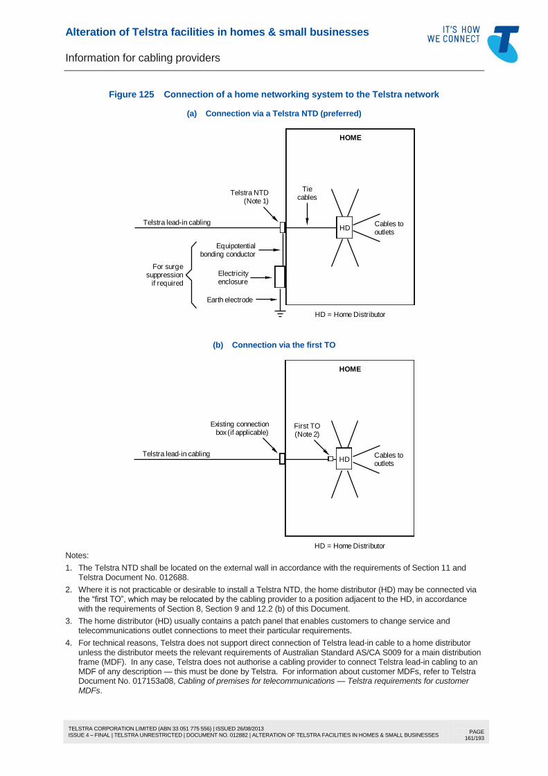
12 HOME NETWORKING .................................................................................................................. 160 12.1 Description .......................................................................................................................... 160 12.2 What a cabling provider is authorised to do ....................................................................... 160
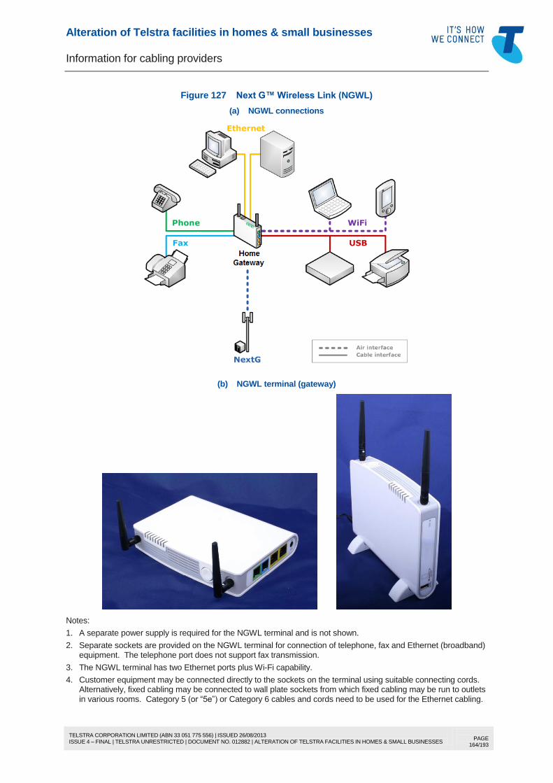
13 NEXTG™ WIRELESS LINK ......................................................................................................... 163 13.1 Description .......................................................................................................................... 163 13.2 Fixed wireless terminal inside the building ......................................................................... 163 13.3 Underground or aerial cabling from an external radio shelter ........................................... 165
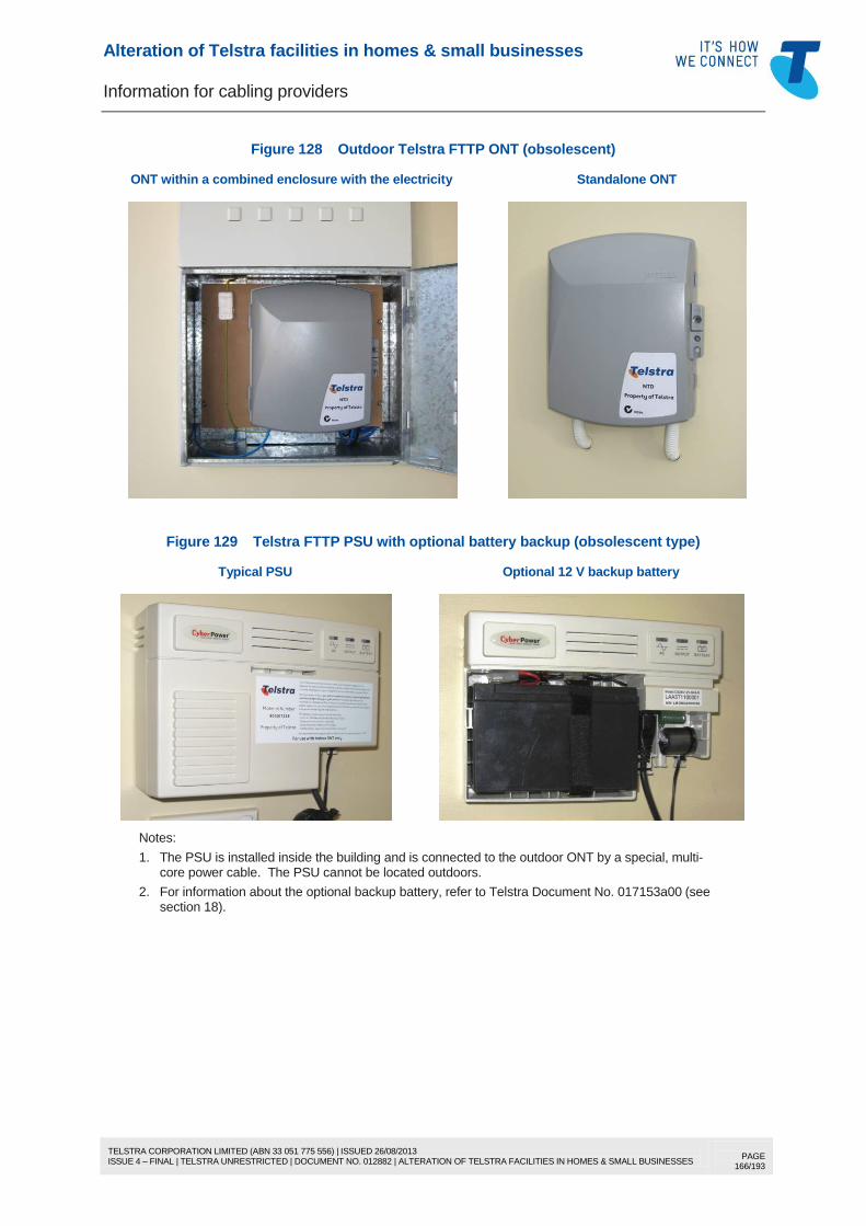
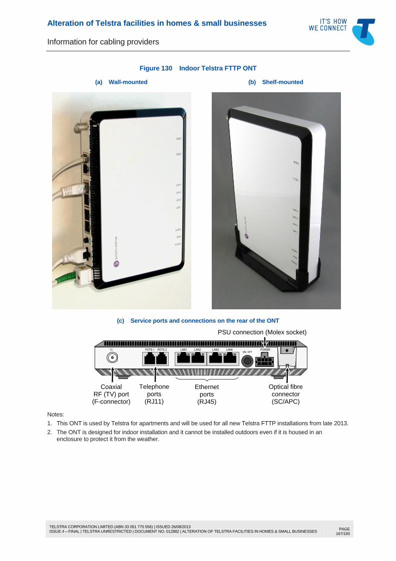
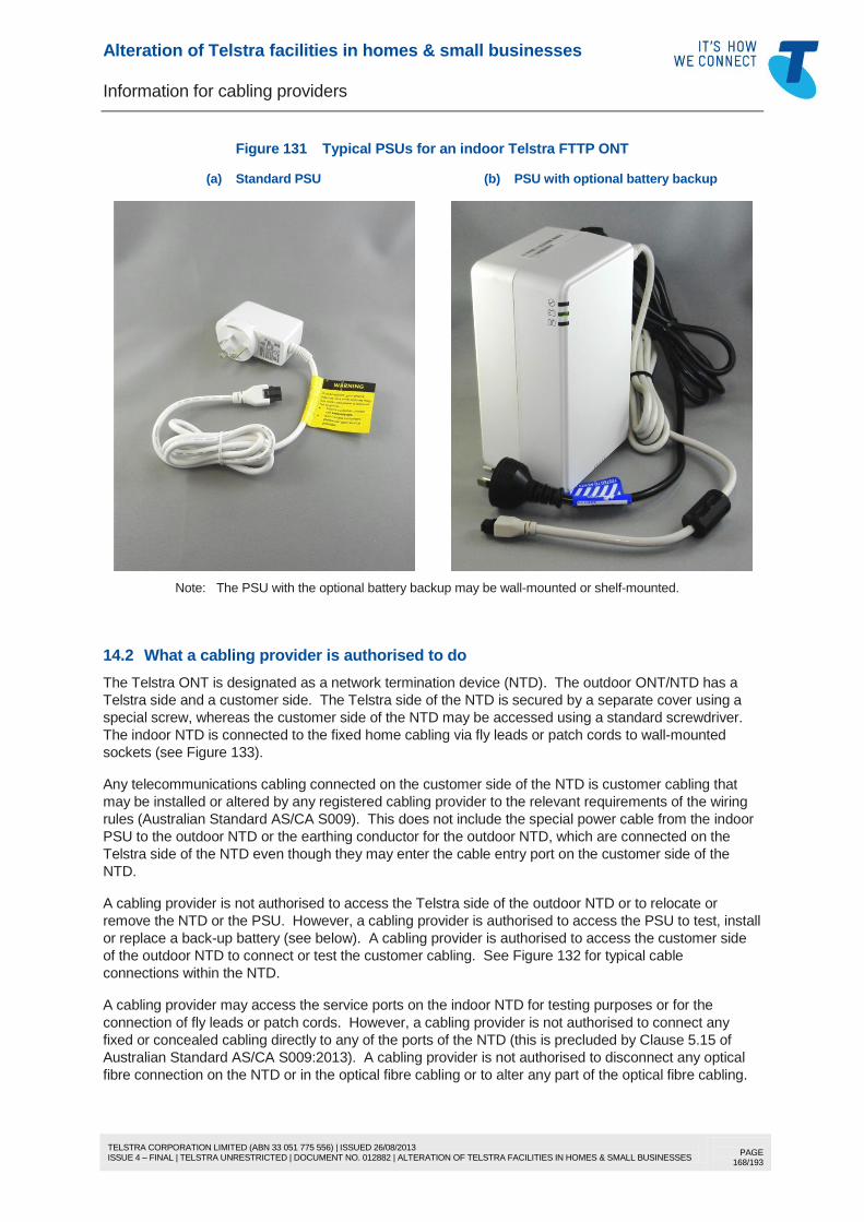
14 FIBRE TO THE PREMISES (FTTP) ............................................................................................. 165 14.1 Description .......................................................................................................................... 165 14.2 What a cabling provider is authorised to do ....................................................................... 168
15 CUSTOMER NOTIFICATION OF A CHANGE TO THE NETWORK BOUNDARY ................... 172
Alteration of Telstra facilities in homes & small businesses
Information for cabling providers
TELSTRA CORPORATION LIMITED (ABN 33 051 775 556) | ISSUED 26/08/2013 ISSUE 4 – FINAL | TELSTRA UNRESTRICTED | DOCUMENT NO. 012882 | ALTERATION OF TELSTRA FACILITIES IN HOMES & SMALL BUSINESSES
PAGE 6/193
16 CONTACTING TELSTRA ............................................................................................................. 174 16.1 General ................................................................................................................................ 174 16.2 Contact numbers for cabling enquiries .............................................................................. 174
16.2.1 Lead-in cable pre-provisioning (pre-wiring or “roughing in”) of a new building ................................................................................................................ 174
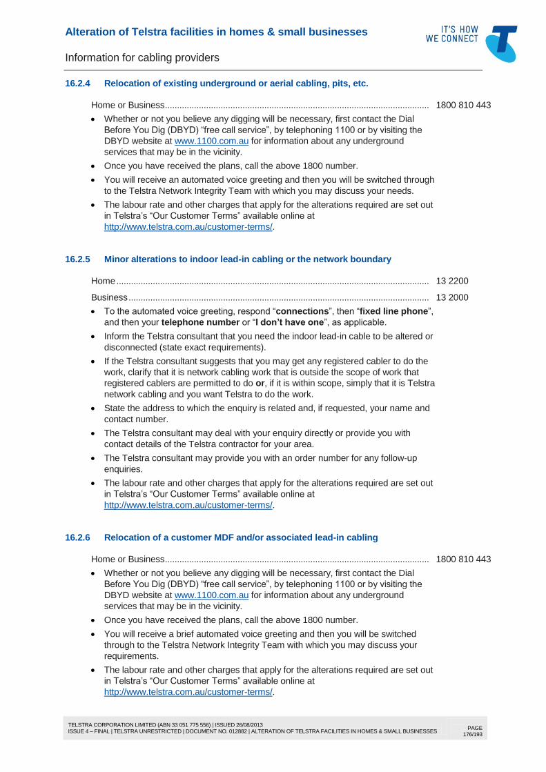
16.2.2 Connection of a new service (whether or not the building is pre-wired) ........... 175 16.2.3 To request advice about lead-in trenching requirements .................................. 175 16.2.4 Relocation of existing underground or aerial cabling, pits, etc. ......................... 176 16.2.5 Minor alterations to indoor lead-in cabling or the network boundary ................ 176 16.2.6 Relocation of a customer MDF and/or associated lead-in cabling ................... 176 16.2.7 To report damage or potential damage to indoor or outdoor Telstra
facilities ................................................................................................................ 177 16.2.8 Disconnection of Telstra lead-in cabling exceeding 10 pairs ............................ 177 16.2.9 Reconnection of underground/aerial lead-in cabling to a new/renovated
building ................................................................................................................ 177 16.2.10 Termination of Telstra lead-in cabling on a customer MDF .............................. 178 16.2.11 Connection, disconnection or relocation of a Telstra payphone ....................... 178 16.2.12 Connection or alteration of BigPond Cable coaxial cabling .............................. 178 16.2.13 Connection or alteration of FOXTEL coaxial cabling......................................... 178
17 RELATED CABLING INFORMATION .......................................................................................... 179 18 REFERENCES .............................................................................................................................. 179 19 DEFINITIONS ................................................................................................................................ 180 20 DOCUMENT CONTROL SHEET ................................................................................................. 193
Alteration of Telstra facilities in homes & small businesses
Information for cabling providers
TELSTRA CORPORATION LIMITED (ABN 33 051 775 556) | ISSUED 26/08/2013 ISSUE 4 – FINAL | TELSTRA UNRESTRICTED | DOCUMENT NO. 012882 | ALTERATION OF TELSTRA FACILITIES IN HOMES & SMALL BUSINESSES
PAGE 7/193
1 PURPOSE
This Document authorises registered cabling providers to alter certain Telstra facilities in a home (or a
small business having the same cabling characteristics as a home) under the terms and conditions set
out herein. This Document has become known as “A2A” (Authorisation to Alter).
This Document and related Telstra documents may be downloaded from the “Builders” menu of the
Telstra Smart Community® website site www.telstra.com.au/smart-community/builders.
This Document is presented in two parts:
PART 1 (page 11) Summary
Introduction
Authorised Work
Terms and Conditions
PART 2 (page 25) Technical Information.
2 SCOPE
2.1 Application
This Document applies to residential or small business premises where Telstra’s copper twisted pair
lead-in cabling typically terminates on a network termination device (NTD) or one or more
telecommunications outlets (TOs), i.e. where the existing network boundary is a Telstra NTD or the first
TO (“first socket”).
Note: For a detailed description of the network boundary, refer to Appendix J of Australian Standard AS/CA S009, Installation requirements for customer cabling (Wiring rules). This standard may be freely downloaded from the Communications Alliance website at www.commsalliance.com.au.
Nothing in this Document removes the requirement for the cabling provider to comply with the Cabling
Provider Rules and the wiring rules.
2.2 General exclusions
This Document does not apply to:
any premises where Telstra’s lead-in cabling terminates on a customer main distribution frame (MDF)
(previously called a “network boundary distributor”)
Telstra payphones
coaxial cabling used to supply a Telstra BigPond® Cable broadband service or a FOXTEL
† pay TV
service
optical fibre cabling of any description
cabling in a power generating station or a high voltage distribution substation
cabling in an explosion hazard area such as a fuel dispensing station
migration of telecommunications services from Telstra’s copper twisted pair network to a different
telecommunications network technology such as FTTP (Fibre To The Premises), fixed wireless or
satellite, e.g. the National Broadband Network (NBN).
® Registered trade mark of Telstra Corporation Limited
† Registered trade mark of Twentieth Century Fox Film Corporation
Alteration of Telstra facilities in homes & small businesses
Information for cabling providers
TELSTRA CORPORATION LIMITED (ABN 33 051 775 556) | ISSUED 26/08/2013 ISSUE 4 – FINAL | TELSTRA UNRESTRICTED | DOCUMENT NO. 012882 | ALTERATION OF TELSTRA FACILITIES IN HOMES & SMALL BUSINESSES
PAGE 9/193
PART 1
Summary Introduction
Authorised Work Terms and Conditions
Alteration of Telstra facilities in homes & small businesses
Information for cabling providers
TELSTRA CORPORATION LIMITED (ABN 33 051 775 556) | ISSUED 26/08/2013 ISSUE 4 – FINAL | TELSTRA UNRESTRICTED | DOCUMENT NO. 012882 | ALTERATION OF TELSTRA FACILITIES IN HOMES & SMALL BUSINESSES
PAGE 10/193
(INTENTIONALLY BLANK)
Alteration of Telstra facilities in homes & small businesses
Information for cabling providers
TELSTRA CORPORATION LIMITED (ABN 33 051 775 556) | ISSUED 26/08/2013 ISSUE 4 – FINAL | TELSTRA UNRESTRICTED | DOCUMENT NO. 012882 | ALTERATION OF TELSTRA FACILITIES IN HOMES & SMALL BUSINESSES
PAGE 11/193
3 SUMMARY
3.1 General
Cabling providers working in residential and small business premises may need to alter Telstra’s lead-in
cabling and network boundary facilities to satisfy the customer’s requirements. Telstra authorises
cabling providers to make limited alterations to Telstra facilities in or on the building as long as the work
is carried out to Telstra’s requirements, as described in this Document.
3.2 Regulatory
Applicable laws and rules are discussed in 4.3. Generally Telstra owns the facilities it provides for the
purpose of supplying Telstra network services to the network boundary, whether or not they become
fixtures. Telstra will alter its facilities in customer premises, on request, at appropriate charges.
Alternatively, Telstra may authorise non-Telstra cabling providers to perform such alterations on terms
and conditions stipulated by Telstra.
3.3 Authorised activities
Subject to the terms and conditions set out herein, Telstra authorises a cabling provider to:
(a) replace Telstra’s first TO (“first socket”) with another TO of a type approved by Telstra
(b) relocate Telstra’s first TO (“first socket”) to another location within the same building
(c) relocate a fixed Telstra wallphone or other hard-wired Telstra telephone (other than a payphone) to
another location within the same building, or replace it with a TO for the purpose of connecting other
customer equipment
(d) disconnect a fixed Telstra wallphone or other hard-wired Telstra telephone (other than a payphone)
if it is no longer required
(e) relocate a TO or provide an additional TO where the TOs are cabled from a common (“star-wiring”)
point in the lead-in cabling
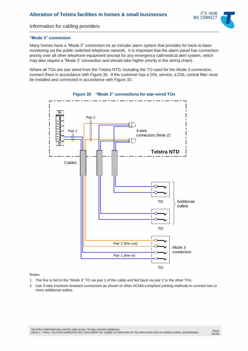
(f) rearrange a star-wired installation to support a single-ended, bus-wired or “Mode 3” configuration for
connection of, for example, a digital subscriber line (DSL) service and/or a monitored security alarm
or a personal response (emergency call/medical alert) system
(g) replace, relocate or otherwise alter the indoor lead-in cabling for any purpose including, but not
limited to, building alterations or to improve the performance of a digital subscriber line (DSL)
service
(h) disconnect, replace or relocate a changeover (C/O) switch connected to Telstra’s lead-in cabling
(i) install, relocate, replace or, under certain conditions, remove a centralised DSL filter (“central filter”
or “remote splitter”) connected to Telstra’s lead-in cabling
(j) install a Telstra network termination device (NTD) or change a line module in an existing NTD
(k) for Telstra lead-in cabling not exceeding a total capacity of ten (10) pairs and which does not
terminate on a customer MDF, disconnect underground or aerial lead-in cabling at the external
surface of the building for the purpose of renovation, demolition or relocation of the building
(l) use Telstra lead-in poles to support customer cabling.
The above activities may be performed independently or concurrently.
Alteration of Telstra facilities in homes & small businesses
Information for cabling providers
TELSTRA CORPORATION LIMITED (ABN 33 051 775 556) | ISSUED 26/08/2013 ISSUE 4 – FINAL | TELSTRA UNRESTRICTED | DOCUMENT NO. 012882 | ALTERATION OF TELSTRA FACILITIES IN HOMES & SMALL BUSINESSES
PAGE 12/193
3.4 Activities not authorised
This Document does not authorise a cabling provider to do any of the following:
(a) use or alter any part of the underground or aerial Telstra lead-in cabling between the property entry
point and the building other than disconnect cabling not exceeding a total capacity of 10 pairs at the
building for the purpose described in 3.3 (k)
(b) connect or reconnect any underground or aerial lead-in cabling that has been cut at the external
surface of the building for the purpose described in 3.3 (k) unless the lead-in cabling has been cut
during building renovation for the eventual purpose of installing a Telstra NTD under 3.3 (j)
(c) disconnect the Telstra lead-in cable and leave it permanently disconnected from any customer-
accessible TO other than where necessary for the purpose described in 3.3 (k)
(d) totally remove Telstra’s facilities from the building other than for the purpose described in 3.3 (k)
(e) alter or disconnect any Telstra lead-in cabling exceeding a capacity of 10 pairs
(f) alter or disconnect any Telstra payphone installation
(g) alter or disconnect any coaxial cabling used to supply a Telstra BigPond Cable broadband service
or a FOXTEL pay TV service
(h) alter or disconnect any Telstra optical fibre cabling
(i) alter or disconnect any Telstra lead-in cabling in a power generating station or a high voltage
distribution substation
(j) alter or disconnect any Telstra lead-in cabling in a hazardous area (explosive atmosphere) as
defined in Australian Standard AS/CA S009
(k) alter Telstra lead-in cabling or the first TO (“first socket”) where any Telstra network device or
equipment described in 4.2.4 is installed at the first TO
(l) star wire an additional TO from an existing connection block/box or joint in Telstra’s lead-in cabling
(other than a Telstra NTD), or install a new terminal block/box or joint (other than a Telstra NTD) in
the lead-in cabling for the purpose of star-wiring TOs
(m) connect Telstra’s lead-in cable on a home distributor or home networking box
(n) connect Telstra’s lead-in cable on any customer MDF, or disconnect or alter any Telstra lead-in
cabling that terminates on a customer MDF.
(o) disconnect or remove any Telstra NTD so as to change the network boundary from the NTD to the
first TO “(first socket”) or any other connection point
(p) disconnect or remove any centralised DSL filter (“central filter” or “remote splitter”) connected to
Telstra’s lead-in cabling or provided in a line module within a Telstra NTD other than to replace it
with another type of filter approved by Telstra unless its disconnection or removal is essential to the
proper functioning of a proprietary high-speed data service
(q) disconnect Telstra lead-in cabling for the purpose of migrating services from Telstra’s copper
twisted pair network to a different telecommunications network technology such as FTTP (Fibre To
The Premises), fixed wireless or satellite, e.g. the National Broadband Network (NBN).
Note: For safety reasons, the copper lead-in cable must be isolated from the internal copper cabling connected to the FTTP, fixed wireless or satellite equipment ports. However, permanent disconnection of the Telstra lead-in cabling would be contrary to 3.4 (c). A separate agreement is required between Telstra and the relevant carrier or carriage service provider to allow permanent disconnection of Telstra lead-in cabling.
3.5 Contacting Telstra to carry out the above work
Telstra contact details for requesting work described in 3.4 are provided in Section 16.
Charges apply for the alteration, repair or disconnection of existing Telstra facilities. However, Telstra’s
applicable new service connection fee may cover some or all of the cost of the installation of Telstra
facilities for the purpose of supplying a new Telstra service.
Alteration of Telstra facilities in homes & small businesses
Information for cabling providers
TELSTRA CORPORATION LIMITED (ABN 33 051 775 556) | ISSUED 26/08/2013 ISSUE 4 – FINAL | TELSTRA UNRESTRICTED | DOCUMENT NO. 012882 | ALTERATION OF TELSTRA FACILITIES IN HOMES & SMALL BUSINESSES
PAGE 13/193
4 INTRODUCTION
4.1 Background
Telstra supplies telecommunications network services to customers under the terms and conditions set
out in the relevant service agreement, e.g. Telstra’s Standard Form Of Agreement (published as “Our
Customer Terms” at http://www.telstra.com.au/customer-terms/).
In order to supply network services, Telstra must install some facilities in the customer’s premises and
must maintain these facilities for continuance of the service or supply of subsequent services. Telstra
has some reservations about allowing cabling providers to alter Telstra facilities for the following
reasons:
Telstra has a statutory obligation to supply standard telephone services within a strict price control
regime and is also subject to regulatory controls such as the Customer Service Guarantee (CSG)
Standard. The CSG Standard imposes financial penalties on carriers if certain performance
standards for connection and repair of standard telephone services are not met.
In certain circumstances, Telstra may install lightning surge suppressors at the customer’s building to
reduce the risk of customer injury if the customer is using the service during any thunderstorm
activity. If these surge suppressors are accidentally bypassed or disabled during cabling work, this
may put the customer’s safety at risk. On a national average, about 20-25% of home installations
connected to Telstra copper twisted pair networks have surge suppressors installed. In some regions
(e.g. Darwin), the figure is 100%, whereas in other regions it is virtually 0%.
In some cases, Telstra may install devices or equipment at the customer’s premises that are
essential to the operation and performance of the service or for maintaining the integrity of the public
telecommunications network.
Telstra has no legal obligation to authorise cabling providers to alter Telstra facilities within customer
premises. However, it is not Telstra’s intention to impede cabling work that may include alterations to
Telstra’s network facilities if, in Telstra’s opinion, a cabling provider is capable of carrying out such
alterations without adversely affecting Telstra or the customer. Accordingly, Telstra will authorise cabling
providers to make limited alterations to its facilities in or on a customer’s building under the specified
terms and conditions.
4.2 Rationale for limiting authorisation
4.2.1 General
The underlying reasons why Telstra will only authorise certain work under certain conditions are
explained in 4.1. The rationale behind the technical constraints imposed by this Document is explained
in 4.2.2 to 4.2.4.
4.2.2 Cabling alterations limited to cabling in or on the building
For homes and small businesses where the network boundary is the first TO (“first socket”) inside the
building, any Telstra lightning surge suppressors or other hard-wired electronic devices are usually
located within a box on the external wall of the building at or near the building entry point. To minimise
the risk of accidental disablement of such devices, this Document limits authorised alterations to work
inside the building or to specific work on the external wall of the building.
4.2.3 Materials and practices must be to Telstra’s standards
Telstra specifies the use of certain materials and practices within the confines of its network (i.e. up to
and including the network boundary) because Telstra must maintain these facilities. Telstra workers
may only carry these standard materials for repair work or alterations. Thus it is a general condition of
any Telstra authorisation contained herein for the cabling provider to use the same materials and
practices as Telstra would normally use on its side of the network boundary.
Alteration of Telstra facilities in homes & small businesses
Information for cabling providers
TELSTRA CORPORATION LIMITED (ABN 33 051 775 556) | ISSUED 26/08/2013 ISSUE 4 – FINAL | TELSTRA UNRESTRICTED | DOCUMENT NO. 012882 | ALTERATION OF TELSTRA FACILITIES IN HOMES & SMALL BUSINESSES
PAGE 14/193
4.2.4 Alterations not authorised where network equipment is installed at the first point
In some cases, a Telstra network device or equipment may be installed at the first TO (“first socket”) or
first equipment connection point (“first point”). Disconnection or incorrect wiring of such devices or
equipment may render the customer’s service(s) inoperative or unsafe and may damage the Telstra
equipment or the Telstra network.
In such cases, alteration of Telstra facilities is not authorised.
Alteration of Telstra lead-in cabling or network boundary facilities is not authorised where any the
following devices or equipment is connected at the first point (whether hard-wired or plug-connected):
(a) a Telstra payphone;
(b) a functioning (in-service) ISDN NT1 or ANT1 (Analogue NT1);
(c) any type of line multiplexing, line conditioning or line conversion equipment (e.g. a small pair-gain
system);
(d) a line impedance matching unit or RF noise filter (usually a discrete component or a printed circuit
board hard-wired to the first TO);
(e) a surge suppression device hard-wired to the first TO.
4.3 Legal issues
4.3.1 The network boundary
Where the Telstra lead-in cable is not connected to a customer MDF or a Telstra NTD, the network
boundary for each line supplied to a building will be the first TO (“first socket”) connected to that line after
the building entry point or, in some cases, an obsolete fixed wallphone or other, obsolete, hard-wired
telephone. The first TO will be the network boundary with the vast majority of single dwellings
throughout Australia. In such cases, Telstra accepts responsibility for installation and repair of a
standard Telstra telephone service up to, and including, the first TO.
Note: For a detailed description of the network boundary, refer to Appendix J of Australian Standard AS/CA S009, Installation requirements for customer cabling (Wiring rules).
Prior to “deregulation” of premises cabling in 1989, it was common practice in some areas to star wire
TOs from a connection device or joint in the lead-in cable. In such cases, each star-wired TO is
potentially the network boundary for the cable terminated on it. In the deregulated environment, this
creates problems for both Telstra and the cabling provider, but Telstra is not obliged to reconfigure
existing star-wired installations.
This Document does not legally change the network boundary from the first TO to the building entry point
or to any intermediate connection device or joint in the lead-in cabling — the network boundary is
determined by legislation and remains at the first TO, NTD or MDF, as applicable. What this Document
does is authorise a cabling provider to make limited changes to Telstra’s network facilities, including
changing the location of the network boundary at the building (e.g. changing the position of the first TO
from one part of the building to another, or changing the network boundary from the first TO to a Telstra
NTD).
4.3.2 Carrier ownership or operation of facilities and unlawful tampering or interference with
those facilities
All telecommunications facilities owned or operated by a licensed carrier or a carriage service provider
(e.g. Telstra) are protected by various laws, whether or not they are located on the carrier’s property,
public property or private property (e.g. in customer premises). A summary of applicable laws follows.
4.3.3 Telecommunications Act 1997
In accordance with Clause 47 of Schedule 3 of the Telecommunications Act 1997, Telstra continues to
have ownership of facilities that it provides in customer premises even if they have become fixtures.
Alteration of Telstra facilities in homes & small businesses
Information for cabling providers
TELSTRA CORPORATION LIMITED (ABN 33 051 775 556) | ISSUED 26/08/2013 ISSUE 4 – FINAL | TELSTRA UNRESTRICTED | DOCUMENT NO. 012882 | ALTERATION OF TELSTRA FACILITIES IN HOMES & SMALL BUSINESSES
PAGE 15/193
4.3.4 Criminal Code 1995 (Cth)
A person is guilty of an offence under Section 474.6 of the Criminal Code 1995 (Cth) if:
the person tampers or interferes with a facility owned or operated by a carrier or a carriage service
provider; or
the person tampers or interferes with a facility owned or operated by a carrier or a carriage service
provider and this conduct results in hindering the normal operation of a carriage service supplied by a
carriage service provider.
Note: The main distinction between a carrier and a carriage service provider is that a carrier owns the network infrastructure over which carriage services are supplied while a carriage service provider supplies carriage services using the network of one or more carriers. Telstra is both a carrier and a carriage service provider.
Each offence carries the risk of a substantial fine and/or imprisonment upon conviction. However,
Section 474.3 of the Criminal Code 1995 (Cth) makes provision for a person to do any thing for or on
behalf of a carrier or a carriage service provider. Through this Document, Telstra authorises a registered
cabling provider to alter certain Telstra facilities, on the specified terms and conditions, under Section
474.3 of the Criminal Code 1995 (Cth).
4.3.5 Common law
Common law is “unwritten law” based on custom or court decision. Under the common law of
negligence, persons owe Telstra a duty of care to take all reasonable precautions not to damage
Telstra’s facilities. Telstra has a right to bring a claim against a cabling provider who interferes with or
damages Telstra’s facilities or services that results in Telstra suffering loss.
4.3.6 What does Telstra own or operate?
Telstra owns or operates its facilities up to Telstra’s network boundary. Telstra may also own facilities on
the customer side of the network boundary, for example:
a telephone or other customer equipment rented from Telstra;
an ISDN NT1 or other network termination unit;
customer cabling provided by Telstra at Telstra’s cost to fulfil a service agreement with a customer or
to discharge a statutory service obligation.
Generally, Telstra-owned equipment or cabling on the customer side of the network boundary will be
identified as Telstra property, e.g. labelled or stamped “Property of Telstra”. Other forms of product
labelling (e.g. simply "Telstra") are brand markings and do not necessarily imply Telstra ownership (e.g.
customer equipment sold outright at department stores or Telstra shops).
4.3.7 Performance of cabling work
A person who installs or maintains cabling for connection to a telecommunications network (“cabling
work”) must comply with the Telecommunications Act 1997. The person must be registered to perform
cabling work by an ACMA-accredited body (a “cabling registrar”). It is a condition of the registration for
the person to comply with the wiring rules (Australian Standard AS/CA S009).
Clause 5.13 of AS/CA S009:2013 prohibits a cabling provider from moving, removing or altering any
lead-in cabling or network boundary facilities without the prior written authorisation of the carrier.
However, the Note to Clause 5.13 of AS/CA S009:2013 clarifies that if a carrier publishes a document
authorising cabling providers to alter its facilities (such as this Document), such a document will be taken
to be the prior written authorisation of the carrier as long as any terms and conditions set out in the
document are adhered to by the cabling provider.
4.3.8 Telstra may revoke or vary authorisation
Telstra reserves the right to cancel this Document, to revoke or vary any authorisation conveyed in this
Document, or to vary the terms and conditions prescribed in this Document, either generally or
selectively, at any time without notice in its absolute discretion.
Alteration of Telstra facilities in homes & small businesses
Information for cabling providers
TELSTRA CORPORATION LIMITED (ABN 33 051 775 556) | ISSUED 26/08/2013 ISSUE 4 – FINAL | TELSTRA UNRESTRICTED | DOCUMENT NO. 012882 | ALTERATION OF TELSTRA FACILITIES IN HOMES & SMALL BUSINESSES
PAGE 16/193
It will be the responsibility of the cabling provider to ensure that this Document has not been cancelled,
that the latest version of this Document is used, and that relevant laws, codes, standards or other
regulatory requirements are complied with.
4.3.9 Telstra “accreditation”
In 1998, Telstra started contracting out certain network tasks. Initially, Telstra directly managed the
contracting arrangements and contractors were “accredited” to perform Telstra work. This accreditation
only allowed persons to perform Telstra work assigned to them. Such accreditation did not, and does
not, authorise any person to perform any work on Telstra’s network without a Telstra “ticket of work”.
Telstra ceased “accrediting” contractors a few years later when “prime” contractors were appointed to
manage contracting work on behalf of Telstra.
Any person who holds, or believes they hold, “Telstra Accreditation” is not authorised to perform any
work on Telstra facilities other than:
a task specified in a ticket of work issued by Telstra or by one of Telstra’s approved (“prime”)
contractors; or
an activity described in this Document that any registered cabling provider is authorised to do under
the terms and conditions set out in this Document.
4.4 Interpretation
Use of the words “must”, “must not”, “shall” and “shall not” signify:
a legal obligation;
an important safety, technical or operational requirement; or
a mandatory condition of this Document.
Use of the words “should” or “should not” denote a recommendation of this Document or of a relevant
standard.
Text boxed like this contains an alert or key information.
Alteration of Telstra facilities in homes & small businesses
Information for cabling providers
TELSTRA CORPORATION LIMITED (ABN 33 051 775 556) | ISSUED 26/08/2013 ISSUE 4 – FINAL | TELSTRA UNRESTRICTED | DOCUMENT NO. 012882 | ALTERATION OF TELSTRA FACILITIES IN HOMES & SMALL BUSINESSES
PAGE 17/193
5 AUTHORISED WORK
5.1 About this section
This section describes the type of work that is authorised by Telstra and sets out the general terms and
conditions that apply to all activities plus further terms and conditions that apply to each specific activity.
If an activity is not listed, it is not authorised.
Examples of specific activities that are not authorised are listed in 3.4.
Part 2 of this Document (commencing from page 25) provides technical information to assist cabling
providers in complying with the terms and conditions of this Document.
5.2 General terms and conditions
Telstra authorises a cabling provider to do certain work on Telstra facilities, as set out in this Document,
subject to the following general terms and conditions:
(a) The person performing the cabling work (cabling provider) must be a registered cabling provider in
either the Restricted or Open category.
Note: While by law cabler registration is not required to perform work on Telstra’s side of the network boundary, Telstra requires the person to be a registered cabling provider as a condition of this Document as a measure of competency to do the work and to ensure that the requirements of the Cabling Provider Rules are met in case the work also involves any cabling activity on the customer’s
side of the network boundary.
(b) The cabling provider must ensure that he/she is familiar with all applicable legal and regulatory
requirements for the performance of this work and that he/she complies with all laws, regulations,
standards and codes of practice applicable to this work.
(c) The cabling provider acknowledges that:
(i) he/she is responsible for the restitution of faulty or substandard work if requested to do so by
Telstra or the customer;
(ii) Telstra reserves the right to seek damages from the cabling provider if Telstra incurs costs due
to any work performed by the cabling provider on Telstra’s facilities; and
(iii) Telstra retains ownership of any Telstra facilities so worked on whether re-used or replaced.
(d) The cabling provider acknowledges that he/she is not performing any work under this Document in
Telstra’s name nor is he/she a contractor or employee of Telstra. The cabling provider must not
represent or give an impression to customers or third parties that he/she is performing work as an
employee or a contractor of Telstra.
(e) The cabling provider must not seek any remuneration from Telstra for any work performed.
(f) The cabling provider agrees to indemnify Telstra against any liability, loss, damage, costs or
expenses incurred or suffered by Telstra that is caused by any act or omission of the cabling
provider whether negligent or not, or which arises from any default under the terms and conditions
of this Document.
(g) The cabling provider must not do anything that may affect the safety, integrity or proper functioning
of the Telstra network or the safety of the customer or any other person. The cabling provider must
not use substances or material deleterious to health or safety or which could adversely affect the
functioning of the Telstra network.
(h) The cabling provider must ensure that he/she does not cause unnecessary detriment,
inconvenience or damage to Telstra, the customer or a third party.
(j) The cabling provider must not do any act or thing that is prejudicial to the goodwill, commercial
reputation or overall public image of Telstra.
(k) The cabling provider must keep proper records of the work performed under this Document.
Alteration of Telstra facilities in homes & small businesses
Information for cabling providers
TELSTRA CORPORATION LIMITED (ABN 33 051 775 556) | ISSUED 26/08/2013 ISSUE 4 – FINAL | TELSTRA UNRESTRICTED | DOCUMENT NO. 012882 | ALTERATION OF TELSTRA FACILITIES IN HOMES & SMALL BUSINESSES
PAGE 18/193
(l) Notwithstanding anything contained in this Document, the cabling provider must take all reasonable
steps to ensure that lightning surge suppressors or any equipment that may be necessary for the
safety and proper functioning of the installation are not bypassed or disconnected.
(m) The cabling provider must not create any star-wired connections from an intermediate connection
point in the lead-in cabling, i.e. between the property entry point and the first TO, unless the
intermediate connection point is:
(i) a centralised DSL filter (“central filter” or “remote splitter”) provided in accordance with 5.8 of
this Document; or
(ii) a Telstra NTD provided in accordance with 5.9 of this Document.
(n) The cabling provider must not render any Telstra installation unusable, e.g. by removing the Telstra
cabling or not terminating the Telstra lead-in cable at a TO that is readily accessible by the
customer, unless this is necessary for the purpose of renovation, demolition or relocation of the
building.
(o) The cabling provider must not connect Telstra lead-in cable to:
(i) a customer MDF; or
(ii) a home networking box or a patch panel of any description other than by the means described
in Section 12.
(p) Any new cabling to the first TO must be installed in a manner that enables safe access and/or
replacement of such cabling by Telstra workers subsequent to its installation.
(q) Where the location of the network boundary is changed, the customer must be notified immediately
in writing of this fact. The notification must be substantially in the form described in Section 15.
(r) Any waste material (e.g. used wire, cable, conduit, etc.) must be safely and properly disposed of in
accordance with applicable laws.
5.3 Replacement of the first TO
Telstra authorises a cabling provider to replace the first TO, i.e. the network boundary, with another TO
subject to the general terms and conditions of 5.2 and the following:
(a) The TO shall comply with Section 9.
5.4 Relocation of the first TO
Telstra authorises a cabling provider to relocate the first TO, i.e. the network boundary, to another
location subject to the general terms and conditions of 5.2 and the following:
(a) The TO shall only be relocated to another position in the same building.
(b) The TO location shall comply with 9.5.1.
(c) The TO, if replaced, shall comply with Section 9.
(d) The TO shall be cabled in accordance with Section 8.
(e) No alterations shall be made to any part of the outdoor cabling except for:
(i) one-for-one replacement of conductor terminations or connectors at an existing outdoor
connection device for the sole purpose of disconnecting the old cable for the first TO and
reconnecting the replacement cable;
(ii) re-routing of the TO cabling on the outside surface of the building where indoor cabling is not
practicable;
(iii) the relocation or replacement of an existing outdoor centralised DSL filter (“central filter” or
“remote splitter”) in accordance with 5.8;
(iv) the installation of a Telstra NTD in accordance with 5.9; or
(v) disconnection of the cabling for the purpose of renovation, demolition or relocation of the
building in accordance with 5.10.
Alteration of Telstra facilities in homes & small businesses
Information for cabling providers
TELSTRA CORPORATION LIMITED (ABN 33 051 775 556) | ISSUED 26/08/2013 ISSUE 4 – FINAL | TELSTRA UNRESTRICTED | DOCUMENT NO. 012882 | ALTERATION OF TELSTRA FACILITIES IN HOMES & SMALL BUSINESSES
PAGE 19/193
5.5 Fixed Telstra wallphone or other hard-wired telephone
5.5.1 Replacement or relocation
Telstra authorises a cabling provider to replace an obsolete fixed Telstra wallphone or other hard-wired
Telstra telephone (excluding a payphone) with a TO for the purpose of connecting other customer
equipment, or to relocate the existing telephone, subject to the general terms and conditions of 5.2 and
the following:
(a) If the replacement TO is to be the first TO, the TO shall comply with Section 9.
(b) If the existing telephone or replacement TO is to be relocated and is to be reconnected as the first
telephone or TO after the building entry point, it shall be installed in accordance with the
requirements of 5.4.
(c) If the existing telephone is replaced and is no longer required, the cabling provider shall advise the
customer to return the telephone to a Telstra shop or other Telstra telephone collection point to
ensure that charging of a rental fee for the telephone is discontinued.
5.5.2 Disconnection
Telstra authorises a cabling provider to disconnect an obsolete fixed Telstra wallphone or other hard-
wired Telstra telephone (excluding a payphone) if it is no longer required, subject to the general terms
and conditions of 5.2 and the following:
(a) If the aforementioned telephone is the first telephone connected to the line after the building entry
point, it shall be replaced with a TO that complies with Section 9.
(b) If the replacement TO is the first TO connected to the line after the building entry point and the
required location of the TO is different to the location of the aforementioned telephone, it shall be
cabled in accordance with the requirements of 5.4.
(c) The cabling provider shall advise the customer to return the aforementioned telephone to a Telstra
shop or other Telstra telephone collection point to ensure that charging of a rental fee for the
telephone is discontinued.
5.6 Star-wired TOs
5.6.1 TO alterations
Telstra authorises a cabling provider to relocate a TO that has been star wired from a connection
block/box, lightning protector block or other joint installed in the lead-in cabling, subject to the general
terms and conditions of 5.2 and either of the following:
(a) the TO shall be relocated without disturbing the aforementioned connection block/box, lightning
protector block or joint; or
(b) the building cabling shall be reconfigured in accordance with 5.6.3.
5.6.2 Additional TOs
Telstra authorises a cabling provider to cable an additional TO from a star-wiring point in the lead-in
cabling subject to the general terms and conditions of 5.2 and either of the following:
(a) The cabling shall be installed in accordance with 5.6.3 such that the star-wiring point is connected
on the “customer” side of the first TO.
Note: The additional TO could be cabled from one of the existing star-wired TOs, in which case reconfiguration of the installation would not be necessary.
(b) A Telstra NTD shall be installed in accordance with 5.9 such that the star wiring point and the
additional TO are connected on the “customer” side of the NTD.
Alteration of Telstra facilities in homes & small businesses
Information for cabling providers
TELSTRA CORPORATION LIMITED (ABN 33 051 775 556) | ISSUED 26/08/2013 ISSUE 4 – FINAL | TELSTRA UNRESTRICTED | DOCUMENT NO. 012882 | ALTERATION OF TELSTRA FACILITIES IN HOMES & SMALL BUSINESSES
PAGE 20/193
5.6.3 Reconfiguration of the wiring
Telstra authorises a cabling provider to rearrange a star-wired installation to support a single-ended,
bus-wired or “Mode 3” configuration for connection of a DSL service, monitored security alarm, personal
response (emergency call/medical alert) system, etc., subject to the general terms and conditions of 5.2
and the following:
(a) the wiring arrangement shall be altered in accordance with 8.5 (non-DSL) or 10.3.5.4 (DSL), as
applicable;
(b) the TO connected as the first TO for each service shall comply with Section 9; and
(c) the first TO shall be cabled in accordance with the requirements of 5.4.
5.7 C/O (changeover) switch
5.7.1 Alteration
Telstra authorises a cabling provider to disconnect, relocate or replace an existing C/O switch connected
to Telstra’s lead-in cabling subject to the general terms and conditions of 5.2 and the following:
(a) Where the C/O switch is disconnected, Telstra’s lead-in cable shall be terminated on a TO that
complies with Section 9.
(b) If the location of the replacement TO is different to the location of the C/O switch, it shall be cabled
in accordance with the requirements of 5.4.
(c) If the C/O switch is relocated, it shall be cabled in accordance with Section 8.
(d) If the C/O switch is replaced and is to remain connected on Telstra’s side of the first TO, it shall be
replaced by a double pole C/O switch that complies with 8.7.
5.7.2 Installation
Telstra does not authorise a cabling provider to install a new C/O switch in Telstra’s lead-in cabling.
Where a new C/O switch is to be installed:
(a) the C/O switch shall be installed on the customer side of the first TO in accordance with 8.7.3; or
(b) a Telstra NTD shall be installed in accordance with 5.9 such that the C/O switch is connected on the
customer side of the NTD.
Note: Telstra is phasing out the use of C/O switches connected to lead-in cabling. Refer to 8.7.4.
Telstra authorises a cabling provider to replace or relocate a centralised DSL filter (“central filter” or
“remote splitter”) that has been installed in the lead-in cabling, subject to the general terms and
conditions of 5.2 and the following:
(a) The filter shall only be relocated to another position in the same building.
(b) The filter, if replaced, shall comply with 10.3.3 (indoor filter) or 10.3.4 (outdoor filter).
(c) The filter shall be located and installed in accordance with 10.3.
5.8.2 Installation
Telstra authorises a cabling provider to install a centralised filter (“central filter” or “remote splitter”) in the
lead-in cabling subject to the general terms and conditions of 5.2 and the following:
(a) The filter shall be located in the same building as the DSL modem.
(b) The filter used shall comply with 10.3.3 (indoor filter) or 10.3.4 (outdoor filter).
(c) The filter shall be located and installed in accordance with 10.3.
Alteration of Telstra facilities in homes & small businesses
Information for cabling providers
TELSTRA CORPORATION LIMITED (ABN 33 051 775 556) | ISSUED 26/08/2013 ISSUE 4 – FINAL | TELSTRA UNRESTRICTED | DOCUMENT NO. 012882 | ALTERATION OF TELSTRA FACILITIES IN HOMES & SMALL BUSINESSES
PAGE 21/193
5.9 Telstra NTD
5.9.1 Alteration
Telstra authorises a cabling provider to replace an existing obsolete Telstra NTD with a new Telstra
NTD, or replace an NTD line module with another NTD line module, subject to the general terms and
conditions of 5.2 and the following:
(a) The NTD shall not be replaced if the Telstra lead-in cabling has more than a total of 5 pairs (e.g.
more than 1 x 5-pair cable or 2 x 2-pair cables).
(b) The NTD to be used shall be the NTD described in 11.1.
(c) The NTD shall be installed in accordance with 11.4.
(d) An existing DSL line module shall not be replaced with a non-DSL line module except under the
conditions described in 11.3.1 (h) and (i).
(e) Telstra shall be notified of the NTD alteration within 14 days in accordance with 11.4.6, so that
Telstra can update its records.
5.9.2 Installation
Telstra authorises a cabling provider to install a Telstra NTD where the existing network boundary is the
first TO or a fixed telephone described in 4.3.1, subject to the general terms and conditions of 5.2 and
the following:
(a) The NTD shall only be installed if the Telstra lead-in cabling has no more than a total of 5 pairs (e.g.
no more than 1 x 5-pair cable or 2 x 2-pair cables).
(b) The NTD shall only be used to connect a single household (inclusive of a “home office” or “granny
flat”) or a single office/business.
(c) The NTD shall not be used to connect a cable from another carrier’s network other than a cable
connected between the customer side of that carrier’s NTD, first TO, fixed wireless terminal,
satellite terminal or a customer MDF and the customer side of the Telstra NTD.
(d) The NTD shall be located on the external wall of the same building in which the telecommunications
service(s) will be used by the customer and shall not be installed at any point away from the
building (e.g. at a fence, pole or any other detached structure).
(e) The NTD to be used shall be the NTD described in 11.1.
(f) The NTD shall be installed in accordance with 11.4.
(g) The customer shall be informed of the existence of the NTD in accordance with 11.4.5.
(h) Telstra shall be notified of the NTD installation within 14 days in accordance with 11.4.6.
5.10 Disconnection of Telstra lead-in cabling
Telstra authorises a cabling provider to disconnect underground or aerial Telstra lead-in cabling at the
external surface of a building for the purpose of renovation, demolition or relocation of the building,
subject to the general terms and conditions of 5.2 and the following:
(a) The lead-in cable shall only be disconnected if the total capacity of the lead-in cabling does not
exceed 10 pairs and does not terminate on a customer MDF.
(b) If a span of aerial lead-in cable is detached from the building, it shall not be reattached to the
building by any person other than Telstra.
(c) If the underground or aerial lead-in cabling is disconnected for the purpose of demolition or
relocation of the building, it shall not be reconnected to a new or relocated building by any person
other than Telstra.
(d) If the underground or aerial lead-in cabling is disconnected for the purpose of building renovation,
it shall not be reconnected by any person other than Telstra except as allowed under 7.4.1 (b) or
7.4.1 (c), as applicable.
(e) The lead-in cabling shall be disconnected from the building in accordance with 7.4.1.
Alteration of Telstra facilities in homes & small businesses
Information for cabling providers
TELSTRA CORPORATION LIMITED (ABN 33 051 775 556) | ISSUED 26/08/2013 ISSUE 4 – FINAL | TELSTRA UNRESTRICTED | DOCUMENT NO. 012882 | ALTERATION OF TELSTRA FACILITIES IN HOMES & SMALL BUSINESSES
PAGE 22/193
5.11 Use of Telstra lead-in poles for customer cabling
Telstra authorises a cabling provider to use Telstra lead-in poles to support aerial customer cabling
subject to the general terms and conditions of 5.2 and the following:
(a) Only poles that are located within the boundaries of the customer’s premises shall be used.
(b) The poles shall only be used if sufficient pole height is available to install the customer cabling in
accordance with the requirements of the wiring rules (Australian Standard AS/CA S009) while
maintaining the required separation from the Telstra aerial cable and fittings in accordance with
7.4.2.
(c) The customer cabling shall be installed and maintained at the customer’s cost, including transfer of
the cabling to any pole subsequently condemned and replaced by Telstra.
(d) The aerial customer cabling shall be installed in accordance with 7.4.2.
Note: For safety reasons, Telstra will not use customer-owned poles to support Telstra cabling but will allow Telstra-owned poles erected at the customer’s cost (see 7.3) to be used to support the customer’s aerial LV power mains or customer cabling. Telstra should be advised of this requirement in advance of commencement of pole installation so that Telstra can ensure that the poles used are of sufficient height to support additional cables. The customer will usually be required to pay any cost difference between Telstra’s standard poles and longer poles if extra pole length is required. Refer to Section 7 for more information.
Alteration of Telstra facilities in homes & small businesses
Information for cabling providers
TELSTRA CORPORATION LIMITED (ABN 33 051 775 556) | ISSUED 26/08/2013 ISSUE 4 – FINAL | TELSTRA UNRESTRICTED | DOCUMENT NO. 012882 | ALTERATION OF TELSTRA FACILITIES IN HOMES & SMALL BUSINESSES
PAGE 23/193
PART 2
Technical Information
Alteration of Telstra facilities in homes & small businesses
Information for cabling providers
TELSTRA CORPORATION LIMITED (ABN 33 051 775 556) | ISSUED 26/08/2013 ISSUE 4 – FINAL | TELSTRA UNRESTRICTED | DOCUMENT NO. 012882 | ALTERATION OF TELSTRA FACILITIES IN HOMES & SMALL BUSINESSES
PAGE 24/193
(INTENTIONALLY BLANK)
Alteration of Telstra facilities in homes & small businesses
Information for cabling providers
TELSTRA CORPORATION LIMITED (ABN 33 051 775 556) | ISSUED 26/08/2013 ISSUE 4 – FINAL | TELSTRA UNRESTRICTED | DOCUMENT NO. 012882 | ALTERATION OF TELSTRA FACILITIES IN HOMES & SMALL BUSINESSES
PAGE 25/193
6 DESCRIPTION OF BASIC TELSTRA INSTALLATIONS
6.1 General
Telstra lead-in cabling to the customer’s building may be underground or aerial. Typical underground
and aerial installations are illustrated in Figure 1.
Figure 1 Typical residential or small business installations within the scope of this Document
(a) Underground lead-in cabling to the building
Footway(typical)
Fence
entry pointProperty
TO
Buildingentry point
Connection box(Note 1)
Underground joint
FirstTO
Additional
'Carrier side' of thenetwork boundary
'Customer side' of thenetwork boundary
Customerequipment
Lead-incabling
Customercabling
Networkboundary
(b) Aerial lead-in cabling to the building
Footway(typical)
Fence
entry pointProperty
TO
Buildingentry point
Connection box
Lead-incabling
(Note 1)
FirstTO
Additional
Pole
Aerial joint
'Carrier side' of thenetwork boundary
'Customer side' of thenetwork boundary
Customerequipment
Customercabling
Networkboundary
Notes:
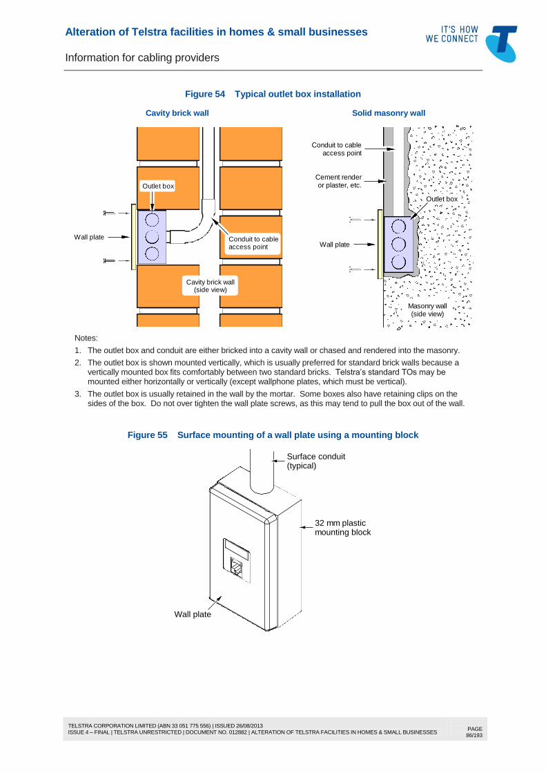
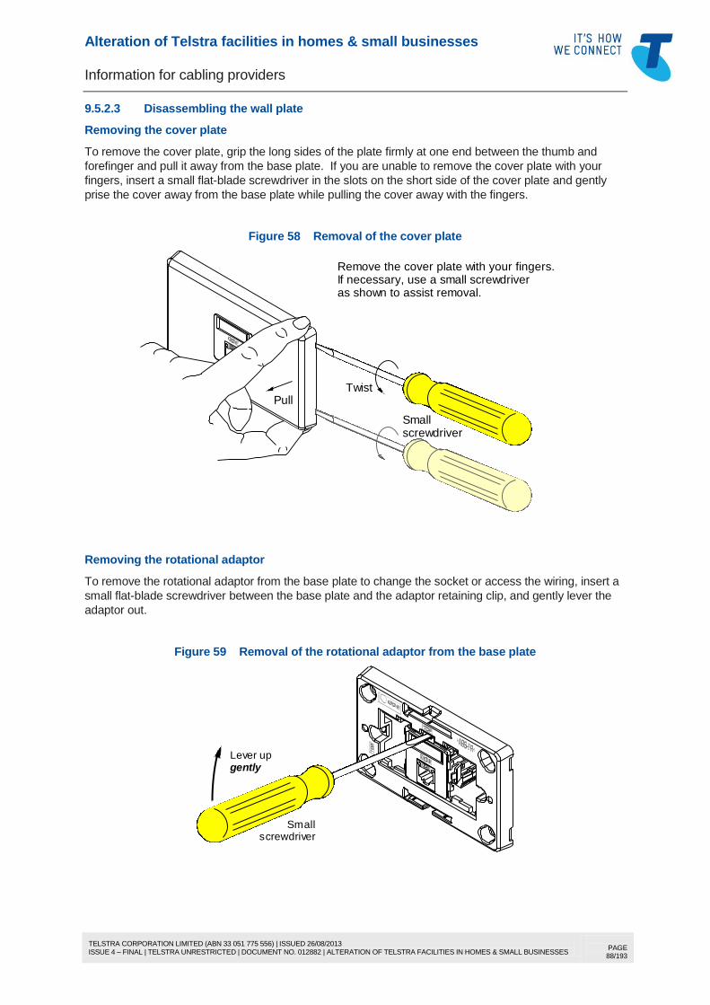
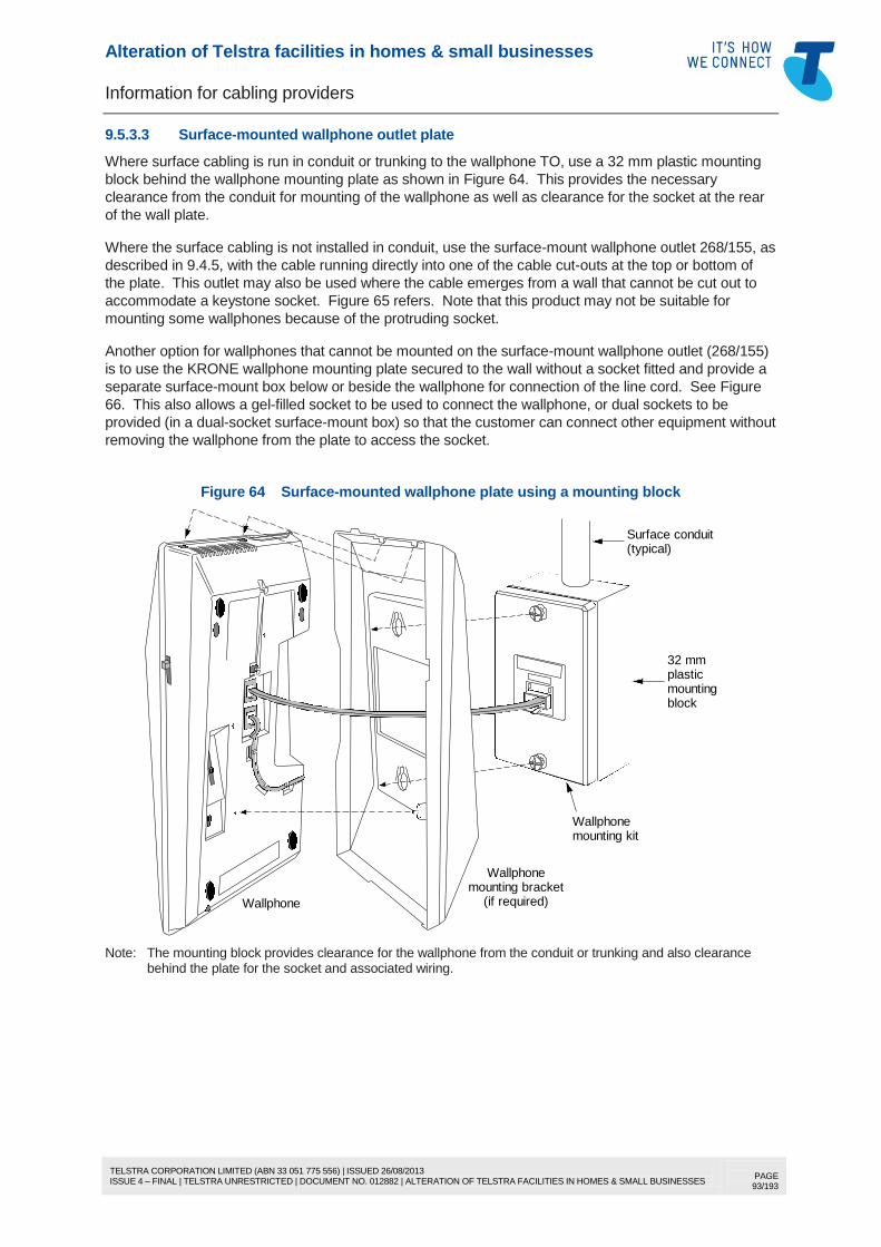
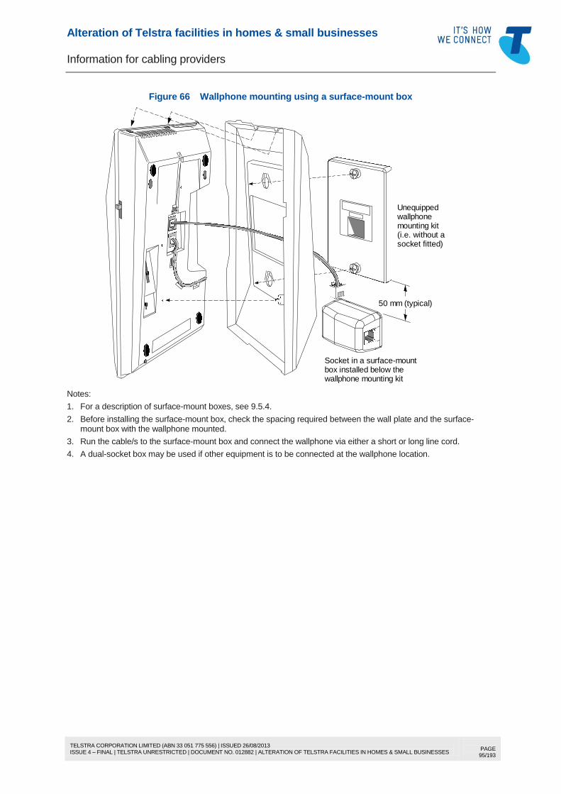
1. With new residential installations and some small business installations, the Telstra lead-in cable is provided in two sections — the outdoor cabling from the property entry point to an intermediate connection box on the outside of the building, and the indoor cabling from the connection box to the first telecommunications outlet (TO) inside the building. With older installations, there may not be an intermediate connection box in the lead-in cable.
2. The network boundary is the first TO (“first socket”) connected to the line after the building entry point. A connection box provides a Telstra cable jointing and test point, plus a point for the installation of lightning surge suppressors, and is not a network boundary point unless it is embossed “NETWORK TERMINATION DEVICE”. Refer to Section 11 and Telstra Document No. 012688 for Telstra Network Termination Device details.
Alteration of Telstra facilities in homes & small businesses
Information for cabling providers
TELSTRA CORPORATION LIMITED (ABN 33 051 775 556) | ISSUED 26/08/2013 ISSUE 4 – FINAL | TELSTRA UNRESTRICTED | DOCUMENT NO. 012882 | ALTERATION OF TELSTRA FACILITIES IN HOMES & SMALL BUSINESSES
PAGE 26/193
6.2 Lightning surge suppression
In circumstances where the customer may be at risk of injury if using the telephone during lightning
activity, Telstra may install surge suppressors for the protection of end-users. Telstra calls this
“customer lightning protection” (CLP).
Where surge suppression is installed, it needs to be located such that the length of the equipotential
bonding conductor between the surge suppressors and the building electrical earthing system is as short
and direct as possible (preferably no longer than 1.5 m) and, in any case, does not exceed 10 m. Where
the lead-in cabling runs to the same side of the building as the electrical switchboard, the suppressors
are usually installed in the Telstra connection box at or near the building entry point.
However, if the electrical switchboard is located on the opposite side of the building, “lead-in extension
cabling” must be run to a connection box on that side of the building, in which the surge suppressors are
installed and bonded to the electrical earthing system, before the lead-in cable continues to the first TO.
This means there may be two Telstra connection boxes in the lead-in cabling — one at the building entry
point and one near the electrical switchboard to house the surge suppressors. This arrangement is
illustrated in Figure 2, Figure 3 and Figure 4.
In such cases, connection box 1 and the wiring between it and connection box 2 indicated in Figure 2
must not be disturbed. Telstra only authorises alterations to the wiring between connection box 2 and
the first TO.
Figure 2 Lightning surge suppression installed on the far side of the building to the point where
the lead-in cabling meets or enters the building
Networkboundary
Buildingentry point
Connectionbox 1
TOAdditional
PoleLead-in(Note 1)
Electricalswitchboard
Equipotentialbonding conductorLead-in
This cabling must NOTbe disturbed (Note 4)
First TO
Connection box 2
Lead-in
Notes:
1. The outdoor part of the Telstra lead-in cabling may be aerial (as shown above) or underground. The need for the installation of Telstra lightning surge suppressors is not confined to aerial lead-ins.
2. Connection box 1 is installed for jointing the outdoor part of the lead-in cable to the indoor part of the lead-in cable. Connection box 2 is required to house and connect the surge suppression devices and the equipotential bonding conductor to the building electrical earthing system. Current Telstra practice is to use significantly heavier gauge cable — or double up the cable pairs — between connection box 1 and connection box 2 where this cable passes through the building. This is done to minimise the risk of cable ignition if there is a HV power fault or contact with a HV power line in the Telstra network or at the customer’s premises.
3. The network boundary is the first TO connected to the line inside the building. Neither connection box 1 nor connection box 2 is a network boundary point unless embossed “NETWORK TERMINATION DEVICE”. Refer to Section 11 and Telstra Document No. 012688 for Telstra Network Termination Device details.
4. Connection box 1 and the wiring between connection box 1 and connection box 2 must not be disturbed.
Telstra only authorises alterations to the wiring between connection box 2 and the first TO.
Alteration of Telstra facilities in homes & small businesses
Information for cabling providers
TELSTRA CORPORATION LIMITED (ABN 33 051 775 556) | ISSUED 26/08/2013 ISSUE 4 – FINAL | TELSTRA UNRESTRICTED | DOCUMENT NO. 012882 | ALTERATION OF TELSTRA FACILITIES IN HOMES & SMALL BUSINESSES
PAGE 27/193
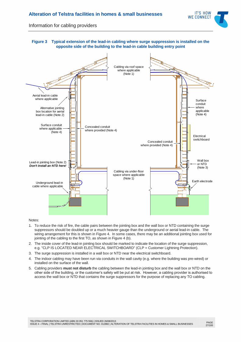
Figure 3 Typical extension of the lead-in cabling where surge suppression is installed on the
opposite side of the building to the lead-in cable building entry point
Don't install an NTD here!(Note 3)or NTD
Electrical
Surfaceconduit
Concealed conduitwhere provided (Note 4)
Aerial lead-in cablewhere applicable
Underground lead-incable where applicable
Concealed conduitwhere provided (Note 4)
where applicableCabling via roof space
Alternative jointing
lead-in cable (Note 2)box location for aerial
whereapplicable(Note 4)
switchboard
Earth electrode
space where applicableCabling via under-floor
Surface conduitwhere applicable
(Note 1)
(Note 1)
Wall boxLead-in jointing box (Note 2)
(Note 4)
Notes:
1. To reduce the risk of fire, the cable pairs between the jointing box and the wall box or NTD containing the surge suppressors should be doubled up or a much heavier gauge than the underground or aerial lead-in cable. The wiring arrangement for this is shown in Figure 4. In some cases, there may be an additional jointing box used for jointing of the cabling to the first TO, as shown in Figure 4 (b).
2. The inside cover of the lead-in jointing box should be marked to indicate the location of the surge suppression, e.g. "CLP IS LOCATED NEAR ELECTRICAL SWITCHBOARD" (CLP = Customer Lightning Protection).
3. The surge suppression is installed in a wall box or NTD near the electrical switchboard.
4. The indoor cabling may have been run via conduits in the wall cavity (e.g. where the building was pre-wired) or installed on the surface of the wall.
5. Cabling providers must not disturb the cabling between the lead-in jointing box and the wall box or NTD on the
other side of the building, or the customer’s safety will be put at risk. However, a cabling provider is authorised to access the wall box or NTD that contains the surge suppressors for the purpose of replacing any TO cabling.
Alteration of Telstra facilities in homes & small businesses
Information for cabling providers
TELSTRA CORPORATION LIMITED (ABN 33 051 775 556) | ISSUED 26/08/2013 ISSUE 4 – FINAL | TELSTRA UNRESTRICTED | DOCUMENT NO. 012882 | ALTERATION OF TELSTRA FACILITIES IN HOMES & SMALL BUSINESSES
PAGE 28/193
Figure 4 Typical wiring arrangement for indoor lead-in extension cabling
(a) Cabling of the first TO directly from the wall box or NTD
First TO
Line in
3-wire MRCs
Suppressor
3-wireMRCs
Telstra wall box or NTD
Cable to the first TO
Pair
Pair
Extension oflead-in cable
Bondingconductor
Lead-in cable
IDC module
2-wire MRCs(wall box)
or
(NTD)
(Note 1)
Lead-in jointing box
(b) Indirect cabling of the first TO
2-wireMRCs
feed cable (Note 2)
Cable to first TO (Note 2)First
3-wireMRCs
Pair
Pair
3-wire MRCs
IDC module
2-wire MRCs(wall box)
or
(NTD)
Separate back-
Line in
Suppressor
Bondingconductor
Lead-in cable
Extension oflead-in cable(Notes 1 and 2)
TO
Telstra wall box or NTD
Lead-in jointing box
Separate jointing box
Notes:
1. To reduce the risk of fire, the cable pairs between the lead-in jointing box and the wall box or NTD containing the surge suppressor should be doubled up or a much heavier gauge than the underground or aerial lead-in cable.
2. There may be an additional cable that back-feeds the line from the wall box or NTD to a separate jointing box for connection of the cable to the first TO, as shown in (b) above. The extension of the lead-in cable and the back-feed cable shall not share the same conduit and should be kept as far apart as possible to minimise inductive
coupling under surge conditions.
3. Cabling providers must not disturb the cabling between the lead-in jointing box and the Telstra wall box or NTD.
However, a cabling provider is authorised to access the wall box or NTD for the purpose of replacing TO cabling.
Alteration of Telstra facilities in homes & small businesses
Information for cabling providers
TELSTRA CORPORATION LIMITED (ABN 33 051 775 556) | ISSUED 26/08/2013 ISSUE 4 – FINAL | TELSTRA UNRESTRICTED | DOCUMENT NO. 012882 | ALTERATION OF TELSTRA FACILITIES IN HOMES & SMALL BUSINESSES
PAGE 29/193
6.3 Earth potential rise (EPR) hazards
Some homes and small business may be located within the EPR hazard zone of a power transformer,
power pole/tower or even a power distribution substation. For safety reasons, telecommunications
outlets, cable connection devices (such as DSL central filters, wall boxes and NTDs) and surge
suppressors must not be installed within an EPR hazard zone. Cabling providers must survey the
premises for the presence of nearby power poles, towers, transformers and substations (i.e. located in
the street, within the customer’s premises or within adjoining premises) to ensure that the
aforementioned telecommunications equipment is not installed within an EPR hazard zone.
As a general rule, telecommunications outlets, cable connection devices and surge suppressors should
not be installed:
within 40 m radial distance of the base of a steel lattice tower or metal or concrete pole supporting
HV power lines of 220 kV or higher
within 16 m radial distance of the base of a steel lattice tower, metal or concrete pole, or a wooden
pole with a down-conductor to an earth electrode, supporting HV power lines of 66 kV or 132 kV
within 15 m radial distance of:
o a pole supporting HV power lines less than 66 kV and with any connections to underground
power cable
o a pole supporting an HV power transformer
o a metal or concrete pole, or a wooden pole with a down-conductor to an earth electrode,
supporting HV power lines less than 66 kV
o a wooden pole supporting HV power lines with a pole-top switch and either an all-metal down-
rod or an earthing conductor extending up the pole above the handle
o a pad-mounted (ground level) HV power transformer
within the minimum distance of a power distribution substation specified by the relevant power utility.
Refer to Appendix H of Australian Standard AS/CA S009 (wiring rules) for more information.
Where the customer premises are within an EPR hazard zone (e.g. adjacent to a power distribution
substation), the lead-in cabling may have special isolation equipment fitted at the building entry point or
may be serviced using wireless technology. In such cases, these means of minimising or eliminating the
hazard must not be bypassed.
Alteration of Telstra facilities in homes & small businesses
Information for cabling providers
TELSTRA CORPORATION LIMITED (ABN 33 051 775 556) | ISSUED 26/08/2013 ISSUE 4 – FINAL | TELSTRA UNRESTRICTED | DOCUMENT NO. 012882 | ALTERATION OF TELSTRA FACILITIES IN HOMES & SMALL BUSINESSES
PAGE 30/193
7 UNDERGROUND AND AERIAL LEAD-IN CABLING
7.1 Description
Where a Telstra network service is to be supplied to a customer by means of cabling (as distinct from
wireless or satellite technology), Telstra installs underground or aerial lead-in cabling between its
network and the customer’s building. Telstra’s preferred method is underground irrespective of the
distance involved. Aerial cabling may be used where the ground conditions or terrain preclude
underground cabling.
Whether underground or aerial cabling is used is at Telstra’s discretion, subject to any applicable
environmental or regulatory constraints.
7.2 Underground lead-in cabling
For information about Telstra underground lead-in cabling, refer to Telstra Document No. 017153a00 or
017153a02 (see section 18), which may be accessed on the “Builders” menu of the Telstra Smart
Community website (http://www.telstra.com.au/smart-community/builders/).
Telstra lead-in conduits, pits and cables are for Telstra’s sole use and shall not be used for customer
cabling purposes.
7.3 Aerial lead-in cabling
7.3.1 General
For information about Telstra aerial lead-in cabling, refer to Telstra Document No. 017153a00 or
017153a02 (see section 18), which may be accessed on the “Builders” menu of the Telstra Smart
Community website (http://www.telstra.com.au/smart-community/builders/).
For safety reasons, Telstra supplies and installs any poles required for Telstra lead-in cabling. Telstra
will not permit the customer or a third party (e.g. a contractor of the customer’s choosing) to supply or
install the Telstra poles. However, the customer is required to arrange or pay for clearing of the land,
digging the holes for the poles and backfilling the holes when the poles are installed.
7.3.2 Use of private poles and trees
For safety reasons, Telstra will not use customer-owned lead-in poles or trees to support new aerial
Telstra lead-in cabling. This includes any poles installed by the customer to support the power mains.
Note: While Telstra used private poles and trees in the past, this practice has been discontinued.
7.3.3 Use of power utility poles
Telstra may agree to use poles owned by a power utility (subject to the agreement of the power utility)
because they are regularly inspected and properly maintained by the power utility. However, the use of
such poles is at Telstra’s discretion.
7.3.4 Inspection and maintenance of poles
Telstra regularly inspects Telstra-owned lead-in poles and replaces any defective poles at Telstra’s cost.
7.3.5 Use of Telstra poles for power mains
While Telstra will not use any poles installed by the customer to support the LV power mains, Telstra will
allow Telstra-owned lead-in poles to be used to support the customer’s low voltage (LV) power mains
(i.e. 230 V AC single-phase or 400 V AC three-phase) under the following conditions:
(a) Only poles erected at the customer’s cost may be used, i.e. poles installed in accordance with the
standard terms and conditions for the supply of Telstra services as set out in Telstra’s “Our
Customer Terms” available online at http://www.telstra.com.au/customer-terms/ (the poles are
supplied at Telstra’s cost but are erected at the customer’s cost).
Alteration of Telstra facilities in homes & small businesses
Information for cabling providers
TELSTRA CORPORATION LIMITED (ABN 33 051 775 556) | ISSUED 26/08/2013 ISSUE 4 – FINAL | TELSTRA UNRESTRICTED | DOCUMENT NO. 012882 | ALTERATION OF TELSTRA FACILITIES IN HOMES & SMALL BUSINESSES
PAGE 33/193
(e) The customer cable and associated pole fittings shall be separated from the Telstra cable and
associated pole fittings by at least 300 mm at the pole.
(f) The customer cable shall be separated in-span from the Telstra cable by at least 300 mm.
(g) The customer cabling shall be installed in accordance with the relevant requirements of the wiring
rules (Australian Standard AS/CA S009) including minimum ground clearances.
(h) The customer cable shall not be installed within any Telstra underground conduit or pit or within any
Telstra conduit installed on the pole.
7.5 What a cabling provider is not authorised to do
A cabling provider shall not:
use or alter any Telstra underground Telstra lead-in conduit or pit, for example:
o install customer cable in any underground lead-in conduit or pit
o install the lead-in cable of another carrier in any underground Telstra lead-in conduit or pit
unless there is an access agreement in place to allow this
o relocate, replace or remove any underground Telstra lead-in conduit or pit (except conduit on
the surface of the building in accordance with 7.4.1)
o divert underground Telstra lead-in conduit to another point on the building or to another building
o repair any damaged underground Telstra lead-in conduit or pit other than as necessary as an
urgent measure to prevent injury to any person or further damage to Telstra facilities or
customer property
use or alter any Telstra underground lead-in cable, for example:
o use any underground Telstra lead-in cable or cable pair for customer cabling purposes
o relocate, replace or remove any underground Telstra lead-in cable (except cabling on the
surface of the building in accordance with 7.4.1)
o divert any underground Telstra lead-in cable to another point on the building or to another
building
o repair any damaged underground Telstra lead-in cable other than as necessary as an urgent
measure to prevent injury to any person or further damage to Telstra facilities or customer
property
use or alter any Telstra aerial lead-in cabling or pole (other than attaching customer cabling to a pole
in accordance with 7.4.2), for example:
o attach a customer cable to a Telstra lead-in fitting located at the building or on a pole
o attach the lead-in cable of another carrier to any Telstra lead-in fitting located at the building or
on a pole
o attach a customer cable to any aerial Telstra lead-in cable or bearer
o attach the lead-in cable of another carrier to any Telstra lead-in cable or bearer
o use any Telstra lead-in pole to support the lead-in cabling of another carrier unless there is an
access agreement in place to allow this
o use any aerial Telstra lead-in cable or cable pair for customer cabling purposes
o relocate, replace or remove any aerial Telstra lead-in cable from any pole
o divert any aerial Telstra lead-in cable to another point on the building or to another building
o repair any damaged aerial Telstra lead-in cable other than as necessary as an urgent measure
to prevent injury to any person or further damage to Telstra facilities or customer property
o relocate or replace any Telstra pole
o attach or reattach aerial Telstra lead-in cable to any building or to any pole
alter or disconnect any coaxial cabling or associated equipment used to supply a Telstra BigPond
Cable broadband service or a FOXTEL pay TV service
alter or disconnect any Telstra optical fibre cabling or associated equipment
alter or disconnect any other Telstra facilities described in 3.4.
Alteration of Telstra facilities in homes & small businesses
Information for cabling providers
TELSTRA CORPORATION LIMITED (ABN 33 051 775 556) | ISSUED 26/08/2013 ISSUE 4 – FINAL | TELSTRA UNRESTRICTED | DOCUMENT NO. 012882 | ALTERATION OF TELSTRA FACILITIES IN HOMES & SMALL BUSINESSES
PAGE 34/193
8 CABLING IN OR ON THE BUILDING
8.1 Cabling the first TO
8.1.1 Cable type
Where the cabling to the first TO (“first socket”) is altered, the existing indoor part of the lead-in cabling
(between the building entry point and the first TO) may be re-used or otherwise shall be replaced, in
whole or in part, with PVC or polyethylene-sheathed cable with at least the same number of pairs as the
existing cable. Category 5 (or “5e”) or Category 6 cable is recommended for all new indoor cabling due
to the number of pairs (4 pairs) and its noise and crosstalk immunity for DSL services.
Note: It is a mandatory requirement of this Document to use Category 5 cable or better for any new indoor lead-in cable installed to connect a DSL service (see Section 10).
The cable shall:
be ACMA-compliant; and
have solid (not stranded) copper conductors with a minimum diameter of 0.4 mm and a maximum
diameter of 0.64 mm (0.5 mm diameter or 24 AWG is the usual conductor size for indoor telephone
type cable or Category 5/5e data cable).
Note: Beware of cables being sold (usually on the internet) that have copper-clad or copper-coated aluminium conductors. These are not ACMA-compliant and are illegal to use in Australia for customer cabling. They
may precipitate corrosion at terminals that are only designed for use with solid copper conductors.
Any lead-in cable that is run as outdoor surface cabling between a Telstra connection device and the first
TO and that is not enclosed in conduit (e.g. cable stapled or clipped along the fascia, under eaves, etc.)
shall be ACMA-compliant, outdoor type (e.g. black polyethylene-sheathed) cable.
Any lead-in cable that is run as indoor cabling (e.g. via the roof space) between living units in multi-
dwelling buildings shall be ACMA-compliant, indoor type (e.g. PVC-sheathed) cable due to its flame
retardant properties to ensure that the cabling may comply with any applicable building codes.
Undercarpet cable, integral bearer (aerial) cable, security system cable (stranded conductors), MIMS
cable or any other specialised cable shall not be used for cabling of the first TO.
8.1.2 Cable installation
8.1.2.1 General
The lead-in cable shall be installed in a manner consistent with the wiring rules (Australian Standard
AS/CA S009) in respect of separation from other services, colour of conduit, etc.
Lead-in cabling that is run horizontally along an external wall shall be installed at least 100 mm above
finished ground level. Lead-in cable on external walls shall be enclosed in conduit unless the cable is
installed higher than 2.4 m or is protected from impact or abrasion by an overhang or similar building
feature. Cable may be run as surface cabling without enclosure in conduit along a beam, fascia, soffit
moulding, etc. Corrosion-resistant and UV-resistant cable fastenings shall be used on external surfaces.
Surface cabling on internal surfaces may be enclosed in plastic conduit, ducting or trunking, or may be
stapled or clipped directly to a suitable timber support (e.g. skirting, architrave).
Outdoor or indoor cable, conduit, ducting or trunking shall be run vertically or horizontally unless it is run
in parallel with a sloping building feature (e.g. bargeboard or raked ceiling), and should be run along or
adjacent to suitable building features or fittings so as to be unobtrusive.
Lead-in cable installed on any surface without enclosure in conduit shall be fastened at distances no
greater than:
500 mm for vertical cable runs
300 mm for horizontal or diagonal runs.
Alteration of Telstra facilities in homes & small businesses
Information for cabling providers
TELSTRA CORPORATION LIMITED (ABN 33 051 775 556) | ISSUED 26/08/2013 ISSUE 4 – FINAL | TELSTRA UNRESTRICTED | DOCUMENT NO. 012882 | ALTERATION OF TELSTRA FACILITIES IN HOMES & SMALL BUSINESSES
PAGE 35/193
The cable bend radius for cable sizes of 2 to 5 pairs shall not be less than 25 mm (at least 50 mm bend
radius is recommended for 4-pair and 5-pair cable). The cable shall be fastened on each side of the
bend as shown in Figure 5 (machine stapling of Category 5/5e or Category 6 cable is not recommended
unless the stapler is a type that limits the staple tension exerted on the cable sheath and is correctly
adjusted).
Where conduit is used, rigid conduit should be used for straight or long cabling runs but corrugated
(flexible) conduit may be used for short cable runs or difficult bends on the surface of the wall.
Conduit couplings and fittings should be glued or arranged to prevent the entry of water and so as to
allow any water that may get in to drain out. An example of a suitable arrangement that does not require
the conduit couplings to be glued is if the socket is above the spigot for vertical or diagonal conduit runs.
Note: Any indoor type cable that is continually immersed in water within the conduit will be prone to failure.
Conduit or ducting/trunking shall be fastened at distances no greater than:
900 mm for vertical rigid conduit or ducting/trunking
450 mm for vertical corrugated (flexible) conduit
600 mm for horizontal or diagonal rigid conduit or ducting/trunking
300 mm for horizontal corrugated (flexible) conduit.
Outdoor conduits shall be fastened using galvanised saddles or half-saddles. For indoor conduits,
nickel-plated or zinc-passivated saddles or half-saddles may be used.
Figure 5 Fastening cable at bends
Correct method Incorrect method
Fasten the cable onboth sides of the bend
The minimum inner bend radiusfor 2-pair to 5-pair cable is 25 mm.
25 mm
25 mm
However, a minimum inner bendradius of 50 mm is recommendedfor 4-pair and 5-pair cable.
min.
min.
Note: Fasten the cable immediately before and after the bend, not in the middle of the bend.
8.1.2.2 Provision of a drip point within an external wall cavity
Any cable running down the cavity of an external wall should have a “gooseneck” (half loop) formed in it
to provide a “drip point” so that any condensation or seepage water flowing down the cable does not run
into the TO or onto the internal wall lining. Where sarking or panel bracing has been installed between
the inner and outer walls, ensure that the drip point is provided on the outside (external wall side) of the
sarking membrane or bracing panel. If it is necessary to drill a hole through external wall cladding for
cable entry, drill at an upward angle into the wall cavity to ensure that any water running down the outer
wall will not flow through the hole into the building. Figure 6 refers.
Alteration of Telstra facilities in homes & small businesses
Information for cabling providers
TELSTRA CORPORATION LIMITED (ABN 33 051 775 556) | ISSUED 26/08/2013 ISSUE 4 – FINAL | TELSTRA UNRESTRICTED | DOCUMENT NO. 012882 | ALTERATION OF TELSTRA FACILITIES IN HOMES & SMALL BUSINESSES
PAGE 36/193
Figure 6 Provision of a drip point within an external wall cavity
Wateringressthroughbrick ormortar
Condensationfrom the roofor wall cavity
Drip point
Flashing
Weephole
Cable
Rain
Drip pointCable entry hole
Drill the holeupwards intothe cavity
External cablepenetration
TO Wall boxor NTD
Notes:
1. The drip point consists of slack cable (min. 200 mm, max. 500 mm) left in the wall cavity and arranged such that it is looped downwards.
2. The drip point (slack cable) should be located on the outer side of any wall sarking or panel bracing (i.e. between the external brick or external wall cladding and the sarking/bracing).
3. For any external cable penetration to the building, drill the hole upwards into the wall cavity so that any water running down the external wall will not run through the hole into the building.
8.1.2.3 Fire stopping
Where cable is run between units or offices in multi-tenant buildings and it is necessary to drill through a
separating wall or fire-stopping material, only drill a hole slightly larger than the cable. Any fire-stopping
material that is significantly disturbed must be reinstated by a qualified person. Local building
regulations may preclude drilling of fire rated walls (i.e. between units/offices). Check with the local
building authority before proceeding.
Alteration of Telstra facilities in homes & small businesses
Information for cabling providers
TELSTRA CORPORATION LIMITED (ABN 33 051 775 556) | ISSUED 26/08/2013 ISSUE 4 – FINAL | TELSTRA UNRESTRICTED | DOCUMENT NO. 012882 | ALTERATION OF TELSTRA FACILITIES IN HOMES & SMALL BUSINESSES
PAGE 37/193
8.2 Cable joints
No joints shall be made in any part of the outdoor lead-in cabling except for:
(a) like-for-like replacement of conductor terminations or connectors in an existing outdoor connection
device for the purpose of disconnecting the old cable between it and the first TO and reconnecting a
replacement cable; or
(b) installation of a Telstra NTD in accordance with Section 11.
Where it is proposed to join a new cable to the existing lead-in cable:
(c) The cabling provider shall make no more than one joint in the lead-in cable between an existing
outdoor Telstra connection device or, where there is no outdoor connection device, the building
entry point, and the first TO.
(d) The new cable shall replace part or all of the existing cable and shall not be teed (star wired) into
the existing cable.
(e) The joint shall be installed in an accessible location (e.g. accessible underfloor or roof space or
behind a wall plate in a wall cavity) and shall be suitably constructed, enclosed, positioned and
supported to prevent physical damage or the ingress of dust, insects, vermin, and moisture.
(f) The joint shall be made using moisture resistant connectors, using the crimping tool specified by the
manufacturer of the connectors. Pair twist shall be maintained as close as possible to the
connectors.
(g) All pairs of the existing cable shall be jointed through to the first TO using the corresponding pairs of
the new cable unless the joint is being made in an outdoor Telstra connection device, in which
Hand tool for moisture resistant connectors (3M Scotchlok™ Crimping Tool Model E-9J
Telstra material no. 114/207)
Notes:
1. Moisture resistant connectors used for jointing Telstra lead-in cable shall be filled with grease or gel and designed to connect 0.40 mm to 0.90 mm diameter (26 AWG to 19 AWG) solid copper conductors.
2. The connectors shall be used in accordance with the manufacturer’s instructions and shall be crimped using the tool recommended by the manufacturer of the connectors.
3. Screw terminals of any description shall not be used for connection or jointing of Telstra lead-in conductors unless
they form part of an existing Telstra connection device that is serviceable and is to be re-used.
Alteration of Telstra facilities in homes & small businesses
Information for cabling providers
TELSTRA CORPORATION LIMITED (ABN 33 051 775 556) | ISSUED 26/08/2013 ISSUE 4 – FINAL | TELSTRA UNRESTRICTED | DOCUMENT NO. 012882 | ALTERATION OF TELSTRA FACILITIES IN HOMES & SMALL BUSINESSES
PAGE 38/193
8.3 Method of cabling TOs
8.3.1 TOs connected to the same line
Where the first TO is the network boundary, an additional TO shall be cabled from the first TO or another
additional TO and shall not be cabled from a lead-in joint or connection device such as a lightning
protector block or Telstra connection block or box. Bus wiring of additional TOs, as shown in Figure 8, is
recommended due to the limited termination capacity of most sockets. TOs should only be star wired
from an NTD, customer MDF or other type of distributor (e.g. a home networking box) and not from the
first TO or any other TO.
Note: A telephone service and a DSL service should be separately cabled (star wired) from any DSL central filter (refer to Section 10).
8.3.2 Cabling of an additional Telstra access line
Cabling providers may encounter situations like that shown in Figure 9 where an additional Telstra line
has been cabled directly from the connection box at the building entry point. This should not be
confused with star wiring of TOs connected to the same line from the connection box, which is not
authorised.
Other methods of connecting an additional line are illustrated in Figure 10 and Figure 11.
Figure 9 to Figure 11 are shown for information only, to assist cabling providers when rearranging
indoor cabling. A cabling provider is not authorised to run additional cables from the Telstra connection
box or any other lead-in connection device, other than a Telstra NTD or a DSL central filter for any
purpose.
Alteration of Telstra facilities in homes & small businesses
Information for cabling providers
TELSTRA CORPORATION LIMITED (ABN 33 051 775 556) | ISSUED 26/08/2013 ISSUE 4 – FINAL | TELSTRA UNRESTRICTED | DOCUMENT NO. 012882 | ALTERATION OF TELSTRA FACILITIES IN HOMES & SMALL BUSINESSES
PAGE 39/193
Figure 8 Bus-wired TOs
Connectionbox (Note 1)
Outdoorpart of
Additional TOs (if required)
lead-incabling
Indoorpart oflead-incabling
Joint
Customercabling
Customercabling
Networkboundary
FirstTO
Line
(Note 1)
lead-incable
Line
Note 4
First TO AdditionalTO
AdditionalTO
Customercable
Spare Spare Spare
Customercable
Lead-incable
Connection box
Line
WhiteWhite
Red Red
Moisture resistantconnectors
6 mm² (7/1.04)earth cable
Encapsulatedprotector(Note 4)
First TO
Notes:
1. Earlier installations may not have an intermediate lead-in cabling connection box.
2. Additional TOs to be connected to the same line shall be cabled from the first TO or from TOs after the first TO. Additional TOs shall not be cabled from the connection box.
3. Most types of modular socket will not terminate more than two cables. Therefore, bus wiring of additional TOs (as distinct from star wiring from the first TO) is recommended. The bus-wiring method is shown above.
4. Telstra installs lightning surge suppressors (“protectors”) in defined risk situations. Current protectors are rated at 500 V and are coloured orange or light grey. Earlier protectors were rated at 350 V and were coloured black. Prior to the introduction of encapsulated protectors, discrete 3-electrode gas-filled protectors were installed in a Telstra lightning protection block (usually a round block with screw terminations and a screw-on or clip-on lid).
Alteration of Telstra facilities in homes & small businesses
Information for cabling providers
TELSTRA CORPORATION LIMITED (ABN 33 051 775 556) | ISSUED 26/08/2013 ISSUE 4 – FINAL | TELSTRA UNRESTRICTED | DOCUMENT NO. 012882 | ALTERATION OF TELSTRA FACILITIES IN HOMES & SMALL BUSINESSES
PAGE 40/193
Figure 9 Cabling of an additional Telstra line from the connection box
box(Note 1)
Outdoorpart oflead-incabling
Joint
Separateindoor
First TOfor line 2
Additional TOs (if required)
Customercabling
Customercabling
FirstTOfor
line 1
Line 2
Line 1
Pr 2
Pr 1
Joint
boundaryfor line 2
Networkboundaryfor line 1
Network
lead-incables
Connection
Line 1
boxConnection
lead-incable
Line 2
First TOfor line 2
Spare
Note 4
Lead-in cable
Lead-in cable
First TO AdditionalTO
AdditionalTO
Customercable
Spare Spare Spare
for line 1
Customercable
(Note 1)Line
WhiteWhite
Red Red
Moisture resistantconnectors
6 mm² (7/1.04)earth cable
Encapsulatedprotector(Note 4)
First TO
Notes:
1. An additional line may have been cabled, by Telstra, directly from the connection box and connected to the second pair of the outdoor part of the lead-in cable, as shown above.
2. Each line has its own separate network boundary (i.e. the first TO connected to that line).
3. If additional TOs are required on the second line, they shall be cabled from the first TO for line 2 and shall not be
cabled from the connection box.
4. Telstra installs lightning surge suppressors (“protectors”) in defined risk situations. Current protectors are rated at 500 V and are coloured orange or light grey. Earlier protectors were rated at 350 V and were coloured black.
5. This diagram is included for information only and does not authorise a cabling provider to run additional cabling from the Telstra connection box for any purpose.
Alteration of Telstra facilities in homes & small businesses
Information for cabling providers
TELSTRA CORPORATION LIMITED (ABN 33 051 775 556) | ISSUED 26/08/2013 ISSUE 4 – FINAL | TELSTRA UNRESTRICTED | DOCUMENT NO. 012882 | ALTERATION OF TELSTRA FACILITIES IN HOMES & SMALL BUSINESSES
PAGE 41/193
Figure 10 Cabling of an additional Telstra line from the existing first TO
Lead-incabling
Additional TOs (if required)
Customercabling
Customercabling
FirstTOfor
line 1Line 2
Line 1
Pr 2
Pr 1
Extension of the
lead-in cabling
Joint in orbehind TO
(Note 2)
First TOfor line 2
boundaryfor line 2
Networkboundaryfor line 1
Network
Customercable
Line 1
Lead-incable
(Note 2)
Line 2
Extension of thelead-in cabling
Note 3
First TOfor line 1
(Note 3)
Customercable
AdditionalTO
AdditionalTO
First TOfor line 2
Spare Spare
Spare
Notes:
1. Telstra may have cabled an additional line from the existing first TO if there is no intermediate lead-in cabling connection box or if it is impractical to provide a separate cable from the connection box.
2. Older installations may or may not have an intermediate connection box installed in the lead-in cabling.
3. Line 2 should not be connected to spare terminals in the first TO for line 1 for reasons described in 9.6.4.
4. Each line has its own separate network boundary (i.e. the first TO connected to that line).
5. If additional TOs are required on the second line, they shall be cabled from the first TO for line 2 and shall not be
cabled from the joint in pair 2 of the lead-in cable.
6. This diagram is included for information only.
Alteration of Telstra facilities in homes & small businesses
Information for cabling providers
TELSTRA CORPORATION LIMITED (ABN 33 051 775 556) | ISSUED 26/08/2013 ISSUE 4 – FINAL | TELSTRA UNRESTRICTED | DOCUMENT NO. 012882 | ALTERATION OF TELSTRA FACILITIES IN HOMES & SMALL BUSINESSES
PAGE 42/193
Figure 11 Cabling of an additional Telstra line via the existing TO cabling
Lead-incabling(Note 2)
Customercabling
FirstTOfor
line 1Line 2
Line 1
Pr 2
Pr 1
Joint in orbehind TO
Joint in orbehind TO
Customercabling
First TOfor line 2
boundaryfor line 2
Networkboundaryfor line 1
Network
First TOfor line 2
Joint
Customercable
Line 1
Lead-incable
(Note 2)
Line 2 Note 3
First TOfor line 1
Customercable
Cable
AdditionalTO
AdditionalTO
Note 3
Joint
Spare
Spare
Notes:
1. An additional line may have been cabled, by Telstra, by the above method where it was impractical to use either of the methods shown in Figure 9 and Figure 10.
2. Older installations may or may not have an intermediate connection box installed in the lead-in cabling.
3. This cabling method would usually only be used as a last resort. The second pair of the lead-in cable could seemingly be terminated on spare terminals in the first TO, but this may cause a fault for reasons described in 9.6.4. Alternatively, a second socket could be used to terminate line 2 at the first TO location if the customer agrees to this option, but Telstra would only maintain service to this socket after the initial installation.
4. If additional TOs are required on the second line, they shall be cabled from the first TO for line 2 and shall not be
cabled from the joint in pair 2 of the lead-in cable.
5. This diagram is included for information only.
Alteration of Telstra facilities in homes & small businesses
Information for cabling providers
TELSTRA CORPORATION LIMITED (ABN 33 051 775 556) | ISSUED 26/08/2013 ISSUE 4 – FINAL | TELSTRA UNRESTRICTED | DOCUMENT NO. 012882 | ALTERATION OF TELSTRA FACILITIES IN HOMES & SMALL BUSINESSES
PAGE 43/193
8.4 Adding a TO where the first TO is inaccessible
Where an additional TO is to be provided but the existing first TO is inaccessible for the purpose of
connecting cabling for the additional TO, a cabling provider may effectively relocate the first TO by
employing the cabling method shown in Figure 12 (i.e. make the new TO the first TO).
Figure 12 Adding a TO where the first TO is inaccessible
Existinglead-in cable
Existing cable
Note 1
Note 1
Joints adjacent, butseparately enclosed
(Note 2)box/block
New joint or
Note 1
Note 1
New cable
cableNew
indoor or outdoor
(Note 2)joint/box/block
Existing cable fromold first TO cut and
joined to new cablefrom new first TO
Old first TO(now second TO)
New first TO
New indoorjoint or existing
Notes:
1. Join all conductors through to the TOs except at any outdoor Telstra connection device, in which only working pairs shall be connected. Only terminate one pair on the TOs themselves.
2. Both joints shall be reasonably accessible. They may be adjacent, but shall be separately enclosed. A joint in the roof space is permissible as long as it can be easily and safely accessed for repair purposes. The cabling provider is not authorised to make a new outdoor joint in the lead-in cabling (refer to 8.2).
3. The following conditions shall apply to this arrangement:
There shall be no more than two cable joints in the lead-in cable on or in the building (i.e. before the new first TO inclusive of any existing Telstra connection box/block).
The cable between the lead-in joint and the new first TO shall have at least the same number of pairs as the existing lead-in cable.
The joint in the lead-in cable shall be made in accordance with 8.2. A screw terminal block shall not be
used to make this joint unless it already exists (e.g. an old lightning protector block).
The new first TO shall comply with Section 9 of this Document.
4. An alternative option to this arrangement is to install a Telstra NTD on the external wall of the building in accordance with Section 11.
Alteration of Telstra facilities in homes & small businesses
Information for cabling providers
TELSTRA CORPORATION LIMITED (ABN 33 051 775 556) | ISSUED 26/08/2013 ISSUE 4 – FINAL | TELSTRA UNRESTRICTED | DOCUMENT NO. 012882 | ALTERATION OF TELSTRA FACILITIES IN HOMES & SMALL BUSINESSES
PAGE 44/193
8.5 Reconfiguration of star-wired TOs
A typical star-wired installation is shown in Figure 13.
Where it is necessary to reconfigure a star-wired installation to support a single-ended, bus-wired or
“Mode 3” arrangement, the cabling provider may rewire the TOs in accordance with Figure 14. If a DSL
service is connected or is to be connected, refer to Section 10.
Alternatively, the cabling provider may install a Telstra NTD on the external wall in accordance with
Section 11.
Figure 13 A typical star-wired installation before reconfiguration
blockterminalJoint or
TO TOTO
Cable
Lead-incable
CableCable
Alteration of Telstra facilities in homes & small businesses
Information for cabling providers
TELSTRA CORPORATION LIMITED (ABN 33 051 775 556) | ISSUED 26/08/2013 ISSUE 4 – FINAL | TELSTRA UNRESTRICTED | DOCUMENT NO. 012882 | ALTERATION OF TELSTRA FACILITIES IN HOMES & SMALL BUSINESSES
PAGE 45/193
Figure 14 Alteration of an existing star wiring arrangement (where there is no DSL service)
(a) Typical alteration of existing star wiring to create a single network boundary socket (“first socket”)
TO TOFirst TO
Existing cableExisting cable
Newjoint/block
Existingjoint/block
Existinglead-in
Joints adjacent, butseparately enclosed
cableNew
cable
Existing cable
Note: In the above case, any TO can be made the first TO (i.e. the network boundary) by appropriate wiring, subject to suitability of the first TO location (see 9.5.1). For DSL installations, refer to Section 10.
(b) Typical alteration of wiring to facilitate a “Mode 3” connection
terminal blockjoint orExisting
TO New first TOTO
Lead-incable
Existing cable
Lead-in cable (line in to Mode 3 equipment)
Customer cable (line out from Mode 3 equipment)
Dialler
Control relay
Mode 3 equipment
New cableExisting cable New cable
blockor terminal
New joint
Note: In the above case, new cabling to a new TO is generally required for connection of the “Mode 3” equipment. The cabling provider must install two new cables — one for extension of the lead-in cabling from the existing joint/block/box to the new first TO (Mode 3) and one for back-feeding of the line from the Mode 3 equipment to the existing star-wired TOs. For DSL installations, refer to Section 10.
Alteration of Telstra facilities in homes & small businesses
Information for cabling providers
TELSTRA CORPORATION LIMITED (ABN 33 051 775 556) | ISSUED 26/08/2013 ISSUE 4 – FINAL | TELSTRA UNRESTRICTED | DOCUMENT NO. 012882 | ALTERATION OF TELSTRA FACILITIES IN HOMES & SMALL BUSINESSES
PAGE 46/193
8.6 TOs wired from a redundant first TO
Where additional TOs are wired from the first TO and a TO is no longer required at that first TO location,
the cabling provider shall rewire the TOs in accordance with one of the following methods, in order of
preference:
(a) The new first TO shall be rewired from an existing outdoor connection device or from the building
entry point in accordance with 8.4.
(b) The existing lead-in cable shall be joined through, in accordance with 8.2, to the cable for the new
first TO within a connection box fastened to the surface of the wall, or with a joint made in the wall
cavity behind a blank wall plate, at the redundant first TO location. If the additional TOs were star
wired from the redundant first TO:
(i) the wiring shall be reconfigured at the redundant first TO location in accordance with Figure 14;
or
(ii) a Telstra NTD shall be installed on the external wall of the building in accordance with Section
11.
8.7 C/O (changeover) switch
8.7.1 Description
A manual C/O switch is sometimes used to switch a line between alternative TOs or to control access to
a line from a particular TO. This may be done for security or technical reasons.
The C/O switch used by Telstra is pictured in Figure 15.
Figure 15 Telstra C/O switch (Telstra material no. 268/60)
8.7.2 Existing C/O switch connected to the lead-in cable
Existing TOs may have been cabled as shown in Figure 16, in which case the C/O switch is on Telstra’s
side of the network boundary and potentially each of the switched TOs forms the network boundary for
each cable terminated on it.
A cabling provider may relocate and/or replace either of these TOs as long as it is cabled in accordance
with 8.1 and the TO complies with Section 9.
If the original need for the C/O switch has lapsed, a cabling provider may permanently disconnect the
C/O switch, as long as the TO that is connected as the first TO complies with Section 9 and is cabled in
accordance with 8.1.
If the C/O switch needs to be replaced it shall be replaced with the following switch:
Double-pole double-throw C/O switch, Telstra material no. 268/60 (see Figure 15).
Alteration of Telstra facilities in homes & small businesses
Information for cabling providers
TELSTRA CORPORATION LIMITED (ABN 33 051 775 556) | ISSUED 26/08/2013 ISSUE 4 – FINAL | TELSTRA UNRESTRICTED | DOCUMENT NO. 012882 | ALTERATION OF TELSTRA FACILITIES IN HOMES & SMALL BUSINESSES
PAGE 47/193
Figure 16 Alternative TOs connected via a C/O switch
First TO
Alternativefirst TO
cable
Double
pole C/O
switch
Lead-in cable
L+
L-
TEL+
TEL-
ALT+
ALT-
(268/60)
Lead-in cable
Lead-in
Line
Notes:
1. The C/O switch and, potentially, both sockets are on Telstra's side of the network boundary.
2. Additional TOs may be cabled from the first TO or the alternative first TO, as required.
3. The line polarities indicated on the C/O switch are nominal designations only. Line polarity is unimportant in most cases.
4. Telstra is phasing out the use of C/O switches connected to Telstra lead-in cabling. If a new C/O switch is required, it is to be connected on the customer side of the first TO or on the customer side of a Telstra NTD.
8.7.3 C/O switch connected on the customer side of the first socket
A C/O switch may be cabled as shown in Figure 17 or Figure 18, in which case the C/O switch is
deemed to be on the customer’s side of the network boundary and Telstra authorisation is not required
to install, replace or disconnect it.
Alteration of Telstra facilities in homes & small businesses
Information for cabling providers
TELSTRA CORPORATION LIMITED (ABN 33 051 775 556) | ISSUED 26/08/2013 ISSUE 4 – FINAL | TELSTRA UNRESTRICTED | DOCUMENT NO. 012882 | ALTERATION OF TELSTRA FACILITIES IN HOMES & SMALL BUSINESSES
PAGE 48/193
Figure 17 Switch-controlled additional TO
Double
pole C/O
switch
First TO
Controlled
Customer cable
additional TO
Customer cable
Lead-in
Line
cable
L+
L-
ALT+
ALT-
TEL+
TEL-
Notes:
1. The C/O switch may be used to control an additional TO for security reasons, e.g. if the TO is located outdoors or in a public area.
2. Additional TOs may be cabled from the first TO or the controlled TO, depending whether or not the additional TOs are to be controlled.
3. In the above case, both the C/O switch and the controlled TO are wired on the customer side of the network boundary (first TO) and Telstra authorisation is not required to install, replace or disconnect the C/O switch.
4. The line polarities indicated on the C/O switch are nominal designations only. Line polarity is unimportant in most cases.
Alteration of Telstra facilities in homes & small businesses
Information for cabling providers
TELSTRA CORPORATION LIMITED (ABN 33 051 775 556) | ISSUED 26/08/2013 ISSUE 4 – FINAL | TELSTRA UNRESTRICTED | DOCUMENT NO. 012882 | ALTERATION OF TELSTRA FACILITIES IN HOMES & SMALL BUSINESSES
PAGE 49/193
Figure 18 “Mode 3” connection with manual through-switching of the line
3
3
4
4
5
5
6
6
Customer cableBk WR B
First socket
Lead-incable
Customer cable
Line in
(8P4C Mode 3)
Blue
White
Line out toother TO/s
Double
pole C/O
switch
L+
L-
ALT+
ALT-
TEL+
TEL-
8P4C socket 4
455
Lead-in cable
Blue
White
White
Blue
Red
Black
to next TOCustomer cable
White
Blue
33
66
Customer cableto C/O switch
Telstra
Notes:
1. This arrangement may be preferable to using a “switching” socket for a Mode 3 connection in some cases (e.g. where a gel-filled socket is to be used). The purpose of the C/O switch is to switch the line through to the other TOs if the “Mode 3” equipment is unplugged.
2. In the above case, the C/O switch is wired on the customer side of the network boundary (first TO) and Telstra authorisation is not required to install, replace or disconnect the C/O switch.
3. The line polarities indicated on the C/O switch are nominal designations only. Line polarity is unimportant in most cases. When in doubt, follow the cable colour code indicated.
Alteration of Telstra facilities in homes & small businesses
Information for cabling providers
TELSTRA CORPORATION LIMITED (ABN 33 051 775 556) | ISSUED 26/08/2013 ISSUE 4 – FINAL | TELSTRA UNRESTRICTED | DOCUMENT NO. 012882 | ALTERATION OF TELSTRA FACILITIES IN HOMES & SMALL BUSINESSES
PAGE 50/193
8.7.4 Installation of a new C/O switch
Telstra is phasing out the use of C/O switches connected to Telstra’s lead-in cabling (as shown in Figure
16). Accordingly, Telstra does not authorise a cabling provider to install a new C/O switch in Telstra’s
lead-in cabling.
Where a new C/O switch is required, Telstra authorises a cabling provider to install a Telstra NTD in
accordance with Section 11 such that the C/O switch is connected on the customer side of the NTD.
Alternatively, the cabling provider may rearrange the cabling such that the C/O switch is connected on
the customer side of the first TO in accordance with Figure 17.
8.8 ISDN NT1 and ANT1 installations
8.8.1 General
Cabling providers are not authorised to make any alterations to the first socket, or lead-in cabling to the
first socket, where this socket is being used to connect an ISDN NT1 or ANT1 (Analogue NT1).
However, a cabling provider may alter any cabling connected on the customer side of the first socket in
such cases.
Where the ISDN service has been disconnected and a non-ISDN service has been, or is to be
connected to the premises, a cabling provider is authorised to alter the cabling to suit the customer’s
requirements in accordance with this Document. If the existing first socket is an 8P8C socket, it shall be
replaced with the appropriate 8P4C type in accordance with 9.3 and 9.4.
To assist cabling providers, Figure 19 to Figure 24 show typical wiring arrangements for the Telstra
ANT1, NT1 Plus and NT1 Plus II configured to derive two analogue lines from the 2-wire ISDN bearer (U
interface). The NT1 Plus and NT1 Plus II may also be used to provide an ISDN service instead of
analogue lines. However, the wiring arrangement for an ISDN service is not shown here — alterations
to any working ISDN service should be made by Telstra.
8.8.2 “Mode 3” connections
A “Mode 3” connection may be made on the first line derived from an ANT1, NT1 Plus or NT1 Plus II, as
shown in Figure 19 to Figure 21, Figure 23 and Figure 24. A Mode 3 connection should not be made on
the second line because this line won’t work during a power failure.
8.8.3 ISDN to DSL conversion
Many ISDN basic access services are being migrated to DSL services.
Active conversion (i.e. migration of a working ISDN service to DSL) must be done by Telstra so that the
changeover can be properly coordinated. However, if the ISDN service has been disconnected, a
cabling provider may alter the cabling to connect a DSL service in accordance with this Document.
Guidance for conversion of ISDN wiring to DSL wiring is provided in Section 10 (specifically 10.3.5.6).
Alteration of Telstra facilities in homes & small businesses
Information for cabling providers
TELSTRA CORPORATION LIMITED (ABN 33 051 775 556) | ISSUED 26/08/2013 ISSUE 4 – FINAL | TELSTRA UNRESTRICTED | DOCUMENT NO. 012882 | ALTERATION OF TELSTRA FACILITIES IN HOMES & SMALL BUSINESSES
PAGE 51/193
Figure 19 A typical Telstra ISDN ANT1/NT1 Plus installation
or
(Note 3)
To other TO/sif required
Line 1 socket
3
3
4
4
5
5
6
6
("Mode 3")
Line out toother TO/s
ANT1/NT1 Plus
First socket
Lead-incable
Line
(8P8C)
1
3
5
7
2
4
6
8
ANT1/NT1 PlusCord
TEL 2
TEL 1
U
Plug Plug
(Note 2)
Line in from
Customer
Customer cable
Customer cable
cable
Customercable
Customer cableLine 2 socket
4
4
5
5
Line 1 socket
4
4
5
5
Notes:
1. A Telstra ANT1 or NT1 Plus may be used to derive two standard (analogue) telephone lines from a digital ISDN bearer (U interface).
2. A telephone (or other analogue customer equipment) may be plugged directly into the TEL 1 or TEL 2 socket located on the rear of the ANT1, or may be connected to a socket wired from terminals 3 & 6 or 1 & 2 of the first socket as shown above.
3. The line 1 socket may be a “Mode 3” connection if required. Wire it as shown above. Line 2 will not work during a power failure, so is unsuitable for use with a monitored security alarm or a personal response (emergency call/ medical alert) system.
4. A cabling provider is not authorised to alter the lead-in cabling or first (U interface) socket on a working ISDN service but may alter the cabling designated “customer cable” on the above diagram.
Alteration of Telstra facilities in homes & small businesses
Information for cabling providers
TELSTRA CORPORATION LIMITED (ABN 33 051 775 556) | ISSUED 26/08/2013 ISSUE 4 – FINAL | TELSTRA UNRESTRICTED | DOCUMENT NO. 012882 | ALTERATION OF TELSTRA FACILITIES IN HOMES & SMALL BUSINESSES
PAGE 52/193
Figure 20 A typical Telstra ISDN NT1 Plus II installation
4
5
Cord
Customer cable/s
To other TO/sif required
NT1 Plus II
TEL 2
U
Plug Plug
CordPlug PlugFirst TO
(dual socket)
TEL 1
(Note 2)
or
(Note 3)
Lead-incable
Line
Customer cable
3
4
5
6
Customer cable
Line 2 socket
4
4
5
5
Line 1 socket
4
4
5
5
Line 1 socket
3
3
4
4
5
5
6
6
("Mode 3")
Line out toother TO/s
ANT1/NT1 PlusLine in from
Customercable
Customercable
Notes:
1. A Telstra NT1 Plus II may be used to derive two standard (analogue) telephone lines from a digital ISDN bearer (U interface). Later installations used a 4-gang connection plate as shown in Figure 21 to Figure 24.
2. A telephone (or other analogue customer equipment) may be plugged directly into the TEL 1 or TEL 2 socket located on the rear of the NT1, or may be connected to a socket wired from the second socket of the first TO as shown above. However, where the customer equipment is plugged into either the TEL 1 or TEL 2 socket, it is imperative that it be connected via a 2-conductor cord — otherwise the condition described in 9.6.4 may occur
(later installations use a 4-gang wall plate to avoid this problem — see Figure 21 to Figure 24).
3. The line 1 socket may be a “Mode 3” connection if required. Wire it as shown above. Line 2 will not work during a power failure, so is unsuitable for use with a monitored security alarm or a personal response (emergency call/ medical alert) system.
4. A cabling provider is not authorised to alter the lead-in cabling or the first (U interface) socket on a working ISDN
service but may alter the cabling designated “customer cable” on the above diagram.
Alteration of Telstra facilities in homes & small businesses
Information for cabling providers
TELSTRA CORPORATION LIMITED (ABN 33 051 775 556) | ISSUED 26/08/2013 ISSUE 4 – FINAL | TELSTRA UNRESTRICTED | DOCUMENT NO. 012882 | ALTERATION OF TELSTRA FACILITIES IN HOMES & SMALL BUSINESSES
PAGE 53/193
Figure 21 A typical Telstra ISDN Home/ISDN 2 installation using a 4-gang connection plate
(a) With no “Mode 3” connection
3 4 5 6 3 4 5 6
3 4 5 6
3 4 5 6U I/F
LINE 1
TEL 1
LINE 2
To other
if requiredoutlet/s
NT1 PLUS II CONNECTION PLATE
4-gang
8P4C socket
wall plate
To other
if requiredoutlet/s
Line
TEL 1 TEL 2 USB RS232C U I/FACE S-BUS POWER
8-way cord
8-way cord
NT1 PLUS II
Customercable
Lead-incable
Customercable
Mounting block13 mm or 32 mm
(Note 2)
(b) With a “Mode 3” connection (Notes 3 & 4)
U I/F
LINE 1
TEL 1
LINE 2
To other
if requiredoutlet/s
NT1 PLUS II CONNECTION PLATE
4-gang
8P4C socket
wall plate
To other
if requiredoutlet/s
Customercable
Lead-incable
Line
Customercable
Mounting block13 mm or 32 mm
(Note 2)
645
3 To
socketMode 3
3 4 5 6
3 4 5 6
3 4 5 6
3 4 5 6
TEL 1 TEL 2 USB RS232C U I/FACE S-BUS POWER
8-way cord
8-way cord
NT1 PLUS II
Customercable
Notes:
1. The top sockets (“U I/F” and “TEL 1”) on the NT1 Plus II connection plate are used to connect the NT1 Plus II. The customer may plug customer equipment into the bottom sockets on this plate (“LINE 1” and “LINE 2”) but should not plug equipment into the “TEL 2” port of the NT1 Plus II.
2. The NT1 Plus II connection plate should be mounted on a mounting block (13 mm for cavity walls, 32 mm for surface mounting) to enable the plate to be readily removed for testing, repair or wiring alterations.
3. To make a Mode 3 connection, e.g. for a monitored security alarm or a personal response (emergency call/ medical alert) system, remove the wires between contacts 4 & 5 of the “TEL 1” socket and contacts 4 & 5 of the “LINE 1” socket, and wire the “Mode 3” socket as shown.
4. The Mode 3 connection must only be made on Line 1. Line 2 will not work if there is a power failure at the customer’s premises.
5. For variations to this wiring arrangement, see Figure 22 to Figure 24.
Alteration of Telstra facilities in homes & small businesses
Information for cabling providers
TELSTRA CORPORATION LIMITED (ABN 33 051 775 556) | ISSUED 26/08/2013 ISSUE 4 – FINAL | TELSTRA UNRESTRICTED | DOCUMENT NO. 012882 | ALTERATION OF TELSTRA FACILITIES IN HOMES & SMALL BUSINESSES
PAGE 54/193
Figure 22 A typical Telstra ISDN NT1 Plus II installation with a 4-gang connection plate
adapted to use the existing wiring without using an NTD
3 4 5 61 2 7 8
3 4 5 6 3 4 5 6 3 4 5 6
3 4 5 6
3 4 5 6U I/F
LINE 1
TEL 1
LINE 2Customer
DUAL SOCKET WALL PLATEOR SURFACE-MOUNT BOX
Old firstsocket cable
Line
To other
if requiredoutlet/s
To other
if requiredoutlet/s
NT1 PLUS II CONNECTION PLATE
"Dummy" firstsocket (networkboundary point)
8P8C socket
4-gang
Mounting block13 mm or 32 mm
8P4C socket
wall plate
Lead-in cable
TEL 1 TEL 2 USB RS232C U I/FACE S-BUS POWER
8-way cord
8-way cord
NT1 PLUS II
Notes:
1. With this arrangement, the lead-in cabling originally terminated on the “Old first socket” and has been re-terminated on the “Dummy First socket”. The “Dummy first socket” is provided by Telstra to create an artificial network boundary point to avoid a situation in which lead-in and customer cabling pairs occupy the same cable. In the above case, if the customer plugs any standard customer equipment into the “Dummy first socket”, an electrical connection will not be made and the operation of the ISDN service will not be affected. However, all cabling on the customer side of this socket is customer cabling and may be altered by a cabling provider under the normal provisions of the wiring rules (Australian Standard AS/CA S009).
2. The top sockets (“U I/F” and “TEL 1”) on the NT1 Plus II connection plate are used to connect the NT1 Plus II. The customer may plug customer equipment into the bottom sockets on this plate (“LINE 1” and “LINE 2”) but should not plug equipment into the “TEL 2” port of the NT1 Plus II.
3. For making a new “Mode 3” connection with this wiring arrangement, see Figure 24.
Alteration of Telstra facilities in homes & small businesses
Information for cabling providers
TELSTRA CORPORATION LIMITED (ABN 33 051 775 556) | ISSUED 26/08/2013 ISSUE 4 – FINAL | TELSTRA UNRESTRICTED | DOCUMENT NO. 012882 | ALTERATION OF TELSTRA FACILITIES IN HOMES & SMALL BUSINESSES
PAGE 55/193
Figure 23 A typical Telstra ISDN NT1 Plus II installation with a 4-gang connection plate
adapted to use the existing wiring without using an NTD
where there was a PRE-EXISTING “Mode 3” connection
3 4 5 6 3 4 5 6LINE 1
TEL 1
LINE 2
DUAL SOCKET WALL PLATEOR SURFACE-MOUNT BOX
To other
if requiredoutlet/s
To other
if requiredoutlet/s
NT1 PLUS II CONNECTION PLATE
Old firstsocket
(Mode 3)
8P4C socket
3 4 5 6
3 4 5 6
4-gangwall plate
3 4 5 61 2 7 8
3 4 5 6U I/F
Customercable/s
Line
"Dummy" firstsocket (networkboundary point)
8P8C socket
Mounting block13 mm or 32 mm
Lead-in cable
1
2
5
6
Out
InIf 600seriessocket
OutOut
In
TEL 1 TEL 2 USB RS232C U I/FACE S-BUS POWER
8-way cord
8-way cord
NT1 PLUS II
Notes:
1. For an explanation of this wiring arrangement, see the Notes to Figure 22.
2. Where the existing first socket was connected as Mode 3, e.g. for a monitored security alarm or a personal response (emergency call/medical alert) system, the wires between contacts 4 & 5 of the “TEL 1” socket and contacts 4 & 5 of the “LINE 1” socket (as shown in Figure 22) were omitted and the “Mode 3” socket wired as shown.
3. The Mode 3 connection must only be made on Line 1. Line 2 will not work if there is a power failure at the customer’s premises.
Alteration of Telstra facilities in homes & small businesses
Information for cabling providers
TELSTRA CORPORATION LIMITED (ABN 33 051 775 556) | ISSUED 26/08/2013 ISSUE 4 – FINAL | TELSTRA UNRESTRICTED | DOCUMENT NO. 012882 | ALTERATION OF TELSTRA FACILITIES IN HOMES & SMALL BUSINESSES
PAGE 56/193
Figure 24 A typical Telstra ISDN NT1 Plus II installation with a 4-gang connection plate
adapted to use the existing wiring without using an NTD
modified for a NEW “Mode 3” connection
3 4 5 6 3 4 5 6 3 4 5 6LINE 1
TEL 1
LINE 2
DUAL SOCKET WALL PLATEOR SURFACE-MOUNT BOX
Old firstsocket
To other
if requiredoutlet/s
To other
if requiredoutlet/s
NT1 PLUS II CONNECTION PLATE8P4C socket
4-gangwall plate
645
3 To
socketMode 3
3 4 5 61 2 7 8
U I/F
Customercable
Line
"Dummy" firstsocket (networkboundary point)
8P8C socket
Mounting block13 mm or 32 mm
Lead-in cable
3 4 5 6 3 4 5 6
TEL 1 TEL 2 USB RS232C U I/FACE S-BUS POWER
8-way cord
8-way cord
NT1 PLUS II
Notes:
1. For an explanation of this wiring arrangement, see the Notes to Figure 22.
2. To make a Mode 3 connection, e.g. for a monitored security alarm or a personal response (emergency call/ medical alert) system, remove the wires between contacts 4 & 5 of the “TEL 1” socket and contacts 4 & 5 of the “LINE 1” socket (as shown in Figure 22), and wire the “Mode 3” socket as shown.
3. The Mode 3 connection must only be made on Line 1. Line 2 will not work if there is a power failure at the customer’s premises.
8.9 Telstra wall boxes and other connection devices
8.9.1 General
Various types of connection devices are used, and have been used in the past, for jointing of Telstra
lead-in cables and for installation of surge suppression at customers’ buildings. Not all buildings will
have an outdoor connection device, as the use of such devices at homes only became a mandatory
Telstra requirement from late 1996. Current and obsolete connection devices are described below for
the information of cabling providers who may need to replace an indoor cable connected to such a
device
Note: A cabling provider is not authorised to install, replace or relocate an outdoor Telstra connection device
except for the installation of a Telstra NTD in accordance with Section 11.
Painting
Telstra wall boxes and other connection devices (and conduits) may be painted with an exterior grade
acrylic paint to match the customer’s décor if the customer so chooses. However, any adhesive labels
or printed metal plates on the cover of the box or device should not be painted over.
Alteration of Telstra facilities in homes & small businesses
Information for cabling providers
TELSTRA CORPORATION LIMITED (ABN 33 051 775 556) | ISSUED 26/08/2013 ISSUE 4 – FINAL | TELSTRA UNRESTRICTED | DOCUMENT NO. 012882 | ALTERATION OF TELSTRA FACILITIES IN HOMES & SMALL BUSINESSES
PAGE 57/193
8.9.2 Current connection devices
8.9.2.1 Standard wall box
The wall box shown in Figure 25 is the standard wall box used by Telstra for new homes where a Telstra
NTD is not installed. The wall box is installed on the external wall of the building to join the outdoor lead-
in cabling to the indoor lead-in cabling and to house surge suppression devices if required.
In some cases, two wall boxes, or a wall box and a Telstra NTD, may be installed as described in 6.2
(page 26).
A cabling provider is not authorised to install, relocate, remove or otherwise alter a Telstra wall box
except for:
like-for-like replacement of connectors to disconnect the existing TO cable and reconnect a
replacement cable; or
replacement of the wall box with a Telstra NTD in accordance with Section 11.
Note: If three conductors are connected using a 3-wire connector, it is imperative that the new cable conductor and the two existing conductors are reconnected in exactly the same way in case this has been done for the reason explained in 6.2 (page 26).
Where a replacement indoor cable is reconnected to the outdoor lead-in cable within the wall box:
(a) The existing moisture resistant connectors (MRCs) shall be cut away as close as possible to the
connector and discarded.
(b) The replacement cable shall be re-jointed in exactly the same way as the cable it replaced was
jointed, subject to the requirements of (c).
(c) Working cable pairs only shall be re-connected in accordance with 8.2. Spare cable pairs of the
replacement indoor cable shall not be connected to spare pairs of the underground or aerial lead-in
cable.
(d) The connectors shall be re-tied lightly in the mesh bag, as shown in Figure 25, using an insulated
conductor off-cut. If there is no mesh bag, the conductors shall be lightly tied together about 25 mm
away from the connectors using an insulated conductor off-cut.
Note: Tying the connectors in a mesh bag — or simply tying the conductors together — restricts movement of the conductors and connectors to minimise “socketing” of the filling compound (grease/gel) where the conductor enters the connector, thus minimising the risk of water entry.
Alteration of Telstra facilities in homes & small businesses
Information for cabling providers
TELSTRA CORPORATION LIMITED (ABN 33 051 775 556) | ISSUED 26/08/2013 ISSUE 4 – FINAL | TELSTRA UNRESTRICTED | DOCUMENT NO. 012882 | ALTERATION OF TELSTRA FACILITIES IN HOMES & SMALL BUSINESSES
PAGE 58/193
Figure 25 Current standard Telstra wall box (Telstra material no. 77/121)
Notes:
1. The above wall box is shown with the underground lead-in cable jointed to the indoor lead-in cable (one pair only) using moisture resistant connectors tied in a plastic mesh bag.
2. The wall box is made of plastic, has a hinged cover and is coloured light grey. The cover of the wall box is secured by a standard screw and should also be secured by a plastic cable tie as shown. The cable tie may be cut to access the box as long as it is replaced with a new UV resistant cable tie at completion of the work.
3. This wall box is identical to one used for Telstra BigPond Cable (coaxial cable) and FOXTEL connections but is secured by a standard screw instead of a security screw. BigPond Cable and FOXTEL wall boxes shall not be disturbed — cabling providers are not authorised to access these boxes.
4. Telstra-branded wall boxes shall not be used for non-Telstra purposes. In particular, the above Telstra wall box shall not be connected on the customer side of the network boundary (i.e. on the customer side of a
customer MDF, Telstra NTD or the first TO, as applicable).
8.9.2.2 General purpose jointing box
The jointing box shown in Figure 26 may have been used as a Telstra lead-in connection device where
there is insufficient space to install the standard Telstra wall box described in 8.9.2.1 or to replace one of
the obsolete connection devices described in 8.9.3. This jointing box is also used by Telstra for general
cable jointing purposes on poles or on, or within, buildings.
This box is available without Telstra markings from Madison Technologies (Madison Part No. MT1006)
for housing indoor or outdoor cable joints on the customer side of the network boundary.
A cabling provider is not authorised to install this box in Telstra lead-in cabling, or relocate, remove or
otherwise alter an existing box, except for:
like-for-like replacement of connectors to disconnect the existing indoor cable and reconnect a
replacement cable; or
housing a joint made in accordance with 8.2 inside the building; or
housing a joint for the purpose of installing a Telstra NTD in accordance with Section 11.
Note: If three conductors are connected using a 3-wire connector, it is imperative that the new cable conductor and the two existing conductors are reconnected in exactly the same way in case this has been done for the reason explained in 6.2 (page 26).
Alteration of Telstra facilities in homes & small businesses
Information for cabling providers
TELSTRA CORPORATION LIMITED (ABN 33 051 775 556) | ISSUED 26/08/2013 ISSUE 4 – FINAL | TELSTRA UNRESTRICTED | DOCUMENT NO. 012882 | ALTERATION OF TELSTRA FACILITIES IN HOMES & SMALL BUSINESSES
PAGE 59/193
Figure 26 General purpose jointing box (Telstra material no. 77/118)
(a) A jointing box installed on the external wall of a building
(b) Opening the cover of the jointing box (Note 2)
Notes:
1. The above jointing box is made of plastic, has a clip-on cover and is coloured light grey.
2. The cover of the jointing box must be removed using a flat-blade screwdriver to disengage the retaining clip, either from the front or the side of the box, as shown above. The cover is tethered to the base by a cable tie.
3. A cabling provider may use this box for jointing of Telstra lead-in cable inside the building or for jointing of lead-in cable on the external wall of the building for the purpose of installing a Telstra NTD in accordance with Section 11. The same box without Telstra markings may also be used for the jointing of cables on the customer side of a Telstra NTD or the first TO. A version of this box without Telstra markings is available from Madison Technologies (Madison Part No. MT1006) for use in customer cabling.
Alteration of Telstra facilities in homes & small businesses
Information for cabling providers
TELSTRA CORPORATION LIMITED (ABN 33 051 775 556) | ISSUED 26/08/2013 ISSUE 4 – FINAL | TELSTRA UNRESTRICTED | DOCUMENT NO. 012882 | ALTERATION OF TELSTRA FACILITIES IN HOMES & SMALL BUSINESSES
PAGE 60/193
8.9.2.3 Network termination device (NTD)
Telstra’s current NTD is described in Section 11.
Telstra does not use an NTD for every installation but will install an NTD at the specific request of the
builder or customer or where the installation of an NTD is necessary for technical or operational reasons.
See Section 11 for more details.
A cabling provider is authorised to install a Telstra NTD in accordance with Section 11.
8.9.3 Obsolete connection devices
8.9.3.1 General
Some obsolete Telstra connection devices are described below to assist cabling providers. Other types
of connection devices may be encountered occasionally but the most common devices are described
here.
Earlier connection devices used screw terminals, which have proved to be troublesome in humid
environments and Telstra no longer uses devices with screw terminals where possible (except for
connection of earthing conductors). More recent connection devices use discrete moisture resistant
connectors (MRCs), as shown in Figure 7 (page 37), housed in a plastic box.
Where a replacement indoor cable is reconnected to the outdoor lead-in cable within a Telstra
connection device that uses MRCs:
The existing MRCs shall be cut away as close as possible to the connector and discarded.
Working cable pairs only shall be re-connected using MRCs in accordance with 8.2. Spare cable
pairs shall not be connected.
The MRCs shall be re-tied lightly in the mesh bag, if present, using an insulated conductor off-cut
(see Figure 25 and Figure 26 for examples). If there is no mesh bag, the conductors shall be lightly
tied together about 25 mm away from the connectors using an insulated conductor off-cut to restrict
their movement.
Note: Restricting the movement of the conductors minimises “socketing” of the filling compound (grease/gel) where the conductor enters the connector, thus minimising the risk of water entry to the connector.
8.9.3.2 Telstra NTD MT2610
The Telstra NTD shown in Figure 27, introduced in 2001, has been used at some buildings instead of a
Telstra wall box. It was superseded in July 2008 by the NTD described in Section 11.
A cabling provider is not authorised to install, relocate, remove or otherwise alter this NTD except to:
connect or disconnect customer cables to the customer side of the NTD as described below; or
replace the NTD with the current Telstra NTD in accordance with Section 11.
Alteration of Telstra facilities in homes & small businesses
Information for cabling providers
TELSTRA CORPORATION LIMITED (ABN 33 051 775 556) | ISSUED 26/08/2013 ISSUE 4 – FINAL | TELSTRA UNRESTRICTED | DOCUMENT NO. 012882 | ALTERATION OF TELSTRA FACILITIES IN HOMES & SMALL BUSINESSES
PAGE 61/193
Figure 27 Telstra NTD MT2610 (obsolete)
Notes:
1. The NTD is made of plastic, has a hinged cover and is coloured beige (light brown).
2. The cover of the NTD is secured by a standard screw and may also be secured by a cable tie or customer padlock.
3. The shroud in the lower part of the enclosure covers the moisture resistant connectors used to join the lead-in cable conductors to the conductors from the termination module. The shroud also covers any lightning protectors which must not be disturbed by the cabling provider.
4. This NTD is no longer used by Telstra. Cabling providers were not, and are not, authorised to install this NTD on an existing installation.
Connection of customer cables
Network services will normally appear on the cable connection module in sequence starting at pair 1
(pair 1 is at the bottom of the connection module and pair 5 is at the top).
A maximum of 6 customer cables may be run to the NTD (this is a physical limit). A separate distributor
or other cable connection device must be provided where more than 6 customer cables are to be
installed.
Customer cables shall run over the top of the plastic shroud. They shall not be run under the shroud.
Refer to Figure 28.
This NTD is intended as a basic connection point. There is no provision on the connection module for
connecting multiple conductors (e.g. for star-wiring of TOs).
However, these needs can be met within the NTD by using 3-wire moisture resistant connectors or other
jointing methods, as described in Figure 29 to Figure 32.
To terminate a cable, strip the sheath of the cable to about 30 mm above the top of the lead-in shroud.
Tie the cable to the slots on the shroud just above the cable entry holes. If necessary, also tie the cable
to the slots at the top right of the shroud. Trim the cable conductors to a length of about 120 mm beyond
the cable sheath.
Alteration of Telstra facilities in homes & small businesses
Information for cabling providers
TELSTRA CORPORATION LIMITED (ABN 33 051 775 556) | ISSUED 26/08/2013 ISSUE 4 – FINAL | TELSTRA UNRESTRICTED | DOCUMENT NO. 012882 | ALTERATION OF TELSTRA FACILITIES IN HOMES & SMALL BUSINESSES
PAGE 62/193
To connect the conductors to the connection module, gently prise the left side of the terminating tab on
the module with a flat-blade screwdriver to disengage it, then pull the tab out with your fingers, insert the
conductors in their respective holes as far as they will go, then push the tab back down fully with your
finger or thumb.
Coil up the terminated conductors and spare conductors neatly in the space at the top right of the NTD.
If necessary, tie them lightly together using an off-cut of PVC cable sheath material, a piece of insulated
conductor or a plastic cable tie.
Spare customer cable pairs shall not be connected to the connection module.
Figure 28 Connection of customer cables to an obsolete Telstra NTD MT2610
1
2345
CAUTIOHAZARDOUS VMAY EXIST IN
UNAUTHORISED ACIS PROHIBITED
E
Cable
Lead-in cable
tie
jointing methods to connectmultiple (star-wired) TOs
Use 3-wire connectorsor other ACMA-compliant
Short length of jumper wireor unsheathed cable pair
The shroud covers thelead-in cable connectorsand any surge suppressors
Tie customer cables tothe slots in the shroud
Customer cables
Notes:
1. A maximum of 6 customer cables may be connected to this NTD (this is a physical limit). Where more than 6 customer cables are to be installed, a customer MDF or a separate distributor will be required.
2. Customer cables must run over the shroud. A tool is not required to connect customer cable to the connection module. However, the module can only connect one pair per line. To terminate a pair, pull out the terminating tab, insert the insulated conductors in their respective holes as far as they will go, then push the tab back in. Multiple connections must be made separately to the connection module using other cable connection techniques, e.g. 3-wire moisture resistant connectors or “twist-and-solder” joints (see Figure 29 to Figure 32).
3. No provision is made for housing of customer equipment (e.g. DSL central filter) within this NTD. If any equipment is to be installed outdoors, it must be housed separately.
Alteration of Telstra facilities in homes & small businesses
Information for cabling providers
TELSTRA CORPORATION LIMITED (ABN 33 051 775 556) | ISSUED 26/08/2013 ISSUE 4 – FINAL | TELSTRA UNRESTRICTED | DOCUMENT NO. 012882 | ALTERATION OF TELSTRA FACILITIES IN HOMES & SMALL BUSINESSES
PAGE 63/193
Star wiring of outlets
With Telstra NTD MT2610, facilities are only provided for connection of a single customer cable pair to
each line. Star wiring of 2 or 3 TOs may be achieved on the customer side of the NTD using moisture
resistant connectors (see 8.2) or other ACMA-compliant jointing techniques (e.g. twist, solder and
insulate). No facilities are provided for termination of spare customer cable pairs.
Figure 29 shows a typical wiring arrangement for 2 or 3 standard, star-wired TOs.
Figure 29 Typical connections within the NTD for star-wired TOs
Star wiring of 2 TOs Star wiring of 3 TOs
connectors3-wire
TO2TO1
Cables
TO2TO1 TO3
Cables
connectors3-wire
Note: Use 3-wire moisture resistant connectors as shown or other ACMA-compliant jointing methods.
Alteration of Telstra facilities in homes & small businesses
Information for cabling providers
TELSTRA CORPORATION LIMITED (ABN 33 051 775 556) | ISSUED 26/08/2013 ISSUE 4 – FINAL | TELSTRA UNRESTRICTED | DOCUMENT NO. 012882 | ALTERATION OF TELSTRA FACILITIES IN HOMES & SMALL BUSINESSES
PAGE 64/193
“Mode 3” connection
Many homes have a “Mode 3” connection for an intruder alarm system that provides for back-to-base
monitoring via the public switched telephone network. It is important that the alarm panel has connection
priority over all other telephone equipment (except for any emergency call/medical alert system, which
may also require a “Mode 3” connection and should take higher priority in the wiring chain).
Where all TOs are star wired from the Telstra NTD, including the TO used for the Mode 3 connection,
connect them in accordance with Figure 30. If the customer has a DSL service, a DSL central filter must
be installed and connected in accordance with Figure 32.
Figure 30 “Mode 3” connections for star-wired TOs
TO
connectors (Note 2)3-wire
Pair 2
Pair 1
Cables
Pair 1 (line in)
Pair 2 (line out)
TO
TO
Telstra NTD
connectionMode 3
outletsAdditional
Notes:
1. The line is fed to the “Mode 3” TO via pair 1 of the cable and fed back via pair 2 to the other TOs.
2. Use 3-wire moisture resistant connectors as shown or other ACMA-compliant jointing methods to connect two or more additional outlets.
Alteration of Telstra facilities in homes & small businesses
Information for cabling providers
TELSTRA CORPORATION LIMITED (ABN 33 051 775 556) | ISSUED 26/08/2013 ISSUE 4 – FINAL | TELSTRA UNRESTRICTED | DOCUMENT NO. 012882 | ALTERATION OF TELSTRA FACILITIES IN HOMES & SMALL BUSINESSES
PAGE 65/193
DSL central filter
A central filter may be connected to the NTD in accordance with Figure 31. If the customer requires a
“Mode 3” connection, refer to Figure 32.
Figure 31 Typical wiring for a central filter
Central
Pair 2
Pair 1
Pair 3
Pair 3Pair 1
Cables
TO
TO
Pair 2connectors2-wire
TO
Modem
Line
Phone
outletDSL modem
outletsTelephone
Telstra NTD
filter
connectors3-wire
Notes:
1. The cable to the DSL modem may be connected directly to the “Modem” terminals of the central filter if more convenient.
2. The cable/s to the telephone outlets may be connected directly to the “Phone” terminals of the central filter if more convenient.
3. See Figure 32 if a “Mode 3” connection is required, e.g. for a monitored security alarm panel or a personal response (emergency call/medical alert) system.
Alteration of Telstra facilities in homes & small businesses
Information for cabling providers
TELSTRA CORPORATION LIMITED (ABN 33 051 775 556) | ISSUED 26/08/2013 ISSUE 4 – FINAL | TELSTRA UNRESTRICTED | DOCUMENT NO. 012882 | ALTERATION OF TELSTRA FACILITIES IN HOMES & SMALL BUSINESSES
PAGE 66/193
Figure 32 Typical wiring for a central filter with a “Mode 3” connection
Central
Pair 2
Pair 1
Pair 3
Pair 3
Pair 1
Cables
Pair 2
Modem
Line
Phone
filter
Pair 1 (line in)
Pair 2 (line out)
connectors3-wire
connectors2-wire
Telstra NTD
connectors2-wire
TO
TO
TO
TO
outletsTelephone
Mode 3
outletDSL modem
connection
Note: The cable to the DSL modem may be connected directly to the “Modem” terminals of the central filter if more convenient.
Alteration of Telstra facilities in homes & small businesses
Information for cabling providers
TELSTRA CORPORATION LIMITED (ABN 33 051 775 556) | ISSUED 26/08/2013 ISSUE 4 – FINAL | TELSTRA UNRESTRICTED | DOCUMENT NO. 012882 | ALTERATION OF TELSTRA FACILITIES IN HOMES & SMALL BUSINESSES
PAGE 67/193
8.9.3.3 Luca box
The connection box commonly known as a “Luca” box is illustrated in Figure 33. This box is a light grey
plastic box with a sealed cover secured by four screws. It was used to house a small lead-in joint made
with moisture resistant connectors, as described in 8.9.3.1.
A cabling provider is not authorised to install this box in Telstra lead-in cabling, or relocate, remove or
otherwise alter an existing box, except for:
like-for-like replacement of connectors to disconnect the existing indoor cable and reconnect a
replacement cable (Note 1); or
replacement of the box with a Telstra NTD in accordance with Section 11 (Note 2).
Notes:
1. If three conductors are connected using a 3-wire connector, it is imperative that the new cable conductor and the two existing conductors are reconnected in exactly the same way in case this has been done for the reason explained in 6.2 (page 26).
2. A Telstra NTD may be connected on the customer side of the Luca box if the box is not located within the permissible height range for an NTD (i.e. between 500 mm and 1300 mm above finished ground level measured to the bottom of the NTD). Refer to Section 11.
Note: The lid of this box has a rubber gasket and is secured by 4 screws. It has no cable entry holes as supplied — holes are drilled as required for cables and are usually sealed against the ingress of insects and water, using grey sealant tape, by the installer.
Alteration of Telstra facilities in homes & small businesses
Information for cabling providers
TELSTRA CORPORATION LIMITED (ABN 33 051 775 556) | ISSUED 26/08/2013 ISSUE 4 – FINAL | TELSTRA UNRESTRICTED | DOCUMENT NO. 012882 | ALTERATION OF TELSTRA FACILITIES IN HOMES & SMALL BUSINESSES
PAGE 68/193
Figure 34 “Luca” connection box (obsolete) — without surge suppression
gap should not exceed 5 mm.
Plastic mesh bag
There should be a gap of 5 mm to
escape and inspection for termites20 mm here to allow moisture to
Lead-in cablefrom the property
entry point
cable to thefirst TO
Surface
No gap is required here. Any
the conductors to allow forLeave maximum slack in
cutting and re-terminationfor testing purposes
cable to thefirst TO
Concealed resistantconnectors
Moisture
Underground lead-in conduit
space (where concealedconduit is not provided)
Surface conduit to the roof
No more than half of the undergroundlead-in conduit opening should becovered to allow moisture to escapeand inspection for termites (notapplicable to aerial lead-ins)
Plastic mesh bag
the conductors to allow forLeave maximum slack in
cutting and re-terminationfor testing purposes
cable to thefirst TO
Concealed resistantconnectors
Moisture
Lead-in cablefrom the property
entry point
Concealed lead-in conduit (typical) Notes:
1. The above drawings show a typical lead-in cable joint without surge suppression.
2. A cabling provider is authorised to re-make a joint in this box for the purpose of replacing the indoor lead-in cable. Refer to 8.9.3.1 for information about re-making the joint.
3. Any cable entry hole in the top or rear of the box must be sealed with grey sealant tape or similar material.
4. Take care not to strip the threads when fastening the box cover screws.
Figure 35 “Luca” connection box (obsolete) — with surge suppression
EncapsulatedProtector
Cable tie
Bondingconductor
Grey sealant tape
1 pair protected 2 pairs protected
Notes:
1. The above drawings show typical lead-in joints with surge suppression.
2. A cabling provider is authorised to re-make a joint in this box for the purpose of replacing the indoor lead-in cable. Refer to 8.9.3.1 for information about re-making the joint. The connection arrangement for the surge suppressor is shown in Figure 8 on page 39.
3. Any cable entry hole in the top or rear of the box must be sealed with grey sealant tape or similar material.
4. Take care not to strip the threads when fastening the box cover screws.
Alteration of Telstra facilities in homes & small businesses
Information for cabling providers
TELSTRA CORPORATION LIMITED (ABN 33 051 775 556) | ISSUED 26/08/2013 ISSUE 4 – FINAL | TELSTRA UNRESTRICTED | DOCUMENT NO. 012882 | ALTERATION OF TELSTRA FACILITIES IN HOMES & SMALL BUSINESSES
PAGE 69/193
8.9.3.4 Drop wire connector box
A drop wire connector box is illustrated in Figure 36. This box is a white, oval-shaped plastic box with a
clip-on lid. It was used for jointing of lead-in cables on poles and fascia boards using moisture resistant
connectors. It has also been used for jointing of underground lead-in cables on the wall of the building
near ground level.
A cabling provider is not authorised to install this box in Telstra lead-in cabling, or relocate, remove or
otherwise alter an existing box, except for:
like-for-like replacement of connectors to disconnect the existing indoor cable and reconnect a
replacement cable (Note 1); or
replacement of the box with a Telstra NTD in accordance with Section 11.
Notes:
1. If three conductors are connected using a 3-wire connector, it is imperative that the new cable conductor and the two existing conductors are reconnected in exactly the same way in case this has been done for the reason explained in 6.2 (page 26).
2. A Telstra NTD may be connected on the customer side of the connector box if the box is not located within the permissible height range for an NTD (i.e. between 500 mm and 1300 mm above finished ground level measured to the bottom of the NTD). Refer to Section 11.
Figure 36 Aerial lead-in connector box (obsolete)
General view Typical cable joint arrangement
Undergound or aerial cable
Building entryhole (typical)
Notes:
1. This box has a clip-on cover and was originally designed for connection of drop wire (aerial cable). It has a vented lid and is not watertight.
2. A cabling provider is authorised to re-make a joint in this box for the purpose of replacing the indoor lead-in cable. Refer to 8.9.3.1 for information about re-making the joint.
Figure 37 Aerial lead-in connector box (obsolete) with surge suppression
or aerial cable
Bonding conductor
for a second lineSecond protector
20 mm(Note 2)
Underground
the first TOCable to
Mesh bag
protectorEncapsulated
Notes:
1. A cabling provider is authorised to re-make a joint in this box for the purpose of replacing the indoor lead-in cable. Refer to 8.9.3.1 for information about re-making the joint. The connection arrangement for the surge suppressor is shown in Figure 8 on page 39.
2. A cable may enter the connector box from either direction. Thread the cable through the retainer bars and remove the cable sheath about 20 mm past the last retaining bar, as shown.
Alteration of Telstra facilities in homes & small businesses
Information for cabling providers
TELSTRA CORPORATION LIMITED (ABN 33 051 775 556) | ISSUED 26/08/2013 ISSUE 4 – FINAL | TELSTRA UNRESTRICTED | DOCUMENT NO. 012882 | ALTERATION OF TELSTRA FACILITIES IN HOMES & SMALL BUSINESSES
PAGE 70/193
8.9.3.5 Sealed CAN (“AussieDuct”) junction box
The sealed CAN junction box (originally supplied to Telstra by AussieDuct) was used as part of the
“Sealed CAN Trial” prior to the introduction of the “Luca” box described in 8.9.3.3. This box is a white,
cylindrical plastic box with a twist-on cover and was used to house a small lead-in joint made with
moisture resistant connectors, as described in 8.9.3.1. The box is illustrated in Figure 38.
A cabling provider is not authorised to install this box in Telstra lead-in cabling, or relocate, remove or
otherwise alter an existing box, except for:
like-for-like replacement of connectors to disconnect the existing indoor cable and reconnect a
replacement cable (Note 1); or
replacement of the box with a Telstra NTD in accordance with Section 11 (Note 2).
Notes:
1. If three conductors are connected using a 3-wire connector, it is imperative that the new cable conductor and the two existing conductors are reconnected exactly the same way in case this has been done for the reason explained in 6.2 (page 26).
2. A Telstra NTD may be connected on the customer side of the box if the box is not located within the permissible height range for an NTD (i.e. between 500 mm and 1300 mm above finished ground level measured to the bottom of the NTD). Refer to Section 11.
Figure 38 Sealed CAN (“AussieDuct”) junction box (obsolete)
Lid
Extension Piece
Box
Pipe adaptor
Notes:
1. To remove the cover of this box, insert a flat-blade screwdriver in the slot and rotate it anti-clockwise to disengage it, and then pull it out. Apply the reverse procedure to refit it.
2. A cabling provider is authorised to re-make a joint in this box for the purpose of replacing the indoor lead-in cable. Refer to 8.9.3.1 for information about re-making the joint.
Alteration of Telstra facilities in homes & small businesses
Information for cabling providers
TELSTRA CORPORATION LIMITED (ABN 33 051 775 556) | ISSUED 26/08/2013 ISSUE 4 – FINAL | TELSTRA UNRESTRICTED | DOCUMENT NO. 012882 | ALTERATION OF TELSTRA FACILITIES IN HOMES & SMALL BUSINESSES
PAGE 71/193
8.9.3.6 Telephone/Broadband isolation box
The integrated broadband (coaxial cable) and telephony (twisted pair) wall box illustrated in Figure 39
was used by Telstra in locations where BigPond Cable and FOXTEL Cable were available. This box has
separate covers for broadband and telephony access. Access to the twisted pair cables is via the small
cover, which is secured by a standard screw.
The use of this box was discontinued circa 2001.
A cabling provider is not authorised to install this box in Telstra lead-in cabling, or relocate, remove or
otherwise alter an existing box, except to access the small cover for like-for-like replacement of
connectors to disconnect the existing indoor cable and reconnect a replacement cable (Note 1).
Notes:
1. If three conductors are connected using a 3-wire connector, it is imperative that the new cable conductor and the two existing conductors are reconnected exactly the same way in case this has been done for the reason explained in 6.2 (page 26).
2. A Telstra NTD may be connected on the customer side of the isolation box. Refer to Section 11.
1. Access to the twisted pair cable connections is via the smaller cover. A person should not be able to touch any metallic coaxial connectors or broadband components from the telephony compartment.
2. A cabling provider is authorised to re-make a twisted pair cable joint in this box for the purpose of replacing the indoor lead-in cable. Refer to 8.9.3.1 for information about re-making the joint.
3. A cabling provider is not authorised to access the cabling behind the large cover.
Alteration of Telstra facilities in homes & small businesses
Information for cabling providers
TELSTRA CORPORATION LIMITED (ABN 33 051 775 556) | ISSUED 26/08/2013 ISSUE 4 – FINAL | TELSTRA UNRESTRICTED | DOCUMENT NO. 012882 | ALTERATION OF TELSTRA FACILITIES IN HOMES & SMALL BUSINESSES
PAGE 72/193
8.9.3.7 Protector block
Outdoor protector blocks like those shown in Figure 40 were used to connect 1-pair or 2-pair aerial or
underground lead-in cables at the building. Generally, they were only used where protectors needed to
be installed (high lightning risk areas) or to join aerial cable to indoor type cable at the building entry
point. The protector used was a discrete three-electrode gas-filled tube that was connected to the
protector block by the installer, and is no longer used by Telstra.
A cabling provider is not authorised to install a protector block in Telstra lead-in cabling, or relocate,
remove or otherwise alter an existing block, except to:
access the block to disconnect the existing indoor cable and reconnect a replacement cable; or
replace the block with a Telstra NTD in accordance with Section 11.
Note: A Telstra NTD may be connected on the customer side of the block if the block is not located within the permissible height range for an NTD (i.e. between 500 mm and 1300 mm above finished ground level measured to the bottom of the NTD). Refer to Section 11.
Figure 40 Outdoor protector block (obsolete)
Note: At least two versions of this block were used. The one pictured at left had a twist-on cover whereas the one on the right had a conical shaped cover that snapped on. Both types were coloured white and had a rubber gasket between the base and the cover.
8.9.3.8 2-pair block
The 2-pair block illustrated in Figure 41 was originally developed for connection of 300 series telephone
line cords but was also used in buildings to interconnect 1-pair or 2-pair cables. Most 2-pair blocks were
manufactured from black Bakelite for indoor use only and will often be found under the floorboards
mounted on a timber bearer or joist.
A cabling provider is not authorised to install a 2-pair block or a similar screw terminal device in Telstra
lead-in cabling under any circumstances.
A cabling provider is authorised to replace a faulty 2-pair block (e.g. corroded terminals or cover missing)
with a cable joint made in accordance with 8.2 and housed in the jointing box described in 8.9.2.2 for the
purpose of making any cabling alterations that comply with this Document.
Figure 41 2-pair block (obsolete)
Alteration of Telstra facilities in homes & small businesses
Information for cabling providers
TELSTRA CORPORATION LIMITED (ABN 33 051 775 556) | ISSUED 26/08/2013 ISSUE 4 – FINAL | TELSTRA UNRESTRICTED | DOCUMENT NO. 012882 | ALTERATION OF TELSTRA FACILITIES IN HOMES & SMALL BUSINESSES
PAGE 73/193
8.9.3.9 TBA-8 terminal block
The TBA-8 terminal block pictured in Figure 42 was originally used to connect the line cords of some 800
series telephones and some payphones. This block is coloured ivory (cream) and is designed for indoor
use only. Another version of this block, designed for connection of the Gold Phone payphone, may be
encountered. It contained a gas arrestor and an earth terminal. These blocks are no longer
manufactured.
The TBA-8 block was sometimes used by Telstra installers as a connection device for star wiring of TOs
but this practice was prohibited by Telstra many years ago.
A cabling provider is not authorised to install a TBA-8 block or a similar screw terminal device in Telstra
lead-in cabling under any circumstances. However, a TBA-8 block or similar ACMA-compliant device
may be used for any suitable purpose on the customer’s side of the network boundary.
A cabling provider is authorised to replace a faulty TBA-8 block (e.g. corroded terminals or cover
missing) with a cable joint made in accordance with 8.2 and housed in the jointing box described in
8.9.2.2 for the purpose of making any cabling alterations that comply with this Document.
Figure 42 TBA-8 terminal block (obsolete)
Alteration of Telstra facilities in homes & small businesses
Information for cabling providers
TELSTRA CORPORATION LIMITED (ABN 33 051 775 556) | ISSUED 26/08/2013 ISSUE 4 – FINAL | TELSTRA UNRESTRICTED | DOCUMENT NO. 012882 | ALTERATION OF TELSTRA FACILITIES IN HOMES & SMALL BUSINESSES
PAGE 74/193
8.9.3.10 5-pair and 10-pair screw terminal blocks
The 5-pair and 10-pair screw terminal blocks pictured in Figure 43 and Figure 44 were made of black
Bakelite and had a slide-on or clip-on metal cover with a record card holder on the inside of the cover.
These blocks were designed for indoor use only and may be encountered in some old homes and small
businesses. The correct method of terminating conductors on these screw terminal blocks is illustrated
in Figure 45.
A later style of screw terminal box, made from ivory or grey plastic, is shown in Figure 46. It was
designed to terminate conductors without the need to strip the conductor insulation. The end of the
insulated conductor is inserted under one side of the screw and the screw tightened. The conductor
should not be wrapped around the screw with this box or effective connection may not be made.
These screw terminal devices are not MDFs or NTDs and are not a network boundary point. However,
a cabling provider is authorised to disconnect an existing indoor cable and reconnect a replacement
cable to the block/box.
Where a faulty block/box needs to be replaced, the matter should be referred to Telstra. Telstra may
choose to replace the faulty block/box with a suitable joint or, if the customer/s is/are agreeable and the
position of the block/box meets the current requirements for the location of a customer MDF, replace it
with a small MDF, in which case it will then become a valid network boundary point.
Figure 43 5-pair screw terminal block (obsolete)
Note: This block was used to connect a 5-pair cable to two or more smaller cables (e.g. to connect two or more services to a home or small business or to connect services to two or more shops, units or flats). Only one conductor should be terminated under each screw as shown in Figure 45.
Alteration of Telstra facilities in homes & small businesses
Information for cabling providers
TELSTRA CORPORATION LIMITED (ABN 33 051 775 556) | ISSUED 26/08/2013 ISSUE 4 – FINAL | TELSTRA UNRESTRICTED | DOCUMENT NO. 012882 | ALTERATION OF TELSTRA FACILITIES IN HOMES & SMALL BUSINESSES
PAGE 75/193
Figure 44 10-pair screw terminal block (obsolete)
Note: This block was used to connect a 6-pair or 10-pair cable to two or more smaller cables (e.g. to connect two or more services to a home or small business or to connect services to two or more shops, units or flats). Only one conductor should be terminated under each screw as shown in Figure 45.
Figure 45 Terminating conductors on screw terminal blocks
Note: Only one conductor should be terminated under each screw. If more than one conductor needs to be terminated under the screw, twist the bare conductors together before wrapping them around the screw and lightly tighten the screw (over tightening the screw may sever one or more of the twisted conductors).
Alteration of Telstra facilities in homes & small businesses
Information for cabling providers
TELSTRA CORPORATION LIMITED (ABN 33 051 775 556) | ISSUED 26/08/2013 ISSUE 4 – FINAL | TELSTRA UNRESTRICTED | DOCUMENT NO. 012882 | ALTERATION OF TELSTRA FACILITIES IN HOMES & SMALL BUSINESSES
1. This box was used to interconnect several cables (e.g. to connect two or more services to a home or small business or to connect services to two or more shops, units or flats).
2. With this box, the insulated conductor must be inserted under one side of the screw and the screw tightened. Do not wrap the conductor around the screw or proper connection may not be made. Only one conductor should be
connected to each screw.
Alteration of Telstra facilities in homes & small businesses
Information for cabling providers
TELSTRA CORPORATION LIMITED (ABN 33 051 775 556) | ISSUED 26/08/2013 ISSUE 4 – FINAL | TELSTRA UNRESTRICTED | DOCUMENT NO. 012882 | ALTERATION OF TELSTRA FACILITIES IN HOMES & SMALL BUSINESSES
PAGE 77/193
9 THE FIRST TELECOMMUNICATIONS OUTLET
9.1 The difference between a “TO” (or an “outlet”) and a “socket”
You will see the terms “TO” and “socket” used in this Document. You may find this distinction confusing,
but there is a subtle difference between the two.
A “telecommunications outlet” (TO) is defined in Australian Standard AS/CA S009 as a fixed connecting
device to which an end-user (e.g. customer) may connect customer equipment to telecommunications
cabling. A “socket” (often also described as a “jack”) is a connecting device designed to accept a mating
plug. While a TO invariably contains a socket, a socket is not necessarily a TO, e.g. a socket on a patch
panel. A TO may comprise a standalone socket (such as a 600 series socket described in 9.7.2) or an
assembly that includes a socket (e.g. a wall plate or surface-mount box fitted with a modular socket, as
described in 9.3).
In this Document, a reference to a “socket” is a reference to the actual socket within the TO, not the
complete TO, whereas a reference to a “TO” (or “outlet”) is a reference to the complete assembly.
9.2 Materials
9.2.1 Description
Telstra’s standard TO for all new work, including repair work, comprises the 8P modular socket and
associated hardware described in 9.3. The Telstra TOs are manufactured to meet Telstra requirements
for durability and ease of repair or replacement. As Telstra is responsible for installation and
maintenance of the first TO (i.e. where there is no MDF or NTD), it is important that Telstra’s standard
TO — and not just any TO — be used for the first TO.
Where Telstra’s first TO is to be replaced, the appropriate 8P modular socket and mounting hardware,
as described in 9.3, shall be used and shall be installed in accordance with this Document.
600 series sockets, 6P modular sockets, or any brand or type of 8P modular socket not prescribed in this
Document, shall not be used for the first socket unless it is the original first socket and is reused.
9.2.2 Painting of TOs
TO wall plates, surface-mount boxes and sockets should not be painted under any circumstances. Any
ingress of paint to the socket may cause damage to the electrical components and harbour moisture that
may lead to a partial short circuit and corrosion of the contacts and conductors. The paint may also bind
the outlet components together, making it difficult to safely and easily access the socket and wiring.
Telstra’s standard wall plate has a cover that may be removed from the base plate by the end-user prior
to painting the wall and which may be replaced when the paint dries. Refer to 9.5.2.1.
9.3 General description of approved Telstra TOs
Telstra’s standard socket is a KRONE socket manufactured by TE Connectivity to Telstra requirements.
It is marketed as the HIGHWAY™ MEDIA socket. The socket uses a keystone fitting (see Figure 47),
and is available in 3 versions:
8P4C (8-Position 4-Contact), standard
8P4C, switching (“Mode 3”)
8P4C, gel-filled.
These, and associated hardware to be used for the first TO, are described in more detail in Table 1.
In addition to the KRONE products, Telstra uses a surface-mount wallphone outlet, Telstra material no.
268/155, for use on solid (non-cavity) walls. This product is illustrated in Figure 48.
Alteration of Telstra facilities in homes & small businesses
Information for cabling providers
TELSTRA CORPORATION LIMITED (ABN 33 051 775 556) | ISSUED 26/08/2013 ISSUE 4 – FINAL | TELSTRA UNRESTRICTED | DOCUMENT NO. 012882 | ALTERATION OF TELSTRA FACILITIES IN HOMES & SMALL BUSINESSES
PAGE 78/193
Figure 47 KRONE Highway Media socket
IDCterminals
Tool-less terminationusing terminating caps(an ADC KRONE terminatingtool may also be used)Keystone
mounting
Note: The terminating caps shall be fitted to a terminated socket whether or not a terminating tool is used to terminate the conductors. Refer to 9.6.5.1.
Figure 48 Surface-mount wallphone outlet (Telstra material no. 268/155)
Notes:
1. The surface-mount wallphone outlet is a complete assembly including 8P4C modular socket, wall plate, wallphone mounting posts and short line cord.
2. The Telstra material no. for this product is 268/155.
3. This outlet does not have the design features of the KRONE product range for the level of durability and ease of repair that Telstra seeks for the first TO. Also, this outlet may not be suitable for mounting some wallphones due to the protruding socket. Therefore, it shall only be used for the first TO where it is not possible to use the KRONE wallphone mounting kit described in Table 1.
4. The product includes a basic terminating tool for terminating cable conductors on the socket. The tool is clipped into the base plate and shall be returned to this position after use.
Alteration of Telstra facilities in homes & small businesses
Information for cabling providers
TELSTRA CORPORATION LIMITED (ABN 33 051 775 556) | ISSUED 26/08/2013 ISSUE 4 – FINAL | TELSTRA UNRESTRICTED | DOCUMENT NO. 012882 | ALTERATION OF TELSTRA FACILITIES IN HOMES & SMALL BUSINESSES
PAGE 79/193
Table 1 Telstra 8P modular sockets and associated hardware
Picture KRONE part no.
Telstra material
no. Description Colour Application
6467 1 108-00
268/138 (Box of 10)
Plate, Flush Mount, Modular Jack, Single
White Standard wall plate for single modular socket installation on a cavity wall, or on a solid wall using a 32 mm plastic mounting block. A socket is not included with the wall plate.
6467 1 110-00
268/139 (Box of 10)
Plate, Flush Mount, Modular Jack, Dual
White Standard wall plate for installation of two modular sockets on a cavity wall, or on a solid wall using a 32 mm plastic mounting block. Sockets are not included with the wall plate.
6467 1 114-10
268/145 (Box of 10)
Wallphone Mounting Kit
White Wall plate for installation of a modular socket and wallphone on a cavity wall or on a solid wall using a 32 mm mounting block (includes a short line cord but no socket).
6467 1 112-00
268/140 (Box of 10)
Box, Surface Mount Modular Jack, Single
White For replacement of a single 600 series socket, or for surface mounting of a single modular socket (socket not included).
6467 1 113-00
268/141 (Box of 10)
Box, Surface Mount Modular Jack, Dual
White For replacement of two stacked 600 series sockets, or for surface mounting of two modular sockets (sockets not included).
Alteration of Telstra facilities in homes & small businesses
Information for cabling providers
TELSTRA CORPORATION LIMITED (ABN 33 051 775 556) | ISSUED 26/08/2013 ISSUE 4 – FINAL | TELSTRA UNRESTRICTED | DOCUMENT NO. 012882 | ALTERATION OF TELSTRA FACILITIES IN HOMES & SMALL BUSINESSES
PAGE 80/193
Table 1 (continued)
Picture KRONE part no.
Telstra material
no. Description Colour Application
6467 1 105-00
268/143 (Bag of 10)
Jack, Modular 8P4C Light grey Standard Telstra 8-position modular socket equipped with 4 contact springs. Use this socket as the first socket for most installations.
6467 4 105-10
— (Bag of 100)
6467 1 107-00
268/144 (Bag of 10)
Jack, Modular 8P4C Switching Type
Blue 8-position modular socket with 4 switching contacts for a “Mode 3” connection. Use this socket for connection of a security alarm panel,
emergency call/medical alert system, etc.
6467 1 106-00
268/146 (Bag of 10)
Jack, Modular 8P4C Gel Filled
Black 8-position 4-contact gel-filled modular socket for use in the tropics, seaside locations and other harsh environments.
6467 1 115-00
268/142 (Bag of 10)
Shutter, Spring Loaded for Modular Jack
White Self-closing shutter to protect the socket against dust or a child’s probing fingers.
6880 1 002-01
268/136 (Bag of 10)
Adaptor, Mounting Plate Clipsal/HPM
White Used to fit a keystone socket to a Clipsal/HPM electrical wall plate. The KRONE adaptor clip includes holes for fitting of shutters.
6467 1 116-00
— (Bag of 10)
Black
9.4 Selection of the appropriate socket and mounting
9.4.1 General
The socket and mounting hardware to be used as the first TO for a particular installation will depend on
the circumstances. Use the following information to choose the most appropriate materials for the job.
An 8P8C (8-contact) socket of any description shall not be installed as the first socket. Note also that,
in accordance with 4.2.4, a cabling provider is not authorised to alter Telstra facilities where the Telstra
lead-in cable is terminated on an 8P8C socket to which an ISDN service and NT1/ANT1 are connected
(this is the only case where Telstra would normally use an 8P8C socket as the first socket).
9.4.2 Standard 8P4C socket
The standard Telstra socket (light grey nosepiece) is used for most installations. Use it where the need
for a different socket is not indicated in 9.4.3 to 9.4.5.
Alteration of Telstra facilities in homes & small businesses
Information for cabling providers
TELSTRA CORPORATION LIMITED (ABN 33 051 775 556) | ISSUED 26/08/2013 ISSUE 4 – FINAL | TELSTRA UNRESTRICTED | DOCUMENT NO. 012882 | ALTERATION OF TELSTRA FACILITIES IN HOMES & SMALL BUSINESSES
PAGE 81/193
9.4.3 Switching (“Mode 3”) socket
The switching socket (blue nosepiece) may be used for a “Mode 3” connection such as for auto-dialling
(“monitored”) security alarms or personal response (emergency call/medical alert) systems, and some
dial-up computer modems, fax machines, telephone answering machines, etc. A switching socket is
only required where the line is to be shared between such equipment and other customer equipment. A
switching socket is not required where any such equipment is connected to a dedicated line.
The switching socket includes two shorting bars in the socket moulding to connect the two pairs of
contact springs together when there is no plug inserted. For the circuit diagram of this arrangement, see
Figure 80 on page 108.
9.4.4 Gel-filled socket
The gel-filled socket (black nosepiece) is required in situations where additional corrosion protection is
required. Gel-filled sockets shall be used for the first socket in the following circumstances except where
the customer requires a switching (“Mode 3”) socket:
all areas above the Tropic of Capricorn (see Figure 49)
all coastal areas where there may be moist or salt-laden air, especially seaside locations
rural/remote areas
any other area or location subject to high humidity, high rainfall or chemical contamination
any outdoor location — even if protected from the weather by an enclosure, shelter, etc.
The use of gel-filled sockets is recommended if they are flush-mounted on wall plates on the internal
side of external walls, as the cavities of such walls are often damp. See 9.6.5.4 for details.
Any corroded socket should be replaced with a gel-filled socket irrespective of the location or other
circumstances described above.
Figure 49 Use of gel-filled sockets
Notes
1. Gel-filled sockets shall be used in all areas above the Tropic of Capricorn, unless the customer requires the installation of a switching (“Mode 3”) socket.
2. Gel-filled sockets shall also be used, below the Tropic of Capricorn, in the following cases:
coastal areas where there may be moist or salt-laden air, especially seaside locations;
rural/remote areas;
any other area or location subject to high humidity, high rainfall or chemical contamination; or
outdoor locations, even if protected from the weather by an enclosure, shelter, etc.
3. The use of gel-filled sockets is recommended if they are flush-mounted on wall plates on the internal side of external walls, as the cavities of such walls are often damp.
Tropic of Capricorn
RockhamptonAlice SpringsCarnarvon
9.4.5 Surface-mount wallphone outlet
The surface-mount wallphone outlet, Telstra material no. 268/155 (see Figure 48), must only be used for
the first TO as a last resort, i.e. where it is to be installed on a masonry, tiled or solid timber wall where
the KRONE wallphone mounting kit cannot be used for connection of the wallphone. Telstra does not
consider it to be as durable as the KRONE product range for residential installations, especially in the
tropics. Moreover, it may not be suitable for mounting some wallphones due to the protruding socket. It
is not available in a switching (“Mode 3”) or gel-filled version.
Alteration of Telstra facilities in homes & small businesses
Information for cabling providers
TELSTRA CORPORATION LIMITED (ABN 33 051 775 556) | ISSUED 26/08/2013 ISSUE 4 – FINAL | TELSTRA UNRESTRICTED | DOCUMENT NO. 012882 | ALTERATION OF TELSTRA FACILITIES IN HOMES & SMALL BUSINESSES
PAGE 82/193
9.4.6 Socket mountings
Wall plates and surface-mount boxes for housing of the KRONE sockets are listed in Table 1. The wall
plates are designed to enable replacement of sockets and access to the wall cavity without the need to
remove the base plate from the wall. The surface-mount boxes have screw holes that correspond to 600
series socket mounting holes to simplify replacement of 600 series sockets and also fitting to wall plates
designed to mount 600 series sockets.
9.5 Installation
9.5.1 First TO location
9.5.1.1 Accessibility
The first TO must be readily accessible to the customer and Telstra for line testing purposes.
Accordingly, the first TO shall not be installed:
in any roof cavity or under-floor crawl space;
at a height greater than 2 m from the floor; or
in a locked closet or enclosure for which the customer does not have a key or that can only be
accessed by the use of a tool.
The first TO shall not be located or installed in such a way that any special skill, material or equipment is
required to maintain a working service to the TO. Accordingly, the first TO shall not be installed:
in or on a floor mounting of any description; or
in any position that would require the use of undercarpet (flat) cable or any other special cable to
connect the TO.
9.5.1.2 Damp areas
The first TO shall not be installed in any of the following locations:
a bathroom, shower room or wash room
any room containing a sauna, spa or swimming pool
a laundry
a toilet
any outdoor area adjacent to a swimming pool or spa
a green house
any “hosing down” or car washing area.
9.5.1.3 Security alarm panels
Security alarm panels are often concealed in wardrobes or cupboards. The first TO may be installed in a
wardrobe or cupboard, for connection of the alarm panel, as long as it is readily accessible to the
customer for testing purposes in accordance with 9.5.1.1. The first TO shall not be located inside the
alarm panel unless:
the panel can be opened without the use of a tool or a key or, where a key is required, the customer
has the key to access the unit; and
the customer is able to easily plug a standard telephone into the TO for testing.
9.5.2 Wall plates
9.5.2.1 Description
The KRONE wall plates for keystone socket mounting are available in three forms:
single socket
dual socket
wallphone mounting kit.
Alteration of Telstra facilities in homes & small businesses
Information for cabling providers
TELSTRA CORPORATION LIMITED (ABN 33 051 775 556) | ISSUED 26/08/2013 ISSUE 4 – FINAL | TELSTRA UNRESTRICTED | DOCUMENT NO. 012882 | ALTERATION OF TELSTRA FACILITIES IN HOMES & SMALL BUSINESSES
PAGE 83/193
The plates are supplied without sockets, usually in boxes of 10. They comprise a base plate, cover
plate, socket adaptor/s, label/s and mounting screws. The wallphone mounting kit also contains a short
line cord.
Wall plates may be mounted horizontally or vertically. The plate includes a socket-mounting “rotational
adaptor” that clips into the base plate in either of two positions such that the socket may be rotated 90° in
the base plate to keep the socket and label at the correct orientation (i.e. contact springs uppermost and
label horizontal). The adaptor also enables the socket to be fitted or removed from the front of the base
plate so that the base plate doesn’t have to be removed from the wall to remove or replace the socket, or
to access the wiring in the wall cavity.
Each type of plate uses the same base plate and rotational adaptor, but has a different cover plate.
Thus a wall plate can be upgraded from single socket to dual socket quite easily.
The wall may be painted without the need to remove the base plate or the socket — only the cover plate
needs to be removed and refitted after painting.
The wall plate components are illustrated in Figure 50 and Figure 51.
Figure 50 Single-socket and dual-socket wall plates
Dual socket
Cover plate
Base plate
Labelholder
Socket
Rotationaladaptor
Horizontalmounting
(Note)
Single socket
Verticalmounting
Dualsocket
Singlesocket
Note: Sockets are not supplied with wall plates.Sockets must be ordered separately.
Alteration of Telstra facilities in homes & small businesses
Information for cabling providers
TELSTRA CORPORATION LIMITED (ABN 33 051 775 556) | ISSUED 26/08/2013 ISSUE 4 – FINAL | TELSTRA UNRESTRICTED | DOCUMENT NO. 012882 | ALTERATION OF TELSTRA FACILITIES IN HOMES & SMALL BUSINESSES
PAGE 84/193
Figure 51 Wallphone mounting kit
Base plate
Cover plate
Short line cord
6-position plug
8-positionplug
Short
Wallphonemountingposts
Note: The wallphone mounting kit is supplied with a short line cord (for connecting the wallphone), but without a
socket. The socket must be ordered separately.
9.5.2.2 Mounting the base plate
Flush fitting on a cavity wall
For flush-fitting on a cavity wall (e.g. plasterboard wall), the wall plate is normally fixed using a stud
bracket (installed before the wall is lined) or a wallboard clip (see Figure 52).
For cavity walls, prepare the cut-out for the socket as shown in Figure 53. It is important to cut around
the full aperture of the stud bracket or wallboard clip, particularly for dual-socket TOs.
Fix the base plate to the wall or mounting block, as applicable, ensuring that the plate is level and the
“TOP” marking is uppermost (see Figure 57).
Flush fitting on a masonry wall
For flush fitting on a masonry wall (e.g. brick, concrete), install a recessed outlet box (called a “wall box”
in the electrical trade) as shown in Figure 54.
Surface mounting
Where the telecommunications outlet is surface-cabled, the plate may be installed on a 32 mm plastic
mounting block as shown in Figure 55.
An alternative to this arrangement is to use a surface-mount box (see 9.5.4) or, in the case of a
wallphone, the surface-mount wallphone outlet for mounting and connection of a wallphone (see Figure
65 on page 94).
Alteration of Telstra facilities in homes & small businesses
Information for cabling providers
TELSTRA CORPORATION LIMITED (ABN 33 051 775 556) | ISSUED 26/08/2013 ISSUE 4 – FINAL | TELSTRA UNRESTRICTED | DOCUMENT NO. 012882 | ALTERATION OF TELSTRA FACILITIES IN HOMES & SMALL BUSINESSES
PAGE 85/193
Figure 52 Typical wallboard clip and outlet box
Wallboard clip Outlet box (“wall box”)
"Knock-outs"for cable orconduit entry
Notes:
1. Wallboard clips are generally used for installation of wall plates where a stud bracket has not been previously installed. These types of bracket are made to fit different wallboard thicknesses such as fibre-cement, plasterboard and hardboard sheets.
2. An outlet box may be known as a “wall box” in the electrical trade. Outlet boxes are mainly used to locate and mount wall plates in brick or masonry walls. These are available in metal or plastic, and generally have “knock-outs” for cable or conduit. See Figure 54 for typical outlet box installations.
Figure 53 Cut-out in a cavity wall for a wall plate
Horizontal mounting Vertical mounting
Bracket or clip
(behind wallboard)
Cut around the edgeof the bracket or clip
Cut around the threaded
screw holes of the
bracket/clip (see Note)
Wallboard clip retainers(where applicable)
Note: Don’t cut out excessive space around the screw mounting holes, otherwise the wall plate may buckle when tightened and, in the case of a wallboard clip, the clip may not retain the wall plate properly.
Alteration of Telstra facilities in homes & small businesses
Information for cabling providers
TELSTRA CORPORATION LIMITED (ABN 33 051 775 556) | ISSUED 26/08/2013 ISSUE 4 – FINAL | TELSTRA UNRESTRICTED | DOCUMENT NO. 012882 | ALTERATION OF TELSTRA FACILITIES IN HOMES & SMALL BUSINESSES
PAGE 86/193
Figure 54 Typical outlet box installation
Cavity brick wall Solid masonry wall
Wall plate
Cavity brick wall(side view)
Conduit to cableaccess point
Outlet box
Cement render
Masonry wall(side view)
Outlet box
Wall plate
Conduit to cableaccess point
or plaster, etc.
Notes:
1. The outlet box and conduit are either bricked into a cavity wall or chased and rendered into the masonry.
2. The outlet box is shown mounted vertically, which is usually preferred for standard brick walls because a vertically mounted box fits comfortably between two standard bricks. Telstra’s standard TOs may be mounted either horizontally or vertically (except wallphone plates, which must be vertical).
3. The outlet box is usually retained in the wall by the mortar. Some boxes also have retaining clips on the sides of the box. Do not over tighten the wall plate screws, as this may tend to pull the box out of the wall.
Figure 55 Surface mounting of a wall plate using a mounting block
Wall plate
Surface conduit(typical)
32 mm plasticmounting block
Alteration of Telstra facilities in homes & small businesses
Information for cabling providers
TELSTRA CORPORATION LIMITED (ABN 33 051 775 556) | ISSUED 26/08/2013 ISSUE 4 – FINAL | TELSTRA UNRESTRICTED | DOCUMENT NO. 012882 | ALTERATION OF TELSTRA FACILITIES IN HOMES & SMALL BUSINESSES
PAGE 87/193
Fitting the socket and cover plate
The keystone socket is fitted to the base plate using the rotational adaptor. The socket may be fitted to
the rotational adaptor as follows:
Grasp the adaptor in one hand with the label uppermost.
Grasp the socket in the other hand with the contact springs uppermost.
With the socket facing upward at an angle of about 45°, locate the bottom of the socket into the
retaining bar at the bottom of the adaptor.
Swing the socket upwards until the top clip on the socket snaps into place in the rotational adaptor.
Figure 56 Fitting the socket to the rotational adaptor
Engage the bottom tooth of the socket in the rotationaladaptor bar and swing the socket up until it clips into place
Ensure that the clip isto the top (label end ofthe rotational adaptor)
Fit the rotational adaptor to the base plate as follows:
Determine into which of the three positions the adaptor is to be fitted (middle position for single
socket and outer positions for dual sockets).
With the label holder on the adaptor uppermost and the adaptor at a slight angle to the base plate,
locate the two lugs in the corresponding slots in the base plate, then swing the adaptor into the base
plate until it snaps into place.
Fit the cover plate by pushing it onto the base plate until it clicks into place.
Figure 57 Fitting the rotational adaptor to the base plate
Ensure the labelis at the top
Ensure "TOP"is at the top!
Engage the lugs of the rotational adaptor inthe base plate slots, then snap it into position
Alteration of Telstra facilities in homes & small businesses
Information for cabling providers
TELSTRA CORPORATION LIMITED (ABN 33 051 775 556) | ISSUED 26/08/2013 ISSUE 4 – FINAL | TELSTRA UNRESTRICTED | DOCUMENT NO. 012882 | ALTERATION OF TELSTRA FACILITIES IN HOMES & SMALL BUSINESSES
PAGE 88/193
9.5.2.3 Disassembling the wall plate
Removing the cover plate
To remove the cover plate, grip the long sides of the plate firmly at one end between the thumb and
forefinger and pull it away from the base plate. If you are unable to remove the cover plate with your
fingers, insert a small flat-blade screwdriver in the slots on the short side of the cover plate and gently
prise the cover away from the base plate while pulling the cover away with the fingers.
Figure 58 Removal of the cover plate
Remove the cover plate with your fingers.If necessary, use a small screwdriveras shown to assist removal.
Twist
Smallscrewdriver
Pull
Removing the rotational adaptor
To remove the rotational adaptor from the base plate to change the socket or access the wiring, insert a
small flat-blade screwdriver between the base plate and the adaptor retaining clip, and gently lever the
adaptor out.
Figure 59 Removal of the rotational adaptor from the base plate
Smallscrewdriver
Lever upgently
Alteration of Telstra facilities in homes & small businesses
Information for cabling providers
TELSTRA CORPORATION LIMITED (ABN 33 051 775 556) | ISSUED 26/08/2013 ISSUE 4 – FINAL | TELSTRA UNRESTRICTED | DOCUMENT NO. 012882 | ALTERATION OF TELSTRA FACILITIES IN HOMES & SMALL BUSINESSES
PAGE 89/193
Removing the socket
To remove the socket from the rotational adaptor:
If a shutter is fitted to the socket, this must be removed first (see 9.5.5). The shutter shall be
discarded and not re-used.
Insert a flat blade screwdriver between the keystone securing clip and the retaining bar on the
rotational adaptor.
Gently lever the socket clip downward by exerting upward pressure on the screwdriver handle until
the clip disengages from the retaining bar.
Lift the socket out of the bottom retaining bar.
Figure 60 Disengaging the socket retaining clip from the rotational adaptor
Screwdriver
Lever up
gently
1
2
Swing
down
Lift out
Removal of the base plate
There should rarely be any need to remove the base plate from the wall. However, if the base plate is to
be removed for any reason and is installed on a painted or wallpapered surface, if necessary carefully
run a sharp knife around the perimeter of the base plate to break the bond between the plate and the
paint or wallpaper, before removing it from the wall.
9.5.2.4 Decorator wall plates and keystone adaptor clips
Some customers may want to use the same type of wall plate for the TOs as the electrical wall plates. A
keystone adaptor clip may be used to fit a standard Telstra (keystone) socket to an electrical style of wall
plate (e.g. Clipsal, HPM). However, due to the bulk of the Telstra keystone socket fitted with the
terminating caps (see Figure 47 on page 78), Telstra’s first socket may only be fitted to a 1-gang or 2-
gang wall plate.
Telstra’s first socket shall not be fitted to a 3-gang, 4-gang, 5-gang or 6-gang wall plate.
The keystone adaptor clip is shown in Figure 61 (a). Where an adaptor clip is used, the ability to
remove/replace the socket or access the wiring without removing the plate from the wall is lost. Telstra
cannot guarantee that the wall will not be damaged during socket repairs in such cases unless a
mounting block is used between the plate and the wall as shown in Figure 61 (b).
The use of a mounting block is recommended if a keystone adaptor clip is used to mount the first socket
on an electrical style of wall plate.
Alteration of Telstra facilities in homes & small businesses
Information for cabling providers
TELSTRA CORPORATION LIMITED (ABN 33 051 775 556) | ISSUED 26/08/2013 ISSUE 4 – FINAL | TELSTRA UNRESTRICTED | DOCUMENT NO. 012882 | ALTERATION OF TELSTRA FACILITIES IN HOMES & SMALL BUSINESSES
PAGE 90/193
Figure 61 Using a keystone adaptor clip
(a) Fitting the keystone adaptor clip to the wall plate
Clipsal/HPM styleelectrical wall plate
Clipsal/HPMkeystone
adaptor clip
(b) Installation of a mounting block where an adaptor clip is used for the first socket
Cut-out for socket
Mounting bracket (studbracket or wallboard clip)
Screw 50 mm x M3.5 x 0.8 pitch(Clipsal 355A or equivalent)
Clipsal/HPM styleelectrical wall plate
Modified 13 mmmounting block (Note 2)
Notes:
1. Where an electrical style of wall plate is used to mount the socket, the wall plate will tend to stick to a painted or wallpapered wall, making it difficult to safely remove the plate to replace the socket or access the wiring. Where the plate is to be secured to a painted or wallpapered cavity wall, the wall plate should be mounted on a modified 13 mm mounting block to enable the plate to be easily removed to replace the socket or to access the socket wiring.
2. To modify the mounting block for use on a cavity wall, punch out the threaded inserts or drill out the threads with a 4 mm (5/32”) drill to enable the wall plate securing screws to pass through to the threaded mounting bracket, as shown above. It will be necessary to use longer securing screws than the ones normally supplied with the wall plate.
Alteration of Telstra facilities in homes & small businesses
Information for cabling providers
TELSTRA CORPORATION LIMITED (ABN 33 051 775 556) | ISSUED 26/08/2013 ISSUE 4 – FINAL | TELSTRA UNRESTRICTED | DOCUMENT NO. 012882 | ALTERATION OF TELSTRA FACILITIES IN HOMES & SMALL BUSINESSES
PAGE 91/193
9.5.3 Wallphones
9.5.3.1 Standard installation
A wallphone may be mounted using the KRONE wallphone mounting kit. The kit contains a wall plate
with wallphone mounting posts spaced at 100 mm centres, plus a short line cord. A socket is not
included — it must be ordered separately and may be any of the types described in 9.3.
Figure 62 shows a typical Wallphone mounting arrangement.
The KRONE wallphone mounting kit is intended for use on a cavity wall, outlet box or plastic mounting
block, as described in 9.5.2.2. A dual-socket arrangement is also possible in such cases, as described
in 9.5.3.2. Mounting options for non-cavity walls are described in 9.5.3.3.
Figure 62 Typical wallphone installation
Wallphonemounting bracket
Wallphone
Wallphonemounting kit
Standard or
gel-filled 8P4Csocket (orderedseparately — notpart of the wallphonemounting kit)
(if required)
Short(170 mm)line cord
Note: The wallphone mounting kit includes the wallphone mounting outlet plate and a short line cord, but no socket. Sockets must be ordered separately.
Alteration of Telstra facilities in homes & small businesses
Information for cabling providers
TELSTRA CORPORATION LIMITED (ABN 33 051 775 556) | ISSUED 26/08/2013 ISSUE 4 – FINAL | TELSTRA UNRESTRICTED | DOCUMENT NO. 012882 | ALTERATION OF TELSTRA FACILITIES IN HOMES & SMALL BUSINESSES
PAGE 92/193
9.5.3.2 Dual-socket TO for wallphone mounting
In cases where a dual wallphone socket is required, such a socket may be assembled using the base
plate of a wallphone mounting kit and the rotational adaptors and cover plate of a dual-socket wall plate
(refer to Figure 63).
Figure 63 Dual-socket arrangement for wallphone mounting
Cord to otherequipment(Note 4)
Wallphonemounting bracket
Wallphone (if required)
9.5 mm holes drilledin dual socket
cover plate(Note 1)
Notes:
1. To modify a dual-socket cover plate:
Lay the front of the plate on a smooth, flat surface (e.g. a piece of dressed pine, a magazine or
newspaper).
Hold it firmly against the timber/magazine/newspaper and carefully drill two 9.5 mm (3/8”) holes
using the drilling guides (circles) in the rear of the plate.
2. For wallphones, the sockets may need to be rotated 90° as shown to provide sufficient clearance for the wallphone bracket or mounting to slide on and off the bracket mounting screws. Horizontal orientation of the labels and sockets will be possible with some types of wallphone.
3. The sockets may be wired in various ways, for example:
one socket connected as “Mode 3”, e.g. for a personal response (emergency call/medical alert) system, with the line out from the “Mode 3” socket connected to the wallphone socket;
the sockets commoned together on the same line;
A DSL modem connected to one socket and the wallphone connected to the other socket (via a DSL filter); or
a separate line to each socket.
4. The plug on each cord should be either a short 8-position modular plug or a 6-position modular plug. Long 8-position modular plugs may not fit in the space between the socket and the base of the wallphone.
Alteration of Telstra facilities in homes & small businesses
Information for cabling providers
TELSTRA CORPORATION LIMITED (ABN 33 051 775 556) | ISSUED 26/08/2013 ISSUE 4 – FINAL | TELSTRA UNRESTRICTED | DOCUMENT NO. 012882 | ALTERATION OF TELSTRA FACILITIES IN HOMES & SMALL BUSINESSES
PAGE 93/193
9.5.3.3 Surface-mounted wallphone outlet plate
Where surface cabling is run in conduit or trunking to the wallphone TO, use a 32 mm plastic mounting
block behind the wallphone mounting plate as shown in Figure 64. This provides the necessary
clearance from the conduit for mounting of the wallphone as well as clearance for the socket at the rear
of the wall plate.
Where the surface cabling is not installed in conduit, use the surface-mount wallphone outlet 268/155, as
described in 9.4.5, with the cable running directly into one of the cable cut-outs at the top or bottom of
the plate. This outlet may also be used where the cable emerges from a wall that cannot be cut out to
accommodate a keystone socket. Figure 65 refers. Note that this product may not be suitable for
mounting some wallphones because of the protruding socket.
Another option for wallphones that cannot be mounted on the surface-mount wallphone outlet (268/155)
is to use the KRONE wallphone mounting plate secured to the wall without a socket fitted and provide a
separate surface-mount box below or beside the wallphone for connection of the line cord. See Figure
66. This also allows a gel-filled socket to be used to connect the wallphone, or dual sockets to be
provided (in a dual-socket surface-mount box) so that the customer can connect other equipment without
removing the wallphone from the plate to access the socket.
Figure 64 Surface-mounted wallphone plate using a mounting block
32 mmplastic
Surface conduit(typical)
Wallphonemounting kit
mountingblock
Wallphonemounting bracket
Wallphone (if required)
Note: The mounting block provides clearance for the wallphone from the conduit or trunking and also clearance behind the plate for the socket and associated wiring.
Alteration of Telstra facilities in homes & small businesses
Information for cabling providers
TELSTRA CORPORATION LIMITED (ABN 33 051 775 556) | ISSUED 26/08/2013 ISSUE 4 – FINAL | TELSTRA UNRESTRICTED | DOCUMENT NO. 012882 | ALTERATION OF TELSTRA FACILITIES IN HOMES & SMALL BUSINESSES
PAGE 94/193
Figure 65 Using the surface-mount wallphone outlet (material no. 268/155)
Surface-mountwallphone outlet 268/155
Wallphonemounting bracket
Wallphone (if required)
Notes:
1. Use the surface-mount outlet (Telstra material no. 268/155) for surface-cabled installations where use of a 32 mm plastic mounting block is not acceptable, or where the wall cannot be cut out to accommodate a keystone socket.
2. This arrangement is not suitable for mounting some wallphones due to the protruding socket. In such cases, the arrangements shown in Figure 64 and Figure 66 may be the only viable alternatives.
Alteration of Telstra facilities in homes & small businesses
Information for cabling providers
TELSTRA CORPORATION LIMITED (ABN 33 051 775 556) | ISSUED 26/08/2013 ISSUE 4 – FINAL | TELSTRA UNRESTRICTED | DOCUMENT NO. 012882 | ALTERATION OF TELSTRA FACILITIES IN HOMES & SMALL BUSINESSES
PAGE 95/193
Figure 66 Wallphone mounting using a surface-mount box
Unequippedwallphonemounting kit
50 mm (typical)
Socket in a surface-mountbox installed below thewallphone mounting kit
(i.e. without asocket fitted)
Notes:
1. For a description of surface-mount boxes, see 9.5.4.
2. Before installing the surface-mount box, check the spacing required between the wall plate and the surface-mount box with the wallphone mounted.
3. Run the cable/s to the surface-mount box and connect the wallphone via either a short or long line cord.
4. A dual-socket box may be used if other equipment is to be connected at the wallphone location.
Alteration of Telstra facilities in homes & small businesses
Information for cabling providers
TELSTRA CORPORATION LIMITED (ABN 33 051 775 556) | ISSUED 26/08/2013 ISSUE 4 – FINAL | TELSTRA UNRESTRICTED | DOCUMENT NO. 012882 | ALTERATION OF TELSTRA FACILITIES IN HOMES & SMALL BUSINESSES
PAGE 96/193
9.5.4 Surface-mount boxes
9.5.4.1 Description
Sockets may be housed in surface-mount boxes where flush-mounted sockets cannot be used. Single-
socket and dual-socket surface-mount boxes are available (Figure 67).
The KRONE surface-mount box is designed to be used as a replacement for 600 series sockets, and
has mounting holes and cable entry holes that correspond with those of 610, 611 and 612 sockets (see
Figure 68). Where a surface-mount box is used to replace a 600 socket, simply re-use the screws and
holes that were used to mount the 600 socket for mounting of the box.
Figure 67 Surface-mount boxes
Cover
Base
Socket
Single-socket
Labelholder
Wall plates are shown to indicate scale onlyand are not part of the surface-mount box
box
Dual-socketbox
9.5.4.2 Mounting of surface-mount boxes
The surface-mount boxes will fit any wall plate designed to mount 600 series sockets (see Figure 68).
Any surface-mount box installed on a plasterboard cavity wall or a masonry wall should be mounted on a
wall plate to:
simplify its installation (wall plate mounting holes are spaced further apart and the plate will easily
cover cable exit holes and wall anchor devices/holes)
prevent scuffing or soiling of the wall during use of the plug and socket
provide a protective base around the socket against the encroachment of fluids or paint (e.g. during
cleaning or redecoration).
A wall plate is not required if the surface-mount box is fastened directly to cable trunking such as metal
or plastic skirting on an office wall or partition.
Alteration of Telstra facilities in homes & small businesses
Information for cabling providers
TELSTRA CORPORATION LIMITED (ABN 33 051 775 556) | ISSUED 26/08/2013 ISSUE 4 – FINAL | TELSTRA UNRESTRICTED | DOCUMENT NO. 012882 | ALTERATION OF TELSTRA FACILITIES IN HOMES & SMALL BUSINESSES
PAGE 97/193
Figure 68 Mounting holes and cable entry holes for surface-mount boxes
the same spacing as the single-socket boxbut are covered when the sockets are fitted
Mounting holes for the dual-socket box are
designed for 600 type sockets
Note: The 600 series mounting holes are only accessible with the socket/s removed.
9.5.4.3 Fitting sockets to surface-mount boxes
To fit a socket to the surface-mount box, with the IDC terminals facing outwards, tilt the socket slightly
and slide it towards the face of the box, then push it down until it seats snugly into the base (see Figure
69). Any of the KRONE keystone sockets described in 9.3 may be used in the surface-mount box.
If a spring shutter is required, it should be fitted with the cover off, as it is easier to fit without the cover on
(see 9.5.5). The cover simply slides onto the base and clips into position.
Figure 69 Fitting a socket to a surface-mount box
push the socketdown into the base
Step 2
slide the socket inStep 1
9.5.4.4 Disassembling the surface-mount box
The cover of the surface-mount box is removed by inserting a flat-blade screwdriver in the slots at the
front or side of the cover and prising the cover loose (Figure 70). If a spring shutter is fitted to the socket,
it is not necessary to remove it to remove the cover. However, the shutter must be removed if the socket
is to be removed from the base. In such cases, the shutter shall be discarded and not re-used
(remember to fit a new shutter after the socket is re-installed).
Removal of the socket is the reverse procedure to fitting it, i.e. lift the back of the socket away from the
base, and then slide the socket out.
Alteration of Telstra facilities in homes & small businesses
Information for cabling providers
TELSTRA CORPORATION LIMITED (ABN 33 051 775 556) | ISSUED 26/08/2013 ISSUE 4 – FINAL | TELSTRA UNRESTRICTED | DOCUMENT NO. 012882 | ALTERATION OF TELSTRA FACILITIES IN HOMES & SMALL BUSINESSES
PAGE 98/193
Figure 70 Removing the cover of a surface-mount box
Twist
leverage pointAlternative screwdriver
Screwdriver
9.5.5 Spring shutter
9.5.5.1 Description
The KRONE sockets described in 9.3 may be fitted with a spring-loaded shutter to protect the socket
contact springs from dust, insects, etc., and also for safety reasons where the socket may be accessible
by small children.
The shutter is coloured white, supplied separately and snaps onto the socket face.
Note: The shutter design incorporates air gaps between the shutter and the face of the socket to provide some ventilation in cases where humid air migrates from the wall cavity, through the back of the socket and into the contact spring area.
9.5.5.2 Application
A shutter shall be fitted to the first TO in any of the following cases:
in residential premises, except wallphone-mounting TOs and other TOs that are out of reach of small
children (1200 mm or more from the floor)
on gel-filled sockets
installations where high levels of dust or other airborne particles may be produced (e.g. in a garage or
workshop that contains a workbench, wood turning lathe, bench saw, etc.)
all outdoor sockets that may be exposed to dust or wind (i.e. where the socket is not protected by a
suitable enclosure)
locations susceptible to insect invasion (e.g. spiders and cockroaches).
Figure 71 Spring shutter
Alteration of Telstra facilities in homes & small businesses
Information for cabling providers
TELSTRA CORPORATION LIMITED (ABN 33 051 775 556) | ISSUED 26/08/2013 ISSUE 4 – FINAL | TELSTRA UNRESTRICTED | DOCUMENT NO. 012882 | ALTERATION OF TELSTRA FACILITIES IN HOMES & SMALL BUSINESSES
PAGE 99/193
9.5.5.3 Fitting the shutter
The shutters are designed to require a force in excess of 75 Newtons to remove them from the socket.
This is a safety feature to reduce the risk of the shutter being removed by small children who may put it
in their mouth and choke. Due to this high removal force, some force is also required to fit it to the
socket. Installation of the shutter is made easier using the following procedure (see Figure 72):
Fit the socket to the rotational adaptor (wall plates) or surface-mount box first.
Locate the posts on the shutter into the small holes in the face of the socket.
Applying light pressure to the top of the shutter, push the posts squarely into the holes to the first
“click”.
Place your thumb on the shutter and forefinger on the back of the socket (see Figure 72, Step 3), and
with a squeezing action apply thumb pressure over one post only to the second “click”.
Apply thumb pressure over the other post to the second “click”, and then apply sufficient thumb
pressure to push it all the way in (Figure 72, Steps 4 and 5).
Finally, press the other post all the way in using thumb and forefinger (Step 6).
Ensure that the shutter is seated properly on the face of the socket (note that a small air gap between
the socket face and the shutter is normal).
Figure 72 Fitting the shutter to a socket
Step 1Locate shutterin socket holes
Step 3Squeeze one side in
Step 5
Squeeze one sidehard until it snaps home
Step 6
Squeeze other sidehard until it snaps home
Installed shuttershould be seated
to second "click"
Step 4Squeeze other side in
to second "click"
Step 2Push shutter into first "click"
squarely onface of socket
Alteration of Telstra facilities in homes & small businesses
Information for cabling providers
TELSTRA CORPORATION LIMITED (ABN 33 051 775 556) | ISSUED 26/08/2013 ISSUE 4 – FINAL | TELSTRA UNRESTRICTED | DOCUMENT NO. 012882 | ALTERATION OF TELSTRA FACILITIES IN HOMES & SMALL BUSINESSES
PAGE
100/193
9.5.5.4 Removing a shutter
Shutters must be removed from the socket if the socket is to be removed from the rotational adaptor
(wall plates) or surface-mount box for any reason. Once removed from the socket, shutters shall not be
re-used under any circumstances, but shall be replaced with a new shutter. This is to ensure that the
force required to remove the shutter from the outlet remains to Document so that small children cannot
remove it (the withdrawal force reduces significantly if the shutter has been fitted, removed and then re-
fitted).
To remove the shutter from the socket, it will be necessary to initially prise each side out about 2-3 mm
using a small flat-blade screwdriver (see Figure 73). Then grab the shutter firmly between the thumb
and forefinger with one hand, brace the rotational adaptor or surface-mount box with the other hand, and
pull the shutter squarely away from the socket.
Figure 73 Removing a shutter
Twist
Pull
Locate the blade of the screwdriverat the base of the shutter mounting post
9.6 Termination of cables
9.6.1 600 series and 6P modular sockets
Where an existing Telstra 600 series or 6P modular socket is re-used for the first TO, connect it in
accordance with 9.7.
Telstra does not authorise cabling providers to install or connect 600 series or 6P modular sockets as
the first socket unless it is an existing socket and is re-used (see 9.2).
9.6.2 8P modular sockets
Telstra’s standard 8P modular sockets are terminated using insulation displacement connector (IDC)
technology. The installer of the socket does not need a terminating tool; however, the KRONE sockets
may be terminated with a KRONE terminating tool if more convenient than using the terminating caps
supplied with the socket.
The surface-mount wallphone outlet (Telstra material no. 268/155) is supplied with a terminating tool
clipped into the base of the wall plate.
The KRONE 8P4C modular sockets have two IDC slots per contact spring. The IDCs are suitable for
termination of solid or stranded conductors ranging from 0.40 mm to 0.64 mm diameter. Only one
conductor should be terminated in each IDC slot. They are not suitable for termination of 0.90 mm
conductors. For termination of 0.90 mm conductors, see 9.6.5.3.
Alteration of Telstra facilities in homes & small businesses
Information for cabling providers
TELSTRA CORPORATION LIMITED (ABN 33 051 775 556) | ISSUED 26/08/2013 ISSUE 4 – FINAL | TELSTRA UNRESTRICTED | DOCUMENT NO. 012882 | ALTERATION OF TELSTRA FACILITIES IN HOMES & SMALL BUSINESSES
PAGE
101/193
9.6.3 Terminating the first socket
For the first socket, the lead-in cable shall be terminated in one IDC slot, and the customer cable for an
additional socket (if required) shall be terminated in the other slot. More than one conductor shall not be
terminated in any slot. Where more than one customer cable is to be connected to the first TO, connect
them as shown in Figure 79 (page 107).
Note: Lead-in conductors are normally 0.40 mm or 0.64 mm diameter, whereas indoor cable is usually 0.50 mm diameter. Installation of two conductors in an IDC slot, especially conductors of different diameter, may adversely affect the reliability of the connection.
9.6.4 Connecting additional lines
Do not use terminals 3 & 6 of any 8P socket to through-connect a second line to another socket. This
may result in a fault condition if some types of customer equipment are plugged into the socket.
Examples of customer equipment types that may cause such faults are:
equipment that may be connected in a “Mode 3” configuration (e.g. some computer modems, fax
machines, telephone answering machines, etc.); and
customer equipment with more than 2 line cord conductors.
See Figure 74 for explanatory diagrams.
Use moisture resistant connectors to separately through-connect the second line/pair where necessary
(refer to 8.3.2).
Alteration of Telstra facilities in homes & small businesses
Information for cabling providers
TELSTRA CORPORATION LIMITED (ABN 33 051 775 556) | ISSUED 26/08/2013 ISSUE 4 – FINAL | TELSTRA UNRESTRICTED | DOCUMENT NO. 012882 | ALTERATION OF TELSTRA FACILITIES IN HOMES & SMALL BUSINESSES
PAGE
102/193
Figure 74 Fault caused by using spare socket terminals to through-connect a second line
(a) Fault due to switching relay contacts in equipment that may be connected as “Mode 3”
(alarm unit, fax, modem,"Mode 3" equipment
8Psocket
8P (or 6P)plug
Cord
Line 2 Line 1
1
8
2(1)
7(6)
1
2
3
4
5
6
7
8
To socketfor line 2
answering machine, etc.)
relay contacts"Line grabber"
Cable
Cable
3
4
5
6
(2)
(3)
(4)
(5)
Note: When the “Mode 3” equipment is idle, the lines are coupled together via the “line grabber” relay contacts.
(b) Fault due to additional cord conductors in customer equipment
8Psocket
8P (or 6P)plug
Line 2 Line 1
To socketfor line 2
Cable
Cable
Cord
Customerequipment
(2)
(3)
(4)
(5)
(1)
(6)
1
8
2(1)
7(6)
1
2
3
4
5
6
7
8
3
4
5
6
(2)
(3)
(4)
(5)
Note: If the customer equipment line cord has more than 2 conductors, the additional cord conductors may be “parked” on live circuit terminals in the equipment. Both lines will be affected, as they will be coupled together within the customer equipment. At best, there will be severe crosstalk between the two lines; at worst, both lines will be permanently looped.
Alteration of Telstra facilities in homes & small businesses
Information for cabling providers
TELSTRA CORPORATION LIMITED (ABN 33 051 775 556) | ISSUED 26/08/2013 ISSUE 4 – FINAL | TELSTRA UNRESTRICTED | DOCUMENT NO. 012882 | ALTERATION OF TELSTRA FACILITIES IN HOMES & SMALL BUSINESSES
PAGE
103/193
9.6.5 Cable termination method
9.6.5.1 KRONE sockets
To terminate cables on the KRONE sockets:
Sockets in surface-mount boxes should be terminated after the sockets are fitted to the base of the
box. Sockets in wall plates may be terminated before or after they are fitted to the rotational
adaptor.
Cut the cable to the required length, leaving enough slack to enable the socket to be removed from
the base plate with the cable terminated:
o For concealed cabling, leave 200-500 mm of slack cable in the wall cavity, or as much slack
cable as possible in an outlet box (where used), to allow for minor cable or TO alterations and
re-termination of the socket several times.
o For surface cabling, leave as much slack as possible coiled up in the mounting block (where
used) or in the surface-mount box.
Remove about 25 mm of cable sheath and fan out the conductors to be terminated, seating each
conductor into the relevant IDC slot by pushing it into the slot with the fingers. Don’t strip insulation
from conductors before terminating. Refer to 9.6.7 for contact numbering and cable colour code.
If using the terminating caps to terminate the conductors:
o Using side-cutters, cut off any excess conductor flush with the outside surface of the socket (i.e.
about 1 mm past the IDC strip). Note that it is very important to trim the conductors properly
where gel-filled sockets or gel-filled terminating caps are used to ensure that the gel in the tips
of the terminating caps seal the bare ends of the conductors.
o Once conductors are seated in the IDC slots and are trimmed to length, locate the terminating
cap in the slots and press down firmly until it clicks into place.
Notes:
1. Only fit one terminating cap at a time.
2. Only terminate two conductors at a time so less pressure is required to snap the cap into place. If more conductors are to be terminated, remove the cap and repeat the procedure with the next two conductors.
3. Press both ends of the terminating cap down simultaneously by squeezing the socket and cap together using both thumbs and forefingers. Alternatively, lay the socket against a firm surface and push the cap down with both thumbs whilst steadying the socket against sideways movement with the forefingers.
4. The terminating caps will not seat properly if more than one conductor is terminated in any IDC slot. Termination of more than one conductor in an IDC slot is not permitted for the first socket.
5. When finished, leave the terminating caps fitted to the socket to retain the conductors and, in the case of gel-filled sockets/caps, to seal the cut ends of the conductors to prevent corrosion.
If using a KRONE tool to terminate the conductors:
o If using a “sensor” tool, check that it is set for cutting action.
o Fit the socket to the base (surface-mount box only) or place it on a firm, flat surface (not in your
hand), ensure that the tool’s cutting scissor is to the outside of the IDC slot, and terminate each
conductor with the tool.
o Fit the terminating caps to the socket to retain the conductors (and for the benefit of the next
service person who may not have the correct terminating tool).
Notes:
1. Where gel-filled sockets are used, the terminating caps seal the cut ends of the conductors to prevent corrosion of the conductor.
2. The terminating caps will not seat properly if more than one conductor is terminated in any IDC slot. Termination of more than one conductor in an IDC slot is not permitted for the first socket.
Use a KRONE terminating tool to terminate the conductors. Using the incorrect tool may damage the
IDC terminals and cause an incipient fault. If the correct terminating tool is not available, use the
terminating caps to terminate the conductors.
Fold back any unterminated conductors — do not cut them away.
Where there will be any strain on the conductors (e.g. due to the weight of the cable in a cavity wall
installation), tie the cable/s lightly to the cable tie support at the back of the socket using either a
small cable tie or a small length of insulated conductor (see Figure 75).
Alteration of Telstra facilities in homes & small businesses
Information for cabling providers
TELSTRA CORPORATION LIMITED (ABN 33 051 775 556) | ISSUED 26/08/2013 ISSUE 4 – FINAL | TELSTRA UNRESTRICTED | DOCUMENT NO. 012882 | ALTERATION OF TELSTRA FACILITIES IN HOMES & SMALL BUSINESSES
PAGE
104/193
Figure 75 Termination of cable on a KRONE 8P4C (“Highway Media”) socket
terminatingcaps
First cabletermination
Second cabletermination
Fold back spareconductors
Cable tie
Cut conductors flushwith socket casing
Cable tiesupport
Socket face
IDCterminals
(see Note)Fit
Note: It is not important which cable terminates on which row of the two rows of terminals. However, it is recommended that the first cable (e.g. lead-in) be terminated on the row of IDC terminals that is closer to the face of the socket.
9.6.5.2 Surface-mount wallphone outlet
To terminate the surface-mount wallphone outlet (268/155), use the terminating tool supplied with the
product (clipped into the base plate). Up to 3 conductors can be terminated in separate IDC slots for
each contact spring. Use the tool supplied with the plate (don’t forget to put the tool back in the plate for
use by other cabling providers). Don’t terminate more than one conductor in any slot.
See 9.6.7 for contact numbering and cable pair assignments.
9.6.5.3 Termination of 0.90 mm conductors
Where 0.90 mm conductors need to be terminated on any socket, join the 0.90 mm conductors to
0.40 mm, 0.50 mm or 0.64 mm cable, using suitable moisture resistant connectors (see 8.2 on page 37),
and connect the 0.40 mm, 0.50 mm or 0.64 mm conductors, as applicable, to the socket.
9.6.5.4 Gel-filled terminating caps
Gel-filled terminating caps are used to seal the bared (cut) ends of the terminated cable conductors to
prevent corrosion of the conductor and resultant contamination of the IDC terminals. Gel-filled
terminating caps are supplied as standard with gel-filled sockets.
Note: External walls such as brick veneer and cavity brick may be damp, making any exposed part of a copper conductor located in the wall cavity susceptible to corrosion. Therefore, it is recommended that gel-filled sockets be used on the internal side of external walls.
Figure 76 Gel-filled terminating cap (supplied with gel-filled sockets)
The tips of the cap contain gel
Alteration of Telstra facilities in homes & small businesses
Information for cabling providers
TELSTRA CORPORATION LIMITED (ABN 33 051 775 556) | ISSUED 26/08/2013 ISSUE 4 – FINAL | TELSTRA UNRESTRICTED | DOCUMENT NO. 012882 | ALTERATION OF TELSTRA FACILITIES IN HOMES & SMALL BUSINESSES
PAGE
105/193
9.6.6 Labelling of the lead-in cable at the first socket
9.6.6.1 Lead-in cable
Where the cable from the Telstra connection box to the first TO is not PE or PEHJ outdoor type cable
(black sheath), it shall be labelled “TELSTRA” at the telecommunications outlet end. The label shall be a
light coloured, self-adhesive PVC tape marked with permanent ink, and shall be applied to the cable in
accordance with Figure 77.
Figure 77 Labelling of the lead-in cable at the first socket
Lead-in cable from the
Loop a short length of tape over the cable andpress the adhesive surfaces firmly together
(END VIEW)PVC adhesive tape or label
Permanent ink
100 mm maximumbuilding entry point
Notes:
1. Fix the label within 100 mm of the end of the cable sheath.
2. Where the cable cannot be easily accessed in the wall cavity (e.g. surface-mount box), fix the label at the end of the cable sheath.
3. The label used shall be impervious to insect attack or moisture, e.g. light-coloured PVC insulation tape, grey duct tape, etc. Paper-based tape, such as masking tape, shall not be used.
4. The marking shall be legible and permanent, e.g. using a permanent marker pen.
9.6.6.2 Labelling of sockets
The labels supplied with the KRONE wall plates and dual-socket surface-mount boxes have a Telstra
logo on one side and are blank on the other side. Use the side with the logo to identify the first socket.
Label all other sockets using the blank side of the label.
With single-socket surface-mount boxes and surface-mount wallphone outlets, which do not have a
label, mark “FIRST” on the inside of the cover using a permanent marker pen.
Typical label markings are shown below.
First socket Other sockets
Service number (if known), e.g. (07) 3455 2696 (07) 3455 2696
Line number (if 2 or more) LINE 1 LINE 1
Service or equipment type, e.g. DSL PHONE
Telecommunications outlet no. TO 1 TO 2
No designation (labels blank)
Notes:
1. If the customer has an unlisted number, do not mark this number on any label.
2. Check with the customer for their label marking preference. Some customers may not want service numbers marked on labels for privacy reasons.
Alteration of Telstra facilities in homes & small businesses
Information for cabling providers
TELSTRA CORPORATION LIMITED (ABN 33 051 775 556) | ISSUED 26/08/2013 ISSUE 4 – FINAL | TELSTRA UNRESTRICTED | DOCUMENT NO. 012882 | ALTERATION OF TELSTRA FACILITIES IN HOMES & SMALL BUSINESSES
PAGE
106/193
9.6.7 Cable colour code
The colour code for 2-pair, 3-pair or 4-pair cable is shown in Table 2.
Table 2 Cable colour code for 8-position modular sockets
* The first-named colour is the predominant colour. † 8P8C sockets are not to be used as the first socket.
Note: The line polarities (L+ and L-) indicated for the 8P4C socket contacts are nominal designations only. Line polarity is unimportant in most cases. When in doubt, follow the cable colour code shown.
Figure 78 Contact designations for Telstra 8P4C modular sockets
Alteration of Telstra facilities in homes & small businesses
Information for cabling providers
TELSTRA CORPORATION LIMITED (ABN 33 051 775 556) | ISSUED 26/08/2013 ISSUE 4 – FINAL | TELSTRA UNRESTRICTED | DOCUMENT NO. 012882 | ALTERATION OF TELSTRA FACILITIES IN HOMES & SMALL BUSINESSES
PAGE
107/193
9.6.8 Wiring diagrams
Figure 79 and Figure 80 show basic wiring diagrams for standard and “Mode 3” connections for a
standard telephone line, showing the actual connections on Telstra’s 8P4C sockets. Additional wiring
diagrams are provided in Section 8.
Additional wiring diagrams for connection of DSL services are provided in Section 10.
Figure 79 Connection of cables at the first socket (standard or gel-filled)
First socket
Lead-incable
Customer cable
Line in
8P4C
Blue
White
3
3
4
4
5
5
6
6
To other TO/sif required
Bus wired Star wired from the first socket (Note 1)
Lead-incable
Blue
White
Customercable
White
Blue
8P4Csocket
44
55
8P4Csocket
44
55
Lead-incable
Blue
White
White
Blue
cables toother TOs
moisture resistant connectors;For a 3-way joint, use 3-wire
otherwise twist, solder andinsulate the wires.
Customer
Notes:
1. Don’t star wire TOs from the first socket or any other socket as most sockets are only designed to terminate one or two cables. TOs should only be star wired from an NTD or a distributor. If replacing an existing 600 series socket and additional TOs have been star wired from it, join the customer cables and connect them to the socket as shown above right. The joint shall be made on the “customer” side of the first socket.
2. Don’t through-connect a second cable pair using terminals 3 & 6 of the first socket (e.g. to connect a second line at another outlet). See 9.6.4 (page 101) for details.
Alteration of Telstra facilities in homes & small businesses
Information for cabling providers
TELSTRA CORPORATION LIMITED (ABN 33 051 775 556) | ISSUED 26/08/2013 ISSUE 4 – FINAL | TELSTRA UNRESTRICTED | DOCUMENT NO. 012882 | ALTERATION OF TELSTRA FACILITIES IN HOMES & SMALL BUSINESSES
PAGE
108/193
Figure 80 “Mode 3” wiring
Line out toother TO/s
Customer cable
Lead-incable
Line in
First socket8P4C
Blue
White
Cord
Mode 3 equipment
Alarm unit, fax ormodem (typical)
3
3
4
4
5
5
6
6
8P4Csocket
44
55
Lead-in cable
Blue
White
Customer cable
White
Blue
33
66
First socket
between thecontact springsautomatically
"switching" type with equipment unplugged
switches the linethrough to theother outlets
Line out toother TO/s
Customer cable
Lead-incable
Line in
8P4C
Blue
White
3
3
4
4
5
5
6
The shorting bar
6
Notes:
1. Any 8P4C socket may be used for a “Mode 3” connection. However, if the “Mode 3” equipment is unplugged, the other TOs will be isolated from the line unless a switching socket is used to ensure that the line is automatically connected through to the other TOs.
2. A C/O switch may be installed where a suitable switching socket is not available so that the customer can manually switch the line through when the “Mode 3” equipment is unplugged (see Figure 18 on page 49).
Alteration of Telstra facilities in homes & small businesses
Information for cabling providers
TELSTRA CORPORATION LIMITED (ABN 33 051 775 556) | ISSUED 26/08/2013 ISSUE 4 – FINAL | TELSTRA UNRESTRICTED | DOCUMENT NO. 012882 | ALTERATION OF TELSTRA FACILITIES IN HOMES & SMALL BUSINESSES
PAGE
109/193
9.7 Obsolete sockets
9.7.1 General
This information is provided for those cases where the existing first socket is relocated and is re-used.
The sockets described below shall not be used where a new socket is to be installed (e.g. to replace a
fixed wallphone) or where the socket is to be replaced (e.g. for a new “Mode 3” connection).
Telstra prefers that an obsolete socket be replaced with one of the 8P modular sockets described in 9.3
and 9.4, where practical.
9.7.2 600 series sockets, plugs and wall plates
9.7.2.1 Sockets
In Australia, there is still a large installed base of 600 series sockets. The 600 type socket was
introduced by Telstra (then the Postmaster General’s Department or PMG) circa 1962, and was installed
by Telstra until mid-1999. The socket is unique to Australia and will be around for many years.
Despite design improvements over the years, 600 series sockets are susceptible to corrosion,
particularly around the conductor terminations. Telstra no longer installs 600 series sockets. Information
on this type of socket is included in this Specification for maintenance purposes.
The original Telstra 600 series sockets were produced in three versions — types 610, 611 and 612 (see
Figure 81). Production of type 612 ceased long ago, but the authentic 610 and 611 sockets are still
manufactured and other versions are also available.
Type 610 and 612 sockets were typically used for connection of table mounted customer equipment in
residential and small business premises. They are now obsolete for new installations.
The type 611 socket was typically used for connection of security alarm panels or personal response
(emergency call/medical alert) systems, computer modems and fax machines that incorporate line
switching circuitry to isolate other wiring and equipment from the line when the alarm, modem or fax is in
use. The 611 socket was usually installed as the first TO, and other TOs were wired away from it. The
new equivalent of the 611 socket is the 8P4C KRONE “switching” socket S.268/144 (with blue
nosepiece).
A variant of the 600 series socket, moulded to a wall plate, was also produced in the 1980s for mounting
of a specific type of wallphone that had an integral 600 series plug. These socket-plates and wallphones
were discontinued circa 1988.
600 series sockets should only be used for replacement of existing sockets (other than the first socket,
which must be 8P modular) where it is more expedient to use a 600 series socket rather than replace it
with an 8P modular socket. However, Telstra no longer stocks 600 series sockets and will replace any
faulty 600 series socket with an 8P modular socket (and an adaptor cord if required).
9.7.2.2 Plugs
Two basic types of plug are used for connection to type 600 sockets — 6-contact and 4-contact. Typical
6-contact and 4-contact plugs are illustrated in Figure 82.
These plugs include a countersunk hole in the plastic locating lug. The purpose of this hole is to enable
the plug to be made captive within the socket by driving the socket mounting screw through the hole in
the lug. However, making the plug captive in the socket is not recommended unless there is a sound
reason for preventing the customer equipment from being unplugged without the use of a screwdriver.
Plugs and cords are generally a component part of customer equipment and are not considered to be
part of the cabling.
Alteration of Telstra facilities in homes & small businesses
Information for cabling providers
TELSTRA CORPORATION LIMITED (ABN 33 051 775 556) | ISSUED 26/08/2013 ISSUE 4 – FINAL | TELSTRA UNRESTRICTED | DOCUMENT NO. 012882 | ALTERATION OF TELSTRA FACILITIES IN HOMES & SMALL BUSINESSES
PAGE
110/193
Figure 81 600 series sockets
Type 610 (Note 1) Type 611 (Note 2) Type 612 (Note 3)
Notes:
1. The original type 610 socket has 6 contact springs with screw-terminal connections.
2. The original type 611 socket has 6 “switchable” contact springs with screw-terminal connections. While similar in appearance to the type 610 socket, it has two semi-circular bars profiled on the cover to distinguish it from type 610 sockets. It is also keyed differently to the 610 socket, but the need for different keying lapsed in the 1980s and most modern 600 series plugs will mate with both 610 and 611 sockets.
3. The Type 612 socket has 4 contact springs and uses IDC terminals. Manufacture of type 612 sockets ceased many years ago, but they will still be found on existing installations.
4. The original 600 series sockets are cream-coloured (“ivory”). Other type 600 socket designs and colours may be encountered. Brown 610 sockets were manufactured for connection of conversation recorder connectors (“pip” tone generators) in the 1970s and may still be encountered.
Figure 82 600 series plugs
Plug 605 Plug 606
Note 2 Note 2
Notes:
1. Plug type 605 has 6 contact springs and uses miniature “quick-connect” terminals for the cord connections. Plug Type 606 is a 4-contact moulded plug that is permanently attached to the cord. The original type 605 and 606 plugs are usually cream-coloured. Other plug designs and colours may be encountered.
2. The original type 600 plugs have a hole in the plastic tongue to enable the plug to be made captive in the socket by driving the socket mounting screw through the hole in the tongue. However, making the plug captive in the socket is not recommended unless there is a sound reason for doing so.
9.7.2.3 Wall plates
Where a 600 series socket is re-used for the first socket, it should be mounted on a wall plate unless the
socket is secured directly to cable trunking such as metal or plastic skirting on an office wall or partition.
The wall plate is necessary to:
simplify any subsequent repair/replacement of the socket
prevent scuffing or soiling of the wall during use
provide a protective base around the socket against the encroachment of fluids or paint (e.g. during
cleaning or redecoration)
ensure that cable holes in the wall are adequately concealed.
Alteration of Telstra facilities in homes & small businesses
Information for cabling providers
TELSTRA CORPORATION LIMITED (ABN 33 051 775 556) | ISSUED 26/08/2013 ISSUE 4 – FINAL | TELSTRA UNRESTRICTED | DOCUMENT NO. 012882 | ALTERATION OF TELSTRA FACILITIES IN HOMES & SMALL BUSINESSES
PAGE
111/193
Figure 83 illustrates typical wall plates for 600 series sockets. Manufacturers of electrical plates usually
supply telecommunications outlet plates for 600 series socket mounting, sometimes in various colours to
match electrical wall plates.
Figure 83 Typical wall plates for 600 series sockets
Cable entry holesfor type 612 socket
Type 610/611socket
Removable cableentry blank for
type 610/611 socket
self-tapping12 mm No. 6
screw
Socket locating postsCable entry
blank removed
Screwcover
With covers fittedWith socket fitted
CLIPSAL NO.2031 VTO SERIES
GRID PLATE ONLY
CLIPSAL NO.2031 VTO SERIES
GRID PLATE ONLY
TELEPHONE
Base Cover
Cable entry knock-outfor type 610/611 socket
Cable entry knock-out for 612 socket
Alteration of Telstra facilities in homes & small businesses
Information for cabling providers
TELSTRA CORPORATION LIMITED (ABN 33 051 775 556) | ISSUED 26/08/2013 ISSUE 4 – FINAL | TELSTRA UNRESTRICTED | DOCUMENT NO. 012882 | ALTERATION OF TELSTRA FACILITIES IN HOMES & SMALL BUSINESSES
PAGE
112/193
9.7.2.4 Socket contact numbering
Figure 84 shows the contact assignments for 600 series sockets. Table 3 indicates the standard cable
colour code for termination of cables on 600 series sockets. The actual contact layout and numbering
can be seen from Figure 85 and Figure 86.
Figure 84 Contact numbering for 600 series sockets (see also Figure 85 and Figure 86)
Single line with optional earth (e.g. for earth recall)
Mode 3 or 2-line connection with optional earth (e.g. for earth recall)
1
2
5
6
LINE
3
4
L+
L-
Earth
LINE INor LINE 1
LINE OUTor LINE 2
L+
L-
L+
L-
Earth
1
2
5
6
3
4
Notes:
1. LINE IN/LINE OUT applies to a “Mode 3” connection. LINE 1/LINE 2 applies to a 2-line connection.
2. Contact springs 3 and 4 are not fitted in type 612 sockets. With type 610 sockets, contact springs 3 and 4 close together when the plug is removed and, therefore, should not be used for the connection of any line.
3. The line polarities indicated are nominal designations only. Line polarity is unimportant in most cases. However, where 2 lines are connected to the same TO, the lines should be connected such that the positive legs are adjacent and the negative legs are adjacent, as indicated above, to minimise the risk of insulation tracking and corrosion between the contacts in humid (e.g. tropical) environments.
4. For cable colour codes, see Table 3.
Table 3 Contact/pair assignments and cable colour code
* The first-named colour is the predominant colour.
Note: Contacts 3 & 4 of socket type 610 close together when the plug is withdrawn, so these contacts should not be used for the connection of any line.
Alteration of Telstra facilities in homes & small businesses
Information for cabling providers
TELSTRA CORPORATION LIMITED (ABN 33 051 775 556) | ISSUED 26/08/2013 ISSUE 4 – FINAL | TELSTRA UNRESTRICTED | DOCUMENT NO. 012882 | ALTERATION OF TELSTRA FACILITIES IN HOMES & SMALL BUSINESSES
PAGE
113/193
9.7.2.5 Cable termination
The cover of 610 and 611 sockets is removed by loosening the cover securing screw with a flat-blade
screwdriver (see Figure 85). The cover of the 612 socket is removed by prising it open with a flat-blade
screwdriver, then pulling it away from the base with your fingers (see Figure 86).
Cables may enter the socket via the rear cable entry hole (e.g. for concealed cabling) or via cut-outs on
the sides (e.g. for surface cabling).
Type 610 socket has a metal link between terminals 2 and 3. This link has no function with modern
customer equipment; however, where the link is missing and is required for correct operation of the
customer equipment, merely strap terminals 2 and 3 using a short length of bare copper conductor.
Type 611 socket can generally be used for any application where a type 610 or 612 socket may be used
(note, however, that some plugs for older customer equipment will not plug into a 611 socket). With a
type 611 socket, ensure that the rotating cams between the springs are adjusted for open or closed
contacts as required, as shown in Figure 85.
Leave about 25 mm of slack conductor tucked up inside the socket to allow the conductors to be
removed and re-terminated for testing.
Don’t terminate spare pairs, but coil them up within the socket. Do not cut away spare pairs — they
may be needed later for additional or enhanced services or repair of faulty wiring.
When terminating conductors under screw terminals, loop the bare conductor around the screw (under
the washer, if provided) in a clockwise direction. Ensure that no conductor insulation goes under the
screw as this could prevent proper conductor contact with the screw terminal. If terminating more than
one conductor under the same screw, lightly twist the conductors together before looping them under the
washer. Do not over-tighten screws, particularly where there are two or more conductors under the
same screw as one conductor may cut the other where they cross.
After tightening the screw, remove excess conductor by holding down the screw with one finger and
bending the conductor backwards and forwards until it breaks, or by cutting the conductor close to the
screw using side cutters. Before fitting the cover, ensure that no conductors are running over the top of
any screws such that the cover may crush the insulation, causing a short circuit.
With type 612 sockets, two IDC slots are provided for each contact spring, each capable of terminating
two conductors ranging from 0.40 mm to 0.64 mm diameter. The conductors may be terminated with a
KRONE tool. If a second conductor is to be connected to any contact spring, terminate it in the second
slot. If three or four conductors are to be connected, they should be terminated on top of the conductors
already terminated as long as they are of equal or greater conductor size than the existing conductors;
otherwise, re-terminate the conductors in the slot with the conductor having the smallest diameter first.
Note: The connection will be unreliable if more than one conductor is terminated in any IDC slot.
Alteration of Telstra facilities in homes & small businesses
Information for cabling providers
TELSTRA CORPORATION LIMITED (ABN 33 051 775 556) | ISSUED 26/08/2013 ISSUE 4 – FINAL | TELSTRA UNRESTRICTED | DOCUMENT NO. 012882 | ALTERATION OF TELSTRA FACILITIES IN HOMES & SMALL BUSINESSES
PAGE
114/193
Figure 85 Type 610 and 611 socket terminals
Type 610 Type 611
Cover
screwsecuring
Cable
cut-outentry
Cable
cut-outentry
Cable
cut-outentry
(610 socket)Note 2
cable
holeentry
Rear
Mounting
holesscrew
Note 1
Metal link
Cam
Cam set
contactsfor closed
Cam set
contactsfor open
(Note 3)
Notes:
1. Contact springs 3 and 4 of type 610 socket make when the plug is removed.
2. With type 610 sockets, a link may be provided between terminals 2 and 3, but is only necessary with older telephones to provide a circuit for the bell. The link has no function with most modern telephones.
3. With type 611 sockets, contact springs 1 & 2, 3 & 4, and 5 & 6 normally make when the plug is removed from the socket. However, a reversible plastic bevelled cam between each pair of contact springs may be rotated 180° with fingers or a pair of long-nose pliers to wedge the springs open.
Figure 86 Type 612 socket terminals
RotateScrewdriver
Pull cover offwith fingers
Prise cover openwith screwdriver
IDCterminals
Note: The 612 socket is not fitted with contact springs 3 & 4. IDC terminals are used for conductor termination, with 2 IDCs provided per contact spring, each capable of terminating 2 conductors of 0.40 mm to 0.64 mm diameter (however, connecting more than one conductor in any IDC slot is not recommended).
Alteration of Telstra facilities in homes & small businesses
Information for cabling providers
TELSTRA CORPORATION LIMITED (ABN 33 051 775 556) | ISSUED 26/08/2013 ISSUE 4 – FINAL | TELSTRA UNRESTRICTED | DOCUMENT NO. 012882 | ALTERATION OF TELSTRA FACILITIES IN HOMES & SMALL BUSINESSES
PAGE
115/193
9.7.3 6-position modular sockets and plugs
9.7.3.1 Description
Modular sockets, which originated in the USA, have been used in Australia in various forms for various
purposes for many years. Telstra started using 6-position modular sockets (often referred to as “RJ11”
or “RJ12”) for connection of wall-mounted telephones in the 1980s.
The use of 8-position 8-contact modular sockets (commonly known as “RJ45”) followed for digital
applications (e.g. ISDN) in the early 1990s. 8P modular sockets are now in widespread use for various
telecommunications applications, and Telstra adopted this type of socket as its standard wall socket
format in 1999.
Good quality modular sockets tend to be less vulnerable to corrosion than 600 series sockets, and are
able to be gel-filled and shuttered to provide further protection against corrosion and dust.
6P plugs are still commonly used to terminate telephone equipment line cords for connection between
the equipment and the wall socket (TO). 4-position (4P) plugs and sockets are used to connect handset
cords. However, the use of 6P modular sockets for telecommunications outlets is not recommended for
new installations, as 8P is the current industry standard. 8P sockets will accept 6P plugs but 6P sockets
will not accept 8P plugs.
6P modular sockets previously used by Telstra are illustrated in Figure 88 and Figure 89.
Figure 87 6P modular plug
Note: 6P modular plugs are widely used to connect telephone equipment. They will plug into 8P modular sockets but plugs that are not designed to do so may damage the outer contact springs of some 8P8C sockets (see Telstra Document No. 017153a00 for an explanation). Spacers should also be used for plugging 6P plugs into 8P sockets to prevent lateral plug movement that may damage the socket contacts and/or reduce the integrity of the connection.
Alteration of Telstra facilities in homes & small businesses
Information for cabling providers
TELSTRA CORPORATION LIMITED (ABN 33 051 775 556) | ISSUED 26/08/2013 ISSUE 4 – FINAL | TELSTRA UNRESTRICTED | DOCUMENT NO. 012882 | ALTERATION OF TELSTRA FACILITIES IN HOMES & SMALL BUSINESSES
PAGE
116/193
Figure 88 Typical 6P modular sockets for mounting and connection of wallphones
Notes:
1. This type of socket was widely used by Telstra for mounting and connection of wallphones.
2. The wall plate has telephone support posts spaced at 100 mm centres.
3. Similar wall plates are available that provide an additional, hard-wired socket at the side of the plate for connection of an answering machine or similar equipment.
Figure 89 Typical wallphone mounting using a 6P modular socket
Wallphone
mounting bracket
(if required)
Wallphone
socket
plate
Wallphone
Note: Many varieties of wallphone will mount on this type of socket, namely those phones with mounting holes spaced at 100 mm centres. Some telephones also provide for mounting on support posts spaced at 84 mm centres; however, wall plates incorporating 84 mm support posts are uncommon in Australia.
Alteration of Telstra facilities in homes & small businesses
Information for cabling providers
TELSTRA CORPORATION LIMITED (ABN 33 051 775 556) | ISSUED 26/08/2013 ISSUE 4 – FINAL | TELSTRA UNRESTRICTED | DOCUMENT NO. 012882 | ALTERATION OF TELSTRA FACILITIES IN HOMES & SMALL BUSINESSES
PAGE
117/193
9.7.3.2 Contact numbering
Contact designations for 6P modular sockets are shown in Figure 90.
Table 4 indicates the colour code for termination of cables on 6P modular sockets.
Figure 90 Contact designations for 6P modular sockets (see also Figure 92 and Figure 93)
Generic socket
(Note 1)
Wallphone socket IDC type
(Note 2)
Wallphone socket screw terminal type
(Note 2)
CONTACT NUMBERINGFROM FRONT OF SOCKET
Pair 3
1 2 3 4 5 6
Pair 1
Pair 2
CONTACT NUMBERINGFROM FRONT OF SOCKET
R2T2
R1T1
1 2 3 4 5 6
CONTACT NUMBERINGFROM FRONT OF SOCKET
ETH / GNAUX
L+ / T1L- / R1
1 2 3 4 5 6
Notes:
1. The outer contact springs (1 and 6) are not fitted on some 6P modular sockets.
2. The terminals for wallphone-mounting outlets may be marked with line designations as shown, rather than with the socket contact numbers.
3. For connection details, see Table 4.
Table 4 Contact/pair assignments and cable colour code for 6P modular sockets
* The first-named colour is the predominant colour.
Note: The line polarities (L+ and L-) indicated for the Wallphone 6P4C socket contacts are nominal designations only. Line polarity is unimportant in most cases. When in doubt, follow the cable colour code shown.
Alteration of Telstra facilities in homes & small businesses
Information for cabling providers
TELSTRA CORPORATION LIMITED (ABN 33 051 775 556) | ISSUED 26/08/2013 ISSUE 4 – FINAL | TELSTRA UNRESTRICTED | DOCUMENT NO. 012882 | ALTERATION OF TELSTRA FACILITIES IN HOMES & SMALL BUSINESSES
PAGE
118/193
9.7.3.3 Cable termination
With standard wall plates typically used to mount 6P sockets, the plate must usually be removed from
the wall to access the socket terminals. In such cases if the plate will not readily come away from the
wall, carefully run a knife around the edge of the plate to break the bond between the plate and the
paint or wallpaper, and then remove the plate.
With wallphone outlet plates, the terminations are usually accessible on the front of the base plate.
Wallphone outlet cover plates may be removed as shown in Figure 91.
Figure 91 Removal of the wallphone outlet cover plate
Later type Earlier type
in slot and gentlyInsert screwdriver
lever towards wallto loosen cover
and gently push towards plateInsert screwdriver in each slot
Cables may enter the outlet via a rear cable entry hole (e.g. for concealed cabling) or via cut-outs on the
side of the wall plate or surface-mount box (e.g. for surface cabling).
Leave at least 25 mm of slack conductor inside the outlet to allow the conductors to be removed and re-
terminated for testing.
For standard (telephone) cabling, only terminate working pairs on sockets, e.g. pair 1 for standard lines,
pairs 1 & 2 for “Mode 3” connections. Don’t terminate spare pairs and do not use spare terminals on
any socket to through-connect a second line to another socket for reasons stated in 9.6.4 (page 101).
Do not cut away spare pairs as they may be needed later for additional or enhanced services or repair of
faulty wiring.
Use the correct tool for terminating conductors on IDC terminals. The wallphone outlets generally
include a terminating tool clipped into the base plate (see Figure 92). Don’t forget to put the tool back
into the base plate when you’ve finished with it for the benefit of subsequent installers. Only one
conductor should be terminated in any IDC slot.
Alteration of Telstra facilities in homes & small businesses
Information for cabling providers
TELSTRA CORPORATION LIMITED (ABN 33 051 775 556) | ISSUED 26/08/2013 ISSUE 4 – FINAL | TELSTRA UNRESTRICTED | DOCUMENT NO. 012882 | ALTERATION OF TELSTRA FACILITIES IN HOMES & SMALL BUSINESSES
PAGE
119/193
When terminating conductors under screw terminals, loop the bare conductor around the screw (under
the washer, if provided) in a clockwise direction. Ensure that no conductor insulation goes under the
screw as this could prevent proper conductor contact with the screw terminal. If terminating more than
one conductor under the same screw, lightly twist the conductors together before looping them under the
washer. Do not over tighten the screw, particularly where there are two or more conductors under the
same screw, as one conductor may cut the other where they cross.
After tightening the screw, remove excess conductor by holding down the screw with one finger and
bending the conductor backwards and forwards until it breaks, or by cutting the conductor close to the
screw using side cutters. Before fitting the cover, ensure that no conductors are running over the top of
any screws such that the cover may crush the insulation, causing a short circuit.
Refer to Figure 92 and Figure 93 for the internal layout of the most common types of 6P modular
wallphone outlets.
Figure 92 Internal layout of a typical wallphone outlet with IDC terminals
T1 R1
R2
R3
R4
T2
T3
T4
Terminating tool
Modular socket 6P4C(6-position 4-contact)
Holes for surfaceand rear cable entry
Insulation displacement contacts(for 0.4 mm to 0.6 mm diametersolid copper conductors)
Holes for surfaceand rear cable entry
Holes for surfaceand rear cable entry
Telephone wall bracketsupport post
Telephone wall bracketsupport post
Holes for surfaceand rear cable entry
Holes for rearcable entry
Holes for rearcable entry
84100
Mounting hole
Mounting hole
Notes:
1. Up to 3 conductors may be connected to each socket contact using a separate IDC slot for each conductor. Only terminate one conductor in each slot.
2. Use the terminating tool clipped into the base plate (don’t forget to put it back in the plate for use by any subsequent cablers).
Alteration of Telstra facilities in homes & small businesses
Information for cabling providers
TELSTRA CORPORATION LIMITED (ABN 33 051 775 556) | ISSUED 26/08/2013 ISSUE 4 – FINAL | TELSTRA UNRESTRICTED | DOCUMENT NO. 012882 | ALTERATION OF TELSTRA FACILITIES IN HOMES & SMALL BUSINESSES
PAGE
120/193
Figure 93 Internal layout of a typical wallphone outlet with screw terminals
TOP
L- L+
BL WT
OR BR
BK YL
RD GR
ETHAUX
Holes for surfaceand rear cable entry
Holes for surfaceand rear cable entry
Mountinghole
Screw terminationsfor cable conductors
Holes for surfaceand rear cable entry
Holes for surfaceand rear cable entry
Modular socket 6P4C(6-position 4-contact)
84100
Holes for rearcable entry
Holes for rearcable entry
Telephone wall bracketsupport post
Telephone wall bracketsupport post
Mounting hole
Mounting hole
Mountinghole
Notes:
1. Two screws are provided per socket contact. Terminate one conductor under each screw. If there are more than 2 conductors to be terminated, lightly twist them together before terminating them under the screw.
2. Ensure that no conductors are running over the top of any screw terminals before fitting the cover.
3. The line polarities indicated for the socket terminations are nominal designations only. Line polarity is unimportant in most cases. When in doubt, follow the cable colour code shown in Table 4.
Alteration of Telstra facilities in homes & small businesses
Information for cabling providers
TELSTRA CORPORATION LIMITED (ABN 33 051 775 556) | ISSUED 26/08/2013 ISSUE 4 – FINAL | TELSTRA UNRESTRICTED | DOCUMENT NO. 012882 | ALTERATION OF TELSTRA FACILITIES IN HOMES & SMALL BUSINESSES
PAGE
121/193
10 DIGITAL SUBSCRIBER LINE (DSL)
10.1 Description
10.1.1 Basic principle
DSL uses the customer’s standard telephone line to supply a high-speed data (“broadband”) service.
The telephone service occupies the lower voice frequency (VF) bandwidth while the DSL service uses a
high frequency bandwidth (see Figure 94). These frequency bands are transmitted over the same pair
of wires and are filtered out of the line at the customer’s premises. A low-pass filter is installed between
the line and telephone equipment (including fax machines, answering machines, tone ringers, etc.) to
block the DSL signals, and a high-pass filter is used in the DSL modem to block the telephone signals.
10.1.2 Maximum data speed
The maximum available data speeds for DSL technologies are approximately:
ADSL (“ADSL1”) 8 Mbps downstream and 1 Mbps upstream
ADSL2 12 Mbps downstream and 1.1 Mbps upstream
ADSL2+ 24 Mbps downstream and 1.1 Mbps upstream
VDSL2 70 Mbps downstream and 30 Mbps upstream.
Note: ADSL2 was quickly overtaken by ADSL2+ in Australia. Therefore, little reference is made to ADSL2 in this Document. VDSL2 services may be available in parts of Australia.
10.1.3 Actual service performance
The performance of any DSL service is very much dependent on the length and quality of the line. The
service will automatically “range down” to a speed that the line is capable of supporting. Thus an
ADSL2+ service may not perform much better than an ADSL service in some circumstances.
The quality of the cabling inside the customer’s building becomes important with ADSL2+ and VDSL2
services. A dedicated Category 5 (or “5e”) or Category 6 cable from a centralised DSL filter to the
modem is recommended for optimal ADSL2+ or VDSL2 performance.
10.1.4 Filters (“splitters”)
The DSL modem has an in-built high-pass filter, so only the low-pass filter needs to be installed in series
with any telephone equipment. There are two ways of doing this:
distributed filters (also called “distributed splitters”, “in-line filters” or “in-line splitters”) may be
connected in series with each telephone device; or
a centralised filter (also called a “central filter” or “remote splitter”) may be installed in the fixed
wiring.
Distributed filters are fitted in the equipment line cord (fly lead), usually at the wall plate, such that:
customers can fit the filters themselves; and
any TO may be used for connection of the DSL modem.
A central filter is more effective at avoiding customer premises wiring problems and interference than
using distributed filters, however:
the filter must be installed by the service provider or a registered cabling provider; and
a separate cable or pair must be provided between the filter and the DSL modem TO, and only this
TO can be used to connect the DSL modem.
10.1.5 TO socket connections
All sockets, including the DSL modem socket, are connected the same as for a standard telephone line
(see Section 9).
Alteration of Telstra facilities in homes & small businesses
Information for cabling providers
TELSTRA CORPORATION LIMITED (ABN 33 051 775 556) | ISSUED 26/08/2013 ISSUE 4 – FINAL | TELSTRA UNRESTRICTED | DOCUMENT NO. 012882 | ALTERATION OF TELSTRA FACILITIES IN HOMES & SMALL BUSINESSES
PAGE
122/193
Figure 94 DSL concept
ADSL1upstreamchannels
additionaldownstream
channels
254
Frequency (kHz)
Signallevel
DSL
Telephone
Telephone
DSL modem
Exchange Customer's premisesStreet cable
signals
signals
Splitter
1380 1 100 2 200
Telephonesignals
ADSL1 andADSL2
downstreamseparate the
v oice f romthe data
Splitters
ADSL2+channels
30 000
bandwidthrequired
f or VDSL2
Addtional
or gateway
Splitter
Low-pass filter
High-passfilter
Notes:
1. DSL technology delivers a high-speed data (“broadband”) service to the customer using a standard telephone line without significantly disturbing the customer’s telephone service, by transmitting the data signals over the copper pair at a higher frequency than the telephone signals.
2. A low-pass filter must be fitted to the customer’s telephone equipment to block the high frequency data signals to minimise data signal loss through the telephone equipment and to prevent the generation of audible noise in the telephone equipment. The filter may take the form of a single central filter (“splitter”) or may consist of a one or more distributed (“in-line”) filters/splitters connected at each item of telephone equipment. The DSL modem has a built-in high-pass filter to block the telephone signals to ensure reliable DSL service operation.
3. In theory, ADSL filters should also work for ADSL2, ADSL2+ and VDSL2 because the signal to the DSL modem is not filtered and the low pass band (for telephone signals) remains the same. In practice, however, factors like common mode noise (line unbalance about earth) and telephone signalling transients become a greater concern with the higher frequencies used for ADSL2+ and VDSL2 and these services may be degraded if existing ADSL filters are used. A central filter is recommended for ADSL2+ and VDSL2 and, in any case, may be required in any of the circumstances listed in 10.3.1.
4. An ADSL modem will not support ADSL2, ADSL2+ or VDSL2 but ADSL2, ADSL2+ and VDSL2 modems are usually backwards compatible.
10.2 Distributed (“in-line”) filters
Distributed filters can generally be installed by customers themselves and they are used for most DSL
installations because the existing building cabling does not need to be altered. However, they have
limitations and a central filter may need to be installed in some cases (see 10.3).
Distributed filters are not recommended for VDSL2 services, which will usually require the installation of
a central filter for optimal performance.
The concept of distributed filters is illustrated in Figure 95.
DSL installations using distributed filters generally don’t require cabling alterations. However, if the
indoor cabling needs to be altered for any reason, a cabling provider may make the necessary
alterations to Telstra facilities in accordance with this Document.
Alteration of Telstra facilities in homes & small businesses
Information for cabling providers
TELSTRA CORPORATION LIMITED (ABN 33 051 775 556) | ISSUED 26/08/2013 ISSUE 4 – FINAL | TELSTRA UNRESTRICTED | DOCUMENT NO. 012882 | ALTERATION OF TELSTRA FACILITIES IN HOMES & SMALL BUSINESSES
PAGE
123/193
Figure 95 DSL distributed filters
(a) Use of distributed filters where there is no “Mode 3” connection
DSL modem
Connectiondevice
(Note 1)
FirstTO
TO
TO
Lead-in cabling Lead-in cabling
filter (Note 2)Distributed
(Note 3)
Customercabling
Customercabling
filter (Note 2)Distributed
(b) Incorrect use of distributed filters where a “Mode 3” connection is required
DSL modem(Note 3)
Dialler
Relay
"Mode 3"
Out
In
equipment
Socket Plug
Connectiondevice
(Note 1)
cabling
Customercabling
Lead-incablingLead-in
Customercabling
FirstTO
TO
Plug Socket
Distributed fi lter
Mode 3TO
filterDistributed
(Note 4)
(Notes 2 & 4) Notes:
1. Earlier installations may not have an intermediate lead-in cabling connection device.
2. Distributed filters must be fitted to all telephone equipment including fax machines, answering machines, tone ringers, etc. VDSL2 services may require the installation of a central filter for optimal performance.
3. The DSL modem has an in-built high-pass filter to block voice frequencies and may be connected directly to any TO, including the first TO.
4. A distributed filter should not be used to connect “Mode 3” equipment, even if it has 4 cord conductors as shown in (b) above, because the filter will be connected in series with the other telephone equipment which may be connected via another distributed filter by the customer on the advice of the service provider or other person. Mode 3 equipment should be connected via a hard-wired central filter in accordance with Figure 101 (page 131) or Figure 102 (page 132) to avoid problems.
Alteration of Telstra facilities in homes & small businesses
Information for cabling providers
TELSTRA CORPORATION LIMITED (ABN 33 051 775 556) | ISSUED 26/08/2013 ISSUE 4 – FINAL | TELSTRA UNRESTRICTED | DOCUMENT NO. 012882 | ALTERATION OF TELSTRA FACILITIES IN HOMES & SMALL BUSINESSES
PAGE
124/193
10.3 Central filter
10.3.1 When is a central filter required?
A central filter may be required in any of the following cases:
where any hard-wired customer equipment is installed, for example:
o fixed wallphone
o tone ringer
o loud sounding alarm
o C/O switch
o customer switching system (e.g. keyphone system or small PABX)
where a “Mode 3” connection is required, e.g. for a monitored security alarm or a personal response
(emergency call/medical alert) system
where more than 4 telephones and other telephone equipment are connected
where a home networking (“smart wired” system) is installed
where the building is located a long distance from the DSL node
where a VDSL2 service is to be provided.
A central filter may be required even if none of the above cases apply, e.g. two or more distributed filters
may cause audible noise to be heard in some telephone equipment in some circumstances.
A properly installed central filter may improve the performance of a DSL service where multiple TOs are
connected to the line on which the DSL service is supplied whether or not telephone equipment is
connected to any of the TOs.
10.3.2 Central filter installation
10.3.2.1 Connection point and filter type
The central filter may be installed on the customer side of the first TO as shown in Figure 101 (page 131)
or on the customer side of a Telstra NTD. In such cases, the central filter is contestable customer
equipment and may be any of the certified types listed on Telstra’s website at
http://www.telstra.com.au/adsl/equipmnt.htm.
The central filter may also be installed on Telstra’s side of the first TO in accordance with the
requirements of this Document. In such cases, the central filter shall be one of Telstra’s standard types
described in 10.3.3 and 10.3.4.
To minimise the risk of interference from electrical appliances and cabling inside the building, the central
filter should be installed as close as possible to the building entry point and Category 5 (or “5e”) or
Category 6 cable should be used between the filter and the DSL modem.
10.3.2.2 Cable type
All DSL services are potentially VDSL2 services, i.e. an ADSL or ADSL2+ service may be upgraded to
VDSL2 in the future. Therefore, any new DSL cabling should be installed such that it is capable of
supporting VDSL2. VDSL2 potentially provides equivalent data speed to Fast Ethernet (100 Mbps), so
cable to Fast Ethernet standards (Category 5 or better) should be used for the cabling between the
central filter and the DSL modem.
It is a requirement of this Document that where the central filter is installed in the Telstra lead-in cabling,
Category 5/5e or Category 6 cable shall be used for any new or replacement cabling installed
between the central filter and the DSL modem outlet or between an outdoor Telstra connection
device and an indoor central filter. Any existing indoor cabling that is re-used for this purpose need
not be replaced but should be replaced with Category 5/5e or Category 6 cable where practicable.
Alteration of Telstra facilities in homes & small businesses
Information for cabling providers
TELSTRA CORPORATION LIMITED (ABN 33 051 775 556) | ISSUED 26/08/2013 ISSUE 4 – FINAL | TELSTRA UNRESTRICTED | DOCUMENT NO. 012882 | ALTERATION OF TELSTRA FACILITIES IN HOMES & SMALL BUSINESSES
PAGE
125/193
10.3.2.3 Authorised work
Alteration of the first TO to support the installation of a central filter
A cabling provider may relocate and/or replace the first TO for the purpose of installing a central filter in
the customer cabling in accordance with Figure 101 (page 131), as long as the following conditions are
met:
(a) The first TO shall be cabled in accordance with Section 8 and the TO shall comply with Section 9.
(b) Any new or replacement cable provided between a Telstra lead-in connection device or the
building entry point and the first TO shall be Category 5 (or “5e”) or Category 6 cable.
Alteration of the first TO on an existing DSL installation
Where the building has been cabled in accordance with Figure 102 (page 132), a cabling provider may
relocate and/or replace the first TO for the telephone service and/or the TO for the DSL service, as long
as the following conditions are met:
(c) The first TO shall be cabled in accordance with Section 8 and the TO shall comply with Section 9.
(d) Any new or replacement cable provided between the central filter and the DSL modem TO shall be
Category 5 (or “5e”) or Category 6 cable.
Installation of a new central filter in the lead-in cabling
A cabling provider may connect a central filter in the lead-in cabling as long as all of the following
conditions are met:
(e) The central filter shall be located in or on the same building as the DSL modem.
(f) If the central filter is to be installed inside the building (i.e. on an internal wall), a filter described in
10.3.3 shall be used.
(g) If the central filter is to be installed outside the building (i.e. on an external wall), a Telstra NTD shall
be installed and a DSL filter shall be provided in accordance with 10.3.4 (a), (b) or (c).
(h) The central filter shall be installed in accordance with the requirements of 10.3.3 or 10.3.4, as
applicable.
(j) Where an indoor central filter is to be installed:
(i) The first TO for the telephone service and the TO for the DSL service shall be cabled in
accordance with Section 8.
(ii) The first TO for the telephone service and the TO for the DSL service shall comply with Section
9.
(iii) The TO socket to be used for connection of the DSL modem shall be legibly and durably
marked “DSL”, “DSL MODEM”, “DATA” or similar.
(iv) Any new or replacement cable provided between a Telstra lead-in connection device and the
central filter shall be Category 5 (or “5e”) or Category 6 cable.
(v) Any new or replacement cable provided between the central filter and the TO for the DSL
service shall be Category 5 (or “5e”) or Category 6 cable.
Replacement of an existing central filter connected to the lead-in cabling
A cabling provider may replace an existing central filter connected to the lead-in cabling (e.g. if it is faulty
or obsolete) as long as the following conditions are met:
(k) If the existing central filter is located indoors, it shall be replaced by a filter described in 10.3.3.1 and
it shall be located and installed in accordance with 10.3.3.2, 10.3.3.3 and 10.3.3.4.
(l) If the existing central filter is located outdoors, i.e. it was installed there by Telstra in accordance
with previous policy (see Figure 102, Note 1), it shall be replaced by a central filter in accordance
with 10.3.4 (d) or (e).
Alteration of Telstra facilities in homes & small businesses
Information for cabling providers
TELSTRA CORPORATION LIMITED (ABN 33 051 775 556) | ISSUED 26/08/2013 ISSUE 4 – FINAL | TELSTRA UNRESTRICTED | DOCUMENT NO. 012882 | ALTERATION OF TELSTRA FACILITIES IN HOMES & SMALL BUSINESSES
PAGE
126/193
10.3.3 Indoor central filter
10.3.3.1 Description
Where the central filter is to be installed indoors and is to be connected to Telstra’s lead-in cabling, the
following filter shall be used:
(a) C10 Communications ADSL Remote Splitter, Model C10100E, Telstra Material No. 903/00409,
pictured in Figure 96 (a); or
(b) C10 Communications ADSL Remote Splitter, Model C10100P, Telstra Material No. 903/00504,
pictured in Figure 96 (b).
Figure 96 C10 Communications ADSL central filters (“remote splitters”)
(a) Model no. C10100E (b) Model no. C10100P
Note: Telstra does not authorise a cabling provider to install the C10100E filter outdoors for connection to Telstra’s lead-in cabling. However, the C10100P filter may be installed inside the customer compartment of an outdoor Telstra NTD (see 10.3.4).
10.3.3.2 Location
Where the filter is installed in the lead-in cabling (e.g. per Figure 102), it shall be located in accordance
with the following requirements:
(a) It shall be installed on an internal wall in a readily accessible location no less than 150 mm,
measured to the bottom of the casing, and no more than 2 m, measured to the top of the casing,
above floor level.
(b) Where practicable, the filter should be located near the TO for the DSL service or near the first TO
for the telephone service and, in any case, shall be visible from the living space by the occupant.
Installation in a cupboard or robe is acceptable (see Figure 97).
(c) The filter shall not be installed in any building cavity (e.g. roof space, under-floor crawl space or wall
cavity) under any circumstances.
Notes:
1. If the filter is installed in the customer cabling (e.g. per Figure 101), it may be any type and may be installed
anywhere. However, it is recommended that the filter be located and installed as described above for reasons stated in Note 2.
2. The central filter inserts additional impedance in the telephone line and can go faulty. For service reasons, it is important for the relevant service provider, as well as the customer and any cabling provider, to be aware of the existence of the central filter and to be able to easily access it. Accordingly, it should be visible from the living space (this includes installing it in a cupboard or a robe). The central filter may need to be removed or replaced for maintenance reasons or to support future technologies, e.g. VDSL2 or FTTP.
Alteration of Telstra facilities in homes & small businesses
Information for cabling providers
TELSTRA CORPORATION LIMITED (ABN 33 051 775 556) | ISSUED 26/08/2013 ISSUE 4 – FINAL | TELSTRA UNRESTRICTED | DOCUMENT NO. 012882 | ALTERATION OF TELSTRA FACILITIES IN HOMES & SMALL BUSINESSES
PAGE
127/193
Figure 97 Central filter located next to the existing first TO (“Mode 3”) and security alarm panel
Notes:
1. In this case, the central filter has been installed next to the existing first TO and “Mode 3” equipment (security alarm panel) within a robe.
2. Typical cabling arrangements for this installation are shown in Figure 101, Figure 102 and Figure 111.
10.3.3.3 Filter mounting
C10100E
The C10100E filter should be mounted vertically with the cable entry grommet at the bottom, in
accordance with Figure 96 (a). However, if necessary, it may be mounted horizontally with the cover
hinge at the bottom as long as the cover can be opened at least 90°. The filter should not be mounted
horizontally or obliquely with the cover hinge at the top (the cover will not stay open in this position).
The filter shall be installed complete, as supplied. The printed board shall not be removed from the
casing for installation without the casing or for installation in another casing. The internal cover over the
filter components shall not be permanently removed.
The filter should be fastened to the wall using No. 8 or No. 10 screws through the mounting tabs at the
top and bottom of the casing.
The cable entry grommet should not be removed from the casing. An “X” should be cut in the grommet
for passage of the cables.
Note: The grommet keeps insects out of the casing.
C10100P
The C10100P filter may be mounted vertically or horizontally, as required. It may be fastened to a wall
plate as shown in Figure 96 (b) or directly to the wall.
Connect the cables to the filter in accordance with the instruction sheet supplied with the filter.
10.3.3.4 Connection of the filter
The lead-in cabling may be intercepted at any convenient point and re-routed or extended (by jointing a
length of Category 5/5e or Category 6 cable to it) in accordance with the requirements of Section 8, to
enable the central filter to be located and installed in accordance with the requirements of 10.3.3.2 and
10.3.3.3.
The cables shall be connected in accordance with Figure 98 (C10100E) or Figure 99 (C10100P), as
applicable.
Alteration of Telstra facilities in homes & small businesses
Information for cabling providers
TELSTRA CORPORATION LIMITED (ABN 33 051 775 556) | ISSUED 26/08/2013 ISSUE 4 – FINAL | TELSTRA UNRESTRICTED | DOCUMENT NO. 012882 | ALTERATION OF TELSTRA FACILITIES IN HOMES & SMALL BUSINESSES
PAGE
128/193
Figure 98 Central filter C10100E connections
Typical filter wiring and KRONE terminating tool
NC
Line Modem Phone
NC
Cable
Cable
To modemoutlet
Linein
Cable
To phoneoutlet
CAUTION!
Connection of two existing telephone service cables using moisture resistant connectors (Note 1)
NC
Line Modem Phone
NC
Cable
Cable
To modemoutlet
Linein
resistantconnectors
Cable
Cable
To phoneoutlet
To phoneoutlet
moisture3-wire
CAUTION!
Notes:
1. The filter is only designed to connect one DSL service pair and one telephone service pair. New additional telephone service outlet cables shall not be run from the central filter unless it is installed on the customer
side of the network boundary, i.e. connected on the customer side of Telstra’s first socket in accordance with Figure 101. Additional phone outlets may, however, be used to connect existing telephone outlets if
the filter is connected on Telstra’s side of the network boundary in the place of another central filter or star-wired connection device.
2. The cables shall be lightly tied to the lug inside the casing provided for the purpose, using an insulated conductor off-cut or a cable tie. At least 50 mm of slack cable or conductor shall be formed neatly inside the casing between the entry grommet and the terminations.
3. Conductors shall be terminated on the IDC terminal strip using a KRONE terminating tool. No more than one conductor shall be terminated in any IDC slot. If there is a need to connect more than one telephone service pair within the filter, this shall be done using 3-wire moisture resistant connectors as shown in (b).
CAUTION: Take care not to terminate the line or phone pair on the outer IDC slots (marked “NC” for “No Connection”) or you may waste valuable time trying to find out why the phone and DSL services don’t work!
Alteration of Telstra facilities in homes & small businesses
Information for cabling providers
TELSTRA CORPORATION LIMITED (ABN 33 051 775 556) | ISSUED 26/08/2013 ISSUE 4 – FINAL | TELSTRA UNRESTRICTED | DOCUMENT NO. 012882 | ALTERATION OF TELSTRA FACILITIES IN HOMES & SMALL BUSINESSES
PAGE
129/193
Figure 99 Central filter C10100P installation
Mounting holes Connection terminals
Connection of up to 2 telephone outlets Connection of 3 existing telephone outlets
Phoneoutlet 2
Tel.2Line DSL Tel.1
Linein
Phoneoutlet 1
DSLmodem
resistantconnectors
Phoneoutlet 3
Phoneoutlet 2
moisture3-wire
Tel.2Line DSL Tel.1
Linein
Phoneoutlet 1
DSLmodem
Notes:
1. New additional telephone service outlet cables shall not be run from the central filter unless it is installed on the
customer side of the network boundary, i.e. connected on the customer side of a Telstra NTD in accordance with 10.3.4 or on the customer side of Telstra’s first socket as shown in Figure 101. The additional phone outlet terminals may, however, be used to connect existing telephone outlets as shown above if the filter is connected
on Telstra’s side of the network boundary in the place of another central filter or star-wired connection device.
2. Leave sufficient slack in the conductors to allow removal and re-termination of the conductors.
3. Conductors shall be terminated on the IDC terminal strip using a KRONE terminating tool. No more than one conductor shall be terminated in any IDC slot. If there is a need to connect more than two telephone service pairs within the filter, this shall be done using 3-wire moisture resistant connectors as shown.
10.3.4 Outdoor central filter
Where a new central filter is to be installed outdoors and is to be connected to Telstra’s lead-in cabling,
a Telstra NTD shall be installed in accordance with Section 11 and:
(a) a DSL line module may be fitted in the Telstra NTD as shown in Figure 100 (a); or
(b) a suitable central filter may be installed in the customer compartment of the Telstra NTD as shown
in Figure 100 (b); or
(c) a central filter of any certified type (see http://www.telstra.com.au/adsl/equipmnt.htm) may be
installed anywhere on or in the building on the customer’s side of the Telstra NTD.
Where an existing central filter is located outdoors and is connected to the lead-in cabling (i.e. it was
installed there by Telstra in accordance with previous policy) and it needs to be replaced for any reason:
(d) a Telstra NTD shall be installed in accordance with Section 11 and a central filter may be installed
in accordance with (a), (b) or (c) above; or
(e) the filter shall be replaced with the central filter described in 10.3.3.1 (a).
Alteration of Telstra facilities in homes & small businesses
Information for cabling providers
TELSTRA CORPORATION LIMITED (ABN 33 051 775 556) | ISSUED 26/08/2013 ISSUE 4 – FINAL | TELSTRA UNRESTRICTED | DOCUMENT NO. 012882 | ALTERATION OF TELSTRA FACILITIES IN HOMES & SMALL BUSINESSES
PAGE
130/193
Figure 100 Central filter installed within a Telstra NTD
(a) DSL line module (b) Central filter in the customer side
10.3.5 Central filter wiring
10.3.5.1 General
A central filter may be connected on the customer’s side of the first TO if the DSL modem is connected
to the first TO as shown in Figure 101. If the existing first TO is not in a suitable location for connection
of the DSL modem:
the existing cabling may be rearranged to make the DSL modem TO the first TO, in accordance with
Figure 101; or
a central filter may be installed before the first TO as shown in Figure 102.
Where the central filter is to be connected before the first TO, DSL installers may encounter a wide
variety of existing cabling arrangements that may be problematic for the installation of the central filter.
Figure 105 to Figure 112 provide some guidance for the installation of central filters on bus-wired or
“legacy” star-wired installations or where improper wiring alterations have previously been made by
another person.
Alteration of Telstra facilities in homes & small businesses
Information for cabling providers
TELSTRA CORPORATION LIMITED (ABN 33 051 775 556) | ISSUED 26/08/2013 ISSUE 4 – FINAL | TELSTRA UNRESTRICTED | DOCUMENT NO. 012882 | ALTERATION OF TELSTRA FACILITIES IN HOMES & SMALL BUSINESSES
PAGE
131/193
Figure 101 DSL central filter installed in the customer cabling
Connectiondevice
(Note 1)
DSLmodem
FirstTO
Central fi lter
Modem
Phone
Line
TO
TO
Dialler
Relay
"Mode 3"
Out
In
equipment
Wiring diagram for Mode 3equipment (Note 4)
category 5 or 6)
Category 5 or 6customer cabling
(preferably
Customercabling
Customercabling
cablingLead-in
Socket Plug
(Note 2)
cablingLead-in
(Note 3)
(Notes 2 & 3)
Notes:
1. Earlier installations may not have an intermediate lead-in cabling connection device.
2. In this case, the first TO is the network boundary for both the DSL service and the telephone service and:
(a) The central filter may be any of the certified central filter (“remote splitter”) types listed on Telstra’s website at http://www.telstra.com.au/adsl/equipmnt.htm.
(b) The filter may be located anywhere, including on the external wall or in a building cavity. However, it is recommended that the filter be located in accordance with 10.3.3.2 and cabled in accordance with Note 3 below for reasons given in 10.3.3.2 and 10.3.2.2.
3. The central filter contains a low pass filter, which is connected in series with the telephone line circuit (the DSL modem has an in-built high-pass filter to block telephone signals). Therefore, the DSL modem may be connected directly to the first TO with the central filter connected in series with the customer cabling to the other TOs as shown above. However:
(a) The central filter should be installed as near as practicable to the first TO to minimise the length of cabling between the first TO and the filter.
(b) The cable between the first TO and the central filter should be Category 5 (or “5e”) or Category 6 cable to minimise the risk of interference from electrical appliances and cabling inside the building.
(c) Any new or replacement cable provided between the connection device and the first TO should be
Category 5/5e or Category 6 cable in accordance with 10.3.2.2.
(d) The first TO should be legibly and durably labelled “DSL”, “DSL MODEM”, “DATA” or similar.
4. If a Mode 3 connection is required, e.g. for connection of a security alarm panel or a personal response (emergency call/medical alert) system, the “Mode 3” TO must be connected as the first connection point on the “Phone” side of the central filter, as indicated above.
Alteration of Telstra facilities in homes & small businesses
Information for cabling providers
TELSTRA CORPORATION LIMITED (ABN 33 051 775 556) | ISSUED 26/08/2013 ISSUE 4 – FINAL | TELSTRA UNRESTRICTED | DOCUMENT NO. 012882 | ALTERATION OF TELSTRA FACILITIES IN HOMES & SMALL BUSINESSES
PAGE
132/193
Figure 102 DSL central filter installed in the lead-in cabling
Central fi lter(Note 1)
cabling
Customer
DSLmodem
First TO for thetelephone service
TO
Modem Line Phone
Category 6 cabling
(Note 2)
First TO for theDSL service
(Note 2)
cabling
Dialler
Relay
"Mode 3"
Out
In
Lead-in
equipment
Wiring diagram for Mode 3equipment (Note 3)
Socket Plug
Category 5 or
Notes:
1. With existing installations, the central filter may have been installed on the external wall. With new installations, a Telstra NTD with a DSL line module must be used if the central filter is to be located outdoors.
2. Unless a Telstra NTD is installed, the filter forms part of Telstra’s network and the network boundary is either at the first TO for the telephone service or the TO for the DSL modem, whichever is nearer to the building entry point. Refer to Appendix J, Figure J6 of Australian Standard AS/CA S009:2013.
3. If a Mode 3 connection is required, e.g. for connection of a security alarm panel or a personal response (emergency call/medical alert) system, the “Mode 3” TO must be connected as the first connection point on the telephone side of the central filter, as shown above.
10.3.5.2 Prohibited connections where a central filter is used
Where a central filter is used:
(a) Additional TOs shall not be connected to the DSL service because the customer may plug
telephone equipment into such TOs without using a distributed filter and cripple the DSL service.
Where the DSL service is to be accessed at an alternative location or is to be shared by end-users,
this must be facilitated by an Ethernet router or switch connected to the Ethernet port of the DSL
modem (some modems have an inbuilt Ethernet and/or wireless router/switch).
(b) Distributed filters shall not be used as shown in Figure 103 because the customer may use the
distributed filter to connect telephone equipment on the telephone side of the central filter. This
may create telephone service problems due to excessive voltage drop across the combination of
the central filter and the distributed filter connected in series. Any arrangement that may confuse
the customer should be avoided.
(c) For regulatory and technical reasons, the telephone or DSL service shall not be back-fed from the
central filter to the telephone or DSL modem TO via any part of the lead-in cabling as shown in
Figure 104. Separate cables shall be used connect the DSL and Phone terminals of the central
filter to their respective TOs.
Alteration of Telstra facilities in homes & small businesses
Information for cabling providers
TELSTRA CORPORATION LIMITED (ABN 33 051 775 556) | ISSUED 26/08/2013 ISSUE 4 – FINAL | TELSTRA UNRESTRICTED | DOCUMENT NO. 012882 | ALTERATION OF TELSTRA FACILITIES IN HOMES & SMALL BUSINESSES
PAGE
133/193
Figure 103 Prohibited connections where a central filter is used —
use of distributed filters
Central fi l ter
DSLmodem
TO
TO
Modem Line Phone
TO
TO
Note 1
fi lterDistributed
filterDistributed
(Note 2)
(Note 2)
Notes:
1. Additional TOs shall not be connected to the DSL service because the customer may plug telephone equipment
into such TOs without using a distributed filter (simply because other telephone equipment is not connected via a distributed filter) and cripple the DSL service.
2. Distributed filters shall not be used in conjunction with a central filter because the customer may use a
distributed filter to connect telephone equipment to the telephone side of the central filter and create telephone service problems due to excessive voltage drop across the central filter and the distributed filter.
Alteration of Telstra facilities in homes & small businesses
Information for cabling providers
TELSTRA CORPORATION LIMITED (ABN 33 051 775 556) | ISSUED 26/08/2013 ISSUE 4 – FINAL | TELSTRA UNRESTRICTED | DOCUMENT NO. 012882 | ALTERATION OF TELSTRA FACILITIES IN HOMES & SMALL BUSINESSES
PAGE
134/193
Figure 104 Prohibited connections where a central filter is used —
back-feeding the telephone or DSL circuit via the lead-in cabling
Lead-in connectiondev ice or joint
Lead-in cable
Customer
Lead-incable
cable
Customercable
Telephone TO
Socket
DSLmodemPlug
Telephone TO
Socket Plug
First TO (DSL)
Socket
from the central fi ltervia the lead-in cabling
Telephone line back-fed
Central filter
Plug
Line Modem
Phone
Notes:
1. For regulatory reasons, the telephone service should not be back-fed from the central filter to a telephone TO via
any part of the lead-in cabling as shown above (otherwise there will be a mixture of network and customer cabling within the same cable, creating potential service problems). Similarly, the DSL service should not be
back-fed from the central filter to the DSL modem TO via any part of the lead-in cabling; otherwise, this will create the same regulatory/service problems as the previous example and may also adversely affect operation of the DSL service due to possible crosstalk problems.
2. Separate cables must be used connect the DSL (Modem) and Phone terminals of the central filter to their respective TOs.
Alteration of Telstra facilities in homes & small businesses
Information for cabling providers
TELSTRA CORPORATION LIMITED (ABN 33 051 775 556) | ISSUED 26/08/2013 ISSUE 4 – FINAL | TELSTRA UNRESTRICTED | DOCUMENT NO. 012882 | ALTERATION OF TELSTRA FACILITIES IN HOMES & SMALL BUSINESSES
PAGE
135/193
10.3.5.3 Bus-wired TOs
Where a central filter is used, a separate Category 5 (or “5e”) or Category 6 cable should be provided
between the filter and the DSL modem to avoid crosstalk problems between the filtered telephone
service and the DSL service and to assure optimal DSL performance.
Note: It is a mandatory requirement of 10.3.2.2 of this Document for any new cabling installed between the filter and the DSL modem to be Category 5/5e or Category 6 cable. Any existing indoor cabling between the filter
and the DSL modem should be replaced with Category 5/5e or Category 6 cable where practicable.
Figure 105 and Figure 106 indicate typical cabling changes required to convert a second line with a dial-
up modem to a DSL service. While the existing cabling arrangements shown may work with ADSL, they
are not suitable for VDSL2 services.
Figure 105 Connection of a new DSL service to replace a second line with a dial-up modem
(or other low-speed internet service) — Example 1
Lead-incable
Existing cable
Existinglead-in cable
Joint behindthe first TO
Existing dial-upmodem (to be
Line 1 TO
Socket Plug
Existing line 2 TO
Socket Plug
Out
InWiring diagram for Mode 3
equipment (if applicable)Dialler
"Mode 3"equipment
Line 1 TO
Socket Plug
To otherTOs
replaced by aDSL modem)
New category 5or 6 cable for thenew DSL service
Central filter
ModemLine
Phone
Relay
Note: While the existing cabling arrangement shown above may support ADSL, a separate Category 5 (or “5e”) or Category 6 cable is required between the filter and the modem to support VDSL2.
Alteration of Telstra facilities in homes & small businesses
Information for cabling providers
TELSTRA CORPORATION LIMITED (ABN 33 051 775 556) | ISSUED 26/08/2013 ISSUE 4 – FINAL | TELSTRA UNRESTRICTED | DOCUMENT NO. 012882 | ALTERATION OF TELSTRA FACILITIES IN HOMES & SMALL BUSINESSES
PAGE
136/193
Figure 106 Connection of a new DSL service to replace a second line with a dial-up modem
(or other low-speed internet service) — Example 2
Dialler
"Mode 3"equipment
Plug
Relay
Line 1 TO
Existing line 2 TO
Line 1 TO
Existinglead-in cable
Lead-incable
the TO
the TO
Existing cable
Socket Plug
Existing TO
Socket Plug
Existing TO
Socket Plug
Socket Plug
Existing cable
Out
InWiring diagram for Mode 3
equipment (if applicable)
Socket
Joint behind
Joint behind
Existing dial-upmodem (to bereplaced by aDSL modem)
New category 5or 6 cable for thenew DSL service
Central filter
ModemLine
Phone
Note: While the existing cabling arrangement shown above may support ADSL, a separate Category 5 (or “5e”) or Category 6 cable is required between the filter and the modem to support VDSL2.
Alteration of Telstra facilities in homes & small businesses
Information for cabling providers
TELSTRA CORPORATION LIMITED (ABN 33 051 775 556) | ISSUED 26/08/2013 ISSUE 4 – FINAL | TELSTRA UNRESTRICTED | DOCUMENT NO. 012882 | ALTERATION OF TELSTRA FACILITIES IN HOMES & SMALL BUSINESSES
PAGE
137/193
10.3.5.4 Star-wired TOs
Where TOs have been star wired from a lead-in connection device or joint as shown in Figure 107,
distributed filters may be used, where viable (see 10.3.1) to avoid the need to alter the wiring. Where it
is necessary to install a central filter, it may be connected in accordance with Figure 108 or Figure 109,
as long as the central filter is installed in accordance with the requirements of 10.3.3 or 10.3.4, as
applicable.
Figure 107 A typical “legacy” star-wired installation
Connectiondev ice or joint
Lead-incable
"Lead-in"cable
"Lead-in"cable
"Lead-in"cable
Dial-upmodem
"First" TO
Socket Plug
"First" TO
Socket Plug
"First" TO
Socket Plug
Notes:
1. In the above case, TOs have been star wired from a common point in the lead-in cabling. This was customary practice in some areas for many years but is now prohibited except where a Telstra NTD or a customer MDF is used as the connection device.
2. Cabling providers are authorised by this Document to alter the existing indoor “lead-in” cables and “first” TOs but are not authorised to make any new star-wired connections to the common point.
Alteration of Telstra facilities in homes & small businesses
Information for cabling providers
TELSTRA CORPORATION LIMITED (ABN 33 051 775 556) | ISSUED 26/08/2013 ISSUE 4 – FINAL | TELSTRA UNRESTRICTED | DOCUMENT NO. 012882 | ALTERATION OF TELSTRA FACILITIES IN HOMES & SMALL BUSINESSES
PAGE
138/193
Figure 108 Installation of a central filter on an EXISTING legacy star-wired installation
where the star-wiring point is INDOOR and readily accessible
Socket PlugDSL
Telephone TO
Socket Plug
Lead-incable
Existingcable
Existingcable
Existingcable
Telephone TO
Socket Plug
(Notes 3 and 4)
Category 55 or 6 cable
DSL TO
Telephone TO
Socket Plug
modem
central filterIndoor
ModemLine
Phone
Notes:
1. It would normally be possible to use distributed filters with a star wiring arrangement. However, a central filter may be required for marginal ADSL areas or for VDSL2.
2. The existing Telstra connection device may be replaced by the central filter as long as the filter is located and installed in accordance with the requirements of 10.3.3.
3. Star-wired points shall not be added to the existing telephone cabling. Where an additional telephone TO is
required, it shall be cabled from one of the existing TOs or a Telstra NTD shall be installed (see Figure 109 or Figure 112).
4. The C10100E central filter does not have capacity for termination of more than one pair of conductors (e.g. on the “Phone” terminals). Use 3-wire moisture resistant connectors or “twist, solder and insulate” techniques to connect two or more existing cable pairs to the “Phone” terminals on the central filter (see Figure 98).
Alteration of Telstra facilities in homes & small businesses
Information for cabling providers
TELSTRA CORPORATION LIMITED (ABN 33 051 775 556) | ISSUED 26/08/2013 ISSUE 4 – FINAL | TELSTRA UNRESTRICTED | DOCUMENT NO. 012882 | ALTERATION OF TELSTRA FACILITIES IN HOMES & SMALL BUSINESSES
PAGE
139/193
Figure 109 Installation of a central filter on an EXISTING legacy star-wired installation
where the star-wiring point is not readily accessible
DSLmodem
DSL TO
Socket Plug
Telephone TO
Socket Plug
Lead-incable
central filterTelstra NTD with
connectiondev ice or joint
Existingcable
Existingcable
Existingcable
Existing
Telephone TO
Socket Plug
Telephone TO
Socket Plug
Modem
filter or outdoorIndoor central
Line
Phone
Category 5or 6 cable
Existingcable
Existingcable
Notes:
1. In the above case, the existing connection device or joint may be indoor or outdoor.
2. It may be possible to re-use some or all of the existing cabling so that little or no additional cabling is required. It may be necessary to run an extra cable between the central filter or Telstra NTD and the existing star-wiring point and/or a new Category 5 (or “5e”) or Category 6 cable between the filter and the DSL modem TO.
Alteration of Telstra facilities in homes & small businesses
Information for cabling providers
TELSTRA CORPORATION LIMITED (ABN 33 051 775 556) | ISSUED 26/08/2013 ISSUE 4 – FINAL | TELSTRA UNRESTRICTED | DOCUMENT NO. 012882 | ALTERATION OF TELSTRA FACILITIES IN HOMES & SMALL BUSINESSES
PAGE
140/193
10.3.5.5 Improper “Mode 3” connection
Figure 110 shows an unauthorised wiring arrangement made for a “Mode 3” connection. A central filter
is required to connect a DSL service where a Mode 3 connection is also required.
When installing a central filter, the cabling provider shall not perpetuate a condition where lead-in pairs
are used to back-feed a line from “Mode 3” equipment and shall either install a new cable to back-feed
the line (see Figure 111) or install a Telstra NTD (see Figure 112).
Figure 110 Example of an improper “Mode 3” connection prior to connection of DSL
Dialler
"Mode 3"equipment
Relay
Connection dev iceor joint
Lead-in cable
Customer
Lead-incable
cable
Customercable
Dial-upmodem
Additional TO
Socket Plug
Additional TO
Socket Plug
First TO
Mode 3 equipmentvia the lead-in cabling
Line back-fed from the
Socket Plug
Notes:
1. In the above case, the Mode 3 connection has been improperly made by using a spare pair in the indoor lead-in cable to back-feed the line from the “Mode 3” equipment to the additional TOs.
2. To provide a DSL service with this wiring arrangement, either:
(a) provide a separate cable between the “line out” terminals of the “Mode 3” socket and the additional TOs in accordance with Figure 111; or
(b) install a Telstra NTD in accordance with Figure 112.
Alteration of Telstra facilities in homes & small businesses
Information for cabling providers
TELSTRA CORPORATION LIMITED (ABN 33 051 775 556) | ISSUED 26/08/2013 ISSUE 4 – FINAL | TELSTRA UNRESTRICTED | DOCUMENT NO. 012882 | ALTERATION OF TELSTRA FACILITIES IN HOMES & SMALL BUSINESSES
PAGE
141/193
Figure 111 Correct installation of a central DSL filter with a “Mode 3” connection
Dialler
"Mode 3"equipment
Relay
TO for theDSL serv ice
Lead-in cable
Separatejoint
DSLmodemSocket Plug
Additionaltelephone TO
Socket Plug
First TO for thetelephone serv ice
Lead-incable
central filterIndoor
ModemLine
Phone
Customercable
Category 5or 6 cable
Socket Plug
Customercable
Note: A central filter may be installed at the star-wiring point and existing cable re-used to the maximum extent possible, as long as:
(a) the central filter is installed indoors in a readily accessible location;
(b) separate cables are used between the central filter and the first TO for each of the telephone and DSL services and for connection of additional TOs (i.e. a service is not back-fed via a spare pair in the lead-in cable);
(c) any cable joints on the “customer” side of the first TO are made outside the central filter housing, i.e. in a separate terminal box or jointing box; and
(d) Category 5 (or “5e”) or Category 6 cable is used between the central filter and the DSL modem TO.
Alteration of Telstra facilities in homes & small businesses
Information for cabling providers
TELSTRA CORPORATION LIMITED (ABN 33 051 775 556) | ISSUED 26/08/2013 ISSUE 4 – FINAL | TELSTRA UNRESTRICTED | DOCUMENT NO. 012882 | ALTERATION OF TELSTRA FACILITIES IN HOMES & SMALL BUSINESSES
PAGE
142/193
Figure 112 Typical DSL and “Mode 3” installation using a Telstra NTD
(a) Telstra NTD installed in place of the existing (outdoor) connection device or joint
Dialler
"Mode 3"equipment
Relay
Lead-incable
Category 5or 6 cable
Existingcable
Existingcable
with central filter
DSLmodem
DSL TO
Socket Plug
Telephone TO
Socket Plug
Mode 3 TO
Outdoor Telstra NTD
Telstra NTDJoint within the
DATA
Socket Plug
TR
cableExisting
PHONE
(b) Telstra NTD installed before the existing (indoor or outdoor) connection device or joint
Dialler
"Mode 3"equipment
Relay
Lead-incable
connectiondev ice or joint
Existing cable
Existingcable
DSLmodem
DSL TO
Socket Plug
Telephone TO
Socket Plug
Telephone TO
Socket Plug
with central filterOutdoor Telstra NTD
Existingcable
DATA
Existing
New category5 or 6 cable
cableExisting
TR
PHONE
Notes:
1. With the use of a Telstra NTD in place of an existing outdoor connection device, or connected before an existing indoor or outdoor connection device, the existing wiring may be used for the telephone TOs. However, a separate Category 5/5e or Category 6 cable should be provided between the NTD and the DSL modem TO.
2. The Telstra NTD shall be located on the external wall in accordance with the requirements of Section 11.
Alteration of Telstra facilities in homes & small businesses
Information for cabling providers
TELSTRA CORPORATION LIMITED (ABN 33 051 775 556) | ISSUED 26/08/2013 ISSUE 4 – FINAL | TELSTRA UNRESTRICTED | DOCUMENT NO. 012882 | ALTERATION OF TELSTRA FACILITIES IN HOMES & SMALL BUSINESSES
PAGE
143/193
10.3.5.6 ISDN to DSL conversion
Self-installation of DSL (by the customer) is not available where an ISDN service is, or has been,
installed because the ISDN wiring must be altered to support DSL.
Where ISDN basic access wiring is to be adapted for connection of a DSL service, for maximum DSL
performance it is recommended that a central filter be installed to take advantage of the wiring provided
for the ISDN service.
Active conversion (i.e. migration of a working ISDN service to DSL) must be done by Telstra so that the
changeover can be properly coordinated. However, if the ISDN service has been disconnected, a
cabling provider may alter the cabling to connect a DSL service in accordance with this Document.
Guidance for conversion of ISDN wiring to DSL wiring is provided in Figure 113 to Figure 121. It should
only be necessary to alter the wiring at the old NT1 connection point and at any “Mode 3” socket. The
first task is to ascertain which NT1 connection and wiring arrangement was used, by:
determining whether there is an existing Mode 3 connection, e.g. for a security alarm panel or
personal response (emergency call/medical alert) system; and
comparing the socket arrangement and cable connections with Figure 113 to Figure 121.
If there is an existing Mode 3 connection, a central DSL filter must be installed. A central filter is
recommended in any case but wiring solutions using distributed (in-line) filters are also provided in case
the customer is averse to the installation of a central filter for aesthetic reasons.
Alteration of Telstra facilities in homes & small businesses
Information for cabling providers
TELSTRA CORPORATION LIMITED (ABN 33 051 775 556) | ISSUED 26/08/2013 ISSUE 4 – FINAL | TELSTRA UNRESTRICTED | DOCUMENT NO. 012882 | ALTERATION OF TELSTRA FACILITIES IN HOMES & SMALL BUSINESSES
PAGE
144/193
Figure 113 Conversion of ANT1/NT1 Plus installation (NT1 connected via a single 8P8C socket)
where there is no “Mode 3” connection
(a) Before
(Note 1)
(b) After — with central filter
(Notes 2 and 3)
(c) After — no central filter
(Note 4)
NT1 socket
Lead-incable
Line
(8P8C)
1
3
5
7
2
4
6
8
Line
Customer cable
Customer cable
Line 1 socket
Line 2 socket
4
4
5
5
Line out toother TO/s
4
4
5
5
Customer cable
Phone socket
(existing)
Line out toother TO/s
Modem socket(replace 8P8C
Existing cable
Lead-incable
Line
4
4
5
5
4
4
5
5
Central filter
New category
MRCs behindmodem socket
Existing cable
Phone socket(existing)
4
4
5
5
Existing cable
Line
Phone
Modem
2 x 3-wire
with 8P4C)
5 or 6 cable
MRCs behindsocket (Note 5)
2 x 3-wire
Existing socket
Line out toother TO/s
Existing cable
Lead-incable
Line
4
4
5
5
4
4
5
5
Existing cable
Existing socket
4
4
5
5
Existing cable
New socket(replace 8P8C
with 8P4C)
Notes:
1. The original ISDN service connection arrangement is shown in Figure 19 (page 51). If the former NT1 socket and the former Line 1 or Line 2 socket are co-located, the wiring may be connected in accordance with Figure 115.
2. Diagram (b) assumes that the DSL modem will be connected at the old NT1 location. The central filter must be installed near the modem socket. No connection is made to the “Modem” terminals of the central filter in this configuration. If the DSL modem is to be connected in another room, a rewire will usually be necessary.
3. It is only necessary to change the wiring at the old NT1 socket, as follows:
Disconnect all conductors from the old NT1 socket.
Replace the old 8P8C NT1 socket with an 8P4C socket (see Section 9 for socket details).
Terminate the incoming line on terminals 4 and 5 of the new 8P4C socket as shown in (b). This will be the DSL modem socket — designate this socket as “DSL”, “DSL MODEM”, “DATA” or similar.
Install the central filter near the modem socket and run a Category 5/5e/6 cable from the filter to the socket.
Connect the “Line” terminals of the filter to terminals 4 and 5 of the modem socket as shown in (b).
Connect the “Phone” terminals of the filter to all other sockets as shown in (b), using 3-wire MRCs behind the modem socket.
4. Where a central filter is not used, distributed (in-line) filters must be used for connection of telephone equipment. The DSL modem may be connected to any socket without a filter. Connect all sockets to the line as shown in (c). Do not label any sockets as “DSL” or “PHONE” in this configuration.
5. Do not terminate more than one conductor in any IDC slot in any socket. Use 3-wire MRCs or “twist, solder and insulate” techniques where more than two conductors need to be interconnected.
Alteration of Telstra facilities in homes & small businesses
Information for cabling providers
TELSTRA CORPORATION LIMITED (ABN 33 051 775 556) | ISSUED 26/08/2013 ISSUE 4 – FINAL | TELSTRA UNRESTRICTED | DOCUMENT NO. 012882 | ALTERATION OF TELSTRA FACILITIES IN HOMES & SMALL BUSINESSES
PAGE
145/193
Figure 114 Conversion of ANT1/NT1 Plus installation (NT1 connected via a single 8P8C socket)
where there is a “Mode 3” connection
(a) Before conversion (Note 1) (b) After conversion (Notes 2 and 3)
NT1 socket
Lead-incable
Line
(8P8C)
1
3
5
7
2
4
6
8
Line
Customer cable
Customer cable
Line 1 socket
("Mode 3")
Line 2 socket
4
4
5
5
Customer cable
Line out toother TO/s
3
3
4
4
5
5
6
6
MRCs behindmodem socket
4 x 2-wire
"Mode 3" socket
(Note 3)
Existing cable
Existing cable
Lead-incable
Line
Modem socket(replace 8P8C
4
4
5
5
Central filter
Phone socket(existing)
4
4
5
5
Line
Phone
Modem
with 8P4C)
Existing cable
Line out toother TO/s
3
3
4
4
5
5
6
6
New category5 or 6 cable
Notes:
1. The original ISDN service connection arrangement is shown in Figure 19 (page 51). If the former NT1 socket and the former Line 2 socket are co-located, the wiring may be connected in accordance with Figure 116.
2. Diagram (b) assumes that the DSL modem will be connected at the old NT1 location. The central filter must be installed near the modem socket. No connection is made to the “Modem” terminals of the central filter in this configuration. If the DSL modem is to be connected in another room, a rewire will usually be necessary.
3. It is only necessary to change the wiring at the old NT1 socket and the existing “Mode 3” socket, as follows:
Disconnect all conductors from the old NT1 socket.
Replace the old 8P8C NT1 socket with an 8P4C socket (see Section 9 for socket details).
Terminate the incoming line on terminals 4 and 5 of the new 8P4C socket. This will be the DSL modem socket — designate this socket as “DSL”, “DSL MODEM”, “DATA” or similar.
Install the central filter near the modem socket and run a Category 5/5e/6 cable from the filter to the socket.
Connect the “Line” terminals of the filter to terminals 4 and 5 of the modem socket as shown in (b).
Connect the “Phone” terminals of the filter to pair 1 of the cable going to the “Mode 3” socket using 2-wire MRCs behind the modem socket.
Connect pair 2 of the cable going to the “Mode” 3 socket to pair 1 of the cable going to the phone socket using 2-wire MRCs behind the modem socket.
At the “Mode 3” socket, connect pair 2 of the cable going to the modem socket to terminals 3 and 6 (or terminals 1 and 5 if the socket is 600 series). Do not disconnect any other conductors connected to these terminals in the “Mode 3” socket.
Alteration of Telstra facilities in homes & small businesses
Information for cabling providers
TELSTRA CORPORATION LIMITED (ABN 33 051 775 556) | ISSUED 26/08/2013 ISSUE 4 – FINAL | TELSTRA UNRESTRICTED | DOCUMENT NO. 012882 | ALTERATION OF TELSTRA FACILITIES IN HOMES & SMALL BUSINESSES
PAGE
146/193
Figure 115 Conversion of NT1 Plus II installation (NT1 connected via two 8P sockets)
where there is no “Mode 3” connection
(a) Before
(Note 1)
(b) After — with central filter
(Notes 2 and 3)
(c) After — no central filter
(Note 4)
LINE 1
Line out toother TO/s
Customer
TEL 1
cable/s
Lead-incable
Line
LINE 2
U I/F
3
4
5
6
4
4
5
5
4
4
5
5
4
4
5
5
Customercable
Customercable
Phone socket
(existing)
Line out toother TO/s
DSL
4
4
5
5
Existing cable
PHONE
4
4
5
5
Existing cable
Lead-incable
Line
4
4
5
5
Central filter
Line
Phone
Modem
New category5 or 6 cable
Existing socket
4
4
5
5
4
4
5
5
Line out toother TO/s
Lead-incable
Line
Existing cable Existing socket
4
4
5
5
Existing socket
Existing cable
Notes:
1. The original ISDN service connection arrangement is shown in Figure 20 (page 52).
2. Diagram (b) assumes that the DSL modem will be connected at the old NT1 location. The central filter must be installed near the modem socket. No connection is made to the “Modem” terminals of the central filter in this configuration. If the DSL modem is to be connected in another room, a rewire will usually be necessary.
3. It is only necessary to change the wiring at the old NT1 location, as follows:
Leave the line connected to the first socket (designated “U I/F”). This will be the DSL modem socket — redesignate this socket as “DSL”, “DSL MODEM”, “DATA” or similar.
Disconnect all conductors from the second socket that was used to connect the NT1 (designated “TEL 1”). This will be the phone socket — redesignate this socket as “PHONE”.
Install the central filter near the DSL socket and run a Category 5/5e/6 cable from the filter to the socket.
Connect the “Line” terminals of the filter to terminals 4 and 5 of the DSL socket as shown in (b).
Connect the “Phone” terminals of the filter to terminals 4 and 5 of the PHONE socket and connect the cable going to any other sockets to terminals 4 and 5 of this socket, as shown in (b). Any excess sockets at the old NT1 location should be removed.
4. Where a central filter is not used, distributed (in-line) filters must be used for connection of telephone equipment. The DSL modem may be connected to any socket without a filter. Connect all sockets in daisy-chain fashion as shown in (c). Do not label any sockets as “DSL” or “PHONE” in this configuration.
Alteration of Telstra facilities in homes & small businesses
Information for cabling providers
TELSTRA CORPORATION LIMITED (ABN 33 051 775 556) | ISSUED 26/08/2013 ISSUE 4 – FINAL | TELSTRA UNRESTRICTED | DOCUMENT NO. 012882 | ALTERATION OF TELSTRA FACILITIES IN HOMES & SMALL BUSINESSES
PAGE
147/193
Figure 116 Conversion of ANT1/NT1 Plus installation (NT1 connected via two 8P sockets)
where there is a “Mode 3” connection
(a) Before conversion (Note 1) (b) After conversion (Notes 2 and 3)
Customer cable
LINE 1
("Mode 3")
TEL 1Customercable/s
3
4
5
6
Lead-incable
Line
4
4
5
5
LINE 2
4
4
5
5
U I/F
Customer cable
Line out toother TO/s
3
3
4
4
5
5
6
6
DSL
PHONE
4
4
5
5
Lead-incable
Line
4
4
5
5
Central filter
Line
Phone
Modem
"Mode 3" socket
(Note 3)
Existing cable
behind modemor phone socket
2-wire MRCs
Existing cable
sockets ifrequired
Other phone
Existing cable
Line out toother TO/s
3
3
4
4
5
5
6
6
New category5 or 6 cable
Notes:
1. The original ISDN service connection arrangement is shown in Figure 20 (page 52).
2. Diagram (b) assumes that the DSL modem will be connected at the old NT1 location. The central filter must be installed near the modem socket. No connection is made to the “Modem” terminals of the central filter in this configuration. If the DSL modem is to be connected in another room, a rewire will usually be necessary.
3. It is only necessary to change the wiring at the old NT1 location and the existing “Mode 3” socket, as follows:
Leave the line connected to the first socket (designated “U I/F”). This will be the DSL modem socket — redesignate this socket as “DSL”, “DSL MODEM”, “DATA” or similar.
Disconnect all conductors from the second socket that was used to connect the NT1 (designated “TEL 1”). This will be the phone socket — redesignate this socket as “PHONE”.
Install the central filter near the DSL socket and run a Category 5/5e/6 cable from the filter to the socket.
Connect the “Line” terminals of the filter to terminals 4 and 5 of the DSL socket as shown in (b).
Connect the “Phone” terminals of the filter to pair 1 of the cable going to the “Mode 3” socket using 2-wire MRCs behind the DSL or PHONE socket.
Connect pair 2 of the cable going to the “Mode 3” socket to terminals 4 and 5 of the PHONE socket. Connect any other phone sockets required to terminals 4 and 5 of this socket. Any excess sockets at the old NT1 location should be removed.
At the “Mode 3” socket, connect pair 2 of the cable going to the DSL or PHONE socket to terminals 3 and 6 (or terminals 1 and 5 if the socket is 600 series). Do not disconnect any other conductors connected to these terminals in the “Mode 3” socket.
Alteration of Telstra facilities in homes & small businesses
Information for cabling providers
TELSTRA CORPORATION LIMITED (ABN 33 051 775 556) | ISSUED 26/08/2013 ISSUE 4 – FINAL | TELSTRA UNRESTRICTED | DOCUMENT NO. 012882 | ALTERATION OF TELSTRA FACILITIES IN HOMES & SMALL BUSINESSES
PAGE
148/193
Figure 117 Conversion of NT1 Plus II installation that uses a 4-gang connection plate
(with no “dummy” first socket and no “Mode 3” connection)
(a) Before conversion (Note 1)
3 4 5 6 3 4 5 6
3 4 5 6
3 4 5 6U I/F
LINE 1
TEL 1
LINE 2
To other
if requiredoutlet/s
NT1 PLUS II CONNECTION PLATE
4-gang
Mounting block13 mm or 32 mm
8P4C socket
wall plate
To other
if requiredoutlet/s
Customercable
Lead-incable
Line
Customercable
(b) After conversion using a central filter (Notes 2 and 3)
PHONE
To other
if requiredoutlet/s
CONNECTION PLATEChange the 4-gang wall plate
to a dual-socket wall plate
To other
if requiredoutlet/s
Existingcable
Lead-incable
Line
Existingcable
Removethese sockets
3 4 5 6 3 4 5 6 CENTRAL FILTER
Line
Modem
Phone
New category 5 or 6 cable
DSL
2 x 3-wire
requiredMRCs if
Change the socket labels
(c) After conversion using distributed (in-line) filters (Note 4)
To other
if requiredoutlet/s
CONNECTION PLATEChange the 4-gang wall plate
to a dual-socket wall plate
To other
if requiredoutlet/s
Existingcable
Lead-incable
Line
Existingcable
Removethese sockets
3 4 5 6 3 4 5 6Do not label the sockets
2 x 3-wire
requiredMRCs if
Notes:
1. The original ISDN service connection arrangement is shown in Figure 21 (a) (page 53). The schematic circuits for the above connections are shown in Figure 115.
2. Diagram (b) assumes that the DSL modem will be connected at the old NT1 location. The central filter must be installed near the modem socket. No connection is made to the “Modem” terminals of the central filter in this configuration. If the DSL modem is to be connected in another room, a rewire will usually be necessary.
3. It is only necessary to change the wiring at the old NT1 connection plate, as follows:
Leave the line connected to the first socket (designated “U I/F”). This will be the DSL modem socket — redesignate this socket as “DSL”, “DSL MODEM”, “DATA” or similar.
Disconnect all conductors from the second socket that was used to connect the NT1 (designated “TEL 1”). This will be the phone socket — redesignate this socket as “PHONE”.
Install the central filter near the DSL socket and run a Category 5/5e/6 cable from the filter to the socket.
Connect the “Line” terminals of the filter to terminals 4 and 5 of the DSL socket as shown in (b).
Connect the “Phone” terminals of the filter to the PHONE socket and connect the cable going to any other sockets to this socket, as shown in (b). The excess sockets at the old NT1 location should be removed.
4. Where a central filter is not used, distributed (in-line) filters must be used for connection of telephone equipment. The DSL modem may be connected to any socket without a filter. Connect the line to terminals 4 and 5 of each socket, as shown in (c). Do not label any sockets as “DSL” or “PHONE” in this configuration.
Alteration of Telstra facilities in homes & small businesses
Information for cabling providers
TELSTRA CORPORATION LIMITED (ABN 33 051 775 556) | ISSUED 26/08/2013 ISSUE 4 – FINAL | TELSTRA UNRESTRICTED | DOCUMENT NO. 012882 | ALTERATION OF TELSTRA FACILITIES IN HOMES & SMALL BUSINESSES
PAGE
149/193
Figure 118 Conversion of NT1 Plus II installation that uses a 4-gang connection plate
(with no “dummy” first socket but with a “Mode 3” connection)
(a) Before conversion (Note 1)
U I/F
LINE 1
TEL 1
LINE 2
To other
if requiredoutlet/s
NT1 PLUS II CONNECTION PLATE
4-gang
8P4C socket
wall plate
To other
if requiredoutlet/s
Customercable
Lead-incable
Line
Customercable
Mounting block13 mm or 32 mm
(Note 2)
645
3 To
socketMode 3
3 4 5 6
3 4 5 6
3 4 5 6
3 4 5 6 Customercable
(b) After conversion (Notes 2 and 3)
PHONE
To other
if requiredoutlet/s
CONNECTION PLATE
To other
if requiredoutlet/s
Existingcable
Lead-incable
Line
Existingcable
Removethese sockets
3 4 5 6 3 4 5 6
CENTRAL FILTER
New category
536
4 To
socketMode 3
Existingcable
2 x 2-wireMRCs
2 x 3-wire
requiredMRCs if
5 or 6 cable
Line
Modem
Phone
Change the 4-gang wall plateto a dual-socket wall plate
DSLChange the socket labels
Notes:
1. The original ISDN service connection arrangement is shown in Figure 21 (b) (page 53). The schematic circuits for the above connections are shown in Figure 116.
2. Diagram (b) assumes that the DSL modem will be connected at the old NT1 location. The central filter must be installed adjacent to the modem socket. No connection is made to the “Modem” terminals of the central filter in this configuration. If the DSL modem is to be connected in another room, a rewire will usually be necessary.
3. It is only necessary to change the wiring at the old NT1 connection plate and the existing “Mode 3” socket, as follows:
Leave the line connected to the first socket (designated “U I/F”). This will be the DSL modem socket — redesignate this socket as “DSL”, “DSL MODEM”, “DATA” or similar.
Disconnect all conductors from the second socket that was used to connect the NT1 (designated “TEL 1”). This will be the phone socket — redesignate this socket as “PHONE”.
Install the central filter near the DSL socket and run a Category 5/5e/6 cable from the filter to the socket.
Connect the “Line” terminals of the filter to terminals 4 and 5 of the DSL socket as shown in (b).
Connect the “Phone” terminals of the filter to pair 1 of the cable going to the “Mode 3” socket using 2-wire MRCs behind the DSL or PHONE socket.
Connect pair 2 of the cable going to the “Mode 3” socket to terminals 4 and 5 of the PHONE socket. Connect any other phone sockets required to terminals 4 and 5 of this socket. Any excess sockets at the old NT1 location should be removed.
At the “Mode 3” socket, connect pair 2 of the cable going to the CONNECTION PLATE to terminals 3 and 6 (or terminals 1 and 5 if the socket is 600 series). Do not disconnect any other conductors connected to these terminals in the “Mode 3” socket.
Alteration of Telstra facilities in homes & small businesses
Information for cabling providers
TELSTRA CORPORATION LIMITED (ABN 33 051 775 556) | ISSUED 26/08/2013 ISSUE 4 – FINAL | TELSTRA UNRESTRICTED | DOCUMENT NO. 012882 | ALTERATION OF TELSTRA FACILITIES IN HOMES & SMALL BUSINESSES
PAGE
150/193
Figure 119 Conversion of NT1 Plus II installation that uses a 4-gang connection plate
(with a “dummy” first socket but no “Mode 3” connection)
(a) Before conversion (Note 1)
3 4 5 61 2 7 8
3 4 5 6 3 4 5 6 3 4 5 6
3 4 5 6
3 4 5 6U I/F
LINE 1
TEL 1
LINE 2Customer
DUAL SOCKET WALL PLATEOR SURFACE-MOUNT BOX
Old firstsocket cable
Line
To other
if requiredoutlet/s
To other
if requiredoutlet/s
NT1 PLUS II CONNECTION PLATE
"Dummy" firstsocket (networkboundary point)
8P8C socket
4-gang
Mounting block13 mm or 32 mm
8P4C socket
wall plate
Lead-in cable
(b) After conversion using a central filter (Notes 2 and 3)
3 4 5 6
Existing
Existingsocket/s
cable
Line
Existing
PHONE
CONNECTION PLATE
To other
if requiredoutlet/s
Existingcable
Removethese sockets
3 4 5 6 3 4 5 6CENTRAL FILTER
cable
3 4 5 61 2 7 8
New category 5 or 6 cableNew category 5 or 6 cable
Line
Modem
PhoneNote 2
Existingcable
Note 2
2 x 3-wire
requiredMRCs if
Change the 4-gang wall plateto a dual-socket wall plate
DSLChange the socket labels
(c) After conversion using distributed (in-line) filters (Note 4)
CONNECTION PLATEChange the 4-gang wall plate
to a dual-socket wall plate
To other
if requiredoutlet/s
Existingcable
Removethese sockets
3 4 5 6Do not label the sockets
3 4 5 6
Line
Existingcable
3 4 5 61 2 7 8
New category 5 or 6 cable
Note 2
Note 2
Existing
Existingsocket/s
cableExistingcable
3 4 5 6
2 x 3-wire
requiredMRCs if
Notes:
1. The original ISDN service connection arrangement is shown in Figure 22 (page 54).
2. This arrangement may not be suitable for ADSL2+ or VDSL2 services unless a separate Category 5/5e or Category 6 cable is provided between the outdoor Telstra connection box and the DSL socket or, if there is no such box or if this is not practical, between the “dummy” first socket and the DSL socket.
3. The alterations required at the connection plate are the same as described in Figure 117 except for the provision of a new Category 5/5e/6 cable to the DSL socket (see Note 2).
Alteration of Telstra facilities in homes & small businesses
Information for cabling providers
TELSTRA CORPORATION LIMITED (ABN 33 051 775 556) | ISSUED 26/08/2013 ISSUE 4 – FINAL | TELSTRA UNRESTRICTED | DOCUMENT NO. 012882 | ALTERATION OF TELSTRA FACILITIES IN HOMES & SMALL BUSINESSES
PAGE
151/193
Figure 120 Conversion of NT1 Plus II installation that uses a 4-gang connection plate
(with a “dummy” first socket and a co-located “Mode 3” socket)
(a) Before conversion (Note 1)
3 4 5 6 3 4 5 6LINE 1
TEL 1
LINE 2
DUAL SOCKET WALL PLATEOR SURFACE-MOUNT BOX
To other
if requiredoutlet/s
To other
if requiredoutlet/s
NT1 PLUS II CONNECTION PLATE
Old firstsocket
(Mode 3)
8P4C socket
3 4 5 6
3 4 5 6
4-gangwall plate
3 4 5 61 2 7 8
3 4 5 6U I/F
Customercable/s
Line
"Dummy" firstsocket (networkboundary point)
8P8C socket
Mounting block13 mm or 32 mm
Lead-in cable
1
2
5
6
Out
InIf 600seriessocket
OutOut
In
(b) After conversion (Notes 2 and 3)
Line
Existing
PHONE
CONNECTION PLATE
To other
if requiredoutlet/s
Removethese sockets
3 4 5 6
cable
3 4 5 61 2 7 8
New category 5 or 6 cable
Note 2
Note 2
ExistingMode 3socket
1
2
5
6
Out
InIf 600seriessocket
Existingcable/s
3 4 5 6
3 4 5 6
cableExisting
Existingcable
Out
CENTRAL FILTER
New category 5 or 6 cable
2 x 2-wireMRCs
Out
In
Line
Modem
Phone
Change the 4-gang wall plateto a dual-socket wall plate
DSLChange the socket labels
Notes:
1. The original ISDN service connection arrangement is shown in Figure 23 (page 55). The schematic circuits for the above connections are shown in Figure 116.
2. This arrangement may not be suitable for ADSL2+ or VDSL2 services unless a separate Category 5/5e or Category 6 cable is provided between the outdoor Telstra connection box and the DSL socket or, if there is no such box or if this is not practical, between the “dummy” first socket and the DSL socket.
3. The alterations required at the connection plate are the same as described in Figure 118 except for the provision of a new Category 5/5e/6 cable to the DSL socket (see Note 2).
Alteration of Telstra facilities in homes & small businesses
Information for cabling providers
TELSTRA CORPORATION LIMITED (ABN 33 051 775 556) | ISSUED 26/08/2013 ISSUE 4 – FINAL | TELSTRA UNRESTRICTED | DOCUMENT NO. 012882 | ALTERATION OF TELSTRA FACILITIES IN HOMES & SMALL BUSINESSES
PAGE
152/193
Figure 121 Conversion of NT1 Plus II installation that uses a 4-gang connection plate
(with a “dummy” first socket and a distant “Mode 3” socket)
(a) Before conversion (Note 1)
3 4 5 6 3 4 5 6 3 4 5 6LINE 1
TEL 1
LINE 2
DUAL SOCKET WALL PLATEOR SURFACE-MOUNT BOX
Old firstsocket
To other
if requiredoutlet/s
To other
if requiredoutlet/s
NT1 PLUS II CONNECTION PLATE8P4C socket
4-gangwall plate
645
3 To
socketMode 3
3 4 5 61 2 7 8
U I/F
Customercable
Line
"Dummy" firstsocket (networkboundary point)
8P8C socket
Mounting block13 mm or 32 mm
Lead-in cable
3 4 5 6 3 4 5 6
(b) After conversion (Notes 2 and 3)
CONNECTION PLATE
To other
if requiredoutlet/s
Existingcable
Removethese sockets
3 4 5 6
Line
Existingcable
3 4 5 61 2 7 8
New category 5 or 6 cable
Note 2
Note 2
Existing
Existingsocket/s
cableExistingcable
3 4 5 6 PHONE3 4 5 6
CENTRAL FILTER
536
4 To
socketMode 3
Existingcable
2 x 2-wireMRCs
Line
Modem
Phone
New category 5 or 6 cable
2 x 3-wire
requiredMRCs if
Out
In
Change the 4-gang wall plateto a dual-socket wall plate
DSLChange the socket labels
Notes:
1. The original ISDN service connection arrangement is shown in Figure 24 (page 56). The schematic circuits for the above connections are shown in Figure 116.
2. This arrangement may not be suitable for ADSL2+ or VDSL2 services unless a separate Category 5/5e or Category 6 cable is provided between the outdoor Telstra connection box and the DSL socket or, if there is no such box or if this is not practical, between the “dummy” first socket and the DSL socket.
3. The alterations required at the connection plate are the same as described in Figure 118 except for the provision of a new Category 5/5e/6 cable to the DSL socket (see Note 2).
Alteration of Telstra facilities in homes & small businesses
Information for cabling providers
TELSTRA CORPORATION LIMITED (ABN 33 051 775 556) | ISSUED 26/08/2013 ISSUE 4 – FINAL | TELSTRA UNRESTRICTED | DOCUMENT NO. 012882 | ALTERATION OF TELSTRA FACILITIES IN HOMES & SMALL BUSINESSES
PAGE
153/193
11 TELSTRA NETWORK TERMINATION DEVICE (NTD)
11.1 Description
Prior to July 2008, Telstra used the NTD described in 8.9.3.2, which is now obsolete. Cabling providers
were not, and are not, authorised to retrofit this NTD to existing installations.
Telstra’s new NTD is shown in Figure 122. This NTD has the following features:
The NTD casing is made of UPVC and is coloured beige (light brown) to distinguish it from other
connection devices.
The NTD has two covers:
o the main cover, which is accessible by the customer; and
o an internal carrier side cover, which is accessible by Telstra and authorised cabling providers.
The main cover:
o is embossed “Telstra” and “NETWORK TERMINATION DEVICE”;
o is secured by a clip, a standard screw and, optionally, a customer padlock; and
o is also secured by a Torx security screw to enable Telstra or an authorised cabling provider to
access the NTD if a customer padlock is fitted. There is also a facility to use a security tie (such
as a wire with a lead seal) on the padlock bypass facility to indicate if the cover has been
opened using the security screw.
The NTD is normally fastened to the wall using two external mounting tabs. The NTD may be
optionally fastened to the wall by internal screws through the mounting feet.
Snap-in line modules are used to connect access lines.
o Up to 6 modules may be installed in the NTD for the connection of up to 6 lines.
o A line module with an integrated central DSL filter is available, providing for up to 6 telephone
services and 6 associated DSL services. The filter is compatible with ADSL and ADSL2+.
o Each line module contains integrated surge suppression (bonding/earthing of the NTD earthing
bar is required to make the surge suppression effective).
o Tool-less terminations are used for lead-in cable and customer cable connections.
o Each line module provides star wiring facilities for up to 4 customer cables.
o Each line module contains a customer test socket that automatically isolates the customer
cabling and provides a “clean” connection to the incoming access line when a plug is inserted.
o Each module has bridging test points on both the carrier side and the customer side to enable
in-service line monitoring or testing.
Where an NTD is installed, it is the network boundary for all lines connected to it; otherwise the network
boundary defaults to the first telecommunications outlet inside the building (unless the line connects to a
distributor, in which case the distributor becomes an MDF which will be the network boundary).
Alteration of Telstra facilities in homes & small businesses
Information for cabling providers
TELSTRA CORPORATION LIMITED (ABN 33 051 775 556) | ISSUED 26/08/2013 ISSUE 4 – FINAL | TELSTRA UNRESTRICTED | DOCUMENT NO. 012882 | ALTERATION OF TELSTRA FACILITIES IN HOMES & SMALL BUSINESSES
PAGE
154/193
Figure 122 Telstra NTD MT2710 (Telstra material no. 77/124)
NTD with cover closed
Main cover open exposing the customer side Telstra cover open exposing the Telstra side
Notes:
1. The NTD is beige (light brown) in colour and has two hinged covers — the main cover, which provides access to the customer side of the NTD, and an internal cover, which provides access to the Telstra side of the NTD.
2. The main cover clips shut and is also secured by a standard screw. A Torx screwdriver is required to open the main cover if it has been locked by the customer. A Torx screwdriver is also required to open the Telstra cover.
3. For more information about this NTD, refer to Telstra Document No. 012688.
Alteration of Telstra facilities in homes & small businesses
Information for cabling providers
TELSTRA CORPORATION LIMITED (ABN 33 051 775 556) | ISSUED 26/08/2013 ISSUE 4 – FINAL | TELSTRA UNRESTRICTED | DOCUMENT NO. 012882 | ALTERATION OF TELSTRA FACILITIES IN HOMES & SMALL BUSINESSES
PAGE
155/193
11.2 The benefits of using an NTD
11.2.1 General
The generic benefits of NTDs are as follows:
An NTD provides a clear demarcation between a carrier’s network and the customer’s network. The
current demarcation point in most homes (the “first TO” or “first socket”) can be difficult to identify,
exposing customers to the risk of incurring an incorrect call-out fee by a service provider if a service
fault is reported and the fault turns out to be in the customer cabling.
An NTD provides an external network interface for connection of generic cabling (home networking
and home automation systems) in accordance with Australian Standard AS/NZS ISO/IEC 15018,
Information technology — Generic cabling for homes, and Standards Australia Handbook HB 252,
Where generic cabling is not installed, the use of an NTD supports star wiring of telecommunications
outlets (TOs) from the building entry point, which provides better indoor cabling flexibility than bus
wiring for connection of DSL broadband services, additional telephone services and additional TOs.
Note: Star wiring from the building entry point is not recommended for new cabling work as it is incompatible with modern FTTP installations. Refer to Telstra Document No. 017153a00 (see section 18).
11.2.2 Telstra NTD
Additional benefits provided by the Telstra NTD are:
The NTD has capacity for up to 6 telephone services and, optionally, up to 6 associated DSL services
using the line modules with integrated central DSL filters.
The NTD uses tool-less terminations for direct connection of up to 4 star-wired telecommunications
outlets per line.
A customer-accessible test socket is provided on each line to isolate the customer cabling and test
the telephone and DSL services. This enables the customer to determine if a fault is in the Telstra
network to expedite service testing and avoid an incorrect call-out charge by the service provider.
Integrated gas-filled protectors are provided on each line to enable simple and economical provision
of primary surge protection (all that is needed is a single equipotential bonding conductor to the
bonding terminal in the NTD to earth the protectors).
11.2.3 Where the use of an NTD is recommended
The installation of a Telstra NTD is recommended in any of the following cases:
where two or more telecommunications outlets are star wired from the building entry point
where a home networking system (“structured cabling” or “smart wiring”) is installed
where equipment is installed that switches, controls or conditions the access line before termination
on a telecommunications outlet (e.g. a C/O switch, hard-wired security alarm panel or other hard-
wired customer equipment)
where an outdoor central DSL filter is required at the building entry point.
11.3 What a cabling provider is authorised to do
11.3.1 Alteration
A cabling provider may replace an obsolete Telstra NTD with the Telstra NTD described in 11.1 under
the following conditions:
(a) The NTD shall not be replaced if the Telstra lead-in cabling has more than a total of 5 pairs (i.e.
more than 1 x 5-pair cable or 2 x 2-pair cables).
(b) The NTD shall be installed in accordance with 11.4.
(c) The location of the NTD shall not be changed.
Note: The NTD may be repositioned at the same location, e.g. higher or lower, as long as the positioning of the NTD complies with the requirements set out in Telstra Document No. 012688.
Alteration of Telstra facilities in homes & small businesses
Information for cabling providers
TELSTRA CORPORATION LIMITED (ABN 33 051 775 556) | ISSUED 26/08/2013 ISSUE 4 – FINAL | TELSTRA UNRESTRICTED | DOCUMENT NO. 012882 | ALTERATION OF TELSTRA FACILITIES IN HOMES & SMALL BUSINESSES
PAGE
156/193
(d) The customer shall be informed of the new NTD installation in the form described in 11.4.5.
(e) Telstra shall be notified of the new NTD installation within 14 days in accordance with 11.4.6, so
that Telstra can update its records.
With the Telstra NTD described in 11.1, a cabling provider may replace:
(f) an obsolete line module with a new line module; or
(g) a standard line module with a DSL line module.
A cabling provider shall not replace a DSL line module with a standard line module whether or not a
DSL service is in use at the premises unless:
(h) a single-ended connection for a high-speed data service (e.g. SHDSL) is to be made to the NTD
line module; and
(i) the presence of an unterminated central filter within the DSL line module is likely to have a
detrimental effect on the high-speed data service.
Notes:
1. The DSL line module may have been provided by Telstra to block spurious high frequency signals originating from the building, which may otherwise be injected into the Telstra network causing disruption to DSL services.
2. A high-speed data service may be connected to the unfiltered (“DATA”) terminals of the DSL line module if the integrated (but unterminated) central DSL filter circuitry has no detrimental effect on the service.
11.3.2 Installation
Where the existing network boundary is the first TO (“first socket”), a cabling provider may install the
Telstra NTD described in 11.1, under the following conditions:
(a) The NTD shall only be installed if the Telstra lead-in cabling has no more than a total of 5 pairs (e.g.
1 x 5-pair cable or 2 x 2-pair cables).
(b) The NTD shall only be used to connect a single household (inclusive of a “home office” or “granny
flat”) or a single office/business.
(c) The NTD shall not be used to connect a cable from another carrier’s network other than a cable
connected between the customer side of that carrier’s NTD, first TO, fixed wireless terminal,
satellite terminal or a customer MDF and the customer side of the Telstra NTD.
(d) The NTD shall be located on the external wall of the same building in which the telecommunications
service will be used by the customer.
(e) The NTD shall be installed in accordance with 11.4.
(f) The customer shall be informed of the existence of the NTD in the form described in 11.4.5.
(g) Telstra shall be notified of the NTD installation within 14 days in accordance with 11.4.6, so that
Telstra can update its records.
11.4 Installation requirements
11.4.1 General
The Telstra NTD shall be installed in accordance with Issue 7 (or later) of Telstra Document No. 012688,
Telstra Network Termination Device (NTD) — Information for cabling providers. This document may be
accessed under the “Builders” menu of the Telstra Smart Community website (see Section 17) at
Alteration of Telstra facilities in homes & small businesses
Information for cabling providers
TELSTRA CORPORATION LIMITED (ABN 33 051 775 556) | ISSUED 26/08/2013 ISSUE 4 – FINAL | TELSTRA UNRESTRICTED | DOCUMENT NO. 012882 | ALTERATION OF TELSTRA FACILITIES IN HOMES & SMALL BUSINESSES
PAGE
158/193
Figure 123 Customer notification of the installation of an NTD
Dear Customer
Your building has been cabled for connection of telecommunications services via a Telstra Network Termination Device (NTD). The NTD is a light brown plastic box that is embossed “Telstra” and “NETWORK TERMINATION DEVICE”. The NTD is located:
........................................................................................................................................................................ (Installer to complete)
Your NTD contains a test socket you can use to test your telephone or DSL service if it is not working properly. If you wish, you can secure the cover of your NTD with a small padlock.
Telstra’s Network/Your Equipment
Telstra’s network includes the cabling up to, and including, the NTD. Telstra has responsibility for maintaining this part of the network. Depending on the terms and conditions of your service agreement, either Telstra or your service provider will maintain your service on your side of the NTD (depending on your service agreement, charges may apply if the fault is in your cabling or equipment). You may also engage any registered telecommunications cabling provider to add, alter or repair cabling on your side of the NTD.
Fault Testing Self Help
If a fault develops in your telephone or DSL service, please carry out the steps listed below. Your service provider may ask you to carry out these steps if you contact them.
1. Unplug all telecommunications equipment and plug a standard telephone into each wall socket one by one. If you have a security alarm, plug the telephone into the wall socket used to connect the alarm panel first (the alarm panel is usually installed out of sight, e.g. in a robe or a cupboard).
2. If the telephone service doesn’t work at any wall socket and you have another telephone you can use, repeat step 1 using that telephone.
If the telephone service works at any wall socket, it is likely that the service is working at the Telstra NTD but some of the cabling on your side of the NTD is faulty. In this instance please contact your service provider or any registered telecommunications provider to organise repair of your cabling (charges may apply).
3. If your telephone or DSL service doesn’t work at any wall socket or you want to confirm that the service is working properly at the Telstra NTD, you can test the service at the NTD. You will need a standard (flat blade) screwdriver or a Phillips-head screwdriver to open the NTD cover, and a cord terminated with a 6-position modular (“RJ11”) plug to connect your telephone or DSL modem to the test socket inside the NTD. Open the NTD and follow the instructions on the inside of the NTD cover. Please don’t forget to close the NTD cover properly when you have finished testing.
4. If the service doesn’t work at the NTD, or if you have carried out steps 1 and 2 and you can’t test the service at the NTD, contact your service provider. If your service provider is Telstra, contact Telstra.
Digital Subscriber Line (DSL)
Your NTD contains a DSL central filter. Your DSL modem must be connected to the wall socket marked “DSL”, “DSL MODEM”, “DATA” or similar. In-line DSL filters are not required to connect telephone equipment to the other wall sockets.
Your NTD does not contain a DSL central filter. Unless a separate DSL central filter is installed elsewhere in your building, you may connect a DSL modem to any wall socket and telephone equipment may be connected to any other wall socket via an in-line filter.
Date installed: (DD/MM/YY) Address: (Unit no. if applicable/Street no. and street name)
(Suburb or town, Postcode, State or Territory) Customer name (if known): (If unknown, simply omit this line) Service no. (if known): (If unknown, simply omit this line) Exchange area (if known): (If unknown, simply omit this line) Cable details (if known): (If unknown, simply omit this line) Components installed: (Example) 1 x Line module standard
1 x Line module DSL 1 x Bonding/Earthing conductor
Installer details: Name (First name and last name) Cabler registration no. (Number on your registration card) Company (If applicable) Contact no. (Include area code if a fixed service no.)
Where a home networking system is installed, Telstra does not authorise a cabling provider to connect
Telstra lead-in cabling to a home distributor or home networking box. To do so may effectively make the
distributor a customer main distribution frame (MDF) to which stringent requirements apply under the
wiring rules (Australian Standard AS/CA S009).
However, Telstra authorises a cabling provider to connect the home networking system to the Telstra
network by either of two methods:
(a) via a Telstra NTD installed in accordance with Section 11 of this Document, which is consistent with
Australian Standard AS/NZS ISO/IEC 15018 and Standards Australia Handbook HB252; or
(b) via the “first TO”, which may be relocated by the cabling provider to a position adjacent to the
distributor or home networking box, in accordance with the requirements of Section 8 and Section 9
of this Document. The following conditions apply to this arrangement:
(i) The first TO shall be separate and distinct from the distributor or home networking box.
(ii) The first socket shall be installed on either a wall plate or a surface-mount box that is designed
to accept no more than two (2) sockets (refer to 9.5.2.4 for the reason for this restriction).
Note: If two sockets are connected on the wall plate or surface-mount box, the second socket may be for a separate line or for a second connection to the same line (e.g. for connection of telephones via a central DSL filter). See Figure 126 for an example.
(iii) The first socket should be connected in a way that allows the customer to obtain a “clean test”
of the incoming (i.e. with all equipment other than the test equipment disconnected from the
line). Refer to Figure 126.
(iv) The first socket shall be legibly and durably marked or labelled “FIRST SOCKET”.
Note: It is important for both Telstra and the customer to be able to easily identify and access the first socket
for testing purposes and for Telstra to be able to easily replace the first socket if necessary.
Alteration of Telstra facilities in homes & small businesses
Information for cabling providers
TELSTRA CORPORATION LIMITED (ABN 33 051 775 556) | ISSUED 26/08/2013 ISSUE 4 – FINAL | TELSTRA UNRESTRICTED | DOCUMENT NO. 012882 | ALTERATION OF TELSTRA FACILITIES IN HOMES & SMALL BUSINESSES
PAGE
161/193
Figure 125 Connection of a home networking system to the Telstra network
(a) Connection via a Telstra NTD (preferred)
Telstra lead-in cabling
cablesTie
HDCables tooutlets
HD = Home Distributor
Equipotentialbonding conductor
Electricityenclosure
Earth electrode
suppressionif required
HOME
(Note 1)Telstra NTD
For surge
(b) Connection via the first TO
box (if applicable)
Telstra lead-in cablingHD
Cables tooutlets
HD = Home Distributor
HOME
Existing connection
(Note 2)First TO
Notes:
1. The Telstra NTD shall be located on the external wall in accordance with the requirements of Section 11 and Telstra Document No. 012688.
2. Where it is not practicable or desirable to install a Telstra NTD, the home distributor (HD) may be connected via the “first TO”, which may be relocated by the cabling provider to a position adjacent to the HD, in accordance with the requirements of Section 8, Section 9 and 12.2 (b) of this Document.
3. The home distributor (HD) usually contains a patch panel that enables customers to change service and telecommunications outlet connections to meet their particular requirements.
4. For technical reasons, Telstra does not support direct connection of Telstra lead-in cable to a home distributor unless the distributor meets the relevant requirements of Australian Standard AS/CA S009 for a main distribution frame (MDF). In any case, Telstra does not authorise a cabling provider to connect Telstra lead-in cabling to an MDF of any description — this must be done by Telstra. For information about customer MDFs, refer to Telstra Document No. 017153a08, Cabling of premises for telecommunications — Telstra requirements for customer MDFs.
Alteration of Telstra facilities in homes & small businesses
Information for cabling providers
TELSTRA CORPORATION LIMITED (ABN 33 051 775 556) | ISSUED 26/08/2013 ISSUE 4 – FINAL | TELSTRA UNRESTRICTED | DOCUMENT NO. 012882 | ALTERATION OF TELSTRA FACILITIES IN HOMES & SMALL BUSINESSES
PAGE
162/193
Figure 126 Connection arrangement via the first TO to a home networking system
(a) Typical generic patch panel adjacent to the first TO
(b) Typical wiring diagram for the above arrangement
PHONE PHONE
(8P4C) 3 4 5 61 2 7 8
3 4 5 61 2 7 83 4 5 61 2 7 8
3 4 5 61 2 7 8 3 4 5 61 2 7 8
3 4 5 61 2 7 8
or
8P8C)
(8P4C
LineCable
Cord
modemTo ADSL
DSL central filter
Plug Plug
Plug Plug
Lead-in cable
3 4 5 6
Line
DSL
Tel.1
Tel.2
Cable
TOFirst
("Remote Splitter")
FIRST SOCKET DSL SPLITTER
PHONE PHONEDSL SPLITTER
Patch cord Patch cord
Tophoneoutlet
Notes:
1. In the above example, the patch cords may be removed from the sockets on the first TO to isolate all equipment from the incoming line, including the central filter, but excluding the “DSL SPLITTER” socket. This will enable the customer or the Telstra technician to obtain a “clean test” of either the telephone service or the DSL service at the first socket. It also enables the customer to bypass the central filter for the use of distributed (“in-line”) filters or testing of the TOs by patching the “DSL SPLITTER” socket directly to either a single TO socket or to multiple TO sockets via the “PHONE” sockets which are commoned.
2. For more about design and installation of home networking systems, refer to Telstra Document No. 017153a00.
Alteration of Telstra facilities in homes & small businesses
Information for cabling providers
TELSTRA CORPORATION LIMITED (ABN 33 051 775 556) | ISSUED 26/08/2013 ISSUE 4 – FINAL | TELSTRA UNRESTRICTED | DOCUMENT NO. 012882 | ALTERATION OF TELSTRA FACILITIES IN HOMES & SMALL BUSINESSES
PAGE
163/193
13 NEXTG™ WIRELESS LINK
13.1 Description
In rural and remote areas, Telstra may supply network services using the Telstra 3G 850 MHz (Next
G™) wireless network. This technology is known generically as “Wireless Local Loop” (WLL) and
Telstra’s implementation of this technology is called “NextG Wireless Link” (NGWL), which replaced
Telstra’s CDMA WLL in March 2008.
Telstra services supplied using Telstra NGWL may be connected in two ways:
via a fixed wireless terminal located inside the customer’s building; or
via conventional (underground or aerial) copper twisted pair cable from an external radio shelter
located up to 5 km away from the customer’s building.
13.2 Fixed wireless terminal inside the building
Where the services are supplied via a fixed wireless terminal (FWT) located inside the building, the
network boundary is at each service/equipment connection socket on the FWT, and any
telecommunications cabling connected to the FWT (other than an external antenna cable) is customer
cabling. The customer cabling may be installed or altered by any registered cabling provider to the
relevant requirements of the wiring rules (Australian Standard AS/CA S009).
Separate customer cords or cables are required for connection of telephone, fax and broadband
Ethernet at the FWT. Customer equipment may be connected directly to the FWT using suitable flexible
cords. Any fixed cabling must be connected to the FWT using suitable cords from wall sockets to which
the fixed cabling is connected.
The FWT has an integrated wireless router that provides wireless access to the broadband service from
one or more personal computers (PCs). Wireless access may be used to supplement, or as an
alternative to, wired Ethernet. Refer to Figure 127.
The cabling provider needs to be aware of the following features and limitations where an FWT is used:
The FWT is normally powered from a 230 V AC/12 V DC power supply that connects to a standard
230 V AC power outlet. Where the customer has intermittent or no AC power, Telstra will provide a
DC power solution for one FWT at no cost to the customer. However, the customer will be
responsible for the power supply operation and maintenance. A cabling provider is authorised to
repair/maintain the DC power supply solution for the customer.
In low signal strength areas, an external radio antenna may be required. This is supplied and
installed by Telstra. The antenna and its cabling must not be disturbed by the cabling provider.
Simultaneous telephone, fax and broadband internet access is supported.
Broadband download speeds start from 256 kbps depending on subscription.
The telephone service will not support dial-up internet access or any other form of dial-up modem
such as security alarm panels, personal response (emergency call/medical alert) systems, telemetry
systems and remote access answering machines.
Network-metered payphones or other metered devices are not supported.
Outdoor cabling (e.g. to an outlet in another building) is not supported under any circumstances. Use
cordless/wireless customer equipment for this purpose.
Alteration of Telstra facilities in homes & small businesses
Information for cabling providers
TELSTRA CORPORATION LIMITED (ABN 33 051 775 556) | ISSUED 26/08/2013 ISSUE 4 – FINAL | TELSTRA UNRESTRICTED | DOCUMENT NO. 012882 | ALTERATION OF TELSTRA FACILITIES IN HOMES & SMALL BUSINESSES
PAGE
164/193
Figure 127 Next G™ Wireless Link (NGWL)
(a) NGWL connections
(b) NGWL terminal (gateway)
Notes:
1. A separate power supply is required for the NGWL terminal and is not shown.
2. Separate sockets are provided on the NGWL terminal for connection of telephone, fax and Ethernet (broadband) equipment. The telephone port does not support fax transmission.
3. The NGWL terminal has two Ethernet ports plus Wi-Fi capability.
4. Customer equipment may be connected directly to the sockets on the terminal using suitable connecting cords. Alternatively, fixed cabling may be connected to wall plate sockets from which fixed cabling may be run to outlets in various rooms. Category 5 (or “5e”) or Category 6 cables and cords need to be used for the Ethernet cabling.
Alteration of Telstra facilities in homes & small businesses
Information for cabling providers
TELSTRA CORPORATION LIMITED (ABN 33 051 775 556) | ISSUED 26/08/2013 ISSUE 4 – FINAL | TELSTRA UNRESTRICTED | DOCUMENT NO. 012882 | ALTERATION OF TELSTRA FACILITIES IN HOMES & SMALL BUSINESSES
PAGE
165/193
13.3 Underground or aerial cabling from an external radio shelter
Where the building is connected by underground or aerial cable from a separate radio shelter and this
cable is not used to back-feed power from the customer’s building to the radio shelter, the Telstra
facilities may be treated as a normal cabled installation with the network boundary being at the first
telecommunications outlet (or a network termination device if provided).
The cabling provider needs to be aware of the following features and limitations with this NGWL
arrangement:
Telephone, fax and DSL broadband services are supplied over a single lead-in cable pair. A DSL
modem is required to access the DSL service. While distributed DSL filters may be used, the use of
a central DSL filter is recommended (see Section 10).
Simultaneous telephone and fax calls are not supported. Simultaneous access to DSL and
telephone/fax is supported.
14 FIBRE TO THE PREMISES (FTTP)
14.1 Description
In selected residential developments, Telstra may supply network services using Fibre-To-The-Premises
(FTTP) technology. Telstra’s retail FTTP product is called “Telstra Velocity®”.
Telstra Velocity® may be used to supply the following services:
2 to 4 telephone services (depending on the type of FTTP equipment used)
a high-speed internet service
in some areas, up to 8 digital free-to-air (FTA) TV channels (high definition or standard definition)
in some areas, a digital pay TV service (FOXTEL).
The Telstra optical fibre lead-in cable terminates on an Optical Network Terminal (ONT) at the
customer’s building, which converts the optical signals to electrical signals. Conventional metallic twisted
pair and coaxial cables are used to connect the services from the ONT to wall plates (or to a distributor)
in the building.
The ONT requires local power to operate and this is supplied using a separate Power Supply Unit
(PSU). The PSU is plugged into a standard 230 V AC socket-outlet and converts the domestic a.c.
power to 12 V DC which is connected to the ONT. The PSU may be fitted with a small, 12 V sealed
lead-acid battery that will maintain operation of a telephone service for several hours in the event of a
blackout.
For more information, refer to Telstra Document No. 013234, Cabling of new homes for Telstra FTTP —
Information for builders and cabling providers.
Alteration of Telstra facilities in homes & small businesses
Information for cabling providers
TELSTRA CORPORATION LIMITED (ABN 33 051 775 556) | ISSUED 26/08/2013 ISSUE 4 – FINAL | TELSTRA UNRESTRICTED | DOCUMENT NO. 012882 | ALTERATION OF TELSTRA FACILITIES IN HOMES & SMALL BUSINESSES
PAGE
166/193
Figure 128 Outdoor Telstra FTTP ONT (obsolescent)
ONT within a combined enclosure with the electricity Standalone ONT
1. The PSU is installed inside the building and is connected to the outdoor ONT by a special, multi-core power cable. The PSU cannot be located outdoors.
2. For information about the optional backup battery, refer to Telstra Document No. 017153a00 (see section 18).
Alteration of Telstra facilities in homes & small businesses
Information for cabling providers
TELSTRA CORPORATION LIMITED (ABN 33 051 775 556) | ISSUED 26/08/2013 ISSUE 4 – FINAL | TELSTRA UNRESTRICTED | DOCUMENT NO. 012882 | ALTERATION OF TELSTRA FACILITIES IN HOMES & SMALL BUSINESSES
PAGE
167/193
Figure 130 Indoor Telstra FTTP ONT
(a) Wall-mounted (b) Shelf-mounted
(c) Service ports and connections on the rear of the ONT
Coaxial RF (TV) port (F-connector)
Telephone ports
(RJ11)
Ethernet ports
(RJ45)
PSU connection (Molex socket)
Optical fibre connector (SC/APC)
TV POTS 1 POTS 2 LAN1 LAN2 LAN3 LAN4 POWER ON / OFF
Notes:
1. This ONT is used by Telstra for apartments and will be used for all new Telstra FTTP installations from late 2013.
2. The ONT is designed for indoor installation and it cannot be installed outdoors even if it is housed in an enclosure to protect it from the weather.
Alteration of Telstra facilities in homes & small businesses
Information for cabling providers
TELSTRA CORPORATION LIMITED (ABN 33 051 775 556) | ISSUED 26/08/2013 ISSUE 4 – FINAL | TELSTRA UNRESTRICTED | DOCUMENT NO. 012882 | ALTERATION OF TELSTRA FACILITIES IN HOMES & SMALL BUSINESSES
PAGE
168/193
Figure 131 Typical PSUs for an indoor Telstra FTTP ONT
(a) Standard PSU (b) PSU with optional battery backup
Note: The PSU with the optional battery backup may be wall-mounted or shelf-mounted.
14.2 What a cabling provider is authorised to do
The Telstra ONT is designated as a network termination device (NTD). The outdoor ONT/NTD has a
Telstra side and a customer side. The Telstra side of the NTD is secured by a separate cover using a
special screw, whereas the customer side of the NTD may be accessed using a standard screwdriver.
The indoor NTD is connected to the fixed home cabling via fly leads or patch cords to wall-mounted
sockets (see Figure 133).
Any telecommunications cabling connected on the customer side of the NTD is customer cabling that
may be installed or altered by any registered cabling provider to the relevant requirements of the wiring
rules (Australian Standard AS/CA S009). This does not include the special power cable from the indoor
PSU to the outdoor NTD or the earthing conductor for the outdoor NTD, which are connected on the
Telstra side of the NTD even though they may enter the cable entry port on the customer side of the
NTD.
A cabling provider is not authorised to access the Telstra side of the outdoor NTD or to relocate or
remove the NTD or the PSU. However, a cabling provider is authorised to access the PSU to test, install
or replace a back-up battery (see below). A cabling provider is authorised to access the customer side
of the outdoor NTD to connect or test the customer cabling. See Figure 132 for typical cable
connections within the NTD.
A cabling provider may access the service ports on the indoor NTD for testing purposes or for the
connection of fly leads or patch cords. However, a cabling provider is not authorised to connect any
fixed or concealed cabling directly to any of the ports of the NTD (this is precluded by Clause 5.15 of
Australian Standard AS/CA S009:2013). A cabling provider is not authorised to disconnect any optical
fibre connection on the NTD or in the optical fibre cabling or to alter any part of the optical fibre cabling.
Alteration of Telstra facilities in homes & small businesses
Information for cabling providers
TELSTRA CORPORATION LIMITED (ABN 33 051 775 556) | ISSUED 26/08/2013 ISSUE 4 – FINAL | TELSTRA UNRESTRICTED | DOCUMENT NO. 012882 | ALTERATION OF TELSTRA FACILITIES IN HOMES & SMALL BUSINESSES
PAGE
169/193
For more information about Telstra FTTP, refer to Telstra Document No. 013234, which may be
accessed under the “Builders” menu of the Telstra Smart Community website (see Section 17) at
1. The earthing conductor and the PSU cable are connected on the Telstra side of the NTD. Cabling providers are not authorised to alter the earthing conductor or the PSU cable.
2. In earlier versions of the NTD, the ferrite was fitted to the coaxial cable and should remain fitted to the coaxial cable unless the NTD is replaced (by Telstra) with a later version of NTD.
3. Separate customer cables are required for connection of telephone, high-speed internet and TV services. Only one cable can be connected to the high-speed internet (data) socket or the TV socket (F-connector). Only one cable should be connected to each of the telephone line terminals. Any additional cables required should be connected to a separate connection device inside the building.
4. For more information about Telstra FTTP, refer to Telstra Document No. 013234, accessible on the Telstra Smart Community website http://www.telstra.com.au/smart-community/builders/ (see Section 17).
1. An external Premises Connection Device (PCD) is used to:
support a change of cable type at the building entry point
store excess outdoor and indoor optical fibre cable where pre-terminated cables are used (especially where there is no suitable building cavity for storing the excess cable)
provide a readily accessible point for testing, repair or replacement (by Telstra) of either the internal or the external optical fibre cable.
2. A Fibre Wall Outlet (FWO) is used to facilitate easy replacement of a faulty NTD or connecting cord without disturbing the fixed/concealed internal optical fibre cabling. An NTD wall mounting bracket that includes a fibre storage tray may be used instead of an FWO for housing the fibre connectors that connect the internal optical fibre cable to the optical fibre fly lead.
3. For more information about Telstra FTTP, refer to Telstra Document No. 013234, Cabling of new homes for Telstra FTTP — Information for builders and cabling providers, accessible on the Telstra Smart Community website http://www.telstra.com.au/smart-community/builders/ (see Section 17).
Alteration of Telstra facilities in homes & small businesses
Information for cabling providers
TELSTRA CORPORATION LIMITED (ABN 33 051 775 556) | ISSUED 26/08/2013 ISSUE 4 – FINAL | TELSTRA UNRESTRICTED | DOCUMENT NO. 012882 | ALTERATION OF TELSTRA FACILITIES IN HOMES & SMALL BUSINESSES
PAGE
172/193
15 CUSTOMER NOTIFICATION OF A CHANGE TO THE NETWORK BOUNDARY
Where the location of the network boundary is changed, the cabling provider shall immediately advise
the customer in writing of this fact.
In cases where the first TO has been relocated, the advice shall be substantially in the form described in
Figure 134 or Figure 135, as appropriate to the circumstances.
Where a Telstra NTD has been installed, the customer shall be advised of its installation in accordance
with 11.4.5.
Figure 134 Advice to the customer about a “Mode 3” connection
Dear Customer
The work we have carried out to install your security alarm system/personal response system (PRS)/modem** has involved alterations to Telstra’s cabling within your building.
Such alterations are authorised by Telstra pursuant to Telstra Document No. 012882. However, as a condition of this Document we are required to inform you that the Telstra Network Boundary Point (“first socket”) has been established at the telecommunications outlet used to connect your alarm system/ PRS/modem**. This outlet is located at:
Telstra will maintain its network to this outlet. Restoration of service or repair of the cabling or outlets, by Telstra, on your side of this outlet will incur additional charges. You may, however, engage any registered telecommunications cabling provider to do this work.
If a fault develops in your service, please carry out the following steps:
1. Unplug the alarm/PRS/modem** from the outlet and plug a standard telephone into this outlet.
2. If the service works, the equipment or cabling on your side of this outlet may be faulty.
3. If the service doesn’t work at this outlet, try another telephone (if available).
4. If the service still doesn’t work, contact your service provider. If your service provider is Telstra, contact Telstra.
Alteration of Telstra facilities in homes & small businesses
Information for cabling providers
TELSTRA CORPORATION LIMITED (ABN 33 051 775 556) | ISSUED 26/08/2013 ISSUE 4 – FINAL | TELSTRA UNRESTRICTED | DOCUMENT NO. 012882 | ALTERATION OF TELSTRA FACILITIES IN HOMES & SMALL BUSINESSES
PAGE
173/193
Figure 135 Advice to the customer for general relocation of the first TO
Dear Customer
The work we have carried out has involved alterations to Telstra’s cabling within your building.
Such alterations are authorised by Telstra pursuant to Telstra Document No. 012882. However, as a condition of this Document we are required to inform you that the Telstra Network Boundary Point (“first socket”) has been established at the telecommunications outlet located at:
Telstra will maintain its network to this outlet. Restoration of service or repair of the cabling or outlets, by Telstra, on your side of this outlet will incur additional charges. You may, however, engage any registered telecommunications cabling provider to do this work.
If a fault develops in your service, please test the service at the above outlet before contacting your service provider or Telstra.
Alteration of Telstra facilities in homes & small businesses
Information for cabling providers
TELSTRA CORPORATION LIMITED (ABN 33 051 775 556) | ISSUED 26/08/2013 ISSUE 4 – FINAL | TELSTRA UNRESTRICTED | DOCUMENT NO. 012882 | ALTERATION OF TELSTRA FACILITIES IN HOMES & SMALL BUSINESSES
PAGE
180/193
19 DEFINITIONS
Term Definition
10Base-T Standard Ethernet — see “Ethernet”
600 series socket Telstra’s standard telephone socket from about 1962 to 1999
6P Six-Position — the physical contact capacity of modular sockets and plugs
commonly used for analogue telecommunications connections. These are
often (incorrectly) described as “RJ11” or “RJ12”.
8P Eight-Position — the physical contact capacity of modular sockets and
plugs commonly used for digital telecommunications connections. These
are often (incorrectly) described as “RJ45”.
8P4C Eight-Position Four-Contact — a modular socket format used by Telstra
for telephone connections that is compatible with 8P and 6P plugs
8P8C Eight-Position Eight-Contact — the modular socket and plug format used
for digital (especially Ethernet) connections, commonly (but incorrectly)
described as “RJ45”
AC (or a.c.) Alternating current — an electric current that changes direction or reverses
(“alternates”) polarity at a certain rate or “frequency”. Mains electrical
power is alternating current that changes polarity at a rate of fifty times per
second (i.e. at a frequency of 50 Hz).
ACMA Australian Communications and Media Authority (formerly AUSTEL, then
ACA) — the telecommunications industry regulator responsible for
technical regulation (e.g. governance of compliance labelling, cabling
provider registration, mandatory technical standards for customer
equipment, and wiring rules)
ACMA-compliant Complies with technical standards made by the ACMA, specifically
Australian Standard AS/CA S008, Requirements for customer cabling
products, and its predecessors
ADSL Asymmetric Digital Subscriber Line — a form of DSL that has different
upstream and downstream data transfer rates. The original form of ADSL
is sometimes referred to as ADSL1. Faster versions are ADSL2 and
ADSL2+. See also “DSL” and “VDSL”.
aerial cable/cabling Cabling that is suspended between poles, buildings or other supporting
structures external to a building
analogue An analogue signal is a continuous signal that varies in magnitude and
frequency in accordance with the source information. An analogue service
is one that transmits or receives analogue signals. Compare with “digital”.
ANT1 Analogue Network Termination Type 1 — an ISDN NT1 that converts a
basic access ISDN network digital signal into two high quality analogue
(standard telephone) lines
AS Australian Standard
Alteration of Telstra facilities in homes & small businesses
Information for cabling providers
TELSTRA CORPORATION LIMITED (ABN 33 051 775 556) | ISSUED 26/08/2013 ISSUE 4 – FINAL | TELSTRA UNRESTRICTED | DOCUMENT NO. 012882 | ALTERATION OF TELSTRA FACILITIES IN HOMES & SMALL BUSINESSES
PAGE
181/193
Term Definition
AS/CA (Australian Standard/
Communications Alliance)
An Australian standard developed and produced by Communications
Alliance (formerly ACIF)
AS/NZS (Australian/New Zealand
Standard)
A joint Australian/New Zealand Standard prepared by representatives from
each country and which includes requirements common to each country
AWG American Wire Gauge
Bakelite A resin-based insulating material developed in the early twentieth century,
characterised by its hardness, density and (typically) black/brown colour,
and superseded by modern plastics in the latter half of the century
BigPond Telstra’s internet service provider
bonding See “equipotential bonding”
bps bits per second — the number of binary digits (bits) transmitted or received
by a device in one second. A bit is represented by either 1 or 0. Bits can
be combined in a string to form a “Byte” (B) that represents a character
(e.g. a letter or a numeral). Usually 8 bits = 1 Byte. Thus 100 Bps (Bytes
per second) = 100 x 8 = 800 bps (bits per second).
broadband A general term used to describe signal transmission at a bandwidth higher
than the normal voice bandwidth, e.g. high-speed data services and
television services
builder A person charged with the construction or renovation of any building
building A substantial construction intended to protect persons, animals, vehicles,
machinery, tools or equipment from the weather
building entry point The point on a building where telecommunications cabling enters the
building
bus wired/wiring A method of cabling sockets in sequence as distinct from being cabled
radially (star wired) from one point
CA Communications Alliance (formerly ACIF)
cable An assembly of one of more cable units (e.g. pairs, quads, coaxial tubes,
fibres) in an overall sheath. Compare with “cabling”.
cabler See “cabling provider”
cabling Cable or cables and any associated works or parts such as pits, poles,
conduits, trays, connecting devices, jumpers, etc.
cabling provider A person registered as a cabling provider under the Cabling Provider
Rules
Cabling Provider Rules The Telecommunications Cabling Provider Rules 2000
Alteration of Telstra facilities in homes & small businesses
Information for cabling providers
TELSTRA CORPORATION LIMITED (ABN 33 051 775 556) | ISSUED 26/08/2013 ISSUE 4 – FINAL | TELSTRA UNRESTRICTED | DOCUMENT NO. 012882 | ALTERATION OF TELSTRA FACILITIES IN HOMES & SMALL BUSINESSES
PAGE
182/193
Term Definition
cabling work Section 7 of the Telecommunications Act 1997 defines cabling work as:
the installation of customer cabling for connection to a telecommunications network or to a facility; or
the connection of customer cabling to a telecommunications network or to a facility; or
the maintenance of customer cabling connected to a
telecommunications network or to a facility.
CAN Customer Access Network (also referred to as the “local loop”)
carriage service A telecommunications network service provided by a carrier or a service
provider. Telephone and DSL services are typical carriage services.
carriage service provider A supplier of carriage services to the general public
carrier The owner of the telecommunications infrastructure over which a
telecommunications service (carriage service) is supplied. Telstra is a
carrier (and is also a carriage service provider).
Category 5 (or “5e”) Cable or connecting hardware that is designed and manufactured to carry
signals with a nominal maximum frequency of 100 MHz
Category 6 Cable or connecting hardware that is designed and manufactured to carry
signals with a nominal maximum frequency of 250 MHz
central/centralised filter/splitter A filter designed to pass signals in the voice band and block signals above
the voice band, for connection in series with all telephone equipment
connected to a line used to supply a digital subscriber line (DSL) service
CLP Customer Lightning Protection — the term Telstra uses for surge
suppression provided for the protection of the end-user of a
telecommunications network service
C/O switch Changeover switch — a switch used to connect a line to either one point
(e.g. a telecommunications outlet) or another
coaxial cable A dual conductor cable in which a centre conductor is surrounded by, but
does not contact, a concentric, cylindrical outer conductor
conduit A tube or pipe that physically accommodates cables
conduit half-saddle A clip used for securing conduit that is fastened by a single nail or screw
on one side of the clip only
conduit saddle A clip used for securing conduit that is fastened by a nail or screw on each
side of the clip
consumer A potential customer or end-user. See also “customer” and “end-user”.
cross-connection A method of providing for flexible interconnection of cable pairs by means
of patch cords or jumpers
Cth Commonwealth (law) (as distinct from State law)
Alteration of Telstra facilities in homes & small businesses
Information for cabling providers
TELSTRA CORPORATION LIMITED (ABN 33 051 775 556) | ISSUED 26/08/2013 ISSUE 4 – FINAL | TELSTRA UNRESTRICTED | DOCUMENT NO. 012882 | ALTERATION OF TELSTRA FACILITIES IN HOMES & SMALL BUSINESSES
PAGE
183/193
Term Definition
customer A person who subscribes to (pays for) the supply of a telecommunications
network service. Compare with “consumer” and “end-user”.
customer cabling Any cabling connected on the customer’s side of the network boundary
customer equipment Any equipment connected on the customer’s side of the network boundary
DC (or d.c.) direct current — an electric current that flows in one direction only such as
that derived from a battery or a solar cell
distributed filter/splitter A filter designed to pass signals in the voice band and block signals above
the voice band, for connection in series with one telephone or telephone
device connected to a line used to supply a digital subscriber line (DSL)
service — also called an “in-line filter” or “in-line splitter”
distributor A collection of components used to terminate cables and which provides
facilities for cross-connection by means of jumpers or patch cords
DSL Digital Subscriber Line — a type of telecommunications network service
that allows connectivity to digital services (e.g. the internet) via a standard
telephone line while allowing simultaneous operation of the telephone
service connected to that line. This abbreviation is used to describe all
types of digital subscriber line (DSL), e.g. Asymmetric DSL (ADSL),
Business (symmetric) DSL (BDSL), Very high rate DSL (VDSL). The
abbreviation “xDSL” is also commonly used and has the same meaning.
ducting See “trunking”
earth An electrical connection to the mass of earth. This can be made by driving
or burying a metal electrode in the ground but, within customer premises,
is usually – and should be – made via a connection to the earthing bar or
terminal of the electrical switchboard or to the earth electrode of the
electrical earthing system. Earth may also be described as “ground”.
earth electrode A metal rod, wire or mat driven or buried in the ground to make an
electrical connection to the mass of earth
Earth Potential Rise (EPR) A rise in voltage of an earthing system and the surrounding soil with
respect to a distant earth
earthing The act of connecting equipment or cabling to an earth reference such as
to the electrical earthing system of the electrical installation or an earth
electrode. Earthing may also be described as “grounding”.
eaves The underside of a roof projecting beyond the external wall face that is
usually lined with sheeting (also called a “soffit”)
emergency call See “personal response system”
end-user A person who may use a telecommunications network service and may be
the customer who pays for the service or a casual user (e.g. a relative or
employee of the customer). Compare with “consumer” and “customer”.
Alteration of Telstra facilities in homes & small businesses
Information for cabling providers
TELSTRA CORPORATION LIMITED (ABN 33 051 775 556) | ISSUED 26/08/2013 ISSUE 4 – FINAL | TELSTRA UNRESTRICTED | DOCUMENT NO. 012882 | ALTERATION OF TELSTRA FACILITIES IN HOMES & SMALL BUSINESSES
PAGE
184/193
Term Definition
equipotential bonding Bonding (connecting) two or more earthing systems or earthed parts
together to ensure that they are at approximately “equal potential”
Ethernet A standard for interconnecting computers via a local area network (LAN).
The current standards used are
“standard” Ethernet (10Base-T), which supports a maximum data
speed of 10 Mbps
Fast Ethernet (100Base-TX), which supports a maximum data speed
of 100 Mbps
Gigabit Ethernet (1000Base-T), which supports a maximum data
speed of 1,000 Mbps (1 Gbps)
10 Gigabit (or 10G) Ethernet, which supports a maximum data speed
of 10,000 Mbps (10 Gbps)
facility Section 7 of the Telecommunications Act 1997 defines a facility as:
any part of the infrastructure of a carrier’s telecommunications network; or
any line, equipment, apparatus, tower, mast, antenna, tunnel, duct, hole, pit, pole or other structure or thing used, or for use, in or in connection with a carrier’s telecommunications network.
fascia (board) A vertical board immediately below the roof line that is fixed to the ends of
the roof rafters and which provides support for the roof gutter
fibre/fiber See “optical fibre”
first point In this Document, this describes the first customer equipment connection
point, whether hard-wired to the lead-in cable (pre-1989) or connected via
a telecommunications outlet
first socket That socket within a building that terminates Telstra’s lead-in cable. There
may be more than one first socket within a building (e.g. multiple lines).
The first socket is a defined network boundary point.
first TO The telecommunications outlet (TO) that contains the first socket
FOXTEL The major provider of pay TV services in Australia (partly owned by
Telstra)
free-to-air (FTA) TV Television channels that are broadcast to the general public free of
encryption or subscription fees
FTTP Fibre To The Premises — a telecommunications network technology in
which services are supplied to the customers’ premises via optical fibre
Gbps Gigabits per second — one gigabit equals one thousand million bits
generic General, non-proprietary or non-specific
generic cabling See “structured cabling”
half-saddle See “conduit half-saddle”
Alteration of Telstra facilities in homes & small businesses
Information for cabling providers
TELSTRA CORPORATION LIMITED (ABN 33 051 775 556) | ISSUED 26/08/2013 ISSUE 4 – FINAL | TELSTRA UNRESTRICTED | DOCUMENT NO. 012882 | ALTERATION OF TELSTRA FACILITIES IN HOMES & SMALL BUSINESSES
PAGE
185/193
Term Definition
HD Home Distributor (see “distributor”)
high-pass filter A filter that is designed to block lower (e.g. voice band) frequencies and
pass higher frequencies
high voltage (HV) See “HV”
home networking Cabling within a home that is capable of being used to link (“network”)
several personal computers — see “structured cabling”
HV High Voltage — a voltage exceeding 1000 V AC or 1500 V DC
IDC Insulation Displacement Connector — a conductor termination method in
which pressure is applied to the conductor insulation to displace it and
make electrical contact between the conductor and the terminal
in-line filter/splitter See “distributed filter/splitter”
indoor Installed inside a building but not underground (e.g. installed beneath a
concrete slab) or exposed to the weather
internet A global system of interconnected computer networks that provides
consumers and businesses access to the World Wide Web (WWW) and
which provides the infrastructure to support electronic mail (email)
ISDN Integrated Services Digital Network — a digital telecommunications
network service that allows connectivity to various public or private
networks for either voice or data transmission
ISO/IEC International Standardisation Organisation/International Electrotechnical
Commission — used to prefix a standard or other document developed
jointly by both organisations
isolation box An outdoor enclosure that houses a coaxial cable isolator which is used to
isolate any HFC network voltage and earthing system from any voltage
and earthing system used in the customer’s premises
jumper A cable unit or cable element without connectors (e.g. a pair of wires) used
to make a cross-connection within a distributor
kbps kilobits per second — one kilobit equals one thousand bits (see “bps”)
keystone socket A mounting arrangement for modular telephone or data sockets commonly
used in patch panels and also used by Telstra for mounting sockets on
wall plates and in surface-mount boxes
KRONE The brand of Telstra’s standard lead-in termination modules for customer
MDFs (manufactured by TE Connectivity)
kV kilovolt/s — 1 kV = 1000 V
Alteration of Telstra facilities in homes & small businesses
Information for cabling providers
TELSTRA CORPORATION LIMITED (ABN 33 051 775 556) | ISSUED 26/08/2013 ISSUE 4 – FINAL | TELSTRA UNRESTRICTED | DOCUMENT NO. 012882 | ALTERATION OF TELSTRA FACILITIES IN HOMES & SMALL BUSINESSES
PAGE
186/193
Term Definition
LAN Local Area Network — a computer network for interconnecting computers
and other digital devices within a building or premises using wired
(Ethernet) and/or wireless (Wi-Fi) technologies
lead-in cabling A carrier’s (e.g. Telstra’s) cabling from the last distribution point (typically in
the street) and the network boundary in the customer's premises
legacy cabling Cabling that was installed under a different regulatory environment and
that is considered to be obsolete or obsolescent by current standards
line In this Document, this means a pair of wires used to supply a network
service such as telephone, DSL, ISDN or unconditioned local loop (ULL)
services
low-pass filter A filter that is designed to block higher frequencies (e.g. above the voice
band) and pass lower frequencies
low voltage (LV) See “LV”
LV Low Voltage — a voltage exceeding 42.4 V peak (about 30 V AC r.m.s. for
a sine wave) or 60 V DC but not exceeding 1000 V AC or 1500 V DC
m metre or metres
Madison Madison Technologies — the manufacturer of Telstra’s standard wall
boxes and network termination device
Main Distribution Frame See “MDF”
max. maximum
Mbps megabits per second — one megabit equals one million bits (see “bps”)
MDF Main Distribution Frame — a distributor that provides an electrical
termination point for a carrier’s (e.g. Telstra’s) lead-in cabling. An MDF is
a defined network boundary point.
medical alert See “personal response system”
MHz megahertz — a frequency of one million hertz (1,000,000 a.c. cycles per
second)
metallic Made from metal, e.g. copper, aluminium, steel
MIMS Mineral Insulated Metal Sheath (cable)
min. minimum
mm millimetre/s — one millimetre is one thousandth of a metre
Alteration of Telstra facilities in homes & small businesses
Information for cabling providers
TELSTRA CORPORATION LIMITED (ABN 33 051 775 556) | ISSUED 26/08/2013 ISSUE 4 – FINAL | TELSTRA UNRESTRICTED | DOCUMENT NO. 012882 | ALTERATION OF TELSTRA FACILITIES IN HOMES & SMALL BUSINESSES
PAGE
187/193
Term Definition
Mode 3 A wiring arrangement (“connection mode”) for a telephone line that allows
a certain device to take control of the line to make an important call so that
interruption of the call from another telephone access point is prevented
modem Short for “modulator/demodulator”, provides an interface between a public
telecommunications network line (e.g. a telephone line) and a computer,
usually to convert analogue signals to digital signals and vice versa
moisture resistant connector See “MRC”
mounting bracket Otherwise known as a “stud bracket”, a metal plate used in cavity walls to
position and fasten wall plates on the finished wall lining
MRC Moisture Resistant Connector — a discrete connector, used for jointing
two or more conductors, that is filled with a moisture-resistant compound
such as grease or gel
National Broadband Network (NBN) A national telecommunications network – or, more correctly, various
telecommunications networks – being established by a government-owned
company, NBN Co, to provide all Australians and Australian businesses
with access to high-speed broadband services
NBN See “National Broadband Network”
NBN Co A company established by the Commonwealth Government in 2009 to
build the National Broadband Network (NBN)
network A system or series of systems provided to facilitate interconnection of
services and equipment. A network operated by a carrier to supply public
telecommunications services to customers’ premises is referred to in this
Document as a “telecommunications network” whereas a network used
within premises to distribute services or interconnect services and
equipment is called a “Local Area Network” (LAN) or “home networking”.
network boundary (point) The point that is deemed by legislation to be the boundary of a carrier’s
telecommunications network. This is usually an MDF, an NTD or a socket.
network equipment Equipment on either side of the network boundary that performs a network
function, i.e. without which the network service will not operate properly
Network Termination Device (NTD) A device provided by a carrier to establish a demarcation point between
the carrier’s telecommunications network and customer cabling or
customer equipment. The NTD will be permanently marked at
manufacture with the words “Network Termination Device” or the letters
“NTD”. An NTD is a defined network boundary point.
NGWL Next G Wireless Loop — a technology used by Telstra to supply fixed
telephone and data services to customers’ premises using the Next G
mobile network
NT1 Network Termination Type 1 — the network-user interface of an ISDN
service which converts the network signal into two or more 64 kbps data
channels
Alteration of Telstra facilities in homes & small businesses
Information for cabling providers
TELSTRA CORPORATION LIMITED (ABN 33 051 775 556) | ISSUED 26/08/2013 ISSUE 4 – FINAL | TELSTRA UNRESTRICTED | DOCUMENT NO. 012882 | ALTERATION OF TELSTRA FACILITIES IN HOMES & SMALL BUSINESSES
PAGE
188/193
Term Definition
NTD See “Network Termination Device”
ONT Optical Network Terminal — an electronic device installed on or in the
customer’s building to terminate optical fibre cable in a fibre-to-the-
premises (FTTP) network, in which the optical (light) signals are converted
to electrical signals for distribution within the building using conventional
metallic conductor cables. Telstra’s ONT is designated as a network
termination device (NTD) and the cabling on the customer’s side of the
ONT is contestable customer cabling.
Open registration A class of cabling provider (“cabler”) registration under which the type of
customer cabling work that a cabler can legally do is not limited by the
nature of the work to be performed. Compare with Restricted registration.
optical fibre A fine, flexible, transparent fibre made of pure glass (silica) designed to
convey light between two points. The American spelling, “fiber”, is often
encountered but there is no actual difference between “fibre” and “fiber”.
outdoor Installed outside a building, including on the external surface of a building
or other structure as well as underground or aerial
outlet Telecommunications outlet (i.e. includes socket/s plus mounting hardware)
outlet box Called a “wall box” in the electrical trade, a small metal or plastic box used
in solid masonry or brick walls to position and fasten wall plates on the wall
patch cord A flexible cord terminated with plugs to make a cross-connection between
sockets within a patch panel or between a socket and equipment
patch panel An array of sockets that may be cross-connected by means of patch cords
pay TV A TV service requiring payment by subscription to the service to access it
PE cable Polyethylene-sheathed cable (black sheath)
PEHJ cable Polyethylene-sheathed hard jacket cable (black sheath, more rigid than
PE cable)
personal response system (PRS) Often referred to as a “medical alert” or “emergency call” system, this is a
communications system that enables a person with a disability or medical
condition to call for assistance by initiating a call to a predetermined
number via the telephone network. The call may be initiated by pressing
the button on a portable device or on a fixed device located in a room.
plug A connecting device designed to be inserted into a mating socket
Power Supply Unit See “PSU”
premises An area of land that contains one or more buildings. In this Document,
“premises” refers to the land and any building or structure located on that
land. The description “building” is used in reference to any building within
the premises.
Alteration of Telstra facilities in homes & small businesses
Information for cabling providers
TELSTRA CORPORATION LIMITED (ABN 33 051 775 556) | ISSUED 26/08/2013 ISSUE 4 – FINAL | TELSTRA UNRESTRICTED | DOCUMENT NO. 012882 | ALTERATION OF TELSTRA FACILITIES IN HOMES & SMALL BUSINESSES
PAGE
189/193
Term Definition
pre-wiring Also described as “roughing in” or “pre-provisioning”, this is the practice of
cabling a building during construction to minimise installation costs and
maximise concealment of cables
property entry point The point in a premises where Telstra lead-in cable enters the premises
PRS See “personal response system”
PSU Power Supply Unit — equipment used to convert 230 V AC power to a
lower DC voltage to operate telecommunications equipment such as an
FTTP NTD. If a PSU contains a battery to maintain the supply of the DC
voltage during a blackout, it may be referred to as a “UPS” (Uninterruptible
Power Supply).
PVC Polyvinyl chloride — a plastic material that usually has flame-retardant
properties
R (Ring) A wiring terminal designation widely used in the USA and which is used in
some imported Australian equipment, e.g. Telstra’s NTD and wallphone
outlet plates. “T” and “R” stand for “Tip” and “Ring”, which is a legacy from
a time when corded telephone switchboards were used whereby the leg of
each line was designated according to whether it connected to the “tip” or
the “ring” of the connecting plug. “T” is the “A” or “+” leg and “R” is the “B”
or “-” leg. Line polarity is unimportant with most customer equipment.
readily accessible Capable of being reached quickly and without climbing over or removing
obstructions, mounting upon a chair, using a moveable ladder, and in any
case not more than 2 m above the ground, floor or platform
registered cabler / cabling provider A person who is registered in accordance with regulatory requirements to
install or repair customer cabling. See also “Open registration” and
“Restricted registration”
Restricted registration A class of cabling provider (“cabler”) registration under which the type of
cabling work that a cabler can legally do is limited according to the nature
of the work to be performed. Compare with Open registration.
retrofit To add equipment some time after the initial installation
RJ Registered Jack — a designation introduced by regulators in the USA in
the 1970s to specify both a type of socket (jack) and a wiring pattern for
connection of customer wiring at the carrier’s network interface. This is
comparable to “Connection Modes” introduced in Australia around the
same time. It has become popular to use certain RJ designations to
(incorrectly) describe a physical socket or plug only, e.g. “RJ45” is the
popular designation for an 8P modular socket/plug while “RJ11” or “RJ12”
is the popular designation for a 6P modular socket/plug.
RJ11/RJ12 Registered Jack No. 11 (or 12) — a term commonly (but incorrectly) used
to describe a 6P modular plug or socket
RJ45 Registered Jack No. 45 — a term commonly (but incorrectly) used to
describe an 8P modular plug or socket
Alteration of Telstra facilities in homes & small businesses
Information for cabling providers
TELSTRA CORPORATION LIMITED (ABN 33 051 775 556) | ISSUED 26/08/2013 ISSUE 4 – FINAL | TELSTRA UNRESTRICTED | DOCUMENT NO. 012882 | ALTERATION OF TELSTRA FACILITIES IN HOMES & SMALL BUSINESSES
PAGE
190/193
Term Definition
router A device that provides connectivity between two or more computers and
which provides them with shared access to a broadband internet service
S. Serial/Item — a material number assigned to products by Telstra
saddle See “conduit saddle”
SHDSL Symmetric High-speed Digital Subscriber Line — a form of DSL that has
the same upstream and downstream data transfer rates.
service provider A supplier of carriage services (e.g. an internet or pay TV connection using
a carrier’s network) or content services (e.g. pay TV programs or an
internet website) — see also “carriage service provider”
smart wiring An expression commonly used to describe cabling used to interconnect
“smart” devices such as personal computers or home automation systems.
The wiring itself is passive and can’t include any “intelligence” or “smarts”.
socket Often also described as a “jack”, a socket is a connecting device designed
to accept a mating plug
speed A term used to describe data throughput, i.e. the amount of data
transferred from one point to another over a finite period of time — usually
expressed in bits per second (bps) or Bytes per second (Bps)
star wired/wiring A method of cabling outlets radially from a common point (compare with
“bus wired/wiring”)
structured cabling A term used to describe a cabling system having a structure that enables it
to be used for various purposes including a local area network (LAN) and
telephony — also called “generic cabling”
surface cabling Cable that is fastened to the visible surface of a building or structure such
as a wall or ceiling
surge suppression A device or technique used to limit the rise in voltage between two or more
parts of a cabling system or within equipment, which may be caused by a
lightning discharge or a surge in the power supply system
switch (Ethernet) A computer networking device that enables multiple Ethernet devices to
be interconnected in a local area network (LAN)
switching socket A type of telephone socket in which certain contacts “make” when the plug
is removed, commonly used for “Mode 3” connections
T (Tip) A wiring terminal designation widely used in the USA and which is used in
some imported Australian equipment, e.g. Telstra’s NTD and wallphone
outlet plates. “T” and “R” stand for “Tip” and “Ring”, which is a legacy from
a time when corded telephone switchboards were used whereby the leg of
each line was designated according to whether it connected to the “tip” or
the “ring” of the connecting plug. “T” is the “A” or “+” leg and “R” is the “B”
or “-” leg. Line polarity is unimportant with most customer equipment.
Alteration of Telstra facilities in homes & small businesses
Information for cabling providers
TELSTRA CORPORATION LIMITED (ABN 33 051 775 556) | ISSUED 26/08/2013 ISSUE 4 – FINAL | TELSTRA UNRESTRICTED | DOCUMENT NO. 012882 | ALTERATION OF TELSTRA FACILITIES IN HOMES & SMALL BUSINESSES
PAGE
191/193
Term Definition
telecommunications network A system, or series of systems, that is operated by a carrier or carriage
service provider for carrying communications to, from or between
customers by means of guided and/or unguided electromagnetic energy
Telecommunications Outlet (TO) A fixed connecting device to which an end-user may connect customer
equipment to telecommunications cabling. A telecommunications outlet
includes the socket(s) and associated mounting hardware (e.g. wall plate)
Telstra Telstra, its employees or contractors
TO (or TOs) See “Telecommunications Outlet”
Torx The trademark for a screw head characterised by a 6-point star-shaped
pattern. The Telstra NTD uses a security Torx screw head that contains a
post in the centre of the head that prevents a standard Torx driver (or a
straight screwdriver) from being inserted
trunking A tray or trough system with removable covers along its length that is used
for housing and protecting cables — sometimes referred to as “ducting”
TV Television
U I/F U Interface — the network side of an ISDN NT1 (the customer side of the
NT1 is referred to as the S/T interface)
underground Installed below ground level external to a building but not including
anything installed within an underground structure such as a service
tunnel or mine
UPVC Unplasticised Polyvinyl Chloride — a material commonly used for the
manufacture of rigid plastic conduit
UV Ultraviolet — the damaging component of sunlight that is invisible to the
human eye
V Volt/s
V AC Volt/s Alternating Current
V DC Volt/s Direct Current
VDSL Very high rate Digital Subscriber Line — a more advanced DSL
technology than ADSL and ADSL+ that uses a higher bandwidth to
provided greater data throughput, albeit over shorter distances. Second-
generation VDSL (VDSL2) provides theoretical data rates of 100 Mbps
simultaneously in both directions but in practice these rates are unrealistic.
VF Voice Frequency
voice A general term sometimes used to describe applications that operate in
the voice frequency spectrum, e.g. up to 4 kHz in an analogue system or
64 kbps in a digital system
Alteration of Telstra facilities in homes & small businesses
Information for cabling providers
TELSTRA CORPORATION LIMITED (ABN 33 051 775 556) | ISSUED 26/08/2013 ISSUE 4 – FINAL | TELSTRA UNRESTRICTED | DOCUMENT NO. 012882 | ALTERATION OF TELSTRA FACILITIES IN HOMES & SMALL BUSINESSES
PAGE
192/193
Term Definition
wall plate A face plate normally used on a cavity wall or on a mounting block to
which one or more telecommunications sockets may be fitted for
connection of cords by end-users
wallboard clip Sometimes called a “C clip” or a “U clip”, a metal clip used on a sheeted
cavity wall to mount a wall plate by insertion of the clip into a rectangular
hole cut into the wall for the purpose
wiring rules For telecommunications cabling, this means Australian Standard AS/CA
S009 or its replacement. For electrical cabling, this means Australian/New
Zealand Standard AS/NZS 3000.
Alteration of Telstra facilities in homes & small businesses
Information for cabling providers
TELSTRA CORPORATION LIMITED (ABN 33 051 775 556) | ISSUED 26/08/2013 ISSUE 4 – FINAL | TELSTRA UNRESTRICTED | DOCUMENT NO. 012882 | ALTERATION OF TELSTRA FACILITIES IN HOMES & SMALL BUSINESSES
PAGE
193/193
20 DOCUMENT CONTROL SHEET
Issue number Issue date Details on the change
1 07/07/2004 Initial publication
2 23/06/2008 Revised to include building demolition, NTD, more DSL options and other
useful information including obsolete connection devices
3 22/06/2009 Clause 4.3.9 added, general update
4 26/08/2013 2.2, 3.4, NBN exclusion added; 3.3 (g) added; 9.5.2.4, use of adaptor clip
limited to 1-gang or 2-gang wall plate; 10.3.2.3, 10,3,4, replacement of
existing central filter added; 10.3.3, 10,3,4, C10100P filter added;
10.3.5.2 (c) and Figure 104 added; 12.2, home network connection options
expanded; 14, indoor FTTP NTD included; document format update;