Table of Contents ii List of Figures iii List of Photographs iv Executive Summary v 1.0 Introduction 1 2.0 Engineering Treatments 3 2.1 Riprap 3 2.2 Cast Concrete Systems 5 2.3 Sheet Piling 7 3.0 Soil Bioengineering Treatments 7 3.1 Soil Bioengineering for Eroding Streambanks 9 3.1.1 Brush Mattresses 9 3.1.2 Live Bank Protection 11 3.1.3 Live Fascines 12 3.1.4 Live Siltation 13 3.1.5 Brush Layers 14 3.1.6 Live Staking 15 3.1.7 Live Gravel Bar Staking 17 3.2 Soil Bioengineering for Steep Streambank Slopes 19 3.2.1 Wattle Fences 20 3.2.2 Modified Brush Layers 22 3.2.3 Live Smiles 26 3.2.4 Cordons 27 3.2.5 Live Palisades 29 3.3 Soil Bioengineering for Water and Moisture Control 31 3.3.1 Live Pole Drains 31 3.3.2 Live Gully Breaks 35 3.3.3 Branch Packing 36 3.3.4 Live Silt Fences 37 3.3.5 Non-Woody Soil Bioengineering Systems 39 4.0 Biotechnical Treatments 40 4.1 Biotechnical Treatments for Bank Stabilization 40 4.1.1 Pocket Planting and Joint Planting 40 4.1.2 Vegetated Crib Walls 42 4.1.3 Vegetated Slope Gratings 42 4.2 Non-Woody Biotechnical Systems 44 5.0 Hydrologic Performance 44
- iii -
5.1 Shoreline Erosion Processes 45 5.2 Engineering Treatments 46 5.2.1 Riprap 46 5.2.2 Cast Concrete Systems 48 5.2.3 Sheet Piling 48 5.3 Soil Bioengineering Treatments 48 5.3.1 Brush Mattresses 49 5.3.2 Live Bank Protection 50 5.3.3 Live Siltation 51 5.3.4 Live Gravel Bar Staking 52 5.4 Biotechnical Treatments 53 5.0 Conclusions 54 Literature Cited 55
List of Figures Figure No. Page
3.1.1-1 Brush mattress by McCullah 10 3.1.1-2 Brush mattress by Polster 11 3.1.2-1 Live bank protection by Polster 11 3.1.3-1 Live fascines by McCullah 12 3.1.4-1 Live siltation by McCullah and Muhlberg & Moore 13 3.1.5-1 Brush layers by Polster 14 3.1.6-1 Live staking by Polster 16 3.1.7-1 Live gravel bar staking by Polster 19 3.2.1-1 Wattle fences by Polster 21 3.2.1-2 Wattle fences by Schiechtl and Stern 22 3.2.2-1 Modified brush layers by Polster 24 3.2.3-1 Live smiles by Polster 27 3.2.4-1 Cordons by Schiechtl and Stern 28 3.2.5-1 Live palisades by Polster (elevation) 30 3.2.5-2 Live palisades by Polster (X-section) 30 3.3.1-1 Live pole drains by Polster 32 3.3.2-1 Live gully breaks for wide gullies by Polster 36 3.3.2-2 Live gully breaks for narrow gullies by Polster 36 3.3.3-1 Branch packing by Schiechtl and Stern 37 3.3.3-2 Branch packing by Gray and Sotir 37 3.3.4-1 Live silt fences by Polster 38 3.3.4-2 Palisades by Schiechtl and Stern 38 4.1.1-1 Pocket planting 41 4.1.1-2 Joint planting 41 4.1.2-1 Vegetated crib wall by Schiechtl and Stern 42 4.1.3-1 Vegetated slope gratings by Schiechtl and Stern 43 5.2.1-1 Velocity and Resistive Stone Size 47 5.3-1 Effects of Shore Vegetation on Flow Velocities 49 5.3.1-1 Brush Mattress Bank Protection 50
- iv -
List of Photographs
Photograph No. Page
2.2-1 Articulated concrete mats 6 2.2-2 Articulated concrete mats in flood 6 3.1.5-1 Brush layers in reinforced slope 15 3.1.6-1 Live stake growing 16 3.1.7-1 Live gravel bar staking 19 3.2.1-1 Wattle fences at UBC 23 3.2.1-2 Wattle fences at UBC 23 3.2.3-1 Live smiles at installation 27 3.2.3-2 Live smiles growing 27 3.2.5-1 Live palisades at installation 30 3.2.5-2 Live palisades after 3 years 30 3.3.1-1 Live pole drains at installation 33 3.3.1-2 Live pole drains after 12 years 33 3.3.1-3 Live pole drains at installation 34 3.3.1-4 Live pole drains growing 34 3.3.2-1 Live gully breaks at time of installation 36 3.3.4-1 Live silt fences at installation 38 3.3.5-1 Emergent vegetation at installation 39 3.3.5-2 Emergent vegetation at end of growing season 39 5.3.2-1 Live bank protection in rapid flow situation 51 5.3.4-1 Sediment collection due to live gravel bar staking 52
Development and use of effective treatments for restoration of damaged and degraded
lakeshores, stream and river banks is an essential part of remedying ecological damage that has occurred as part of human habitation on the landscape. This report is the first step in a program sponsored by the Streambank Erosion BMP Steering Committee to define restoration options that can be used and make this information available to the
wider public. Traditionally, hard engineering solutions such as riprap, cast concrete systems and sheet piling have been used to treat eroding streambanks. However, these techniques provide
little in the way of aquatic or riparian habitat and in some cases may actually degrade existing habitat. Design considerations for these traditional engineering solutions are complex and need to be developed by hydrologists or river engineers.
Soil bioengineering and biotechnical treatments offer an alternative to traditional approaches to bank stabilization. Soil bioengineering solutions for treating eroding streambanks, steep streambank slopes and for dealing with water and soil moisture are presented. Biotechnical approaches include vegetating riprap, crib walls with vegetation
and slope gratings. There are numerous examples of how these approaches have been applied available on the internet.
Increasing use of the land and water in Alberta and elsewhere has lead to a degradation of riparian conditions and hence destabilization of the banks of lakes and streams. Traditional stabilization methods may be costly and may further degrade fish habitats. Recently, a variety of alternative techniques for stabilization of eroding streambanks and
lakeshores have been introduced in various locations in North America. In an effort to provide effective riparian restoration, fisheries rehabilitation and improved aquatic conditions for a diversity of uses, the Streambank Erosion BMP Steering Committee has initiated a project to collect and subsequently disseminate information on the range of
streambank stabilization techniques. The Streambank Erosion BMP Steering Committee is composed of representatives from Alberta Environment (AENV), Alberta Agriculture, Food and Rural Development (AAFRD), Alberta Conservation Association (ACA), Fisheries and Oceans Canada (DFO) and Prairie Farm Rehabilitation Administration
(PFRA). Polster Environmental Services Ltd. has been contracted to conduct the initial phase of this project; a review of the literature available on the subject. Stream and lake shorelines are dynamic places where the interplay between stream flow
(velocity and volume), wave action, substrate and vegetation create a diversity of habitats for aquatic biota. Erosion is an integral part of this interplay with undercut banks forming important habitat while toppling trees provide essential large woody debris. However, where degradation of the riparian vegetation or changes in flow characteristics
causes excessive erosion, solutions must be sought to restore the balance. Although there are a variety of techniques that can be employed to prevent erosion, restoration of the balance that creates good fish habitat is more difficult. This review of techniques focuses primarily on those that provide enhancements of the riparian conditions. General
engineering treatments are briefly presented; although since engineering treatments are complex and need to be specifically designed by an engineer, details are only provided for comparison with alternative treatments. Table 1.0-1 provides a summary of the definition of terms used in this report.
Traditional engineering treatments designed for control of erosion include riprap which is the use of rock to protect the shore; cast concrete elements that function much in the same
- 2 -
way riprap functions in protecting the shore; and sheet piling which comes in a variety of shapes and sizes. Log and preserved wood revetments are used in a variety of ways.
Posts and lagging is used in a manner similar to sheet piling, while log habitat features can be used to control erosion and provide fish habitat.
Table 1.0-1 Definition of Terms Used in This Report
Term Definition Source
Engineering systems The use of non-living materials in the construction of structures.
Polster, 2001
Biotechnical systems The use of living (with the ability to grow) materials with dead structural elements for stabilization.
Gray and Sotir, 1996
Soil Bioengineering systems
The use of living plant materials to create the structures that perform the stabilization.
Gray and Sotir, 1996
Soil bioengineering is the use of living plant materials to provide some engineering function (Gray and Sotir, 1996). In soil bioengineering systems, the plant materials perform the function. There are a wide range of soil bioengineering structures that can be used for treating eroding streambanks. In all cases, the eventual result of these systems is
the establishment of a cover of plants that take over the function of controlling erosion (Polster, 1999a). In many cases, soil bioengineering systems re-establish the natural successional trajectory associated with the riparian vegetation prior to the disturbance that originally caused the excess erosion. New soil bioengineering treatments are
continually being developed to treat new and emerging problems (Polster, 1999b). Understanding the fundamental characteristics of the materials used in soil bioengineering systems and the causes of the problems being treated allows new systems to be developed for the problem at hand.
Biotechnical treatments (Gray and Leiser, 1982) use a combination of plant materials and hard structures to solve erosion problems. Concrete crib walls with plant materials planted into the spaces between the wall elements or vegetated riprap would be examples
of biotechnical treatments. In this class of treatment, the structural elements are the dead materials (concrete, logs, steel, etc.) and the living materials serve to enhance the structures and the local environment.
This document is organized to provide information on these three classes (engineering, soil bioengineering and biotechnical) of treatments with the greatest attention provided to
- 3 -
soil bioengineering treatments, biotechnical treatments and innovative engineering solutions to erosion problems. Literature addressing these treatments is reviewed under
each category of treatment. Illustrations of the treatments described are included where practical. A summary of the literature pertaining to bank stabilization is provided. A section on the hydrologic performance of the various treatments is provided within the context of erosional processes.
Engineering treatments designed to prevent erosion are varied and complex. Although it
is not the intension of this document to provide a comprehensive review of engineering treatments, it is important to understand some of the fundamental treatments that are commonly used. Comparisons between alternative treatments and the common standard engineering treatments presented below will allow the reader to evaluate the suitability of
the alternative treatments against standard treatments that are well understood. Engineering design of bank stabilization treatments is a complex, specialized field. Where the use of such treatments is contemplated, the reader is advised to consult a
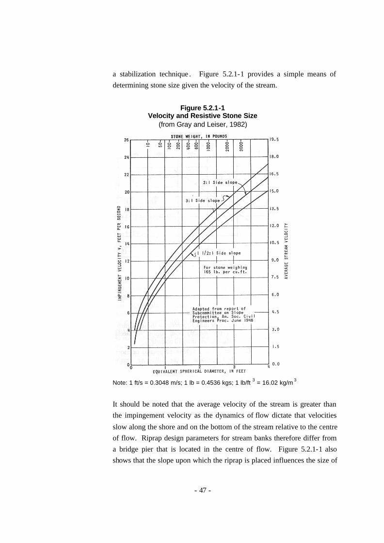
recognized expert in this field . The following materials are no substitute for good professional advice. 2.1 Riprap
Riprap constructed of competent rock is the most common traditional material
used for erosion protection (Transportation Association of Canada, 2001). There is a wide assortment of design guides for the design of riprap protection (e.g. Schiereck, 2001; Washington State Aquatic Habitat Guidelines Program, 2002; Veri-Tech Inc. 1998). One of the key questions in the design of riprap is the size
of the rock to use (Transportation Association of Canada, 2001). The Transportation Association of Canada (2001) identifies three methods of determining the size of rock to use in riprap projects.
1. Local experience. Work on the same stream under similar conditions used rock of a certain size and this has worked in the past.
- 4 -
2. Empirical guidelines. Standards are often developed by local authorities that specify riprap sizes and specifications for use. The government of New Brunswick provides such standards at http://www.gnb.ca/0173/30/0173300008-e.asp
3. Hydraulic relationships. Numerous models, analytical and experimental studies have been developed to determine riprap sizes in relation to the local hydraulics. Details of these are well beyond the scope of this document.
In addition to size of rock to be used, riprap design often specifies the type of rock to use as well as the configuration of the rock. Solid, durable rock that weathers very slowly is often specified. Igneous rock types high in silica such as granite often fit these criteria. The rock should also be more or less equi-dimensional.
That is, it should about the same size in all directions. The specifications may require that the rock be sorted or that quarry run rock can be used depending on the application (Transportation Association of Canada, 2001). In addition, it is important to consider the source of the rock relative to metal leaching and/or
introduction of sediment. A well designed riprap slope can provide erosion protection for many years. However, riprap failures can occur where the stream out- flanks the riprap leaving
the stone stranded as the stream erodes in another direction. In addition, riprap surfaces may cause the water to accelerate causing downstream erosion problems. In particular, where the natural banks of the stream are composed of fine textured surficial materials, introduction of rock may cause erosion in adjacent areas
(Schiereck, 2001). Large riprap can provide some habitat for small fish (Alberta Infrastructure, 1999). Boulder clusters can be used to provide habitat for a variety fish species
(Slaney and Zaldokas, eds. 1997). However, most riprap slopes do not support riparian vegetation and therefore lacks many of the elements that make functional fish habitat (large woody debris, shade, litter and insect fall, etc.). Suggestions for the incorporation of vegetation in riprap slopes are provided in section 4 of this
report.
- 5 -
2.2 Cast Concrete Systems
There are a wide variety of concrete based systems for control of erosion. Cast in
place systems such as concrete retaining walls and concrete channels are used in urban areas where absolute control of erosion is required. Such systems are not included in this review. Fabric-formed cast- in-place concrete revetments come in a variety of shapes and sizes (www.fabriform1.com) and are carried by a number
of different contracting companies (www.elish.com and www.samcal.com). These systems consist of a woven fabric that acts as forms for concrete that is pumped into the forms. By manipulating the stitching, the resulting structures can be formed as individual articulating blocks (with rope or cable between them) or
as a billowy concrete slab or as a slab with filter fabric closed holes that allow seepage to escape. Photographs of these systems show biologically inert, although erosion resistant, channels. Design specifications, including costs, could be obtained from distributors if one was interested in purchasing one of these
systems. Cast concrete blocks of varying shapes and sizes are used for erosion control (www.specblockusa.com/armortec). Articulated concrete mats are constructed of
interlocking blocks held together with stainless steel (or other materials on request) cables (“Armorflex”). These can be used to control erosion and can be revegetated (see Section 4). Photographs 2.2-1 and 2 show the application of articulated concrete mats to control erosion above a high pressure gas pipeline.
Loose blocks such as “Tri- lock” systems can be used to control erosion in a variety of settings (http://www.cci-industries.com/Pages/Tri-Lock.html). These systems can withstand flow velocities of up to 6 m/s and can be readily revegetated (http://www.grasscrete.com/pages/paving/trilock.htm), although the
size of revegetation material is limited to the size of the openings between the blocks. Also, should trees take root in a streambank where a “Tri- lock” system was being used, if the tree was ever to uproot and fall over, the integrity of the erosion resistance would be lost. There are a variety of different shapes that have
been developed for these blocks (http://www.hydropave.com/ and http://www.cci-industries.com/Pages/Tri-Lock.html), including large “jack” shaped blocks called “A-Jacks” that are used in very high energy situations such as high velocity flows or ocean waves (www.specblockusa.com/armortec).
- 6 -
Photograph 2.2-1. Articulating concrete mats (red arrow) are used here to protect the
underlying pipeline against erosion. Live cuttings (soaking in stream) are being installed in the holes in the mats.
Photograph 2.2-2. The same site shown in Photograph 2.2-1 is seen here during high
flows. The concrete mat (as well as the live gravel bar staking) was effective in holding the bank in place and protecting the newly planted cuttings from erosion.
- 7 -
2.3 Sheet Piling
Sheet piles consist of steel plates that are driven into the substrate and then locked
together to form a wall. Generally they are bent or curved to provide strength and have coupling systems that allow the panels to be joined together (http://www.tosakikai.co.jp/inquiry/TSM_TXT/chap_1.pdf). Sheet piling is also being made of plastic (http://www.materialsintl.com/engineering/budget.htm)
which is particularly useful in situations involving sea shores. Sheet piling is rarely used on small streams or rivers except where bridges are being constructed and sheet piles are used in a temporary manner to isolate the
work area. However, vinyl sheet piling that can be installed using a high pressure (http://www.cmilc.com/index.htm) water jet may be a useful solution for erosion along lakeshores or slow moving streams and rivers where there are no stones.
Establishing vegetation on sheet pile faces would be impossible without creating holes in the sheet piles. Although this may be feasible, there was no indication of such in the literature.
Soil bioengineering is the use of living plant materials to perform some engineering function (Polster, 1997). Soil bioengineering has been used for many centuries. Early Chinese records document the use of soil bioengineering for dyke repair in 28 BC
(http://www.wsdot.wa.gov/eesc/cae/design/roadside/SBwebsite/mainpage/BackgroundInfo/background.html). Records of the use of willows for stabilizing canal banks in the Netherlands and France date back to the Middle Ages (Donat, 1995). In the past 50 years the use of soil bioengineering has expanded in both Europe and North America (Lewis,
2000). Soil bioengineering treatments for streambank stabilization offer many advantages over the traditional engineering solutions discussed above. Donat (1995) lists four major
advantages:
- 8 -
1. Technical advantages including surface erosion protection; root reinforcement of the soil; soil drainage; and, protection from falling rock associated with the growth of the plants.
2. Ecological advantages such as the provision of habitat for other plants and animals living in or near the water body; improved soil conditions due to plant growth; and better moisture management from raindrop inception to evapotranspiration and water storage.
3. Economic advantages due to reduced construction and maintenance costs and the employment of semi-skilled workers.
4. Aesthetic advantages associated with the use of natural materials in natural settings.
Lewis (2000) notes that soil bioengineering projects typically require less heavy equipment than standard engineering treatments and are therefore less costly and create
less of an impact. In addition, hand crews can often walk into sites that are inaccessible by machine and can treat sites while they are small. The use of locally available plant materials that are genetically adapted to the area in which they are being used serves to keep costs down and ensure genetic integrity (Lewis, 2000). Soil bioengineering systems
strengthen as the living plant materials that are used in the structures take root and grow (Polster, 2001). Soil bioengineering treatments also provide the pioneering plant materials that will help to initiate natural succession on the disturbed sites (Polster, 1989). Natural successional processes are key to the maintenance of vegetation on the disturbed
site in perpetuity (Walker and del Moral, 2003). In many cases streambank erosion is associated with the loss of riparian cover. Utilization of soil bioengineering techniques to provide the stabilization of the
streambank restores the pioneering riparian species. This promotes the re-establishment of the natural successional processes that will eventually lead to a healthy riparian vegetation cover (Polster, 1991). Healthy riparian ecosystems are essential for healthy aquatic life. Riparian vegetation provide thermal regulation of streams; a feature that is
essential for the survival of some fish species. The roots and stems of riparian plants serve to secure the streambanks allowing development of overhanging banks as well as protecting against flood flow erosion by slowing water velocities adjacent to the banks. Riparian vegetation provides food and habitat for a variety of organisms including semi-
aquatic mammals (beaver, otter, mink, etc.), birds (Dippers) and invertebrates (many aquatic larval forms need riparian vegetation to complete their life cycle ). By providing appropriate riparian plants, soil bioengineering systems enhance the aquatic system.
- 9 -
Soil bioengineering treatments, with one exception (see live pole drains), are designed to treat surface disturbances and will not be effective where the origins of the instabilities
are deep seated. Surface erosion and shallow surface sloughing can be effectively treated with soil bioengineering methods. Soil bioengineering can also be used to control bank erosion as long as the erosion is resulting from high flows and most of the time the area that is actively being eroded is above the water line. The plants used in soil
bioengineering will not grow underwater. The following sections describe a range of soil bioengineering treatments. References and sources of information are cited for each system described. In many cases, a number
of authors have described the same soil bioengineering treatment. These cases are noted. Brief descriptions are provided in the following text. Details about the soil bioengineering treatment can be found in the references cited. The treatments are organized to present treatments designed for similar problems together so for instance,
treatments designed to address over-steepened slopes are grouped together while those designed for treatment of soil moisture problems are grouped together. Treatments developed to stabilize eroding streambanks are presented separately.
3.1 Soil Bioengineering for Eroding Streambanks
The following treatments are used to treat eroding streambanks. The first step in determining which treatment to use is to determine the cause of the erosion and
which soil bioengineering treatment (if any) will be effective in slowing or stopping the erosion. For instance, an eroding streambank may also be oversteepened so the treatment must deal with the erosio n issue as well as the oversteepened slope above. The following treatments are arranged from the
waterline up the streambank. 3.1.1 Brush Mattresses
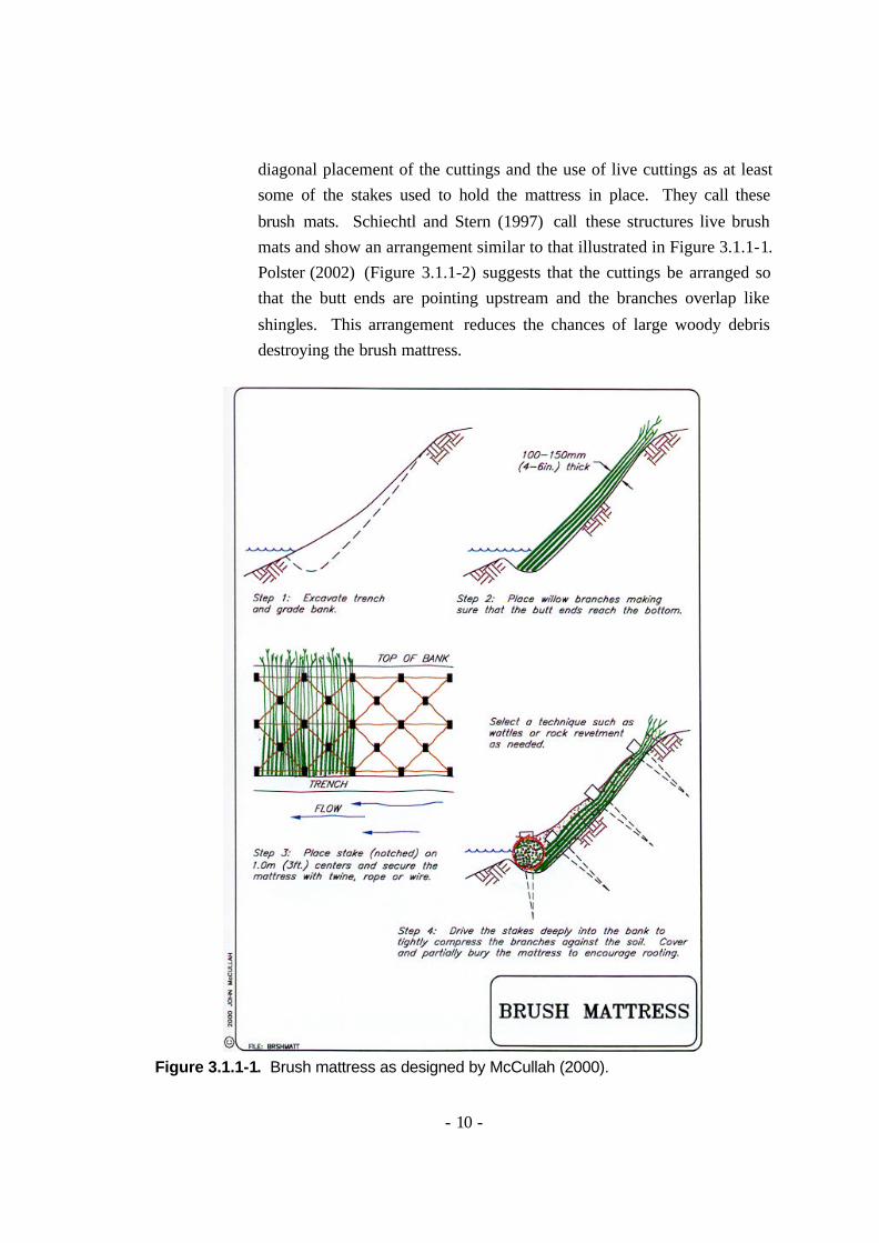
Brush mattresses consist of living cuttings (full cuttings without branch tips less than 0.75 cm) laid perpendicular to the stream with the butt ends
in a shallow trench at the toe of the slope. The cuttings are then tightly secured to the streambank with wire or twine. Figure 3.1.1-1 from John McCullah’s Bio Draw 1.0 (McCullah, 2000) shows one method of constructing brush mattresses. Muhlberg and Moore (1998) show a
- 10 -
diagonal placement of the cuttings and the use of live cuttings as at least some of the stakes used to hold the mattress in place. They call these
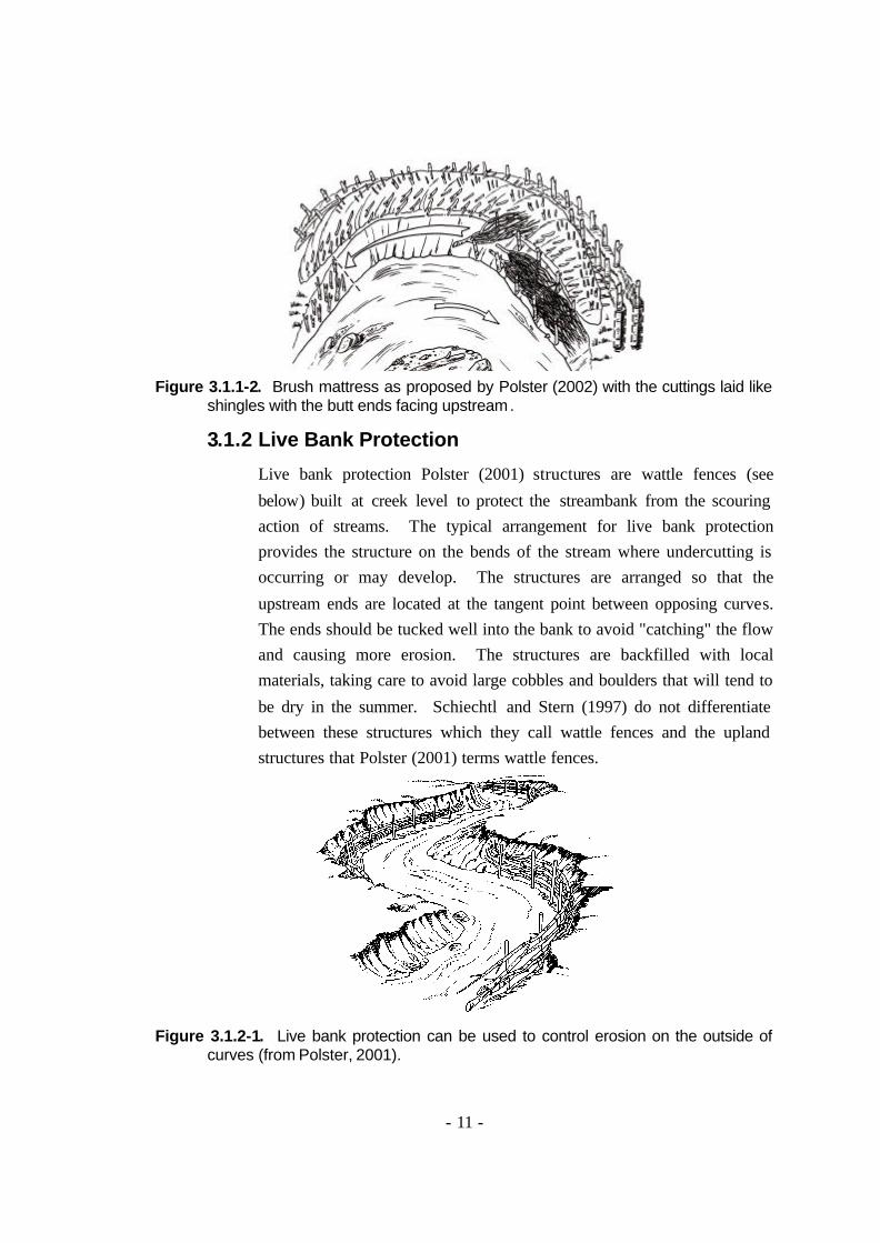
brush mats. Schiechtl and Stern (1997) call these structures live brush mats and show an arrangement similar to that illustrated in Figure 3.1.1-1. Polster (2002) (Figure 3.1.1-2) suggests that the cuttings be arranged so that the butt ends are pointing upstream and the branches overlap like
shingles. This arrangement reduces the chances of large woody debris destroying the brush mattress.
Figure 3.1.1-1. Brush mattress as designed by McCullah (2000).
- 11 -
Figure 3.1.1-2. Brush mattress as proposed by Polster (2002) with the cuttings laid like
shingles with the butt ends facing upstream.
3.1.2 Live Bank Protection
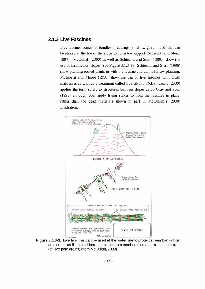
Live bank protection Polster (2001) structures are wattle fences (see
below) built at creek level to protect the streambank from the scouring action of streams. The typical arrangement for live bank protection provides the structure on the bends of the stream where undercutting is occurring or may develop. The structures are arranged so that the
upstream ends are located at the tangent point between opposing curves. The ends should be tucked well into the bank to avoid "catching" the flow and causing more erosion. The structures are backfilled with local materials, taking care to avoid large cobbles and boulders that will tend to
be dry in the summer. Schiechtl and Stern (1997) do not differentiate between these structures which they call wattle fences and the upland structures that Polster (2001) terms wattle fences.
Figure 3.1.2-1. Live bank protection can be used to control erosion on the outside of
curves (from Polster, 2001).
- 12 -
3.1.3 Live Fascines
Live fascines consist of bundles of cuttings (small twigs removed) that can be staked at the toe of the slope to form toe support (Schiechtl and Stern,
1997). McCullah (2000) as well as Schiechtl and Stern (1996) show the use of fascines on slopes (see Figure 3.1.3-1). Schiechtl and Stern (1996) show planting rooted plants in with the fascine and call it furrow planting. Muhlberg and Moore (1998) show the use of live fascines with brush
mattresses as well as a treatment called live siltation (cf.). Lewis (2000) applies the term solely to structures built on slopes as do Gray and Sotir (1996) although both apply living stakes to hold the fascines in place rather than the dead materials shown in part in McCullah’s (2000)
illustration.
Figure 3.1.3-1. Live fascines can be used at the water line to protect streambanks from
erosion or, as illustrated here, on slopes to control erosion and excess moisture (cf. live pole drains) (from McCullah, 2000).
- 13 -
3.1.4 Live Siltation
Live siltation consists living cuttings (with tips trimmed) inserted into a
trench that is excavated at the normal high water level. Large numbers of cuttings are used in the trench to create a very bushy shoreline at the high water level. Figure 3.1.4-1 shows two illustrations of live siltation.
Figure 3.1.4-1. Live siltation as illustrated Muhlberg and Moore (1998) (left) and by McCullah (2000) (right).
Coir logs or fascines can be used in the trench to add to the growth (in the case of fascines) and silt collection. Because the plants used in live siltation (and other soil bioengineering systems) can be substantially buried with silt and continue to grow and because these plants thrive on
the pounding associated with growing on streambanks, live siltation is an excellent technique for treatment of the toe of the slope on eroding streambanks.
- 14 -
3.1.5 Brush Layers
Brush layers (Figure 3.1.5-1) are horizontal rows of cuttings buried either in a fill or cut slope. Brush layers in fills are particularly useful where
eroded banks need to be rebuilt and the fill materials must be placed on steep (1.5 : 1 or greater) angles due to the geometry of the site. In these cases, cuttings (1.5 to 3 or 4 m long) can be inserted into the fills as they are constructed and can assist in creating a cohesive mass from the fill
material. The cuttings act to increase the shear resistance and therefore reduce the possibility of rotational or translational failures. As the living cuttings sprout and take root, this strength increases (Polster, 2001).
On undisturbed streambanks, brush layers are constructed by digging a trench across the slope and laying in the cuttings. These are built from the bottom of the slope so that the second trench excavation can be used to backfill the first and so on up the slope. Brush layers in in-situ materials
create rows of vegetation across the slope and can be used to establish riparian vegetation on steep streambanks. Lewis (2000) and many others (e.g. Schiechtl and Stern 1996; Gray and Sotir, 1996; Gray and Leiser, 1982; Howell, 1999) suggest the use of brush laye rs for treatment of steep
slopes. Brush layers in which rooted live plants are included are called hedge brush layers (Schiechtl and Stern 1996). Hedge brush layers provide the advantage of establishing an already growing plant as well as increasing the diversity of the vegetation cover.
Figure 3.1.5-1. Brush layers can be used on an in-situ slope (above left) or a fill slope (above right). When used in a fill, full-length cuttings can be used and can act as soil reinforcement (from Polster, 2001).
- 15 -
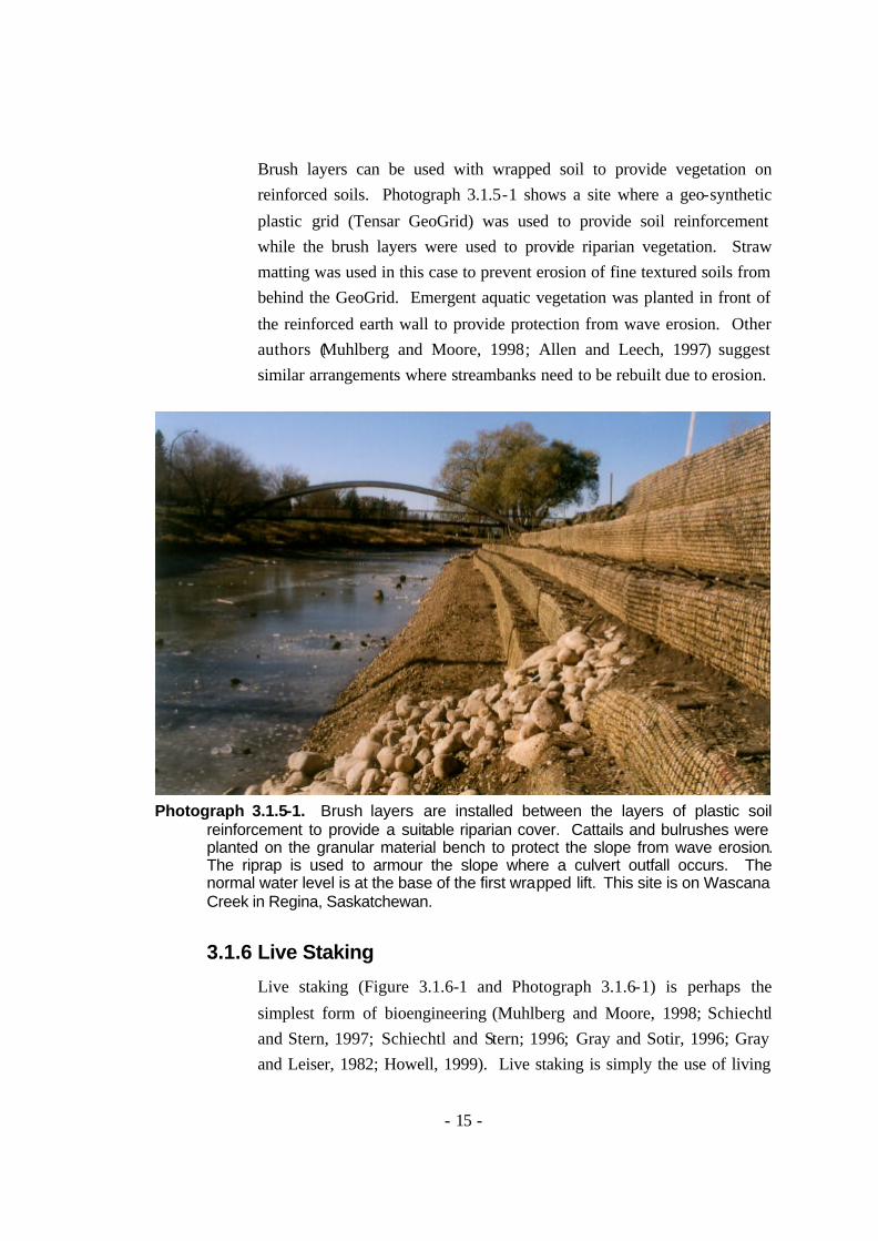
Brush layers can be used with wrapped soil to provide vegetation on reinforced soils. Photograph 3.1.5-1 shows a site where a geo-synthetic
plastic grid (Tensar GeoGrid) was used to provide soil reinforcement while the brush layers were used to provide riparian vegetation. Straw matting was used in this case to prevent erosion of fine textured soils from behind the GeoGrid. Emergent aquatic vegetation was planted in front of
the reinforced earth wall to provide protection from wave erosion. Other authors (Muhlberg and Moore, 1998; Allen and Leech, 1997) suggest similar arrangements where streambanks need to be rebuilt due to erosion.
Photograph 3.1.5-1. Brush layers are installed between the layers of plastic soil
reinforcement to provide a suitable riparian cover. Cattails and bulrushes were planted on the granular material bench to protect the slope from wave erosion. The riprap is used to armour the slope where a culvert outfall occurs. The normal water level is at the base of the first wrapped lift. This site is on Wascana Creek in Regina, Saskatchewan.
3.1.6 Live Staking
Live staking (Figure 3.1.6-1 and Photograph 3.1.6-1) is perhaps the
simplest form of bioengineering (Muhlberg and Moore, 1998; Schiechtl and Stern, 1997; Schiechtl and Stern; 1996; Gray and Sotir, 1996; Gray and Leiser, 1982; Howell, 1999). Live staking is simply the use of living
- 16 -
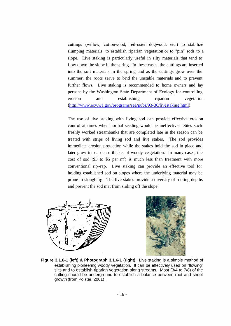
cuttings (willow, cottonwood, red-osier dogwood, etc.) to stabilize slumping materials, to establish riparian vegetation or to "pin" sods to a
slope. Live staking is particularly useful in silty materials that tend to flow down the slope in the spring. In these cases, the cuttings are inserted into the soft materials in the spring and as the cuttings grow over the summer, the roots serve to bind the unstable materials and to prevent
further flows. Live staking is recommended to home owners and lay persons by the Washington State Department of Ecology for controlling erosion and establishing riparian vegetation (http://www.ecy.wa.gov/programs/sea/pubs/93-30/livestaking.html).
The use of live staking with living sod can provide effective erosion control at times when normal seeding would be ineffective. Sites such freshly worked streambanks that are completed late in the season can be
treated with strips of living sod and live stakes. The sod provides immediate erosion protection while the stakes hold the sod in place and later grow into a dense thicket of woody ve getation. In many cases, the cost of sod ($3 to $5 per m2) is much less than treatment with more
conventional rip -rap. Live staking can provide an effective tool for holding established sod on slopes where the underlying material may be prone to sloughing. The live stakes provide a diversity of rooting depths and prevent the sod mat from sliding off the slope.
Figure 3.1.6-1 (left) & Photograph 3.1.6-1 (right). Live staking is a simple method of
establishing pioneering woody vegetation. It can be effectively used on "flowing" silts and to establish riparian vegetation along streams. Most (3/4 to 7/8) of the cutting should be underground to establish a balance between root and shoot growth (from Polster, 2001).
- 17 -
The cuttings used in live staking should be inserted into the soil so that at least 3/4 of the length of the cutting is underground. On drier sites, 7/8 of
the cutting should be inserted. Cuttings need not be planted vertically (as shown) but can be slipped into the soil diagonally, as long as the cutting will remain moist over most of its length. A dibble or a piece of rebar can be used to provide a pilot hole for the cuttings as long as the soil is packed
firmly around the cutting once the cutting is in the ground. Heavy gloves such as welder’s gloves can be used to push cuttings into the soil. Rubber auto body mallets can also be used to drive in cuttings. Where difficulty is encountered, cuttings may be trimmed to maintain the 3/4 or 7/8 burial, as
long as the cutting is at least 40 cm long.
3.1.7 Live Gravel Bar Staking
Excess gravel in many stream channels can sometimes be attributed to upslope land use practices and subsequent bank erosion. Natural
successional processes on these gravel bars eventually leads to the establishment of pioneering vegetation on the top of the bars. This slows the water flow across the bar, resulting in deposition of fines and further elevation of the bar surface. Prior to this deposition of fines,
establishment of vegetation by seed on the bar surface is limited due to harsh dry conditions during the summer. However, once the fines have accumulated species such as cottonwood and conifers can seed in. The key to starting this successional process is the initial establishment of the
pioneering species. Willows often serve this purpose naturally as they can sometimes establish under these harsh conditions. Live gravel bar staking (Figure 3.1.7-1 and Photograph 3.1.7-1) like
traditional live staking is a simple form of bioengineering. Live grave bar staking is the use of living cuttings to provide a pioneering vegetation cover on the tops of gravel bars that will help collect sediments as well as binding the gravel together with roots. Mitchell and Dyck (2000) suggest
the use of live staking on the gravel shores of reservoirs although they do not discuss the use of excavators for planting (http://www.sdafs.org/meetings/00sdafs/habitat/mitch1.htm). Live gravel bar staking is useful where excess gravel is causing stream instability. It
- 18 -
can be used in conjunction with live bank protection (see above) to provide a pioneering cover on streams where human activities have
disturbed normal alluvial processes. In these cases, cuttings up to 1.5 m long are inserted into the gravel in the dormant season, preferably the early spring, and as the cuttings grow over the summer, the roots serve to bind the gravel materials and reduce erosion during periods of high flows.
The cuttings used in live gravel bar staking should be inserted into the gravel so that at least three-quarters of the length of the cutting is underground. On higher bars and therefore drier sites, seven-eighths of
the cutting should be inserted. Cuttings should be slipped into the grave diagonally with the tips pointing downstream. It is important that the cuttings remain moist over most of their length. Cuttings should be planted with the distal (top) end up. It may be useful to leave short stubs
of branches on the cutting (as shown) so that the top of the cutting will be known when the cutting is planted. The spacing between cuttings will vary depending on the materials, but can be as little as 10 cm. In most cases it may be useful to use a small excavator to dig holes for the cuttings
to be planted in as inserting cuttings into gravel bars is very difficult. Where an excavator is used, 4 or 5 cuttings can be planted in a clump using one bucket hole. This will recreate the clumps of vegetation seen on bars where natural processes have established willows.
The cuttings used in gravel bar staking should be collected from willows, red-osier dogwood or cottonwood growing in similar conditions. Species such as Smooth Willow (Salix glauca) that are commonly found on gravel
bars are ideal for use in gravel bar staking. Sandbar willows (Salix exigua and S. sessilifolia) are reported as being effective stabilizers of sand and gravel bars due to their ability to spread from creep ing rhizomes (Brayshaw, 1996). The cuttings must be inserted well down in the gravel
as the upper surface of most gravel bars dries considerably during the summer. In Alberta situations where high flows correspond to spring freshet, it is best to conduct live gravel bar staking in the fall or early spring with the expectation that the plants will have to survive the first
high water without having rooted. Work in streams such as live gravel bar
- 19 -
staking will be subject to permission from fisheries agencies. Such permission must be obtained prior to conducting such work.
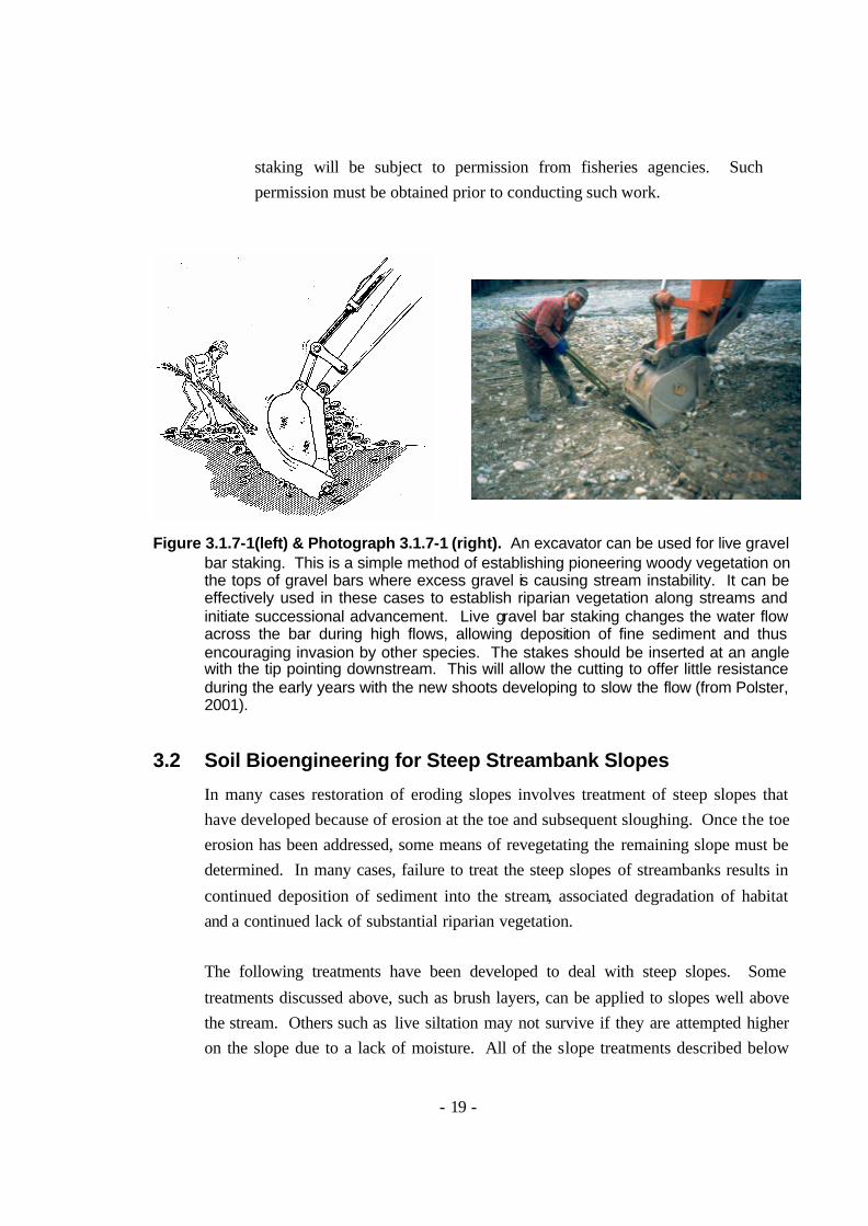
Figure 3.1.7-1(left) & Photograph 3.1.7-1 (right). An excavator can be used for live gravel
bar staking. This is a simple method of establishing pioneering woody vegetation on the tops of gravel bars where excess gravel is causing stream instability. It can be effectively used in these cases to establish riparian vegetation along streams and initiate successional advancement. Live gravel bar staking changes the water flow across the bar during high flows, allowing deposition of fine sediment and thus encouraging invasion by other species. The stakes should be inserted at an angle with the tip pointing downstream. This will allow the cutting to offer little resistance during the early years with the new shoots developing to slow the flow (from Polster, 2001).
3.2 Soil Bioengineering for Steep Streambank Slopes
In many cases restoration of eroding slopes involves treatment of steep slopes that have developed because of erosion at the toe and subsequent sloughing. Once the toe erosion has been addressed, some means of revegetating the remaining slope must be determined. In many cases, failure to treat the steep slopes of streambanks results in
continued deposition of sediment into the stream, associated degradation of habitat and a continued lack of substantial riparian vegetation. The following treatments have been developed to deal with steep slopes. Some
treatments discussed above, such as brush layers, can be applied to slopes well above the stream. Others such as live siltation may not survive if they are attempted higher on the slope due to a lack of moisture. All of the slope treatments described below
- 20 -
tend to provide horizontal structures or plant growth across the slope to arrest the movement of materials down the slope. The vegetation limiting feature of steep
slopes is the movement of materials down the slope, either because plants can not become established on a moving substrate or because the materials damage or bury the plants below. The old adage ‘A rolling stone gathers no moss’ applies equally to vegetation on slopes.
3.2.1 Wattle Fences
Wattle fences (Figure 3.2.1-1) are short retaining walls built of living cuttings (Polster, 2001). Lewis (2000) calls these structures willow fences to differentiate them from the term wattle that is sometimes applied to a willow
bundle described above as a fascine. Gray and Sotir (1996) equate the term willow wattling to live fascines. Wattle fences described by Polster (2001) take up the vertical component of the slope, reducing the effective slope angle and allowing vegetation to become established. They create a step in the
slope. In addition, the living cuttings used to make the walls sprout and grow, thus further strengthening the structure. Wattle fences are used where site moisture conditions will allow the living cuttings on the face of the fence to sprout and grow. Sites where fine textured soils can provide ample summer
moisture or where seepage of groundwater provides moisture are suitable for wattle fence installations. Wattle fences provide breaks in the slope and can therefore reduce the impact
of rolling materials on vegetation growing lower on the slopes. In many cases, vegetation will have difficulty in becoming established where it is being constantly bombarded by materials from above. Wattle fences can protect vegetation growing lower on the slope and can assist in the revegetation of the
sites through protection from rolling rocks and sliding debris. Wattle fences are used to reduce the effective slope of oversteepened areas. They are most effective where moisture is plentiful and where the cuttings
used to construct the fences will not dry out. In this regard, backfilling the fences with fine texture materials will assist in providing moisture during dry summer periods. The first year of fence growth is the most critical as it is at this time that the cuttings may show significant amounts of shoot growth with
little supporting root growth. This causes summer desiccation. Wattle fences
- 21 -
provide rows of growing vegetation. Willows can continue to grow when buried and therefore provide a good plant material for wattle fences where
falling materials are expected to bury vegetation growing lower on the slopes.
Figure 3.2.1-1. Wattle fences are short retaining walls constructed of living cuttings. They
are used to provide slopes that will support plant growth where oversteepened slopes are preventing plant establishment. On steeper slopes, wattle fences are constructed closer together. Wattle fences have been successfully used on slopes that are as steep as 70 degrees. (from Polster, 2001).
Wattle fences can provide support for small (up to 30 cm deep) translational soil slumps or where excess soil moisture results in small (1 to 2 m deep) rotational failures of surface materials. In these cases, the wattle fences allow moisture to drain through the face of the fence while the soils are retained
behind the fence. Where slumps are particularly soupy, branches and twigs may be packed in behind the cuttings to provide additional support for the wet soils. Wattle fences can be used in combination with live pole drains (see below) to support the slumps while the live pole drains provide drainage of
the excess moisture. Wattle fences are cons tructed by establishing the supporting rebar or cuttings in a row in the ground and placing the cuttings behind these supports. Soil
materials are then backfilled behind the cuttings and additional cuttings are added to increase the height of the fence. Additional soil materials are backfilled behind these cuttings until the final height of the fence is reached. Resloping behind the fence should be conducted to create a slope of about 2 :
1 or less between the top of the fence and the bottom of the fence above. Wattle fences are constructed from the bottom of the slope up the slope so that
- 22 -
workers may have a place to stand while additional fences are constructed. Photographs 3.2.1-1 and -2 show the use of wattle fences to treat sea cliffs that
formed fo llowing shoreline erosion below. Stabilization of these slopes would not have been possible without previous treatment of the toe erosion at the beach level.
Schiechtl and Stern (1996) call structures that consist of cuttings that are woven through rows of stakes with the butt ends of each cutting buried in the ground then woven into the fence (Figure 3.1.2-2). Because of the lack of significant burial of the cuttings, few of the cuttings take root and grow.
Schiechtl and Stern (1996) suggest that if the structures are buried into the soil there is a greater chance of sprouting and growing.
Figure 3.2.1-2. Wattle fences as described by Schiechtl and Stern (1996).
3.2.2 Modified Brush Layers
Modified brush layers (Polster, 2001) are essentially a brush layer (Gray and Leiser, 1982; Schiechtl and Stern, 1996; Schiechtl and Stern 1997; Gray and Sotir, 1996) supported on a short, small log or board. The use of a log or
board for support of the brush layer provides the initial added advantage over tradit ional brush layers that the small terrace that is created can serve to "catch" rolling stones rather than allowing them to roll down the slope, gathering speed and damaging vegetation. Although the board or log will
eventually rot, the cuttings will by that time have grown to the point where they are stabilizing the slope.
- 23 -
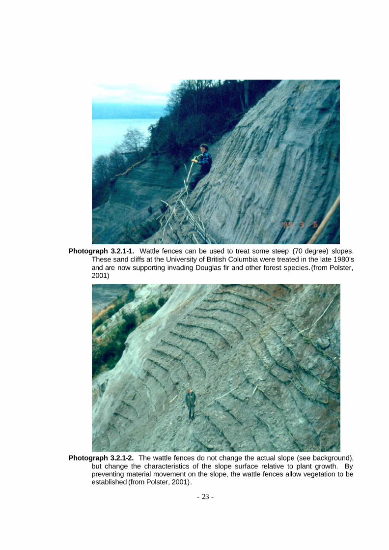
Photograph 3.2.1-1. Wattle fences can be used to treat some steep (70 degree) slopes.
These sand cliffs at the University of British Columbia were treated in the late 1980’s and are now supporting invading Douglas fir and other forest species. (from Polster, 2001)
Photograph 3.2.1-2. The wattle fences do not change the actual slope (see background),
but change the characteristics of the slope surface relative to plant growth. By preventing material movement on the slope, the wattle fences allow vegetation to be established (from Polster, 2001).
- 24 -
As the cuttings that are used in the brush layer grow, the wall of plants will also serve to trap rocks and soil and prevent movement of materials down the
slope, thus further protecting vegetation on the slopes. Modified brush layers can be used on sites that would be too dry for effective wattle fence growth but where some form of additional support is needed for stabilization of the slopes. Eroded gravel banks that form along some streams are candidates for
treatment with modified brush layers.
Figure 3.2.2-1. Modified brush layers should be staggered across the slope (left). Boards
or logs can be used for support. Three different positions for placement of cuttings are shown in the diagram on the right. On mesic sites, modified brush layers should be built with the cuttings above the board or log (“1”). On dry sites, the cuttings should go below the board or log (2), while on very moist sites a small wattle fence can be installed below the board or log (3) to provide drainage. Modified brush layers are perfect for ravelling gravel slopes (from Polster, 2001).
Logs or boards (5 cm by 20 cm (2” by 8”)) approximately 2 m in length are used for modified brush layers. This allows a large number of modified brush layers to be established on the slope rather than one or several long ones. This
has the advantage of providing separate, independent structures so that if a very large rock comes down and destroys one of the modified brush layers, there are still others to do the work. Many soil bioengineering systems use this "strength in numbers" concept.
- 25 -
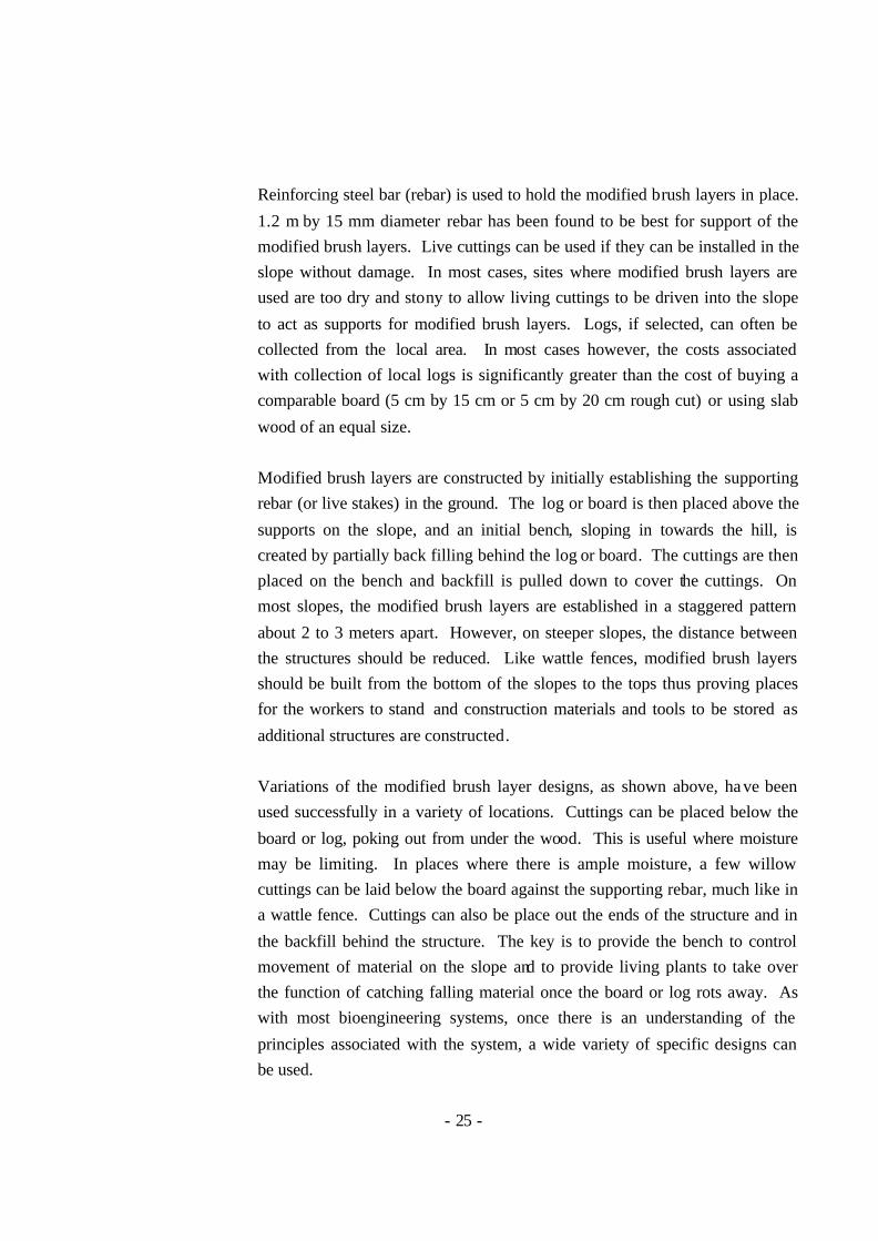
Reinforcing steel bar (rebar) is used to hold the modified brush layers in place.
1.2 m by 15 mm diameter rebar has been found to be best for support of the modified brush layers. Live cuttings can be used if they can be installed in the slope without damage. In most cases, sites where modified brush layers are used are too dry and stony to allow living cuttings to be driven into the slope
to act as supports for modified brush layers. Logs, if selected, can often be collected from the local area. In most cases however, the costs associated with collection of local logs is significantly greater than the cost of buying a comparable board (5 cm by 15 cm or 5 cm by 20 cm rough cut) or using slab
wood of an equal size. Modified brush layers are constructed by initially establishing the supporting rebar (or live stakes) in the ground. The log or board is then placed above the
supports on the slope, and an initial bench, sloping in towards the hill, is created by partially back filling behind the log or board. The cuttings are then placed on the bench and backfill is pulled down to cover the cuttings. On most slopes, the modified brush layers are established in a staggered pattern
about 2 to 3 meters apart. However, on steeper slopes, the distance between the structures should be reduced. Like wattle fences, modified brush layers should be built from the bottom of the slopes to the tops thus proving places for the workers to stand and construction materials and tools to be stored as
additional structures are constructed. Variations of the modified brush layer designs, as shown above, ha ve been used successfully in a variety of locations. Cuttings can be placed below the
board or log, poking out from under the wood. This is useful where moisture may be limiting. In places where there is ample moisture, a few willow cuttings can be laid below the board against the supporting rebar, much like in a wattle fence. Cuttings can also be place out the ends of the structure and in
the backfill behind the structure. The key is to provide the bench to control movement of material on the slope and to provide living plants to take over the function of catching falling material once the board or log rots away. As with most bioengineering systems, once there is an understanding of the
principles associated with the system, a wide variety of specific designs can be used.
- 26 -
3.2.3 Live Smiles
Flowing silty soils can create a significant surface instability problem. Treatment with brush layers, modified brush layers or wattle fences often fail
under these circumstances due to an inability to hold the flowing materials. In many cases, the weight of the flowing mud causes structures such as modified brush layers or wattle fences to collapse (toppling failure) while brush layers may be swept from the slope or may not control the flow of the mud and thus
do not solve the problem. Live smiles (Polster, 2001) make use of the tensile strength of the cuttings to support the mud and thus are significantly stronger than wattle fences or modified brush layers. Establishment of the cuttings in a bowed configuration (catenary curve) transfers the load from a toppling load
to one where the cuttings are under tension. Most plant materials are extremely strong under tension and thus the live smiles can hold far more mud than a traditional wattle fence or modified brush layer.
Live smiles (Figure 3.2.3-1 and Photographs 3.2.3-1 & 2) are porous and thus serve to drain the flowing silts, increasing the strength of the soil itself. Saturated silts have very little strength and thus flow easily. However, as these materials dry, they can develop significant strength and thus can stand at
much steeper slopes. In addition, the flowing silts tend to provide a good contact between the soil and the cuttings, thus allowing roots to develop readily. Live smiles can be an effective treatment for flowing silts as they help to drain the moisture causing the silts to flow and eventually developing
a strong root system in this otherwise weak material. Live smiles should be between 2 and 5 m wide depending on the nature of the slope and the size of the cuttings available. On steeper slopes or with thinner
cuttings, the smiles should be smaller while on flatter slopes or with larger cuttings the smiles can be wider. They can be up to 40 cm high in the middle, tapering at the ends as shown in the drawing. The rebar supporting the live smiles should be firmly established in the underlying in-situ material. Spacing
between rebar should be 50 to 60 cm to provide a firm foundation for the structure. The live smiles should be spaced in such a manner that there is no area on the slope where a significant amount of flowing mud can accumulate. As with most bioengineering systems, numerous live smiles will provide the
best results.
- 27 -
Figure 3.2.3-1 and Photographs 3.2.3-1 & 2. Live smiles can provide an effective
treatment for flowing silts. The catenary curve allows the cuttings to act in tension for increased strength while the porous face of the structures provides drainage. The cuttings should be tightly tied to the rebar at the tops while any required splices should be tightly joined.
3.2.4 Cordons
Schiechtl and Stern, (1996) present a technique called cordons (Figure 3.2.4-1) that comes from Praxl (no reference given). Lewis (2001) reports the use of cordons at a site in Washington State but does not specifically discuss the results obtained from the cordon use (one of many techniques used at this
site). Cordons are also mentioned in the B.C. Forest Practices Code Soil Rehabilitation Guidebook but no details of their use are given (http://www.for.gov.bc.ca/tasb/legsregs/fpc/FPCGUIDE/soilreha/rehabtoc.htm). The US EPA mentions cordons but again no details of use are given
(http://www.epa.gov/owow/nps/MMGI/Chapter3/ch3-2h.html). Cordons are mentioned at several other web sites but details of the applications in which they are or should be used, construction, or results are not given (http://www.dnrec.state.de.us/dnrec2000/Divisions/Soil/dcmp/mmforest.htm;
http://www.greenlaws.lsu.edu/erosion.htm; and http://www.deq.state.id.us/water/nps/2003Compendium_Part3.pdf). Donat (1995) also mentions cordons but does not describe them or show an illustration. This technique does not appear to be widely used.
- 28 -
Cordons are used on slopes and consist of two dead poles covered with conifer branches onto which live cuttings are placed. The whole structure is
covered with soil with only the cuttings sticking out. The cuttings form a system that is not unlike a brush layer and therefore has the same properties. Because the soil around the cuttings is loose, the cuttings have the potential to grow readily, although the inclusion of the conifer branches and the poles may
tend to dry out the soil around the roots of the cuttings. The dead wood and conifer branches will also use nitrogen as they decompose. No discernible advantages can be seen in this technique over normal brush layers. There is no terrace formed as in modified brush layers or wattle fences, and the added
dead material does not appear to increase the effectiveness of the structures. This technique could be considered a biotechnical treatment as it includes dead material, although, as mentioned, the dead materials do not appear to add to the stabilization. It has been included in this section as some soil
bioengineering systems use non- living materials.
Figure 3.2.4-1. Cordons as presented by Schiechtl and Stern, (1996).
- 29 -
3.2.5 Live Palisades
There are numerous sites where clearing to the banks of lakes, streams and rivers has eliminated the riparian vegetation and thus the bank holding root
systems. Replacement of suitably sized trees can take many decades. Live palisades (Polster, 2001) are designed to provide a wall of stout balsam poplar trees along eroding stream banks. The trees will develop a dense root network and resist erosion of the bank. Live palisades consist of a row of large
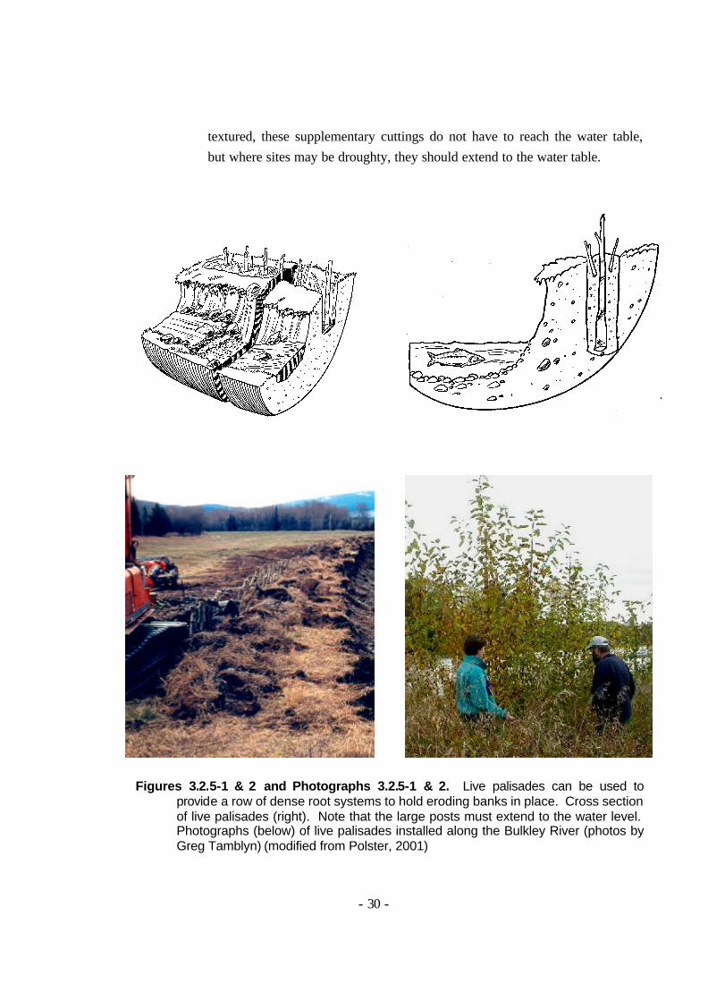
balsam poplar (cottonwood) cuttings established in a trench two or three meters from the eroding bank. Cuttings to be used for live palisades must be at least 4 cm in diameter at their tip. They should be at least 3 m long, with about 1 m left above the ground. The cuttings must be inserted down to the
water level so that the plants will have water. Live palisades can be constructed with additional cuttings (willow and red-osier dogwood) as shown. These additional cuttings will help to provide site diversity. Live palisades can be used on eroding farm fields or clear-cuts where loss of
riparian vegetation has resulted in severe erosion. The balsam poplar / cottonwood cuttings that are used in the construction of live palisades will provide shade as well as leaf litter for the stream. As the trees mature they will provide large woody debris that can act as interim habitat while later
successional conifers establish. Figures 3.2.5-1 and 2 show the typical design for live palisades while Photographs 3.2.5-1 and 2 show installation of cuttings along the Bulkley River in central B.C. as well as the growth of the cuttings three of years after installation.
A trench should be excavated to the water table 2 or 3 metres from the crest of the eroding slope. The full depth need not be excavated as the balsam poplar posts can be inserted into slits in the bottom of the trench created by the
excavator. Additional cuttings can be added to the open trench prior to backfilling. Watering may be needed if the depth to the water table is too great for reasonable excavation. Stout (up to 20 cm diameter) posts should be used as these will grow most rapidly. Live palisades are designed to provide a
strong riparian cover of balsam poplar (cottonwood) trees adjacent to eroding banks. Note that it is important to have the large balsam poplar cuttings extend down into the water table if possible so that these plants will have ample water. Willow and red-osier dogwood cuttings can be established in
the trench used for the balsam poplar posts. Where soils are reasonably fine
- 30 -
textured, these supplementary cuttings do not have to reach the water table, but where sites may be droughty, they should extend to the water table.
Figures 3.2.5-1 & 2 and Photographs 3.2.5-1 & 2. Live palisades can be used to provide a row of dense root systems to hold eroding banks in place. Cross section of live palisades (right). Note that the large posts must extend to the water level. Photographs (below) of live palisades installed along the Bulkley River (photos by Greg Tamblyn) (modified from Polster, 2001)
- 31 -
3.3 Soil Bioengineering for Water and Moisture Control
Seepage and minor gullies may enter lakes, stream and river systems carrying sediment that may harm fish and fish habitats. The following soil bioengineering systems have been developed to address seepage and to control erosion in minor, ephemeral streams.
3.3.1 Live Pole Drains
Live pole drains (Figure 3.3.1-1 and Photographs 3.3.1-1 through 4) are constructed of bundles of living cuttings and are used to provide stability to
sites where seepage creates excess soil moisture that results in soil instabilities. The bundles of cuttings are placed in shallow trenches in such a manner that they intersect and collect the moisture. The bundles are then lightly buried with local materials, taking care to avoid over-burial. Careful
trimming of the cuttings is not required if all pre-formed leaf buds are removed, although the bundles should be as tight as possible. The plants used to form the bundles sprout and grow, with the moisture continuing to drain from the lower end. Sites where excess soil moisture results in site instability
can be treated with live pole drains. Traditional engineering solutions often entail the installation of "French drains" or loading the face of the slope with rock. However, live pole drains can be used to drain excess moisture from the site and provide a cover of woody riparian vegetation. The growth from the
live pole drains forms the initial cover on the seepage site, allowing other species to invade. As with other bioengineering techniques, live pole drains must be designed to suit the specific conditions of the site. Schiechtl and Stern, (1996) call these fascine drains while Gray and Sotir (1996) call them
pole drains. A variety of different shapes can be used for the drains depending on the site conditions. A "Y" pattern (see drawing) of the drains can be used to collect
moisture from a diffuse seepage zone while a linear pattern can be used where a discrete seepage site exists. The objective in design of the drains is to collect all of the moisture and to get it to drain away as quickly as possible. The drains grow into a dense stand of hydrophytic vegetation, which is
exactly what nature would produce given enough time. Thus this technique
- 32 -
fits into the successional reclamation scheme far better than conventional "French" drains would. In addition, live pole drains can be installed without
machine access and at fraction of the cost of traditional hard engineering solutions. Seepage caused soil slumps such as those that occur along stream banks can be stabilized using live pole drains.
Live pole drains are constructed by excavating a shallow trench from the site of seepage down the slope and away from the problem area. A bundle of cuttings is placed in the trench and lightly backfilled with local materials. The bundle is composed of cuttings with tips and butts alternating. The bundle is
tied with bailing twine or mechanics wire as tightly as possible. Twigs and branches should be kept on the cuttings where possible as long as the leaf buds are removed. Sites that are particularly wet may require rocks to hold the bundles down in the trench (see Photograph 3.3.1-1. In these cases, it may
not be possible to actually excavate the trench, and the bundles can be inserted by standing on them and pushing them down into the mud. The key to live pole drain construction is to establish the drains in the area of seepage so that the drains provide a controlled alternative for the moisture to escape from the
bank.
Figure 3.3.1-1. Live pole drains can be used to stabilize slumping soils. This view shows
the layout of live pole drains in a slump with the covering soils removed for clarity. The section shows a typical covering (1 – 2 cm). Some twigs from the bundles should be left above ground.
- 33 -
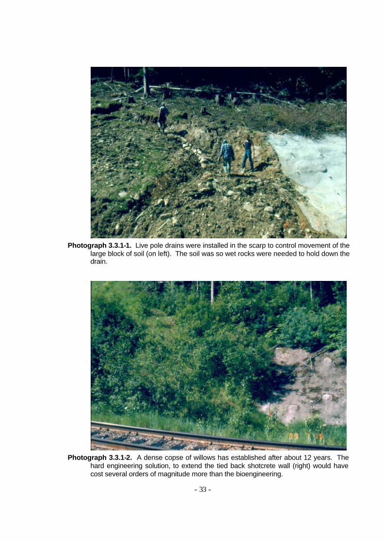
Photograph 3.3.1-1. Live pole drains were installed in the scarp to control movement of the
large block of soil (on left). The soil was so wet rocks were needed to hold down the drain.
Photograph 3.3.1-2. A dense copse of willows has established after about 12 years. The
hard engineering solution, to extend the tied back shotcrete wall (right) would have cost several orders of magnitude more than the bioengineering.
- 34 -
Photograph 3.3.1-3. Live pole drains provide immediate drainage of “soupy” soils. Bundles
of willow are inserted and act as a preferred flow path for subsurface flows, moving the water through sensitive soils.
Photograph 3.3.1-4. The live pole drain continues to drain water for years after
establishment. As the system matures, the site develops into a seepage area in a forest. The clump of willows to the right of the people has grown from the bundles shown in the picture above.
- 35 -
3.3.2 Live Gully Breaks
Live gully breaks (Figure 3.3.2-1 and 2 and Photograph 3.3.2-1) are large wattle fences built in gullies to control the flow of water down the gully. Live
gully breaks can be helpful in the revegetation and stabilization of gullies that are actively eroding by providing sites where materials may be trapped and where vegetation can become established. As with any bioengineering system, live gully breaks will strengthen with age. Schiechtl and Stern,
(1997) use fascine bundles to create steps in gullies and thus control erosion. Spacing of live gully breaks depends on the steepness of the channel but ranges from 5 to 10 m between the structures. Rebar stakes or live stakes are
driven into the gully to form a crescent on the contour, with the outer ends slightly higher than the stakes near the centreline of the gully. Cuttings are then established behind the stakes. For narrow gullies, the cuttings may need to butt into the opposite side wall, forming an overlapping lattice while on
wider gullies, the cuttings may be bent around the inside of the gully. The centre of the live gully break should be lower than the wings to prevent water from flowing out along the wings and creating a problem. The gully breaks may be backfilled with local materials. In some cases, it is useful to provide a
rock drain in the centre of the gully break to allow water to flow through, although care must be taken to provide fine textured materials for most of the backfilling. Backfilling should create a small terrace in the gully that will trap eroding materials.
Live gully breaks will act to trap materials that would otherwise flow down into the streams and rivers. The physical structure of the live gully breaks serves this purpose initially while the growth of the cuttings and the
establishment of rows of willows will provide long term control of erosion. Willows will continue to grow even when deeply buried and will reinforce the soil through the growth of roots. Roots from the willows used in the live gully breaks will provide substantial reinforcement of the soils. Root tensile
strengths of birch (expected to be similar to willow) have been measured to be 464 kg/cm2 for root sizes less than 2 mm (Gray and Leiser, 1982), while spruce - hemlock roots were found to have a strength of 102 kg/cm2 for root sizes less than 2 mm (Gray and Leiser, 1982). Coastal Douglas fir roots were
found to have a tensile strength of 578 kg/cm2 for root sizes less than 2 mm
- 36 -
(Gray and Leiser, 1982). Once established, the plants used to form the live gully breaks will serve to control erosion and minor debris flows.
Figure 3.3.2-1 & 2 and Photograph 3.3.2-1. Live gully breaks act to slow the velocity of
water movement down a gully and thus to control erosion and trap sediments. In narrow gullies (above right) the cuttings are crossed at the back of the gully with the tips higher than the centre (backfill removed for clarity) while in wider gullies (below right and photo) the structure is more like a “U” shaped wattle fence (from Polster, 2001).
3.3.3 Branch Packing
Schiechtl and Stern, (1997) describe branch packing as a technique for
treating eroded gullies (Figures 3.3.3-1 and 2). The treatment is not unlike a brush mattress (described above) in that it is the mass of vegetation that serves to control erosion and to trap sediment. As the living cuttings sprout and grow, the gully becomes plugged with a dense cover of woody vegetation,
preventing future erosion but allowing water to continue to flow. Gray and Sotir (1996) describe a system for use on deep gullies and slumps that uses
- 37 -
wooden stakes to hold the cuttings in place while the gully is refilled. This system is similar to brush layers in a fill except with wooden stakes.
Figures 3.3.3-1 (left) & -2 (right). Branch packing according to Schiechtl and Stern, (1997) on the left is constructed without filling the gully while Gray and Sotir (1996) show a treatment where stakes made of dead material (could use live) are used and the gully is filled (from Schiechtl and Stern, (1997) and Gray and Sotir (1996) respectively)
3.3.4 Live Silt Fences
Live silt fences (Polster, 2001) (Figure 3.3.4-1 and Photograph 3.3.4-1) are used to reduce sediment movement on low gradient ephemeral streams.
Where live gully breaks can be used on very steep gullies and seasonal streams, and live bank protection can be used on larger streams and rivers, live silt fences are used on smaller intermittent streams with lower gradients. Live silt fences are simply rows of cutt ings stuck into the stream bed to slow
water velocities and cause sediments to be deposited. The rows of cuttings also serve to trap floating debris that further slows water velocities. Once the cuttings grow, the water flows between the stems of the growing cuttings,
- 38 -
creating a brushy, swampy area characteristic of natural seepage areas and small streams.
Figure 3.3.4-1 and Photograph 3.3.4-1. Live silt fences can be used to provide a willow coppice in smaller, slow moving streams and ditches. They act by slowing the velocity of the water and allowing sediments to settle out. The cuttings can be either in single rows (as shown) or multiple rows in each band (as shown in the photo above). Note the use of live bank protection on the right bank (from Polster, 2001).
Willow, red-osier dogwood and cottonwood cuttings are particularly useful for live silt fences as these species will continue to grow when their stems are
buried. Live silt fences can be established in swales and small drainage ditches that may be depositing sediment into lakes streams and rivers. These will assist in restoring the sites so that rather than continuing to erode, these small channels can act as sediment traps and provide clean water to
downstream sites. The natural filtering ability of deciduous brush land can be recreated using live silt fences on the small drainages and seepages from the landslides and torrented gullies. Schiechtl and Stern, (1997) use the term palisade to refer to a very similar structure (Figure 3.3.4-2).
Figure 3.3.4-2. Palisades as described by Schiechtl and Stern, (1997) are similar to live silt
fences as described by Polster (2001) (from Schiechtl and Stern, 1997)
- 39 -
3.3.5 Non-Woody Soil Bioengineering Systems
Many non-woody species play an important role in protecting streambanks and lake shores from erosion. Muhlberg and Moore (1998) describe the use of
transplanting sprigs for establishment of grasses and sedges. Photographs 3.3.5-1 and 3.3.5-2 show the use of cattails and bulrushes to protect a creek bank from wave and streambank erosion in Regina, Saskatchewan.
Non-woody plant materials are most commonly used where these naturally form the dominant stabilizing element along a shoreline (Muhlberg and Moore, 1998). Sod plugs can be easily transplanted onto sites where gentle flows or wave erosion might otherwise cause loss of bank materials (Schiechtl
and Stern, 1997). Selection of species that spread readily by creeping rhizomes will help to ensure the planted vegetation establishes sufficient density to perform the desired protection.
Photographs 3.3.5-1 & 2. Sprigs of emergent aquatic vegetation such as Cattails
(Typha latifolia) and bulrushes (Schoenoplectus spp.) can be used to provide erosion protection from relatively slow moving prairie streams and from waves. Planting undertaken in the spring has grown over the summer to fully protect the shore from wave and streambank erosion. Photos take on Wascana Creek in Regina, Saskatchewan.
Biotechnical slope stabilization and erosion control treatments use a combination of living
materials and non-living structural elements. These treatments have been more widely used in North America (Gray and Leiser, 1982) than in Europe where soil bioengineering treatments are more widely used (Schiechtl and Stern, 1996 and 1997), although there are numerous examples of the use of both systems. As with soil bioengineering systems,
biotechnical solutions use living plant materials and in order for the plants to grow as designed they must be treated with care. Details of the collection and handling of willow, red-osier dogwood and cottonwood cuttings may be found in Crowder (1995) (http://plant-materials.nrcs.usda.gov/pubs/wapmctn290195.pdf).
4.1 Biotechnical Treatments for Bank Stabilization
Many of the standard engineering treatments for dealing with bank erosion have been adapted by the installation of plant materials. In some cases, the plants form an important part of the stabilization, such as vegetated wooden crib walls where the
wooden members will eventually rot away but the vegetation will just keep getting stronger and stronger. The following techniques are some of the more common treatments.
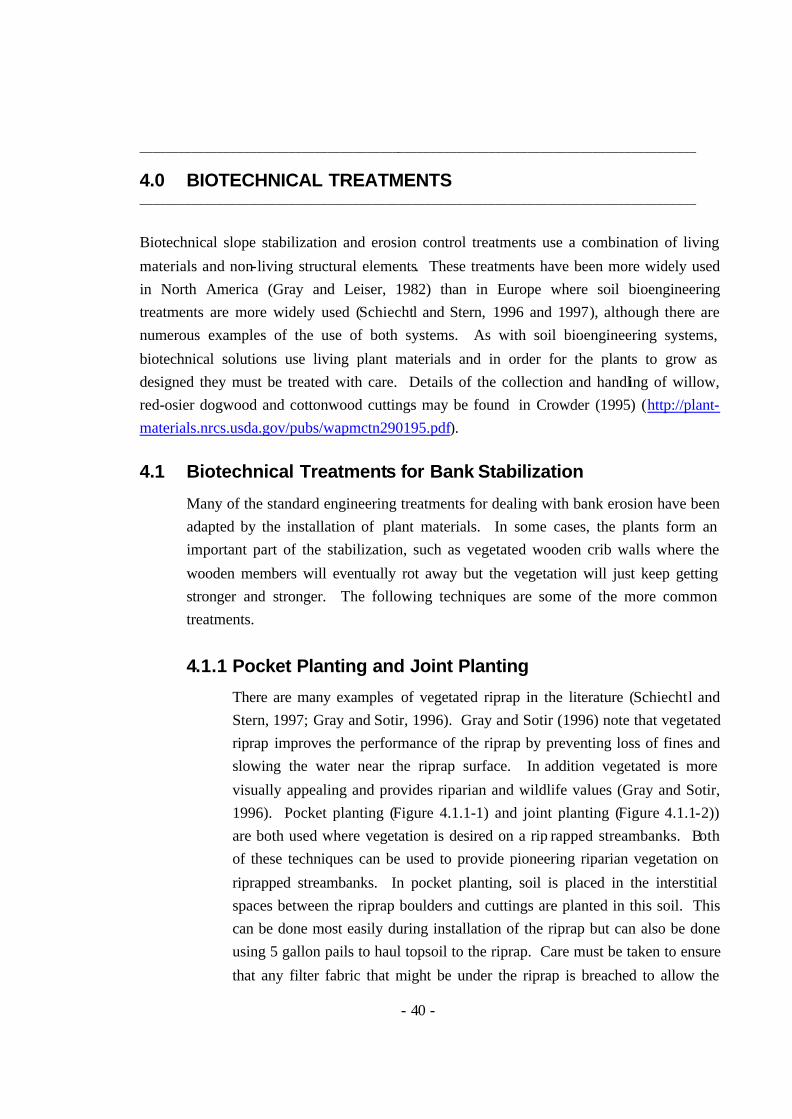
4.1.1 Pocket Planting and Joint Planting
There are many examples of vegetated riprap in the literature (Schiechtl and Stern, 1997; Gray and Sotir, 1996). Gray and Sotir (1996) note that vegetated riprap improves the performance of the riprap by preventing loss of fines and slowing the water near the riprap surface. In addition vegetated is more
visually appealing and provides riparian and wildlife values (Gray and Sotir, 1996). Pocket planting (Figure 4.1.1-1) and joint planting (Figure 4.1.1-2)) are both used where vegetation is desired on a rip rapped streambanks. Both of these techniques can be used to provide pioneering riparian vegetation on
riprapped streambanks. In pocket planting, soil is placed in the interstitial spaces between the riprap boulders and cuttings are planted in this soil. This can be done most easily during installation of the riprap but can also be done using 5 gallon pails to haul topsoil to the riprap. Care must be taken to ensure
that any filter fabric that might be under the riprap is breached to allow the
- 41 -
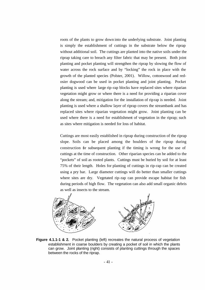
roots of the plants to grow down into the underlying substrate. Joint planting is simply the establishment of cuttings in the substrate below the riprap
without additional soil. The cuttings are planted into the native soils under the riprap taking care to breach any filter fabric that may be present. Both joint planting and pocket planting will strengthen the riprap by slowing the flow of water across the rock surface and by “locking” the rock in place with the
growth of the planted species (Polster, 2001). Willow, cottonwood and red-osier dogwood can be used in pocket planting and joint planting. Pocket planting is used where large rip-rap blocks have replaced sites where riparian vegetation might grow or where there is a need for providing a riparian cover
along the stream; and, mitigation for the installation of rip rap is needed. Joint planting is used where a shallow layer of riprap covers the streambank and has replaced sites where riparian vegetation might grow. Joint planting can be used where there is a need for establishment of vegetation in the riprap; such
as sites where mitigation is needed for loss of habitat. Cuttings are most easily established in riprap during construction of the riprap slope. Soils can be placed among the boulders of the riprap during
construction for subsequent planting if the timing is wrong for the use of cuttings at the time of construction. Other riparian species can be added to the “pockets” of soil as rooted plants. Cuttings must be buried by soil for at least 75% of their length. Holes for planting of cuttings in rip-rap can be created
using a pry bar. Large diameter cuttings will do better than smaller cuttings where sites are dry. Vegetated rip-rap can provide escape habitat for fish during periods of high flow. The vegetation can also add small organic debris as well as insects to the stream.
Figure 4.1.1-1 & 2. Pocket planting (left) recreates the natural process of vegetation establishment in coarse boulders by creating a pocket of soil in which the plants can grow. Joint planting (right) consists of planting cuttings through the spaces between the rocks of the riprap.
- 42 -
4.1.2 Vegetated Crib Walls
Vegetated crib walls (Figure 4.1.2-1) come in all shapes and sizes and may be constructed of a wide variety of materials. Where substantial bank
support is expected of the crib wall or where stream conditions are severe, a detailed engineering design should be obtained before proceeding. However, if the banks are low and the conditions are benign, simple log cribs can be readily constructed and vegetated. Logs or other material are
constructed in a “log cabin” fashion with large gaps between the logs. When the first course has been installed cuttings are placed between the elements of the wall and the cribs are backfilled with soil. Successive layers are constructed in a similar manner (Schiechtl and Stern, 1996).
Cribbing can be made of living plant materials such as cottonwood logs to provide additional plant materials to sprout and grow.
Figure 4.1.2-1. Vegetated crib walls can be constructed of a variety of materials and
can be small and simple or large and complex (from Schiechtl and Stern, 1996).
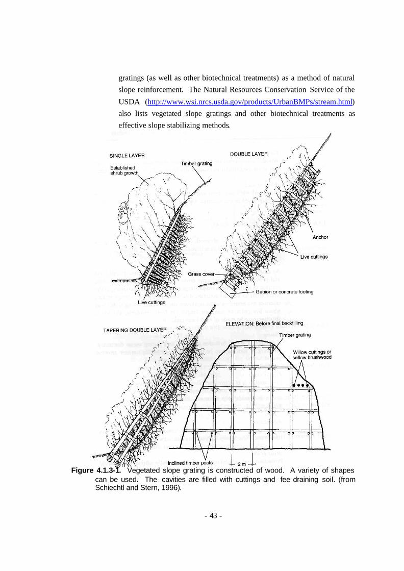
4.1.3 Vegetated Slope Gratings
Vegetated slope gratings (Figure 4.1.3-1) are large wooden structures that
are constructed where slopes have failed. The wooden elements provide a structure to support the slope while the vegetation becomes established. The International Society for Soil Mechanics and Geotechnical Engineering (http://tc17.poly.edu/natural.html) notes vegetated slope
- 43 -
gratings (as well as other biotechnical treatments) as a method of natural slope reinforcement. The Natural Resources Conservation Service of the
USDA (http://www.wsi.nrcs.usda.gov/products/UrbanBMPs/stream.html) also lists vegetated slope gratings and other biotechnical treatments as effective slope stabilizing methods.
Figure 4.1.3-1. Vegetated slope grating is constructed of wood. A variety of shapes
can be used. The cavities are filled with cuttings and fee draining soil. (from Schiechtl and Stern, 1996).
- 44 -
Vegetated slope gratings may be made of living cuttings (Schiechtl and Stern, 1996). For instance, large cottonwood posts such as are used for
live palisades could be used for construction of slope gratings. This would have the added advantage of providing additional cuttings that could take root and support the slope. In addition, using live materials would ensure the slope grating did not rot as the cuttings would sprout and grow.
4.2 Non-Woody Biotechnical Systems
There are a variety of non-woody biotechnical systems for streambank stabilization. Muhlberg and Moore (1998) suggest wrapping sods of shoreline sedges and grasses in a burlap wrap to revegetate shorelines.
Sod may be reinforced by placing galvanized mesh under the sod when it is laid. This technique increases the strength of the soil/plant interface (http://www.dot.state.oh.us/construction/OCA/Specs/2002CMS/Specbook2002/650%20roadsides/660.htm). A commercial product, “Enkamat”
provides a similar function using a non-woven plastic type material in which grass is grown (http://www.geosynthetics.colbond.com/home.html). Grass, sedge and other emergent aquatic species can be planted in coir rolls for treatment of relatively slow moving or stationary water to act as
protection from wave erosion (Allen and Leech, 1997) Plugs of grasses, sedges, as well as dicotyledonous plants and ferns can be planted in crib walls, bin walls and welded wire walls to soften the
appearance of these structures. Little strength is added by from the plants in these cases and there is no apparent advantage over the use of woody vegetation for such plantings.
The following sections present information on the hydrologic performance of the three classes of treatments discussed above and on specific treatment methods where such
information is available. This information is not to be used as a basis for design of
- 45 -
stabilization treatments which should be done by qualified professionals, but is provided to allow relative comparison between methods of treatment. This information is
preceded by a brief discussion of the erosional processes associated with shoreline erosion.
5.1 Shoreline Erosion Processes
Single particle erosion occurs with moving water when the shear stress of the
moving water exceeds the shear strength of the material against which the water is moving (Gray and Leiser, 1982). The shear stress of moving water is related to the velocity of the water as well as the volume of water that is moving while the shear strength of the material against which the water is acting is a combination of
a variety of factors. Erosion protection systems serve to either harden the surface against which the water is flowing (increase the shear strength) or to slow the movement of water across the surface to the point where substrate particles are not dislodged (slow the water velocity).
Movement of water down a gully or along in a stream results in erosion termed stream channel erosion. Stream channel erosion occurs on the stream bed through down cutting and along the banks through undercutting and sloughing. Streams,
and therefore stream channel erosion, can range in size from small flows in stable channels with very low rates of erosion to large rivers in active channels where erosion rates can be significant. The following five erosional processes are associated with stream channel erosion (from Gray and Leiser, 1982 ):
1. Toe undercutting – loss of material at the underwater toe of slope of the stream bank with subsequent slumping and remo val of the slumped material by the flowing water;
2. Bank erosion – erosion of bank materials (single particle erosion described above;
3. Bank sloughing – in addition to toe undercutting, bank sloughing can be caused by slumping of saturated materials which develop excess pore water pressure during rapid drawdown;
4. Flow slides – liquefaction of banks in saturated fine textured silts and sands; and
5. Piping – erosion of bank materials due to groundwater discharge and seepage zones.
- 46 -
Where water bodies are large enough so waves are generated by wind (or boats), wave action can cause significant erosion. Wave erosion occurs as a result of a
variety of processes. As the wave crashes onto the shore, the energy of the water falling from the crest of the wave to the beach is dissipated in part through erosion of the shore. In addition, the flow of water back and forth over the beach can loosen and remove particles. Where wave hit the beach at an oblique angle flows
along the shore of a water body develop and can carry soil particles over great distances (long shore drift). In addition to erosion caused directly by waves, waves may carry logs and other large woody debris that bashes into the banks and causes the physical dislodgement of soil materials (Polster, 2001). Waves may
also cause pore pressure fluctuations that result in weakening of soil cohesion to the point where the soils are easily eroded or slump with the slumped materials being eroded away (Gray and Sotir, 1996).
With any system that protects a material that can be easily eroded, care must be taken to ensure the placement of the system is such that high flows do not “out-flank” the protection. There are numerous examples of sites where erosion is occurring either upstream or downstream of protection, putting the whole
protection system in danger of failure.
5.2 Engineering Treatments
The hydrologic performance of engineering treatments is relatively well understood. Although a detailed review of the hydrologic characteristics of
various engineering treatments is beyond the scope of this report, a summary of the salient features of the hydrologic performance of some of the more common treatments is provided in the following sections.
5.2.1 Riprap
Riprap is the most common bank stabilization technique (Gray and Sotir, 1996) so the performance of other techniques can be reasonably compared with riprap. Although there are a number of design parameters that go into the development of an effective riprap design (Transportation
Association of Canada, 2001), simple measures of stone size vs. flow velocities provide an effective means of gauging the suitability of riprap as
- 47 -
a stabilization technique . Figure 5.2.1-1 provides a simple means of determining stone size given the velocity of the stream.
Figure 5.2.1-1
Velocity and Resistive Stone Size (from Gray and Leiser, 1982)
It should be noted that the average velocity of the stream is greater than the impingement velocity as the dynamics of flow dictate that velocities
slow along the shore and on the bottom of the stream relative to the centre of flow. Riprap design parameters for stream banks therefore differ from a bridge pier that is located in the centre of flow. Figure 5.2.1-1 also shows that the slope upon which the riprap is placed influences the size of
- 48 -
the rock that is needed. Size grading of the rock as well as bedding are important criteria in riprap design.
5.2.2 Cast Concrete Systems
Cast concrete systems of shoreline protection are reported by the manufacturer to be able to protect the shore against “high-velocity flows” (http://www.specblockusa.com/armortec/ajacks.cfm). These systems
provide a durable surface against which the water flows or the waves pound. In the case of the “A-jacks” system, the structure of the system dissipates the energy of the waves although without adequate protection under the structure, erosion of fine textured materials will occur. As with
riprap, there is a need to provide a good filter layer below the protection to prevent the loss of fines. Cast in place concrete spillways and other such structures are able to
provide serviceable protection against erosion in very severe conditions for many decades. Such systems must be designed by an experienced professional qualified for such designs.
5.2.3 Sheet Piling
Sheet piling, like cast in place concrete systems provides a non-erosive surface against which the water flows. Presumably, sheet piling protection systems can protect against extreme flow velocities because unless there is something to corrode the material used for the pilings the rate of erosion
of the material from the water alone is so slow as to be negligible.
5.3 Soil Bioengineering Treatments
Soil bioengineering systems to protect against streambank erosion need to be positioned so that they will sprout and grow, otherwise the materials used in the
structures will rot and fail. This means that the above ground portion of the structures must be above the waterline for much of the growing season as well as most of the dormant season. Of course periodic flooding such as during spring break-up is tolerated by most of the species used in soil bioengineering
treatments. Similarly, the streambed and the toe of slopes protected by soil
- 49 -
bioengineering systems must also be protected from erosion or the system above will fail (Allen and Leech, 1997).
Most soil bioengineering systems (live gravel bar staking, brush mattresses and live siltation) operate by slowing the flow of the water to the point where erosion is insignificant and in fact, deposition of bedload occurs. Donat (1995) provides a
description of the effects of woody vegetation along a stream channel on flow velocities. Figure 5.3-1 shows the changes in flow velocity distribution with a woody vegetation cover vs. a cover of grasses only. Donat (1995) notes that the streambank vegetation must be flexible and must have a uniform distribution to be
effective. In addition, the root systems of bank vegetation help to hold the bank in place against erosion. The following discussion on hydrologic performance of soil bioengineering
systems focuses on those systems that might be directly applied in flowing water situations.
Figure 5.3-1. Effects of flexible, well rooted or deeply planted bank vegetation on flow
velocity distribution (from Donat, 1995).
5.3.1 Brush Mattresses
Brush mattresses act to slow the flow of water across the surface of the potentially eroding streambank. By creating an area of non- flowing water immediately adjacent to the soil of the bank, the brush mattress protects the surface from erosion, even in situations were flow velocities are high.
However, where there is a danger of large woody debris scraping against
- 50 -
the bank, some more substantial protection such as protruding root wads or rock groins, must be provided to protect the brush mattress until the
plants can become fully established.
Figure 5.3.1-1. Brush mattresses (brush layers and live palisades are also shown)
serve to slow the flow of water adjacent to the streambank. Toe protection is needed to protect the soil bioengineered slope from being undercut (from Polster, 2002).
Brush mattresses have been used in the Alps (Italy) in a stream with a
boulder-step morphology suggesting flow velocities of 5 or more m/s although no flow measurements are given (Schiechtl and Stern, 1997). Muhlberg and Moore (1998) show a combination of brush mattress and live siltation (see below) being used on a stream called “Deep Creek” in
Alaska that has whitewater and is suspected of having flow velocities of more than 5 m/s. Again, no mention is given of flow velocities (Muhlberg and Moore, 1998).
5.3.2 Live Bank Protection
Live bank protection acts like sheet piling or articulated cast concrete blocks by protecting the surface from erosion by providing a durable surface against which the water flows. Photograph 5.3.2-1 shows a section of live bank protection along a mountain creek that has sustained
- 51 -
substantial flows. Again no flow velocity information is given (Polster, 2001.)
Photograph 5.3.2-1. Live bank protection is used to prevent erosion of bank sediments.
The small woody debris collected on the top of the bench formed by the live bank protection after high winter flows. No stream velocity information is given (from Polster, 2001).
5.3.3 Live Siltation
Live siltation is used to secure the toe of an eroding slope (Muhlberg and Moore, 1998). The large number of cuttings used in live siltation slows
the flow of water against the bank allowing silt to settle (hence the name) and prevents bank erosion. The cuttings are buried well into the bank at the normal high water level. Muhlberg and Moore (1998) recommend burial of at least 60 cm (2 feet). This ensures that the cuttings do not wash
out during high flows. Muhlberg and Moore (1998) show live siltation in use on a large stream in Alaska where whitewater can be seen suggesting flow velocities of greater than 5 m/s.
- 52 -
5.3.4 Live Gravel Bar Staking
Systems such as live gravel bar staking (Photograph 2.2-2) are designed specifically to deal with high flow situations. Live gravel bar staking acts
by creating surface roughness on the bed over which flood waters must flow. The cuttings trap small woody debris, adding to the roughness. This in turn slows the flow, allowing sediment to be deposited. Photograph 5.3.4-1 shows deposition of about 80 cm of sandy sediment that was
deposited on a cobble gravel bar during the first high flow period following one season of growth of the cuttings. Flow velocities are estimated to have been between 4 and 6 m/s with volumes sufficient to move a 2 m dbh Sitka Spruce log onto the bar 3 years after Photograph
5.3.4-1 was taken. Live gravel bar staking requires that the treated sites be above the average low water level for most of the growing season. Sites where the operation of impoundments precludes such timing are not successful candidates for live gravel bar staking.
Photograph 5.3.4-1. Over 80 cm of sediment was deposited on this gravel bar on the
San Juan River following live gravel bar staking (from Polster, 2001).
- 53 -
5.4 Biotechnical Treatments
Most biotechnical stabilization treatments utilize the engineering component to provide the erosion resistance (Muhlberg and Moore, 1998; Eubanks and
Meadows, 2002; Bentrup and Hoag, 1998; Allen and Leech, 1997). The ability of these systems to resist the erosive force of stream flows therefore depends on the adequacy of the engineering design. In some cases (Gray and Sotir, 1996) structures built of wood (cribbing and similar structures) are designed to
withstand the erosive forces until the vegetation that has been planted with the structures can take over this function. In the case of vegetated riprap, improved hydraulic performance is achieved by adding the vegetation over that of unvegetated riprap (Gray and Sotir, 1996; Schiechtl and Stern, 1997). The
vegetation locks the rock in place as well as slowing the flow across the surface of the riprap, preventing loss of stones during periods of high flow. Growth of woody plants around rocks in a riprap develops to lock the stones in place rather than displace them. Numerous examples of stones encased by roots or stems of
woody plants can be found showing this phenomenon. In addition to providing strength to the riprap system, woody vegetation enhances the habitat values of the rock slope.
Good engineering design in concert with effective use of vegetation is essential for biotechnical solutions to function properly. This is particularly critical during the early years of a project when the increased strength provided by the vegetation has yet to develop. Examples of biotechnical treatments where rock revetments
are used to protect against erosion should be developed by an engineer or hydrologist with experience in the design of such systems. Allen and Leech (1997) provide a table suggesting that for flow velocities over about 1 m/s (3.1 fps) treatments should be dominated by large root wads and rock (Table 5.4-1). It
is important to note that Allen and Leech (1997) use the term bioengineering rather loosely and the structures described in their report and presented in Table 5.4-1 would, in the context of this report be considered biotechnical solutions. Notwithstanding the flow restriction given by Allen and Leech (1997) of 1 m/s,
there are many illustrations of biotechnical solutions in areas where stream flows are much greater than 1 m/s (Muhlberg and Moore, 1998). As with soil bioengineering solutions, the plants that are used in biotechnical solutions must be able to grow over most of the growing season without being covered by water.
- 54 -
Table 5.4-1 Flow Velocity Table from Allen and Leech (1997)
There are a wide variety of bank stabilization treatments available for use in restoring degraded stream and river banks. Soil bioengineering and biotechnical treatments can be as effective as traditional engineering solutions to erosion and bank instability. Where vegetation is used for stabilizing degraded slopes, the added advantages of enhancement
of riparian habitats is an inducement to incorporate these techniques in new construction projects and repairs. In many cases, the application of riprap for bank stabilization is simply conducted without looking at appropriate alternatives because that is the way it has always been done. Opportunities are available to enhance riparian ecosystems with
bank repairs and new developments. These need to be taken to avoid further habitat loss and degradation.
- 55 -
LITERATURE CITED
Allen, H.H. and J.R. Leech. 1997. Bioengineering for streambank erosion control; Report
1, Guidelines. Technical Report EL-97-8. U.S. Army Engineer Experimental Waterway Experimental Station. Vicksburg, MS. 90 pp.
Alberta Infrastructure. 1999. Fish Habitat Manual Guidelines and Procedures for
Watercourse Crossings in Alberta. Queens Printer. Edmonton, Alberta Bentrup, G. and J.C. Hoag. 1998. The Practical Streambank Bioengineering Guide.
Brayshaw, T.C. 1996. Catkin-bearing Plants of British Columbia. Royal British
Columbia Museum. Victoria, B.C. 213 pp. Crowder, W. 1995. Collecting willow, poplar and redosier (sic) dogwood hardwood
cuttings for riparian site plantings. USDA Natural Resources Conservation Service Plant Materials Program Technical Note # 29. Spokane Washington.
Donat, M. 1995. Bioengineering Techniques for Streambank Restoration: A review of
central European Practices. Watershed Restoration Project Report No. 2. British Columbia Ministry of Environment, Lands and Parks. University of British Columbia. Vancouver, B.C. Canada. 86 pp.
Eubanks, C.E. and D. Meadows. 2002. A soil bioengineering guide for streambank and
lakeshore stabilization. U.S.D.A. Forest Service. San Dimas, California. 187 pp. Gray, D.H. and A.T. Leiser. 1982. Biotechnical Slope Protection and Erosion Control.
Van Nostrand Reinhold Company Inc. Scarborough, Ontario, 271 pp. (reprinted by Krieger Publishing Co. Malabar, Florida).
Gray, D.H. and R. B. Sotir. 1996. Biotechnical and Soil Bioengineering Slope
Stabilization: A practical guide for erosion control. John Wiley & Sons, Inc. New York, New York, 378 pp.
Howell, J. 1999. Roadside Bio -engineering Reference Manual. His Majesty’s
Government of Nepal, Department of Roads Babar Mahal, Kathmandu, Nepal. 216 pp.
Lewis, L. 2000. Soil Bioengineering An Alternative for Roadside Management A
practical guide. USDA Forest Service Technology and Development Program. 7700 Transportation Management. 0077 1801 – SDTDC. San Dimas, California. 47 pp.
- 56 -
Lewis, L., S L. Salisbury and S. Hagen. 2001. Soil bioengineering for upland slope stabilization. Research Report. Research Project WA-RD 491.1 Soil Bioengineering for Slopes. Washington State Transportation Center. University of Washington. Olympia, Washington. http://depts.washington.edu/trac/bulkdisk/pdf/491.1.pdf
McCullah, J.A. 2000. Bio Draw 1.0. Compendium of Biotechnical Soil Stabilization
Solutions. CD of drawings and te chnical descriptions. Salix Applied Earthcare. Redding, California, USA. www.biodraw.com
Mitchell, J. and L. Dyck. 2000. Materials and Techniques for Live Staking Plants onto
Reservoir Shorelines. from the Southern Division of the American Fisheries Society Midyear Meeting held February 3–6, 2000 in Savannah, Georgia. http://www.sdafs.org/meetings/00sdafs/symagend.htm
Muhlberg, G.A. and N.J. Moore. 1998. Streambank revegetation and protection a guide
for Alaska. Technical Report No. 98-3. Alaska Department of Fish and Game. Alaska Departmetn of Natural Resources. US Environmental Protection Agency. 57 pp.
Polster, D.F. 1989. Successional reclamation in Western Canada: New light on an old
subject. Paper presented at the Canadian Land Reclamation Association and American Society for Surface Mining and Reclamation conference, Calgary, Alberta, August 27-31, 1989.
Polster, D.F. 1991. Natural Vegetation Succession and Sustainable Reclamation. paper
presented at the Canadian Land Reclamation Association / B.C. Technical and Research Committee on Reclamation symposium. Kamloops, B.C. June 24 - 28, 1991.
Polster, D.F. 1997. Restoration of landslides and unstable slopes: Considerations for
bioengineering in Interior locations. Paper presented at the 21st Annual B.C. Mine Reclamation Symposium and the 22nd Annual Canadian Land Reclamation Association Meeting. Cranbrook, B.C. September 22 – 25, 1997.
Polster, D.F. 1999a. Soil Bioengineering for Steep / Unstable Slopes and Riparian
Restoration. Paper presented at the Fourth Annual Roads, Rails and Environment Workshop. November 2 – 3, 1999. Revelstoke, B.C.
Polster, D.F. 1999b. New Soil Bioengineering Techniques for Specific Problems. Poster
presented at the Interior Forest Sites Rehabilitation Workshop. April 7-8, 1999. Kamloops, B.C.
Polster, D.F. 2001. Soil Bioengineering for Forest Land Reclamation and Slope
Stabilization. Course materials for training professional and technical staff. Polster Environmental Services, September, 2001.
- 57 -
Polster, D.F. 2002. Soil Bioengineering Treatment for Erosion Control on the Argenta
Bend, Duncan River, British Columbia. unpublished report prepared for B.C. Hydro and Power Authority by Polster Environmental Services Ltd. 23 pp.
Schiechtl, H.M. and R. Stern. 1996. Ground Bioengineering Techniques for Slope
Protection and Erosion Control. Trans. By L. Jaklitsch. Blackwell Scientific. Oxford, U.K. 146 pp.
Schiechtl, H.M. and R. Stern. 1997. Water Bioengineering Techniques for Watercourse,
Bank and Shoreline Protection. Trans. By L. Jaklitsch. Blackwell Scientific. Oxford, U.K. 185 pp.
Schiereck, G. J. 2001. Introduction to bed, bank and shore protection. Delft University
Press, Postbus 98, 2600 MG Delft, Netherlands. Slaney, P.A. and D. Zaldokas, eds. 1997. Fish Habitat Rehabilitation Procedures.
Watershed Restoration Technical Circular No. 9. Watershed Restoration Program. Ministry of Environment, Lands and Parks. Vancouver, B.C.
Transportation Association of Canada. 2001. Guide to Bridge Hydraulics 2nd Ed.
Transportation Association of Canada. Ottawa, Ontario. 181 pp. Veri-Tech Inc. 1998. Streambank Stabilization Handbook. Veri-Tech Inc. Vicksburg,
MS. digital manual. http://www.veritechinc.com Walker, L.W. and R. del Moral. 2003. Primary Succession and Ecosystem Rehabilitation.
Cambridge University Press. Cambridge UK. 442 pp. Washington State Aquatic Habitat Guidelines Program. 2002. Integrated Streambank
Protection Guidelines. Washington Department of Fish and Wildlife, Department of Ecology, Department of Transportation, Department of the Army. Olympia, Washington. 226 pp plus appendices.