Altivar™ 71 Quick Reference Guide 12/2012 ALTIVAR 71 GRAPHIC DISPLAY TERMINAL E C B A F G H I K D RDY Term +0.00 Hz 0.0A 1 DRIVE MENU 1.1 SIMPLY START 1.2 MONITORING 1.3 SETTINGS 1.4 MOTOR CONTROL 1.5 INPUTS / OUTPUTS CFG Code << >> Quick Example of accessing the acceleration ramp setting RDY Term +0.00 Hz 0.0A 1 DRIVE MENU 1.1 SIMPLY START 1.2 MONITORING 1.3 SETTINGS 1.4 MOTOR CONTROL 1.5 INPUTS / OUTPUTS CFG Code << >> Quick ENT ESC RDY Term +0.00 Hz 0.0A 1.3 SETTINGS Ramp increment: 01 Acceleration 9.51 s Deceleration: 9.67 s Acceleration 2: 12.58 s Deceleration 2: 13.45 s Code << >> Quick ENT ENT or ESC RDY Term +0.00 Hz 0.0A Acceleration 9.51 s Min = 0.01 Max = 99.99 << >> Quick U / T1 V / T2 W / T3 R / L1 U1 W1 V1 M 3 a S / L2 T / L3 PWR +24 A1 R1A R1C R1B R2A R2C Line reactor (if used) Braking resistor (if used) Speed reference potentiometer, if used P0 PA / + PB PC / - 3 a LI1 LI5 +24 0V A1 ATV71Hppppp PWR +10 AI1+ AI2 AI1- COM COM AO1 LI3 LI2 LI6 LI4 0 ± 10 V or X-Y mA 3-phase power supply connection diagram Control connection diagram TYPICAL CONNECTIONS Description and Operation A Display status—displays default settings: the drive’s state, active control channels, frequency reference, and LOC/REM (T/K key status). The Display Status content can be configured. B Menu line—displays the name of the current menu or submenu. C Submenus—lists the submenus of the current menu. D Scroll boxes—indicates (by arrow direction) whether there are additional submenus or levels to access. A blank box indicates that there are no additional submenus or levels to access. E Status line—displays the functions assigned to function buttons F1–F4: Code (F1), << (F2), >> (F3), and T/K (F4). See the descriptions below. F Function buttons— F1: displays the code of the selected parameter or contextual Help F2: navigates to the left or returns to the previous menu or submenu F3: navigates to the right or advances to the next menu or submenu F4 (quick navigation button): provides a shortcut to menus or settings G Stop/Reset button—stops the drive controller and resets the faults when in HMI command mode H ESC button—exits a menu or parameter, or cancels a value to return to the previous value in the memory I Run button—runs the motor with the current setting. Starts the drive controller if in HMI command mode. J Navigation button/dial—pressing the button saves a value or enters a menu or parameter. Turning the dial clockwise increases a value or advances to the next menu item or line. Turning the dial counter- clockwise decreases a value or backs up to the previous menu item or line. In HMI mode, the dial acts as a speed reference control. K FWD/REV button—reverses the rotation direction of the motor (if configured to allow reverse for HMI command mode). NOTE: Refer to the Altivar 71 programming manual for detailed information about the display terminal operations. Changing a parameter 1. Use the navigation dial to vertically scroll the DRIVE MENU list, press ENT (navigation button) to select the submenu. 2. Select the parameter to change and press ENT. 3. Use F1 and F2 to scroll horizontally, then select the digit to change (the digit is highlighted). 4. Turn the navigation dial clockwise to increase the digit or counter-clockwise to decrease the digit. 5. Press ENT to save the change or press the ESC button to cancel the change. NOTE:Altivar 71 drive controllers come standard with a graphic keypad display terminal as well as a 7-segment, 4-digit integrated display terminal. The lower horsepower Altivar 71 drives can be ordered without the graphic keypad display terminal. NOTE: The Macro-Configuration factory setting is [Start/Stop] J Input/ output [Start/Stop] [M. handling] [Gen. Use] [Hoisting] [PID regul.] [Network C.] [Mast./ slave] AI1 [Ref.1 channel] [Ref.1 channel] [Ref.1 channel] [Ref.1 channel] [Ref.1 channel] (PID reference) [Ref.2 channel] ([Ref.1 channel] = integrated Modbus) (1) [Ref.1 channel] AI2 [No] [Summing ref. 2] [Summing ref. 2] [No] [PID feedback] [No] [Torque ref. 1] AO1 [No] [No] [No] [No] [No] [No] [No] R1 [No drive flt] [No drive flt] [No drive flt] [No drive flt] [No drive flt] [No drive flt] [No drive flt] R2 [No] [No] [No] [Brk control] [No] [No] [No] LI1 (2-wire) [Forward] [Forward] [Forward] [Forward] [Forward] [Forward] [Forward] LI2 (2-wire) [Reverse] [Reverse] [Reverse] [Reverse] [Reverse] [Reverse] [Reverse] LI3 (2-wire) [No] [2 preset speeds] [Jog] [Fault reset] [PID integral reset] [Ref2 switching] [Trq/spd switching] LI4 (2-wire) [No] [4 preset speeds] [Fault reset] [External fault] [2 preset PID ref.] [Fault reset] [Fault reset] LI5 (2-wire) [No] [8 preset speeds] [Torque limit] [No] [4 preset PID ref.] [No] [No] LI6 (2-wire) [No] [Fault reset] [No] [No] [No] [No] [No] LI1 (3-wire) Stop Stop Stop Stop Stop Stop Stop LI2 (3-wire) [Forward] [Forward] [Forward] [Forward] [Forward] [Forward] [Forward] LI3 (3-wire) [Reverse] [Reverse] [Reverse] [Reverse] [Reverse] [Reverse] [Reverse] LI4 (3-wire) [No] [2 preset speeds] [Jog] [Fault reset] [PID integral reset] [Ref. 2 switching] [Trq/spd switching] LI5 (3-wire) [No] [4 preset speeds] [Fault reset] [External fault] [2 preset PID ref.] [Fault reset] [Fault reset] LI6 (3-wire) [No] [8 preset speeds] [Torque limitation] [No] [4 preset PID ref.] [No] [No] Option cards LI7 to LI14 [No] [No] [No] [No] [No] [No] [No] LO1 to LO4 [No] [No] [No] [No] [No] [No] [No] R3/R4 [No] [No] [No] [No] [No] [No] [No] AI3, AI4 [No] [No] [No] [No] [No] [No] [No] RP [No] [No] [No] [No] [No] [No] [No] AO2 [I motor] [I motor] [I motor] [I motor] [I motor] [I motor] [I motor] AO3 [No] [Sign. torque] [No] [Sign. torque] [PID Output] [No] [Motor freq.] Graphic display terminal keys F1 key [No] [No] [No] [No] [No] Control via graphic display terminal [No] Keys F2, F3, F4 [No] [No] [No] [No] [No] [No] [No] In 3-wire control, the assignment of inputs LI1 to LI7 shifts. PROGRAMMING PARAMETERS MACRO CONFIGURATION PARAMETERS 8800HO1202 Replaces T8843PD0601EP R0, 11/2006 Electrical equipment should be installed, operated, serviced, and maintained only by qualified personnel. No responsibility is assumed by Schneider Electric for any consequences arising out of the use of this material.
Transcript
Altivar™ 71 Quick Reference Guide 12/2012
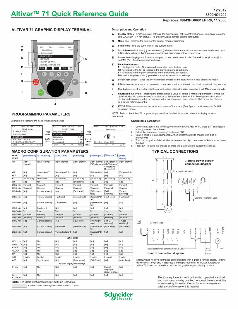
ALTIVAR 71 GRAPHIC DISPLAY TERMINAL
E
C
BA
F
G H
I K
D
RDY Term +0.00 Hz 0.0A
1 DRIVE MENU
1.1 SIMPLY START
1.2 MONITORING
1.3 SETTINGS
1.4 MOTOR CONTROL
1.5 INPUTS / OUTPUTS CFG
Code << >> Quick
Example of accessing the acceleration ramp setting
Description and OperationA Display status—displays default settings: the drive’s state, active control channels, frequency reference,
and LOC/REM (T/K key status). The Display Status content can be configured.
B Menu line—displays the name of the current menu or submenu.
C Submenus—lists the submenus of the current menu.
D Scroll boxes—indicates (by arrow direction) whether there are additional submenus or levels to access. A blank box indicates that there are no additional submenus or levels to access.
E Status line—displays the functions assigned to function buttons F1–F4: Code (F1), << (F2), >> (F3), and T/K (F4). See the descriptions below.
F Function buttons— F1: displays the code of the selected parameter or contextual HelpF2: navigates to the left or returns to the previous menu or submenuF3: navigates to the right or advances to the next menu or submenu F4 (quick navigation button): provides a shortcut to menus or settings
G Stop/Reset button—stops the drive controller and resets the faults when in HMI command mode
H ESC button—exits a menu or parameter, or cancels a value to return to the previous value in the memory
I Run button—runs the motor with the current setting. Starts the drive controller if in HMI command mode.
J Navigation button/dial—pressing the button saves a value or enters a menu or parameter. Turning the dial clockwise increases a value or advances to the next menu item or line. Turning the dial counter- clockwise decreases a value or backs up to the previous menu item or line. In HMI mode, the dial acts as a speed reference control.
K FWD/REV button—reverses the rotation direction of the motor (if configured to allow reverse for HMI command mode).
NOTE: Refer to the Altivar 71 programming manual for detailed information about the display terminal operations.
Changing a parameter
1. Use the navigation dial to vertically scroll the DRIVE MENU list, press ENT (navigation button) to select the submenu.
2. Select the parameter to change and press ENT.3. Use F1 and F2 to scroll horizontally, then select the digit to change (the digit is
highlighted).4. Turn the navigation dial clockwise to increase the digit or counter-clockwise to decrease
the digit.5. Press ENT to save the change or press the ESC button to cancel the change.
NOTE:Altivar 71 drive controllers come standard with a graphic keypad display terminal as well as a 7-segment, 4-digit integrated display terminal. The lower horsepower Altivar 71 drives can be ordered without the graphic keypad display terminal.
NOTE: The Macro-Configuration factory setting is [Start/Stop]
F1 key [No] [No] [No] [No] [No] Control via graphic display terminal
[No]
KeysF2, F3, F4
[No] [No] [No] [No] [No] [No] [No]
In 3-wire control, the assignment of inputs LI1 to LI7 shifts.
PROGRAMMING PARAMETERS
MACRO CONFIGURATION PARAMETERS
8800HO1202Replaces T8843PD0601EP R0, 11/2006
Electrical equipment should be installed, operated, serviced, and maintained only by qualified personnel. No responsibility is assumed by Schneider Electric for any consequencesarising out of the use of this material.
Word 1 add. select. : 0Format word 1 : HexWord 2 add. select : 0Format word 2 : HexWord 3 add. select : 0Format word 3 : HexWord 4 add. select : 0Format word 4 : Hex
Return Std name : NoPARAMETER SELECTIONCUSTOMIZED SELECTIONUSER MENU NAMEDEVICE NAMESERVICE MESSAGECONFIGURATION 0CONFIGURATION 1CONFIGURATION 2SERIAL NUMBER
PROTECTIONVISIBILITY
Status : UnlockedPIN code 1 : OFFPIN code 2 : OFFUpload rights : PermittedDownload rights : Unlock drv
Config. Source : Macro-ConfParameter Group ListGoto FACTORY SETTINGSSave config : No
Std. mot. freq : 60Hz NEMARated motor power : 1.0HPRated motor volt. : 460VRated motor current : 1.6ARated motor freq. : 60.0HzRated motor speed : 1725rpmMax frequency : 72.0HzAuto tuning : NoAutomatic autotune : NoAuto tuning status : Not doneOutput Ph rotation : ABCMotor control type : SVC VVector Control 2pt. : NoV. constant power : Freq. Const. power : Nominal I sync. : Nom motor spd sync : Pole pairs : Syn. EMF constant : Autotune L d-axis : Autotune L q-axis : Cust. Stator R syn : IR compensation : 100%Slip compensation : 100%Power Identification : IP20Stator R measured : 5881mOhmIdr : 1.0ALfr : 34.08mHT2r : 74msNominal motor slip : 3.4HzPr : 2R1w : 5881mOhmIdw : 1.0ALfw : 34.08mHT2w : 74msR1rs : mOhmNominal Freq sync. : HzEncoder Type : AABBNumber of pulses : 1024Encoder check : NoEncoder usage : No ENA system : NoENA prop. gain : 250ENA integral gain : 100Reduction ratio : 10Sinus filter : NoSwitching freq. : 12kHzCurrent Limitation : 2.7ANoise Reduction : YesMotor surge limit. : NoVolt surg limit. opt : 10usBraking level : 785VBraking balance : NoLoad sharing : NoLoad correction : 0Correction min spd : 0Correction max spd : 0.1Torque offset : 0%Sharing filter : 100ms
MAIN MENU 1 DRIVE MENU
2 ACCESS LEVEL
3 OPEN / SAVE AS
4 PASSWORD
5 LANGUAGE
6 MONITORING CONFIG
7 DISPLAY CONFIG
7.1 USER PARAMETERS
7.2 USER MENU
7.3 PARAMETER ACCESS
Keypad contrast: 50%Keypad stand-by: 5minPower up menu: Main menu
7.4 KEYPAD PARAMETERS
6.3 COM. MAP CONFIG.
6.2 MONITOR SCREEN TYPE
6.1 PARAM. BAR SELECT MONITORING
1.2 MONITORING
1.3 SETTINGS 1.7 APPLICATION FUNCT.
1.8 FAULT MANAGEMENT
1.6 COMMAND
1.10 DIAGNOSTICS
1.11 IDENTIFICATION
1.12 FACTORY SETTINGS
1.13 USER MENU
1.14 PROGRAMMABLE CARD
1.9 COMMUNICATION
NOTE:• The key drive settings to monitor are highlighted in yellow.
Refer to the Altivar 71 programming manual for additional programming instructions.
• All menu levels are accessible through the Expert access level.
2/3 wire control : 2 wireMacro config. : Start/Stop(Customized Macro) : (Yes)Std. mot. freq : 60Hz NEMAInput phase loss (1ph) : No (1ph)Rated motor Power : 1.0HRated motor volt. : 460VRated motor current : 1.6ARated motor freq. : 60.0HzRated motor speed : 1725rpmMax. frequency : 72.0HzAuto.tuning : NoAuto.tuning status : Not doneOutput Ph rotation : ABCMot. therm. Current : 1.6AAcceleration : 3.00SDeceleration : 3.00SLow speed : 0.0HzHigh speed : 60.0Hz
I/O MAPPROG. CARD I/O MAP COMMUNICATION MAPAlarm groups : ---HMI Frequency ref. : 0.0HzInternal PID ref. : HMI torque ref. : 0% Multiplying coeff. : 0% Frequency ref. : 0.0HzTorque ref. : 0%Output Frequency : 0.0HzMotor current : 0.0AENA avg speed : 0.0HzMotor speed : 0 rpmMotor voltage : 0VMotor power : 0%Motor torque : 0.0%Mains voltage : 0V Motor thermal state : 0%Drv. thermal state : 38%DBR. thermal state : 0% Consumption : 0WhRun time : 0sPower on time : 0hIGBT alarm counter : 0sPID ref. : PID feedback : PID error : PID Output : Date/Time : Applic card word 2,3,4,5,6 : Config. Active : Config. n°0Utilised param. set : 1, 2 or 3ALARMSOTHER STATUS
1.1 SIMPLY START
1.4 MOTOR CONTROL
1.5 INPUTS/OUTPUTS CFG
Reference SwitchRef. OperationsRampStop ConfigurationAuto DC InjectionJOGPreset Speeds+/- Speed+/- Speed Around Ref.Memo ReferenceFluxing By LILimit switchesBrake logic control External weight meas.High speed hoistingPID RegulatorPID Preset ReferencesTorque control Sleeping / Wake UpTorque Limitation2nd Current Limit.Line Contactor CommandOutput Contactor CommandPositioning by sensorsParam. Set SwitchingMultimotors / Config.Auto Tuning By LITraverse control