NOTICERead these instructions carefully, and look at the equipment to become familiar with the device before trying to install, operate, service, or maintain it. The following special messages may appear throughout this documentation or on the equipment to warn of potential hazards or to call attention to information that clarifies or simplifies a procedure.
PLEASE NOTEElectrical equipment should be installed, operated, serviced, and maintained only by qualified personnel. No responsibility is assumed by Schneider Electric for any consequences arising out of the use of this material.A qualified person is one who has skills and knowledge related to the construction and operation of electrical equipment and its installation, and has received safety training to recognize and avoid the hazards involved.
Qualification Of PersonnelOnly appropriately trained persons who are familiar with and understand the contents of this manual and all other pertinent product documentation are authorized to work on and with this product. In addition, these persons must have received safety training to recognize and avoid hazards involved. These persons must have sufficient technical training, knowledge and experience and be able to foresee and detect potential hazards that may be caused by using the product, by changing the settings and by the mechanical, electrical and electronic equipment of the entire system in which the product is used. All persons working on and with the product must be fully familiar with all applicable standards, directives, and accident prevention regulations when performing such work.
6 QGH39563 02/2017
Intended UseThis product is a drive for three-phase synchronous and asynchronous motors and intended for industrial use according to this manual.The product may only be used in compliance with all applicable safety regulations and directives, the specified requirements and the technical data.Prior to using the product, you must perform a risk assessment in view of the planned application. Based on the results, the appropriate safety measures must be implemented.Since the product is used as a component in an entire system, you must ensure the safety of persons by means of the design of this entire system (for example, machine design). Any use other than the use explicitly permitted is prohibited and can result in hazards. Electrical equipment should be installed, operated, serviced, and maintained only by qualified personnel.
Product Related InformationRead and understand these instructions before performing any procedure with this drive.
Drive systems may perform unexpected movements because of incorrect wiring, incorrect settings, incorrect data or other errors.
DANGERHAZARD OF ELECTRIC SHOCK, EXPLOSION OR ARC FLASH Only appropriately trained persons who are familiar with and understand the contents of this manual
and all other pertinent product documentation and who have received safety training to recognize and avoid hazards involved are authorized to work on and with this drive system. Installation, adjustment, repair and maintenance must be performed by qualified personnel.
The system integrator is responsible for compliance with all local and national electrical code requirements as well as all other applicable regulations with respect to grounding of all equipment.
Many components of the product, including the printed circuit boards, operate with mains voltage. Do not touch.
Only use properly rated, electrically insulated tools and measuring equipment. Do not touch unshielded components or terminals with voltage present. Motors can generate voltage when the shaft is rotated. Prior to performing any type of work on the
drive system, block the motor shaft to prevent rotation. AC voltage can couple voltage to unused conductors in the motor cable. Insulate both ends of unused
conductors of the motor cable. Do not short across the DC bus terminals or the DC bus capacitors or the braking resistor terminals. Before performing work on the drive system: Disconnect all power, including external control power that may be present. Place a Do Not Turn On label on all power switches related to the drive system. Lock all power switches in the open position. Wait 15 minutes to allow the DC bus capacitors to discharge. Follow the instructions given in the chapter "Verifying the Absence of Voltage" in the installation
manual of the product. Before applying voltage to the drive system: Verify that the work has been completed and that the entire installation cannot cause hazards. If the mains input terminals and the motor output terminals have been grounded and short-circuited,
remove the ground and the short circuits on the mains input terminals and the motor output terminals.
Verify proper grounding of all equipment. Verify that all protective equipment such as covers, doors, grids is installed and/or closed.
Failure to follow these instructions will result in death or serious injury.
WARNINGUNANTICIPATED EQUIPMENT OPERATION Carefully install the wiring in accordance with the EMC requirements. Do not operate the product with unknown or unsuitable settings or data. Perform a comprehensive commissioning test.Failure to follow these instructions can result in death, serious injury, or equipment damage.
QGH39563 02/2017 7
Damaged products or accessories may cause electric shock or unanticipated equipment operation.
Contact your local Schneider Electric sales office if you detect any damage whatsoever.
(1) For USA: Additional information, refer to NEMA ICS 1.1 (latest edition), Safety Guidelines for the Application, Installation, and Maintenance of Solid State Control and to NEMA ICS 7.1 (latest edition), Safety Standards for Construction and Guide for Selection, Installation and Operation of Adjustable-Speed Drive Systems.
The temperature of the products described in this manual may exceed 80 °C (176 °F) during operation.
This equipment has been designed to operate outside of any hazardous location. Only install this equipment in zones known to be free of a hazardous atmosphere.
DANGERELECTRIC SHOCK OR UNANTICIPATED EQUIPMENT OPERATIONDo not use damaged products or accessories.Failure to follow these instructions will result in death or serious injury.
WARNINGLOSS OF CONTROL The designer of any control scheme must consider the potential failure modes of control paths and,
for critical control functions, provide a means to achieve a safe state during and after a path failure. Examples of critical control functions are emergency stop, overtravel stop, power outage and restart.
Separate or redundant control paths must be provided for critical control functions. System control paths may include communication links. Consideration must be given to the
implications of unanticipated transmission delays or failures of the link. Observe all accident prevention regulations and local safety guidelines (1). Each implementation of the product must be individually and thoroughly tested for proper operation
before being placed into service.Failure to follow these instructions can result in death, serious injury, or equipment damage.
NOTICEDESTRUCTION DUE TO INCORRECT MAINS VOLTAGEBefore switching on and configuring the product, verify that it is approved for the mains voltageFailure to follow these instructions can result in equipment damage.
WARNINGHOT SURFACES Ensure that any contact with hot surfaces is avoided. Do not allow flammable or heat-sensitive parts in the immediate vicinity of hot surfaces. Verify that the product has sufficiently cooled down before handling it. Verify that the heat dissipation is sufficient by performing a test run under maximum load conditions.Failure to follow these instructions can result in death, serious injury, or equipment damage.
DANGERPOTENTIAL FOR EXPLOSIONInstall and use this equipment in non-hazardous locations only.Failure to follow these instructions will result in death or serious injury.
8 QGH39563 02/2017
QGH39563 02/2017 9
About the Book
At a Glance
Document ScopeThe document provides the information about migration from ATV312 to ATV320.
Validity NoteThis documentation is valid for ATV320 devices which support device conversion.The technical characteristics of the devices described in this document also appear online. To access this information online:
The characteristics that are presented in this manual should be the same as those characteristics that appear online. In line with our policy of constant improvement, we may revise content over time to improve clarity and accuracy. If you see a difference between the manual and online information, use the online information as your reference.
Step Action1 Go to the Schneider Electric home page www.schneider-electric.com.2 In the Search box type the reference of a product or the name of a product range.
Do not include blank spaces in the reference or product range. To get information on grouping similar modules, use asterisks (*).
3 If you entered a reference, go to the Product Datasheets search results and click on the reference that interests you.If you entered the name of a product range, go to the Product Ranges search results and click on the product range that interests you.
4 If more than one reference appears in the Products search results, click on the reference that interests you.
5 Depending on the size of your screen, you may need to scroll down to see the data sheet.6 To save or print a data sheet as a .pdf file, click Download XXX product datasheet.
Related DocumentsUse your tablet or your PC to quickly access detailed and comprehensive information on all our products on www.schneider-electric.comThe Internet site provides the information you need for products and solutions The whole catalog for detailed characteristics and selection guides The CAD files to help design your installation, available in over 20 different file formats All software and firmware to maintain your installation up to date A large quantity of White Papers, Environment documents, Application solutions, Specifications... to
gain a better understanding of our electrical systems and equipment or automation And finally all the User Guides related to your drive, listed below:
You can download these technical publications and other technical information from our website at http://www.schneider-electric.com/ww/en/download
Title of Documentation Reference NumberATV320 Getting Started NVE21763 (English), NVE21771 (French),
TerminologyThe technical terms, terminology, and the corresponding descriptions in this manual normally use the terms or definitions in the relevant standards.In the area of drive systems this includes, but is not limited to, terms such as error, error message, failure, fault, fault reset, protection, safe state, safety function, warning, warning message, and so on.Among others, these standards include: IEC 61800 series: Adjustable speed electrical power drive systems IEC 61508 Ed.2 series: Functional safety of electrical/electronic/programmable electronic safety-related EN 954-1 Safety of machinery - Safety related parts of control systems EN ISO 13849-1 & 2 Safety of machinery - Safety related parts of control systems. IEC 61158 series: Industrial communication networks - Fieldbus specifications IEC 61784 series: Industrial communication networks - Profiles IEC 60204-1: Safety of machinery - Electrical equipment of machines – Part 1: General requirementsIn addition, the term zone of operation is used in conjunction with the description of specific hazards, and is defined as it is for a hazard zone or danger zone in the EC Machinery Directive (2006/42/EC) and in ISO 12100-1.
12 QGH39563 02/2017
QGH39563 02/2017 13
Altivar Machine ATV320Introduction to Device Conversion FunctionQGH39563 02/2017
Introduction to Device Conversion Function
Chapter 1Introduction to Device Conversion Function
Device Conversion
OverviewDevice conversion allows you to convert the configuration (.psx file) of one device (source device) to another device (target device).For example: The ATV312 configuration can be used as ATV320 configuration after the device conversion operation.NOTE: The device conversion function is available only in the SoMove FDT container.The table provides the list of devices which support device conversion
Pre-ConditionInstall SoMove FDT on your PC.
From Source Device To Target DeviceATV32 ATV320ATV312 ATV320
WARNINGUNANTICIPATED EQUIPMENT OPERATIONDevice conversion function is used to apply the configuration from a drive product range to another drive product range. However, the values of certain parameters cannot be applied because the functional behaviors of the source drive and the target drive are different.The parameters whose values cannot be applied are kept to the factory settings. Consult the programming manual for the parameters that are kept to their factory settings and select
appropriate values for these parameters. Do not operate the product with unknown or unsuitable settings or data. Perform a comprehensive commissioning test.Failure to follow these instructions can result in death, serious injury, or equipment damage.
Introduction to Device Conversion Function
14 QGH39563 02/2017
Conversion of Device ConfigurationThe table provides the procedure to convert the device configuration
Step Action Comments1 On the SoMove start page, do one of the following
Click the Device Conversion button Press CTRL + ALT + Q keys, on the menu bar, click
1. Click the button in the Source zoneResult: Opens the Select device configuration dialog box
2. In the Select device configuration dialog box, select the configuration file (.psx) you wish to convert and then click Open
3. Select the target device in Select Target DTM box 4. Click ConvertResult: Opens Select Target Device Reference dialog box
NOTE: The Source zone displays the path and the
device type of selected configuration. The Target zone allows you to select the
device to which the selected configuration file is converted
3 In the Select Target Device Reference dialog box, select the target device reference in the Reference box and click OKResult: Opens the Conversion Result and Limitations dialog box
4
In the Conversion Results and Limitations dialog box, click Continue.Result: Displays the UNANTICPATED EQUIPMENT OPERATION message
The Conversion Results and Limitation dialog box, displays the result and limitations of device conversion operation. It consists of six columns Function name: Displays the name of the
function Source Param: Displays the parameter related
to the source device Source Param Value: Displays the values of
the parameters related to source device before conversion.
Target Param: Displays the parameters related to the target device.
Target Param Value: Displays the value of the parameters related to the target device after conversion.
Remark: Displays the remark related to the conversion of the individual parameters.
NOTE: To save the conversion results and limitations
(.txt format), click the Save button. To stop the device conversion operation, click
the Cancel button To open the device conversion manual, click
the Help button.5 Read the message carefully and then click OK
Result: Opens the target device DTM with the converted configuration
IntroductionATV320 offers similar control terminals as ATV312.Below is the presentation of terminals of each product.
ATV312 Control TerminalThe following figures shows the AT312 control terminals
ATV320 Control TerminalThe following figure shows the ATV320 book and compact control terminals:
Control Block Terminals
QGH39563 02/2017 17
ATV312 and ATV320 Inputs/Outputs DescriptionThe table provides the list of inputs and outputs available on ATV312 and ATV320 drives
ATV312 ATV320 DescriptionLI1 DI1 Digital inputsLI2 DI2LI3 DI3LI4 DI4LI5 DI5LI6 DI6CLI – Logic input commonSW SW1 Digital input switch
AOC(1) DQ+, DQ- Digital output
AI1 AI1 Analog input 1AI2 AI2 Analog input 2AI3 AI3 Analog input 3AOV AQ1 Analog output voltageAOC – Analog output current10 V 10 V Internal supply for the analog inputs24 V +24 +24 Vdc input supplyR1A R1A Common point C/O contact (R1C) of
programmable relay R1R1B R1BR1C R1CR2A R2A NO contact of relay R2R2C R2C– STO STO input– P24 Output power supply for digital inputs and
safety function STO inputs.(1) Can be programmed as digital output.
Control Block Terminals
18 QGH39563 02/2017
Digital Inputs
CharacteristicsThe table provides the characteristics of digital inputs of ATV312 and ATV320 devices
ConfigurationOn both ATV312 and ATV320, a switch is available to configure the digital inputs. With this switch it is possible to configure the inputs on: Source mode, or Sink Int mode, or Sink Ext modeThe following figure shows the ATV312 SW switch
NOTE: CLI position corresponds to Sink ext mode and SINK corresponds to Sink int on ATV320.The following figure shows the ATV320 Book SW1 switch
The following figure shows the ATV320 Compact SW1 switch
For more information about wiring of digital inputs according to the mode selected, refer to the ATV320 Installation Manual (NVE41289).
Digital Inputs CharacteristicsATV312 ATV320 ATV312 ATV320LI1 DI1 Programmable logic inputs
+ 24 V power supply (max. 30 V) Impedance 3.5 kΩ State 0 if < 5 V, state 1 if > 11 V
(voltage difference between LI- and CLI)
Sampling time 4 ms
Programmable digital inputs configurable as sink or source using SW1 switch + 24 Vdc power supply (max. 30 Vdc) State 0 if < 5 V, state 1 if > 11 V (in source
mode) State 0 if > 19 V, state 1 if < 13 V (in sink
CharacteristicsThe table provides the characteristics of digital outputs of ATV312 and ATV320 devices
For more information about wiring of digital output, refer to the ATV320 Installation Manual (NVE41289).
Digital Outputs CharacteristicsATV312 ATV320 ATV312 ATV320AOC DQ+, DQ- Can be configured as 24 Vdc logic output
on AOC, min. load impedance 1.2 kΩOpen collector output configurable as sink or source using SW1 switch. Refresh time: 2 ms Maximum voltage: 30 Vdc Maximum current: 100 mA
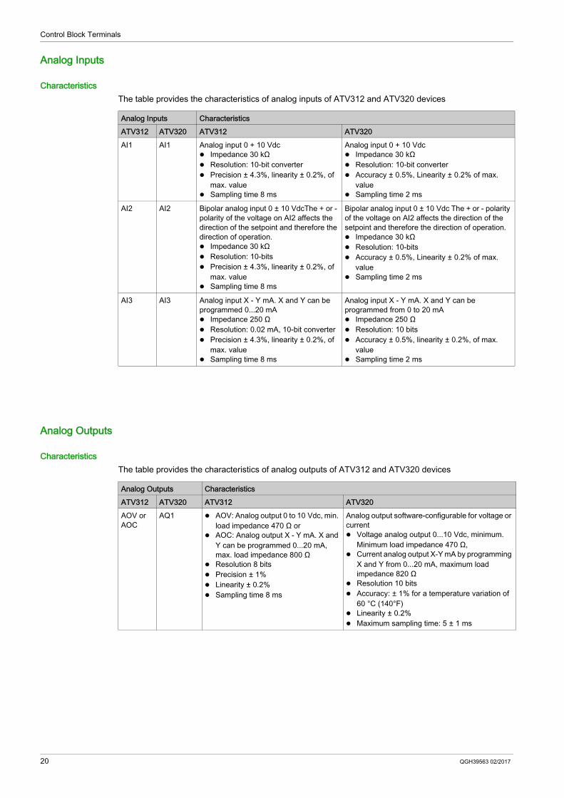
Analog input 0 + 10 Vdc Impedance 30 kΩ Resolution: 10-bit converter Accuracy ± 0.5%, Linearity ± 0.2% of max.
value Sampling time 2 ms
AI2 AI2 Bipolar analog input 0 ± 10 VdcThe + or - polarity of the voltage on AI2 affects the direction of the setpoint and therefore the direction of operation. Impedance 30 kΩ Resolution: 10-bits Precision ± 4.3%, linearity ± 0.2%, of
max. value Sampling time 8 ms
Bipolar analog input 0 ± 10 Vdc The + or - polarity of the voltage on AI2 affects the direction of the setpoint and therefore the direction of operation. Impedance 30 kΩ Resolution: 10-bits Accuracy ± 0.5%, Linearity ± 0.2% of max.
value Sampling time 2 ms
AI3 AI3 Analog input X - Y mA. X and Y can be programmed 0...20 mA Impedance 250 Ω Resolution: 0.02 mA, 10-bit converter Precision ± 4.3%, linearity ± 0.2%, of
max. value Sampling time 8 ms
Analog input X - Y mA. X and Y can be programmed from 0 to 20 mA Impedance 250 Ω Resolution: 10 bits Accuracy ± 0.5%, linearity ± 0.2%, of max.
value Sampling time 2 ms
Analog Outputs CharacteristicsATV312 ATV320 ATV312 ATV320AOV or AOC
AQ1 AOV: Analog output 0 to 10 Vdc, min. load impedance 470 Ω or
AOC: Analog output X - Y mA. X and Y can be programmed 0...20 mA, max. load impedance 800 Ω
Resolution 8 bits Precision ± 1% Linearity ± 0.2% Sampling time 8 ms
Analog output software-configurable for voltage or current Voltage analog output 0...10 Vdc, minimum.
Minimum load impedance 470 Ω, Current analog output X-Y mA by programming
X and Y from 0...20 mA, maximum load impedance 820 Ω
Resolution 10 bits Accuracy: ± 1% for a temperature variation of
60 °C (140°F) Linearity ± 0.2% Maximum sampling time: 5 ± 1 ms
Control Block Terminals
QGH39563 02/2017 21
Power Supplies
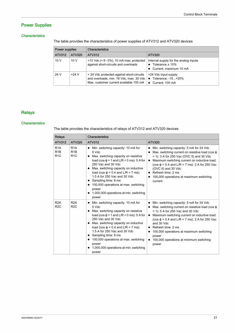
CharacteristicsThe table provides the characteristics of power supplies of ATV312 and ATV320 devices
Relays
CharacteristicsThe table provides the characteristics of relays of ATV312 and ATV320 devices
Power supplies CharacteristicsATV312 ATV320 ATV312 ATV32010 V 10 V +10 Vdc (+ 8 - 0%), 10 mA max, protected
against short-circuits and overloadsInternal supply for the analog inputs Tolerance ± 10% Current: maximum 10 mA
24 V +24 V + 24 Vdc protected against short-circuits and overloads, min. 19 Vdc, max. 30 VdcMax. customer current available 100 mA
+24 Vdc input supply Tolerance: -15...+20% Current: 100 mA
Jump Frequency 32PID Regulator 32Internal PID reference 32Preset PID Reference 33Sleep / Wake-Up 33Catch On the Fly 33Automatic Restart 33Multi-Motors / Multi-Configurations 34
Function Compatibilities
24 QGH39563 02/2017
Applicative Functions
IntroductionATV320 offers similar applicative functions compare to ATV312. ATV320 offers also additional functions like functional safety, ATV Logic, and so onFor more information about the ATV320 functions, refer to the ATV320 Programming Manual (NVE41295).
List of FunctionsNOTE: Some functions available on both products can have minor differences and cannot be converted; this will be detailed on next pages.The table provides the summary of the functions available in ATV312 and ATV320
WARNINGUNANTICIPATED EQUIPMENT OPERATIONDevice conversion function is used to apply the configuration from a drive product range to another drive product range. However, the values of certain parameters cannot be applied because the functional behaviors of the source drive and the target drive are different.The parameters whose values cannot be applied are kept to the factory settings. Consult the programming manual for the parameters that are kept to their factory settings and select
appropriate values for these parameters. Do not operate the product with unknown or unsuitable settings or data. Perform a comprehensive commissioning test.Failure to follow these instructions can result in death, serious injury, or equipment damage.
OverviewThis function is available in both ATV312 and ATV320 drivesIn factory settings, the reverse function [Reverse Assign] RRS is set to the [DI2] LI2 on both products.
Device ConversionConversion from an ATV312 configuration into ATV320 configuration is supported for this function.
Reverse Inhibition
OverviewThis function is available in both ATV312 and ATV320 drives but the parameters are not the sameOn ATV312, this function is set using the [Rotating direction] ROT? parameter.
On ATV320, this function is set using the [Reverse Disable] RIN? parameter.
Device ConversionConversion from an ATV312 configuration into ATV320 configuration is not supported for this function.For more information about Reverse Inhibition, refer to the ATV320 Programming Manual (NVE41295).
Speed Loop Parameters
OverviewThis function is available in both ATV312 and ATV320 drives but the parameters are not the sameThese parameters have an effect on the drives performances.
Device ConversionConversion from an ATV312 configuration into ATV320 configuration is not supported for this function.The parameters related to this function are set to factory setting values and needs to be adjusted depending on the application.For more information about Speed Loop Parameters, refer to the ATV320 Programming Manual (NVE41295).
OverviewThis function is available in both ATV312 and ATV320 drives but macro-configuration lists are not the same.On ATV312, there are 2 sets of macro configurations.On ATV320, there are 6 sets of macro configurations.
Device ConversionConversion from an ATV312 configuration into ATV320 configuration is not supported for this function.The parameters related to this function are set to factory setting values and needs to be adjusted depending on the application.For more information about macro-configuration, refer to the ATV320 Programming Manual (NVE41295).
I/O Multi-Assignments
OverviewThis function is available in both ATV312 and ATV320 drives.
Device ConversionConversion from an ATV312 configuration into ATV320 configuration is supported for this function with some limitation that is; if the digital output is used in combination with the brake sequence, conversion is not possible.The parameters related to this function are set to factory setting values and needs to be adjusted depending on the application.For more information about I/O Multi-Assignments, refer to the ATV320 Programming Manual (NVE41295).
2/3 Wires Control
OverviewThis function is available in both ATV312 and ATV320 drives.
Device ConversionConversion from an ATV312 configuration into ATV320 configuration is supported for this function.For more information about 2/3 Wires Control, refer to the ATV320 Programming Manual (NVE41295).
OverviewThis function is available in both ATV312 and ATV320 drives.
Device ConversionConversion from an ATV312 configuration into ATV320 configuration is supported for this function.For more information about Freewheel Stop, refer to the ATV320 Programming Manual (NVE41295).
Fast Stop
OverviewThis function is available in both ATV312 and ATV320 drives.
Device ConversionConversion from an ATV312 configuration into ATV320 configuration is supported for this function.For more information about Fast Stop, refer to the ATV320 Programming Manual (NVE41295).
Ramp Types
OverviewThis function is available in both ATV312 and ATV320 drives.Depending of the value of the parameter [Ramp Type] RPT, the values of [Acceleration] ACC, [Deceleration] DEC, [Acceleration 2] AC2 and [Deceleration 2] DE2 are converted: If [Ramp Type] RPT is set to [Linear] LIN, the parameters are converted without modification. If [Ramp Type] RPT is set to [S-Ramp] S, the parameters are converted following this formula: ACC
= ACC/1.4, DEC = DEC/1.4, AC2 = AC2/1.4, DE2 = DE2/1.4 If [Ramp Type] RPT is set to [U-Ramp] U, the parameters are converted following this formula: ACC
= ACC/1.5, DEC = DEC/1.5, AC2 = AC2/1.5, DE2 = DE2/1.5 If [Ramp Type] RPT is set to [Customized] CUS, the parameter are converted following this formula:
Device ConversionConversion from an ATV312 configuration into ATV320 configuration is supported for this function.For more information about Ramp Types, refer to the ATV320 Programming Manual (NVE41295).
OverviewThis function is available in both ATV312 and ATV320 drives.
Device ConversionConversion from an ATV312 configuration into ATV320 configuration is supported for this function.The parameters related to this function are set to factory setting values and needs to be adjusted depending on the application.For more information about Ramp Switching, refer to the ATV320 Programming Manual (NVE41295).
Ramp Auto-Adaptation
OverviewThis function is available in both ATV312 and ATV320 drives.
Device ConversionConversion from an ATV312 configuration into ATV320 configuration is supported for this function.For more information about Ramp Auto-Adaptation, refer to the ATV320 Programming Manual (NVE41295).
DC Injection Braking
OverviewThis function is available in both ATV312 and ATV320 drives.ATV320 offers additional parameters for this function.
Device ConversionConversion from an ATV312 configuration into ATV320 configuration is supported for this function.For more information about DC Injection Braking, refer to the ATV320 Programming Manual (NVE41295).
OverviewThis function is available in both ATV312 and ATV320 drives but configuration of this function is not the same.
Device ConversionConversion from an ATV312 configuration into ATV320 configuration is not supported for this function.For more information about Reference Switching, refer to the ATV320 Programming Manual (NVE41295).
Separate Mode (Command & Reference)
OverviewThis function is available in both ATV312 and ATV320 drives but configuration of this function is not the same.
Device ConversionConversion from an ATV312 configuration into ATV320 configuration is not supported for this function.The parameters related to this function are set to factory setting values and needs to be adjusted depending on the application.For more information about Separate Mode (Command & Reference), refer to the ATV320 Programming Manual (NVE41295).
Reference Operation
OverviewThis function is available in both ATV312 and ATV320 drives.ATV320 offers additional parameters for this function.
Device ConversionConversion from an ATV312 configuration into ATV320 configuration is supported for this function.For more information about Reference Operation, refer to the ATV320 Programming Manual (NVE41295).
OverviewThis function is available in both ATV312 and ATV320 drives.
Device ConversionConversion from an ATV312 configuration into ATV320 configuration is supported for this function.For more information about Jog, refer to the ATV320 Programming Manual (NVE41295).
Preset Speeds
OverviewThis function is available in both ATV312 and ATV320 drives.
Device ConversionConversion from an ATV312 configuration into ATV320 configuration is supported for this function.For more information about Preset Speeds, refer to the ATV320 Programming Manual (NVE41295).
Brake Control Sequence
OverviewThis function is available in both ATV312 and ATV320 drives but configuration of this function is not the same.
Device ConversionConversion from an ATV312 configuration into ATV320 configuration is not supported for this function.The parameters related to this function are set to factory setting values and needs to be adjusted depending on the application.For more information about Brake Control Sequence, refer to the ATV320 Programming Manual (NVE41295).
+/- Speed
OverviewThis function is available in both ATV312 and ATV320 drives.
Device ConversionConversion from an ATV312 configuration into ATV320 configuration is supported for this function.For more information about +/- Speed, refer to the ATV320 Programming Manual (NVE41295).
OverviewThis function is available in both ATV312 and ATV320 drives.
Device ConversionConversion from an ATV312 configuration into ATV320 configuration is supported for this function.
For more information about 2nd Current Limitation, refer to the ATV320 Programming Manual (NVE41295).
Jump Frequency
OverviewThis function is available in both ATV312 and ATV320 drives.ATV320 offers additional parameters for this function.
Device ConversionConversion from an ATV312 configuration into ATV320 configuration is supported for this function.For more information about Jump Frequency, refer to the ATV320 Programming Manual (NVE41295).
PID Regulator
OverviewThis function is available in both ATV312 and ATV320 drives.ATV312 offers a PI Regulator.ATV320 offers a PID Regulator.
Device ConversionConversion from an ATV312 configuration into ATV320 configuration is not supported for this function.The parameters related to this function are set to factory setting values and needs to be adjusted depending on the application.For more information about PID Regulator, refer to the ATV320 Programming Manual (NVE41295).
Internal PID reference
OverviewThis function is available in both ATV312 and ATV320 drives but configuration of this function is not the same.
Device ConversionConversion from an ATV312 configuration into ATV320 configuration is not supported for this function.The parameters related to this function are set to factory setting values and needs to be adjusted depending on the application.For more information about Internal PID reference, refer to the ATV320 Programming Manual (NVE41295).
OverviewThis function is available in both ATV312 and ATV320 drives but configuration of this function is not the same.
Device ConversionConversion from an ATV312 configuration into ATV320 configuration is not supported for this function.The parameters related to this function are set to factory setting values and needs to be adjusted depending on the application.For more information about Internal Preset PID Reference, refer to the ATV320 Programming Manual (NVE41295).
Sleep / Wake-Up
OverviewThis function is available in both ATV312 and ATV320 drives but configuration of this function is not the same.
Device ConversionConversion from an ATV312 configuration into ATV320 configuration is not supported for this function.The parameters related to this function are set to factory setting values and needs to be adjusted depending on the application.For more information about Sleep / Wake-Up, refer to the ATV320 Programming Manual (NVE41295).
Catch On the Fly
OverviewThis function is available in both ATV312 and ATV320 drives.
Device ConversionConversion from an ATV312 configuration into ATV320 configuration is supported for this function.For more information about Catch On the Fly, refer to the ATV320 Programming Manual (NVE41295).
Automatic Restart
OverviewThis function is available in both ATV312 and ATV320 drives.
Device ConversionConversion from an ATV312 configuration into ATV320 configuration is supported for this function.For more information about Automatic Restart, refer to the ATV320 Programming Manual (NVE41295).
OverviewThis function is available in both ATV312 and ATV320 drives but configuration of this function is not the same.
Device ConversionConversion from an ATV312 configuration into ATV320 configuration is not supported for this function.The parameters related to this function are set to factory setting values and needs to be adjusted depending on the application.For more information about Multi-Motors / Multi-Configurations, refer to the ATV320 Programming Manual (NVE41295).