129
NVE61069.01 www.schneider-electric.com Altivar Machine ATV340 NVE61069 11/2016 Altivar Machine ATV340 Variable Speed Drives Installation Manual 11/2016

Altivar Machine ATV340
NVE61069 11/2016
NVE
6106
9.01
www.schneider-electric.com
Altivar Machine ATV340Variable Speed Drives
Installation Manual11/2016

The information provided in this documentation contains general descriptions and/or technical character-istics of the performance of the products contained herein. This documentation is not intended as a substitute for and is not to be used for determining suitability or reliability of these products for specific user applications. It is the duty of any such user or integrator to perform the appropriate and complete risk analysis, evaluation and testing of the products with respect to the relevant specific application or use thereof. Neither Schneider Electric nor any of its affiliates or subsidiaries shall be responsible or liable for misuse of the information contained herein. If you have any suggestions for improvements or amendments or have found errors in this publication, please notify us. No part of this document may be reproduced in any form or by any means, electronic or mechanical, including photocopying, without express written permission of Schneider Electric.All pertinent state, regional, and local safety regulations must be observed when installing and using this product. For reasons of safety and to help ensure compliance with documented system data, only the manufacturer should perform repairs to components.When devices are used for applications with technical safety requirements, the relevant instructions must be followed. Failure to use Schneider Electric software or approved software with our hardware products may result in injury, harm, or improper operating results.Failure to observe this information can result in injury or equipment damage.© 2016 Schneider Electric. All Rights Reserved.
2 NVE61069 11/2016
Table of Contents
Safety Information. . . . . . . . . . . . . . . . . . . . . . . . . . . . . . . . . . . . . . . . . . . . 5About the Book . . . . . . . . . . . . . . . . . . . . . . . . . . . . . . . . . . . . . . . . . . . . . . 9
Chapter 1 Introduction . . . . . . . . . . . . . . . . . . . . . . . . . . . . . . . . . . . . . . . . . . . . . . . . . 11Verifying the Absence of Voltage . . . . . . . . . . . . . . . . . . . . . . . . . . . . . . . . . . . . . . . . . . . . . 12Drive Overview . . . . . . . . . . . . . . . . . . . . . . . . . . . . . . . . . . . . . . . . . . . . . . . . . . . . . . . . . . . 13Accessories and Options. . . . . . . . . . . . . . . . . . . . . . . . . . . . . . . . . . . . . . . . . . . . . . . . . . . . 16Display Terminals . . . . . . . . . . . . . . . . . . . . . . . . . . . . . . . . . . . . . . . . . . . . . . . . . . . . . . . . . 17Green Premium™ . . . . . . . . . . . . . . . . . . . . . . . . . . . . . . . . . . . . . . . . . . . . . . . . . . . . . . . . . 19Steps for Setting Up the Drive . . . . . . . . . . . . . . . . . . . . . . . . . . . . . . . . . . . . . . . . . . . . . . . . 20Preliminary Instructions . . . . . . . . . . . . . . . . . . . . . . . . . . . . . . . . . . . . . . . . . . . . . . . . . . . . . 21
Chapter 2 Technical Data . . . . . . . . . . . . . . . . . . . . . . . . . . . . . . . . . . . . . . . . . . . . . . 232.1 Mechanical Data . . . . . . . . . . . . . . . . . . . . . . . . . . . . . . . . . . . . . . . . . . . . . . . . . . . . . . . . . . 24
Environmental Conditions . . . . . . . . . . . . . . . . . . . . . . . . . . . . . . . . . . . . . . . . . . . . . . . . . . . 25Dimensions and Weights. . . . . . . . . . . . . . . . . . . . . . . . . . . . . . . . . . . . . . . . . . . . . . . . . . . . 27
2.2 Electrical Data . . . . . . . . . . . . . . . . . . . . . . . . . . . . . . . . . . . . . . . . . . . . . . . . . . . . . . . . . . . . 31Drive Ratings in Heavy Duty . . . . . . . . . . . . . . . . . . . . . . . . . . . . . . . . . . . . . . . . . . . . . . . . . 32Drive Ratings in Normal Duty . . . . . . . . . . . . . . . . . . . . . . . . . . . . . . . . . . . . . . . . . . . . . . . . 34Braking Resistors . . . . . . . . . . . . . . . . . . . . . . . . . . . . . . . . . . . . . . . . . . . . . . . . . . . . . . . . . 36
Chapter 3 Drive Mounting . . . . . . . . . . . . . . . . . . . . . . . . . . . . . . . . . . . . . . . . . . . . . . 37Mounting Conditions . . . . . . . . . . . . . . . . . . . . . . . . . . . . . . . . . . . . . . . . . . . . . . . . . . . . . . . 38Derating Curves. . . . . . . . . . . . . . . . . . . . . . . . . . . . . . . . . . . . . . . . . . . . . . . . . . . . . . . . . . . 43Mounting Procedures . . . . . . . . . . . . . . . . . . . . . . . . . . . . . . . . . . . . . . . . . . . . . . . . . . . . . . 50
Chapter 4 Drive wiring . . . . . . . . . . . . . . . . . . . . . . . . . . . . . . . . . . . . . . . . . . . . . . . . . 514.1 General Wiring Information . . . . . . . . . . . . . . . . . . . . . . . . . . . . . . . . . . . . . . . . . . . . . . . . . . 52
Wiring Instructions . . . . . . . . . . . . . . . . . . . . . . . . . . . . . . . . . . . . . . . . . . . . . . . . . . . . . . . . . 53Cable Length Instructions . . . . . . . . . . . . . . . . . . . . . . . . . . . . . . . . . . . . . . . . . . . . . . . . . . . 56Electromagnetic Compatibility . . . . . . . . . . . . . . . . . . . . . . . . . . . . . . . . . . . . . . . . . . . . . . . . 57
4.2 General Wiring Diagrams . . . . . . . . . . . . . . . . . . . . . . . . . . . . . . . . . . . . . . . . . . . . . . . . . . . 59Wiring Diagrams for Frame Sizes 1...3: ATV340U07N4•...D22N4•. . . . . . . . . . . . . . . . . . . . 60Wiring Diagrams for Frame Sizes 4 and 5: ATV340D30N4E...D75N4E . . . . . . . . . . . . . . . . 63
4.3 Built-in EMC Filter . . . . . . . . . . . . . . . . . . . . . . . . . . . . . . . . . . . . . . . . . . . . . . . . . . . . . . . . . 65Operation on an IT System . . . . . . . . . . . . . . . . . . . . . . . . . . . . . . . . . . . . . . . . . . . . . . . . . . 66Disconnecting the Built-in EMC Filter . . . . . . . . . . . . . . . . . . . . . . . . . . . . . . . . . . . . . . . . . . 66
4.4 Power Part . . . . . . . . . . . . . . . . . . . . . . . . . . . . . . . . . . . . . . . . . . . . . . . . . . . . . . . . . . . . . . . 69Wiring the Power Part . . . . . . . . . . . . . . . . . . . . . . . . . . . . . . . . . . . . . . . . . . . . . . . . . . . . . . 70Characteristics of the Power Part Terminals . . . . . . . . . . . . . . . . . . . . . . . . . . . . . . . . . . . . . 76
4.5 Control Part . . . . . . . . . . . . . . . . . . . . . . . . . . . . . . . . . . . . . . . . . . . . . . . . . . . . . . . . . . . . . . 79Arrangement and Characteristics of Control Block Terminals, Communication and I/O Ports 80Control Terminals Electrical Data for Frame Sizes 1...3 . . . . . . . . . . . . . . . . . . . . . . . . . . . . 83Control Terminals Electrical data for Frame Sizes 4 and 5 . . . . . . . . . . . . . . . . . . . . . . . . . . 93Control Wires Cable Path on Frame Sizes 4 and 5. . . . . . . . . . . . . . . . . . . . . . . . . . . . . . . . 96Product LEDs . . . . . . . . . . . . . . . . . . . . . . . . . . . . . . . . . . . . . . . . . . . . . . . . . . . . . . . . . . . . 100
4.6 SK EXT SRC Switch Configuration . . . . . . . . . . . . . . . . . . . . . . . . . . . . . . . . . . . . . . . . . . . . 103SK-EXT-SRC Switch Configuration on Frame Sizes 1...3: ATV340U07N4•...D22N4• . . . . . 104SK-EXT-SRC Switch SW1 Configuration on Frame Sizes 4 and 5: ATV340D30N4E...D75N4E . . . . . . . . . . . . . . . . . . . . . . . . . . . . . . . . . . . . . . . . . . . . . . . . . . 105
4.7 PTO - DQ Switch (SW2) Configuration . . . . . . . . . . . . . . . . . . . . . . . . . . . . . . . . . . . . . . . . . 106PTO, Pulse Train Output Configuration on Frame Sizes 4 and 5 . . . . . . . . . . . . . . . . . . . . . 107Digital Output Configuration on Frame Sizes 4 and 5 . . . . . . . . . . . . . . . . . . . . . . . . . . . . . . 109
NVE61069 11/2016 3
4.8 Safe Torque Off STO Function . . . . . . . . . . . . . . . . . . . . . . . . . . . . . . . . . . . . . . . . . . . . . . . 111STO Safe Torque Off Wiring Diagram for Frame Sizes 1...3 . . . . . . . . . . . . . . . . . . . . . . . . . 112STO Safe Torque Off Wiring Diagram for Frame Sizes 4 and 5 . . . . . . . . . . . . . . . . . . . . . . 113
4.9 Digital Inputs Wiring . . . . . . . . . . . . . . . . . . . . . . . . . . . . . . . . . . . . . . . . . . . . . . . . . . . . . . . . 114Digital Inputs Wiring on Frame Sizes 1...3 . . . . . . . . . . . . . . . . . . . . . . . . . . . . . . . . . . . . . . . 115Digital Inputs Wiring on Frame Sizes 4 and 5 . . . . . . . . . . . . . . . . . . . . . . . . . . . . . . . . . . . . 117
4.10 Digital Outputs Wiring . . . . . . . . . . . . . . . . . . . . . . . . . . . . . . . . . . . . . . . . . . . . . . . . . . . . . . 118Digital Outputs Wiring on Frame sizes 1...3. . . . . . . . . . . . . . . . . . . . . . . . . . . . . . . . . . . . . . 119Digital Outputs Wiring on Frame sizes 4 and 5 . . . . . . . . . . . . . . . . . . . . . . . . . . . . . . . . . . . 119
4.11 Relay Contacts Wiring . . . . . . . . . . . . . . . . . . . . . . . . . . . . . . . . . . . . . . . . . . . . . . . . . . . . . . 120Relay Contacts Wiring on Frame Sizes 1...5 . . . . . . . . . . . . . . . . . . . . . . . . . . . . . . . . . . . . . 120
Chapter 5 Checking Installation . . . . . . . . . . . . . . . . . . . . . . . . . . . . . . . . . . . . . . . . . . 123Before Switching On . . . . . . . . . . . . . . . . . . . . . . . . . . . . . . . . . . . . . . . . . . . . . . . . . . . . . . . 123
Chapter 6 Maintenance. . . . . . . . . . . . . . . . . . . . . . . . . . . . . . . . . . . . . . . . . . . . . . . . . 125Scheduled servicing . . . . . . . . . . . . . . . . . . . . . . . . . . . . . . . . . . . . . . . . . . . . . . . . . . . . . . . . 125
Glossary . . . . . . . . . . . . . . . . . . . . . . . . . . . . . . . . . . . . . . . . . . . . . . . . . . . . . . 127
4 NVE61069 11/2016

Safety Information
Important Information
NOTICERead these instructions carefully, and look at the equipment to become familiar with the device before trying to install, operate, service, or maintain it. The following special messages may appear throughout this documentation or on the equipment to warn of potential hazards or to call attention to information that clarifies or simplifies a procedure.
PLEASE NOTEElectrical equipment should be installed, operated, serviced, and maintained only by qualified personnel. No responsibility is assumed by Schneider Electric for any consequences arising out of the use of this material.A qualified person is one who has skills and knowledge related to the construction and operation of electrical equipment and its installation, and has received safety training to recognize and avoid the hazards involved.
Qualification Of PersonnelOnly appropriately trained persons who are familiar with and understand the contents of this manual and all other pertinent product documentation are authorized to work on and with this product. In addition, these persons must have received safety training to recognize and avoid hazards involved. These persons must have sufficient technical training, knowledge and experience and be able to foresee and detect potential hazards that may be caused by using the product, by changing the settings and by the mechanical, electrical and electronic equipment of the entire system in which the product is used. All persons working on and with the product must be fully familiar with all applicable standards, directives, and accident prevention regulations when performing such work.
NVE61069 11/2016 5
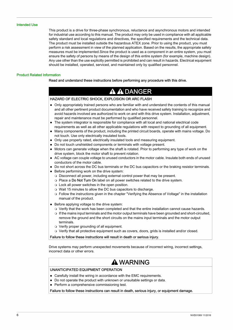
Intended UseThis product is a drive for three-phase synchronous, reluctance and asynchronous motors and intended for industrial use according to this manual. The product may only be used in compliance with all applicable safety standard and local regulations and directives, the specified requirements and the technical data. The product must be installed outside the hazardous ATEX zone. Prior to using the product, you must perform a risk assessment in view of the planned application. Based on the results, the appropriate safety measures must be implemented.Since the product is used as a component in an entire system, you must ensure the safety of persons by means of the design of this entire system (for example, machine design). Any use other than the use explicitly permitted is prohibited and can result in hazards. Electrical equipment should be installed, operated, serviced, and maintained only by qualified personnel.
Product Related InformationRead and understand these instructions before performing any procedure with this drive.
Drive systems may perform unexpected movements because of incorrect wiring, incorrect settings, incorrect data or other errors.
DANGERHAZARD OF ELECTRIC SHOCK, EXPLOSION OR ARC FLASH Only appropriately trained persons who are familiar with and understand the contents of this manual
and all other pertinent product documentation and who have received safety training to recognize and avoid hazards involved are authorized to work on and with this drive system. Installation, adjustment, repair and maintenance must be performed by qualified personnel.
The system integrator is responsible for compliance with all local and national electrical code requirements as well as all other applicable regulations with respect to grounding of all equipment.
Many components of the product, including the printed circuit boards, operate with mains voltage. Do not touch. Use only electrically insulated tools.
Only use properly rated, electrically insulated tools and measuring equipment. Do not touch unshielded components or terminals with voltage present. Motors can generate voltage when the shaft is rotated. Prior to performing any type of work on the
drive system, block the motor shaft to prevent rotation. AC voltage can couple voltage to unused conductors in the motor cable. Insulate both ends of unused
conductors of the motor cable. Do not short across the DC bus terminals or the DC bus capacitors or the braking resistor terminals. Before performing work on the drive system: Disconnect all power, including external control power that may be present. Place a Do Not Turn On label on all power switches related to the drive system. Lock all power switches in the open position. Wait 15 minutes to allow the DC bus capacitors to discharge. Follow the instructions given in the chapter "Verifying the Absence of Voltage" in the installation
manual of the product. Before applying voltage to the drive system: Verify that the work has been completed and that the entire installation cannot cause hazards. If the mains input terminals and the motor output terminals have been grounded and short-circuited,
remove the ground and the short circuits on the mains input terminals and the motor output terminals.
Verify proper grounding of all equipment. Verify that all protective equipment such as covers, doors, grids is installed and/or closed.
Failure to follow these instructions will result in death or serious injury.
WARNINGUNANTICIPATED EQUIPMENT OPERATION Carefully install the wiring in accordance with the EMC requirements. Do not operate the product with unknown or unsuitable settings or data. Perform a comprehensive commissioning test.Failure to follow these instructions can result in death, serious injury, or equipment damage.
6 NVE61069 11/2016
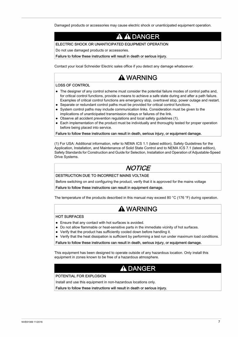
Damaged products or accessories may cause electric shock or unanticipated equipment operation.
Contact your local Schneider Electric sales office if you detect any damage whatsoever.
(1) For USA: Additional information, refer to NEMA ICS 1.1 (latest edition), Safety Guidelines for the Application, Installation, and Maintenance of Solid State Control and to NEMA ICS 7.1 (latest edition), Safety Standards for Construction and Guide for Selection, Installation and Operation of Adjustable-Speed Drive Systems.
The temperature of the products described in this manual may exceed 80 °C (176 °F) during operation.
This equipment has been designed to operate outside of any hazardous location. Only install this equipment in zones known to be free of a hazardous atmosphere.
DANGERELECTRIC SHOCK OR UNANTICIPATED EQUIPMENT OPERATIONDo not use damaged products or accessories.Failure to follow these instructions will result in death or serious injury.
WARNINGLOSS OF CONTROL The designer of any control scheme must consider the potential failure modes of control paths and,
for critical control functions, provide a means to achieve a safe state during and after a path failure. Examples of critical control functions are emergency stop, overtravel stop, power outage and restart.
Separate or redundant control paths must be provided for critical control functions. System control paths may include communication links. Consideration must be given to the
implications of unanticipated transmission delays or failures of the link. Observe all accident prevention regulations and local safety guidelines (1). Each implementation of the product must be individually and thoroughly tested for proper operation
before being placed into service.Failure to follow these instructions can result in death, serious injury, or equipment damage.
NOTICEDESTRUCTION DUE TO INCORRECT MAINS VOLTAGEBefore switching on and configuring the product, verify that it is approved for the mains voltageFailure to follow these instructions can result in equipment damage.
WARNINGHOT SURFACES Ensure that any contact with hot surfaces is avoided. Do not allow flammable or heat-sensitive parts in the immediate vicinity of hot surfaces. Verify that the product has sufficiently cooled down before handling it. Verify that the heat dissipation is sufficient by performing a test run under maximum load conditions.Failure to follow these instructions can result in death, serious injury, or equipment damage.
DANGERPOTENTIAL FOR EXPLOSIONInstall and use this equipment in non-hazardous locations only.Failure to follow these instructions will result in death or serious injury.
NVE61069 11/2016 7

8 NVE61069 11/2016
About the Book
At a Glance
Document ScopeThe purpose of this document is: to give you mechanical and electrical information related to the Altivar 340 drive, to show you how to install and wire this drive.
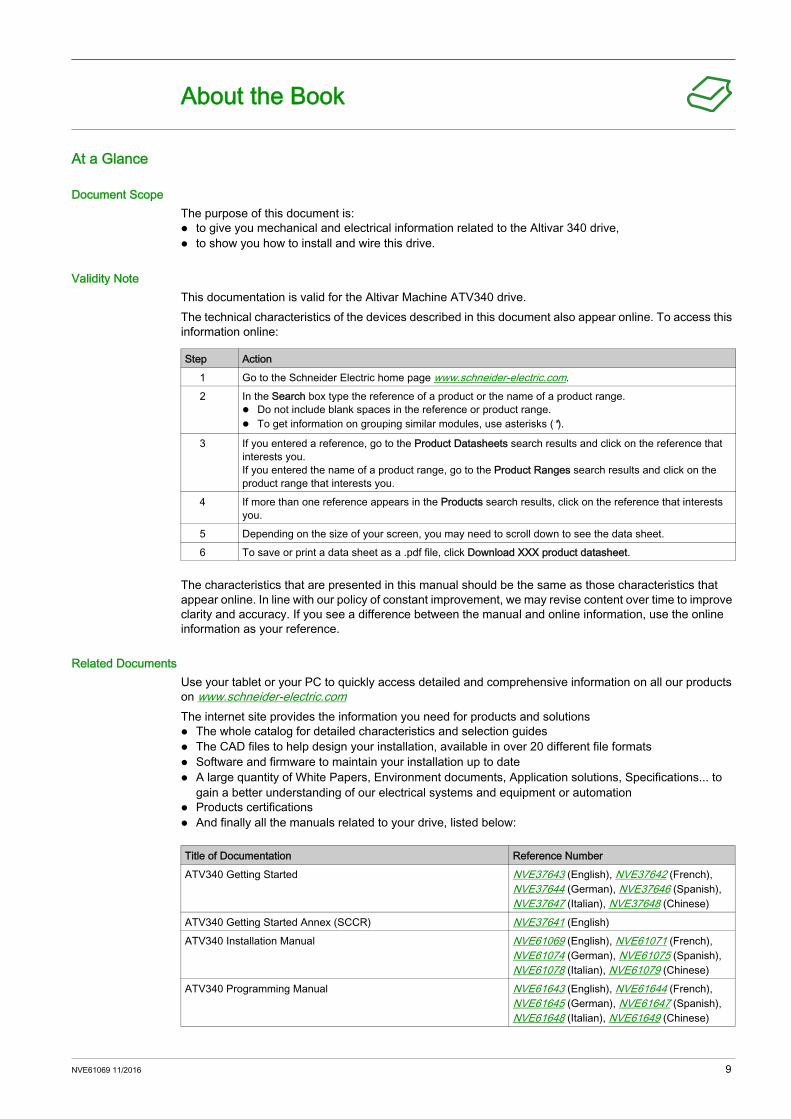
Validity NoteThis documentation is valid for the Altivar Machine ATV340 drive.The technical characteristics of the devices described in this document also appear online. To access this information online:
The characteristics that are presented in this manual should be the same as those characteristics that appear online. In line with our policy of constant improvement, we may revise content over time to improve clarity and accuracy. If you see a difference between the manual and online information, use the online information as your reference.
Related DocumentsUse your tablet or your PC to quickly access detailed and comprehensive information on all our products on www.schneider-electric.comThe internet site provides the information you need for products and solutions The whole catalog for detailed characteristics and selection guides The CAD files to help design your installation, available in over 20 different file formats Software and firmware to maintain your installation up to date A large quantity of White Papers, Environment documents, Application solutions, Specifications... to
gain a better understanding of our electrical systems and equipment or automation Products certifications And finally all the manuals related to your drive, listed below:
Step Action1 Go to the Schneider Electric home page www.schneider-electric.com.2 In the Search box type the reference of a product or the name of a product range.
Do not include blank spaces in the reference or product range. To get information on grouping similar modules, use asterisks (*).
3 If you entered a reference, go to the Product Datasheets search results and click on the reference that interests you.If you entered the name of a product range, go to the Product Ranges search results and click on the product range that interests you.
4 If more than one reference appears in the Products search results, click on the reference that interests you.
5 Depending on the size of your screen, you may need to scroll down to see the data sheet.6 To save or print a data sheet as a .pdf file, click Download XXX product datasheet.
Title of Documentation Reference NumberATV340 Getting Started NVE37643 (English), NVE37642 (French),
NVE37644 (German), NVE37646 (Spanish), NVE37647 (Italian), NVE37648 (Chinese)
ATV340 Getting Started Annex (SCCR) NVE37641 (English)ATV340 Installation Manual NVE61069 (English), NVE61071 (French),
NVE61074 (German), NVE61075 (Spanish), NVE61078 (Italian), NVE61079 (Chinese)
ATV340 Programming Manual NVE61643 (English), NVE61644 (French), NVE61645 (German), NVE61647 (Spanish), NVE61648 (Italian), NVE61649 (Chinese)
NVE61069 11/2016 9
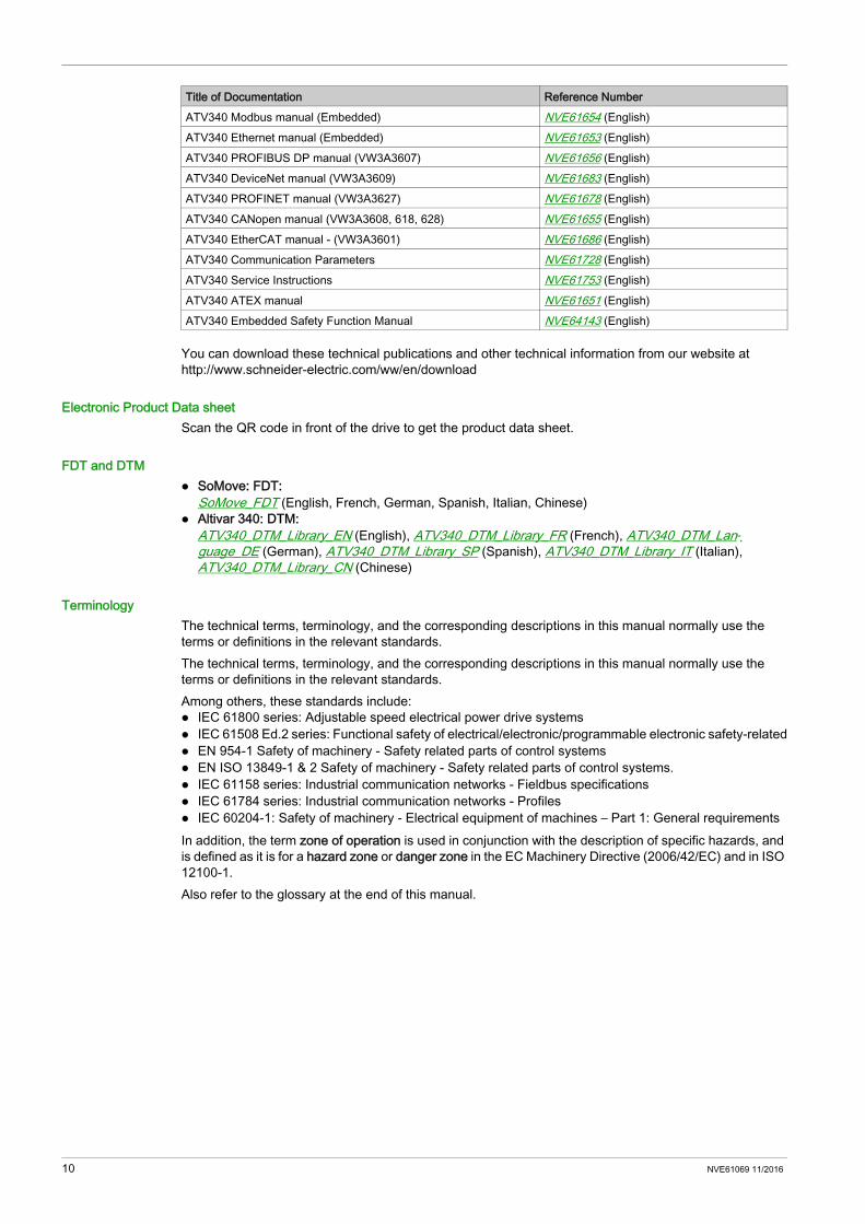
You can download these technical publications and other technical information from our website at http://www.schneider-electric.com/ww/en/download
Electronic Product Data sheetScan the QR code in front of the drive to get the product data sheet.
FDT and DTM SoMove: FDT:
SoMove_FDT (English, French, German, Spanish, Italian, Chinese) Altivar 340: DTM:
ATV340_DTM_Library_EN (English), ATV340_DTM_Library_FR (French), ATV340_DTM_Lan-guage_DE (German), ATV340_DTM_Library_SP (Spanish), ATV340_DTM_Library_IT (Italian), ATV340_DTM_Library_CN (Chinese)
TerminologyThe technical terms, terminology, and the corresponding descriptions in this manual normally use the terms or definitions in the relevant standards.The technical terms, terminology, and the corresponding descriptions in this manual normally use the terms or definitions in the relevant standards.Among others, these standards include: IEC 61800 series: Adjustable speed electrical power drive systems IEC 61508 Ed.2 series: Functional safety of electrical/electronic/programmable electronic safety-related EN 954-1 Safety of machinery - Safety related parts of control systems EN ISO 13849-1 & 2 Safety of machinery - Safety related parts of control systems. IEC 61158 series: Industrial communication networks - Fieldbus specifications IEC 61784 series: Industrial communication networks - Profiles IEC 60204-1: Safety of machinery - Electrical equipment of machines – Part 1: General requirementsIn addition, the term zone of operation is used in conjunction with the description of specific hazards, and is defined as it is for a hazard zone or danger zone in the EC Machinery Directive (2006/42/EC) and in ISO 12100-1.Also refer to the glossary at the end of this manual.
ATV340 Modbus manual (Embedded) NVE61654 (English)ATV340 Ethernet manual (Embedded) NVE61653 (English)ATV340 PROFIBUS DP manual (VW3A3607) NVE61656 (English)ATV340 DeviceNet manual (VW3A3609) NVE61683 (English)ATV340 PROFINET manual (VW3A3627) NVE61678 (English)ATV340 CANopen manual (VW3A3608, 618, 628) NVE61655 (English)ATV340 EtherCAT manual - (VW3A3601) NVE61686 (English)ATV340 Communication Parameters NVE61728 (English)ATV340 Service Instructions NVE61753 (English)ATV340 ATEX manual NVE61651 (English)ATV340 Embedded Safety Function Manual NVE64143 (English)
Title of Documentation Reference Number
10 NVE61069 11/2016

Altivar Machine ATV340
NVE61069 11/2016
Introduction
Chapter 1Introduction
What Is in This Chapter?This chapter contains the following topics:
Topic PageVerifying the Absence of Voltage 12Drive Overview 13Accessories and Options 16Display Terminals 17Green Premium™ 19Steps for Setting Up the Drive 20Preliminary Instructions 21
NVE61069 11/2016 11

Verifying the Absence of Voltage
InstructionsThe DC bus voltage level is determined by measuring the voltage between the DC bus terminals PA/+ and PC/-. The location of the DC bus terminals depends on the drive model.Identify your drive model by referring to the nameplate of the drive. Then, refer to the chapter "Wiring the Power Part" (see page 70) for the location of the DC bus terminals PA/+ and PC/-.
ProcedurePerform the following actions to verify the absence of voltage
DANGERHAZARD OF ELECTRIC SHOCK, EXPLOSION OR ARC FLASH Only appropriately trained persons who are familiar with and understand the contents of this manual
and all other pertinent product documentation and who have received safety training to recognize and avoid hazards involved are authorized to work on and with this drive system. Installation, adjustment, repair and maintenance must be performed by qualified personnel.
The system integrator is responsible for compliance with all local and national electrical code requirements as well as all other applicable regulations with respect to grounding of all equipment.
Many components of the product, including the printed circuit boards, operate with mains voltage. Do not touch. Use only electrically insulated tools.
Only use properly rated, electrically insulated tools and measuring equipment. Do not touch unshielded components or terminals with voltage present. Motors can generate voltage when the shaft is rotated. Prior to performing any type of work on the
drive system, block the motor shaft to prevent rotation. AC voltage can couple voltage to unused conductors in the motor cable. Insulate both ends of unused
conductors of the motor cable. Do not short across the DC bus terminals or the DC bus capacitors or the braking resistor terminals. Before performing work on the drive system: Disconnect all power, including external control power that may be present. Place a Do Not Turn On label on all power switches related to the drive system. Lock all power switches in the open position. Wait 15 minutes to allow the DC bus capacitors to discharge. Follow the instructions given in the chapter "Verifying the Absence of Voltage" in the installation
manual of the product. Before applying voltage to the drive system: Verify that the work has been completed and that the entire installation cannot cause hazards. If the mains input terminals and the motor output terminals have been grounded and short-circuited,
remove the ground and the short circuits on the mains input terminals and the motor output terminals.
Verify proper grounding of all equipment. Verify that all protective equipment such as covers, doors, grids is installed and/or closed.
Failure to follow these instructions will result in death or serious injury.
Step Action1 Measure the voltage on the DC bus between the DC bus terminals (PA/+ and PC/-) using a properly rated
voltmeter to verify that the voltage is less than 42 Vdc2 If the DC bus capacitors do not discharge properly, contact your local Schneider Electric representative.
Do not repair or operate the product.3 Verify that no other voltage is present in the drive system.
12 NVE61069 11/2016
Drive Overview
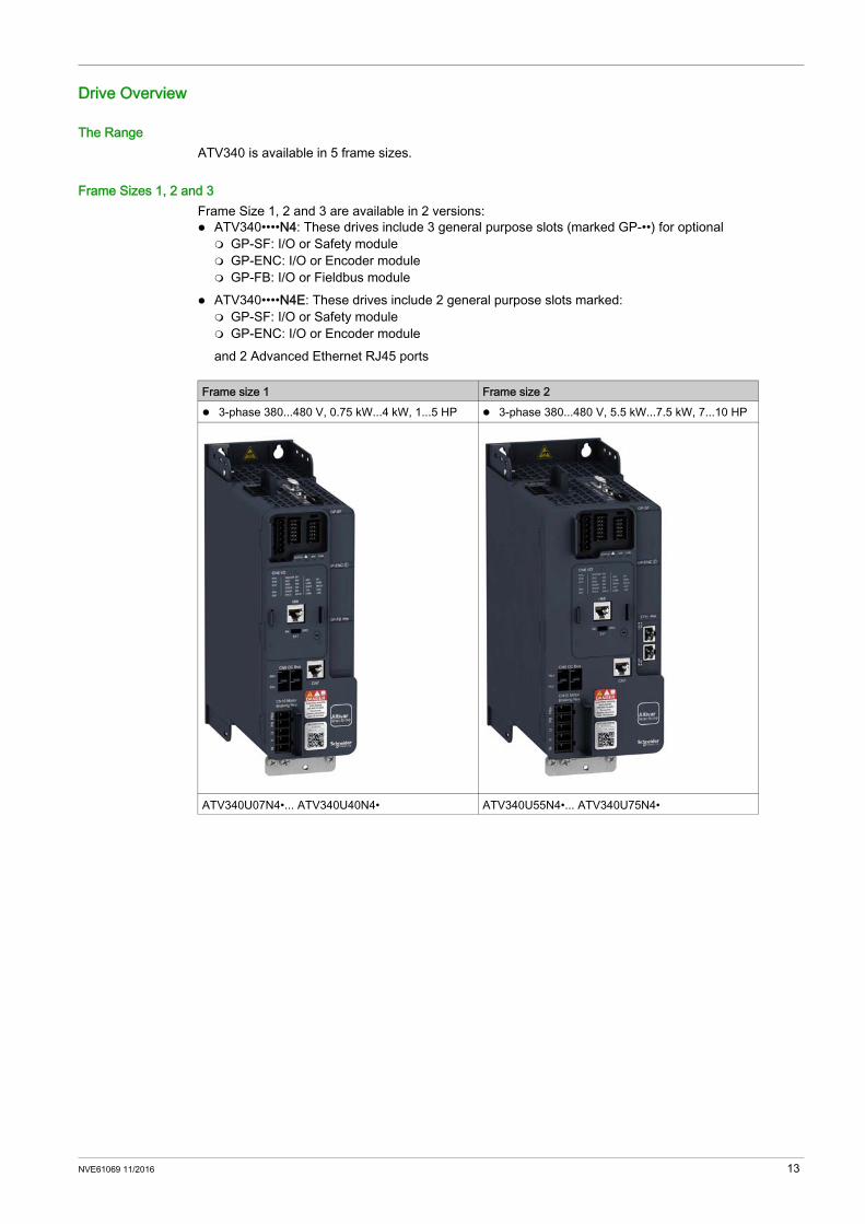
The RangeATV340 is available in 5 frame sizes.
Frame Sizes 1, 2 and 3Frame Size 1, 2 and 3 are available in 2 versions: ATV340••••N4: These drives include 3 general purpose slots (marked GP-••) for optional GP-SF: I/O or Safety module GP-ENC: I/O or Encoder module GP-FB: I/O or Fieldbus module
ATV340••••N4E: These drives include 2 general purpose slots marked: GP-SF: I/O or Safety module GP-ENC: I/O or Encoder moduleand 2 Advanced Ethernet RJ45 ports
Frame size 1 Frame size 2 3-phase 380...480 V, 0.75 kW...4 kW, 1...5 HP 3-phase 380...480 V, 5.5 kW...7.5 kW, 7...10 HP
ATV340U07N4•... ATV340U40N4• ATV340U55N4•... ATV340U75N4•
NVE61069 11/2016 13

Frame Sizes 4 and 5 are available in a single versionThese drives include: 2 slots for optional module: Slot A: for general purpose I/O or Fieldbus option Slot B: for general purpose I/O or Encoder option Slot C: for accessory GP I/O or Safety option using the option module adapter accessory
2 Advanced Ethernet RJ45 ports
Frame size 3 3-phase 380...480 V, 11 kW...22 kW, 15...30 HP
ATV340D11N4•... ATV340D22N4•
Frame size 4 Frame size 5 3-phase 380...480 V, 30 kW...37 kW, 40...50 HP 3-phase 380...480 V, 45 kW...75 kW, 60...100 HP
ATV340D30N4E... ATV340D37N4E ATV340D45N4E... ATV340D75N4E
14 NVE61069 11/2016
Catalog Number Description
NOTE: see the catalog for possible combinations.
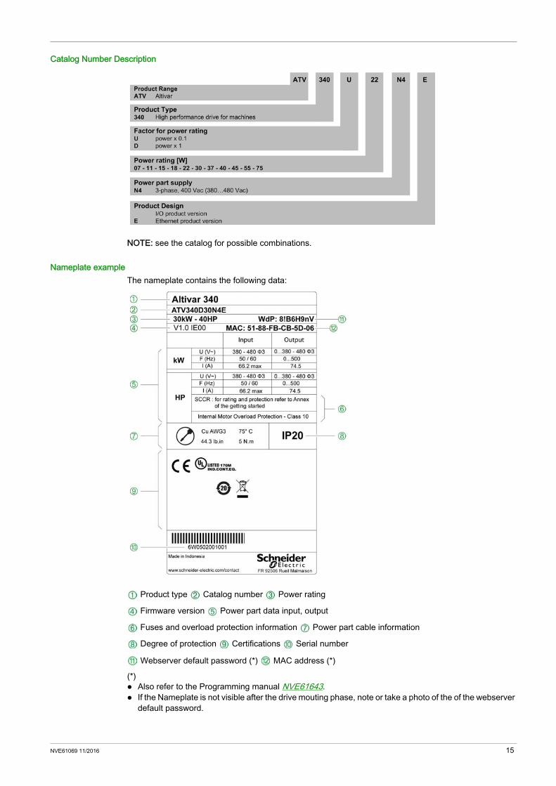
Nameplate exampleThe nameplate contains the following data:
Product type Catalog number Power rating
Firmware version Power part data input, output
Fuses and overload protection information Power part cable information
Degree of protection Certifications Serial number
Webserver default password (*) MAC address (*)
(*) Also refer to the Programming manual NVE61643. If the Nameplate is not visible after the drive mouting phase, note or take a photo of the of the webserver
default password.
NVE61069 11/2016 15

Accessories and Options
IntroductionThe Altivar Machine ATV340 drives are designed to take numerous accessories and options to increase their functionality. For a detailed description and catalog numbers, refer to the Catalog on www.schneider-electric.comAll accessories and options come with an instruction sheet to help installation and commissioning. Therefore you will only find here a short product description.
AccessoriesDrive Fan replacement kit EMC kits Connector kits Control cablesDisplay terminals Plain Text Display Terminal (VW3A1113) Graphic Display Terminal (VW3A1111) with a cable Remote mounting kit for mounting on enclosure door Multidrop connection accessories for connecting several drives to the RJ45 terminal portDrive mounting kits Flush-mounting kit (see page 39) for separate air flowModbus Communication tools Wifi dongle Bluetooth dongle USB to Modbus adapter
OptionsEncoder interface modules Resolver encoder interface module Digital interface encoder module 5/12 V Analog interface encoder moduleSafety functions moduleAdditional module supportI/O extension modules Digital and analog I/O module Relay output moduleCommunication modules CANopen daisy chain CANopen SUB-D CANopen screw terminal block PROFINET PROFIBUS DP V1 DeviceNet EtherCATBraking resistorsMains ChokesEMC filters
16 NVE61069 11/2016
Display Terminals
IntroductionThe drive is compatible with the Plain Text Display Terminal (VW3A1113) or with the Graphic Display Terminal (VW3A1111). These display terminals can be ordered separately.NOTE: In this manual, the term Display Terminal is used when it concerns both display terminals.
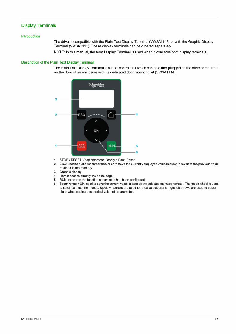
Description of the Plain Text Display TerminalThe Plain Text Display Terminal is a local control unit which can be either plugged on the drive or mounted on the door of an enclosure with its dedicated door mounting kit (VW3A1114).
1 STOP / RESET: Stop command / apply a Fault Reset.2 ESC: used to quit a menu/parameter or remove the currently displayed value in order to revert to the previous value
retained in the memory3 Graphic display.4 Home: access directly the home page.5 RUN: executes the function assuming it has been configured.6 Touch wheel / OK: used to save the current value or access the selected menu/parameter. The touch wheel is used
to scroll fast into the menus. Up/down arrows are used for precise selections, right/left arrows are used to select digits when setting a numerical value of a parameter.
NVE61069 11/2016 17
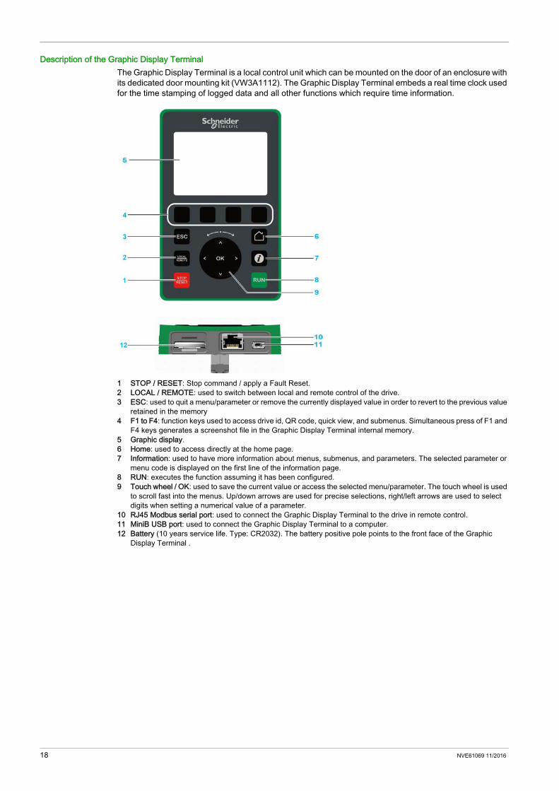
Description of the Graphic Display TerminalThe Graphic Display Terminal is a local control unit which can be mounted on the door of an enclosure with its dedicated door mounting kit (VW3A1112). The Graphic Display Terminal embeds a real time clock used for the time stamping of logged data and all other functions which require time information.
1 STOP / RESET: Stop command / apply a Fault Reset.2 LOCAL / REMOTE: used to switch between local and remote control of the drive.3 ESC: used to quit a menu/parameter or remove the currently displayed value in order to revert to the previous value
retained in the memory4 F1 to F4: function keys used to access drive id, QR code, quick view, and submenus. Simultaneous press of F1 and
F4 keys generates a screenshot file in the Graphic Display Terminal internal memory.5 Graphic display.6 Home: used to access directly at the home page.7 Information: used to have more information about menus, submenus, and parameters. The selected parameter or
menu code is displayed on the first line of the information page.8 RUN: executes the function assuming it has been configured.9 Touch wheel / OK: used to save the current value or access the selected menu/parameter. The touch wheel is used
to scroll fast into the menus. Up/down arrows are used for precise selections, right/left arrows are used to select digits when setting a numerical value of a parameter.
10 RJ45 Modbus serial port: used to connect the Graphic Display Terminal to the drive in remote control.11 MiniB USB port: used to connect the Graphic Display Terminal to a computer.12 Battery (10 years service life. Type: CR2032). The battery positive pole points to the front face of the Graphic
Display Terminal .
18 NVE61069 11/2016

Green Premium™
DescriptionInformation on the environmental impact of products, their resource efficiency, and end-of-life instructions.
Easy access to information: "Check Your Product"Certificates and relevant product information available at the address:www.schneider-electric.com/green-premiumYou can download RoHS and REACh compliance declarations, Product Environmental Profiles (PEP) and End-of-Life instructions (EoLi).
NVE61069 11/2016 19

Steps for Setting Up the Drive
Procedure
20 NVE61069 11/2016

Preliminary Instructions
Handling and Storage
To help protect the drive before installation, handle and store the device in its packaging. Ensure that the ambient conditions are acceptable.
Handling the DriveThe drives of frame sizes 1, 2 and 3 can be removed from their packaging and installed without a handling device.The drives of frame sizes 4 and 5 require a handling device; for this reason, these drives include lifting lugs.
Check the Delivery of the DriveDamaged products or accessories may cause electric shock or unanticipated equipment operation.
Contact your local Schneider Electric sales office if you detect any damage whatsoever.
WARNINGDANGEROUS HANDLING Do not handle a damaged packaging. Follow the handling instructions. Open and handle the packaging with care.Failure to follow these instructions can result in death, serious injury, or equipment damage.
DANGERELECTRIC SHOCK OR UNANTICIPATED EQUIPMENT OPERATIONDo not use damaged products or accessories.Failure to follow these instructions will result in death or serious injury.
Step Action1 Remove the drive from the packaging and verify that it has not been damaged2 Verify that the catalog number printed on the nameplate corresponds to the purchase order.
NVE61069 11/2016 21

22 NVE61069 11/2016

Altivar Machine ATV340
NVE61069 11/2016
Technical Data
Chapter 2Technical Data
What Is in This Chapter?This chapter contains the following sections:
Section Topic Page2.1 Mechanical Data 242.2 Electrical Data 31
NVE61069 11/2016 23

Mechanical Data
Section 2.1Mechanical Data
What Is in This Section?This section contains the following topics:
Topic PageEnvironmental Conditions 25Dimensions and Weights 27
24 NVE61069 11/2016

Environmental Conditions
Withstand to harsh environments Storage short time and transportation: 2C1, conforming to IEC/EN 60721-3-2 Storage long time: 1C1, Conforming to IEC/EN 60721-3-1 Chemical class: 3C3, conforming to IEC/EN 60721-3-3 Mechanical class: 3S3, conforming to IEC/EN 60721-3-3
Temperature Conditions for Storage and TransportationAmbient Air
Relative HumidityWithout dripping water and without condensation: 5...95%
Temperature Conditions for OperationAmbient Air
For... Drive Frame Size
Temperature Comments
Short time storage and transportation
1, 2 and 3 °C –25...70 The environment during transport and storage must be dry and dust-free.The bearing and transport temperature must remain within the specified range.
°F –13...1584 and 5 °C –40...70
°F –40...158Long time storage and transportation
1...5 °C 5...40°F 41...104
Drive Frame Size Temperature in Heavy Duty Comments1, 2 and 3 °C 0...50 Without derating
in Normal duty mode: 0...40°C (32...104°F)°F 32...122°C 50...60 With derating
in Normal duty mode: 40...50°C (104...122°F)°F 122...1404 °C -15...50 Without derating
°F 5...122°C 50...60 With derating°F 122...140
5, up to 55 kW (75 HP) °C -15...50 Without derating°F 5...122°C -15...50 Without derating°F 50...122
5, 75 kW (100 HP) °C -15...40 Without derating°F 5...104°C 45...50 With derating°F 113...122
NVE61069 11/2016 25
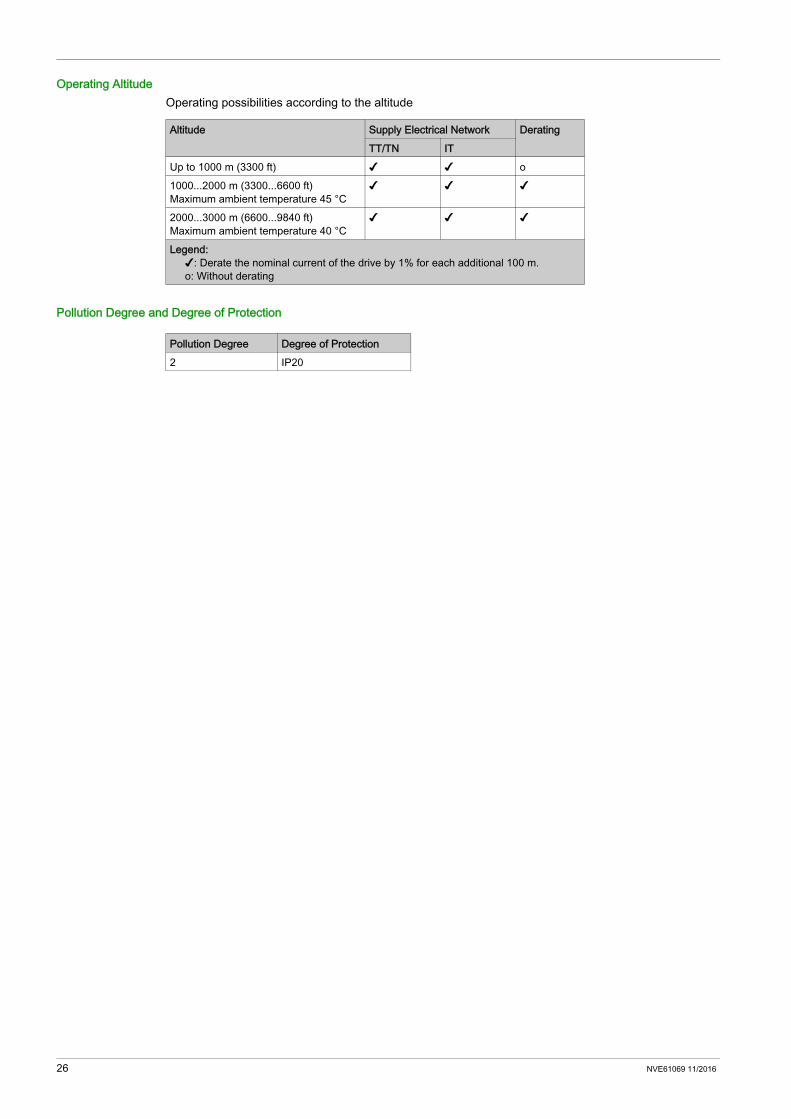
Operating AltitudeOperating possibilities according to the altitude
Pollution Degree and Degree of Protection
Altitude Supply Electrical Network DeratingTT/TN IT
Up to 1000 m (3300 ft) ✔ ✔ o1000...2000 m (3300...6600 ft)Maximum ambient temperature 45 °C
✔ ✔ ✔
2000...3000 m (6600...9840 ft)Maximum ambient temperature 40 °C
✔ ✔ ✔
Legend: ✔: Derate the nominal current of the drive by 1% for each additional 100 m.o: Without derating
Pollution Degree Degree of Protection2 IP20
26 NVE61069 11/2016

Dimensions and Weights
About the drawingsAll drawings CAD files can be downloaded from www.schneider-electric.comNOTE: The dimensions below do not include: a depth increase when using the optional plain text display terminal. On frame sizes 1, 2 and 3, a 50 mm (2 in.) distance for appropriate front control wiring, On frame sizes 4 and 5, a 40 mm (1.58 in) depth increase, if using the additional slot option. This option
module takes place between the graphic display terminal and the drive, causing the depth value to be increased. It enables to connect a safety output module, an I/O or relay output module.
Frame Size 1ATV340U07N4•... ATV340U40N4•
Weights
Catalog Number Weight in kg (lb)ATV340U07N4•, ATV340U15N4• 1.7 (3.7)ATV340U22N4• 1.8 (4)ATV340U30N4 2.1 (4.6)ATV340U30N4E, ATV340U40N4 2.2 (4.8)ATV340U40N4E 2.3 (5.1)
NVE61069 11/2016 27
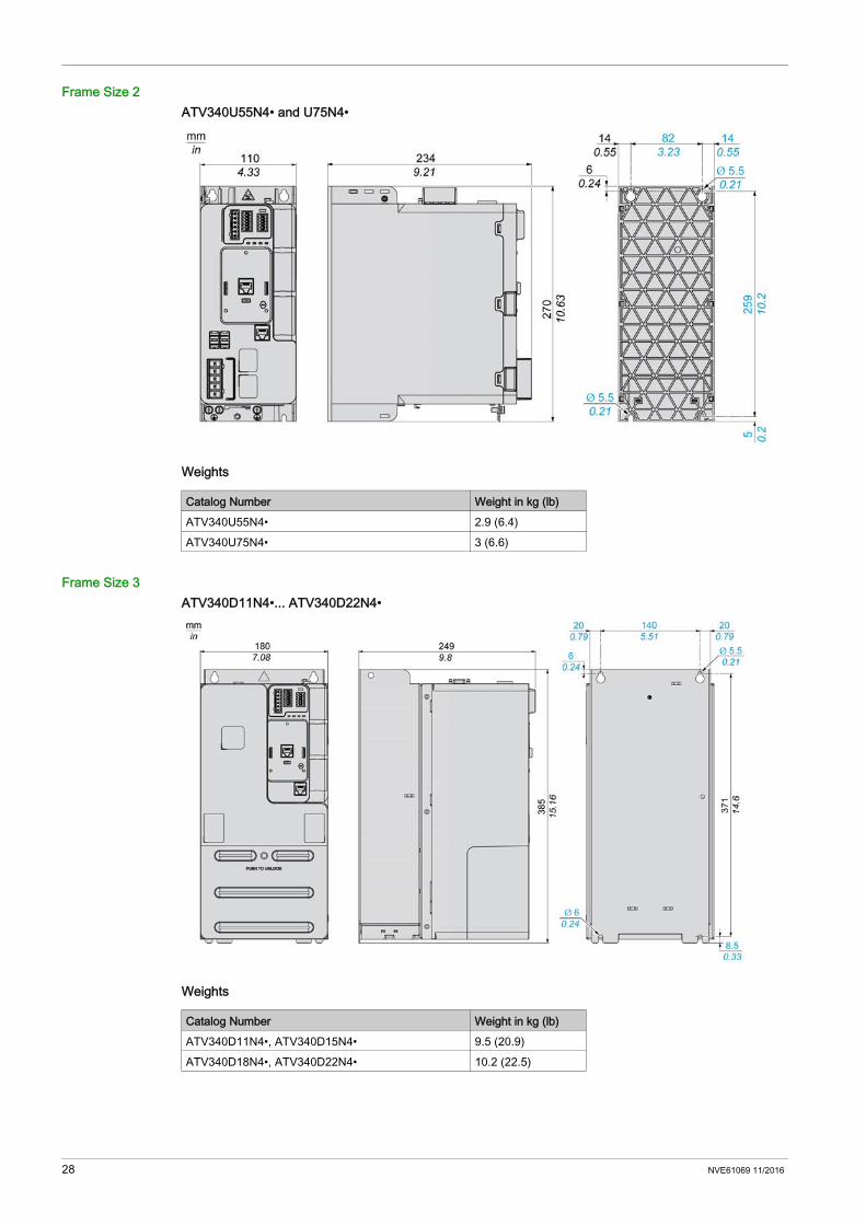
Frame Size 2ATV340U55N4• and U75N4•
Weights
Frame Size 3ATV340D11N4•... ATV340D22N4•
Weights
Catalog Number Weight in kg (lb)ATV340U55N4• 2.9 (6.4)ATV340U75N4• 3 (6.6)
Catalog Number Weight in kg (lb)ATV340D11N4•, ATV340D15N4• 9.5 (20.9)ATV340D18N4•, ATV340D22N4• 10.2 (22.5)
28 NVE61069 11/2016

Frame Size 4ATV340D30N4E... ATV340D37N4E
Weights
Catalog Number Weight in kg (lb)ATV340D30N4E 28.2 (62.2)ATV340D37N4E 28.7 (63.3)
NVE61069 11/2016 29
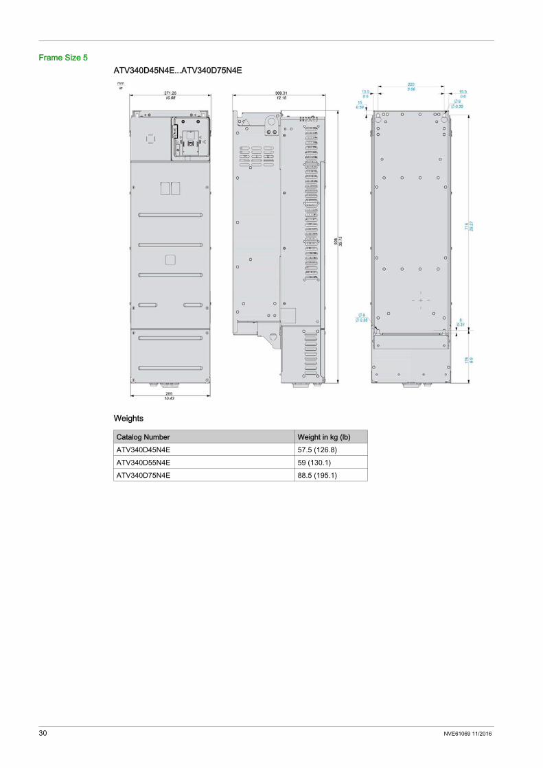
Frame Size 5ATV340D45N4E...ATV340D75N4E
Weights
Catalog Number Weight in kg (lb)ATV340D45N4E 57.5 (126.8)ATV340D55N4E 59 (130.1)ATV340D75N4E 88.5 (195.1)
30 NVE61069 11/2016

Electrical Data
Section 2.2Electrical Data
What Is in This Section?This section contains the following topics:
Topic PageDrive Ratings in Heavy Duty 32Drive Ratings in Normal Duty 34Braking Resistors 36
NVE61069 11/2016 31
Drive Ratings in Heavy Duty
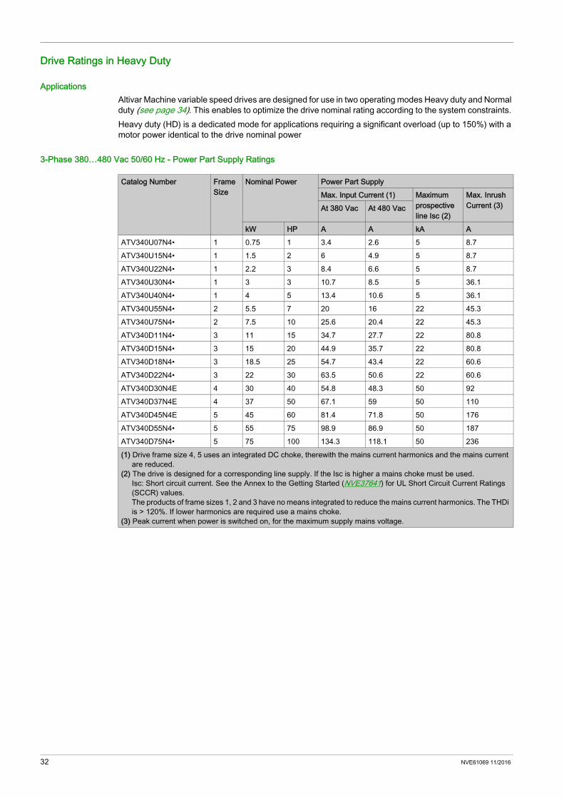
ApplicationsAltivar Machine variable speed drives are designed for use in two operating modes Heavy duty and Normal duty (see page 34). This enables to optimize the drive nominal rating according to the system constraints. Heavy duty (HD) is a dedicated mode for applications requiring a significant overload (up to 150%) with a motor power identical to the drive nominal power
3-Phase 380…480 Vac 50/60 Hz - Power Part Supply Ratings
Catalog Number Frame Size
Nominal Power Power Part SupplyMax. Input Current (1) Maximum
prospective line Isc (2)
Max. Inrush Current (3)At 380 Vac At 480 Vac
kW HP A A kA AATV340U07N4• 1 0.75 1 3.4 2.6 5 8.7ATV340U15N4• 1 1.5 2 6 4.9 5 8.7ATV340U22N4• 1 2.2 3 8.4 6.6 5 8.7ATV340U30N4• 1 3 3 10.7 8.5 5 36.1ATV340U40N4• 1 4 5 13.4 10.6 5 36.1ATV340U55N4• 2 5.5 7 20 16 22 45.3ATV340U75N4• 2 7.5 10 25.6 20.4 22 45.3ATV340D11N4• 3 11 15 34.7 27.7 22 80.8ATV340D15N4• 3 15 20 44.9 35.7 22 80.8ATV340D18N4• 3 18.5 25 54.7 43.4 22 60.6ATV340D22N4• 3 22 30 63.5 50.6 22 60.6ATV340D30N4E 4 30 40 54.8 48.3 50 92ATV340D37N4E 4 37 50 67.1 59 50 110ATV340D45N4E 5 45 60 81.4 71.8 50 176ATV340D55N4• 5 55 75 98.9 86.9 50 187ATV340D75N4• 5 75 100 134.3 118.1 50 236(1) Drive frame size 4, 5 uses an integrated DC choke, therewith the mains current harmonics and the mains current
are reduced.(2) The drive is designed for a corresponding line supply. If the Isc is higher a mains choke must be used.
Isc: Short circuit current. See the Annex to the Getting Started (NVE37641) for UL Short Circuit Current Ratings (SCCR) values.The products of frame sizes 1, 2 and 3 have no means integrated to reduce the mains current harmonics. The THDi is > 120%. If lower harmonics are required use a mains choke.
(3) Peak current when power is switched on, for the maximum supply mains voltage.
32 NVE61069 11/2016
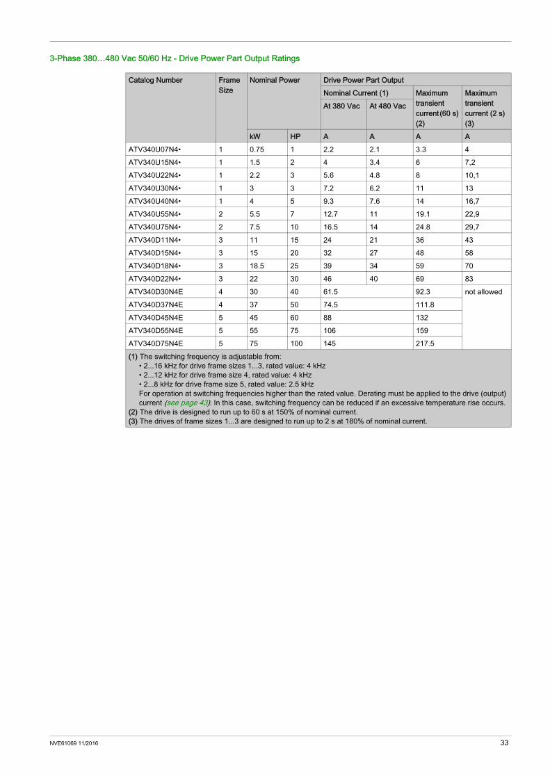
3-Phase 380…480 Vac 50/60 Hz - Drive Power Part Output Ratings
Catalog Number Frame Size
Nominal Power Drive Power Part OutputNominal Current (1) Maximum
transient current (60 s) (2)
Maximum transient current (2 s) (3)
At 380 Vac At 480 Vac
kW HP A A A AATV340U07N4• 1 0.75 1 2.2 2.1 3.3 4ATV340U15N4• 1 1.5 2 4 3.4 6 7,2ATV340U22N4• 1 2.2 3 5.6 4.8 8 10,1ATV340U30N4• 1 3 3 7.2 6.2 11 13ATV340U40N4• 1 4 5 9.3 7.6 14 16,7ATV340U55N4• 2 5.5 7 12.7 11 19.1 22,9ATV340U75N4• 2 7.5 10 16.5 14 24.8 29,7ATV340D11N4• 3 11 15 24 21 36 43ATV340D15N4• 3 15 20 32 27 48 58ATV340D18N4• 3 18.5 25 39 34 59 70ATV340D22N4• 3 22 30 46 40 69 83ATV340D30N4E 4 30 40 61.5 92.3 not allowedATV340D37N4E 4 37 50 74.5 111.8ATV340D45N4E 5 45 60 88 132ATV340D55N4E 5 55 75 106 159ATV340D75N4E 5 75 100 145 217.5(1) The switching frequency is adjustable from:
• 2...16 kHz for drive frame sizes 1...3, rated value: 4 kHz• 2...12 kHz for drive frame size 4, rated value: 4 kHz• 2...8 kHz for drive frame size 5, rated value: 2.5 kHzFor operation at switching frequencies higher than the rated value. Derating must be applied to the drive (output) current (see page 43). In this case, switching frequency can be reduced if an excessive temperature rise occurs.
(2) The drive is designed to run up to 60 s at 150% of nominal current.(3) The drives of frame sizes 1...3 are designed to run up to 2 s at 180% of nominal current.
NVE61069 11/2016 33
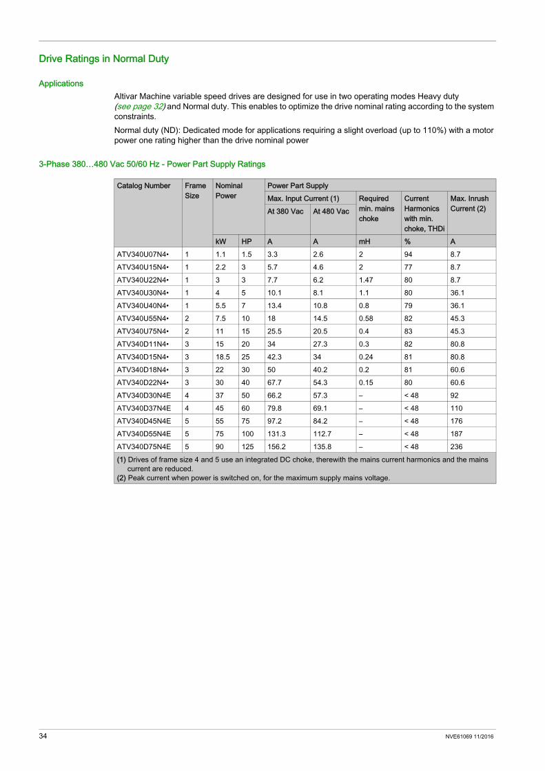
Drive Ratings in Normal Duty
ApplicationsAltivar Machine variable speed drives are designed for use in two operating modes Heavy duty (see page 32) and Normal duty. This enables to optimize the drive nominal rating according to the system constraints.Normal duty (ND): Dedicated mode for applications requiring a slight overload (up to 110%) with a motor power one rating higher than the drive nominal power
3-Phase 380…480 Vac 50/60 Hz - Power Part Supply Ratings
Catalog Number Frame Size
Nominal Power
Power Part SupplyMax. Input Current (1) Required
min. mains choke
Current Harmonics with min. choke, THDi
Max. Inrush Current (2)At 380 Vac At 480 Vac
kW HP A A mH % AATV340U07N4• 1 1.1 1.5 3.3 2.6 2 94 8.7ATV340U15N4• 1 2.2 3 5.7 4.6 2 77 8.7ATV340U22N4• 1 3 3 7.7 6.2 1.47 80 8.7ATV340U30N4• 1 4 5 10.1 8.1 1.1 80 36.1ATV340U40N4• 1 5.5 7 13.4 10.8 0.8 79 36.1ATV340U55N4• 2 7.5 10 18 14.5 0.58 82 45.3ATV340U75N4• 2 11 15 25.5 20.5 0.4 83 45.3ATV340D11N4• 3 15 20 34 27.3 0.3 82 80.8ATV340D15N4• 3 18.5 25 42.3 34 0.24 81 80.8ATV340D18N4• 3 22 30 50 40.2 0.2 81 60.6ATV340D22N4• 3 30 40 67.7 54.3 0.15 80 60.6ATV340D30N4E 4 37 50 66.2 57.3 – < 48 92ATV340D37N4E 4 45 60 79.8 69.1 – < 48 110ATV340D45N4E 5 55 75 97.2 84.2 – < 48 176ATV340D55N4E 5 75 100 131.3 112.7 – < 48 187ATV340D75N4E 5 90 125 156.2 135.8 – < 48 236(1) Drives of frame size 4 and 5 use an integrated DC choke, therewith the mains current harmonics and the mains
current are reduced.(2) Peak current when power is switched on, for the maximum supply mains voltage.
34 NVE61069 11/2016

3-Phase 380…480 Vac 50/60 Hz - Drive Power Part Output RatingsNOTE: At maximum ambient temperature of 40°C (104 °F), use of a mains choke is obligatory for drive frame
size 1, 2 and 3. At maximum ambient temperature of 50°C (122 °F) for drive frame size 4 and 5.
Catalog Number Frame Size
Nominal Power Drive Power Part OutputNominal Current (1) Maximum
transient current (60 s) (2)
Maximum transient current (2 s) (3)
At 380 Vac At 480 Vac
kW HP A A A AATV340U07N4• 1 1.1 1.5 2.8 2.6 3.1 3.8ATV340U15N4• 1 2.2 3 5.6 4.8 6.2 7.6ATV340U22N4• 1 3 3 7.2 6.8 7.9 9.7ATV340U30N4• 1 4 5 9.3 7.6 10.2 12.6ATV340U40N4• 1 5.5 7 12.7 11 14 17.1ATV340U55N4• 2 7.5 10 16.5 14 18.2 22.3ATV340U75N4• 2 11 15 24 21 26.4 32.4ATV340D11N4• 3 15 20 32 27 35.2 43.2ATV340D15N4• 3 18.5 25 39 34 42.9 52.7ATV340D18N4• 3 22 30 46 40 50.6 62.1ATV340D22N4• 3 30 40 62 52 68.2 83.7ATV340D30N4E 4 37 50 74.5 89.4 not allowedATV340D37N4E 4 45 60 88 105.6ATV340D45N4E 5 55 75 106 127.2ATV340D55N4E 5 75 100 145 174ATV340D75N4E 5 90 125 173 207.6(1) The switching frequency is adjustable from:
• 2...16 kHz for drive frame sizes 1...3, rated value: 4 kHz• 2...12 kHz for drive frame size 4, rated value: 4 kHz• 2...8 kHz for drive frame size 5, rated value: 2.5 kHzFor operation at switching frequencies higher than the rated value. Derating must be applied to the drive (output) current (see page 43). In this case, switching frequency can be reduced if an excessive temperature rise occurs.
(2) The drive is designed to run up to 60 s at 110% of nominal current for frame sizes 1, 2 and 3.The drive is designed to run up to 60 s at 120% of nominal current for frame sizes 4 and 5.
(3) The drives of frame sizes 1...3 are designed to run up to 2 s at 135% of nominal current.
NVE61069 11/2016 35

Braking Resistors
GeneralBraking resistors allow the drives to operate while braking to a standstill or during slowdown braking, by dissipating the braking energy. They enable maximum transient braking torque. For a detailed description and catalog numbers, refer to the Catalog on www.schneider-electric.com
Minimum Resistor ValuesMinimum allowed value of the resistor to be connected
Catalog Number Minimum Value in Ω
Catalog Number Minimum Value in Ω
ATV340U07N4• 78 ATV340D15N4• 16ATV340U15N4• 52 ATV340D18N4• 13ATV340U22N4• 52 ATV340D22N4• 10ATV340U30N4• 31 ATV340D30N4E 10ATV340U40N4• 31 ATV340D37N4E 10ATV340U55N4• 31 ATV340D45N4E 2.5ATV340U75N4• 28 ATV340D55N4E 2.5ATV340D11N4• 16 ATV340D75N4E 2.5
36 NVE61069 11/2016

Altivar Machine ATV340
NVE61069 11/2016
Drive Mounting
Chapter 3Drive Mounting
What Is in This Chapter?This chapter contains the following topics:
Topic PageMounting Conditions 38Derating Curves 43Mounting Procedures 50
NVE61069 11/2016 37
Mounting Conditions
Before You BeginConductive foreign objects, dust or liquids or damaged parts may cause parasitic voltage.
The temperature of the products described in this manual may exceed 80 °C (176 °F) during operation.
Power Drive Systems (PDS) can generate strong local electrical and magnetic fields. This can cause interference in electromagnetically sensitive devices.
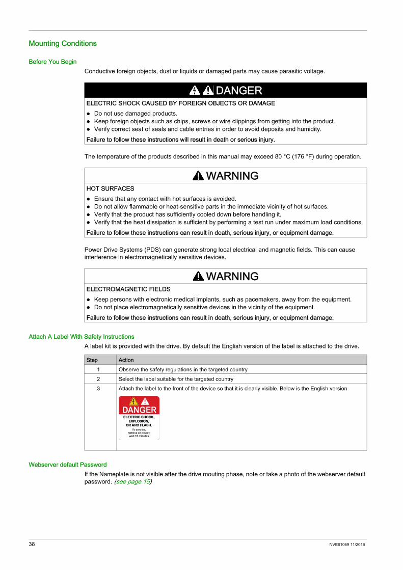
Attach A Label With Safety InstructionsA label kit is provided with the drive. By default the English version of the label is attached to the drive.
Webserver default PasswordIf the Nameplate is not visible after the drive mouting phase, note or take a photo of the webserver default password. (see page 15)
DANGERELECTRIC SHOCK CAUSED BY FOREIGN OBJECTS OR DAMAGE Do not use damaged products. Keep foreign objects such as chips, screws or wire clippings from getting into the product. Verify correct seat of seals and cable entries in order to avoid deposits and humidity.Failure to follow these instructions will result in death or serious injury.
WARNINGHOT SURFACES Ensure that any contact with hot surfaces is avoided. Do not allow flammable or heat-sensitive parts in the immediate vicinity of hot surfaces. Verify that the product has sufficiently cooled down before handling it. Verify that the heat dissipation is sufficient by performing a test run under maximum load conditions.Failure to follow these instructions can result in death, serious injury, or equipment damage.
WARNINGELECTROMAGNETIC FIELDS Keep persons with electronic medical implants, such as pacemakers, away from the equipment. Do not place electromagnetically sensitive devices in the vicinity of the equipment.Failure to follow these instructions can result in death, serious injury, or equipment damage.
Step Action1 Observe the safety regulations in the targeted country2 Select the label suitable for the targeted country3 Attach the label to the front of the device so that it is clearly visible. Below is the English version
38 NVE61069 11/2016
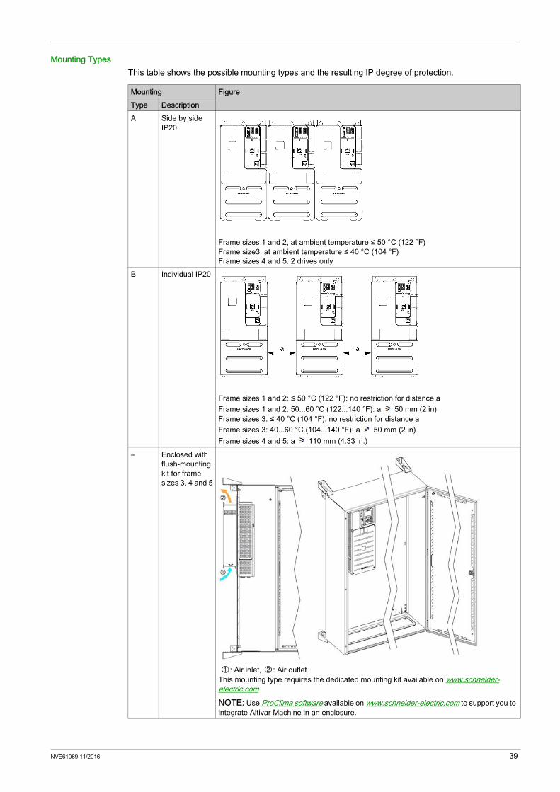
Mounting TypesThis table shows the possible mounting types and the resulting IP degree of protection.
Mounting FigureType DescriptionA Side by side
IP20
Frame sizes 1 and 2, at ambient temperature ≤ 50 °C (122 °F)Frame size3, at ambient temperature ≤ 40 °C (104 °F)Frame sizes 4 and 5: 2 drives only
B Individual IP20
Frame sizes 1 and 2: ≤ 50 °C (122 °F): no restriction for distance aFrame sizes 1 and 2: 50...60 °C (122...140 °F): a 50 mm (2 in)Frame sizes 3: ≤ 40 °C (104 °F): no restriction for distance aFrame sizes 3: 40...60 °C (104...140 °F): a 50 mm (2 in)Frame sizes 4 and 5: a 110 mm (4.33 in.)
– Enclosed with flush-mounting kit for frame sizes 3, 4 and 5
: Air inlet, : Air outletThis mounting type requires the dedicated mounting kit available on www.schneider-electric.comNOTE: Use ProClima software available on www.schneider-electric.com to support you to integrate Altivar Machine in an enclosure.
NVE61069 11/2016 39
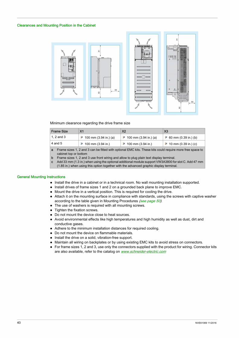
Clearances and Mounting Position in the Cabinet
Minimum clearance regarding the drive frame size
General Mounting Instructions Install the drive in a cabinet or in a technical room. No wall mounting installation supported. Install drives of frame sizes 1 and 2 on a grounded back plane to improve EMC. Mount the drive in a vertical position. This is required for cooling the drive. Attach it on the mounting surface in compliance with standards, using the screws with captive washer
according to the table given in Mounting Procedures (see page 50). The use of washers is required with all mounting screws. Tighten the fixation screws. Do not mount the device close to heat sources. Avoid environmental effects like high temperatures and high humidity as well as dust, dirt and
conductive gases. Adhere to the minimum installation distances for required cooling. Do not mount the device on flammable materials. Install the drive on a solid, vibration-free support. Maintain all wiring on backplates or by using existing EMC kits to avoid stress on connectors. For frame sizes 1, 2 and 3, use only the connectors supplied with the product for wiring. Connector kits
are also available, refer to the catalog on www.schneider-electric.com
Frame Size X1 X2 X31, 2 and 3 100 mm (3.94 in.) (a) 100 mm (3.94 in.) (a) 60 mm (0.39 in.) (b)
4 and 5 100 mm (3.94 in.) 100 mm (3.94 in.) 10 mm (0.39 in.) (c)
a Frame sizes 1, 2 and 3 can be fitted with optional EMC kits. These kits could require more free space to cabinet top or bottom
b Frame sizes 1, 2 and 3 use front wiring and allow to plug plain text display terminal.c Add 33 mm (1.3 in.) when using the optional additional module support VW3A3800 for slot C. Add 47 mm
(1.85 in.) when using this option together with the advanced graphic display terminal.
40 NVE61069 11/2016
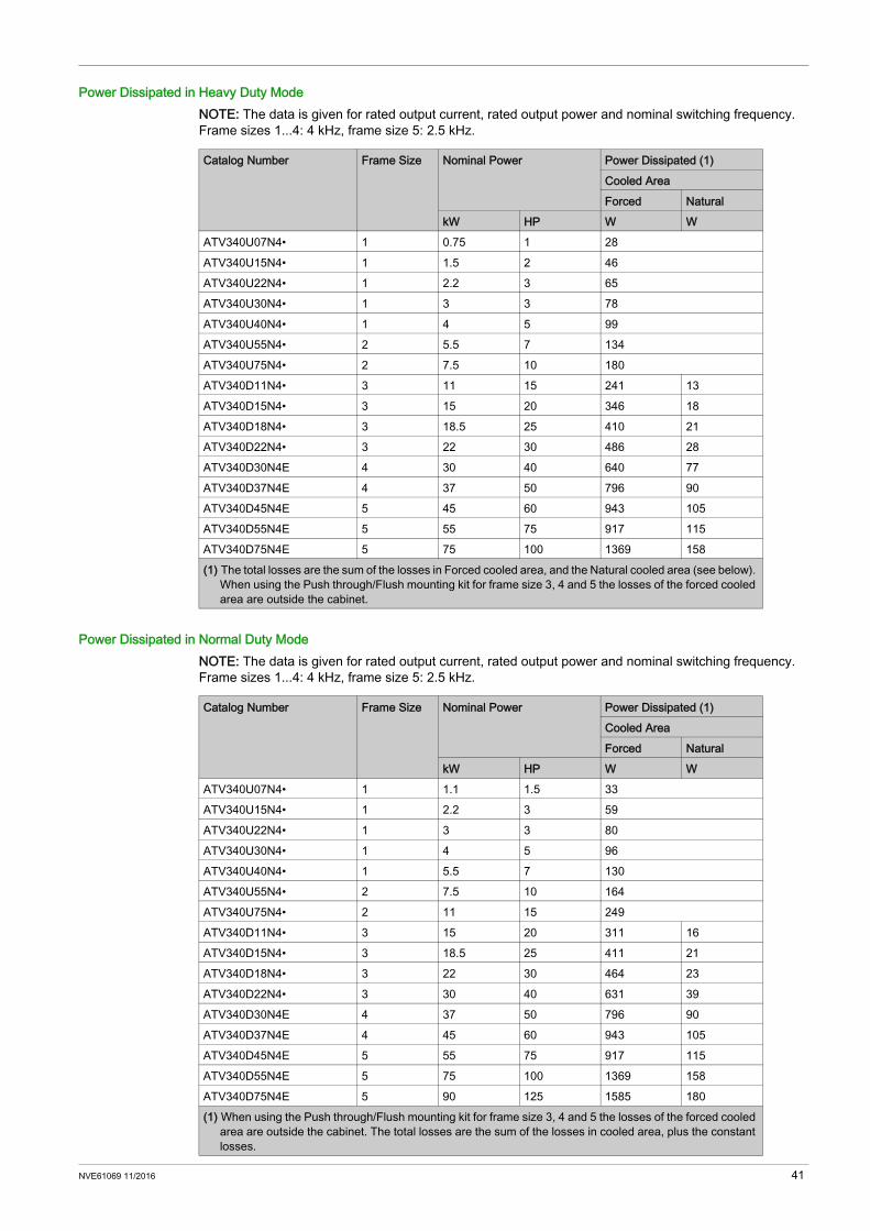
Power Dissipated in Heavy Duty ModeNOTE: The data is given for rated output current, rated output power and nominal switching frequency. Frame sizes 1...4: 4 kHz, frame size 5: 2.5 kHz.
Power Dissipated in Normal Duty ModeNOTE: The data is given for rated output current, rated output power and nominal switching frequency. Frame sizes 1...4: 4 kHz, frame size 5: 2.5 kHz.
Catalog Number Frame Size Nominal Power Power Dissipated (1)Cooled AreaForced Natural
kW HP W WATV340U07N4• 1 0.75 1 28ATV340U15N4• 1 1.5 2 46ATV340U22N4• 1 2.2 3 65ATV340U30N4• 1 3 3 78ATV340U40N4• 1 4 5 99ATV340U55N4• 2 5.5 7 134ATV340U75N4• 2 7.5 10 180ATV340D11N4• 3 11 15 241 13ATV340D15N4• 3 15 20 346 18ATV340D18N4• 3 18.5 25 410 21ATV340D22N4• 3 22 30 486 28ATV340D30N4E 4 30 40 640 77ATV340D37N4E 4 37 50 796 90ATV340D45N4E 5 45 60 943 105ATV340D55N4E 5 55 75 917 115ATV340D75N4E 5 75 100 1369 158(1) The total losses are the sum of the losses in Forced cooled area, and the Natural cooled area (see below).
When using the Push through/Flush mounting kit for frame size 3, 4 and 5 the losses of the forced cooled area are outside the cabinet.
Catalog Number Frame Size Nominal Power Power Dissipated (1)Cooled AreaForced Natural
kW HP W WATV340U07N4• 1 1.1 1.5 33ATV340U15N4• 1 2.2 3 59ATV340U22N4• 1 3 3 80ATV340U30N4• 1 4 5 96ATV340U40N4• 1 5.5 7 130ATV340U55N4• 2 7.5 10 164ATV340U75N4• 2 11 15 249ATV340D11N4• 3 15 20 311 16ATV340D15N4• 3 18.5 25 411 21ATV340D18N4• 3 22 30 464 23ATV340D22N4• 3 30 40 631 39ATV340D30N4E 4 37 50 796 90ATV340D37N4E 4 45 60 943 105ATV340D45N4E 5 55 75 917 115ATV340D55N4E 5 75 100 1369 158ATV340D75N4E 5 90 125 1585 180(1) When using the Push through/Flush mounting kit for frame size 3, 4 and 5 the losses of the forced cooled
area are outside the cabinet. The total losses are the sum of the losses in cooled area, plus the constant losses.
NVE61069 11/2016 41

Constant LossesNOTE: If an interface is not used, the associated losses must not be considered.
Device Connector Losses in WDisplay terminal HMI 1.5Analog IOs CN6 1.5Onboard Encoder CN3 0.5Module Slot A/GP-FB - 3Module Slot B/GP-ENC - 3Module Slot C/GP-SF / Advanced Ethernet - / Eth1, 2 1Digital inputs CN6 1200 mA output CN2 4.8Sum: 16.3
42 NVE61069 11/2016

Derating Curves
DescriptionDerating curves for the nominal drive current (In) as a function of temperature and switching frequency. Refer to the Mounting Conditions chapter (see page 38) for the mounting types description.
Frame Size 1 - 0.7 kWNo derating required.NOTE: For 60°C operation: Type B mounting required No plain text display terminal plugged
Frame Size 1 - 1.5 kW
40 °C (104 °F) - Mounting type A 50 °C (122 °F) - Mounting type A
In Normal duty, these curves are also valid for a temperature 10°C less than the given temperatures.
NOTE: For 60°C operation: Type B mounting required No plain text display terminal plugged No current derating needed
NVE61069 11/2016 43
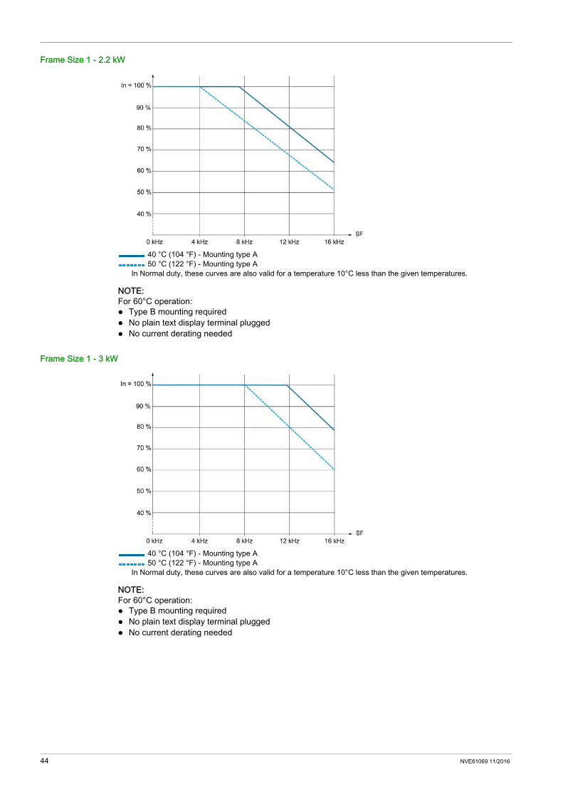
Frame Size 1 - 2.2 kW
40 °C (104 °F) - Mounting type A 50 °C (122 °F) - Mounting type A
In Normal duty, these curves are also valid for a temperature 10°C less than the given temperatures.
NOTE: For 60°C operation: Type B mounting required No plain text display terminal plugged No current derating needed
Frame Size 1 - 3 kW
40 °C (104 °F) - Mounting type A 50 °C (122 °F) - Mounting type A
In Normal duty, these curves are also valid for a temperature 10°C less than the given temperatures.
NOTE: For 60°C operation: Type B mounting required No plain text display terminal plugged No current derating needed
44 NVE61069 11/2016

Frame Size 1 - 4 kW
40 °C (104 °F) - Mounting type A 50 °C (122 °F) - Mounting type A
In Normal duty, these curves are also valid for a temperature 10°C less than the given temperatures.
NOTE: For 60°C operation: Type B mounting required No plain text display terminal plugged No current derating needed
Frame Size 2 - 5.5 kW
40 °C (104 °F) - Mounting type A and B 50 °C (122 °F) - Mounting type A and B 60 °C (140 °F) - Mounting type B
In Normal duty, these curves are also valid for a temperature 10°C less than the given temperatures.
NOTE: For 60°C operation: No side-by-side mounting No plain text display terminal plugged
NVE61069 11/2016 45
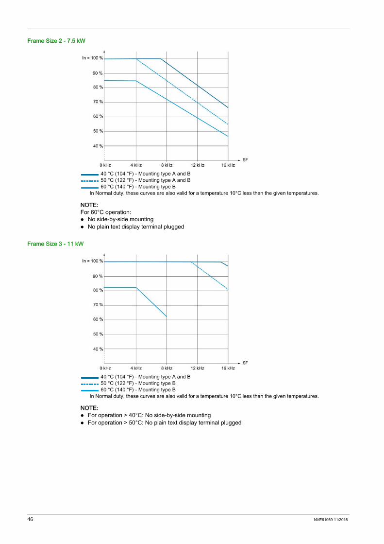
Frame Size 2 - 7.5 kW
40 °C (104 °F) - Mounting type A and B 50 °C (122 °F) - Mounting type A and B 60 °C (140 °F) - Mounting type B
In Normal duty, these curves are also valid for a temperature 10°C less than the given temperatures.
NOTE: For 60°C operation: No side-by-side mounting No plain text display terminal plugged
Frame Size 3 - 11 kW
40 °C (104 °F) - Mounting type A and B 50 °C (122 °F) - Mounting type B 60 °C (140 °F) - Mounting type B
In Normal duty, these curves are also valid for a temperature 10°C less than the given temperatures.
NOTE: For operation > 40°C: No side-by-side mounting For operation > 50°C: No plain text display terminal plugged
46 NVE61069 11/2016

Frame Size 3 - 15 kW
40 °C (104 °F) - Mounting type A and B 50 °C (122 °F) - Mounting type B 60 °C (140 °F) - Mounting type B
In Normal duty, these curves are also valid for a temperature 10°C less than the given temperatures.
NOTE: For operation > 40°C: No side-by-side mounting For operation > 50°C: No plain text display terminal plugged
Frame Size 3 - 18.5 kW
40 °C (104 °F) - Mounting type A and B 50 °C (122 °F) - Mounting type B 60 °C (140 °F) - Mounting type B
In Normal duty, these curves are also valid for a temperature 10°C less than the given temperatures.
NOTE: For operation > 40°C: No side-by-side mounting For operation > 50°C: No plain text display terminal plugged
NVE61069 11/2016 47

Frame Size 3 - 22 kW
40 °C (104 °F) - Mounting type A and B 50 °C (122 °F) - Mounting type B 60 °C (140 °F) - Mounting type B
In Normal duty, these curves are also valid for a temperature 10°C less than the given temperatures.
NOTE: For operation > 40°C: No side-by-side mounting For operation > 50°C: No plain text display terminal plugged
Frame Size 4 - 30 and 37 kW
40 °C (104 °F) - Mounting type A and B 50 °C (122 °F) - Mounting type A and B 60 °C (140 °F) - Mounting type B
48 NVE61069 11/2016
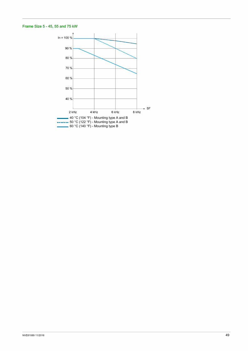
Frame Size 5 - 45, 55 and 75 kW
40 °C (104 °F) - Mounting type A and B 50 °C (122 °F) - Mounting type A and B 60 °C (140 °F) - Mounting type B
NVE61069 11/2016 49
Mounting Procedures
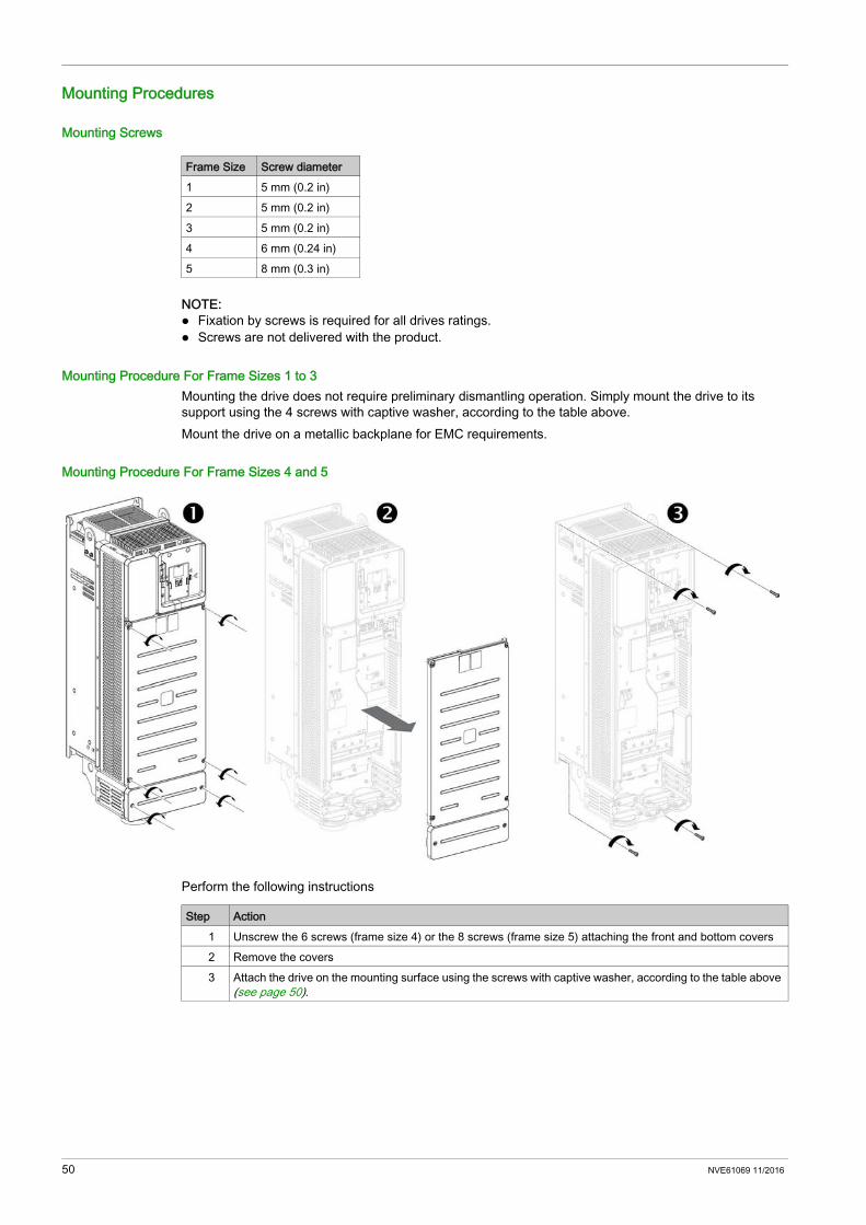
Mounting Screws
NOTE: Fixation by screws is required for all drives ratings. Screws are not delivered with the product.
Mounting Procedure For Frame Sizes 1 to 3Mounting the drive does not require preliminary dismantling operation. Simply mount the drive to its support using the 4 screws with captive washer, according to the table above.Mount the drive on a metallic backplane for EMC requirements.
Mounting Procedure For Frame Sizes 4 and 5
Perform the following instructions
Frame Size Screw diameter1 5 mm (0.2 in)2 5 mm (0.2 in)3 5 mm (0.2 in)4 6 mm (0.24 in)5 8 mm (0.3 in)
Step Action1 Unscrew the 6 screws (frame size 4) or the 8 screws (frame size 5) attaching the front and bottom covers2 Remove the covers3 Attach the drive on the mounting surface using the screws with captive washer, according to the table above
(see page 50).
50 NVE61069 11/2016

Altivar Machine ATV340
NVE61069 11/2016
Drive wiring
Chapter 4Drive wiring
What Is in This Chapter?This chapter contains the following sections:
Section Topic Page4.1 General Wiring Information 524.2 General Wiring Diagrams 594.3 Built-in EMC Filter 654.4 Power Part 694.5 Control Part 794.6 SK EXT SRC Switch Configuration 1034.7 PTO - DQ Switch (SW2) Configuration 1064.8 Safe Torque Off STO Function 1114.9 Digital Inputs Wiring 114
4.10 Digital Outputs Wiring 1184.11 Relay Contacts Wiring 120
NVE61069 11/2016 51

General Wiring Information
Section 4.1General Wiring Information
What Is in This Section?This section contains the following topics:
Topic PageWiring Instructions 53Cable Length Instructions 56Electromagnetic Compatibility 57
52 NVE61069 11/2016
Wiring Instructions
General InstructionsThe entire installation procedure must be performed without voltage present.
Drive systems may perform unexpected movements because of incorrect wiring, incorrect settings, incorrect data or other errors.
The product has a leakage current greater than 3.5 mA. If the protective ground connection is interrupted, a hazardous touch current may flow if the product is touched.
DANGERHAZARD OF ELECTRIC SHOCK, EXPLOSION OR ARC FLASHRead and understand the instructions in Safety Information chapter before performing any procedure in this chapter.Failure to follow these instructions will result in death or serious injury.
WARNINGUNANTICIPATED EQUIPMENT OPERATION Carefully install the wiring in accordance with the EMC requirements. Do not operate the product with unknown or unsuitable settings or data. Perform a comprehensive commissioning test.Failure to follow these instructions can result in death, serious injury, or equipment damage.
WARNINGUNINTENDED BEHAVIOR OF INPUTS AND OUTPUTSThe functions of the inputs and outputs depend on the selected operating mode and the settings of the corresponding parameters. Verify that the wiring is appropriate for the settings. Only start the system if there are no persons or obstructions in the hazardous area. When commissioning, carefully run tests for all operating states and potential error situations.Failure to follow these instructions can result in death, serious injury, or equipment damage.
DANGERHAZARD OF FIRE OR ELECTRIC SHOCK Wire cross sections and tightening torques must comply with the specifications provided in this
document Do not use multi-conductor cables without cable lugs for any connection with a voltage higher than 25
Vac.Failure to follow these instructions will result in death or serious injury.
DANGERELECTRIC SHOCK CAUSED BY HIGH LEAKAGE CURRENT Verify compliance with all local and national electrical code requirements as well as all other applicable
regulations with respect to grounding of the entire drive system.Failure to follow these instructions will result in death or serious injury.
NVE61069 11/2016 53
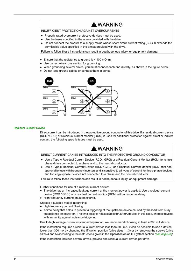
Ensure that the resistance to ground is < 100 mOhm. Use correct wire cross section for grounding. When grounding several drives, you must connect each one directly, as shown in the figure below. Do not loop ground cables or connect them in series.
Residual Current DeviceDirect current can be introduced in the protective ground conductor of this drive. If a residual current device (RCD / GFCI) or a residual current monitor (RCM) is used for additional protection against direct or indirect contact, the following specific types must be used.
Further conditions for use of a residual current device: The drive has an increased leakage current at the moment power is applied. Use a residual current
device (RCD / GFCI) or a residual current monitor (RCM) with a response delay. High-frequency currents must be filtered.Choose a suitable model integrating: High frequency current filtering A time delay that helps to prevent a triggering of the upstream device caused by the load from stray
capacitance on power-on. The time delay is not available for 30 mA device; in this case, choose devices with immunity against nuisance triggering.
Due to high leakage current in standard operation, we recommend choosing at least a 300 mA device.If the installation requires a residual current device less than 300 mA, it can be possible to use a device lower than 300 mA by changing the IT switch position (drive sizes 1...3) or by removing the screws (drive sizes 4 and 5) according to the instructions given in the Operation on an IT System section (see page 66). If the installation includes several drives, provide one residual current device per drive.
WARNINGINSUFFICIENT PROTECTION AGAINST OVERCURRENTS Properly rated overcurrent protective devices must be used. Use the fuses specified in the annex provided with the drive. Do not connect the product to a supply mains whose short-circuit current rating (SCCR) exceeds the
permissible value specified in the annex provided with the drive.Failure to follow these instructions can result in death, serious injury, or equipment damage.
WARNINGDIRECT CURRENT CAN BE INTRODUCED INTO THE PROTECTIVE GROUND CONDUCTOR Use a Type A Residual Current Device (RCD / GFCI) or a Residual Current Monitor (RCM) for single-
phase drives connected to a phase and to the neutral conductor. Use a Type B Residual Current Device (RCD / GFCI) or a Residual Current Monitor (RCM) that has
approval for use with frequency inverters and is sensitive to all types of current for three-phase devices and for single-phase devices not connected to a phase and the neutral conductor.
Failure to follow these instructions can result in death, serious injury, or equipment damage.
54 NVE61069 11/2016
Equipment Grounding
Tighten the grounding screws according to the instructions given in the Ground Cables section (see Altivar 610, Variable Speed Drives, Installation Manual).
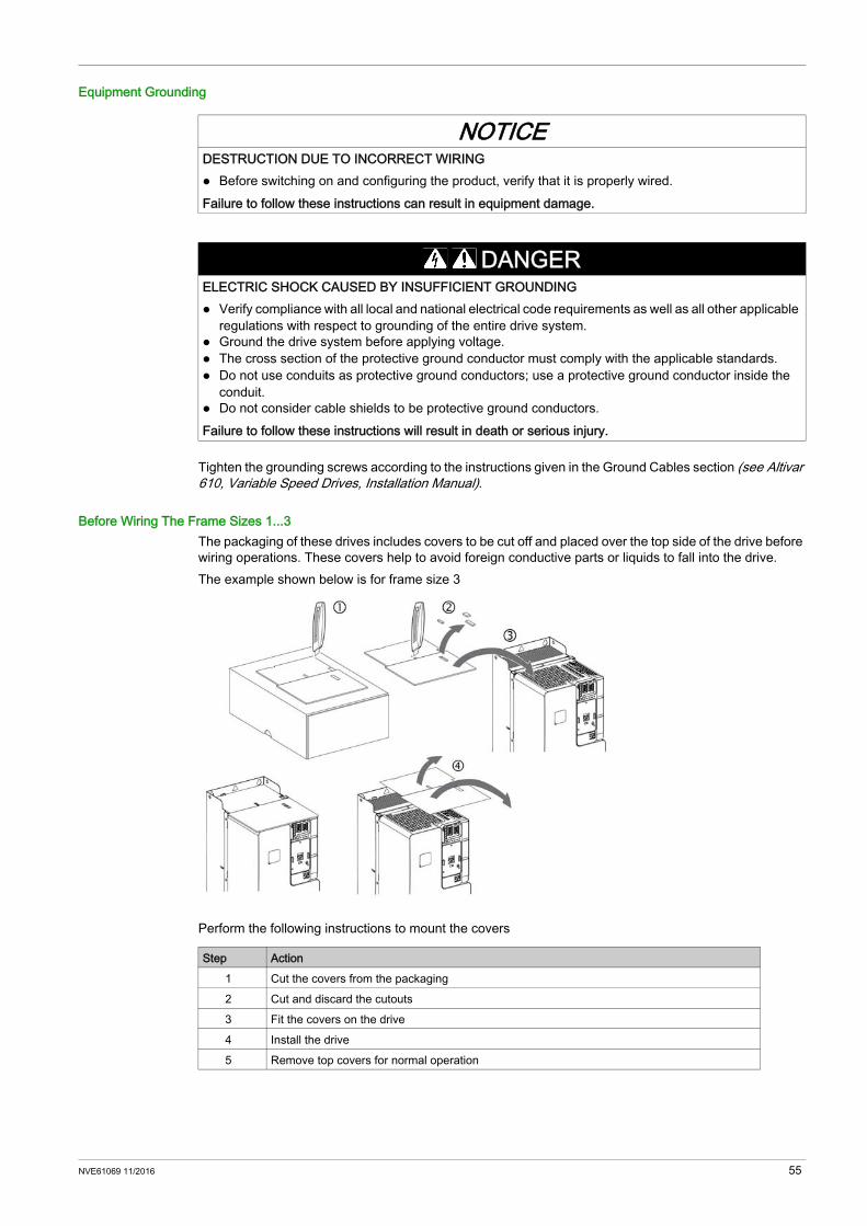
Before Wiring The Frame Sizes 1...3The packaging of these drives includes covers to be cut off and placed over the top side of the drive before wiring operations. These covers help to avoid foreign conductive parts or liquids to fall into the drive.The example shown below is for frame size 3
Perform the following instructions to mount the covers
NOTICEDESTRUCTION DUE TO INCORRECT WIRING Before switching on and configuring the product, verify that it is properly wired.Failure to follow these instructions can result in equipment damage.
DANGERELECTRIC SHOCK CAUSED BY INSUFFICIENT GROUNDING Verify compliance with all local and national electrical code requirements as well as all other applicable
regulations with respect to grounding of the entire drive system. Ground the drive system before applying voltage. The cross section of the protective ground conductor must comply with the applicable standards. Do not use conduits as protective ground conductors; use a protective ground conductor inside the
conduit. Do not consider cable shields to be protective ground conductors.Failure to follow these instructions will result in death or serious injury.
Step Action1 Cut the covers from the packaging2 Cut and discard the cutouts3 Fit the covers on the drive4 Install the drive5 Remove top covers for normal operation
NVE61069 11/2016 55

Cable Length Instructions
Long Cable Lengths ConsequencesNOTE: Maximum cable length is 100 m (328 ft).When drives are used with motors, a combination of fast switching transistors and long motor cables can even cause peak voltages up to twice the DC link voltage. This high peak voltage can cause premature aging of motor winding insulation which leads to motor breakdown.The overvoltage limitation function will enable to increase the cable length while decreasing the torque performances.
Length Of Motor CablesBecause of the permitted mains disturbances, the allowed overvoltages at the motor, the occurring bearing currents and the permitted heat losses the distance between inverter and motor(s) is limited.The maximum distance heavily depends on the used motors (insulation material), the type of motor cable used (shielded/unshielded), as well as the cable laying (cable channel, underground installation...).
Dynamic Voltage Load Of The MotorOvervoltages at the motor terminals result from reflection in the motor cable. Basically the motors are stressed with measurable higher voltage peaks from a motor cable length of 10 m. With the length of the motor cable also the value of overvoltage increases.The steep edges of the switching impulses at the output side of the frequency inverter lead to a further load of the motors. The slew rate of the voltage is typically over 5 kV/μs but it decreases with the length of the motor cableUse a shielded cable to meet the requirements of Category C2 or C3 according to the standard IEC 61800-3.Standard linear capacity cables can be used with Altivar Machine. Use of cables with lower linear capacity could increase cable length performances. To reduce the voltage stress on the motor windings an overvoltage limitation function [Motor surge limit.] SUL can be activated when using long motor cables, within the maximum cable length of 100 m (328 ft), while decreasing the torque performances (refer to Programming manual NVE61643.
Corrective Actions OverviewA number of simple measures can be taken to help enhance the motor life time: Specification of a motor designed for speed drive applications (IEC60034-25 B or NEMA 400 should be
prescribed). Reduce to a minimum the distance between motor and drive. Use unshielded cables.
NOTE: EMC performance not guaranteed with unshielded cables Reduce the drive switching frequency (a reduction to 2.5 kHz is recommended.)
Additional InformationFurther detailed technical information is available in the following white paper An Improved Approach for Connecting VSD and Electric Motors available on www.schneider-electric.com.
56 NVE61069 11/2016
Electromagnetic Compatibility
Limit ValuesThis product meets the EMC requirements according to the standard IEC 61800-3 if the measures described in this manual are implemented during installation. If the selected composition (product itself, mains filter, other accessories and measures) does not meet the requirements of category C1, the following information applies as it appears in IEC 61800-3:
EMC requirements for the control cabinet
Shielded cables
Cable Installation
WARNINGRADIO INTERFERENCEIn a domestic environment this product may cause radio interference in which case supplementary mitigation measures may be required.Failure to follow these instructions can result in death, serious injury, or equipment damage.
EMC measures ObjectiveUse mounting plates with good electrical conductivity, connect large surface areas of metal parts, remove paint from contact areas.
Good conductivity due to large surface contact.
Ground the control cabinet, the control cabinet door and the mounting plate with ground straps or ground wires. The conductor cross section must be at least 10 mm2 (AWG 8).
Reduces emissions.
Fit switching devices such as power contactors, relays or solenoid valves with interference suppression units or arc suppressors (for example, diodes, varistors, RC circuits).
Reduces mutual interference.
Install power components and control components separately.Install frame size 1 and 2 drives on grounded metal back plane. Reduces emissions.
EMC measures ObjectiveConnect large surface areas of cable shields, use cable clamps and ground straps. Reduces emissions.Use cable clamps to connect a large surface area of the shields of all shielded cables to the mounting plate at the control cabinet entry.Ground shields of digital signal wires (see page 59) at both ends by connecting them to a large surface area or via conductive connector housings
Reduces interference affecting the signal wires, reduces emissions
Ground the shields of analog signal wires directly at the device (signal input); insulate the shield at the other cable end or ground it via a capacitor (for example, 10 nF, 100 V or higher.
Reduces ground loops due to low-frequency interference.
Use only shielded motor cables with copper braid and a coverage of at least 85%, ground a large surface area of the shield at both ends.
Diverts interference currents in a controlled way, reduces emissions.
EMC measures ObjectiveDo not route fieldbus cables and signal wires in a single cable duct together with lines with DC and AC voltages of more than 60 V. (Fieldbus cables, signal lines and analog lines may be in the same cable duct)Recommendation: Use separate cable ducts at least 20 cm apart.
Reduces mutual interference.
Keep cables as short as possible. Do not install unnecessary cable loops, use short cables from the central grounding point in the control cabinet to the external ground connection.
Reduces capacitive and inductive interference.
Use equipotential bonding conductors in the following cases: wide-area installations, different voltage supplies and installation across several buildings.
Reduces current in the cable shield, reduces emissions.
Use fine stranded equipotential bonding conductors. Diverts high-frequency interference currents
NVE61069 11/2016 57

Power Supply
Additional measures for EMC improvementDepending on the application, the following measures can improve the EMC-dependent values:
NOTE: If using an additional input filter, it should be mounted side by side to the drive and connected directly to the supply mains via an unshielded cable.
If motor and machine are not conductively connected, for example by an insulated flange or a connection without surface contact, you must ground the motor with a ground strap or a ground wire. The conductor cross section must be at least 10 mm2 (AWG 6).
Reduces emissions, increases immunity.
Use twisted pair for the DC supply.For digital and analog inputs use shielded twisted cables with a pitch of between 25...50 mm (1...2 in).
Reduces interference affecting the signal cables, reduces emissions.
EMC measures Objective
EMC measures ObjectiveOperate product on mains with grounded neutral point. Enables effectiveness of mains
filter.Surge arrester if there is a risk of overvoltage. Reduces the risk of damage
caused by overvoltage.
EMC measures ObjectiveUse mains chokes Reduces mains harmonics,
prolongs product service life.Use external mains filters Improves the EMC limit values.Additional EMC measures, for example mounting in a closed control cabinet with 15 dB shielding attenuation of radiated interference
58 NVE61069 11/2016

General Wiring Diagrams
Section 4.2General Wiring Diagrams
What Is in This Section?This section contains the following topics:
Topic PageWiring Diagrams for Frame Sizes 1...3: ATV340U07N4•...D22N4• 60Wiring Diagrams for Frame Sizes 4 and 5: ATV340D30N4E...D75N4E 63
NVE61069 11/2016 59

Wiring Diagrams for Frame Sizes 1...3: ATV340U07N4•...D22N4•
Control Block Wiring Diagram
(1) 24V In, Out, maximum supply current 200 mA is provided, (2) STO - Safe Torque Off, see ATV340 Embedded safety function manual NVE64143(3) PTI - Pulse Train In, from external source (eg.PLC) Puls - Direction or A-B signals can be connected(4) PTO - Pulse Train Out, can be used to connect to a 2nd ATV340 PTI(5) To connect an motor position feedback encoder(6) Digital output, e.g. to connect a contactor, also usable as DI(7) Digital inputs(8) Analog output, e.g. to connect a meter(9) Analog input, e.g. from potentiometer(10) Differential analog input, e.g. as speed reference from external PLC differential, +/– 10 V(11) Optional
60 NVE61069 11/2016

Three-phase Power Supply - Diagram With Line Contactor Without Safety Function STOConnection diagrams conforming to standards ISO13849 category 1 and IEC/EN 61508 capacity SIL1, stopping category 0 in accordance with standard IEC/EN 60204-1.
(1) Use relay output R1 set to operating state Fault to switch Off the product once an error is detected.
NVE61069 11/2016 61
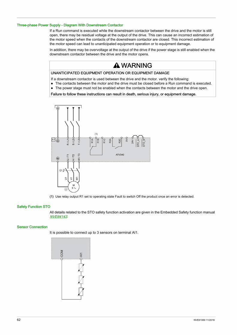
Three-phase Power Supply - Diagram With Downstream ContactorIf a Run command is executed while the downstream contactor between the drive and the motor is still open, there may be residual voltage at the output of the drive. This can cause an incorrect estimation of the motor speed when the contacts of the downstream contactor are closed. This incorrect estimation of the motor speed can lead to unanticipated equipment operation or to equipment damage.In addition, there may be overvoltage at the output of the drive if the power stage is still enabled when the downstream contactor between the drive and the motor opens.
(1) Use relay output R1 set to operating state Fault to switch Off the product once an error is detected.
Safety Function STOAll details related to the STO safety function activation are given in the Embedded Safety function manual NVE64143.
Sensor ConnectionIt is possible to connect up to 3 sensors on terminal AI1.
WARNINGUNANTICIPATED EQUIPMENT OPERATION OR EQUIPMENT DAMAGEIf a downstream contactor is used between the drive and the motor. verify the following: The contacts between the motor and the drive must be closed before a Run command is executed. The power stage must not be enabled when the contacts between the motor and the drive open.Failure to follow these instructions can result in death, serious injury, or equipment damage.
62 NVE61069 11/2016
Wiring Diagrams for Frame Sizes 4 and 5: ATV340D30N4E...D75N4E
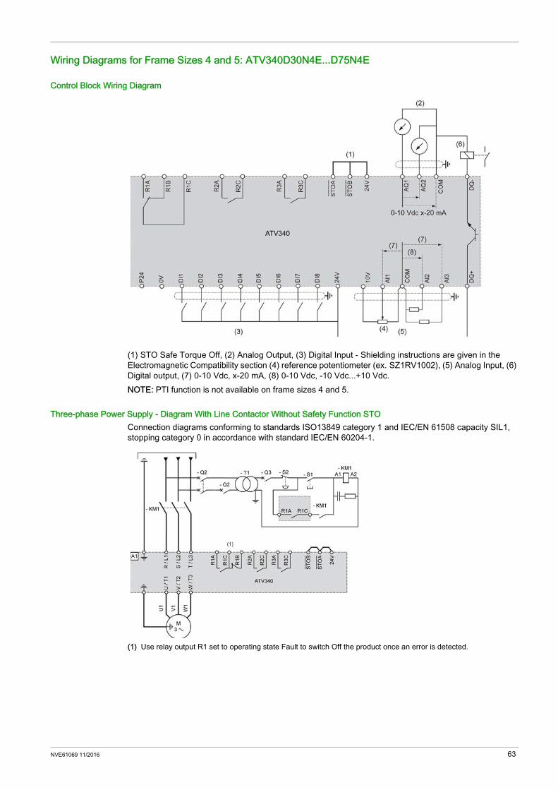
Control Block Wiring Diagram
(1) STO Safe Torque Off, (2) Analog Output, (3) Digital Input - Shielding instructions are given in the Electromagnetic Compatibility section (4) reference potentiometer (ex. SZ1RV1002), (5) Analog Input, (6) Digital output, (7) 0-10 Vdc, x-20 mA, (8) 0-10 Vdc, -10 Vdc...+10 Vdc.NOTE: PTI function is not available on frame sizes 4 and 5.
Three-phase Power Supply - Diagram With Line Contactor Without Safety Function STOConnection diagrams conforming to standards ISO13849 category 1 and IEC/EN 61508 capacity SIL1, stopping category 0 in accordance with standard IEC/EN 60204-1.
(1) Use relay output R1 set to operating state Fault to switch Off the product once an error is detected.
NVE61069 11/2016 63
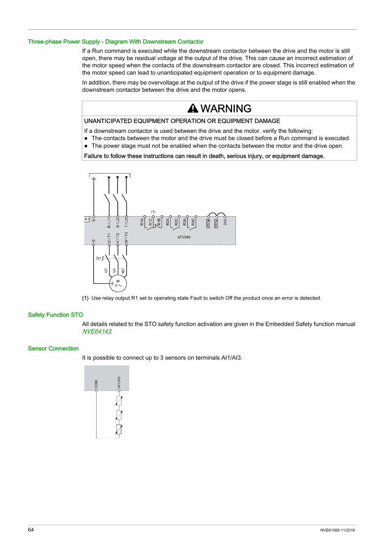
Three-phase Power Supply - Diagram With Downstream ContactorIf a Run command is executed while the downstream contactor between the drive and the motor is still open, there may be residual voltage at the output of the drive. This can cause an incorrect estimation of the motor speed when the contacts of the downstream contactor are closed. This incorrect estimation of the motor speed can lead to unanticipated equipment operation or to equipment damage.In addition, there may be overvoltage at the output of the drive if the power stage is still enabled when the downstream contactor between the drive and the motor opens.
(1) Use relay output R1 set to operating state Fault to switch Off the product once an error is detected.
Safety Function STOAll details related to the STO safety function activation are given in the Embedded Safety function manual NVE64143.
Sensor ConnectionIt is possible to connect up to 3 sensors on terminals AI1/AI3.
WARNINGUNANTICIPATED EQUIPMENT OPERATION OR EQUIPMENT DAMAGEIf a downstream contactor is used between the drive and the motor. verify the following: The contacts between the motor and the drive must be closed before a Run command is executed. The power stage must not be enabled when the contacts between the motor and the drive open.Failure to follow these instructions can result in death, serious injury, or equipment damage.
64 NVE61069 11/2016

Built-in EMC Filter
Section 4.3Built-in EMC Filter
What Is in This Section?This section contains the following topics:
Topic PageOperation on an IT System 66Disconnecting the Built-in EMC Filter 66
NVE61069 11/2016 65

Operation on an IT System
DefinitionIT system: Isolated or impedance grounded neutral. Use a permanent insulation monitoring device compatible with nonlinear loads, such as an XM200 type or equivalent.
Operation
Disconnecting the Built-in EMC Filter
Filter Disconnection
The drives have a built-in EMC filter. As a result they exhibit leakage current to ground. If the leakage current creates compatibility problems with your installation (residual current device or other), then you can reduce the leakage current by deactivating the Y capacitors as shown below. In this configuration the product does not meet the EMC requirements according to the standard IEC 61800-3.
Setting on Frame Sizes 1 and 2Apply the following instructions to disconnect the built-in EMC filter
NOTICERISK OF DAMAGE TO THE DRIVEIf the drive is used on an IT system, the built-in EMC filter must be disconnected as described in this manual.Failure to follow these instructions can result in equipment damage.
DANGERHAZARD OF ELECTRIC SHOCK, EXPLOSION OR ARC FLASHRead and understand the instructions in Safety Information chapter before performing any procedure in this chapter.Failure to follow these instructions will result in death or serious injury.
Step Action1
The switch is factory set to the position as shown on detail
2To disconnect the built-in EMC filter use a screwdriver to set the switch to the position shown on detail
66 NVE61069 11/2016
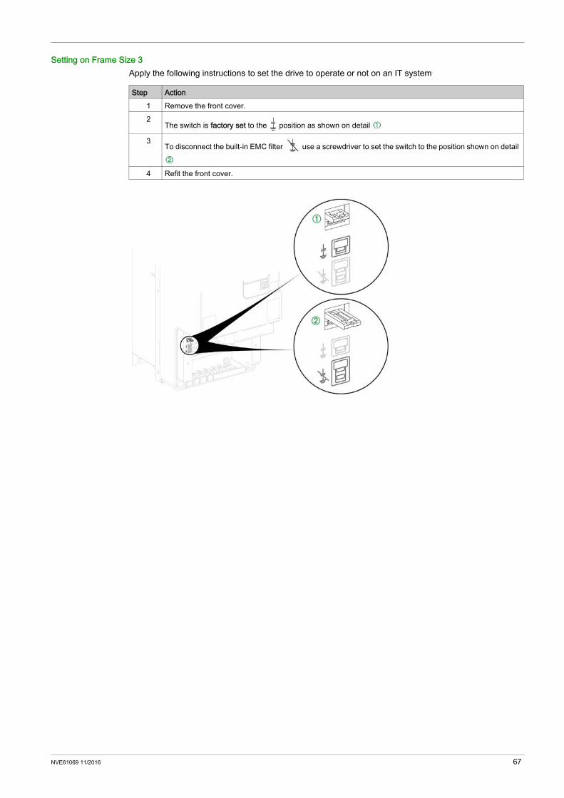
Setting on Frame Size 3Apply the following instructions to set the drive to operate or not on an IT system
Step Action1 Remove the front cover.2
The switch is factory set to the position as shown on detail
3To disconnect the built-in EMC filter use a screwdriver to set the switch to the position shown on detail
4 Refit the front cover.
NVE61069 11/2016 67
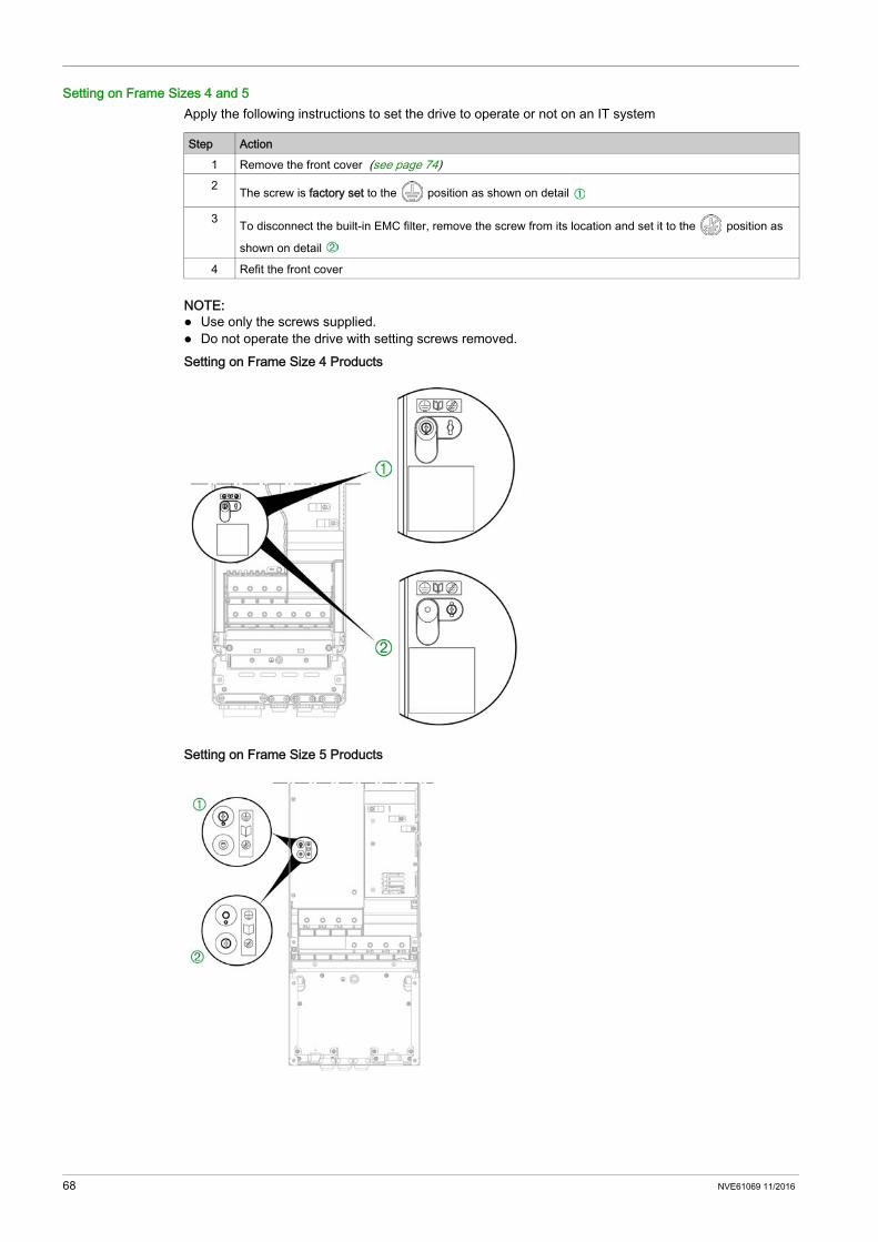
Setting on Frame Sizes 4 and 5Apply the following instructions to set the drive to operate or not on an IT system
NOTE: Use only the screws supplied. Do not operate the drive with setting screws removed.Setting on Frame Size 4 Products
Setting on Frame Size 5 Products
Step Action1 Remove the front cover (see page 74)2 The screw is factory set to the position as shown on detail
3 To disconnect the built-in EMC filter, remove the screw from its location and set it to the position as
shown on detail
4 Refit the front cover
68 NVE61069 11/2016

Power Part
Section 4.4Power Part
What Is in This Section?This section contains the following topics:
Topic PageWiring the Power Part 70Characteristics of the Power Part Terminals 76
NVE61069 11/2016 69

Wiring the Power Part
Power Terminals Arrangement for Frame Sizes 1...2
Functions of the Power Terminals
DANGERHAZARD OF ELECTRIC SHOCK, EXPLOSION OR ARC FLASHVerify that the cables are properly installed as specified in the Characteristics of the Power Part Terminals section.Failure to follow these instructions will result in death or serious injury.
Terminal Connector (on frame sizes 1...2)
Function
L3/T - L2/S - L1/R - CN1 Mains supply and Input ground terminal
PA/+ CN9 DC bus + polarityPC/- CN9 DC bus - polarityW/T3 - V/T2 - U/T1 - PB - PBe CN10 Output motor connection W/T3 - V/T2 - U/T1,
output to braking resistor (1) PB - PBe
Output ground terminal and braking resistor
ground terminal
(1) For further information about the braking resistor option, please refer to the catalog on www.schneider-electric.com.
70 NVE61069 11/2016

Additional PE Ground Terminal ConnectionConnect the additional PE ground terminal of the device to the central grounding point of the system.Additional PE ground terminal location on frame sizes 1 and 2
Access To The Terminals For Frame Size 3
Apply the following instructions to access the terminals on frame size 3 drives
DANGERHAZARD OF ELECTRIC SHOCK, EXPLOSION OR ARC FLASHRead and understand the instructions in Safety Information chapter before performing any procedure in this chapter.Failure to follow these instructions will result in death or serious injury.
Step Action1 Using a screwdriver, push to unlock the cover2 Remove the front cover3 Remove the wiring trap
NVE61069 11/2016 71
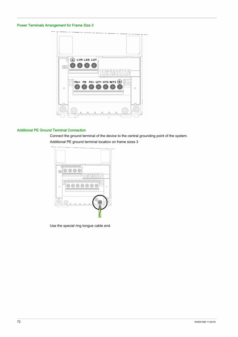
Power Terminals Arrangement for Frame Size 3
Additional PE Ground Terminal ConnectionConnect the ground terminal of the device to the central grounding point of the system.Additional PE ground terminal location on frame sizes 3
Use the special ring tongue cable end.
72 NVE61069 11/2016

Power Cables Routing
Perform the following instructions
Step Action1 Attach and route the motor cable2 Refit the wiring trap3 Attach and route the mains cable4 Refit the power cover
NVE61069 11/2016 73
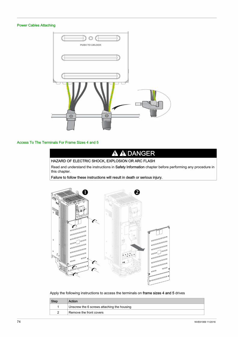
Power Cables Attaching
Access To The Terminals For Frame Sizes 4 and 5
Apply the following instructions to access the terminals on frame sizes 4 and 5 drives
DANGERHAZARD OF ELECTRIC SHOCK, EXPLOSION OR ARC FLASHRead and understand the instructions in Safety Information chapter before performing any procedure in this chapter.Failure to follow these instructions will result in death or serious injury.
Step Action1 Unscrew the 6 screws attaching the housing2 Remove the front covers
74 NVE61069 11/2016
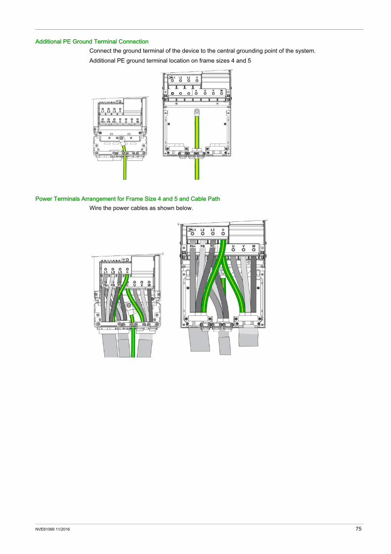
Additional PE Ground Terminal ConnectionConnect the ground terminal of the device to the central grounding point of the system.Additional PE ground terminal location on frame sizes 4 and 5
Power Terminals Arrangement for Frame Size 4 and 5 and Cable PathWire the power cables as shown below.
NVE61069 11/2016 75
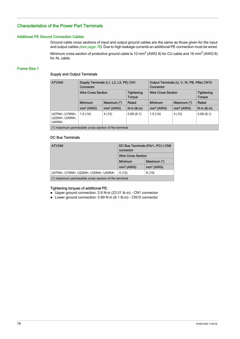
Characteristics of the Power Part Terminals
Additional PE Ground Connection CablesGround cable cross sections of input and output ground cables are the same as those given for the input and output cables (see page 76). Due to high leakage currents an additional PE connection must be wired.
Minimum cross section of protective ground cable is 10 mm2 (AWG 8) for CU cable and 16 mm2 (AWG 6) for AL cable.
Frame Size 1Supply and Output Terminals
DC Bus Terminals
Tightening torques of additional PE: Upper ground connection: 2.6 N·m (23.01 lb.in) - CN1 connector Lower ground connection: 0.69 N·m (6.1 lb.in) - CN10 connector
ATV340 Supply Terminals (L1, L2, L3, PE) CN1 Connector
Output Terminals (U, V, W, PB, PBe) CN10 Connector
Wire Cross Section Tightening Torque
Wire Cross Section Tightening Torque
Minimum Maximum (*) Rated Minimum Maximum (*) Ratedmm² (AWG) mm² (AWG) N·m (lb.in) mm² (AWG) mm² (AWG) N·m (lb.in)
U07N4•, U15N4•, U22N4•, U30N4•, U40N4•
1.5 (14) 4 (12) 0.69 (6.1) 1.5 (14) 4 (12) 0.69 (6.1)
(*) maximum permissible cross section of the terminal
ATV340 DC Bus Terminals (PA/+, PC/-) CN9 connectorWire Cross SectionMinimum Maximum (*)mm² (AWG) mm² (AWG)
U07N4•, U15N4•, U22N4•, U30N4•, U40N4• 4 (12) 6 (10)(*) maximum permissible cross section of the terminal
76 NVE61069 11/2016
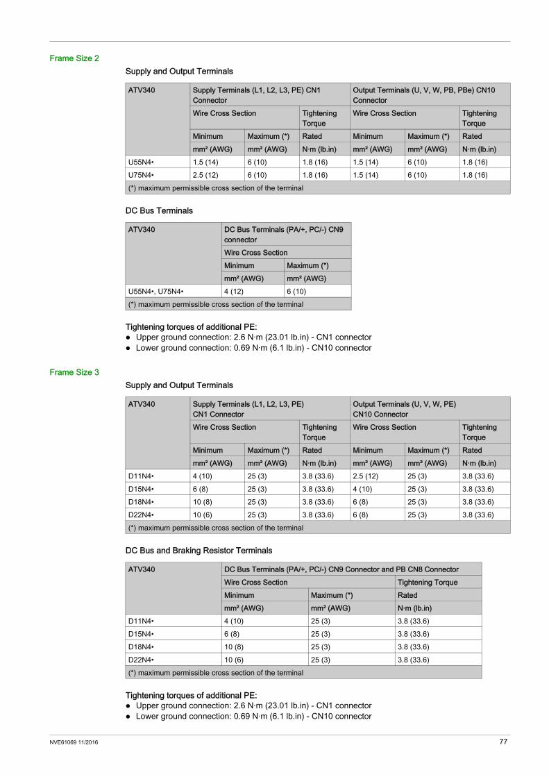
Frame Size 2Supply and Output Terminals
DC Bus Terminals
Tightening torques of additional PE: Upper ground connection: 2.6 N·m (23.01 lb.in) - CN1 connector Lower ground connection: 0.69 N·m (6.1 lb.in) - CN10 connector
Frame Size 3Supply and Output Terminals
DC Bus and Braking Resistor Terminals
Tightening torques of additional PE: Upper ground connection: 2.6 N·m (23.01 lb.in) - CN1 connector Lower ground connection: 0.69 N·m (6.1 lb.in) - CN10 connector
ATV340 Supply Terminals (L1, L2, L3, PE) CN1 Connector
Output Terminals (U, V, W, PB, PBe) CN10 Connector
Wire Cross Section Tightening Torque
Wire Cross Section Tightening Torque
Minimum Maximum (*) Rated Minimum Maximum (*) Ratedmm² (AWG) mm² (AWG) N·m (lb.in) mm² (AWG) mm² (AWG) N·m (lb.in)
U55N4• 1.5 (14) 6 (10) 1.8 (16) 1.5 (14) 6 (10) 1.8 (16)U75N4• 2.5 (12) 6 (10) 1.8 (16) 1.5 (14) 6 (10) 1.8 (16)(*) maximum permissible cross section of the terminal
ATV340 DC Bus Terminals (PA/+, PC/-) CN9 connectorWire Cross SectionMinimum Maximum (*)mm² (AWG) mm² (AWG)
U55N4•, U75N4• 4 (12) 6 (10)(*) maximum permissible cross section of the terminal
ATV340 Supply Terminals (L1, L2, L3, PE) CN1 Connector
Output Terminals (U, V, W, PE) CN10 Connector
Wire Cross Section Tightening Torque
Wire Cross Section Tightening Torque
Minimum Maximum (*) Rated Minimum Maximum (*) Ratedmm² (AWG) mm² (AWG) N·m (lb.in) mm² (AWG) mm² (AWG) N·m (lb.in)
D11N4• 4 (10) 25 (3) 3.8 (33.6) 2.5 (12) 25 (3) 3.8 (33.6)D15N4• 6 (8) 25 (3) 3.8 (33.6) 4 (10) 25 (3) 3.8 (33.6)D18N4• 10 (8) 25 (3) 3.8 (33.6) 6 (8) 25 (3) 3.8 (33.6)D22N4• 10 (6) 25 (3) 3.8 (33.6) 6 (8) 25 (3) 3.8 (33.6)(*) maximum permissible cross section of the terminal
ATV340 DC Bus Terminals (PA/+, PC/-) CN9 Connector and PB CN8 ConnectorWire Cross Section Tightening TorqueMinimum Maximum (*) Ratedmm² (AWG) mm² (AWG) N·m (lb.in)
D11N4• 4 (10) 25 (3) 3.8 (33.6)D15N4• 6 (8) 25 (3) 3.8 (33.6)D18N4• 10 (8) 25 (3) 3.8 (33.6)D22N4• 10 (6) 25 (3) 3.8 (33.6)(*) maximum permissible cross section of the terminal
NVE61069 11/2016 77
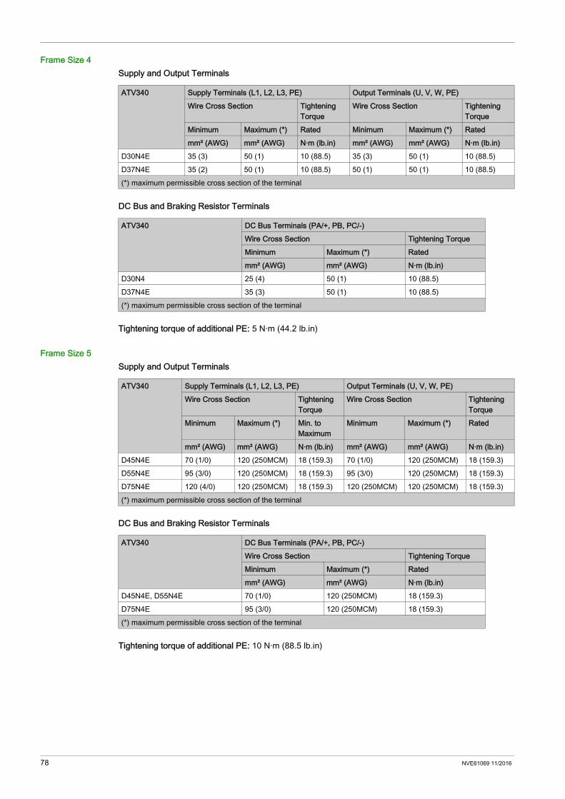
Frame Size 4Supply and Output Terminals
DC Bus and Braking Resistor Terminals
Tightening torque of additional PE: 5 N·m (44.2 lb.in)
Frame Size 5Supply and Output Terminals
DC Bus and Braking Resistor Terminals
Tightening torque of additional PE: 10 N·m (88.5 lb.in)
ATV340 Supply Terminals (L1, L2, L3, PE) Output Terminals (U, V, W, PE)Wire Cross Section Tightening
TorqueWire Cross Section Tightening
TorqueMinimum Maximum (*) Rated Minimum Maximum (*) Ratedmm² (AWG) mm² (AWG) N·m (lb.in) mm² (AWG) mm² (AWG) N·m (lb.in)
D30N4E 35 (3) 50 (1) 10 (88.5) 35 (3) 50 (1) 10 (88.5)D37N4E 35 (2) 50 (1) 10 (88.5) 50 (1) 50 (1) 10 (88.5)(*) maximum permissible cross section of the terminal
ATV340 DC Bus Terminals (PA/+, PB, PC/-)Wire Cross Section Tightening TorqueMinimum Maximum (*) Ratedmm² (AWG) mm² (AWG) N·m (lb.in)
D30N4 25 (4) 50 (1) 10 (88.5)D37N4E 35 (3) 50 (1) 10 (88.5)(*) maximum permissible cross section of the terminal
ATV340 Supply Terminals (L1, L2, L3, PE) Output Terminals (U, V, W, PE)Wire Cross Section Tightening
TorqueWire Cross Section Tightening
TorqueMinimum Maximum (*) Min. to
MaximumMinimum Maximum (*) Rated
mm² (AWG) mm² (AWG) N·m (lb.in) mm² (AWG) mm² (AWG) N·m (lb.in)D45N4E 70 (1/0) 120 (250MCM) 18 (159.3) 70 (1/0) 120 (250MCM) 18 (159.3)D55N4E 95 (3/0) 120 (250MCM) 18 (159.3) 95 (3/0) 120 (250MCM) 18 (159.3)D75N4E 120 (4/0) 120 (250MCM) 18 (159.3) 120 (250MCM) 120 (250MCM) 18 (159.3)(*) maximum permissible cross section of the terminal
ATV340 DC Bus Terminals (PA/+, PB, PC/-)Wire Cross Section Tightening TorqueMinimum Maximum (*) Ratedmm² (AWG) mm² (AWG) N·m (lb.in)
D45N4E, D55N4E 70 (1/0) 120 (250MCM) 18 (159.3)D75N4E 95 (3/0) 120 (250MCM) 18 (159.3)(*) maximum permissible cross section of the terminal
78 NVE61069 11/2016
Control Part
Section 4.5Control Part
What Is in This Section?This section contains the following topics:
Topic PageArrangement and Characteristics of Control Block Terminals, Communication and I/O Ports 80Control Terminals Electrical Data for Frame Sizes 1...3 83Control Terminals Electrical data for Frame Sizes 4 and 5 93Control Wires Cable Path on Frame Sizes 4 and 5 96Product LEDs 100
NVE61069 11/2016 79

Arrangement and Characteristics of Control Block Terminals, Communication and I/O Ports
Front Control Terminals - Drive Frame Sizes 1...3
Top Control Terminals Location on Drive Frame Sizes 1...3
Connector / Switch DescriptionGP-SF Slot for safety and general purpose modules like I/O, RelayGP-ENC Slot for encoder module. Use only VW3A3420, VW3A3422, VW3A3423 modules and general purpose modules like
I/O, RelayHMI RJ45 port for Plain Text Display Terminal (VW3A1113) direct plug-in or Graphic Display Terminal (VW3A1111) to
connect with a cable (see page 17)ETH1 ETH2 2 x RJ45 Advanced Ethernet portsGP-FB Slot for fieldbus and general purpose modules like IO, RelayCN7 Modbus VP12S port (see page 92)SK/EXT/SRC switch Sink-Source switch (see page 103)CN6 Analog and digital I/O, relay outputs... (see page 89)
Connector / Switch DescriptionCN3 ENC Embedded encoder (see page 84)CN4 PTO (Pulse Train Output) (see page 86)CN5 PTI (Pulse Train Input) (see page 86)CN2/STO 24Vdc STO (Safe Torque Off) (see page 83)
80 NVE61069 11/2016
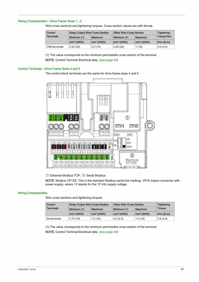
Wiring Characteristics - Drive Frame Sizes 1...3Wire cross sections and tightening torques. Cross section values are with ferrule.
(1) The value corresponds to the minimum permissible cross section of the terminal.NOTE: Control Terminal Electrical data. (see page 83)
Control Terminals - Drive Frame Sizes 4 and 5The control block terminals are the same for drive frame sizes 4 and 5.
Ethernet Modbus TCP, Serial ModbusNOTE: Modbus VP12S: This is the standard Modbus serial link marking. VP•S means connector with power supply, where 12 stands for the 12 Vdc supply voltage.
Wiring CharacteristicsWire cross sections and tightening torques
(1) The value corresponds to the minimum permissible cross section of the terminal.NOTE: Control Terminal Electrical data. (see page 83)
Control Terminals
Relay Output Wire Cross Section Other Wire Cross Section Tightening Torque RnxMinimum (1) Maximum Minimum (1) Maximum
mm² (AWG) mm² (AWG) mm² (AWG) mm² (AWG) N•m (lb.in)CN6 terminals 0.25 (24) 2.5 (14) 0.25 (24) 1 (16) 0.5 (4.4)
Control Terminals
Relay Output Wire Cross Section Other Wire Cross Section Tightening TorqueMinimum (1) Maximum Minimum (1) Maximum
mm² (AWG) mm² (AWG) mm² (AWG) mm² (AWG) N•m (lb.in)All terminals 0.75 (18) 1.5 (16) 0.5 (2.0) 1.5 (16) 0.5 (4.4)
NVE61069 11/2016 81

Control Block Ports
Legend
RJ45 Communication portsThe control block includes 4 RJ45 ports. They allow to connect a: PC Using a commissioning software (SoMove, SoMachine...), to configure and monitor the drive To access the drive webserver
SCADA system PLC system Graphic Display terminal, using Modbus protocol Modbus fieldbusConnection is also possible using optional: Bluetooth Wifi dongle USB/Modbus converterNOTE: Verify that RJ45 cable is not damaged prior to connect it to the product otherwise the power supply of
the control could be lost. Do not plug Ethernet cable in Modbus plug or vice versa. Do not plug PTI, PTO interface cable to Ethernet or Modbus plugs or vice versa. Use different cable colours for Ethernet, Modbus, PTI,PTO to facilitate Fast Device Replacing
operations. Verify the correct wiring of the drive before to switch the system on.
Marking DescriptionDrive status LEDs (see page 100)
RJ45 port to plug directly a plain text display terminal or using a a cable to connect a Graphic display terminal2 x RJ45 ports: ETH1 and ETH2 for Ethernet embedded
SK-EXT-SRC switch SW1 (see page 103)PTO-DQ switch SW2 (see page 106)RJ45 port for Modbus embedded
Slot B, for encoder interface, and GP (general purpose) modules like I/O, Relay,..
Slot A, for fieldbus communication and GP (general purpose) modules like I/O, Relay,..
82 NVE61069 11/2016
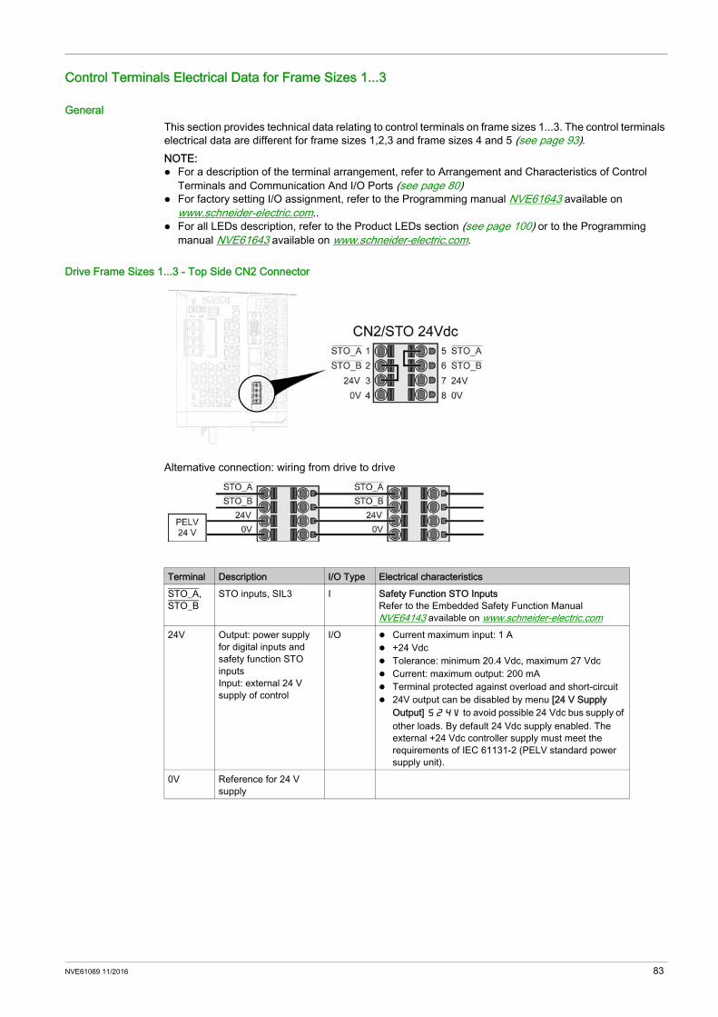
Control Terminals Electrical Data for Frame Sizes 1...3
GeneralThis section provides technical data relating to control terminals on frame sizes 1...3. The control terminals electrical data are different for frame sizes 1,2,3 and frame sizes 4 and 5 (see page 93).NOTE: For a description of the terminal arrangement, refer to Arrangement and Characteristics of Control
Terminals and Communication And I/O Ports (see page 80) For factory setting I/O assignment, refer to the Programming manual NVE61643 available on
www.schneider-electric.com.. For all LEDs description, refer to the Product LEDs section (see page 100) or to the Programming
manual NVE61643 available on www.schneider-electric.com.
Drive Frame Sizes 1...3 - Top Side CN2 Connector
Alternative connection: wiring from drive to drive
Terminal Description I/O Type Electrical characteristicsSTO_A, STO_B
STO inputs, SIL3 I Safety Function STO InputsRefer to the Embedded Safety Function Manual NVE64143 available on www.schneider-electric.com
24V Output: power supply for digital inputs and safety function STO inputsInput: external 24 V supply of control
I/O Current maximum input: 1 A +24 Vdc Tolerance: minimum 20.4 Vdc, maximum 27 Vdc Current: maximum output: 200 mA Terminal protected against overload and short-circuit 24V output can be disabled by menu [24 V Supply
Output] S24V to avoid possible 24 Vdc bus supply of other loads. By default 24 Vdc supply enabled. The external +24 Vdc controller supply must meet the requirements of IEC 61131-2 (PELV standard power supply unit).
0V Reference for 24 V supply
NVE61069 11/2016 83
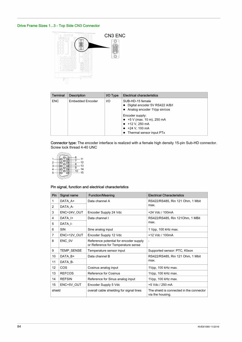
Drive Frame Sizes 1...3 - Top Side CN3 Connector
Connector type: The encoder interface is realized with a female high density 15-pin Sub-HD connector. Screw lock thread 4-40 UNC
Pin signal, function and electrical characteristics
Terminal Description I/O Type Electrical characteristicsENC Embedded Encoder I/O SUB-HD-15 female
Digital encoder 5V RS422 A/B/I Analog encoder 1Vpp sin/cos
Encoder supply: +5 V (max. 10 m), 250 mA +12 V, 250 mA +24 V, 100 mA Thermal sensor input PTx
Pin Signal name Function/Meaning Electrical Characteristics1 DATA_A+ Data channel A RS422/RS485, Rin 121 Ohm, 1 Mbit
max.2 DATA_A-3 ENC+24V_OUT Encoder Supply 24 Vdc +24 Vdc / 100mA4 DATA_I+ Data channel I RS422/RS485, Rin 121Ohm, 1 MBit
max.5 DATA_I-6 SIN Sine analog input 1 Vpp, 100 kHz max.7 ENC+12V_OUT Encoder Supply 12 Vdc +12 Vdc / 100mA8 ENC_0V Reference potential for encoder supply
or Reference for Temperature sense-
9 TEMP_SENSE Temperature sensor input Supported sensor: PTC, Klixon10 DATA_B+ Data channel B RS422/RS485, Rin 121 Ohm, 1 Mbit
max.11 DATA_B-12 COS Cosinus analog input 1Vpp, 100 kHz max.13 REFCOS Reference for Cosinus 1Vpp, 100 kHz max.14 REFSIN Reference for Sinus analog input 1Vpp, 100 kHz max.15 ENC+5V_OUT Encoder Supply 5 Vdc +5 Vdc / 250 mAshield overall cable shielding for signal lines The shield is connected in the connector
via the housing.
84 NVE61069 11/2016

Cable characteristics
Special Features: Wire break detection on DATA_A and DATA_B channel Safety: SIL1 (SC SIL2)NOTE: Cable connector needs to be screwed to CN3 Encoder interface and cable must be maintained on
cabinet backplane and drive top If you add an option module, verify the wiring diagram which is different between the CN3 connector
and the Analog Encoder module (VW3A3422), or the Digital Encoder module (VW3A3420).Cable connection tips: Before connecting the encoder cable check carefully the wiring against above signal table and ensure
that there are no short circuits between signals For 24V encoder supply activation see the parameter [24 V Supply Output] S24V described in the
Programming manual NVE61643 available on www.schneider-electric.com For good EMC performance and connection reliability under vibration ensure proper assembly of
encoder connector to CN3 interface by UNC screw fixing Encoder cable needs to be maintained on top of drive (use cable tie fixation on plastic fin) or cabinet
backplane for strain reliefMaximum cable length according to encoder supply: 12 Vdc / 24 Vdc: 100 m (328 ft) 5 Vdc: 10 m (32 ft)Recommended encoder cable: Encoder cable 100 m (328 ft), ends open, catalog number VW3M8221R1000 1 x 2 x 0.5 mm² (AWG20) for supply line 5 x 2 x 0.25 mm² (AWG26) for signal and sensor lines
Pin Twisted Wire pair digital
Twisted Wire pair analog
ABI sin/cos 1 Vpp
I/O
1 1 NC R - I/O23 4a * 4a * - - O4 3 NC R - I56 NC 2 - R O7 4b * 4b * - - O8 4 or 5 4 or 5 R R9 5 5 Opt. Opt. I10 2 NC R - I1112 NC 3 - R -1314 NC 2 - R O15 4c * 4c * - - Oshield R R*: wired depending on selected supply voltageR: Required-: Not requiredOpt.: Optional
NVE61069 11/2016 85

Drive Frame Sizes 1...3 - Top Side CN4 Connector
Recommended encoder cable: both ends grounded Twisted Pair PELV Minimum conductor cross section: 0.14 mm² (AWG 24) Maximum lenth: 100m (328 ft)
Drive Frame Sizes 1...3 - Top Side CN5 Connector
Recommended encoder cable: both ends grounded Twisted Pair PELV Minimum conductor cross section: 0.14 mm² (AWG 24)
Terminal Description I/O Type Electrical characteristicsPTO Pulse train output O 5 Vdc differential RS422 signals
Logic level as per RS422 Output frequency per signal ≤ 500 kHz Motor increments per second ≤ 1.6*106 Inc/s
Terminal Description I/O Type Electrical characteristicsPTI Pulse train input I 5 Vdc or 24 Vdc signals.
The following signals can be connected: A/B signals P/D signals (Pulse/Direction) CW/CCW signals (ClockWise / CounterClockWise)
86 NVE61069 11/2016
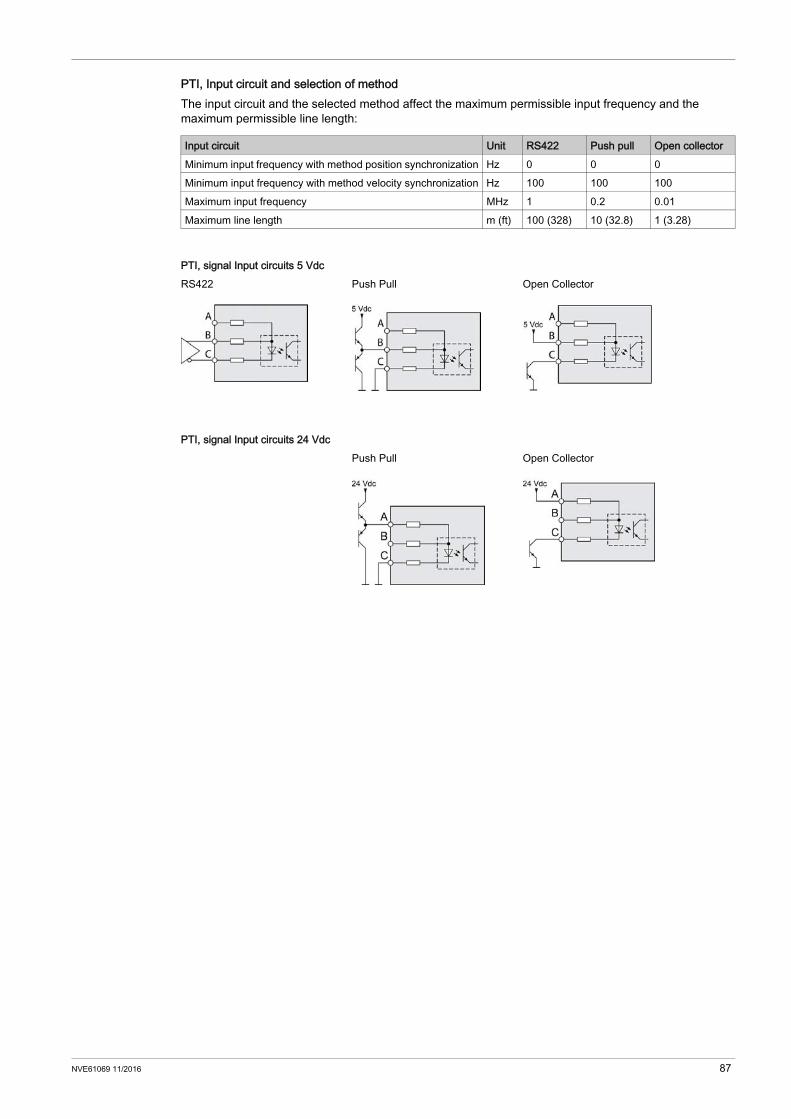
PTI, Input circuit and selection of methodThe input circuit and the selected method affect the maximum permissible input frequency and the maximum permissible line length:
Input circuit Unit RS422 Push pull Open collectorMinimum input frequency with method position synchronization Hz 0 0 0Minimum input frequency with method velocity synchronization Hz 100 100 100Maximum input frequency MHz 1 0.2 0.01Maximum line length m (ft) 100 (328) 10 (32.8) 1 (3.28)
PTI, signal Input circuits 5 VdcRS422 Push Pull Open Collector
PTI, signal Input circuits 24 VdcPush Pull Open Collector
NVE61069 11/2016 87

PTI, Detail of Connector Pins
PTI signal Pin RS422 or 5 Vdc (1) 24 Vdctwisted Pair
Function twisted Pair
Function
A/B 1 A Encoder channel A, 5 Vdc – –2 A Encoder channel A, inverted A Encoder channel A, inverted3 – – –4 B Encoder channel B, 5 Vdc –5 B Encoder channel B, inverted B Encoder channel B, inverted6 – – –7 – – A Encoder channel A, 24 Vdc8 – – B Encoder channel B, 24 Vdc
P/D 1 A Pulse, 5V dc – –2 A Pulse, inverted A Pulse, inverted3 – – –4 B Direction, 5 Vdc – –5 B Direction, inverted B Direction, inverted6 – – –7 – A Pulse, 24 Vdc8 – B Direction, 24 Vdc
CW/CCW 1 A Pulse positive, 5 Vdc – –2 A Pulse positive, inverted A Pulse positive, inverted3 – –4 B Pulse negative, 5 Vdc –5 B Pulse negative, inverted B Pulse negative, inverted6 – –7 – A Pulse positive, 24 Vdc8 – B Pulse negative, 24 Vdc
1) Due to the input current of the optocoupler in the input circuit, a parallel connection of a driver output to several devices is not permitted.
88 NVE61069 11/2016
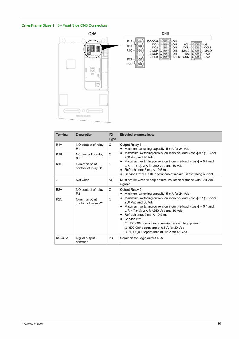
Drive Frame Sizes 1...3 - Front Side CN6 Connectors
Terminal Description I/O Type
Electrical characteristics
R1A NO contact of relay R1
O Output Relay 1 Minimum switching capacity: 5 mA for 24 Vdc Maximum switching current on resistive load: (cos ϕ = 1): 3 A for
250 Vac and 30 Vdc Maximum switching current on inductive load: (cos ϕ = 0.4 and
L/R = 7 ms): 2 A for 250 Vac and 30 Vdc Refresh time: 5 ms +/– 0.5 ms Service life: 100,000 operations at maximum switching current
R1B NC contact of relay R1
O
R1C Common point contact of relay R1
O
– Not wired NC Must not be wired to help ensure insulation distance with 230 VAC signals
R2A NO contact of relay R2
O Output Relay 2 Minimum switching capacity: 5 mA for 24 Vdc Maximum switching current on resistive load: (cos ϕ = 1): 5 A for
250 Vac and 30 Vdc Maximum switching current on inductive load: (cos ϕ = 0.4 and
L/R = 7 ms): 2 A for 250 Vac and 30 Vdc Refresh time: 5 ms +/– 0.5 ms Service life: 100,000 operations at maximum switching power 500,000 operations at 0.5 A for 30 Vdc 1,000,000 operations at 0.5 A for 48 Vac
R2C Common point contact of relay R2
O
DQCOM Digital output common
I/O Common for Logic output DQx
NVE61069 11/2016 89
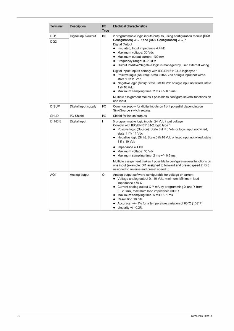
DQ1 Digital input/output I/O 2 programmable logic inputs/outputs, using configuration menus [DQ1 Configuration] do1 and [DQ2 Configuration] do2
Digital Output Insulated, Input impedance 4.4 kΩ Maximum voltage: 30 Vdc Maximum output current: 100 mA Frequency range: 0…1 kHz Output Positive/Negative logic is managed by user external wiring.
Digital Input: Inputs comply with IEC/EN 61131-2 logic type 1 Positive logic (Source): State 0 if≤5 Vdc or logic input not wired,
state 1 if≥11 Vdc Negative logic (Sink): State 0 if≥16 Vdc or logic input not wired, state
1 if≤10 Vdc Maximum sampling time: 2 ms +/– 0.5 ms
Multiple assignment makes it possible to configure several functions on one input
DQ2
DISUP Digital input supply I/O Common supply for digital inputs on front potential depending on Sink/Source switch setting.
SHLD I/O Shield I/O Shield for inputs/outputsDI1-DI5 Digital input I 5 programmable logic inputs. 24 Vdc input voltage
Comply with IEC/EN 61131-2 logic type 1 Positive logic (Source): State 0 if ≤ 5 Vdc or logic input not wired,
state 1 if ≥ 11 Vdc Negative logic (Sink): State 0 if≥16 Vdc or logic input not wired, state
1 if ≤ 10 Vdc Impedance 4.4 kΩ Maximum voltage: 30 Vdc Maximum sampling time: 2 ms +/– 0.5 ms
Multiple assignment makes it possible to configure several functions on one input (example: DI1 assigned to forward and preset speed 2, DI3 assigned to reverse and preset speed 3).
AQ1 Analog output O Analog output software-configurable for voltage or current Voltage analog output 0...10 Vdc, minimum. Minimum load
impedance 470 Ω Current analog output X-Y mA by programming X and Y from
0...20 mA, maximum load impedance 500 Ω Maximum sampling time: 5 ms +/– 1 ms Resolution 10 bits Accuracy: +/– 1% for a temperature variation of 60°C (108°F) Linearity +/– 0.2%
Terminal Description I/O Type
Electrical characteristics
90 NVE61069 11/2016
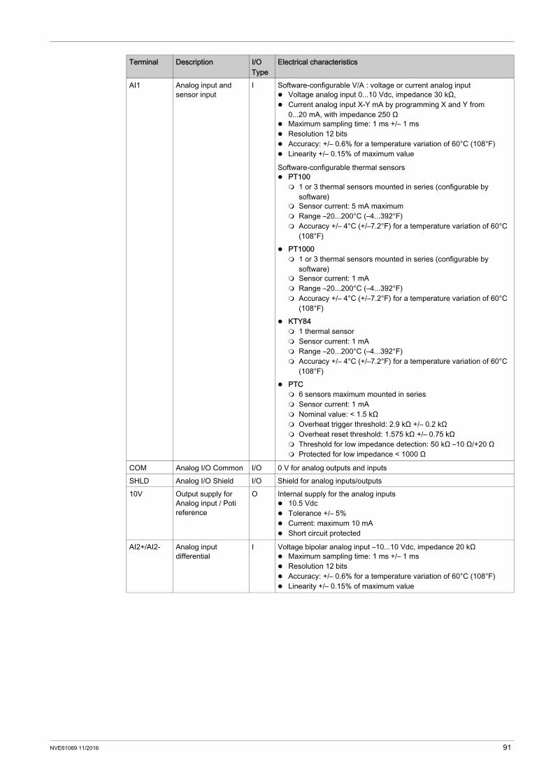
AI1 Analog input and sensor input
I Software-configurable V/A : voltage or current analog input Voltage analog input 0...10 Vdc, impedance 30 kΩ, Current analog input X-Y mA by programming X and Y from
0...20 mA, with impedance 250 Ω Maximum sampling time: 1 ms +/– 1 ms Resolution 12 bits Accuracy: +/– 0.6% for a temperature variation of 60°C (108°F) Linearity +/– 0.15% of maximum value
Software-configurable thermal sensors PT100 1 or 3 thermal sensors mounted in series (configurable by
software) Sensor current: 5 mA maximum Range –20...200°C (–4...392°F) Accuracy +/– 4°C (+/–7.2°F) for a temperature variation of 60°C
(108°F) PT1000 1 or 3 thermal sensors mounted in series (configurable by
software) Sensor current: 1 mA Range –20...200°C (–4...392°F) Accuracy +/– 4°C (+/–7.2°F) for a temperature variation of 60°C
(108°F) KTY84 1 thermal sensor Sensor current: 1 mA Range –20...200°C (–4...392°F) Accuracy +/– 4°C (+/–7.2°F) for a temperature variation of 60°C
(108°F) PTC 6 sensors maximum mounted in series Sensor current: 1 mA Nominal value: < 1.5 kΩ Overheat trigger threshold: 2.9 kΩ +/– 0.2 kΩ Overheat reset threshold: 1.575 kΩ +/– 0.75 kΩ Threshold for low impedance detection: 50 kΩ –10 Ω/+20 Ω Protected for low impedance < 1000 Ω
COM Analog I/O Common I/O 0 V for analog outputs and inputsSHLD Analog I/O Shield I/O Shield for analog inputs/outputs10V Output supply for
Analog input / Poti reference
O Internal supply for the analog inputs 10.5 Vdc Tolerance +/– 5% Current: maximum 10 mA Short circuit protected
AI2+/AI2- Analog input differential
I Voltage bipolar analog input –10...10 Vdc, impedance 20 kΩ Maximum sampling time: 1 ms +/– 1 ms Resolution 12 bits Accuracy: +/– 0.6% for a temperature variation of 60°C (108°F) Linearity +/– 0.15% of maximum value
Terminal Description I/O Type
Electrical characteristics
NVE61069 11/2016 91

Drive Frame Sizes 1...3 - Front Side HMI and CN7 RJ45 Modbus Connectors
HMI: It is intended to connect the optional plain text display terminal or graphic display terminal. Plain text display terminal (VW3A1113): can be either plugged on the drive or mounted on the door of
an enclosure with its dedicated door mounting kit (VW3A1114). Graphic display terminal (VW3A1111): cannot be plugged directly on the drive. It can be connected to
the HMI port using a cable or it can be mounted on the door of an enclosure with its dedicated door mounting kit (VW3A1112)
CN7: RJ45 Modbus VP12S port reserved for modbus fieldbus and commissioning tool.Wiring Diagram - PC with commissioning software
Detail of connector pins
Pin Signal Meaning I/O1...3 - Reserved -4 MOD_D1 Bidirectional transmit/receive signal RS485 level 5 MOD_D0 Bidirectional transmit/receive signal, inverted RS485 level 6 - Reserved -7 MOD+10V_OUT 10 V supply, maximum 100 mA O 8 MOD_0V Reference potential to MOD+10V_OUT
92 NVE61069 11/2016
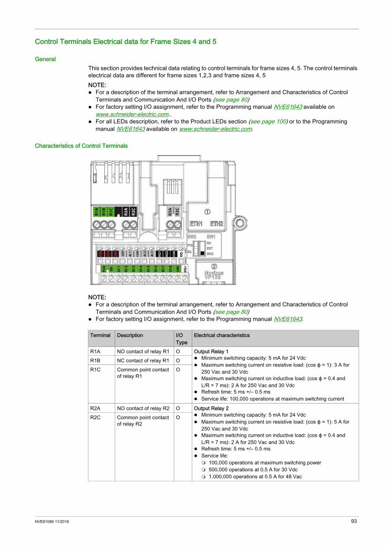
Control Terminals Electrical data for Frame Sizes 4 and 5
GeneralThis section provides technical data relating to control terminals for frame sizes 4, 5. The control terminals electrical data are different for frame sizes 1,2,3 and frame sizes 4, 5NOTE: For a description of the terminal arrangement, refer to Arrangement and Characteristics of Control
Terminals and Communication And I/O Ports (see page 80) For factory setting I/O assignment, refer to the Programming manual NVE61643 available on
www.schneider-electric.com.. For all LEDs description, refer to the Product LEDs section (see page 100) or to the Programming
manual NVE61643 available on www.schneider-electric.com.
Characteristics of Control Terminals
NOTE: For a description of the terminal arrangement, refer to Arrangement and Characteristics of Control
Terminals and Communication And I/O Ports (see page 80) For factory setting I/O assignment, refer to the Programming manual NVE61643.
Terminal Description I/O Type
Electrical characteristics
R1A NO contact of relay R1 O Output Relay 1 Minimum switching capacity: 5 mA for 24 Vdc Maximum switching current on resistive load: (cos ϕ = 1): 3 A for
250 Vac and 30 Vdc Maximum switching current on inductive load: (cos ϕ = 0.4 and
L/R = 7 ms): 2 A for 250 Vac and 30 Vdc Refresh time: 5 ms +/– 0.5 ms Service life: 100,000 operations at maximum switching current
R1B NC contact of relay R1 OR1C Common point contact
of relay R1O
R2A NO contact of relay R2 O Output Relay 2 Minimum switching capacity: 5 mA for 24 Vdc Maximum switching current on resistive load: (cos ϕ = 1): 5 A for
250 Vac and 30 Vdc Maximum switching current on inductive load: (cos ϕ = 0.4 and
L/R = 7 ms): 2 A for 250 Vac and 30 Vdc Refresh time: 5 ms +/– 0.5 ms Service life: 100,000 operations at maximum switching power 500,000 operations at 0.5 A for 30 Vdc 1,000,000 operations at 0.5 A for 48 Vac
R2C Common point contact of relay R2
O
NVE61069 11/2016 93

R3A NO contact of relay R3 O Output Relay 3 Minimum switching capacity: 5 mA for 24 Vdc Maximum switching current on resistive load: (cos ϕ = 1): 5 A for
250 Vac and 30 Vdc Maximum switching current on inductive load: (cos ϕ = 0.4 and
L/R = 7 ms): 2 A for 250 Vac and 30 Vdc Refresh time: 5 ms +/– 0.5 ms Service life: 100,000 operations at maximum switching power 500,000 operations at 0.5 A for 30 Vdc 1,000,000 operations at 0.5 A for 48 Vac
R3C Common point contact of relay R3
O
STOA, STOB
STO inputs I Safety Function STO InputsRefer to the Embedded Safety Function Manual NVE64143 available on www.schneider-electric.com
24V Output power supply for digital inputs and safety function STO inputs
O +24 Vdc Tolerance: minimum 20.4 Vdc, maximum 27 Vdc Current: maximum 200 mA for both 24 Vdc terminals Terminal protected against overload and short-circuit In Sink Ext position, this supply is powered by external PLC supply
10V Output supply for Analog input
O Internal supply for the analog inputs 10.5 Vdc Tolerance +/– 5% Current: maximum 10 mA Short circuit protected
AI1, AI3 Analog input and sensor input
I Software-configurable V/A : voltage or current analog input Voltage analog input 0...10 Vdc, impedance 31.5 kΩ, Current analog input X-Y mA by programming X and Y from
0...20 mA, with impedance 250 Ω Maximum sampling time: 1 ms +/– 1 ms Resolution 12 bits Accuracy: +/– 0.6% for a temperature variation of 60°C (108°F) Linearity +/– 0.15% of maximum value
Software-configurable thermal sensors PT100 1 or 3 thermal sensors mounted in series (configurable by
software) Sensor current: 5 mA maximum Range –20...200°C (–4...392°F) Accuracy +/– 4°C (+/– 7.2°F) for a temperature variation of 60°C
(108°F) PT1000 1 or 3 thermal sensors mounted in series (configurable by
software) Sensor current: 1 mA Range –20...200°C (–4...392°F) Accuracy +/– 4°C (+/– 7.2°F) for a temperature variation of 60°C
(108°F) KTY84 1 thermal sensor Sensor current: 1 mA Range –20...200°C (–4...392°F) Accuracy +/– 4°C (+/– 7.2°F) for a temperature variation of 60°C
(108°F) PTC 6 sensors maximum mounted in series Sensor current: 1 mA Nominal value: < 1.5 kΩ Overheat trigger threshold: 2.9 kΩ +/– 0.2 kΩ Overheat reset threshold: 1.575 kΩ +/– 0.75 kΩ Threshold for low impedance detection: 50 kΩ –10 Ω/+20 Ω Protected for low impedance < 1000 Ω
COM Analog I/O common I/O 0 V for Analog inputs/outputs
Terminal Description I/O Type
Electrical characteristics
94 NVE61069 11/2016

AI2 Analog input I Voltage bipolar analog input –10...10 Vdc, impedance 31.5 kΩ Maximum sampling time: 1 ms +/– 1 ms Resolution 12 bits Accuracy: +/– 0.6% for a temperature variation of 60°C (108°F) Linearity +/– 0.15% of maximum value
AQ1 Analog output O AQ: Analog output software-configurable for voltage or current Voltage analog output 0...10 Vdc, minimum. Minimum load
impedance 470 Ω, Current analog output X-Y mA by programming X and Y from
0...20 mA, maximum load impedance 500 Ω Maximum sampling time: 5 ms +/– 1 ms Resolution 10 bits Accuracy: +/– 1% for a temperature variation of 60°C (108°F) Linearity +/– 0.2%
AQ2 Analog output O
COM Digital and analog output Common
I/O 0 V for analog outputs and logic output
DQ– Digital output O Digital output configurable by switch Insulated Maximum voltage: 30 Vdc Maximum current: 100 mA Frequency range: 0...1 kHz Positive/Negative logic is managed by user external wiring.
DQ+ Digital output O
DQ+ Pulse output O Pulse train output configurable by switch Open collector not insulated Maximum voltage: 30 Vdc Maximum current: 20 mA Frequency range: 0...30 kHz
P24 External input supply I +24 Vdc external input supply Tolerance: minimum 19 Vdc, maximum 30 Vdc Maximum current: 0.8 A
0V 0 V I/O 0 V of P24DI1-DI8 Digital inputs I 8 programmable logic inputs 24 Vdc, comply with IEC/EN 61131-2 logic
type 1 Positive logic (Source): State 0 if 5 Vdc or logic input not wired,
state 1 if 11 Vdc Negative logic (Sink):State 0 if 16 Vdc or logic input not wired,
state 1 if 10 Vdc Impedance 4.4 kΩ Maximum voltage: 30 Vdc Maximum sampling time: 2 ms +/– 0.5 ms
Multiple assignment makes it possible to configure several functions on one input (example: DI1 assigned to forward and preset speed 2, DI3 assigned to reverse and preset speed 3).
DI7-DI8 Pulse inputs I Programmable Pulse input Comply with level 1 PLC, IEC 65A-68 standard State 0 if < 0.6 Vdc, state 1 if > 2.5 Vdc Pulse counter 0...30 kHz Frequency range: 0…30 kHz Cyclic ratio: 50 % +/– 10 % Maximum input voltage 30 Vdc, < 10 mA Maximum sampling time: 5 ms +/– 1 ms
Terminal Description I/O Type
Electrical characteristics
NVE61069 11/2016 95

Control Wires Cable Path on Frame Sizes 4 and 5
Optional Module Installation and WiringApply the following instructions to install and connect a module to be wired
NOTE: Cabling plate shown is for frame size 4. Other cabling plates slightly differs from this one.
Step Action1 Insert the module in the slot A or B.
2 Insert the cable in the cabling plate, according to the outlined locations. The breakable cut out is used for fieldbus cables.
3 Connect the cable to the module
96 NVE61069 11/2016
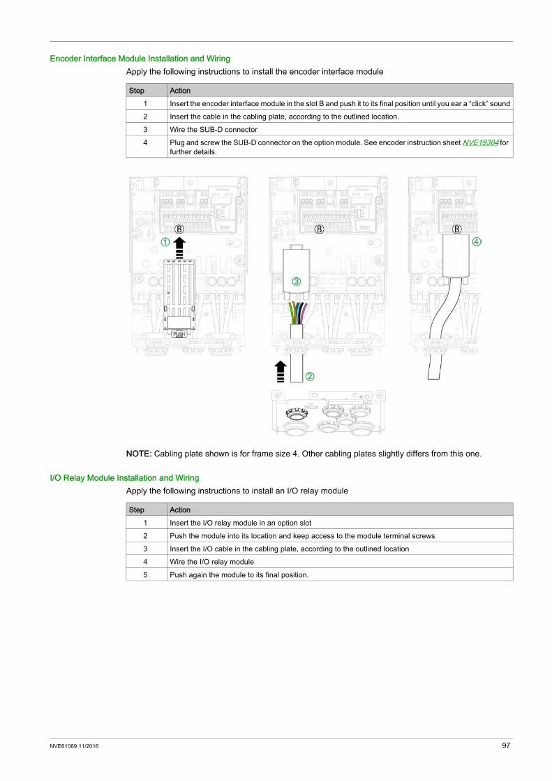
Encoder Interface Module Installation and WiringApply the following instructions to install the encoder interface module
NOTE: Cabling plate shown is for frame size 4. Other cabling plates slightly differs from this one.
I/O Relay Module Installation and WiringApply the following instructions to install an I/O relay module
Step Action1 Insert the encoder interface module in the slot B and push it to its final position until you ear a “click” sound2 Insert the cable in the cabling plate, according to the outlined location.3 Wire the SUB-D connector4 Plug and screw the SUB-D connector on the option module. See encoder instruction sheet NVE19304 for
further details.
Step Action1 Insert the I/O relay module in an option slot2 Push the module into its location and keep access to the module terminal screws3 Insert the I/O cable in the cabling plate, according to the outlined location4 Wire the I/O relay module5 Push again the module to its final position.
NVE61069 11/2016 97
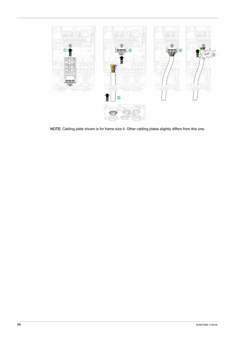
NOTE: Cabling plate shown is for frame size 4. Other cabling plates slightly differs from this one.
98 NVE61069 11/2016
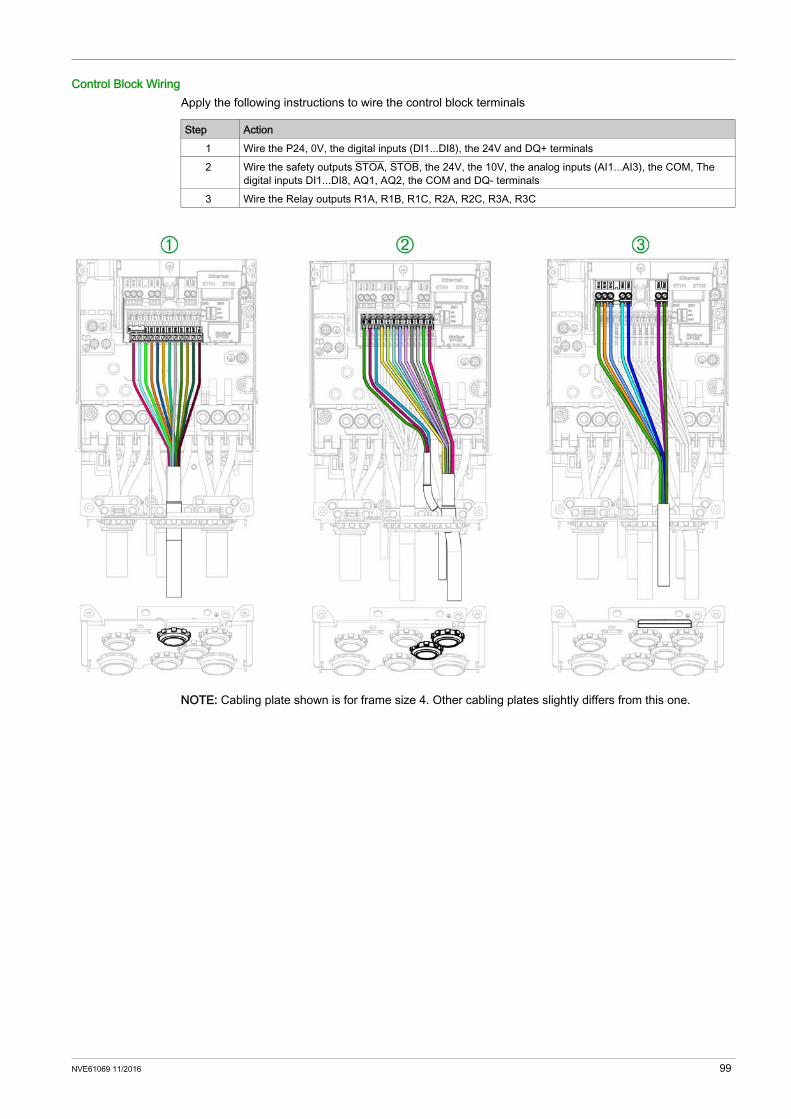
Control Block WiringApply the following instructions to wire the control block terminals
NOTE: Cabling plate shown is for frame size 4. Other cabling plates slightly differs from this one.
Step Action1 Wire the P24, 0V, the digital inputs (DI1...DI8), the 24V and DQ+ terminals2 Wire the safety outputs STOA, STOB, the 24V, the 10V, the analog inputs (AI1...AI3), the COM, The
digital inputs DI1...DI8, AQ1, AQ2, the COM and DQ- terminals3 Wire the Relay outputs R1A, R1B, R1C, R2A, R2C, R3A, R3C
NVE61069 11/2016 99
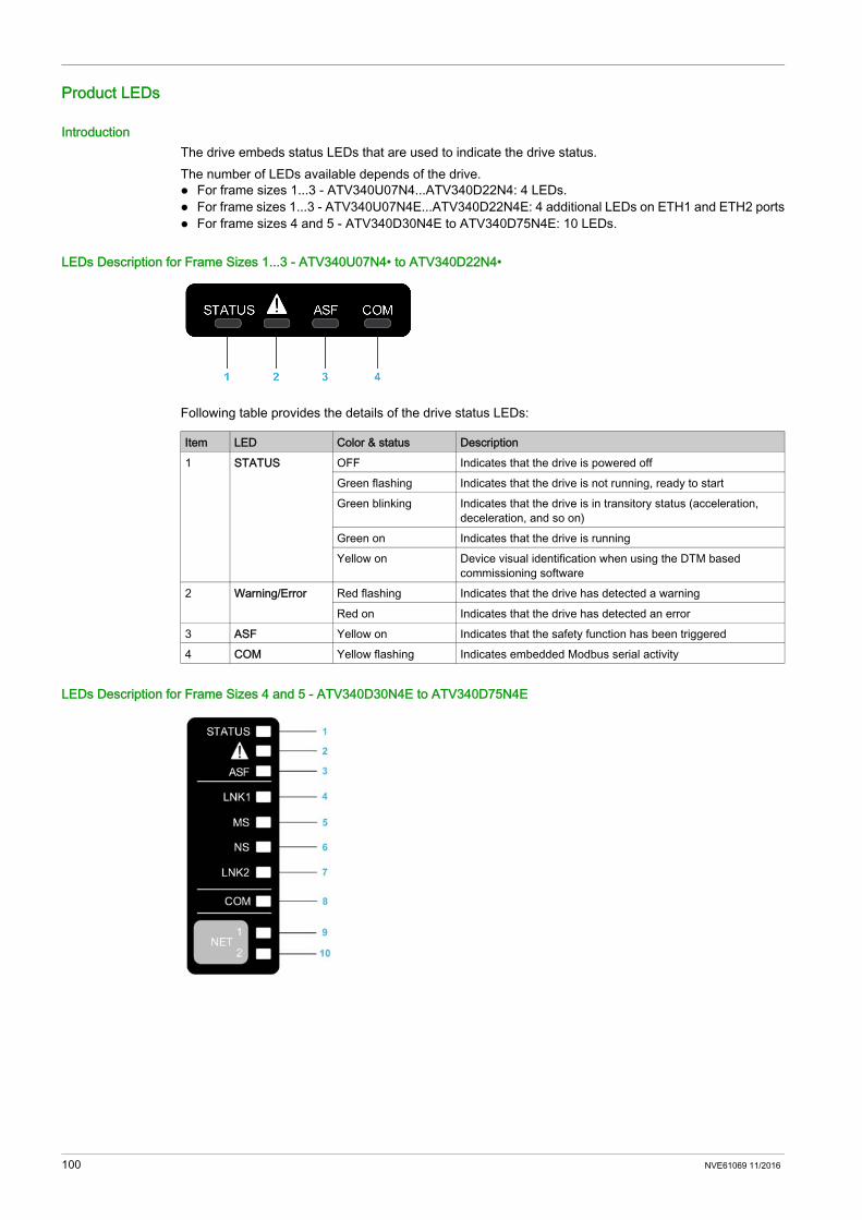
Product LEDs
IntroductionThe drive embeds status LEDs that are used to indicate the drive status.The number of LEDs available depends of the drive. For frame sizes 1...3 - ATV340U07N4...ATV340D22N4: 4 LEDs. For frame sizes 1...3 - ATV340U07N4E...ATV340D22N4E: 4 additional LEDs on ETH1 and ETH2 ports For frame sizes 4 and 5 - ATV340D30N4E to ATV340D75N4E: 10 LEDs.
LEDs Description for Frame Sizes 1...3 - ATV340U07N4• to ATV340D22N4•
Following table provides the details of the drive status LEDs:
LEDs Description for Frame Sizes 4 and 5 - ATV340D30N4E to ATV340D75N4E
Item LED Color & status Description1 STATUS OFF Indicates that the drive is powered off
Green flashing Indicates that the drive is not running, ready to startGreen blinking Indicates that the drive is in transitory status (acceleration,
deceleration, and so on)Green on Indicates that the drive is runningYellow on Device visual identification when using the DTM based
commissioning software2 Warning/Error Red flashing Indicates that the drive has detected a warning
Red on Indicates that the drive has detected an error3 ASF Yellow on Indicates that the safety function has been triggered4 COM Yellow flashing Indicates embedded Modbus serial activity
100 NVE61069 11/2016

Following table provides the details of the drive status LEDs:
Following table provides the details of the embedded Ethernet LEDs:
Following table provides the details of the embedded Modbus serial LEDs:
Following table provides the details of the fieldbus module (for slot A - GP-FB) LEDs:
Item LED Color & status Description1 STATUS OFF Indicates that the drive is powered off
Green flashing Indicates that the drive is not running, ready to startGreen blinking Indicates that the drive is in transitory status (acceleration,
deceleration, and so on)Green on Indicates that the drive is runningYellow on Device Visual identification function when using SoMove or the
device DTM2 Warning/Error Red flashing Indicates that the drive has detected a warning
Red on Indicates that the drive has detected an error3 ASF Yellow on Indicates that the safety function has been triggered
Item LED Color & status Description4 LNK1 OFF No link.
Green/Yellow flashing Power on testing.Green on Link established at 100 Mbit/s.Green flashing Link established at 10 Mbit/s.Yellow flashing Fieldbus activity at 100 Mbit/s.Yellow on Fieldbus activity at 10 Mbit/s.
5 MS OFF No power is supplied to the device.Green/Red flashing Power up testing.Green on The device is operating correctly.Green flashing The device has not been configured.Red flashing The device has detected a recoverable minor detected error.Red on The device has detected a non-recoverable major detected
error.6 NS OFF The device does not have an IP address or powered off.
Green/Red flashing Power on testing.Green on A connection is established to control the command word.Green flashing Device has a valid IP, but no command word connection.Red flashing Duplicated IP.Red on An established connection to control the command word is
closes or timed out.7 LNK2 OFF No link.
Green/Yellow flashing Power on testing.Green on Link established at 100 Mbit/s.Green flashing Link established at 10 Mbit/s.Yellow flashing Fieldbus activity at 100 Mbit/s.Yellow on Fieldbus activity at 10 Mbit/s.
Item LED Color & status Description8 COM Yellow flashing Indicates embedded Modbus serial activity
Item LED Color & status Description9 NET 1 Green/Red for details, refer to the fieldbus manual10 NET 2 Green/Red for details, refer to the fieldbus manual
NVE61069 11/2016 101
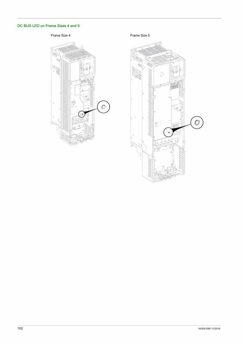
DC BUS LED on Frame Sizes 4 and 5
Frame Size 4 Frame Size 5
102 NVE61069 11/2016

SK EXT SRC Switch Configuration
Section 4.6SK EXT SRC Switch Configuration
What Is in This Section?This section contains the following topics:
Topic PageSK-EXT-SRC Switch Configuration on Frame Sizes 1...3: ATV340U07N4•...D22N4• 104SK-EXT-SRC Switch SW1 Configuration on Frame Sizes 4 and 5: ATV340D30N4E...D75N4E 105
NVE61069 11/2016 103

SK-EXT-SRC Switch Configuration on Frame Sizes 1...3: ATV340U07N4•...D22N4•
Switch DescriptionThe switch markings correspond to the following:
The switch is used to adapt the operation of the digital inputs to the technology of the programmable controller outputs. The switch is located below the HMI port. It has only influence to DIx and DQx used in digital input mode.
Settings
WARNINGUNANTICIPATED EQUIPMENT OPERATION If the drive is set to SK or EXT, do not connect the 0 V terminal to ground or to protective ground. Verify that accidental grounding of digital inputs configured for sink logic, caused, for example, by
damage to the signal cables, cannot occur. Follow all applicable standards and directives such as NFPA 79 and EN 60204 for proper control
circuit grounding practices.Failure to follow these instructions can result in death, serious injury, or equipment damage.
Marking DescriptionSK Sink internalEXT Sink externalSRC Source
Switch Position Description Power SupplySource Set the switch to SRC Source (factory setting) if using PLC outputs
with PNP transistors. Positive Logic PLC. Outputs switches to +24V when active. Common to Europe PLCs.
DISUP: 24 VdcCan be used to supply 24 Vdc to switches.
External (sink)
Switch Set to EXT (Sink external) position and use of an External Power Supply
DISUP: To be connected to 24 Vdc to supply all DIx internal logic
Sink Set the switch to SK (Sink internal) if using PLC outputs with NPN transistors. Negative Logic PLC, Outputs switches to 0 V when active. Common to Asian PLCs.
DISUP: 0VCan be used to supply 0V to switches
104 NVE61069 11/2016
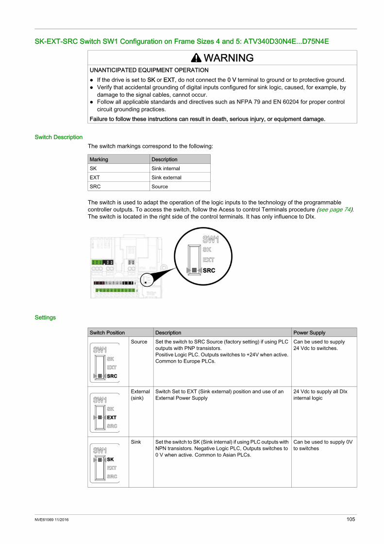
SK-EXT-SRC Switch SW1 Configuration on Frame Sizes 4 and 5: ATV340D30N4E...D75N4E
Switch DescriptionThe switch markings correspond to the following:
The switch is used to adapt the operation of the logic inputs to the technology of the programmable controller outputs. To access the switch, follow the Acess to control Terminals procedure (see page 74). The switch is located in the right side of the control terminals. It has only influence to DIx.
Settings
WARNINGUNANTICIPATED EQUIPMENT OPERATION If the drive is set to SK or EXT, do not connect the 0 V terminal to ground or to protective ground. Verify that accidental grounding of digital inputs configured for sink logic, caused, for example, by
damage to the signal cables, cannot occur. Follow all applicable standards and directives such as NFPA 79 and EN 60204 for proper control
circuit grounding practices.Failure to follow these instructions can result in death, serious injury, or equipment damage.
Marking DescriptionSK Sink internalEXT Sink externalSRC Source
Switch Position Description Power SupplySource Set the switch to SRC Source (factory setting) if using PLC
outputs with PNP transistors. Positive Logic PLC. Outputs switches to +24V when active. Common to Europe PLCs.
Can be used to supply 24 Vdc to switches.
External (sink)
Switch Set to EXT (Sink external) position and use of an External Power Supply
24 Vdc to supply all DIx internal logic
Sink Set the switch to SK (Sink internal) if using PLC outputs with NPN transistors. Negative Logic PLC, Outputs switches to 0 V when active. Common to Asian PLCs.
Can be used to supply 0V to switches
NVE61069 11/2016 105
PTO - DQ Switch (SW2) Configuration
Section 4.7PTO - DQ Switch (SW2) Configuration
What Is in This Section?This section contains the following topics:
Topic PagePTO, Pulse Train Output Configuration on Frame Sizes 4 and 5 107Digital Output Configuration on Frame Sizes 4 and 5 109
106 NVE61069 11/2016

PTO, Pulse Train Output Configuration on Frame Sizes 4 and 5
Purpose
The SW2 (PTO/DQ) switch is used to configure the DQ+ or DQ- digital outputs. Set the switch to PTO (Pulse Train Output) to configure DQ+ and DQ- outputs as pulse train outputs.
This may be used to chain pulse train inputs of another drive, using its DI7 or DI8 pulse inputs. Set the switch to DQ (Digital Output) to configure DQ+ and DQ- outputs as an assignable logic output.
AccessTo access the switch, follow the Access to control Terminals procedure (see page 74). The switch is located below the control terminals (see page 81).
Switch SW1 Set to SK (Sink mode) Position
Switch SW1 Set to EXT (Sink ext mode) Position
Switch SW1 Set to SRC (Source mode) Position
WARNINGUNANTICIPATED EQUIPMENT OPERATION If the drive is set to SK or EXT, do not connect the 0 V terminal to ground or to protective ground. Verify that accidental grounding of digital inputs configured for sink logic, caused, for example, by
damage to the signal cables, cannot occur. Follow all applicable standards and directives such as NFPA 79 and EN 60204 for proper control
circuit grounding practices.Failure to follow these instructions can result in death, serious injury, or equipment damage.
NVE61069 11/2016 107

Switch SW1 Set to SRC (Source ext mode) Position
108 NVE61069 11/2016
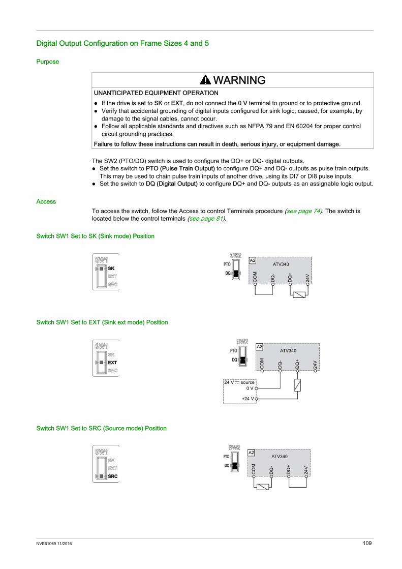
Digital Output Configuration on Frame Sizes 4 and 5
Purpose
The SW2 (PTO/DQ) switch is used to configure the DQ+ or DQ- digital outputs. Set the switch to PTO (Pulse Train Output) to configure DQ+ and DQ- outputs as pulse train outputs.
This may be used to chain pulse train inputs of another drive, using its DI7 or DI8 pulse inputs. Set the switch to DQ (Digital Output) to configure DQ+ and DQ- outputs as an assignable logic output.
AccessTo access the switch, follow the Access to control Terminals procedure (see page 74). The switch is located below the control terminals (see page 81).
Switch SW1 Set to SK (Sink mode) Position
Switch SW1 Set to EXT (Sink ext mode) Position
Switch SW1 Set to SRC (Source mode) Position
WARNINGUNANTICIPATED EQUIPMENT OPERATION If the drive is set to SK or EXT, do not connect the 0 V terminal to ground or to protective ground. Verify that accidental grounding of digital inputs configured for sink logic, caused, for example, by
damage to the signal cables, cannot occur. Follow all applicable standards and directives such as NFPA 79 and EN 60204 for proper control
circuit grounding practices.Failure to follow these instructions can result in death, serious injury, or equipment damage.
NVE61069 11/2016 109

Switch SW1 Set to SRC (Source ext mode) Position
110 NVE61069 11/2016
Safe Torque Off STO Function
Section 4.8Safe Torque Off STO Function
What Is in This Section?This section contains the following topics:
Topic PageSTO Safe Torque Off Wiring Diagram for Frame Sizes 1...3 112STO Safe Torque Off Wiring Diagram for Frame Sizes 4 and 5 113
NVE61069 11/2016 111

STO Safe Torque Off Wiring Diagram for Frame Sizes 1...3
Wiring DiagramAll details related to the STO safety function activation are given in the Embedded Safety Function Manual NVE64143.
When not used for functional safety the STO inputs should be connected to 24V.NOTE: On frame sizes 1, 2 and 3, the 24 V (pin 3) can be disabled using [24V Supply Output] S24V menu.
If the 24 V Supply output is disabled the STO signals must be externally supplied. Refer to the programming manual NVE61643
To avoid to trigger the STO function when switching-on the product, the external power supply must be previously switched on.
CN2 Connector
NOTE: STO_A and STO_B terminals are not factory wired.
112 NVE61069 11/2016
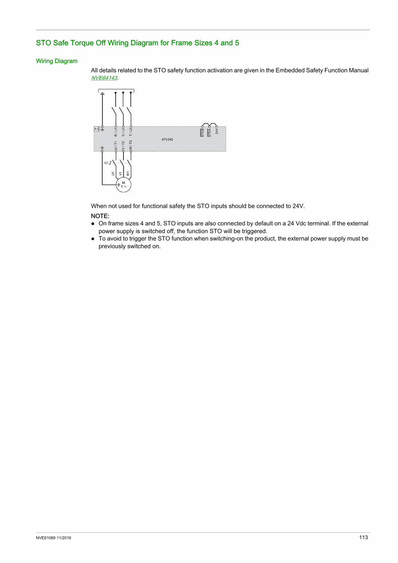
STO Safe Torque Off Wiring Diagram for Frame Sizes 4 and 5
Wiring DiagramAll details related to the STO safety function activation are given in the Embedded Safety Function Manual NVE64143.
When not used for functional safety the STO inputs should be connected to 24V.NOTE: On frame sizes 4 and 5, STO inputs are also connected by default on a 24 Vdc terminal. If the external
power supply is switched off, the function STO will be triggered. To avoid to trigger the STO function when switching-on the product, the external power supply must be
previously switched on.
NVE61069 11/2016 113

Digital Inputs Wiring
Section 4.9Digital Inputs Wiring
What Is in This Section?This section contains the following topics:
Topic PageDigital Inputs Wiring on Frame Sizes 1...3 115Digital Inputs Wiring on Frame Sizes 4 and 5 117
114 NVE61069 11/2016
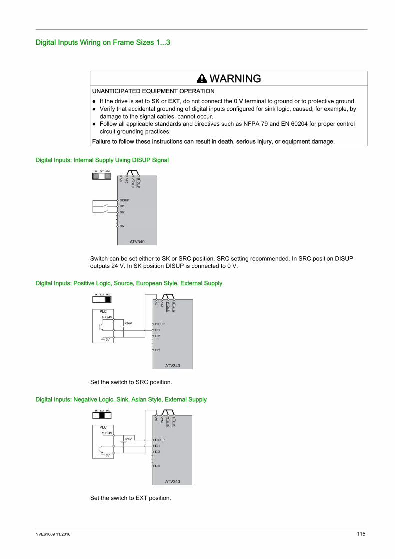
Digital Inputs Wiring on Frame Sizes 1...3
Digital Inputs: Internal Supply Using DISUP Signal
Switch can be set either to SK or SRC position. SRC setting recommended. In SRC position DISUP outputs 24 V. In SK position DISUP is connected to 0 V.
Digital Inputs: Positive Logic, Source, European Style, External Supply
Set the switch to SRC position.
Digital Inputs: Negative Logic, Sink, Asian Style, External Supply
Set the switch to EXT position.
WARNINGUNANTICIPATED EQUIPMENT OPERATION If the drive is set to SK or EXT, do not connect the 0 V terminal to ground or to protective ground. Verify that accidental grounding of digital inputs configured for sink logic, caused, for example, by
damage to the signal cables, cannot occur. Follow all applicable standards and directives such as NFPA 79 and EN 60204 for proper control
circuit grounding practices.Failure to follow these instructions can result in death, serious injury, or equipment damage.
NVE61069 11/2016 115
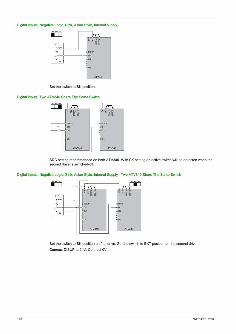
Digital Inputs: Negative Logic, Sink, Asian Style, Internal supply
Set the switch to SK position.
Digital Inputs: Two ATV340 Share The Same Switch
SRC setting recommended on both ATV340. With SK setting an active switch will be detected when the second drive is switched-off.
Digital Inputs: Negative Logic, Sink, Asian Style, Internal Supply - Two ATV340 Share The Same Switch
Set the switch to SK position on first drive. Set the switch to EXT position on the second drive.Connect DISUP to 24V. Connect 0V.
116 NVE61069 11/2016

Digital Inputs Wiring on Frame Sizes 4 and 5
Switch Set to SRC (Source) Position Using the Output Power Supply for the Digital Inputs
Switch Set to SRC (Source) Position and Use of an External Power Supply for the DIs
Switch Set to SK (Sink) Position Using the Output Power Supply for the Digital Inputs
Switch Set to EXT Position Using an External Power Supply for the DIs
NOTE: STO inputs are also connected by default on a 24 Vdc terminal. If the external power supply is switched
off, the function STO will be triggered. To avoid to trigger the STO function when switching-on the product, the external power supply must be
previously switched on.
WARNINGUNANTICIPATED EQUIPMENT OPERATION If the drive is set to SK or EXT, do not connect the 0 V terminal to ground or to protective ground. Verify that accidental grounding of digital inputs configured for sink logic, caused, for example, by
damage to the signal cables, cannot occur. Follow all applicable standards and directives such as NFPA 79 and EN 60204 for proper control
circuit grounding practices.Failure to follow these instructions can result in death, serious injury, or equipment damage.
NVE61069 11/2016 117

Digital Outputs Wiring
Section 4.10Digital Outputs Wiring
What Is in This Section?This section contains the following topics:
Topic PageDigital Outputs Wiring on Frame sizes 1...3 119Digital Outputs Wiring on Frame sizes 4 and 5 119
118 NVE61069 11/2016
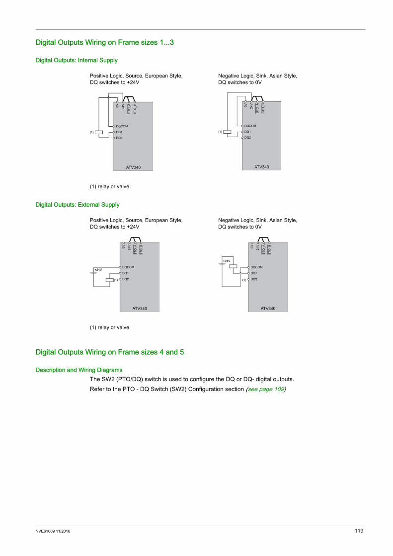
Digital Outputs Wiring on Frame sizes 1...3
Digital Outputs: Internal Supply
Digital Outputs: External Supply
Digital Outputs Wiring on Frame sizes 4 and 5
Description and Wiring DiagramsThe SW2 (PTO/DQ) switch is used to configure the DQ or DQ- digital outputs.Refer to the PTO - DQ Switch (SW2) Configuration section (see page 109)
Positive Logic, Source, European Style, DQ switches to +24V
Negative Logic, Sink, Asian Style, DQ switches to 0V
(1) relay or valve
Positive Logic, Source, European Style, DQ switches to +24V
Negative Logic, Sink, Asian Style, DQ switches to 0V
(1) relay or valve
NVE61069 11/2016 119

Relay Contacts Wiring
Section 4.11Relay Contacts Wiring
Relay Contacts Wiring on Frame Sizes 1...5
Relay Contacts - Holding Brake Connection, Brake With 24 Vdc
If switching inductive load with DC current external overvoltage protection or freewheel diode must be provided.
Frame sizes 1...3 Frame sizes 4 and 5
(1) Freewheel diode(2) Holding brake
120 NVE61069 11/2016
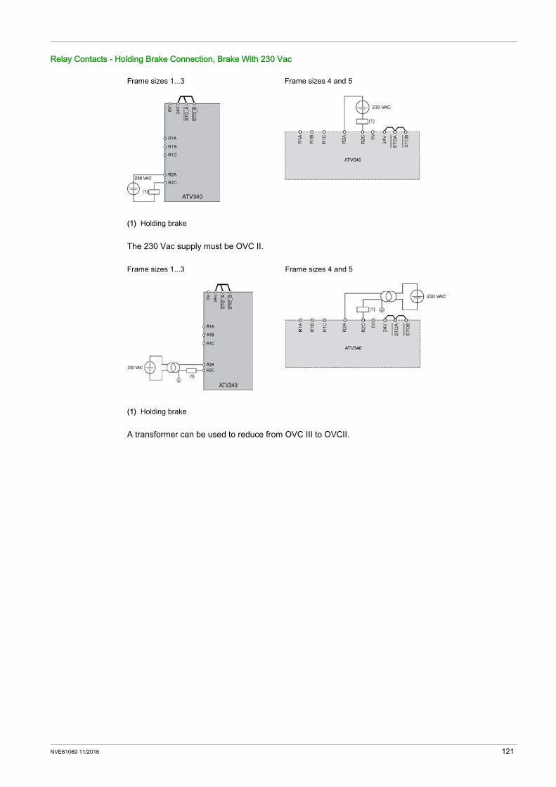
Relay Contacts - Holding Brake Connection, Brake With 230 Vac
The 230 Vac supply must be OVC II.
A transformer can be used to reduce from OVC III to OVCII.
Frame sizes 1...3 Frame sizes 4 and 5
(1) Holding brake
Frame sizes 1...3 Frame sizes 4 and 5
(1) Holding brake
NVE61069 11/2016 121

122 NVE61069 11/2016
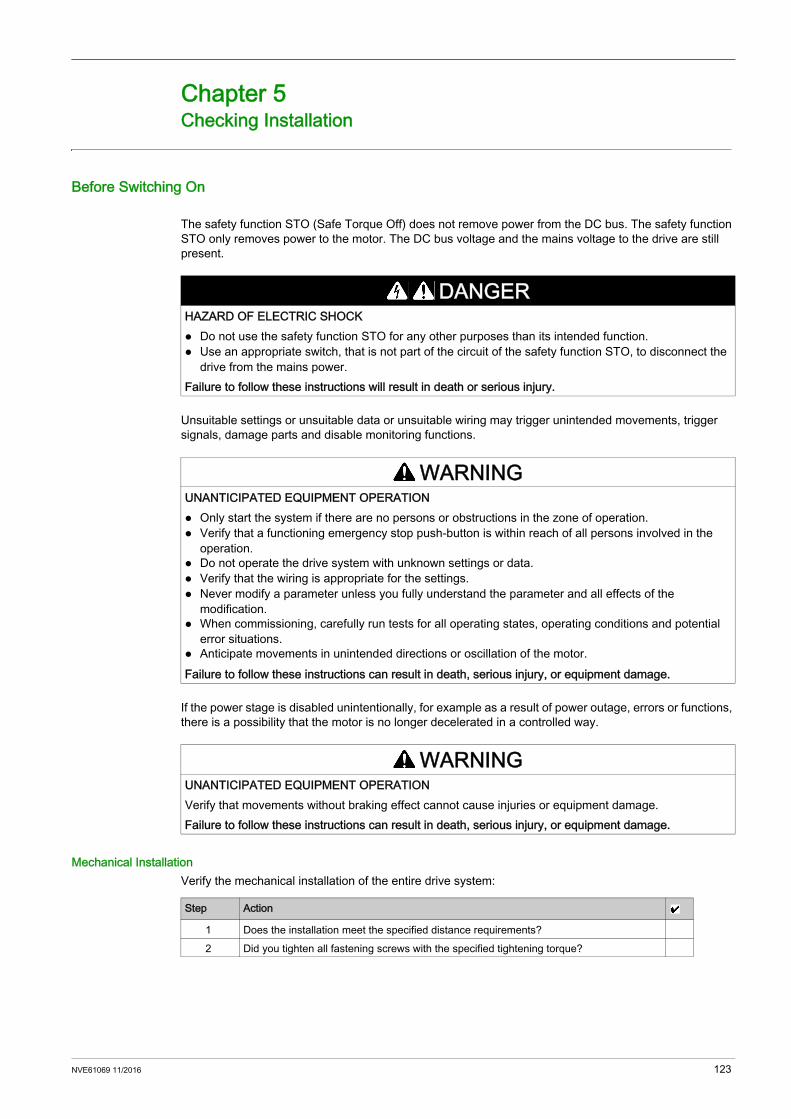
Altivar Machine ATV340
NVE61069 11/2016
Checking Installation
Chapter 5Checking Installation
Before Switching On
The safety function STO (Safe Torque Off) does not remove power from the DC bus. The safety function STO only removes power to the motor. The DC bus voltage and the mains voltage to the drive are still present.
Unsuitable settings or unsuitable data or unsuitable wiring may trigger unintended movements, trigger signals, damage parts and disable monitoring functions.
If the power stage is disabled unintentionally, for example as a result of power outage, errors or functions, there is a possibility that the motor is no longer decelerated in a controlled way.
Mechanical InstallationVerify the mechanical installation of the entire drive system:
DANGERHAZARD OF ELECTRIC SHOCK Do not use the safety function STO for any other purposes than its intended function. Use an appropriate switch, that is not part of the circuit of the safety function STO, to disconnect the
drive from the mains power.Failure to follow these instructions will result in death or serious injury.
WARNINGUNANTICIPATED EQUIPMENT OPERATION Only start the system if there are no persons or obstructions in the zone of operation. Verify that a functioning emergency stop push-button is within reach of all persons involved in the
operation. Do not operate the drive system with unknown settings or data. Verify that the wiring is appropriate for the settings. Never modify a parameter unless you fully understand the parameter and all effects of the
modification. When commissioning, carefully run tests for all operating states, operating conditions and potential
error situations. Anticipate movements in unintended directions or oscillation of the motor.Failure to follow these instructions can result in death, serious injury, or equipment damage.
WARNINGUNANTICIPATED EQUIPMENT OPERATIONVerify that movements without braking effect cannot cause injuries or equipment damage.Failure to follow these instructions can result in death, serious injury, or equipment damage.
Step Action
1 Does the installation meet the specified distance requirements?2 Did you tighten all fastening screws with the specified tightening torque?
NVE61069 11/2016 123

Electrical installationVerify the electrical connections and the cabling:
Covers And SealsVerify that all devices, doors and covers of cabinet are properly installed to meet the required degree of protection.
Step Action
1 Did you connect all protective ground conductors?2 Do all fuses and circuit breaker have the correct rating; are the fuses of the specified type?
(refer to the information provided in the ATV340 Catalog or in the Getting Started Annex (SCCR) reference: NVE37641).
3 Did you connect or insulate all wires at the cable ends?4 Did you properly connect and install all cables and connectors?5 Did you properly connect the signal wires?6 Are the required shield connections EMC-compliant?7 Did you take all measures for EMC compliance?
124 NVE61069 11/2016
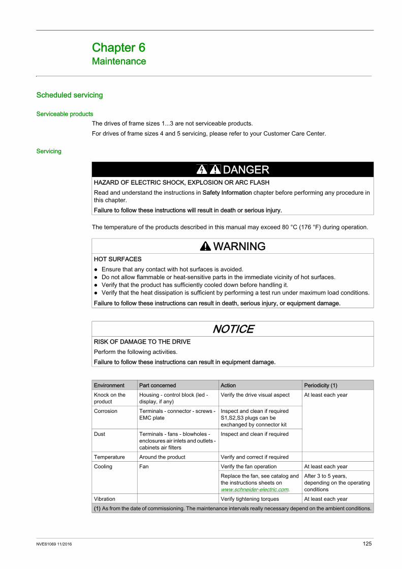
Altivar Machine ATV340
NVE61069 11/2016
Maintenance
Chapter 6Maintenance
Scheduled servicing
Serviceable productsThe drives of frame sizes 1...3 are not serviceable products. For drives of frame sizes 4 and 5 servicing, please refer to your Customer Care Center.
Servicing
The temperature of the products described in this manual may exceed 80 °C (176 °F) during operation.
DANGERHAZARD OF ELECTRIC SHOCK, EXPLOSION OR ARC FLASHRead and understand the instructions in Safety Information chapter before performing any procedure in this chapter.Failure to follow these instructions will result in death or serious injury.
WARNINGHOT SURFACES Ensure that any contact with hot surfaces is avoided. Do not allow flammable or heat-sensitive parts in the immediate vicinity of hot surfaces. Verify that the product has sufficiently cooled down before handling it. Verify that the heat dissipation is sufficient by performing a test run under maximum load conditions.Failure to follow these instructions can result in death, serious injury, or equipment damage.
NOTICERISK OF DAMAGE TO THE DRIVEPerform the following activities.Failure to follow these instructions can result in equipment damage.
Environment Part concerned Action Periodicity (1)Knock on the product
Housing - control block (led - display, if any)
Verify the drive visual aspect At least each year
Corrosion Terminals - connector - screws - EMC plate
Inspect and clean if required S1,S2,S3 plugs can be exchanged by connector kit
Dust Terminals - fans - blowholes - enclosures air inlets and outlets - cabinets air filters
Inspect and clean if required
Temperature Around the product Verify and correct if required Cooling Fan Verify the fan operation At least each year
Replace the fan, see catalog and the instructions sheets on www.schneider-electric.com.
After 3 to 5 years, depending on the operating conditions
Vibration Verify tightening torques At least each year (1) As from the date of commissioning. The maintenance intervals really necessary depend on the ambient conditions.
NVE61069 11/2016 125
Fans may continue to run for a certain period of time even after power to the product has been disconnected.
Diagnostic And TroubleshootingRefer to the Programming manual NVE61643 available on www.schneider-electric.com.
Spares and repairsServiceable product. Please refer to your Customer Care Center.Fan replacement: It is possible to order a new fan. See the catalog for part numbers on www.schneider-electric.com.
Long time storageIf the drive was not connected to mains for an extended period of time, the capacitors must be restored to their full performance before the motor is started.
If the specified procedure cannot be performed without a Run command because of internal mains contactor control, perform this procedure with the power stage enabled, but the motor being at standstill so that there is no appreciable mains current in the capacitors.
CAUTIONRUNNING FANSVerify that fans have come to a complete standstill before handling them.Failure to follow these instructions can result in injury or equipment damage.
NOTICEREDUCED CAPACITOR PERFORMANCE Apply mains voltage to the drive for one hour before starting the motor if the drive has not been
connected to mains for the following periods of time: 12 months at a maximum storage temperature of +50°C (+122°F) 24 months at a maximum storage temperature of +45°C (+113°F) 36 months at a maximum storage temperature of +40°C (+104°F)
Verify that no Run command can be applied before the period of one hour has elapsed. Verify the date of manufacture if the drive is commissioned for the first time and run the specified
procedure if the date of manufacture is more than 12 months in the past.Failure to follow these instructions can result in equipment damage.
126 NVE61069 11/2016

Altivar Machine ATV340GlossaryNVE61069 11/2016
Glossary
EError
Discrepancy between a detected (computed, measured, or signaled) value or condition and the specified or theoretically correct value or condition.
FFactory setting
Factory settings when the product is shipped
FaultFault is an operating state. If the monitoring functions detect an error, a transition to this operating state is triggered, depending on the error class. A "Fault reset" is required to exit this operating state after the cause of the detected error has been removed. Further information can be found in the pertinent standards such as IEC 61800-7, ODVA Common Industrial Protocol (CIP).
Fault ResetA function used to restore the drive to an operational state after a detected error is cleared by removing the cause of the error so that the error is no longer active.
PPELV
Protective Extra Low Voltage, low voltage with isolation. For more information: IEC 60364-4-41
PLCProgrammable logic controller
Power stageThe power stage controls the motor. The power stage generates current for controlling the motor.
RREACh
Registration, Evaluation, Authorisation and restriction of Chemicals regulation
RoHSRestriction of Hazardous Substances
WWarning
If the term is used outside the context of safety instructions, a warning alerts to a potential problem that was detected by a monitoring function. A warning does not cause a transition of the operating state.
NVE61069 11/2016 127

Glossary
128 NVE61069 11/2016

ATV340_Installation_manual_EN_NVE61069_01
11/2016


![Altivar Machine ATV320 - Schneider ElectricINPUTS / OUTPUTS CFG] ... REFERENCE MEMORIZING ... Use only electrically insulated tools.](https://static.documents.pub/doc/80x56/5aff3e787f8b9a864d902bcd/altivar-machine-atv320-schneider-inputs-outputs-cfg-reference-memorizing.jpg)


