The planning, assembly and putting into operation of a solar energy plant must be undertaken, exclusively, by qualified personnel. Unprofessional execution of the project can result in damage to the plant and place people in danger.
Safety instructions
Risk of falling! There is a risk of falling when working on the roof as well as when ascending and descending the building. Accident prevention regulations must be observed and appropriate safety equipment must be used.
Risk of injury! Objects falling from the roof can cause injury to people. The danger area around the installation site must be sealed off and people close to this area must be warned.
Risk of breakage! PV modules can be damaged if stepped upon.
Risk of electric shock! The mounting and maintenance of the PV modules must be carried out by qualified specialists only. Please observe the safety regulations issued by the PV module manufacturer!
The system must be built exclusively with the ballast specified in the structural analysis for superimposed loads. You will receive these from Schletter along with the plant design. Alternatively the data can be obtained directly in the “Downloads” area on our website: www.schletter.eu
The required distances to the roof edges must be maintained.
Mounting information
On roofs with substrate covering or gravel, it has to be safeguarded that the contact area between the continuous beams and the subsurface is sufficiently skid-proof.
AluGrid is not recommended for roofs with a pitch of more than 10 degrees.
If the roof of the roof sealing is very uneven, compensatory measures may have to be taken in order to safeguard an evenly distrib-uted load transfer.
The maximum size of array depends on the type of roof. On membrane roofs, a module array size must not exceed 10m in any direction; on concrete roofs the maximum permissible size of array is up to 30m.
Make sure that the sealing of the flat roof and the rubber underlays are compatible.
For reasons of structural safety, at least two module rows should be interconnected. If this is not possible, please consult our technical advisers.
The partial pressure on the surfaces on the roof cladding under the continuous beams must not exceed die admissible distributed surface load.
The distributed load must not exceed the excess load-bearing capacity of the building!
Extending continuous beams• Continuous beams can be extended
if required.• Insert an AluGrid connector into two
rails and fasten it with two self-drilling screws to each rail end.
Tools:Power screwdriver with 8 mm bit
Mounting of the rubber underlays• Press the rubber underlay into the
underside of the profile (rail).• As an alternative, strips of the surface
protection mat can be laid under the continuous beams designed for that purpose.
• If the rain water runs at right angle to the continuous beam, short surface protection mat strips are to be laid at certain distances so that the rain wa-ter can drain off. The specific distance between these protection mat strips is determined on the basis of the local amount of precipitation.
Alignment of the continuous beams• When the continuous beams are
equipped with the rubber underlays, they are arranged parallel to each other and vertically to the planned module rows.
• Distance between the beams: Module length plus 20 mm (± 5mm)
Anti-slip device• On inclined roofs, module arrays must
be secured against sliding bya) horizontal fastening or b) coupling two opposite continuous beams using a tension connector at the ridge. For this purpose, fasten the connectors to both beams from above with four screws each.
• Roof parapets can also serve to pre-vent sliding. A correct fastening and structural safety are compulsory.
Mounting of the module support• Appropriate shade distances and / or
row distances must be observed.• Let the module bearings snap into
the appropriate positions - see the dimensional drawing at the bottom of this page.
Mounting of the Windsafe metal sheets• The distances between the Windsafe
metal sheet and the front bearing - depending on the module size - can be looked up in the dimensional drawing at the bottom of this page.
• To mount the first Windsafe metal sheet, place the fastening clamp into the lateral cut-out of the metal sheet (left side from the rear) and let it snap into the continuous beam below.
• Put the Windsafe sheet for the next module onto the previously mounted sheet. Place the slots above each oth-er in order to be able to lead through the fastening clamp. Which slots are to be used depends on the length of the modules. It may be helpful to carry out a test assembly before.
• Clamp both Windsafe sheets with the fastening clamp to the continuous beam.
• Repeat the two previous steps for the subsequent metal sheets.
• Clamp the last metal sheet at the end.• Mount the subsequent rows in the
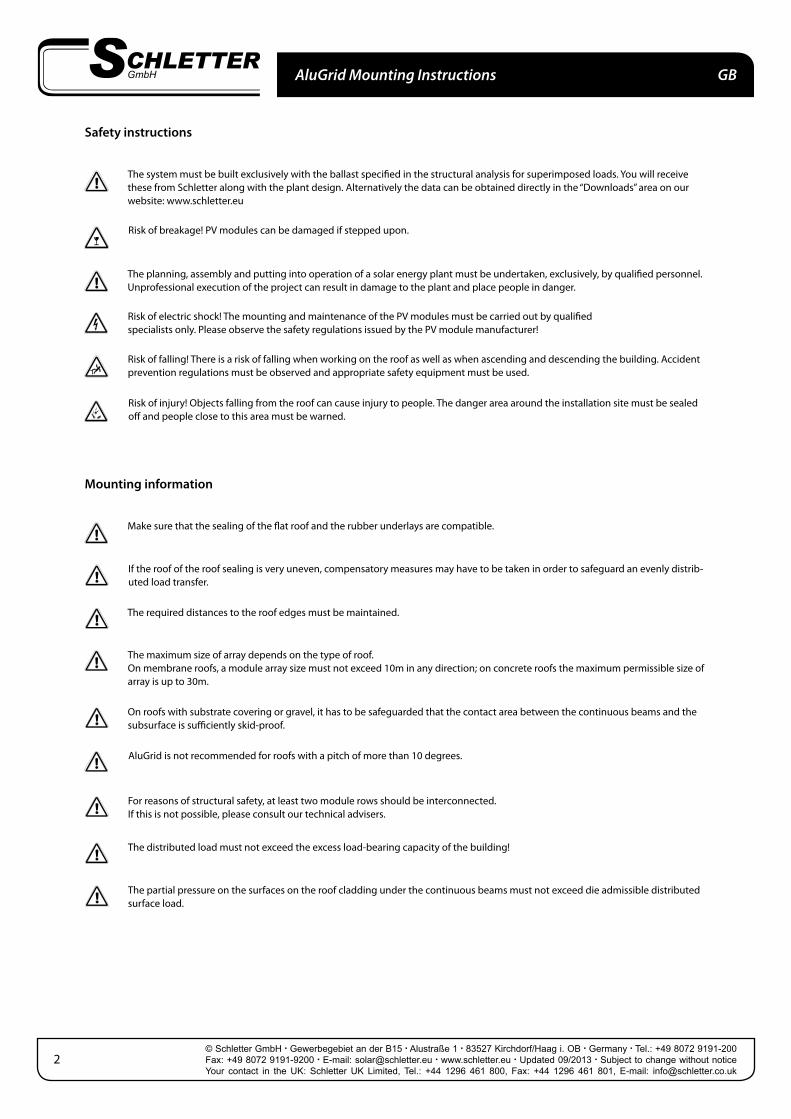
If heavier ballasts are required for structural reasons, for example in corner zones, additional load trays are to be attached. Ballast trays from the system variant AluGrid100 can be used for this purpose. These trays can be installed beneath the modules or in an area of shading clearance, for example. No further areas of shade should be created by adding trays, however.
• Arrange the load trays as required• Overlap the metal sheets as shown in
the picture on the right.• Fit the end plate into the last cut-out.• Place the fastening clamps into the
lateral cut-outs of the metal sheet and let it snap into the continuous beams below.
• Maximum permissible ballast per tray: 100 kg
Heavy snow loads
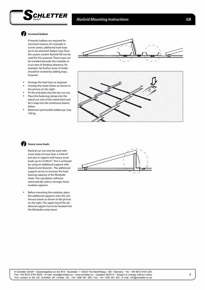
AluGrid can not only be used with snow loads of more than 2.4 kN/m², but also in regions with heavy snow loads up to 5.4 kN/m². This is achieved by using an additional support with AluGrid and AluGrid+. The additional support serves to increase the load-bearing capacity of the Windsafe sheet. The calculation software automatically selects stronger lower module supports.
• Before mounting the modules, place the additional supports onto the con-tinuous beam as shown in the picture on the right. The upper lug of the ad-ditional support has to be hooked into the Windsafe metal sheet.
Module mounting• Position the lower edge of the module
on the module bearings. • Connect the module cables as required.• Press the cables into the clips.• Position the upper edge of the
module on the bearings of the the Windsafe sheets.
Prepare the cabling• Place the cable clips into the intended
slots in the Windsafe sheet. (usually 2 clips in the back side and 1 Proklip-U in the folded side).
Preparation of the AluGrid pliers• Set the AluGrid pliers according to the
size of the modules using the setting screw.
Make sure that the jaws are movable!
Please make sure that the clamp slightly reaches over the edge that is to be clamped when the pliers are strained. Due to tool wear, produc-tion tolerances of the module frames, etc., a readjustment may be required. If the clamp does not fit tightly enough, this will have a bad effect on the clamping and thus has to be absolutely avoided.
Fastening of the modules• Span the module clamps using the
AluGrid pliers.• Press the module onto the bearing.• Hook in the module clamp into the
bearing - first at the bottom and then at the top.
• Clamp the module clamp onto the module frame by releasing the pliers.
• Fasten each module with two clamps at the bottom and two at the top.
11
Securing of the modules• Bend the lug of the Windsafe metal
sheets around the module frame us-ing your finger.
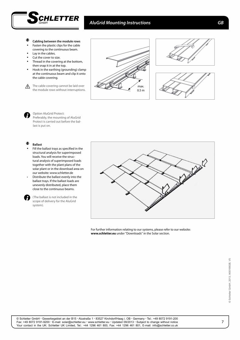
Cabling between the module rows• Fasten the plastic clips for the cable
covering to the continuous beam.• Lay in the cables.• Cut the cover to size.• Thread in the covering at the bottom,
then snap it in at the top.• Hook in the earthing (grounding) clamp
at the continuous beam and clip it onto the cable covering.
The cable covering cannot be laid over the module rows without interruptions.
Ballast• Fill the ballast trays as specified in the
structural analysis for superimposed loads. You will receive the struc-tural analysis of superimposed loads together with the plant plans of the solar plant or in the download area on our website: www.schletter.de
• Distribute the ballast evenly into the ballast trays. If the ballast loads are unevenly distributed, place them close to the continuous beams.
(The ballast is not included in the scope of delivery for the AluGrid system).
For further information relating to our systems, please refer to our website: www.schletter.eu under "Downloads" in the Solar section.