Page 1
Delft University of Technology
Performance improvement by alumina coatings on Y3Al5O12Ce3+ phosphor powder deposited using atomic layer deposition in a fluidized bed reactorZhou, Zhi; Zhou, Nan; Lu, Xiangyang; ten Kate, Melvin; Valdesueiro Gonzalez, David; van Ommen, Ruud;Hintzen, BertDOI10.1039/c6ra12983hPublication date2016Document VersionAccepted author manuscriptPublished inRSC Advances
Citation (APA)Zhou, Z., Zhou, N., Lu, X., Kate, M. T., Valdesueiro Gonzalez, D., van Ommen, J. R., & Hintzen, H. T.(2016). Performance improvement by alumina coatings on Y3Al5O12: Ce3+ phosphor powder depositedusing atomic layer deposition in a fluidized bed reactor. RSC Advances, 6(80), 76454-76462.https://doi.org/10.1039/c6ra12983hImportant noteTo cite this publication, please use the final published version (if applicable).Please check the document version above.
CopyrightOther than for strictly personal use, it is not permitted to download, forward or distribute the text or part of it, without the consentof the author(s) and/or copyright holder(s), unless the work is under an open content license such as Creative Commons.
Takedown policyPlease contact us and provide details if you believe this document breaches copyrights.We will remove access to the work immediately and investigate your claim.
This work is downloaded from Delft University of Technology.For technical reasons the number of authors shown on this cover page is limited to a maximum of 10.
Page 2
Performance improvement by alumina coatings on 1
Y3Al5O12:Ce3+
phosphor powder deposited using Atomic 2
Layer Deposition in a fluidized bed reactor 3
4
Zhi Zhou1, Nan Zhou*
1, Xiangyang Lu*
2, Melvin ten Kate
3, David Valdesueiro
4, J. Ruud van 5
Ommen3, H.T. (Bert) Hintzen
46
7
1 Science College of Hunan Agricultural University, Changsha 410128, China 8
2 College of Bioscience and Biotechnology, Hunan Agricultural University, Changsha 410128, 9
China 10
3 Department of Chemical Engineering, Delft University of Technology, Van der Maasweg 9, 11
2629 HZ Delft, The Netherlands 12
4 Group Luminescent Materials, Section Fundamental Aspects of Materials and Energy, Faculty of 13
Applied Sciences, Delft University of Technology, The Netherlands 14
15
Corresponding authors: Dr. Nan Zhou, Email: [email protected] ; 16
Prof. Xiangyang Lu, Email: [email protected] . 17
18
19
Abstract: 20
To improve the thermal stability, Al2O3 has been successfully coated on a Y3Al5O12: 21
Ce3+
(YAG:Ce) phosphor powder host by using the Atomic Layer Deposition (ALD)22
approach in a fluidized bed reactor. Transmission Electron Microscopy (TEM) and 23
Energy Dispersive X-ray spectroscopy (EDX) analysis indicate that coating an Al2O3 24
thin layer by ALD is highly feasible. The luminescence properties (such as excitation 25
and emission as well as quantum efficiency and UV-absorption of the coated YAG:Ce 26
phosphor) were systematically analysed, with the further examination of the thermal 27
resistance characteristics. The Al2O3 thin layer coating with precisely controlled 28
thickness by ALD can obviously improve theluminescence intensity and greatly 29
enhances the thermal stability of the YAG:Ce phosphor. It is suggested that the 30
alumina coating with tailoring thickness seems not only to act like a barrier to 31
decrease the thermal quenching, but also as a great help to promote the light 32
absorption and transfer. 33
34
Key words: Atomic Layer Deposition (ALD), fluidized bed reactor, YAG:Ce, 35
phosphor, powder coating, thermal stability. 36
37
38
39
40
This is an Accepted Author Manuscript of an article published by RSC in the journal RSC Advances, available online: http://dx.doi.org/10.1039/C6RA12983H
Page 3
1 Introduction 41
Inorganic luminescent materials, or phosphors, are commonly utilized for many 42
applications such as monitors, fluorescent lamps, plasma displays, X-ray amplifier 43
screens, Light Emitting Diodes (LEDs), and electroluminescent displays due to their 44
cathodo-, photo-, X-ray- or electro-luminescence properties1-3
. However, the 45
instability of the phosphors against temperature, oxygen, water, acids, etc. remains a 46
problem, which significantly hinders theirprocessing, storage as well as the 47
applications2. 48
Coating a phosphor with a protective layer has been proved to be an efficient 49
approach to protect a phosphor from environmental attack4-12
. Thus, several 50
techniques have been explored to deposit coating layers on phosphor. Including 1) 51
solid-state techniques such as rolling, milling, grinding of mixtures of phosphor 52
powders with the precursor, followed by drying or a heat treatment if necessary; 2) 53
liquid-phase techniques such as sol-gel4-6
, emulsion7, hetero-coagulation
8, and 54
precipitation9; and 3) gas-phase techniques such as Chemical Vapor Deposition 55
(CVD)10
, Pulsed Laser Deposition (PLD)11
, and Atomic Layer Deposition (ALD)12, 13
. 56
However, most of the conventional coating methods suffer from inhomogeneous 57
and/or ununiformed coating layer deposition, which will has a negative effect on the 58
optical properties6. Therefore, a closed thin film coating method is needed in order to 59
protect phosphor particles while maintaining (or even improving) the optical 60
properties. 61
ALD is well known for depositing thin films on a flat surface, but with the 62
combination of a fluidized bed reactor, it can also be used for coating micro and 63
nano-sized powders14
. In such a fluidized bed reactor the particles are suspended in an 64
upward gas flow so that good contact between gas and particles is ensured. Besides 65
thin but nevertheless closed coating, another main advantage of ALD is that the 66
thickness of a coated layer can be precisely designed by strictly controlling the 67
number of ALD cycles. Thus, ALD can supply a uniform coating even on high surface 68
area materials allowing a variation of thickness at an atomic resolution, all of which 69
benefits ALD as a suitable method for homogeneous ultrathin layer deposition15
. Li et 70
al.16
successfully deposited a 15 nm TiO2 thin film on Cu2O-based photocathodes 71
through ALD method after ALD coating of an appropriate 20 nm bufferlayer of 72
Ga2O3 on Cu2O microcrystals. The high thermal resistance of Ga2O3 allowed for the 73
double coating at relatively high temperatures, resulting in a better photo-voltage of 74
the whole active cathode. A thin 1.2 nm TiO2 coating was performed by ALD on 75
cobalt particles to prevent both leaching and sintering during aqueous-phase reactions. 76
The TiO2/Co/TiO2 compositeshowed a high catalysis activity foraqueous-phase 77
hydrogenation reactions with excellent stability17
. All above demonstrate that ALD 78
techniques can produce continuous, pinhole-free oxide films with 79
Angstrom-level-controllable thickness. Especially within a fluidized bed reactor, ALD 80
shows high potential for depositing a protective thin layer coating on a phosphor 81
particle without hurting the optical properties. 82
Many kinds of the oxides, such as Al2O318-20
, SiO221, 22
, TiO223, 24
, ZnO25, 26
, and 83
ZrO27
have been used as coating material in ALD processes. Among them, Al2O3 is 84
Page 4
considered to be a promising coating agent to enhance the resistance of the coated 85
materials. For example, the capacity fading of LiMn2O4 spinel as a battery material 86
can be significantly reduced due to Al2O3 coating and consistent discharge curves 87
were found even after 50 charging/discharging cycles at an elevated temperature of 55℃88 28
. Ultrathin compact Al2O3 layers deposited by ALD were also utilized to improve 89
the ambient stability of quantum dot films29
and organic-inorganic perovskite solar 90
cells20
. The results demonstrate that the stability of the solar cell against humidity was 91
greatly enhanced without an obvious reduction in efficiency. Besides, Al2O3 92
demonstrates a unique affinity to a large variety of substrate14
, together with its low 93
deposition temperature, led to the judgments that depositing Al2O3 as a coating via 94
ALD in a fluidized bed reactoris a promising way to increase resistance against 95
outside attacks resisted for phosphor materials like Y3Al5O12: Ce3+
. 96
Y3Al5O12: Ce3+
(the trivalent cerium activated Yttrium Aluminate phosphor with 97
Garnet structure, referred to as YAG:Ce), is a well-known luminescent material which 98
has been broadly applied in the fields of flying spot scanner tubes in the past and 99
white LED (WLED) devices nowadays. However, like most of the luminescence 100
phosphors, YAG:Ce also suffers from the thermal instability, especially when used in 101
practical WLED devices3. In this work, YAG:Ce phosphor powderis employed as 102
model material to study the improvement of the thermal stability by Al2O3 coating 103
through ALD process performed in a fluidized bed reactor under atmospheric pressure. 104
The impact of ALD cycle numbers on the thickness of the Al2O3 layer is investigated, 105
as well as the thermal and optical performance of YAG:Ce phosphor. It will be shown 106
that the ALD method with a fluidized bed reactor using alumina as oxide coating 107
materials could be a feasible way for the ultrathin film coating of YAG:Ce phosphors 108
and apply a protective barrier for improving thermal resistance while maintaining the 109
optical properties. 110
111
2 Experimental 112
2.1 Starting materials 113
The YAG:Ce phosphor particles were obtained from Steady (Hunan Steady New 114
Materials Company, China), which have a regular spherical morphology with highly 115
concentrated particle size distribution between 6-15 micrometers. 116
Tri-Methyl-Aluminium (TMA, semiconductor grade) was supplied by Akzo-Nobel 117
HPMO in a 400mL VER-400 bubbler. The gas washers were filled with Kaydol oil, 118
supplied by Sonneborn (Haarlem). 119
120
2.2 Sample preparation by ALD coating process in a fluidized bed reactor 121
A schematic illustration of the ALD set-up with a fluidized bed reactor for the 122
alumina coating on YAG:Ce particle is shown in Fig. 1. From left to right, Part A is a 123
nitrogen gas tank supplying a nitrogen flow. Part B is a bubbler filled with liquid 124
TMA, through which nitrogen is bubbled to obtain a nitrogen flow with TMA vapor. 125
Part C is a gas bottle filled with an N2/O2 mixture (80%/20%). Part D is the Fluidized 126
Bed Reactor (FBR), the main part of which is a glass column with 26 mm in internal 127
diameter and 500 mm in length. Only less than one third volume of the column can be 128
Page 5
filled with certain amount (100-120g) of phosphor particles, in order to guarantee 129
enough space for the particles during fluidizing. The FBR is placed on a vibration 130
table driven by two vibro-motors (Part E), which can produce a low amplitude 131
vibration at a set frequency of 45 Hz to assist fluidization. The coating experiments 132
were carried out at room temperature of about 25◦C. And Part F represents the gas 133
washers to neutralize TMA that might be released from the reactor. 134
Generally, one ALD cycle can be divided into four process steps: (1) TMA 135
exposure, (2) purge with nitrogen gas, (3) oxygen exposure and (4) purge with 136
nitrogen gas again. To begin with the whole ALD set needs to be purged with nitrogen 137
for about 20 min before starting the first ALD cycle. For the first step of TMA 138
exposure, nitrogen was purged through the reactant bubbler (Part B) filled with TMA 139
and making a gas stream for carrying the reactant into the FBR (Part D) with a flow 140
rate of 0.6 L/min (0.02 m/s superficial gas velocity). Subsequently, N2 was pumped 141
into the reactor to carry away the redundant TMA at the second step. After that, 142
synthetic air was pumped into the reactor to oxidize TMA and form the Al2O3 coating. 143
Finally, the extra oxygen was blown away by N2 and then a new cycle can be started. 144
Duration of each step has been optimized as 3, 10, 3 and 10 minutes, respectively. 145
146
147
Fig. 1 Schematic illustration of the ALD set-up and process: (A) nitrogen gas tank; (B) and (C) 148
reactant tanks; (D) Fluidized Bed Reactor (FBR); (E) vibro-motors; (F) gas washers. 149
Effluent gases from the reactor were led through a double set of gas washers 150
(Part F) filled with mineral oil. The gas streams containing TMA was led through 151
separate gas washers to prevent reaction in the washers. Any TMA absorbed in the gas 152
washers was neutralized after the experiment. The effluent from the gas washers was 153
filtered using Pall Kleenpak pharmaceutical grade sterilizing filters to capture 154
elutriated nanoparticles. The pressure at the outlet was atmospheric, meaning that the 155
pressure in the column is slightly above atmospheric pressure. This is uncommon, as 156
Page 6
most ALD is carried out at vacuum. More details about the reactor can be found in our 157
previous work14
. 158
159
2.3 Characterization 160
The crystalline phases and compositions of the prepared samples were examined 161
by X-ray diffractometry (XRD) using a Bruker D4 Endeavor apparatus with a 162
graphite- monochromatized Cu Ka radiation at 40 kV and 40 mA. The 2θ ranges of all 163
the data sets are from 10 to 80◦ using step scan with a step size of 0.02
◦ in 2θ and a 164
counting time of 1s per step.The micro-morphology and elemental mapping of the 165
samples were observed by using a JEOL/EO6500F Scanning Electron Microscope 166
(SEM) combined with Energy Dispersive X-ray spectroscopy (EDX), the voltage of 167
the EDX is 10KV and the spot size is 69 μm. Cross section SEM combined with EDX 168
was carried out on a FEI Nova Nano SEM for the Al2O3 coated samples, besides the 169
normal electric-beam for SEM, the equipment has anextra ion-beam for cut and mill 170
the target samples. Moreover, Transmission Electron Microscopy (TEM) analysis was 171
performed with an HRTEM JEOL 2010 high-resolution transmission electron 172
microscope in combination with EDX spectroscopy and a GATAN digital micrograph 173
with a slow-scan CCD camera. 174
175
2.4 Optical properties 176
A Perkin Elmer LS 50B spectrophotometer equipped with a Xe flash lamp as the 177
excitation source was used to conduct diffuse reflectance and photoluminescence (PL) 178
measurements. The reflection spectra were calibrated with the reflection of black felt 179
(reflection 3%) and white barium sulfate (BaSO4, reflection ~100%) in the 180
wavelength region of 230-700 nm. The excitation and emission slits were set at 15 nm. 181
All measurements were performed at room temperature. 182
The temperature dependent luminescence properties were measured by 183
home-built equipment. The emission spectra were measured in air with the 184
temperature increased from 300K to 600K. The emission spectrum was recorded from 185
480 nm to 700 nm with an excitation wavelength of 460 nm came from a Xe flash 186
lamp. The sample chamber was heated up with a rate of 10 K/min. The equipment 187
was maintained for extra 5 min before each measurement to hold a constant 188
temperature. The excitation and emission slits were set at 5 nm. Excitation spectra 189
were automatically corrected for the variation in the lamp intensity by a second 190
photomultiplier and a beam-splitter. All the spectra were measured with a scan speed 191
of 100 nm/min. 192
193
3 Results and discussion 194
3.1 Phase composition 195
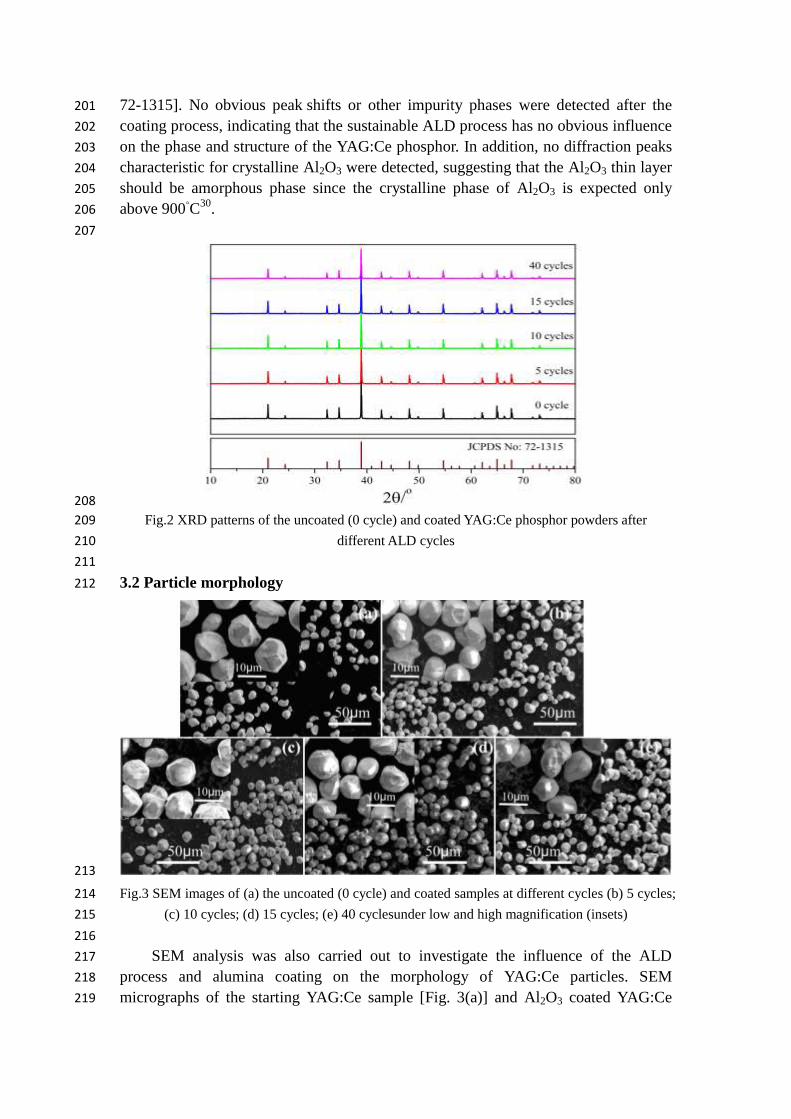
To study the impact of the ALD process on the phase composition of the selected 196
phosphor material, uncoated and Al2O3 coated Ce-doped YAG phosphor powders 197
were examined by XRD. As shown in Fig. 2, the diffraction peaks of all obtained 198
materials with or without coating are corresponding to Y3Al5O12 with the garnet 199
structure (YAG) [Joint Committee on Powder Diffraction Standards (JCPDS) card No. 200
Page 7
72-1315]. No obvious peak shifts or other impurity phases were detected after the 201
coating process, indicating that the sustainable ALD process has no obvious influence 202
on the phase and structure of the YAG:Ce phosphor. In addition, no diffraction peaks 203
characteristic for crystalline Al2O3 were detected, suggesting that the Al2O3 thin layer 204
should be amorphous phase since the crystalline phase of Al2O3 is expected only 205
above 900◦C
30. 206
207
208
Fig.2 XRD patterns of the uncoated (0 cycle) and coated YAG:Ce phosphor powders after 209
different ALD cycles 210
211
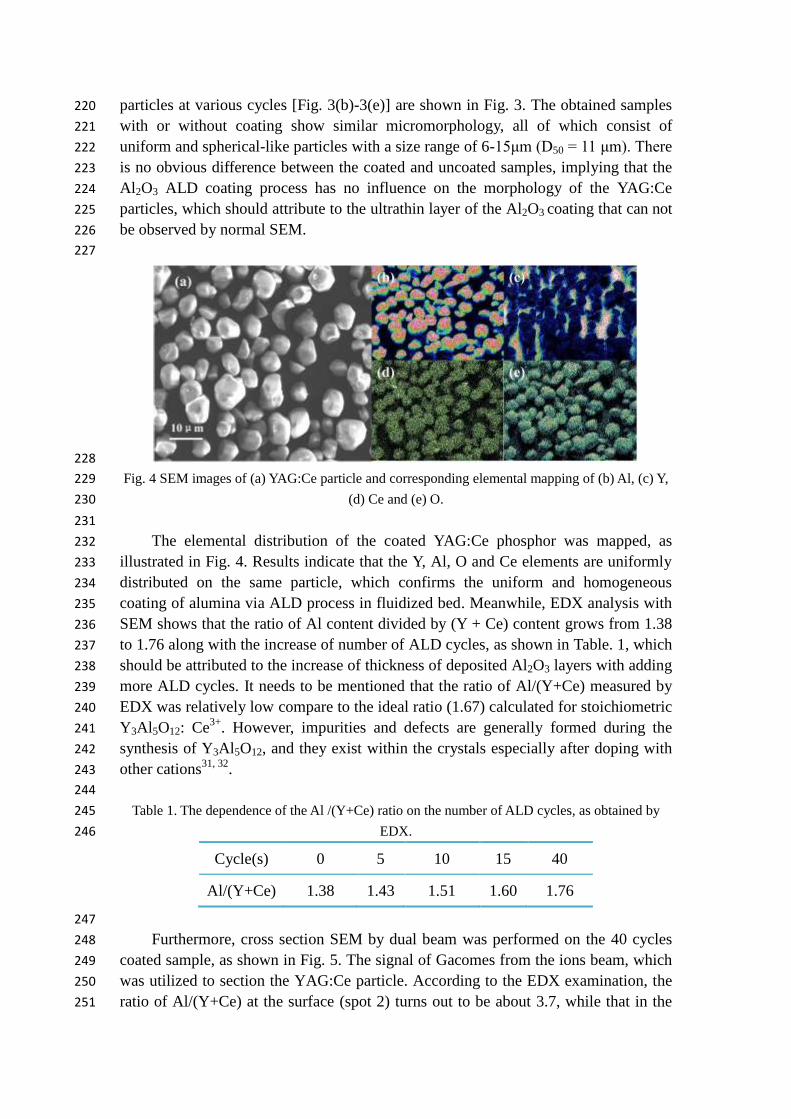
3.2 Particle morphology 212
213
Fig.3 SEM images of (a) the uncoated (0 cycle) and coated samples at different cycles (b) 5 cycles; 214
(c) 10 cycles; (d) 15 cycles; (e) 40 cyclesunder low and high magnification (insets) 215
216
SEM analysis was also carried out to investigate the influence of the ALD 217
process and alumina coating on the morphology of YAG:Ce particles. SEM 218
micrographs of the starting YAG:Ce sample [Fig. 3(a)] and Al2O3 coated YAG:Ce 219
Page 8
particles at various cycles [Fig. 3(b)-3(e)] are shown in Fig. 3. The obtained samples 220
with or without coating show similar micromorphology, all of which consist of 221
uniform and spherical-like particles with a size range of 6-15μm (D50 = 11 μm). There 222
is no obvious difference between the coated and uncoated samples, implying that the 223
Al2O3 ALD coating process has no influence on the morphology of the YAG:Ce 224
particles, which should attribute to the ultrathin layer of the Al2O3 coating that can not 225
be observed by normal SEM. 226
227
228
Fig. 4 SEM images of (a) YAG:Ce particle and corresponding elemental mapping of (b) Al, (c) Y, 229
(d) Ce and (e) O. 230
231
The elemental distribution of the coated YAG:Ce phosphor was mapped, as 232
illustrated in Fig. 4. Results indicate that the Y, Al, O and Ce elements are uniformly 233
distributed on the same particle, which confirms the uniform and homogeneous 234
coating of alumina via ALD process in fluidized bed. Meanwhile, EDX analysis with 235
SEM shows that the ratio of Al content divided by (Y + Ce) content grows from 1.38 236
to 1.76 along with the increase of number of ALD cycles, as shown in Table. 1, which 237
should be attributed to the increase of thickness of deposited Al2O3 layers with adding 238
more ALD cycles. It needs to be mentioned that the ratio of Al/(Y+Ce) measured by 239
EDX was relatively low compare to the ideal ratio (1.67) calculated for stoichiometric 240
Y3Al5O12: Ce3+
. However, impurities and defects are generally formed during the 241
synthesis of Y3Al5O12, and they exist within the crystals especially after doping with 242
other cations31, 32
. 243
244
Table 1. The dependence of the Al /(Y+Ce) ratio on the number of ALD cycles, as obtained by 245
EDX. 246
Cycle(s) 0 5 10 15 40
Al/(Y+Ce) 1.38 1.43 1.51 1.60 1.76
247
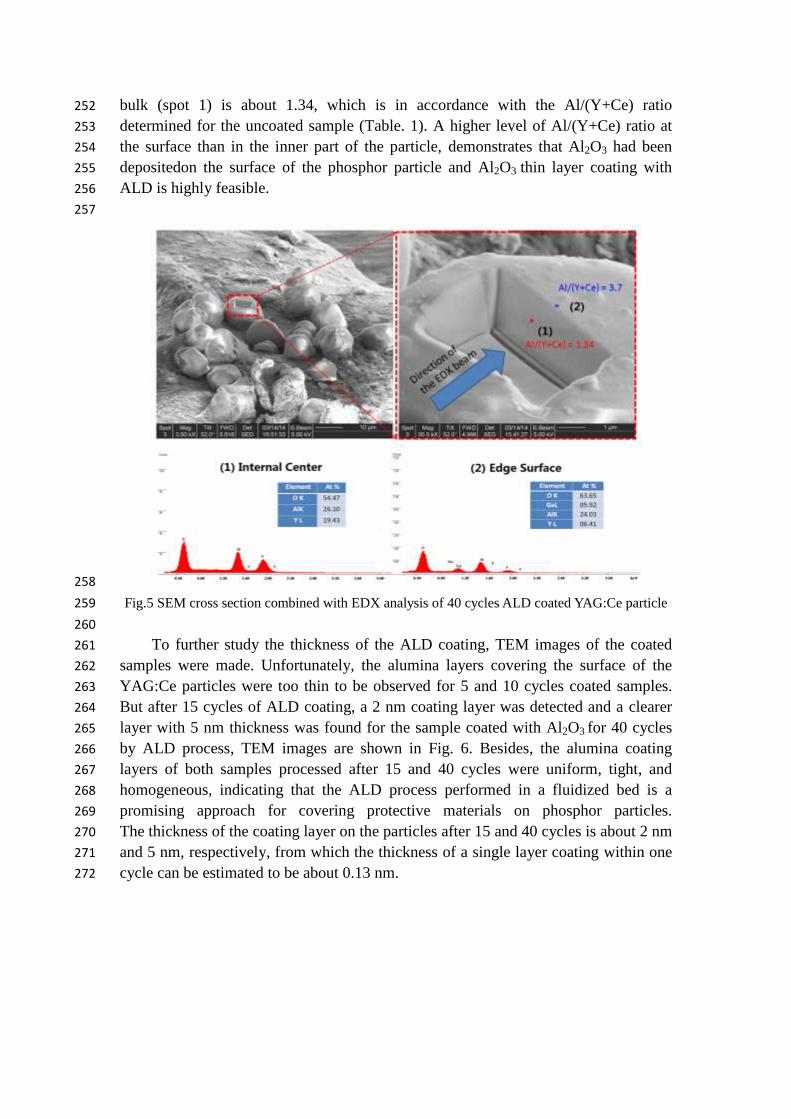
Furthermore, cross section SEM by dual beam was performed on the 40 cycles 248
coated sample, as shown in Fig. 5. The signal of Gacomes from the ions beam, which 249
was utilized to section the YAG:Ce particle. According to the EDX examination, the 250
ratio of Al/(Y+Ce) at the surface (spot 2) turns out to be about 3.7, while that in the 251
Page 9
bulk (spot 1) is about 1.34, which is in accordance with the Al/(Y+Ce) ratio 252
determined for the uncoated sample (Table. 1). A higher level of Al/(Y+Ce) ratio at 253
the surface than in the inner part of the particle, demonstrates that Al2O3 had been 254
depositedon the surface of the phosphor particle and Al2O3 thin layer coating with 255
ALD is highly feasible. 256
257
258
Fig.5 SEM cross section combined with EDX analysis of 40 cycles ALD coated YAG:Ce particle 259
260
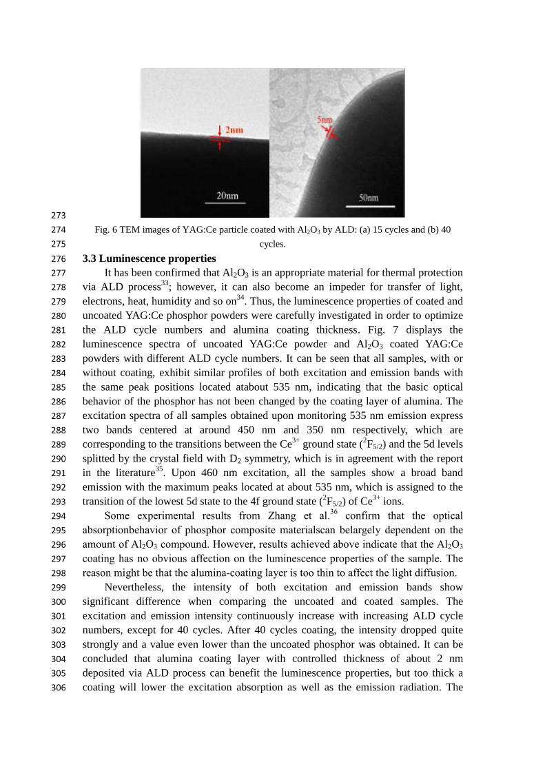
To further study the thickness of the ALD coating, TEM images of the coated 261
samples were made. Unfortunately, the alumina layers covering the surface of the 262
YAG:Ce particles were too thin to be observed for 5 and 10 cycles coated samples. 263
But after 15 cycles of ALD coating, a 2 nm coating layer was detected and a clearer 264
layer with 5 nm thickness was found for the sample coated with Al2O3 for 40 cycles 265
by ALD process, TEM images are shown in Fig. 6. Besides, the alumina coating 266
layers of both samples processed after 15 and 40 cycles were uniform, tight, and 267
homogeneous, indicating that the ALD process performed in a fluidized bed is a 268
promising approach for covering protective materials on phosphor particles. 269
The thickness of the coating layer on the particles after 15 and 40 cycles is about 2 nm 270
and 5 nm, respectively, from which the thickness of a single layer coating within one 271
cycle can be estimated to be about 0.13 nm. 272
Page 10
273
Fig. 6 TEM images of YAG:Ce particle coated with Al2O3 by ALD: (a) 15 cycles and (b) 40 274
cycles. 275
3.3 Luminescence properties 276
It has been confirmed that Al2O3 is an appropriate material for thermal protection 277
via ALD process33
; however, it can also become an impeder for transfer of light, 278
electrons, heat, humidity and so on34
. Thus, the luminescence properties of coated and 279
uncoated YAG:Ce phosphor powders were carefully investigated in order to optimize 280
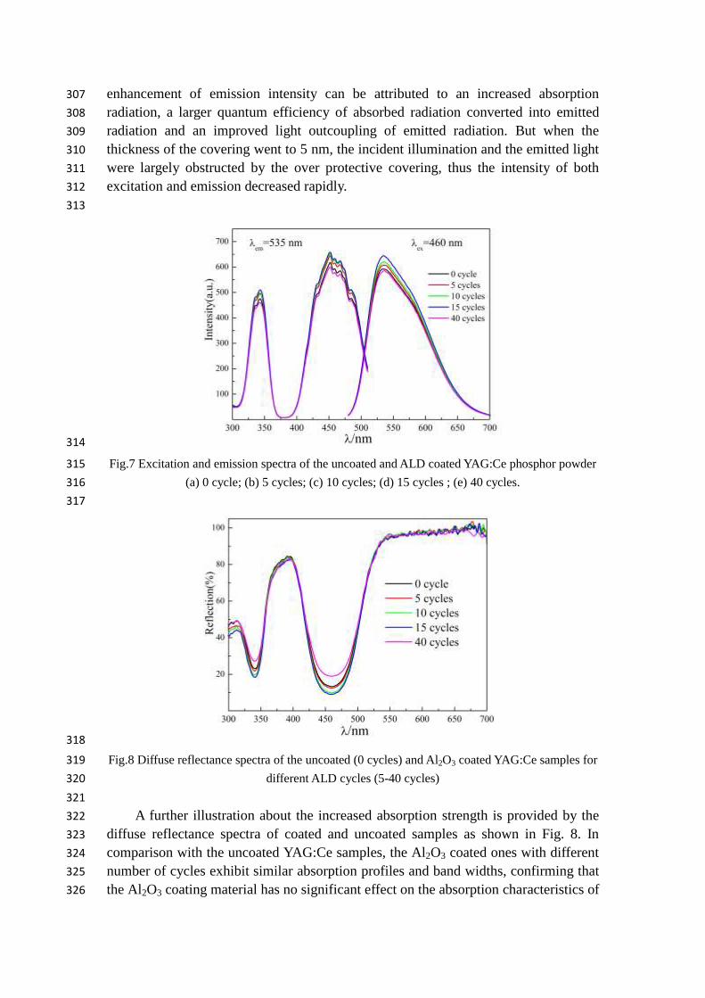
the ALD cycle numbers and alumina coating thickness. Fig. 7 displays the 281
luminescence spectra of uncoated YAG:Ce powder and Al2O3 coated YAG:Ce 282
powders with different ALD cycle numbers. It can be seen that all samples, with or 283
without coating, exhibit similar profiles of both excitation and emission bands with 284
the same peak positions located atabout 535 nm, indicating that the basic optical 285
behavior of the phosphor has not been changed by the coating layer of alumina. The 286
excitation spectra of all samples obtained upon monitoring 535 nm emission express 287
two bands centered at around 450 nm and 350 nm respectively, which are 288
corresponding to the transitions between the Ce3+
ground state (2F5/2) and the 5d levels 289
splitted by the crystal field with D2 symmetry, which is in agreement with the report 290
in the literature35
. Upon 460 nm excitation, all the samples show a broad band 291
emission with the maximum peaks located at about 535 nm, which is assigned to the 292
transition of the lowest 5d state to the 4f ground state (2F5/2) of Ce
3+ ions. 293
Some experimental results from Zhang et al.36
confirm that the optical 294
absorptionbehavior of phosphor composite materialscan belargely dependent on the 295
amount of Al2O3 compound. However, results achieved above indicate that the Al2O3 296
coating has no obvious affection on the luminescence properties of the sample. The 297
reason might be that the alumina-coating layer is too thin to affect the light diffusion. 298
Nevertheless, the intensity of both excitation and emission bands show 299
significant difference when comparing the uncoated and coated samples. The 300
excitation and emission intensity continuously increase with increasing ALD cycle 301
numbers, except for 40 cycles. After 40 cycles coating, the intensity dropped quite 302
strongly and a value even lower than the uncoated phosphor was obtained. It can be 303
concluded that alumina coating layer with controlled thickness of about 2 nm 304
deposited via ALD process can benefit the luminescence properties, but too thick a 305
coating will lower the excitation absorption as well as the emission radiation. The 306
Page 11
enhancement of emission intensity can be attributed to an increased absorption 307
radiation, a larger quantum efficiency of absorbed radiation converted into emitted 308
radiation and an improved light outcoupling of emitted radiation. But when the 309
thickness of the covering went to 5 nm, the incident illumination and the emitted light 310
were largely obstructed by the over protective covering, thus the intensity of both 311
excitation and emission decreased rapidly. 312
313
314
Fig.7 Excitation and emission spectra of the uncoated and ALD coated YAG:Ce phosphor powder 315
(a) 0 cycle; (b) 5 cycles; (c) 10 cycles; (d) 15 cycles ; (e) 40 cycles. 316
317
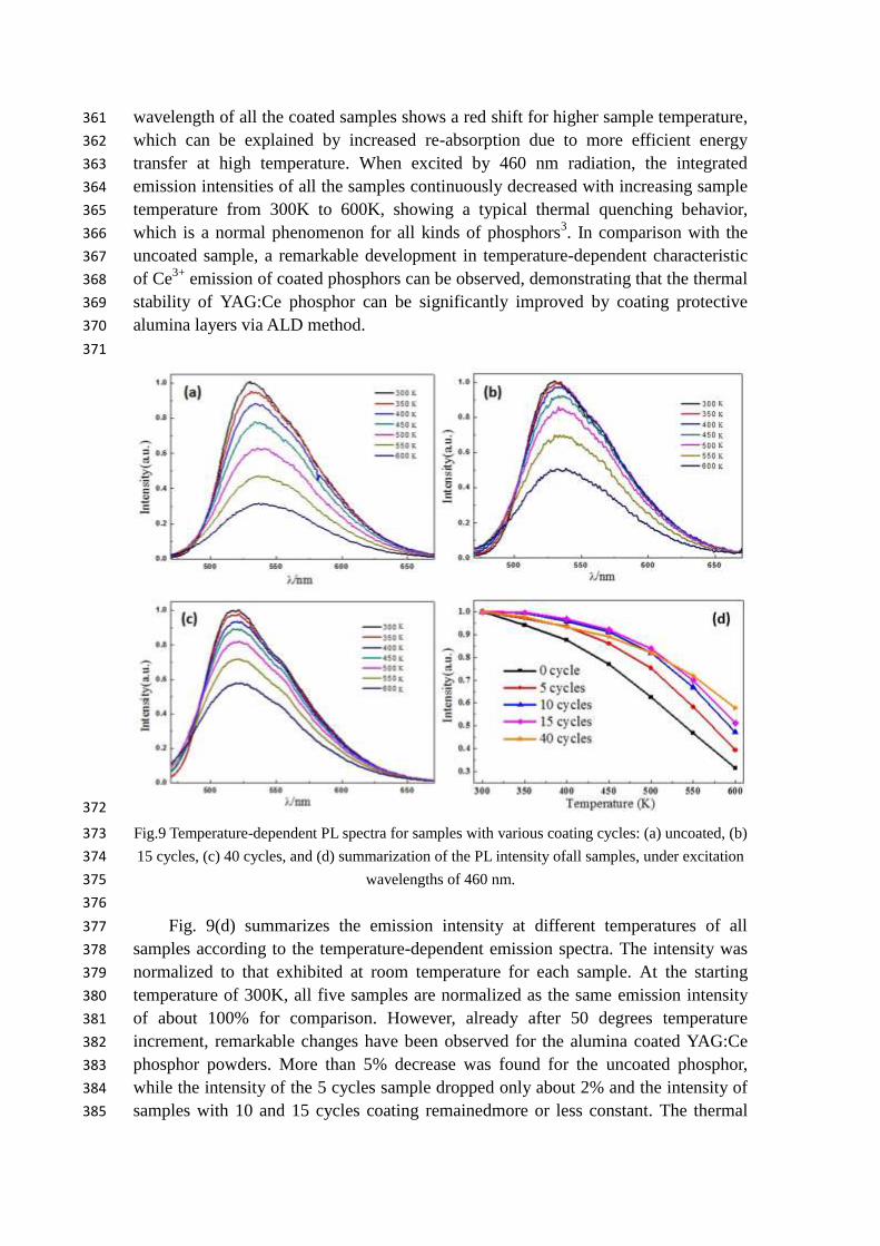
318
Fig.8 Diffuse reflectance spectra of the uncoated (0 cycles) and Al2O3 coated YAG:Ce samples for 319
different ALD cycles (5-40 cycles) 320
321
A further illustration about the increased absorption strength is provided by the 322
diffuse reflectance spectra of coated and uncoated samples as shown in Fig. 8. In 323
comparison with the uncoated YAG:Ce samples, the Al2O3 coated ones with different 324
number of cycles exhibit similar absorption profiles and band widths, confirming that 325
the Al2O3 coating material has no significant effect on the absorption characteristics of 326
Page 12
YAG:Ce phosphor powder. As compared to the uncoated phosphor, the reflection 327
(around 340 and 455 nm) decreased (i.e. adsorption around 340 and 455 nm increased) 328
for higher number of ALD cycles, except for the 40 cycles sample (Table 2). All of the 329
above results are in agreement with the conclusion made from Fig. 7, further 330
confirming that the covering thickness of the alumina coating should be optimized 331
since a high amount of Al2O3 can hamper the light absorption as well as the light 332
emission (Table 2). 333
The relative quantum efficiency is estimated by comparing the emission intensity 334
(EI) of the coated sample with that of the uncoated YAG:Ce phosphor powder from 335
the equation below: 336
337
338
Here, “QE” refers to the relative quantum efficiency; “EI” refers to the integrated 339
area under the emission spectrum, which was obtained from the emission spectra in 340
Fig. 7; “A” refers to the absorption intensity at excitation wavelength of 460 nm, 341
which was calculated from the diffuse reflection spectra (A=1 - diffuse reflectionfor 342
semi-infinite thick samples). The QE of the uncoated phosphor was taken 1.00. The 343
calculated relative QE for the uncoated and coated samples are listed in Table. 2. The 344
emission intensity of the phosphors increased with the adding of cycle numbers, and 345
so does the relative quantum efficiency, with an exception of the 40 cycles coating 346
sample. The higher relative quantum efficiency is attributed to surface passivation 347
(resulting in less non-radiative transitions at defects) and easier extraction of the 348
emitted light. In summary, the results indicate that the coated YAG:Ce samples 349
processed with10-15 cycles have better conversion abilities than the uncoated 350
material. 351
352
Table 2. The absorption of 460 nm (excitation radiation) and the relative quantum efficiency of 353
Al2O3 coated versus uncoated YAG: Ce phosphor powders. 354
Number of
coating cycles
Emission
(arb. Units)
Absorption
at 460 nm
Relative Quantum
Efficiency
0 cycle 61639 0.93 1.00
5 cycles 63070 0.94 1.01
10 cycles 64222 0.94 1.03
15 cycles 66525 0.95 1.06
40 cycles 52938 0.93 0.96
355
3.4 Thermal stability 356
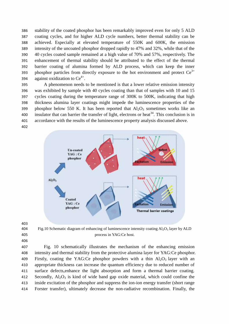
Fig. 9 displays the temperature-dependent emission spectra of the uncoated and 357
coated YAG:Ce phosphor powders prepared by ALD method, combined with the 358
summary of the dependence of the emission intensity in sample temperature (Fig. 359
9(d)). When compared with the uncoated YAG:Ce phosphor, the peak emission 360
Page 13
wavelength of all the coated samples shows a red shift for higher sample temperature, 361
which can be explained by increased re-absorption due to more efficient energy 362
transfer at high temperature. When excited by 460 nm radiation, the integrated 363
emission intensities of all the samples continuously decreased with increasing sample 364
temperature from 300K to 600K, showing a typical thermal quenching behavior, 365
which is a normal phenomenon for all kinds of phosphors3. In comparison with the 366
uncoated sample, a remarkable development in temperature-dependent characteristic 367
of Ce3+
emission of coated phosphors can be observed, demonstrating that the thermal 368
stability of YAG:Ce phosphor can be significantly improved by coating protective 369
alumina layers via ALD method. 370
371
372
Fig.9 Temperature-dependent PL spectra for samples with various coating cycles: (a) uncoated, (b) 373
15 cycles, (c) 40 cycles, and (d) summarization of the PL intensity ofall samples, under excitation 374
wavelengths of 460 nm. 375
376
Fig. 9(d) summarizes the emission intensity at different temperatures of all 377
samples according to the temperature-dependent emission spectra. The intensity was 378
normalized to that exhibited at room temperature for each sample. At the starting 379
temperature of 300K, all five samples are normalized as the same emission intensity 380
of about 100% for comparison. However, already after 50 degrees temperature 381
increment, remarkable changes have been observed for the alumina coated YAG:Ce 382
phosphor powders. More than 5% decrease was found for the uncoated phosphor, 383
while the intensity of the 5 cycles sample dropped only about 2% and the intensity of 384
samples with 10 and 15 cycles coating remainedmore or less constant. The thermal 385
Page 14
stability of the coated phosphor has been remarkably improved even for only 5 ALD 386
coating cycles, and for higher ALD cycle numbers, better thermal stability can be 387
achieved. Especially at elevated temperature of 550K and 600K, the emission 388
intensity of the uncoated phosphor dropped rapidly to 47% and 32%, while that of the 389
40 cycles coated sample remained at a high value of 70% and 57%, respectively. The 390
enhancement of thermal stability should be attributed to the effect of the thermal 391
barrier coating of alumina formed by ALD process, which can keep the inner 392
phosphor particles from directly exposure to the hot environment and protect Ce3+
393
against oxidization to Ce4+
. 394
A phenomenon needs to be mentioned is that a lower relative emission intensity 395
was exhibited by sample with 40 cycles coating than that of samples with 10 and 15 396
cycles coating during the temperature range of 300K to 500K, indicating that high 397
thickness alumina layer coatings might impede the luminescence properties of the 398
phosphor below 550 K. It has been reported that Al2O3 sometimes works like an 399
insulator that can barrier the transfer of light, electrons or heat34
. This conclusion is in 400
accordance with the results of the luminescence property analysis discussed above. 401
402
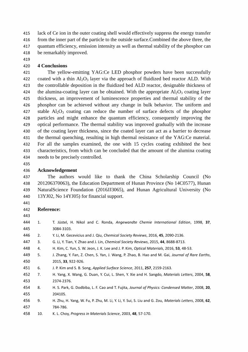
403
Fig.10 Schematic diagram of enhancing of luminescence intensity coating Al2O3 layer by ALD 404
process in YAG:Ce host. 405
406
Fig. 10 schematically illustrates the mechanism of the enhancing emission 407
intensity and thermal stability from the protective alumina layer for YAG:Ce phosphor. 408
Firstly, coating the YAG:Ce phosphor powders with a thin Al2O3 layer with an 409
appropriate thickness can increase the quantum efficiency due to reduced number of 410
surface defects,enhance the light absorption and form a thermal barrier coating. 411
Secondly, Al2O3 is kind of wide band gap oxide material, which could confine the 412
inside excitation of the phosphor and suppress the ion-ion energy transfer (short range 413
Forster transfer), ultimately decrease the non-radiative recombination. Finally, the 414
Page 15
lack of Ce ion in the outer coating shell would effectively suppress the energy transfer 415
from the inner part of the particle to the outside surface.Combined the above three, the 416
quantum efficiency, emission intensity as well as thermal stability of the phosphor can 417
be remarkably improved. 418
419
4 Conclusions 420
The yellow-emitting YAG:Ce LED phosphor powders have been successfully 421
coated with a thin Al2O3 layer via the approach of fluidized bed reactor ALD. With 422
the controllable deposition in the fluidized bed ALD reactor, designable thickness of 423
the alumina-coating layer can be obtained. With the appropriate Al2O3 coating layer 424
thickness, an improvement of luminescence properties and thermal stability of the 425
phosphor can be achieved without any change in bulk behavior. The uniform and 426
stable Al2O3 coating can reduce the number of surface defects of the phosphor 427
particles and might enhance the quantum efficiency, consequently improving the 428
optical performance. The thermal stability was improved gradually with the increase 429
of the coating layer thickness, since the coated layer can act as a barrier to decrease 430
the thermal quenching, resulting in high thermal resistance of the YAG:Ce material. 431
For all the samples examined, the one with 15 cycles coating exhibited the best 432
characteristics, from which can be concluded that the amount of the alumina coating 433
needs to be precisely controlled. 434
435
Acknowledgement 436
The authors would like to thank the China Scholarship Council (No 437
201206370063), the Education Department of Hunan Province (No 14C0577), Hunan 438
NaturalScience Foundation (2016JJ3065), and Hunan Agricultural University (No 439
13YJ02, No 14YJ05) for financial support. 440
441
Reference: 442
443
1. T. Jüstel, H. Nikol and C. Ronda, Angewandte Chemie International Edition, 1998, 37, 444
3084-3103. 445
2. Y. Li, M. Gecevicius and J. Qiu, Chemical Society Reviews, 2016, 45, 2090-2136. 446
3. G. Li, Y. Tian, Y. Zhao and J. Lin, Chemical Society Reviews, 2015, 44, 8688-8713. 447
4. H. Kim, C. Yun, S. W. Jeon, J. K. Lee and J. P. Kim, Optical Materials, 2016, 53, 48-53. 448
5. J. Zhang, Y. Fan, Z. Chen, S. Yan, J. Wang, P. Zhao, B. Hao and M. Gai, Journal of Rare Earths, 449
2015, 33, 922-926. 450
6. J. P. Kim and S. B. Song, Applied Surface Science, 2011, 257, 2159-2163. 451
7. H. Yang, X. Wang, G. Duan, Y. Cui, L. Shen, Y. Xie and H. Sangdo, Materials Letters, 2004, 58, 452
2374-2376. 453
8. H. S. Park, G. Dodbiba, L. F. Cao and T. Fujita, Journal of Physics: Condensed Matter, 2008, 20, 454
204105. 455
9. H. Zhu, H. Yang, W. Fu, P. Zhu, M. Li, Y. Li, Y. Sui, S. Liu and G. Zou, Materials Letters, 2008, 62, 456
784-786. 457
10. K. L. Choy, Progress in Materials Science, 2003, 48, 57-170. 458
Page 16
11. J. Chao, L. Fei, L. Hua, H. Shao-liu, L. Bo and W. You-qing, Applied Surface Science, 2005, 246, 459
207-213. 460
12. O. J. Kilbury, K. S. Barrett, X. Fu, J. Yin, D. S. Dinair, C. J. Gump, A. W. Weimer and D. M. King, 461
Powder Technology, 2012, 221, 26-35. 462
13. N. Avci, J. Musschoot, P. F. Smet, K. Korthout, A. Avci, C. Detavernier and D. Poelman, Journal 463
of The Electrochemical Society, 2009, 156, J333-J337. 464
14. R. Beetstra, U. Lafont, J. Nijenhuis, E. M. Kelder and J. R. van Ommen, Chemical Vapor 465
Deposition, 2009, 15, 227-233. 466
15. M. Ritala, K. Kukli, A. Rahtu, P. I. Räisänen, M. Leskelä, T. Sajavaara and J. Keinonen, Science, 467
2000, 288, 319-321. 468
16. Z. Wang, H. Guo, F. Shen, G. Yang, Y. Zhang, Y. Zeng, L. Wang, H. Xiao and S. Deng, 469
Chemosphere, 2015, 119, 646-653. 470
17. J. Lee, D. H. K. Jackson, T. Li, R. E. Winans, J. A. Dumesic, T. F. Kuech and G. W. Huber, Energy & 471
Environmental Science, 2014, 7, 1657-1660. 472
18. M. Zeng, X. Peng, J. Liao, G. Wang, Y. Li, J. Li, Y. Qin, J. Wilson, a. song and S. Lin, Physical 473
Chemistry Chemical Physics, 2016, DOI: 10.1039/C6CP01299J. 474
19. L. H. Kim, Y. J. Jeong, T. K. An, S. Park, J. H. Jang, S. Nam, J. Jang, S. H. Kim and C. E. Park, 475
Physical Chemistry Chemical Physics, 2016, 18, 1042-1049. 476
20. X. Dong, X. Fang, M. Lv, B. Lin, S. Zhang, J. Ding and N. Yuan, Journal of Materials Chemistry A, 477
2015, 3, 5360-5367. 478
21. J. D. Ferguson, A. W. Weimer and S. M. George, Chemistry of Materials, 2000, 12, 3472-3480. 479
22. J. Lu, Y. H. Wang, J. B. Zang and Y. N. Li, Applied Surface Science, 2007, 253, 3485-3488. 480
23. K. Nevalainen, R. Suihkonen, P. Eteläaho, J. Vuorinen, P. Järvelä, N. Isomäki, C. Hintze and M. 481
Leskelä, Journal of Vacuum Science & Technology A, 2009, 27, 929-936. 482
24. P. A. Williams, C. P. Ireland, P. J. King, P. A. Chater, P. Boldrin, R. G. Palgrave, J. B. Claridge, J. R. 483
Darwent, P. R. Chalker and M. J. Rosseinsky, Journal of Materials Chemistry, 2012, 22, 484
20203-20209. 485
25. D. M. King, J. Li, X. Liang, S. I. Johnson, M. M. Channel and A. W. Weimer, Crystal Growth & 486
Design, 2009, 9, 2828-2834. 487
26. D. M. King, X. Liang, P. Li and A. W. Weimer, Thin Solid Films, 2008, 516, 8517-8523. 488
27. J. Zhao and Y. Wang, Nano Energy, 2013, 2, 882-889. 489
28. L. Xiong, Y. Xu, T. Tao, X. Du and J. Li, Journal of Materials Chemistry, 2011, 21, 4937-4944. 490
29. D. Valdesueiro, M. K. Prabhu, C. Guerra-Nunez, C. S. S. Sandeep, S. Kinge, L. D. A. Siebbeles, L. 491
C. P. M. de Smet, G. M. H. Meesters, M. T. Kreutzer, A. J. Houtepen and J. R. van Ommen, The 492
Journal of Physical Chemistry C, 2016, 120, 4266-4275. 493
30. H. J. Kim, M. W. Kim, H. s. Kim, H. S. Kim, S. H. Kim, S. W. Lee, B. H. Choi, B. K. Jeong and H. h. 494
Lee, Molecular Crystals and Liquid Crystals, 2006, 459, 239/[519]-245/[525]. 495
31. H. K. Yang, H. M. Noh and J. H. Jeong, Solid State Sciences, 2014, 27, 43-46. 496
32. M. Kučera, K. Nitsch, M. Nikl and M. Hanuš, Radiation Measurements, 2010, 45, 449-452. 497
33. V. Edlmayr, M. Moser, C. Walter and C. Mitterer, Surface and Coatings Technology, 2010, 204, 498
1576-1581. 499
34. A. Kafizas and I. P. Parkin, Chemical Society Reviews, 2012, 41, 738-781. 500
35. Z. Zhi, L. Suqin, W. Fengchao and L. Younian, Journal of Physics D: Applied Physics, 2012, 45, 501
195105. 502
Page 17
36. C. Zhang and J. Lin, Chemical Society Reviews, 2012, 41, 7938-7961. 503