102
Alu minium Casting Allo ys
7/31/2019 Aluminium Casting Alloys EnglishVersion 2011
http://slidepdf.com/reader/full/aluminium-casting-alloys-englishversion-2011 1/102
Aluminium Casting Alloys

7/31/2019 Aluminium Casting Alloys EnglishVersion 2011
http://slidepdf.com/reader/full/aluminium-casting-alloys-englishversion-2011 2/102
Aluminium Casting Alloys
7/31/2019 Aluminium Casting Alloys EnglishVersion 2011
http://slidepdf.com/reader/full/aluminium-casting-alloys-englishversion-2011 3/102
Aluminium Casting Alloys
Aluminium Casting Alloys
7/31/2019 Aluminium Casting Alloys EnglishVersion 2011
http://slidepdf.com/reader/full/aluminium-casting-alloys-englishversion-2011 4/102
Aluminium Casting Alloys
Content
Introduction 5
Recycled aluminium 6
Technology and service
for our customers
• Quality Management 7
• Work safety and health 8
protection• Environmental protection
Aluminium and aluminium 9
casting alloys
• Aluminium – Material properties
• Recycling of aluminium
• Shaping by casting 10
Product range and 11
form of delivery
• Technical consultancy 12
service
Selecting aluminium 13
casting alloys
• Criteria for the selection of 14
aluminium casting alloys
• Inuence of the 18
most important alloying
elements on aluminium
casting alloys
Inuencing the 19
microstructural formation of
aluminium castings
• Grain renement 20
• Modication of AlSi eutectic 21
• Renement of 23
primary silicon
Melt quality and melt cleaning 24
• Avoiding impurities 25
• Melt testing and 28
inspection procedure
• Thermal analysis 30
Selecting the casting process 31
• Pressure die casting 32process
• Gravity die casting process
• Sand casting process 34
Casting-compliant design 35
Solidication simulation 37
and thermography
Avoiding casting defects 38
Heat treatment of 40
aluminium castings
• Metallurgy –
fundamental principles
• Solution annealing 41
• Quenching
• Ageing 42
Mechanical machining of 44
aluminium castings
Welding and joining 45
aluminium castings
• Suitability and behaviour
• Applications in the
aluminium sector
• Welding processes
• Weld preparation 47
• Weld ller materials
Surface treatment: corrosion 48
and corrosion protection
Information on physical data, 50
strength properties and
strength calculations
Notes on the casting 51alloy tables
Overview: Aluminium casting 52
alloys by alloy group
Eutectic aluminium-silicon 59
casting alloys
Near-eutectic wheel 63
casting alloys
The 10 per cent aluminium- 66
silicon casting alloys
The 7 and 5 per cent 71
aluminium-silicon
casting alloys
Al SiCu casting alloys 76
AlMg casting alloys 81
Casting alloys for special 87
applications
4
7/31/2019 Aluminium Casting Alloys EnglishVersion 2011
http://slidepdf.com/reader/full/aluminium-casting-alloys-englishversion-2011 5/102
Aluminium Casting Alloys
In the second part, all technical aspects
which have to be taken into account in
the selection of an aluminium casting al-
loy are explained in detail. All details are
based on the DIN EN 1676: 2010 standard.
The third part begins with notes on the
physical data, tensile strength charac-teristics and strength calculations of
aluminium casting alloys. Subsequently,
all standardised aluminium casting alloys
in accordance with DIN EN 1676 as well
as common, non-standardised casting
alloys are depicted in a summary table
together with their casting/technical and
other typical similarities in “alloy families”.
The aim of this new, revised and rede-
signed Aluminium Casting Alloys Cata-
logue is to give the user of aluminium
Many of you have most certainly worked
with the “old“ Aluminium Casting Alloys
Catalogue – over the years in thousands
of workplaces in the aluminium indus-
try, it has become a standard reference
book, a reliable source of advice about
all matters relating to the selection and
processing of aluminium casting alloys.
Even if you are holding this Aluminium
Casting Alloys Catalogue in your hands
for the rst time, you will quickly nd your
way around with the help of the following
notes and the catalogue‘s detailed index.
How is this Aluminium Casting Alloys
Catalogue structured? The catalogue
consists of three separate parts. In the
rst part, we provide details on our com-
pany – a proven supplier of aluminium
casting alloys.
Introduction
casting alloys a clear, well laid-out com-
panion for practical application. Should
you have any questions concerning the
selection and use of aluminium casting
alloys, please contact our foundry con-
sultants or our sales staff.
You can also refer to www.aleris.com.
We would be pleased to advise
you and wish you every success
in your dealings with aluminium
casting alloys!
5
7/31/2019 Aluminium Casting Alloys EnglishVersion 2011
http://slidepdf.com/reader/full/aluminium-casting-alloys-englishversion-2011 6/102
7/31/2019 Aluminium Casting Alloys EnglishVersion 2011
http://slidepdf.com/reader/full/aluminium-casting-alloys-englishversion-2011 7/102
7/31/2019 Aluminium Casting Alloys EnglishVersion 2011
http://slidepdf.com/reader/full/aluminium-casting-alloys-englishversion-2011 8/102
Aluminium Casting Alloys
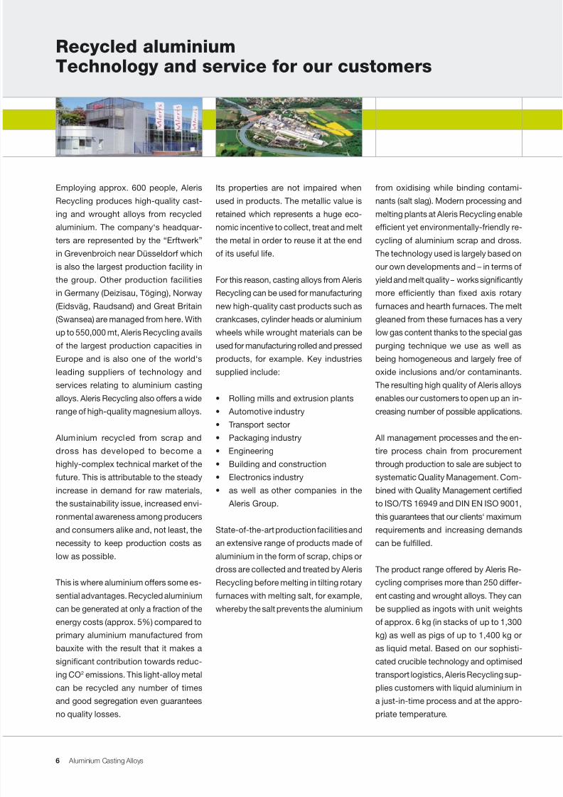
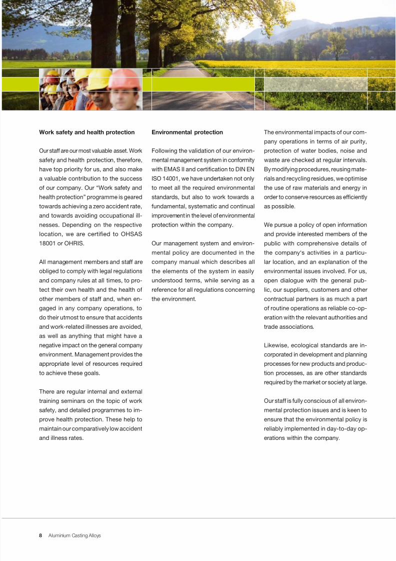
Work safety and health protection
Our staff are our most valuable asset. Work
safety and health protection, therefore,
have top priority for us, and also make
a valuable contribution to the success
of our company. Our “Work safety and
health protection” programme is gearedtowards achieving a zero accident rate,
and towards avoiding occupational ill-
nesses. Depending on the respective
location, we are certied to OHSAS
18001 or OHRIS.
All management members and staff are
obliged to comply with legal regulations
and company rules at all times, to pro-
tect their own health and the health of
other members of staff and, when en-
gaged in any company operations, to
do their utmost to ensure that accidents
and work-related illnesses are avoided,
as well as anything that might have a
negative impact on the general company
environment. Management provides the
appropriate level of resources required
to achieve these goals.
There are regular internal and externaltraining seminars on the topic of work
safety, and detailed programmes to im-
prove health protection. These help to
maintain our comparatively low accident
and illness rates.
Environmental protection
Following the validation of our environ-
mental management system in conformity
with EMAS II and certication to DIN EN
ISO 14001, we have undertaken not only
to meet all the required environmental
standards, but also to work towards afundamental, systematic and continual
improvement in the level of environmental
protection within the company.
Our management system and environ-
mental policy are documented in the
company manual which describes all
the elements of the system in easily
understood terms, while serving as a
reference for all regulations concerning
the environment.
The environmental impacts of our com-
pany operations in terms of air purity,
protection of water bodies, noise and
waste are checked at regular intervals.
By modifying procedures, reusing mate-
rials and recycling residues, we optimise
the use of raw materials and energy in
order to conserve resources as efcientlyas possible.
We pursue a policy of open information
and provide interested members of the
public with comprehensive details of
the company‘s activities in a particu-
lar location, and an explanation of the
environmental issues involved. For us,
open dialogue with the general pub-
lic, our suppliers, customers and other
contractual partners is as much a part
of routine operations as reliable co-op-
eration with the relevant authorities and
trade associations.
Likewise, ecological standards are in-
corporated in development and planning
processes for new products and produc-
tion processes, as are other standards
required by the market or society at large.
Our staff is fully conscious of all environ-
mental protection issues and is keen to
ensure that the environmental policy is
reliably implemented in day-to-day op-
erations within the company.
8
7/31/2019 Aluminium Casting Alloys EnglishVersion 2011
http://slidepdf.com/reader/full/aluminium-casting-alloys-englishversion-2011 9/102
Aluminium Casting Alloys
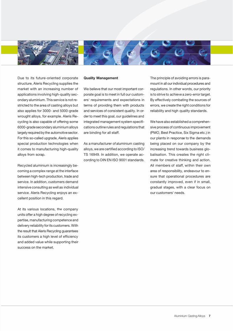
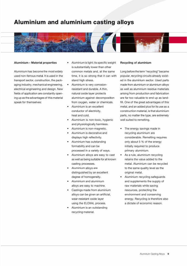
Aluminium and aluminium casting alloys
Recycling of aluminium
Long before the term “recycling” became
popular, recycling circuits already exist-
ed in the aluminium sector. Used parts
made from aluminium or aluminium alloys
as well as aluminium residue materials
arising from production and fabricationare far too valuable to end up as land-
ll. One of the great advantages of this
metal, and an added plus for its use as a
construction material, is that aluminium
parts, no matter the type, are extremely
well suited to remelting.
• The energy savings made in
recycling aluminium are
considerable. Remelting requires
only about 5 % of the energy
initially required to produce
primary aluminium.
• As a rule, aluminium recycling
retains the value added to the
metal. Aluminium can be recycled
to the same quality level as the
original metal.
• Aluminium recycling safeguards
and supplements the supply of
raw materials while savingresources, protecting the
environment and conserving
energy. Recycling is therefore also
a dictate of economic reason.
• Aluminium is light; its specic weight
is substantially lower than other
common metals and, at the same
time, it is so strong that it can with
stand high stress.
• Aluminium is very corrosion-
resistant and durable. A thin,
natural oxide layer protectsaluminium against decomposition
from oxygen, water or chemicals.
• Aluminium is an excellent
conductor of electricity,
heat and cold.
• Aluminium is non-toxic, hygienic
and physiologically harmless.
• Aluminium is non-magnetic.
• Aluminium is decorative and
displays high reectivity.
• Aluminium has outstanding
formability and can be
processed in a variety of ways.
• Aluminium alloys are easy to cast
as well as being suitable for all known
casting processes.
• Aluminium alloys are
distinguished by an excellent
degree of homogeneity.
• Aluminium and aluminium
alloys are easy to machine.• Castings made from aluminium
alloys can be given an articial,
wear-resistant oxide layer
using the ELOXAL process.
• Aluminium is an outstanding
recycling material.
Aluminium – Material properties
Aluminium has become the most widely
used non-ferrous metal. It is used in the
transport sector, construction, the pack-
aging industry, mechanical engineering,
electrical engineering and design. New
elds of application are constantly open-ing up as the advantages of this material
speak for themselves:
9
7/31/2019 Aluminium Casting Alloys EnglishVersion 2011
http://slidepdf.com/reader/full/aluminium-casting-alloys-englishversion-2011 10/102
Aluminium Casting Alloys
Shaping by casting
Casting represents the shortest route
from raw materials to nished parts – a
fact which has been known for ve thou-
sand years. Through continuous further
development and, in part, by a selective
return to classic methods such as thelost-form process, casting has remained
at the forefront of technical progress.
The most important advantage of the
casting process is that the possibilities
of shaping the part are practically limit-
less. Castings are, therefore, easier and
cheaper to produce than machined and/
or joined components. The general waiv-
ing of subsequent machining not only
results in a good density and path of
force lines but also in high form strength.
Furthermore, waste is also avoided. As a
rule, the casting surface displays a tight,
ne-grained structure and, consequently,
is also resistant to wear and corrosion.
The experience accumulated over ma-
ny decades, the use of state-of-the-art
technology in scrap preparation, remelt-
ing and exhaust gas cleaning as well
as our constant efforts to develop new,
environmentally-sound manufactur-
ing technology puts us in a position to
achieve the best possible and efcientrecycling rates. At the same time, they
also help us to make the most efcient
use of energy and auxiliary materials.
The variety of modern casting process-
es makes it possible to face up to the
economic realities, i.e. the optimisation
of investment expenditure and costs
in relation to the number of units. With
casting, the variable weighting of pro-
duction costs and quality requirements
are also possible.
When designing the shape of the cast-
ing, further possibilities arise from the
use of inserts and/or from joining the
part to other castings or workpieces.
In the last decade, aluminium has at-
tained a leading position among cast
metals because, in addition to its other
positive material properties, this light
metal offers the greatest possible variety
of casting and joining processes.
10
7/31/2019 Aluminium Casting Alloys EnglishVersion 2011
http://slidepdf.com/reader/full/aluminium-casting-alloys-englishversion-2011 11/102
Aluminium Casting Alloys
Product range and form of delivery
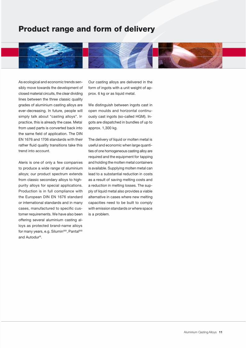
Our casting alloys are delivered in the
form of ingots with a unit weight of ap-
prox. 6 kg or as liquid metal.
We distinguish between ingots cast in
open moulds and horizontal continu-
ously cast ingots (so-called HGM). In-
gots are dispatched in bundles of up toapprox. 1,300 kg.
The delivery of liquid or molten metal is
useful and economic when large quanti-
ties of one homogeneous casting alloy are
required and the equipment for tapping
and holding the molten metal containers
is available. Supplying molten metal can
lead to a substantial reduction in costs
as a result of saving melting costs and
a reduction in melting losses. The sup-
ply of liquid metal also provides a viable
alternative in cases where new melting
capacities need to be built to comply
with emission standards or where space
is a problem.
As ecological and economic trends sen-
sibly move towards the development of
closed material circuits, the clear dividing
lines between the three classic quality
grades of aluminium casting alloys are
ever-decreasing. In future, people will
simply talk about “casting alloys”. In
practice, this is already the case. Metalfrom used parts is converted back into
the same eld of application. The DIN
EN 1676 and 1706 standards with their
rather uid quality transitions take this
trend into account.
Aleris is one of only a few companies
to produce a wide range of aluminium
alloys; our product spectrum extends
from classic secondary alloys to high-
purity alloys for special applications.
Production is in full compliance with
the European DIN EN 1676 standard
or international standards and in many
cases, manufactured to specic cus-
tomer requirements. We have also been
offering several aluminium casting al-
loys as protected brand-name alloys
for many years, e.g. Silumin ®® , Pantal ®®
and Autodur ®.
11
7/31/2019 Aluminium Casting Alloys EnglishVersion 2011
http://slidepdf.com/reader/full/aluminium-casting-alloys-englishversion-2011 12/102
Aluminium Casting Alloys
Technical consultancy service
The technical consultancy service is
the address for questions relating to
foundry technology. We provide assis-
tance in clarifying aluminium casting alloy
designations as stated in German and
international standards or the temperconditions for castings. We also offer
advice on the selection of alloys and can
provide aluminium foundries or users of
castings with information on:
• Aluminium casting alloys
• Chemical and physical properties
• Casting and solidication
behaviour
• Casting processes and details
regarding foundry technology
• Melt treatment possibilities, such as
cleaning, degassing, modication
or grain renement
• Possibilities of inuencing the
strength of castings by means
of alloying elements or heat
treatment
• Questions relating to surface
nish and surface protection.
Technical consultants also provide as-
sistance in evaluating casting defects or
surface aws and offer suggestions with
regard to eliminating defects. They sup-
ply advice on the design of castings, the
construction of dies, the casting system
and the conguration of feeders.
Technical consultants also provide tech-
nical support to aluminium foundries in
the preparation of chemical analyses,
microsections and structural analyses.
Customer feedback coupled with exten-
sive experience in the foundry sector fa-
cilitates the continuous optimisation and
quality improvement of our aluminium
casting alloys.
In co-operation with our customers, we
are working on gaining wider acceptance
of our aluminium casting alloys in new
elds of application.
Where required and especially where
fundamental problems arise, we arrange
contracts with leading research institutes
in Europe and North America.
12
7/31/2019 Aluminium Casting Alloys EnglishVersion 2011
http://slidepdf.com/reader/full/aluminium-casting-alloys-englishversion-2011 13/102
Aluminium Casting Alloys
As far as possible, the use of common
aluminium casting alloys is recommended.
These involve well-known and proven
casting alloys and we stand fully behind
the quality properties of these casting
alloys which are often manufactured in
large quantities, are more cost-effective
than special alloys and, in most cases,can be delivered at short notice.
In the European DIN EN 1676 and DIN
EN 1706 standards, the most important
aluminium casting alloys have been col-
lated in a version which is valid Europe-
wide. Consequently, there are already
more than 41 standard aluminium casting
alloys available.
Aluminium foundries should – according
to their respective structure – limit them-
selves to as small a number of casting
alloys as possible in order to use their
melting equipment economically, to keep
inventories as low as possible and to re-
duce the risk of mixing alloys.
With regard to the quality of a casting,
it is more sensible to process a casting
alloy which is operational in use than one
which displays slightly better properties
on paper but is actually more difcult to
process. The quality potential of a cast-
ing alloy is only exploited in a casting if
the cast piece is as free as possible of
casting defects and is suitable for subse-
quent process steps (e.g. heat treatment).
Our sales team and technicians are on
hand to provide foundries and usersof castings with assistance in select-
ing the correct aluminium casting alloy.
To supplement and provide greater depth
to our technical explanations, we refer
you to standard works on aluminium
and aluminium casting alloys. Further
details on other specialist literature are
available and can be requested at any
time. We would be delighted to advise
you in such matters.
Should you have any queries or com-
ments, which are always welcome,
please contact our technical service.
Standard works on aluminium and alu-
minium casting alloys:
• “Aluminium-Taschenbuch”, Verlag
Beuth, Düsseldorf
• “Aluminium viewed from within -
Prole of a modern metal”, Prof.
Dr. D. G. Altenpohl, Verlag Beuth,
Düsseldorf.
Once the requirements of a casting
have been determined, the selection of
the correct casting alloy from the mul-
titude of possibilities often represents
a problem for the designer and also for
the foundryman. In this case, the “Alu-
minium-Taschenbuch” can be of great
assistance.
Selecting aluminium casting alloys
13
7/31/2019 Aluminium Casting Alloys EnglishVersion 2011
http://slidepdf.com/reader/full/aluminium-casting-alloys-englishversion-2011 14/102
Aluminium Casting Alloys
different casting alloys are compared.
These casting alloys are used for high-
grade construction components, espe-
cially for critical parts.
“hard”
The casting alloys of this group must
display a certain tensile strength and
hardness without particular requirements
being placed on the metal‘s elongation.
First of all, Al SiCu alloys belong to this
group. Due to their Cu, Mg and Zn con-
tent, these casting alloys experience acertain amount of self-hardening after
casting (approx. 1 week). These alloys
are particularly important for pressure
die casting since it is in pressure die
casting – except for special processes
such as vacuum die casting – that pro-
cess-induced structural defects occur,
preventing high elongation values. Due
to its particularly strong self-hardening
characteristics, the Autodur casting al-
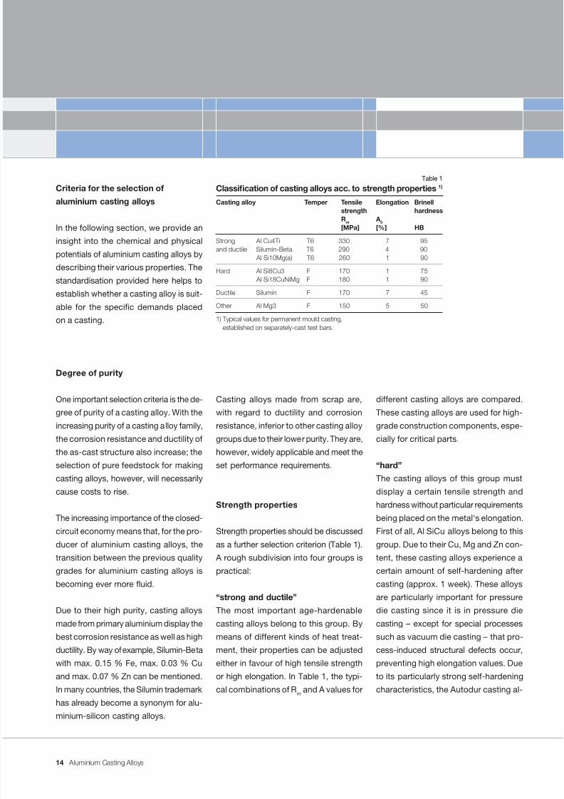
Criteria for the selection of
aluminium casting alloys
In the following section, we provide an
insight into the chemical and physical
potentials of aluminium casting alloys by
describing their various properties. The
standardisation provided here helps toestablish whether a casting alloy is suit-
able for the specic demands placed
on a casting.
Degree of purity
One important selection criteria is the de-
gree of purity of a casting alloy. With the
increasing purity of a casting alloy family,
the corrosion resistance and ductility of
the as-cast structure also increase; the
selection of pure feedstock for making
casting alloys, however, will necessarily
cause costs to rise.
The increasing importance of the closed-
circuit economy means that, for the pro-
ducer of aluminium casting alloys, the
transition between the previous qualitygrades for aluminium casting alloys is
becoming ever more uid.
Due to their high purity, casting alloys
made from primary aluminium display the
best corrosion resistance as well as high
ductility. By way of example, Silumin-Beta
with max. 0.15 % Fe, max. 0.03 % Cu
and max. 0.07 % Zn can be mentioned.
In many countries, the Silumin trademark
has already become a synonym for alu-minium-silicon casting alloys.
Casting alloys made from scrap are,
with regard to ductility and corrosion
resistance, inferior to other casting alloy
groups due to their lower purity. They are,
however, widely applicable and meet the
set performance requirements.
Strength properties
Strength properties should be discussed
as a further selection criterion (Table 1).
A rough subdivision into four groups ispractical:
“strong and ductile”
The most important age-hardenable
casting alloys belong to this group. By
means of different kinds of heat treat-
ment, their properties can be adjusted
either in favour of high tensile strength
or high elongation. In Table 1, the typi-
cal combinations of R m and A values for
Classication of casting alloys acc. to strength properties 1)
Casting alloy Temper Tensile Elongation Brinellstrength hardnessRm A5
[MPa] [%] HB
Strong Al Cu4Ti T6 330 7 95and ductile Silumin-Beta T6 290 4 90
Al Si10Mg(a) T6 260 1 90
Hard Al Si8Cu3 F 170 1 75
Al Si18CuNiMg F 180 1 90
Ductile Silumin F 170 7 45
Other Al Mg3 F 150 5 50
1) Typical values for permanent mould casting,established on separately-cast test bars.
Table 1
14
7/31/2019 Aluminium Casting Alloys EnglishVersion 2011
http://slidepdf.com/reader/full/aluminium-casting-alloys-englishversion-2011 15/102
Aluminium Casting Alloys
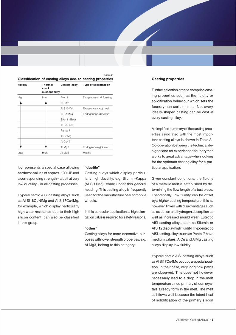
Casting properties
Further selection criteria comprise cast-
ing properties such as the uidity or
solidication behaviour which sets the
foundryman certain limits. Not every
ideally-shaped casting can be cast in
every casting alloy.
A simplied summary of the casting prop-
erties associated with the most impor-
tant casting alloys is shown in Table 2.
Co-operation between the technical de-
signer and an experienced foundryman
works to great advantage when looking
for the optimum casting alloy for a par-
ticular application.
Given constant conditions, the uidity
of a metallic melt is established by de-
termining the ow length of a test piece.
Theoretically, low uidity can be offset
by a higher casting temperature; this is,
however, linked with disadvantages such
as oxidation and hydrogen absorption as
well as increased mould wear. Eutectic
AlSi casting alloys such as Silumin or
Al Si12 display high uidity. Hypoeutectic
AlSi casting alloys such as Pantal 7 havemedium values. AlCu and AlMg casting
alloys display low uidity.
Hypereutectic AlSi casting alloys such
as Al Si17Cu4Mg occupy a special posi-
tion. In their case, very long ow paths
are observed. This does not however
necessarily lead to a drop in the melt
temperature since primary silicon crys-
tals already form in the melt. The melt
still ows well because the latent heatof solidication of the primary silicon
“ductile”
Casting alloys which display particu-
larly high ductility, e.g. Silumin-Kappa
(Al Si11Mg), come under this general
heading. This casting alloy is frequently
used for the manufacture of automobile
wheels.
In this particular application, a high elon-
gation value is required for safety reasons.
“other”
Casting alloys for more decorative pur-poses with lower strength properties, e.g.
Al Mg3, belong to this category.
loy represents a special case allowing
hardness values of approx. 100 HB and
a corresponding strength – albeit at very
low ductility – in all casting processes.
Hypereutectic AlSi casting alloys such
as Al Si18CuNiMg and Al Si17Cu4Mg,
for example, which display particularly
high wear resistance due to their high
silicon content, can also be classied
in this group.
Classication of casting alloys acc. to casting properties
Fluidity Thermal Casting alloy Type of solidicationcracksusceptibility
High Low Silumin Exogenous-shell forming
Al Si12
Al S12(Cu) Exogenous-rough wall
Al Si10Mg Endogenous-dendritic
Silumin-Beta
Al Si8Cu3
Pantal 7
Al Si5Mg
Al Cu4Ti
Al Mg3 Endogenous-globular
Low High Al Mg5 Mushy
Table 2
15
7/31/2019 Aluminium Casting Alloys EnglishVersion 2011
http://slidepdf.com/reader/full/aluminium-casting-alloys-englishversion-2011 16/102
Aluminium Casting Alloys
heats up the remainder of the melt. The
already solidied silicon, however, causes
increased mould wear and very uneven
distribution in the castings. In thesecasting alloys, high melting and holding
temperatures are necessary so that a
casting temperature of at least 720 °C
for pressure die casting and 740 °C
for sand and gravity die casting has to
be attained.
The susceptibility to hot tearing is almost
the opposite of uidity (Tables 2 and 3).
By hot tearing, we mean a separation of
the already crystallised phases during
solidication, e.g. under the inuence of
shrinkage or other tensions which can
be transmitted via the casting moulds.
The cracks or tears arising can be healed
by, among other things, the feeding of
residual melt. Eutectic and near-eutectic
AlSi casting alloys also behave particularly
well in this case, while AlCu and AlMg
casting alloys behave particularly badly.
In practice, there are mixed forms and
transitional forms of these solidication
modes. The solidication behaviour is
responsible for the formation of shrink-
age cavities and porosity, for example,
or other defects in the cast structure
as it determines the distribution of the
volume decit in the casting. To curbthe aforementioned casting defects,
casting/technical measures need to be
taken: e.g. by making adjustments to
the sprue system, the thermal balance
of the mould or by controlling the gas
content of the melt. A volume decit
occurs during transition from liquid to
solid state. This is quite small in high
silicon casting alloys since the silicon
increases in volume during solidication.
In any case, the volume decit incurred
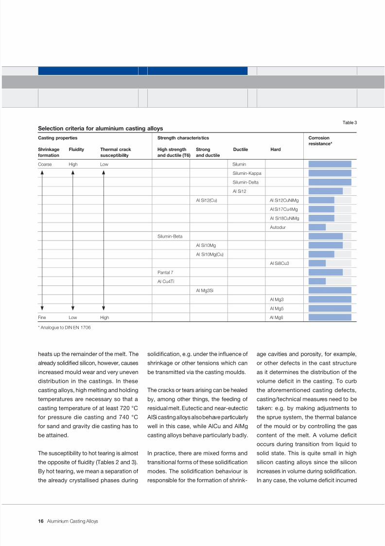
Selection criteria for aluminium casting alloys
Casting properties Strength characteristics Corrosionresistance*
Shrinkage Fluidity Thermal crack High strength Strong Ductile Hardformation susceptibility and ductile (T6) and ductile
Coarse High Low Silumin
Silumin-Kappa
Silumin-Delta
Al Si12
Al Si12(Cu) Al Si12CuNiMg
Al Si17Cu4Mg
Al Si18CuNiMg
Autodur
Silumin-Beta
Al Si10Mg
Al Si10Mg(Cu)
Al Si8Cu3
Pantal 7
Al Cu4Ti
Al Mg3Si
Al Mg3
Al Mg5
Fine Low High Al Mg9
* Analogue to DIN EN 1706
Table 3
16
7/31/2019 Aluminium Casting Alloys EnglishVersion 2011
http://slidepdf.com/reader/full/aluminium-casting-alloys-englishversion-2011 17/102
Aluminium Casting Alloys
needs to be offset as far as possible by
casting/technical means (see also the
section on “Avoiding casting defects”).
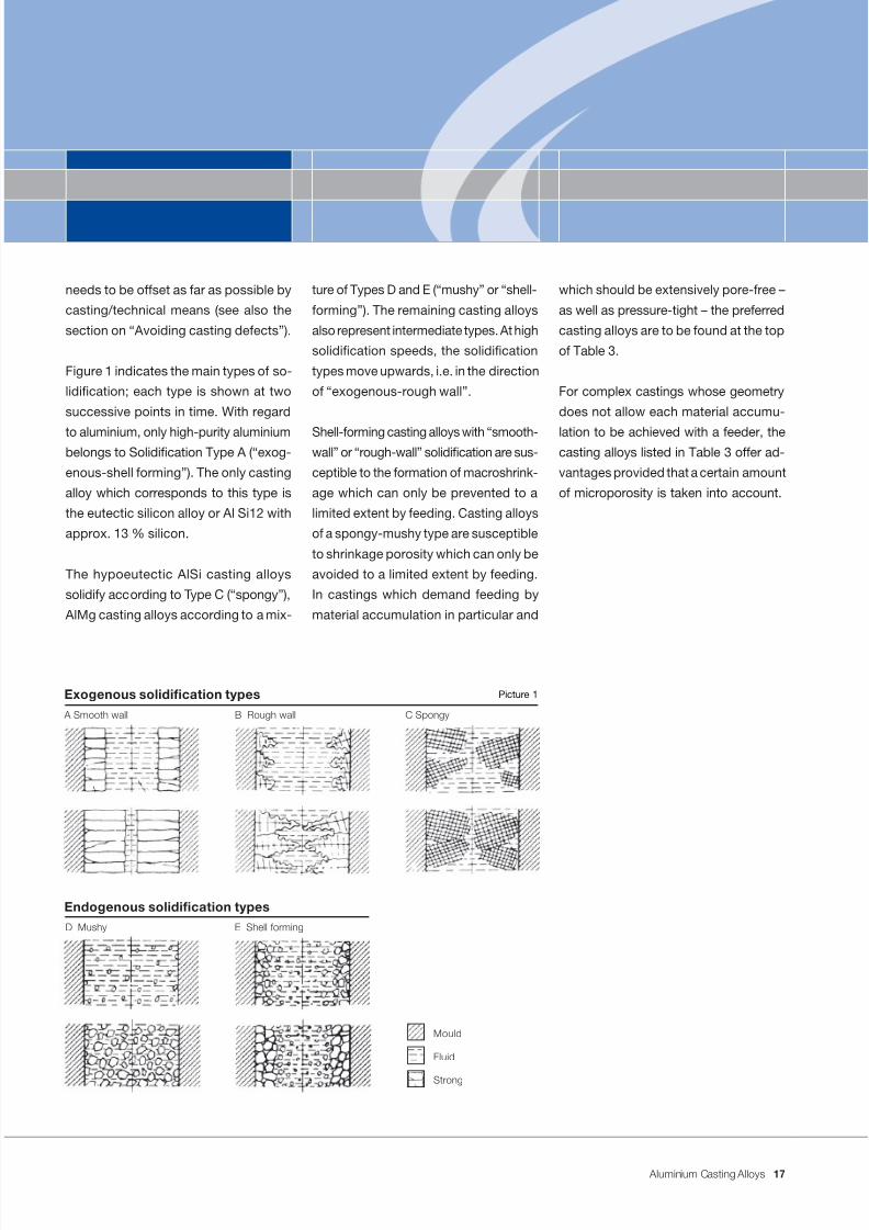
Figure 1 indicates the main types of so-
lidication; each type is shown at two
successive points in time. With regard
to aluminium, only high-purity aluminiumbelongs to Solidication Type A (“exog-
enous-shell forming”). The only casting
alloy which corresponds to this type is
the eutectic silicon alloy or Al Si12 with
approx. 13 % silicon.
The hypoeutectic AlSi casting alloys
solidify according to Type C (“spongy”),
AlMg casting alloys according to a mix-
ture of Types D and E (“mushy” or “shell-
forming”). The remaining casting alloys
also represent intermediate types. At high
solidication speeds, the solidication
types move upwards, i.e. in the direction
of “exogenous-rough wall”.
Shell-forming casting alloys with “smooth-wall” or “rough-wall” solidication are sus-
ceptible to the formation of macroshrink-
age which can only be prevented to a
limited extent by feeding. Casting alloys
of a spongy-mushy type are susceptible
to shrinkage porosity which can only be
avoided to a limited extent by feeding.
In castings which demand feeding by
material accumulation in particular and
which should be extensively pore-free –
as well as pressure-tight – the preferred
casting alloys are to be found at the top
of Table 3.
For complex castings whose geometry
does not allow each material accumu-
lation to be achieved with a feeder, thecasting alloys listed in Table 3 offer ad-
vantages provided that a certain amount
of microporosity is taken into account.
Picture 1
A Smooth wall B Rough wall C Spongy
Exogenous solidication types
D Mushy E Shell forming
Endogenous solidication types
Mould
Fluid
Strong
17
7/31/2019 Aluminium Casting Alloys EnglishVersion 2011
http://slidepdf.com/reader/full/aluminium-casting-alloys-englishversion-2011 18/102
7/31/2019 Aluminium Casting Alloys EnglishVersion 2011
http://slidepdf.com/reader/full/aluminium-casting-alloys-englishversion-2011 19/102
Aluminium Casting Alloys
Inuencing the microstructuralformation of aluminium castings
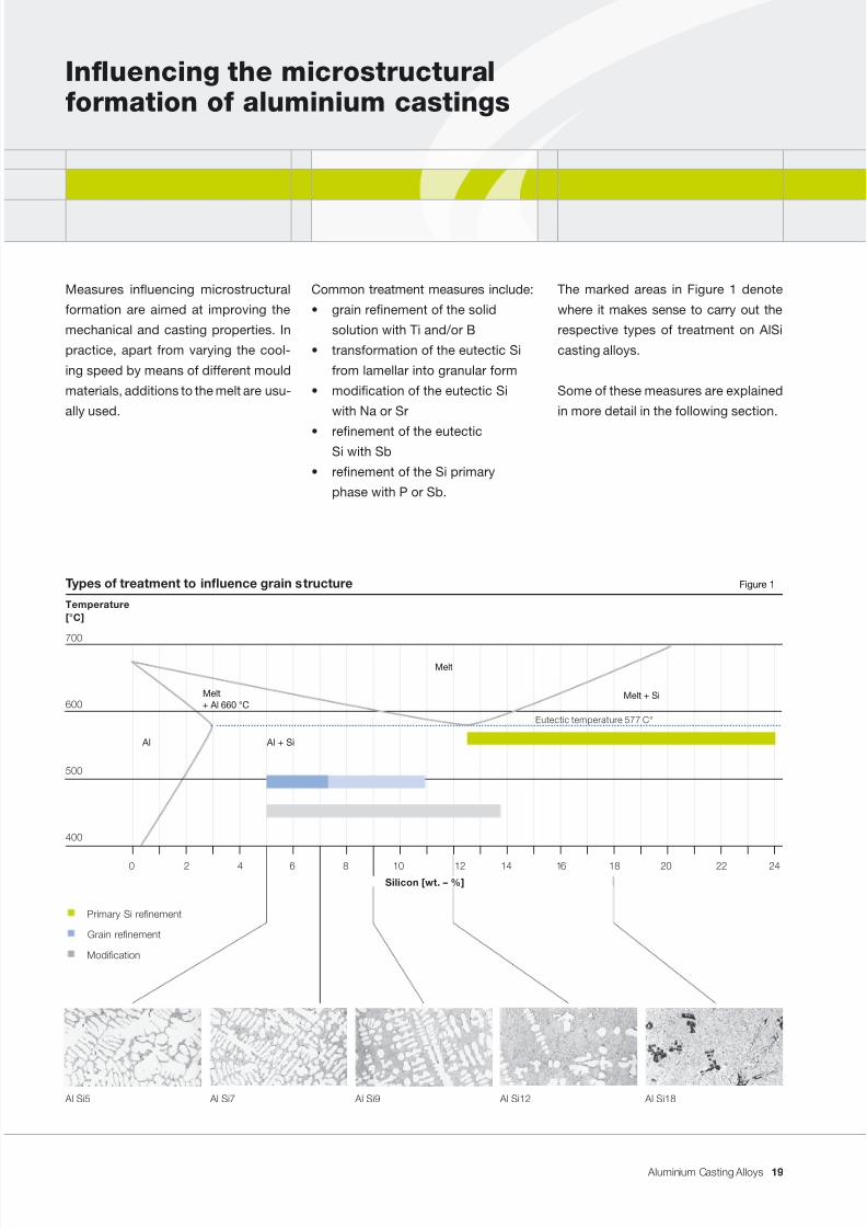
The marked areas in Figure 1 denote
where it makes sense to carry out the
respective types of treatment on AlSi
casting alloys.
Some of these measures are explained
in more detail in the following section.
Common treatment measures include:
• grain renement of the solid
solution with Ti and/or B
• transformation of the eutectic Si
from lamellar into granular form
• modication of the eutectic Si
with Na or Sr
• renement of the eutecticSi with Sb
• renement of the Si primary
phase with P or Sb.
Measures inuencing microstructural
formation are aimed at improving the
mechanical and casting properties. In
practice, apart from varying the cool-
ing speed by means of different mould
materials, additions to the melt are usu-
ally used.
Types of treatment to inuence grain s tructure Figure 1
Temperature[°C]
700
600
500
400
Primary Si renement
Grain renement
0 2 4 6 8 10 12 14 16 18 20 22 24
Modication
Eutectic temperature 577 C°
Melt + Si
Melt
Melt+ Al 660 °C
Al Al + Si
Al Si5 Al Si7 Al Si9 Al Si12 Al Si18
Silicon [wt. – %]
19
7/31/2019 Aluminium Casting Alloys EnglishVersion 2011
http://slidepdf.com/reader/full/aluminium-casting-alloys-englishversion-2011 20/102
Aluminium Casting Alloys
Grain renement
The solidication of many aluminium
casting alloys begins with the formation
of aluminium-rich dendritic or equiaxed
crystals. In the beginning, these solidied
crystallites are surrounded by the remain-
ing melt and, starting from nucleationsites, grow on all sides until they touch
the neighbouring grain or the mould wall.
The characterisation of a grain is the
equiaxed spatial arrangement on the
lattice level. For casting/technical or
optical/decorative reasons as well as
for reasons of chemical resistance, it is
often desirable to set the size of these
grains as uniformly as possible or as nely
as technically possible. To achieve this,
so-called grain renement is f requently
carried out. The idea is to offer the so-
lidifying aluminium as many nucleating
agents as possible.
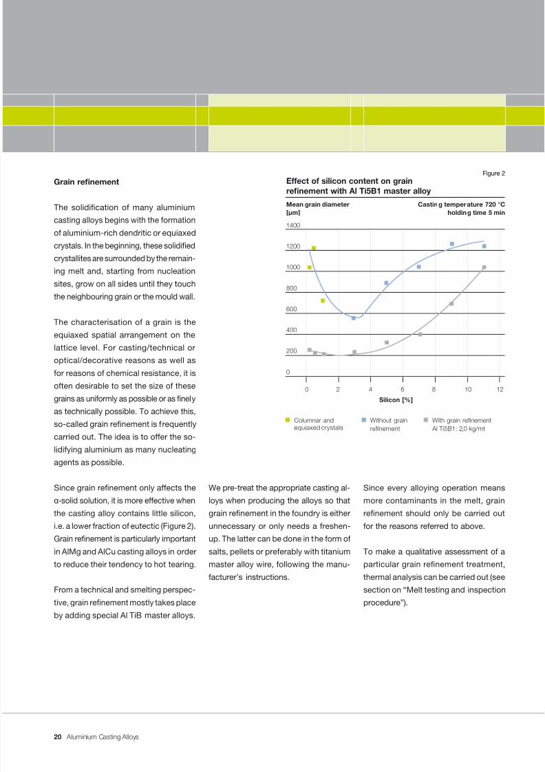
Since grain renement only affects theα -solid solution, it is more effective when
the casting alloy contains little silicon,
i.e. a lower fraction of eutectic (Figure 2).
Grain renement is particularly importantin AlMg and AlCu casting alloys in order
to reduce their tendency to hot tearing.
From a technical and smelting perspec-
tive, grain renement mostly takes place
by adding special Al TiB master alloys.
We pre-treat the appropriate casting al-
loys when producing the alloys so that
grain renement in the foundry is either
unnecessary or only needs a freshen-
up. The latter can be done in the form ofsalts, pellets or preferably with titanium
master alloy wire, following the manu-
facturer’s instructions.
Since every alloying operation means
more contaminants in the melt, grain
renement should only be carried out
for the reasons referred to above.
To make a qualitative assessment of a
particular grain renement treatment,
thermal analysis can be carried out (see
section on “Melt testing and inspection
procedure”).
Effect of silicon content on grainrenement with Al Ti5B1 master alloy
Mean grain diameter Casting temper ature 720 °C[µm] holding time 5 min
1400
1200
1000
800
600
400
200
0
Silicon [%]
Columnar andequiaxed crystals
Without grainrenement
With grain renement Al Ti5B1: 2,0 kg/mt
0 2 4 6 8 10 12
Figure 2
20
7/31/2019 Aluminium Casting Alloys EnglishVersion 2011
http://slidepdf.com/reader/full/aluminium-casting-alloys-englishversion-2011 21/102
Aluminium Casting Alloys
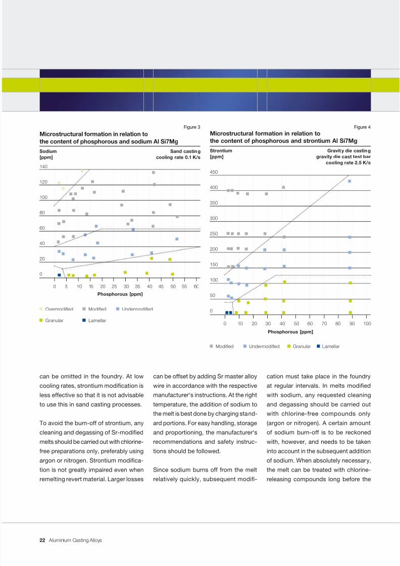
Figures 3 and 4 depict the formation of
microstructural conditions or the degree
of modication as a result of interaction
between sodium and strontium and the
phosphorous element. It can be ascer-
tained that the disruption of modication
due to small amounts of phosphorous
is relatively slight. In Sr modication, ahigh phosphorous content can be offset
by an increased amount of modifying
agent. In aluminium casting alloys with a
silicon content exceeding 7 %, eutectic,
silicon takes up a larger part of the area
of a metallographic specimen. From a
silicon content of approx. 7 to 13 %,
the type of eutectic formation, e.g.
grained or modied, thus plays a key
role in determining the performance
characteristics, especially the ductility
or elongation. When higher elongation is
required in a workpiece, aluminium cast-
ing alloys containing approx. 7 to 13 %
silicon will thus be modied by adding
approx. 0.0040 to 0.0100 % sodium (40
to 100 ppm).
In casting alloys with approx. 11 % silicon,particularly for use in low-pressure die
casting, strontium can also be used as a
long-term modier since the melting loss
behaviour of this element is substantially
better than that of sodium. In this case,
the recommended addition is approx.
0.014 to 0.04 % Sr (140 to 400 ppm).
With suitable casting alloys, the required
amount of strontium can be added
during alloy manufacture so that, as
a rule, the modication process step
Modication of AlSi eutectic
(renement)
By “modication”, we mean the use
of a specic melt treatment to set a
ne-grained eutectic silicon in the cast
structure which improves the mechanical
properties (and elongation in particular)as well as the casting properties in many
cases. As a general rule, modication
is carried out by adding small amounts
of sodium or strontium. To facilitate an
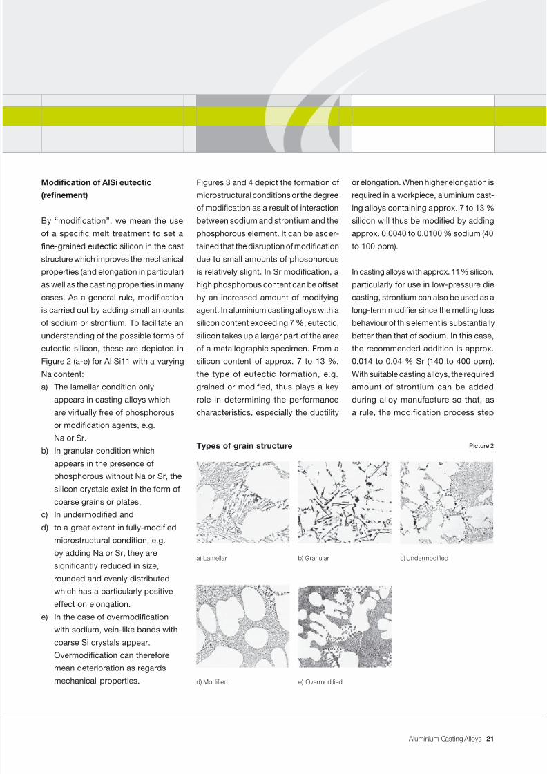
understanding of the possible forms of
eutectic silicon, these are depicted in
Figure 2 (a-e) for Al Si11 with a varying
Na content:
a) The lamellar condition only
appears in casting alloys which
are virtually free of phosphorous
or modication agents, e.g.
Na or Sr.
b) In granular condition which
appears in the presence of
phosphorous without Na or Sr, the
silicon crystals exist in the form of
coarse grains or plates.
c) In undermodied and
d) to a great extent in fully-modied
microstructural condition, e.g.by adding Na or Sr, they are
signicantly reduced in size,
rounded and evenly distributed
which has a particularly positive
effect on elongation.
e) In the case of overmodication
with sodium, vein-like bands with
coarse Si crystals appear.
Overmodication can therefore
mean deterioration as regards
mechanical properties.
a) Lamellar b) Granular
e) Overmodied
c) Undermodied
d) Modied
Picture 2Types of grain structure
21
7/31/2019 Aluminium Casting Alloys EnglishVersion 2011
http://slidepdf.com/reader/full/aluminium-casting-alloys-englishversion-2011 22/102
Aluminium Casting Alloys
can be omitted in the foundry. At low
cooling rates, strontium modication is
less effective so that it is not advisableto use this in sand casting processes.
To avoid the burn-off of strontium, any
cleaning and degassing of Sr-modied
melts should be carried out with chlorine-
free preparations only, preferably using
argon or nitrogen. Strontium modica-
tion is not greatly impaired even when
remelting revert material. Larger losses
can be offset by adding Sr master alloy
wire in accordance with the respective
manufacturer‘s instructions. At the righttemperature, the addition of sodium to
the melt is best done by charging stand-
ard portions. For easy handling, storage
and proportioning, the manufacturer‘s
recommendations and safety instruc-
tions should be followed.
Since sodium burns off from the melt
relatively quickly, subsequent modi-
cation must take place in the foundry
at regular intervals. In melts modied
with sodium, any requested cleaningand degassing should be carried out
with chlorine-free compounds only
(argon or nitrogen). A certain amount
of sodium burn-off is to be reckoned
with, however, and needs to be taken
into account in the subsequent addition
of sodium. When absolutely necessary,
the melt can be treated with chlorine-
releasing compounds long before the
Phosphorous [ppm]
Overmodied
Granular
Modied
Lamellar
Undermodied
Microstructural formation in relation tothe content of phosphorous and sodium Al Si7Mg
Sodium Sand casting[ppm] cooling rate 0.1 K/s
140
120
100
80
60
40
20
0
0 5 10 15 20 25 30 35 40 45 50 55 60
Figure 3
Phosphorous [ppm]
Modied Undermodied Granular Lamellar
Microstructural formation in relation tothe content of phosphorous and strontium Al Si7Mg
Strontium Gravit y die casting[ppm] gravity die cast test bar
cooling rate 2.5 K/s
450
400
350
300
250
200
150
100
50
0
0 10 20 30 40 50 60 70 80 90 100
Figure 4
22
7/31/2019 Aluminium Casting Alloys EnglishVersion 2011
http://slidepdf.com/reader/full/aluminium-casting-alloys-englishversion-2011 23/102
Aluminium Casting Alloys
rst addition of sodium. If such treat-
ment is carried out after adding sodium
or strontium, chlorine may react with
these elements and remove them from
the melt, thereby preventing any further
modication.
Modication with sodium or strontiumincreases the tendency to gas absorp-
tion in the melt. As a result of the reac-
tion of the precipitating hydrogen with
the rapidly-forming oxides, defects can
occur in the casting, especially cumulant
microporosity. In many practical cases,
this potential for micropore formation
is even desirable. Then, the purpose
of modification is also to offset the
expected macroshrinkage by forming
many micropores.
An accurate assessment of the effects
of modication can only be made by
means of metallographic examination.
As a quick test, thermal analysis can be
carried out if it is possible to establish by
means of a preliminary metallographic
examination which depression value is
necessary to attain a sufciently-modi-
ed grain structure (for more informationon thermal analysis, please refer to the
section on “Methods for monitoring the
melt”). Under the same conditions, rapid
determination of the modied condition
is also possible by measuring the elec-
trical conductance of a sample.
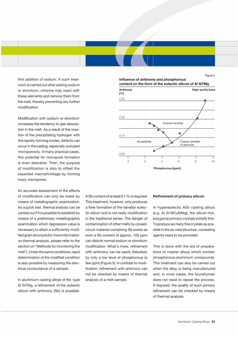
In aluminium casting alloys of the type
Al Si7Mg, a renement of the eutectic
silicon with antimony (Sb) is possible.
A Sb content of at least 0.1 % is required.
This treatment, however, only produces
a ner formation of the lamellar eutec-
tic silicon and is not really modication
in the traditional sense. The danger of
contamination of other melts by closed-
circuit material containing Sb exists as
even a Sb content of approx. 100 ppmcan disturb normal sodium or strontium
modication. What‘s more, renement
with antimony can be easily disturbed
by only a low level of phosphorous (a
few ppm) (Figure 5). In contrast to modi-
cation, renement with antimony can
not be checked by means of thermal
analysis of a melt sample.
Renement of primary silicon
In hypereutectic AlSi casting alloys
(e.g. Al Si18CuNiMg), the silicon-rich,
polygonal primary crystals solidify rst.
To produce as many ne crystals as pos-
sible in the as-cast structure, nucleating
agents need to be provided.
This is done with the aid of prepara-
tions or master alloys which contain
phosphorous-aluminium compounds.
This treatment can also be carried out
when the alloy is being manufactured
and, in most cases, the foundryman
does not need to repeat the process.
If required, the quality of such primary
renement can be checked by means
of thermal analysis.
Phosphorous [ppm]
Inuence of antimony and phosphorouscontent on the form of the eutectic silicon of Al Si7Mg
Antimony[%]
0.30
0.20
0.10
0.00
0 2 4 6 8 10
Coarse-lamellar
Acceptable Coarse- lamellarto granular
High-purity base
Figure 5
23
7/31/2019 Aluminium Casting Alloys EnglishVersion 2011
http://slidepdf.com/reader/full/aluminium-casting-alloys-englishversion-2011 24/102
7/31/2019 Aluminium Casting Alloys EnglishVersion 2011
http://slidepdf.com/reader/full/aluminium-casting-alloys-englishversion-2011 25/102
Aluminium Casting Alloys
Avoiding impurities
Ingot quality
An essent ial prerequisite for a good
casting is good ingot quality. The metal
should be cleaned effectively and the in-
gots should display neither metallic nornon-metallic inclusions. The ingots must
be dry (there is a risk of explosion when
damp) and no oil or paint residue should
be present on their surface. When using
revert material, this should be in lumps,
if possible, and well cleaned.
Melting
When melting ingots or revert material,
it must be ensured that the metal is not
exposed unnecessarily to the ame or
furnace atmosphere. The pieces of metal
should be melted down swiftly, i.e. follow-
ing short preheating, immersed directlyin the liquid melt.
Large-volume hearth or crucible furnaces
are best suited to melting. Furnaces with
melting bridges are oxide producers and
they lead to expensive, unnecessary and
irretrievable metal losses.
The type and state of the melt in contact
with refractory materials are of particular
importance in the melting and holding
of aluminium.
Aluminium and aluminium casting alloys
in a molten state are very aggressive, es-
pecially when AlSi melts contain sodium
or strontium as modifying agents. With
an eye to quality, reactions, adherences,
inltrations, abrasive wear and decompo-
sition have to be kept within limits when
using melting crucibles and refractorymaterials as well as during subsequent
processing. The care and maintenance
as well as cleanliness of equipment are
equally important. Adhering materials
can very easily lead to the undesired
redissolving of oxides in the melt and
cause casting defects.
Melting temperature
The temperature of the melt must be set
individually for each alloy.
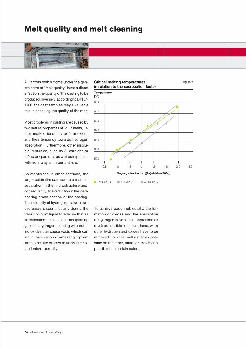
Too low melting temperatures lead to
longer residence times and, as a result,
to greater oxidation of the pieces jut-ting out of the melt. The melt becomes
homogeneous too slowly, i.e. local un-
dercooling allows segregation to take
place, even as far as tenacious gravity
segregation of the FeMnCrSi type phases.
The mathematical interrelationship for
the segregation of heavy intermetallic
phases is depicted in Figure 6.
Furthermore, at too low temperatures,
autopurication of the melt (oxides ris-
ing) can not take place.
When the temperature of the melt is too
high, increased oxide formation and
gassing can occur. Lighter alloying ele-
ments, e.g. magnesium, are subject to
burn-off in any case; this must be off-
set by appropriate additions. Too high
melting temperatures aggravate this loss
by burning.
25
7/31/2019 Aluminium Casting Alloys EnglishVersion 2011
http://slidepdf.com/reader/full/aluminium-casting-alloys-englishversion-2011 26/102
Aluminium Casting Alloys
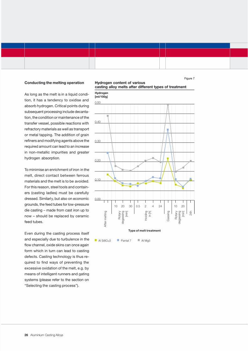
Conducting the melting operation
As long as the melt is in a liquid condi-
tion, it has a tendency to oxidise and
absorb hydrogen. Critical points during
subsequent processing include decanta-
tion, the condition or maintenance of the
transfer vessel, possible reactions withrefractory materials as well as transport
or metal tapping. The addition of grain
reners and modifying agents above the
required amount can lead to an increase
in non-metallic impurities and greater
hydrogen absorption.
To minimise an enrichment of iron in the
melt, direct contact between ferrous
materials and the melt is to be avoided.
For this reason, steel tools and contain-
ers (casting ladles) must be carefully
dressed. Similarly, but also on economic
grounds, the feed tubes for low-pressure
die casting – made from cast iron up to
now – should be replaced by ceramic
feed tubes.
Even during the casting process itself
and especially due to turbulence in the
ow channel, oxide skins can once againform which in turn can lead to casting
defects. Casting technology is thus re-
quired to nd ways of preventing the
excessive oxidation of the melt, e.g. by
means of intelligent runners and gating
systems (please refer to the section on
“Selecting the casting process”).
Type of melt treatment
Al Si8Cu3 Pantal 7 Al Mg5
Hydrogen content of variouscasting alloy melts after different types of treatment
Hydrogen[ml/100g]
0.50
0.40
0.30
0.20
0.10
0.00
10 20 30 0.5 2 4 24 10 20
A f t e r m e
l t i n g
R o
t a r y
d e g a s s i n g
[ m i n ]
R o
t a r y
d e g a s s i n g
[ m i n ]
G a s s i n g
2 4 h
H o
l d i n g
i n [ h ]
Figure 7
26
7/31/2019 Aluminium Casting Alloys EnglishVersion 2011
http://slidepdf.com/reader/full/aluminium-casting-alloys-englishversion-2011 27/102
Aluminium Casting Alloys
Cleaning and degassing the melt
Our casting alloys consist of effectively
cleaned metal. Since reoxidation always
takes place during smelting, and in
practice revert material is always used,
a thorough cleaning of the melt is nec-
essary prior to casting.
Holding the aluminium melt at the cor-
rect temperature for a long time is an ef-
fective cleaning method. It is, however,
very time-intensive and not carried out
that often as a result. Foundrymen are
thus left with only intensive methods, i.e.
using technical equipment or the usual
commercially available mixture of salts.
In principle, melt cleaning is a physical
process: the gas bubbles rising through
the liquid metal attach oxide lms to their
outer surfaces and allow hydrogen to dif-
fuse into the bubbles from the melt. Both
are transported to the bath surface by the
bubbles. It is therefore clear that in order
for cleaning of the melt to be effective, it
is desirable to have as many small gas
bubbles as possible distributed across
the entire cross-section of the bath.
Dross can be removed from the surface
of the bath, possibly with the aid of ox-
ide-binding salts.
Inert-gas ushing by means of an im-
peller is a widely-used, economical and
environmentally-sound cleaning process.
The gas stream is dispersed in the formof very small bubbles by the rapid turn-
ing of a rotor and, in conjunction with the
good intermixing of the melt, this leads
to very efcient degassing. To achieve
an optimum degassing effect, the vari-
ous parameters such as rotor diameter
and revolutions per minute, gas ow
rate, treatment time, geometry and size
of the crucible used as well as the alloy,
have to be co-ordinated. The course of
degassing and reabsorption of hydrogen
is depicted for various casting alloys
in Figure 7.
When using commercially available salt
preparations, the manufacturer‘s instruc-
tions concerning use, proportioning,
storage and safety should be followed.
Apart from this, attention should also be
paid to the quality and care of tools and
auxiliary materials used for cleaning so
that the cleaning effect is not impaired.
If practically feasible, it is also possible
to lter the melt using a ceramic foam
lter. In the precision casting of high-grade castings, especially in the sand
casting process, the use of ceramic
lters in the runner to the sand mould
has proved to be a success. Above all,
such a lter leads to an even ow and
can retain coarse impurities and oxides.
In the gravity die casting of sensitive
hydraulic parts, or when casting sub-
sequently anodised decorative ttings
in Al Mg3, ladling out of a device which
is tted with in-line lter elements and
separated from the remaining melt bath
is very common.
27
7/31/2019 Aluminium Casting Alloys EnglishVersion 2011
http://slidepdf.com/reader/full/aluminium-casting-alloys-englishversion-2011 28/102
Aluminium Casting Alloys
Melt testing and inspection procedure
To assess the effectiveness of the clean-
ing process or the quality of the melt, the
following test and inspection methods
can be used to monitor the melt:
Reduced pressure test
This method serves to determine the
tendency to pore formation in the melt
during solidication. A sample, which
can contain a varying number of gas
bubbles depending on the gas content,
is allowed to solidify at an underpressure
of 80 mbar. The apparent density is then
compared with that of a sample which
is solidied at atmospheric pressure.
The so-called “Density Index” is then
calculated using the following equation:
DI = (dA - d80)/dA x 100 %
DI = Density Index
dA = density of the sample solidied
at atmospheric pressure
d80 = density of the sample solidied
at under 80 mbar
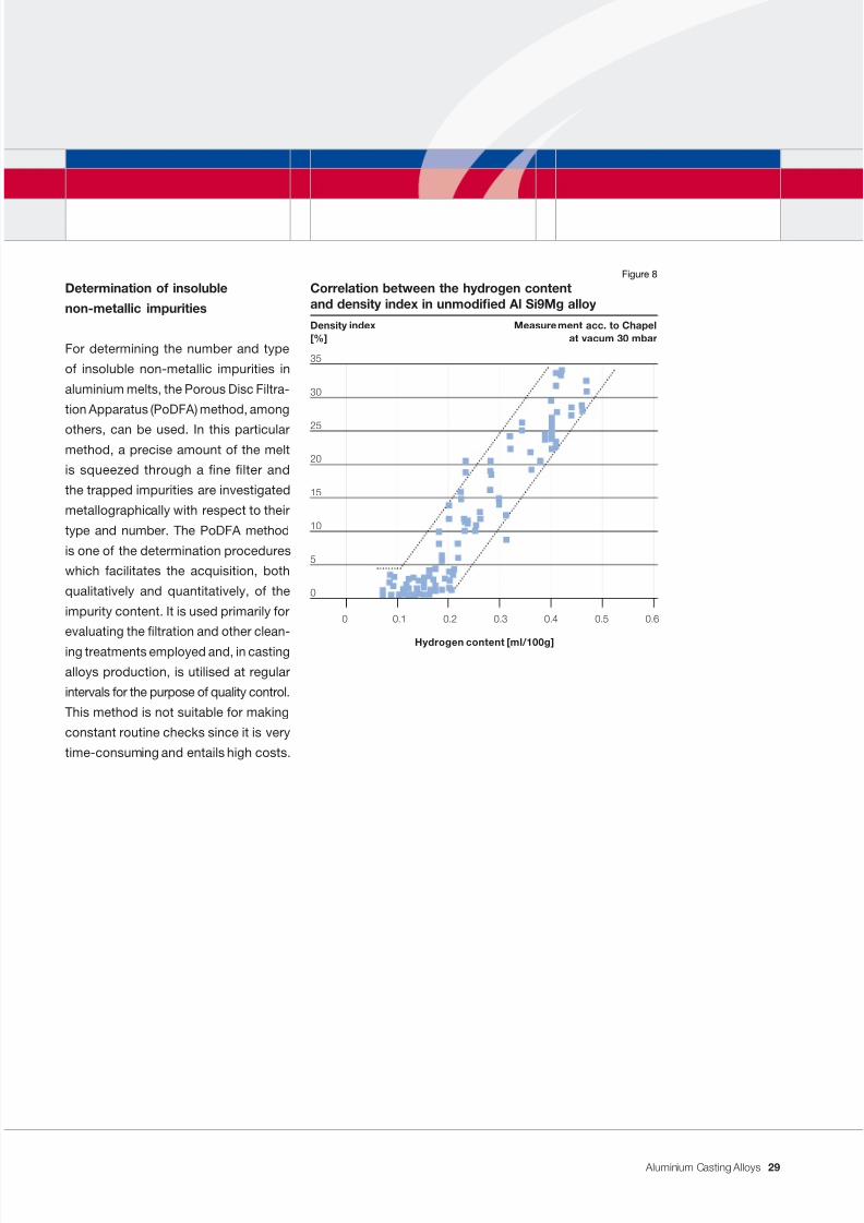
The Density Index allows a certain infer-
ence to be drawn about the hydrogen
content of the melt. It is, however, strongly
inuenced by the alloying elements and,
above all, by varying content of impurities
so that the hydrogen content must not
on any account be stated as a Density
Index value (Figure 8).
The assessment of melt quality by means
of an underpressure density sample there-
fore demands the specic determination
of a critical Density Index value for each
casting alloy and for each application.
The underpressure density method is,
however, a swift and inexpensive meth-
od with the result that it is already used
in many foundries for quality control.
To keep results comparable, sampling
should always be carried out according
to set parameters.
Determination of the hydrogen
content in the melt
Reliable instruments have been in opera-
tion for years for measuring the hydrogen
content in aluminium melts. They work
according to the principle of establish-
ing equilibration between the melt and ameasuring probe so that the actual gas
content in the melt is determined and not
in the solid sample. In this way, the effec-
tiveness of the degassing treatment can
be assessed quickly. The procurement of
such an instrument for continuous quality
monitoring is only worthwhile when it is
used frequently; in small foundries, the
hiring of an instrument to solve problems
is sufcient.
28
7/31/2019 Aluminium Casting Alloys EnglishVersion 2011
http://slidepdf.com/reader/full/aluminium-casting-alloys-englishversion-2011 29/102
Aluminium Casting Alloys
Determination of insoluble
non-metallic impurities
For determining the number and type
of insoluble non-metallic impurities in
aluminium melts, the Porous Disc Filtra-
tion Apparatus (PoDFA) method, among
others, can be used. In this particularmethod, a precise amount of the melt
is squeezed through a ne lter and
the trapped impurities are investigated
metallographically with respect to their
type and number. The PoDFA method
is one of the determination procedures
which facilitates the acquisition, both
qualitatively and quantitatively, of the
impurity content. It is used primarily for
evaluating the ltration and other clean-
ing treatments employed and, in casting
alloys production, is utilised at regular
intervals for the purpose of quality control.
This method is not suitable for making
constant routine checks since it is very
time-consuming and entails high costs.
Hydrogen content [ml/100g]
Correlation between the hydrogen contentand density index in unmodied Al Si9Mg alloy
Density index Measurement acc. to Chapel[%] at vacum 30 mbar
35
30
25
20
15
10
5
0
0 0.1 0.2 0.3 0.4 0.5 0.6
Figure 8
29
7/31/2019 Aluminium Casting Alloys EnglishVersion 2011
http://slidepdf.com/reader/full/aluminium-casting-alloys-englishversion-2011 30/102
Aluminium Casting Alloys
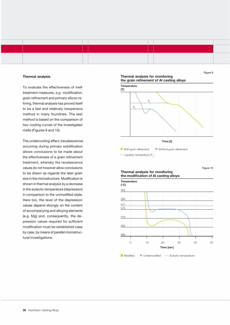
Thermal analysis
To evaluate the effectiveness of melt
treatment measures, e.g. modication,
grain renement and primary silicon re-
ning, thermal analysis has proved itself
to be a fast and relatively inexpensive
method in many foundries. The testmethod is based on the comparison of
two cooling curves of the investigated
melts (Figures 9 and 10).
The undercooling effect (recalescence)
occurring during primary solidication
allows conclusions to be made about
the effectiveness of a grain renement
treatment, whereby the recalescence
values do not however allow conclusions
to be drawn as regards the later grain
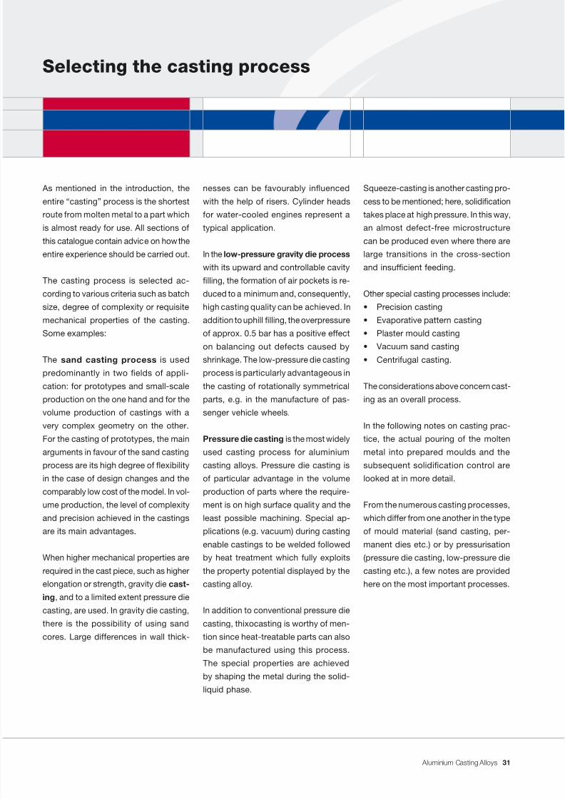
size in the microstructure. Modication is
shown in thermal analysis by a decrease
in the eutectic temperature (depression)
in comparison to the unmodied state.
Here too, the level of the depression
values depend strongly on the content
of accompanying and alloying elements
(e.g. Mg) and, consequently, the de-
pression values required for sufcient
modication must be established caseby case, by means of parallel microstruc-
tural investigations.
Time [t]
Thermal analysis for monitoringthe grain renement of Al casting alloys
Temperature[T]
With grain renement Without grain renement
Liquidus temperature [T L]
TL
TL
Figure 9
Time [sec]
Thermal analysis for monitoringthe modication of Al casting alloys
Temperature[°C]
585
580
577575
570
565
560
0 10 20 30 40 50
Modied Undermodied Eutectic temperature
Figure 10
30
7/31/2019 Aluminium Casting Alloys EnglishVersion 2011
http://slidepdf.com/reader/full/aluminium-casting-alloys-englishversion-2011 31/102
Aluminium Casting Alloys
Selecting the casting process
Squeeze-casting is another casting pro-
cess to be mentioned; here, solidication
takes place at high pressure. In this way,
an almost defect-free microstructure
can be produced even where there are
large transitions in the cross-section
and insufcient feeding.
Other special casting processes include:
• Precision casting
• Evaporative pattern casting
• Plaster mould casting
• Vacuum sand casting
• Centrifugal casting.
The considerations above concern cast-
ing as an overall process.
In the following notes on casting prac-
tice, the actual pouring of the molten
metal into prepared moulds and the
subsequent solidication control are
looked at in more detail.
From the numerous casting processes,
which differ from one another in the type
of mould material (sand casting, per-
manent dies etc.) or by pressurisation
(pressure die casting, low-pressure diecasting etc.), a few notes are provided
here on the most important processes.
nesses can be favourably inuenced
with the help of risers. Cylinder heads
for water-cooled engines represent a
typical application.
In the low-pressure gravity die process
with its upward and controllable cavity
lling, the formation of air pockets is re-duced to a minimum and, consequently,
high casting quality can be achieved. In
addition to uphill lling, the overpressure
of approx. 0.5 bar has a positive effect
on balancing out defects caused by
shrinkage. The low-pressure die casting
process is particularly advantageous in
the casting of rotationally symmetrical
parts, e.g. in the manufacture of pas-
senger vehicle wheels.
Pressure die casting is the most widely
used casting process for aluminium
casting alloys. Pressure die casting is
of particular advantage in the volume
production of parts where the require-
ment is on high surface quality and the
least possible machining. Special ap-
plications (e.g. vacuum) during casting
enable castings to be welded followed
by heat treatment which fully exploitsthe property potential displayed by the
casting alloy.
In addition to conventional pressure die
casting, thixocasting is worthy of men-
tion since heat-treatable parts can also
be manufactured using this process.
The special properties are achieved
by shaping the metal during the solid-
liquid phase.
As mentioned in the introduction, the
entire “casting” process is the shortest
route from molten metal to a part which
is almost ready for use. All sections of
this catalogue contain advice on how the
entire experience should be carried out.
The casting process is selected ac-cording to various criteria such as batch
size, degree of complexity or requisite
mechanical properties of the casting.
Some examples:
The sand casting process is used
predominantly in two elds of appli-
cation: for prototypes and small-scale
production on the one hand and for the
volume production of castings with a
very complex geometry on the other.
For the casting of prototypes, the main
arguments in favour of the sand casting
process are its high degree of exibility
in the case of design changes and the
comparably low cost of the model. In vol-
ume production, the level of complexity
and precision achieved in the castings
are its main advantages.
When higher mechanical properties arerequired in the cast piece, such as higher
elongation or strength, gravity die cast-
ing , and to a limited extent pressure die
casting, are used. In gravity die casting,
there is the possibility of using sand
cores. Large differences in wall thick-
31
7/31/2019 Aluminium Casting Alloys EnglishVersion 2011
http://slidepdf.com/reader/full/aluminium-casting-alloys-englishversion-2011 32/102
Aluminium Casting Alloys
Gravity die casting process
The gravity die casting which includes
the well-known low-pressure die casting
process is applied. The main elds of
application are medium- or high-volume
production using high-grade alloys, and
also low to medium component weightusing heat-treatable alloys. Compared
with sand casting, the aluminium cast-
ings display very good microstructural
properties as well as good to very good
mechanical properties which result from
the rapid cooling times and the other
easily-controlled operating parameters.
The castings have high dimensional ac-
curacy and stability as well as a good
surface nish, are heat-treatable and
can also be anodised.
The basis for good quality castings is,
not least, the right melt treatment and
the appropriate casting temperature (see
section on “Melt quality and melt clean-
ing”). For castings with high surface or
microstructural quality requirements,
such as in decorative or subsequently
anodised components or in pressure-tight hydraulic parts, it is useful to lter
the melt before casting.
Parts generated using the horizontal
pressure die casting process are light-
weight as low wall thicknesses can be
achieved. They have a good surface
nish, high dimensional accuracy and
only require a low machining allowance
in their design. Many bore holes can be
pre-cast.
The melting and casting temperatures
should not be too low and should be
checked constantly. Pre-melting alu-
minium casting alloys is useful. The melt
can thus be given a good clean in order
to keep the melt homogeneous and to
avoid undesirable gravity segregation
(see Figure 6). From a statistical point
of view, more casting defects arise from
cold metal than from hot. It is particu-
larly important to keep a sufciently high
melting temperature, even with hypere-
utectic alloys. These comments are also
valid for other casting processes.
Pressure die casting process
This process takes up the largest share.
The hydraulically-controlled pressure
die casting machine and the in-built
die make up the central element of the
process. The performance, the precise
control of the hydraulic machine, thequality of the relatively expensive tools
made from hot work steel are the deci-
sive factors in this process. In contrast,
the ow properties and solidication
of the aluminium casting alloys play a
rather subordinate role in this “forced”
casting process.
The pouring operation in horizontal pres-
sure die casting begins with the casting
chamber being lled with metal. The
rst movement, i.e. the slow advance of
the plunger and the consequent pile-up
of metal until the sleeve is completely
lled, is the most important operation.
In doing this, no ashover of the metal
or other turbulence may occur until all of
the air in the sleeve has been squeezed
out. Immediately afterwards, the actual
casting operation begins with the rapid
casting phase. High injection pressure isessential to achieve high ow velocities
in the metal. In this way, the die can be
lled in a few hundredths of a second.
Throughout the casting operation, the
liquid metal streams are subject to the
laws of hydrodynamics. Sharp turns
and collisions with the die walls lead
to a clear division of the metal stream.
32
7/31/2019 Aluminium Casting Alloys EnglishVersion 2011
http://slidepdf.com/reader/full/aluminium-casting-alloys-englishversion-2011 33/102
Aluminium Casting Alloys
Demands on the casting system
To keep disadvantages and defects –
which constantly arise from an oxide
skin forming on the melt – within limits,
the gating system must guarantee low
turbulence in the metal stream and also
a smooth, controlled lling of the diecavity. With the transition from a liquid
to a solid condition, volume contraction
occurs; this can amount to up to 7 %
of the volume. This shrinkage is con-
trollable when the solid-liquid interface
runs – controlled or directed – through
the casting, mostly from the bottom to
the top. This task, namely to effect a
directed solidication, can be achieved
with a good pouring system.
The castings are usually arranged “up-
right” in the die. The greatest mass can
thus be placed in the bottom of the die.
Quality requirements can be, for example,
high strength, high-pressure tightness or
decorative anodising quality.
One example of an “ideal” gating systemwhich meets the highest casting require-
ments is the so-called “slit gate system”.
Here, the metal is conducted upwards
continuously or discontinuously to the
casting via a main runner. During mould
lling, the melt is thus superimposed layer
upon layer with the hotter metal always
owing over the already solidifying metal.
The standpipe ends in the top riser and
supplies it with hot metal. This way, the
solidication can be directed from below,
possibly supported by cooling, towards
the top running through the casting and
safeguarding the continuous supply of
hot metal. When there is a wide are in
the casting, the gating system has to be
laid out on both sides. This symmetry en-
sures a division of the metal and also an
even distribution of the heat in the die.
In low-pressure die casting, directing
the solidication by means of the gat-
ing system is not possible. Nor is there
any great possibility of classic feeding.
Directional solidication is only possible
by controlling the thermal balance of the
die during casting. This mostly requires
the installation of an expensive cooling-heating system.
Simulation calculations for die lling and
solidication can be useful when laying
out and designing the die and possibly
the cooling. In actual production, the
cooling and cycle time can be optimised
by means of thermography (see section
on “Solidication simulation and ther-
mography”).
33
7/31/2019 Aluminium Casting Alloys EnglishVersion 2011
http://slidepdf.com/reader/full/aluminium-casting-alloys-englishversion-2011 34/102
7/31/2019 Aluminium Casting Alloys EnglishVersion 2011
http://slidepdf.com/reader/full/aluminium-casting-alloys-englishversion-2011 35/102
Aluminium Casting Alloys
Casting-compliant design
Only through good cast quality can the
technical requirements be met and the
full potential of the casting alloy be ex-
ploited. Every effort and consideration
must be made therefore to design a light,
functionally efcient part whose manu-
facture and machining can be carried out
as efciently as possible. For this andsubsequent considerations, the use of
solidication simulation is available (see
section on “Solidication simulation and
thermography”).
Casting alloys shrink during solidica-
tion, i.e. their volume is reduced. This
increases the risk of defects in the cast
structure, such as cavities, pores or
shrinkage holes, tears or similar. The
most important requirement is thus to
avoid material accumulations by hav-
ing as even a wall thickness as possible.
In specialist literature, the following lower
limits for wall thickness are given:
• Sand castings: 3-4 mm
• Gravity die castings: 2-3 mm
• Pressure die castings: 1-1.5 mm.
In the valid European standard, DIN EN
1706 for aluminium castings, there are
strength values only for separately-cast
bars using sand and gravity die casting.
For samples cut from the cast piece,
a reduction in the 0.2 % proof stress
and ultimate tensile strength values of
up to 70 % and a decrease in elonga-tion of up to 50 % from the test bar can
be anticipated. When the alloy and the
casting process are specied, so too is
the next point within the framework of
the design, i.e. determination of the die
parting line. Die parting on one level is
not only the cheapest for patterns and
dies but also for subsequent working and
machining. Likewise, every effort should
be made to produce a casting without
undercuts. This is followed by designing
and determining the actual dimensions
of the part. The constant guideline must
be to achieve a defect-free cast structure
wherever possible.
The following notes on the design of
aluminium castings are provided to help
exploit in full the advantages and design
possibilities of near net shape casting.
They also align practical requirements
with material suitability.
Aluminium casting alloys can be pro-cessed in practically all conventional
casting processes, whereby pressure die
casting accounts for the largest volume,
followed by gravity die casting and sand
casting. The most useful casting process
is not only dependent on the number and
weight of pieces but also on other tech-
nical and economic conditions (see sec-
tion on “Selecting the casting process”).
To nd the optimum solution and produce
a light part as cheaply and rationally as
possible, co-operation between the de-
signer, caster and materials engineer is
always necessary. Knowledge concern-
ing the loads applied, the distribution of
stress, the range of chemical loading and
operation temperatures is important.
35
7/31/2019 Aluminium Casting Alloys EnglishVersion 2011
http://slidepdf.com/reader/full/aluminium-casting-alloys-englishversion-2011 36/102
7/31/2019 Aluminium Casting Alloys EnglishVersion 2011
http://slidepdf.com/reader/full/aluminium-casting-alloys-englishversion-2011 37/102
Aluminium Casting Alloys
Solidication simulation and thermography
Thermography
Even after a casting goes into volume
production, it is often desirable and nec-
essary to optimise the casting process
and increase process stability. Besides
the aforementioned solidication simula-
tion, periodic thermal monitoring of thedies by means of thermography is used
in particular.
In this process, a thermogramme of the
die or casting to be investigated is made
with the aid of an infrared camera. This
way, the effectiveness of cooling, e.g. in
pressure or gravity die casting, can be
checked or optimised and the optimum
time for lifting determined.
Possible positive effects of simulation
calculations include:
• Optimisation of the casting before
casting actually takes place
• Avoiding casting defects
• Optimisation of the feeding system
(reducing material in the recycling
circuit)• Optimisation of the casting
process (reducing cycle times)
• Increasing process stability
• Visualisation of the die-lling and
solidication process.
A simulation programme does not opti-
mise on its own and can not, and should
not, replace the experienced foundry-
man. To exploit the potential of die-lling
and solidication simulation to the full,
it should be applied as early as possi-
ble, i.e. already at the design stage of
the casting.
Solidication simulation
A basic aim in the manufacture of cast-
ings is to avoid casting defects while
minimising the amount of material in the
recycling circuit.
Optimisation of the manufacture of cast-ings with regard to casting geometry,
gating and feeding system and cast-
ing parameters can be achieved via
numerical simulation of die lling and
the mechanisms of solidication on the
computer. Casting defects can thus be
detected in good time and the casting
design and casting system optimised
before the rst casting operation takes
place. In principle, ow and thermal con-
duction phenomena which occur during
casting can be calculated numerically
using simulation programmes.
In calculation models, the casting and
die geometry – which rst of all must be
available in a CAD volume model – is thus
divided into small volume elements (Finite
Difference Method). The ow velocities
and temperatures in the individual vol-
ume elements are then calculated usinga numerical method.
37
7/31/2019 Aluminium Casting Alloys EnglishVersion 2011
http://slidepdf.com/reader/full/aluminium-casting-alloys-englishversion-2011 38/102
Aluminium Casting Alloys
Avoiding casting defects
The type of solidication is also impor-
tant when considering suitable casting/
technical measures. In AlSi casting al-
loys with approx. 13 % Si, a frozen shell
forms during solidication while, in hy-
poeutectic AlSi casting alloys as well
as in AlMg and AlCu casting alloys, a
predominantly dendritic or globular so-lidication occurs.
In gravity die casting processes, the
feeders are laid out in particularly critical
or thick areas of the casting. The feed-
ers require hot metal in appropriately
large volumes to execute their task. The
combination of feeding and cooling is
useful. Heat removal to accelerate and
control solidication at the lower end
of the casting or in solid areas can be
effected by means of metal plates or
surface chills (cooling elements).
quality and melt cleaning” as well as
“Methods for melt monitoring” and “Se-
lecting the casting process”. Here are a
few key points:
• Use good quality ingots
• Quality-oriented melting technology
and equipment
• Correct charging of the ingots(dry, rapid melting)
• Temperature control during
melting and casting
• Melt cleaning and melt control
• Safety measures during treatment,
transport and casting
Volume contraction during the transition
from liquid to solid state can - depend-
ing on the casting alloy - be up to 7 %
volume. Under unfavourable conditions,
part of this volume difference can be the
cause of defects in castings, e.g. shrink
marks, shrink holes, pores or tears. To
produce a good casting, the possibility
of feeding additional molten metal into
the contracting microstructure during
solidication must exist. In pressure
casting processes, this occurs by means
of pressurisation; in gravity die casting,
this is done primarily by feeding.
As shown in Table 4, there are two
phenomena which – individually or in
combination – can lead to defects in
emergent castings:
1. The continuous (new) formation of
oxides in the liquid state and
2. volume contraction during the trans-
ition from liquid to solid state.
During transition from liquid to solid
state, the dissolved hydrogen in the melt
precipitates and, on interacting with ox-
ides, causes the well-known problem of
microporosity or gas porosity.
The task of melt management and
treatment is to keep oxide formation
and, consequently, the dangers to cast
quality within limits. Information about
this is provided in the sections on “Melt
38
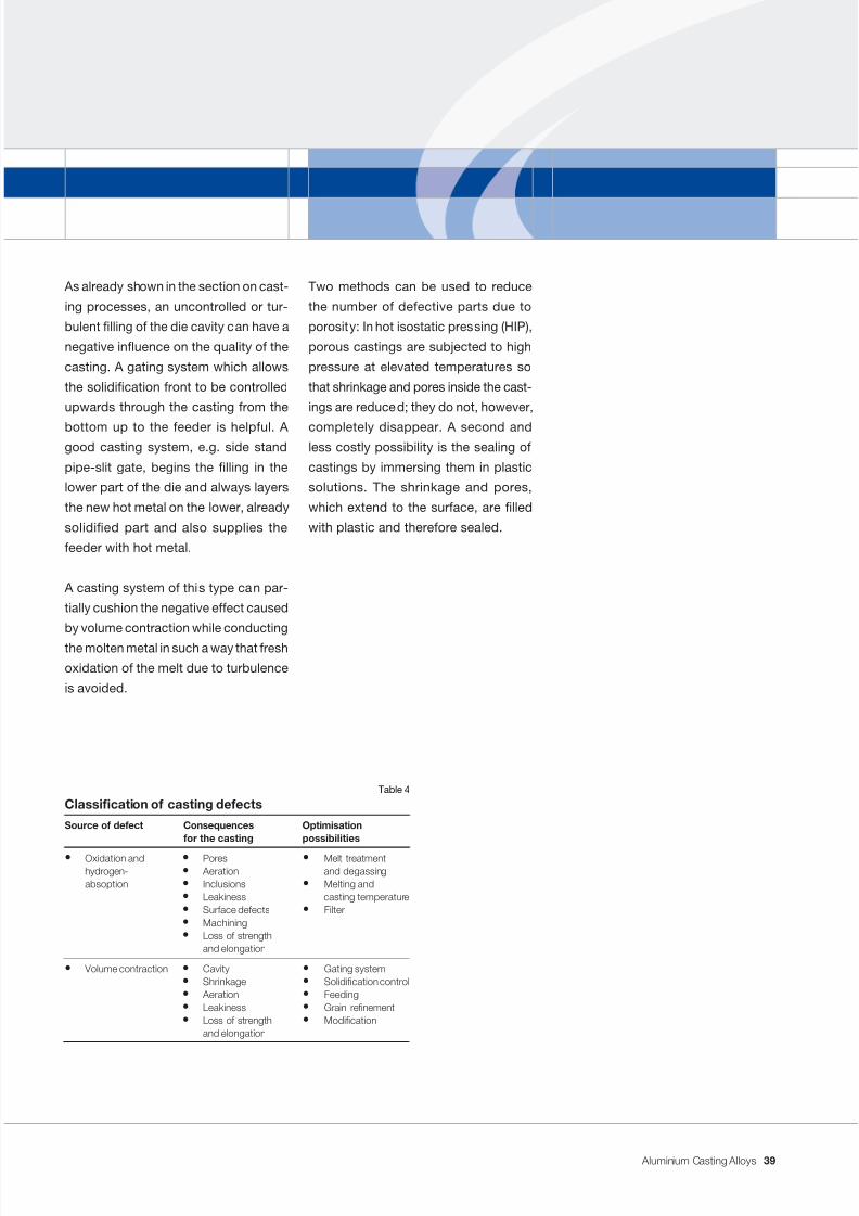
7/31/2019 Aluminium Casting Alloys EnglishVersion 2011
http://slidepdf.com/reader/full/aluminium-casting-alloys-englishversion-2011 39/102
Aluminium Casting Alloys
As already shown in the section on cast-
ing processes, an uncontrolled or tur-
bulent lling of the die cavity can have a
negative inuence on the quality of the
casting. A gating system which allows
the solidication front to be controlled
upwards through the casting from the
bottom up to the feeder is helpful. Agood casting system, e.g. side stand
pipe-slit gate, begins the lling in the
lower part of the die and always layers
the new hot metal on the lower, already
solidied part and also supplies the
feeder with hot metal.
A casting system of this type can par-
tially cushion the negative effect caused
by volume contraction while conducting
the molten metal in such a way that fresh
oxidation of the melt due to turbulence
is avoided.
Two methods can be used to reduce
the number of defective parts due to
porosity: In hot isostatic pressing (HIP),
porous castings are subjected to high
pressure at elevated temperatures so
that shrinkage and pores inside the cast-
ings are reduced; they do not, however,
completely disappear. A second andless costly possibility is the sealing of
castings by immersing them in plastic
solutions. The shrinkage and pores,
which extend to the surface, are lled
with plastic and therefore sealed.
Classication of casting defects
Source of defect Consequences Optimisationfor the casting possibilities
• Oxidation and • Pores • Melt treatmenthydrogen- • Aeration and degassing
absoption • Inclusions • Melting and• Leakiness casting temperature• Surface defects • Filter• Machining• Loss of strength
and elongation
• Volume contraction • Cavity • Gating system• Shrinkage • Solidication control• Aeration • Feeding• Leakiness • Grain renement• Loss of strength • Modication
and elongation
Table 4
39
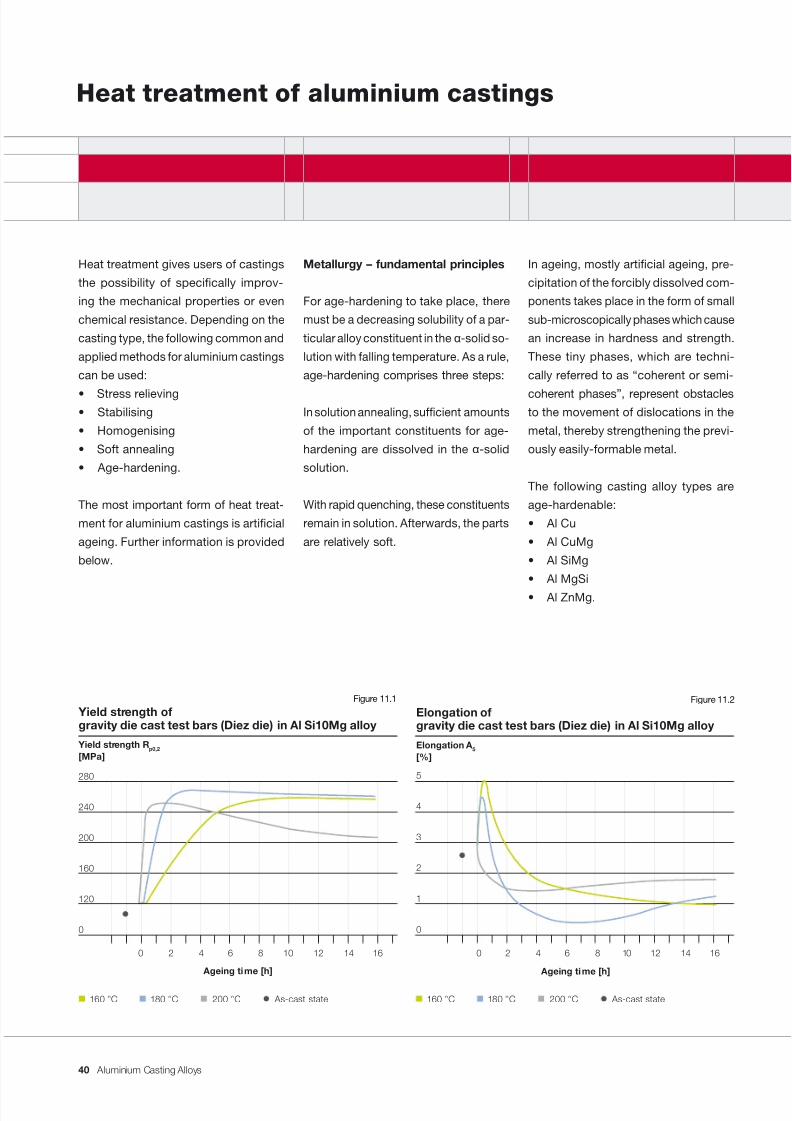
7/31/2019 Aluminium Casting Alloys EnglishVersion 2011
http://slidepdf.com/reader/full/aluminium-casting-alloys-englishversion-2011 40/102
Aluminium Casting Alloys
Heat treatment of aluminium castings
In ageing, mostly articial ageing, pre-
cipitation of the forcibly dissolved com-
ponents takes place in the form of small
sub-microscopically phases which cause
an increase in hardness and strength.
These tiny phases, which are techni-
cally referred to as “coherent or semi-
coherent phases”, represent obstaclesto the movement of dislocations in the
metal, thereby strengthening the previ-
ously easily-formable metal.
The following casting alloy types are
age-hardenable:
• Al Cu
• Al CuMg
• Al SiMg
• Al MgSi
• Al ZnMg.
Metallurgy – fundamental principles
For age-hardening to take place, there
must be a decreasing solubility of a par-
ticular alloy constituent in the α -solid so-
lution with falling temperature. As a rule,
age-hardening comprises three steps:
In solution annealing, sufcient amounts
of the important constituents for age-
hardening are dissolved in the α -solid
solution.
With rapid quenching, these constituents
remain in solution. Afterwards, the parts
are relatively soft.
Heat treatment gives users of castings
the possibility of specically improv-
ing the mechanical properties or even
chemical resistance. Depending on the
casting type, the following common and
applied methods for aluminium castings
can be used:
• Stress relieving• Stabilising
• Homogenising
• Soft annealing
• Age-hardening.
The most important form of heat treat-
ment for aluminium castings is articial
ageing. Further information is provided
below.
Ageing time [h]
Yield strength ofgravity die cast test bars (Diez die) in Al Si10Mg alloy
Yield strength R p0,2
[MPa]
280
240
200
160
120
0
0 2 4 6 8 10 12 14 16
As-cast state160 °C 180 °C 200 °C
Figure 11.1
Ageing time [h]
Elongation ofgravity die cast test bars (Diez die) in Al Si10Mg alloy
Elongation A 5
[%]
5
4
3
2
1
0
0 2 4 6 8 10 12 14 16
As-cast state160 °C 180 °C 200 °C
Figure 11.2
40
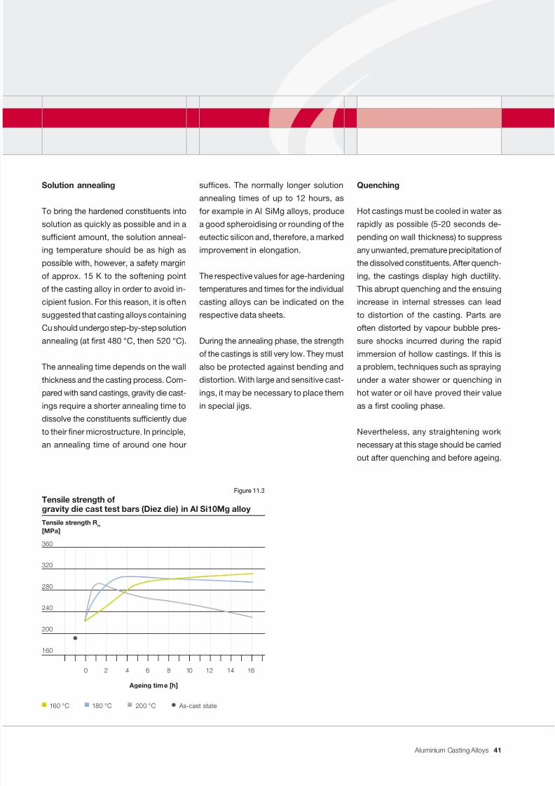
7/31/2019 Aluminium Casting Alloys EnglishVersion 2011
http://slidepdf.com/reader/full/aluminium-casting-alloys-englishversion-2011 41/102
Aluminium Casting Alloys
Ageing time [h]
Tensile strength ofgravity die cast test bars (Diez die) in Al Si10Mg alloy
Tensile strength R m [MPa]
360
320
280
240
200
160
0 2 4 6 8 10 12 14 16
As-cast state160 °C 180 °C 200 °C
Figure 11.3
Solution annealing
To bring the hardened constituents into
solution as quickly as possible and in a
sufcient amount, the solution anneal-
ing temperature should be as high as
possible with, however, a safety margin
of approx. 15 K to the softening pointof the casting alloy in order to avoid in-
cipient fusion. For this reason, it is often
suggested that casting alloys containing
Cu should undergo step-by-step solution
annealing (at rst 480 °C, then 520 °C).
The annealing time depends on the wall
thickness and the casting process. Com-
pared with sand castings, gravity die cast-
ings require a shorter annealing time to
dissolve the constituents sufciently due
to their ner microstructure. In principle,
an annealing time of around one hour
sufces. The normally longer solution
annealing times of up to 12 hours, as
for example in Al SiMg alloys, produce
a good spheroidising or rounding of the
eutectic silicon and, therefore, a marked
improvement in elongation.
The respective values for age-hardeningtemperatures and times for the individual
casting alloys can be indicated on the
respective data sheets.
During the annealing phase, the strength
of the castings is still very low. They must
also be protected against bending and
distortion. With large and sensitive cast-
ings, it may be necessary to place them
in special jigs.
Quenching
Hot castings must be cooled in water as
rapidly as possible (5-20 seconds de-
pending on wall thickness) to suppress
any unwanted, premature precipitation of
the dissolved constituents. After quench-
ing, the castings display high ductility.This abrupt quenching and the ensuing
increase in internal stresses can lead
to distortion of the casting. Parts are
often distorted by vapour bubble pres-
sure shocks incurred during the rapid
immersion of hollow castings. If this is
a problem, techniques such as spraying
under a water shower or quenching in
hot water or oil have proved their value
as a rst cooling phase.
Nevertheless, any straightening work
necessary at this stage should be carried
out after quenching and before ageing.
41
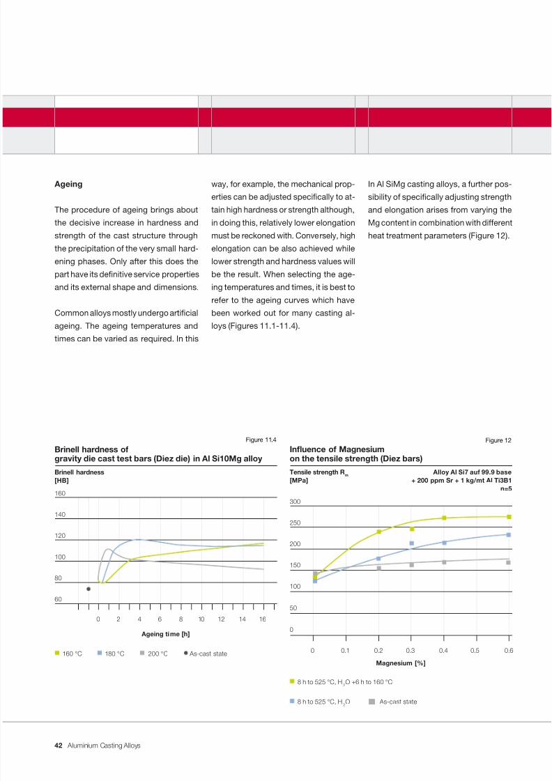
7/31/2019 Aluminium Casting Alloys EnglishVersion 2011
http://slidepdf.com/reader/full/aluminium-casting-alloys-englishversion-2011 42/102
Aluminium Casting Alloys
Ageing
The procedure of ageing brings about
the decisive increase in hardness and
strength of the cast structure through
the precipitation of the very small hard-
ening phases. Only after this does the
part have its denitive service propertiesand its external shape and dimensions.
Common alloys mostly undergo articial
ageing. The ageing temperatures and
times can be varied as required. In this
way, for example, the mechanical prop-
erties can be adjusted specically to at-
tain high hardness or strength although,
in doing this, relatively lower elongation
must be reckoned with. Conversely, high
elongation can be also achieved while
lower strength and hardness values will
be the result. When selecting the age-ing temperatures and times, it is best to
refer to the ageing curves which have
been worked out for many casting al-
loys (Figures 11.1-11.4).
In Al SiMg casting alloys, a further pos-
sibility of specically adjusting strength
and elongation arises from varying the
Mg content in combination with different
heat treatment parameters (Figure 12).
Ageing time [h]
Brinell hardness ofgravity die cast test bars (Diez die) in Al Si10Mg alloy
Brinell hardness[HB]
160
140
120
100
80
60
0 2 4 6 8 10 12 14 16
As-cast state160 °C 180 °C 200 °C
Figure 11.4
Magnesium [%]
Inuence of Magnesiumon the tensile strength (Diez bars)
Tensile strength R m Alloy Al Si7 auf 99.9 base[MPa] + 200 ppm Sr + 1 kg/mt Al Ti3B1
n=5
300
250
200
150
100
50
0
0 0.1 0.2 0.3 0.4 0.5 0.6
8 h to 525 °C, H 2O As-cast state
8 h to 525 °C, H 2O +6 h to 160 °C
Figure 12
42
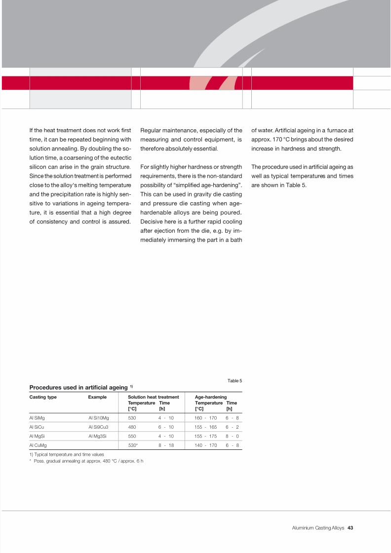
7/31/2019 Aluminium Casting Alloys EnglishVersion 2011
http://slidepdf.com/reader/full/aluminium-casting-alloys-englishversion-2011 43/102
Aluminium Casting Alloys
If the heat treatment does not work rst
time, it can be repeated beginning with
solution annealing. By doubling the so-
lution time, a coarsening of the eutectic
silicon can arise in the grain structure.
Since the solution treatment is performed
close to the alloy‘s melting temperature
and the precipitation rate is highly sen-sitive to variations in ageing tempera-
ture, it is essential that a high degree
of consistency and control is assured.
Regular maintenance, especially of the
measuring and control equipment, is
therefore absolutely essential.
For slightly higher hardness or strength
requirements, there is the non-standard
possibility of “simplied age-hardening”.
This can be used in gravity die castingand pressure die casting when age-
hardenable alloys are being poured.
Decisive here is a further rapid cooling
after ejection from the die, e.g. by im-
mediately immersing the part in a bath
of water. Articial ageing in a furnace at
approx. 170 °C brings about the desired
increase in hardness and strength.
The procedure used in articial ageing as
well as typical temperatures and times
are shown in Table 5.
Procedures used in articial ageing 1) Casting type Example Solution heat treatment Age-hardening
Temperature Time Temperature Time[°C] [h] [°C] [h]
Al SiMg Al Si10Mg 530 4 - 10 160 - 170 6 - 8
Al SiCu Al Si9Cu3 480 6 - 10 155 - 165 6 - 2
Al MgSi Al Mg3Si 550 4 - 10 155 - 175 8 - 0
Al CuMg 530* 8 - 18 140 - 170 6 - 8
1) Typical temperature and time values* Poss. gradual annealing at approx. 480 °C / approx. 6 h
Table 5
43
7/31/2019 Aluminium Casting Alloys EnglishVersion 2011
http://slidepdf.com/reader/full/aluminium-casting-alloys-englishversion-2011 44/102
Aluminium Casting Alloys
Mechanical machining of aluminium castings
High-speed steel and hard metal or
ceramic plates are used as cutting tool
materials; for micronishing, diamonds
are often utilised.
The following machining allowances are
given for the main casting processes:
• sand castings: 1.5-3 mm• gravity die castings: 0.7-1.5 mm
• pressure die castings: 0.3-0.5 mm.
In order to minimise value losses, turnings
and chips should be sorted out according
to casting alloy type and stored possi-
bly in briquettes. In addition, dampness,
grease and free iron reduce the value of
chips and turnings. Aluminium chips and
turnings are not hazardous materials and
there is no risk of re during storage.
When grinding aluminium parts, explosion-
proof separation of the dust is stipulated.
With softer materials and also with most
hypoeutectic AlSi casting alloys, narrow
tools, i.e. with a large rake angle, cause
the least possible surface roughness.
These casting alloys produce narrow-
spiral or short-breaking turnings. When
machining aluminium, suitable emul-
sions with water are used as coolingagents and lubricants. Friable and chips
and ne to powdery Si dust arise when
machining hypereutectic casting alloys.
In combination with the lubricant, this
powder produces an abradant which is
often processed when dry. In some re-
spects, the machining of these casting
alloy types is similar to grey cast iron.
With workpieces made from Al Si12
casting alloys with their very soft matrix,
a large volume of long curly spirals are
produced. In addition, the plastic mate-
rial tends to build up edges on the tool.
This leads to lubrication and, as a result,
a poor surface appearance. When this
occurs, it often gives the machinist the
subjective impression of bad machina-
bility although tool wear is not the cause
in this case.
In general, parts made from aluminium
casting alloys are easy-machinable.
This also applies for all metal-cutting
processes. Low cutting force allows a
high volume of metal to be removed. The
surface nish of the cast piece depends
on the machining conditions, such as
cutting speed, cutting geometry, lubri-cation and cooling.
The high cutting speeds required in alu-
minium to achieve minimum roughness
necessitate, with regard to processing
machines and tools, stable, vibration-
free construction and good cutting tools.
Besides the microstructure – including
defects, pores or inclusions – the silicon
content of the casting has a strong ef-
fect on tool wear. Modied, hypoeutectic
AlSi casting alloys have, e.g. the highest
tool time, while hypereutectic aluminium-
silicon piston casting alloys can cause
very considerable tool wear.
44
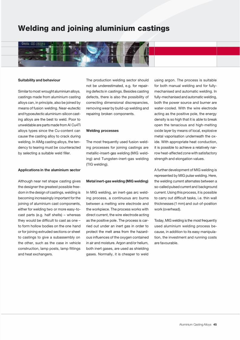
7/31/2019 Aluminium Casting Alloys EnglishVersion 2011
http://slidepdf.com/reader/full/aluminium-casting-alloys-englishversion-2011 45/102
Aluminium Casting Alloys
Welding and joining aluminium castings
using argon. The process is suitable
for both manual welding and for fully-
mechanised and automatic welding. In
fully-mechanised and automatic welding,
both the power source and burner are
water-cooled. With the wire electrode
acting as the positive pole, the energy
density is so high that it is able to breakopen the tenacious and high-melting
oxide layer by means of local, explosive
metal vaporisation underneath the ox-
ide. With appropriate heat conduction,
it is possible to achieve a relatively nar-
row heat-affected zone with satisfactory
strength and elongation values.
A further development of MIG welding is
represented by MIG pulse welding. Here,
the welding current alternates between a
so-called pulsed current and background
current. Using this process, it is possible
to carry out difcult tasks, i.e. thin wall
thicknesses (1 mm) and out-of-position
work (overhead).
Today, MIG welding is the most frequently
used aluminium welding process be-
cause, in addition to its easy manipula-
tion, the investment and running costsare favourable.
The production welding sector should
not be underestimated, e.g. for repair-
ing defects in castings. Besides casting
defects, there is also the possibility of
correcting dimensional discrepancies,
removing wear by build-up welding and
repairing broken components.
Welding processes
The most frequently used fusion weld-
ing processes for joining castings are
metallic-insert-gas welding (MIG weld-
ing) and Tungsten-inert-gas welding
(TIG welding).
Metal inert-gas welding (MIG welding)
In MIG welding, an inert-gas arc weld-
ing process, a continuous arc burns
between a melting wire electrode and
the workpiece. The process works with
direct current, the wire electrode acting
as the positive pole. The process is car-
ried out under an inert gas in order to
protect the melt area from the hazard-
ous inuences of the oxygen containedin air and moisture. Argon and/or helium,
both inert gases, are used as shielding
gases. Normally, it is cheaper to weld
Suitability and behaviour
Similar to most wrought aluminium alloys,
castings made from aluminium casting
alloys can, in principle, also be joined by
means of fusion welding. Near-eutectic
and hypoeutectic aluminium-silicon cast-
ing alloys are the best to weld. Poor tounweldable are parts made from Al Cu4Ti
alloys types since the Cu-content can
cause the casting alloy to crack during
welding. In AlMg casting alloys, the ten-
dency to tearing must be counteracted
by selecting a suitable weld ller.
Applications in the aluminium sector
Although near net shape casting gives
the designer the greatest possible free-
dom in the design of castings, welding is
becoming increasingly important for the
joining of aluminium cast components,
either for welding two or more easy-to-
cast parts (e.g. half shells) – whereas
they would be difcult to cast as one –
to form hollow bodies on the one hand
or for joining extruded sections or sheet
to castings to give a subassembly onthe other, such as the case in vehicle
construction, lamp posts, lamp ttings
and heat exchangers.
45
7/31/2019 Aluminium Casting Alloys EnglishVersion 2011
http://slidepdf.com/reader/full/aluminium-casting-alloys-englishversion-2011 46/102
Aluminium Casting Alloys
Tungsten-insert-gas welding
(TIG welding)
In TIG welding, an inert-gas shielded
arc welding process, an arc burns con-
tinuously between a non-consumable
electrode made of a tungsten alloy and
the casting. Alternating current is nor-mally used when welding aluminium. The
welding ller is fed in separately from
outside either by hand or mechanically.
The process is carried out under an in-
ert gas in order to protect the melt area
from the hazardous inuences of the
oxygen contained in air and moisture.
Argon and/or helium, both inert gases,
are used as shielding gases. Welding is
usually carried out with alternating cur-
rent and argon which is cheaper. This is
primarily a manual welding process but
there is a possibility to work with a full
degree of mechanisation. In TIG weld-
ing, the power source and the burner are
both water-cooled. By using alternating
current, the tenacious and high-melting
oxide layer is broken open during weld-
ing, similar to the MIG process. Weld-
ing normal diameter material with direct
current and a reverse-polarity tungstenelectrode would lead to destruction due
to electric overload. The electrode diam-
eter, however, can not be increased since
the current density required for welding
is no longer sufcient.
In one process variant, which has an
electrode with negative polarity as in the
welding of steel, welding is carried out
using direct current under a helium shield.
Compared with argon, helium displays
better thermal conductivity so that less
current is required to break open the ox-
ide layer. Consequently, the electrode isnot overloaded. In TIG welding, there are
also process variants which work with
the pulsed-current technique.
With regard to freedom from porosity,
the cleanest seams can be achieved
using TIG welding. One disadvantage
of the TIG welding process, however, is
the high local energy input. This leads
to considerable softening of the zone
adjacent to the weld which is also the
case with MIG welding. TIG welding, for
example, is an excellent process for the
repair of small casting defects. Com-
pared with the MIG process, however,
TIG welding operates at lower speeds.
Other thermal joining processes
The group of so-called “pressure welding
processes” also includes friction stear
welding (FSW) which is frequently used
for welding aluminium castings. Since this
welding process works without any ller
material, it is possible to join materialstogether which are not fusion-weldable
since they would form brittle inter-metallic
phases. By means of friction welding,
aluminium and steel, for example, can
be joined together.
The principle behind the process is to heat
the workpieces up to a pasty condition
followed by subjecting them to strong
compression. A weld upset is thus de-
veloped and, if necessary, subsequently
machined. The heating is done by rotat-
ing one or both parts and nally press-
ing them against each other until they
stop moving. It even allows workpieces
of circular and square cross-sections to
be joined together.
As a result of the rotary movement and
in order to keep the compression load
from increasing too much, a certain cross-sectional area may not be exceeded.
Another welding process is represented
by electron beam welding. Particular in-
terest is being shown in this process at
the moment for the welding of aluminium
pressure die castings.
46
7/31/2019 Aluminium Casting Alloys EnglishVersion 2011
http://slidepdf.com/reader/full/aluminium-casting-alloys-englishversion-2011 47/102
Aluminium Casting Alloys
The process operates mostly under high
vacuum. There are also process variants
which work under partial vacuum and
atmosphere although in these the advan-
tages of this welding process, namely the
production of narrower seams even with
thick workpieces, are extensively lost.
The welding of workpieces takes place
without ller material. The welding en-
ergy is imparted by means of a bundled
electron beam which is directed at the
welding point. The electron beams are
generated like those of a cathode ray
tube (television) in a high vacuum. Using
electron-optical focussing, different dis-
tances to the workpiece can be had with
this equipment, even when the workpiece
has undulating contours. Welding inside
closed containers is possible.
In addition to difcult-to-weld pressure
die castings, e.g. inlet manifolds, this
process has been successfully used with
cast semi-nished products in heat ex-
changers and in the welding of pistons
for internal combustion engines.
Weld preparation
To produce a sound weld, it is necessary
to observe certain “rules”. Weld prepa-
ration must match the welding process
being used and the wall thicknesses to
be joined. Excessive oxide formation is
worked off by metal-cutting. When grind-ing, resin-bonded grinding discs may
not be used (danger of pore formation).
Another possible way of removing ox-
ides is to etch the component. Grease
and dirt in the welding area have to be
removed using suitable means (danger
of pore formation). Components with
greater wall thicknesses to be joined
should be pre-heated before welding.
Weld ller materials
Weld ller materials are standardised.
The selection of weld ller materials is
guided by the materials of the parts to
be joined. For the most commonly used
aluminium materials, such as near- and
hypoeutectic AlSi casting alloys as
well as age-hardenable Al Si10Mg and Al Si5Mg variants, S-Al Si12 and S-Al Si5
weld ller materials are recommended.
A great danger in welding is the tendency
of many materials to form cracks during
the transition from liquid to solid state.
The cause of these cracks is weld shrink-
age stresses which occur during cooling.
Often the low melting point phases of
the weld ller materials are insufcient
to “heal” the cracks arising. Through theselection of a softer weld ller material
with a larger share of low melting point
phases, this danger is reduced. In do-
ing this, however, the optimum strength
properties in the weld seam must be
frequently foregone.
The decorative anodisation of a welded
joint with the aforementioned ller ma-
terials is not possible because the weld
seam would appear dark. Technical an-
odic oxidation for protective and adhesive
purposes is, however, always possible.
47
7/31/2019 Aluminium Casting Alloys EnglishVersion 2011
http://slidepdf.com/reader/full/aluminium-casting-alloys-englishversion-2011 48/102
Aluminium Casting Alloys
Surface treatment: corrosionand corrosion protection
remove the oxide lm completely and,
as a rule, act as a preparation to further
surface treatment. Possible sources of
defects leading to subsequent faults
comprise the use of brushes made of
brass or non-stainless steel as well as
sand or steel shot.
When grinding, the use of ceramic
grinding elements without further pre-
treatment frequently leads to good paint
adhesion. One precondition is that no
nes from the grinding elements are
pressed into the surface of the cast-
ing. Chemical degreasing agents with
a pickling or etching effect remove the
oxide layer and, as a consequence, all
impurities. It is also worth mentioning
that there is also matt or bright pickling
before anodic oxidation to produce a
special surface nish.
Following the alkaline pickling of AlMg
or AlSi casting alloys, the pickling lm
must be removed by means of an acid
after-treatment with nitric acid, nitric/
hydrouoric acid or sulphuric/hydro-
uoric acid. Instead of alkaline pickling
with nal dipping, it is more benecialto use an acidic uoride-containing
pickling solution immediately.
slightly alkaline media (e.g. ammonia
solutions) since magnesium oxide in
contrast to aluminium oxide is insoluble
in alkaline solutions.
Copper as an alloying element causes
a deterioration in corrosion properties.
This increases slightly with a rising Cu-content in the range below 0.2 % cop-
per, above 0.2 to 0.4 % more strongly.
Already with a Cu-content of 0.2 %,
permanent action from aqueous solu-
tions containing chlorine can have a very
negative effect on corrosion behaviour.
The negative inuence of iron on cor-
rosion behaviour is not as distinctive
as that of copper. With an Fe-content
of up to 0.6 %, there is no signicant
deterioration in the corrosion behaviour
of casting alloys.
The surface treatment of aluminium cast
products is carried out to improve their
corrosion resistance, for decorative
purposes or to increase the strength
of the components.
A homogeneous, non-porous cast struc-
ture free from shrink holes and cracksmakes coating easier. The quality of the
coating is inuenced decisively by the
pre-treatment.
Wiping, immersion and steam degreas-
ing (in that order) produce increasingly
grease-free surfaces without removing
the surface oxide lm. Grinding, brush-
ing, abrasive blasting or polishing do not
Aluminium casting alloys – like wrought
aluminium alloys – owe their corrosion
resistance to a thin, tenacious coating
layer of oxides and hydroxides. In the pH
range from 4.5 to 8.5, this oxide layer is
practically insoluble in aqueous media
and aluminium casting materials suffer
only negligible mass disappearance.
This passivity can, however, be annulled
locally at weak points in the oxide layer
due to the action of water containing
chloride. Since the aqueous medium,
e.g. weather, only acts periodically, a
protective oxide layer forms again at
small, local corrosion sites, e.g. repas-
sivation occurs. Deep pitting corrosion
can only arise when there is a long-term
effect from aggressive water contain-
ing chloride (e.g. sea water). Beside the
chloride content, the amount of oxygen
in the water also plays a role; cor rosion
reaction can only occur in neutral me-
dia (pH = 4.5-8.5) in the presence of
oxygen. The remedy for this can come
in the form of passive protection by
coating or by means of active cathodic
corrosion protection using a sacricial
anode, for example.
Magnesium as an alloying element
causes the formation of a thicker oxide
layer containing MgO and, consequently,
provides greater corrosion protection
against water containing chlorides and
48
7/31/2019 Aluminium Casting Alloys EnglishVersion 2011
http://slidepdf.com/reader/full/aluminium-casting-alloys-englishversion-2011 49/102
Aluminium Casting Alloys
Of the unlimited number of application
techniques used for volume lacquering,
electrostatic powder coating, whirl sin-
tering and electrophoretic dip coating
are to be stressed in particular because
of their environmental soundness, in
addition to the dip coating and spray-
ing (air, airless and electrostatic) of wetpaint containing solvents.
With the aid of anodic oxidation, the
nish achieved using mechanical or
chemical surface treatment can be con-
served permanently. These anodically
produced oxide layers are connected
solidly to the aluminium and, in contrast
to lacquering, the surface structure of
the original metal is unchanged. This
can prove disadvantageous, especial-
ly in pressure die casting. In today‘s
widely-used sulphuric acid anodising
process, the anodically-formed oxide
layers become resistant to touch (e.g.
nger marking) and abrasion resistant
after sealing in hot water and possess
good electric strength. The appearance
of anodically-oxidised aluminium cast-
ings is considerably inuenced by the
alloy composition and the microstruc-tural condition. For decorative purposes,
Al Mg3H, Al Mg3, Al Mg3Si, Al Mg5,
Al Mg5Si and Al 99.5 and/or Al 99.7
casting alloys have proved their worth.
A decorative anodic oxidation of alloys
with an Si-content > 1 % is not possi-
ble (with the exception of Al Si2MgTi).
Despite careful acid cleaning, a lac-
quered aluminium surface can still dis-
play adhesive failure after a certain time
due to environmental effects. Firstly,
a conversion layer, which forms as a
result of the reaction between chemi-
cals containing chrome and the metal,
passivates the aluminium surface andprotects it from the water diffused by
each layer of lacquer. With respect to
the promotion of adhesion and corro-
sion inhibition, the almost equivalent
green and yellow chromate coatings
have proved their worth over many
years. A clear chromate coating, pref-
erably used under clear lacquer, offers
slightly less corrosion protection due
to the layer being thinner. Cr-VI-free
chromate-phosphate coatings meet the
requirements of food processing and
distribution laws and are permitted for
the pre-treatment of aluminium which
is used in food production, processing
and packaging.
A chrome-free epoxy primer should
be mentioned as a possible but also
qualitatively less favourable alternative.
A precondition for the effectiveness ofthis alternate process, however, is also
the removal of the aluminium oxide layer
by chemical or mechanical means.
The possibility of producing coloured
oxide layers also exists by means of dip
painting, electrolytic colouring and in-
tegral colouring in special electrolytes
(integral process).
For surfaces which have to meet particular
requirements with regard to hardness,resistance to abrasion and wear, slid-
ing capacity and electric strength, the
special possibility of using hard anodis-
ing should be taken into consideration.
49
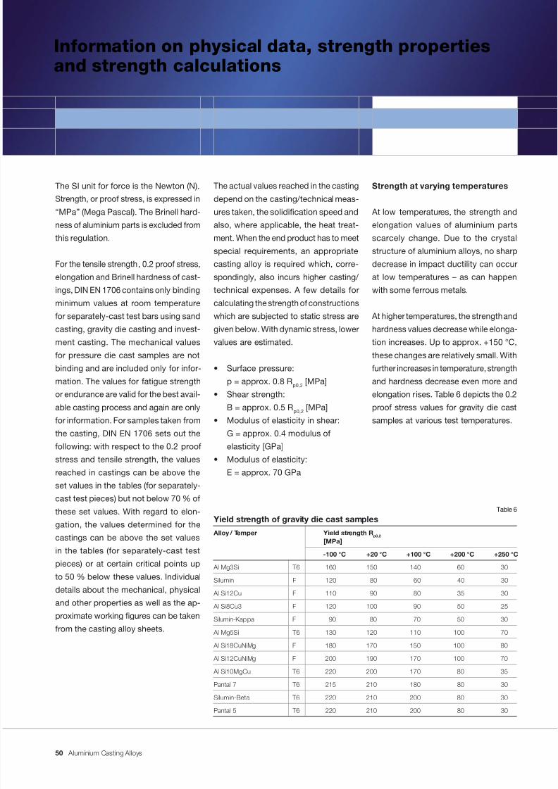
7/31/2019 Aluminium Casting Alloys EnglishVersion 2011
http://slidepdf.com/reader/full/aluminium-casting-alloys-englishversion-2011 50/102
Aluminium Casting Alloys
Information on physical data, strength propertiesand strength calculations
Strength at varying temperatures
At low temperatures, the strength and
elongation values of aluminium parts
scarcely change. Due to the crystal
structure of aluminium alloys, no sharp
decrease in impact ductility can occur
at low temperatures – as can happenwith some ferrous metals.
At higher temperatures, the strength and
hardness values decrease while elonga-
tion increases. Up to approx. +150 °C,
these changes are relatively small. With
further increases in temperature, strength
and hardness decrease even more and
elongation rises. Table 6 depicts the 0.2
proof stress values for gravity die cast
samples at various test temperatures.
The actual values reached in the casting
depend on the casting/technical meas-
ures taken, the solidication speed and
also, where applicable, the heat treat-
ment. When the end product has to meet
special requirements, an appropriate
casting alloy is required which, corre-
spondingly, also incurs higher casting/ technical expenses. A few details for
calculating the strength of constructions
which are subjected to static stress are
given below. With dynamic stress, lower
values are estimated.
• Surface pressure:
p = approx. 0.8 R p0,2 [MPa]
• Shear strength:
B = approx. 0.5 R p0,2 [MPa]
• Modulus of elasticity in shear:
G = approx. 0.4 modulus of
elasticity [GPa]
• Modulus of elasticity:
E = approx. 70 GPa
The SI unit for force is the Newton (N).
Strength, or proof stress, is expressed in
“MPa” (Mega Pascal). The Brinell hard-
ness of aluminium parts is excluded from
this regulation.
For the tensile strength, 0.2 proof stress,
elongation and Brinell hardness of cast-ings, DIN EN 1706 contains only binding
minimum values at room temperature
for separately-cast test bars using sand
casting, gravity die casting and invest-
ment casting. The mechanical values
for pressure die cast samples are not
binding and are included only for infor-
mation. The values for fatigue strength
or endurance are valid for the best avail-
able casting process and again are only
for information. For samples taken from
the casting, DIN EN 1706 sets out the
following: with respect to the 0.2 proof
stress and tensile strength, the values
reached in castings can be above the
set values in the tables (for separately-
cast test pieces) but not below 70 % of
these set values. With regard to elon-
gation, the values determined for the
castings can be above the set values
in the tables (for separately-cast testpieces) or at certain critical points up
to 50 % below these values. Individual
details about the mechanical, physical
and other properties as well as the ap-
proximate working gures can be taken
from the casting alloy sheets.
Yield strength of gravity die cast samples
Alloy / Temper Yield strength R p0,2 [MPa]
-100 °C +20 °C +100 °C +200 °C +250 °C
Al Mg3Si T6 160 150 140 60 30
Silumin F 120 80 60 40 30
Al Si12Cu F 110 90 80 35 30
Al Si8Cu3 F 120 100 90 50 25
Silumin-Kappa F 90 80 70 50 30
Al Mg5Si T6 130 120 110 100 70
Al Si18CuNiMg F 180 170 150 100 80
Al Si12CuNiMg F 200 190 170 100 70
Al Si10MgCu T6 220 200 170 80 35
Pantal 7 T6 215 210 180 80 30
Silumin-Beta T6 220 210 200 80 30
Pantal 5 T6 220 210 200 80 30
Table 6
50

7/31/2019 Aluminium Casting Alloys EnglishVersion 2011
http://slidepdf.com/reader/full/aluminium-casting-alloys-englishversion-2011 51/102
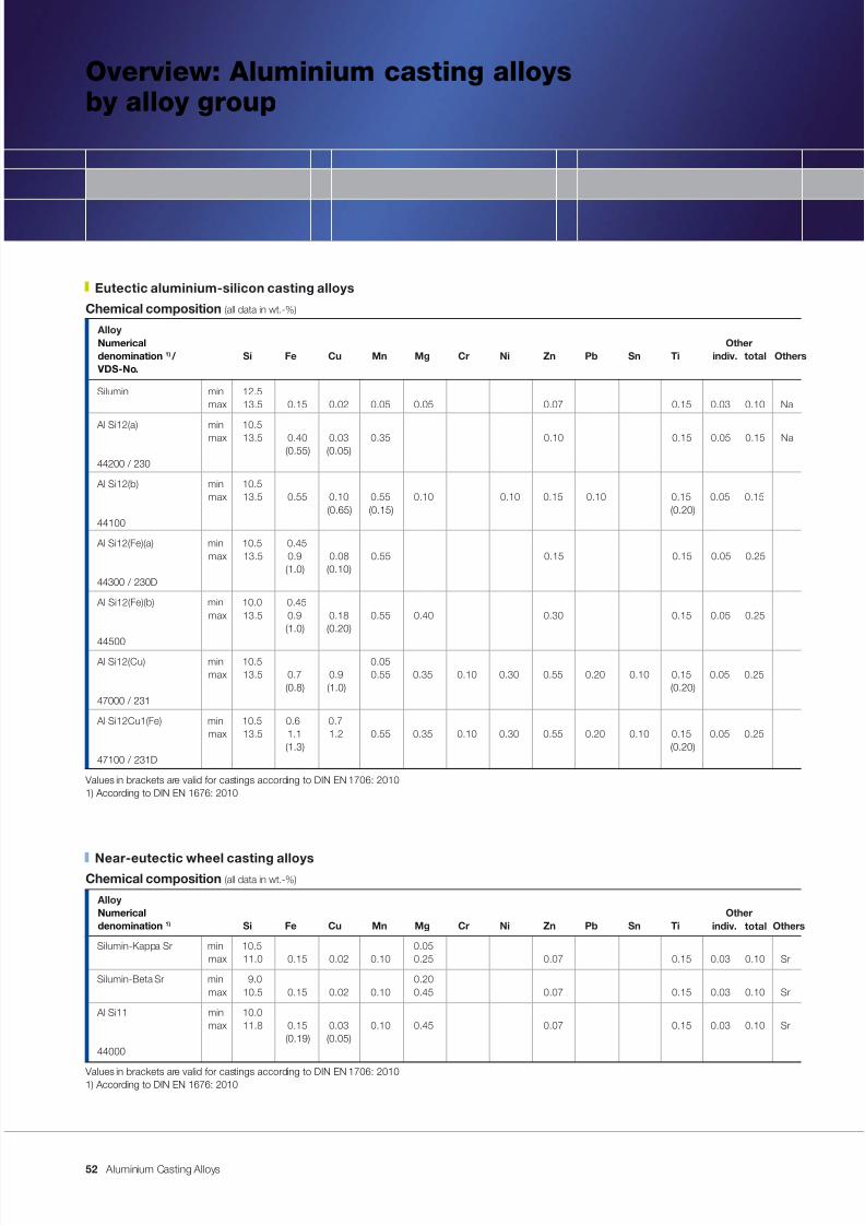
7/31/2019 Aluminium Casting Alloys EnglishVersion 2011
http://slidepdf.com/reader/full/aluminium-casting-alloys-englishversion-2011 52/102
Aluminium Casting Alloys
Overview: Aluminium casting alloysby alloy group
Chemical composition (all data in wt.-%)
AlloyNumerical Other
denomination 1) / Si Fe Cu Mn Mg Cr Ni Zn Pb Sn Ti VDS-No.
Silumin min 12.5max 13.5 0.15 0.02 0.05 0.05 0.07 0.15 0.03 0.10 Na
Al Si12(a) min 10.5max 13.5 0.40 0.03 0.35 0.10 0.15 0.05 0.15 Na (0.55) (0.05)
44200 / 230
Al Si12(b) min 10.5max 13.5 0.55 0.10 0.55 0.10 0.10 0.15 0.10 0.15 0.05 0.15
(0.65) (0.15) (0.20)44100
Al Si12(Fe)(a) min 10.5 0.45 max 13.5 0.9 0.08 0.55 0.15 0.15 0.05 0.25
(1.0) (0.10)44300 / 230D
Al Si12(Fe)(b) min 10.0 0.45max 13.5 0.9 0.18 0.55 0.40 0.30 0.15 0.05 0.25
(1.0) (0.20)
44500Al Si12(Cu) min 10.5 0.05
max 13.5 0.7 0.9 0.55 0.35 0.10 0.30 0.55 0.20 0.10 0.15 0.05 0.25(0.8) (1.0) (0.20)
47000 / 231
Al Si12Cu1(Fe) min 10.5 0.6 0.7max 13.5 1.1 1.2 0.55 0.35 0.10 0.30 0.55 0.20 0.10 0.15 0.05 0.25
(1.3) (0.20)47100 / 231D
Values in brackets are valid for castings according to DIN EN 1706: 20101) According to DIN EN 1676: 2010
Otherstotalindiv.
Eutectic aluminium-silicon casting alloys
Near-eutectic wheel casting alloysChemical composition (all data in wt.-%)
AlloyNumerical Other
denomination 1) Si Fe Cu Mn Mg Cr Ni Zn Pb Sn Ti
Silumin-Kappa Sr min 10.5 0.05max 11.0 0.15 0.02 0.10 0.25 0.07 0.15 0.03 0.10 Sr
Silumin-Beta Sr min 9.0 0.20max 10.5 0.15 0.02 0.10 0.45 0.07 0.15 0.03 0.10 Sr
Al Si11 min 10.0max 11.8 0.15 0.03 0.10 0.45 0.07 0.15 0.03 0.10 Sr
(0.19) (0.05)44000
Values in brackets are valid for castings according to DIN EN 1706: 20101) According to DIN EN 1676: 2010
Otherstotalindiv.
52
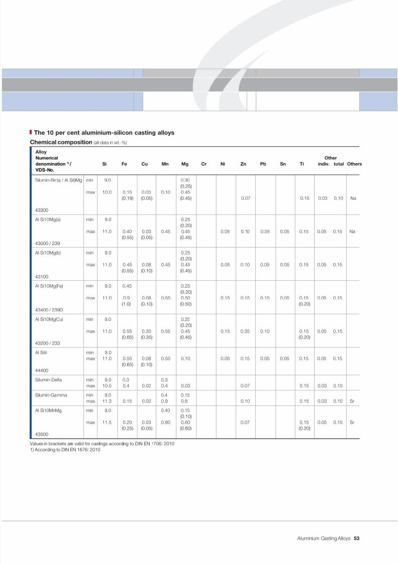
7/31/2019 Aluminium Casting Alloys EnglishVersion 2011
http://slidepdf.com/reader/full/aluminium-casting-alloys-englishversion-2011 53/102
Aluminium Casting Alloys
Chemical composition (all data in wt.-%)
AlloyNumerical Other
denomination 1) / Si Fe Cu Mn Mg Cr Ni Zn Pb Sn Ti VDS-No.
Silumin-Beta / Al Si9Mg min 9.0 0.30 (0.25)
max 10.0 0.15 0.03 0.10 0.45
(0.19) (0.05) (0.45) 0.07 0.15 0.03 0.10 Na
43300
Al Si10Mg(a) min 9.0 0.25 (0.20)
max 11.0 0.40 0.03 0.45 0.45 0.05 0.10 0.05 0.05 0.15 0.05 0.15 Na (0.55) (0.05) (0.45)
43000 / 239
Al Si10Mg(b) min 9.0 0.25 (0.20)
max 11.0 0.45 0.08 0.45 0.45 0.05 0.10 0.05 0.05 0.15 0.05 0.15 (0.55) (0.10) (0.45)
43100
Al Si10Mg(Fe) min 9.0 0.45 0.25 (0.20)
max 11.0 0.9 0.08 0.55 0.50 0.15 0.15 0.15 0.05 0.15 0.05 0.15(1.0) (0.10) (0.50) (0.20)
43400 / 239D
Al Si10Mg(Cu) min 9.0 0.25 (0.20)
max 11.0 0.55 0.30 0.55 0.45 0.15 0.35 0.10 0.15 0.05 0.15(0.65) (0.35) (0.45) (0.20)
43200 / 233
Al Si9 min 8.0max 11.0 0.55 0.08 0.50 0.10 0.05 0.15 0.05 0.05 0.15 0.05 0.15
(0.65) (0.10)44400
Silumin-Delta min 9.0 0.3 0.3max 10.5 0.4 0.02 0.4 0.03 0.07 0.15 0.03 0.10
Silumin-Gamma min 9.0 0.4 0.15max 11.3 0.15 0.02 0.9 0.6 0.10 0.15 0.03 0.10 Sr
Al Si10MnMg min 9.0 0.40 0.15 (0.10)
max 11.5 0.20 0.03 0.80 0.60 0.07 0.15 0.05 0.15 Sr (0.25) (0.05) (0.60) (0.20)
43500
Values in brackets are valid for castings according to DIN EN 1706: 20101) According to DIN EN 1676: 2010
Otherstotalindiv.
The 10 per cent aluminium-silicon casting alloys
53
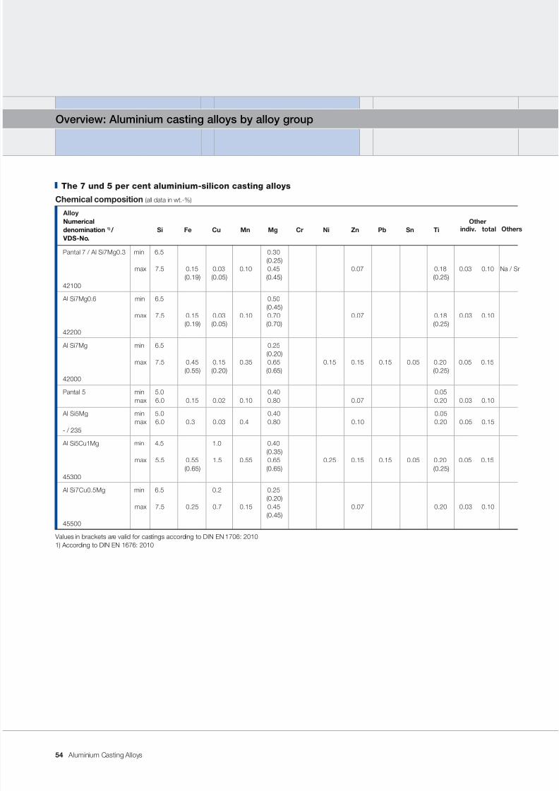
7/31/2019 Aluminium Casting Alloys EnglishVersion 2011
http://slidepdf.com/reader/full/aluminium-casting-alloys-englishversion-2011 54/102
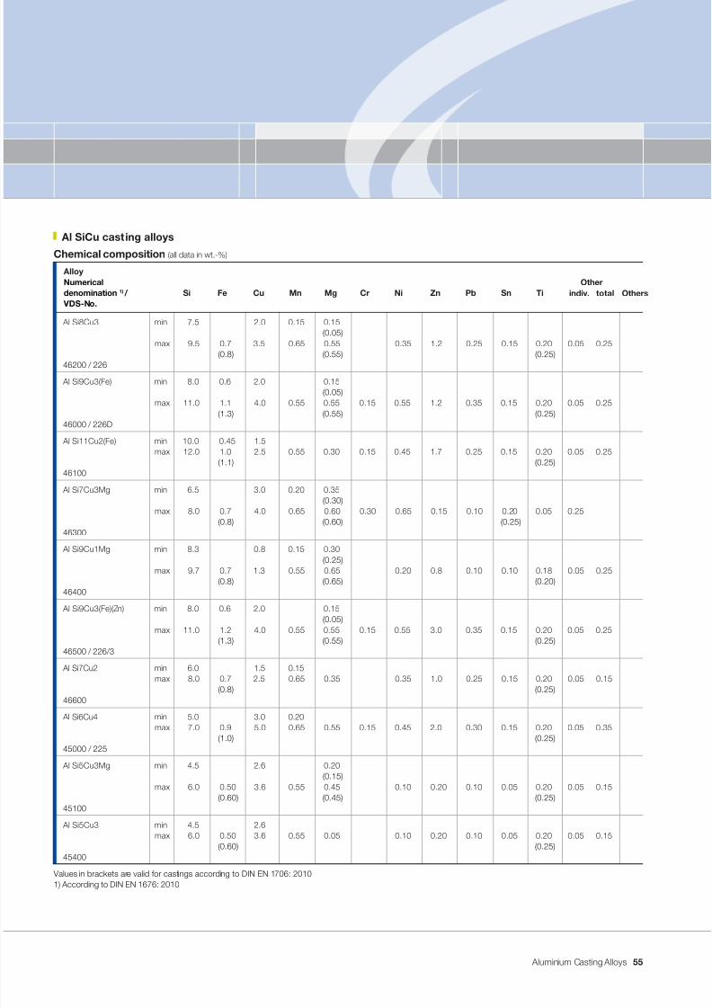
7/31/2019 Aluminium Casting Alloys EnglishVersion 2011
http://slidepdf.com/reader/full/aluminium-casting-alloys-englishversion-2011 55/102
Aluminium Casting Alloys
Chemical composition (all data in wt.-%)
AlloyNumerical Other
denomination 1) / Si Fe Cu Mn Mg Cr Ni Zn Pb Sn Ti VDS-No.
Al Si8Cu3 min 7.5 2.0 0.15 0.15 (0.05)
max 9.5 0.7 3.5 0.65 0.55 0.35 1.2 0.25 0.15 0.20 0.05 0.25
(0.8) (0.55) (0.25)46200 / 226
Al Si9Cu3(Fe) min 8.0 0.6 2.0 0.15 (0.05)
max 11.0 1.1 4.0 0.55 0.55 0.15 0.55 1.2 0.35 0.15 0.20 0.05 0.25(1.3) (0.55) (0.25)
46000 / 226D
Al Si11Cu2(Fe) min 10.0 0.45 1.5max 12.0 1.0 2.5 0.55 0.30 0.15 0.45 1.7 0.25 0.15 0.20 0.05 0.25
(1.1) (0.25)46100
Al Si7Cu3Mg min 6.5 3.0 0.20 0.35 (0.30)
max 8.0 0.7 4.0 0.65 0.60 0.30 0.65 0.15 0.10 0.20 0.05 0.25(0.8) (0.60) (0.25)
46300
Al Si9Cu1Mg min 8.3 0.8 0.15 0.30 (0.25)
max 9.7 0.7 1.3 0.55 0.65 0.20 0.8 0.10 0.10 0.18 0.05 0.25 (0.8) (0.65) (0.20)
46400
Al Si9Cu3(Fe)(Zn) min 8.0 0.6 2.0 0.15 (0.05)
max 11.0 1.2 4.0 0.55 0.55 0.15 0.55 3.0 0.35 0.15 0.20 0.05 0.25 (1.3) (0.55) (0.25)
46500 / 226/3
Al Si7Cu2 min 6.0 1.5 0.15max 8.0 0.7 2.5 0.65 0.35 0.35 1.0 0.25 0.15 0.20 0.05 0.15
(0.8) (0.25)46600
Al Si6Cu4 min 5.0 3.0 0.20max 7.0 0.9 5.0 0.65 0.55 0.15 0.45 2.0 0.30 0.15 0.20 0.05 0.35
(1.0) (0.25)45000 / 225
Al Si5Cu3Mg min 4.5 2.6 0.20 (0.15)
max 6.0 0.50 3.6 0.55 0.45 0.10 0.20 0.10 0.05 0.20 0.05 0.15(0.60) (0.45) (0.25)
45100
Al Si5Cu3 min 4.5 2.6max 6.0 0.50 3.6 0.55 0.05 0.10 0.20 0.10 0.05 0.20 0.05 0.15
(0.60) (0.25)45400
Values in brackets are valid for castings according to DIN EN 1706: 2010
1) According to DIN EN 1676: 2010
Otherstotalindiv.
Al SiCu cast ing alloys
55
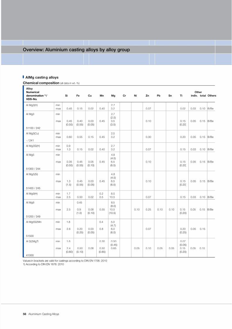
7/31/2019 Aluminium Casting Alloys EnglishVersion 2011
http://slidepdf.com/reader/full/aluminium-casting-alloys-englishversion-2011 56/102
Aluminium Casting Alloys
Overview: Aluminium casting alloys by alloy group
AlMg casting alloys
Chemical composition (all data in wt.-%)
AlloyNumerical Other
denomination 1) / Si Fe Cu Mn Mg Cr Ni Zn Pb Sn Ti VDS-No.
Al Mg3(H) min 2.7max 0.45 0.15 0.02 0.40 3.2 0.07 0.02 0.03 0.10 B/Be
Al Mg3 min 2.7 (2.5)max 0.45 0.40 0.03 0.45 3.5 0.10 0.15 0.05 0.15 B/Be
(0.55) (0.55) (0.05) (3.5) (0.20)51100 / 242
Al Mg3(Cu) min 2.5max 0.60 0.55 0.15 0.45 3.2 0.30 0.20 0.05 0.15 B/Be
- / 241
Al Mg3Si(H) min 0.9 2.7max 1.3 0.15 0.02 0.40 3.2 0.07 0.15 0.03 0.10 B/Be
Al Mg5 min 4.8 (4.5)
max 0.35 0.45 0.05 0.45 6.5 0.10 0.15 0.05 0.15 B/Be (0.55) (0.55) (0.10) (6.5) (0.20)
51300 / 244
Al Mg5(Si) min 4.8 (4.5)
max 1.3 0.45 0.03 0.45 6.5 0.10 0.15 0.05 0.15 B/Be (1.5) (0.55) (0.05) (6.5) (0.20)
51400 / 245
Al Mg9(H) min 1.7 0.2 8.5max 2.5 0.50 0.02 0.5 10.5 0.07 0.15 0.03 0.10 B/Be
Al Mg9 min 0.45 8.5 (8.0)
max 2.5 0.9 0.08 0.55 10.5 0.10 0.25 0.10 0.10 0.15 0.05 0.15 B/Be(1.0) (0.10) (10.5) (0.20)
51200 / 349
Al Mg5Si2Mn min 1.8 0.4 5.0 (4.7)
max 2.6 0.20 0.03 0.8 6.0 0.07 0.20 0.05 0.15(0.25) (0.05) (6.0) (0.25)
51500
Al Si2MgTi min 1.6 0.30 0.50 0.07(0.45) (0.05)
max 2.4 0.50 0.08 0.50 0.65 0.05 0.10 0.05 0.05 0.15 0.05 0.15(0.60) (0.10) (0.65) (0.20)
41000
Values in brackets are valid for castings according to DIN EN 1706: 20101) According to DIN EN 1676: 2010
Otherstotalindiv.
56
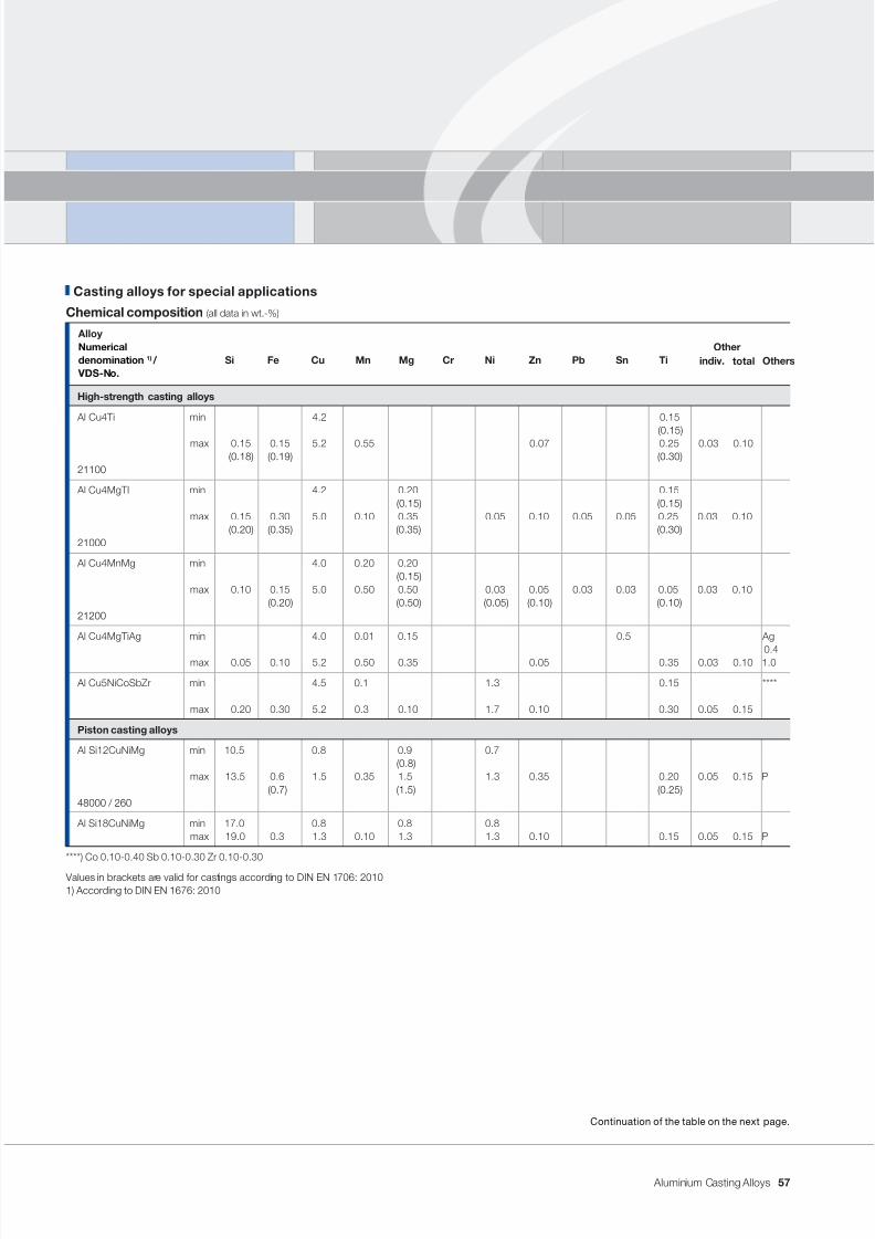
7/31/2019 Aluminium Casting Alloys EnglishVersion 2011
http://slidepdf.com/reader/full/aluminium-casting-alloys-englishversion-2011 57/102
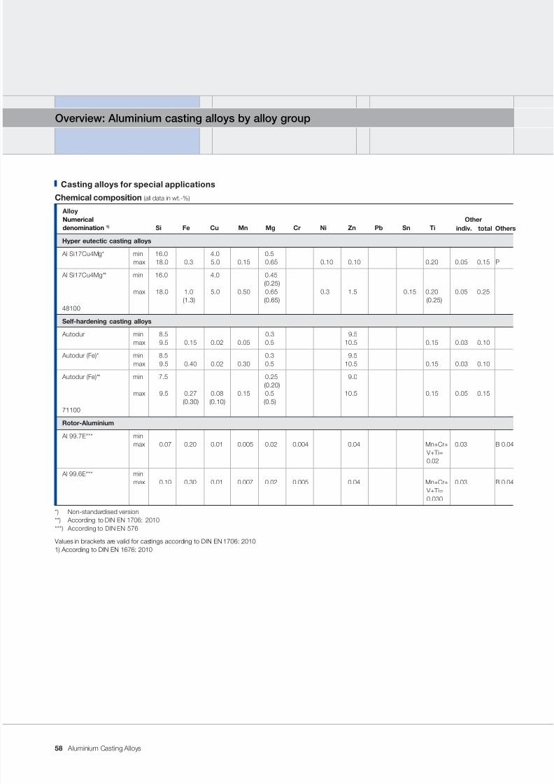
7/31/2019 Aluminium Casting Alloys EnglishVersion 2011
http://slidepdf.com/reader/full/aluminium-casting-alloys-englishversion-2011 58/102
Aluminium Casting Alloys
Overview: Aluminium casting alloys by alloy group
Casting alloys for special applications
Chemical composition (all data in wt.-%)
AlloyNumerical Other
denomination 1) Si Fe Cu Mn Mg Cr Ni Zn Pb Sn Ti
Hyper eutectic casting alloys
Al Si17Cu4Mg* min 16.0 4.0 0.5max 18.0 0.3 5.0 0.15 0.65 0.10 0.10 0.20 0.05 0.15 P
Al Si17Cu4Mg** min 16.0 4.0 0.45 (0.25)
max 18.0 1.0 5.0 0.50 0.65 0.3 1.5 0.15 0.20 0.05 0.25 (1.3) (0.65) (0.25)
48100
Self-hardening casting alloys
Autodur min 8.5 0.3 9.5max 9.5 0.15 0.02 0.05 0.5 10.5 0.15 0.03 0.10
Autodur (Fe)* min 8.5 0.3 9.5max 9.5 0.40 0.02 0.30 0.5 10.5 0.15 0.03 0.10
Autodur (Fe)** min 7.5 0.25 9.0 (0.20)
max 9.5 0.27 0.08 0.15 0.5 10.5 0.15 0.05 0.15 (0.30) (0.10) (0.5)
71100Rotor-Aluminium
Al 99.7E*** minmax 0.07 0.20 0.01 0.005 0.02 0.004 0.04 Mn+Cr+ 0.03 B 0.04
V+ Ti=0.02
Al 99.6E*** minmax 0.10 0.30 0.01 0.007 0.02 0.005 0.04 Mn+Cr+ 0.03 B 0.04
V+Ti=0.030
*) Non-standardised version**) According to DIN EN 1706: 2010***) According to DIN EN 576
Values in brackets are valid for castings according to DIN EN 1706: 2010
1) According to DIN EN 1676: 2010
Otherstotalindiv.
58
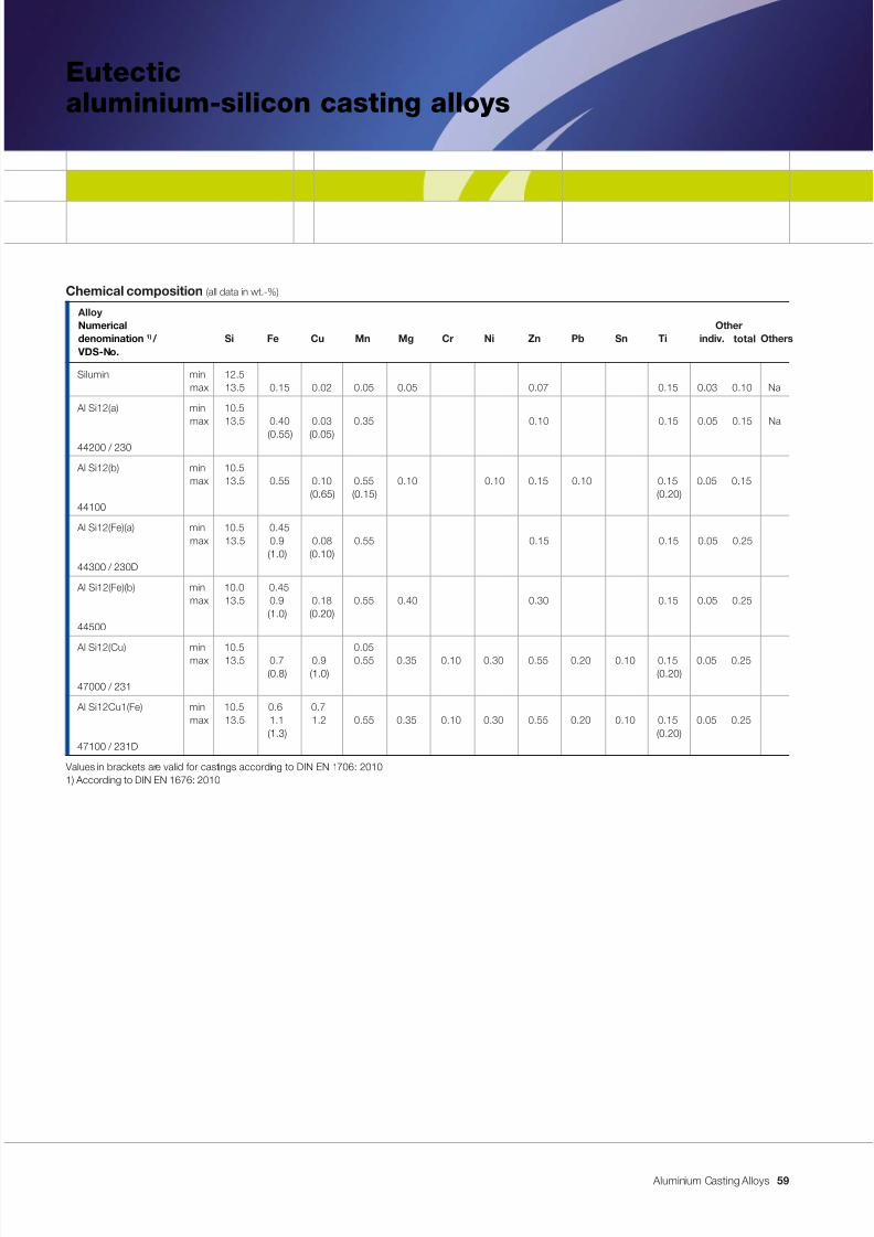
7/31/2019 Aluminium Casting Alloys EnglishVersion 2011
http://slidepdf.com/reader/full/aluminium-casting-alloys-englishversion-2011 59/102
Aluminium Casting Alloys
Eutecticaluminium-silicon casting alloys
Chemical composition (all data in wt.-%)
AlloyNumerical Other
denomination 1) / Si Fe Cu Mn Mg Cr Ni Zn Pb Sn Ti VDS-No.
Silumin min 12.5max 13.5 0.15 0.02 0.05 0.05 0.07 0.15 0.03 0.10 Na
Al Si12(a) min 10.5max 13.5 0.40 0.03 0.35 0.10 0.15 0.05 0.15 Na
(0.55) (0.05)44200 / 230
Al Si12(b) min 10.5max 13.5 0.55 0.10 0.55 0.10 0.10 0.15 0.10 0.15 0.05 0.15
(0.65) (0.15) (0.20)44100
Al Si12(Fe)(a) min 10.5 0.45 max 13.5 0.9 0.08 0.55 0.15 0.15 0.05 0.25
(1.0) (0.10)44300 / 230D
Al Si12(Fe)(b) min 10.0 0.45max 13.5 0.9 0.18 0.55 0.40 0.30 0.15 0.05 0.25
(1.0) (0.20)44500
Al Si12(Cu) min 10.5 0.05max 13.5 0.7 0.9 0.55 0.35 0.10 0.30 0.55 0.20 0.10 0.15 0.05 0.25(0.8) (1.0) (0.20)
47000 / 231
Al Si12Cu1(Fe) min 10.5 0.6 0.7max 13.5 1.1 1.2 0.55 0.35 0.10 0.30 0.55 0.20 0.10 0.15 0.05 0.25
(1.3) (0.20)47100 / 231D
Values in brackets are valid for castings according to DIN EN 1706: 20101) According to DIN EN 1676: 2010
Otherstotalindiv.
59
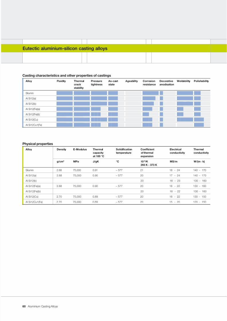
7/31/2019 Aluminium Casting Alloys EnglishVersion 2011
http://slidepdf.com/reader/full/aluminium-casting-alloys-englishversion-2011 60/102
Aluminium Casting Alloys
Eutectic aluminium-silicon casting alloys
Casting characteristics and other properties of castings
Alloy Fluidity Thermal Pressure As-cast Ageability Corrosion Decorative Weldability Polishabilitycrack tightness state resistance anodisationstability
Silumin
Al Si12(a)
Al Si12(b)
Al Si12(Fe)(a)
Al Si12(Fe)(b)
Al Si12(Cu)
Al Si12Cu1(Fe)
Physical properties
Alloy Density E-Modulus Thermal Solidication Coefcient Electrical Thermalcapacity temperature of thermal conductivity conductivityat 100 °C expansion
g/cm 3 MPa J/gK °C 10 -6 /K MS/m W/(m . k)293 K - 373 K
Silumin 2.68 75,000 0.91 ~ 577 21 18 - 24 140 - 170
Al Si12(a) 2.68 75,000 0.90 ~ 577 20 17 - 24 140 - 170
Al Si12(b) 20 16 - 23 130 - 160
Al Si12(Fe)(a) 2.68 75,000 0.90 ~ 577 20 16 - 22 130 - 160
Al Si12(Fe)(b) 20 16 - 22 130 - 160
Al Si12(Cu) 2.70 75,000 0.89 ~ 577 20 16 - 22 130 - 150
Al Si12Cu1(Fe) 2.70 75,000 0.89 ~ 577 20 15 - 20 120 - 150
60
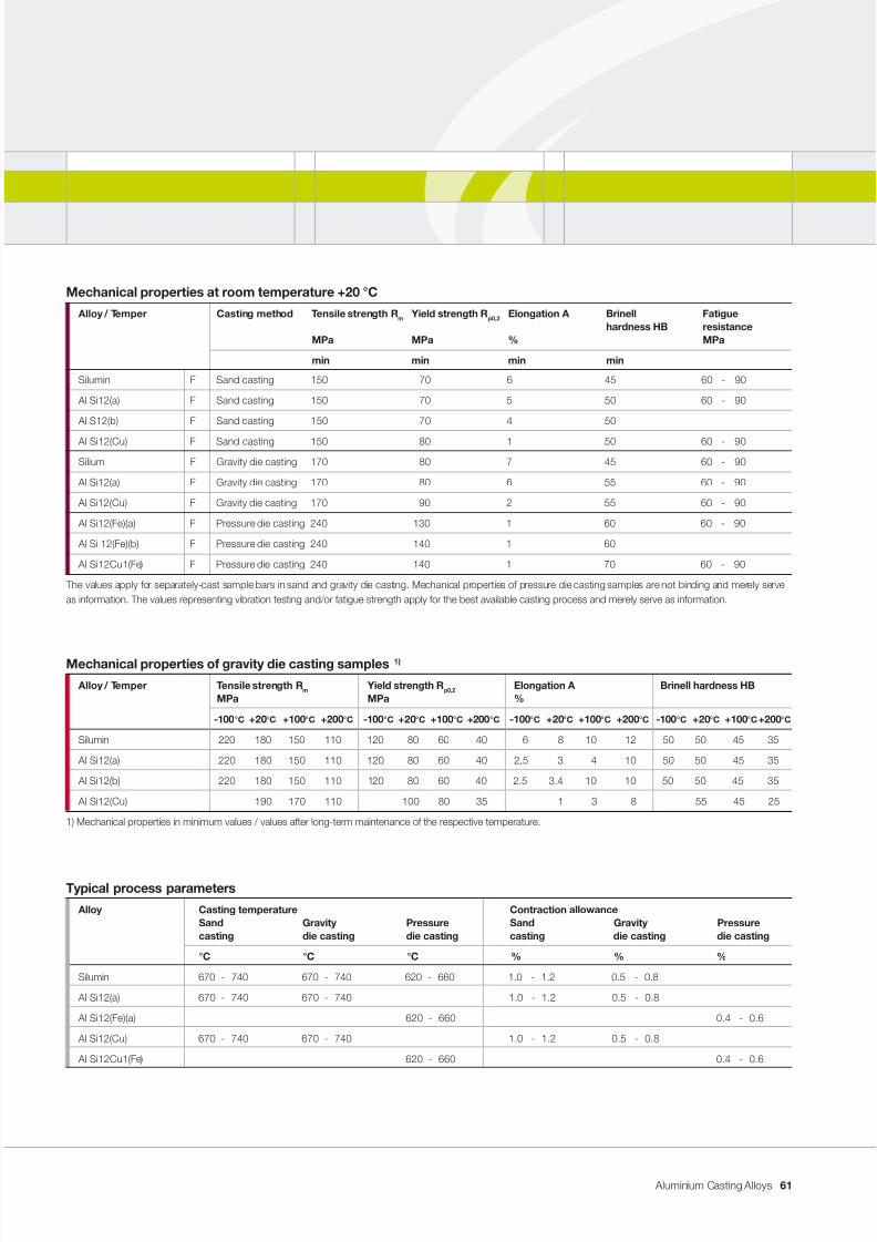
7/31/2019 Aluminium Casting Alloys EnglishVersion 2011
http://slidepdf.com/reader/full/aluminium-casting-alloys-englishversion-2011 61/102
Aluminium Casting Alloys
Mechanical properties at room temperature +20 °C
Alloy / Temper Casting method Tensile strength R m Yield strength R p0,2 Elongation A Brinell Fatiguehardness HB resistance
MPa MPa % MPa
min min min min
Silumin F Sand casting 150 70 6 45 60 - 90
Al Si12(a) F Sand casting 150 70 5 50 60 - 90
Al S12(b) F Sand casting 150 70 4 50
Al Si12(Cu) F Sand casting 150 80 1 50 60 - 90
Silium F Gravity die casting 170 80 7 45 60 - 90
Al Si12(a) F Gravity die casting 170 80 6 55 60 - 90
Al Si12(Cu) F Gravity die casting 170 90 2 55 60 - 90
Al Si12(Fe)(a) F Pressure die casting 240 130 1 60 60 - 90
Al Si 12(Fe)(b) F Pressure die casting 240 140 1 60
Al Si12Cu1(Fe) F Pressure die casting 240 140 1 70 60 - 90
The values apply for separately-cast sample bars in sand and gravity die casting. Mechanical properties of pressure die casting samples are not binding and merely serveas information. The values representing vibration testing and/or fatigue strength apply for the best available casting process and merely serve as information.
Mechanical properties of gravity die casting samples 1)
Alloy / Temper Tensile strength R m Yield strength R p0,2 Elongation A Brinell hardness HBMPa MPa %
-100 °C +20 °C +100 °C +200 °C -100 °C +20 °C +100 °C +200 °C -100 °C +20 °C +100 °C +200 °C -100 °C +20 °C +100 °C +200 °C
Silumin 220 180 150 110 120 80 60 40 6 8 10 12 50 50 45 35
Al Si12(a) 220 180 150 110 120 80 60 40 2,5 3 4 10 50 50 45 35
Al Si12(b) 220 180 150 110 120 80 60 40 2.5 3.4 10 10 50 50 45 35
Al Si12(Cu) 190 170 110 100 80 35 1 3 8 55 45 25
1) Mechanical properties in minimum values / values after long-term maintenance of the respective temperature.
Typical process parameters
Alloy Casting temperature Contraction allowanceSand Gravity Pressure Sand Gravity Pressurecasting die casting die casting casting die casting die casting
°C °C °C % % %
Silumin 670 - 740 670 - 740 620 - 660 1.0 - 1.2 0.5 - 0.8
Al Si12(a) 670 - 740 670 - 740 1.0 - 1.2 0.5 - 0.8
Al Si12(Fe)(a) 620 - 660 0.4 - 0.6
Al Si12(Cu) 670 - 740 670 - 740 1.0 - 1.2 0.5 - 0.8
Al Si12Cu1(Fe) 620 - 660 0.4 - 0.6
61
7/31/2019 Aluminium Casting Alloys EnglishVersion 2011
http://slidepdf.com/reader/full/aluminium-casting-alloys-englishversion-2011 62/102
Aluminium Casting Alloys
Application notes
Universal aluminium casting alloy with
medium strength; in part, very good elon-
gation and very good ow properties.
Suitable for thin-walled, complicated,
pressure-tight, vibration- and impact-
resistant constructions.
Properties and processing
From the range of AlSi casting alloys,
this type of alloy containing 13 % silicon
has the best uidity. In some respects,
the behaviour of the casting alloys in this
range represents a special case. Some
advice is provided below.
In the case of free solidication, e.g. a
dense, bevel-shaped surface, the so-
called “hammer blow”, forms on the top
of the ingot. This type of solidication is
“shell-forming”, i.e. the crystallisation of
the subsequent casting begins with the
formation of a solid shell which then grows
towards the middle of the cast wall. In
this type of casting alloy, there are only
two states, i.e. “solid” and “liquid”. Full
solidication of a casting takes placeat the eutectic temperature of approx.
577 °C). During the solidication process,
the volume can contract by up to 7 %.
The shell thickness does not decrease.
If the ow of liquid metal is interrupted
in the middle wall region during feeding,
a coarse cavity can evolve. (Additional
notes also provided in the sections en-
titled “Inuencing the microstructural
formation of aluminium castings” and
“Avoiding casting defects”.)
This type of aluminium casting alloy can
only be modied with sodium. Sodium
modication is indicated for sand cast-
ings and gravity die castings if particular
requirements are placed on elongation
of the microstructure (see Figure 2). As
a general rule, casting alloys for use in
sand and gravity die casting are offered
in a slightly modied version. Chemical
resistance as well as resistance to weath-
ering and a marine climate increase with
the purity of the casting alloy used. A pri-
mary silicon casting alloy thus meets the
highest requirements in a variety of elds
of application, e.g. in the food industry
or in shipbuilding. The elongation of the
cast structure is signicantly determined
by the iron content and other impurities.
The demand for high proof stress values
in the casting often requires the use ofprimary casting alloys with the lowest
possible content of iron and impurities.
Heat treatment
In the case of sand and gravity die cast-
ings made from casting alloys low in
Cu and Mg, a selective improvement
in ductility can be achieved. This is ef-
fected by means of solution annealing at
520-530 °C with subsequent quenchingin cold water.
Comments
The DIN EN 1676 and DIN EN 1706
standards allow a very wide range of
major alloying elements – silicon from
10.5 to 13.5 %. The practical range for
the silicon content is from 12.5 to 13.5
and, in a slightly hypoeutectic range of
10.5 to 11.2 %. However, these two al-
loys display entirely different solidication
behaviour. The intermediate range, with
approx. 11.5 to 12.5 % silicon, runs the
risk of shrinkage cavities. Casting alloys
in this critical range are not offered. Even
a blend of these different yet similar-
sounding alloys is not recommended.
Eutectic aluminium-silicon casting alloys
62
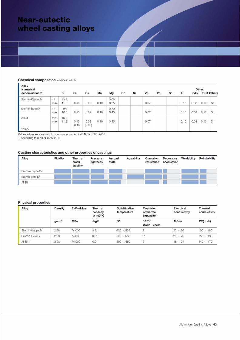
7/31/2019 Aluminium Casting Alloys EnglishVersion 2011
http://slidepdf.com/reader/full/aluminium-casting-alloys-englishversion-2011 63/102
Aluminium Casting Alloys
Near-eutecticwheel casting alloys
Casting characteristics and other properties of castings
Alloy Fluidity Thermal Pressure As-cast Ageability Corrosion Decorative Weldability Polishabilitycrack tightness state resistance anodisationstability
Silumin-Kappa Sr
Silumin-Beta Sr
Al Si11
Physical properties
Alloy Density E-Modulus Thermal Solidication Coefcient Electrical Thermalcapacity temperature of thermal conductivity conductivityat 100 °C expansion
g/cm 3 MPa J/gK °C 10 -6 /K MS/m W/(m . k)293 K - 373 K
Silumin-Kappa Sr 2.68 74,000 0.91 600 - 555 21 20 - 26 150 - 180
Silumin-Beta Sr 2.68 74,000 0.91 600 - 550 21 20 - 26 150 - 180
Al Si11 2.68 74,000 0.91 600 - 550 21 18 - 24 140 - 170
Chemical composition (all data in wt.-%)
AlloyNumerical Other
denomination 1) Si Fe Cu Mn Mg Cr Ni Zn Pb Sn Ti
Silumin-Kappa Sr min 10.5 0.05max 11.0 0.15 0.02 0.10 0.25 0.07 0.15 0.03 0.10 Sr
Silumin-Beta Sr min 9.0 0.20max 10.5 0.15 0.02 0.10 0.45 0.07 0.15 0.03 0.10 Sr
Al Si11 min 10.0max 11.8 0.15 0.03 0.10 0.45 0.07 0.15 0.03 0.10 Sr(0.19) (0.05)
44000
Values in brackets are valid for castings according to DIN EN 1706: 20101) According to DIN EN 1676: 2010
Otherstotalindiv.
63
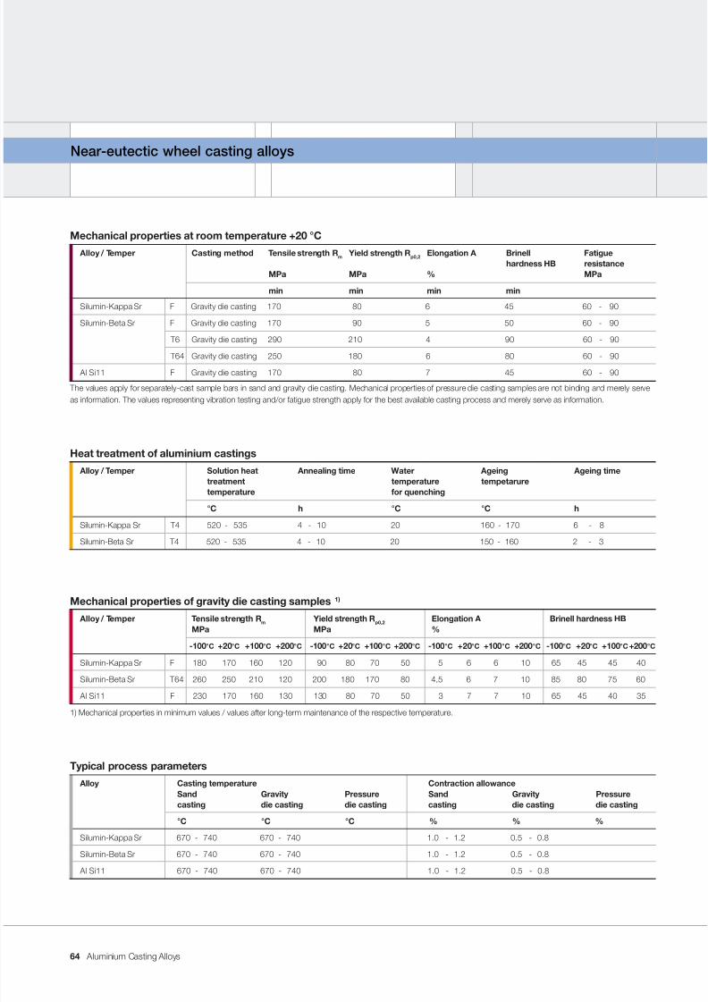
7/31/2019 Aluminium Casting Alloys EnglishVersion 2011
http://slidepdf.com/reader/full/aluminium-casting-alloys-englishversion-2011 64/102
Aluminium Casting Alloys
Near-eutectic wheel casting alloys
Mechanical properties at room temperature +20 °C
Alloy / Temper Casting method Tensile strength R m Yield strength R p0,2 Elongation A Brinell Fatiguehardness HB resistance
MPa MPa % MPa
min min min min
Silumin-Kappa Sr F Gravity die casting 170 80 6 45 60 - 90
Silumin-Beta Sr F Gravity die casting 170 90 5 50 60 - 90
T6 Gravity die casting 290 210 4 90 60 - 90
T64 Gravity die casting 250 180 6 80 60 - 90
Al Si11 F Gravity die casting 170 80 7 45 60 - 90
The values apply for separately-cast sample bars in sand and gravity die casting. Mechanical properties of pressure die casting samples are not binding and merely serveas information. The values representing vibration testing and/or fatigue strength apply for the best available casting process and merely serve as information.
Mechanical properties of gravity die casting samples 1)
Alloy / Temper Tensile strength R m Yield strength R p0,2 Elongation A Brinell hardness HBMPa MPa %
-100 °C +20 °C +100 °C +200 °C -100 °C +20 °C +100 °C +200 °C -100 °C +20 °C +100 °C +200 °C -100 °C +20 °C +100 °C +200 °C
Silumin-Kappa Sr F 180 170 160 120 90 80 70 50 5 6 6 10 65 45 45 40
Silumin-Beta Sr T64 260 250 210 120 200 180 170 80 4,5 6 7 10 85 80 75 60
Al Si11 F 230 170 160 130 130 80 70 50 3 7 7 10 65 45 40 35
1) Mechanical properties in minimum values / values after long-term maintenance of the respective temperature.
Typical process parameters
Alloy Casting temperature Contraction allowanceSand Gravity Pressure Sand Gravity Pressurecasting die casting die casting casting die casting die casting
°C °C °C % % %
Silumin-Kappa Sr 670 - 740 670 - 740 1.0 - 1.2 0.5 - 0.8
Silumin-Beta Sr 670 - 740 670 - 740 1.0 - 1.2 0.5 - 0.8
Al Si11 670 - 740 670 - 740 1.0 - 1.2 0.5 - 0.8
Heat treatment of aluminium castings
Alloy / Temper Solution heat Annealing time Water Ageing Ageing timetreatment temperature tempetaruretemperature for quenching
°C h °C °C h
Silumin-Kappa Sr T4 520 - 535 4 - 10 20 160 - 170 6 - 8Silumin-Beta Sr T4 520 - 535 4 - 10 20 150 - 160 2 - 3
64
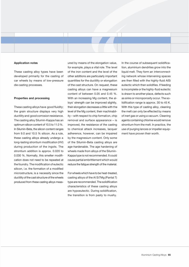
7/31/2019 Aluminium Casting Alloys EnglishVersion 2011
http://slidepdf.com/reader/full/aluminium-casting-alloys-englishversion-2011 65/102
Aluminium Casting Alloys
Application notes
These casting alloy types have been
developed primarily for the casting of
car wheels by means of low-pressure
die casting processes.
Properties and processing
These casting alloys have good uidity;
the grain structure displays very high
ductility and good corrosion resistance.
The casting alloy Silumin-Kappa has an
optimum silicon content of 10.5 to 11.0 %.
In Silumin-Beta, the silicon content ranges
from 9.0 and 10.5 % silicon. As a rule,
these casting alloys already undergo a
long-lasting strontium modication (HV)
during production of the ingots. The
strontium addition is approx. 0.020 to
0.030 %. Normally, this smelter modi-
cation does not need to be repeated at
the foundry. The modication of eutectic
silicon, i.e. the formation of a modied
microstructure, is a necessity since the
ductility of the cast structure of the wheels
produced from these casting alloys meas-
ured by means of the elongation value,
for example, plays a vital role. The level
of the iron content and the level of the
other additions are particularly important
quantities for the ductility or elongation
of the cast structure. On request, these
casting alloys can have a magnesium
content of between 0.05 and 0.45 %.With an increasing Mg content, the al-
loys‘ strength can be improved slightly,
their elongation decreases a little with the
level of the Mg content, their machinabil-
ity – with respect to chip formation, chip
removal and surface appearance – is
improved, the resistance of the casting
to chemical attack increases, lacquer
adherence, however, can be impaired
by the magnesium content. Only some
of the Silumin-Beta casting alloys are
age-hardenable. The age hardening of
wheels made from alloys of the Silumin-
Kappa type is not recommended. It could
cause partial embrittlement which would
reduce the fatigue strength of the material.
For wheels which have to be heat-treated,
casting alloys of the Al Si7Mg (Pantal 7)
type are recommended. The solidication
characteristics of these casting alloysare hypoeutectic. During solidication,
the transition is from pasty to mushy.
In the course of subsequent solidica-
tion, aluminium dendrites grow into the
liquid melt. They form an interconnect-
ing network whose intervening spaces
are then lled with the highly-uid AlSi
eutectic which then solidies. If feeding
is incomplete or the highly-uid eutectic
is drawn to another place, defects suchas sinks or microporosity occur. The so-
lidication range is approx. 30 to 45 K.
With this type of casting alloy, cleaning
the melt can only be effected by means
of inert gas or using a vacuum. Cleaning
agents containing chlorine would remove
strontium from the melt. In practice, the
use of purging lances or impeller equip-
ment have proven their worth.
65
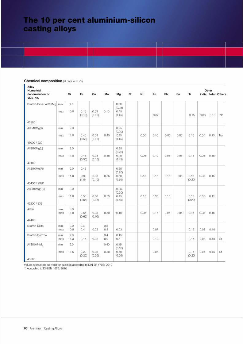
7/31/2019 Aluminium Casting Alloys EnglishVersion 2011
http://slidepdf.com/reader/full/aluminium-casting-alloys-englishversion-2011 66/102
Aluminium Casting Alloys
The 10 per cent aluminium-siliconcasting alloys
Chemical composition (all data in wt.-%)
AlloyNumerical Other
denomination 1) / Si Fe Cu Mn Mg Cr Ni Zn Pb Sn Ti VDS-No.
Silumin-Beta / Al Si9Mg min 9.0 0.30 (0.25)
max 10.0 0.15 0.03 0.10 0.45 (0.19) (0.05) (0.45) 0.07 0.15 0.03 0.10 Na
43300
Al Si10Mg(a) min 9.0 0.25 (0.20)
max 11.0 0.40 0.03 0.45 0.45 0.05 0.10 0.05 0.05 0.15 0.05 0.15 Na (0.55) (0.05) (0.45)
43000 / 239
Al Si10Mg(b) min 9.0 0.25 (0.20)
max 11.0 0.45 0.08 0.45 0.45 0.05 0.10 0.05 0.05 0.15 0.05 0.15 (0.55) (0.10) (0.45)
43100
Al Si10Mg(Fe) min 9.0 0.45 0.25 (0.20)
max 11.0 0.9 0.08 0.55 0.50 0.15 0.15 0.15 0.05 0.15 0.05 0.15
(1.0) (0.10) (0.50) (0.20)43400 / 239D
Al Si10Mg(Cu) min 9.0 0.25 (0.20)
max 11.0 0.55 0.30 0.55 0.45 0.15 0.35 0.10 0.15 0.05 0.15(0.65) (0.35) (0.45) (0.20)
43200 / 233
Al Si9 min 8.0max 11.0 0.55 0.08 0.50 0.10 0.05 0.15 0.05 0.05 0.15 0.05 0.15
(0.65) (0.10)44400
Silumin-Delta min 9.0 0.3 0.3max 10.5 0.4 0.02 0.4 0.03 0.07 0.15 0.03 0.10
Silumin-Gamma min 9.0 0.4 0.15max 11.3 0.15 0.02 0.9 0.6 0.10 0.15 0.03 0.10 Sr
Al Si10MnMg min 9.0 0.40 0.15 (0.10)
max 11.5 0.20 0.03 0.80 0.60 0.07 0.15 0.05 0.15 Sr (0.25) (0.05) (0.60) (0.20)
43500
Values in brackets are valid for castings according to DIN EN 1706: 20101) According to DIN EN 1676: 2010
Otherstotalindiv.
66
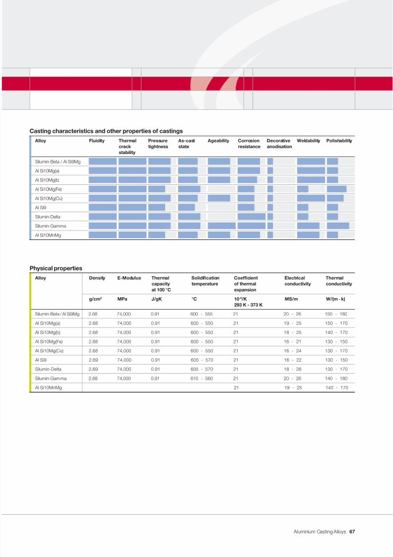
7/31/2019 Aluminium Casting Alloys EnglishVersion 2011
http://slidepdf.com/reader/full/aluminium-casting-alloys-englishversion-2011 67/102
Aluminium Casting Alloys
Casting characteristics and other properties of castings
Alloy Fluidity Thermal Pressure As-cast Ageability Corrosion Decorative Weldability Polishabilitycrack tightness state resistance anodisationstability
Silumin-Beta / Al Si9Mg
Al Si10Mg(a)
Al Si10Mg(b)
Al Si10Mg(Fe)
Al Si10Mg(Cu)
Al Si9
Silumin-Delta
Silumin-Gamma
Al Si10MnMg
Physical properties
Alloy Density E-Modulus Thermal Solidication Coefcient Electrical Thermalcapacity temperature of thermal conductivity conductivityat 100 °C expansion
g/cm 3 MPa J/gK °C 10 -6 /K MS/m W/(m . k)293 K - 373 K
Silumin-Beta / Al Si9Mg 2.68 74,000 0.91 600 - 555 21 20 - 26 150 - 180
Al Si10Mg(a) 2.68 74,000 0.91 600 - 550 21 19 - 25 150 - 170
Al Si10Mg(b) 2.68 74,000 0.91 600 - 550 21 18 - 25 140 - 170
Al Si10Mg(Fe) 2.68 74,000 0.91 600 - 550 21 16 - 21 130 - 150
Al Si10Mg(Cu) 2.68 74,000 0.91 600 - 550 21 16 - 24 130 - 170
Al Si9 2.69 74,000 0.91 605 - 570 21 16 - 22 130 - 150
Silumin-Delta 2.69 74,000 0.91 605 - 570 21 18 - 26 130 - 170
Silumin-Gamma 2.68 74,000 0.91 610 - 560 21 20 - 26 140 - 180
Al Si10MnMg 21 19 - 25 140 - 170
67
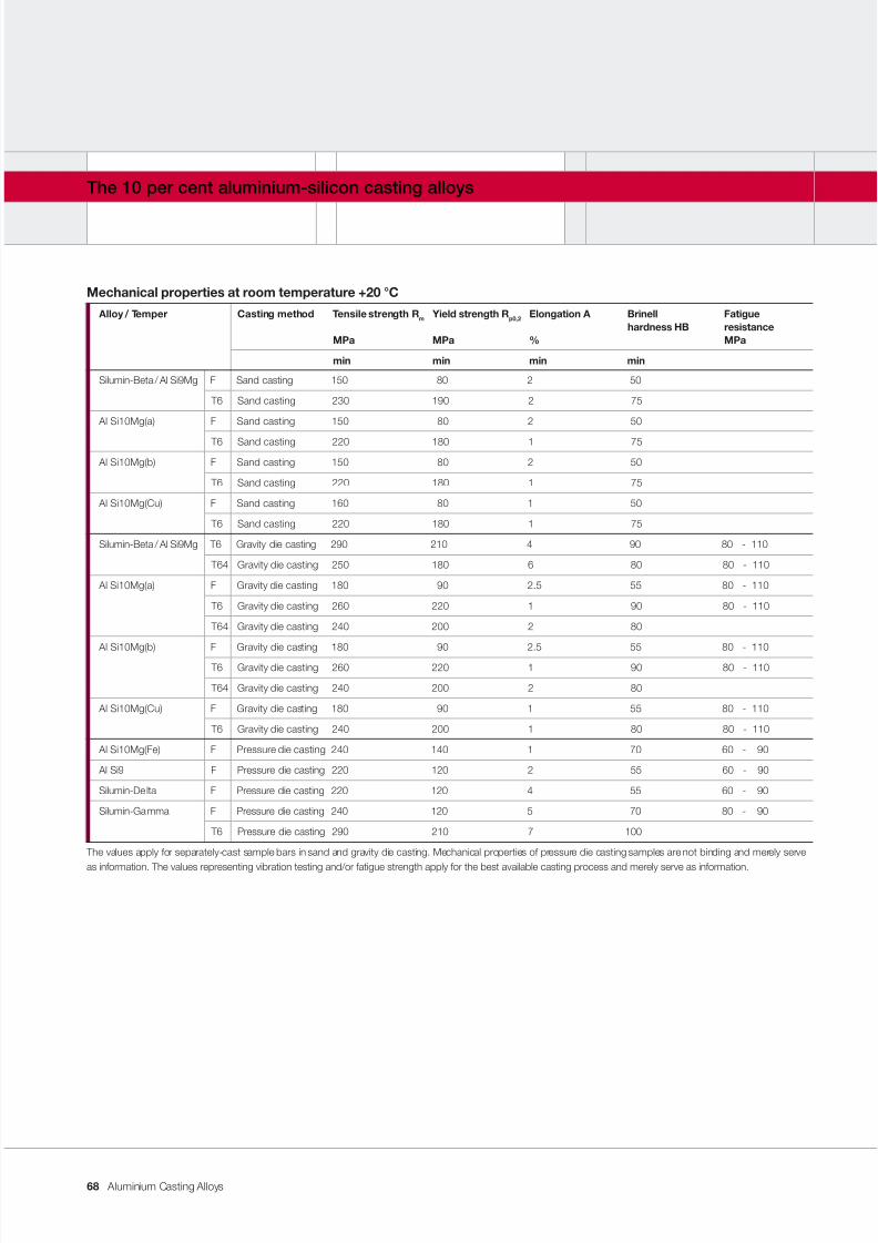
7/31/2019 Aluminium Casting Alloys EnglishVersion 2011
http://slidepdf.com/reader/full/aluminium-casting-alloys-englishversion-2011 68/102
Aluminium Casting Alloys
The 10 per cent aluminium-silicon casting alloys
Mechanical properties at room temperature +20 °C
Alloy / Temper Casting method Tensile strength R m Yield strength R p0,2 Elongation A Brinell Fatiguehardness HB resistance
MPa MPa % MPa
min min min min
Silumin-Beta / Al Si9Mg F Sand casting 150 80 2 50
T6 Sand casting 230 190 2 75
Al Si10Mg(a) F Sand casting 150 80 2 50
T6 Sand casting 220 180 1 75
Al Si10Mg(b) F Sand casting 150 80 2 50
T6 Sand casting 220 180 1 75
Al Si10Mg(Cu) F Sand casting 160 80 1 50
T6 Sand casting 220 180 1 75
Silumin-Beta / Al Si9Mg T6 Gravity die casting 290 210 4 90 80 - 110
T64 Gravity die casting 250 180 6 80 80 - 110
Al Si10Mg(a) F Gravity die casting 180 90 2.5 55 80 - 110
T6 Gravity die casting 260 220 1 90 80 - 110
T64 Gravity die casting 240 200 2 80
Al Si10Mg(b) F Gravity die casting 180 90 2.5 55 80 - 110
T6 Gravity die casting 260 220 1 90 80 - 110
T64 Gravity die casting 240 200 2 80
Al Si10Mg(Cu) F Gravity die casting 180 90 1 55 80 - 110
T6 Gravity die casting 240 200 1 80 80 - 110
Al Si10Mg(Fe) F Pressure die casting 240 140 1 70 60 - 90
Al Si9 F Pressure die casting 220 120 2 55 60 - 90
Silumin-Delta F Pressure die casting 220 120 4 55 60 - 90
Silumin-Gamma F Pressure die casting 240 120 5 70 80 - 90
T6 Pressure die casting 290 210 7 100
The values apply for separately-cast sample bars in sand and gravity die casting. Mechanical properties of pressure die casting samples are not binding and merely serve
as information. The values representing vibration testing and/or fatigue strength apply for the best available casting process and merely serve as information.
68
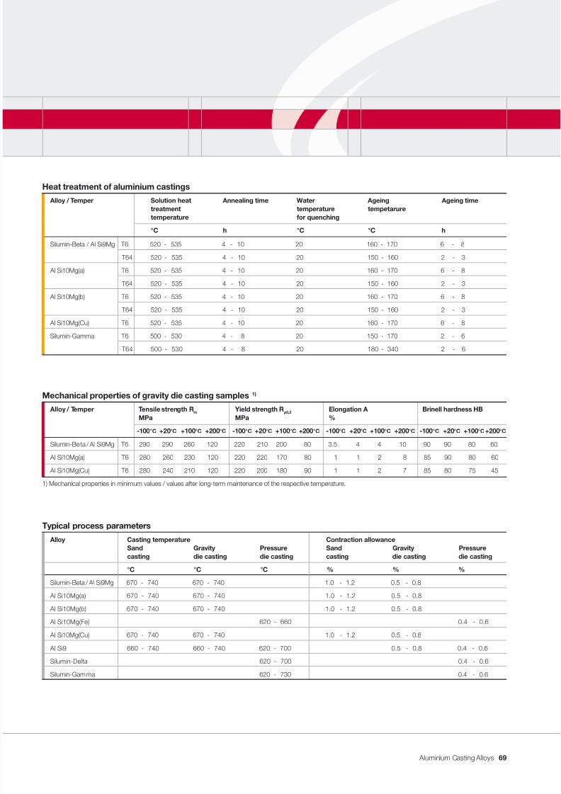
7/31/2019 Aluminium Casting Alloys EnglishVersion 2011
http://slidepdf.com/reader/full/aluminium-casting-alloys-englishversion-2011 69/102
Aluminium Casting Alloys
Typical process parameters
Alloy Casting temperature Contraction allowanceSand Gravity Pressure Sand Gravity Pressure
casting die casting die casting casting die casting die casting
°C °C °C % % %
Silumin-Beta / Al Si9Mg 670 - 740 670 - 740 1.0 - 1.2 0.5 - 0.8
Al Si10Mg(a) 670 - 740 670 - 740 1.0 - 1.2 0.5 - 0.8
Al Si10Mg(b) 670 - 740 670 - 740 1.0 - 1.2 0.5 - 0.8
Al Si10Mg(Fe) 620 - 660 0.4 - 0.6
Al Si10Mg(Cu) 670 - 740 670 - 740 1.0 - 1.2 0.5 - 0.8
Al Si9 660 - 740 660 - 740 620 - 700 0.5 - 0.8 0.4 - 0.6
Silumin-Delta 620 - 700 0.4 - 0.6
Silumin-Gamma 620 - 730 0.4 - 0.6
Mechanical properties of gravity die casting samples 1)
Alloy / Temper Tensile strength R m Yield strength R p0,2 Elongation A Brinell hardness HB
MPa MPa %
-100 °C +20 °C +100 °C +200 °C -100 °C +20 °C +100 °C +200 °C -100 °C +20 °C +100 °C +200 °C -100 °C +20 °C +100 °C +200 °C
Silumin-Beta / Al Si9Mg T6 290 290 260 120 220 210 200 80 3.5 4 4 10 90 90 80 60
Al Si10Mg(a) T6 280 260 230 120 220 220 170 80 1 1 2 8 85 90 80 60
Al Si10Mg(Cu) T6 280 240 210 120 220 200 180 90 1 1 2 7 85 80 75 45
1) Mechanical properties in minimum values / values after long-term maintenance of the respective temperature.
Heat treatment of aluminium castings
Alloy / Temper Solution heat Annealing time Water Ageing Ageing timetreatment temperature tempetaruretemperature for quenching
°C h °C °C h
Silumin-Beta / Al Si9Mg T6 520 - 535 4 - 10 20 160 - 170 6 - 8
T64 520 - 535 4 - 10 20 150 - 160 2 - 3
Al Si10Mg(a) T6 520 - 535 4 - 10 20 160 - 170 6 - 8
T64 520 - 535 4 - 10 20 150 - 160 2 - 3
Al Si10Mg(b) T6 520 - 535 4 - 10 20 160 - 170 6 - 8
T64 520 - 535 4 - 10 20 150 - 160 2 - 3
Al Si10Mg(Cu) T6 520 - 535 4 - 10 20 160 - 170 6 - 8
Silumin-Gamma T6 500 - 530 4 - 8 20 150 - 170 2 - 6
T64 500 - 530 4 - 8 20 180 - 340 2 - 6
69
7/31/2019 Aluminium Casting Alloys EnglishVersion 2011
http://slidepdf.com/reader/full/aluminium-casting-alloys-englishversion-2011 70/102
Aluminium Casting Alloys
Application notes
This important group of casting alloys
is used for castings with medium wall
thicknesses which require higher, to the
highest strength properties. The elds of
application comprise mechanical and
electrical engineering, the food industryas well as in engine and motor vehicle
construction. Silumin-Beta casting alloys
are also used for car wheels. Silumin-
Gamma is a heat-treatable high-pressure
die casting alloy. However, successful
treatment requires the use of an adequate
casting process (e.g. vacuum-assisted
high-pressure die casting).
Properties and processing
The uidities of these casting alloys are
still good. Heat-treatable castings made
from alloys containing magnesium dis-
play particularly good machinability. With
increasing purity, the ductility of the cast
structure also increases. Where the re-quirements on corrosion resistance are
high, high-purity grades are selected.
Sand and gravity die castings can be
articially aged. In doing so, however,
ductility decreases. The solidication
characteristics of this group of casting
alloys are hypoeutectic. During the so-
lidication process, aluminium dendrites
grow into the melt rst. The highly-uid
AlSi eutectic then penetrates the inter-
vening spaces of the network and clamps
the microstructural framework together.
If the feeding of the remaining eutectic
melt is hindered in any way, defects such
as sinks or micro/macrocavities occur.
This causes porous areas and also leads
to a weakening of the structural cross-
section. During casting, therefore, atten-
tion must be paid to ensure good feed-
ing and, as far as possible, controlled
solidication. The solidication range
amounts to approx. 45 K.
Where requirements on elongation orductility are higher, modication of the
melt is recommended. The casting alloys
for use in gravity die casting are modi-
ed with sodium or strontium. For sand
casting, modication with sodium only
is recommended. As a general rule, the
casting alloys for sand and gravity die
casting are offered in versions which can
be easily modied.
The 10 per cent aluminium-silicon casting alloys
70
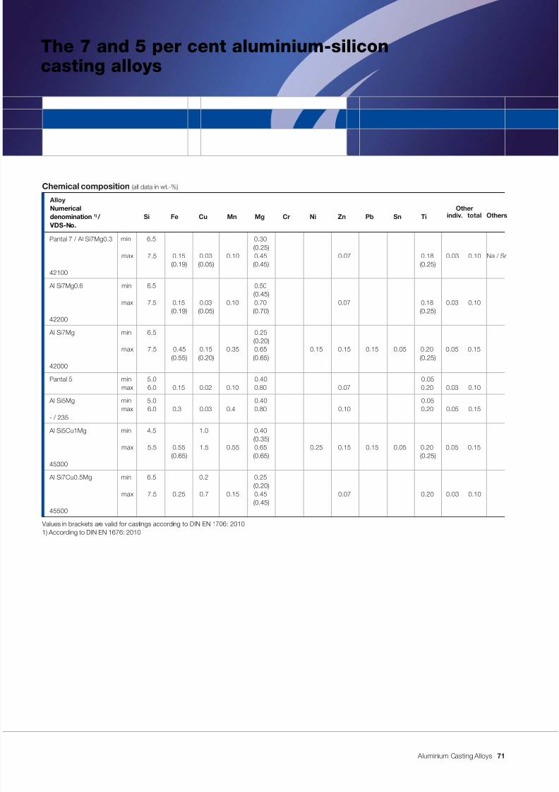
7/31/2019 Aluminium Casting Alloys EnglishVersion 2011
http://slidepdf.com/reader/full/aluminium-casting-alloys-englishversion-2011 71/102
Aluminium Casting Alloys
The 7 and 5 per cent aluminium-siliconcasting alloys
Chemical composition (all data in wt.-%)
AlloyNumerical Other
denomination 1) / Si Fe Cu Mn Mg Cr Ni Zn Pb Sn Ti VDS-No.
Pantal 7 / Al Si7Mg0.3 min 6.5 0.30 (0.25)
max 7.5 0.15 0.03 0.10 0.45 0.07 0.18 0.03 0.10 Na / Sr (0.19) (0.05) (0.45) (0.25)
42100
Al Si7Mg0.6 min 6.5 0.50 (0.45)
max 7.5 0.15 0.03 0.10 0.70 0.07 0.18 0.03 0.10(0.19) (0.05) (0.70) (0.25)
42200
Al Si7Mg min 6.5 0.25 (0.20)
max 7.5 0.45 0.15 0.35 0.65 0.15 0.15 0.15 0.05 0.20 0.05 0.15(0.55) (0.20) (0.65) (0.25)
42000
Pantal 5 min 5.0 0.40 0.05max 6.0 0.15 0.02 0.10 0.80 0.07 0.20 0.03 0.10
Al Si5Mg min 5.0 0.40 0.05max 6.0 0.3 0.03 0.4 0.80 0.10 0.20 0.05 0.15
- / 235
Al Si5Cu1Mg min 4.5 1.0 0.40 (0.35)
max 5.5 0.55 1.5 0.55 0.65 0.25 0.15 0.15 0.05 0.20 0.05 0.15(0.65) (0.65) (0.25)
45300
Al Si7Cu0.5Mg min 6.5 0.2 0.25 (0.20)
max 7.5 0.25 0.7 0.15 0.45 0.07 0.20 0.03 0.10(0.45)
45500
Values in brackets are valid for castings according to DIN EN 1706: 20101) According to DIN EN 1676: 2010
Otherstotalindiv.
71
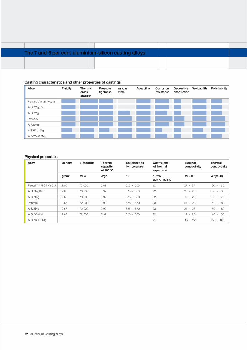
7/31/2019 Aluminium Casting Alloys EnglishVersion 2011
http://slidepdf.com/reader/full/aluminium-casting-alloys-englishversion-2011 72/102
Aluminium Casting Alloys
The 7 and 5 per cent aluminium-silicon casting alloys
Casting characteristics and other properties of castings
Alloy Fluidity Thermal Pressure As-cast Ageability Corrosion Decorative Weldability Polishabilitycrack tightness state resistance anodisationstability
Pantal 7 / Al Si7Mg0.3
Al Si7Mg0.6
Al Si7Mg
Pantal 5
Al Si5Mg
Al Si5Cu1Mg
Al Si7Cu0.5Mg
Physical properties
Alloy Density E-Modulus Thermal Solidication Coefcient Electrical Thermalcapacity temperature of thermal conductivity conductivityat 100 °C expansion
g/cm 3 MPa J/gK °C 10 -6 /K MS/m W/(m . k)293 K - 373 K
Pantal 7 / Al Si7Mg0.3 2.66 73,000 0.92 625 - 550 22 21 - 27 160 - 180
Al Si7Mg0.6 2.66 73,000 0.92 625 - 550 22 20 - 26 150 - 180
Al Si7Mg 2.66 73,000 0.92 625 - 550 22 19 - 25 150 - 170
Pantal 5 2.67 72,000 0.92 625 - 550 23 21 - 29 150 - 180
Al Si5Mg 2.67 72,000 0.92 625 - 550 23 21 - 26 150 - 180
Al Si5Cu1Mg 2.67 72,000 0.92 625 - 550 22 19 - 23 140 - 150
Al Si7Cu0.5Mg 22 16 - 22 150 - 165
72
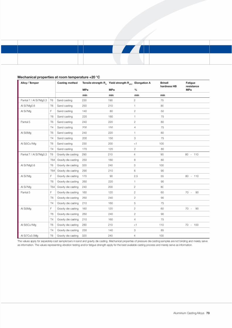
7/31/2019 Aluminium Casting Alloys EnglishVersion 2011
http://slidepdf.com/reader/full/aluminium-casting-alloys-englishversion-2011 73/102
Aluminium Casting Alloys
Mechanical properties at room temperature +20 °C
Alloy / Temper Casting method Tensile strength R m Yield strength R p0,2 Elongation A Brinell Fatiguehardness HB resistance
MPa MPa % MPa
min min min min
Pantal 7 / Al Si7Mg0.3 T6 Sand casting 230 190 2 75
Al Si7Mg0.6 T6 Sand casting 250 210 1 85
Al Si7Mg F Sand casting 140 80 2 50
T6 Sand casting 220 180 1 75
Pantal 5 T6 Sand casting 240 220 2 80
T4 Sand casting 200 150 4 75
Al Si5Mg T6 Sand casting 240 220 1 80
T4 Sand casting 200 150 3 75
Al Si5Cu1Mg T6 Sand casting 230 200 <1 100
T4 Sand casting 170 120 2 80
Pantal 7 / Al Si7Mg0.3 T6 Gravity die casting 290 210 4 90 80 - 110
T64 Gravity die casting 250 180 8 80
Al Si7Mg0.6 T6 Gravity die casting 320 240 3 100
T64 Gravity die casting 290 210 6 90
Al Si7Mg F Gravity die casting 170 90 2.5 55 80 - 110
T6 Gravity die casting 260 220 1 90
Al Si7Mg T64 Gravity die casting 240 200 2 80
Pantal 5 F Gravity die casting 160 120 2 60 70 - 90
T6 Gravity die casting 260 240 2 90
T4 Gravity die casting 210 160 5 75
Al Si5Mg F Gravity die casting 160 120 2 60 70 - 90
T6 Gravity die casting 260 240 2 90
T4 Gravity die casting 210 160 4 75
Al Si5Cu1Mg T6 Gravity die casting 280 210 <1 110 70 - 100
T4 Gravity die casting 230 140 3 85
Al Si7Cu0.5Mg T6 Gravity die casting 320 240 4 100
The values apply for separately-cast sample bars in sand and gravity die casting. Mechanical properties of pressure die casting samples are not binding and merely serveas information. The values representing vibration testing and/or fatigue strength apply for the best available casting process and merely serve as information.
73
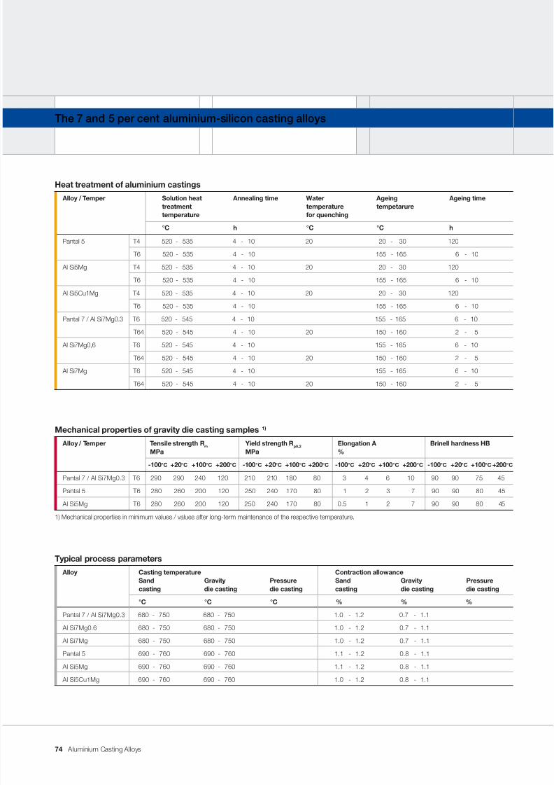
7/31/2019 Aluminium Casting Alloys EnglishVersion 2011
http://slidepdf.com/reader/full/aluminium-casting-alloys-englishversion-2011 74/102
Aluminium Casting Alloys
The 7 and 5 per cent aluminium-silicon casting alloys
Mechanical properties of gravity die casting samples 1)
Alloy / Temper Tensile strength R m Yield strength R p0,2 Elongation A Brinell hardness HBMPa MPa %
-100 °C +20 °C +100 °C +200 °C -100 °C +20 °C +100 °C +200 °C -100 °C +20 °C +100 °C +200 °C -100 °C +20 °C +100 °C +200 °C
Pantal 7 / Al Si7Mg0.3 T6 290 290 240 120 210 210 180 80 3 4 6 10 90 90 75 45
Pantal 5 T6 280 260 200 120 250 240 170 80 1 2 3 7 90 90 80 45
Al Si5Mg T6 280 260 200 120 250 240 170 80 0.5 1 2 7 90 90 80 45
1) Mechanical properties in minimum values / values after long-term maintenance of the respective temperature.
Typical process parameters
Alloy Casting temperature Contraction allowanceSand Gravity Pressure Sand Gravity Pressurecasting die casting die casting casting die casting die casting
°C °C °C % % %
Pantal 7 / Al Si7Mg0.3 680 - 750 680 - 750 1.0 - 1.2 0.7 - 1.1
Al Si7Mg0.6 680 - 750 680 - 750 1.0 - 1.2 0.7 - 1.1
Al Si7Mg 680 - 750 680 - 750 1.0 - 1.2 0.7 - 1.1
Pantal 5 690 - 760 690 - 760 1.1 - 1.2 0.8 - 1.1
Al Si5Mg 690 - 760 690 - 760 1.1 - 1.2 0.8 - 1.1
Al Si5Cu1Mg 690 - 760 690 - 760 1.0 - 1.2 0.8 - 1.1
Heat treatment of aluminium castings
Alloy / Temper Solution heat Annealing time Water Ageing Ageing timetreatment temperature tempetaruretemperature for quenching
°C h °C °C h
Pantal 5 T4 520 - 535 4 - 10 20 20 - 30 120
T6 520 - 535 4 - 10 155 - 165 6 - 10
Al Si5Mg T4 520 - 535 4 - 10 20 20 - 30 120
T6 520 - 535 4 - 10 155 - 165 6 - 10
Al Si5Cu1Mg T4 520 - 535 4 - 10 20 20 - 30 120
T6 520 - 535 4 - 10 155 - 165 6 - 10
Pantal 7 / Al Si7Mg0.3 T6 520 - 545 4 - 10 155 - 165 6 - 10
T64 520 - 545 4 - 10 20 150 - 160 2 - 5
Al Si7Mg0,6 T6 520 - 545 4 - 10 155 - 165 6 - 10
T64 520 - 545 4 - 10 20 150 - 160 2 - 5
Al Si7Mg T6 520 - 545 4 - 10 155 - 165 6 - 10
T64 520 - 545 4 - 10 20 150 - 160 2 - 5
74
7/31/2019 Aluminium Casting Alloys EnglishVersion 2011
http://slidepdf.com/reader/full/aluminium-casting-alloys-englishversion-2011 75/102
Aluminium Casting Alloys
Application notes
These casting alloys are used in the
motor vehicle industry (chassis compo-
nents, motor car and lorry wheels), for
components in the aerospace industry,
for parts in mechanical engineering, for
hydraulic elements, in the food industry,in shipbuilding, for ttings and apparatus
as well as for re extinguisher compo-
nents. Their use makes particular sense
when the castings undergo age harden-
ing. As a result of age hardening, these
casting alloys are used in structures
requiring high strength. In addition, the
cast structure – particularly of primary
casting alloys – still displays remarkable
toughness and ductility. Resistance to
chemical attack increases with purity
and is very good in the case of primary
casting alloys.
Properties and processing
Owing to the low silicon content, uid-
ity is only moderate. Castings with very
thin walls can not, therefore, be cast in
these alloys. This group of casting al-
loys containing around 7 % silicon is in
some respects an exception. Lookingat a micrograph, it can be seen that the
proportion by area of light matrix (i.e.
the aluminium-rich solid solution) and
the proportion by area or eutectic silicon
(i.e. the dotted grey areas) each amount
to approx. 50 %. Like in all hypoeutectic
AlSi casting alloys, solidication takes
place in phases. First of all, the dendritic
network made up of aluminium-rich solid
solution grows into the still liquid melt.
The remaining highly-uid eutectic melt
inltrates this sponge and locks the struc-
ture together like in a two-component
composite. By means of age-harden-
ing, the aluminium-rich solid solution
in particular is strengthened while the
connecting eutectic remains ductile. In
this way, the ideal microstructure occurs,
giving the highest possible strength with
still acceptable elongation. The variable
magnesium content which ranges from
0.20 to 0.70 % gives the user the pos-
sibility of adjusting the elongation of the
castings to the particular requirements.
With a low magnesium content of around
0.25 %, relatively high elongation values
can be achieved. Where greater hardness
is required, casting alloys with a mag-nesium content of 0.70 % can be used.
The group of casting alloys with approx.
5 % silicon displays many sequences
and properties which are similar to the
7 per cent group. The solidication range
is slightly greater, uidity is slightly less.
Due to the lower silicon content, the ef-
fect of the aluminium-rich solid solution
dominates. The casting alloy variants
with low copper content display the best
possible corrosion-resistance behaviour
of all aluminium-silicon casting alloys.
Castings made from these alloys nd
application in such areas as the food
industry, in domestic appliances or in
parts for the food processing industry.
75
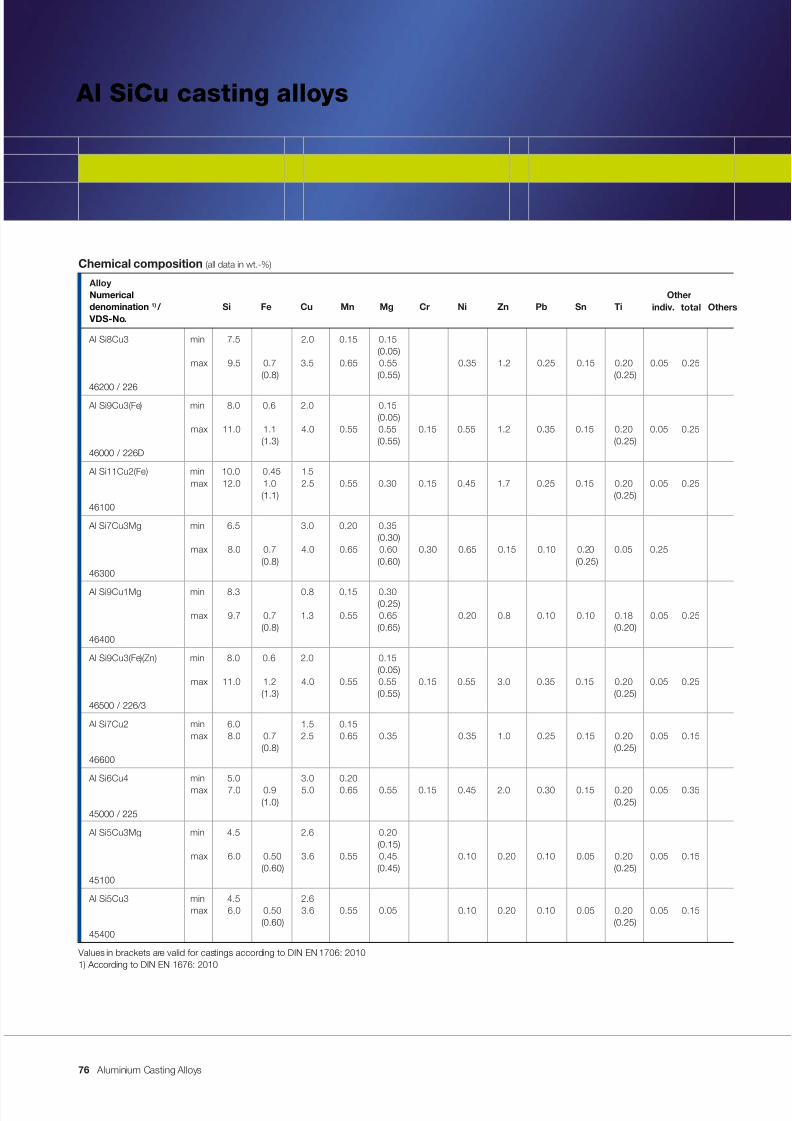
7/31/2019 Aluminium Casting Alloys EnglishVersion 2011
http://slidepdf.com/reader/full/aluminium-casting-alloys-englishversion-2011 76/102
Aluminium Casting Alloys
Al SiCu casting alloys
Chemical composition (all data in wt.-%)
AlloyNumerical Other
denomination 1) / Si Fe Cu Mn Mg Cr Ni Zn Pb Sn Ti VDS-No.
Al Si8Cu3 min 7.5 2.0 0.15 0.15 (0.05)
max 9.5 0.7 3.5 0.65 0.55 0.35 1.2 0.25 0.15 0.20 0.05 0.25 (0.8) (0.55) (0.25)
46200 / 226
Al Si9Cu3(Fe) min 8.0 0.6 2.0 0.15 (0.05)
max 11.0 1.1 4.0 0.55 0.55 0.15 0.55 1.2 0.35 0.15 0.20 0.05 0.25(1.3) (0.55) (0.25)
46000 / 226D
Al Si11Cu2(Fe) min 10.0 0.45 1.5max 12.0 1.0 2.5 0.55 0.30 0.15 0.45 1.7 0.25 0.15 0.20 0.05 0.25
(1.1) (0.25)46100
Al Si7Cu3Mg min 6.5 3.0 0.20 0.35 (0.30)
max 8.0 0.7 4.0 0.65 0.60 0.30 0.65 0.15 0.10 0.20 0.05 0.25(0.8) (0.60) (0.25)
46300
Al Si9Cu1Mg min 8.3 0.8 0.15 0.30 (0.25)
max 9.7 0.7 1.3 0.55 0.65 0.20 0.8 0.10 0.10 0.18 0.05 0.25 (0.8) (0.65) (0.20)
46400
Al Si9Cu3(Fe)(Zn) min 8.0 0.6 2.0 0.15 (0.05)
max 11.0 1.2 4.0 0.55 0.55 0.15 0.55 3.0 0.35 0.15 0.20 0.05 0.25 (1.3) (0.55) (0.25)
46500 / 226/3
Al Si7Cu2 min 6.0 1.5 0.15max 8.0 0.7 2.5 0.65 0.35 0.35 1.0 0.25 0.15 0.20 0.05 0.15
(0.8) (0.25)46600
Al Si6Cu4 min 5.0 3.0 0.20max 7.0 0.9 5.0 0.65 0.55 0.15 0.45 2.0 0.30 0.15 0.20 0.05 0.35
(1.0) (0.25)45000 / 225
Al Si5Cu3Mg min 4.5 2.6 0.20 (0.15)
max 6.0 0.50 3.6 0.55 0.45 0.10 0.20 0.10 0.05 0.20 0.05 0.15(0.60) (0.45) (0.25)
45100
Al Si5Cu3 min 4.5 2.6max 6.0 0.50 3.6 0.55 0.05 0.10 0.20 0.10 0.05 0.20 0.05 0.15
(0.60) (0.25)45400
Values in brackets are valid for castings according to DIN EN 1706: 20101) According to DIN EN 1676: 2010
Otherstotalindiv.
76
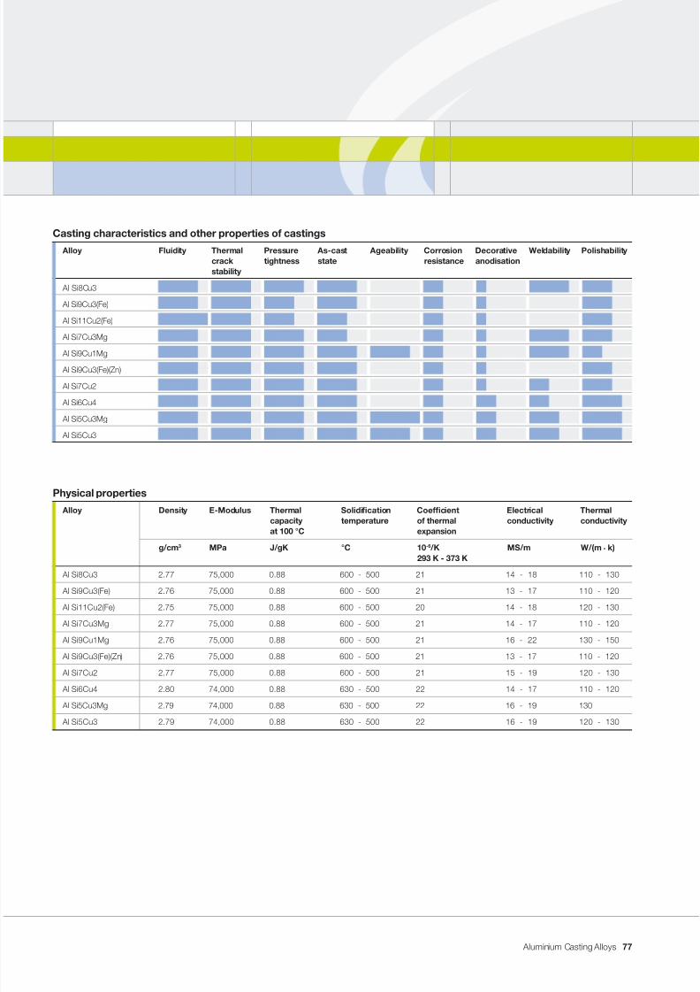
7/31/2019 Aluminium Casting Alloys EnglishVersion 2011
http://slidepdf.com/reader/full/aluminium-casting-alloys-englishversion-2011 77/102
Aluminium Casting Alloys
Casting characteristics and other properties of castings
Alloy Fluidity Thermal Pressure As-cast Ageability Corrosion Decorative Weldability Polishabilitycrack tightness state resistance anodisationstability
Al Si8Cu3
Al Si9Cu3(Fe)
Al Si11Cu2(Fe)
Al Si7Cu3Mg
Al Si9Cu1Mg
Al Si9Cu3(Fe)(Zn)
Al Si7Cu2
Al Si6Cu4
Al Si5Cu3Mg
Al Si5Cu3
Physical properties
Alloy Density E-Modulus Thermal Solidication Coefcient Electrical Thermal
capacity temperature of thermal conductivity conductivityat 100 °C expansion
g/cm 3 MPa J/gK °C 10 -6 /K MS/m W/(m . k)293 K - 373 K
Al Si8Cu3 2.77 75,000 0.88 600 - 500 21 14 - 18 110 - 130
Al Si9Cu3(Fe) 2.76 75,000 0.88 600 - 500 21 13 - 17 110 - 120
Al Si11Cu2(Fe) 2.75 75,000 0.88 600 - 500 20 14 - 18 120 - 130
Al Si7Cu3Mg 2.77 75,000 0.88 600 - 500 21 14 - 17 110 - 120
Al Si9Cu1Mg 2.76 75,000 0.88 600 - 500 21 16 - 22 130 - 150
Al Si9Cu3(Fe)(Zn) 2.76 75,000 0.88 600 - 500 21 13 - 17 110 - 120
Al Si7Cu2 2.77 75,000 0.88 600 - 500 21 15 - 19 120 - 130
Al Si6Cu4 2.80 74,000 0.88 630 - 500 22 14 - 17 110 - 120
Al Si5Cu3Mg 2.79 74,000 0.88 630 - 500 22 16 - 19 130
Al Si5Cu3 2.79 74,000 0.88 630 - 500 22 16 - 19 120 - 130
77
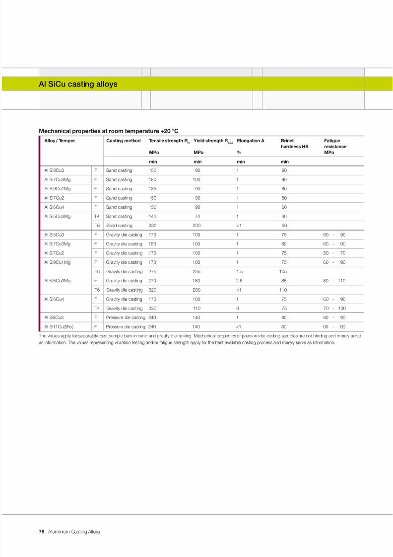
7/31/2019 Aluminium Casting Alloys EnglishVersion 2011
http://slidepdf.com/reader/full/aluminium-casting-alloys-englishversion-2011 78/102
Aluminium Casting Alloys
Al SiCu casting alloys
Mechanical properties at room temperature +20 °C
Alloy / Temper Casting method Tensile strength R m Yield strength R p0,2 Elongation A Brinell Fatiguehardness HB resistance
MPa MPa % MPa
min min min min
Al Si8Cu3 F Sand casting 150 90 1 60
Al Si7Cu3Mg F Sand casting 180 100 1 80
Al Si9Cu1Mg F Sand casting 135 90 1 60
Al Si7Cu2 F Sand casting 150 90 1 60
Al Si6Cu4 F Sand casting 150 90 1 60
Al Si5Cu3Mg T4 Sand casting 140 70 1 60
T6 Sand casting 230 200 <1 90
Al Si5Cu3 F Gravity die casting 170 100 1 75 60 - 90
Al Si7Cu3Mg F Gravity die casting 180 100 1 80 60 - 90
Al Si7Cu2 F Gravity die casting 170 100 1 75 50 - 70
Al Si9Cu1Mg F Gravity die casting 170 100 1 75 60 - 90
T6 Gravity die casting 275 235 1.5 105
Al Si5Cu3Mg F Gravity die casting 270 180 2.5 85 80 - 110
T6 Gravity die casting 320 280 <1 110
Al Si6Cu4 F Gravity die casting 170 100 1 75 60 - 90
T4 Gravity die casting 230 110 6 75 70 - 100
Al Si8Cu3 F Pressure die casting 240 140 1 80 60 - 90
Al Si11Cu2(Fe) F Pressure die casting 240 140 <1 80 60 - 90
The values apply for separately-cast sample bars in sand and gravity die casting. Mechanical properties of pressure die casting samples are not binding and merely serveas information. The values representing vibration testing and/or fatigue strength apply for the best available casting process and merely serve as information.
78
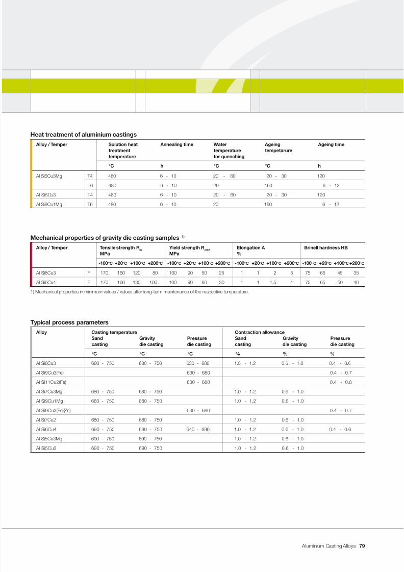
7/31/2019 Aluminium Casting Alloys EnglishVersion 2011
http://slidepdf.com/reader/full/aluminium-casting-alloys-englishversion-2011 79/102
Aluminium Casting Alloys
Mechanical properties of gravity die casting samples 1)
Alloy / Temper Tensile strength R m Yield strength R p0,2 Elongation A Brinell hardness HBMPa MPa %
-100 °C +20 °C +100 °C +200 °C -100 °C +20 °C +100 °C +200 °C -100 °C +20 °C +100 °C +200 °C -100 °C +20 °C +100 °C +200 °C
Al Si8Cu3 F 170 160 120 80 100 90 50 25 1 1 2 5 75 65 45 35
Al Si6Cu4 F 170 160 130 100 100 90 60 30 1 1 1.5 4 75 65 50 40
1) Mechanical properties in minimum values / values after long-term maintenance of the respective temperature.
Typical process parameters
Alloy Casting temperature Contraction allowanceSand Gravity Pressure Sand Gravity Pressurecasting die casting die casting casting die casting die casting
°C °C °C % % %
Al Si8Cu3 680 - 750 680 - 750 630 - 680 1.0 - 1.2 0.6 - 1.0 0.4 - 0.6
Al Si9Cu3(Fe) 630 - 680 0.4 - 0.7
Al Si11Cu2(Fe) 630 - 680 0.4 - 0.8
Al Si7Cu3Mg 680 - 750 680 - 750 1.0 - 1.2 0.6 - 1.0
Al Si9Cu1Mg 680 - 750 680 - 750 1.0 - 1.2 0.6 - 1.0
Al Si9Cu3(Fe)(Zn) 630 - 680 0.4 - 0.7
Al Si7Cu2 680 - 750 680 - 750 1.0 - 1.2 0.6 - 1.0
Al Si6Cu4 690 - 750 690 - 750 640 - 690 1.0 - 1.2 0.6 - 1.0 0.4 - 0.6
Al Si5Cu3Mg 690 - 750 690 - 750 1.0 - 1.2 0.6 - 1.0
Al Si5Cu3 690 - 750 690 - 750 1.0 - 1.2 0.6 - 1.0
Heat treatment of aluminium castings
Alloy / Temper Solution heat Annealing time Water Ageing Ageing timetreatment temperature tempetaruretemperature for quenching
°C h °C °C h
Al Si5Cu3Mg T4 480 6 - 10 20 - 60 20 - 30 120
T6 480 6 - 10 20 160 6 - 12
Al Si5Cu3 T4 480 6 - 10 20 - 60 20 - 30 120
Al Si9Cu1Mg T6 480 6 - 10 20 160 6 - 12
79
7/31/2019 Aluminium Casting Alloys EnglishVersion 2011
http://slidepdf.com/reader/full/aluminium-casting-alloys-englishversion-2011 80/102
Aluminium Casting Alloys
Application notes
The alloys in this group are among the
most commonly used aluminium cast-
ing alloys around. They are regarded
as universal casting alloys for the most
important casting processes and are
widely used in pressure die casting inparticular. They are easily cast and are
suitable for parts which are subjected
to relatively high loads. They are heat
resistant and, as such, are used for en-
gine components and cylinder heads.
Properties and processing
Aluminium casting alloys with approx. 6
to 8 % silicon, 3 to 4 % copper as well
as 0.3 to 0.5 % magnesium have the
optimum high-temperature strength.
The cast structure hardens on its own
within a week of casting. Afterwards, themechanical machinability of the casting
is very good. Age hardening is some-
times possible. Treatment of the melt:
In sand castings or thick-walled grav-
ity die castings, sodium modication is
possible. Often, grain renement is also
carried out. The casting and solidica-
tion behaviour usually poses no problem.
The type of solidication is hypoeutec-
tic. During the transition from liquid to
solid state, there is a wide solidication
range of a pasty-mushy character. At-
tention must be paid to controlling the
solidication and feeding of the metal.
There is no distinctive tendency to hot
cracking or draws.
Heat treatment
With castings made from these casting
alloys, age hardening is possible when
the Cu and Mg content is appropriate. It
is, however, seldom carried out. In these
castings, due to the Cu content in con-
nection with the Mg and Zn content, anindependent structural hardening occurs.
This process is complete within about a
week. Only then should the castings be
nished followed by checking the me-
chanical properties. To achieve thermal
and dimensional stability in parts suit-
able for high-pressure applications, e.g.
crankcases, cylinder heads or pistons,
solution annealing with articial ageing
beyond the peak aged condition is sug-
gested (T7). This process is also known
as “stabilising” or “overageing”.
Al SiCu casting alloys
80
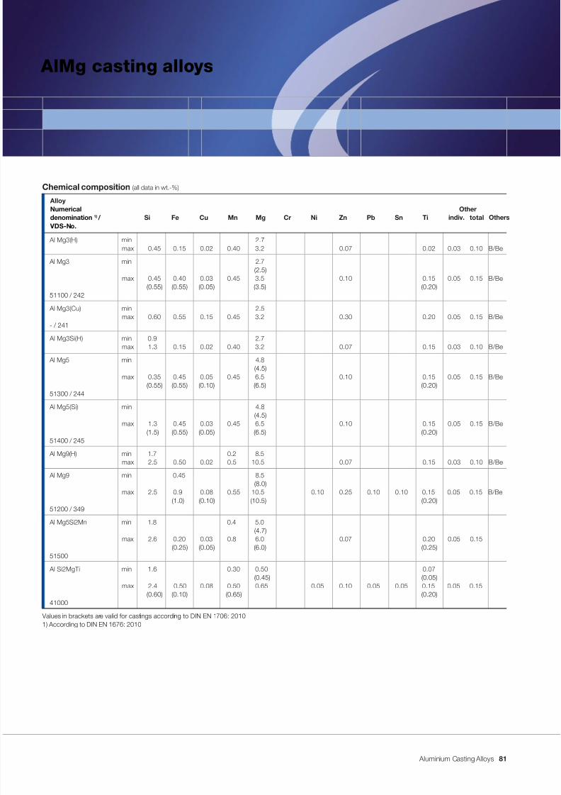
7/31/2019 Aluminium Casting Alloys EnglishVersion 2011
http://slidepdf.com/reader/full/aluminium-casting-alloys-englishversion-2011 81/102
Aluminium Casting Alloys
AlMg casting alloys
Chemical composition (all data in wt.-%)
AlloyNumerical Other
denomination 1) / Si Fe Cu Mn Mg Cr Ni Zn Pb Sn Ti VDS-No.
Al Mg3(H) min 2.7max 0.45 0.15 0.02 0.40 3.2 0.07 0.02 0.03 0.10 B/Be
Al Mg3 min 2.7 (2.5)
max 0.45 0.40 0.03 0.45 3.5 0.10 0.15 0.05 0.15 B/Be (0.55) (0.55) (0.05) (3.5) (0.20)
51100 / 242
Al Mg3(Cu) min 2.5max 0.60 0.55 0.15 0.45 3.2 0.30 0.20 0.05 0.15 B/Be
- / 241
Al Mg3Si(H) min 0.9 2.7max 1.3 0.15 0.02 0.40 3.2 0.07 0.15 0.03 0.10 B/Be
Al Mg5 min 4.8 (4.5)
max 0.35 0.45 0.05 0.45 6.5 0.10 0.15 0.05 0.15 B/Be (0.55) (0.55) (0.10) (6.5) (0.20)
51300 / 244
Al Mg5(Si) min 4.8
(4.5)max 1.3 0.45 0.03 0.45 6.5 0.10 0.15 0.05 0.15 B/Be (1.5) (0.55) (0.05) (6.5) (0.20)
51400 / 245
Al Mg9(H) min 1.7 0.2 8.5max 2.5 0.50 0.02 0.5 10.5 0.07 0.15 0.03 0.10 B/Be
Al Mg9 min 0.45 8.5 (8.0)
max 2.5 0.9 0.08 0.55 10.5 0.10 0.25 0.10 0.10 0.15 0.05 0.15 B/Be(1.0) (0.10) (10.5) (0.20)
51200 / 349
Al Mg5Si2Mn min 1.8 0.4 5.0 (4.7)
max 2.6 0.20 0.03 0.8 6.0 0.07 0.20 0.05 0.15(0.25) (0.05) (6.0) (0.25)
51500 Al Si2MgTi min 1.6 0.30 0.50 0.07
(0.45) (0.05)max 2.4 0.50 0.08 0.50 0.65 0.05 0.10 0.05 0.05 0.15 0.05 0.15
(0.60) (0.10) (0.65) (0.20)41000
Values in brackets are valid for castings according to DIN EN 1706: 20101) According to DIN EN 1676: 2010
Otherstotalindiv.
81
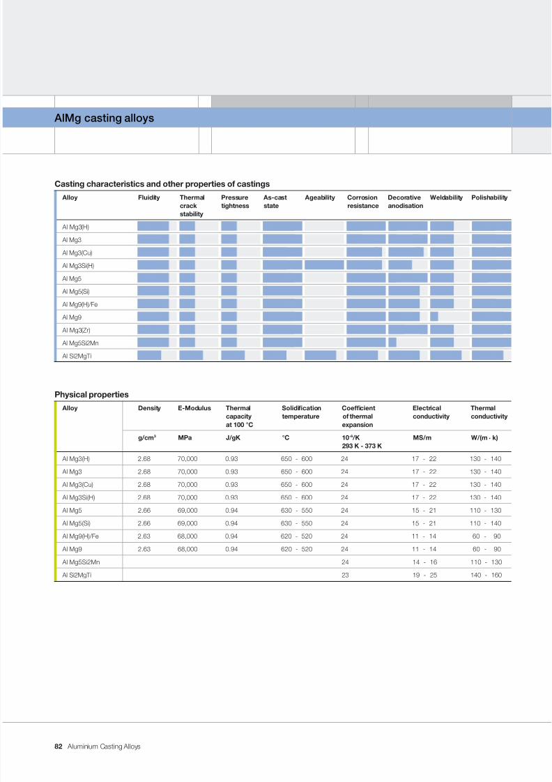
7/31/2019 Aluminium Casting Alloys EnglishVersion 2011
http://slidepdf.com/reader/full/aluminium-casting-alloys-englishversion-2011 82/102
Aluminium Casting Alloys
AlMg casting alloys
Physical properties
Alloy Density E-Modulus Thermal Solidication Coefcient Electrical Thermalcapacity temperature of thermal conductivity conductivityat 100 °C expansion
g/cm 3 MPa J/gK °C 10 -6 /K MS/m W/(m . k)293 K - 373 K
Al Mg3(H) 2.68 70,000 0.93 650 - 600 24 17 - 22 130 - 140
Al Mg3 2.68 70,000 0.93 650 - 600 24 17 - 22 130 - 140
Al Mg3(Cu) 2.68 70,000 0.93 650 - 600 24 17 - 22 130 - 140
Al Mg3Si(H) 2.68 70,000 0.93 650 - 600 24 17 - 22 130 - 140
Al Mg5 2.66 69,000 0.94 630 - 550 24 15 - 21 110 - 130
Al Mg5(Si) 2.66 69,000 0.94 630 - 550 24 15 - 21 110 - 140
Al Mg9(H)/Fe 2.63 68,000 0.94 620 - 520 24 11 - 14 60 - 90
Al Mg9 2.63 68,000 0.94 620 - 520 24 11 - 14 60 - 90
Al Mg5Si2Mn 24 14 - 16 110 - 130
Al Si2MgTi 23 19 - 25 140 - 160
Casting characteristics and other properties of castings
Alloy Fluidity Thermal Pressure As-cast Ageability Corrosion Decorative Weldability Polishabilitycrack tightness state resistance anodisationstability
Al Mg3(H)
Al Mg3
Al Mg3(Cu)
Al Mg3Si(H)
Al Mg5
Al Mg5(Si)
Al Mg9(H)/Fe
Al Mg9
Al Mg3(Zr)
Al Mg5Si2Mn
Al Si2MgTi
82
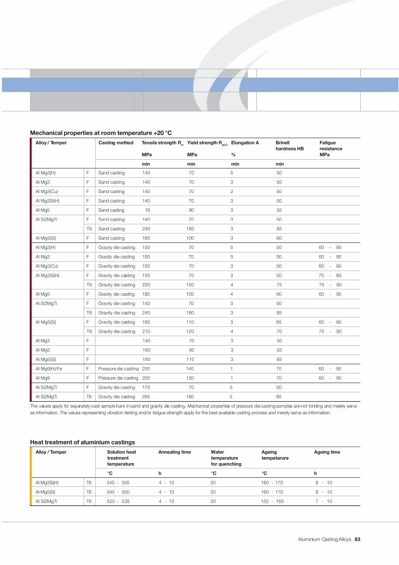
7/31/2019 Aluminium Casting Alloys EnglishVersion 2011
http://slidepdf.com/reader/full/aluminium-casting-alloys-englishversion-2011 83/102
Aluminium Casting Alloys
Mechanical properties at room temperature +20 °C
Alloy / Temper Casting method Tensile strength R m Yield strength R p0,2 Elongation A Brinell Fatiguehardness HB resistance
MPa MPa % MPa
min min min min
Al Mg3(H) F Sand casting 140 70 5 50
Al Mg3 F Sand casting 140 70 3 50
Al Mg3(Cu) F Sand casting 140 70 2 50
Al Mg3Si(H) F Sand casting 140 70 3 50
Al Mg5 F Sand casting 16 90 3 55
Al Si2MgTi F Sand casting 140 70 3 50
T6 Sand casting 240 180 3 85
Al Mg5(Si) F Sand casting 160 100 3 60
Al Mg3(H) F Gravity die casting 150 70 5 50 60 - 90
Al Mg3 F Gravity die casting 150 70 5 50 60 - 90
Al Mg3(Cu) F Gravity die casting 150 70 3 50 60 - 90
Al Mg3Si(H) F Gravity die casting 150 70 3 50 70 - 80
T6 Gravity die casting 220 150 4 75 70 - 90
Al Mg5 F Gravity die casting 180 100 4 60 60 - 90
Al Si2MgTi F Gravity die casting 140 70 3 50
T6 Gravity die casting 240 180 3 85
Al Mg5(Si) F Gravity die casting 180 110 3 65 60 - 90
T6 Gravity die casting 210 120 4 70 70 - 90
Al Mg3 F 140 70 3 50
Al Mg5 F 160 90 3 55
Al Mg5(Si) F 180 110 3 65
Al Mg9(H)/Fe F Pressure die casting 200 140 1 70 60 - 90
Al Mg9 F Pressure die casting 200 130 1 70 60 - 90
Al Si2MgTi F Gravity die casting 170 70 5 50
Al Si2MgTi T6 Gravity die casting 260 180 5 85
The values apply for separately-cast sample bars in sand and gravity die casting. Mechanical properties of pressure die casting samples are not binding and merely serveas information. The values representing vibration testing and/or fatigue strength apply for the best available casting process and merely serve as information.
Heat treatment of aluminium castings
Alloy / Temper Solution heat Annealing time Water Ageing Ageing timetreatment temperature tempetaruretemperature for quenching
°C h °C °C h
Al Mg3Si(H) T6 545 - 555 4 - 10 20 160 - 170 8 - 10
Al Mg5(Si) T6 540 - 550 4 - 10 20 160 - 170 8 - 10
Al Si2MgTi T6 520 - 535 4 - 10 20 155 - 165 7 - 10
83
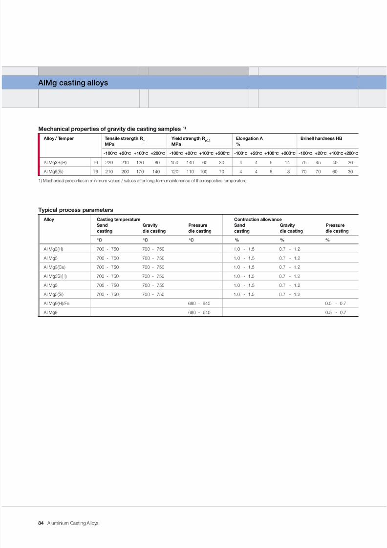
7/31/2019 Aluminium Casting Alloys EnglishVersion 2011
http://slidepdf.com/reader/full/aluminium-casting-alloys-englishversion-2011 84/102
Aluminium Casting Alloys
AlMg casting alloys
Mechanical properties of gravity die casting samples 1)
Alloy / Temper Tensile strength R m Yield strength R p0,2 Elongation A Brinell hardness HBMPa MPa %
-100 °C +20 °C +100 °C +200 °C -100 °C +20 °C +100 °C +200 °C -100 °C +20 °C +100 °C +200 °C -100 °C +20 °C +100 °C +200 °C
Al Mg3Si(H) T6 220 210 120 80 150 140 60 30 4 4 5 14 75 45 40 20
Al Mg5(Si) T6 210 200 170 140 120 110 100 70 4 4 5 8 70 70 60 30
1) Mechanical properties in minimum values / values after long-term maintenance of the respective temperature.
Typical process parameters
Alloy Casting temperature Contraction allowanceSand Gravity Pressure Sand Gravity Pressurecasting die casting die casting casting die casting die casting
°C °C °C % % %
Al Mg3(H) 700 - 750 700 - 750 1.0 - 1.5 0.7 - 1.2
Al Mg3 700 - 750 700 - 750 1.0 - 1.5 0.7 - 1.2
Al Mg3(Cu) 700 - 750 700 - 750 1.0 - 1.5 0.7 - 1.2
Al Mg3Si(H) 700 - 750 700 - 750 1.0 - 1.5 0.7 - 1.2
Al Mg5 700 - 750 700 - 750 1.0 - 1.5 0.7 - 1.2
Al Mg5(Si) 700 - 750 700 - 750 1.0 - 1.5 0.7 - 1.2
Al Mg9(H)/Fe 680 - 640 0.5 - 0.7
Al Mg9 680 - 640 0.5 - 0.7
84
7/31/2019 Aluminium Casting Alloys EnglishVersion 2011
http://slidepdf.com/reader/full/aluminium-casting-alloys-englishversion-2011 85/102
Aluminium Casting Alloys
Application notes
We produce Al Mg3-type casting alloys
for handles, window handles or security
covers in decorative anodised quality.
For structures in the chemical industry, in
shipbuilding or the food industry, which
demand the highest possible resistanceto chemical attack and the inuences of
maritime climates, Al Mg5-type cast-
ing alloys are suitable. Heat-resistant
Al Mg5Si-type casting alloys are suit-
able for high-temperature applications
such as engine construction. In France,
the Al Si2MgTi alloy is used for handles.
For pressure die castings with good cor-
rosion resistance, Al Mg9-type casting
alloys are used.
Properties and processing
The highest requirements are placed on
the quality of these casting alloys – par-
ticularly for decorative parts which are
anodised. The manufacture of these cast-
ing alloys represents a special challenge
for smelters requiring much experience,the best raw materials and quality-ori-
ented work.
Notes about surface treatment
As a pre-treatment, the surfaces of cast-
ings made from Al Mg3, for example, are
mechanically machined as well as often
being chemically polished. In the anodis-
ing process (electrolytically-oxidised alu-
minium), a protective oxide layer, whichgrows inwards and is essentially more
impervious, thicker, more wear resistant
and more homogeneous than a natural
oxide skin, is produced on the surface
of a casting. On pure aluminium and on
aluminium alloys which are low in pre-
cipitates, these layers are transparent.
All defects such as precipitated inter-
metallic phases, inclusions, heteroge-
neities, oxide lms, wrinkles and other
casting defects lead to disturbances in
the growth of the layer formation and,
consequently, impairment of the deco-
rative appearance.
As the electro-chemically formed oxide
layer is also the possible carrier of dis-
colouring substances, defects near the
surface can lead to the parts having a
blemished, non-decorative appearance.
Hollow spaces such as wrinkles or poreswhich have been cut can be taken up
by the aqueous solutions or electrolyte
during treatment. Even later, due to a
secondary reaction, the remainder of this
medium can lead to local decomposi-
tion of the anodised or colour coating.
85
7/31/2019 Aluminium Casting Alloys EnglishVersion 2011
http://slidepdf.com/reader/full/aluminium-casting-alloys-englishversion-2011 86/102
Aluminium Casting Alloys
AlMg casting alloys
The following alloying constituents can
have an inuence on the quality and ap-
pearance of anodised layers:
Silicon
With Si concentrations higher than
0.6 %, the precipitated silicon or Mg2Si
impairs transparency. The anodised layerloses its brilliance.
Iron, chromium and manganese
The sum total of these elements can
have a yellowing effect on the anodised
layer. Limiting concentrations can not
be established. Their inuence depends
on the phase composition and chemi-
cal back-dissolution during anodising.
Copper
It has no negative inuence when found
in normal concentrations. In the case of
higher additions, the layer becomes softer
and the composition rougher.
Zinc
This element has no inuence on the
anodising process or pigmentation.
TitaniumConcentrations of Ti above 0.02 % have
a negative effect on the electrolytic col-
ouration of aluminium castings.
Notes on casting techniques
To avoid the tendency to hot tearing
during casting and particularly for deco-
rative reasons, the cast structure must
be ne-grained. This ne-grained struc-
ture can already be achieved during the
production of the ingots by means ofintensive grain renement. As a general
rule, this grain renement does not have
to be repeated during pouring. Should
grain renement decrease as a result
of prolonged holding, we recommend
that it be freshened up using TiB grain
rening wire. Melt cleaning or keeping
the melt clean is important in order to
produce a cast piece of good quality.
We recommend that only those ren-
ing uxes which are specically suited
to AlMg casting alloys be used.
Bale-out vessels with ceramic lter ele-
ments have also proven their worth. Dur-
ing casting, only the ltrate is baled out;
the ladle remainder and subsequently
charged metal enter into the outside
areas of the melting or holding crucible.
The casting operation requires particular
care in order to produce a sound cast-ing despite the constant risk of forming
oxides and shrinkage. In doing this, the
conguration of the dies and the cast-
ing system play an important role. The
type of solidication is globular-mushy.
A good feeding system is an essen-
tial prerequisite for producing a dense
structure.
86
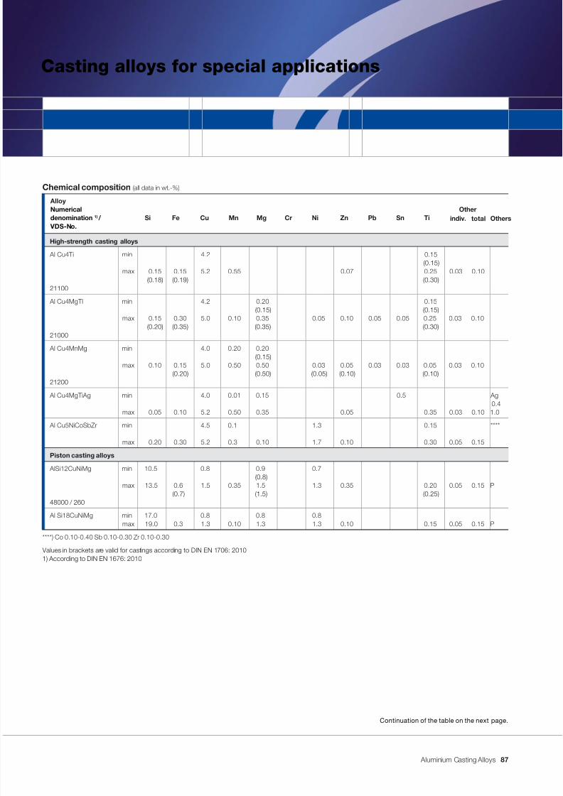
7/31/2019 Aluminium Casting Alloys EnglishVersion 2011
http://slidepdf.com/reader/full/aluminium-casting-alloys-englishversion-2011 87/102
Aluminium Casting Alloys
Casting alloys for special applications
Continuation of the table on the next page.
Chemical composition (all data in wt.-%)
AlloyNumerical Other
denomination 1) / Si Fe Cu Mn Mg Cr Ni Zn Pb Sn Ti VDS-No.
Otherstotalindiv.
High-strength casting alloys
Al Cu4Ti min 4.2 0.15 (0.15)
max 0.15 0.15 5.2 0.55 0.07 0.25 0.03 0.10
(0.18) (0.19) (0.30)21100
Al Cu4MgTI min 4.2 0.20 0.15 (0.15) (0.15)
max 0.15 0.30 5.0 0.10 0.35 0.05 0.10 0.05 0.05 0.25 0.03 0.10 (0.20) (0.35) (0.35) (0.30)
21000
Al Cu4MnMg min 4.0 0.20 0.20 (0.15)
max 0.10 0.15 5.0 0.50 0.50 0.03 0.05 0.03 0.03 0.05 0.03 0.10(0.20) (0.50) (0.05) (0.10) (0.10)
21200
Al Cu4MgTiAg min 4.0 0.01 0.15 0.5 Ag0.4
max 0.05 0.10 5.2 0.50 0.35 0.05 0.35 0.03 0.10 1.0
Al Cu5NiCoSbZr min 4.5 0.1 1.3 0.15 ****
max 0.20 0.30 5.2 0.3 0.10 1.7 0.10 0.30 0.05 0.15
Piston casting alloys
AlSi12CuNiMg min 10.5 0.8 0.9 0.7 (0.8)
max 13.5 0.6 1.5 0.35 1.5 1.3 0.35 0.20 0.05 0.15 P(0.7) (1.5) (0.25)
48000 / 260
Al Si18CuNiMg min 17.0 0.8 0.8 0.8max 19.0 0.3 1.3 0.10 1.3 1.3 0.10 0.15 0.05 0.15 P
****) Co 0.10-0.40 Sb 0.10-0.30 Zr 0.10-0.30
Values in brackets are valid for castings according to DIN EN 1706: 2010
1) According to DIN EN 1676: 2010
87
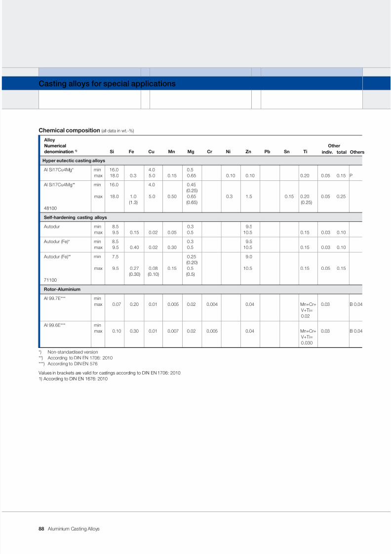
7/31/2019 Aluminium Casting Alloys EnglishVersion 2011
http://slidepdf.com/reader/full/aluminium-casting-alloys-englishversion-2011 88/102
Aluminium Casting Alloys
Casting alloys for special applications
Chemical composition (all data in wt.-%)
AlloyNumerical Other
denomination 1) Si Fe Cu Mn Mg Cr Ni Zn Pb Sn Ti
Hyper eutectic casting alloys
Al Si17Cu4Mg* min 16.0 4.0 0.5max 18.0 0.3 5.0 0.15 0.65 0.10 0.10 0.20 0.05 0.15 P
Al Si17Cu4Mg** min 16.0 4.0 0.45 (0.25)
max 18.0 1.0 5.0 0.50 0.65 0.3 1.5 0.15 0.20 0.05 0.25 (1.3) (0.65) (0.25)
48100
Self-hardening casting alloys
Autodur min 8.5 0.3 9.5max 9.5 0.15 0.02 0.05 0.5 10.5 0.15 0.03 0.10
Autodur (Fe)* min 8.5 0.3 9.5max 9.5 0.40 0.02 0.30 0.5 10.5 0.15 0.03 0.10
Autodur (Fe)** min 7.5 0.25 9.0 (0.20)
max 9.5 0.27 0.08 0.15 0.5 10.5 0.15 0.05 0.15 (0.30) (0.10) (0.5)
71100
Rotor-Aluminium Al 99.7E*** min
max 0.07 0.20 0.01 0.005 0.02 0.004 0.04 Mn+Cr+ 0.03 B 0.04V+ Ti=0.02
Al 99.6E*** minmax 0.10 0.30 0.01 0.007 0.02 0.005 0.04 Mn+Cr+ 0.03 B 0.04
V+Ti=0.030
*) Non-standardised version**) According to DIN EN 1706: 2010***) According to DIN EN 576
Values in brackets are valid for castings according to DIN EN 1706: 20101) According to DIN EN 1676: 2010
Otherstotalindiv.
88
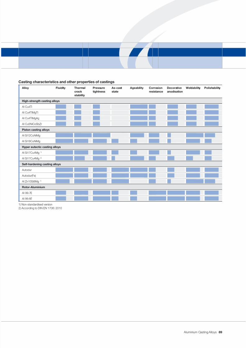
7/31/2019 Aluminium Casting Alloys EnglishVersion 2011
http://slidepdf.com/reader/full/aluminium-casting-alloys-englishversion-2011 89/102
Aluminium Casting Alloys
Casting characteristics and other properties of castings
Alloy Fluidity Thermal Pressure As-cast Ageability Corrosion Decorative Weldability Polishabilitycrack tightness state resistance anodisationstability
High-strength casting alloys
Al Cu4Ti
Al Cu4TiMgTi
Al Cu4TiMgAg
Al Cu5NiCoSbZr
Piston casting alloys
Al Si12CuNiMg
Al Si18CuNiMg
Hyper eutectic casting alloys
Al Si17Cu4Mg 1)
Al Si17Cu4Mg 2)
Self-hardening casting alloys
Autodur
Autodur(Fe)
Al Zn10Si8Mg1)
Rotor-Aluminium
Al 99.7E
Al 99.6E
1) Non-standardised version2) According to DIN EN 1706: 2010
89
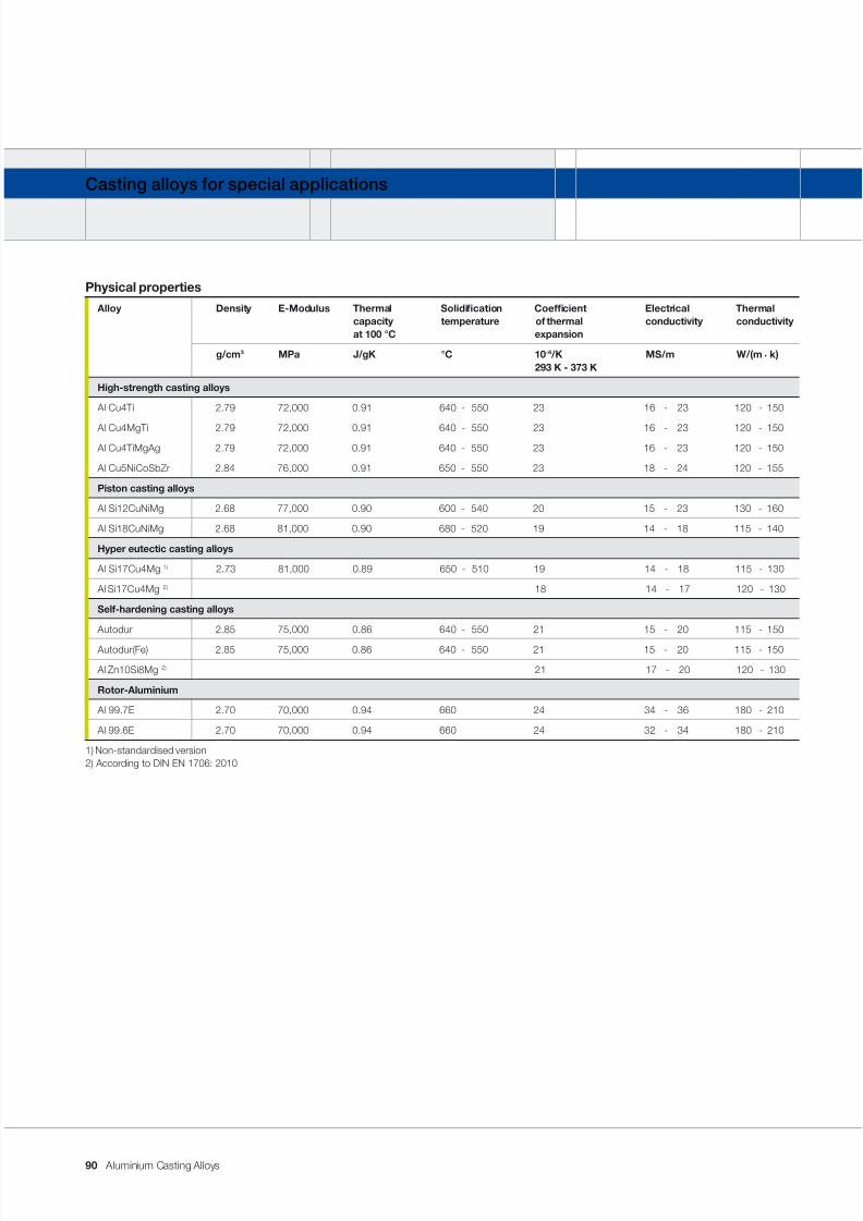
7/31/2019 Aluminium Casting Alloys EnglishVersion 2011
http://slidepdf.com/reader/full/aluminium-casting-alloys-englishversion-2011 90/102
Aluminium Casting Alloys
Casting alloys for special applications
Physical properties
Alloy Density E-Modulus Thermal Solidication Coefcient Electrical Thermalcapacity temperature of thermal conductivity conductivityat 100 °C expansion
g/cm 3 MPa J/gK °C 10 -6 /K MS/m W/(m . k)293 K - 373 K
High-strength casting alloys
Al Cu4Ti 2.79 72,000 0.91 640 - 550 23 16 - 23 120 - 150
Al Cu4MgTi 2.79 72,000 0.91 640 - 550 23 16 - 23 120 - 150
Al Cu4TiMgAg 2.79 72,000 0.91 640 - 550 23 16 - 23 120 - 150
Al Cu5NiCoSbZr 2.84 76,000 0.91 650 - 550 23 18 - 24 120 - 155
Piston casting alloys
Al Si12CuNiMg 2.68 77,000 0.90 600 - 540 20 15 - 23 130 - 160
Al Si18CuNiMg 2.68 81,000 0.90 680 - 520 19 14 - 18 115 - 140
Hyper eutectic casting alloys
Al Si17Cu4Mg 1) 2.73 81,000 0.89 650 - 510 19 14 - 18 115 - 130
Al Si17Cu4Mg 2) 18 14 - 17 120 - 130
Self-hardening casting alloys
Autodur 2.85 75,000 0.86 640 - 550 21 15 - 20 115 - 150
Autodur(Fe) 2.85 75,000 0.86 640 - 550 21 15 - 20 115 - 150
Al Zn10Si8Mg 2) 21 17 - 20 120 - 130
Rotor-Aluminium
Al 99.7E 2.70 70,000 0.94 660 24 34 - 36 180 - 210
Al 99.6E 2.70 70,000 0.94 660 24 32 - 34 180 - 210
1) Non-standardised version2) According to DIN EN 1706: 2010
90
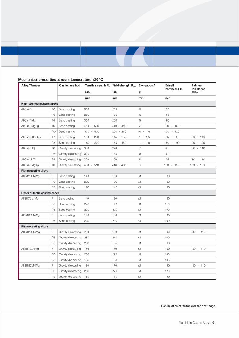
7/31/2019 Aluminium Casting Alloys EnglishVersion 2011
http://slidepdf.com/reader/full/aluminium-casting-alloys-englishversion-2011 91/102
Aluminium Casting Alloys
High-strength casting alloys
Al Cu4Ti T6 Sand casting 300 200 3 95
T64 Sand casting 280 180 5 85
Al Cu4TiMg T4 Sand casting 300 200 5 90
Al Cu4TiMgAg T6 Sand casting 460 - 510 410 - 450 7 130 - 150
T64 Sand casting 370 - 430 200 - 270 14 - 18 105 - 120
Al Cu5NiCoSbZr T7 Sand casting 180 - 220 145 - 165 1 - 1.5 85 - 95 90 - 100
T5 Sand casting 180 - 220 160 - 180 1 - 1.5 80 - 90 90 - 100
Al Cu4Ti(H) T6 Gravity die casting 330 220 7 95 80 - 110
T64 Gravity die casting 320 180 8 90
Al Cu4MgTi T4 Gravity die casting 320 200 8 95 80 - 110
Al Cu4TiMgAg T6 Gravity die casting 460 - 510 410 - 460 8 130 - 150 100 - 110
Piston casting alloys
Al Si12CuNiMg F Sand casting 140 130≤
1 80 T6 Sand casting 220 190 ≤ 1 90
T5 Sand casting 160 140 ≤ 1 80
Hyper eutectic casting alloys
Al Si17Cu4Mg F Sand casting 140 130 ≤ 1 80
T6 Sand casting 240 23 ≤ 1 110
T5 Sand casting 230 220 ≤ 1 100
Al Si18CuNiMg F Sand casting 140 130 ≤ 1 85
T6 Sand casting 230 210 ≤ 1 100
Piston casting alloys
Al Si12CuNiMg F Gravity die casting 200 190 ≤ 1 90 80 - 110
T6 Gravity die casting 280 240 ≤ 1 100
T5 Gravity die casting 200 185 ≤ 1 90
Al Si17Cu4Mg F Gravity die casting 180 170 ≤ 1 100 80 - 110
T6 Gravity die casting 280 270 ≤ 1 130
T5 Gravity die casting 165 160 ≤ 1 105
Al Si18CuNiMg F Gravity die casting 180 170 ≤ 1 90 80 - 110
T6 Gravity die casting 280 270 ≤ 1 120
T5 Gravity die casting 180 170 ≤ 1 90
Continuation of the table on the next page.
Mechanical properties at room temperature +20 °C
Alloy / Temper Casting method Tensile strength R m Yield strength R p0,2 Elongation A Brinell Fatiguehardness HB resistance
MPa MPa % MPa
min min min min
91
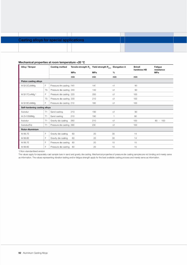
7/31/2019 Aluminium Casting Alloys EnglishVersion 2011
http://slidepdf.com/reader/full/aluminium-casting-alloys-englishversion-2011 92/102
Aluminium Casting Alloys
Casting alloys for special applications
Mechanical properties at room temperature +20 °C
Alloy / Temper Casting method Tensile strength R m Yield strength R p0,2 Elongation A Brinell Fatiguehardness HB resistance
MPa MPa % MPa
min min min min
Piston casting alloys
Al Si12CuNiMg F Pressure die casting 240 140 ≤ 1 90
T5 Pressure die casting 240 140 ≤ 1 90
Al Si17Cu4Mg 1) F Pressure die casting 220 200 ≤ 1 100
T5 Pressure die casting 230 210 ≤ 1 100
Al Si18CuNiMg F Pressure die casting 210 180 ≤ 1 100
Self-hardening casting alloys
Autodur T1 Sand casting 210 190 ≤ 1 90
Al Zn10Si8Mg T1 Sand casting 210 190 1 90
Autodur T1 Gravity die casting 260 210 ≤ 1 100 80 - 100
Autodur(Fe) T1 Pressure die casting 290 230 ≤ 1 100
Rotor-Aluminium
Al 99.7E F Gravity die casting 60 20 30 14
Al 99.6E F Gravity die casting 60 20 30 14 Al 99.7E F Pressure die casting 80 20 10 15
Al 99.6E F Pressure die casting 80 20 10 15
1) Non-standardised version The values apply for separately-cast sample bars in sand and gravity die casting. Mechanical properties of pressure die casting samples are not binding and merely serveas information. The values representing vibration testing and/or fatigue strength apply for the best available casting process and merely serve as information.
92
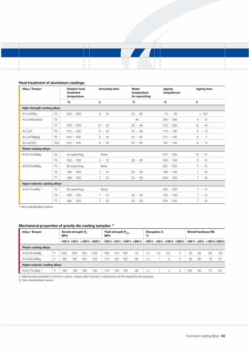
7/31/2019 Aluminium Casting Alloys EnglishVersion 2011
http://slidepdf.com/reader/full/aluminium-casting-alloys-englishversion-2011 93/102
Aluminium Casting Alloys
Heat treatment of aluminium castings
Alloy / Temper Solution heat Annealing time Water Ageing Ageing timetreatment temperature tempetaruretemperature for quenching
°C h °C °C h
High-strength casting alloys
Al Cu4TiMg T4 520 - 530 8 - 16 20 - 80 15 - 30 > 120
Al Cu5NiCoSbZr T5 Air 345 - 355 8 - 10
T7 535 - 545 10 - 15 20 - 80 210 - 220 12 - 16
Al Cu4Ti T6 515 - 535 8 - 18 20 - 80 170 - 180 6 - 8
Al Cu4TiMgAg T6 525 - 535 8 - 18 20 - 80 170 - 180 6 - 7
Al Cu4Ti(H) T64 515 - 535 8 - 18 20 - 80 135 - 145 6 - 8
Piston casting alloys
Al Si12CuNiMg T5 Air quenching None 210 - 230 10 - 14
T6 520 - 530 5 - 10 20 - 80 165 - 185 5 - 10
Al Si18CuNiMg T5 Air quenching None 225 - 235 7 - 12
T6 495 - 505 7 - 10 20 - 80 165 - 185 7 - 10
T7 495 - 505 7 - 10 20 - 80 225 - 235 7 - 10
Hyper eutectic casting alloys Al Si17Cu4Mg 1) T5 Air quenching None 225 - 235 7 - 12
T6 495 - 505 7 - 10 20 - 80 165 - 185 7 - 10
T7 495 - 505 7 - 10 20 - 80 225 - 235 7 - 10
1) Non-standardised version
Mechanical properties of gravity die casting samples 1)
Alloy / Temper Tensile strength R m Yield strength R p0,2 Elongation A Brinell hardness HBMPa MPa %
-100 °C +20 °C +100 °C +200 °C -100 °C +20 °C +100 °C +200 °C -100 °C +20 °C +100 °C +200 °C -100 °C +20 °C +100 °C +200 °C
Piston casting alloys
Al Si12CuNiMg F 200 200 160 100 190 170 100 70 ≤ 1 1.5 2.5 3 90 85 60 35
Al Si18CuNiMg F 180 180 160 120 170 150 100 80 ≤ 1 1 2 3 90 90 70 50
Hyper eutectic casting alloys
Al Si17Cu4Mg 2) F 180 180 160 120 170 150 100 80 ≤ 1 1 2 3 100 90 70 50
1) Mechanical properties in minimum values / values after long-term maintenance of the respective temperature.2) Non-standardised version
93
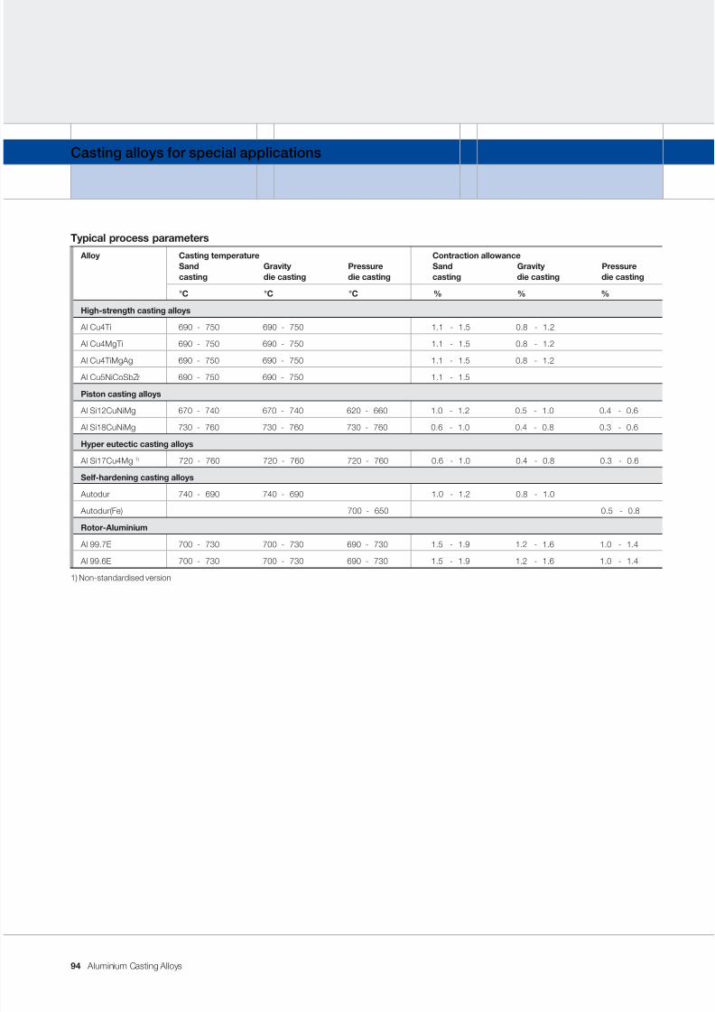
7/31/2019 Aluminium Casting Alloys EnglishVersion 2011
http://slidepdf.com/reader/full/aluminium-casting-alloys-englishversion-2011 94/102
Aluminium Casting Alloys
Casting alloys for special applications
Typical process parameters
Alloy Casting temperature Contraction allowanceSand Gravity Pressure Sand Gravity Pressurecasting die casting die casting casting die casting die casting
°C °C °C % % %
High-strength casting alloys
Al Cu4Ti 690 - 750 690 - 750 1.1 - 1.5 0.8 - 1.2
Al Cu4MgTi 690 - 750 690 - 750 1.1 - 1.5 0.8 - 1.2
Al Cu4TiMgAg 690 - 750 690 - 750 1.1 - 1.5 0.8 - 1.2
Al Cu5NiCoSbZr 690 - 750 690 - 750 1.1 - 1.5
Piston casting alloys
Al Si12CuNiMg 670 - 740 670 - 740 620 - 660 1.0 - 1.2 0.5 - 1.0 0.4 - 0.6
Al Si18CuNiMg 730 - 760 730 - 760 730 - 760 0.6 - 1.0 0.4 - 0.8 0.3 - 0.6
Hyper eutectic casting alloys
Al Si17Cu4Mg 1) 720 - 760 720 - 760 720 - 760 0.6 - 1.0 0.4 - 0.8 0.3 - 0.6
Self-hardening casting alloys
Autodur 740 - 690 740 - 690 1.0 - 1.2 0.8 - 1.0
Autodur(Fe) 700 - 650 0.5 - 0.8
Rotor-Aluminium Al 99.7E 700 - 730 700 - 730 690 - 730 1.5 - 1.9 1.2 - 1.6 1.0 - 1.4
Al 99.6E 700 - 730 700 - 730 690 - 730 1.5 - 1.9 1.2 - 1.6 1.0 - 1.4
1) Non-standardised version
94
7/31/2019 Aluminium Casting Alloys EnglishVersion 2011
http://slidepdf.com/reader/full/aluminium-casting-alloys-englishversion-2011 95/102
Aluminium Casting Alloys
High-strength casting alloy
Application notes
These casting alloys are used for parts
which – compared to all other aluminium
casting alloys – require maximum strength.
Where their reduced corrosion resistance
represents no obstacles, these casting
alloys can be used to manufacture high-strength components, for example, for
the defence industry, aerospace, auto-
motive, rail vehicles, mechanical engi-
neering and the textile industry.
Properties and processing
The use of these relatively demanding
casting alloys only makes sense if the
component undergoes heat treatment.
Only then, can the potential of these
casting alloys be fully utilised. Following
heat treatment, the castings still have ex-
cellent elongation as well as displaying
the highest possible strength and hard-
ness. This combination of high strength
and good elongation values gives these
casting alloys the highest possible Qual-
ity Index “Q”.
By means of special heat treatment,
hardness and elongation values can be
adjusted within determined limits. There
are other variants of these aluminium
casting alloys, e.g. with nickel and cobalt
being added to optimise their strength.
Furthermore, there are also casting al-
loy types which contain silver so as to
meet the maximum strength require-
ments. The corrosion resistance of cast
pieces is reduced, however, due to the
high copper content.
The casting technique for these alloys is
demanding. Most defects in the castings
stem from “contamination” with silicon.
The silicon content should be kept as
low as possible and always lower than
the iron content. An excess of silicon
produces a low melting phase and in-
creases the susceptibility to hot tearing
during solidication. Even slight impedi-
ments to solidication shrinkage can
lead to structural separation. The most
important requirement in the foundry is
therefore cleanliness to prevent the take-
up of silicon. Here are some recommen-
dations: The melting crucible must not
contain any remainder of silicon alloys.
It also makes good sense to melt several
batches of an alloy which is low in sili-
con in a new crucible to free the crucible
material of silicon. There are users who,
for this reason, use melting cruciblesmade of graphite or cast iron for these
casting alloys. Return material should
also be checked very strictly and stored
separately; residual sand and other return
material must be painstakingly removed
from all sprues. From practical experi-
ence, some users recommend having a
separate foundry department for these
casting alloys. Melt cleaning and degas-
sing can be carried out without any trou-
ble using normal means. Melt treatment
is restricted to grain renement which,
among other things, slightly counteractsthe susceptibility to hot cracking. Inten-
sive grain renement is already performed
by us so it does not usually need to be
repeated in the foundry. The uidity of
these casting alloys is comparable with
other hypoeutectic AlSi casting alloys.
The solidication characteristics are best
described as being globular-mushy. At
approx. 90 K, the solidication range is
relatively high. Using a good lling system
in conjunction with steered or controlled
solidication and suitable feeding, opti-
mum structural qualities can be achieved
with the sand and gravity die casting
processes. Thanks to their good struc-
tural quality and optimum heat treatment,
these high-strength casting alloys are
suitable for the manufacture of castings
whose unmatched mechanical proper-
ties comply with maximum demands.
95
7/31/2019 Aluminium Casting Alloys EnglishVersion 2011
http://slidepdf.com/reader/full/aluminium-casting-alloys-englishversion-2011 96/102
7/31/2019 Aluminium Casting Alloys EnglishVersion 2011
http://slidepdf.com/reader/full/aluminium-casting-alloys-englishversion-2011 97/102
Aluminium Casting Alloys
Piston alloys
Application notes
These casting alloys are used for cast-
ings with wear-resistant surfaces and for
structures which have to possess good
strength properties at high temperatures.
The main applications comprise: pistons
for combustion engines, crankcaseswithout additional cylinder liners, pump
casings, valve casings, valve slides, gear
elements etc.
Properties and processing
The wear resistance of these casting al-
loys is due to many hard, rectangular or
polygonal primary silicon crystals which
are embedded in the ductile base mate-
rial and jut out of the surface of the track
with an edge (while the neighbouringtroughs act as reservoirs for lubricant).
In addition, alloying elements such as
Cu, Mg or Ni give these casting alloys
remarkable high-temperature strength.
In order to produce as many small and
evenly-distributed silicon crystals as
possible in the cast structure, phospho-
rous is added. This treatment is already
carried out during production of the in-
gots in our secondary smelters and, as
a rule, does not need to be repeated by
the foundry. The uidity of these types
of casting alloy is very good. In spite of
this, silicon crystals forming in the melt
at too low casting temperatures are to
be avoided because of their abrasive ef-
fect. Additional information is provided
in the section on “Selecting aluminium
casting alloys”.
97
7/31/2019 Aluminium Casting Alloys EnglishVersion 2011
http://slidepdf.com/reader/full/aluminium-casting-alloys-englishversion-2011 98/102
Aluminium Casting Alloys
Self-hardening aluminium-silicon-zinccasting alloys
Application notes
These casting alloys are used in the
manufacture of models, foamed shapes,
wearing parts or the bases of electric
irons, for example. The use of these
casting alloys is not recommended for
machine parts which are subject to al-ternating or impact stress, are obliged
to absorb bending and shearing stress
or requiring a specic ductility.
Properties and processing
The uidity of Autodur in particular is very
good. Solidication behaviour is similar
to that of other casting alloys containing
approx. 9 % silicon. Alloys of this type
are self-hardening, i.e. after casting, the
castings are stored at room tempera-ture and within approx. 10 days reach
their service properties. This hardening
takes place as a result of precipitation
of the complex Al ZnMg. The advantage
of these casting alloys lies exclusively
in their saving of heat treatment costs.
There are, however, disadvantages in
using these casting alloys. The following
information should serve as a warning:
Under unfavourable conditions whilst
molten, the zinc content is reduced due
to its high vapour pressure. The resis-
tance of Autodur to corrosion is sharply
reduced as a result of its high zinc con-
tent of around 10 %.
In cases where the exposure to corrosion
is great or where parts made from Auto-
dur are assembled with other castings or
parts made from other aluminium alloys,
or indeed tted to steel parts, there is a
strong tendency to contact corrosion.
Compared with all other aluminium cast-
ing alloys, castings made from these al-loys display the lowest high-temperature
strength. (Precipitation treatment carried
out at room temperature to increase hard-
ness has no clearly denable effect.) Ex-
perience shows that castings, even after
many years, can fracture spontaneously
under the slightest impact or shock load.
Over time, the microstructure appears to
be embrittled.
98
7/31/2019 Aluminium Casting Alloys EnglishVersion 2011
http://slidepdf.com/reader/full/aluminium-casting-alloys-englishversion-2011 99/102
Aluminium Casting Alloys
Rotor aluminium
Application notes
This pure aluminium is mostly used in
pressure die casting and goes into the
manufacture of rotors (short-circuit ar-
matures) and stators for the electric mo-
tor sector. It can also be cast into other
construction elements which requirehigh electrical and thermal conductivity.
Properties and processing
There is a particular hurdle in the near
net shape casting of pure aluminium,
i.e. sensitivity to hot tearing. The most
important prerequisite for keeping this
problem within limits is to maintain the
correct ratio between iron and silicon. The
silicon content must be as low as possible
and the iron content must always be at
least double the silicon content. Molten
pure aluminium readily absorbs silicon
from any standing material it comes into
contact with. This can easily lead to an
“imbalanced ratio”. Cleanliness is there-
fore important during processing and it
is also essential to check tools and the
melting crucible. In extreme emergen-cies when silicon enrichment occurs, it
helps to increase the iron content within
the permitted tolerance range.
99

7/31/2019 Aluminium Casting Alloys EnglishVersion 2011
http://slidepdf.com/reader/full/aluminium-casting-alloys-englishversion-2011 100/102
Aluminium Casting Alloys
7/31/2019 Aluminium Casting Alloys EnglishVersion 2011
http://slidepdf.com/reader/full/aluminium-casting-alloys-englishversion-2011 101/102
Aluminium Casting Alloys
If you require any additional data orsupport at short notice, please refer
to our contact details on the back
of this brochure or simply visit us
online at www.aleris.com.
We have taken the relevant special-
ist literature into consideration while
drawing up this Aluminium Casting
Alloy Catalogue. Please do not hesi-
tate to contact us if you require more
detailed literary explanations.
7/31/2019 Aluminium Casting Alloys EnglishVersion 2011
http://slidepdf.com/reader/full/aluminium-casting-alloys-englishversion-2011 102/102
www.aleris.comwww.aleris.com
Aleris
Head ofce Recycling Europe
Aleris Recycling
(German Works) GmbH
Aluminiumstraße 3
41515 Grevenbroich · Germany
T +49 (0) 2181 1645 0


