P ref e r re d L ig h t n in g P ro t e ct i o n 86 6- 2 9 9- 7 40 6 o r 6 6 0 - 5 6 2- 2 7 7 1 21 0 0 E a s t F i rst St r e e t F a x: 6 6 0 - 5 82 - 2 6 0 3 M ar yv i l l e , M O 6 4 4 6 8 sa l es @ p r ef e r r ed lp . co m
Is s u e Da t e : J u n e 2 0 1 3 P ag e 1 2 w w w .p r ef e r r ed l p . c o m
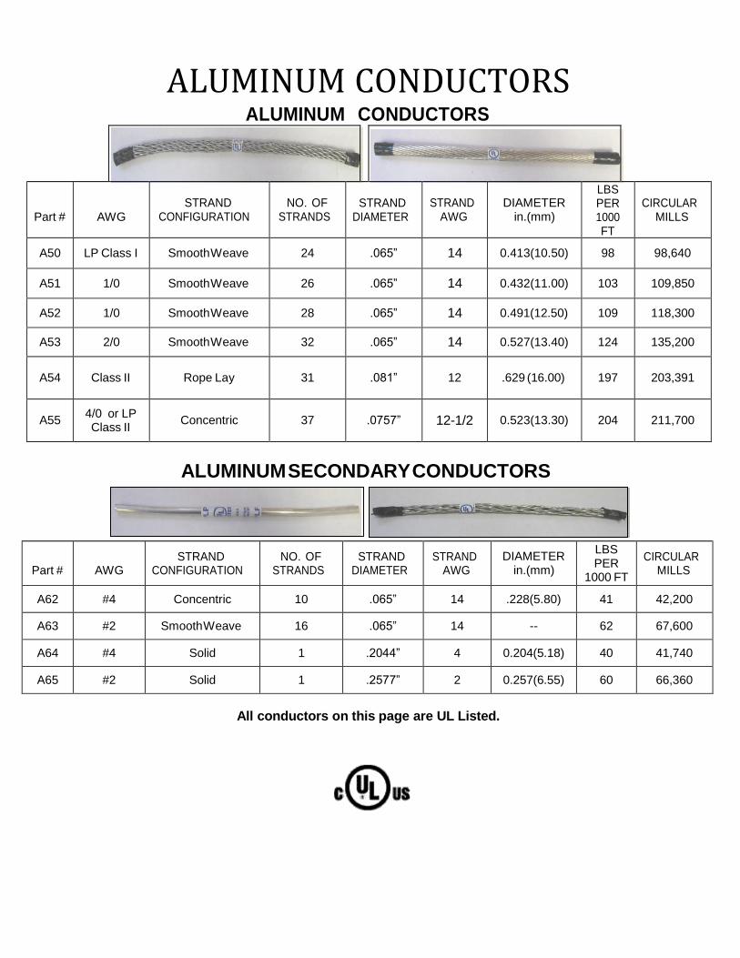
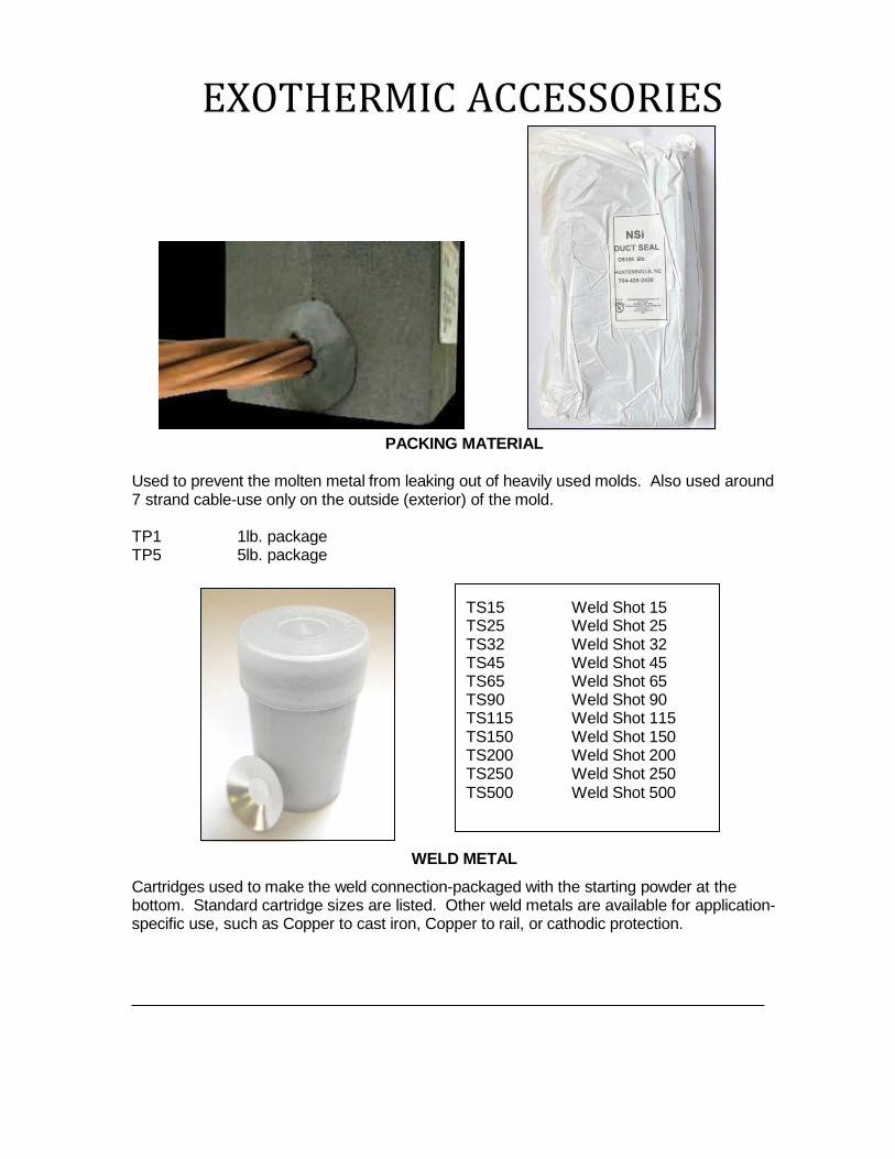
ALUMINUM CONDUCTORS
Part #
AWG
STRAND
CONFIGURATION
NO. OF
STRANDS
STRAND
DIAMETER
STRAND
AWG
DIAMETER
in.(mm)
LBS PER 1000 FT
CIRCULAR
MILLS
A50 LP Class I Smooth Weave 24 .065” 14 0.413(10.50) 98 98,640
P ref e r re d L ig h t n in g P ro t e ct i o n 86 6- 2 9 9- 7 40 6 o r 6 6 0 - 5 6 2- 2 7 7 1 21 0 0 E a s t F i r st St r e e t F a x: 6 6 0 - 5 82 - 2 6 0 3 M ar yv i l l e , M O 6 4 4 6 8 sa l es @ p r ef e r r ed lp . co m
Is s u e Da t e : J u n e 2 0 1 3 P ag e 1 3 w w w .p r ef e r r ed l p . c o m
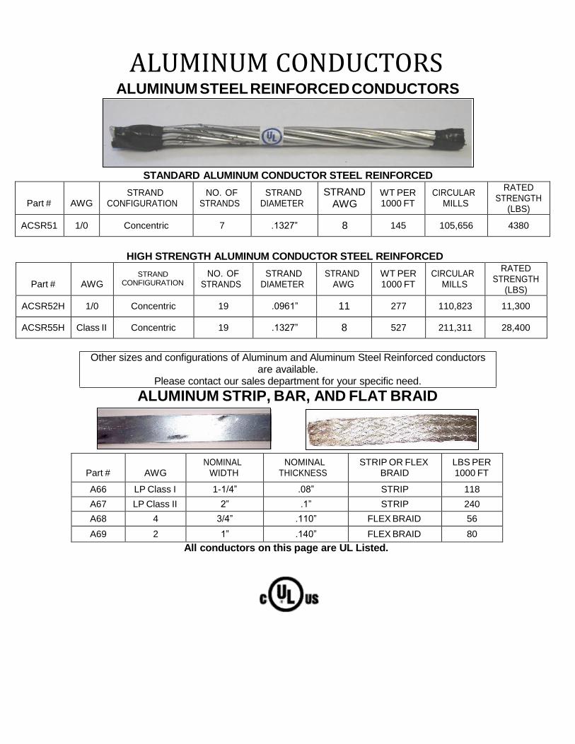
ACSR55H Class II Concentric 19 .1327” 8 527 211,311 28,400
Other sizes and configurations of Aluminum and Aluminum Steel Reinforced conductors are available.
Please contact our sales department for your specific need.
ALUMINUM STRIP, BAR, AND FLAT BRAID
Part #
AWG
NOMINAL WIDTH
NOMINAL THICKNESS
STRIP OR FLEX BRAID
LBS PER 1000 FT
A66 LP Class I 1-1/4” .08” STRIP 118
A67 LP Class II 2” .1” STRIP 240
A68 4 3/4” .110” FLEX BRAID 56
A69 2 1” .140” FLEX BRAID 80
All conductors on this page are UL Listed.
COPPER CONDUCTORS
t io n
P ref e r re d L i g h t n i n g P ro t ec 86 6- 2 9 9- 7 40 6 o r 6 6 0 - 5 6 2- 2 7 7 1 21 0 0 E a s t F i rst St r e e t F a x: 6 6 0 - 5 82 - 2 6 0 3 M ar yv i l l e , M O 6 4 4 6 8 sa l es @ p r ef e r r ed lp . co m
Is s u e Da t e : J u n e 2 0 1 3 P ag e 1 4 w w w .p r ef e r r ed l p . c o m
COPPER CONDUCTORS
Part #
AWG
STRAND
CONFIGURATION
NO. OF
STRANDS
STRAND
DIAMETER
STRAND
AWG
DIAMETER
in.(mm)
TIN
PLATED
LBS PER
1000F T
CIRCULAR
MILLS
C50 LP Class I Smooth Weave 29 .046” 17 0.338(8.60) NO 189 61,350
C50T LP Class I Smooth Weave 29 .046” 17 0.338(8.60) YES 189 61,350
C51 LP Class I Smooth Weave 30 .046” 17 0.360(9.16) NO 191 63,450
Other sizes and configurations of Copper and Copperclad conductors are available. Please contact our sales department for your specific need.
All Conductors on this page are UL Listed.
COPPER CONDUCTORS
COPPER WELD CONDUCTORS
30% CONDUCTIVITY HIGH STRENGH CONCENTRIC CABLE
Part # AWG NO. OF
STRANDS STRAND
DIAMETER STRAND
AWG
WT. PER
1000FT BREAKING
LOAD CIRCULAR
MILLS
CW7X83H 1/0 7 .1285 8 324 11,101 115,586
CW7X53H 4/0 7 .1819 5 649 19,858 231,613
30% CONDUCTIVITY DEAD SOFT ANNEALED CONCENTRIC CABLE
Part # AWG NO. OF
STRANDS STRAND
DIAMETER STRAND
AWG
WT. PER
1000FT BREAKING
LOAD CIRCULAR
MILLS
CW7X3D 4/0 7 .1819 5 649 7148 231,613
Other sizes and configurations of Copperweld Conductors are available. Please contact our sales department for your specific need.
THREADED ROD AND BUS BAR
COPPER STRIP, BAR, AND FLAT BRAID CONDUCTOR
Part # AWG NOMINAL
WIDTH NOMINAL
THICKNESS TIN
PLATED STRIP OR
FLEX BRAID LBS PER 1000 FT
C66 LP Class I 1-1/4” .051” NO STRIP 197
C66T LP Class I 1-1/4” .051” YES STRIP 197
CS.125X1 LP Class I 1” .125” NO STRIP 485
C67 LP Class II 2” .064” NO STRIP 503
C68 #4 3/4" .125” NO FLEX BRAID 128
C68T #4 3/4" .125” YES FLEX BRAID 128
C69 #1 1” .125” NO FLEX BRAID 260
C69T #1 1” .125” YES FLEX BRAID 260
All Conductors listed above are UL Listed
STAINLESS STEEL CONDUCTOR
PART #
AWG NOMINAL
WIDTH NOMINAL
THICKNESS TIN
PLATED STRIP OR
FLEX BRAID LBS PER
1000 FT
S66 LP Class I 1 .06 NO STRIP 210
S69 #1 1 .125 NO FLEX BRAID 240
Other sizes and configurations of Flat Braid conductors are available. Please contact our sales department for your specific need.
THREADED ROD AND BUS BAR
ALL-THREADED ROD
Available in Aluminum, Copper or Stainless Steel. All threaded solid rod. Threads are N.C. Standard and are available in any length up to 12’.
C74 3/8” Copper all threaded rod S75X4 1/2” Stainless Steel 4” long A75 1/2" Aluminum all threaded rod S75X6 1/2” Stainless Steel 6” long C75 1/2” Copper all threaded rod S75X12 1/2” Stainless Steel 12” long S75 1/2” Stainless Steel all threaded rod S75X18 1/2” Stainless Steel 18” long A76 5/8” Aluminum all threaded rod S75X24 1/2” Stainless Steel 24” long C76 5/8” Copper threaded rod
Please indicate length in inches, after the part number, separated by an “x”.
Example: S75X36= 1/2” Stainless Steel-36” long
Threaded rod can be cut to any length up to 12’.
COPPER BUS BAR
Solid Copper or tinned solid Copper bus bar. 100% conductivity. Can be cut to any length up to 12’.
C85X58 1/4” X 5/8” Solid Copper Bar C85 1/4” X 3/4” Solid Copper Bar C86 1/4” X 1” Solid Copper Bar C87 1/4" X 2” Solid Copper Bar C87T 1/4” X 2” Solid Copper Bar Tinned C88 1/4" X 4” Solid Copper Bar C88T 1/4” X 4” Solid Copper Bar Tinned C89 1/4” X 6” Solid Copper Bar C89T 1/4” X 6” Solid Copper Bar Tinned
Please indicate length in inches, after the part number, separated by an “x”. Example: C88X48= 1/4”x4” Copper Bar-48” long
OTHER SOLID BARS A87 1/4” X 2” Solid Aluminum Bar-UL Listed S81 1/8” X 1” Solid Stainless Steel Bar S83 1/8” X 3” Solid Stainless Steel Bar S84 1/8” X 4” Solid Stainless Steel Bar SSFB3/16X2” 3/16” X 2” Solid Stainless Steel Bar-UL Listed
Solid bars can be cut to any length up to 12’.
Please indicate length in inches, after part number, separated by an “X”.
Example: S81X15=1/8” X 1” Stainless Steel bar 15” long.
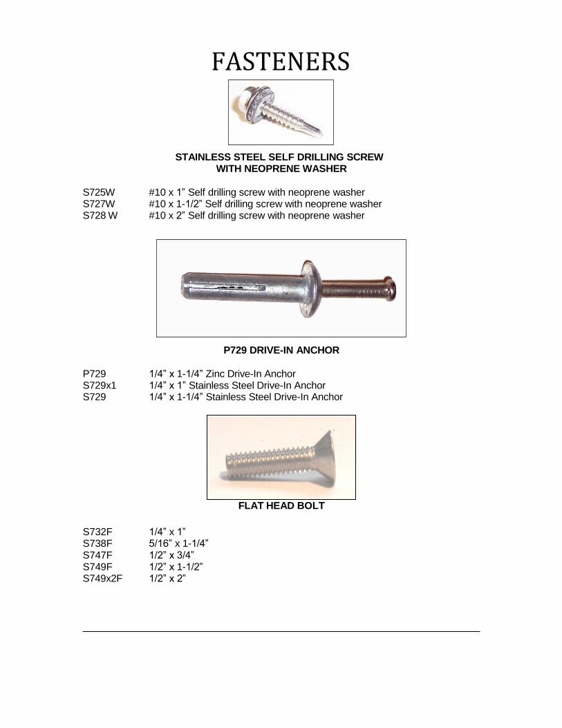
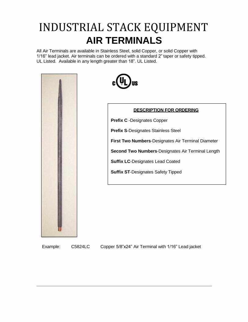
AIR TERMINALS
All air terminals are made of solid Aluminum, Copper or Stainless Steel rod. Air terminals can be ordered with a standard 2” taper or safety tipped. All air terminals are numbered for easy ordering. UL Listed
DESCRIPTION FOR ORDERING
First two numbers–Designates air terminal diameter.
Second two numbers–Designates air terminal length.
Prefix A-Designates Aluminum.
Prefix C– Designates Copper.
Prefix S– Designates Stainless.
Suffix L– Designates Lead Dipped.
Examples:
A1212 Aluminum 1/2" X 12” Air Terminal C3824ST Copper 3/8” X 24” Safety Tipped
Air Terminal C1236LST Copper 1/2" X 36” Leaded Safety
Tipped Air Terminal
Field bends are permissible but must not exceed 90 degrees or have a radius of bend less than 8 inches.
All air terminals over 24” in length – Refer to catalog numbers G150 thru G166 for proper bracing.
AIR TERMINALS
Spring Loaded Air Terminals are available
up to 24” in length.
DESCRIPTION FOR ORDERING
First two numbers–Designates air terminal diameter.
Second two numbers–Designates air
terminal length.
Prefix A– Designates Aluminum.
Prefix C–Designates Copper.
Prefix S– Designates Stainless.
Suffix SPL– Designates Spring Loaded.
Suffix L–Designates Lead Dipped.
Suffix N– Designates Nickel Plated.
Suffix ST–Designates Safety Tipped.
Each Spring Loaded Air Terminal is supplied with
a safety wire.
Examples:
A1212SPL Aluminum 1/2" X 12” Spring Loaded Air Terminal A5824STSPL Aluminum 5/8” X 24” Safety Tipped Spring Loaded Air Terminal C1218NSPL Nickel Plated Copper 1/2” X 18” Spring Loaded Air Terminal
AIR TERMINALS
TUBE AIR TERMINAL
DESCRIPTION FOR ORDERING
First two numbers–Designates air terminal diameter.
Second two numbers –Designates air
terminal length.
Prefix A– Designates Aluminum.
Prefix C– Designates Copper.
Suffix TH – Designates Threaded.
Suffix TF– Designates Tubular Flat.
Examples:
A5812TH Aluminum 5/8” X 12” tube air terminal with threads C5818TF Copper 5/8” X 18” tube air terminal with 3” flat surface
AIR TERMINALS
Concealed Air Terminals DESCRIPTION FOR ORDERING
First Two Numbers-Designates air terminal diameter.
Second Two Numbers-Designates air
terminal length.
Prefix A-Designates Aluminum.
Prefix C-Designates Copper.
Suffix ST-Designates Safety Tipped.
Suffix X_ _TH-Designates Thread
Length.
Example:
Field bends are permissible but must not exceed 90 degrees or have a radius of bend less than 8 inches.
A1224X12TH Aluminum 1/2” X 24 Air Terminal with 12” of thread C1232STX14TH Copper 1/2” X 32 Air Terminal with 14” of thread
Air terminals are made of solid Aluminum or Copper in one length furnished with compatible nuts and washers.
AIR TERMINALS
Off Set Air Terminal DESCRIPTION FOR ORDERING
First Two Numbers-Designates air terminal diameter.
Second Two Numbers-Designates
air terminal length.
Prefix A- Designates Aluminum.
Prefix C- Designates Copper.
Suffix ST- Designates Safety Tipped.
Suffix X_ _OS- Designates offset in
point.
Field bends are permissible but must not exceed 90 degrees or have a radius of bend less than 8 inches.
Example: A1224X4OS Aluminum 1/2” X 24” with 4” offset
Air Terminals are made of solid Aluminum or Copper in one solid length, off set to your specifications. Please provide your exact requirements.
AIR TERMINAL ACCESSORIES
SAFETY BALLS
Safety tipped balls with internal threads for use on extension rods in place of standard air terminals. Available in cast Aluminum or Brass, 1-1/2” diameter. Specify diameter of internal threads: 3/8”, 1/2", or 5/8”. UL Listed.
Machined Aluminum or Brass air terminal cap with internal threads–use where safety to people is desired. Specify diameter of internal threads: 3/8”, 1/2” or 5/8”. UL Listed.
A10112 Aluminum Safety Cap 1/2” threads C10138 Brass Safety Cap 3/8” threads A10158 Aluminum Safety Cap 5/8” threads C10112 Brass Safety Cap 1/2” threads
C10158 Brass Safety Cap 5/8” threads
AIR TERMINAL ACCESSORIES
SPRING ADAPTOR
Stainless Steel Spring Adaptor for use with all sizes of air terminals. For use where fixed air terminals obstruct window washing or moving equipment. Supplied with a safety wire and hardware. UL Listed.
C102 Stainless Steel Spring for 3/8” A.T. with Brass Adapters A103 Stainless Steel Spring for 1/2” A.T. with Aluminum Adapters C103 Stainless Steel Spring for 1/2” A.T. with Brass Adapters A104 Stainless Steel Spring for 5/8” A.T. with Aluminum Adapters C104 Stainless Steel Spring for 5/8” A.T. with Brass Adapters
SAFETY WIRE
Stainless Steel wire attaches around air terminal and to base support to keep air terminal from falling due to breakage. Comes with either A702 or C702 loop and hardware to attach to air terminal.
A105 Stainless Steel Safety Wire with A702 loop and hardware C105 Stainless Steel Safety Wire with C702 loop and hardware
AIR TERMINAL ACCESSORIES
EXTENSION RODS
Solid Aluminum, Copper or Stainless Steel rod threaded at each end for use as a main conductor or air terminal extension. Available in lengths up to 144”. Specify length in inches, after the part number, separated by “x” when ordering. UL Listed
Example: C111X42=1/2” Copper-42” long
A111 A112 A115 A117
1/2” Diameter Aluminum rod 5/8” Diameter Aluminum rod 1” Diameter Aluminum rod 1-1/2” Diameter Aluminum rod
C110 C111 C112 C113
3/8” Diameter Copper rod 1/2” Diameter Copper rod 5/8” Diameter Copper rod 3/4” Diameter Copper rod
S111 S112 S113
1/2” Diameter Stainless Steel rod 5/8” Diameter Stainless Steel rod 3/4” Diameter Stainless Steel rod
STAND-OFF AIR TERIMAL HOLDER
Machined Brass or Aluminum air terminal holder with adjustable threaded rod for irregular surface mounting – 5/16” stainless steel all thread rod for support with two nuts and washers for locking on mounting surface–1/4” set screw on point-standard rod length 6”. Longer or shorter rod available. Fits all air terminals: 3/8”, 1/2” or 5/8”. UL Listed.
A140 Aluminum Air Terminal Holder A141 Aluminum Air Terminal Holder with
2-Bolt Cap-fits 1/2” or 5/8” C140 Brass Air Terminal Holder C141 Brass Air Terminal Holder with
2-Bolt Cap-fits 1/2” or 5/8”
If longer support rod is needed, please add “x” and length.
Example: A140X12 – air terminal holder with 12” extension rod.
AIR TERMINAL ACCESSORIES
143 RIGHT ANGLE AIR TERMINAL EXTENSION
Provides 2” of extension to a vertical mount base.
A14312 1/2” Aluminum Air Terminal Extension C14338 3/8” Brass Air Terminal Extension A14358 5/8” Aluminum Air Terminal Extension C14312 1/2” Brass Air Terminal Extension
C14358 5/8” Brass Air Terminal Extension
147 OFF SET AIR TERMINAL OR CABLE HOLDER
Aluminum or tinned copper strip used to offset air terminal or cable off a curved or flat surface. Offset distance is 1” and ears are 6” long. Uses bolt tension to secure air terminal or cable tightly. Will support solid rods or cable. Other lengths and sizes can be fabricated.
A14712 Aluminum for 1/2" diameter C14738 Tinned copper support for 3/8” A14758 Aluminum for 5/8” diameter C14712 Tinned copper support for 1/2"
C14758 Tinned copper support for 5/8”
AIR TERMINAL ACCESSORIES
A 148 12 4 4
Material Standard Air Terminal Offset O.D. Code Style or (Inches) of
A Constant Cable Size Pipe TC 12=1/2” (Inches)
38=3/8” 58=5/8”
Example: A1481244 Aluminum 1/2” diameter 4” offset 4” O.
148 STRAP TYPE AIR TERMINAL OR CABLE TO PIPE HOLDER
Aluminum or tinned copper strip used to hold an air terminal or cable to a pipe. Use bolt tension to secure air terminal or cable to pipe. Can be fabricated to accommodate any combination with any offset length. Follow the example below to order any size configuration.
Standard sizes are listed below.
D. Pipe
149 OFF SET AIR TERMINAL OR CABLE HOLDER
Aluminum or tinned copper strip used to offset air terminal or cable off a curved or flat surface. Offset distance is 4” and ears are 2” long. Uses bolt tension to secure air terminal or cable tightly. Will support solid rods or cable. Other lengths and sizes can be fabricated.
A14912 Aluminum for 1/2" diameter C14938 Tinned copper support for 3/8” A14958 Aluminum for 5/8” diameter C14912 Tinned copper support for 1/2"
C14958 Tinned copper support for 5/8”
AIR TERMINAL ACCESSORIES
BRACING
Galvanized tripod braces made of mild steel.
Available with two mounting holes or adhesive feet.
For all air terminals over 24” in length. Specify brace size 1/2" or 5/8” when ordering. Use 1/2” brace for 3/8” air terminal.
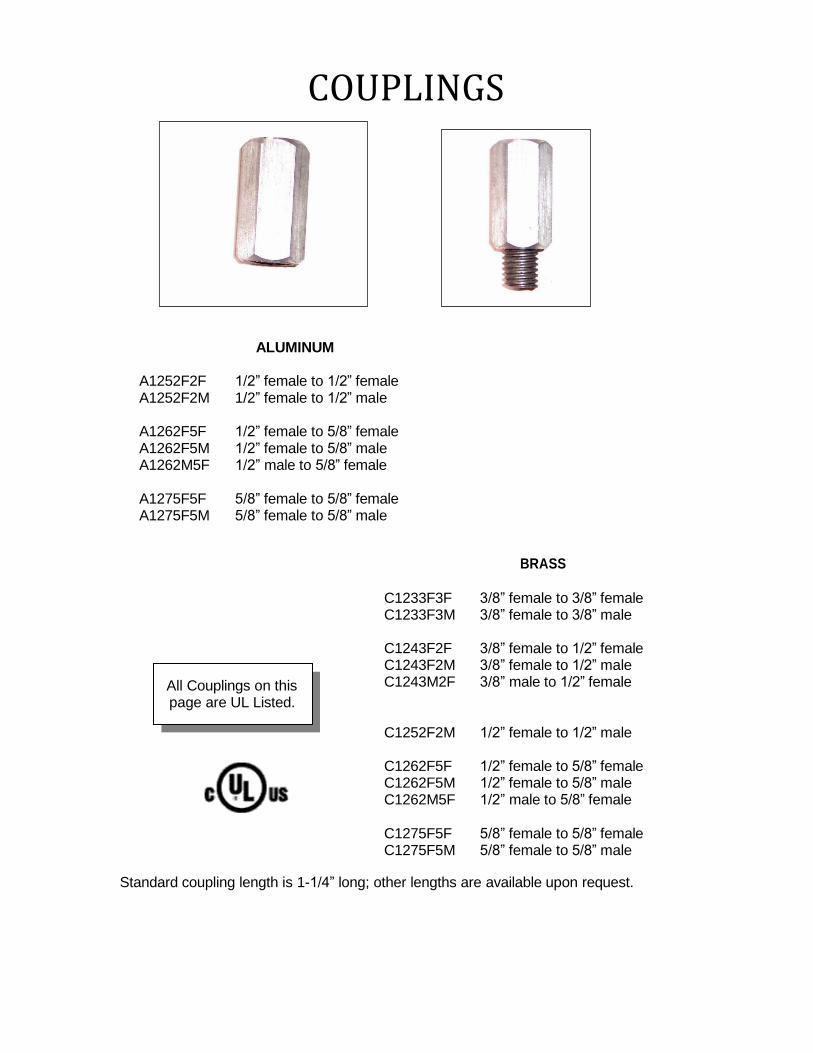
A1252F2F 1/2” female to 1/2” female A1252F2M 1/2” female to 1/2” male
A1262F5F 1/2” female to 5/8” female A1262F5M 1/2” female to 5/8” male A1262M5F 1/2” male to 5/8” female
A1275F5F 5/8” female to 5/8” female A1275F5M 5/8” female to 5/8” male
BRASS
C1233F3F 3/8” female to 3/8” female C1233F3M 3/8” female to 3/8” male
All Couplings on this page are UL Listed.
C1243F2F 3/8” female to 1/2” female C1243F2M 3/8” female to 1/2” male C1243M2F 3/8” male to 1/2” female
C1252F2M 1/2” female to 1/2” male
C1262F5F 1/2” female to 5/8” female C1262F5M 1/2” female to 5/8” male C1262M5F 1/2” male to 5/8” female
C1275F5F 5/8” female to 5/8” female C1275F5M 5/8” female to 5/8” male
Standard coupling length is 1-1/4” long; other lengths are available upon request.
SWIVELS
Swivel action allows air terminal to level on most surfaces.
Several combinations available.
130 SERIES ALUMINUM
A1332F2F 1/2” female to 1/2” female A1332F2M 1/2” female to 1/2” male
A1342F5F 1/2” female to 5/8” female A1342F5M 1/2” female to 5/8” male A1342M5F 1/2” male to 5/8” female
A1355F5F 5/8” female to 5/8” female A1355F5M 5/8” female to 5/8” male
130 SERIES BRASS
All swivels on this
page are UL Listed.
C1313F3F 3/8” female to 3/8” female C1313F3M 3/8” female to 3/8” male
C1323F2F 3/8” female to 1/2” female C1323F2M 3/8” female to 1/2” male C1323M2F 3/8” male to 1/2” female
C1332F2F 1/2” female to 1/2” female C1332F2M 1/2” female to 1/2” male
C1342F5F 1/2” female to 5/8” female C1342F5M 1/2” female to 5/8” male C1342M5F 1/2” male to 5/8” female
C1355F5F 5/8” female to 5/8” female C1355F5M 5/8” female to 5/8” male
SWIVELS/ACCESSORIES
170 Series Swivel
Swivel action allows air terminals to level on most surfaces. Added jam nut allows swivel to be locked in place. UL Listed
A1732F2M
Aluminum
1/2” female to 1/2” male
C1713F3M
Brass
3/8” female to 3/8” male A1742F5M 1/2” female to 5/8” male C1723F2M 3/8” female to 1/2” male A1755F5M 5/8” female to 5/8” male C1732F2M 1/2” female to 1/2” male
C1742F5M 1/2” female to 5/8” male
C1755F5M 5/8” female to 5/8” male
LC 180-1/16” Lead Tube
1/16” thick lead tube to protect air terminals or cable on heavy duty stacks. Also provides a barrier between dissimilar metals. Example: Copper conductor crossing over Aluminum or Steel parapet cap. Specify length in inches, after the part number, separated by an “X” when ordering.
Example: LC180X34X24=3/4” Lead tube-24”long
LC180X916 9/16” I.D. X 1/16” wall lead tube LC180X58 5/8” I.D. X 1/16” wall lead tube LC180X34 3/4” I.D. X 1/16” wall lead tube
ACCESSORIES
S182 MOUNTING BRACKET Stainless Steel mounting bracket used to mount air terminal and base to cooling tower fan stack.
Stainless Steel support bracket used to support air terminal at top of cooling tower fan stack.
S183 1/8”X9” Stainless Steel support bracket
BASES
209 DUAL MOUNT BASE
A cast base threaded for mounting on horizontal or vertical surfaces using screws, 1/4” bolts, 1/4” drive-in anchors, or an adhesive. Bolt tension cap can be turned so cables can run horizontal or vertical. Furnished for air terminal sizes 3/8” and 1/2”. Specify when ordering. UL Listed
A209 Aluminum C209 Bronze C209L Lead Coated Bronze
210 TOP MOUNT BASE A cast base threaded for mounting on horizontal surfaces using screws, 1/4” bolts, 1/4” drive-in anchors, or an adhesive. Bolt tension cap can be turned so cables can run horizontal or vertical. Furnished for all air terminal sizes 3/8”, 1/2”, and 5/8”. Specify when ordering. UL Listed
A210 Aluminum C210 Bronze C210L Lead Coated Bronze
BASES
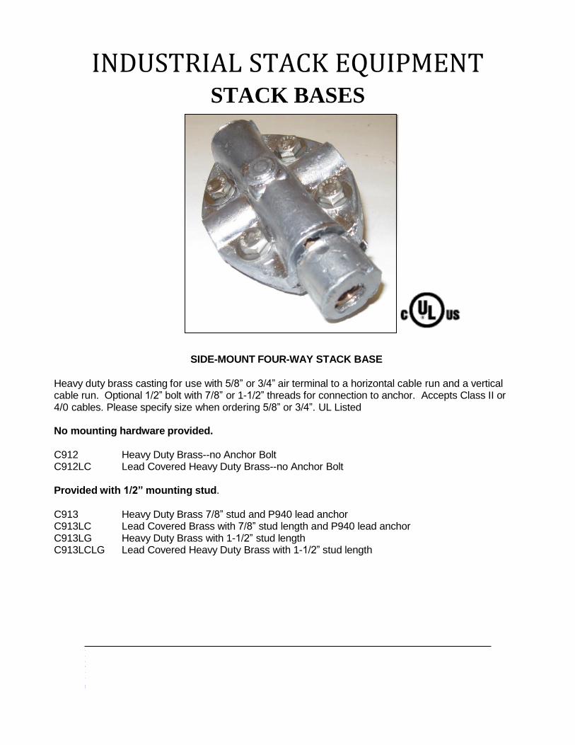
211 SIDE MOUNT BASE
A cast base threaded for mounting on vertical surfaces using screws, 1/4” bolts, or 1/4” drive-in anchors. Bolt tension cap can be turned so cables can run horizontal or vertical. Furnished for all air terminal sizes 3/8”, 1/2”, and 5/8”. Specify when ordering. UL Listed
A211 Aluminum C211 Bronze C211L Lead Coated Bronze
216 UNIVERSAL SWIVEL BASE
This is the most universal base in the industry. The swivel adaptor allows the air terminal to level under most conditions. It can be secured with screws, nails, 1/4” bolts, 1/4” drive-in anchors, or an adhesive. Bolt tension cap can be turned so the cable can run horizontal or vertical. Perfect for skylights, domed or gently sloping roofs, or any uneven surface. Furnished for all air terminal sizes 3/8”, 1/2”, and 5/8”. Specify when ordering. UL Listed
A216 Aluminum C216 Bronze C216L Lead Coated Bronze
BASES
218 OFFSET BASE
A cast base with a 2” offset to clear an overhang when mounted on a vertical surface using screws, 1/4” bolts, or 1/4” drive-in anchors. Bolt tension cap can be turned so cables can run horizontal or vertical. Furnished for all air terminal sizes 3/8”, 1/2”, and 5/8”. Specify when ordering. UL Listed
A218 Aluminum C218 Bronze C218L Lead Coated Bronze
220 ADHESIVE BASE This base has bolt tension cable clamping and can be used on any surface with an adhesive. Furnished for all air terminal sizes 3/8”, 1/2”, and 5/8”. Specify when ordering. UL Listed.
A220 Aluminum C220 Bronze C220L Lead Coated Bronze
BASES
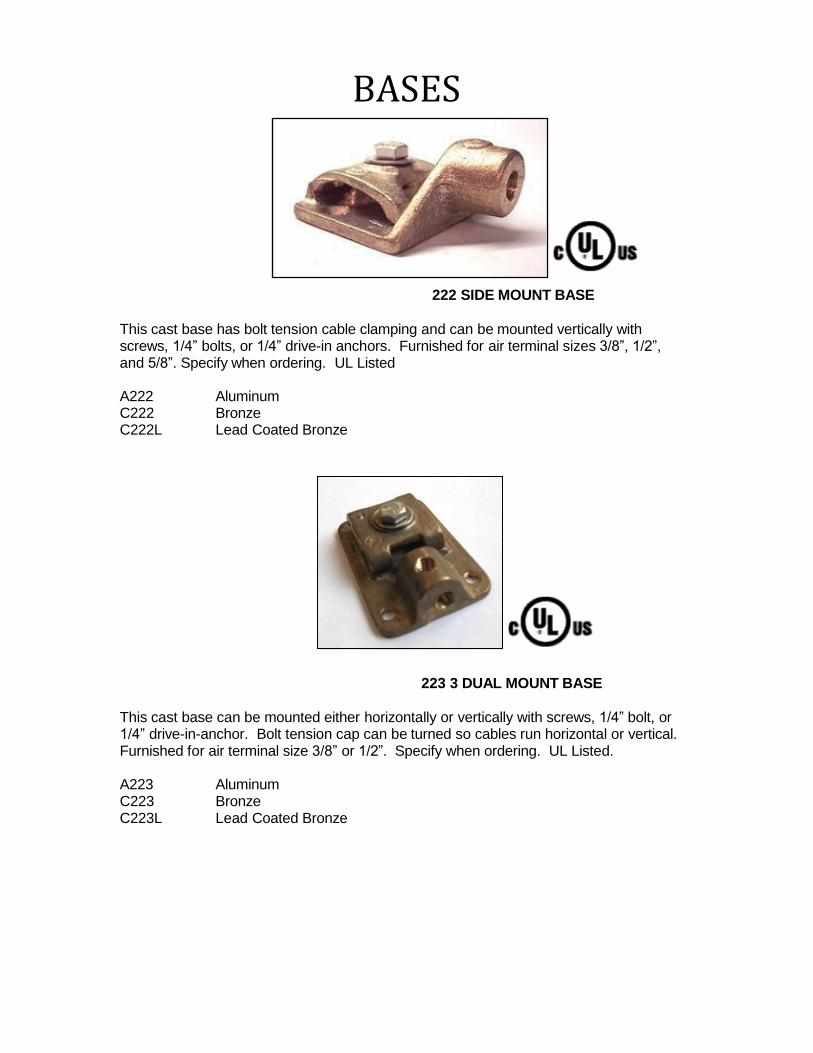
222 SIDE MOUNT BASE
This cast base has bolt tension cable clamping and can be mounted vertically with screws, 1/4” bolts, or 1/4” drive-in anchors. Furnished for air terminal sizes 3/8”, 1/2”, and 5/8”. Specify when ordering. UL Listed
A222 Aluminum C222 Bronze C222L Lead Coated Bronze
223 3 DUAL MOUNT BASE
This cast base can be mounted either horizontally or vertically with screws, 1/4” bolt, or 1/4” drive-in-anchor. Bolt tension cap can be turned so cables run horizontal or vertical. Furnished for air terminal size 3/8” or 1/2”. Specify when ordering. UL Listed.
A223 Aluminum C223 Bronze C223L Lead Coated Bronze
BASES
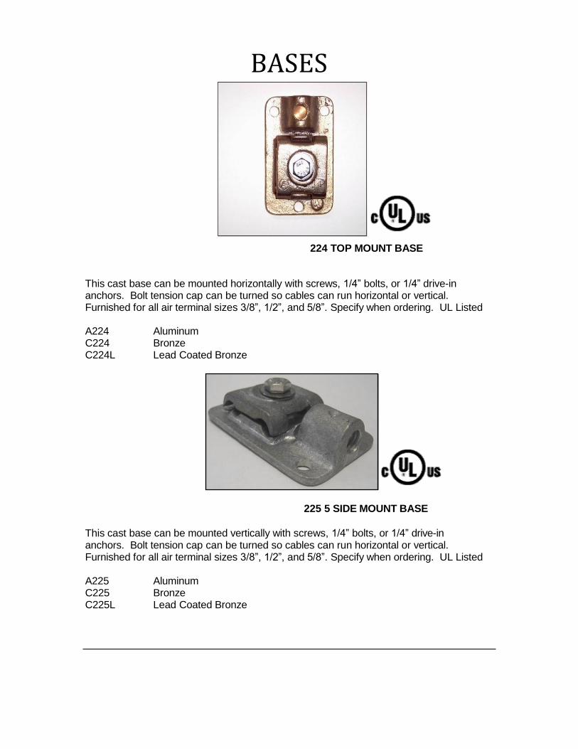
224 TOP MOUNT BASE
This cast base can be mounted horizontally with screws, 1/4” bolts, or 1/4” drive-in anchors. Bolt tension cap can be turned so cables can run horizontal or vertical. Furnished for all air terminal sizes 3/8”, 1/2”, and 5/8”. Specify when ordering. UL Listed
A224 Aluminum C224 Bronze C224L Lead Coated Bronze
225 5 SIDE MOUNT BASE
This cast base can be mounted vertically with screws, 1/4” bolts, or 1/4” drive-in anchors. Bolt tension cap can be turned so cables can run horizontal or vertical. Furnished for all air terminal sizes 3/8”, 1/2”, and 5/8”. Specify when ordering. UL Listed
A225 Aluminum C225 Bronze C225L Lead Coated Bronze
BASES
227 TOP MOUNT BASE
This cast base has bolt tension cable clamping and can be mounted horizontally with screws, 1/4” bolts, or 1/4” drive-in anchors. Furnished for all air terminal sizes 3/8”, 1/2”, and 5/8”. Specify when ordering. UL Listed
A227 Aluminum C227 Bronze C227L Lead Coated Bronze
C228 COPPER NARROW SURFACE BASE
This strap base can be mounted on a narrow surface or ridge roof with screws, nails or adhesive. Base can be modified to accept other anchors. Compression type fingers crimp over cable for easy installation. Available in copper and for Class I structures only. Furnished for air terminal sizes 3/8” and 1/2”. Specify when ordering. UL Listed
C228 Copper C228L Lead Coated Copper
BASES
229 NARROW SURFACE BASE This strap base can be mounted on a narrow surface or ridge roof with screws, nails or adhesive. Base can be modified to accept other anchors. Bolt tension cap provides maximum cable support. Furnished for all air terminal sizes 3/8”, 1/2”, and 5/8”. Specify when ordering. UL Listed
A229 Aluminum C229 Copper C229L Lead Coated Copper
C230 COPPER RIDGE MOUNT BASE
This strap base can be mounted on a ridge roof with screws, nails or adhesive. Base can be modified to accept other anchors. Compression type fingers crimp over cable for easy installation. Available in copper and for Class I structures only. Furnished for air terminal sizes 3/8” and 1/2”. Specify when ordering. UL Listed
C230 Copper C230L Lead Coated Copper
231 RIDGE MOUNT BASE
This strap base can be mounted on ridge roof with screws, nails or adhesive. Base can be modified to accept other anchors. Bolt tension cap provides maximum cable support. Furnished for air terminal sizes 3/8”, 1/2”, and 5/8”. Specify when ordering. UL Listed
A231 Aluminum C231 Copper C231L Lead Coated Copper
BASES
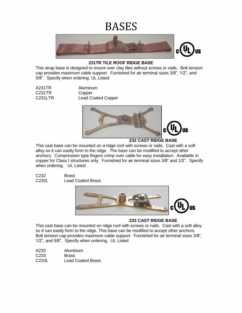
231TR TILE ROOF RIDGE BASE
This strap base is designed to mount over clay tiles without screws or nails. Bolt tension cap provides maximum cable support. Furnished for air terminal sizes 3/8”, 1/2”, and 5/8”. Specify when ordering. UL Listed
A231TR Aluminum C231TR Copper C231LTR Lead Coated Copper
232 CAST RIDGE BASE
This cast base can be mounted on a ridge roof with screws or nails. Cast with a soft alloy so it can easily form to the ridge. The base can be modified to accept other anchors. Compression type fingers crimp over cable for easy installation. Available in copper for Class I structures only. Furnished for air terminal sizes 3/8” and 1/2”. Specify when ordering. UL Listed
C232 Brass C232L Lead Coated Brass
233 CAST RIDGE BASE
This cast base can be mounted on ridge roof with screws or nails. Cast with a soft alloy so it can easily form to the ridge. This base can be modified to accept other anchors. Bolt tension cap provides maximum cable support. Furnished for air terminal sizes 3/8”, 1/2”, and 5/8”. Specify when ordering. UL Listed
A233 Aluminum C233 Brass C233L Lead Coated Brass
BASES
235 CAST STRAIGHT BASE
Cast straight base. Two bolts hold cable firmly and air terminal screws into top to keep cable and air terminal in straight line. Available for air terminal sizes 3/8” and 1/2”. Specify when ordering. Also available in Hex Rod for all air terminal sizes and with set screws in lieu of bolts. UL Listed
CAST HEX ROD A235 C235 C235L
Aluminum Bronze Lead Coated Bronze
A235H C235H C235HL
Aluminum Hex Brass Hex Lead Coated Brass Hex
Note: Please add suffix “SS” to part number for set screw.
236 ROUND ROD BASE
Aluminum or brass machined straight base. Machined from 1” round or 1” Hex rod stock material and available for all air terminal sizes. Specify when ordering. Also available with set screws. UL Listed
A236 Aluminum A236SS Aluminum with set screws C236 Brass C236SS Brass with set screws C236L Lead coated brass C236LSS Lead coated brass with set screws
Note: Add suffix “H” to end of part number to reference Hex rod material.
BASES
P ref e r re d L ig h t n in g P ro t e ct i o n 86 6- 2 9 9- 7 40 6 o r 6 6 0 - 5 6 2- 2 7 7 1 21 0 0 E a s t F i rst St r e e t F a x: 6 6 0 - 5 82 - 2 6 0 3 M ar yv i l l e , M O 6 4 4 6 8 sa l es @ p r ef e r r ed lp . co m Is s
u e Da t e : J u n e 2 0 1 3 P ag e 4 4 w w w .p r ef e r r ed l p . c o m
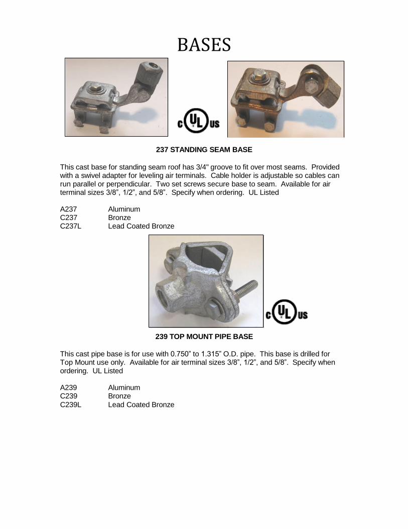
237 STANDING SEAM BASE
This cast base for standing seam roof has 3/4" groove to fit over most seams. Provided with a swivel adapter for leveling air terminals. Cable holder is adjustable so cables can run parallel or perpendicular. Two set screws secure base to seam. Available for air terminal sizes 3/8”, 1/2”, and 5/8”. Specify when ordering. UL Listed
A237 Aluminum C237 Bronze C237L Lead Coated Bronze
239 TOP MOUNT PIPE BASE
This cast pipe base is for use with 0.750” to 1.315” O.D. pipe. This base is drilled for Top Mount use only. Available for air terminal sizes 3/8”, 1/2”, and 5/8”. Specify when ordering. UL Listed
A239 Aluminum C239 Bronze
C239L Lead Coated Bronze
BASES
P ref e r re d L ig h t n in g P ro t e ct i o n 86 6- 2 9 9- 7 40 6 o r 6 6 0 - 5 6 2- 2 7 7 1 21 0 0 E a s t F i rst St r e e t F a x: 6 6 0 - 5 82 - 2 6 0 3 M ar yv i l l e , M O 6 4 4 6 8 sa l es @ p r ef e r r ed lp . co m
Is s u e Da t e : J u n e 2 0 1 3 P ag e 45 w w w .p r ef e r r ed l p . c o m
240 & 242 TOP MOUNT PIPE BASE 241 & 243 SIDE MOUNT PIPE BASE
Cast pipe bases. Base can be drilled for top mounting or side mounting on most pipes. Base sizes range from 1.314” to 1.900” and 1.750” to 2.500”. Each base is numbered for easy ordering. Available for air terminal sizes 3/8”, 1/2”, and 5/8”. Specify when ordering. UL Listed
Top Mount Base with 1.314” to 1.900” Range
A240 Aluminum C240 Bronze C240L Lead Coated Bronze
Side Mount Base with 1.314” to 1.900” Range
A241 Aluminum C241 Bronze
C241L Lead Coated Bronze Top Mount Base with 1.750” to 2.500” Range
A242 Aluminum C242 Bronze C242L Lead Coated Bronze
Side Mount Base with 1.750” to 2.500” Range
A243 Aluminum C243 Bronze C243L Lead Coated Bronze
BASES
P ref e r re d L ig h t n in g P ro t e ct i o n 86 6- 2 9 9- 7 40 6 o r 6 6 0 - 5 6 2- 2 7 7 1 21 0 0 E a s t F i rst St r e e t F a x: 6 6 0 - 5 82 - 2 6 0 3 M ar yv i l l e , M O 6 4 4 6 8 sa l es @ p r ef e r r ed lp . co m Is s
u e Da t e : J u n e 2 0 1 3 P ag e 46 w w w .p r ef e r r ed l p . c o m
STRAP BASES
Formed Aluminum or Copper top mount pipe bases. Any size can be fabricated to order. Please use 247X and O.D. size of pipe. Examples of 11”, 42”, and 48” O.D. pipes are given. Available for all air terminal sizes 3/8”, 1/2”, and 5/8”. Specify when ordering. Also available with bolt tension cap. Add suffix “CH” for cable holder. UL Listed.
Top mount base for pipe size 11”
A247x11 Aluminum top mount base A247x11CH Aluminum base with cable connector C247x11 Copper top mount base C247x11CH Copper base with cable connector
Top mount base for pipe size 42” A247x42 Aluminum top mount base C247x42 Copper top mount base
Top mount base for pipe size 48” A247x48 Aluminum top mount base C247x48 Copper top mount base
BASES
P ref e r re d L ig h t n in g P ro t e ct i o n 86 6- 2 9 9- 7 40 6 o r 6 6 0 - 5 6 2- 2 7 7 1 21 0 0 E a s t F i rst St r e e t F a x: 6 6 0 - 5 82 - 2 6 0 3
M ar yv i l l e , M O 6 4 4 6 8 sa l es @ p r ef e r r ed lp . co m Is s
u e Da t e : J u n e 2 0 1 3 P ag e 47 w w w .p r ef e r r ed l p . c o m
248 & 249 DUAL MOUNT BASE
Cast pipe base is machined for either top mounting or side mounting on pipes. Base sizes range from 1.314” to 1.900” and 1.750” to 2.500”. Available for air terminal sizes 3/8”, 1/2”, and 5/8”. Specify when ordering. UL Listed
Dual Mount Base with 1.314” to 1.900” Range A248 Aluminum C248 Bronze C248L Lead Coated Bronze
Dual Mount Base with 1.750” to 2.500” Range A249 Aluminum C249 Bronze C249L Lead Coated Bronze
250 STAMPED VENT BASE Stamped vent base with no cable holder. Over 8 square inches of contact to direct mount air terminal on continuous metal surface. Furnished for all air terminal sizes 3/8”, 1/2”, and 5/8”. Specify when ordering. UL Listed
A250 Aluminum C250 Copper C250L Tin Plated Copper
BASES
P ref e r re d L ig h t n in g P ro t e ct i o n 86 6- 2 9 9- 7 40 6 o r 6 6 0 - 5 6 2- 2 7 7 1 21 0 0 E a s t F i rst St r e e t F a x: 6 6 0 - 5 82 - 2 6 0 3
M ar yv i l l e , M O 6 4 4 6 8 sa l es @ p r ef e r r ed lp . co m Is s
u e Da t e : J u n e 2 0 1 3 P ag e 48 w w w .p r ef e r r ed l p . c o m
252 CAST VENT BASE Cast vent base with no cable holder. Over 8 square inches of contact to direct mount air terminal on continuous metal surface. Furnished for all air terminal sizes 3/8”, 1/2”, and 5/8”. Specify when ordering. UL Listed
A252 Aluminum C252 Bronze C252L Lead Coated Bronze
262 CONCEALED RIDGE BASE
Stamped Ridge Base with finger cable connector on bottom to conceal cable along ridge. Installed under roofing materials to provide concealment of base and cables. UL Listed.
A262 Aluminum C262 Copper
BASES
P ref e r re d L ig h t n in g P ro t e ct i o n 86 6- 2 9 9- 7 40 6 o r 6 6 0 - 5 6 2- 2 7 7 1 21 0 0 E a s t F i rst St r e e t F a x: 6 6 0 - 5 82 - 2 6 0 3
M ar yv i l l e , M O 6 4 4 6 8 sa l es @ p r ef e r r ed lp . co m Is s
u e Da t e : J u n e 2 0 1 3 P ag e 49 w w w .p r ef e r r ed l p . c o m
290 SERIES U-BOLT SWIVEL BASES WITH 3 SQ IN.
Cast aluminum or brass u-bolt pipe base with swivel point adapter. Available for O.D. pipe ranges from .400” to 8.625” and air terminal sizes 3/8”, 1/2" and 5/8”. Specify when ordering. Provides 3 square inches of contact to pipe. UL Listed.
1” U-Bolt fits .400” to 1.315” O.D. pipes A291 Aluminum C291 Bronze C291L Lead Coated Bronze
2” U-Bolt fits 1.315” to 2.000” O.D. pipes A292 Aluminum C292 Bronze C292L Lead Coated Bronze
C293L Lead Coated Bronze 4” U-Bolt fits 2.750 to 4.500” O.D. pipes A294 Aluminum C294 Bronze C294L Lead Coated Bronze
6” U-Bolt fits 4.500” to 6.750” O.D. pipes A296 Aluminum C296 Bronze C296L Lead Coated Bronze
8” U-Bolt fits 6.000” to 8.625” O.D. pipes A298 Aluminum C298 Copper C298L Lead Coated Bronze
SPLICERS
P ref e r re d L ig h t n in g P ro t e ct i o n 86 6- 2 9 9- 7 40 6 o r 6 6 0 - 5 6 2- 2 7 7 1 21 0 0 E a s t F i rst St r e e t F a x: 6 6 0 - 5 82 - 2 6 0 3 M ar yv i l l e , M O 6 4 4 6 8 sa l es @ p r ef e r r ed lp . co m Is s
u e Da t e : J u n e 2 0 1 3 P ag e 50 w w w .p r ef e r r ed l p . c o m
301 TEE SPLICER
Stamped tee splicer with compression type fingers to crimp around cable. Made from 14 gauge Copper or 10 gauge Aluminum stock. For use with all main size conductors on Class I structures only. UL Listed
A301 Aluminum C301 Copper C301L Lead Coated Copper
303 STRAIGHT SPLICER Stamped straight splicer with compression type fingers to crimp around ends of cable for a straight connection. Made from 14 gauge Copper or 10 gauge Aluminum stock. For use with all main size conductors on Class I structures only. UL Listed
A303 Aluminum C303 Copper C303L Lead Coated Copper
SPLICERS
P ref e r re d L ig h t n in g P ro t e ct i o n 86 6- 2 9 9- 7 40 6 o r 6 6 0 - 5 6 2- 2 7 7 1 21 0 0 E a s t F i rst St r e e t F a x: 6 6 0 - 5 82 - 2 6 0 3 M ar yv i l l e , M O 6 4 4 6 8 sa l es @ p r ef e r r ed lp . co m Is s
u e Da t e : J u n e 2 0 1 3 P ag e 51 w w w .p r ef e r r ed l p . c o m
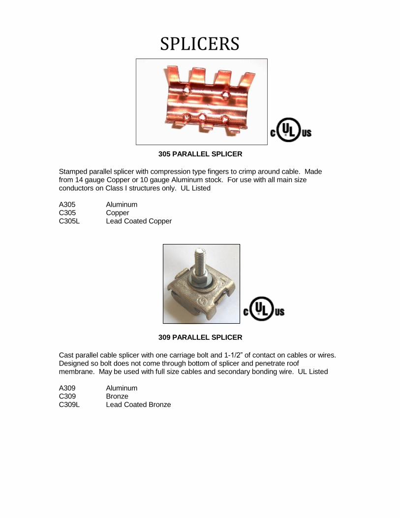
305 PARALLEL SPLICER
Stamped parallel splicer with compression type fingers to crimp around cable. Made from 14 gauge Copper or 10 gauge Aluminum stock. For use with all main size conductors on Class I structures only. UL Listed
A305 Aluminum C305 Copper C305L Lead Coated Copper
309 PARALLEL SPLICER
Cast parallel cable splicer with one carriage bolt and 1-1/2” of contact on cables or wires. Designed so bolt does not come through bottom of splicer and penetrate roof membrane. May be used with full size cables and secondary bonding wire. UL Listed
A309 Aluminum C309 Bronze C309L Lead Coated Bronze
SPLICERS
P ref e r re d L ig h t n in g P ro t e ct i o n 86 6- 2 9 9- 7 40 6 o r 6 6 0 - 5 6 2- 2 7 7 1 21 0 0 E a s t F i rst St r e e t F a x: 6 6 0 - 5 82 - 2 6 0 3 M ar yv i l l e , M O 6 4 4 6 8 sa l es @ p r ef e r r ed lp . co m Is s
u e Da t e : J u n e 2 0 1 3 P ag e 52 w w w .p r ef e r r ed l p . c o m
310 CAST PARALLEL SPLICER
Cast parallel cable splicer with single bolt tension and 1-1/2” of contact on cables and wires. Splicer may be used with full size cables or secondary bonding wire. UL Listed
A310 Aluminum C310 Bronze C310L Lead Coated Bronze
C311 PARALLEL SPLICER
Cast parallel cable splicer with double carriage bolt tension and 2” of contact on cable and wires. Splicer may be used with full size cables or secondary bonding wires. UL Listed
A311 Aluminum C311 Bronze C311L Lead Coated Bronze
SPLICERS
P ref e r re d L ig h t n in g P ro t e ct i o n 86 6- 2 9 9- 7 40 6 o r 6 6 0 - 5 6 2- 2 7 7 1 21 0 0 E a s t F i rst St r e e t F a x: 6 6 0 - 5 82 - 2 6 0 3 M ar yv i l l e , M O 6 4 4 6 8 sa l es @ p r ef e r r ed lp . co m
Is s u e Da t e : J u n e 2 0 1 3 P ag e 53 w w w .p r ef e r r ed l p . c o m
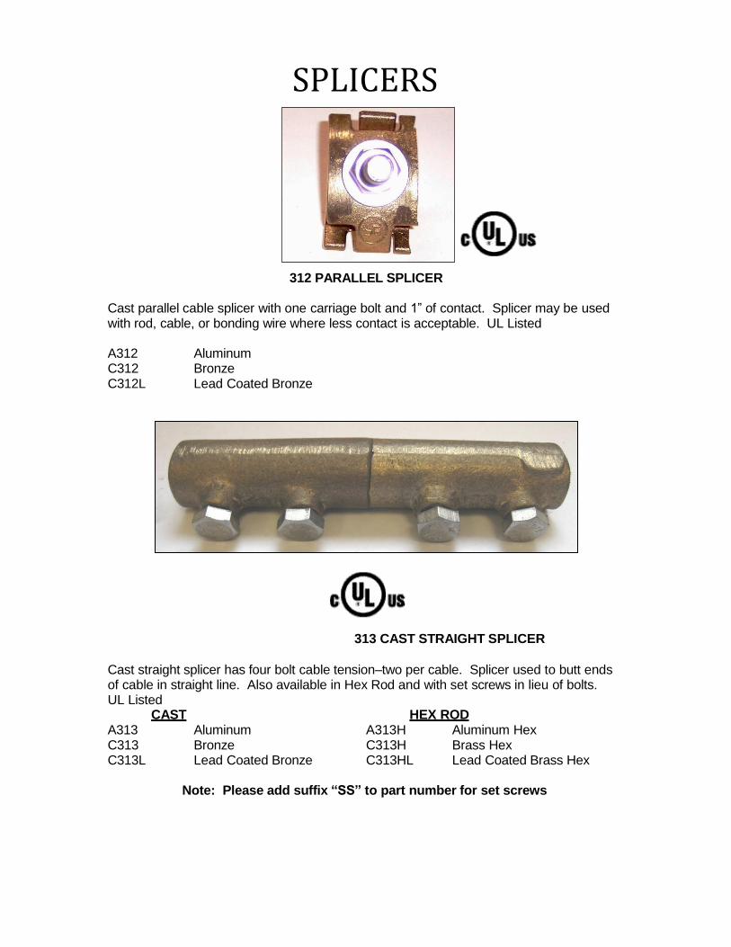
312 PARALLEL SPLICER Cast parallel cable splicer with one carriage bolt and 1” of contact. Splicer may be used with rod, cable, or bonding wire where less contact is acceptable. UL Listed
A312 Aluminum C312 Bronze C312L Lead Coated Bronze
313 CAST STRAIGHT SPLICER
Cast straight splicer has four bolt cable tension–two per cable. Splicer used to butt ends of cable in straight line. Also available in Hex Rod and with set screws in lieu of bolts. UL Listed
CAST HEX ROD A313 Aluminum A313H Aluminum Hex C313 Bronze C313H Brass Hex C313L Lead Coated Bronze C313HL Lead Coated Brass Hex
Note: Please add suffix “SS” to part number for set screws
SPLICERS
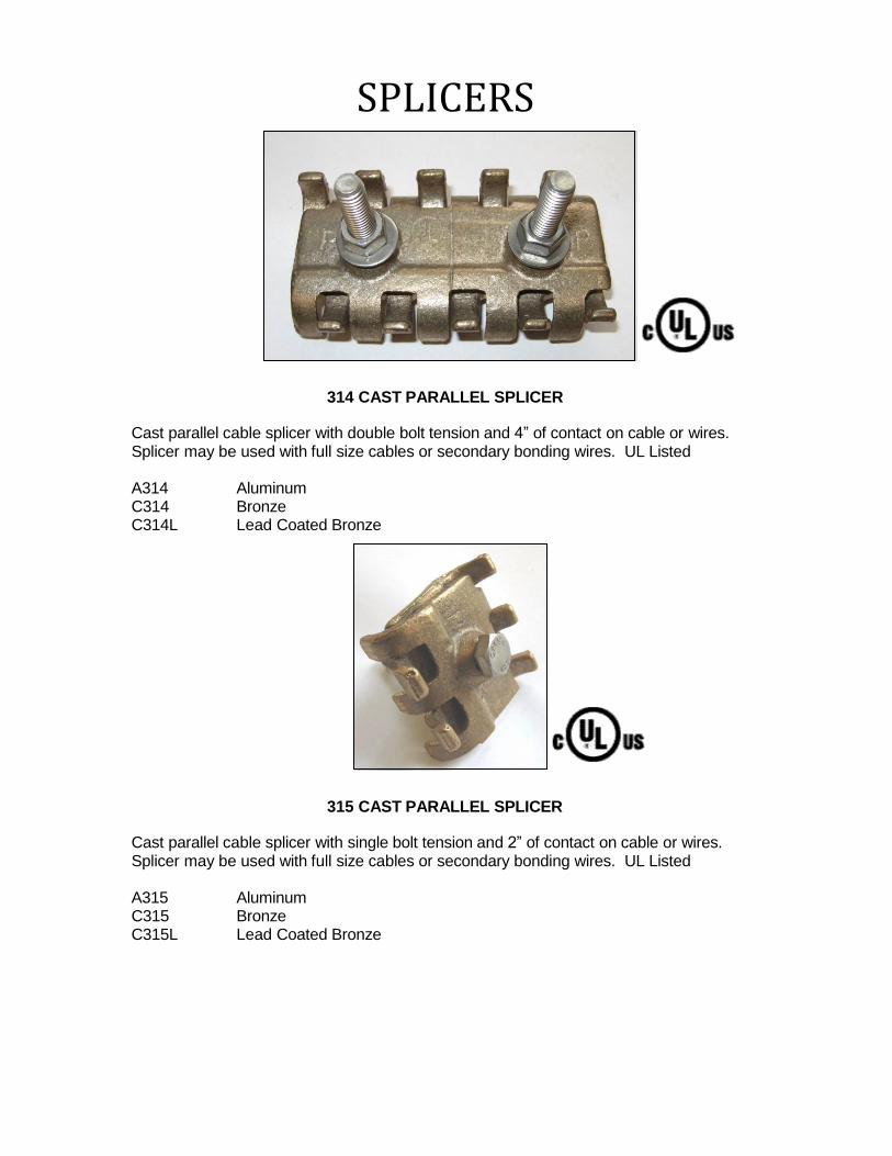
314 CAST PARALLEL SPLICER Cast parallel cable splicer with double bolt tension and 4” of contact on cable or wires. Splicer may be used with full size cables or secondary bonding wires. UL Listed
A314 Aluminum C314 Bronze C314L Lead Coated Bronze
315 CAST PARALLEL SPLICER
Cast parallel cable splicer with single bolt tension and 2” of contact on cable or wires. Splicer may be used with full size cables or secondary bonding wires. UL Listed
A315 Aluminum C315 Bronze C315L Lead Coated Bronze
SPLICERS
P ref e r re d L ig h t n in g P ro t e ct i o n 86 6- 2 9 9- 7 40 6 o r 6 6 0 - 5 6 2- 2 7 7 1 21 0 0 E a s t F i rst St r e e t F a x: 6 6 0 - 5 82 - 2 6 0 3 M ar yv i l l e , M O 6 4 4 6 8 sa l es @ p r ef e r r ed lp . co m
Is s u e Da t e : J u n e 2 0 1 3 P ag e 55 w w w .p r ef e r r ed l p . c o m
A320 BIMETALLIC SPLICER
Cast bimetallic cable splicer for making connections between aluminum and copper cables in a straight line. Two-bolt tension on each cable for making a strong connection. Use with all main size conductors. UL Listed
A320 Aluminum to Copper Bimetallic
A3 20 H SS BI M E T AL LI C SPLI CER
Machined bimetallic straight splicer for making connections between aluminum and copper cables. Used to make connection inside 1” PVC Conduit. Use with all main size conductors. UL Listed.
A320HSS Aluminum to Copper Bimetallic
SPLICERS
P ref e r re d L ig h t n in g P ro t e ct i o n 86 6- 2 9 9- 7 40 6 o r 6 6 0 - 5 6 2- 2 7 7 1 21 0 0 E a s t F i rst St r e e t F a x: 6 6 0 - 5 82 - 2 6 0 3
M ar yv i l l e , M O 6 4 4 6 8 sa l es @ p r ef e r r ed lp . co m Is s
u e Da t e : J u n e 2 0 1 3 P ag e 56 w w w .p r ef e r r ed l p . c o m
A322 BIMETALLIC SPLICER 323 DISCONNECTS
Cast bimetallic cable splicer for making connections between Aluminum and Copper cables. Single bolt tension caps allow the cables to come from a variety of directions. Use with all main size conductors. Eliminates the use of an additional splicer. UL Listed
A322 Aluminum to Copper Bimetallic
Cast cable disconnects used for testing system continuity or ground resistance. Single bolt tension caps allow for easy disconnection. UL Listed
A323 Aluminum to Aluminum Disconnect C323 Copper to Copper Disconnect
325 CAST TEE SPLICER
Cast tee cable splicer has bolt tension for connections with all main size conductors. UL Listed
A325 Aluminum C325 Bronze C325L Lead Coated Bronze
SPLICERS
P ref e r re d L ig h t n in g P ro t e ct i o n 86 6- 2 9 9- 7 40 6 o r 6 6 0 - 5 6 2- 2 7 7 1 21 0 0 E a s t F i rst St r e e t F a x: 6 6 0 - 5 82 - 2 6 0 3
M ar yv i l l e , M O 6 4 4 6 8 sa l es @ p r ef e r r ed lp . co m Is s
u e Da t e : J u n e 2 0 1 3 P ag e 57 w w w .p r ef e r r ed l p . c o m
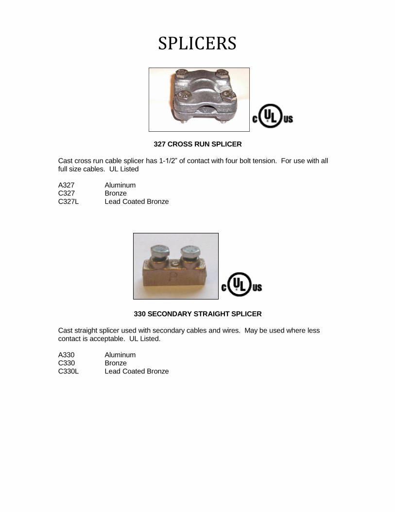
327 CROSS RUN SPLICER
Cast cross run cable splicer has 1-1/2” of contact with four bolt tension. For use with all full size cables. UL Listed
A327 Aluminum C327 Bronze C327L Lead Coated Bronze
330 SECONDARY STRAIGHT SPLICER
Cast straight splicer used with secondary cables and wires. May be used where less contact is acceptable. UL Listed.
A330 Aluminum C330 Bronze C330L Lead Coated Bronze
BONDING CLAMPS, PLATES AND LUGS
P ref e r re d L ig h t n in g P ro t e ct i o n 86 6- 2 9 9- 7 40 6 o r 6 6 0 - 5 6 2- 2 7 7 1 21 0 0 E a s t F i rst St r e e t F a x: 6 6 0 - 5 82 - 2 6 0 3
M ar yv i l l e , M O 6 4 4 6 8 sa l es @ p r ef e r r ed lp . co m Is s
u e Da t e : J u n e 2 0 1 3 P ag e 5 8 w w w .p r ef e r r ed l p . c o m
404 CAST BONDING PLATE
Cast bonding plate with 3 square inches of contact. Bolt tension cap can be turned so cables can run horizontal or vertical. For use with all full size cables. UL Listed
A404 Aluminum C404 Bronze C404L Lead Coated Bronze
406 STAMPED BONDING PLATE
Stamped bonding plate with 8 square inches of contact. Bolt tension cap provides maximum cable support. For use with all full size cables. UL Listed
A406 Aluminum C406 Copper C406L Lead Coated Copper
BONDING CLAMPS, PLATES AND LUGS
P ref e r re d L ig h t n in g P ro t e ct i o n 86 6- 2 9 9- 7 40 6 o r 6 6 0 - 5 6 2- 2 7 7 1 21 0 0 E a s t F i rst St r e e t F a x: 6 6 0 - 5 82 - 2 6 0 3
M ar yv i l l e , M O 6 4 4 6 8 sa l es @ p r ef e r r ed lp . co m Is s
u e Da t e : J u n e 2 0 1 3 P ag e 5 9 w w w .p r ef e r r ed l p . c o m
C407 COPPER STAMPED FINGER BONDING PLATE
Stamped bonding plate with 8 square inches of contact. Compression type fingers crimp over cable for easy installation. Available in copper and for Class I structures only. For use with all full size cables. UL Listed
C407 Copper C407L Lead Coated Copper
410 CAST BONDING PLATE
Cast bonding plate with 8 square inches of contact surface. Holes provided for 1/4” bolts or smaller screws. Bolt tension cap can be turned so cables can run any direction. For use with all full size cables. UL Listed
A410 Aluminum C410 Bronze C410L Lead Coated Bronze
BONDING CLAMPS, PLATES AND LUGS
P ref e r re d L ig h t n in g P ro t e ct i o n 86 6- 2 9 9- 7 40 6 o r 6 6 0 - 5 6 2- 2 7 7 1 21 0 0 E a s t F i rst St r e e t F a x: 6 6 0 - 5 82 - 2 6 0 3 M ar yv i l l e , M O 6 4 4 6 8 sa l es @ p r ef e r r ed lp . co m Is s u e Da t e : J u n e 2 0 1 3 P ag e 6 9 w w w .p r ef e r r ed l p . c o m
411 CAST BONDING PLATE
Cast bonding plate with 8 square inches of contact. Bolt tension cap has 1-1/2” of contact. For use with all full size cables. UL Listed
A411 Aluminum C411 Bronze C411L Lead Coated Bronze
412 BONDING LUG
Cast bonding lug with 3 square inches of contact surface. Available for bolt sizes 1/4”, 3/8”, 1/2”, and 5/8” diameter. Anchor holed drilled in center. Bolt tension cap can turn so cable can be connected from any direction. For use with all full size cables. Specify bolt size when ordering. UL Listed
A412 Aluminum C412 Bronze C412L Lead Coated Bronze
Example of bolt size: A41212-Aluminum Bonding lug with 1/2” bolt hole
BONDING CLAMPS, PLATES AND LUGS
P ref e r re d L ig h t n in g P ro t e ct i o n 86 6- 2 9 9- 7 40 6 o r 6 6 0 - 5 6 2- 2 7 7 1 21 0 0 E a s t F i rst St r e e t F a x: 6 6 0 - 5 82 - 2 6 0 3
M ar yv i l l e , M O 6 4 4 6 8 sa l es @ p r ef e r r ed lp . co m Is s
u e Da t e : J u n e 2 0 1 3 P ag e 6 1 w w w .p r ef e r r ed l p . c o m
413 BONDING LUG
Cast bonding lug with 3 square inches of contact surface. Available for bolt sizes 1/4”, 3/8” and 1/2”diameter. Anchor holed drilled at top. Bolt tension cap can turn so cable can be connected from any direction. For use with all full size cables. Specify bolt size when ordering. UL Listed
A413 Aluminum C413 Bronze C413L Lead Coated Bronze
414 C-CLAMP BONDING CLAMP Cast bonding clamp has 8 square inches of surface contact. C-type clamp allows easy installation on I-beams or other flat areas up to 1” thickness. Bolt tension cap has 1-1/2” of cable contact. For use with all full size cables. UL Listed
A414 Aluminum C414 Bronze C414L Lead Coated Bronze
BONDING CLAMPS, PLATES AND LUGS
P ref e r re d L ig h t n in g P ro t e ct i o n 86 6- 2 9 9- 7 40 6 o r 6 6 0 - 5 6 2- 2 7 7 1 21 0 0 E a s t F i rst St r e e t F a x: 6 6 0 - 5 82 - 2 6 0 3
M ar yv i l l e , M O 6 4 4 6 8 sa l es @ p r ef e r r ed lp . co m Is s
u e Da t e : J u n e 2 0 1 3 P ag e 6 2 w w w .p r ef e r r ed l p . c o m
415 C-CLAMP BONDING CLAMP
Cast bonding clamp has 8 square inches of surface contact. C-type clamp allows easy installation on I-beams or other flat areas up to 3” thickness. Bolt tension cap has 1-1/2” of cable contact. For use with all full size cables. UL Listed A415 Aluminum C415 Bronze C415L Lead Coated Bronze
416-418 PIPE CLAMP
Cast pipe grounding clamp with 1-1/2” of contact. Available in three pipe sizes. For use with full size cables. UL Listed Pipe Range .750” to 1.315” O.D. Pipe Range 1.750” to 2.500” O.D. A416 Aluminum A418 Aluminum C416 Bronze C418 Bronze C416L Lead Coated Bronze C418L Lead Coated Bronze Pipe Range 1.315” to 1.900” O.D. A417 Aluminum C417 Bronze C417L Lead Coated Bronze
420 GUTTER CLAMP
Stamped gutter clamp with compression fingers to crimp over gutter edge and cable. Use with all full size cables. Available for Class I structures only. UL Listed
A420 Aluminum C420 Copper C420L Lead Coated Copper
BONDING CLAMPS, PLATES AND LUGS
P ref e r re d L ig h t n in g P ro t e ct i o n 86 6- 2 9 9- 7 40 6 o r 6 6 0 - 5 6 2- 2 7 7 1 21 0 0 E a s t F i rst St r e e t F a x: 6 6 0 - 5 82 - 2 6 0 3 M ar yv i l l e , M O 6 4 4 6 8 sa l es @ p r ef e r r ed lp . co m Is s
u e Da t e : J u n e 2 0 1 3 P ag e 6 3 w w w .p r ef e r r ed l p . c o m
A422 Aluminum A423 Aluminum C422 Bronze C423 Bronze C422L Lead Coated Bronze C423L Lead Coated Bronze
A424 Aluminum A426 Aluminum C424 Bronze C426 Bronze C424L Lead Coated Bronze C426L Lead Coated Bronze
1” U-BOLT BONDING CLAMP
Cast U-Bolt bonding clamp for use with pipe or round bar from .400” to 1.315” Can be used with cable and wire sizes from #6 to 250 MCM. UL Listed
1” U-Bolt fits .400” to 1.315” O.D. pipes A421 Aluminum C421 Bronze C421L Lead Coated Bronze
2” – 8” U-BOLT BONDING CLAMPS
Cast U-Bolt pipe clamps. Provides 1-1/2” of contact on pipe and cable. Use with all full size conductors. Fits pipe sizes 1.315” to 8.625”. UL Listed
2” U-Bolt fits 1.315” to 2.000” O.D. pipes 3” U-Bolt fits 1.900” to 3.000” O.D. pipes
4” U-Bolt fits 2.75” to 4.50” O.D. pipes 6” U-Bolt fits 4.50” to 6.75” O.D. pipes
P ref e r re d L ig h t n in g P ro t e ct i o n 86 6- 2 9 9- 7 40 6 o r 6 6 0 - 5 6 2- 2 7 7 1 21 0 0 E a s t F i rst St r e e t F a x: 6 6 0 - 5 82 - 2 6 0 3 M ar yv i l l e , M O 6 4 4 6 8 sa l es @ p r ef e r r ed lp . co m
Is s u e Da t e : J u n e 2 0 1 3 P ag e 64 w w w .p r ef e r r ed l p . c o m
430 SECONDARY BONDING CLAMP
Cast bolt tension secondary bonding lug for connections to VTR’s, roof drains, flashings, etc. For use with secondary wire. UL Listed
A430 Aluminum C430 Bronze C430L Lead Coated Bronze
432 SECONDARY BONDING LUG
Cast terminal bonding lug with 2 bolt tension on secondary wires. Lug can be secured with a screw, 1/4” drive-in anchor, or 1/4” bolt. For use with all secondary wires. UL Listed
P ref e r re d L ig h t n in g P ro t e ct i o n 86 6- 2 9 9- 7 40 6 o r 6 6 0 - 5 6 2- 2 7 7 1 21 0 0 E a s t F i rst St r e e t F a x: 6 6 0 - 5 82 - 2 6 0 3 M ar yv i l l e , M O 6 4 4 6 8 sa l es @ p r ef e r r ed lp . co m Is s
u e Da t e : J u n e 2 0 1 3 P ag e 65 w w w .p r ef e r r ed l p . c o m
433 BONDING CLAMP
Cast bolt tension bonding clamp with 3 square inches of contact secures to I-beams, purlin flange, etc. For use with all full size cables and secondary wires. UL Listed
A433 Aluminum C433 Bronze C433L Lead Coated Bronze
434 SECONDARY BONDING CLAMP
Cast bolt tension bonding clamp secures to I-beams, purlin flange, etc. For use with all full size cables and secondary wires. For secondary bond only. UL Listed
A434 Aluminum C434 Bronze C434L Lead Coated Bronze
BONDING CLAMPS, PLATES AND LUGS
P ref e r re d L ig h t n in g P ro t e ct i o n 86 6- 2 9 9- 7 40 6 o r 6 6 0 - 5 6 2- 2 7 7 1 21 0 0 E a s t F i rst St r e e t F a x: 6 6 0 - 5 82 - 2 6 0 3 M ar yv i l l e , M O 6 4 4 6 8 sa l es @ p r ef e r r ed lp . co m
Is s u e Da t e : J u n e 2 0 1 3 P ag e 66 w w w .p r ef e r r ed l p . c o m
FLEXIBLE BONDING STRAP
Extra flexible bonding strap for use in moving or vibrating metal objects. Two sizes standard 10” and 12”. Any size can be fabricated. Other materials available.
1-1/4” wide strap with a secondary terminal lug (catalog number 432) attached. Fits all secondary wires. Any size strap can be fabricated. UL Listed
A438 Aluminum strap for 2” pipe C438 Tinned copper strap for 2” pipe
A439 Aluminum strap for 4” pipe C439 Tinned copper strap for 4” pipe
A440 Aluminum strap for 6” pipe C440 Tinned copper strap for 6” pipe
BONDING CLAMPS, PLATES AND LUGS
P ref e r re d L ig h t n in g P ro t e ct i o n 86 6- 2 9 9- 7 40 6 o r 6 6 0 - 5 6 2- 2 7 7 1 21 0 0 E a s t F i rst St r e e t F a x: 6 6 0 - 5 82 - 2 6 0 3 M ar yv i l l e , M O 6 4 4 6 8 sa l es @ p r ef e r r ed lp . co m Is s
u e Da t e : J u n e 2 0 1 3 P ag e 67 w w w .p r ef e r r ed l p . c o m
PRIMARY BONDING STRAP 1-1/4” wide strap with a parallel cable connector (catalog number 310) attached. Fits all main size cables and secondary wires. Any size strap can be fabricated. UL Listed
A442 Aluminum strap for 2” pipe C442 Tinned copper strap for 2” pipe
A444 Aluminum strap for 4” pipe C444 Tinned copper strap for 4” pipe
A446 Aluminum strap for 6” pipe C446 Tinned copper strap for 6” pipe
A448 Aluminum strap for 8” pipe C448 Tinned copper strap for 8” pipe
A450 Aluminum strap for 10” pipe C450 Tinned copper strap for 10” pipe
A450X12 Aluminum strap for 12” pipe C450X12 Tinned copper strap for 12” pipe
Note: For longer straps, please use Part # C450X_ _ with the “--” designating the diameter of the pipe. For Example: A tinned Copper strap for a 36” diameter pipe would be part number C450X36.
THRU WALL, THRU ROOF & ACCESSORIES
P ref e r re d L ig h t n in g P ro t e ct i o n 86 6- 2 9 9- 7 40 6 o r 6 6 0 - 5 6 2- 2 7 7 1 21 0 0 E a s t F i rst St r e e t F a x: 6 6 0 - 5 82 - 2 6 0 3 M ar yv i l l e , M O 6 4 4 6 8 sa l es @ p r ef e r r ed lp . co m
Is s u e Da t e : J u n e 2 0 1 3 P ag e 68 w w w .p r ef e r r ed l p . c o m
PRIMARY WATER PIPE BONDING STRAP 2” wide strap with a parallel cable connector (catalog number 310) attached. Fits all main size cables. Any size strap can be fabricated. UL Listed
A452 Aluminum strap for 2” pipe C452 Tinned copper strap for 2” pipe
A454 Aluminum strap for 4” pipe C454 Tinned copper strap for 4” pipe
A456 Aluminum strap for 6” pipe C456 Tinned copper strap for 6” pipe
A458 Aluminum strap for 8” pipe C458 Tinned copper strap for 8” pipe
A460 Aluminum strap for 10” pipe C460 Tinned copper strap for 10” pipe
A460X12 Aluminum strap for 12” pipe C460X12 Tinned copper strap for 12” pipe
Note: For longer straps, please use Part # C460X_ _with the “--” designating the diameter of the pipe. For Example: A tinned Copper strap for a 36” diameter pipe
would be part number C460X36.
THRU WALL, THRU ROOF & ACCESSORIES
P ref e r re d L ig h t n in g P ro t e ct i o n 86 6- 2 9 9- 7 40 6 o r 6 6 0 - 5 6 2- 2 7 7 1 21 0 0 E a s t F i rst St r e e t F a x: 6 6 0 - 5 82 - 2 6 0 3 M ar yv i l l e , M O 6 4 4 6 8 sa l es @ p r ef e r r ed lp . co m Is s u e Da t e : J u n e 2 0 1 3 P ag e 6 9 w w w .p r ef e r r ed l p . c o m
481-483 ROD CLAMP
Cast rod clamp has 1-1/2” on contact and two bolt tension. Used to bond all full size cable to open end rod. UL Listed
A481 Aluminum 1/2” rod clamp A482 Aluminum 5/8” rod clamp A483 Aluminum 3/4" rod clamp
C481 Bronze 1/2” rod clamp C481L Lead Coated Bronze 1/2” rod clamp C482 Bronze 5/8” rod clamp C482L Lead Coated Bronze 5/8” rod clamp C483 Bronze 3/4” rod clamp C483L Lead Coated Bronze 3/4” rod clamp
P484 STEEL WELDING PLATE
1/4” mild steel plate used to provide anchor point for bonding plate. Plate comes with 1/4” tapped holes and hardware. Can be fabricated to fit any bonding plate or air terminal base (410 series, 412 series, 404 series, 406 series). Steel plate is welded to a steel column or beam and bonding plate is attached to welded plate. Specify bonding or base plate series at end of number. Bonding plate not included with steel plate.
Example: P484XC410-Steel weld plate to connect C410 to plate
P484XA252- Steel weld plate to connect A25212 to mount base
THRU WALL, THRU ROOF & ACCESSORIES
P ref e r re d L ig h t n in g P ro t e ct i o n 86 6- 2 9 9- 7 40 6 o r 6 6 0 - 5 6 2- 2 7 7 1 21 0 0 E a s t F i rst St r e e t F a x: 6 6 0 - 5 82 - 2 6 0 3
M ar yv i l l e , M O 6 4 4 6 8 sa l es @ p r ef e r r ed lp . co m Is s
u e Da t e : J u n e 2 0 1 3 P ag e 7 9 w w w .p r ef e r r ed l p . c o m
485 WELD PLATE WITH 411 SERIES BOND PLATE
Steel plate is welded to beam or column and 411 series bonding plate is attached.
1/4”x4”x4” Mild steel plate with 411 series bond plate. Bonding plate is included.
A485 Steel welding plate with Aluminum 411 C485 Steel welding plate with Brass 411 C485L Steel welding plate with Leaded Brass 411
C486 Sillcock Bonding Clamp
Cast bronze Sillcock water bonding clamp. Connects directly to the threads on the sill cock. Accepts cable and wire sizes from #6 to 250 MCM. UL Listed.
C486 Sillcock Bonding Clamp
THRU WALL, THRU ROOF & ACCESSORIES
P ref e r re d L ig h t n in g P ro t e ct i o n 86 6- 2 9 9- 7 40 6 o r 6 6 0 - 5 6 2- 2 7 7 1 21 0 0 E a s t F i rst St r e e t F a x: 6 6 0 - 5 82 - 2 6 0 3
M ar yv i l l e , M O 6 4 4 6 8 sa l es @ p r ef e r r ed lp . co m Is s
u e Da t e : J u n e 2 0 1 3 P ag e 71 w w w .p r ef e r r ed l p . c o m
500 THREADED ROD CLAMP
Cast bolt tension cable clamp for use with one or two main size cables or secondary wires. Comes with 1/2” Stainless Steel nut and washer (catalog numbers S753 and S773). Fits over 1/2” all thread rod. Also available in 3/8” or 5/8”. Please add size after number. UL Listed
A500 Aluminum C500 Bronze C500L Lead Coated Bronze
501 CAST CAP
Cast cap for thru-rod with standard 2” Schedule 40 PVC pipe sleeve. Cable clamp accepts one or two main size cables or secondary wires. Center hub is threaded to accept standard 1/2” threaded rod. Use with appropriate sealer to insure a watertight joint.
A501 Aluminum C501 Bronze C501L Lead Coated Bronze
THRU WALL, THRU ROOF & ACCESSORIES
P ref e r re d L ig h t n in g P ro t e ct i o n 86 6- 2 9 9- 7 40 6 o r 6 6 0 - 5 6 2- 2 7 7 1 21 0 0 E a s t F i rst St r e e t F a x: 6 6 0 - 5 82 - 2 6 0 3
M ar yv i l l e , M O 6 4 4 6 8 sa l es @ p r ef e r r ed lp . co m Is s
u e Da t e : J u n e 2 0 1 3 P ag e 72 w w w .p r ef e r r ed l p . c o m
502 CAST BASE PLATE
Cast heavy duty base plate for thru-rod with standard 2” Schedule 40 PVC pipe sleeve. Designed with a recessed ring to easily attach to the PVC pipe and with three–1/4” holes to allow secure mounting to the roof deck. May be used above or below concrete or on metal roof decks. Center hub is threaded to accept standard 1/2” threaded rod.
A502 Aluminum C502 Bronze C502L Lead Coated Bronze
503 CAST BASE PLATE AND CABLE CONNECTOR Cast combination base plate and cable connector for thru-rod with standard 2” Schedule 40 PVC pipe sleeve. Designed with a recessed ring to easily attach to the PVC pipe and with three–1/4” holes to allow secure mounting to the roof deck. Cable clamp accepts one or two main size cables. Center hub is threaded to accept standard 1/2” threaded rod.
A503 Aluminum C503 Bronze
C503L Lead Coated Bronze
THRU WALL, THRU ROOF & ACCESSORIES
P ref e r re d L ig h t n in g P ro t e ct i o n 86 6- 2 9 9- 7 40 6 o r 6 6 0 - 5 6 2- 2 7 7 1 21 0 0 E a s t F i rst St r e e t F a x: 6 6 0 - 5 82 - 2 6 0 3
M ar yv i l l e , M O 6 4 4 6 8 sa l es @ p r ef e r r ed lp . co m Is s
u e Da t e : J u n e 2 0 1 3 P ag e 73 w w w .p r ef e r r ed l p . c o m
1/2" threaded rod furnished with a cap (catalog number 501) and a combination base plate and cable connector (catalog number 503) with a 2-3/8” O.D. PVC sleeve. Cable clamps accept one or two main size cables.
1/2” x 12” threaded rod
A504 Aluminum to Aluminum C504A Aluminum to Copper C504 Copper to Copper
1/2” x 18” threaded rod
A505 Aluminum to Aluminum C505A Aluminum to Copper
C505 Copper to Copper
1/2" x 24” threaded rod A506 Aluminum to Aluminum C506A Aluminum to Copper C506 Copper to Copper
1/2” threaded rod furnished with a cap (catalog number 501), a base plate (catalog number 502), and a 1/2” washer and nut (catalog numbers S773 and S753) with a 2-3/8” O.D. PVC sleeve. Can be used for systems using structural steel down leads.
1/2” x 12” threaded rod
A507 Aluminum to Aluminum C507A Aluminum to Copper
C507 Copper to Copper
1/2” x 18” threaded rod A508 Aluminum to Aluminum C508A Aluminum to Copper C508 Copper to Copper
1/2" x 24” threaded rod
A509 Aluminum to Aluminum C509A Aluminum to Copper C509 Copper to Copper
THRU WALL, THRU ROOF & ACCESSORIES
P ref e r re d L ig h t n in g P ro t e ct i o n 86 6- 2 9 9- 7 40 6 o r 6 6 0 - 5 6 2- 2 7 7 1 21 0 0 E a s t F i rst St r e e t F a x: 6 6 0 - 5 82 - 2 6 0 3 M ar yv i l l e , M O 6 4 4 6 8 sa l es @ p r ef e r r ed lp . co m Is s
u e Da t e : J u n e 2 0 1 3 P ag e 7 4 w w w .p r ef e r r ed l p . c o m
A510 Aluminum to Aluminum A512 Aluminum to Aluminum C510A Aluminum to Copper C512A Aluminum to Copper C510 Copper to Copper C512 Copper to Copper
A515 Aluminum to Aluminum A517 Aluminum to Aluminum C515A Aluminum to Copper C517A Aluminum to Copper C515 Copper to Copper C517 Copper to Copper
510-512 THRU ROD ASSEMBLY
1/2” threaded rod with both ends furnished with two parallel cable connectors (catalog number 500). Comes standard with 1/2” Neoprene washer for weatherproofing the outside terminal end. UL Listed
1/2” X 12” Threaded Rod 1/2” X 24” Threaded Rod
1/2” X 18” Threaded Rod A511 Aluminum to Aluminum C511A Aluminum to Copper C511 Copper to Copper
515-517 THRU ROD ASSEMBLY
1/2” threaded rod furnished with a parallel cable connector (catalog number 500) and a swivel air terminal adaptor (catalog number 130 series). Comes standard with 1/2” Neoprene washer for weatherproofing the outside terminal end. UL Listed
1/2” X 12” Threaded Rod 1/2” X 24” Threaded Rod
1/2” X 18” Threaded Rod
A516 Aluminum to Aluminum C516A Aluminum to Copper C516 Copper to Copper
THRU WALL, THRU ROOF & ACCESSORIES
P ref e r re d L ig h t n in g P ro t e ct i o n 86 6- 2 9 9- 7 40 6 o r 6 6 0 - 5 6 2- 2 7 7 1 21 0 0 E a s t F i rst St r e e t F a x: 6 6 0 - 5 82 - 2 6 0 3
M ar yv i l l e , M O 6 4 4 6 8 sa l es @ p r ef e r r ed lp . co m Is s u e Da t e : J u n e 2 0 1 3 P ag e 7 5 w w w .p r ef e r r ed l p . c o m
518-519 THRU-ROD ASSEMBLY WITH 1” PVC
1/2” Threaded Rod housed in 1” Schedule 40 PVC. Furnished with a 500 Series cable connector at the top end. They both have an optional 8 square inch flat surface base or an 8 square inch flat base with a straight base extension cable connection. Standard sizes are 18” and 24”.
18” THRU ROD ASSEMBLIES
A518 18” Aluminum thru rod assembly with mounting plate and straight base
A518NC 18” Aluminum thru rod assembly with only mounting plate
C518 18” Brass thru rod assembly with mounting plate
and straight base C518NC 18” Brass thru rod assembly with only mounting
plate C518A 18” thru rod with Aluminum top and Brass bottom C518ANC 18” thru rod with Aluminum top and Brass bottom
only mounting plate
24” THRU ROD ASSEMBLIES
A519 24” Aluminum thru rod assembly with mounting plate and straight base
A519NC 24” Aluminum thru rod assembly with only mounting plate
C519 24” Brass thru rod assembly with mounting plate
and straight base C519NC 24” Brass thru rod assembly with only mounting
plate C519A 24” thru rod with Aluminum top and Brass bottom C519ANC 24” thru rod with Aluminum top and Brass bottom
only mounting plate
THRU WALL, THRU ROOF & ACCESSORIES
P ref e r re d L ig h t n in g P ro t e ct i o n 86 6- 2 9 9- 7 40 6 o r 6 6 0 - 5 6 2- 2 7 7 1 21 0 0 E a s t F i rst St r e e t F a x: 6 6 0 - 5 82 - 2 6 0 3 M ar yv i l l e , M O 6 4 4 6 8 sa l es @ p r ef e r r ed lp . co m Is s
u e Da t e : J u n e 2 0 1 3 P ag e 76 w w w .p r ef e r r ed l p . c o m
A520 Aluminum to Aluminum A522 Aluminum to Aluminum C520A Aluminum to Copper C522A Aluminum to Copper C520 Copper to Copper C522 Copper to Copper
A525 Aluminum to Aluminum A527 Aluminum to Aluminum C525A Aluminum to Copper C527A Aluminum to Copper C525 Copper to Copper C527 Copper to Copper
520-522 THRU ROD ASSEMBLY
1/2” threaded rod furnished with a parallel cable connector (catalog number 500) and a cable connector (catalog number 412). Comes standard with 1/2” Neoprene washer for weatherproofing the outside terminal end. UL Listed
1/2” X 12” Threaded Rod 1/2” X 24” Threaded Rod
1/2” X 18” Threaded Rod A521 Aluminum to Aluminum C521A Aluminum to Copper C521 Copper to Copper
525-527 THRU ROD ASSEMBLY
1/2” threaded rod furnished with a parallel cable connector (catalog number 500) and a straight base (catalog number 235). Comes standard with 1/2” Neoprene washer for weatherproofing the outside terminal end. UL Listed
1/2” X 12” Threaded Rod 1/2” X 24” Threaded Rod
1/2” X 18” Threaded Rod A526 Aluminum to Aluminum C526A Aluminum to Copper C526 Copper to Copper
THRU WALL, THRU ROOF & ACCESSORIES
P ref e r re d L ig h t n in g P ro t e ct i o n 86 6- 2 9 9- 7 40 6 o r 6 6 0 - 5 6 2- 2 7 7 1 21 0 0 E a s t F i rst St r e e t F a x: 6 6 0 - 5 82 - 2 6 0 3 M ar yv i l l e , M O 6 4 4 6 8 sa l es @ p r ef e r r ed lp . co m Is s
u e Da t e : J u n e 2 0 1 3 P ag e 77 w w w .p r ef e r r ed l p . c o m
528 THRU ROD ASSEMBLY WITH PVC CAP 1/2” threaded rod furnished with a parallel cable connector (catalog number 500), a straight base (catalog number 235HSS) and a 1” PVC cap (catalog number P537). Assembly fits over 1” PVC conduit in order to form a water-tight connection to the conductor inside the conduit. Add suffix 15 for 1-1/2” cap or 2 for 2” cap.
A528 Aluminum to Aluminum thru rod with 1” PVC cap C528 Copper to Copper thru rod with 1” PVC cap C528A Copper to Aluminum thru rod with 1” PVC cap
A528x15 Aluminum to Aluminum with 1-1/2” Cap C528x15 Copper to Copper with 1-1/2” Cap C528Ax15 Copper to Aluminum 1-1/2” Cap
A528x2 Aluminum to Aluminum with 2” Cap C528x2 Copper to Copper with 2” Cap C528Ax2 Copper to Aluminum with 2” Cap
THRU WALL, THRU ROOF & ACCESSORIES
P ref e r re d L ig h t n in g P ro t e ct i o n 86 6- 2 9 9- 7 40 6 o r 6 6 0 - 5 6 2- 2 7 7 1 21 0 0 E a s t F i rst St r e e t F a x: 6 6 0 - 5 82 - 2 6 0 3
M ar yv i l l e , M O 6 4 4 6 8 sa l es @ p r ef e r r ed lp . co m Is s
u e Da t e : J u n e 2 0 1 3 P ag e 78 w w w .p r ef e r r ed l p . c o m
529 THRU ROD ASSEMBLY
1/2” threaded rod furnished with a straight connector (catalog number 235) and an air terminal coupling (catalog series 120). Comes standard with 1/2” neoprene washer for weather proofing the outside terminal end. UL Listed.
12” Length
A529X12 Aluminum to Aluminum C529X12A Aluminum to Copper C529X12 Copper to Copper
18” Length A529X18 Aluminum to Aluminum C529X18A Aluminum to Copper C529X18 Copper to Copper
24” Length A529X24 Aluminum to Aluminum C529X24A Aluminum to Copper C529X24 Copper to Copper
THRU WALL, THRU ROOF & ACCESSORIES
P ref e r re d L ig h t n in g P ro t e ct i o n 86 6- 2 9 9- 7 40 6 o r 6 6 0 - 5 6 2- 2 7 7 1 21 0 0 E a s t F i rst St r e e t F a x: 6 6 0 - 5 82 - 2 6 0 3
M ar yv i l l e , M O 6 4 4 6 8 sa l es @ p r ef e r r ed lp . co m Is s
u e Da t e : J u n e 2 0 1 3 P ag e 79 w w w .p r ef e r r ed l p . c o m
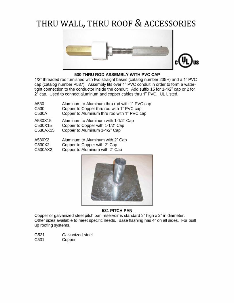
530 THRU ROD ASSEMBLY WITH PVC CAP 1/2” threaded rod furnished with two straight bases (catalog number 235H) and a 1” PVC cap (catalog number P537). Assembly fits over 1” PVC conduit in order to form a water- tight connection to the conductor inside the conduit. Add suffix 15 for 1-1/2” cap or 2 for 2” cap. Used to connect aluminum and copper cables thru 1” PVC. UL Listed.
A530 Aluminum to Aluminum thru rod with 1” PVC cap C530 Copper to Copper thru rod with 1” PVC cap C530A Copper to Aluminum thru rod with 1” PVC cap
A530X15 Aluminum to Aluminum with 1-1/2” Cap C530X15 Copper to Copper with 1-1/2” Cap C530AX15 Copper to Aluminum 1-1/2” Cap
A530X2 Aluminum to Aluminum with 2” Cap C530X2 Copper to Copper with 2” Cap C530AX2 Copper to Aluminum with 2” Cap
531 PITCH PAN
Copper or galvanized steel pitch pan reservoir is standard 3” high x 2” in diameter. Other sizes available to meet specific needs. Base flashing has 4” on all sides. For built up roofing systems.
G531 Galvanized steel C531 Copper
THRU WALL, THRU ROOF & ACCESSORIES
P ref e r re d L ig h t n in g P ro t e ct i o n 86 6- 2 9 9- 7 40 6 o r 6 6 0 - 5 6 2- 2 7 7 1 21 0 0 E a s t F i rst St r e e t F a x: 6 6 0 - 5 82 - 2 6 0 3 M ar yv i l l e , M O 6 4 4 6 8 sa l es @ p r ef e r r ed lp . co m Is s
u e Da t e : J u n e 2 0 1 3 P ag e 80 w w w .p r ef e r r ed l p . c o m
P532 RUBBER BOOT Pipe flashing boot constructed of Ethylene Propylene Diene Monomer (EPDM). Use on single ply membrane roofs in conjunction with catalog numbers 533 and 534.
P532 EPDM Flashing Boot
533 FLASHING ADAPTOR 534 PIPE FLASHING CLAMP Flashing adaptor and clamp used to seal EPDM Flashing boot to thru-roof connectors. Adaptor is available in Aluminum and Brass and is 1” in diameter and 1” high. Furnished for 3/8”, 1/2”, and 5/8” thru-roofs. Specify when ordering.
P ref e r re d L ig h t n in g P ro t e ct i o n 86 6- 2 9 9- 7 40 6 o r 6 6 0 - 5 6 2- 2 7 7 1 21 0 0 E a s t F i rst St r e e t F a x: 6 6 0 - 5 82 - 2 6 0 3 M ar yv i l l e , M O 6 4 4 6 8 sa l es @ p r ef e r r ed lp . co m Is s
u e Da t e : J u n e 2 0 1 3 P ag e 81 w w w .p r ef e r r ed l p . c o m
P537 PVC CAP 1” PVC cap for use in sealing thru-roof penetrations with 1” PVC conduit.
P537 1” PVC Cap with 1/2” hole P537x15 1-1/2” PVC Cap with 1/2” hole P537x2 2” PVC Cap with 1/2” hole
540 FLASHING CONE
Cast flashing cone used to seal thru-roof penetrations. A540 Aluminum C540 Bronze
541 ROOF FLASHING SADDLE Stamped flashing saddle for use with concealed air terminals or thru-roof penetrations. Standard size is 2-1/2” x 4”. Other sizes can be fabricated. Please specify dimensions when ordering other than the standard size. UL Listed.
A541 Aluminum C541 Copper
THRU WALL, THRU ROOF & ACCESSORIES
P ref e r re d L ig h t n in g P ro t e ct i o n 86 6- 2 9 9- 7 40 6 o r 6 6 0 - 5 6 2- 2 7 7 1 21 0 0 E a s t F i rst St r e e t F a x: 6 6 0 - 5 82 - 2 6 0 3
M ar yv i l l e , M O 6 4 4 6 8 sa l es @ p r ef e r r ed lp . co m Is s
u e Da t e : J u n e 2 0 1 3 P ag e 8 2 w w w .p r ef e r r ed l p . c o m
S544 FLASHING WASHER
Stainless steel flashing washer with 9/16” center hole. 1/8” thick and 3”square.
S544 Flashing Washer
GROUNDING
P ref e r re d L ig h t n in g P ro t e ct i o n 86 6- 2 9 9- 7 40 6 o r 6 6 0 - 5 6 2- 2 7 7 1 21 0 0 E a s t F i rst St r e e t F a x: 6 6 0 - 5 82 - 2 6 0 3 M ar yv i l l e , M O 6 4 4 6 8 sa l es @ p r ef e r r ed lp . co m
Is s u e Da t e : J u n e 2 0 1 3 P ag e 8 3 w w w .p r ef e r r ed l p . c o m
CC600 1/2" x 8’ CC600S 1/2" x 8’ CC601 1/2" x 10’ CC601S 1/2" x 10’ CC603 5/8” x 8’ CC603S 5/8” x 8’ CC604 5/8” x 10’ CC604S 5/8” x 10’ CC607 3/4" X 10’ CC607S 3/4" X 10’
C600 1/2" x 8’ S600 1/2” x 8’ C601 1/2" x 10’ S601 1/2” x 10’ C603 5/8” x 8’ S603 5/8” x 8’ C604 5/8” x 10’ S604 5/8” x 10’ C607 3/4" X 10’ S607 3/4” x 10’
GROUND RODS
We offer Copperclad, solid Copper, Stainless Steel, and sectional ground rods in various lengths. CC represents Copperclad and C represents solid Copper. The suffix “S" represents sectional. UL Listed.
Copperclad aircraft tie down ground rods. Other sizes available upon request. See also CC607TD. UL Listed.
CC607A 3/4" x 9 1/2'
GROUNDING
P ref e r re d L ig h t n in g P ro t e ct i o n 86 6- 2 9 9- 7 40 6 o r 6 6 0 - 5 6 2- 2 7 7 1 21 0 0 E a s t F i rst St r e e t F a x: 6 6 0 - 5 82 - 2 6 0 3 M ar yv i l l e , M O 6 4 4 6 8 sa l es @ p r ef e r r ed lp . co m Is s u e Da t e : J u n e 2 0 1 3 P ag e 84 w w w .p r ef e r r ed l p . c o m
TIE DOWN AS SE MBL Y
Copper Clad Sectional Ground Rod complete with catalog no.C618 eyelet. Used to tie down aircraft or provide a static discharge point. Assembly provides easier installation of rod and eyelet screws onto top. UL Listed. A coupling and driving stud are needed to drive the ground rod but are not provided with this assembly. We suggest a coupling and driving stud, under normal conditions should last about 7 assemblies.
CC607TD 3/4" x 10’ ground rod with grounding eyelet.
GROUND ROD ASSEMBLY
Assembly consists of 2 sections 5’ long of ground rods and 1 threadless coupling. Eliminates oversize charges for shipping long ground rods. Available for both Copper Clad and stainless steel ground rods. UL Listed.
CC601KIT 1/2" Copper Clad ground rod kit CC604KIT 5/8” Copper Clad ground rod kit CC607KIT 3/4" Copper Clad ground rod kit S604KIT 5/8” Stainless Steel ground rod kit S607KIT 3/4” Stainless Steel ground rod kit
GROUNDING
P ref e r re d L ig h t n in g P ro t e ct i o n 86 6- 2 9 9- 7 40 6 o r 6 6 0 - 5 6 2- 2 7 7 1 21 0 0 E a s t F i rst St r e e t F a x: 6 6 0 - 5 82 - 2 6 0 3
M ar yv i l l e , M O 6 4 4 6 8 sa l es @ p r ef e r r ed lp . co m Is s
u e Da t e : J u n e 2 0 1 3 P ag e 85 w w w .p r ef e r r ed l p . c o m
ENHANCED GROUND RODS
Enhanced ground rods are used in high resistivity soils to provide a low resistance ground. Each kit includes an enhanced ground rod, inspection well, P628 ground enhancement material and a 4/0 Copper pigtail 4’ in length. Can be purchased for either vertical or horizontal installation. Standard sizes are shown below; contact our Sales Department for other sizes, options and pricing.
EGR 10V 4/0 10’ Vertical Enhanced Ground Rod EGR 20V 4/0 20’ Vertical Enhanced Ground Rod EGR 10H 4/0 10’ Horizontal Enhanced Ground Rod EGR 20H 4/0 20’ Horizontal Enhanced Ground Rod
CC610 HELIX DRIVING ANCHOR
Copper clad helix driving anchor, used to drive threaded tie down rods.
CC610X58 Helix driving anchor for 5/8” tie down rod CC610X34 Helix driving anchor for 3/4” tie down rod
GROUNDING
P ref e r re d L ig h t n in g P ro t e ct i o n 86 6- 2 9 9- 7 40 6 o r 6 6 0 - 5 6 2- 2 7 7 1 21 0 0 E a s t F i rst St r e e t F a x: 6 6 0 - 5 82 - 2 6 0 3
M ar yv i l l e , M O 6 4 4 6 8 sa l es @ p r ef e r r ed lp . co m Is s
u e Da t e : J u n e 2 0 1 3 P ag e 86 w w w .p r ef e r r ed l p . c o m
THREADED COUPLING Ground rod coupling used to connect sectional ground rods. Machined from tough Copper Alloy. UL Listed.
C611 1/2” Threaded coupling for full size rods C612 5/8” Threaded coupling for nominal rods C613 3/4” Threaded coupling for nominal rods
COMPRESSION COUPLING
Threadless ground rod coupling used to connect two pointed ground rods. The coupling is tapered so the parts compress, when driving the rod, to form a conductive connection. Allows for quick and easy installation. Available for copper bond or stainless steel ground rods. UL Listed.
C611CC 1/2” Compression coupling for full size rod C612CC 5/8” Compression coupling for nominal rods C613CC 3/4” Compression coupling for nominal rods
S612CC 5/8” Compression coupling for nominal rods S613CC 3/4” Compression coupling for nominal rods
GROUNDING
P ref e r re d L ig h t n in g P ro t e ct i o n 86 6- 2 9 9- 7 40 6 o r 6 6 0 - 5 6 2- 2 7 7 1 21 0 0 E a s t F i rst St r e e t F a x: 6 6 0 - 5 82 - 2 6 0 3 M ar yv i l l e , M O 6 4 4 6 8 sa l es @ p r ef e r r ed lp . co m
Is s u e Da t e : J u n e 2 0 1 3 P ag e 87 w w w .p r ef e r r ed l p . c o m
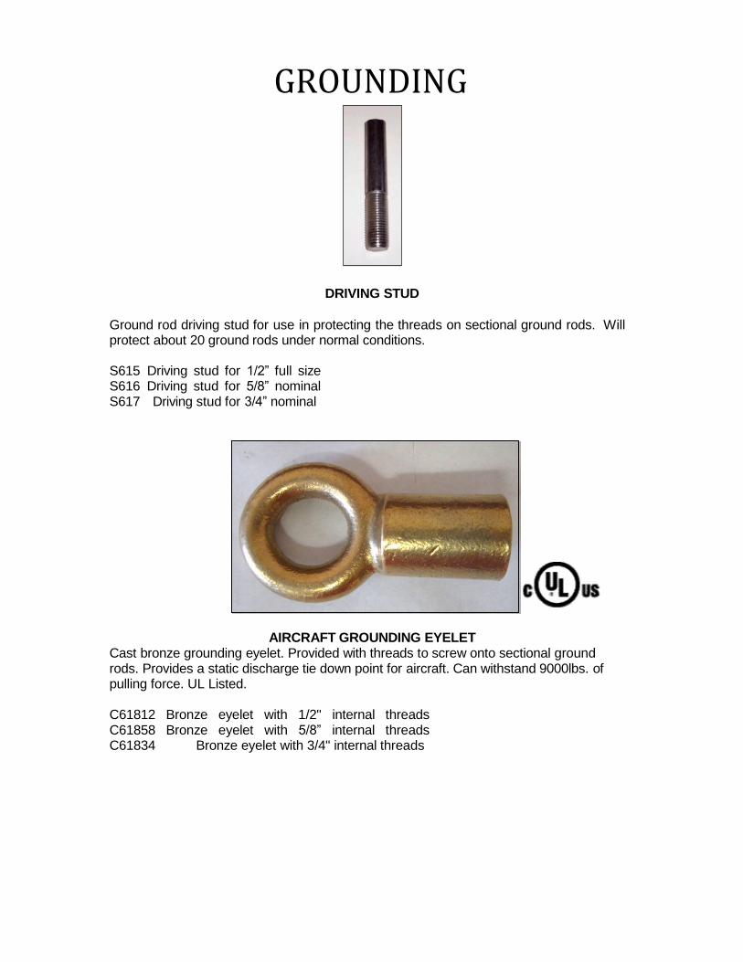
DRIVING STUD
Ground rod driving stud for use in protecting the threads on sectional ground rods. Will protect about 20 ground rods under normal conditions.
S615 Driving stud for 1/2” full size S616 Driving stud for 5/8” nominal S617 Driving stud for 3/4” nominal
AIRCRAFT GROUNDING EYELET Cast bronze grounding eyelet. Provided with threads to screw onto sectional ground rods. Provides a static discharge tie down point for aircraft. Can withstand 9000lbs. of pulling force. UL Listed.
C61812 Bronze eyelet with 1/2" internal threads C61858 Bronze eyelet with 5/8” internal threads C61834 Bronze eyelet with 3/4" internal threads
GROUNDING
P ref e r re d L ig h t n in g P ro t e ct i o n 86 6- 2 9 9- 7 40 6 o r 6 6 0 - 5 6 2- 2 7 7 1 21 0 0 E a s t F i rst St r e e t F a x: 6 6 0 - 5 82 - 2 6 0 3 M ar yv i l l e , M O 6 4 4 6 8 sa l es @ p r ef e r r ed lp . co m
Is s u e Da t e : J u n e 2 0 1 3 P ag e 8 8 w w w .p r ef e r r ed l p . c o m
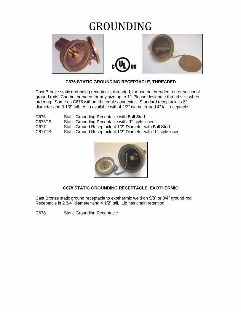
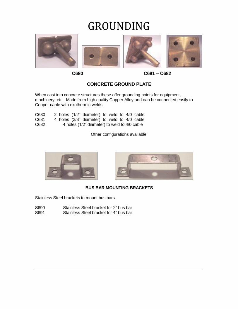
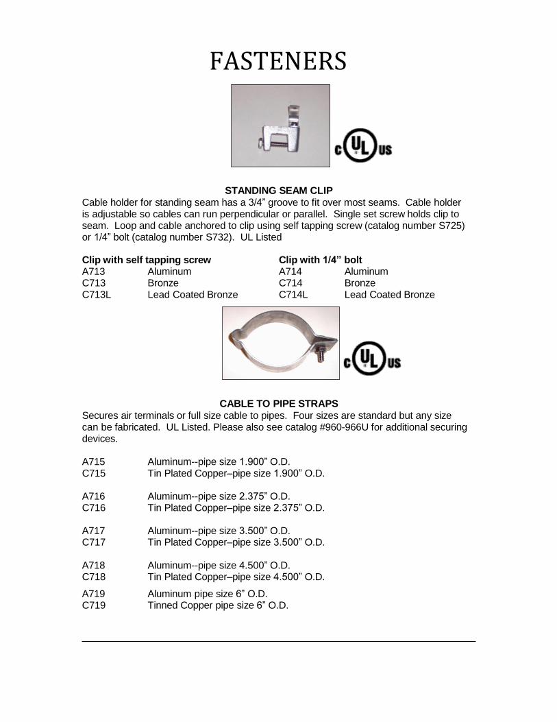
C619 12” X 12” (1 square foot)
C620 12” X 24” (2 square feet) C623 12” X 24” (2 square feet) C621 18” X 18” (2 1/3 square feet) C624 18” X 18” (2 1/3 square feet) C622 36” X 36” (9 square feet) C625 36” X 36” (9 square feet)
ONE CONNECTION GROUND PLATE TWO CONNECTION GROUND PLATE
.032 thick high conductivity Copper sheet with either one or two bonding plates (catalog number C410) attached to plate. Any size can be fabricated. UL Listed
One plate attached Two plates attached
CGP1236P 12”X36” Copper Plate with Bond Plate CGP24242P 24”X24” Copper Plate with Two Bonding Plates
Note: Both the top and bottom surfaces of the ground plate may be used to calculate the 2 square foot requirements for UL 96.
GROUNDPLATE WITH EXOTHERMIC WELD PIGTAIL
EXOTHERMIC WELD GROUND PLATES CGP181824C56-19 Copper 18” x 18” Ground Plate with 2’ of C56-19
(2/0-19) Bare Copper Cable ANY SIZE CAN BE FABRICATED
Description for ordering: CGP
Copper ground thickness plate (decimals)
width of p (inches)
late length of length o plate pigtail
f cable for pigtail (use cable section
(inches) (inches) for cable options)
GROUNDING
P ref e r re d L ig h t n in g P ro t e ct i o n 86 6- 2 9 9- 7 40 6 o r 6 6 0 - 5 6 2- 2 7 7 1 21 0 0 E a s t F i rst St r e e t F a x: 6 6 0 - 5 82 - 2 6 0 3 M ar yv i l l e , M O 6 4 4 6 8 sa l es @ p r ef e r r ed lp . co m Is s u e Da t e : J u n e 2 0 1 3 P ag e 8 9 w w w .p r ef e r r ed l p . c o m
P627 BENTONITE CLAY Western Bentonite Clay is a natural earth clay backfill material that improves the soil conditions for grounding. It absorbs water and moisture to lower ground resistance. Available in 50lb. bags.
P627 Bentonite Clay
P628 ELECTRODE BACKFILL MATERIAL
Low resistance carbon based backfill material. Lowers ground system resistance in difficult soil situations. Ideal for use in rocky soil, sand, gravel or any other high resistance soil conditions. Available 25lb. bags.
P628 Electrode Backfill Material
P629 TIE DOWN ROD DRIVER
Used to drive 3/4” tie down anchors (PLP Part # CC607A) without deforming the top eye loop.
P629 Driving head for CC607A
GROUNDING
P ref e r re d L ig h t n in g P ro t e ct i o n 86 6- 2 9 9- 7 40 6 o r 6 6 0 - 5 6 2- 2 7 7 1 21 0 0 E a s t F i rst St r e e t F a x: 6 6 0 - 5 82 - 2 6 0 3
M ar yv i l l e , M O 6 4 4 6 8 sa l es @ p r ef e r r ed lp . co m Is s
u e Da t e : J u n e 2 0 1 3 P ag e 9 9 w w w .p r ef e r r ed l p . c o m
C630 PROTECTOR PIPE
Copper tube 6’-8” long protector pipe. For use where cables are subject to displacement or damage on Class I structures only and with cables through 1/2” diameter. Use lead wedge to make electrically continuous with conductor. Secure to wall with catalog number C706L.
Copper tube 6’-8” long with set screw collars at both ends to bond pipe. 3/4” O.D. tube is used where cables are subject to displacement or damage. Secure with catalog number C707L.
C631 Copper Protector Pipe
PVC PROTECTOR PIPE
Polyvinylchloride (PVC) protector pipe-for use where cables are subject to displacement or damage. Schedule 40 and sunlight resistant. Secure with catalog number G706, C706LPVC, G707, or C707LPVC.
P631 P631-4
3/4” I.D. X 10’ 3/4” I.D. X 4’
P636 P636-4
1-1/2” I.D. X 10’ 1/1/2” I.D. X 4’
P632 P632-4
1” I.D. X 10’ 1” I.D. X 4’
P637 P637-4
2” I.D. X 10’ 2” I.D. X 4’
GROUNDING
P ref e r re d L ig h t n in g P ro t e ct i o n 86 6- 2 9 9- 7 40 6 o r 6 6 0 - 5 6 2- 2 7 7 1 21 0 0 E a s t F i rst St r e e t F a x: 6 6 0 - 5 82 - 2 6 0 3 M ar yv i l l e , M O 6 4 4 6 8 sa l es @ p r ef e r r ed lp . co m
Is s u e Da t e : J u n e 2 0 1 3 P ag e 9 1 w w w .p r ef e r r ed l p . c o m
P633 WOOD PROTECTOR
2” wide treated wood molding 8’ long protects cables that are subject to displacement or damage. For cables up to 3/4” diameter. Secure with catalog number G708.
P633 Wood protector
G634 GALVANIZED PROTECTOR
1” rigid galvanized conduit with PVC insert to protect cables that are subject to displacement or damage. Provided with 2 bonding screws. Available for all cable and secondary wire sizes. Secure with G707R.
G634 Galvanized protector with PVC insert 10’ long.
641-643 GROUND ROD CLAMPS
Cast Bronze ground rod clamp has 1-1/2” of contact and two bolt tension. Available for 1/2”, 5/8”, or 3/4” ground rods. UL Listed
C641 1/2” Ground Rod Clamp C642 5/8” Ground Rod Clamp C643 3/4” Ground Rod Clamp
GROUNDING
P ref e r re d L ig h t n in g P ro t e ct i o n 86 6- 2 9 9- 7 40 6 o r 6 6 0 - 5 6 2- 2 7 7 1 21 0 0 E a s t F i rst St r e e t F a x: 6 6 0 - 5 82 - 2 6 0 3 M ar yv i l l e , M O 6 4 4 6 8 sa l es @ p r ef e r r ed lp . co m
Is s u e Da t e : J u n e 2 0 1 3 P ag e 9 2 w w w .p r ef e r r ed l p . c o m
C645 U-BOLT GROUND ROD CLAMP
Cast U-Bolt bonding clamp for use with pipe or round bar from .400” to 1.315” Can be used with cable and wire sizes from #6 to 250 MCM. UL Listed
C645 U-Bolt Ground Rod Clamp C645L U-Bolt Ground Rod Clamp Leaded
P648 DEPRESSION FORM
Plastic form, 3” x 6” x 3” deep, to pour concrete around aircraft tie-down anchor (catalog number CC607A).
P648 Depression Form
GROUNDING
P ref e r re d L ig h t n in g P ro t e ct i o n 86 6- 2 9 9- 7 40 6 o r 6 6 0 - 5 6 2- 2 7 7 1 21 0 0 E a s t F i rst St r e e t F a x: 6 6 0 - 5 82 - 2 6 0 3 M ar yv i l l e , M O 6 4 4 6 8 sa l es @ p r ef e r r ed lp . co m
Is s u e Da t e : J u n e 2 0 1 3 P ag e 9 3 w w w .p r ef e r r ed l p . c o m
PVC GROUND ACCESS WELL
PVC ground access well with 10”or 12” ID diameter. Galvanized steel lid included.
10” diameter 12” diameter
P649 P650 P651 P652
12” long 18” long 24” long 36” long
P657
P654 P655 P656 36” long
12” long 18” long 24” long
GALVANIZED STEEL LID
For use with 10” or 12” PVC ground well.
P659 10” Lid P660 12” Lid
GROUNDING
P ref e r re d L ig h t n in g P ro t e ct i o n 86 6- 2 9 9- 7 40 6 o r 6 6 0 - 5 6 2- 2 7 7 1 21 0 0 E a s t F i rst St r e e t F a x: 6 6 0 - 5 82 - 2 6 0 3 M ar yv i l l e , M O 6 4 4 6 8 sa l es @ p r ef e r r ed lp . co m Is s u e Da t e : J u n e 2 0 1 3 P ag e 94 w w w .p r ef e r r ed l p . c o m
LEAD WEDGE
Lead wedge used to make conductor electrically continuous with metallic protector at entrance and exit points.
P661 Use with 1/2” ID Pipe P662 Use with 5/8” ID Pipe P663 Use with 3/4” ID Pipe P664 Use with 1” ID Pipe
DRIVING SLEEVE
Steel ground rod driving sleeve to prevent mushrooming on top of ground rod. Made from heat-treated, stress-proof steel. P670 For 1/2” Ground Rod P671 For 5/8” Ground Rod P672 For 3/4” Ground Rod
REBAR BONDING ASSEMBLY
Prefabricated Rebar Bonding Assembly with a 5’ piece of Copper Conductor, Exothermic Welded to an 18” long piece of #4 Rebar. Rebar can be welded or tied to construction steel to form bond. UL Listed. C673xC52 Rebar with C52 cable (Class I System) C673xC56 Rebar with C56 cable (Class II System) C673xC59 Rebar with C59 (4/O) cable
GROUNDING
P ref e r re d L ig h t n in g P ro t e ct i o n 86 6- 2 9 9- 7 40 6 o r 6 6 0 - 5 6 2- 2 7 7 1 21 0 0 E a s t F i rst St r e e t F a x: 6 6 0 - 5 82 - 2 6 0 3
M ar yv i l l e , M O 6 4 4 6 8 sa l es @ p r ef e r r ed lp . co m Is s
u e Da t e : J u n e 2 0 1 3 P ag e 95 w w w .p r ef e r r ed l p . c o m
REPLACEMENT STUDS, INSERTS AND CHAINS
Brass inserts for Static Ground Receptacles. Used as replacements or mounted to bus bars. Also available is the lid retention chain.
C674x12 Ball Stud with 1/2” Threads C674CHAIN Chain replacement for lid
C674x38TS “T” Style insert with 3/8” Threads C674x12TS “T” Style insert with 1/2” Threads C674x58TS “T” Style insert with 5/8” Threads
675 STATIC GROUND RECEPTACLE, THREADED, WITH CABLE CONNECTOR
Cast Brass Static Ground Receptacle with either rounded ball stud or “T” style insert. Cover plate has chain retention. Designed to couple onto threaded rod or ground rod. Comes with a cable connector for attaching ground cables. Can be threaded for any size up to 1”. Please designate thread size when ordering. Receptacle is 3” diameter and 3 1/2” tall. UL Listed.
C675 Brass Ground Receptacle with Ball Stud and cable connector C675TS Brass Ground Receptacle with “T” Style insert and cable connector
GROUNDING
P ref e r re d L ig h t n in g P ro t e ct i o n 86 6- 2 9 9- 7 40 6 o r 6 6 0 - 5 6 2- 2 7 7 1 21 0 0 E a s t F i rst St r e e t F a x: 6 6 0 - 5 82 - 2 6 0 3
M ar yv i l l e , M O 6 4 4 6 8 sa l es @ p r ef e r r ed lp . co m Is s
u e Da t e : J u n e 2 0 1 3 P ag e 96 w w w .p r ef e r r ed l p . c o m
C676 STATIC GROUNDING RECEPTACLE, THREADED Cast Bronze static grounding receptacle, threaded, for use on threaded rod or sectional ground rods. Can be threaded for any size up to 1”. Please designate thread size when ordering. Same as C675 without the cable connector. Standard receptacle is 3” diameter and 3 1/2” tall. Also available with 4 1/2” diameter and 4” tall receptacle.
C676 Static Grounding Receptacle with Ball Stud C676TS Static Grounding Receptacle with “T” style insert C677 Static Ground Receptacle 4 1/2” Diameter with Ball Stud C677TS Static Ground Receptacle 4 1/2” Diameter with “T” style insert
C678 STATIC GROUNDING RECEPTACLE, EXOTHERMIC
Cast Bronze static ground receptacle to exothermic weld on 5/8” or 3/4” ground rod. Receptacle is 2 3/4” diameter and 4 1/2” tall. Lid has chain retention.
C678 Static Grounding Receptacle
GROUNDING
P ref e r re d L ig h t n in g P ro t e ct i o n 86 6- 2 9 9- 7 40 6 o r 6 6 0 - 5 6 2- 2 7 7 1 21 0 0 E a s t F i rst St r e e t F a x: 6 6 0 - 5 82 - 2 6 0 3
M ar yv i l l e , M O 6 4 4 6 8 sa l es @ p r ef e r r ed lp . co m Is s
u e Da t e : J u n e 2 0 1 3 P ag e 97 w w w .p r ef e r r ed l p . c o m
C680 C681 – C682
CONCRETE GROUND PLATE When cast into concrete structures these offer grounding points for equipment, machinery, etc. Made from high quality Copper Alloy and can be connected easily to Copper cable with exothermic welds.
C680 2 holes (1/2” diameter) to weld to 4/0 cable C681 4 holes (3/8” diameter) to weld to 4/0 cable C682 4 holes (1/2” diameter) to weld to 4/0 cable
Other configurations available.
BUS BAR MOUNTING BRACKETS
Stainless Steel brackets to mount bus bars.
S690 Stainless Steel bracket for 2” bus bar S691 Stainless Steel bracket for 4” bus bar
GROUNDING
P ref e r re d L ig h t n in g P ro t e ct i o n 86 6- 2 9 9- 7 40 6 o r 6 6 0 - 5 6 2- 2 7 7 1 21 0 0 E a s t F i rst St r e e t F a x: 6 6 0 - 5 82 - 2 6 0 3
M ar yv i l l e , M O 6 4 4 6 8 sa l es @ p r ef e r r ed lp . co m Is s
u e Da t e : J u n e 2 0 1 3 P ag e 98 w w w .p r ef e r r ed l p . c o m
STAND OFF INSULATOR
Standoff insulator, manufactured from fiberglass. Two sizes available.
P695 Red Insulator – 1-1/2” length with 5/16” threaded holes P696 Red Insulator – 2” length with 3/8” threaded holes
GROUNDING AND BUS BARS Many different options are available for our bus bar grounding products. Please contact our Sales Department for more information on whole configurations, sizes, and options. All bus bar components can be purchased individually or as a kit. UL Listed 96.
FASTENERS
P ref e r re d L ig h t n in g P ro t e ct i o n 86 6- 2 9 9- 7 40 6 o r 6 6 0 - 5 6 2- 2 7 7 1 21 0 0 E a s t F i rst St r e e t F a x: 6 6 0 - 5 82 - 2 6 0 3 M ar yv i l l e , M O 6 4 4 6 8 sa l es @ p r ef e r r ed lp . co m Is s
u e Da t e : J u n e 2 0 1 3 P ag e 9 9 w w w .p r ef e r r ed l p . c o m
702 LOOP 1/2” wide loop–secure with a single nail or screw. For use with all Class I cables or secondary bonding wires. UL Listed
A702 Aluminum C702 Copper C702L Lead Coated Copper
703 LOOP
1/2” wide loop with two holes–secure with nails or screws. For use with all Class I cables or secondary bonding wires. UL Listed
A703 Aluminum C703 Copper C703L Lead Coated Copper
FASTENERS
P ref e r re d L ig h t n in g P ro t e ct i o n 86 6- 2 9 9- 7 40 6 o r 6 6 0 - 5 6 2- 2 7 7 1 21 0 0 E a s t F i rst St r e e t F a x: 6 6 0 - 5 82 - 2 6 0 3 M ar yv i l l e , M O 6 4 4 6 8 sa l es @ p r ef e r r ed lp . co m Is s
u e Da t e : J u n e 2 0 1 3 P ag e 1 0 0 w w w .p r ef e r r ed l p . c o m
704 LOOP 5/8” wide loop–secure with a single nail, screw, 1/4” bolt, or 1/4” drive-in anchor. For use with all cables or secondary bonding wires. UL Listed
A704 Aluminum A704x3/8 Aluminum with 3/8” holes C704 Copper C704L Lead Coated Copper C704x3/8 Copper with 3/8” holes C704x3/8L Lead Coated Copper with 3/8” holes
705 LOOP
5/8” wide loop with two holes–secure with nails, screws, 1/4” bolts, or 1/4” drive-in anchors. For use with all cables or secondary bonding wires. UL Listed
A705 Aluminum C705 Copper C705L Lead Coated Copper
FASTENERS
P ref e r re d L ig h t n in g P ro t e ct i o n 86 6- 2 9 9- 7 40 6 o r 6 6 0 - 5 6 2- 2 7 7 1 21 0 0 E a s t F i rst St r e e t F a x: 6 6 0 - 5 82 - 2 6 0 3 M ar yv i l l e , M O 6 4 4 6 8 sa l es @ p r ef e r r ed lp . co m Is s
u e Da t e : J u n e 2 0 1 3 Pa g e 101 w w w .p r ef e r r ed l p . c o m
C706 - C707 PROTECTOR PIPE STRAP
Tinned Copper strap with one fastening hole. Used to secure catalog numbers C630, C631, OR P631protector pipes. C706 fits pipe up to 3/4" O.D. and C707 fits pipe up to 1” O.D. UL Listed
C706L Tinned Copper Strap for use on C630 up to 3/4” O.D. C707L Tinned Copper Strap for use on C631 up to 1” O.D.
C706LPVC Tinned Copper Strap for use on 3/4” PVC up to 1” O.D. C707LPVC Tinned Copper Strap for use on 1” PVC up to 1-1/4” O.D
G706 – G707 PROTECTOR PIPE STRAP
Galvanized EMT 1-hole strap. Used to secure catalog numbers P631 and P632 protector pipes. G706 fits pipes up to 3/4” I.D. And G707 fits pipes up to 1” O.D.
Galvanized steel strap used for securing catalog number P633 wood protector. Provided with two 5/16” mounting holes.
G708 Galvanized steel strap
FASTENERS
P ref e r re d L ig h t n in g P ro t e ct i o n 86 6- 2 9 9- 7 40 6 o r 6 6 0 - 5 6 2- 2 7 7 1 21 0 0 E a s t F i rst St r e e t F a x: 6 6 0 - 5 82 - 2 6 0 3 M ar yv i l l e , M O 6 4 4 6 8 sa l es @ p r ef e r r ed lp . co m Is s
u e Da t e : J u n e 2 0 1 3 Pa g e 102 w w w .p r ef e r r ed l p . c o m
709 ADHESIVE STAND-OFF CABLE HOLDER Adhesive stand-off cable holder is comprised of a flat base (catalog number 252), 1/2” threaded rod (catalog number A75, C75 or S75) and a threaded rod clamp (catalog number 500). Designed to assist in maintaining the 3:12 rise between the roof surface and thru-rod connections or top of parapet. UL Listed
A709-6 Aluminum 6” length C709-6 Copper 6” length
C709-6L Lead Coated Copper 6” length A709 Aluminum 12” length C709 Copper 12” length C709L Lead Coated Copper 12” length
710 STAND-OFF CABLE HOLDER
Cast stand-off cable holder. Has up to 1-1/2” standoff with 1/2” threads. UL Listed
A710 Aluminum C710 Bronze C710L Lead Coated Bronze
FASTENERS
P ref e r re d L ig h t n in g P ro t e ct i o n 86 6- 2 9 9- 7 40 6 o r 6 6 0 - 5 6 2- 2 7 7 1 21 0 0 E a s t F i rst St r e e t F a x: 6 6 0 - 5 82 - 2 6 0 3 M ar yv i l l e , M O 6 4 4 6 8 sa l es @ p r ef e r r ed lp . co m Is s
u e Da t e : J u n e 2 0 1 3 Pa g e 103 w w w .p r ef e r r ed l p . c o m
711 CAST ADHESIVE CABLE HOLDER
Cast adhesive cable holder with bolt tension cable clip. For use with all full and secondary cables. UL Listed
A711 Aluminum C711 Bronze C711L Lead Coated Brass
712 STAMPED ADHESIVE CLIP Stamped adhesive cable clip with three compression type fingers to hold the cable securely to the roof. Middle finger stamped so the adhesive does not interfere with the anchoring process. For use with all main size cables and secondary bonding wires. UL Listed.
A712 Aluminum C712 Brass C712L Lead Coated Brass C712C Copper
FASTENERS
P ref e r re d L ig h t n in g P ro t e ct i o n 86 6- 2 9 9- 7 40 6 o r 6 6 0 - 5 6 2- 2 7 7 1 21 0 0 E a s t F i rst St r e e t F a x: 6 6 0 - 5 82 - 2 6 0 3 M ar yv i l l e , M O 6 4 4 6 8 sa l es @ p r ef e r r ed lp . co m Is s
u e Da t e : J u n e 2 0 1 3 Pa g e 104 w w w .p r ef e r r ed l p . c o m
STANDING SEAM CLIP
Cable holder for standing seam has a 3/4” groove to fit over most seams. Cable holder is adjustable so cables can run perpendicular or parallel. Single set screw holds clip to seam. Loop and cable anchored to clip using self tapping screw (catalog number S725) or 1/4” bolt (catalog number S732). UL Listed
Clip with self tapping screw Clip with 1/4” bolt A713 Aluminum A714 Aluminum C713 Bronze C714 Bronze C713L Lead Coated Bronze C714L Lead Coated Bronze
CABLE TO PIPE STRAPS
Secures air terminals or full size cable to pipes. Four sizes are standard but any size can be fabricated. UL Listed. Please also see catalog #960-966U for additional securing devices.
P ref e r re d L ig h t n in g P ro t e ct i o n 86 6- 2 9 9- 7 40 6 o r 6 6 0 - 5 6 2- 2 7 7 1 21 0 0 E a s t F i rst St r e e t F a x: 6 6 0 - 5 82 - 2 6 0 3
M ar yv i l l e , M O 6 4 4 6 8 sa l es @ p r ef e r r ed lp . co m Is s
u e Da t e : J u n e 2 0 1 3 Pa g e 105 w w w .p r ef e r r ed l p . c o m
P720 RUBBER WELL NUT
P720 1/4” X 1” Rubber well nut
STAINLESS STEEL AND COPPER NAILS C722 2” Copper Roofing Nail S721 4d Stainless Steel ring shank nail – 1-1/2” length S722 6d Stainless Steel ring shank nail – 2” length S723 8d Stainless Steel ring shank nail – 2-1/2” length
STAINLESS STEEL NEEDLE POINT SCREW
S727NP #10 X 1-1/2” Needle point screw with 1/4” head
STAINLESS STEEL SELF DRILLING SCREW S724 #10 X 3/4” Self drilling screw S725 #10 X 1” Self drilling screw S726 #10 X 1-1/4” Self drilling screw S727 #10 X 1-1/2” Self drilling screw S728 #10 X 2” Self drilling screw S728X3 #12 X 3” Self drilling screw
FASTENERS
P ref e r re d L ig h t n in g P ro t e ct i o n 86 6- 2 9 9- 7 40 6 o r 6 6 0 - 5 6 2- 2 7 7 1 21 0 0 E a s t F i rst St r e e t F a x: 6 6 0 - 5 82 - 2 6 0 3
M ar yv i l l e , M O 6 4 4 6 8 sa l es @ p r ef e r r ed lp . co m Is s
u e Da t e : J u n e 2 0 1 3 Pa g e 106 w w w .p r ef e r r ed l p . c o m
STAINLESS STEEL SELF DRILLING SCREW WITH NEOPRENE WASHER
S725W #10 x 1” Self drilling screw with neoprene washer S727W #10 x 1-1/2” Self drilling screw with neoprene washer S728 W #10 x 2” Self drilling screw with neoprene washer
P729 DRIVE-IN ANCHOR
P729 1/4” x 1-1/4” Zinc Drive-In Anchor S729x1 1/4” x 1” Stainless Steel Drive-In Anchor S729 1/4” x 1-1/4” Stainless Steel Drive-In Anchor
FLAT HEAD BOLT
S732F 1/4” x 1” S738F 5/16” x 1-1/4” S747F 1/2” x 3/4” S749F 1/2” x 1-1/2” S749x2F 1/2” x 2”
FASTENERS
P ref e r re d L ig h t n in g P ro t e ct i o n 86 6- 2 9 9- 7 40 6 o r 6 6 0 - 5 6 2- 2 7 7 1 21 0 0 E a s t F i rst St r e e t F a x: 6 6 0 - 5 82 - 2 6 0 3 M ar yv i l l e , M O 6 4 4 6 8 sa l es @ p r ef e r r ed lp . co m Is s u
e Da t e : J u n e 2 0 1 3 P ag e 1 0 7 w w w .p r ef e r r ed l p . c o m
STAINLESS STEEL BOLTS
SHB725 #10 X 1”
HEX HEAD BOLTS-FULL THREADS
S730 1/4” x 1/2” S737 5/16” x 1” S731 1/4” x 3/4” S738 5/16” x 1-1/4” S732 1/4” x 1” S739 5/16” x 1-1/2” S733 1/4” x 1-1/4” S740 5/16” x 2” S734 1/4” x 1-1/2” S741X58 3/8” x 5/8” S734x2 1/4” x 2” S741 3/8” x 3/4” S734x225 1/4” x 2-1/4” S742 3/8” x 1” S735 5/16” x 3/4” S743 3/8” x 1-1/4” S736 5/16” x 7/8” S745 3/8” x 2”
S747 1/2” x 3/4” S749X2 1/2" x 2”
CARRIAGE BOLTS SOCKET SET SCREWS
Stainless Steel
S739CB 5/16” x 1-3/4" S793 5/16” x 1/2” S794 5/16” x 3/4”
Brass
C793 5/16” x 1/2” C794 5/16” x 3/4”
FASTENERS
P ref e r re d L ig h t n in g P ro t e ct i o n 86 6- 2 9 9- 7 40 6 o r 6 6 0 - 5 6 2- 2 7 7 1 21 0 0 E a s t F i rst St r e e t F a x: 6 6 0 - 5 82 - 2 6 0 3 M ar yv i l l e , M O 6 4 4 6 8 sa l es @ p r ef e r r ed lp . co m Is s u
e Da t e : J u n e 2 0 1 3 P ag e 1 0 8 w w w .p r ef e r r ed l p . c o m
P ref e r re d L ig h t n in g P ro t e ct i o n 86 6- 2 9 9- 7 40 6 o r 6 6 0 - 5 6 2- 2 7 7 1 21 0 0 E a s t F i rst St r e e t F a x: 6 6 0 - 5 82 - 2 6 0 3 M ar yv i l l e , M O 6 4 4 6 8 sa l es @ p r ef e r r ed lp . co m Is s
u e Da t e : J u n e 2 0 1 3 P ag e 1 0 9 w w w .p r ef e r r ed l p . c o m
P776 1/4” Lead Expansion Anchor P778 3/8” Lead Expansion Anchor P779 1/2” Lead Expansion Anchor
FASTENERS
P ref e r re d L ig h t n in g P ro t e ct i o n 86 6- 2 9 9- 7 40 6 o r 6 6 0 - 5 6 2- 2 7 7 1 21 0 0 E a s t F i rst St r e e t F a x: 6 6 0 - 5 82 - 2 6 0 3
M ar yv i l l e , M O 6 4 4 6 8 sa l es @ p r ef e r r ed lp . co m Is s u e Da t e : J u n e 2 0 1 3 P ag e 1 1 0 w w w .p r ef e r r ed l p . c o m
EXPANSION ANCHOR SET TOOL
P776SET 1/4" Expansion Anchor Set Tool P778SET 3/8” Expansion Anchor Set Tool P779SET 1/2" Expansion Anchor Set Tool
P ref e r re d L ig h t n in g P ro t e ct i o n 86 6- 2 9 9- 7 40 6 o r 6 6 0 - 5 6 2- 2 7 7 1 21 0 0 E a s t F i rst St r e e t F a x: 6 6 0 - 5 82 - 2 6 0 3 M ar yv i l l e , M O 6 4 4 6 8 sa l es @ p r ef e r r ed lp . co m
Is s u e Da t e : J u n e 2 0 1 3 Pa g e 111 w w w .p r ef e r r ed l p . c o m
P780 SILICONE SEALANT
P780 100% silicone rubber sealant–10 oz tube.
P783 M-1
P783 M-1 Structural Adhesive/Sealant–10.1 oz tube.
P784-GREEN LOCK ADHESIVE
P784 Green Lock Structural Adhesive
Please indicate color for
M-1 Greenlock
with the following suffix:
AL-AlumGrey B- Black W-White
ADHESIVE
P ref e r re d L ig h t n in g P ro t e ct i o n 86 6- 2 9 9- 7 40 6 o r 6 6 0 - 5 6 2- 2 7 7 1 21 0 0 E a s t F i rst St r e e t F a x: 6 6 0 - 5 82 - 2 6 0 3 M ar yv i l l e , M O 6 4 4 6 8 sa l es @ p r ef e r r ed lp . co m Is s
u e Da t e : J u n e 2 0 1 3 Pa g e 112 w w w .p r ef e r r ed l p . c o m
P785-P786 POURABLE SEALER
A fast drying two part mix rubber adhesive for membrane roofing. Always verify compatibility of adhesive with roofing contractor and/or manufacturer. Sold by the gallon. Available from two manufacturers.
NOTE: Improper selection of adhesive may cause serious damage to the roof. Always verify adhesive materials with the roofing contractor and/or manufacturer.
P789 DURALINK
P789 Duralink Super Adhesion Sealant
ACCESSORIES
P ref e r re d L ig h t n in g P ro t e ct i o n 86 6- 2 9 9- 7 40 6 o r 6 6 0 - 5 6 2- 2 7 7 1 21 0 0 E a s t F i rst St r e e t F a x: 6 6 0 - 5 82 - 2 6 0 3 M ar yv i l l e , M O 6 4 4 6 8 sa l es @ p r ef e r r ed lp . co m Is s
u e Da t e : J u n e 2 0 1 3 Pa g e 113 w w w .p r ef e r r ed l p . c o m
P801 DECORATIVE GLASS BALLS
4-1/2” diameter decorative glass ball. Please designate color when ordering.
P801-Red Decorative Glass Ball Red P801-Blue Decorative Glass Ball Blue P801-Green Decorative Glass Ball Green P801-White Decorative Glass Ball White P801-Amber Decorative Glass Ball Amber
805 BUSHING
Bushing to secure decorative glass ball to air terminal.
A805 Aluminum C805 Copper
S807 CABLE SPOOLER
Steel frame to hold spool of cable.
S807 Cable Spooler
ACCESSORIES
P ref e r re d L ig h t n in g P ro t e ct i o n 86 6- 2 9 9- 7 40 6 o r 6 6 0 - 5 6 2- 2 7 7 1 21 0 0 E a s t F i rst St r e e t F a x: 6 6 0 - 5 82 - 2 6 0 3 M ar yv i l l e , M O 6 4 4 6 8 sa l es @ p r ef e r r ed lp . co m Is s
u e Da t e : J u n e 2 0 1 3 Pa g e 114 w w w .p r ef e r r ed l p . c o m
WEATHERVANES AVAILABLE:
P810 Dart Vane
P811 Horse Weathervane
P812 Cow Weathervane
ACCESSORIES
P ref e r re d L ig h t n in g P ro t e ct i o n 86 6- 2 9 9- 7 40 6 o r 6 6 0 - 5 6 2- 2 7 7 1 21 0 0 E a s t F i rst St r e e t F a x: 6 6 0 - 5 82 - 2 6 0 3 M ar yv i l l e , M O 6 4 4 6 8 sa l es @ p r ef e r r ed lp . co m Is s
u e Da t e : J u n e 2 0 1 3 Pa g e 115 w w w .p r ef e r r ed l p . c o m
P813 Bull Weathervane
P814 Pig Weathervane
P815 Rooster Weathervane
ACCESSORIES
P ref e r re d L ig h t n in g P ro t e ct i o n 86 6- 2 9 9- 7 40 6 o r 6 6 0 - 5 6 2- 2 7 7 1 21 0 0 E a s t F i rst St r e e t F a x: 6 6 0 - 5 82 - 2 6 0 3
M ar yv i l l e , M O 6 4 4 6 8 sa l es @ p r ef e r r ed lp . co m Is s
u e Da t e : J u n e 2 0 1 3 P ag e 1 1 6 w w w .p r ef e r r ed l p . c o m
DECORATIVE FINIALS
C820 16” Brass Finial C821 27” Decorative Finial
INDUSTRIAL STACK EQUIPMENT
P ref e r re d L ig h t n in g P ro t e ct i o n 86 6- 2 9 9- 7 40 6 o r 6 6 0 - 5 6 2- 2 7 7 1 21 0 0 E a s t F i rst St r e e t F a x: 6 6 0 - 5 82 - 2 6 0 3 M ar yv i l l e , M O 6 4 4 6 8 sa l es @ p r ef e r r ed lp . co m
Is s u e Da t e : J u n e 2 0 1 3 Pa g e 117 w w w .p r ef e r r ed l p . c o m
COPPER CABLES C901 Bare Copper Cable–(Same as C55) 28 strands of 14 gauge Bare Copper
wire. Rope lay cable–115,080 cm of conductivity. Weight per 1000’–380 lbs. UL Listed
C901LC Lead Covered Cable-28 strands of 14 gauge Bare Copper wire with
continuous 1/16” (1.59mm) pure lead sheath. Rope lay cable–115,080 cm of conductivity. Weight per 1000’–1,380 lbs. UL Listed
C902 4/0 AWG Bare Copper Cable-19 strands of .1055 Copper wire.
Concentric cable–211,600 cm of conductivity. Weight per 1000’–653 lbs. UL Listed
C902LC 4/0 AWG Lead Coated Copper Cable-19 strands of .1055 Copper wire
with continuous 1/16” (1.59mm) pure lead sheath. Concentric cable– 211,600 cm of conductivity. Weight per 1000’–1,983 lbs. UL Listed
INDUSTRIAL STACK EQUIPMENT
P ref e r re d L ig h t n in g P ro t e ct i o n 86 6- 2 9 9- 7 40 6 o r 6 6 0 - 5 6 2- 2 7 7 1 21 0 0 E a s t F i rst St r e e t F a x: 6 6 0 - 5 82 - 2 6 0 3 M ar yv i l l e , M O 6 4 4 6 8 sa l es @ p r ef e r r ed lp . co m Is s
u e Da t e : J u n e 2 0 1 3 Pa g e 118 w w w .p r ef e r r ed l p . c o m
AIR TERMINALS All Air Terminals are available in Stainless Steel, solid Copper, or solid Copper with 1/16” lead jacket. Air terminals can be ordered with a standard 2” taper or safety tipped. UL Listed. Available in any length greater than 18”. UL Listed.
DESCRIPTION FOR ORDERING
Prefix C -Designates Copper
Prefix S-Designates Stainless Steel
First Two Numbers-Designates Air Terminal Diameter
Second Two Numbers-Designates Air Terminal Length
Suffix LC-Designates Lead Coated
Suffix ST-Designates Safety Tipped
Example: C5824LC Copper 5/8”x24” Air Terminal with 1/16” Lead jacket
INDUSTRIAL STACK EQUIPMENT STACK BASES
P ref e r re d L ig h t n in g P ro t e ct i o n 86 6- 2 9 9- 7 40 6 o r 6 6 0 - 5 6 2- 2 7 7 1 21 0 0 E a s t F i rst St r e e t F a x: 6 6 0 - 5 82 - 2 6 0 3
M ar yv i l l e , M O 6 4 4 6 8 sa l es @ p r ef e r r ed lp . co m Is s
u e Da t e : J u n e 2 0 1 3 P ag e 11 9 w w w .p r ef e r r ed l p . c o m
SIDE-MOUNT STACK BASE WITH HORIZONTAL CABLE CONNECTION
Heavy duty Brass casting for use with 5/8” or 3/4” air terminal to horizontal cable run. Optional 1/2” bolt with 7/8” or 1-1/2” threads for connection to anchor. Accepts Class II or 4/0 cables. Please specify size when ordering 5/8” or 3/4”. UL Listed
No mounting hardware provided.
C910 Heavy Duty Brass--no Anchor Bolt C910LC Lead Covered Heavy Duty Brass--no Anchor Bolt
Provided with 1/2” mounting stud
C911 Heavy Duty Brass with 7/8” stud and P940 lead anchor C911LC Lead Covered Brass with 7/8” stud length and P940 lead anchor C911 LG Heavy Duty Brass with 1-1/2” stud length C911LCLG Lead Covered Heavy Duty Brass with 1-1/2” stud length
INDUSTRIAL STACK EQUIPMENT STACK BASES
P ref e r re d L ig h t n in g P ro t e ct i o n 86 6- 2 9 9- 7 40 6 o r 6 6 0 - 5 6 2- 2 7 7 1 21 0 0 E a s t F i rst St r e e t F a x: 6 6 0 - 5 82 - 2 6 0 3
M ar yv i l l e , M O 6 4 4 6 8 sa l es @ p r ef e r r ed lp . co m Is s
u e Da t e : J u n e 2 0 1 3 P ag e 12 0 w w w .p r ef e r r ed l p . c o m
SIDE-MOUNT FOUR-WAY STACK BASE
Heavy duty brass casting for use with 5/8” or 3/4” air terminal to a horizontal cable run and a vertical cable run. Optional 1/2” bolt with 7/8” or 1-1/2” threads for connection to anchor. Accepts Class II or 4/0 cables. Please specify size when ordering 5/8” or 3/4”. UL Listed
No mounting hardware provided.
C912 Heavy Duty Brass--no Anchor Bolt C912LC Lead Covered Heavy Duty Brass--no Anchor Bolt
Provided with 1/2” mounting stud.
C913 Heavy Duty Brass 7/8” stud and P940 lead anchor C913LC Lead Covered Brass with 7/8” stud length and P940 lead anchor C913LG Heavy Duty Brass with 1-1/2” stud length C913LCLG Lead Covered Heavy Duty Brass with 1-1/2” stud length
INDUSTRIAL STACK EQUIPMENT STACK BASES
P ref e r re d L ig h t n in g P ro t e ct i o n 86 6- 2 9 9- 7 40 6 o r 6 6 0 - 5 6 2- 2 7 7 1 21 0 0 E a s t F i rst St r e e t F a x: 6 6 0 - 5 82 - 2 6 0 3 M ar yv i l l e , M O 6 4 4 6 8 sa l es @ p r ef e r r ed lp . co m Is s
u e Da t e : J u n e 2 0 1 3 Pa g e 121 w w w .p r ef e r r ed l p . c o m
TOP MOUNT BASE
Heavy duty brass casting for use with 5/8” or 3/4” air terminal to a horizontal cable run. Optional 1/2” bolt with 7/8” or 1-1/2” threads for connection to anchor. Accepts Class II or 4/0 cables. Please specify size when ordering 5/8” or 3/4”. UL Listed
No mounting hardware provided.
C916 Heavy Duty Brass C916 LC Lead Covered Heavy Duty Brass
Provided with 1/2” mounting stud.
C917 Heavy Duty Brass 7/8” stud and P940 lead anchor C917LC Lead Covered Brass with 7/8” stud length and P940 lead anchor C917LG Heavy Duty Brass with 1-1/2” stud length C917LCLG Lead Covered Heavy Duty Brass with 1-1/2” stud length
INDUSTRIAL STACK EQUIPMENT
P ref e r re d L ig h t n in g P ro t e ct i o n 86 6- 2 9 9- 7 40 6 o r 6 6 0 - 5 6 2- 2 7 7 1 21 0 0 E a s t F i rst St r e e t F a x: 6 6 0 - 5 82 - 2 6 0 3 M ar yv i l l e , M O 6 4 4 6 8 sa l es @ p r ef e r r ed lp . co m Is s
u e Da t e : J u n e 2 0 1 3 Pa g e 122 w w w .p r ef e r r ed l p . c o m
CABLE SPLICERS
PARALLEL CABLE SPLICER
Heavy duty Brass parallel cable splicer with 3” of contact. For use with Class II or 4/0 cables. UL Listed
C921 Heavy Duty Brass C921 – LC Lead Covered Heavy Duty Brass
STRAIGHT CABLE SPLICER
Heavy duty brass straight cable splicer. For use with Class II or 4/0 cables. UL Listed C923 Heavy Duty Brass C923 – LC Lead Covered Heavy Duty Brass
CROSS RUN SPLICER
Heavy duty brass cross run splicer. For use with Class II or 4/0 cables. UL Listed C924 Heavy Duty Brass C924LC Lead Covered Heavy Duty Brass
INDUSTRIAL STACK EQUIPMENT
P ref e r re d L ig h t n in g P ro t e ct i o n 86 6- 2 9 9- 7 40 6 o r 6 6 0 - 5 6 2- 2 7 7 1 21 0 0 E a s t F i rst St r e e t F a x: 6 6 0 - 5 82 - 2 6 0 3
M ar yv i l l e , M O 6 4 4 6 8 sa l es @ p r ef e r r ed lp . co m Is s
u e Da t e : J u n e 2 0 1 3 Pa g e 123 w w w .p r ef e r r ed l p . c o m
“T” SPLICER
Heavy duty brass “T” splicer. For use with Class II or 4/0 cables. UL Listed. C925 Heavy Duty Brass C925LC Lead Covered Heavy Duty Brass
926 AIR TERMINAL CONNECTOR
Used to connect lead covered cables to an air terminal or small round metal surface. Available for 5/8”, 3/4”, or 7/8” O.D. Rods. UL Listed.
C92658LC Lead Covered Connector for 5/8” O.D. C92634LC Lead Covered Connector for 3/4" O.D. C92678LC Lead Covered Connector for 7/8” O.D.
INDUSTRIAL STACK EQUIPMENT
P ref e r re d L ig h t n in g P ro t e ct i o n 86 6- 2 9 9- 7 40 6 o r 6 6 0 - 5 6 2- 2 7 7 1 21 0 0 E a s t F i rst St r e e t F a x: 6 6 0 - 5 82 - 2 6 0 3
M ar yv i l l e , M O 6 4 4 6 8 sa l es @ p r ef e r r ed lp . co m Is s
u e Da t e : J u n e 2 0 1 3 Pa g e 124 w w w .p r ef e r r ed l p . c o m
BONDING LUGS
BONDING LUG
Bonding lug (eye connector) for use with Class II or 4/0 cables. UL Listed
C927 Brass for use with Class II cable
C927LC Lead Covered Brass for use with Class II cable C927LG Brass for use with 4/0 cable C927LCLG Lead Covered Brass for use with 4/0 cable
8” SQUARE INCH BONDING PLATE WITH WELDING PLATE
1/4” X 5” X 5” Steel plate is welded to stack to provide area for grounding. Provided with heavy duty brass cap for attaching Class II or 4/0 cables.
C928LC Steel Plate with heavy duty brass cap
INDUSTRIAL STACK EQUIPMENT
P ref e r re d L ig h t n in g P ro t e ct i o n 86 6- 2 9 9- 7 40 6 o r 6 6 0 - 5 6 2- 2 7 7 1 21 0 0 E a s t F i rst St r e e t F a x: 6 6 0 - 5 82 - 2 6 0 3
M ar yv i l l e , M O 6 4 4 6 8 sa l es @ p r ef e r r ed lp . co m Is s
u e Da t e : J u n e 2 0 1 3 Pa g e 125 w w w .p r ef e r r ed l p . c o m
2-BOLT CAP FASTENER FOR AIR TERMINAL OR CABLE
Use to secure Air Terminal or conductors and provided with 1/2” threaded stud either 7/8” or 1-1/2” long. Use catalog number P940 (lead anchor) for mounting (not provided). UL Listed.
C93212 Use with bare C901 or C902 Cables C93234LC Use with C901LC lead covered cable and lead covered 5/8” Air Terminal C93278LC Use with lead covered C902LC cable and 3/4” lead covered Air Terminal
934–PINCH TYPE CABLE FASTENER
For use with Class II or 4/0 cables. Provided with 1/2” threaded stud for anchoring. Available with 7/8” threaded stud. Use catalog number P940 (Lead Anchor) for mounting (not provided). UL Listed
C934 Bare Brass C934 – LC Lead Covered Brass
INDUSTRIAL STACK EQUIPMENT
P ref e r re d L ig h t n in g P ro t e ct i o n 86 6- 2 9 9- 7 40 6 o r 6 6 0 - 5 6 2- 2 7 7 1 21 0 0 E a s t F i rst St r e e t F a x: 6 6 0 - 5 82 - 2 6 0 3 M ar yv i l l e , M O 6 4 4 6 8 sa l es @ p r ef e r r ed lp . co m Is s
u e Da t e : J u n e 2 0 1 3 P ag e 1 2 6 w w w .p r ef e r r ed l p . c o m
FASTENERS
940–1/2” Expansion Shield
1/2” expansion shield with 1/2-13 internal thread. For use with 7/8” stud length products. UL Listed
P940 Expansion Shield
2 HOLE ANCHOR STRAP
Copper or stainless steel 2 hole anchor strap. Sized to fit the O.D. of air terminals or cable. Will accommodate either bare or lead covered materials. Stainless steel can be used on top 25’ of stack.
C960 C961 C962 C963 C964 C965 C966
Copper strap for 1/2" O.D. Copper strap for 9/16” O.D. Copper strap for 5/8” O.D. Copper strap for 11/16” O.D. Copper strap for 3/4" O.D. Copper strap for 13/16” O.D. Copper strap for 7/8” O.D
S960 S961 S962 S963 S964 S965 S966
Stainless steel strap for 1/2" O.D. Stainless steel strap for 9/16” O.D Stainless steel strap for 5/8” O.D. Stainless steel strap for 11/16” O.D. Stainless steel strap for 3/4” O.D. Stainless steel strap for 13/16” O.D. Stainless steel strap for 7/8” O.D.
INDUSTRIAL STACK EQUIPMENT
1U= O.D. range 0.400”-1.315” 2U= O.D. range 1.315”-2.000” 3U= O.D. range 1.900”-3.000” 4U= O.D. range 2.75”-4.500” 6U= O.D. range 4.500”-6.750” 8U= O.D. range 6.000”-8.625”
Material Code A-Aluminum C-Copper
Anchor Strap Size 960-966
See page 125
Pipe Size Range U-Bolt
see above
U-BOLT CABLE OR AIR TERMINAL TO PIPE SUPPORTS
Used to secure air terminals or full size cables to pipes. Made of 1/8 aluminum, copper, or stainless steel for heavy duty applications. For ordering please specify the 2 hole anchor strap size needed (please refer to catalog no. 960-966) followed by the U-bolt size needed (see below). UL Listed.
S-S tainless Steel
Example: S962-3U Stainless Steel strap with 5/8” O.D. support for a 3” O.D. range pipe
P ref e r re d L ig h t n in g P ro t e ct i o n 86 6- 2 9 9- 7 40 6 o r 6 6 0 - 5 6 2- 2 7 7 1 21 0 0 E a s t F i rst St r e e t F a x: 6 6 0 - 5 82 - 2 6 0 3 M ar yv i l l e , M O 6 4 4 6 8 s a l e s @ p r e f e r r e d l p . c o m Is s u e Da t e : J u n e 2 0 1 3 P ag e 1 2 7 w w w . p r e f e r r e d l p . c o m
SURGE PROTECTION
P ref e r re d L ig h t n in g P ro t e ct i o n 86 6- 2 9 9- 7 40 6 o r 6 6 0 - 5 6 2- 2 7 7 1 21 0 0 E a s t F i rst St r e e t F a x: 6 6 0 - 5 82 - 2 6 0 3 M ar yv i l l e , M O 6 4 4 6 8 sa l es @ p r ef e r r ed lp . co m
Is s u e Da t e : J u n e 2 0 1 3 P ag e 1 2 8 w w w .p r ef e r r ed l p . c o m
P775 RESIDENTIAL SURGE ARRESTER
Secondary surge arrester designed to protect against lightning surge damage. 120/240 VAC. Diagnostic LED light. For use in residential or light commercial installations. UL Listed but not rated for UL96A Installations
P775 Residential Surge Arrester
COMMERCIAL SURGE ARRESTORS
Preferred Lightning Protection offers a complete line of UL 1449 3rd Edition surge protection devices (SPD). We have SPD’s for residential, light commercial, or industrial.
We also have voice/dial signal protection devices and surge strips/UPS/Well Blocks available. Please call to discuss your specific needs.
COMPRESSION CONNECTORS
P ref e r re d L ig h t n in g P ro t e ct i o n 86 6- 2 9 9- 7 40 6 o r 6 6 0 - 5 6 2- 2 7 7 1 21 0 0 E a s t F i rst St r e e t F a x: 6 6 0 - 5 82 - 2 6 0 3 M ar yv i l l e , M O 6 4 4 6 8 sa l es @ p r ef e r r ed lp . co m Is s u e Da t e : J u n e 2 0 1 3 P ag e 12 9 w w w .p r ef e r r ed l p . c o m
YGL-C
An irreversible compression ground grid cross connector. Use on 6 connectors and 4 dies to install all combinations from #6 solid to 500 kcmil.
Catalog Cable to Cable Cable to Ground To Rebar
Element Number Element “A” Element “B” Element “A” Element “B”
1. Where a “U” or “PU” die is recommended with Y45 *These connectors can only be installed using the Y750, Y45, or Y46 HYPRESS™ HYPRESS™, a PT6515 adapter must be used. with the recommended dies. These connectors CANNOT be installed with the
2. Where a “U” or “PU” die is recommended with the Y35 and Y39 HYPRESS™ Y46 HYPRESS™, a PUADP-1 adapter must be used.
③ Polarized die for the PAT750-18V
COMPRESSION CONNECTORS
P ref e r re d L ig h t n in g P ro t e ct i o n 86 6- 2 9 9- 7 40 6 o r 6 6 0 - 5 6 2- 2 7 7 1 21 0 0 E a s t F i rst St r e e t F a x: 6 6 0 - 5 82 - 2 6 0 3 M ar yv i l l e , M O 6 4 4 6 8 sa l es @ p r ef e r r ed lp . co m Is s u e Da t e : J u n e 2 0 1 3 P ag e 13 0 w w w .p r ef e r r ed l p . c o m
YGHP-C An irreversible compression ground tap figure 6. Can be used as a tap.
Catalog Number
FIG.
No.
Accommodates
⑤
Cable to Rebar
B
Die Index No.
Installation Data
Y750/Y35 Y39
HYPRESS™
PAT750-
18V
③
Y45
HYPRESS™
④
Y46 HYPRESS™
No. of
Crimps Run Tap Run Tap
YGHP2C2 1 #6 Sol. (0.162)-- #2 Str. (0.292)
① #6 Sol. (0.162)-
-#2 Str. (0.292) -- --
.75
[19]
0 U0 U0 U0 U0 1
YGHP29C2 1
1/0 Str. (0.372)— 250 kcmil (0.575)
1/2"-5/8” Rod
#4 Sol. (0.204)--#2 (0.292)
#3 Rebar
3/8 Thru
½ $3 Rebar
#2 Str.
997
U997
⑦ U997P
U997
U997
1
YGHP29C26 1 1/0 Str. (0.372)-2/0 Str. (0.419) 1/0 Str.-2/0 Str.
YGHP29C29 ② 1 3/0 Str. (0.470)-
250 kcmil (0.575) 3/0 Str.-250
kcmil
YGHP34C2 ⑥ 1
5/8”-3/4” Rod
#4 Sol. (0.204)-#2 Str. (0.292)
#5 Rebar 5/8 Thru
3/4
--
998
PU998
PU998
PU998 or
S998
PU998 or
P998
1
YGHP34C26 ⑥ 1 1/0 Str. (0.372)-2/0 Str. (0.419) 1/0 Str.-2/0 Str.
YGHP34C29 ⑥
1 3/0 Str. (0.470)-
250 kcmil (0.575) 3/0 Str.-250
kcmil
① When using #6 SOL. In tap, fold conductor double ⑤ Clean rust and protective coatings from rebar before connector
To improve fill inYGHP2C2 installation to provide a proper ground connection. ② For YGHP29C29 when using 3/0 in tap, minimum Precrimping is not required.
Run conductor is 2/0 STR. ⑥ These connectors can only be installed using the Y750, Y45 or
③ Where a ‘U’ or ‘PO’ die is recommended with the Y45 Y46 HYPRESS™ with the recommended dies. These connectors can
HYPRESS™, a PT6515 adapter must be used. not be installed with the Y35 and Y39 HYPRESS™
④ Where a ‘U’ or ‘PU’ die is recommended with the Y45 ⑦Polarized die for the PAT750-18V
P ref e r re d L ig h t n in g P ro t e ct i o n 86 6- 2 9 9- 7 40 6 o r 6 6 0 - 5 6 2- 2 7 7 1 21 0 0 E a s t F i rst St r e e t F a x: 6 6 0 - 5 82 - 2 6 0 3 M ar yv i l l e , M O 6 4 4 6 8 sa l es @ p r ef e r r ed lp . co m Is s u e Da t e : J u n e 2 0 1 3 P ag e 1 3 1 w w w .p r ef e r r ed l p . c o m
YGHC-C An irreversible ground tap figure “C” connector. Used for all cables from #6 solid to 500 kcmil.
Catalog Data
Commercial Copper Cable Range/Ground Rod to Copper
P ref e r re d L ig h t n in g P ro t e ct i o n 86 6- 2 9 9- 7 40 6 o r 6 6 0 - 5 6 2- 2 7 7 1 21 0 0 E a s t F i rst St r e e t F a x: 6 6 0 - 5 82 - 2 6 0 3 M ar yv i l l e , M O 6 4 4 6 8 sa l es @ p r ef e r r ed lp . co m
Is s u e Da t e : J u n e 2 0 1 3 Pa g e 132 w w w .p r ef e r r ed l p . c o m
UDIEKITHYGRD
Catalog Number UC UO U997 Pu998 U1011 U1104 U1105 U2CABT (Ground rod pre-crimp die) PT29291 (Die Case)
UDIEKITCU, UDIEKITAL, UDIEKITHYGRD
COMPRESSION TOOLS
BURNDY® U Die Kits
Each UDIEKITCU and UDIEKITAL die kit includes 15 sets of “U” dies and the PT29291 die case. These stainless steel color coded dies are for crimping BURNDY® YA, YS, YA-A and YS-A type HYLUG™ color coded terminals and splices ranging from #6 AWG through 750 kcmil.
The UDIEKITHYGRD kit includes eight die sets. Seven die sets are used to install BURNDY® HYGROUND™ irreversible compression grounding connectors, and the U2CABT die set for pre-crimping 1/2”, 5/8” and 3/4” ground rods for increased rotational resistance.
BURNDY® “U” dies are used in the Y35, T39, Y750 series, PAT750-18V series, Y46, and PAT46-18V (with PUADP-1 adapter) tools.
UDIEKITCU Includes UDIEKITAL Includes Copper Wire Size Catalog Number Aluminum Wire Size Catalog Number
P ref e r re d L ig h t n in g P ro t e ct i o n 86 6- 2 9 9- 7 40 6 o r 6 6 0 - 5 6 2- 2 7 7 1 21 0 0 E a s t F i rst St r e e t F a x: 6 6 0 - 5 82 - 2 6 0 3 M ar yv i l l e , M O 6 4 4 6 8 sa l es @ p r ef e r r ed lp . co m
Is s u e Da t e : J u n e 2 0 1 3 Pa g e 133 w w w .p r ef e r r ed l p . c o m
PATRIOT® HIGH PERFORMANCE PAT750- LI
18 Volt Lithium-Ion Battery Actuated Tool
Hydraulic Self-Contained 12- Ton Crimping Tool
The BURNDY® PATRIOT®
PAT750-Lithium-Ion tool is approximately 25% faster than the previous models. In addition to faster crimp cycles, the High Performance PAT750-LI has newly designed electronics that are field proven for ultimate reliability and proven to handle the harshest work environments.
The PAT750-LI incorporates the latest engineering technology with a refined hydraulic system for ultra performance, speed and reliability. The redesigned field proven electronics provides the reliability in the harshest work environments. All BURNDY® battery actuated hydraulic tools provide a consistent, reliable connection every time. The PAT750-LI features the BURNDY® Y750 tool head, capable of using all “U” style dies, and incorporates a bearing and alignment guide for use on HYGROUND® and other asymmetrical connectors. The crimp head rotates 355°for operation in virtually any position.
Each PATRIOT® tool uses standard BURNDY® dies and off- the-shelf connectors available world-wide. Supplied with a durable high impact formed carrying case to hold the tool, battery charger, two 18 volt Lithium-Ion batteries, tool retention lanyard, and die compartment to hold “U” die sets. (Dies sold separately). Provided with a 5-year limited warranty. All PATRIOT® tools feature the BURNDY® INFINITY DRIVE® transmission which has a lifetime warranty.
Features and Benefits
Refined hydraulic system for ultra performance, speed and reliability.
Field proven electronics for ultimate reliability in the harshest environments.
Overmolded handle for comfort and improved grip; allows for one- handed operation for advance, retract, and hold.
18 volt Lithium-Ion batteries provide 2.5 times more charge/discharge cycles than traditional Ni-provide 430% more lifetime work.
30-minute charger controls current, voltage & temperature to maximize battery life. Forced air cooling fan cools the battery by forcing cool air through the battery’s built-in air vents.
State of the art crimping head design, 355° head rotation lets user get into tight areas easier.
Allows use of standard BURNDY® dies already in use.
P ref e r re d L ig h t n in g P ro t e ct i o n 86 6- 2 9 9- 7 40 6 o r 6 6 0 - 5 6 2- 2 7 7 1 21 0 0 E a s t F i rst St r e e t F a x: 6 6 0 - 5 82 - 2 6 0 3 M ar yv i l l e , M O 6 4 4 6 8 sa l es @ p r ef e r r ed lp . co m
Is s u e Da t e : J u n e 2 0 1 3 Pa g e 134 w w w .p r ef e r r ed l p . c o m
PATRIOT® HIGH PERFORMANCE PAT750XT-18V
Battery Actuated Tool
Hydraulic Self-Contained 12- Ton Crimping Tool
The BURNDY® PATRIOT® High Performance PAT750XT-18V tool is 25% faster than previous models. In addition to faster crimp cycles, the High Performance PAT750XT-18V has newly designed electronics that are field proven for ultimate reliability and proven to handle the harshest work environments.
The High Performance PAT750XT- 18V incorporates the latest engineering technology with a refined hydraulic system for ultra performance, speed and reliability. All PATRIOT® tools feature the BURNDY INFINITY DRIVE® transmission which has a lifetime warranty.
The High Performance PAT750XT- 18V features the BURNDY® Y750 tool head, capable of using all “U” style dies, and incorporates a bearing and alignment guide for use on HYGROUND® and other asymmetrical connectors. Features reliable head rotation design for operation in virtually any position. All PATRIOT® battery actuated hydraulic tools provide a consistent, reliable connection every time.
Each PATRIOT® tool uses standard BURNDY® dies and off- the-shelf connectors available world-wide. Supplied with a durable high impact formed carrying case to hold the tool, battery charger, two batteries, tool retention lanyard, and die compartment to hold “U” die sets. (Dies sold separately.) Provided with a 5-year limited warranty.
Features and Benefits
Refined hydraulic system for ultra
performance, speed and reliability.
Field proven electronics for ultimate reliability in the harshest environments.
True, one-handed operation for advance, retract, and hold
12 tons of output force for use on virtually all compression applications.
State of the art crimping head design, 360° head rotation lest user get into tight areas easier.
Allows use of standard BURNDY® dies already in use.
Ergonomically balanced tool design eases operation and helps lessen fatigue.
Durable high impact formed carrying case provides superior protection and stores all accessories.
PAT750CXT-18V-rubber covered head is available.
118 volt Ni-MH battery eliminates voltage depression (memory issues).
P ref e r re d L ig h t n in g P ro t e ct i o n 86 6- 2 9 9- 7 40 6 o r 6 6 0 - 5 6 2- 2 7 7 1 21 0 0 E a s t F i rst St r e e t F a x: 6 6 0 - 5 82 - 2 6 0 3 M ar yv i l l e , M O 6 4 4 6 8 sa l es @ p r ef e r r ed lp . co m Is s u e Da t e : J u n e 2 0 1 3 Pa g e 135 w w w .p r ef e r r ed l p . c o m
Y750HSXT AND Y750CHSXT RUBBER COVRED HEAD
750 REVOLVER HYPRESS™
Hydraulic Hand Operated Tool 12- Ton Crimp Force
Conductor Range: #14 – 750 kcmil Cu/Al
#4 – 556.5 kcmil ACSR
The BURNDY® Y750HSXT Series HYPRESS™ is a wide mouth (1.65”) hand operated hydraulic 12 ton crimping tool for use on virtually all compression applications. The C-shaped head rotates 355° relative to the handle and is mated to a patented rapid advance pump. The Y750HSXT provides easy tapping, splicing, and terminating of overhead lines, the full line of HYGROUND® compression grounding connectors, NEC cable connections, and N30 – N650 Navy cable connections.
The Y750HSXT accepts all BURNDY® “U” dies for use on conductor ranges of #14 – 750 kcmil AL/CU and #4 – 556.5 kcmil ACSR conductors.
The Y750HSXT HYPRESS™ has a rubber-covered head and handles for tool impact protection.
Each Y750HSXT uses standard BURNDY® dies and off-the-shelf connectors available world-wide. Supplied with a durable high impact formed carrying case to hold the tool, and die compartment to hold “U” die sets. (Die sold separately.) All BURNDY® Y750HSXT series tools are provided with a 5-year limited warranty.
BENEFITS
Covers a wide range of
applications with a lightweight, self- contained system and provides easy tool removal from continuous conductors with its C-shaped head.
Easy tool positioning with 355° head rotation.
Patented rapid advance pump for faster crimps.
Exposed positive die lock buttons for easy die change out and die retention.
Handle trigger drain for convenient ram retraction.
Quality assurance is provided with an audible “Pop-Off” pressure relief valve.
Comfort grip handles help ease operator fatigue with continuous use.
Long life expectancy from the company that provided the industry with the first self-contained hydraulic tool in 1934.
Rubber covered head and handles on Y750HSXT for tool impact protection.
and easy identification of commonly used conductors.
COMPRESSION TOOLS
P ref e r re d L ig h t n in g P ro t e ct i o n 86 6- 2 9 9- 7 40 6 o r 6 6 0 - 5 6 2- 2 7 7 1 21 0 0 E a s t F i rst St r e e t F a x: 6 6 0 - 5 82 - 2 6 0 3 M ar yv i l l e , M O 6 4 4 6 8 sa l es @ p r ef e r r ed lp . co m Is s u e Da t e : J u n e 2 0 1 3 Pa g e 136 w w w .p r ef e r r ed l p . c o m
#8 str.-kcmil and up to 3/4" ground rod Taps-grounding
YGHC-C, YGHP-C YGHR-C COPPER
#8 str.-750 kcmil Terminals Uninsulated
YA, YA-2N, YA-L, YA-LB Code Cables YA-
2LN N30- N500 Terminals insulated
Navy Cables YAEV-L Box, YAEV-L Flexible & Extra Flex YAEV-
H, YAEV-RS, YAEV-RH
Splices to Size 400 kcmil
YS, YS-T, YS-L YS-LB, YSV-L Box YSV-L, YSM
ALUMINUM #8 str.-750 kcmil
Terminals YA-A
Code Cables AYP, AYPO
Splices to Size 350 kcmil
YSA, YRB, YS-AT
ACSR
See Burndy Overhead Transmission and
Distribution Catalog Module
Y35 AND Y35-2
HYPRESS™
Hand Operated Hydraulic Tool
The Y35 HYPRESS™ Tool incorporates a C-shaped, rotatable head for overhead line work and compression grounding applications. The hook style head with extensive ram travel provides for easy tapping and splicing of overhead lines as well as HYGROUND® compression grounding systems.
The Y35-2 HYPRESS™ head, body, and handles are covered with 3/16” robber for tool impact protection.
Order the hot-line handle assembly, “U” dies and accessories separately. 5-year limited warranty.
BENEFITS
Compact “C” shaped head allows
easy placement and removal from continuous conductor lengths.
Easy to position tool for work with 180° head rotation.
Versatile and economical-tool works with all commonly used copper, aluminum, and ACSR conductors from #6 str. To #556.5 26/7 stranding.
Body and handles covered with 3/16” molded rubber for tool impact protection.
Easy die change accomplished with push button die locks.
Quality assurance is provided with automatic 10,000 PSI blow-off pressure release valve for positive crimping.
Rapid ram advance reduces installation time by eliminating need to pump handles to advance ram to connector.
Saves installation time with trigger controlled return release which returns ram to its preset starting point.
Long continuous usage is aided with comfort grip handles.
Provides UL Listed and CSA Certified connections when installed in conjunction with listed BURNDY® HYLUG™ terminals and HYLINK™ splices.
5-year limited warranty.
SPECIFICATIONS
Y35 Y35-2 Force developed 12 tons
Operating pressure 10,000 psi
Weight (less case) 13lbs. 13-1/2 lbs.
Overall length 23-1/4” 24”
Head width 4-3/4” 6"
Molded coverings
Body & Handles
Head, Body & Handles
FOR USE ON
COMPRESSION TOOLS
P ref e r re d L ig h t n in g P ro t e ct i o n 86 6- 2 9 9- 7 40 6 o r 6 6 0 - 5 6 2- 2 7 7 1 21 0 0 E a s t F i rst St r e e t F a x: 6 6 0 - 5 82 - 2 6 0 3 M ar yv i l l e , M O 6 4 4 6 8 sa l es @ p r ef e r r ed lp . co m Is s u e Da t e : J u n e 2 0 1 3 Pa g e 137 w w w .p r ef e r r ed l p . c o m
Y39
HYPRESS™
Hand-Operated Hydraulic Tool
The versatile, lightweight Y39 weights, 13lbs., and its small 3-1/8” wide head rotates 180° for convenience and flexibility. The tool provides 12 tons of crimping power, while its built-in overload value automatically releases pressure when the crimp is completed.
The Y39 is designed for easy die insertion and removal without ball checks or set screws. Its rapid ram advance and trigger-controlled release eliminate unnecessary pumping after every crimp. 5-year limited warranty.
BENEFITS
Easy to work in small tight spaces with only a 3-1/8” wide compression head and short handle throw.
Easy to position tool for work with 180° head rotation.
Versatile and economical-tool works on all commonly used copper and aluminum conductors from #6 str. To 750 kcmil.
Body and handles covered with 3/16” rubber.
Easy to locate and hold dies in position with the positive push button die locks plus die changing is accomplished easily without ball checks or set screws.
Easy to remove or lock into position die holder with recessed spring latch plus leather strap to prevent loss.
Max. head width: 3-1/8” Die accommodations: U-dies
FOR USE ON Copper
#6 AWG-750 kcmil str. Code Cable N30-N650 Navy Cable Flexible and Extra Flexible Terminals-Uninsulated YA, YA-L, YA-LB, YGH, YGHA Splices & Tees-Uninsulated YS, YS-L, YS-LB, YS-T, YSP-T, YST Copper AN or AIR
#6-#4/0 str. Code Cable AN6-AN #4/0 Aircraft Cable Flexible and Extra Flexible Terminals-Uninsulated YAV-L Box, YAV-l, TAV-Rs Box, YAV-RS Splices-Uninsulated YSV-L Box, YSV-L Copper Insulated Terminals
#8 AQG-#2/0 str. Code Cable AN8-AN #2/0 Aircraft Cable Flexible and Extra Flexible Terminals-Insulated YAEV-L Box, YAEV-L, YAEV-RS Box, YAEV-RS, YAEV-RH Copper Taps
P ref e r re d L ig h t n in g P ro t e ct i o n 86 6- 2 9 9- 7 40 6 o r 6 6 0 - 5 6 2- 2 7 7 1 21 0 0 E a s t F i rst St r e e t F a x: 6 6 0 - 5 82 - 2 6 0 3 M ar yv i l l e , M O 6 4 4 6 8 sa l es @ p r ef e r r ed lp . co m Is s u e Da t e : J u n e 2 0 1 3 Pa g e 138 w w w .p r ef e r r ed l p . c o m
Connector Type
Conductor Range
Copper #8 AWG str.- 1500 kcmil Code Cable Navy Cables Flexible and Extra Flexible 1/2"-1” Ground Rods
Terminals-Grounding to 500 kcmil
YGA, YGHA, YGHA, YGF Terminals-Uninsulated #8 to 1500 kcmil
YA, TA-2N, TA-L, TA-LB, TA-TC, TA-2LN, TAB-4N, YAV-L Box, YAV-L, YAV- RS Box, YAV-RS, YA-TC- FX
Taps-Grounding to 500 kcmil YGHC-C, YGHP-C, YGHR- C
Aluminum #8 AWG- 1250 kcmil Code Cables
Terminals YA-A, AYP, AYPO
Splices YS-A, YS-AT, YRB Taps YFD, YFN, YFO, YFR
ACSR See Burndy Overhead Transmission and Distribution Catalog Module
Y46 AND Y46C
HYPRESS™
15 Ton Force Remote Operated Hydraulic Tool-10,000 PSI
The Y46 standard tool and Y46C rubber covered tools are lightweight, compact and versatile with installation dies for both circumferential and nest-identor types. Accessories include “U-“ die adapter, a cable cutting die for 1.2” diameter non-steel conductors, plus a lifting eye and universal hot-stick adapter for overhead line construction. 5-year limited warranty.
SPECIFICATIONS
Y46 Y46C Force developed 15 tons
Operating pressure 10,000 psi
Jaw openings 2”
Max. Width 4-1/2” 4-3/4”
Weight (less case) 16lbs. 17-1/2 lbs.
Overall length 15” 21-3/4”
(incl. boot) Molded coverings No Yes
FOR USE ON
BENEFITS
Compact “C” shaped head allows easy placement and removal from continuous conductor lengths.
Versatile and economical- HYPRESS™ tools work on all commonly used copper and aluminum products.
Dies and adapters lock into or remove from tool head easily with the positive push button die locks.
Safety, strength and high quality is provided with strong forged steel and precision machined components.
Excellent for HYGROUND® compression grounding application through 1” ground rods and up to 500 kcmil taps, terminals and splices.
Provides UL Listed and CSA Certified connections when used in conjunction with listed BURNDY® HYLUG™ and HYLINK™ splices.
Y46C has a permanently molded head of 3/16” rubber and includes separate molded rubber boot to cover the lower HYPRESS™ body and hydraulic coupler for impact protection.
ACCESSORIES: Cat. No. P15K Cutter die max. 1.2” dia. PUADP-1 “U”-die adapter PT10128 Universal hot stick
adapter-U46 Y46-2 Same as Y46 with Female
Coupler
COMPRESSION TOOLS
P ref e r re d L ig h t n in g P ro t e ct i o n 86 6- 2 9 9- 7 40 6 o r 6 6 0 - 5 6 2- 2 7 7 1 21 0 0 E a s t F i rst St r e e t F a x: 6 6 0 - 5 82 - 2 6 0 3 M ar yv i l l e , M O 6 4 4 6 8 sa l es @ p r ef e r r ed lp . co m Is s u e Da t e : J u n e 2 0 1 3 Pa g e 139 w w w .p r ef e r r ed l p . c o m
Y45
HYPRESS™
15-Ton Remote Power Operated Hydraulic Tool- 10,000 PSI
The Y45 Series is designed for remote hydraulic operation. A C- shaped head design provides easy installation of tap and splice connectors. The hook style head with extensive ram travel operates easily on large distribution and transmission conductors. Together with accessories, the Y45 Series tooling may be used on overhead lines. The small light-weight head design is very adaptable for work in underground trenches and manholes. Uses standard BURNDY® “S” Dies.
Cat. No. PT6515 is required to use “U-“type dies in all Y45 variations. Order Head, Hose, Pump, Dies, and accessories separately. 5-year limited warranty.
BENEFITS Easy connector installation and tool
removal from line conductors with the open C-shaped head. Easily lifted into working position
using lifting eye. Easy die changing plus secure die
alignment is provided with the positive die lock buttons. Long life expectancy is provided
with fully protected ram and die buttons.
Rapid assembly and disassembly is provided with quick disconnect hydraulic coupler. Rugged design provides long life
P ref e r re d L ig h t n in g P ro t e ct i o n 86 6- 2 9 9- 7 40 6 o r 6 6 0 - 5 6 2- 2 7 7 1 21 0 0 E a s t F i rst St r e e t F a x: 6 6 0 - 5 82 - 2 6 0 3 M ar yv i l l e , M O 6 4 4 6 8 sa l es @ p r ef e r r ed lp . co m Is s u e Da t e : J u n e 2 0 1 3 Pa g e 140 w w w .p r ef e r r ed l p . c o m
Y750BHXT AND Y750CBHXT RUBBER COVERED HEAD
HYPRESS™
12-Ton Remote Power Operated Hydraulic Tool
Conductor Range: #14 – 750 kcmil Al/Cu
#4 – 556.5 kcmil ACSR
12 ton remote power operated hydraulic tool. The Y750BHXT HYPRESS™ incorporates a wide mouth (1.65”) C-shaped head for all compression applications. The hook style head provides for easy tapping, splicing, and terminating of overhead lines as well as the full range of HYGROUND® compression grounding system connectors, NEC cable connections and N30 – N650 Navy cable applications.
All standard BURNDY® “U” dies fit the Y750BHXT and Y750CBHXT HYPRESS™. Dies and accessories sold separately.
The Y750BHXT has a permanently molded rubber covered head and includes a separate rubber molded boot that covers the lower body and hydraulic fitting for tool impact protection. 5-year limited warranty.
BENEFITS Covers a wide range of applications
and provides easy tool removal from continuous conductors with its C- shaped head (1.65” opening). Easy die change out and retention
with exposed positive die lock buttons. Uses all standard BURNDY® U-
dies. Y750CBHXT provides molded
rubber covering on head, body and hose fittings. Hot stick adapter sold separately.
and easy identification of commonly used conductors.
COMPRESSION TOOLS
P ref e r re d L ig h t n in g P ro t e ct i o n 86 6- 2 9 9- 7 40 6 o r 6 6 0 - 5 6 2- 2 7 7 1 21 0 0 E a s t F i rst St r e e t F a x: 6 6 0 - 5 82 - 2 6 0 3 M ar yv i l l e , M O 6 4 4 6 8 sa l es @ p r ef e r r ed lp . co m Is s u e Da t e : J u n e 2 0 1 3 Pa g e 141 w w w .p r ef e r r ed l p . c o m
The Y35BH series remote head is designed for remote power operation and incorporates the same C-shaped head as the Y35. The hook style head with extensive ram travel provides for easy tapping and splicing of overhead lines as well as HYGROUND® compression grounding systems. Uses all standard BURNDY® “U” dies.
The remote power operated Y35 heads are available covered with 3/16” molded rubber for tool impact protection.
Order head, hose, pump, dies and accessories separately. Five-year limited warranty.
BENEFITS Easy tool removal from line
conductor after compression taps are installed with the open “C” shaped head. Easily lifted into working position
using the lifting eye. Easy die changing plus secure die
alignments provided with the positive die lock buttons. Uses all standard BURNDY® “U”
dies. Long life expectancy is provided
with heavy duty reinforced back. Mates with all universal type Hot stick tooling. Rapid assembly and disassembly is
provided with the quick disconnect hydraulic fitting. Type Y35BH-4 head is covered with
Y35BH Variations: Y35BH Head Only. Y35H Includes the Y35BH
HYPRESS™ head, PT29402-1 universal hot stick adapter, and steel carrying case
Y35B Includes the Y35BH HYPRESS™ head; PT91 steel reinforced hydraulic hose and an FP10 foot pump in a steel carrying case. Note: NOT for use on energized conductors.
Y35BH-4 Permanent Molded
Rubber Head. The Y35BH-4 is covered with 3/16” molded robber for tool impact protection (not insulated).
P ref e r re d L ig h t n in g P ro t e ct i o n 86 6- 2 9 9- 7 40 6 o r 6 6 0 - 5 6 2- 2 7 7 1 21 0 0 E a s t F i rst St r e e t F a x: 6 6 0 - 5 82 - 2 6 0 3 M ar yv i l l e , M O 6 4 4 6 8 sa l es @ p r ef e r r ed lp . co m
Is s u e Da t e : J u n e 2 0 1 3 P ag e 1 4 2 w w w .p r ef e r r ed l p . c o m
EXOTHERMIC CONNECTIONS A full line of exothermic weld molds are available. Please call to inquire.
THERMOWELD ACCESSORIES AND MOLD INDEX
THERMOWELD TYPE for lightning protection components PAGE NUMBER
P ref e r re d L ig h t n in g P ro t e ct i o n 86 6- 2 9 9- 7 40 6 o r 6 6 0 - 5 6 2- 2 7 7 1 21 0 0 E a s t F i rst St r e e t F a x: 6 6 0 - 5 82 - 2 6 0 3
M ar yv i l l e , M O 6 4 4 6 8 sa l es @ p r ef e r r ed lp . co m Is s u
e Da t e : J u n e 2 0 1 3 Pa g e 143 w w w .p r ef e r r ed l p . c o m
CABLE CLEANING BRUSH
Used for cleaning heavy oxidized cables. Consists of v-shaped brushes to use on a wide range of cable sizes. Wire brushes rotate and are replaceable-not for use on graphite molds.
Used for cleaning large conductor or bus bars. It has short stiff bristles and is not for use on graphite molds.
TW38-0306-00 Card cloth brush
MOLD CLEANING BRUSH
Used for cleaning the graphite molds without causing damage.
TW38-3922-00 Mold cleaning brush
EXOTHERMIC ACCESSORIES
P ref e r re d L ig h t n in g P ro t e ct i o n 86 6- 2 9 9- 7 40 6 o r 6 6 0 - 5 6 2- 2 7 7 1 21 0 0 E a s t F i rst St r e e t F a x: 6 6 0 - 5 82 - 2 6 0 3
M ar yv i l l e , M O 6 4 4 6 8 sa l es @ p r ef e r r ed lp . co m Is s
u e Da t e : J u n e 2 0 1 3 Pa g e 144 w w w .p r ef e r r ed l p . c o m
CABLE CLAMP
Aligns and holds a wide range of cables in the mold during the welding process. Helps to prevent movement of cables.
TW38-0330-00 Cable Clamp
CURVED RASP
Used to remove rust and mill scale from steel and cast iron surface. Not designed for use on galvanized surfaces. Rasp blade is replaceable.
TW38-0101-00 Curved Rasp TW38-0101-01 Replacement blade for Rasp
FLINT GUN
Used to ignite the starting powder for the welding process. Replacement flints are available.
P ref e r re d L ig h t n in g P ro t e ct i o n 86 6- 2 9 9- 7 40 6 o r 6 6 0 - 5 6 2- 2 7 7 1 21 0 0 E a s t F i rst St r e e t F a x: 6 6 0 - 5 82 - 2 6 0 3
M ar yv i l l e , M O 6 4 4 6 8 sa l es @ p r ef e r r ed lp . co m Is s
u e Da t e : J u n e 2 0 1 3 Pa g e 145 w w w .p r ef e r r ed l p . c o m
FLINT GUN EXTENSION
Provides 36” of extension to the flint gun. Flint gun is included.
TW38-0904-00 36” Extension
EZ LITE REMOTE™ ELECTRIC INGITION SYSTEM
TWEZLT-RU EZ Lite Remote™ Unit, ready to use with batteries installed at
factory TWEZLT-IG Ignitors-(10) EZ Lite Remote™ Ignitors for use with existing
thermOweld® EZ Lite Remote™ Molds and weld metal on your shelf, in your truck or at the job site.
TWEZLT-SK Starter Kit complete with:
(1) EZ Lite Remote™ Unit, ready to use with batteries installed at the factory (20) EZ Lite Remote™ Ignitors for use with existing thermOweld® EZ Lite Remote™ Molds and weld metal on your shelf, in your truck or at the job site.
Note: thermOweld & EZ Lite are registered trademarks of Continental Industries.
EXOTHERMIC ACCESSORIES
P ref e r re d L ig h t n in g P ro t e ct i o n 86 6- 2 9 9- 7 40 6 o r 6 6 0 - 5 6 2- 2 7 7 1 21 0 0 E a s t F i rst St r e e t F a x: 6 6 0 - 5 82 - 2 6 0 3 M ar yv i l l e , M O 6 4 4 6 8 sa l es @ p r ef e r r ed lp . co m Is s u e Da t e : J u n e 2 0 1 3 Pa g e 146 w w w .p r ef e r r ed l p . c o m
HANDLE CLAMPS
Used on a variety of standard molds during the welding process. These two handles will fit 95% of molds.
THB106 Handles for price key 4, 7, 17, 22, or 24 nominal-3 1/8” wide molds. THB107 Handles for price key 5, 6, 8, 13, or 23 nominal-4” wide molds.
A variety of different handle clamps and mold supports are available.
Please call with your specific needs.
MOLD CLEANERS
Used to clean the slug from molds that are not split through the crucible.
TW40-0319-01 For cartridge sizes #15 thru #65 TW40-0319-03 For cartridge sizes #90 thru #500
EXOTHERMIC ACCESSORIES
P ref e r re d L ig h t n in g P ro t e ct i o n 86 6- 2 9 9- 7 40 6 o r 6 6 0 - 5 6 2- 2 7 7 1 21 0 0 E a s t F i rst St r e e t F a x: 6 6 0 - 5 82 - 2 6 0 3
M ar yv i l l e , M O 6 4 4 6 8 sa l es @ p r ef e r r ed lp . co m Is s
u e Da t e : J u n e 2 0 1 3 Pa g e 147 w w w .p r ef e r r ed l p . c o m
PACKING MATERIAL
Used to prevent the molten metal from leaking out of heavily used molds. Also used around 7 strand cable-use only on the outside (exterior) of the mold.
Cartridges used to make the weld connection-packaged with the starting powder at the bottom. Standard cartridge sizes are listed. Other weld metals are available for application- specific use, such as Copper to cast iron, Copper to rail, or cathodic protection.
EXOTHERMIC ACCESSORIES
P ref e r re d L ig h t n in g P ro t e ct i o n 86 6- 2 9 9- 7 40 6 o r 6 6 0 - 5 6 2- 2 7 7 1 21 0 0 E a s t F i rst St r e e t F a x: 6 6 0 - 5 82 - 2 6 0 3 M ar yv i l l e , M O 6 4 4 6 8 sa l es @ p r ef e r r ed lp . co m Is s u e Da t e : J u n e 2 0 1 3 Pa g e 148 w w w .p r ef e r r ed l p . c o m
Cartridges used to make the weld connection-packaged with the starting powder at the bottom and ignitors for each cartridge. Standard cartridge sizes are listed. Other weld metals are available for application-specific use, such as Copper to cast iron, Copper to rail, or cathodic protection.
Please call with your specific needs.
COPPER SHIM WRAP STOCK
Wrap the shim stock around the cable until the diameter is equal to mold opening. Allows smaller diameter cables to fit larger cable molds. Sold in 100 piece lots.
TW38-0329-00 100 pieces of Copper shim stock
EXOTHERMIC ACCESSORIES
P ref e r re d L ig h t n in g P ro t e ct i o n 86 6- 2 9 9- 7 40 6 o r 6 6 0 - 5 6 2- 2 7 7 1 21 0 0 E a s t F i rst St r e e t F a x: 6 6 0 - 5 82 - 2 6 0 3
M ar yv i l l e , M O 6 4 4 6 8 sa l es @ p r ef e r r ed lp . co m Is s
u e Da t e : J u n e 2 0 1 3 Pa g e 149 w w w .p r ef e r r ed l p . c o m
GRAPHITE MOLDS
Used to control the shape and direction of the weld metal. We have listed on the following pages, molds generally used in the Lightning Protection Industry. A full line of molds are available.
Please call with your specific needs.
The use of packing material (catalog number TPI) around Lightning Protection cable is recommended to minimize leakage.
SINGLE SHOT MOLDS
Various styles and sizes are available for single use on top of ground rod or rebar. Each shot includes ceramic mold, disc, and weld metal.
EXOTHERMIC CONNECTIONS
P ref e r re d L ig h t n in g P ro t e ct i o n 86 6- 2 9 9- 7 40 6 o r 6 6 0 - 5 6 2- 2 7 7 1 21 0 0 E a s t F i rst St r e e t F a x: 6 6 0 - 5 82 - 2 6 0 3
M ar yv i l l e , M O 6 4 4 6 8 sa l es @ p r ef e r r ed lp . co m Is s
u e Da t e : J u n e 2 0 1 3 Pa g e 150 w w w .p r ef e r r ed l p . c o m
CABLE KEY Use the chart below to determine the cable code. Then select the weld connection types needed and then find the corresponding code to acquire the mold number and cartridge size.
Following are the most common molds used in the Lightning Protection Industry.
THERMOWELD TYPE CC-1 CADWELD ® TYPE SS
CABLE RUN
CABLE
TAP
CADWELD® MOLD
NUMBER
THERMOWELD® MOLD NUMBER
CARTRIDGE
SIZE
PRICE KEY
A A SSC-8A M-5002 TS25 TM4
B B SSC-8B M-5006 TS25 TM4
C C SSC-8C M-5032 TS65 TM4
D D SSC-8D M-5012 TS90 TM4
F F SSC-8F M-5016 TS90 TM4
Q Q SSC-2Q M-208 TS90 TM4
EXOTHERMIC CONNECTIONS
P ref e r re d L ig h t n in g P ro t e ct i o n 86 6- 2 9 9- 7 40 6 o r 6 6 0 - 5 6 2- 2 7 7 1 21 0 0 E a s t F i rst St r e e t F a x: 6 6 0 - 5 82 - 2 6 0 3 M ar yv i l l e , M O 6 4 4 6 8 sa l es @ p r ef e r r ed lp . co m Is s u e Da t e : J u n e 2 0 1 3 Pa g e 151 w w w .p r ef e r r ed l p . c o m
THERMOWELD TYPE CC-2 CADWELD ® TYPE TA
CABLE RUN
CABLE
TAP
CADWELD® MOLD
NUMBER
THERMOWELD® MOLD NUMBER
CARTRIDGE
SIZE
PRICE KEY
A A TAC-8A8A M-5050 TS45 TM4
C C TAC-8C8C M-5048 TS115 TM4
A TAC-8C8A M-2184 TS65 TM4
D D TAC-8D8D M-5287 TS115 TM4
C TAC-8D8C M-5040 TS115 TM4
A TAC-8D8A M-5288 TS65 TM4
F F TAC-8F8F M-2193 TS150 TM4
D TAC-8F8D M-5015 TS115 TM4
C TAC-8F8C M-2194 TS115 TM4
A TAC-8F8A M-5017 TS90 TM4
Q TAC-8F2Q M-5018 TS150 TM4
Q Q TAC-2Q2Q M-241 TM150 TM4
F TAC-2Q8F M-5033 TS150 TM4
D TAC-2Q8D M-5036 TS115 TM4
C TAC-2Q8C M-5020 TS115 TM4
A TAC-2Q2A M-5037 TS90 TM4
EXOTHERMIC CONNECTIONS
P ref e r re d L ig h t n in g P ro t e ct i o n 86 6- 2 9 9- 7 40 6 o r 6 6 0 - 5 6 2- 2 7 7 1 21 0 0 E a s t F i rst St r e e t F a x: 6 6 0 - 5 82 - 2 6 0 3 M ar yv i l l e , M O 6 4 4 6 8 sa l es @ p r ef e r r ed lp . co m
Is s u e Da t e : J u n e 2 0 1 3 Pa g e 152 w w w .p r ef e r r ed l p . c o m
THERMOWELD TYPE CC-4 CADWELD ® TYPE XA
CABLE RUN
CABLE
TAP
CADWELD® MOLD
NUMBER
THERMOWELD® MOLD NUMBER
CARTRIDGE
SIZE
PRICE KEY
A A XAC-8A8A M-2271 TS 65 TM4
C C XAC-8C8C M-2274 TS 150 TM4
A XAC-8C8A M-2276 TS 90 TM4
D D XAC-8D8D M-5231 TS 150 TM4
C XAC-8D8C M-2277 TS150 TM4
A XAC-8D8A M-2279 TS90 TM4
F F XAC-8F8F M-5232 TS200 TM4
D XAC-8F8D M-2286 TS150 TM4
C XAC-8F8C M-2287 TS150 TM4
A XAC-8F8A M-2289 TS115 TM4
Q XAC-8F2Q M-2290 TS200 TM4
Q Q XAC-2Q2Q M-443 TS200 TM4
F XAC-2Q8F M-2341 TS200 TM4
D XAC-2Q8D M-2343 TS150 TM4
C XAC-2Q8C M-2344 TS150 TM4
A XAC-2Q8A M-2346 TS115 TM4
EXOTHERMIC CONNECTIONS
P ref e r re d L ig h t n in g P ro t e ct i o n 86 6- 2 9 9- 7 40 6 o r 6 6 0 - 5 6 2- 2 7 7 1 21 0 0 E a s t F i rst St r e e t F a x: 6 6 0 - 5 82 - 2 6 0 3 M ar yv i l l e , M O 6 4 4 6 8 sa l es @ p r ef e r r ed lp . co m
Is s u e Da t e : J u n e 2 0 1 3 Pa g e 153 w w w .p r ef e r r ed l p . c o m
THERMOWELD TYPE CR-1 CADWELD ® TYPE GR
GROUND ROD SIZE
CABLE CODE
CADWELD® MOLD
NUMBER
THERMOWELD® MOLD NUMBER
CARTRIDGE
SIZE
PRICE KEY
1/2” A GRC-148A M-5060 TS90 TM4
B GRC-148B M-2347 TS90 TM4
C GRC-148C M-5064 TS90 TM4
D GRC-148D M-5061 TS115 TM4
F GRC-148F M-5063 TS115 TM4
Q GRC-142Q M-500 TS90 TM4
5/8” A GRC-168A M-5066 TS90 TM4
B GRC-168B M-2353 TS90 TM4
C GRC-168C M-5073 TS115 TM4
D GRC-168D M-5069 TS115 TM4
F GRC-168F M-5071 TS115 TM4
Q GRC-162Q M-508 TS90 TM4
3/4” A GRC-188A M-5079 TS90 TM4
B GRC-188B M-5086 TS90 TM4
C GRC-188C M-5085 TS115 TM4
D GRC-188D M-5081 TS115 TM4
F GRC-188F M-5084 TS115 TM4
Q GRC-182Q M-518 TS90 TM4
EXOTHERMIC CONNECTIONS
P ref e r re d L ig h t n in g P ro t e ct i o n 86 6- 2 9 9- 7 40 6 o r 6 6 0 - 5 6 2- 2 7 7 1 21 0 0 E a s t F i rst St r e e t F a x: 6 6 0 - 5 82 - 2 6 0 3 M ar yv i l l e , M O 6 4 4 6 8 sa l es @ p r ef e r r ed lp . co m
Is s u e Da t e : J u n e 2 0 1 3 Pa g e 154 w w w .p r ef e r r ed l p . c o m
THERMOWELD TYPE CR-1 CADWELD ® TYPE GR, CONTINUED
GROUND ROD SIZE
CABLE CODE
CADWELD® MOLD
NUMBER
THERMOWELD® MOLD NUMBER
CARTRIDGE
SIZE
PRICE KEY
1” A GRC-228A M-2364 TS150 TM4
B GRC-228B M-2365 TS150 TM4
C GRC-228C M-2366 TS150 TM4
D GRC-228D M-2367 TS150 TM4
F GRC-228F M-2368 TS200 TM4
Q GRC-222Q M-528 TS150 TM4
THERMOWELD TYPE CR-2 CADWELD ® TYPE GT
GROUND ROD SIZE
CABLE CODE
CADWELD® MOLD
NUMBER
THERMOWELD® MOLD NUMBER
CARTRIDGE
SIZE
PRICE KEY
1/2" A GTC-148A M-5090 TS90 TM4
B GTC-148B M-SM2374 TS90 TM4
C GTC-148C M-2375 TS115 TM4
D GTC-148D M-5091 TS115 TM4
F GTC-148F M-5093 TS115 TM4
Q GTC-142Q M-542 TS115 TM4
EXOTHERMIC CONNECTIONS
P ref e r re d L ig h t n in g P ro t e ct i o n 86 6- 2 9 9- 7 40 6 o r 6 6 0 - 5 6 2- 2 7 7 1 21 0 0 E a s t F i rst St r e e t F a x: 6 6 0 - 5 82 - 2 6 0 3
M ar yv i l l e , M O 6 4 4 6 8 sa l es @ p r ef e r r ed lp . co m Is s u e Da t e : J u n e 2 0 1 3 P ag e 1 5 5 w w w .p r ef e r r ed l p . c o m
THERMOWELD TYPE CR-2 CADWELD ® TYPE GT, CONTINUED
GROUND ROD SIZE
CABLE CODE
CADWELD® MOLD
NUMBER
THERMOWELD® MOLD NUMBER
CARTRIDGE
SIZE
PRICE KEY
5/8” A GTC-168A M-5094 TS90 TM4
B GTC-168B M-2381 TS115 TM4
D GTC-168D M-5095 TS150 TM4
C GTC-168C M-5099 TS150 TM4
F GTC-168F M-5098 TS150 TM4
Q GTC-162Q M-550 TS115 TM4
3/4" A GTC-188A M-5100 TS90 TM4
B GTC-188B M-5106 TS115 TM4
C GTC-188C M-5105 TS150 TM4
D GTC-188D M-5102 TS150 TM4
F GTC-188F M-5104 TS150 TM4
Q GTC-182Q M-561 TS115 TM4
1” A GTC-228A M-2392 TS150 TM4
B GTC-228B M-2393 TS150 TM4
C GTC-228C M-2394 TS150 TM4
D GTC-228D M-2395 TS200 TM4
F GTC-228F M-2397 TS250 TM4
Q GTC-222Q M-572 TS150 TM4
EXOTHERMIC CONNECTIONS
P ref e r re d L ig h t n in g P ro t e ct i o n 86 6- 2 9 9- 7 40 6 o r 6 6 0 - 5 6 2- 2 7 7 1 21 0 0 E a s t F i rst St r e e t F a x: 6 6 0 - 5 82 - 2 6 0 3 M ar yv i l l e , M O 6 4 4 6 8 sa l es @ p r ef e r r ed lp . co m
Is s u e Da t e : J u n e 2 0 1 3 Pa g e 156 w w w .p r ef e r r ed l p . c o m
THERMOWELD TYPE CR-3 CADWELD ® TYPE GY
GROUND ROD SIZE
CABLE CODE
CADWELD® MOLD
NUMBER
THERMOWELD® MOLD NUMBER
CARTRIDGE
SIZE
PRICE KEY
1/2" A GYE-148A M-5107 TS90 TM24
B GYE-148B M-2403 TS115 TM24
C GYE-148C M-5111 TS150 TM24
D GYE-148D M-5108 TS150 TM24
F GYE-148F M-5110 TS150 TM24
Q GYE-142Q M-1583 TS150 TM24
5/8” A GYE-168A M-5114 TS90 TM24
B GYE-168B M-2409 TS115 TM24
C GYE-168C M-5118 TS150 TM24
D GYE-168D M-5115 TS150 TM24
F GYE-168F M-5117 TS150 TM24
Q GYE-162Q M-1588 TS150 TM24
3/4" A GYE-188A M-5119 TS90 TM24
B GYE-188B M-5125 TS115 TM24
C GYE-188C M-5124 TS150 TM24
D GYE-188D M-5120 TS150 TM24
F GYE-188F M-5123 TS150 TM24
Q GYE-182Q M-1596 TS150 TM24
EXOTHERMIC CONNECTIONS
P ref e r re d L ig h t n in g P ro t e ct i o n 86 6- 2 9 9- 7 40 6 o r 6 6 0 - 5 6 2- 2 7 7 1 21 0 0 E a s t F i rst St r e e t F a x: 6 6 0 - 5 82 - 2 6 0 3 M ar yv i l l e , M O 6 4 4 6 8 sa l es @ p r ef e r r ed lp . co m
Is s u e Da t e : J u n e 2 0 1 3 Pa g e 157 w w w .p r ef e r r ed l p . c o m
THERMOWELD TYPE CR-3 CADWELD ® TYPE GY CONTINUED
GROUND ROD SIZE
CABLE CODE
CADWELD® MOLD
NUMBER
THERMOWELD® MOLD NUMBER
CARTRIDGE
SIZE
PRICE KEY
1” A GYE-228A M-2421 TS90 TM24
B GYE-228B M-2422 TS115 TM24
C GYE-228C M-2423 TS150 TM24
D GYE-228D M-2424 TS150 TM24
F GYE-228F M-2425 TS150 TM24
Q GYE-222Q M-1605 TS150 TM24
GROUND ROD SIZE NOTES:
a. 1/2” ground rods-.505” Actual Diameter. ThermOweld for 1/2” ground rod fits both Copperclad and Stainless Steel ground rods.
b. 5/8” ground rods-.563” actual diameter. For full 5/8” (.625) ground rod and roll- threaded rod, add suffix “-N” to mold number, i.e. M-5058-N is full 5/8” diameter ground rod or roll-threaded rod to 4/0 lightning protection cable.
c. 3/4” ground rods-.682” actual diameter. For full 3/4” (.750) ground rod and roll- threaded rod, add suffix “-N” to mold number, i.e., M-2420-N is full 3/4” diameter ground rod or roll-threaded rod to 4/0 lightning protection cable.
d. 1” ground rods-.914” actual diameter. For full 1” (1.00) ground rod and roll- threaded rod, add suffix “-N” to mold number, i.e., M-2429-N is full 1” diameter ground rod or roll-threaded rod to 4/0 lightning protection cable.
EXOTHERMIC CONNECTIONS
P ref e r re d L ig h t n in g P ro t e ct i o n 86 6- 2 9 9- 7 40 6 o r 6 6 0 - 5 6 2- 2 7 7 1 21 0 0 E a s t F i rst St r e e t F a x: 6 6 0 - 5 82 - 2 6 0 3 M ar yv i l l e , M O 6 4 4 6 8 sa l es @ p r ef e r r ed lp . co m Is s
u e Da t e : J u n e 2 0 1 3 Pa g e 158 w w w .p r ef e r r ed l p . c o m
THERMOWELD TYPE CS-1 CADWELD ® TYPE HS
CABLE CODE
CADWELD® MOLD
NUMBER
THERMOWELD® MOLD NUMBER
CARTRIDGE SIZE
PRICE KEY
D HSC-8D M-5134 TS115 TM4
F HSC-8F M-5136 TS115 TM4
Q HSC-2Q M-647 TS115 TM4
CS-1 TYPE: CABLE IS OFF SURFACE
THERMOWELD TYPE CS-8 CADWELD ® TYPE HA
CABLE CODE
CADWELD® MOLD
NUMBER
THERMOWELD® MOLD NUMBER
CARTRIDGE SIZE
PRICE KEY
A HAA-8A M-5127 TS45 TM3+
B HAA-8B M-2455 TS65 TM3+
C HAC-8C M-5133 TS90 TM4
D HAC-8D M-5128 TS115 TM4
F HAC-8F M-5131 TS115 TM4
Q HAC-2Q M-6114 TS115 TM4
CS-8 TYPE: CABLE IS ON SURFACE
EXOTHERMIC CONNECTIONS
P ref e r re d L ig h t n in g P ro t e ct i o n 86 6- 2 9 9- 7 40 6 o r 6 6 0 - 5 6 2- 2 7 7 1 21 0 0 E a s t F i rst St r e e t F a x: 6 6 0 - 5 82 - 2 6 0 3 M ar yv i l l e , M O 6 4 4 6 8 sa l es @ p r ef e r r ed lp . co m
Is s u e Da t e : J u n e 2 0 1 3 Pa g e 159 w w w .p r ef e r r ed l p . c o m
THERMOWELD TYPE CS-2 CADWELD ® TYPE HT
CABLE CODE
CADWELD® MOLD
NUMBER
THERMOWELD® MOLD NUMBER
CARTRIDGE SIZE
PRICE KEY
D HTC-8D M-5141 TS150 TM4
F HTC-8F M-5143 TS150 TM4
Q HTC-2Q M-619 TS150 TM4
CS-2 TYPE: CABLE IS OFF SURFACE
THERMOWELD TYPE CS-3 CADWELD ® TYPE VS
CABLE CODE
CADWELD® MOLD
NUMBER
THERMOWELD® MOLD NUMBER
CARTRIDGE SIZE
PRICE KEY
A VSC-8A M-5145 TS65 TM4
B VSC-8B M-5150 TS65 TM4
C VSC-8C M-5149 TS90 TM4
D VSC-8D M-5146 TS115 TM4
F VSC-8F M-5148 TS115 TM4
Q VSC-2Q M-593 TS115 TM4
EXOTHERMIC CONNECTIONS
P ref e r re d L ig h t n in g P ro t e ct i o n 86 6- 2 9 9- 7 40 6 o r 6 6 0 - 5 6 2- 2 7 7 1 21 0 0 E a s t F i rst St r e e t F a x: 6 6 0 - 5 82 - 2 6 0 3 M ar yv i l l e , M O 6 4 4 6 8 sa l es @ p r ef e r r ed lp . co m
Is s u e Da t e : J u n e 2 0 1 3 Pa g e 160 w w w .p r ef e r r ed l p . c o m
THERMOWELD TYPE CS-4 CADWELD ® TYPE VV
CABLE CODE
CADWELD® MOLD
NUMBER
THERMOWELD® MOLD NUMBER
CARTRIDGE SIZE
PRICE KEY
A VVC-8A M-5153 TS90 TM4
B VVC-8B M-5160 TS115 TM4
C VVC-8C M-5159 TS200 TM17
D VVC-8D M-5154 TS250 TM17
F VVC-8F M-5158 TS150 (2) TM17
Q VVC-2Q M-1223 TS250 TM17
THERMOWELD TYPE CS-7 CADWELD ® TYPE VF
CABLE CODE
CADWELD® MOLD
NUMBER
THERMOWELD® MOLD NUMBER
CARTRIDGE SIZE
PRICE KEY
A VFC-8A M-5180 TS90 TM4
B VFC-8B M-5200 TS90 TM4
C VFC-8C M-5185 TS115 TM4
D VFC-8D M-5181 TS150 TM17
F VFC-8F M-5184 TS150 TM17
Q VFC-2Q M-1643 TS150 TM17
EXOTHERMIC CONNECTIONS
P ref e r re d L ig h t n in g P ro t e ct i o n 86 6- 2 9 9- 7 40 6 o r 6 6 0 - 5 6 2- 2 7 7 1 21 0 0 E a s t F i rst St r e e t F a x: 6 6 0 - 5 82 - 2 6 0 3 M ar yv i l l e , M O 6 4 4 6 8 sa l es @ p r ef e r r ed lp . co m Is s u e Da t e : J u n e 2 0 1 3 Pa g e 161 w w w .p r ef e r r ed l p . c o m
THERMOWELD TYPE CS-6 CADWELD ® TYPE VT
CABLE CODE
CADWELD® MOLD
NUMBER
THERMOWELD® MOLD NUMBER
CARTRIDGE SIZE
PRICE KEY
A VTC-8A M-5171 TS90 TM4
B VTC-8B M-5176 TS90 TM4
C VTC-8C M-5175 TS115 TM4
D VTC-8D M-5172 TS150 TM4
F VTC-8F M-5174 TS150 TM4
Q VTC-2Q M-1633 TS150 TM4
THERMOWELD TYPE CS-27 CADWELD ® TYPE VG
CABLE CODE
CADWELD® MOLD
NUMBER
THERMOWELD® MOLD NUMBER
CARTRIDGE SIZE
PRICE KEY
A VGC-8A M-5162 TS65 TM4
B VGC-8B M-5169 TS90 TM4
C VGC-8C M-5168 TS115 TM4
D VGC-8D M-5163 TS150 TM4
F VGC-8F M-5167 TS150 TM4
Q VGC-2Q M-2177 TS150 TM4
TECHNICAL INFORMATION
P ref e r re d L ig h t n in g P ro t e ct i o n 86 6- 2 9 9- 7 40 6 o r 6 6 0 - 5 6 2- 2 7 7 1 21 0 0 E a s t F i rst St r e e t F a x: 6 6 0 - 5 82 - 2 6 0 3 M ar yv i l l e , M O 6 4 4 6 8 sa l es @ p r ef e r r ed lp . co m Is s u e Da t e : J u n e 2 0 1 3 Pa g e 162 w w w .p r ef e r r ed l p . c o m
P ref e r re d L ig h t n in g P ro t e ct i o n 86 6- 2 9 9- 7 40 6 o r 6 6 0 - 5 6 2- 2 7 7 1 21 0 0 E a s t F i rst St r e e t F a x: 6 6 0 - 5 82 - 2 6 0 3 M ar yv i l l e , M O 6 4 4 6 8 sa l es @ p r ef e r r ed lp . co m Is s u e Da t e : J u n e 2 0 1 3 Pa g e 163 w w w .p r ef e r r ed l p . c o m
P ref e r re d L ig h t n in g P ro t e ct i o n 86 6- 2 9 9- 7 40 6 o r 6 6 0 - 5 6 2- 2 7 7 1 21 0 0 E a s t F i rst St r e e t F a x: 6 6 0 - 5 82 - 2 6 0 3 M ar yv i l l e , M O 6 4 4 6 8 sa l es @ p r ef e r r ed lp . co m Is s u e Da t e : J u n e 2 0 1 3 Pa g e 164 w w w .p r ef e r r ed l p . c o m
U.S. to METRIC Conversions
U.S. Measure Multiplied By Equals Metric Measure Length Inches x 2.5 = centimeters Feet x 30 = centimeters Yards x 0.9 = meters Miles x 1.6 = kilometers
Area Sq. inches x 6.5 = sq. centimeters Sq. feet x 0.09 = sq. meters Sq. yards x 0.8 = sq. meters Sq. miles x 2.6 = sq. kilometers Acres x 0.4 = hectares
Weight Ounces x 28 = grams Pounds x 0.45 = kilograms Short tons x 0.9 = tonnes
Volume Fluid ounces x 30 = millimeters Pints x 0.47 = liters Quarts x 0.95 = liters Gallons x 3.8 = liters Cubic feet x 0.03 = cubic meters Cubic yards x 0.76 = cubic meters
Temperature Fahrenheit Temperature
-32x5÷9
= centigrade temperature
To calculate the approximate metric measure equivalent to a known U.S. measure, simply multiply the U.S. quantity by the conversion factor in the center column. Example: 563 miles=901 kilometers, approximately. (563 x 1.6 = 900.8.)
TECHNICAL INFORMATION
P ref e r re d L ig h t n in g P ro t e ct i o n 86 6- 2 9 9- 7 40 6 o r 6 6 0 - 5 6 2- 2 7 7 1 21 0 0 E a s t F i rst St r e e t F a x: 6 6 0 - 5 82 - 2 6 0 3 M ar yv i l l e , M O 6 4 4 6 8 sa l es @ p r ef e r r ed lp . co m Is s u e Da t e : J u n e 2 0 1 3 Pa g e 165 w w w .p r ef e r r ed l p . c o m
METRIC to U.S. Conversion
Length Millimeter X 0.04 = inches Centimeter X 0.4 = inches Meters X 3.3 = feet Meters X 1.1 = yards kilometers X 0.6 = miles
Area Sq. centimeters X 0.16 = sq. inches Sq. meters X 1.2 = sq. yards Sq. kilometers X 0.4 = sq. miles hectares X 2.5 = acres
Weight Grams X 0.035 = ounces Kilograms X 2.2 = pounds tonnes X 1.1 = short tons
Volume Milliliters X 0.03 = fluid ounces Liters X 2.1 = pints Liters X 1.06 = quarts Liters X 0.26 =gallons Cubic meters X 35 = cubic feet Cubic meters X 1.3 = cubic yards
Temperature
Centigrade temperature
X 1.8 (+32) = Fahrenheit temperature
To calculate the approximate U.S. measure equivalent to a known metric measure, simply multiply the metric quantity by the conversion factor in the center column. Example: 38 kilograms = 84 pounds, approximately. (38x2.2=83.6.)
TECHNICAL INFORMATION
P ref e r re d L ig h t n in g P ro t e ct i o n 86 6- 2 9 9- 7 40 6 o r 6 6 0 - 5 6 2- 2 7 7 1 21 0 0 E a s t F i rst St r e e t F a x: 6 6 0 - 5 82 - 2 6 0 3 M ar yv i l l e , M O 6 4 4 6 8 sa l es @ p r ef e r r ed lp . co m Is s u e Da t e : J u n e 2 0 1 3 Pa g e 166 w w w .p r ef e r r ed l p . c o m
P ref e r re d L ig h t n in g P ro t e ct i o n 86 6- 2 9 9- 7 40 6 o r 6 6 0 - 5 6 2- 2 7 7 1 21 0 0 E a s t F i rst St r e e t F a x: 6 6 0 - 5 82 - 2 6 0 3 M ar yv i l l e , M O 6 4 4 6 8 sa l es @ p r ef e r r ed lp . co m Is s u e Da t e : J u n e 2 0 1 3 Pa g e 167 w w w .p r ef e r r ed l p . c o m
P ref e r re d L ig h t n in g P ro t e ct i o n 86 6- 2 9 9- 7 40 6 o r 6 6 0 - 5 6 2- 2 7 7 1 21 0 0 E a s t F i rst St r e e t F a x: 6 6 0 - 5 82 - 2 6 0 3 M ar yv i l l e , M O 6 4 4 6 8 sa l es @ p r ef e r r ed lp . co m Is s u e Da t e : J u n e 2 0 1 3 Pa g e 168 w w w .p r ef e r r ed l p . c o m