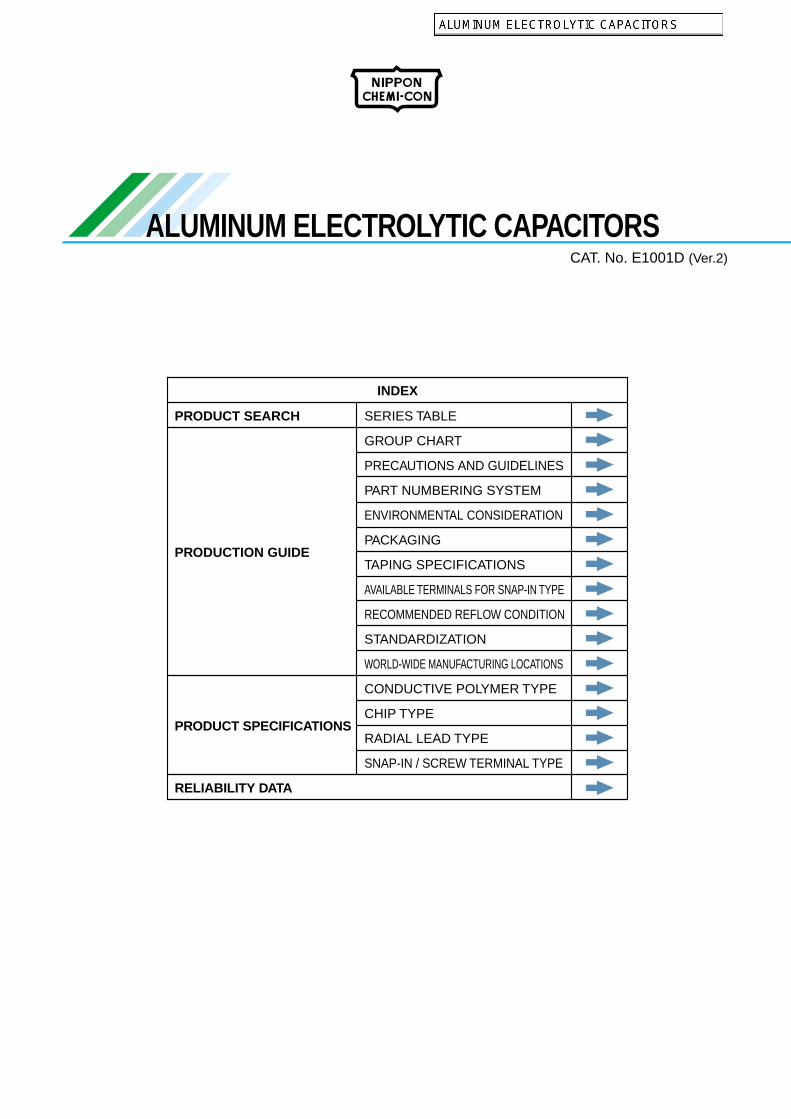
ALUMINUM ELECTROLYTIC CAPACITORS INDEX PRODUCT SEARCH PRODUCTION GUIDE PRODUCT SPECIFICATIONS RELIABILITY DATA SERIES TABLE GROUP CHART PRECAUTIONS AND GUIDELINES PART NUMBERING SYSTEM ENVIRONMENTAL CONSIDERATION PACKAGING TAPING SPECIFICATIONS AVAILABLE TERMINALS FOR SNAP-IN TYPE RECOMMENDED REFLOW CONDITION STANDARDIZATION WORLD-WIDE MANUFACTURING LOCATIONS CONDUCTIVE POLYMER TYPE CHIP TYPE RADIAL LEAD TYPE SNAP-IN / SCREW TERMINAL TYPE CAT. No. E1001D (Ver.2)
Transcript
ALUMINUM ELECTROLYTIC CAPACITORS
INDEX
PRODUCT SEARCH
PRODUCTION GUIDE
PRODUCT SPECIFICATIONS
RELIABILITY DATA
SERIES TABLE
GROUP CHART
PRECAUTIONS AND GUIDELINES
PART NUMBERING SYSTEM
ENVIRONMENTAL CONSIDERATION
PACKAGING
TAPING SPECIFICATIONS
AVAILABLE TERMINALS FOR SNAP-IN TYPE
RECOMMENDED REFLOW CONDITION
STANDARDIZATION
WORLD-WIDE MANUFACTURING LOCATIONS
CONDUCTIVE POLYMER TYPE
CHIP TYPE
RADIAL LEAD TYPE
SNAP-IN / SCREW TERMINAL TYPE
CAT. No. E1001D (Ver.2)
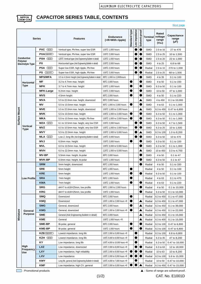
CAPACITOR SERIES TABLE, CONTENTS
CAT. No. E1001D
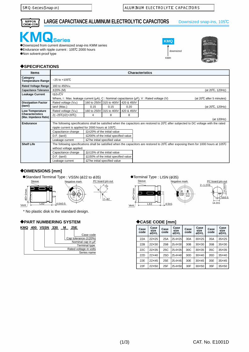
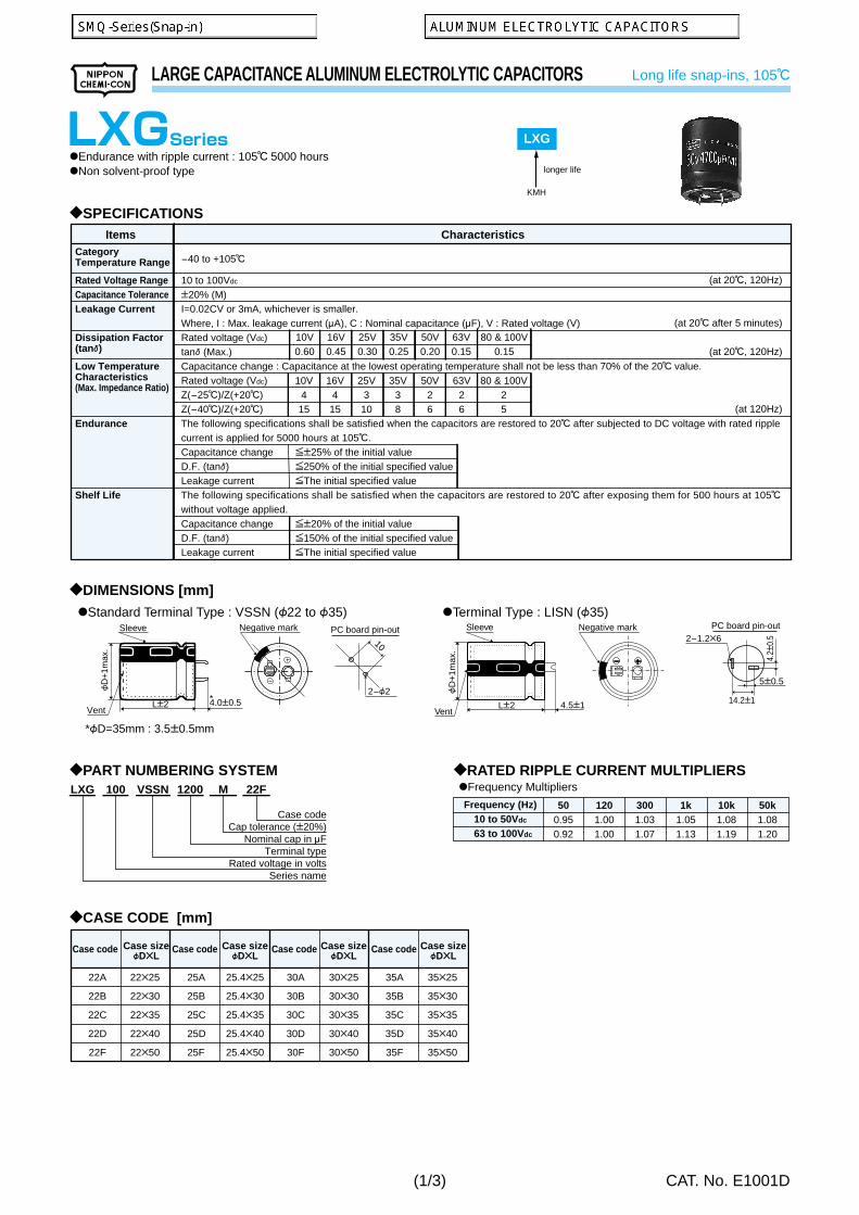
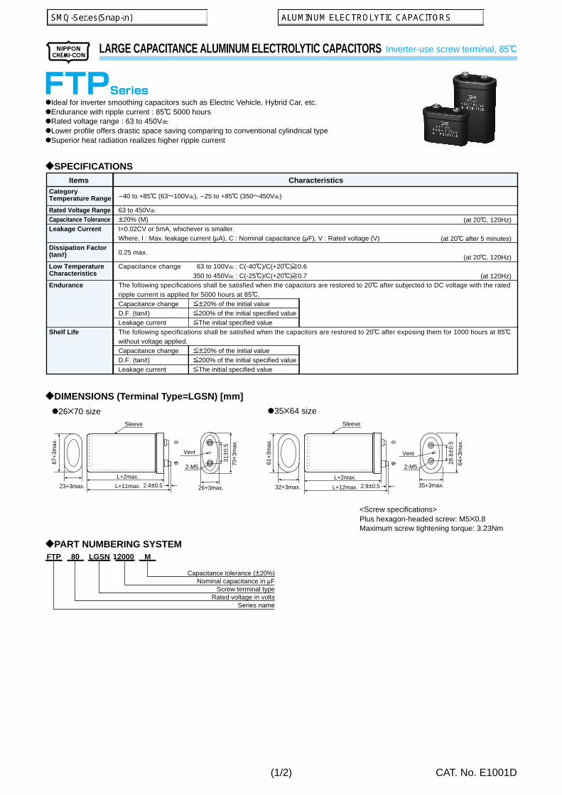
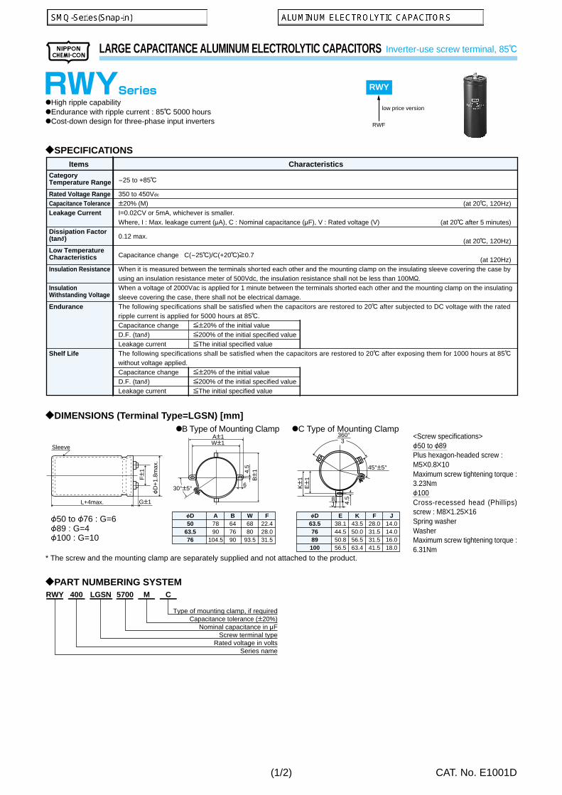
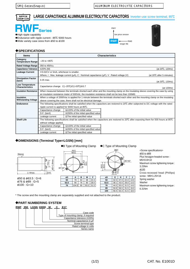
Series FeaturesEndurance
(+R=With ripple)Terminal
type
HorizontalType
VerticalType
Sur
face
Mou
ntM
inia
ture
ConductivePolymerElectrolyte Type
Low Profile
GeneralPurpose
HighFrequencyUse
Sta
ndar
d ty
pe
Sol
vent
-pro
of
Low
impe
danc
e
Ratedvoltagerange(Vdc)
Capacitancerange(mF)
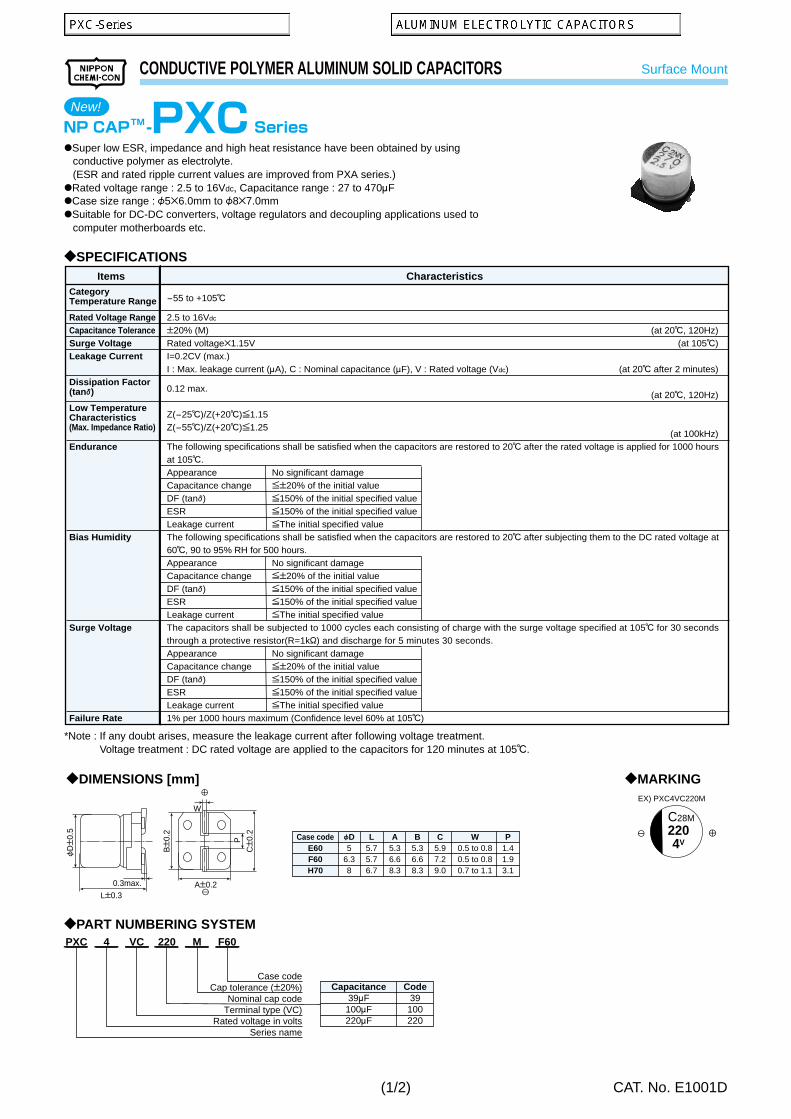
Vertical type, Pb-free, super low ESR
Vertical type, Pb-free, super low ESR
125C Vertical type (Ask Engineering Bulletin in detail)
Horizontal type (Ask Engineering Bulletin in detail)
Super low ESR, high ripple, Pb-free
Super low ESR, high ripple, Pb-free
3.5 to 4.5mm height (Ask Engineering Bulletin in detail)
3.2 to 4.7mm max. height
3.7 to 4.7mm max. height
9.2mm max. height
4.5mm height
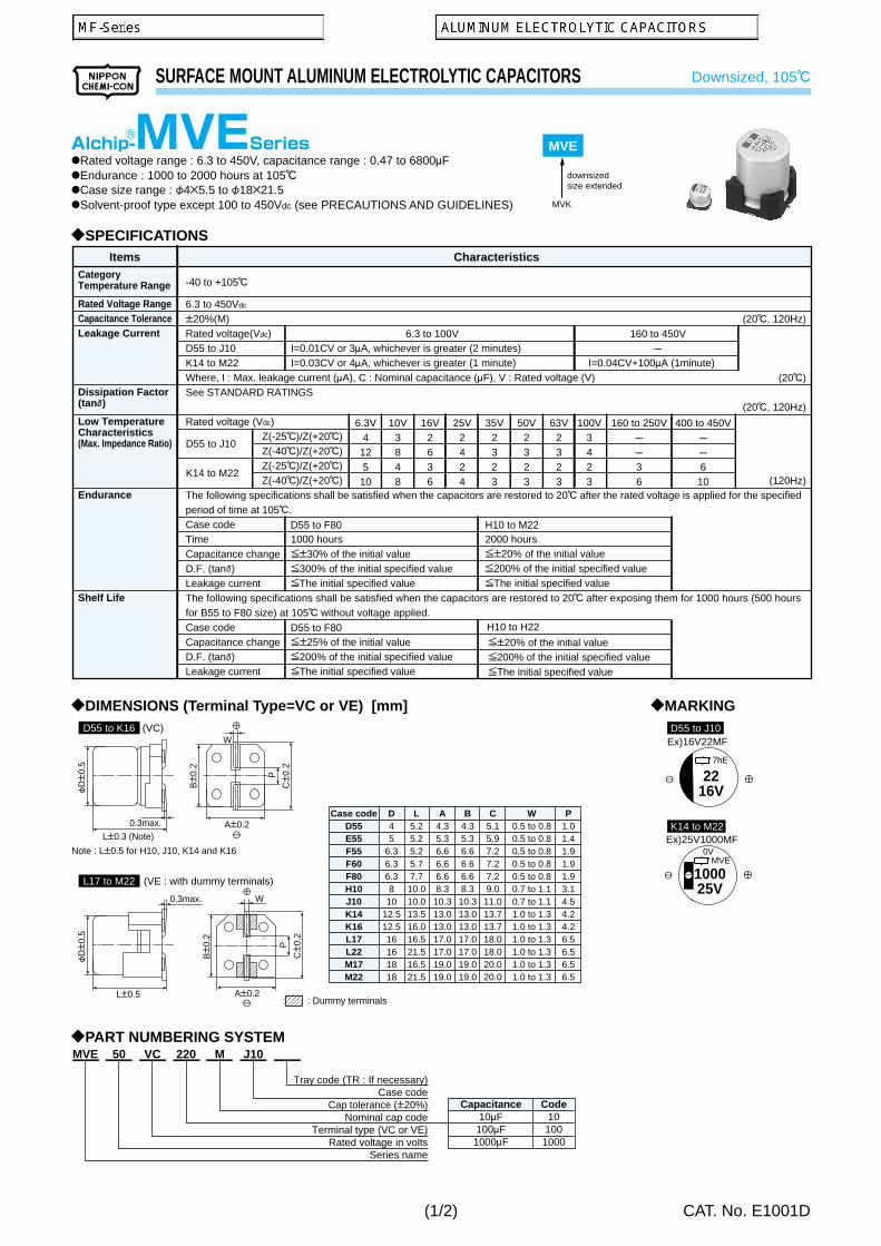
5.5 to 22.0mm max. height, downsized
5.5 to 10.5mm max. height
5.5 to 22.0mm max. height, downsized
5.5 to 10.5mm max. height
5.5 to 10.5mm max. height, Pb-free
6.1 to 10.5mm max. height, very low ESR
6.0 to 10.5mm max. height, very low ESR
5.5 to 22.0mm max. height
Low Z, long life (Ask Engineering Bulletin in detail)
6.0mm max. height
6.0 to 10.5mm max. height
6.0 to 22.0mm max. height
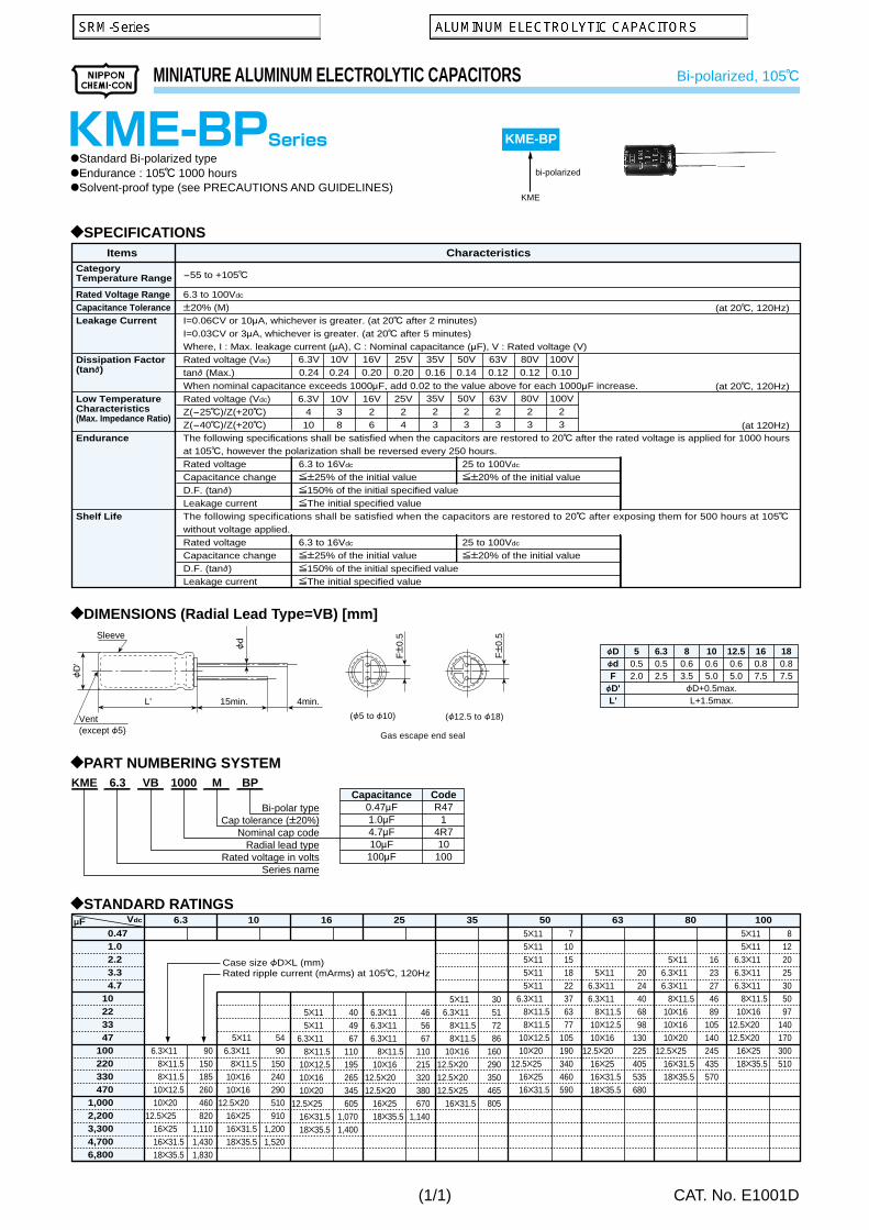
5.5mm max. height, bi-polar
6.0mm max. height, bi-polar
5mm height, downsized
5mm height
5mm height
7mm height
7mm height
F4B7 to F18B25mm, low profile
F4B7 to F18B25mm, low profile
Downsized
Downsized
General, downsized
General, downsized
General (Ask Engineering Bulletin in detail)
General
Bi-polar, general
Bi-polar, general
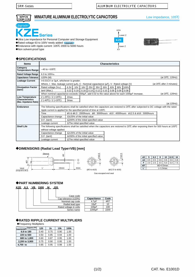
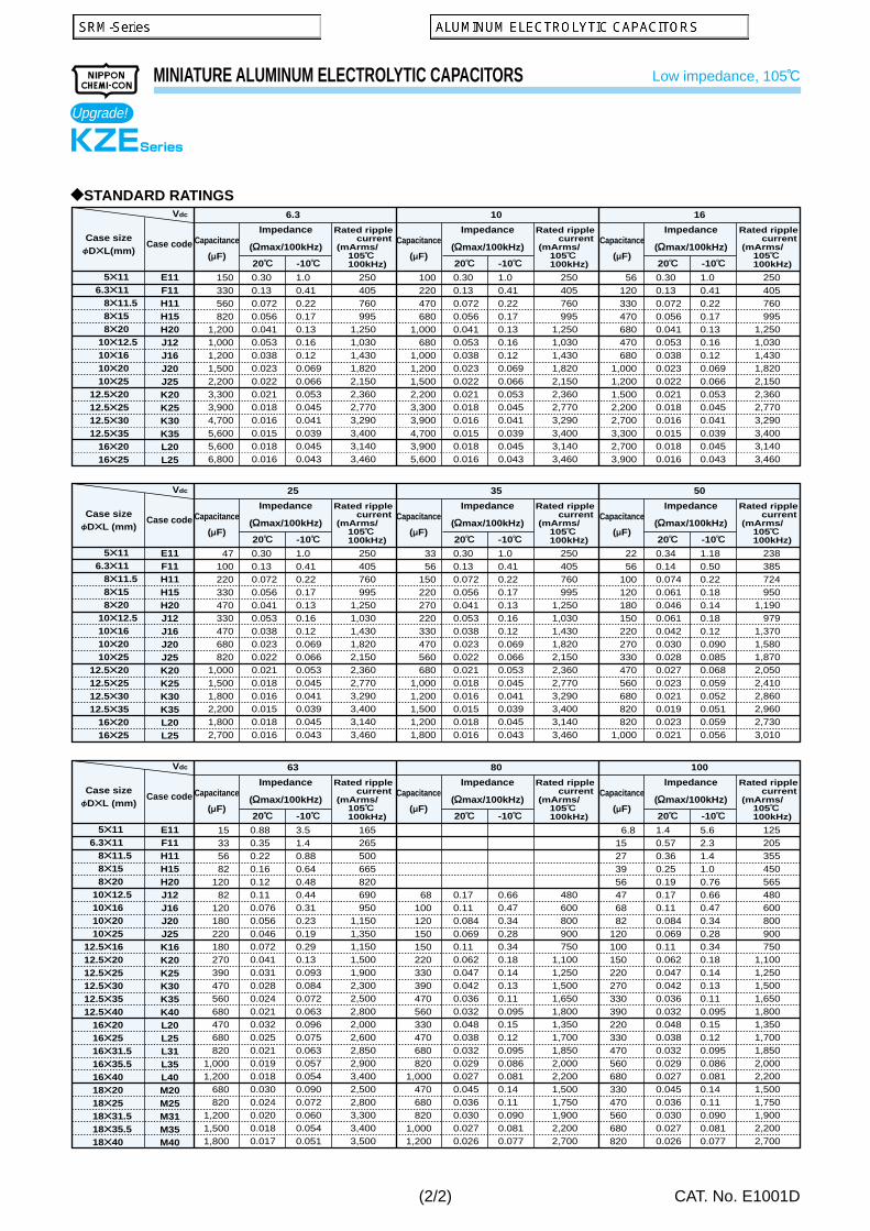
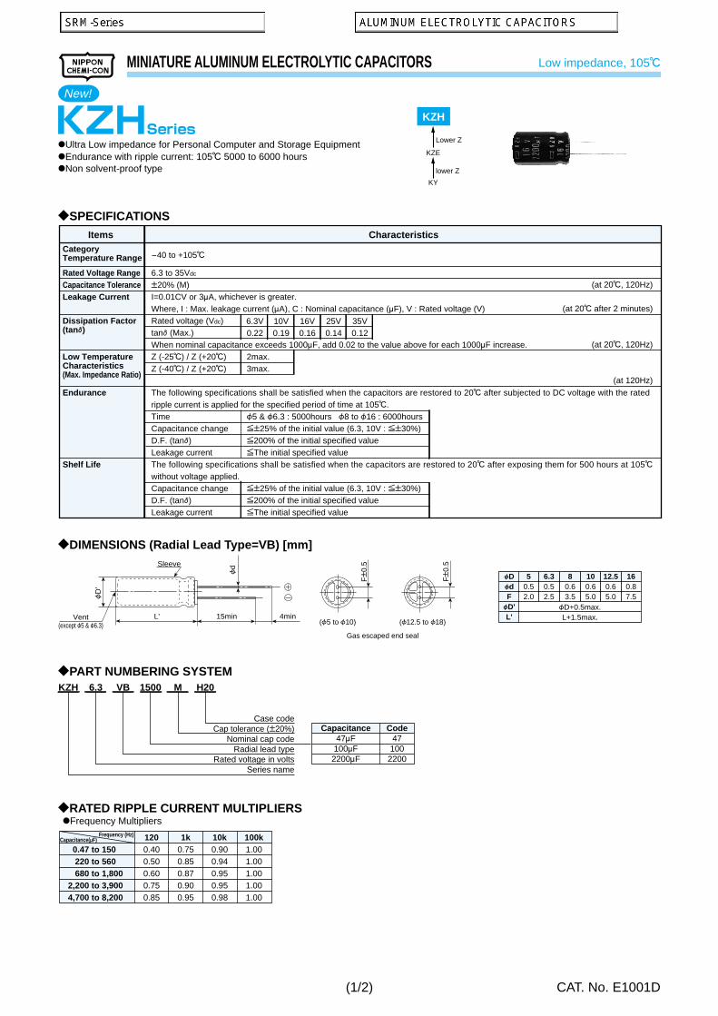
Lowest impedance, long life
Lowest impedance, long life
Low impedance, long life
Low impedance, downsized
Low impedance, high reliability
Low impedance
Long life, general (Ask Engineering Bulletin in detail)
Low impedance, high CV, general
SMD
SMD
SMD
SMD
Radial
Radial
SMD
SMD
SMD
SMD
SMD
SMD
SMD
SMD
SMD
SMD
SMD
SMD
SMD
SMD
SMD
SMD
SMD
SMD
SMD
Radial
Radial
Radial
Radial
Radial
Radial
Radial
Radial
Radial
Radial
Radial
Radial
Radial
Radial
Radial
Radial
Radial
Radial
Radial
Radial
Radial
Radial
Radial
2.5 to 16
2.5 to 25
2.5 to 20
4 to 25
2.5 to 10
2.5 to 25
4 to 35
4 to 50
6.3 to 50
10 to 50
4 to 50
4 to 450
4 to 63
6.3 to 450
6.3 to 50
6.3 to 50
6.3 to 50
6.3 to 25
6.3 to 100
6.3 to 50
6.3 to 50
6.3 to 50
10 to 450
4 to 50
6.3 to 50
4 to 50
4 to 50
6.3 to 50
4 to 63
4 to 63
4 to 50
6.3 to 50
6.3 to 450
6.3 to 450
6.3 to 450
6.3 to 450
6.3 to 450
6.3 to 400
6.3 to 100
6.3 to 100
6.3 to 100
6.3 to 35
6.3 to 50
6.3 to 63
10 to 63
6.3 to 100
10 to 50
6.3 to 450
27 to 470
10 to 1,500
22 to 1,000
6.8 to 68
270 to 1,000
68 to 1,500
0.1 to 100
0.1 to 150
0.1 to 100
47 to 1,000
0.1 to 220
0.1 to 10,000
0.1 to 1,000
0.47 to 6,800
0.1 to 1,000
0.1 to 1,000
4.7 to 1,500
10 to 1,500
1.0 to 8,200
10 to 470
0.1 to 100
0.1 to 1,000
3.3 to 4,700
0.1 to 47
0.1 to 47
0.1 to 330
0.1 to 100
0.1 to 100
0.1 to 470
0.1 to 220
0.1 to 10,000
0.1 to 10,000
0.1 to 47,000
0.1 to 47,000
0.1 to 39,000
0.1 to 22,000
0.1 to 15,000
0.1 to 15,000
0.47 to 6,800
0.47 to 6,800
6.8 to 6,800
47 to 8,200
0.47 to 18,000
12 to 18,000
10 to 8,200
5.6 to 15,000
0.47 to 10,000
0.47 to 15,000
105C 1,000 hours
105C 2,000 hours
125C 1,000 hours
105C 2,000 hours
105C 2,000 hours
105C 2,000 hours
85C 1,000 to 2,000hours
85C 2,000 hours
105C 1,000 hours
105C 2,000 hours
85C 2,000 hours
85C 2,000 hours
85C 1,000 to 2,000 hours
105C 1,000 to 2,000 hours
105C 1,000 to 2,000 hours
105C 1,000 to 2,000 hours
105C 2,000 hours
105C 1,000 to 2,000 hours
105C 1,000 to 5,000 hours
105C 3,000 hours
105C 2,000 hours
105C 3,000 to 5,000 hours
125C 1,000 to 5,000 hours
85C 2,000 hours
105C 1,000 hours
85C 1,000 hours
85C 1,000 hours
105C 1,000 hours
85C 1,000 hours
105C 1,000 hours
85C 1,000 to 2,000 hours
105C 1,000 hours
85C 2,000 hours
105C 1,000 to 2,000 hours +R
85C 2,000 hours
105C 1,000 to 2,000 hours +R
85C 2,000 hours
105C 1,000 hours +R
85C 2,000 hours
105C 1,000 hours
105C 2,000 to 5,000 hours +R
105C 5,000 to 6,000 hours +R
105C 4,000 to 10,000 hours +R
105C 2,000 to 8,000 hours +R
105C 2,000 to 8,000 hours +R
105C 2,000 to 5,000 hours +R
105C 4,000 to 7,000 hours +R
105C 2,000 to 5,000 hours +R
PXC
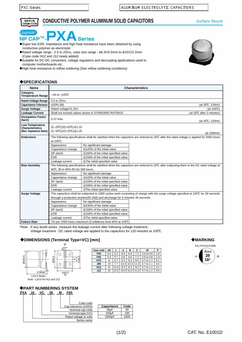
PXA
PXH
PX
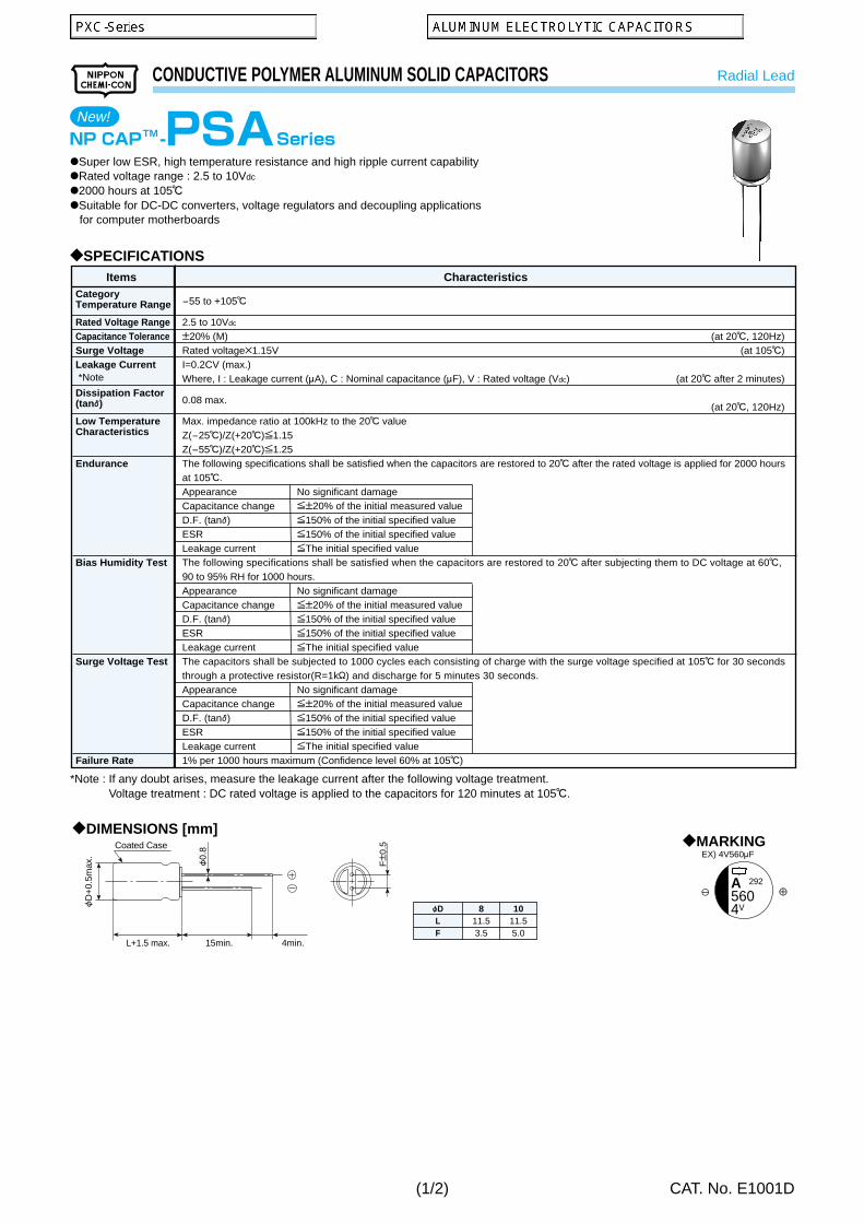
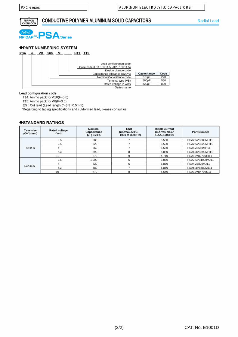
PSA
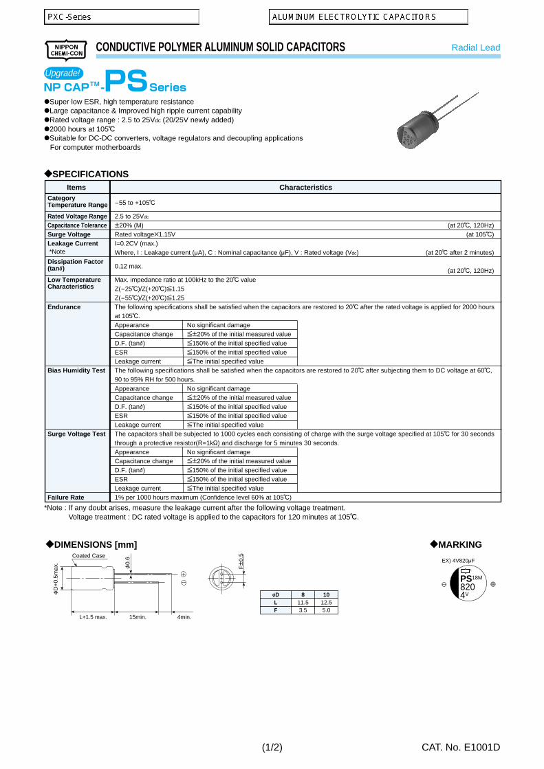
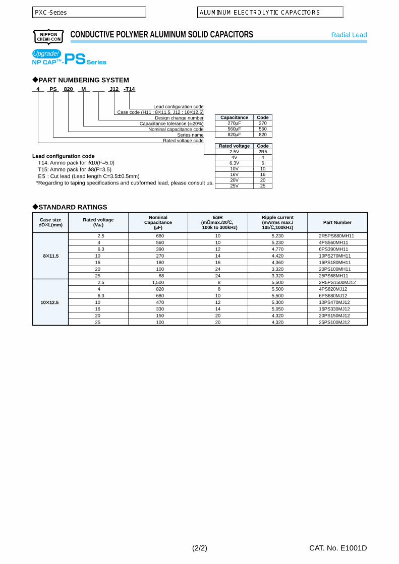
PS
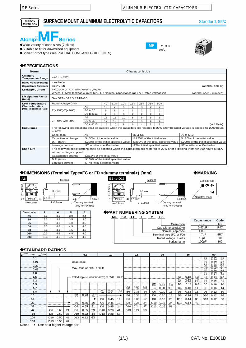
MFS/MFA
MF
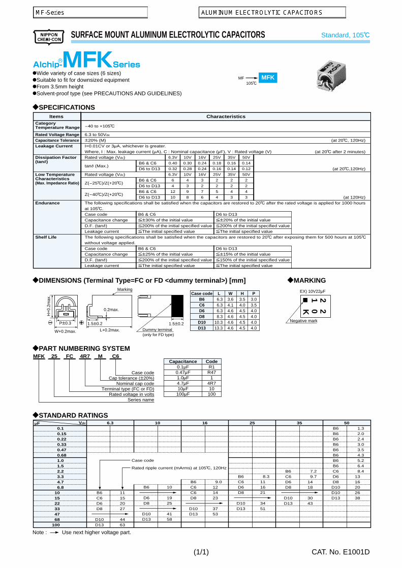
MFK
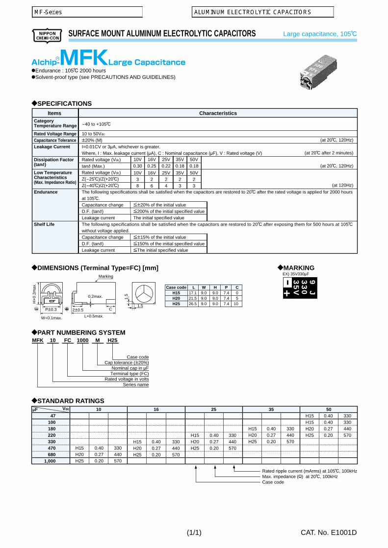
MFK-Large
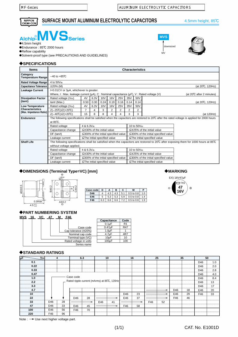
MVS
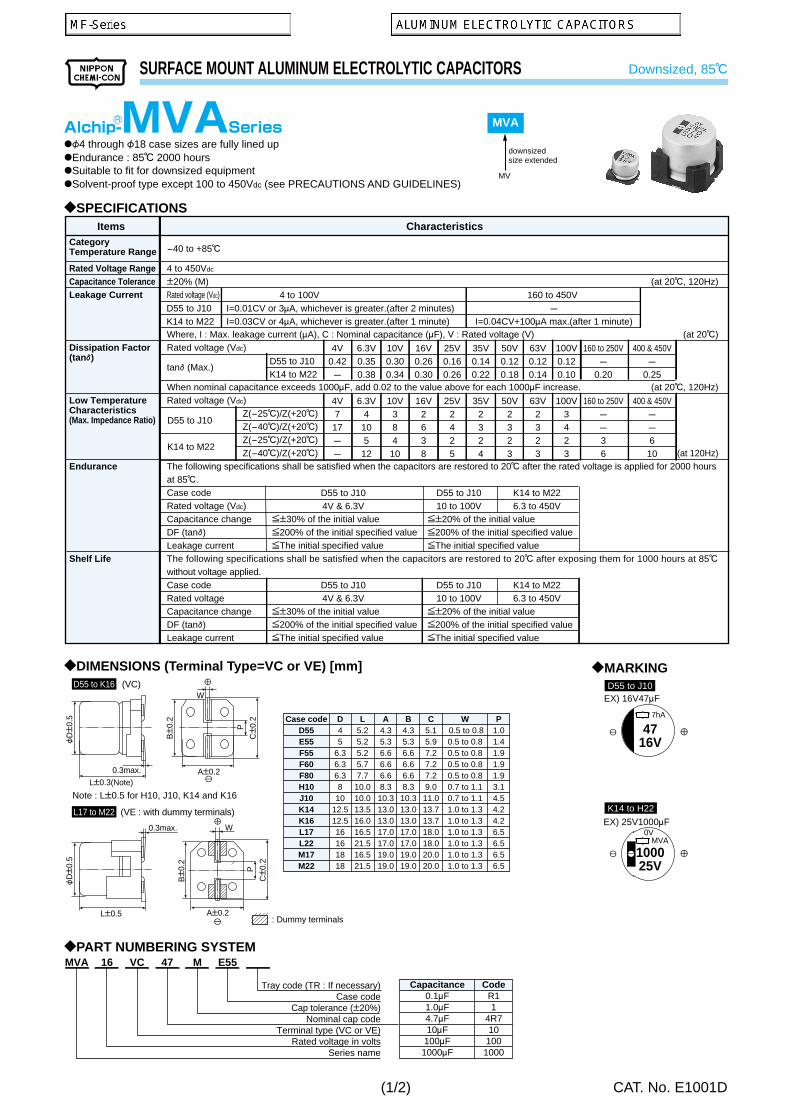
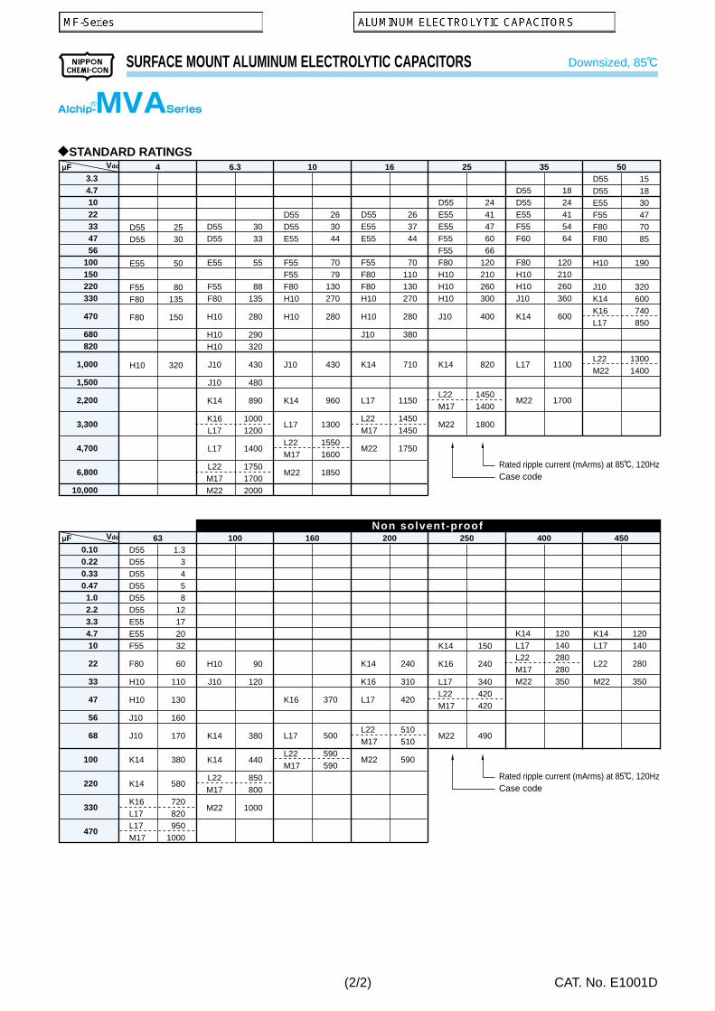
MVA
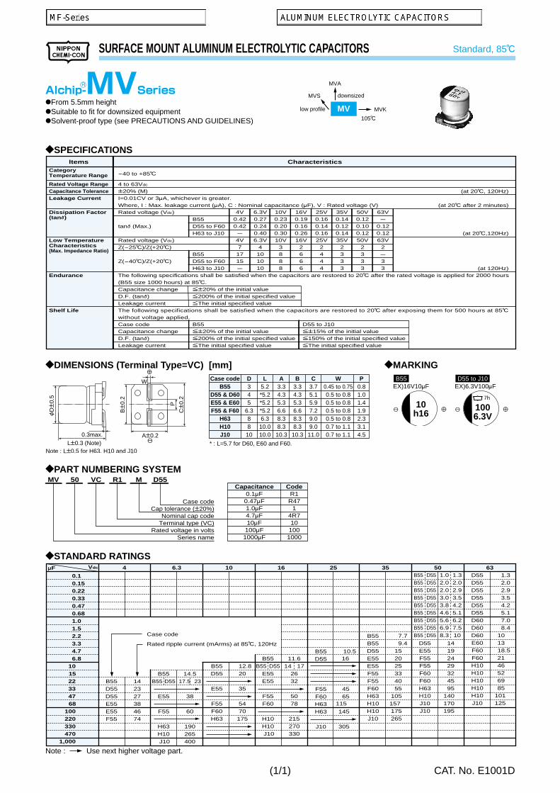
MV
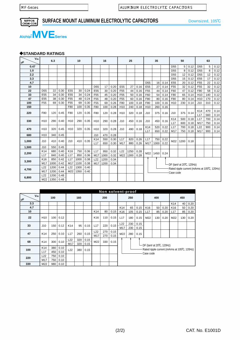
MVE
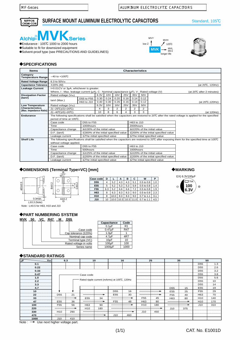
MVK
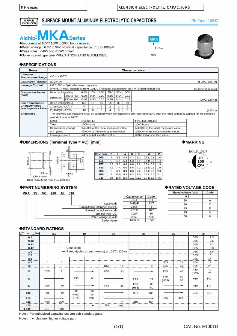
MKA
MZA
MVZ
MVY
MLA
MVJ
MVL
MVH
MV-BP
MVK-BP
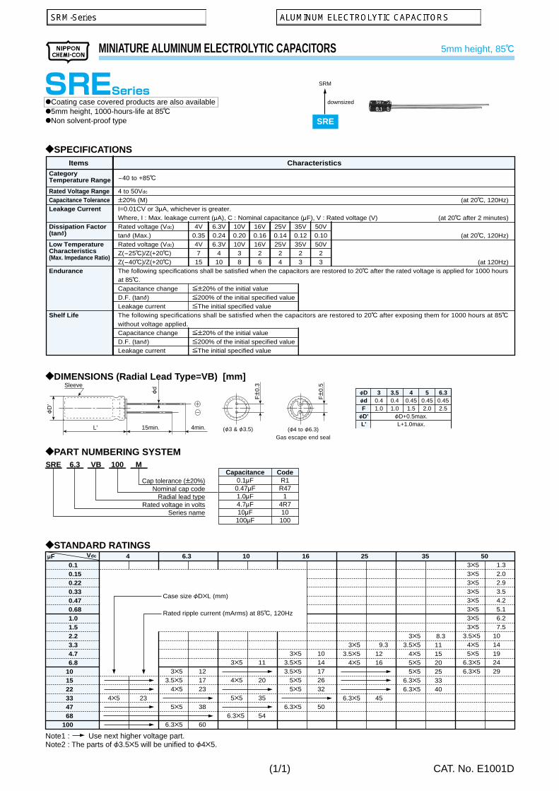
SRM
SRE
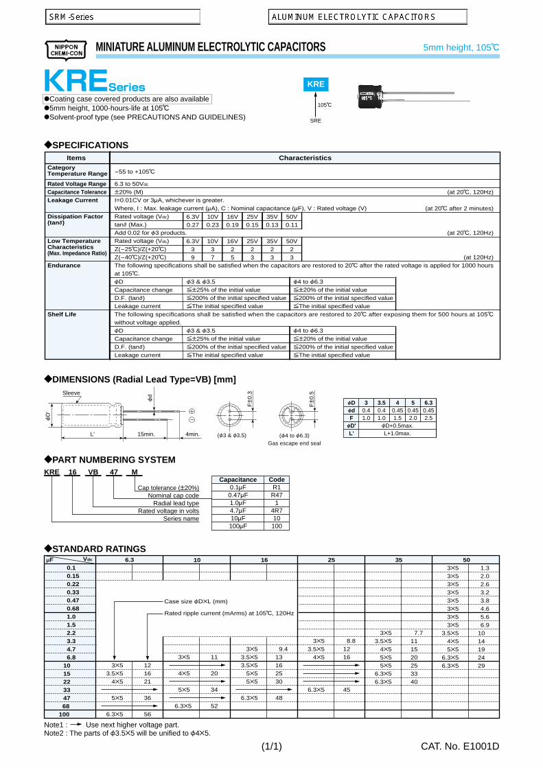
KRE
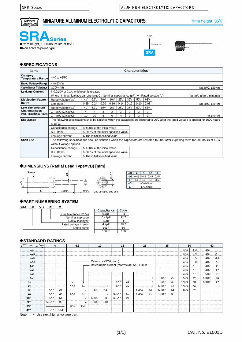
SRA
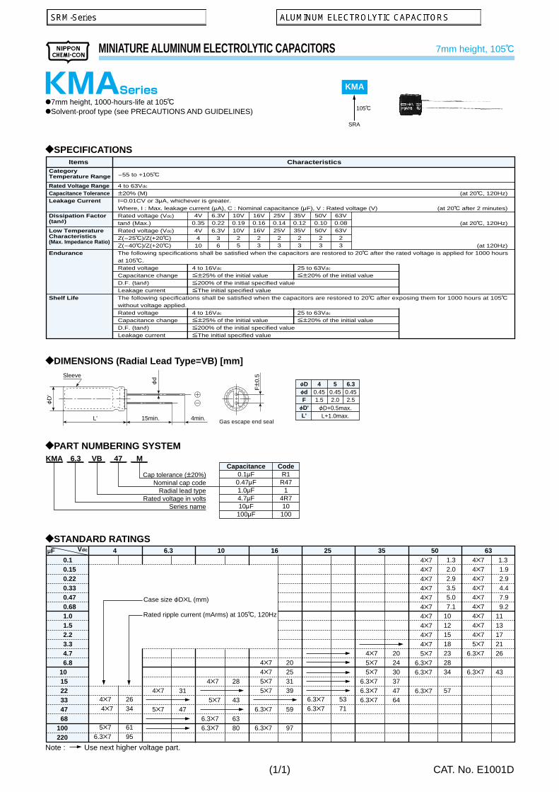
KMA
SRG
KRG
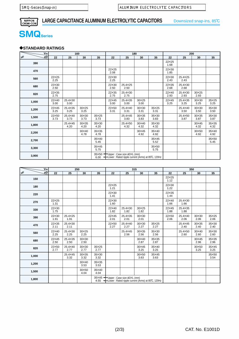
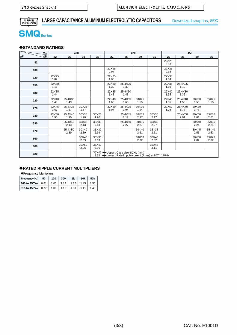
SMQ
KMQ
SMG
KMG
SME
KME
SME-BP
KME-BP
KZE
KZH
KY
LXZ
LXY
LXV
KMY
KMF
NEW!
NEW!
NEW!
NEW!
NEW!
NEW!
Upgrade!
Upgrade!
Upgrade!
: Promotional products : Some of range are solvent-proof.
(1/2)
Next page
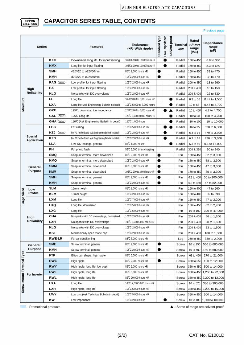
CAPACITOR SERIES TABLE, CONTENTS
CAT. No. E1001D
Downsized, long life, for input filtering
Long life, for input filtering
F20B20 to F22B50mm
F20B20 to F22B50mm
Low profile, for input filtering
Low profile, for input filtering
No sparks with DC overvoltage
Long life
Long life (Ask Engineering Bulletin in detail)
125C, downsize, low impedance
125C Long life
150C (Ask Engineering Bulletin in detail)
For airbag
For PC motherboard (Ask Engineering Bulletin in detail)
For PC motherboard (Ask Engineering Bulletin in detail)
Low DC leakage, general
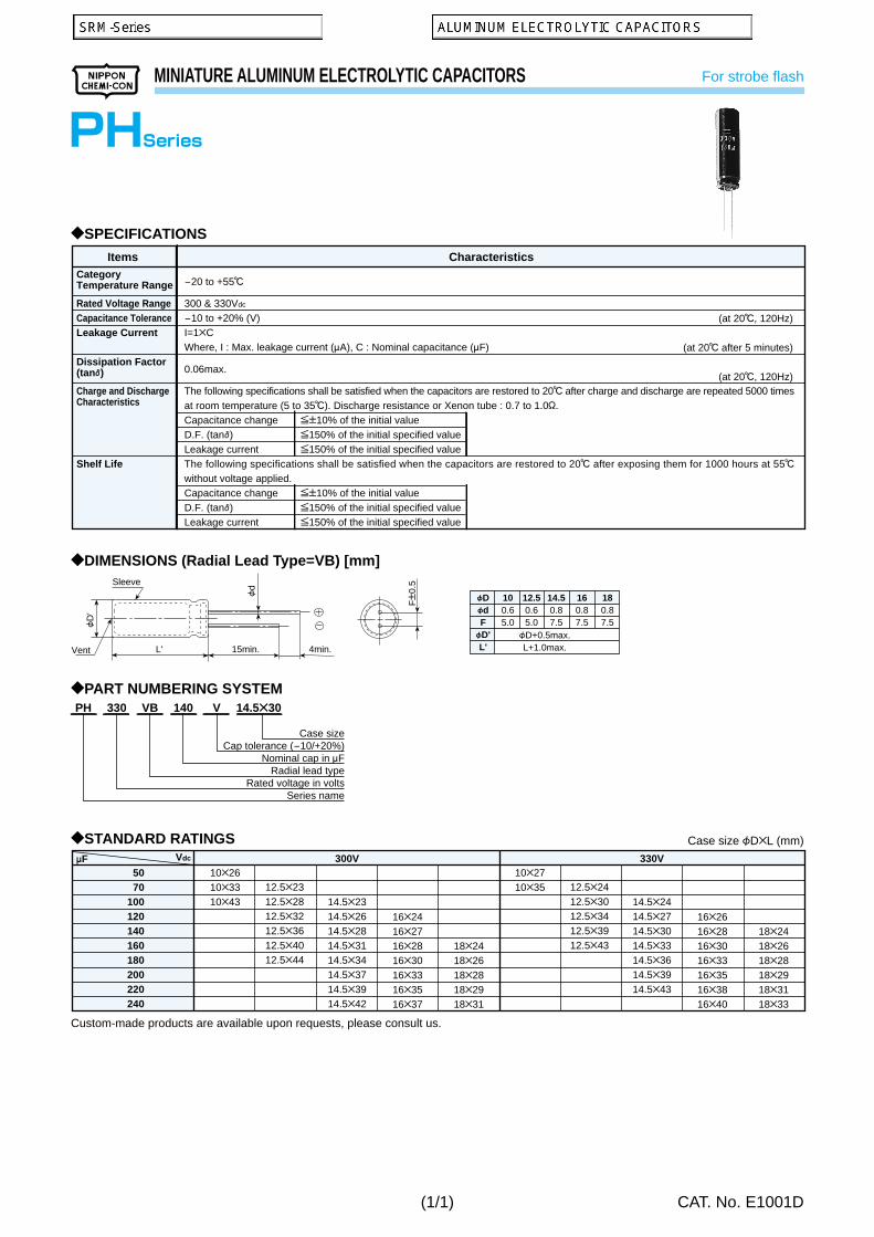
For photo flash
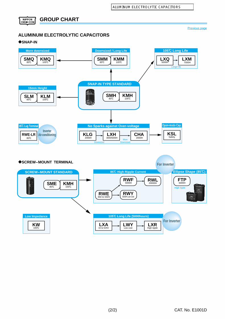
Snap-in terminal, more downsized
Snap-in terminal, more downsized
Snap-in terminal, downsized
Snap-in terminal, downsized
Snap-in terminal, general
Snap-in terminal, general
15mm height
15mm height
Long life
Long life, downsized
Long life
No sparks with DC overvoltage, downsized
No sparks with DC overvoltage
No sparks with DC overvoltage
Mechanically open mode cap
For air-conditioning
Screw terminal, general
Screw terminal, general
Ellips can shape, high ripple
High ripple
High ripple, long life, low cost
High ripple, long life
High ripple, long life
Long life
High ripple, long life
Low cost (Ask Technical Bulletin in detail)
Low impedance
Radial
Radial
Radial
Radial
Radial
Radial
Radial
Radial
Radial
Radial
Radial
Radial
Radial
Radial
Radial
Radial
Radial
Pin
Pin
Pin
Pin
Pin
Pin
Pin
Pin
Pin
Pin
Pin
Pin
Pin
Pin
Pin
Lug
Screw
Screw
Screw
Screw
Screw
Screw
Screw
Screw
Screw
Screw
Screw
160 to 450
160 to 450
160 to 450
160 to 450
200 to 450
200 & 400
200 & 400
6.3 to 50
10 to 63
10 to 450
10 to 50
10 to 100
16 to 35
6.3 to 16
6.3 to 16
6.3 to 50
300 & 330
160 to 450
160 to 450
160 to 450
160 to 450
6.3 to 450
6.3 to 450
160 to 400
160 to 400
160 to 450
160 to 450
10 to 100
200 & 400
200 & 400
200 & 400
200 & 400
250 to 450
10 to 250
10 to 400
63 to 450
350 to 550
350 to 450
350 to 450
350 to 450
10 to 525
350 to 450
350 to 450
10 to 100
6.8 to 330
3.3 to 680
33 to 470
33 to 470
18 to 560
10 to 150
22 to 330
0.47 to 1,500
0.47 to 4,700
4.7 to 4,700
100 to 4,700
10 to 10,000
820 to 6,800
470 to 3,300
470 to 3,300
0.1 to 15,000
50 to 240
82 to 3,900
68 to 3,300
47 to 3,300
39 to 3,300
56 to 100,000
47 to 82,000
47 to 560
39 to 390
47 to 2,200
82 to 2,700
390 to 47,000
56 to 1,200
68 to 1,500
33 to 1,500
180 to 1,500
330 to 2,200
560 to 680,000
180 to 680,000
270 to 21,000
100 to 12,000
500 to 14,000
1,200 to 22,000
2,200 to 12,000
330 to 390,000
2,200 to 15,000
500 to 14,000
1,000 to 100,000
105C 8,000 to 10,000 hours +R
105C 8,000 to 10,000 hours +R
85C 2,000 hours +R
105C 2,000 hours +R
105C 2,000 hours +R
105C 2,000 hours +R
105C 2,000 hours +R
105C 3,000 to 6,000 hours +R
105C 5,000 to 7,000 hours
125C 2,000 to 5,000 hours +R
125C 5,000/10,000 hours +R
150C 1,000 hours
105C 5,000 hours +R
105C 2,000 hours +R
105C 2,000 hours +R
85C 1,000 hours
55C 5,000 times charging
85C 2,000 hours +R
105C 2,000 hours +R
85C 3,000 hours +R
105C 2,000 to 3,000 hours +R
85C 2,000 hours +R
105C 2,000 hours +R
85C 2,000 hours +R
105C 2,000 hours +R
105C 7,000 hours +R
105C 5,000 hours +R
105C 5,000 hours +R
105C 2,000 hours +R
105C 3,000/5,000 hours +R
105C 2,000 hours +R
105C 2,000 hours +R
85C 3,000 hours +R
85C 2,000 hours +R
105C 2,000 hours +R
85C 5,000 hours +R
85C 2,000 hours +R
85C 5,000 hours +R
85C 5,000 hours +R
85C 20,000 hours +R
105C 2,000/5,000 hours +R
105C 5,000 hours +R
105C 5,000 hours +R
105C 2,000 hours
SpecialApplication
Min
iatu
re
GeneralPurpose
LowProfile
HighReliability
Larg
e S
ized
GeneralPurpose
For Inverter
Scr
ew-m
ount
Ter
min
al T
ype
Series FeaturesEndurance
(+R=With ripple)Terminal
type
Sta
ndar
d ty
pe
Sol
vent
-pro
of
Low
impe
danc
e
Ratedvoltagerange(Vdc)
Capacitancerange(mF)
HighReliability
KXG
KMX
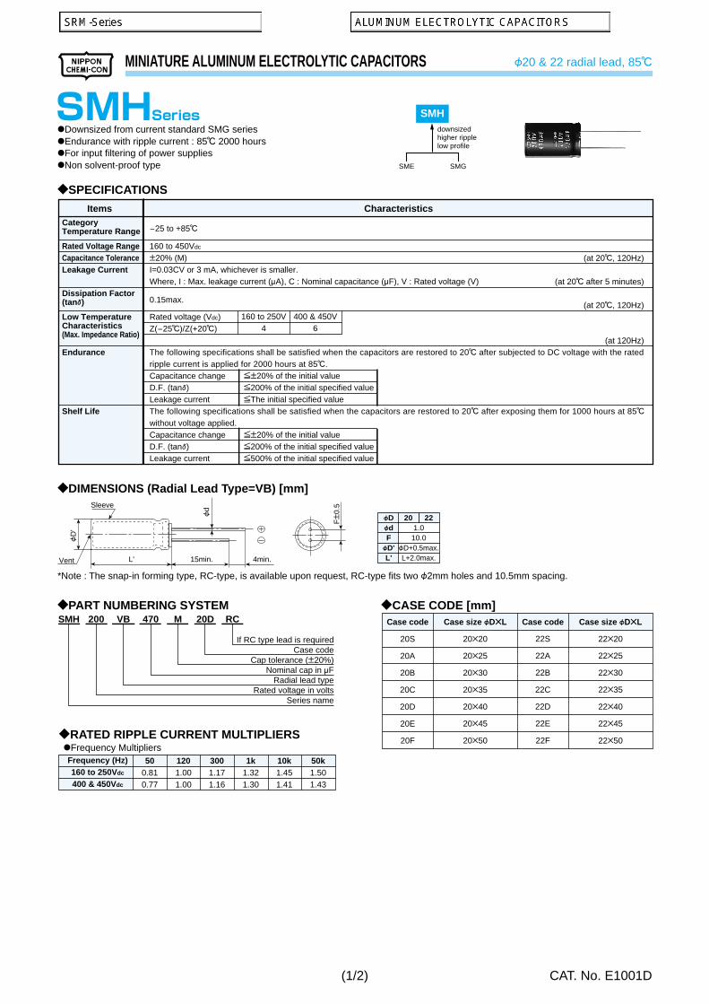
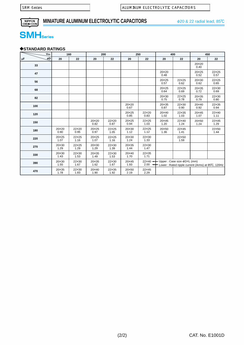
SMH
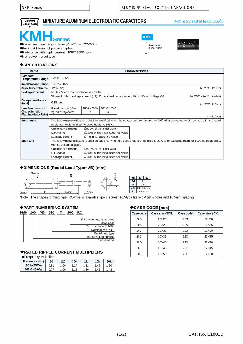
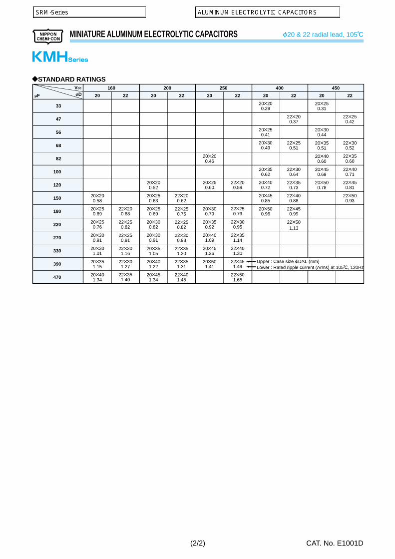
KMH
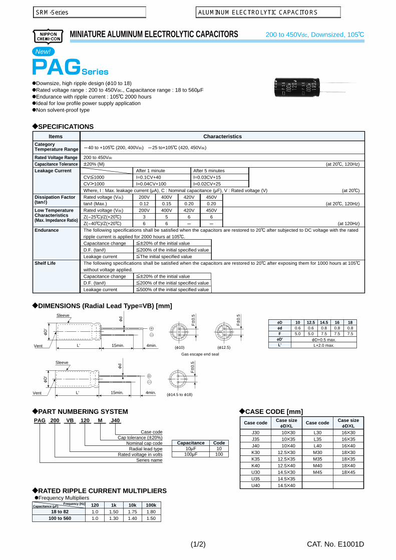
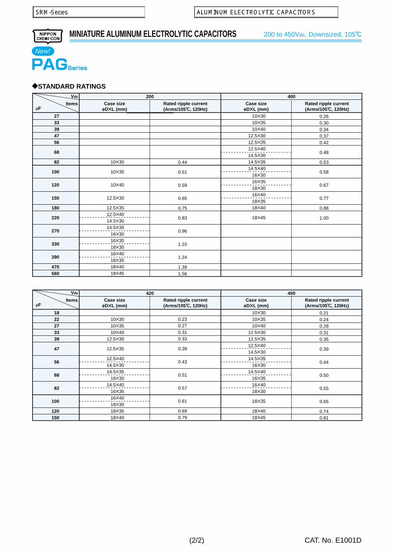
PAG
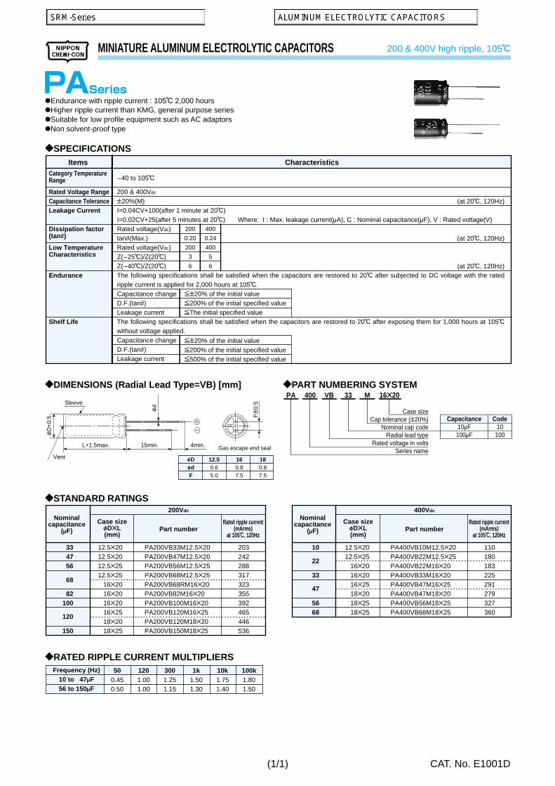
PA
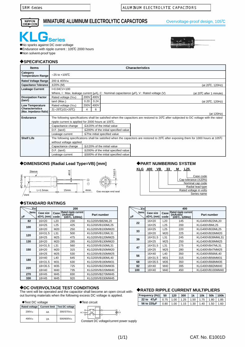
KLG
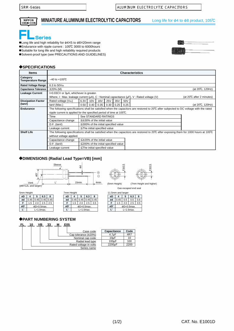
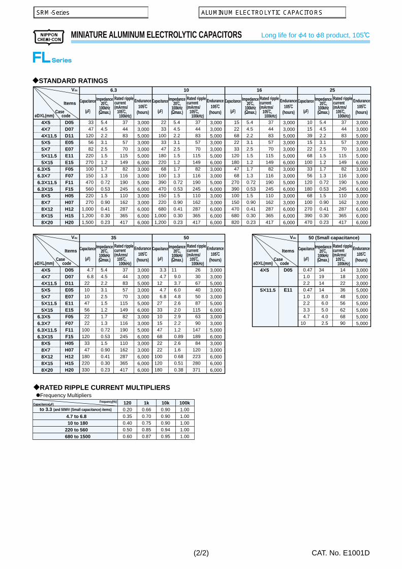
FL
LXA
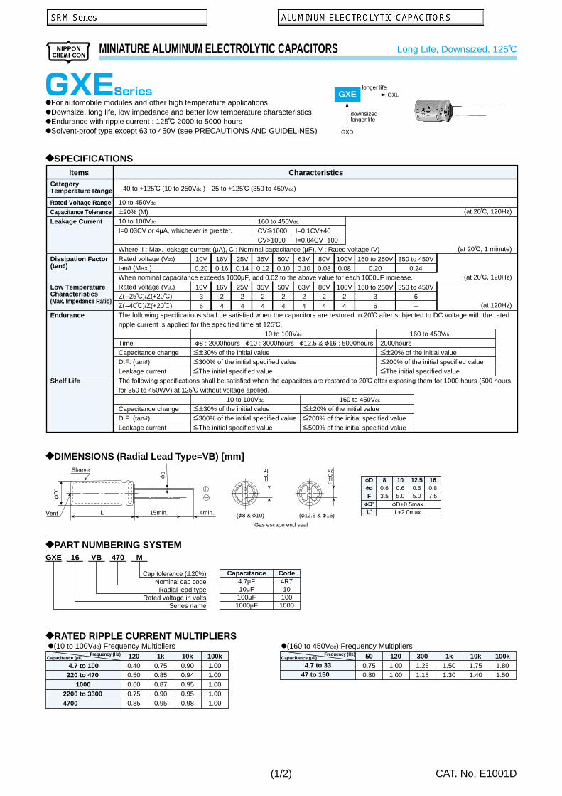
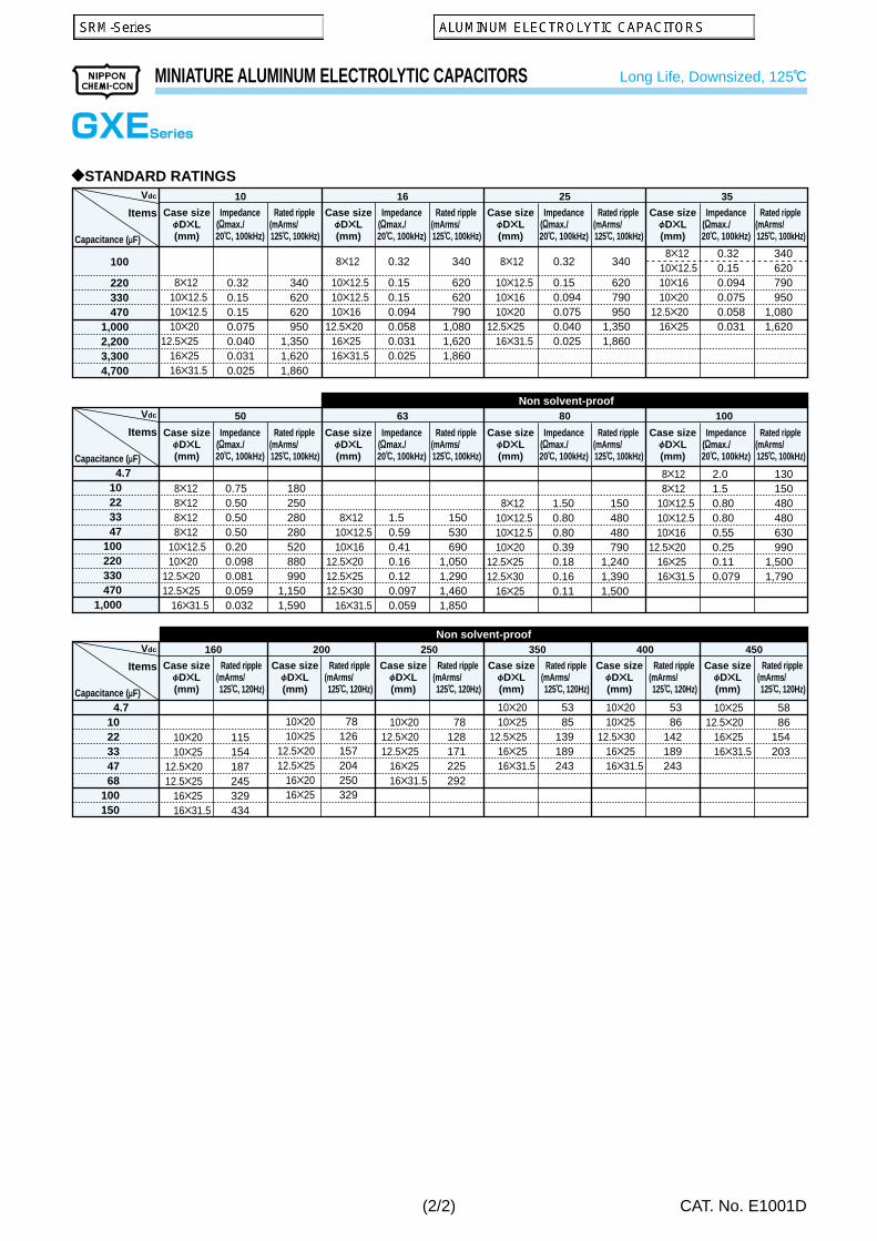
GXE
GXL
GHA
LBG
KZJ
KZG
LLA
PH
SMQ
KMQ
SMM
KMM
SMH
KMH
SLM
KLM
LXM
LXQ
LXG
CHA
LXH
KLG
KSL
RWE-LR
SME
KMH
FTP
RWE
RWY
RWF
RWL
LXA
LXR
LWY
KW
NEW!
NEW!
NEW!
NEW!
: Promotional products : Some of range are solvent-proof.
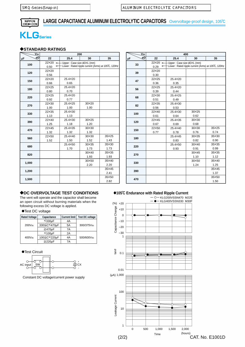
Aluminum Electrolytic Capacitors are polarized.Apply neither reverse voltage nor AC voltage to polarized ca-pacitors. Using reversed polarity causes a short circuit or vent-ing. Before use, refer to the catalog, product specifications orcapacitor body to identify the polarity marking. (The shape ofrubber seal does not represent the directional rule for polarity.)Use a bi-polar type of non-solid aluminum electrolytic capacitorfor a circuit where the polarity is occasionally reversed.However, note that even a bi-polar aluminum electrolytic ca-pacitor must not be used for AC voltage applications.
Do not apply a DC voltage which exceeds the full rated voltage.The peak voltage of a superimposed AC voltage (ripple current)on the DC voltage must not exceed the full rated voltage.A surge voltage value, which exceeds the full rated voltage, isprescribed in the catalogs, but it is a restricted condition, forespecially short periods of time.
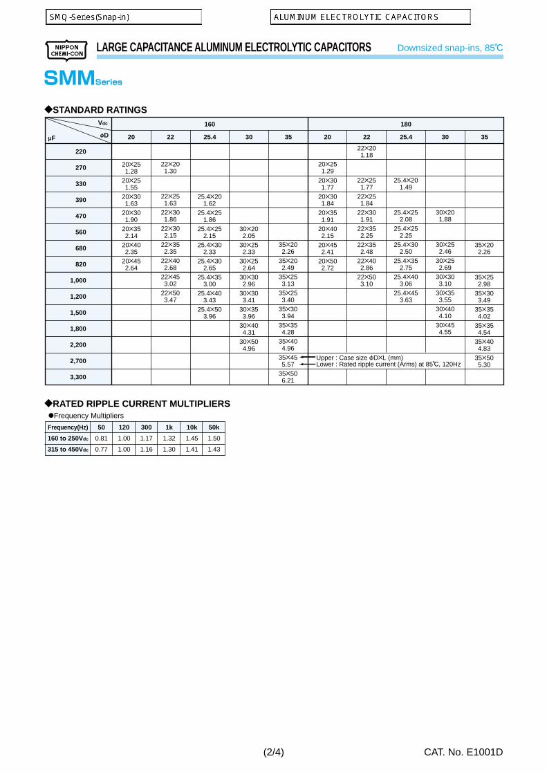
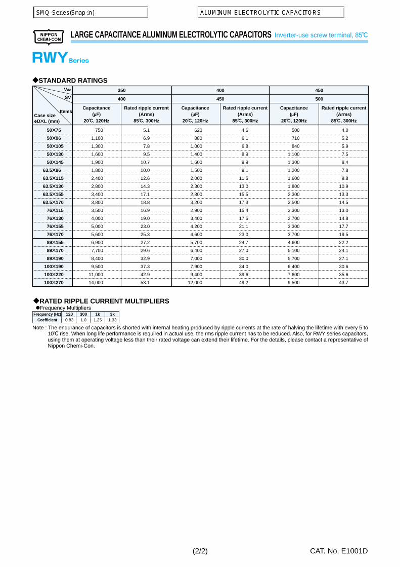
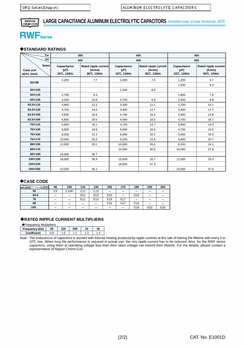
The rated ripple current has been specified at a certain ripplefrequency. The rated ripple current at several frequencies mustbe calculated by multiplying the rated ripple current at the origi-nal frequency using the frequency multipliers for each productseries. For more details, refer to the paragraph of Life of Alumi-num Electrolytic Capacitors.
The use of a capacitor outside the maximum rated categorytemperature will considerably shorten the life or cause the ca-pacitor to vent.The relation between the lifetime of aluminum electrolytic ca-pacitors and ambient temperature follows Arrhenius’ rule thatthe lifetime is approximately halved with each 10C rise in ambi-ent temperature.
Select the capacitors to meet the service life of a device.
Do not use capacitors in circuits where heavy charge anddischarge cycles are frequently repeated. Frequent and sharpheavy discharging cycles will result in decreasing capacitanceand damage to the capacitors due to generated heat. Speci-fied capacitors can be designed to meet the requirements ofcharging-discharging cycles, frequency, operating tempera-ture, etc.
Non-solid aluminum electrolytic capacitors, in general, have alifetime which ends in an open circuit, the period is dependentupon temperature. Consequently, lifetime of capacitors can beextended by reducing the ambient temperature and/or ripplecurrent.
a) Electrically isolate the following parts of a capacitor from thenegative terminal, the positive terminal and the circuit traces.· The outer can case of a non-solid aluminum capacitor.· The dummy terminal of a non-solid aluminum capacitor,
which is designed for mounting stability.
Select the capacitors to suit installation and operat-ing conditions, and use the capacitors to meet the per-formance limits prescribed in this catalog or the prod-uct specifications.
· The dummy terminal of a surface mount type capacitor suchas non-solid type MF/MFK series capacitors.
b) The outer sleeve of a capacitor is not assured as an insula-tor. For applications that require an insulated outer sleeve, acustom-design capacitor is recommended to.
Do not use/expose capacitors to the following conditions.a) Oil, water, salty water take care to avoid storage in damp
locations.b) Toxic gases such as hydrogen sulfide, sulfurous acid, nitrous
acid, chlorine or its compounds, and ammoniumc) Ozone, ultraviolet rays or radiationd) Severe vibration or mechanical shock conditions beyond
the limits prescribed in the catalogs or the product specifi-cation.
a) The paper separators and the electrolytic-conductive elec-trolytes in a non-solid aluminum electrolytic capacitor are flam-mable.Leaking electrolyte on a printed circuit board can graduallyerode the copper traces, possibly causing smoke or burningby short-circuiting the copper traces.Verify the following points when designing a PC board.· Provide the appropriate hole spacing on the PC board to
match the terminal spacing of the capacitor.· Make the following open space over the vent so that the
vent can operate correctly.
Case diameter Clearance
F6.3 to F16mm 2mm minimum F18 to F35mm 3mm minimum F40mm and up 5mm minimum
· Do not place any wires or copper traces over the vent of thecapacitor.
· Installing a capacitor with the vent facing the PC board needsan appropriate ventilation hole in PC board.
· Do not pass any copper traces beneath the seal side of acapacitor. The trace must pass 1 or 2mm to the side of thecapacitor.
· Avoid placing any heat-generating objects adjacent to a ca-pacitor or even on the reverse side of the PC board.
· Do not pass any via holes or underneath a capacitor.· In designing double-sided PC boards, do not locate any
copper trace under the seal side of a capacitor.b) Do not mount the terminal side of a screw mount capacitor
downwards. If a screw terminal capacitor is mounted on itsside, make sure the positive terminal is higher than the nega-tive terminal.Do not fasten the screws of the terminals and the mountingclamps over the specified torque prescribed in the catalog orthe production specification.
c) For a surface mount capacitor, design the copper pads ofthe PC board in accordance with the catalog or the prod-uct specifications.
a) The electrical characteristics of capacitors vary in respectto temperature, frequency and service life. Design the de-vice circuits by taking these changes into account.
b) Capacitors mounted in parallel need the current to flowequally through the individual capacitors.
c) Capacitors mounted in series require resistors in parallelwith the individual capacitors to balance the voltage.
Designing Device Circuits
Others12
Polarity
Condition
Mounting11
10
2
1
Operating voltage
Category temperature
Ripple current
Life expectancy
Charge and discharge
Failure mode of capacitors
Insulating9
8
7
6
5
4
3
(1/10)
PRECAUTIONS AND GUIDELINES
CAT. No. E1001D
a) Used capacitors are not reusable, except in the case that thecapacitors are detached from a device for periodic inspec-tion to measure their electrical characteristics.
b) If the capacitors have self charged, discharge in the capaci-tors through a resistor of approximately 1kO before use.
c) If capacitors are stored at a temperature of 35C or more andmore than 75%RH, the leakage current may increase. In thiscase, they can be reformed by applying the rated voltagethrough a resistor of approximately 1kO.
d) Verify the rated capacitance and voltages of the capacitorswhen installing.
f ) Verify the polarity of the capacitors.g) Do not use the capacitors if they have been dropped on the floor.h) Do not deform the cases of capacitors.g) Verify that the lead spacing of the capacitor fits the hole spac-
ing in the PC board before installing the capacitors. Somestandard pre-formed leads are available.
h) For pin terminals or snap-in terminals, insert the terminals intoPC board and press the capacitor downward until the bottom ofthe capacitor body reaches PC board surface.
i ) Do not apply any mechanical force in excess of the limitsprescribed in the catalogs or the product specifications ofthe capacitors.Also, note the capacitors may be damaged by mechanicalshocks caused by the vacuum/insertion head, componentchecker or centering operation of an automatic mounting orinsertion machine.
a) When soldering with a soldering iron· Soldering conditions (temperature and time) should be within
the limits prescribed in the catalogs or the product specifi-cations.
· If the terminal spacing of a capacitor does not fit the termi-nal hole spacing of the PC board, reform the terminals in amanner to minimize a mechanical stress into the body ofthe capacitor.
· Remove the capacitors from the PC board, after the solderis completely melted, reworking by using a soldering ironminimizes the mechanical stress to the capacitors.
· Do not touch the capacitor body with the hot tip of the sol-dering iron.
b) Flow soldering· Do not dip the body of a capacitor into the solder bath only
dip the terminals in. The soldering must be done on thereverse side of PC board.
· Soldering conditions (preheat, solder temperature and dip-ping time) should be within the limits prescribed in the cata-logs or the product specifications.
· Do not apply flux to any part of capacitors other than theirterminals.
· Make sure the capacitors do not come into contact with anyother components while soldering.
c) Reflow soldering· Soldering conditions (preheat, solder temperature and dip-
ping time) should be within the limits prescribed in the cata-logs or the product specifications.
· When setting the temperature infrared heaters, considerthat the infrared absorption causes material to be discol-ored and change in appearance.
· Do not solder capacitors more than once using reflow. Ifyou need to twice, be sure to consult us.
· Make sure capacitors do not come into contact with coppertraces.
d) Do not re-use surface mount capacitors which have alreadybeen soldered.
In addition, when installing a new capacitor onto the assem-bly board to rework, remove old residual flux from the sur-face of the PC board, and then use a soldering iron withinthe prescribed conditions.
Do not apply any mechanical stress to the capacitor aftersoldering onto the PC board.a) Do not lean or twist the body of the capacitor after solder-
ing the capacitors onto the PC board.b) Do not use the capacitors for lifting or carrying the assembly
board.c) Do not hit or poke the capacitor after soldering to PC board.
When stacking the assembly board, be careful that other com-ponents do not touch the aluminum electrolytic capacitors.
d) Do not drop the assembly board.
a) Do not wash capacitors by using the following cleaning agents.Solvent-proof capacitors are only suitable for washing usingthe cleaning conditions prescribed in the catalogs or the prod-uct specifications. In particular, ultrasonic cleaning will ac-celerate damaging capacitors.· Halogenated solvents; cause capacitors to fail due to cor-
rosion.· Alkali system solvents; corrode (dissolve) an aluminum
case.· Petroleum system solvents; cause the rubber seal mate-
rial to deteriorate.· Xylene; causes the rubber seal material to deteriorate.· Acetone; erases the marking.
b) Verify the following points when washing capacitors.· Monitor conductivity, pH, specific gravity, and the water
content of cleaning agents. Contamination adversely af-fects these characteristics.
· Be sure not to expose the capacitors under solvent richconditions or keep capacitors inside a closed container.In addition, please dry the solvent sufficiently on the PCboard and the capacitor with an air knife (temperatureshould be less than the maximum rated category tem-perature of the capacitor) over 10 minutes.Aluminum electrolytic capacitors can be characteristicallyand catastrophically damaged by halogen ions, particu-larly by chlorine ions, though the degree of the damagemainly depends upon the characteristics of the electro-lyte and rubber seal material. When halogen ions comeinto contact with the capacitors, the foil corrodes whenvoltages applied. This corrsion causes ; extremely highleakage current, which causes in line with, venting, andan open circuit.Global environmental warnings (Greenhouse effects andother environmental destruction by depletion of the ozonelayer), new types of cleaning agents have been devel-oped and commercialized as substitutes for CFC-113,1,1,2-trichloroethlene and 1,1,1-trichloroethylene.The following are recommended as cleaning conditionsfor some of new cleaning agents.
-Higher alcohol system cleaning agentsRecommended cleaning agents:Pine Alpha ST-100S (Arakawa Chemical)Clean Through 750H, 750K, 750L, and 710M (Kao)Technocare FRW-14 through 17 (Toshiba)Cleaning conditions:Using these cleaning agents capacitors are capable of with-standing immersion or ultrasonic cleaning for 10 minutes ata maximum liquid temperature of 60C. Find optimum condi-tion for washing, rinsing, and drying. Be sure not to rub themarking off the capacitor by contacting any other components
Installing Capacitors
Cleaning PC board
Handling after soldering
Installing
Soldering and Solderability
4
3
2
1
(2/10)
PRECAUTIONS AND GUIDELINES
CAT. No. E1001D
or the PC board. Note that shower cleaning adversely affectsthe markings on the sleeve.
-Non-Halogenated Solvent CleaningAK225AES (Asahi Glass)Cleaning conditions:Solvent-proof capacitors are capable of withstanding any oneof immersion, ultrasonic or vapor cleaning for 5 minutes; ex-ception is 2 minutes max. for KRE, and KRE-BP series ca-pacitors and 3 minutes for SRM series capacitors. However,from a view of the global environmental problems, these typesof solvent will be banned in near future. We would recom-mended not using them as much as possible.
Isopropyl alcohol cleaning agentsIPA (Isopropyl Alcohol) is one of the most acceptable clean-ing agents; it is necessary to maintain a flux content in thecleaning liquid at a maximum limit of 2 Wt.%.
a) Do not use any adhesive and coating materials containinghalogenated solvent.
b) Verify the following before using adhesive and coating ma-terial.· Remove flux and dust leftover between the rubber seal
and the PC board before applying adhesive or coatingmaterials to the capacitor.
· Dry and remove any residual cleaning agents before ap-plying adhesive and coating materials to the capacitors.Do not cover over the whole surface of the rubber sealwith the adhesive or coating materials.
· For permissible heat conditions for curing adhesives orcoating materials, follow the instructions in the catalogsor the product specifications of the capacitors.
· Covering over the whole surface of the capacitor rubberseal with resin may result in a hazardous condition be-cause the inside pressure cannot release completely.Also, a large amount of halogen ions in resins will causethe capacitors to fail because the halogen ions penetrateinto the rubber seal and the inside of the capacitor.
c) Some of coating material cannot be curred over the capacitor.
In many cases when exporting or importing electronic devices,such as capacitors, wooden packaging is used. In order to con-trol insects, many times, it becomes necessary to fumigate theshipments. Precautions during “Fumigation” using halogenatedchemical such as Methyl Bromide must be taken. Halogen gascan penetrate packaging materials used, such as, cardboardboxes and vinyl bags. Penetration of the halogenide gas cancause corrosion of Electrolytic capacitors.
a) Do not touch a capacitor directly with bare hands.b) Do not short-circuit the terminal of a capacitor by letting it
come into contact with any conductive object.Also, do not spill electric-conductive liquid such as acid oralkaline solution over the capacitor.
c) Do not use capacitors in circumstance where they would besubject to exposure to the following materials exist or expose.· Oil, water, salty water or damp location.· Direct sunlight.· Toxic gases such as hydrogen sulfide, sulfurous acid, ni-
trous acid, chlorine or its compounds, and ammonium.· Ozone, ultraviolet rays or radiation.·Severe vibration or mechanical shock conditions beyond the
limits prescribed in the catalogs or product specification.
a) Make periodic inspections of capacitors that have beenused in industrial applications. Before inspection, turnoffthe power supply and carefully discharge the electricity inthe capacitors. Verify the polarity when measuring the ca-pacitors with a volt-ohm meter. Also, do not apply any me-chanical stress to the terminals of the capacitors.
b) The following items should be checked during the periodicinspections.· Significant damage in appearance : venting and electro-
tanE and other characteristics prescribed in the catalogsor product specifications.We recommend replacing the capacitors if the parts areout of specification.
a) If a non-solid aluminum electrolytic capacitor expells gaswhen venting, it will discharge odors or smoke, or burn inthe case of a short-circuit failure. Immediately turn off orunplug the main power supply of the device.
b) When venting, a non-solid aluminum electrolytic capacitorblows out gas with a temperature of over 100C. (A solidaluminum electrolytic capacitor discharges decompositiongas or burning gas while the outer resin case is burning.)Never expose the face close to a venting capacitor. If youreyes should inadvertently become exposed to the spout-ing gas or you inhale it, immediately flush the open eyeswith large amounts of water and gargle with water respec-tively. If electrolyte is on the skin, wash the electrolyteaway from the skin with soap and plenty of water. Do notlick the electrolyte of non-solid aluminum electrolytic ca-pacitors.
We recommend the following conditions for storage.a) Do not store capacitors at a high temperature or in high
humidity. Store the capacitors indoors at a temperature of5 to 35C and a humidity of less than 75%RH.
b) Store the capacitors in places free from water, oil or salt water.c) Store the capacitors in places free from toxic gasses (hy-
drogen sulfide, sulfurous acid, chlorine, ammonium, etc.)d) Store the capacitors in places free from ozone, ultraviolet
rays or radiation.e) Keep capacitors in the original package.
Please consult a local specialist regarding the disposal of in-dustrial waste when disposing aluminum electrolytic capacitors.
Specifications in catalogs may be subject to change withoutnotice. For more details of precautions and guidelines foraluminum electrolytic capacitors, please refer to Engineer-ing Bulletin No. 634A.
The Operation of Devices
Maintenance Inspection
In Case of Venting
Storage
Disposal
Catalogs
6 Fumigation
Precautions for using adhesives and coating materials5
(3/10)
PRECAUTIONS AND GUIDELINES
CAT. No. E1001D
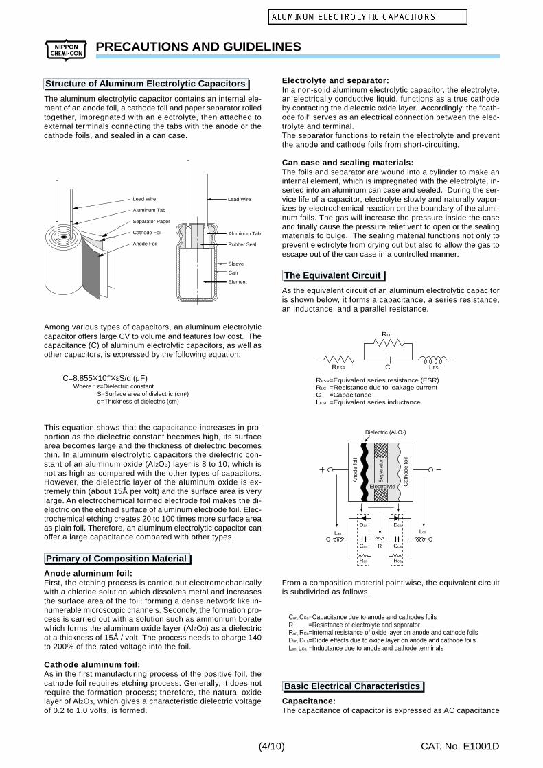
The aluminum electrolytic capacitor contains an internal ele-ment of an anode foil, a cathode foil and paper separator rolledtogether, impregnated with an electrolyte, then attached toexternal terminals connecting the tabs with the anode or thecathode foils, and sealed in a can case.
Among various types of capacitors, an aluminum electrolyticcapacitor offers large CV to volume and features low cost. Thecapacitance (C) of aluminum electrolytic capacitors, as well asother capacitors, is expressed by the following equation:
This equation shows that the capacitance increases in pro-portion as the dielectric constant becomes high, its surfacearea becomes large and the thickness of dielectric becomesthin. In aluminum electrolytic capacitors the dielectric con-stant of an aluminum oxide (Al2O3) layer is 8 to 10, which isnot as high as compared with the other types of capacitors.However, the dielectric layer of the aluminum oxide is ex-tremely thin (about 15Å per volt) and the surface area is verylarge. An electrochemical formed electrode foil makes the di-electric on the etched surface of aluminum electrode foil. Elec-trochemical etching creates 20 to 100 times more surface areaas plain foil. Therefore, an aluminum electrolytic capacitor canoffer a large capacitance compared with other types.
Anode aluminum foil:First, the etching process is carried out electromechanicallywith a chloride solution which dissolves metal and increasesthe surface area of the foil; forming a dense network like in-numerable microscopic channels. Secondly, the formation pro-cess is carried out with a solution such as ammonium boratewhich forms the aluminum oxide layer (Al2O3) as a dielectricat a thickness of 15Å / volt. The process needs to charge 140to 200% of the rated voltage into the foil.
Cathode aluminum foil:As in the first manufacturing process of the positive foil, thecathode foil requires etching process. Generally, it does notrequire the formation process; therefore, the natural oxidelayer of Al2O3, which gives a characteristic dielectric voltageof 0.2 to 1.0 volts, is formed.
Electrolyte and separator:In a non-solid aluminum electrolytic capacitor, the electrolyte,an electrically conductive liquid, functions as a true cathodeby contacting the dielectric oxide layer. Accordingly, the “cath-ode foil” serves as an electrical connection between the elec-trolyte and terminal.The separator functions to retain the electrolyte and preventthe anode and cathode foils from short-circuiting.
Can case and sealing materials:The foils and separator are wound into a cylinder to make aninternal element, which is impregnated with the electrolyte, in-serted into an aluminum can case and sealed. During the ser-vice life of a capacitor, electrolyte slowly and naturally vapor-izes by electrochemical reaction on the boundary of the alumi-num foils. The gas will increase the pressure inside the caseand finally cause the pressure relief vent to open or the sealingmaterials to bulge. The sealing material functions not only toprevent electrolyte from drying out but also to allow the gas toescape out of the can case in a controlled manner.
As the equivalent circuit of an aluminum electrolytic capacitoris shown below, it forms a capacitance, a series resistance,an inductance, and a parallel resistance.
From a composition material point wise, the equivalent circuitis subdivided as follows.
Capacitance:The capacitance of capacitor is expressed as AC capacitance
S=Surface area of dielectric (cm2)d=Thickness of dielectric (cm)
Lan
R
Dan
Can
Ran
Dca
Cca
Rca
Lca
Dielectric (Al2O3)
Sep
arat
or
Ano
de fo
il
Cat
hode
foil
Electrolyte
RLC
RESR C LESL
RESR=Equivalent series resistance (ESR)RLC =Resistance due to leakage currentC =CapacitanceLESL =Equivalent series inductance
Can, CCa=Capacitance due to anode and cathodes foilsR =Resistance of electrolyte and separatorRan, RCa=Internal resistance of oxide layer on anode and cathode foilsDan, DCa=Diode effects due to oxide layer on anode and cathode foilsLan, LCa =Inductance due to anode and cathode terminals
(4/10)
PRECAUTIONS AND GUIDELINES
CAT. No. E1001D
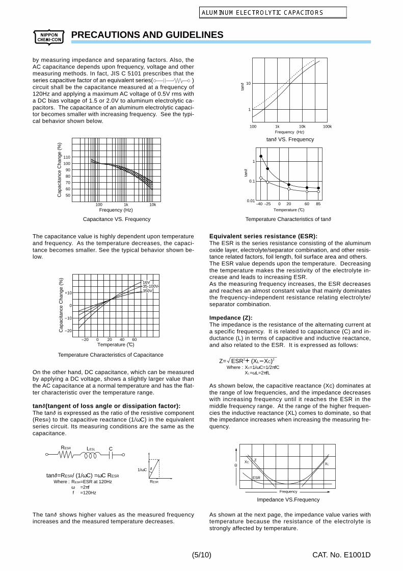
by measuring impedance and separating factors. Also, theAC capacitance depends upon frequency, voltage and othermeasuring methods. In fact, JIS C 5101 prescribes that theseries capacitive factor of an equivalent series( )circuit shall be the capacitance measured at a frequency of120Hz and applying a maximum AC voltage of 0.5V rms witha DC bias voltage of 1.5 or 2.0V to aluminum electrolytic ca-pacitors. The capacitance of an aluminum electrolytic capaci-tor becomes smaller with increasing frequency. See the typi-cal behavior shown below.
The capacitance value is highly dependent upon temperatureand frequency. As the temperature decreases, the capaci-tance becomes smaller. See the typical behavior shown be-low.
On the other hand, DC capacitance, which can be measuredby applying a DC voltage, shows a slightly larger value thanthe AC capacitance at a normal temperature and has the flat-ter characteristic over the temperature range.
tane(tangent of loss angle or dissipation factor):The tanE is expressed as the ratio of the resistive component(ResR) to the capacitive reactance (1/ωC) in the equivalentseries circuit. Its measuring conditions are the same as thecapacitance.
The tanE shows higher values as the measured frequencyincreases and the measured temperature decreases.
Equivalent series resistance (ESR):The ESR is the series resistance consisting of the aluminumoxide layer, electrolyte/separator combination, and other resis-tance related factors, foil length, foil surface area and others.The ESR value depends upon the temperature. Decreasingthe temperature makes the resistivity of the electrolyte in-crease and leads to increasing ESR.As the measuring frequency increases, the ESR decreasesand reaches an almost constant value that mainly dominatesthe frequency-independent resistance relating electrolyte/separator combination.
Impedance (Z):The impedance is the resistance of the alternating current ata specific frequency. It is related to capacitance (C) and in-ductance (L) in terms of capacitive and inductive reactance,and also related to the ESR. It is expressed as follows:
As shown below, the capacitive reactance (Xc) dominates atthe range of low frequencies, and the impedance decreaseswith increasing frequency until it reaches the ESR in themiddle frequency range. At the range of the higher frequen-cies the inductive reactance (XL) comes to dominate, so thatthe impedance increases when increasing the measuring fre-quency.
As shown at the next page, the impedance value varies withtemperature because the resistance of the electrolyte isstrongly affected by temperature.
Cap
acita
nce
Cha
nge
(%)
Frequency (Hz)
110
100
90
80
70
60
50
100 1k 10k
Capacitance VS. Frequency
Cap
acita
nce
Cha
nge
(%)
Temperature (C)
+10
0
-10
-20
-20 0 20 40 60
16V35-100V350V
Temperature Characteristics of Capacitance
RESR LESL C
RESR
1/ωC E
RESR=ESR at 120Hzω =2πf f =120Hz
Where :tanE=RESR/ (1/ωC) =ωC RESR
10
1
100 1k 10k 100kFrequency (Hz)
tanE
1
0.1
0.01-40 -25 0 20 60 85
Temperature (C)
tanE
tanE VS. Frequency
ZXC
ESR
XL
Frequency
O
XC=1/ωC=1/2πfCXL=ωL=2πfL
Where :Z= ESR2+ (XL-XC)2
Temperature Characteristics of tanE
Impedance VS.Frequency
(5/10)
PRECAUTIONS AND GUIDELINES
CAT. No. E1001D
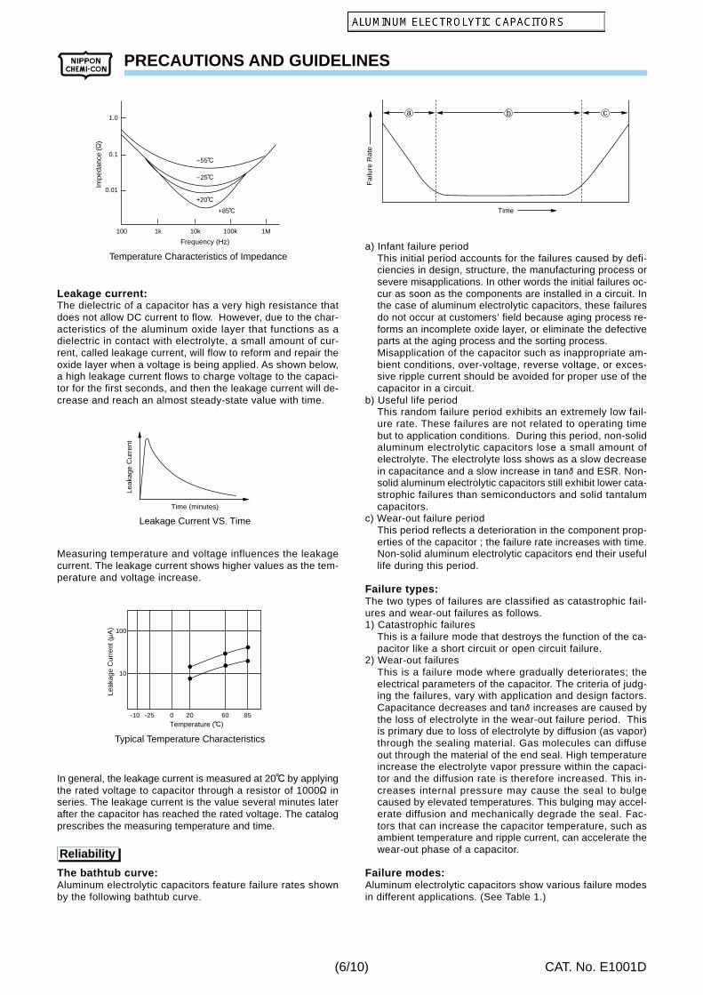
Leakage current:The dielectric of a capacitor has a very high resistance thatdoes not allow DC current to flow. However, due to the char-acteristics of the aluminum oxide layer that functions as adielectric in contact with electrolyte, a small amount of cur-rent, called leakage current, will flow to reform and repair theoxide layer when a voltage is being applied. As shown below,a high leakage current flows to charge voltage to the capaci-tor for the first seconds, and then the leakage current will de-crease and reach an almost steady-state value with time.
Measuring temperature and voltage influences the leakagecurrent. The leakage current shows higher values as the tem-perature and voltage increase.
In general, the leakage current is measured at 20C by applyingthe rated voltage to capacitor through a resistor of 1000O inseries. The leakage current is the value several minutes laterafter the capacitor has reached the rated voltage. The catalogprescribes the measuring temperature and time.
The bathtub curve:Aluminum electrolytic capacitors feature failure rates shownby the following bathtub curve.
a) Infant failure periodThis initial period accounts for the failures caused by defi-ciencies in design, structure, the manufacturing process orsevere misapplications. In other words the initial failures oc-cur as soon as the components are installed in a circuit. Inthe case of aluminum electrolytic capacitors, these failuresdo not occur at customers’ field because aging process re-forms an incomplete oxide layer, or eliminate the defectiveparts at the aging process and the sorting process.Misapplication of the capacitor such as inappropriate am-bient conditions, over-voltage, reverse voltage, or exces-sive ripple current should be avoided for proper use of thecapacitor in a circuit.
b) Useful life periodThis random failure period exhibits an extremely low fail-ure rate. These failures are not related to operating timebut to application conditions. During this period, non-solidaluminum electrolytic capacitors lose a small amount ofelectrolyte. The electrolyte loss shows as a slow decreasein capacitance and a slow increase in tanE and ESR. Non-solid aluminum electrolytic capacitors still exhibit lower cata-strophic failures than semiconductors and solid tantalumcapacitors.
c) Wear-out failure periodThis period reflects a deterioration in the component prop-erties of the capacitor ; the failure rate increases with time.Non-solid aluminum electrolytic capacitors end their usefullife during this period.
Failure types:The two types of failures are classified as catastrophic fail-ures and wear-out failures as follows.1) Catastrophic failures
This is a failure mode that destroys the function of the ca-pacitor like a short circuit or open circuit failure.
2) Wear-out failuresThis is a failure mode where gradually deteriorates; theelectrical parameters of the capacitor. The criteria of judg-ing the failures, vary with application and design factors.Capacitance decreases and tanE increases are caused bythe loss of electrolyte in the wear-out failure period. Thisis primary due to loss of electrolyte by diffusion (as vapor)through the sealing material. Gas molecules can diffuseout through the material of the end seal. High temperatureincrease the electrolyte vapor pressure within the capaci-tor and the diffusion rate is therefore increased. This in-creases internal pressure may cause the seal to bulgecaused by elevated temperatures. This bulging may accel-erate diffusion and mechanically degrade the seal. Fac-tors that can increase the capacitor temperature, such asambient temperature and ripple current, can accelerate thewear-out phase of a capacitor.
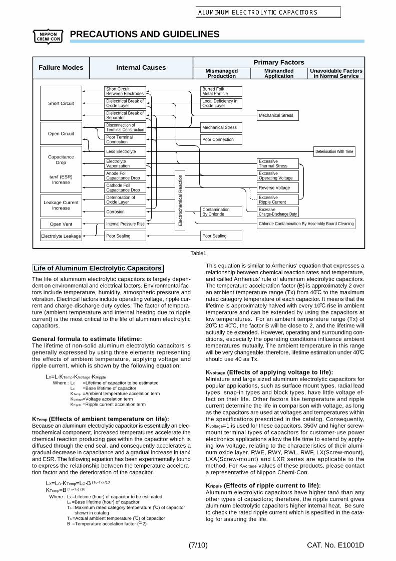
Failure modes:Aluminum electrolytic capacitors show various failure modesin different applications. (See Table 1.)
100 1k 10k 100k 1M
Frequency (Hz)
-55C
-25C
+20C
+85C
1.0
0.1
0.01
Impe
danc
e (O
)
Temperature Characteristics of Impedance
Time (minutes)
Leak
age
Cur
rent
Leakage Current VS. Time
Temperature (C)-10
10
100
-25 0 20 60 85
Leak
age
Cur
rent
(M
A)
Typical Temperature Characteristics
Time
a b c
Fai
lure
Rat
e
Reliability
(6/10)
PRECAUTIONS AND GUIDELINES
CAT. No. E1001D
This equation is similar to Arrhenius’ equation that expresses arelationship between chemical reaction rates and temperature,and called Arrhenius’ rule of aluminum electrolytic capacitors.The temperature acceleration factor (B) is approximately 2 overan ambient temperature range (Tx) from 40C to the maximumrated category temperature of each capacitor. It means that thelifetime is approximately halved with every 10C rise in ambienttemperature and can be extended by using the capacitors atlow temperatures. For an ambient temperature range (Tx) of20C to 40C, the factor B will be close to 2, and the lifetime willactually be extended. However, operating and surrounding con-ditions, especially the operating conditions influence ambienttemperatures mutually. The ambient temperature in this rangewill be very changeable; therefore, lifetime estimation under 40Cshould use 40 as Tx.
Kvoltage (Effects of applying voltage to life):Miniature and large sized aluminum electrolytic capacitors forpopular applications, such as surface mount types, radial leadtypes, snap-in types and block types, have little voltage ef-fect on their life. Other factors like temperature and ripplecurrent determine the life in comparison with voltage, as longas the capacitors are used at voltages and temperatures withinthe specifications prescribed in the catalog. Consequently,Kvoltage=1 is used for these capacitors. 350V and higher screw-mount terminal types of capacitors for customer-use powerelectronics applications allow the life time to extend by apply-ing low voltage, relating to the characteristics of their alumi-num oxide layer. RWE, RWY, RWL, RWF, LX(Screw-mount),LXA(Screw-mount) and LXR series are applicable to themethod. For Kvoltage values of these products, please contacta representative of Nippon Chemi-Con.
Kripple (Effects of ripple current to life):Aluminum electrolytic capacitors have higher tanE than anyother types of capacitors; therefore, the ripple current givesaluminum electrolytic capacitors higher internal heat. Be sureto check the rated ripple current which is specified in the cata-log for assuring the life.
The life of aluminum electrolytic capacitors is largely depen-dent on environmental and electrical factors. Environmental fac-tors include temperature, humidity, atmospheric pressure andvibration. Electrical factors include operating voltage, ripple cur-rent and charge-discharge duty cycles. The factor of tempera-ture (ambient temperature and internal heating due to ripplecurrent) is the most critical to the life of aluminum electrolyticcapacitors.
General formula to estimate lifetime:The lifetime of non-solid aluminum electrolytic capacitors isgenerally expressed by using three elements representingthe effects of ambient temperature, applying voltage andripple current, which is shown by the following equation:
KTemp (Effects of ambient temperature on life):Because an aluminum electrolytic capacitor is essentially an elec-trochemical component, increased temperatures accelerate thechemical reaction producing gas within the capacitor which isdiffused through the end seal, and consequently accelerates agradual decrease in capacitance and a gradual increase in tanEand ESR. The following equation has been experimentally foundto express the relationship between the temperature accelera-tion factor and the deterioration of the capacitor.
Failure Modes Internal CausesPrimary Factors
MismanagedProduction
MishandledApplication
Unavoidable Factorsin Normal Service
Short Circuit
Poor TerminalConnection
Less Electrolyte
ElectrolyteVaporization
Anode FoilCapacitance Drop
Cathode FoilCapacitance Drop
Deterioration ofOxide Layer
Corrosion
Internal Pressure RiseOpen Vent
Electrolyte Leakage Poor Sealing
Disconnection ofTerminal Construction
Dielectrical Break ofSeparator
Short CircuitBetween Electrodes
Burred Foil/Metal Particle
Local Deficiency inOxide Layer
Mechanical Stress
ExcessiveThermal Stress
Deterioration With Time
ExcessiveOperating Voltage
Reverse Voltage
ExcessiveRipple Current
ExcessiveCharge-Discharge Duty
Chloride Contamination By Assembly Board Cleaning
Mechanical Stress
Poor Connection
Poor Sealing
ContaminationBy Chloride
Dielectrical Break ofOxide Layer
Open Circuit
Leakage CurrentIncrease
CapacitanceDrop
tanE (ESR)Increase
Ele
ctro
chem
ical
Rea
ctio
n
LX =Lifetime of capacitor to be estimatedLo =Base lifetime of capacitorKTemp =Ambient temperature accelation termKVoltage=Voltage accelation termKRipple =Ripple current accelation term
Where :LX=L·KTemp·KVoltage·KRipple
LX =Lifetime (hour) of capacitor to be estimatedLo =Base lifetime (hour) of capacitorTo =Maximum rated category temperature (C) of capacitor shown in catalogTX =Actual ambient temperature (C) of capacitorB =Temperature accelation factor ( 2)
Where :
LX=LO·KTemp=LO·B (TO-TX) /10
KTemp=B (TO-TX) /10
~~
Table1
Life of Aluminum Electrolytic Capacitors
(7/10)
PRECAUTIONS AND GUIDELINES
CAT. No. E1001D
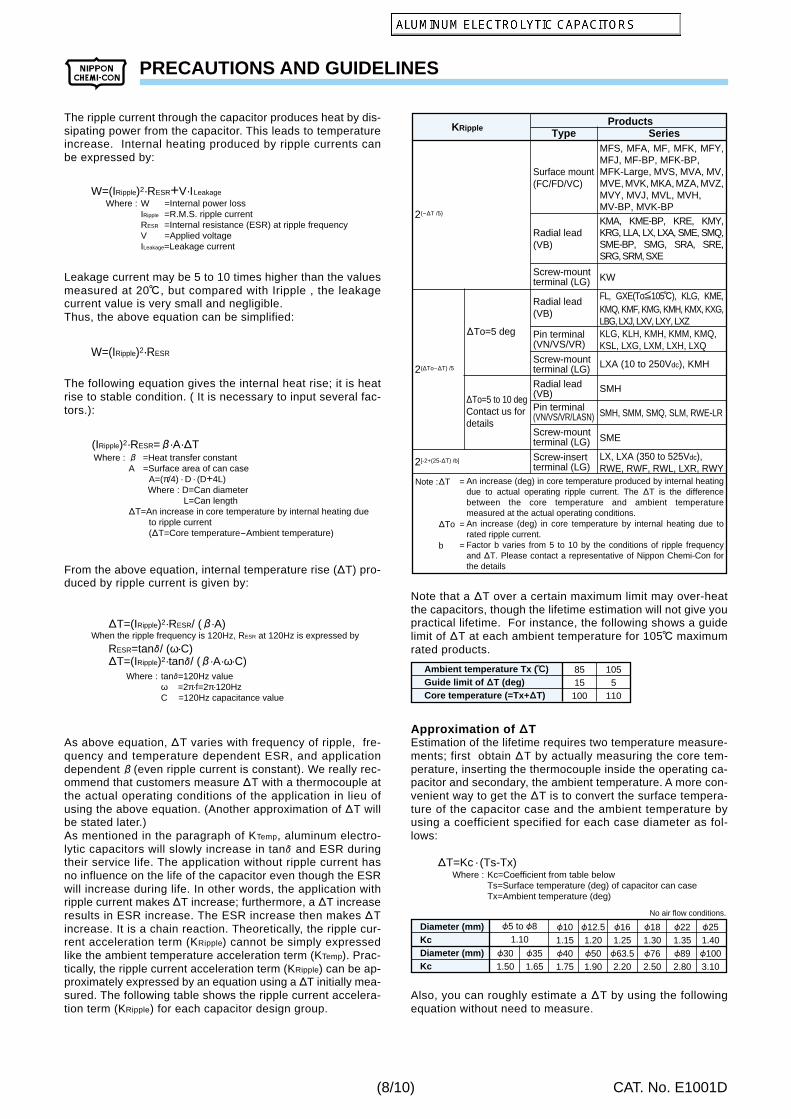
The ripple current through the capacitor produces heat by dis-sipating power from the capacitor. This leads to temperatureincrease. Internal heating produced by ripple currents canbe expressed by:
Leakage current may be 5 to 10 times higher than the valuesmeasured at 20C , but compared with Iripple , the leakagecurrent value is very small and negligible.Thus, the above equation can be simplified:
The following equation gives the internal heat rise; it is heatrise to stable condition. ( It is necessary to input several fac-tors.):
From the above equation, internal temperature rise (DT) pro-duced by ripple current is given by:
As above equation, DT varies with frequency of ripple, fre-quency and temperature dependent ESR, and applicationdependent (even ripple current is constant). We really rec-ommend that customers measure DT with a thermocouple atthe actual operating conditions of the application in lieu ofusing the above equation. (Another approximation of DT willbe stated later.)As mentioned in the paragraph of KTemp, aluminum electro-lytic capacitors will slowly increase in tanE and ESR duringtheir service life. The application without ripple current hasno influence on the life of the capacitor even though the ESRwill increase during life. In other words, the application withripple current makes DT increase; furthermore, a DT increaseresults in ESR increase. The ESR increase then makes DTincrease. It is a chain reaction. Theoretically, the ripple cur-rent acceleration term (KRipple) cannot be simply expressedlike the ambient temperature acceleration term (KTemp). Prac-tically, the ripple current acceleration term (KRipple) can be ap-proximately expressed by an equation using a DT initially mea-sured. The following table shows the ripple current accelera-tion term (KRipple) for each capacitor design group.
Note that a DT over a certain maximum limit may over-heatthe capacitors, though the lifetime estimation will not give youpractical lifetime. For instance, the following shows a guidelimit of DT at each ambient temperature for 105C maximumrated products.
Approximation of dTEstimation of the lifetime requires two temperature measure-ments; first obtain DT by actually measuring the core tem-perature, inserting the thermocouple inside the operating ca-pacitor and secondary, the ambient temperature. A more con-venient way to get the DT is to convert the surface tempera-ture of the capacitor case and the ambient temperature byusing a coefficient specified for each case diameter as fol-lows:
Also, you can roughly estimate a DT by using the followingequation without need to measure.
W =Internal power lossIRipple =R.M.S. ripple currentRESR =Internal resistance (ESR) at ripple frequencyV =Applied voltageILeakage=Leakage current
Where :W=(IRipple)2·RESR+V·ILeakage
W=(IRipple)2·RESR
=Heat transfer constantA =Surface area of can case A=(π/4) · D · (D+4L) Where : D=Can diameter L=Can length DT=An increase in core temperature by internal heating due to ripple current (DT=Core temperature-Ambient temperature)
Where :(IRipple)2·RESR= ·A·DT
tanE=120Hz valueω =2π·f=2π·120HzC =120Hz capacitance value
Where :
When the ripple frequency is 120Hz, RESR at 120Hz is expressed byDT=(IRipple)2·RESR/ ( ·A)
An increase (deg) in core temperature produced by internal heating due to actual operating ripple current. The DT is the difference between the core temperature and ambient temperature measured at the actual operating conditions.An increase (deg) in core temperature by internal heating due to rated ripple current.Factor b varies from 5 to 10 by the conditions of ripple frequency and DT. Please contact a representative of Nippon Chemi-Con for the details
Ambient temperature Tx (c)Guide limit of dT (deg)Core temperature (=Tx+dT)
8515100
1055
110
Kc=Coefficient from table belowTs=Surface temperature (deg) of capacitor can caseTx=Ambient temperature (deg)
Where :DT=Kc · (Ts-Tx)
Diameter (mm)KcDiameter (mm)Kc
F101.15F401.75
F301.50
F351.65
F5 to F81.10
F12.51.20F501.90
F161.25F63.52.20
F181.30F762.50
F221.35F892.80
F251.40F1003.10
No air flow conditions.
(8/10)
PRECAUTIONS AND GUIDELINES
CAT. No. E1001D
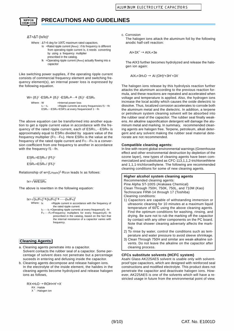
Like switching power supplies, if the operating ripple currentconsists of commercial frequency element and switching fre-quency element(s), an internal power loss is expressed bythe following equation.
The above equation can be transformed into another equa-tion to get a ripple current value in accordance with the fre-quency of the rated ripple current, each of ESRf1,···ESRfn isapproximately equal to ESRf0 divided by square value of thefrequency multiplier (Ff1···Ffn). Here ESRf0 is the value at thefrequency of the rated ripple current and Ff1···Ffn is a conver-sion coefficient from one frequency to another in accordancewith the frequency f1···fn.
Relationship of w=(LRipple)2·RESR leads lx as follows:
The above is rewritten in the following equation:
a. Cleaning agents penetrate into a capacitor.Solvent contacts the rubber seal of a capacitor. Some per-centage of solvent does not penetrate but a percentagesuceeds in entering and defusing inside the capacitor.
b. Cleaning agents decompose and release halogen ions.In the electrolyte of the inside element, the halides in thecleaning agents become hydrolyzed and release halogenions as follows,
c. CorrosionThe halogen ions attack the aluminum foil by the followinganodic half-cell reaction:
The AlX3 further becomes hydrolyzed and release the halo-gen ion again:
The halogen ions release by this hydrolysis reaction furtherattacks the aluminum according to the previous reaction for-mula, and these reactions are repeated and accelerated whenvoltage and temperature is applied. Also, the hydrogen ionsincrease the local acidity which causes the oxide dielectric todissolve. Thus, localized corrosion accelerates to corrode boththe aluminum metal and the dielectric. In addition, a terpeneor petroleum system cleaning solvent will be absorbed intothe rubber seal of the capacitor. The rubber seal finally weak-ens. An alkaline saponification detergent will damage the alu-minum metal and marking. In summary, recommended clean-ing agents are halogen free. Terpene, petroleum, alkali deter-gent and any solvent making the rubber seal material dete-riorate are not recommended.
Compatible cleaning agents:In line with recent global environmental warnings (Greenhouseeffect and other environmental destruction by depletion of theozone layer), new types of cleaning agents have been com-mercialized and substituted as CFC-113,1,1,2-trichloroethleneand 1,1,1-trichloroethylene. The following are recommendedcleaning conditions for some of new cleaning agents.
Higher alcohol system cleaning agentsRecommended cleaning agents:Pine Alpha ST-100S (Arakawa Chemical)Clean Through 750H, 750K, 750L, and 710M (Kao)Technocare FRW-14 through 17 (Toshiba)Cleaning conditions:1) Capacitors are capable of withstanding immersion or
ultrasonic cleaning for 10 minutes at a maximum liquidtemperature of 60C using the above cleaning agents.Find the optimum conditions for washing, rinsing, anddrying. Be sure not to rub the marking off the capacitorby contact with any other components on the PC board.Note that shower cleaning adversely affects the mark-ing.
2) To rinse by water, control the conditions such as tem-perature and water pressure to avoid sleeve shrinkage.
3) Clean Through 750H and similar are weak-alkaline sol-vents. Do not leave the alkaline on the capacitor aftercleaning process.
CFCs substitute solvents (HCFC system)Asahi Glass AK225AES solvent is usable only with solvent-proof type capacitors, which are designed with reinforced sealconstructions and modified electrolyte. This product does notpenetrate the capacitor and deactivate halogen ions. How-ever, AK225AES is one of the solvents which will have a re-stricted usage in future from the environmental point of view.
DT=5 deg for 105C maximum rated capacitors.Io =Rated ripple current (ARMS) : if its frequency is different from operating ripple current Ix, it needs converting by using a frequency multiplier prescribed in the catalog.lk =Operating ripple current (ARMS) actually flowing into a capacitor
Where :
DT=DT·(Ix/Io)2
W =Internal power lossIf1···If1 =Ripple currents at every frequencies f1···fnESRf1···ESRfn=ESR's at every frequenciesf 1···fn
Ix =Ripple current in accordance with the frequency of the rated ripple current
If1······Ifn =Operating ripple currents at every frequencyf1···fnFf1······Ffn=Frequency multipliers for every frequencyf1···fn
prescribed in the catalog, based on the fact that the internal resistance of a capacitor varies with frequency.
RX : HalideX - : Halogen ion
RX+H2O ROH+H++X-
AI+3X- AIX3+3e
AIX3+3H2O AI (OH)3+3H++3X-
Cleaning Agents
(9/10)
PRECAUTIONS AND GUIDELINES
CAT. No. E1001D
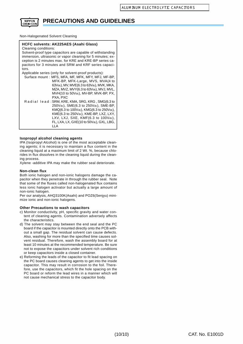
Non-Halogenated Solvent Cleaning
HCFC solvents: AK225AES (Asahi Glass)Cleaning conditions:Solvent-proof type capacitors are capable of withstandingimmersion, ultrasonic or vapor cleaning for 5 minutes; ex-ception is 2 minutes max. for KRE and KRE-BP series ca-pacitors for 3 minutes and SRM and KRF series capaci-tors.Applicable series (only for solvent-proof products):
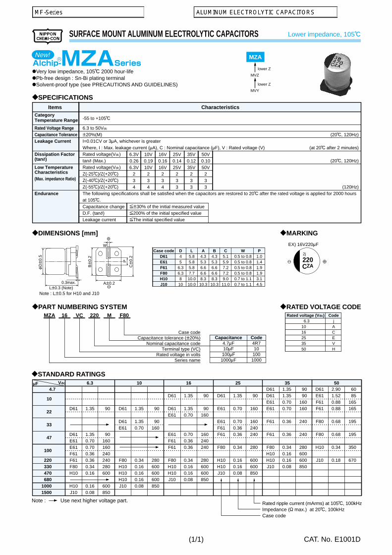
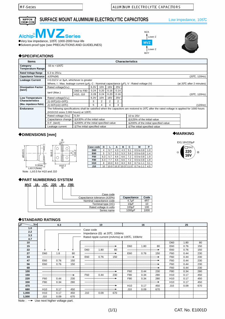
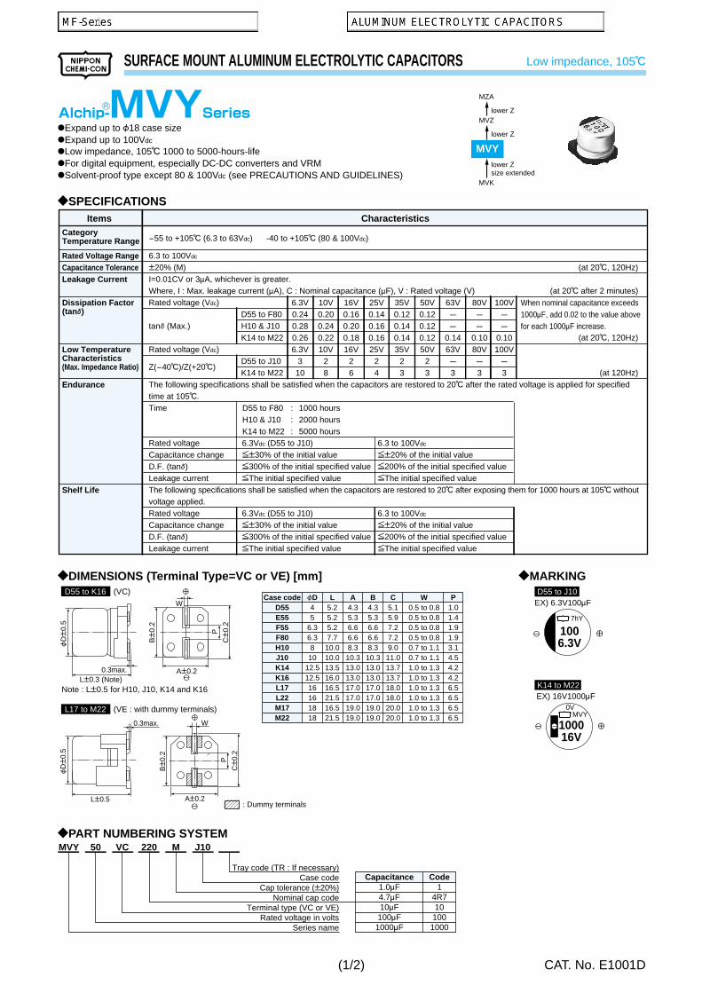
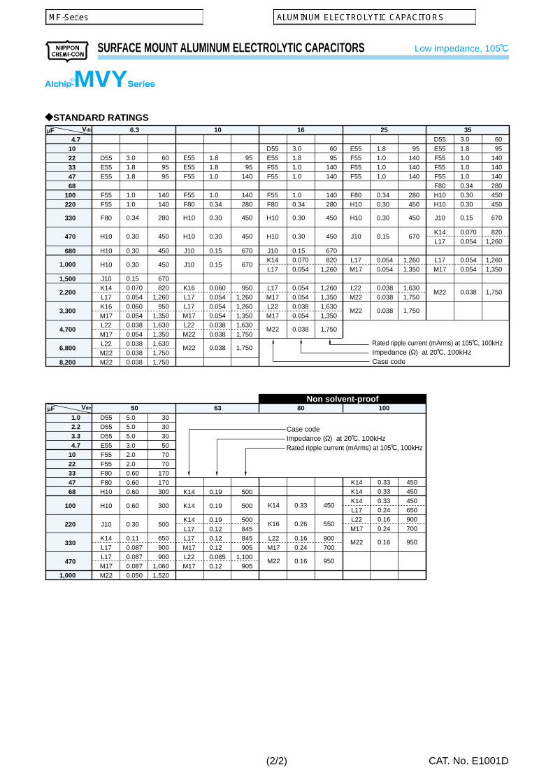
Surface mount : MFS, MFA, MF, MFK, MFY, MFJ, MF-BP,MFK-BP, MFK-Large, MVS, MVA(4 to63Vdc), MV, MVE(6.3 to 63Vdc), MVK, MKA,MZA, MVZ, MVY(6.3 to 63Vdc), MVJ, MVL,MVH(10 to 50Vdc), MV-BP, MVK-BP, PX,PXA, PXC
R a d i a l l e a d : SRM, KRE, KMA, SRG, KRG , SMG(6.3 to250Vdc), SME(6.3 to 250Vdc), SME-BP,KMQ(6.3 to 100Vdc), KMG(6.3 to 250Vdc),KME(6.3 to 250Vdc), KME-BP, LXZ, LXY,LXV, LXJ, SXE, KMF(6.3 to 100Vdc),FL, LXA, LX, GXE(10 to 50Vdc), GXL, LBG,LLA
Isopropyl alcohol cleaning agentsIPA (Isopropyl Alcohol) is one of the most acceptable clean-ing agents; it is necessary to maintain a flux content in thecleaning liquid at a maximum limit of 2 Wt. %, because chlo-rides in flux dissolves in the cleaning liquid during the clean-ing process.Xylene -additive IPA may make the rubber seal deteriorate.
Non-clean fluxBoth ionic halogen and non-ionic halogens damage the ca-pacitor when they penetrate in through the rubber seal. Notethat some of the fluxes called non-halogenated flux containsless ionic halogen activator but actually a large amount ofnon-ionic halogen.Per our analysis, AHQ3100K(Asahi) and POZ6(Senjyu) mini-mize ionic and non-ionic halogens.
Other Precautions to wash capacitorsc) Monitor conductivity, pH, specific gravity and water con-
tent of cleaning agents. Contamination adversely affectsthe characteristics.
d) The solvent may stay between the end seal and the PCboard if the capacitor is mounted directly onto the PCB with-out a small gap. The residual solvent can cause defects.Also, washing for more than the specified time causes sol-vent residual. Therefore, wash the assembly board for atleast 10 minutes at the recommended temperature. Be surenot to expose the capacitors under solvent rich conditionsor keep capacitors inside a closed container.
e) Reforming the leads of the capacitor to fit lead spacing onthe PC board causes cleaning agents to get into the insidecapacitor. This may result in corrosion to the foil. There-fore, use the capacitors, which fit the hole spacing on thePC board or reform the lead wires in a manner which willnot cause mechanical stress to the capacitor body.
(10/10)
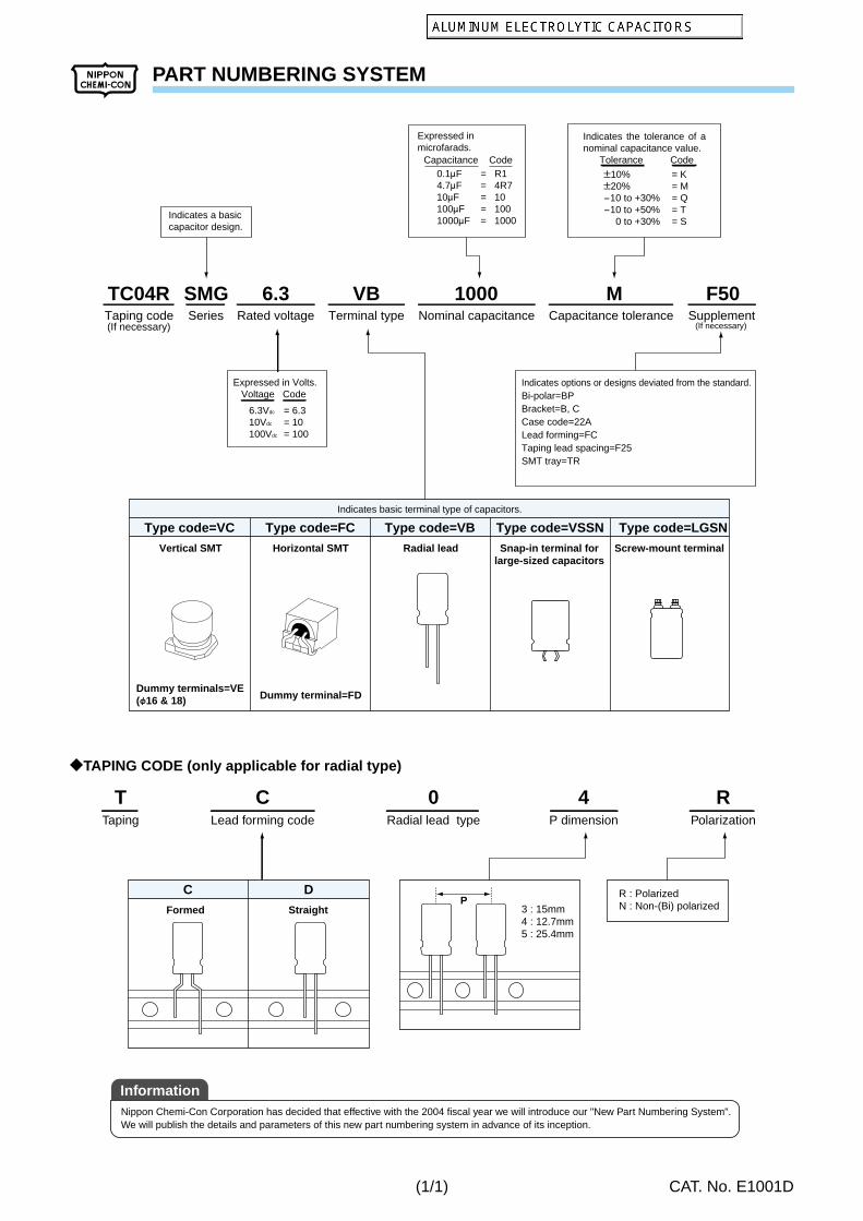
PART NUMBERING SYSTEM
CAT. No. E1001D
Indicates the tolerance of a nominal capacitance value. Tolerance Code
P10%P20%-10 to +30%-10 to +50% 0 to +30%
= K= M= Q= T= S
Indicates options or designs deviated from the standard.Bi-polar=BPBracket=B, CCase code=22ALead forming=FCTaping lead spacing=F25SMT tray=TR
Expressed inmicrofarads.
Capacitance Code0.1MF4.7MF10MF100MF1000MF
= R1= 4R7= 10= 100= 1000Indicates a basic
capacitor design.
Expressed in Volts. Voltage Code
6.3Vdc
10Vdc
100Vdc
= 6.3= 10= 100
Indicates basic terminal type of capacitors.
Type code=VBType code=FCType code=VC Type code=VSSN Type code=LGSN
Radial leadHorizontal SMTVertical SMT
Dummy terminal=FDDummy terminals=VE(f16 & 18)
Snap-in terminal forlarge-sized capacitors
Screw-mount terminal
TC04R SMG 6.3 VB 1000 M F50Taping code(If necessary)
Series Rated voltage Terminal type Nominal capacitance Capacitance tolerance Supplement(If necessary)
3 : 15mm4 : 12.7mm5 : 25.4mm
R : PolarizedN : Non-(Bi) polarized
DC
Formed Straight
Taping Lead forming code Radial lead type P dimension Polarization
T C 0 4 R
P
?TAPING CODE (only applicable for radial type)
Nippon Chemi-Con Corporation has decided that effective with the 2004 fiscal year we will introduce our "New Part Numbering System".We will publish the details and parameters of this new part numbering system in advance of its inception.
Information
(1/1)
ENVIRONMENTAL CONSIDERATION
CAT. No. E1001D
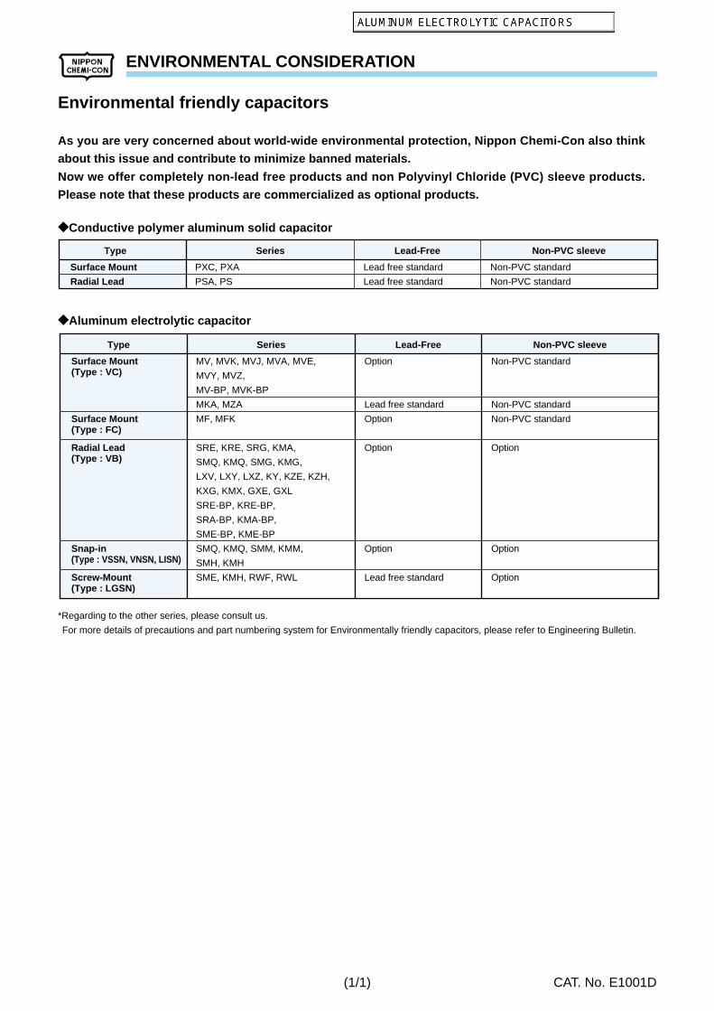
As you are very concerned about world-wide environmental protection, Nippon Chemi-Con also think
about this issue and contribute to minimize banned materials.
Now we offer completely non-lead free products and non Polyvinyl Chloride (PVC) sleeve products.
Please note that these products are commercialized as optional products.
Environmental friendly capacitors
?Conductive polymer aluminum solid capacitor
?Aluminum electrolytic capacitor
*Regarding to the other series, please consult us.
For more details of precautions and part numbering system for Environmentally friendly capacitors, please refer to Engineering Bulletin.
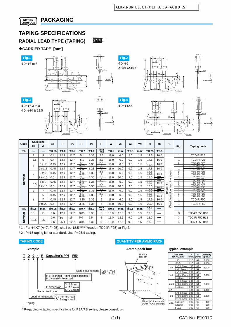
R : Polarized (Right lead is positive.)N : Non (Bi)-Polarized
3 : 15mm4 : 12.7mm5 : 25.4mmRadial lead type
Taping
Lead spacing code F25 : F=2.5F50 : F=5.0
Lead forming code C : Formed leadD : Straight lead
P dimension
* Regarding to taping specifications for PSA/PS series, please consult us.
Case sizefD L(mm)
F3 3,0003,000
1,000
500
F3.5
F7
F12.5
F4 2,000
2,000
2,000
F5
F6.3
F10
F8 1,000
A(mm)
B(mm)
Quantity(pcs.)
L=5 & 7mmL=11.5mmL=5 & 7mmL=9 to 15mm
L=5 & 7mmL=9 to 15mm
L=5 & 7mmL=9 to 15mmL=17 & 20mmL[25mmL]30mm
216 424242514251
4251
42425153626767
216183183232232
L=17mm 53235282284
L=17mm 55284183232232235308308308
800500
P2
P1
P0
P
W
0.7P
0.2
A
H
H1
H0 W
2W
0 W1
F
FD
Fd
1.0max.
Base tape Adhesive tape
P2.0
1.0max.
4.0P0.2
P2
P1
P0
P
W
0.7P
0.2
A
H
H1
W2
W0 W
1
F
FD
Fd
4.0P0.2Base tape
Adhesive tape
P2.0
1.0max.
1.0max.
P2
P1
P0
P
W
0.7P
0.2
A
H
H1
W2
W0 W
1
F
FD
Fd
4.0P0.2
1.0max.
Base tapeAdhesive tape
P2.0
1.0max.
P2
P1
P0
P
W
0.7P
0.2
A
H
H1
W2
W0 W
1
F
FD
Fd
4.0P0.2
1.0max.
Base tape Adhesive tape
P2.0
1.0max.
Line fortear-off
A
328mm (FD=8 and smaller)340mm (FD=10 and larger)
B
* 1 : For F4b7 (A=7, F=25), shall be 18.5-0.5/+0.75 (code : TD04R F25) at Fig.2.
* 2 : P=15 taping is not standard. Use P=25.4 taping.
Example Ammo pack box Typical example
TAPING CODE QUANTITY PER AMMO PACK
?CARRIER TAPE [mm]
RADIAL LEAD TYPE (TAPING)
(1/1)
PACKAGING
CAT. No. E1001D
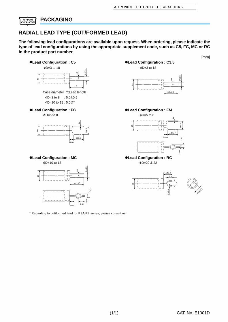
The following lead configurations are available upon request. When ordering, please indicate thetype of lead configurations by using the appropriate supplement code, such as C5, FC, MC or RCin the product part number.
@Lead Configuration : FC @Lead Configuration : FM
@Lead Configuration : MC @Lead Configuration : RC
5P0.5
2max.
PP
0.5
FD
Fd
4.5
2max.
PP
0.5
FD
Fd
+1.0-0
4.5
PP
0.5
FD
Fd
+1.0-0
(1.1
)1m
ax.
(1.1
)
1max
.
(2.5)2max.
4.0P1.0
FD
Fd=
1.0
2.8
10.5P0
.5
2.4
3.5P0.5
PP
0.5
FD
Fd
CPP
0.5
FD
Fd
@Lead Configuration : C5 @Lead Configuration : C3.5FD=3 to 18 FD=3 to 18
FD=5 to 8 FD=5 to 8
FD=10 to 18 FD=20 & 22
FD=3 to 8 : 5.0P0.5
FD=10 to 18 : 5.0
Case diameter C:Lead length
+1.0-0
[mm]
RADIAL LEAD TYPE (CUT/FORMED LEAD)
* Regarding to cut/formed lead for PSA/PS series, please consult us.
(1/1)
ALUMINUM ELECTROLYTIC CAPACITORS AVAILABLE TERMINAL FOR SNAP-IN TYPE
CAT. No. E1001D
t=0.7
1.5P0.15.
5P1Edge of
can
VR pin Dimensions
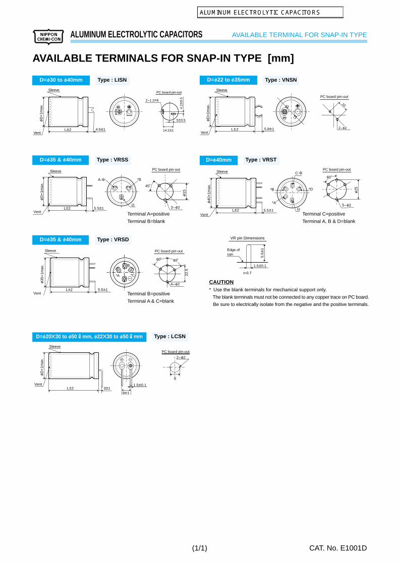
AVAILABLE TERMINALS FOR SNAP-IN TYPE [mm]
CAUTION* Use the blank terminals for mechanical support only.
The blank terminals must not be connected to any copper trace on PC board.
Be sure to electrically isolate from the negative and the positive terminals.
D=f35 & f40mm Type : VRSS
45
3-F2
F1
5
PC board pin-out
LP2
FD
+1m
ax.
5.5P1Vent
Sleeve
*BA:
Terminal A=positive
Terminal B=blank
D=f22 to f35mm Type : VNSN
Sleeve
Vent5.8P1LP2
FD
+1m
ax.
PC board pin-out
10
2-F2
Sleeve
Vent
F35
+1m
ax.
5.5P1LP2
*A
B
*C
D=f35 & f40mm Type : VRSD
PC board pin-out
22.5
4-F2
6060
Terminal B=positive
Terminal A & C=blank
D=f40mm Type : VRST
5-F2
F25
PC board pin-out
60C:
LP2F
40+
1max
.5.5P1
Vent
Sleeve
*D*B
*A
Terminal C=positive
Terminal A, B & D=blank
D=f30 to f40mm Type : LISN
Sleeve
Vent4.5P1LP2
FD
+1m
ax.
PC board pin-out
2-1.2B6
5P0.5
14.2P1
4.2P
0.5
D=f20b30 to f50 r mm, f22b30 to f50 r mm Type : LCSN
Sleeve
FD
+1m
ax.
Vent3P1LP2
8P1
1.5P0.1
8
2-F2
PC board pin-out
(1/1)
CONDUCTIVE POLYMER ALUMINUM SOLID CAPACITORS Surface Mount
CAT. No. E1001D
c
bb aSolder land on PC board
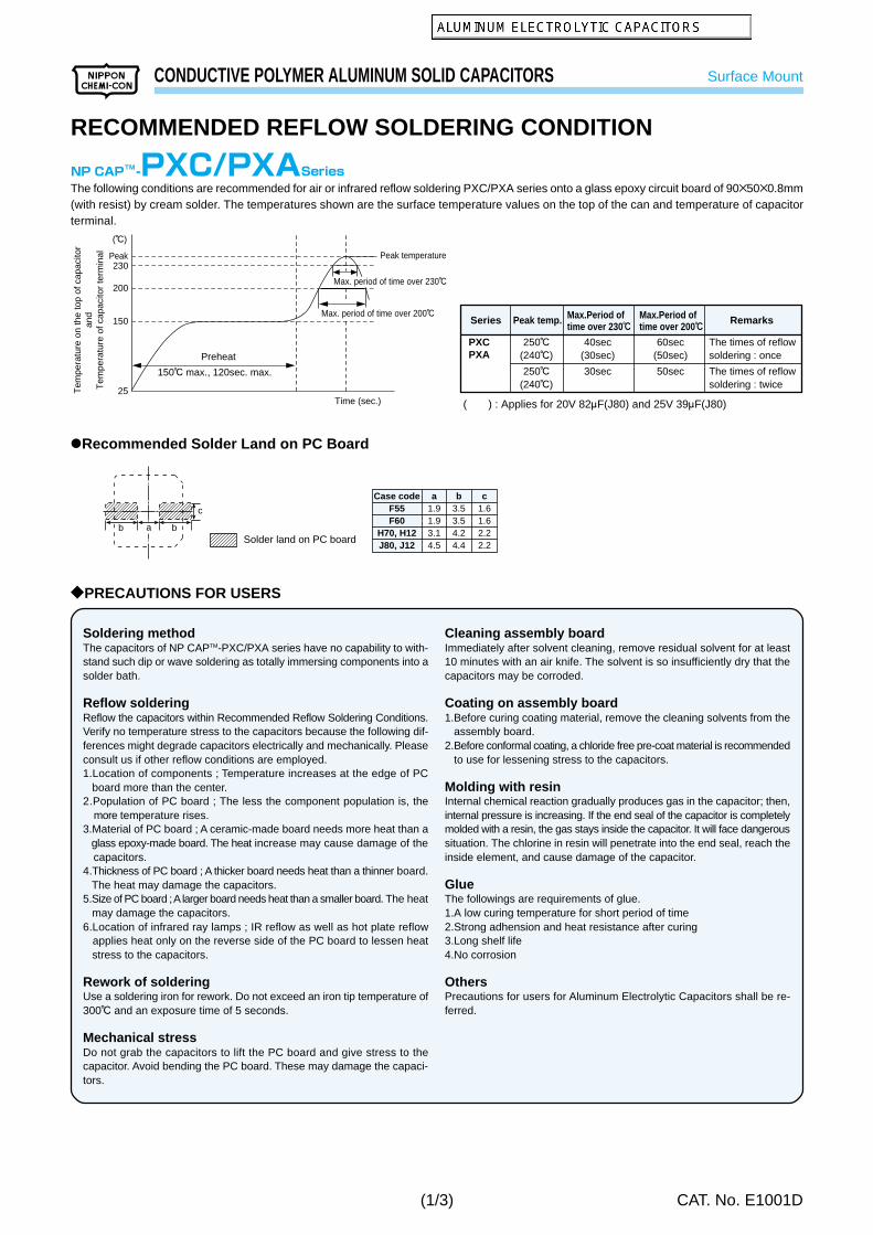
@Recommended Solder Land on PC Board
Case codeF55F60
H70, H12J80, J12
a1.91.93.14.5
b3.53.54.24.4
c1.61.62.22.2
The following conditions are recommended for air or infrared reflow soldering PXC/PXA series onto a glass epoxy circuit board of 90B50B0.8mm(with resist) by cream solder. The temperatures shown are the surface temperature values on the top of the can and temperature of capacitorterminal.
200
230Peak
150
25
Preheat
150C max., 120sec. max.
Peak temperature
Time (sec.)
Max. period of time over 200C
Max. period of time over 230C
(C)
Tem
pera
ture
on
the
top
of c
apac
itor
and
Tem
pera
ture
of c
apac
itor
term
inal
Cleaning assembly boardImmediately after solvent cleaning, remove residual solvent for at least10 minutes with an air knife. The solvent is so insufficiently dry that thecapacitors may be corroded.
Coating on assembly board1.Before curing coating material, remove the cleaning solvents from the assembly board.2.Before conformal coating, a chloride free pre-coat material is recommended to use for lessening stress to the capacitors.
Molding with resinInternal chemical reaction gradually produces gas in the capacitor; then,internal pressure is increasing. If the end seal of the capacitor is completelymolded with a resin, the gas stays inside the capacitor. It will face dangeroussituation. The chlorine in resin will penetrate into the end seal, reach theinside element, and cause damage of the capacitor.
GlueThe followings are requirements of glue.1.A low curing temperature for short period of time2.Strong adhension and heat resistance after curing3.Long shelf life4.No corrosion
OthersPrecautions for users for Aluminum Electrolytic Capacitors shall be re-ferred.
Soldering methodThe capacitors of NP CAPTM-PXC/PXA series have no capability to with-stand such dip or wave soldering as totally immersing components into asolder bath.
Reflow solderingReflow the capacitors within Recommended Reflow Soldering Conditions.Verify no temperature stress to the capacitors because the following dif-ferences might degrade capacitors electrically and mechanically. Pleaseconsult us if other reflow conditions are employed.1.Location of components ; Temperature increases at the edge of PC board more than the center.2.Population of PC board ; The less the component population is, the more temperature rises.3.Material of PC board ; A ceramic-made board needs more heat than a glass epoxy-made board. The heat increase may cause damage of the capacitors.4.Thickness of PC board ; A thicker board needs heat than a thinner board. The heat may damage the capacitors.5.Size of PC board ; A larger board needs heat than a smaller board. The heat may damage the capacitors.6.Location of infrared ray lamps ; IR reflow as well as hot plate reflow applies heat only on the reverse side of the PC board to lessen heat stress to the capacitors.
Rework of solderingUse a soldering iron for rework. Do not exceed an iron tip temperature of300C and an exposure time of 5 seconds.
Mechanical stressDo not grab the capacitors to lift the PC board and give stress to thecapacitor. Avoid bending the PC board. These may damage the capaci-tors.
?PRECAUTIONS FOR USERS
250C(240C)
250C(240C)
40sec(30sec)
30sec
60sec(50sec)
50sec
The times of reflow soldering : once
The times of reflow soldering : twice
PXCPXA
( ) : Applies for 20V 82MF(J80) and 25V 39MF(J80)
Series Peak temp. RemarksMax.Period of time over 230c
Max.Period of time over 200c
RECOMMENDED REFLOW SOLDERING CONDITION
(1/3)
SURFACE MOUNT ALUMINUM ELECTROLYTIC CAPACITORS Surface Mount
CAT. No. E1001D
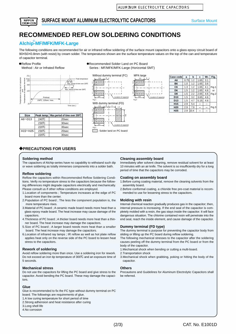
RECOMMENDED REFLOW SOLDERING CONDITIONSAlchip-MF/MFK/MFK-LargeThe following conditions are recommended for air or infrared reflow soldering of the surface mount capacitors onto a glass epoxy circuit board of90B50B0.8mm (with resist) by cream solder. The temperatures shown are the surface temperature values on the top of the can and temperatureof capacitor terminal.
200
230Peak
150
25
Preheat
150C, 120sec. max.
Peak temperature
Time (sec.)
Max. period of time over 200C
Max. period of time over 230C
(C)
Tem
pera
ture
on
the
top
of c
apac
itor
and
Tem
pera
ture
of c
apac
itor
term
inal
R
Case codeA6B6C6D6D8
D10D13H15H20H25
a 0.75
1.01.31.51.51.51.52.92.92.9
b1.21.21.21.22.23.24.75.47.9
10.4
c1.651.651.651.652.653.655.15---
W1
3.13.64.14.64.64.64.6---
Fig.
Fig.1or
Fig.2
Fig.3
@Recommended Solder Land on PC Board Series : MF/MFK/MFK-Large (Horizontal SMT)
?PRECAUTIONS FOR USERS
Cleaning assembly boardImmediately after solvent cleaning, remove residual solvent for at least10 minutes with an air knife. The solvent is so insufficiently dry for a longperiod of time that the capacitors may be corroded.
Coating on assembly board1.Before curing coating material, remove the cleaning solvents from the
assembly board.2.Before conformal coating, a chloride free pre-coat material is recom-
mended to use for lessening stress to the capacitors.
Molding with resinInternal chemical reaction gradually produces gas in the capacitor; then,internal pressure is increasing. If the end seal of the capacitor is com-pletely molded with a resin, the gas stays inside the capacitor. It will facedangerous situation. The chlorine contained resin will penetrate into theend seal, reach the inside element, and cause damage of the capacitor.
Dummy terminal (FD type)The dummy terminal is purpose for preventing the capacitor body fromsliding or lifting up the PC board during reflow soldering.The following mechanical stresses to the capacitor after the solderingcauses peeling off the dummy terminal from the PC board or from thebody of the capacitor.1.Mechanical shock when bending or cutting a multi-board.2.Transportation shock3.Mechanical shock when grabbing, poking or hitting the body of the
capacitor.
OthersPrecautions and Guidelines for Aluminum Electrolytic Capacitors shallbe referred.
Soldering methodThe capacitors of Alchip-series have no capability to withstand such dipor wave soldering as totally immerses components into a solder bath.
Reflow solderingReflow the capacitors within Recommended Reflow Soldering Condi-tions. Verify no temperature stress to the capacitors because the follow-ing differences might degrade capacitors electrically and mechanically.Please consult us if other reflow conditions are employed.1.Location of components ; Temperature increases at the edge of PC board more than the center.2.Population of PC board ; The less the component population is, the more temperature rises.3.Material of PC board ; A ceramic made board needs more heat than a glass epoxy made board. The heat increase may cause damage of the capacitors.4.Thickness of PC board ; A thicker board needs more heat than a thin-
ner board. The heat increase may damage the capacitors.5.Size of PC board ; A larger board needs more heat than a smaller board. The heat increase may damage the capacitors.6.Location of infrared ray lamps ; IR reflow as well as hot plate reflow applies heat only on the reverse side of the PC board to lessen heat stress to the capacitors.
Rework of solderingAvoid reflow soldering more than once. Use a soldering iron for rework.Do not exceed an iron tip temperature of 300C and an exposure time of5 seconds.
Mechanical stressDo not use the capacitors for lifting the PC board and give stress to thecapacitor. Avoid bending the PC board. These may damage the capaci-tors.
GlueGlue is recommended to fix the FC type without dummy terminal on PCboard. The followings are requirements of glue.1.A low curing temperature for short period of time2.Strong adhension and heat resistance after curing3.Long shell life4.No corrosion
@Reflow Profile Method : Air or Infrated Reflow
240C230C220C230C220C
20sec30sec35sec20sec30sec
A6KD13
H15KH25
Size Peak temp. Max.period of time over 200c
a1.
11.
1a
2.4 b
2.4
Fig.1 Fig.3
Location of capacitor Location of capacitor
Location of capacitor
a1.
1
W1
1.1
a
2.4
2.4
Fig.2
c1.5
b
Without dummy terminal (FC) MFK-large
With dummy terminal (FD)
a1.
61.
6a
3.5 b
3.5
: Solder land on PC board
(2/3)
SURFACE MOUNT ALUMINUM ELECTROLYTIC CAPACITORS Surface Mount
CAT. No. E1001D
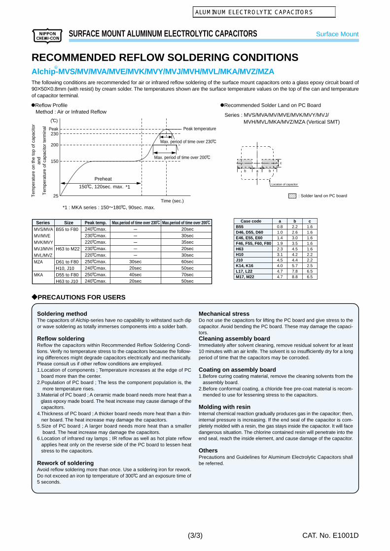
RECOMMENDED REFLOW SOLDERING CONDITIONSAlchip-MVS/MV/MVA/MVE/MVK/MVY/MVJ/MVH/MVL/MKA/MVZ/MZAThe following conditions are recommended for air or infrared reflow soldering of the surface mount capacitors onto a glass epoxy circuit board of90B50B0.8mm (with resist) by cream solder. The temperatures shown are the surface temperature values on the top of the can and temperatureof capacitor terminal.
Mechanical stressDo not use the capacitors for lifting the PC board and give stress to thecapacitor. Avoid bending the PC board. These may damage the capaci-tors.Cleaning assembly boardImmediately after solvent cleaning, remove residual solvent for at least10 minutes with an air knife. The solvent is so insufficiently dry for a longperiod of time that the capacitors may be corroded.
Coating on assembly board1.Before curing coating material, remove the cleaning solvents from the
assembly board.2.Before conformal coating, a chloride free pre-coat material is recom-
mended to use for lessening stress to the capacitors.
Molding with resinInternal chemical reaction gradually produces gas in the capacitor; then,internal pressure is increasing. If the end seal of the capacitor is com-pletely molded with a resin, the gas stays inside the capacitor. It will facedangerous situation. The chlorine contained resin will penetrate into theend seal, reach the inside element, and cause damage of the capacitor.
OthersPrecautions and Guidelines for Aluminum Electrolytic Capacitors shallbe referred.
Soldering methodThe capacitors of Alchip-series have no capability to withstand such dipor wave soldering as totally immerses components into a solder bath.
Reflow solderingReflow the capacitors within Recommended Reflow Soldering Condi-tions. Verify no temperature stress to the capacitors because the follow-ing differences might degrade capacitors electrically and mechanically.Please consult us if other reflow conditions are employed.1.Location of components ; Temperature increases at the edge of PC board more than the center.2.Population of PC board ; The less the component population is, the more temperature rises.3.Material of PC board ; A ceramic made board needs more heat than a glass epoxy made board. The heat increase may cause damage of the capacitors.4.Thickness of PC board ; A thicker board needs more heat than a thin-
ner board. The heat increase may damage the capacitors.5.Size of PC board ; A larger board needs more heat than a smaller board. The heat increase may damage the capacitors.6.Location of infrared ray lamps ; IR reflow as well as hot plate reflow applies heat only on the reverse side of the PC board to lessen heat stress to the capacitors.
Rework of solderingAvoid reflow soldering more than once. Use a soldering iron for rework.Do not exceed an iron tip temperature of 300C and an exposure time of5 seconds.
Series Max.period of time over 230c Max.period of time over 200cSize Peak temp.
Series : MVS/MVA/MV/MVE/MVK/MVY/MVJ/ MVH/MVL/MKA/MVZ/MZA (Vertical SMT)
(3/3)
STANDARDIZATION
CAT. No. E1001D
?LEAD TYPE REPLACEMENTS
?SNAP-IN REPLACEMENTS
?SCREW-MOUNT TERMINAL REPLACEMENTS
The following series are discontinued. Please use the recommended replacements in the table.
Discontinued series ReplacementsCharacteristicsSLSMSMCKMKMCSM-BPKM-BPSRSRCSRJSXSXASXCRXRXCLXESXFLXFTXFLX (10 to 63Vdc)KXKXCGXEULLLRKHAKXBBXSM (VP-type)SRFGX-VHSDKRLKSA
85C standard
105C standard
85C bi-polarized105C bi-polarized
85C low profile
Low impedance
Low impedanceLong life
Long life
High heat resistance
High temperature performance
Low leakage current
High ripple current
JIS B X-characteristices
85C large radial
High operating temperature2 volt105C low leakage currentBi-polarized high ripple
SMG
KME
SME-BPKME-BP
SRG
LXV
LXY
LXA
GXE
LXY
LLA
KMF / KMX
KMG
SMG / SMH
*
Discontinued series ReplacementsCharacteristicsSMSMESMGKMKMEKMGNMNMABKNM-HRBXLXLXARZ
85C standard
105C standard
Long case size
Long heightHigh ripple currentJIS B X-characteristics
Long life
Low impedance
SMH / SMM
KMH / KMM
SMH
KMH / KMM
LXG / LXQ
*
Discontinued series ReplacementsCharacteristicsEWPWMWGWSWRWRWAKMKMEFW
85C standard
100C
For inverter
High reliability
Low impedance
SME
KMH
RWE / RWF
KMH
KW
*Please consult us GX-VH, SD, KRL, KSA, and RZ series.
(1/1)
WORLD-WIDE MANUFACTURING LOCATIONS
CAT. No. E1001D
?AVAILABLE ITEMS BY MANUFACTURING LOCATIONS
KoreafactorySeriesClassification
Chinafactory
(Qingdao)
Chinafactory(Wuxi)
Taiwanfactory
Singaporefactory
Indonesiafactory
Malaysiafactory
U.S.A.factory
Low Profile
SMD
Generalpurpose
Bi-polar
Lowimpedance,Highripple
Snap-in
Screw-mountTerminal
MV
MVK
SRE
KRE
SRA
KMA
SRG
SMG
KMG
KME
SME-BP
KME-BP
KMF
LXV
KY
KZE
KMX
SMH
KMH
SMM
KMM
KMH
RWE
RWF
RWL
LXA
LX
Taiwan factory
U.S.A factory
Singapore factory
Malaysia factory
Indonesia factory
Nippon Chemi-Con
China factory (Wuxi)
China factory (Qingdao)
Korea factory
(1/1)
CONDUCTIVE POLYMER ALUMINUM SOLID CAPACITORS Surface Mount
CAT. No. E1001D
@Super low ESR, impedance and high heat resistance have been obtained by usingconductive polymer as electrolyte.(ESR and rated ripple current values are improved from PXA series.)@Rated voltage range : 2.5 to 16Vdc, Capacitance range : 27 to 470MF@Case size range : F5B6.0mm to F8B7.0mm@Suitable for DC-DC converters, voltage regulators and decoupling applications used to
computer motherboards etc.
?SPECIFICATIONS
(at 20C, 120Hz)(at 105C)
(at 20C after 2 minutes)
(at 20C, 120Hz)
(at 100kHz)
CategoryTemperature Range
Rated Voltage Range Capacitance ToleranceSurge Voltage Leakage Current
P20% (M)Rated voltageB1.15VI=0.2CV (max.)I : Max. leakage current (MA), C : Nominal capacitance (MF), V : Rated voltage (Vdc)
0.12 max.
Z(-25C)/Z(+20C)[1.15Z(-55C)/Z(+20C)[1.25
The following specifications shall be satisfied when the capacitors are restored to 20C after the rated voltage is applied for 1000 hours at 105C.Appearance No significant damageCapacitance change [P20% of the initial valueDF (tanE) [150% of the initial specified valueESR [150% of the initial specified valueLeakage current [The initial specified valueThe following specifications shall be satisfied when the capacitors are restored to 20C after subjecting them to the DC rated voltage at 60C, 90 to 95% RH for 500 hours.Appearance No significant damageCapacitance change [P20% of the initial valueDF (tanE) [150% of the initial specified valueESR [150% of the initial specified valueLeakage current [The initial specified valueThe capacitors shall be subjected to 1000 cycles each consisting of charge with the surge voltage specified at 105C for 30 secondsthrough a protective resistor(R=1kO) and discharge for 5 minutes 30 seconds.Appearance No significant damageCapacitance change [P20% of the initial valueDF (tanE) [150% of the initial specified valueESR [150% of the initial specified valueLeakage current [The initial specified value1% per 1000 hours maximum (Confidence level 60% at 105C)
Characteristics
?PART NUMBERING SYSTEM
?DIMENSIONS [mm]
FDP
0.5
LP0.3
0.3max. AP0.2
W
CP
0.2
BP
0.2
P Case codeE60F60H70
fD5
6.38
L5.75.76.7
A5.36.68.3
B5.36.68.3
C5.97.29.0
W0.5 to 0.80.5 to 0.80.7 to 1.1
P1.41.93.1
PXC 4 VC 220 M F60
Case codeCap tolerance (P20%)
Nominal cap codeTerminal type (VC)
Rated voltage in voltsSeries name
Capacitance39MF100MF220MF
Code39100220
?MARKING
C28M
2204V
EX) PXC4VC220M
*Note : If any doubt arises, measure the leakage current after following voltage treatment. Voltage treatment : DC rated voltage are applied to the capacitors for 120 minutes at 105C.
New!
(1/2)
CONDUCTIVE POLYMER ALUMINUM SOLID CAPACITORS Surface Mount
P20% (M)Rated voltageB1.15VShall not exceed values shown in STANDARD RATINGS.
0.12 max.
Z(-25C)/Z(+20C)[1.15Z(-55C)/Z(+20C)[1.25
The following specifications shall be satisfied when the capacitors are restored to 20C after the rated voltage is applied for 2000 hours at 105C.Appearance No significant damageCapacitance change [P20% of the initial valueDF (tanE) [150% of the initial specified valueESR [150% of the initial specified valueLeakage current [The initial specified valueThe following specifications shall be satisfied when the capacitors are restored to 20C after subjecting them to the DC rated voltage at 60C, 90 to 95% RH for 500 hours.Appearance No significant damageCapacitance change [P20% of the initial valueDF (tanE) [150% of the initial specified valueESR [150% of the initial specified valueLeakage current [The initial specified valueThe capacitors shall be subjected to 1000 cycles each consisting of charge with the surge voltage specified at 105C for 30 secondsthrough a protective resistor(R=1kO) and discharge for 5 minutes 30 seconds.Appearance No significant damageCapacitance change [P20% of the initial valueDF (tanE) [150% of the initial specified valueESR [150% of the initial specified valueLeakage current [The initial specified value1% per 1000 hours maximum (Confidence level 60% at 105C)
Characteristics
?PART NUMBERING SYSTEM
?DIMENSIONS (Terminal Type=VC) [mm]
PXA 16 VC 39 M F60
Case codeCap tolerance (P20%)
Nominal cap codeTerminal type (VC)
Rated voltage in voltsSeries name
Capacitance39MF100MF
1000MF
Code391001000
?MARKING
A905
3916V
EX) PXA16VC39M
*Note : If any doubt arises, measure the leakage current after following voltage treatment. Voltage treatment : DC rated voltage are applied to the capacitors for 120 minutes at 105C.
@Super low ESR, impedance and high heat resistance have been obtained by usingconductive polymer as electrolyte@Rated voltage range : 2.5 to 25Vdc, case size range : F6.3B5.5mm to F10B12.2mm
(Case code H12 and J12 newly added)@Suitable for DC-DC converters, voltage regulators and decoupling applications used to
computer motherboards etc.@High heat resistance to reflow soldering (See reflow soldering conditions)
Upgrade!
FDP
0.5
LP0.3 (Note)
0.3max. AP0.2
W
CP
0.2
BP
0.2
P
Note : LP0.5 for H12 and J12
Case codeF55F60H70J80H12J12
fD6.36.38
108
10
L5.25.76.77.7
12.012.2
A6.66.68.3
10.38.3
10.3
B6.66.68.3
10.38.3
10.3
C7.27.29.0
11.09.0
11.0
W0.5 to 0.80.5 to 0.80.7 to 1.10.7 to 1.10.7 to 1.10.7 to 1.1
P1.91.93.14.53.14.5
(1/2)
CONDUCTIVE POLYMER ALUMINUM SOLID CAPACITORS Surface Mount
CONDUCTIVE POLYMER ALUMINUM SOLID CAPACITORS Radial Lead
CAT. No. E1001D
@Super low ESR, high temperature resistance and high ripple current capability@Rated voltage range : 2.5 to 10Vdc
@2000 hours at 105C@Suitable for DC-DC converters, voltage regulators and decoupling applications
for computer motherboards
?SPECIFICATIONS
(at 20C, 120Hz)(at 105C)
(at 20C after 2 minutes)
(at 20C, 120Hz)
CategoryTemperature Range
Rated Voltage Range Capacitance ToleranceSurge Voltage Leakage Current *Note
Dissipation Factor(tane)
Low TemperatureCharacteristics
Endurance
Bias Humidity Test
Surge Voltage Test
Failure Rate
Items
-55 to +105C
2.5 to 10Vdc
P20% (M) Rated voltageB1.15VI=0.2CV (max.)Where, I : Leakage current (MA), C : Nominal capacitance (MF), V : Rated voltage (Vdc)
0.08 max.
Max. impedance ratio at 100kHz to the 20C valueZ(-25C)/Z(+20C)[1.15Z(-55C)/Z(+20C)[1.25The following specifications shall be satisfied when the capacitors are restored to 20C after the rated voltage is applied for 2000 hours at 105C.Appearance No significant damageCapacitance change [P20% of the initial measured valueD.F. (tanE) [150% of the initial specified valueESR [150% of the initial specified valueLeakage current [The initial specified valueThe following specifications shall be satisfied when the capacitors are restored to 20C after subjecting them to DC voltage at 60C, 90 to 95% RH for 1000 hours.Appearance No significant damageCapacitance change [P20% of the initial measured valueD.F. (tanE) [150% of the initial specified valueESR [150% of the initial specified valueLeakage current [The initial specified valueThe capacitors shall be subjected to 1000 cycles each consisting of charge with the surge voltage specified at 105C for 30 secondsthrough a protective resistor(R=1kO) and discharge for 5 minutes 30 seconds.Appearance No significant damageCapacitance change [P20% of the initial measured valueD.F. (tanE) [150% of the initial specified valueESR [150% of the initial specified valueLeakage current [The initial specified value1% per 1000 hours maximum (Confidence level 60% at 105C)
Characteristics
?DIMENSIONS [mm]?MARKING
*Note : If any doubt arises, measure the leakage current after the following voltage treatment. Voltage treatment : DC rated voltage is applied to the capacitors for 120 minutes at 105C.
fDLF
811.53.5
1011.55.0
Coated Case
L+1.5 max. 15min. 4min.
FD
+0.
5max
.
F0.
8
FP
0.5
A 292
5604V
EX) 4V560MF
New!
(1/2)
CONDUCTIVE POLYMER ALUMINUM SOLID CAPACITORS Radial Lead
CAT. No. E1001D
New!
?STANDARD RATINGS
?PART NUMBERING SYSTEMVB 5604PSA M H11 T15
Lead configuration codeCase code (H11 : 8B11.5, J12 : 10B11.5)
Design change codeCapacitance tolerance (P20%)
Nominal Capacitance codeTerminal type (VB)
Rated voltage in voltsSeries name
Capacitance270MF560MF820MF
Code270560820
Lead configuration codeT14: Ammo pack for F10(F=5.0)T15: Ammo pack for F8(F=3.5)E5 : Cut lead (Lead length C=3.5P0.5mm)
*Regarding to taping specifications and cut/formed lead, please consult us.
CONDUCTIVE POLYMER ALUMINUM SOLID CAPACITORS Radial Lead
CAT. No. E1001D
@Super low ESR, high temperature resistance@Large capacitance & Improved high ripple current capability@Rated voltage range : 2.5 to 25Vdc (20/25V newly added)@2000 hours at 105C@Suitable for DC-DC converters, voltage regulators and decoupling applications
For computer motherboards
?SPECIFICATIONS
(at 20C, 120Hz)(at 105C)
(at 20C after 2 minutes)
(at 20C, 120Hz)
CategoryTemperature Range
Rated Voltage Range Capacitance ToleranceSurge Voltage Leakage Current *Note
Dissipation Factor(tane)
Low TemperatureCharacteristics
Endurance
Bias Humidity Test
Surge Voltage Test
Failure Rate
Items
-55 to +105C
2.5 to 25Vdc
P20% (M) Rated voltageB1.15VI=0.2CV (max.)Where, I : Leakage current (MA), C : Nominal capacitance (MF), V : Rated voltage (Vdc)
0.12 max.
Max. impedance ratio at 100kHz to the 20C valueZ(-25C)/Z(+20C)[1.15Z(-55C)/Z(+20C)[1.25The following specifications shall be satisfied when the capacitors are restored to 20C after the rated voltage is applied for 2000 hours at 105C.Appearance No significant damageCapacitance change [P20% of the initial measured valueD.F. (tanE) [150% of the initial specified valueESR [150% of the initial specified valueLeakage current [The initial specified valueThe following specifications shall be satisfied when the capacitors are restored to 20C after subjecting them to DC voltage at 60C, 90 to 95% RH for 500 hours.Appearance No significant damageCapacitance change [P20% of the initial measured valueD.F. (tanE) [150% of the initial specified valueESR [150% of the initial specified valueLeakage current [The initial specified valueThe capacitors shall be subjected to 1000 cycles each consisting of charge with the surge voltage specified at 105C for 30 secondsthrough a protective resistor(R=1kO) and discharge for 5 minutes 30 seconds.Appearance No significant damageCapacitance change [P20% of the initial measured valueD.F. (tanE) [150% of the initial specified valueESR [150% of the initial specified valueLeakage current [The initial specified value1% per 1000 hours maximum (Confidence level 60% at 105C)
Characteristics
?DIMENSIONS [mm] ?MARKING
*Note : If any doubt arises, measure the leakage current after the following voltage treatment. Voltage treatment : DC rated voltage is applied to the capacitors for 120 minutes at 105C.
fDLF
811.53.5
1012.55.0
Coated Case
L+1.5 max. 15min. 4min.
FD
+0.
5max
.
F0.
6
FP
0.5
PS18M
8204V
EX) 4V820MF
Upgrade!
(1/2)
CONDUCTIVE POLYMER ALUMINUM SOLID CAPACITORS Radial Lead
CAT. No. E1001D
?STANDARD RATINGS
?PART NUMBERING SYSTEMPS 8204 M J12 -T14
Lead configuration codeCase code (H11 : 8B11.5, J12 : 10B12.5)
Design change numberCapacitance tolerance (P20%)
Nominal capacitance codeSeries name
Rated voltage code
Capacitance270MF560MF820MF
Code270560820
Rated voltage2.5V4V
6.3V10V16V20V25V
Code2R5
46
10162025
Lead configuration codeT14: Ammo pack for F10(F=5.0)T15: Ammo pack for F8(F=3.5)E5 : Cut lead (Lead length C=3.5P0.5mm)
*Regarding to taping specifications and cut/formed lead, please consult us.
P20% (M)I=0.01CV or 3MA, whichever is greater.Where, I : Max. leakage current (MA), C : Nominal capacitance (MF), V : Rated voltage (V)
See STANDARD RATINGS.
Rated voltage (Vdc)A6
Z(-25C)/Z(+20C) B6 & C6D6 to D13A6
Z(-40C)/Z(+20C) B6 & C6D6 to D13
The following specifications shall be satisfied when the capacitors are restored to 20C after the rated voltage is applied for 2000 hours at 85C.Case code A6 B6 & C6 D6 to D13Capacitance change [P30% of the initial value [P25% of the initial value [P20% of the initial valueD.F. (tanE) [200% of the initial specified value [200% of the initial specified value [200% of the initial specified valueLeakage current [The initial specified value [The initial specified value [The initial specified valueThe following specifications shall be satisfied when the capacitors are restored to 20C after exposing them for 500 hours at 85C without voltage applied.Capacitance change [P15% of the initial valueD.F. (tanE) [150% of the initial specified valueLeakage current [The initial specified value
P20% (M)I=0.01CV or 3MA, whichever is greater.Where, I : Max. leakage current (MA), C : Nominal capacitance (MF), V : Rated voltage (V)Rated voltage (Vdc)
B6 & C6tanE (Max.)
D6 to D13Rated voltage (Vdc)
Z(-25C)/Z(+20C)B6 & C6D6 to D13
Z(-40C)/Z(+20C)B6 & C6D6 to D13
The following specifications shall be satisfied when the capacitors are restored to 20C after the rated voltage is applied for 1000 hours at 105C.Case code B6 & C6 D6 to D13Capacitance change [P30% of the initial value [P20% of the initial valueD.F. (tanE) [200% of the initial specified value [200% of the initial specified valueLeakage current [The initial specified value [The initial specified valueThe following specifications shall be satisfied when the capacitors are restored to 20C after exposing them for 500 hours at 105C without voltage applied.Case code B6 & C6 D6 to D13Capacitance change [P25% of the initial value [P15% of the initial valueD.F. (tanE) [200% of the initial specified value [150% of the initial specified valueLeakage current [The initial specified value [The initial specified value
P20% (M)I=0.01CV or 3MA, whichever is greater.Where, I : Max. leakage current (MA), C : Nominal capacitance (MF), V : Rated voltage (V)Rated voltage (Vdc)tanE (Max.)Rated voltage (Vdc)Z(-25C)/Z(+20C)Z(-40C)/Z(+20C)The following specifications shall be satisfied when the capacitors are restored to 20C after the rated voltage is applied for 2000 hours at 105C.Capacitance change [P20% of the initial valueD.F. (tanE) [200% of the initial specified valueLeakage current The initial specified valueThe following specifications shall be satisfied when the capacitors are restored to 20C after exposing them for 500 hours at 105C without voltage applied.Capacitance change [P15% of the initial valueD.F. (tanE) [150% of the initial specified valueLeakage current [The initial specified value
Characteristics
10V0.30
16V0.25
10V38
16V26
25V0.22
25V24
35V0.18
35V23
50V0.18
50V23
Rated ripple current (mArms) at 105C, 100kHzMax. impedance (O) at 20C, 100kHzCase code
VdcmF 10 16 25 35 5047
100180220330470680
1,000
H15H20H25
0.400.270.20
330440570
H15H20H25
0.400.270.20
330440570
H15H20H25
0.400.270.20
330440570
H15H20H25
0.400.270.20
330440570
H15H15H20H25
0.400.400.270.20
330330440570
?DIMENSIONS (Terminal Type=FC) [mm]
?PART NUMBERING SYSTEM
H+
0.2m
ax.
PP0.3
W+0.1max.
0.2max.
L+0.5max.
2P0.51.5
C
1.5
Marking
Case codeH15H20H25
L 17.121.526.5
W9.09.09.0
H9.09.09.0
P7.47.47.4
C05
10
MFK 10 FC 1000 M H25
Case code
Cap tolerance (P20%)Nominal cap in MFTerminal type (FC)
Rated voltage in voltsSeries name
?MARKINGEX) 35V330MF
9 J3
30
35
V+ -
(1/1)
SURFACE MOUNT ALUMINUM ELECTROLYTIC CAPACITORS 4.5mm height, 85C
CAT. No. E1001D
@4.5mm height@Endurance : 85C 2000 hours@Reflow capability@Solvent-proof type (see PRECAUTIONS AND GUIDELINES)
?SPECIFICATIONS
?STANDARD RATINGS
(at 20C, 120Hz)
(at 20C after 2 minutes)
(at 20C, 120Hz)
(at 120Hz)
CategoryTemperature Range
Rated Voltage RangeCapacitance ToleranceLeakage Current
P20% (M)I=0.01CV or 3MA, whichever is greater.Where, I : Max. leakage current (MA), C : Nominal capacitance (MF), V : Rated voltage (V)Rated voltage (Vdc)tanE (Max.)Rated voltage (Vdc)Z(-25C)/Z(+20C)Z(-40C)/Z(+20C)The following specifications shall be satisfied when the capacitors are restored to 20C after the rated voltage is applied for 2000 hours at 85C.Rated voltage 4 & 6.3Vdc 10 to 50Vdc
Capacitance change [P30% of the initial value [P25% of the initial valueDF (tanE) [300% of the initial specified value [300% of the initial specified valueLeakage current [The initial specified value [The initial specified valueThe following specifications shall be satisfied when the capacitors are restored to 20C after exposing them for 1000 hours at 85C without voltage applied.Rated voltage 4 & 6.3Vdc 10 to 50Vdc
Capacitance change [P30% of the initial value [P25% of the initial valueDF (tanE) [300% of the initial specified value [300% of the initial specified valueLeakage current [The initial specified value [The initial specified value
Case codeRated ripple current (mArms) at 85C, 120Hz
Note : Use next higher voltage part.
downsized
MVS
MV
?DIMENSIONS (Terminal Type=VC) [mm]
Case codeD46E46F46
D45
6.3
A4.35.36.6
B4.35.36.6
C5.15.97.2
W0.5 to 0.80.5 to 0.80.5 to 0.8
P1.01.41.9
FDP
0.5
4.5
0.3max. AP0.2
W
CP
0.2
BP
0.2
P
+0.1-0.2
MVS 16 VC 47 M F46Capacitance
0.1MF0.47MF1.0MF4.7MF10MF
100MF
CodeR1
R471
4R710
100
Case code
Cap tolerance (P20%)Nominal cap code
Terminal type (VC)Rated voltage in volts
Series name
?PART NUMBERING SYSTEM
?MARKING
7hS
4716V
EX) 16V47MF
(1/1)
SURFACE MOUNT ALUMINUM ELECTROLYTIC CAPACITORS Downsized, 85C
CAT. No. E1001D
@F4 through F18 case sizes are fully lined up@Endurance : 85C 2000 hours@Suitable to fit for downsized equipment@Solvent-proof type except 100 to 450Vdc (see PRECAUTIONS AND GUIDELINES)
downsizedsize extended
MVA
MV
?SPECIFICATIONS
(at 20C, 120Hz)
(at 20C)
(at 20C, 120Hz)
(at 120Hz)
CategoryTemperature Range
Rated Voltage RangeCapacitance ToleranceLeakage Current
The following specifications shall be satisfied when the capacitors are restored to 20C after the rated voltage is applied for 2000 hours at 85C.Case codeRated voltage (Vdc) Capacitance change [P30% of the initial value [P20% of the initial valueDF (tanE) [200% of the initial specified value [200% of the initial specified valueLeakage current [The initial specified value [The initial specified valueThe following specifications shall be satisfied when the capacitors are restored to 20C after exposing them for 1000 hours at 85Cwithout voltage applied.Case codeRated voltage Capacitance change [P30% of the initial value [P20% of the initial valueDF (tanE) [200% of the initial specified value [200% of the initial specified valueLeakage current [The initial specified value [The initial specified value
Characteristics
4V0.42-
4V717--
6.3V0.350.38
6.3V410512
10V0.300.34
10V38410
16V0.260.30
16V2638
25V0.160.26
25V2425
35V0.140.22
35V2324
50V0.120.18
50V2323
63V0.120.14
63V2323
100V0.120.10
100V3423
160 to 250V-
0.20
160 to 250V--36
400 & 450V-
0.25
400 & 450V--610
D55 to J10K14 to M22
D55 to J10
K14 to M22
I=0.01CV or 3MA, whichever is greater.(after 2 minutes)I=0.03CV or 4MA, whichever is greater.(after 1 minute)
D55 to J10K14 to M22
4 to 100V 160 to 450V-
I=0.04CV+100MA max.(after 1 minute)
D55 to J104V & 6.3V
D55 to J1010 to 100V
K14 to M226.3 to 450V
D55 to J104V & 6.3V
D55 to J1010 to 100V
K14 to M226.3 to 450V
MVA 16 VC 47 M E55
Tray code (TR : If necessary)Case code
Cap tolerance (P20%)Nominal cap code
Terminal type (VC or VE)Rated voltage in volts
Series name
Capacitance0.1MF1.0MF4.7MF10MF
100MF1000MF
CodeR11
4R7101001000
?PART NUMBERING SYSTEM
?DIMENSIONS (Terminal Type=VC or VE) [mm]
Case codeD55E55F55F60F80H10J10K14K16L17L22M17M22
D45
6.36.36.3810
12.512.516161818
L5.25.25.25.77.710.010.013.516.016.521.516.521.5
A4.35.36.66.66.68.310.313.013.017.017.019.019.0
B4.35.36.66.66.68.310.313.013.017.017.019.019.0
C5.15.97.27.27.29.011.013.713.718.018.020.020.0
W 0.5 to 0.80.5 to 0.80.5 to 0.80.5 to 0.80.5 to 0.80.7 to 1.10.7 to 1.11.0 to 1.31.0 to 1.31.0 to 1.31.0 to 1.31.0 to 1.31.0 to 1.3
P1.01.41.91.91.93.14.54.24.26.56.56.56.5
FDP
0.5
LP0.3(Note)
0.3max. AP0.2
W
CP
0.2
BP
0.2
P
Note : LP0.5 for H10, J10, K14 and K16
D55 to K16 (VC)
L17 to M22 (VE : with dummy terminals)
FDP
0.5
BP
0.2
LP0.5
0.3max.
AP0.2
W
CP
0.2
P
: Dummy terminals
?MARKING
7hA
4716V
EX) 16V47MF
MVA0V
100025V
EX) 25V1000MF
D55 to J10
K14 to H22
(1/2)
SURFACE MOUNT ALUMINUM ELECTROLYTIC CAPACITORS Downsized, 85C
CAT. No. E1001D
?STANDARD RATINGS4 6.3 10 5016 25 35VdcmF
Rated ripple current (mArms) at 85C, 120HzCase code
Rated ripple current (mArms) at 85C, 120HzCase code
3.34.71022334756
100150220330
470
680820
1,000
1,500
2,200
3,300
4,700
6,800
10,000
D55D55
E55
F55F80
F80
H10
2530
50
80135
150
320
D55D55
E55
F55F80
H10
H10H10
J10
J10
K14
K16L17
L17
L22M17M22
3033
55
88135
280
290320
430
480
890
10001200
1400
175017002000
D55D55E55
F55F55F80H10
H10
J10
K14
L17
L22M17
M22
263044
7079
130270
280
430
960
1300
15501600
1850
D55E55E55
F55F80F80H10
H10
J10
K14
L17
L22M17
M22
263744
70110130270
280
380
710
1150
14501450
1750
2441476066
120210260300
400
820
14501400
1800
D55E55E55F55F55F80H10H10H10
J10
K14
L22M17
M22
D55D55E55F55F80F80
H10
J10K14K16L17
L22M22
D55D55E55F55F60
F80H10H10J10
K14
L17
M22
1824415464
120210260360
600
1100
1700
151830477085
190
320600740850
13001400
63 100 160 200 250 400 450VdcmF0.100.220.330.47
1.02.23.34.710
22
33
47
56
68
100
220
330
470
D55D55D55D55D55D55E55E55F55
F80
H10
H10
J10
J10
K14
K14
K16L17L17M17
1.33458
12172032
60
110
130
160
170
380
580
720820950
1000
H10
J10
K14
K14
L22M17
M22
90
120
380
440
850800
1000
K16
L17
L22M17
370
500
590590
K14
K16
L17
L22M17
M22
240
310
420
510510
590
150
240
340420420
490
K14
K16
L17L22M17
M22
K14L17
L22
M22
K14L17L22M17M22
120140280280350
120140
280
350
Non solvent-proof
(2/2)
SURFACE MOUNT ALUMINUM ELECTROLYTIC CAPACITORS Standard, 85C
CAT. No. E1001D
@From 5.5mm height@Suitable to fit for downsized equipment@Solvent-proof type (see PRECAUTIONS AND GUIDELINES)
?SPECIFICATIONS
?STANDARD RATINGS
?DIMENSIONS (Terminal Type=VC) [mm]
downsized
low profile
105C
MV MVK
MVA
MVS
(at 20C, 120Hz)
(at 20C after 2 minutes)
(at 20C,120Hz)
(at 120Hz)
CategoryTemperature Range
Rated Voltage Range Capacitance ToleranceLeakage Current
P20% (M)I=0.01CV or 3MA, whichever is greater.Where, I : Max. leakage current (MA), C : Nominal capacitance (MF), V : Rated voltage (V)Rated voltage (Vdc)
B55tanE (Max.) D55 to F60
H63 to J10Rated voltage (Vdc)Z(-25C)/Z(+20C)
B55Z(-40C)/Z(+20C) D55 to F60
H63 to J10The following specifications shall be satisfied when the capacitors are restored to 20C after the rated voltage is applied for 2000 hours (B55 size 1000 hours) at 85C.Capacitance change [P20% of the initial valueD.F. (tanE) [200% of the initial specified valueLeakage current [The initial specified valueThe following specifications shall be satisfied when the capacitors are restored to 20C after exposing them for 500 hours at 85C without voltage applied.Case code B55 D55 to J10Capacitance change [P20% of the initial value [P15% of the initial valueD.F. (tanE) [200% of the initial specified value [150% of the initial specified valueLeakage current [The initial specified value [The initial specified value
W0.45 to 0.750.5 to 0.80.5 to 0.80.5 to 0.80.5 to 0.80.7 to 1.10.7 to 1.1
P0.81.01.41.92.33.14.5
* : L=5.7 for D60, E60 and F60.Note : LP0.5 for H63, H10 and J10
FDP
0.5
LP0.3 (Note)0.3max. AP0.2
W
CP
0.2
BP
0.2
P
MV 50 VC R1 M D55Capacitance
0.1MF0.47MF1.0MF4.7MF10MF100MF
1000MF
CodeR1R47
14R7101001000
Case codeCap tolerance (P20%)
Nominal cap codeTerminal type (VC)
Rated voltage in voltsSeries name
?PART NUMBERING SYSTEM
?MARKING
7h
1006.3V
EX)6.3V100MF
10h16
EX)16V10MFB55 D55 to J10
Note : Use next higher voltage part.
(1/1)
SURFACE MOUNT ALUMINUM ELECTROLYTIC CAPACITORS Downsized, 105C
CAT. No. E1001D
@Rated voltage range : 6.3 to 450V, capacitance range : 0.47 to 6800MF@Endurance : 1000 to 2000 hours at 105C@Case size range : F4B5.5 to F18B21.5@Solvent-proof type except 100 to 450Vdc (see PRECAUTIONS AND GUIDELINES)
?SPECIFICATIONS
?DIMENSIONS (Terminal Type=VC or VE) [mm]
(20C, 120Hz)
(20C)
(20C, 120Hz)
(120Hz)
[P20% of the initial value[200% of the initial specified value[The initial specified value
2000 hours[P20% of the initial value[200% of the initial specified value[The initial specified value
-40 to +105C
6.3 to 450Vdc
P20%(M)Rated voltage(Vdc)D55 to J10 I=0.01CV or 3MA, whichever is greater (2 minutes)K14 to M22 I=0.03CV or 4MA, whichever is greater (1 minute) I=0.04CV+100MA (1minute)Where, I : Max. leakage current (MA), C : Nominal capacitance (MF), V : Rated voltage (V)See STANDARD RATINGS
Rated voltage (Vdc) Z(-25C)/Z(+20C) Z(-40C)/Z(+20C) Z(-25C)/Z(+20C) Z(-40C)/Z(+20C)
The following specifications shall be satisfied when the capacitors are restored to 20C after the rated voltage is applied for the specifiedperiod of time at 105C.Case codeTime 1000 hoursCapacitance change [P30% of the initial valueD.F. (tanE) [300% of the initial specified valueLeakage current [The initial specified valueThe following specifications shall be satisfied when the capacitors are restored to 20C after exposing them for 1000 hours (500 hoursfor B55 to F80 size) at 105C without voltage applied.Case codeCapacitance change [P25% of the initial valueD.F. (tanE) [200% of the initial specified valueLeakage current [The initial specified value
6.3V412510
10V3848
16V2636
25V2424
35V2323
50V2323
63V2323
160 to 250V--36
400 to 450V--610
100V3423
6.3 to 100V 160 to 450V-
D55 to J10
K14 to M22
D55 to F80 H10 to M22
D55 to F80 H10 to H22
CategoryTemperature Range
Rated Voltage Range Capacitance ToleranceLeakage Current
P20% (M)I=0.01CV or 3MA, whichever is greater.Where, I : Max. leakage current (MA), C : Nominal capacitance (MF), V : Rated voltage (V)Rated voltage (Vdc)
D55 to F55tanE (Max.)
H63 to J10Rated voltage (Vdc)Z(-25C)/Z(+20C)Z(-40C)/Z(+20C)The following specifications shall be satisfied when the capacitors are restored to 20C after the rated voltage is applied for the specifiedperiod of time at 105C.Case code D55 to F55 H63 to J10Time 1000hours 2000hoursCapacitance change [P30% of the initial value [P20% of the initial valueD.F. (tanE) [300% of the initial specified value [200% of the initial specified valueLeakage current [The initial specified value [The initial specified valueThe following specifications shall be satisfied when the capacitors are restored to 20C after exposing them for the specified time at 105C without voltage applied.Case code D55 to F55 H63 to J10Time 500hours 1000hoursCapacitance change [P25% of the initial value [P20% of the initial valueD.F. (tanE) [200% of the initial specified value [200% of the initial specified valueLeakage current [The initial specified value [The initial specified value
Characteristics
6.3V0.300.406.3V
410
10V0.240.3010V
38
16V0.200.2616V
26
25V0.160.1625V
24
35V0.140.1435V
23
50V0.120.1250V
23
(at 20C, 120Hz)
(at 20C after 2 minutes)
(at 20C,120Hz)
(at 120Hz)
Case code
Rated ripple current (mArms) at 105C, 120Hz
0.1 0.220.330.471.02.23.34.7
10223347
1002203304701000
6.3 10 16 25 35 50mF Vdc
1.32.63.23.85.6
1014192970
140170310
D55D55D55D55D55D55D55E55F55H63H10H10J10
15254080
375
D55E55F55H63
J10
4580
180
450
F55H63H10
J10
1630
48
460
D55E55
F55
J10
21
3656
290
410
D55
E55F55
H10
J10
34
90180
E55
H63H10
Case codeD55E55F55H63H10J10
D45
6.38810
L5.25.25.26.310.010.0
A4.35.36.68.38.310.3
B4.35.36.68.38.310.3
C5.15.97.29.09.011.0
W0.5 to 0.80.5 to 0.80.5 to 0.80.5 to 0.80.7 to 1.10.7 to 1.1
P1.01.41.92.33.14.5
MVK 50 VC R47 M D55Capacitance
0.1MF0.47MF1.0MF4.7MF10MF
100MF1000MF
CodeR1
R471
4R710
1001000
Case codeCap tolerance (P20%)
Nominal cap codeTerminal type (VC)
Rated voltage in voltsSeries name
?PART NUMBERING SYSTEM
Note : LP0.5 for H63, H10 and J10
FDP
0.5
LP0.3 (Note)0.3max. AP0.2
W
CP
0.2
BP
0.2
P
Note : Use next higher voltage part.
?MARKING
7hK
1006.3V
EX) 6.3V100MF
(1/1)
SURFACE MOUNT ALUMINUM ELECTROLYTIC CAPACITORS Pb Free, 105C
CAT. No. E1001D
@Endurance at 105C 1000 to 2000 hours assured@Rated voltage : 6.3V to 50V, Nominal capacitance : 0.1 to 1000MF@Case sizes : F4B5.5 to F10B10.5mm@Solvent-proof type (see PRECAUTIONS AND GUIDELINES)
P20%(M)I=0.01CV or 3MA, whichever is greaterWhere, I : Max. leakage current (MA), C : Nominal capacitance (MF), V : Rated voltage (V)Rated voltage(Vdc)
tanE(Max.) D55 to F55
F80 to J10Rated voltage(Vdc)Z(-25C)/Z(+20C)Z(-40C)/Z(+20C)The following specifications shall be satisfied when the capacitors are restored to 20C after the rated voltage is applied for the specifiedperiod of time at 105C.Sizes D55 to F55Time 1000 hoursCapacitance change [P30% of the initial measured valueD.F. (tanE) [300% of the initial specified valueLeakage current [The initial specified value
Characteristics
6.3V0.300.406.3410
10V0.240.301038
16V0.200.261626
25V0.160.162524
35V0.140.143523
50V0.120.125023
F80,H63,H10,J102000 hours[P20% of the initial measured value[200% of the initial specified value[The initial specified value
?PART NUMBERING SYSTEM
?DIMENSIONS (Terminal Type = VC) [mm]
?STANDARD RATINGS6.3 10 16 25 35 50VdcmF
Case codeRated ripple current (mArms) at 105C, 120Hz
0.1 0.220.330.471.0 2.2 3.3 4.7 10
22
33
47
100
220 330 470
1,000
D55
E55
F55
H10
J10
21
36
56
290
410
E55
F80(H63)H10
34
9090
180
D55
E55
F55
J10
16
30
48
460
F55
F80(H63)
H10
J10
45
8080
180
450
1525
40
8080
375
D55E55
F55
F80(H63)
J10
D55D55D55D55D55D55D55E55F55F80
(H63)
H10
H10
J10
1.32.63.23.85.6
10 14 19 29 70 70
140
170
310
?MARKING
FDP
0.5
LP0.3 (Note)0.3max. AP0.2
W
CP
0.2
BP
0.2
P
Note : LP0.5 for H63, H10 and J10
Case codeD55E55F55F80H63H10J10
D45
6.36.38810
L5.25.25.27.76.310.010.0
A4.35.36.66.68.38.310.3
B4.35.36.66.68.38.310.3
C5.15.97.27.29.09.011.0
W0.5 to 0.80.5 to 0.80.5 to 0.80.5 to 0.80.5 to 0.80.7 to 1.10.7 to 1.1
P1.01.41.91.92.33.14.5
1R100CKA
EX) 16V100MF
MKA 35 VC 220 M J10Capacitance
0.1MF0.47MF1.0MF4.7MF10MF
100MF1000MF
CodeR1R47
14R7101001000
Case codeCapacitance tolerance (P20%)
Nominal capacitance codeTerminal type (VC)
Rated voltage in voltsSeries name
Note : Parenthesized capacitances are sub-standard parts.
Note : Use next higher voltage part.
Pb Free
MKA
MVK
?RATED VOLTAGE CODERated voltage (Vdc)
6.31016253550
CodejACEVH
(1/1)
SURFACE MOUNT ALUMINUM ELECTROLYTIC CAPACITORS Lower impedance, 105C
CAT. No. E1001D
@Very low impedance, 105C 2000 hour-life@Pb-free design : Sn-Bi plating terminal@Solvent-proof type (see PRECAUTIONS AND GUIDELINES)
?SPECIFICATIONS
(20C, 120Hz)
(at 20C after 2 minutes)
(20C, 120Hz)
(120Hz)
CategoryTemperature Range
Rated Voltage RangeCapacitance ToleranceLeakage Current
P20%(M)I=0.01CV or 3MA, whichever is greaterWhere, I : Max. leakage current (MA), C : Nominal capacitance (MF), V : Rated voltage (V)Rated voltage(Vdc)tanE (Max.)Rated voltage(Vdc)Z(-25C)/Z(+20C)Z(-40C)/Z(+20C)Z(-55C)/Z(+20C)The following specifications shall be satisfied when the capacitors are restored to 20C after the rated voltage is applied for 2000 hoursat 105C.Capacitance change [P30% of the initial measured valueD.F. (tanE) [200% of the initial specified valueLeakage current [The initial specified value
Characteristics
6.3V0.266.3V
234
10V0.1910V
234
16V0.1616V
234
25V0.1425V
233
35V0.1235V
233
50V0.1050V
233
?PART NUMBERING SYSTEM
?DIMENSIONS [mm]
?STANDARD RATINGS
Rated ripple current (mArms) at 105C, 100kHzImpedance (O max.) at 20C, 100kHzCase code
6.3 10 16 25 35 504.7
10
22
33
47
100
220 330 470 680
1000 1500
D61
D61E61E61F61F61F80H10
H10J10
1.35
1.350.700.700.360.360.340.16
0.160.08
90
90160160240240280600
600850
D61
D61E61
F80H10H10H10J10
1.35
1.350.70
0.340.160.160.160.08
90
90160
280600600600850
D61
D61E61
E61F61F61
F80H10H10J10
1.35
1.350.70
0.700.360.36
0.340.160.160.08
90
90160
160240240
280600600850
D61
E61
E61F61F61
F80
H10H10J10
1.35
0.70
0.700.360.36
0.34
0.160.160.08
90
160
160240240
280
600600850
D61D61E61E61
F61
F61
F80H10H10J10
1.351.350.700.70
0.36
0.36
0.340.160.160.08
9090
160160
240
240
280600600850
D61E61F61F61
F80
F80
H10
J10
2.901.520.880.88
0.68
0.68
0.34
0.18
6085
165165
195
195
350
670
VdcmF
?MARKING
FDP
0.5
LP0.3 (Note)0.3max. AP0.2
W
CP
0.2
BP
0.2
P
Note : LP0.5 for H10 and J10
Case codeD61E61F61F80H10J10
D45
6.36.3810
L5.85.85.87.710.010.0
A4.35.36.66.68.310.3
B4.35.36.66.68.310.3
C5.15.97.27.29.011.0
W0.5 to 0.80.5 to 0.80.5 to 0.80.5 to 0.80.7 to 1.10.7 to 1.1
P1.01.41.91.93.14.5
2j
220CZA
EX) 16V220MF
MZA 16 VC 220 M F80
Capacitance4.7MF10MF
100MF1000MF
Code4R7101001000
Case codeCapacitance tolerance (P20%)
Nominal capacitance codeTerminal type (VC)
Rated voltage in voltsSeries name
?RATED VOLTAGE CODE Rated voltage (Vdc)
6.310 16 25 35 50
CodejACEVH
New!
lower Z
MZA
MVZ
lower Z
MVY
Note : Use next higher voltage part.
(1/1)
SURFACE MOUNT ALUMINUM ELECTROLYTIC CAPACITORS Low impedance, 105C
CAT. No. E1001D
@Very low impedance, 105C 1000-2000 hour-life@Solvent-proof type (see PRECAUTIONS AND GUIDELINES)
?SPECIFICATIONS
(20C, 120Hz)
(at 20C after 2 minutes)
(20C, 120Hz)
(120Hz)
10 to 25V[P25% of the initial value[200% of the initial specified value[The initial specified value
CategoryTemperature Range
Rated Voltage RangeCapacitance ToleranceLeakage Current
P20%(M)I=0.01CV or 3MA, whichever is greaterWhere, I : Max. leakage current (MA), C : Nominal capacitance (MF), V : Rated voltage (V)Rated voltage(Vdc)
D60 to F80tanE (Max.)
H10, J10Rated voltage(Vdc)Z(-25C)/Z(+20C)Z(-55C)/Z(+20C)The following specifications shall be satisfied when the capacitors are restored to 20C after the rated voltage is applied for 1000 hours(H10/J10 sizes 2,000 hours) at 105C.Rated voltage (Vdc) 6.3VCapacitance change [P30% of the initial valueD.F. (tanE) [200% of the initial specified valueLeakage current [The initial specified value
Characteristics
6.3V0.240.286.3V
35
10V0.200.2410V
24
16V0.160.2016V
24
25V0.140.1625V
23
?PART NUMBERING SYSTEM
?DIMENSIONS [mm]
?STANDARD RATINGS6.3 10 16 25VdcmF
Case codeImpedance (O) at 20C, 100kHzRated ripple current (mArms) at 105C, 100kHz
W0.5 to 0.80.5 to 0.80.5 to 0.80.5 to 0.80.7 to 1.10.7 to 1.1
P1.01.41.91.93.14.5
0VZ
22016V
EX) 16V220MF
MVZ 16 VC 220 M F80
Capacitance4.7MF10MF100MF1000MF
Code4R7101001000
Case codeCapacitance tolerance (P20%)
Nominal capacitance codeTerminal type (VC)
Rated voltage in voltsSeries name
Note : Use next higher voltage part.
Lower Z
Lower Z
MVZ
MVY
MZA
(1/1)
SURFACE MOUNT ALUMINUM ELECTROLYTIC CAPACITORS Low impedance, 105C
CAT. No. E1001D
@Expand up to F18 case size@Expand up to 100Vdc
@Low impedance, 105C 1000 to 5000-hours-life@For digital equipment, especially DC-DC converters and VRM@Solvent-proof type except 80 & 100Vdc (see PRECAUTIONS AND GUIDELINES)
lower Zsize extended
MVYlower Z
MVK
MVZlower Z
MZA
?SPECIFICATIONS
(at 20C, 120Hz)
(at 20C after 2 minutes)
(at 20C, 120Hz)
(at 120Hz)
D55 to F80 : 1000 hoursH10 & J10 : 2000 hoursK14 to M22 : 5000 hours
CategoryTemperature Range
Rated Voltage Range Capacitance ToleranceLeakage Current
-55 to +105C (6.3 to 63Vdc) -40 to +105C (80 & 100Vdc)
6.3 to 100Vdc
P20% (M)I=0.01CV or 3MA, whichever is greater.Where, I : Max. leakage current (MA), C : Nominal capacitance (MF), V : Rated voltage (V)Rated voltage (Vdc)
tanE (Max.)
Rated voltage (Vdc)
Z(-40C)/Z(+20C)
The following specifications shall be satisfied when the capacitors are restored to 20C after the rated voltage is applied for specified time at 105C.Time
Rated voltage 6.3Vdc (D55 to J10) 6.3 to 100Vdc Capacitance change [P30% of the initial value [P20% of the initial valueD.F. (tanE) [300% of the initial specified value [200% of the initial specified valueLeakage current [The initial specified value [The initial specified valueThe following specifications shall be satisfied when the capacitors are restored to 20C after exposing them for 1000 hours at 105C withoutvoltage applied.Rated voltage 6.3Vdc (D55 to J10) 6.3 to 100Vdc
Capacitance change [P30% of the initial value [P20% of the initial valueD.F. (tanE) [300% of the initial specified value [200% of the initial specified valueLeakage current [The initial specified value [The initial specified value
Characteristics
6.3V0.240.280.266.3V
310
10V0.200.240.2210V
28
16V0.160.200.1816V
26
25V0.140.160.1625V
24
35V0.120.140.1435V
23
50V0.120.120.1250V
23
63V--
0.1463V-3
80V--
0.1080V-3
100V--
0.10100V-3
D55 to F80H10 & J10K14 to M22
D55 to J10K14 to M22
When nominal capacitance exceeds1000MF, add 0.02 to the value abovefor each 1000MF increase.
MVY 50 VC 220 M J10
Capacitance1.0MF4.7MF10MF
100MF1000MF
Code1
4R7101001000
Tray code (TR : If necessary)Case code
Cap tolerance (P20%)Nominal cap code
Terminal type (VC or VE)Rated voltage in volts
Series name
?PART NUMBERING SYSTEM
?DIMENSIONS (Terminal Type=VC or VE) [mm]
FDP
0.5
LP0.3 (Note)0.3max. AP0.2
W
CP
0.2
BP
0.2
P
Note : LP0.5 for H10, J10, K14 and K16
D55 to K16 (VC)
L17 to M22 (VE : with dummy terminals)
FDP
0.5
BP
0.2
LP0.5
0.3max.
AP0.2
W
CP
0.2
P
: Dummy terminals
Case codeD55E55F55F80H10J10K14K16L17L22M17M22
FD45
6.36.3810
12.512.516161818
L5.25.25.27.710.010.013.516.016.521.516.521.5
A4.35.36.66.68.310.313.013.017.017.019.019.0
B4.35.36.66.68.310.313.013.017.017.019.019.0
C5.15.97.27.29.011.013.713.718.018.020.020.0
W0.5 to 0.80.5 to 0.80.5 to 0.80.5 to 0.80.7 to 1.10.7 to 1.11.0 to 1.31.0 to 1.31.0 to 1.31.0 to 1.31.0 to 1.31.0 to 1.3
P1.01.41.91.93.14.54.24.26.56.56.56.5
?MARKING
7hY
1006.3V
EX) 6.3V100MF
K14 to M22
D55 to J10
MVY0V
100016V
EX) 16V1000MF
(1/2)
SURFACE MOUNT ALUMINUM ELECTROLYTIC CAPACITORS Low impedance, 105C
CAT. No. E1001D
?STANDARD RATINGS
Rated ripple current (mArms) at 105C, 100kHzImpedance (O) at 20C, 100kHzCase code
Case codeImpedance (O) at 20C, 100kHzRated ripple current (mArms) at 105C, 100kHz
6.3 10 16 25 35VdcmF4.7
1022334768
100220
330
470
680
1,000
1,500
2,200
3,300
4,700
6,800
8,200
D55E55E55
F55F55
F80
H10
H10
H10
J10K14L17K16M17L22M17L22M22M22
3.01.81.8
1.01.0
0.34
0.30
0.30
0.30
0.150.0700.0540.0600.0540.0380.0540.0380.0380.038
609595
140140
280
450
450
450
670820
1,260950
1,3501,6301,3501,6301,7501,750
E55E55F55
F55F80
H10
H10
J10
J10
K16L17L17M17L22M22
M22
1.81.81.0
1.00.34
0.30
0.30
0.15
0.15
0.0600.0540.0540.0540.0380.038
0.038
9595
140
140280
450
450
670
670
9501,2601,2601,3501,6301,750
1,750
D55E55F55F55
F55F80
H10
H10
J10K14L17
L17M17L22M17
M22
3.01.81.01.0
1.00.34
0.30
0.30
0.150.0700.054
0.0540.0540.0380.054
0.038
6095
140140
140280
450
450
670820
1,260
1,2601,3501,6301,350
1,750
E55F55F55F55
F80H10
H10
J10
L17M17
L22M22
M22
1.81.01.01.0
0.340.30
0.30
0.15
0.0540.054
0.0380.038
0.038
95140140140
280450
450
670
1,2601,350
1,6301,750
1,750
D55E55F55F55F55F80H10H10
J10
K14L17
L17M17
M22
3.01.81.01.01.00.340.300.30
0.15
0.0700.054
0.0540.054
0.038
6095
140140140280450450
670
8201,260
1,2601,350
1,750
50 63 80 100VdcmF1.02.23.34.7
1022334768
100
220
330
470
1,000
D55D55D55E55F55F55F80F80H10
H10
J10
K14L17L17M17M22
5.05.05.03.02.02.00.600.600.60
0.60
0.30
0.110.0870.0870.0870.050
303030507070
170170300
300
500
650900900
1,0601,520
K14
K14
K14L17L17M17L22M17
0.19
0.19
0.190.120.120.120.0850.12
500
500
500845845905
1,100905
K14
K16
L22M17
M22
0.33
0.26
0.160.24
0.16
450
550
900700
950
K14K14K14L17L22M17
M22
0.330.330.330.240.160.24
0.16
450450450650900700
950
Non solvent-proof
(2/2)
SURFACE MOUNT ALUMINUM ELECTROLYTIC CAPACITORS Long life, 105C
CAT. No. E1001D
@Endurance : 105C 2000 hours@Solvent-proof type (see PRECAUTIONS AND GUIDELINES)
?SPECIFICATIONS
?STANDARD RATINGS
(at 20C, 120Hz)
(at 20C after 2 minutes)
(at 20C, 120Hz)
(at 120Hz)
CategoryTemperature Range
Rated Voltage Range Capacitance ToleranceLeakage Current
P20% (M)I=0.01CV or 3MA, whichever is greater.Where, I : Max. leakage current (MA), C : Nominal capacitance (MF), V : Rated voltage (V)Rated voltage (Vdc)tanE (Max.)Rated voltage (Vdc)Z(-25C)/Z(+20C)Z(-40C)/Z(+20C)The following specifications shall be satisfied when the capacitors are restored to 20C after the rated voltage is applied for 2000 hours at 105C.Rated voltage 6.3Vdc 10 & 16Vdc 25 to 50Vdc
Capacitance change [P30% of the initial value [P25% of the initial value [P20% of the initial valueD.F. (tanE) [300% of the initial specified value [300% of the initial specified value [200% of the initial specified valueLeakage current The initial specified value [The initial specified value [The initial specified valueThe following specifications shall be satisfied when the capacitors are restored to 20C after exposing them for 1000 hours at 105C without voltage applied.Rated voltage 6.3Vdc 10 & 16Vdc 25 to 50Vdc
Capacitance change [P30% of the initial value [P25% of the initial value [P20% of the initial valueD.F. (tanE) [300% of the initial specified value [300% of the initial specified value [200% of the initial specified valueLeakage current [The initial specified value [The initial specified value [The initial specified value
Characteristics
6.3V0.306.3V
412
10V0.2410V
38
16V0.2016V
26
25V0.1625V
24
35V0.1435V
23
50V0.1250V
23
0.10.220.330.47
1.02.23.34.7
10 22 33 47 100
D60D60D60D60D60D60D60E60F60
152540
D60E60F60
45F60
1630
48
D60E60
F60
34E6021
3656
D60
E60F60
mF Vdc 6.3 10 16 25 35 50
Case code
Rated ripple current (mArms) at 105C, 120Hz
1.3 2.6 3.2 3.8 5.6
10141929
longer life
MVJ
MVK
?DIMENSIONS (Terminal Type=VC) [mm]
?PART NUMBERING SYSTEM
FDP
0.5
LP0.30.3max. AP0.2
W
CP
0.2
BP
0.2
P
Case codeD60E60F60
D45
6.3
A4.35.36.6
L5.75.75.7
B4.35.36.6
C5.15.97.2
W0.5 to 0.80.5 to 0.80.5 to 0.8
P1.01.41.9
MVJ 16 VC 22 M E60
Capacitance0.1MF1.0MF4.7MF10MF
100MF
CodeR11
4R710
100
Case code
Cap tolerance (P20%)Nominal cap code
Terminal type (VC)Rated voltage in volts
Series name
Note : Use next higher voltage part.
?MARKING
7hJ
1006.3V
EX) 6.3V100MF
(1/1)
SURFACE MOUNT ALUMINUM ELECTROLYTIC CAPACITORS 3000 to 5000-hours-life, 105C
CAT. No. E1001D
@Endurance : 105C 3000 to 5000 hours (F80 to J10 added)@Suitable for applications requiring long life such as continuously operating
equipment, industrial applications, etc@Solvent-proof type (see PRECAUTIONS AND GUIDELINES)
?SPECIFICATIONS
(at 20C,120Hz)
(at 20C, after 2 minutes)
(at 20C,120Hz)
(120Hz)
CategoryTemperature Range
Rated Voltage RangeCapacitance ToleranceLeakage Current
P20%(M)I=0.03CV or 4MA, whichever is greaterWhere, I : Max. leakage current (MA), C : Nominal capacitance (MF), V : Rated voltage (V)Rated voltage (Vdc)Max. tanERated voltage(Vdc)Z(-25C)/Z(+20C)Z(-40C)/Z(+20C)After the capacitors are subjected to the rated DC voltage for 3000 hours (H10 & J10 sizes 5000 hours) at 105C, the followingspecifications shall be satisfied when the capacitors are restored to 20C.Capacitance change [P30% of the initial measured valueD.F. (tanE) [300% of the initial specified valueLeakage current [The initial specified valueThe following specifications shall be satisfied when the capacitors are restored to 20C after exposing them for 1000 hours at 105Cwithout voltage applied. Capacitance change [P30% of the initial measured valueD.F. (tanE) [300% of the initial specified valueLeakage current [The initial specified value
Characteristics
6.3V0.286.3V
410
10V0.2410V
37
16V0.2016V
25
25V0.1625V
23
35V0.1335V
23
50V0.1250V
23
?PART NUMBERING SYSTEM
?DIMENSIONS (Terminal Type=VC) [mm]
?STANDARD RATINGS6.3 10 16 25 35 50VdcmF
0.1 0.220.330.471.0 2.2 3.3 4.7
10 22 33 47
100 220 330 470
1,000
D60
E60F60F80H10
J10
22
3660
101160
313
E60
H10
35
141
D60E60
F60F80
J10
1830
5081
254
F60F80H10
J10
4863
116
238
15254257
216
D60E60F60F80
J10
D60D60D60D60D60D60D60E60F60F80H10H10J10
1.02.63.23.86.2
11 14 19 30 49 77 92
151
Case codeRated ripple current (mArms) at 105C, 120Hz
?MARKING
FDP
0.5
LP0.3 (Note)0.3max. AP0.2
W
CP
0.2
BP
0.2
P
Note : LP0.5 for H63 to J10
Case codeD60E60F60F80H63H10J10
D45
6.36.38810
L5.75.75.77.76.310.010.0
A4.35.36.66.68.38.310.3
B4.35.36.66.68.38.310.3
C5.15.97.27.29.09.011.0
W0.5 to 0.80.5 to 0.80.5 to 0.80.5 to 0.80.5 to 0.80.7 to 1.10.7 to 1.1
P1.01.41.91.92.33.14.5
Outer dimensions9hL
4716V
EX) 16V47MF
MVL 35 VC 10 M E60
Capacitance0.1MF2.2MF10MF100MF
CodeR12R210100
Case codeCapacitance tolerance (P20%)
Nominal capacitance codeTerminal type (VC)
Rated voltage in voltsSeries name
Note : Use a next higher voltage part.
Longer life
MVL
MVJ
(1/1)
SURFACE MOUNT ALUMINUM ELECTROLYTIC CAPACITORS High heat resistance, 125C
CAT. No. E1001D
@Endurance : 125C 1000 to 5000 hours@Suitable to fit for automotive equipment@Solvent-proof type (10 to 50V) (see PRECAUTIONS AND GUIDELINES)
?SPECIFICATIONS
CategoryTemperature Range
Rated Voltage Range Capacitance ToleranceLeakage Current
I=0.03CV or 4MA, whichever is greater. Where, I : Max. leakage current (MA), C : Nominal capacitance (MF), V : Rated voltage (V)Rated voltage (Vdc)
tanE (Max.)
When nominal capacitance exceeds 1000MF, add 0.02 to the value above for each 1000MF increase.Rated voltage (Vdc) Z(-25C)/Z(+20C) Z(-40C)/Z(+20C) Z(-25C)/Z(+20C) Z(-40C)/Z(+20C)The following specifications shall be satisfied when the capacitors are restored to 20C after the rated voltage is applied for the specified time at 125C.
F60 to H63 (10 to 100Vdc) : 1000hours
Time H10 to J10 (10 to 100Vdc) : 2000hours
K14 to M22 (10 to 100Vdc) : 5000hours K14 to M22 (160 to 450Vdc) : 2000hours
Capacitance change [P30% of the initial valueD.F. (tanE) [300% of the initial specified valueLeakage current [The initial specified valueThe following specifications shall be satisfied when the capacitors are restored to 20C after exposing them for 1000 hours (500 hours for 350 to 450WV) at 125C without voltage applied.Rated voltage(Vdc) 10 to 50Vdc 63 to 450Vdc
Capacitance change [P30% of the initial value [P30% of the initial valueD.F. (tanE) [300% of the initial specified value [300% of the initial specified valueLeakage current [The initial specified value [500% of the initial specified value
Characteristics
10V0.240.22
10V41048
16V0.200.18
16V3836
25V0.160.16
25V2624
35V0.140.14
35V2423
50V0.140.12
50V2423
63V0.180.14
63V2423
100V0.180.10
100V2423
160 to 250V-
0.20
160 to 250V--36
400 & 450V-
0.24
400 & 450V--610
(at 20C, 120Hz)
(at 20C after 2 minutes)
(at 20C, 120Hz)
(at 120Hz)
F60 to J10K14 to M22
F60 to J10
K14 to M22
160 to 450Vdc
I=0.04CV+100 (160 to 450Vdc)
125Csize extended
MVH
MVK
?DIMENSIONS (Terminal Type=VC or VE) [mm]
?PART NUMBERING SYSTEM
FDP
0.5
LP0.5 (Note)0.3max. AP0.2
W
CP
0.2
BP
0.2
P
Note : LP0.3 for F60 and F80
F60 to K16 (VC)
L17 to M22 (VE : with dummy terminals)
FDP
0.5
BP
0.2
LP0.5
0.3max.
AP0.2
W
CP
0.2
P
: Dummy terminals
MVH 35 VC 47 M H10
Capacitance10MF
100MF1000MF
Code101001000
Tray code (TR : If necessary)Case code
Cap tolerance (P20%)Nominal cap code
Terminal type (VC or VE)Rated voltage in volts
Series name
Case codeF60F80H63H10J10K14K16L17L22M17M22
D6.36.388
1012.512.516161818
L5.77.76.310.010.013.516.016.521.516.521.5
A6.66.68.38.310.313.013.017.017.019.019.0
B6.66.68.38.310.313.013.017.017.019.019.0
C7.27.29.09.011.013.713.718.018.020.020.0
W0.5 to 0.80.5 to 0.80.5 to 0.80.7 to 1.10.7 to 1.11.0 to 1.31.0 to 1.31.0 to 1.31.0 to 1.31.0 to 1.31.0 to 1.3
P1.91.92.33.14.54.24.26.56.56.56.5
?MARKING
74H
4735V
EX) 35V47MF
MVH0V
100016V
EX) 16V1000MF
K14 to M22
F60 to J10
(1/2)
SURFACE MOUNT ALUMINUM ELECTROLYTIC CAPACITORS High heat resistance, 125C
CAT. No. E1001D
?STANDARD RATINGS
10
22
33
47
100
220
330
470
680
1,000
2,200
3,3004,700
H63F80H10
J10
K14L17M17M17M22
46.046.020.0
13.4
2.11.51.51.5
0.87
2.32.31.0
0.7
0.140.100.100.10
0.058
7272
136
188
7501,0001,2001,2001,550
F60
H63F80
H10
J10
K14
K14L17L17M17M22
66.0
46.046.0
20.0
13.4
2.1
2.1 1.5 1.5 1.5 0.87
3.3
2.32.3
1.0
0.7
0.14
0.140.100.100.100.058
45
6868
126
211
750
7501,0001,0001,2001,550
F60
F60
H63F80
H10
J10
K14L17K16L17
M17
66.0
66.0
46.046.0
20.0
13.4
2.11.51.51.5
1.5
3.3
3.3
2.32.3
1.0
0.7
0.140.100.110.10
0.10
27
39
6262
92
151
7501,000
9001,000
1,200
F60
H63F80H10J10
K14K14L17K16L17M17
66.0
46.046.020.013.4
3.53.52.32.72.32.3
3.3
2.32.31.00.7
0.230.230.150.180.150.15
38
505083
111
550550850700850920
F60
K14
K14L17M17
M17
66.0
2.1
2.11.51.5
1.5
3.3
0.14
0.140.100.10
0.10
43
750
7501,0001,200
1,200
10
20c -40c
Case Code
ESR(omax/100kHz)
Rated ripplecurrent
(mArms/ 125c, 100kHz) 20c -40c
Case Code
ESR(omax/100kHz)
Rated ripplecurrent
(mArms/ 125c, 100kHz) 20c -40c
Case Code
ESR(omax/100kHz)
Rated ripplecurrent
(mArms/ 125c, 100kHz) 20c -40c
Case Code
ESR(omax/100kHz)
Rated ripplecurrent
(mArms/ 125c, 100kHz)
16 25 35
mF
Items
Vdc
10
22
334768
100
220
330
470
H63F80
H10
J10
K14
K16
L17
L22
115 115
50.0
35.0
12.5
10.0
9.0
5.5
2.32.3
1.0
0.7
0.25
0.20
0.18
0.11
4242
56
71
500
600
820
1,100
H10
J10
K14K16L17
M22
50
35
16.513.012.0
8.0
1.0
0.70
0.330.260.24
0.16
53
63
450550650
950
50 63 100
20c -40c
Case Code
ESR(omax/100kHz)
Rated ripplecurrent
(mArms/ 125c, 100kHz) 20c -40c
Case Code
ESR(omax/100kHz)
Rated ripplecurrent
(mArms/ 125c, 100kHz) 20c -40c
Case Code
ESR(omax/100kHz)
Rated ripplecurrent
(mArms/ 125c, 100kHz)mF
Items
Vdc
Case CodeRated ripple current(mArms/ 125c, 120Hz)
Case CodeRated ripple current(mArms/ 125c, 120Hz)
Case CodeRated ripple current(mArms/ 125c, 120Hz)
Case CodeRated ripple current(mArms/ 125c, 120Hz)
Case CodeRated ripple current(mArms/ 125c, 120Hz)mF
Items
Vdc
3.34.76.8
10
22
33
4768
K14
L17
M17
M22
100
180
245
380
K16
L22M17
M22
110
205200
260
K14L17L22M17
70100140135
K16L17
M22
6585
145K14
L17
L22M17M22
100
180
250245315
160 200 250 400 450
Non-solvent proof
Non-solvent proof
(2/2)
SURFACE MOUNT ALUMINUM ELECTROLYTIC CAPACITORS Bi-polarized 85C
CAT. No. E1001D
@Bi-polarized chip type for the circuit, of which polarity is frequently reversed@Solvent-proof type (see PRECAUTIONS AND GUIDELINES)
?SPECIFICATIONS
(at 20C, 120Hz)
(at 20C after 2 minutes)
(at 20C, 120Hz)
(at 120Hz)
CategoryTemperature Range
Rated Voltage Range Capacitance ToleranceLeakage Current
P20% (M)I=0.05CV or 10MA, whichever is greater.Where, I : Max. leakage current (MA), C : Nominal capacitance (MF), V : Rated voltage (V)Rated voltage (Vdc)tanE (Max.)Rated voltage (Vdc)Z(-25C)/Z(+20C)Z(-40C)/Z(+20C)The following specifications shall be satisfied when the capacitors are restored to 20C after the rated voltage is applied for 2000 hours at 85C, however the polarization shall be reversed every 250 hours.Capacitance change [P20% of the initial valueD.F. (tanE) [200% of the initial specified valueLeakage current [The initial specified valueThe following specifications shall be satisfied when the capacitors are restored to 20C after exposing them for 500 hours at 85C without voltage applied.Capacitance change [P15% of the initial valueD.F. (tanE) [150% of the initial specified valueLeakage current [The initial specified value
Characteristics
4V0.45
4V715
6.3V0.32
6.3V410
10V0.26
10V38
16V0.24
16V26
25V0.22
25V24
35V0.20
35V23
50V0.20
50V23
MV 50 VC R47 M BP
Capacitance0.1MF0.47MF1.0MF4.7MF10MF
CodeR1
R471
4R710
D55
Case code
Bi-polar typeCap tolerance (P20%)
Nominal cap codeTerminal type (VC)
Rated voltage in voltsSeries name
?PART NUMBERING SYSTEM
?STANDARD RATINGS
1.31.92.32.83.44.15.56.5
9 11 14
D55D55D55D55D55D55D55D55E55E55F55
8
131721
9
15
24
D55
E55F55F55
D55
E55
F55
11
18
28
D55
E55
F55
12
21
33
D55
E55
F55
13
23
36
D55
E55
F55
14D55
0.10.150.220.330.470.68
1.01.52.23.34.76.8
10 15 22 33 47
4 6.3 10 16 25 35 50mF Vdc
Case code
Rated ripple current (mArms) at 85C, 120Hz
?DIMENSIONS (Terminal Type=VC) [mm]
Case codeD55E55F55
D45
6.3
A4.35.36.6
L5.25.25.2
B4.35.36.6
C5.15.97.2
W0.5 to 0.80.5 to 0.80.5 to 0.8
P1.01.41.9
FDP
0.5
LP0.3
0.3max. AP0.2
W
CP
0.2
BP
0.2
P
bi-polarized
MV-BP
MV
?MARKING
94
4.735V
EX) 35V4.7MF
Note : Use next higher voltage part.
(1/1)
SURFACE MOUNT ALUMINUM ELECTROLYTIC CAPACITORS Bi-polarized, 105C
CAT. No. E1001D
@Bi-polarized chip type for the circuit, of which polarity is frequently reversed@Solvent-proof type (see PRECAUTIONS AND GUIDELINES)
?SPECIFICATIONS
(at 20C, 120Hz)
(at 20C after 2 minutes)
(at 20C, 120Hz)
(at 120Hz)
CategoryTemperature Range
Rated Voltage Range Capacitance ToleranceLeakage Current
P20% (M)I=0.05CV or 10MA, whichever is greater.Where, I : Max. leakage current (MA), C : Nominal capacitance (MF), V : Rated voltage (V)Rated voltage (Vdc)tanE (Max.)Rated voltage (Vdc)Z(-25C)/Z(+20C)Z(-40C)/Z(+20C)The following specifications shall be satisfied when the capacitors are restored to 20C after the rated voltage is applied for 1000 hours at 105C, however the polarization shall be reversed every 250 hours.Capacitance change [P30% of the initial valueD.F. (tanE) [300% of the initial specified valueLeakage current [The initial specified valueThe following specifications shall be satisfied when the capacitors are restored to 20C after exposing them for 500 hours at 105C without voltage applied.Capacitance change [P25% of the initial valueD.F. (tanE) [200% of the initial specified valueLeakage current [The initial specified value
@Coating case covered products are also available@Downsized from current standard SRE series@5mm height, 1000-hours-life at 85C@Solvent-proof type (see PRECAUTIONS AND GUIDELINES)
?SPECIFICATIONS
?STANDARD RATINGS
(at 20C, 120Hz)
(at 20C after 2 minutes)
(at 20C, 120Hz)
(at 120Hz)
CategoryTemperature Range
Rated Voltage Range Capacitance ToleranceLeakage Current
P20% (M)I=0.01CV or 3MA, whichever is greater.Where, I : Max. leakage current (MA), C : Nominal capacitance (MF), V : Rated voltage (V)Rated voltage (Vdc)tanE (Max.)Rated voltage (Vdc)Z(-25C)/Z(+20C)Z(-40C)/Z(+20C)The following specifications shall be satisfied when the capacitors are restored to 20C after the rated voltage is applied for 1000 hours at 85C.Capacitance change [P20% of the initial valueD.F. (tanE) [200% of the initial specified valueLeakage current [The initial specified valueThe following specifications shall be satisfied when the capacitors are restored to 20C after exposing them for 1000 hours at 85C without voltage applied.Capacitance change [P20% of the initial valueD.F. (tanE) [200% of the initial specified valueLeakage current [The initial specified value
P20% (M)I=0.01CV or 3MA, whichever is greater.Where, I : Max. leakage current (MA), C : Nominal capacitance (MF), V : Rated voltage (V)Rated voltage (Vdc)tanE (Max.)Rated voltage (Vdc)Z(-25C)/Z(+20C)Z(-40C)/Z(+20C)The following specifications shall be satisfied when the capacitors are restored to 20C after the rated voltage is applied for 1000 hours at 85C.Capacitance change [P20% of the initial valueD.F. (tanE) [200% of the initial specified valueLeakage current [The initial specified valueThe following specifications shall be satisfied when the capacitors are restored to 20C after exposing them for 1000 hours at 85C without voltage applied.Capacitance change [P20% of the initial valueD.F. (tanE) [200% of the initial specified valueLeakage current [The initial specified value
Characteristics
4V0.354V715
6.3V0.246.3V
410
10V0.2010V
38
16V0.1616V
26
25V0.1425V
24
35V0.1235V
23
50V0.1050V
23
4 6.3 10 16 25 35 50 0.1
0.15 0.22 0.33 0.47 0.68
1.0 1.5 2.2 3.3 4.7 6.8
101522334768
100
VdcmF
4B5 23
3B5 3.5B5
4B5
5B5
6.3B5
121723
38
60
3B5
4B5
5B5
6.3B5
11
20
35
54
3B5 3.5B5 3.5B5
5B5 5B5
6.3B5
1014172632
50
3B5 3.5B5
4B5
6.3B5
9.31216
45
3B5 3.5B5
4B5 5B5 5B5
6.3B5 6.3B5
8.3111520253340
3B53B53B53B53B53B53B53B5
3.5B54B55B5
6.3B56.3B5
1.32.02.93.54.25.16.27.5
10 14 19 24 29
Case size FDBL (mm)
Rated ripple current (mArms) at 85C, 120Hz
?DIMENSIONS (Radial Lead Type=VB) [mm]
?PART NUMBERING SYSTEM
Sleeve
L' 15min. 4min.
FD
'
Fd
FP
0.3
FP
0.5
(F3 & F3.5) (F4 to F6.3)Gas escape end seal
30.41.0
fDfdFfD'L'
3.50.41.0
40.451.5
FD+0.5max.L+1.0max.
50.452.0
6.30.452.5
SRE 6.3 VB 100 MCapacitance
0.1MF0.47MF1.0MF4.7MF10MF100MF
CodeR1
R471
4R710
100
Cap tolerance (P20%)Nominal cap code
Radial lead typeRated voltage in volts
Series name
downsized
SRE
SRM
Note1 : Use next higher voltage part.Note2 : The parts of F3.5B5 will be unified to F4B5.
P20% (M)I=0.01CV or 3MA, whichever is greater.Where, I : Max. leakage current (MA), C : Nominal capacitance (MF), V : Rated voltage (V)Rated voltage (Vdc)tanE (Max.)Add 0.02 for F3 products.Rated voltage (Vdc)Z(-25C)/Z(+20C)Z(-40C)/Z(+20C)The following specifications shall be satisfied when the capacitors are restored to 20C after the rated voltage is applied for 1000 hours at 105C.FD F3 & F3.5 F4 to F6.3Capacitance change [P25% of the initial value [P20% of the initial valueD.F. (tanE) [200% of the initial specified value [200% of the initial specified valueLeakage current [The initial specified value [The initial specified valueThe following specifications shall be satisfied when the capacitors are restored to 20C after exposing them for 500 hours at 105C without voltage applied.FD F3 & F3.5 F4 to F6.3Capacitance change [P25% of the initial value [P20% of the initial valueD.F. (tanE) [200% of the initial specified value [200% of the initial specified valueLeakage current [The initial specified value [The initial specified value
Characteristics
6.3V0.27
6.3V39
10V0.23
10V37
16V0.19
16V25
25V0.15
25V23
35V0.13
35V23
50V0.11
50V23
(at 20C, 120Hz)
(at 20C after 2 minutes)
(at 20C, 120Hz)
(at 120Hz)
VdcmF 0.1
0.15 0.22 0.33 0.47 0.68
1.0 1.5 2.2 3.3 4.7 6.8
10 15 22 33 47 68100
10 16 25 35 50 1.3 2.0 2.6 3.2 3.8 4.6 5.6
6.9 1014192429
3B5 3B5 3B5 3B5 3B5 3B5 3B5 3B5
3.5B5 4B5 5B5
6.3B5 6.3B5
7.7111520253340
3B5 3.5B5
4B5 5B5 5B5
6.3B5 6.3B5
8.81216
45
9.413162530
48
3B5 3.5B5
4B5
6.3B5
3B5 3.5B5 3.5B5
5B5 5B5
6.3B5
11
20
34
52
3B5
4B5
5B5
6.3B5
121621
36
56
3B5 3.5B5
4B5
5B5
6.3B5
Case size FDBL (mm)
Rated ripple current (mArms) at 105C, 120Hz
6.3
?DIMENSIONS (Radial Lead Type=VB) [mm]
?PART NUMBERING SYSTEM
Sleeve
L' 15min. 4min.
FD
'
Fd
FP
0.3
FP
0.5
30.41.0
fDfdFfD'L'
3.50.41.0
40.451.5
FD+0.5max.L+1.0max.
50.452.0
6.30.452.5
KRE 16 VB 47 MCapacitance
0.1MF0.47MF1.0MF4.7MF10MF100MF
CodeR1
R471
4R710
100
Cap tolerance (P20%)Nominal cap code
Radial lead typeRated voltage in volts
Series name
105C
KRE
SRE
Note1 : Use next higher voltage part.Note2 : The parts of F3.5B5 will be unified to F4B5.
P20% (M)I=0.01CV or 3MA, whichever is greater.Where, I : Max. leakage current (MA), C : Nominal capacitance (MF), V : Rated voltage (V)Rated voltage (Vdc)tanE (Max.)Rated voltage (Vdc)Z(-25C)/Z(+20C)Z(-40C)/Z(+20C)The following specifications shall be satisfied when the capacitors are restored to 20C after the rated voltage is applied for 1000 hours at 85C.Capacitance change [P20% of the initial valueD.F. (tanE) [200% of the initial specified valueLeakage current [The initial specified valueThe following specifications shall be satisfied when the capacitors are restored to 20C after exposing them for 500 hours at 85C without voltage applied.Capacitance change [P20% of the initial valueD.F. (tanE) [200% of the initial specified valueLeakage current [The initial specified value
P20% (M)I=0.01CV or 3MA, whichever is greater.Where, I : Max. leakage current (MA), C : Nominal capacitance (MF), V : Rated voltage (V)Rated voltage (Vdc)tanE (Max.)Rated voltage (Vdc)Z(-25C)/Z(+20C)Z(-40C)/Z(+20C)The following specifications shall be satisfied when the capacitors are restored to 20C after the rated voltage is applied for 1000 hours at 105C.Rated voltage 4 to 16Vdc 25 to 63Vdc
Capacitance change [P25% of the initial value [P20% of the initial valueD.F. (tanE) [200% of the initial specified valueLeakage current [The initial specified valueThe following specifications shall be satisfied when the capacitors are restored to 20C after exposing them for 1000 hours at 105C without voltage applied.Rated voltage 4 to 16Vdc 25 to 63Vdc
Capacitance change [P25% of the initial value [P20% of the initial valueD.F. (tanE) [200% of the initial specified valueLeakage current [The initial specified value
P20% (M)I=0.01CV or 3MA, whichever is greater.Where, I : Max. leakage current (MA), C : Nominal capacitance (MF), V : Rated voltage (V)Rated voltage (Vdc)tanE (Max.)When nominal capacitance exceeds 1000MF, add 0.03 to the value above for each 1000MF increase.Rated voltage (Vdc)Z(-25C)/Z(+20C)Z(-40C)/Z(+20C)The following specifications shall be satisfied when the capacitors are restored to 20C after the rated voltage is applied for 2000 hours (1000 hours for F8 and smaller) at 85C.Capacitance change [P20% of the initial valueD.F. (tanE) [200% of the initial specified valueLeakage current [The initial specified valueThe following specifications shall be satisfied when the capacitors are restored to 20C after exposing them for 1000 hours at 85C without voltage applied.Capacitance change [P20% of the initial valueD.F. (tanE) [200% of the initial specified valueLeakage current [The initial specified value
P20% (M)I=0.01CV or 3MA, whichever is greater.Where, I : Max. leakage current (MA), C : Nominal capacitance (MF), V : Rated voltage (V)Rated voltage (Vdc)tanE (Max.)When nominal capacitance exceeds 1000MF, add 0.03 to the value above for each 1000MF increase.Rated voltage (Vdc)Z(-25C)/Z(+20C)Z(-40C)/Z(+20C)The following specifications shall be satisfied when the capacitors are restored to 20C after the rated voltage is applied for 1000 hours at 105C.Rated voltage 6.3 to 16Vdc 25 to 50Vdc
Capacitance change [P25% of the initial value [P20% of the initial valueD.F. (tanE) [200% of the initial specified value [200% of the initial specified valueLeakage current [The initial specified value [The initial specified valueThe following specifications shall be satisfied when the capacitors are restored to 20C after exposing them for 500 hours at 105C without voltage applied.Rated voltage 6.3 to 16Vdc 25 to 50Vdc
Capacitance change [P25% of the initial value [P20% of the initial valueD.F. (tanE) [200% of the initial specified value [200% of the initial specified valueLeakage current [The initial specified value [The initial specified value
[F18 I=0.03CV or 4MA, whichever is greater. After 1minute CV[1000 I=0.1CV+40 max. CV>1000 I=0.04CV+100 max.
]F20 I=0.03CVWhere, I : Max. leakage current (MA), C : Nominal capacitance (MF), V : Rated voltage (V)Rated voltage (Vdc)tanE (Max.)When nominal capacitance exceeds 1000MF, add 0.02 to the value above for each 1000MF increase.Rated voltage (Vdc)Z(-25C)/Z(+20C) [F8
]F10Z(-40C)/Z(+20C) [F8
]F10The following specifications shall be satisfied when the capacitors are restored to 20C after the rated voltage is applied for 2000 hours at 85C.Capacitance change [P20% of the initial valueD.F. (tanE) [200% of the initial specified valueLeakage current [The initial specified valueThe following specifications shall be satisfied when the capacitors are restored to 20C after exposing them for 1000 hours at 85C without voltage applied.Rated voltage 6.3 to 100Vdc 160 to 450Vdc
Capacitance change [P20% of the initial value [P20% of the initial valueD.F. (tanE) [200% of the initial specified value [200% of the initial specified valueLeakage current [The initial specified value [500% of the initial specified value
-55 to +105C(6.3 to 100Vdc) -40 to +105C(160 to 400Vdc) -25 to +105C(450Vdc)
6.3 to 450Vdc
P20% (M) 6.3 to 100Vdc 160 to 450Vdc
I=0.03CV or 4MA, whichever is greater. After 1minuteCV[1000 I=0.1CV+40 max.CV>1000 I=0.04CV+100 max.
I=0.03CV max.Where, I : Max. leakage current (MA), C : Nominal capacitance (MF), V : Rated voltage (V)Rated voltage (Vdc)tanE (Max.)When nominal capacitance exceeds 1000MF, add 0.02 to the value above for each 1000MF increase.Rated voltage (Vdc)
Z(-25C)/Z(+20C)
Z(-40C)/Z(+20C)
The following specifications shall be satisfied when the capacitors are restored to 20C after subjected to DC voltage with the ratedripple current is applied for 1000 hours (2000 hours for F10 and more at 105C).Capacitance change [P20% of the initial valueD.F. (tanE) [200% of the initial specified valueLeakage current [The initial specified valueThe following specifications shall be satisfied when the capacitors are restored to 20C after exposing them for 1000 hours at 105C without voltage applied.Rated voltage 6.3 to 100Vdc 160 to 450Vdc
Capacitance change [P20% of the initial value [P20% of the initial valueD.F. (tanE) [200% of the initial specified value [200% of the initial specified valueLeakage current [The initial specified value [500% of the initial specified value
Characteristics
6.3V0.28
10V0.24
16V0.20
25V0.16
35V0.14
50V0.12
63V0.10
100V0.08
450V0.24
160 to 250V0.20
350 to 400V0.24
6.3V551010
10V4488
16V3366
25V2244
35V2233
50V2233
63 to 100V2233
450V66--
350V4486
400V4486
250V33104
160 to 200V3384
TimeCV
[F8]F10[F8]F10
[F18
]F20
?PART NUMBERING SYSTEMKMQ 6.3 VB 1000 M Capacitance
[F18 I=0.03CV or 4MA, whichever is greater. After 1minute After 5minutes CV[1000 I=0.1CV+40 I=0.03CV+15 CV>1000 I=0.04CV+100 I=0.02CV+25
]F20 I=0.03CVWhere, I : Max. leakage current (MA), C : Nominal capacitance (MF), V : Rated voltage (V)Rated voltage (Vdc)
tanE (Max.)[F18]F20
When nominal capacitance exceeds 1000MF, add 0.02 to the value above for each 1000MF increase.Rated voltage (Vdc)Z(-25C)/Z(+20C) [F18
]F20Z(-40C)/Z(+20C) [F18The following specifications shall be satisfied when the capacitors are restored to 20C after the rated voltage is applied for 2000 hours at 85C.Capacitance change [P20% of the initial valueD.F. (tanE) [200% of the initial specified valueLeakage current [The initial specified valueThe following specifications shall be satisfied when the capacitors are restored to 20C after exposing them for 1000 hours at 85C without voltage applied.Rated voltage 6.3 to 100Vdc 160 to 450Vdc
Capacitance change [P20% of the initial value [P20% of the initial valueD.F. (tanE) [200% of the initial specified value [200% of the initial specified valueLeakage current [The initial specified value [500% of the initial specified value
-55 to +105C(6.3 to 100Vdc) -40 to +105C(160 to 400Vdc) -25 to +105C(450Vdc)
6.3 to 450Vdc
P20% (M)6.3 to 100Vdc 160 to 450Vdc
I=0.03CV or 4MA, whichever is greater. After 1minute After 5minutesCV[1000 I=0.1CV+40 I=0.03CV+15CV>1000 I=0.04CV+100 I=0.02CV+25
Where, I : Max. leakage current (MA), C : Nominal capacitance (MF), V : Rated voltage (V)Rated voltage (Vdc)tanE (Max.)When nominal capacitance exceeds 1000MF, add 0.02 to the value above for each 1000MF increase.Rated voltage (Vdc)Z(-25C)/Z(+20C)Z(-40C)/Z(+20C)The following specifications shall be satisfied when the capacitors are restored to 20C after subjected to DC voltage with the ratedripple current is applied for 1000 hours (2000 hours to meet the following two conditions 1) : 160Vdc and larger, 2) : F12.5 and larger) at 105C.Capacitance change [P20% of the initial valueD.F. (tanE) [200% of the initial specified valueLeakage current [The initial specified valueThe following specifications shall be satisfied when the capacitors are restored to 20C after exposing them for 1000 hours at 105C without voltage applied.Rated voltage 6.3 to 100Vdc 160 to 450Vdc
Capacitance change [P20% of the initial value [P20% of the initial valueD.F. (tanE) [200% of the initial specified value [200% of the initial specified valueLeakage current [The initial specified value [500% of the initial specified value
-55 to +105C(6.3 to 100Vdc) -40 to +105C(160 to 400Vdc)
6.3 to 400Vdc
P20% (M)6.3 to 100Vdc 160 to 400Vdc
I=0.03CV or 4MA, whichever is greater. After 1minute After 5minutesI=0.01CV or 3MA, whichever is greater. CV[1000 I=0.1CV+40 I=0.03CV+15
CV>1000 I=0.04CV+100 I=0.02CV+25
Where, I : Max. leakage current (MA), C : Nominal capacitance (MF), V : Rated voltage (V)Rated voltage (Vdc)tanE (Max.)When nominal capacitance exceeds 1000MF, add 0.02 to the value above for each 1000MF increase.Rated voltage (Vdc)Z(-25C)/Z(+20C)Z(-40C)/Z(+20C)The following specifications shall be satisfied when the capacitors are restored to 20C after subjected to DC voltage with the rated ripplecurrent is applied for 1000 hours at 105C.Capacitance change [P20% of the initial valueD.F. (tanE) [200% of the initial specified valueLeakage current [The initial specified valueThe following specifications shall be satisfied when the capacitors are restored to 20C after exposing them for 1000 hours at 105C without voltage applied.Rated voltage 6.3 to 100Vdc 160 to 400Vdc
Capacitance change [P20% of the initial value [P20% of the initial valueD.F. (tanE) [200% of the initial specified value [200% of the initial specified valueLeakage current [The initial specified value [500% of the initial specified value
P20% (M)I=0.06CV or 10MA, whichever is greater. (at 20C after 2 minutes)I=0.03CV or 3MA, whichever is greater. (at 20C after 5 minutes)Where, I : Max. leakage current (MA), C : Nominal capacitance (MF), V : Rated voltage (V)Rated voltage (Vdc)tanE (Max.)When nominal capacitance exceeds 1000MF, add 0.02 to the value above for each 1000MF increase.Rated voltage (Vdc)Z(-25C)/Z(+20C)Z(-40C)/Z(+20C)The following specifications shall be satisfied when the capacitors are restored to 20C after the rated voltage is applied for 2000 hours at 85C, however the polarization shall be reversed every 250 hours.Rated voltage 6.3 to 16Vdc 25 to 100Vdc
Capacitance change [P25% of the initial value [P20% of the initial valueD.F. (tanE) [150% of the initial specified valueLeakage current [The initial specified valueThe following specifications shall be satisfied when the capacitors are restored to 20C after exposing them for 1000 hours at 85C without voltage applied.Rated voltage 6.3 to 16Vdc 25 to 100Vdc
Capacitance change [P25% of the initial value [P20% of the initial valueD.F. (tanE) [150% of the initial specified valueLeakage current [The initial specified value
Characteristics
6.3V0.24
6.3V410
10V0.24
10V38
16V0.20
25V0.20
35V0.16
50V0.14
63V0.12
80V0.12
100V0.10
35V23
50V23
63V23
80V23
100V23
16V26
25V24
VdcmF 6.3 10 16 25 35 50 63 80 100142134394771
135220240425720
5B11 5B116.3B11 6.3B11 6.3B11
8B11.510B16
12.5B20 12.5B20
16B25 18B35.5
29394765
125150195350615755
5B116.3B11 6.3B11
8B11.510B1610B1610B20
12.5B25 16B31.5 18B35.5
28345795
135180320575655965
5B116.3B11 6.3B11
8B11.5 10B12.5
10B1612.5B20
16B25 16B31.5 18B35.5
11172527345289
105150265480650835
5B11 5B11 5B11 5B11 5B116.3B11
8B11.5 8B11.5 10B12.5
10B2012.5B25
16B25 16B31.5
4373
100120230410505655
1,140
5B116.3B11
8B11.5 8B11.5
10B1612.5B20 12.5B20 12.5B25 16B31.5
658095
160305450540950
1,620
6.3B11 6.3B11 6.3B11
8B11.510B16
12.5B20 12.5B20
16B25 18B35.5
577095
160275375485855
1,5101,980
5B11 5B116.3B11
8B11.5 10B12.5
10B1610B20
12.5B25 16B31.5 18B35.5
76125215345410720
1,2801,6902,160
5B116.3B11
8B11.510B1610B16
12.5B20 16B25
16B31.5 18B35.5
125215265370650
1,1601,5702,0202,600
6.3B11 8B11.5 8B11.5 10B12.5
10B2012.5B25
16B25 16B31.5 18B35.5
0.47 1.0 2.2 3.3 4.7
10223347
100 220 330 470
1,000 2,200 3,300 4,700 6,800
Case size FDBL (mm)Rated ripple current (mArms) at 85C, 120Hz
P20% (M)I=0.06CV or 10MA, whichever is greater. (at 20C after 2 minutes)I=0.03CV or 3MA, whichever is greater. (at 20C after 5 minutes)Where, I : Max. leakage current (MA), C : Nominal capacitance (MF), V : Rated voltage (V)Rated voltage (Vdc)tanE (Max.)When nominal capacitance exceeds 1000MF, add 0.02 to the value above for each 1000MF increase.Rated voltage (Vdc)Z(-25C)/Z(+20C)Z(-40C)/Z(+20C)The following specifications shall be satisfied when the capacitors are restored to 20C after the rated voltage is applied for 1000 hours at 105C, however the polarization shall be reversed every 250 hours.Rated voltage 6.3 to 16Vdc 25 to 100Vdc
Capacitance change [P25% of the initial value [P20% of the initial valueD.F. (tanE) [150% of the initial specified valueLeakage current [The initial specified valueThe following specifications shall be satisfied when the capacitors are restored to 20C after exposing them for 500 hours at 105C without voltage applied.Rated voltage 6.3 to 16Vdc 25 to 100Vdc
Capacitance change [P25% of the initial value [P20% of the initial valueD.F. (tanE) [150% of the initial specified valueLeakage current [The initial specified value
Characteristics
6.3V0.24
10V0.24
16V0.20
25V0.20
35V0.16
50V0.14
63V0.12
80V0.12
100V0.10
6.3V410
10V38
35V23
50V23
63V23
80V23
100V23
16V26
25V24
VdcmF 6.3 10 16 25 35 50 63 80 1008
122025305097
140170300510
5B11 5B11 6.3B11 6.3B11 6.3B11
8B11.510B16
12.5B20 12.5B20
16B25 18B35.5
1623274689
105140245435570
5B11 6.3B11 6.3B11
8B11.510B1610B1610B20
12.5B25 16B31.5 18B35.5
2024406898
130225405535680
5B11 6.3B11 6.3B11
8B11.5 10B12.5
10B1612.5B20
16B25 16B31.5 18B35.5
710151822376377
105190340460590
5B11 5B11 5B11 5B11 5B11 6.3B11
8B11.5 8B11.5 10B12.5
10B2012.5B25
16B25 16B31.5
30517286
160290350465805
5B11 6.3B11
8B11.5 8B11.5
10B1612.5B20 12.5B20 12.5B25 16B31.5
465667
110215320380670
1,140
6.3B11 6.3B11 6.3B11
8B11.510B16
12.5B20 12.5B20
16B25 18B35.5
404967
110195265345605
1,0701,400
5B11 5B11 6.3B11
8B11.5 10B12.5
10B1610B20
12.5B25 16B31.5 18B35.5
5490
150240290510910
1,2001,520
5B116.3B11
8B11.510B1610B16
12.5B20 16B25
16B31.5 18B35.5
90150185260460820
1,1101,4301,830
6.3B11 8B11.5 8B11.5 10B12.5
10B2012.5B25
16B25 16B31.5 18B35.5
0.47 1.0 2.2 3.3 4.7
10223347
100 220 330 470
1,000 2,200 3,300 4,700 6,800
Case size FDBL (mm)Rated ripple current (mArms) at 105C, 120Hz
@Ultra Low impedance for Personal Computer and Storage Equipment@Rated voltage 63 to 100V newly added@Endurance with ripple current: 105C 2000 to 5000 hours@Non solvent-proof type
?SPECIFICATIONS
(at 20C, 120Hz)
(at 20C after 2 minutes)
(at 20C, 120Hz)
(at 120Hz)
CategoryTemperature Range
Rated Voltage Range Capacitance ToleranceLeakage Current
P20% (M)I=0.01CV or 3MA, whichever is greater.Where, I : Max. leakage current (MA), C : Nominal capacitance (MF), V : Rated voltage (V)Rated voltage (Vdc)tanE (Max.)When nominal capacitance exceeds 1000MF, add 0.02 to the value above for each 1000MF increase.Z (-25C) / Z (+20C) 2max.Z (-40C) / Z (+20C) 3max.
The following specifications shall be satisfied when the capacitors are restored to 20C after subjected to DC voltage with the ratedripple current is applied for the specified period of time at 105C.Time F5 & F6.3 : 2000hours F8 : 3000hours F10 : 4000hours F12.5 & F16 : 5000hoursCapacitance change [P25% of the initial valueD.F. (tanE) [200% of the initial specified valueLeakage current [The initial specified valueThe following specifications shall be satisfied when the capacitors are restored to 20C after exposing them for 500 hours at 105C without voltage applied.Capacitance change [P25% of the initial valueD.F. (tanE) [200% of the initial specified valueLeakage current [The initial specified value
P20% (M)I=0.01CV or 3MA, whichever is greater.Where, I : Max. leakage current (MA), C : Nominal capacitance (MF), V : Rated voltage (V)Rated voltage (Vdc)tanE (Max.)When nominal capacitance exceeds 1000MF, add 0.02 to the value above for each 1000MF increase.Z (-25C) / Z (+20C) 2max.Z (-40C) / Z (+20C) 3max.
The following specifications shall be satisfied when the capacitors are restored to 20C after subjected to DC voltage with the ratedripple current is applied for the specified period of time at 105C.Time F5 & F6.3 : 5000hours F8 to F16 : 6000hoursCapacitance change [P25% of the initial value (6.3, 10V : [P30%)D.F. (tanE) [200% of the initial specified valueLeakage current [The initial specified valueThe following specifications shall be satisfied when the capacitors are restored to 20C after exposing them for 500 hours at 105C without voltage applied.Capacitance change [P25% of the initial value (6.3, 10V : [P30%)D.F. (tanE) [200% of the initial specified valueLeakage current [The initial specified value
P20% (M)I=0.01CV or 3MA, whichever is greater.Where, I : Max. leakage current (MA), C : Nominal capacitance (MF), V : Rated voltage (V)Rated voltage (Vdc)tanE (Max.)When nominal capacitance exceeds 1000MF, add 0.02 to the value above for each 1000MF increase.Rated voltage (Vdc)Z(-25C)/Z(+20C)Z(-40C)/Z(+20C)The following specifications shall be satisfied when the capacitors are restored to 20C after subjected to DC voltage with the ratedripple current is applied for the specified period of time at 105C.
Capacitance change [P25% of the initial valueD.F. (tanE) [200% of the initial specified valueLeakage current [The initial specified valueThe following specifications shall be satisfied when the capacitors are restored to 20C after exposing them for 500 hours at 105C without voltage applied.Capacitance change [P25% of the initial valueD.F. (tanE) [200% of the initial specified valueLeakage current [The initial specified value
Characteristics
(at 20C, 120Hz)
(at 20C after 2 minutes)
(at 20C, 120Hz)
(at 120Hz)
6.3V48
10V36
16V24
25V23
35V23
50V23
6.3V0.22
10V0.19
16V0.16
25V0.14
35V0.12
50V0.10
6.3 to 10Vdc
16 to 50Vdc
?DIMENSIONS (Radial Lead Type=VB) [mm]
?PART NUMBERING SYSTEM
KY 10 VB 1000 M H20
Capacitance4.7MF10MF
100MF2200MF
Code4R7101002200
Case codeCapacitance tolerance (P20%)
Nominal capacitance codeRadial lead type
Rated voltage in voltsSeries name
50.52.0
fDfdFfD'L'
6.30.52.5
80.63.5
12.50.65.0
160.87.5
180.87.5
100.65.0
FD+0.5max.L+1.5max.
(F5 to F10) (F12.5 to F18)
Gas escape end seal
KY
lower Z
lower Z
KZE
KZH
?RATED RIPPLE CURRENT MULTIPLIERS
1200.400.500.600.750.85
1k0.750.850.870.900.95
10k0.900.940.950.950.98
100k1.001.001.001.001.00
Capacitance (mF)Frequency (Hz)
22 to 180 220 to 560 680 to 1,800 2,200 to 3,900 4,700 to
@Newly innovative electrolyte and internal architecture are employed@Very low impedance at high frequency range@Endurance with ripple current: 105C 2000 to 8000 hours@Solvent-proof type (see PRECAUTIONS AND GUIDELINES)
?SPECIFICATIONS
(at 20C, 120Hz)
(at 20C after 2 minutes)
(at 20C, 120Hz)
CategoryTemperature Range
Rated Voltage Range Capacitance ToleranceLeakage Current
Dissipation Factor(tane)
Endurance
Shelf Life
Items
-55 to +105C
6.3 to 63Vdc
P20% (M)I=0.01CV or 3MA, whichever is greater.Where, I : Max. leakage current (MA), C : Nominal capacitance (MF), V : Rated voltage (V)Rated voltage (Vdc)tanE (Max.)When nominal capacitance exceeds 1000MF, add 0.02 to the value above for each 1000MF increase.The following specifications shall be satisfied when the capacitors are restored to 20C after subjected to DC voltage with the ratedripple current is applied for the specified period of time at 105C.Time F5 & 6.3 : 2000hours F8 : 3000hours F10 : 5000hours F12.5 : 7000hours F16 & 18 : 8000hoursCapacitance change [P20% of the initial valueD.F. (tanE) [200% of the initial specified valueLeakage current [The initial specified valueThe following specifications shall be satisfied when the capacitors are restored to 20C after exposing them for 1000 hours at 105C without voltage applied.Capacitance change [P20% of the initial valueD.F. (tanE) [200% of the initial specified valueLeakage current [The initial specified value
MINIATURE ALUMINUM ELECTROLYTIC CAPACITORS High reliability, Low impedance, 105C
CAT. No. E1001D
@Newly innovative electrolyte and internal architecture are employed@Endurance with ripple current : 105C 2000 to 8000 hours@Solvent-proof type (see PRECAUTIONS AND GUIDELINES)
?SPECIFICATIONS
(at 20C, 120Hz)
(at 20C after 2 minutes)
(at 20C, 120Hz)
(at 120Hz)
CategoryTemperature Range
Rated Voltage RangeCapacitance ToleranceLeakage Current
P20% (M)I=0.01CV or 3MA, whichever is greater.Where, I : Max. leakage current (MA), C : Nominal capacitance (MF), V : Rated voltage (V)Rated voltage (Vdc)tanE (Max.)When nominal capacitance exceeds 1000MF, add 0.02 to the value above for each 1000MF increase.
Z(-55C)/Z(+20C)10Vdc to 50Vdc : 3max.63Vdc : 6max.
The following specifications shall be satisfied when the capacitors are restored to 20C after subjected to DC voltage with the ratedripple current is applied for the specified period of time at 105C.Time F5 & 6.3 : 2000hours F8 : 3000hours F10 : 5000hours F12.5 : 7000hours F16 & 18 : 8000hoursCapacitance change [P20% of the initial valueD.F. (tanE) [200% of the initial specified valueLeakage current [The initial specified valueThe following specifications shall be satisfied when the capacitors are restored to 20C after exposing them for 1000 hours at 105C without voltage applied.Capacitance change [P20% of the initial valueD.F. (tanE) [200% of the initial specified valueLeakage current [The initial specified value
Characteristics
10V0.19
16V0.16
25V0.14
35V0.12
50V0.10
63V0.10
?DIMENSIONS (Radial Lead Type=VB) [mm]
?PART NUMBERING SYSTEMLXY 16 VB 2200 M K30
Capacitance4.7MF10MF100MF2200MF
Code4R7101002200
Case codeCap tolerance (P20%)
Nominal cap codeRadial lead type
Rated voltage in voltsSeries name
50.52.0
fDfdFfD'L'
6.30.52.5
80.63.5
12.50.65.0
160.87.5
100.65.0
FD+0.5max. L+1.5max.
Sleeve
L' 15min. 4min.
FD
'
Fd
FP
0.5
Vent(except F6.3 and smaller)
FP
0.5
(F5 to F10) (F12.5 to F16)
Gas escape end seal
lower Zdownsized
LXY
LXZ
(1/2)
MINIATURE ALUMINUM ELECTROLYTIC CAPACITORS High reliability, Low impedance, 105C
CAT. No. E1001D
?RATED RIPPLE CURRENT MULTIPLIERS@Frequency Multipliers
@Low impedance@Endurance with ripple current: 105C 2000 to 5000 hours@Solvent-proof type (see PRECAUTIONS AND GUIDELINES)
?SPECIFICATIONS
(at 20C, 120Hz)
(at 20C after 2 minutes)
(at 20C, 120Hz)
(at 120Hz)
CategoryTemperature Range
Rated Voltage Range Capacitance ToleranceLeakage Current
Dissipation Factor(tane)
Low TemperatureCharacteristics
Endurance
Shelf Life
Items
-55 to +105C
6.3 to 100Vdc
P20% (M)I=0.01CV or 3MA, whichever is greater.Where, I : Max. leakage current (MA), C : Nominal capacitance (MF), V : Rated voltage (V)Rated voltage (Vdc)tanE (Max.)When nominal capacitance exceeds 1000MF, add 0.02 to the value above for each 1000MF increase.Capacitance change DC (-55C /+20C) 0.7min.Max. impedance ratio (-55C /+20C) 3max.(6.3Vdc : 4max.)The following specifications shall be satisfied when the capacitors are restored to 20C after subjected to DC voltage with the ratedripple current is applied for the specified period of time at 105C.Time F5 to 6.3 : 2000hours F8 & 10 : 3000hours F12.5 to F18 : 5000hoursCapacitance change [P20% of the initial valueD.F. (tanE) [200% of the initial specified valueLeakage current [The initial specified valueThe following specifications shall be satisfied when the capacitors are restored to 20C after exposing them for 1000 hours at 105C without voltage applied.Capacitance change [P20% of the initial valueD.F. (tanE) [200% of the initial specified valueLeakage current [The initial specified value
-55 to +105C(6.3 to 100Vdc) -40 to +105C(160 to 400Vdc) -25 to +105C(450Vdc)
6.3 to 450Vdc
P20% (M)6.3 to 100Vdc 160 to 450Vdc
I=0.03CV or 4MA, whichever is greater. After 1minute After 5minutesI=0.01CV or 3MA, whichever is greater. CV[1000 I=0.1CV+40 I=0.03CV+15
CV>1000 I=0.04CV+100 I=0.02CV+25Where, I : Max. leakage current (MA), C : Nominal capacitance (MF), V : Rated voltage (V)Rated voltage (Vdc)tanE (Max.)When nominal capacitance exceeds 1000MF, add 0.02 to the value above for each 1000MF increase.Rated voltage (Vdc)Z(-25C)/Z(+20C)Z(-40C)/Z(+20C)The following specifications shall be satisfied when the capacitors are restored to 20C after subjected to DC voltage with the ratedripple current is applied for the specified period of time at 105C.Time for 6.3 to 100Vdc F5 & 6.3 : 2000 hours F8 & 10 : 3000 hours F12.5 and larger : 5000 hoursTime for 160 to 450Vdc 2000 hoursCapacitance change [P20% of the initial valueD.F. (tanE) [200% of the initial specified valueLeakage current [The initial specified valueThe following specifications shall be satisfied when the capacitors are restored to 20C after exposing them for 1000 hours at 105C without voltage applied.Rated voltage 6.3 to 100Vdc 160 to 450Vdc
Capacitance change [P20% of the initial value [P20% of the initial valueD.F. (tanE) [200% of the initial specified value [200% of the initial specified valueLeakage current [The initial specified value [500% of the initial specified value
Characteristics
6.3V0.22
10V0.19
16V0.16
25V0.14
35V0.12
50V0.10
63V0.09
100V0.08
160 to 250V0.20
6.3V48
10V36
16V24
25V23
35V23
50V23
63V23
100V23
400V56
450V6-
400V0.24
450V0.24
160 to 250V36
(at 20C after 1 minute)
(at 20C after 2 minutes)
?DIMENSIONS (Radial Lead Type=VB) [mm]
?PART NUMBERING SYSTEMKMF 6.3 VB 1000 M
Capacitance0.47MF4.7MF10MF
100MF470MF
CodeR474R710100470
Cap tolerance (P20%)Nominal cap code
Radial lead typeRated voltage in volts
Series name
50.52.0
fDfdFfD'L'
6.30.52.5
80.63.5
12.50.65.0
160.87.5
180.87.5
100.65.0
FD+0.5max.L+1.5max.
Sleeve
L' 15min. 4min.
FD
'
Fd
FP
0.5
Vent(except F5)
FP
0.5
(F5 to F10) (F12.5 to F18)
Gas escape end seal
lower Zlonger life
KMF
KME
?RATED RIPPLE CURRENT MULTIPLIERS@Frequency Multipliers
Case size Impedance Rated ripple Case size Impedance Rated ripple Case size Impedance Rated ripple
VdcItemsCap
(mF)
Non solvent-proof
VdcItemsCap
(mF)
2.2 3.3 4.7 10 22 33 47
400 450
Case size Impedance Rated ripple Case size Impedance Rated ripple
110135190250480650
10B20 10B2512.5B25 16B25 16B31.5 18B31.5
10B16 10B2012.5B2012.5B25 16B31.5 18B35.5
2.92.31.20.610.460.33
7.96.23.72.61.00.62
195220360570700860
(mArms/105C, 100kHz)(Omax/20C, 100kHz)FDBL (mm)
Non solvent-proof
(2/2)
MINIATURE ALUMINUM ELECTROLYTIC CAPACITORS 160 to 450Vdc long life, 105C
CAT. No. E1001D
@Downsized from current KMX series@For electronic ballast circuits and other long life required applications@Endurance with ripple current : 105C 8000 to 10000hours@Non solvent-proof type
?SPECIFICATIONS
(at 20C, 120Hz)
(at 20C)
(at 20C, 120Hz)
(at 120Hz)
CategoryTemperature Range
Rated Voltage RangeCapacitance ToleranceLeakage Current
CV[1000 I=0.1CV+40 I=0.03CV+15CV>1000 I=0.04CV+100 I=0.02CV+25Where, I : Max. leakage current (MA), C : Nominal capacitance (MF), V : Rated voltage (V)Rated voltage (Vdc)tanE (Max.)Rated voltage (Vdc)Z(-25C)/Z(+20C)Z(-40C)/Z(+20C)The following specifications shall be satisfied when the capacitors are restored to 20C after subjected to DC voltage with the ratedripple current is applied for 10000 hours (8000 hours for F10) at 105C. Capacitance change [P20% of the initial valueD.F. (tanE) [200% of the initial specified valueLeakage current [The initial specified valueThe following specifications shall be satisfied when the capacitors are restored to 20C after exposing them for 1000 hours at 105C without voltage applied.Capacitance change [P20% of the initial valueD.F. (tanE) [200% of the initial specified valueLeakage current [500% of the initial specified value
Characteristics
160 to 250V36
350 & 400V56
450V6-
160 to 250V0.20
350 & 400V0.24
450V0.24
?DIMENSIONS (Radial Lead Type=VB) [mm]
?PART NUMBERING SYSTEMKXG 160 VB 47 M J20
Capacitance6.8MF10MF100MF
Code6R810100
Case codeCap tolerance (P20%)
Nominal cap codeRadial lead type
Rated voltage in voltsSeries name
100.65.0
fDfdFfD'L'
12.50.65.0
160.87.5
FD+0.5max. L+1.5max.
180.87.5
Sleeve
L' 15min. 4min.
FD
'
Fd
FP
0.5
Vent
FP
0.5
?RATED RIPPLE CURRENT MULTIPLIERS@Frequency Multipliers
1201.01.0
1k1.751.67
10k2.251.75
100k2.502.25
Capacitance (mF)Frequency (Hz)
6.8 to 82 100 to 330
downsized
KXG
KMX
(F10) (F12.5 to F18)
Gas escaped end seal
(1/2)
MINIATURE ALUMINUM ELECTROLYTIC CAPACITORS 160 to 450Vdc long life, 105C
MINIATURE ALUMINUM ELECTROLYTIC CAPACITORS 160 to 450Vdc long life, 105C
CAT. No. E1001D
@Slender case sizes are lined up for laying down small places on PC board@For electronic ballast circuits and other long life required applications@Endurance with ripple current : 105C 8000 to 10000 hours@Non solvent-proof type
?SPECIFICATIONS
(at 20C, 120Hz)
(at 20C)
(at 20C, 120Hz)
(at 120Hz)
CategoryTemperature Range
Rated Voltage RangeCapacitance ToleranceLeakage Current
CV[1000 I=0.1CV+40 I=0.03CV+15CV>1000 I=0.04CV+100 I=0.02CV+25Where, I : Max. leakage current (MA), C : Nominal capacitance (MF), V : Rated voltage (V)Rated voltage (Vdc)tanE (Max.)Rated voltage (Vdc)Z(-25C)/Z(+20C)Z(-40C)/Z(+20C)The following specifications shall be satisfied when the capacitors are restored to 20C after subjected to DC voltage with the ratedripple current is applied for 10000 hours (8000 hours for F10) at 105C. Capacitance change [P20% of the initial valueD.F. (tanE) [200% of the initial specified valueLeakage current [The initial specified valueThe following specifications shall be satisfied when the capacitors are restored to 20C after exposing them for 1000 hours at 105C without voltage applied.Capacitance change [P20% of the initial valueD.F. (tanE) [200% of the initial specified valueLeakage current [500% of the initial specified value
Characteristics
160 to 250V36
350 & 400V56
450V6-
160 to 250V0.20
350 & 400V0.24
450V0.24
timeCV
?DIMENSIONS (Radial Lead Type=VB) [mm]
?PART NUMBERING SYSTEMKMX 400 VB 33 M L20
Capacitance4.7MF10MF100MF220MF
Code4R710100220
Case codeCap tolerance (P20%)
Nominal cap codeRadial lead type
Rated voltage in voltsSeries name
100.65.0
fDfdFfD'L'
12.50.65.0
160.87.5
FD+0.5max. L+1.5max.
180.87.5
Sleeve
L' 15min. 4min.
FD
'
Fd
FP
0.5
Vent
FP
0.5
(F10) (F12.5 to F18)
Gas escaped end seal
downsized
KXG
KMX
(1/2)
MINIATURE ALUMINUM ELECTROLYTIC CAPACITORS 160 to 450Vdc long life, 105C
@Downsized from current standard SMG series@Endurance with ripple current : 85C 2000 hours@For input filtering of power supplies@Non solvent-proof type
?SPECIFICATIONS
(at 20C, 120Hz)
(at 20C after 5 minutes)
(at 20C, 120Hz)
(at 120Hz)
CategoryTemperature Range
Rated Voltage Range Capacitance ToleranceLeakage Current
P20% (M)I=0.03CV or 3 mA, whichever is smaller.Where, I : Max. leakage current (MA), C : Nominal capacitance (MF), V : Rated voltage (V)
0.15max.
Rated voltage (Vdc)Z(-25C)/Z(+20C)
The following specifications shall be satisfied when the capacitors are restored to 20C after subjected to DC voltage with the ratedripple current is applied for 2000 hours at 85C.Capacitance change [P20% of the initial valueD.F. (tanE) [200% of the initial specified valueLeakage current [The initial specified valueThe following specifications shall be satisfied when the capacitors are restored to 20C after exposing them for 1000 hours at 85C without voltage applied.Capacitance change [P20% of the initial valueD.F. (tanE) [200% of the initial specified valueLeakage current [500% of the initial specified value
Characteristics
160 to 250V4
400 & 450V6
?DIMENSIONS (Radial Lead Type=VB) [mm]
?PART NUMBERING SYSTEM
Sleeve
L' 15min. 4min.
FD
'
Fd
FP
0.5
Vent
SMH 200 VB 470 M 20D RC
If RC type lead is requiredCase code
Cap tolerance (P20%)Nominal cap in MF
Radial lead typeRated voltage in volts
Series name
downsizedhigher ripplelow profile
SMH
SME SMG
20fDfdFfD'L'
221.0
10.0FD+0.5max.L+2.0max.
?CASE CODE [mm]Case code
20S
20A
20B
20C
20D
20E
20F
Case size fDbL Case size fDbL
20B20 22B20
22B25
22B30
22B35
22B40
22B45
22B50
20B25
20B30
20B35
20B40
20B45
20B50
Case code
22S
22A
22B
22C
22D
22E
22F?RATED RIPPLE CURRENT MULTIPLIERS@Frequency Multipliers
500.810.77
1201.001.00
3001.171.16
1k1.321.30
10k1.451.41
50k1.501.43
Frequency (Hz)160 to 250Vdc
400 & 450Vdc
*Note : The snap-in forming type, RC-type, is available upon request, RC-type fits two F2mm holes and 10.5mm spacing.
@Radial lead type ranging from F20B20 to F22B50mm@For input filtering of power supplies@Endurance with ripple current : 105C 2000 hours@Non solvent-proof type
?SPECIFICATIONS
(at 20C, 120Hz)
(at 20C after 5 minutes)
(at 20C, 120Hz)
(at 120Hz)
CategoryTemperature Range
Rated Voltage Range Capacitance ToleranceLeakage Current
P20% (M)I=0.03CV or 3 mA, whichever is smaller.Where, I : Max. leakage current (MA), C : Nominal capacitance (MF), V : Rated voltage (V)
0.15max.
Rated voltage (Vdc)Z(-25C)/Z(+20C)
The following specifications shall be satisfied when the capacitors are restored to 20C after subjected to DC voltage with the ratedripple current is applied for 2000 hours at 105C.Capacitance change [P20% of the initial valueD.F. (tanE) [200% of the initial specified valueLeakage current [The initial specified valueThe following specifications shall be satisfied when the capacitors are restored to 20C after exposing them for 1000 hours at 105C without voltage applied.Capacitance change [P20% of the initial valueD.F. (tanE) [200% of the initial specified valueLeakage current [500% of the initial specified value
Characteristics
160 to 250V4
400 & 450V6
?DIMENSIONS (Radial Lead Type=VB) [mm]
?PART NUMBERING SYSTEM
Sleeve
L' 15min. 4min.
FD
'
Fd
FP
0.5
Vent
KMH 160 VB 390 M 20C RC
If RC type lead is requiredCase code
Cap tolerance (P20%)Nominal cap in MF
Radial lead typeRated voltage in volts
Series name
downsizedhigher ripple
KRF
KMH
20fDfdFfD'L'
221.0
10.0FD+0.5max.L+2.0max.
?CASE CODE [mm]Case code
20S
20A
20B
20C
20D
20E
20F
Case size fDbL Case size fDbL
20B20 22B20
22B25
22B30
22B35
22B40
22B45
22B50
20B25
20B30
20B35
20B40
20B45
20B50
Case code
22S
22A
22B
22C
22D
22E
22F?RATED RIPPLE CURRENT MULTIPLIERS@Frequency Multipliers
500.810.77
1201.001.00
3001.171.16
1k1.321.30
10k1.451.41
50k1.501.43
Frequency (Hz)160 to 250Vdc
400 & 450Vdc
*Note : The snap-in forming type, RC-type, is available upon request, RC-type fits two F2mm holes and 10.5mm spacing.
Upper : Case size FDBL (mm)Lower : Rated ripple current (Arms) at 105C, 120Hz
?STANDARD RATINGS
(2/2)
MINIATURE ALUMINUM ELECTROLYTIC CAPACITORS 200 to 450Vdc, Downsized, 105C
CAT. No. E1001D
@Downsize, high ripple design (F10 to 18)@Rated voltage range : 200 to 450Vdc., Capacitance range : 18 to 560MF@Endurance with ripple current : 105C 2000 hours@Ideal for low profile power supply application@Non solvent-proof type
?SPECIFICATIONS
?DIMENSIONS (Radial Lead Type=VB) [mm]
?PART NUMBERING SYSTEM200 VB 120 M J40
Capacitance10MF100MF
Code10
100
PAG
Case codeCap tolerance (P20%)
Nominal cap codeRadial lead type
Rated voltage in voltsSeries name
(at 20C, 120Hz)
(at 20C)
(at 20C, 120Hz)
(at 120Hz)
CategoryTemperature Range
Rated Voltage RangeCapacitance ToleranceLeakage Current
-40 to +105C (200, 400Vdc) -25 to+105C (420, 450Vdc)
200 to 450Vdc
P20% (M)After 1 minute After 5 minutes
CV[1000 I=0.1CV+40 I=0.03CV+15CV>1000 I=0.04CV+100 I=0.02CV+25Where, I : Max. leakage current (MA), C : Nominal capacitance (MF), V : Rated voltage (V)Rated voltage (Vdc)tanE (Max.)Rated voltage (Vdc)Z(-25C)/Z(+20C)Z(-40C)/Z(+20C)The following specifications shall be satisfied when the capacitors are restored to 20C after subjected to DC voltage with the ratedripple current is applied for 2000 hours at 105C. Capacitance change [P20% of the initial valueD.F. (tanE) [200% of the initial specified valueLeakage current [The initial specified valueThe following specifications shall be satisfied when the capacitors are restored to 20C after exposing them for 1000 hours at 105C without voltage applied.Capacitance change [P20% of the initial valueD.F. (tanE) [200% of the initial specified valueLeakage current [500% of the initial specified value
Characteristics
450V0.20450V
6-
420V0.20420V
6-
400V0.15400V
56
200V0.12200V
36
(F10) (F12.5)
Gas escape end seal
?RATED RIPPLE CURRENT MULTIPLIERS@Frequency Multipliers
MINIATURE ALUMINUM ELECTROLYTIC CAPACITORS 200 to 450Vdc, Downsized, 105C
CAT. No. E1001D
?STANDARD RATINGS200
2733394756
68
82
100
120
150
180
220
270
330
390
470560
10B30
10B35
10B40
12.5B30
12.5B3512.5B4014.5B3014.5B35
16B3016B3518B3016B4018B3518B4018B45
0.44
0.51
0.59
0.65
0.75
0.83
0.96
1.10
1.24
1.391.56
400
Rated ripple current(Arms/105c, 120Hz)
Case sizefDbL (mm)
Rated ripple current(Arms/105c, 120Hz)
Case sizefDbL (mm)
10B3010B3510B40
12.5B3012.5B3512.5B4014.5B3014.5B3514.5B40
16B3016B3518B3016B4018B3518B40
18B45
0.260.300.340.370.42
0.48
0.53
0.58
0.67
0.77
0.88
1.00
420
1822273339
47
56
68
82
100
120150
10B3010B3510B40
12.5B30
12.5B35
12.5B4014.5B3014.5B35
16B3014.5B40
16B3516B4018B3018B3518B40
0.230.270.310.33
0.39
0.43
0.51
0.57
0.61
0.690.79
450
10B3010B3510B40
12.5B3012.5B3512.5B4014.5B3014.5B35
16B3014.5B40
16B3516B4018B30
18B35
18B4018B45
0.210.240.280.310.35
0.39
0.44
0.50
0.55
0.65
0.740.81
Vdc
ItemsmF
Rated ripple current(Arms/105c, 120Hz)
Case sizefDbL (mm)
Rated ripple current(Arms/105c, 120Hz)
Case sizefDbL (mm)
Vdc
ItemsmF
New!
(2/2)
MINIATURE ALUMINUM ELECTROLYTIC CAPACITORS 200 & 400V high ripple, 105C
CAT. No. E1001D
@Endurance with ripple current : 105C 2,000 hours@Higher ripple current than KMG, general purpose series@Suitable for low profile equipment such as AC adaptors@Non solvent-proof type
?SPECIFICATIONS
?STANDARD RATINGS
Category TemperatureRange
Rated Voltage RangeCapacitance ToleranceLeakage Current
Dissipation factor(tane)
Low TemperatureCharacteristics
Endurance
Shelf Life
Items
[P20% of the initial value[200% of the initial specified value[The initial specified value
[P20% of the initial value[200% of the initial specified value[500% of the initial specified value
Characteristics
200
0.20
200
3
6
400
0.24
400
5
6
-40 to 105C
200 & 400Vdc
P20%(M)I=0.04CV+100(after 1 minute at 20C)I=0.02CV+25(after 5 minutes at 20C) Where: I : Max. leakage current(MA), C : Nominal capacitance(MF), V : Rated voltage(V)Rated voltage(Vdc)tanE(Max.)Rated voltage(Vdc)Z(-25C)/Z(20C)Z(-40C)/Z(20C)The following specifications shall be satisfied when the capacitors are restored to 20C after subjected to DC voltage with the rated ripple current is applied for 2,000 hours at 105C.Capacitance changeD.F.(tanE)Leakage currentThe following specifications shall be satisfied when the capacitors are restored to 20C after exposing them for 1,000 hours at 105C without voltage applied.Capacitance changeD.F.(tanE)Leakage current
P20% (M)I=0.04CV+100Where, I : Max. leakage current (MA), C : Nominal capacitance (MF), V : Rated voltage (V)Rated voltage (Vdc)tanE (Max.)Rated voltage (Vdc)Z(-25C)/Z(+20C)
The following specifications shall be satisfied when the capacitors are restored to 20C after subjected to DC voltage with the ratedripple current is applied for 2000 hours at 105C.Capacitance change [P20% of the initial valueD.F. (tanE) [200% of the initial specified valueLeakage current [The initial specified valueThe following specifications shall be satisfied when the capacitors are restored to 20C after exposing them for 1000 hours at 105C without voltage applied.Capacitance change [P20% of the initial valueD.F. (tanE) [200% of the initial specified valueLeakage current [500% of the initial specified value
Characteristics
200V0.20
400V0.24
200V4
400V6
?DIMENSIONS (Radial Lead Type=VB) [mm] ?PART NUMBERING SYSTEMKLG 400 VB 33 M L25
Case codeCap tolerance (P20%)
Nominal cap codeRadial lead type
Rated voltage in voltsSeries name
Sleeve
L+1.5max. 15min. 4min.
FD
+0.
5max
. F0.
8
Vent
7.5P
0.5
?DC OVERVOLTAGE TEST CONDITIONSThe vent will be operated and the capacitor shall become an open circuit with-out burning materials when the following excess DC voltage is applied.
@Test DC voltageRated voltage
200Vdc
400Vdc
Current limit
4A
2A
Test DC voltage
300/375Vdc
500/600Vdc
@Test circuit
AC input SW CX+
-
Constant DC voltage/current power supply
Gas escape end seal
?RATED RIPPLE CURRENT MULTIPLIERS50
0.750.80
1201.001.00
3001.251.15
1k1.501.30
10k1.751.40
50k1.801.50
100k1.851.60
Frequency (Hz)22 to 47mF56 to 220mF
(1/1)
MINIATURE ALUMINUM ELECTROLYTIC CAPACITORS Long life for F4 to F8 product, 105C
CAT. No. E1001D
Sleeve
L' 15min. 4min.
FD
'
Fd
FP
0.5
FP
0.5
Vent(F8B12L and larger)
@Long life and high reliability for F4B5 to F8B20mm range@Endurance with ripple current : 105C 3000 to 6000hours@Suitable for long life and high reliability required products@Solvent-proof type (see PRECAUTIONS AND GUIDELINES)
?SPECIFICATIONS
(at 20C, 120Hz)
(at 20C after 2 minutes)
(at 20C, 120Hz)
CategoryTemperature Range
Rated Voltage Range Capacitance ToleranceLeakage Current
Dissipation Factor(tane)
Endurance
Shelf Life
Items
-40 to +105C
6.3 to 50Vdc
P20% (M)I=0.03CV or 3MA, whichever is greater.Where, I : Max. leakage current (MA), C : Nominal capacitance (MF), V : Rated voltage (V)Rated voltage (Vdc)tanE (Max.)The following specifications shall be satisfied when the capacitors are restored to 20C after subjected to DC voltage with the ratedripple current is applied for the specified period of time at 105C.Time See STANDARD RATINGSCapacitance change [P30% of the initial valueD.F. (tanE) [300% of the initial specified valueLeakage current [The initial specified valueThe following specifications shall be satisfied when the capacitors are restored to 20C after exposing them for 1000 hours at 105C without voltage applied.Capacitance change [P20% of the initial valueD.F. (tanE) [200% of the initial specified valueLeakage current [The initial specified value
Characteristics
6.3V0.50
10V0.40
16V0.35
25V0.30
35V0.25
50V0.25
?DIMENSIONS (Radial Lead Type=VB) [mm]
?PART NUMBERING SYSTEMFL 10 VB 33 M E05
Capacitance4.7MF10MF100MF
2200MF
Code4R7101002200
Case codeCap tolerance (P20%)
Nominal cap codeRadial lead type
Rated voltage in voltsSeries name
(5mm Height) (7mm Height and higher)
Gas escaped end seal
fDfdFfD'L'
40.451.5
50.452.0
6.30.452.5
80.452.5
FD+0.5max.L+1.0max.
5mm Height
fDfdFfD'L'
40.451.5
50.452.0
6.30.452.5
80.453.5
FD+0.5max.L+1.0max.
7mm Height
fDfdFfD'L'
40.451.5
50.52.0
6.30.52.5
80.63.5
FD+0.5max.L+1.5max.
11.5mm and larger
(1/2)
MINIATURE ALUMINUM ELECTROLYTIC CAPACITORS Long life for F4 to F8 product, 105C
?RATED RIPPLE CURRENT MULTIPLIERS@Frequency Multipliers
1200.200.350.400.500.60
1k0.660.700.750.850.87
10k0.900.900.900.940.95
100k1.001.001.001.001.00
Capacitance(mF)Frequency(Hz)
to 3.3 (and 50WV (Small capacitance) items)
4.7 to 6.8 10 to 180220 to 560 680 to 1500
(2/2)
MINIATURE ALUMINUM ELECTROLYTIC CAPACITORS Long Life, Downsized, 125C
CAT. No. E1001D
@For automobile modules and other high temperature applications@Downsize, long life, low impedance and better low temperature characteristics@Endurance with ripple current : 125C 2000 to 5000 hours@Solvent-proof type except 63 to 450V (see PRECAUTIONS AND GUIDELINES)
?SPECIFICATIONSItems Characteristics
(at 20C, 120Hz)
(at 20C, 1 minute)
(at 20C, 120Hz)
(at 120Hz)
CategoryTemperature Range
Rated Voltage Range Capacitance ToleranceLeakage Current
-40 to +125C (10 to 250Vdc ) -25 to +125C (350 to 450Vdc)
10 to 450Vdc
P20% (M)10 to 100Vdc
I=0.03CV or 4MA, whichever is greater.
Where, I : Max. leakage current (MA), C : Nominal capacitance (MF), V : Rated voltage (V)Rated voltage (Vdc)tanE (Max.)When nominal capacitance exceeds 1000MF, add 0.02 to the above value for each 1000MF increase.Rated voltage (Vdc)Z(-25C)/Z(+20C)Z(-40C)/Z(+20C)The following specifications shall be satisfied when the capacitors are restored to 20C after subjected to DC voltage with the ratedripple current is applied for the specified time at 125C.
Time F8 : 2000hours F10 : 3000hours F12.5 & F16 : 5000hours 2000hoursCapacitance change [P30% of the initial value [P20% of the initial valueD.F. (tanE) [300% of the initial specified value [200% of the initial specified valueLeakage current [The initial specified value [The initial specified valueThe following specifications shall be satisfied when the capacitors are restored to 20C after exposing them for 1000 hours (500 hours for 350 to 450WV) at 125C without voltage applied.
Capacitance change [P30% of the initial value [P20% of the initial valueD.F. (tanE) [300% of the initial specified value [200% of the initial specified valueLeakage current [The initial specified value [500% of the initial specified value
10V0.20
10V36
16V0.16
16V24
25V0.14
25V24
35V0.12
35V24
50V0.10
50V24
63V0.10
63V24
80V0.08
80V24
100V0.08
100V24
160 to 250V0.20
160 to 250V36
350 to 450V0.24
350 to 450V6-
160 to 450Vdc
CV[1000 I=0.1CV+40CV>1000 I=0.04CV+100
10 to 100Vdc 160 to 450Vdc
10 to 100Vdc 160 to 450Vdc
?DIMENSIONS (Radial Lead Type=VB) [mm]
?PART NUMBERING SYSTEMGXE 16 VB 470 M
Capacitance4.7MF10MF100MF1000MF
Code4R710
1001000
Cap tolerance (P20%)Nominal cap code
Radial lead typeRated voltage in volts
Series name
80.63.5
fDfdFfD'L'
100.65.0
12.50.65.0
160.87.5
FD+0.5max.L+2.0max.(F8 & F10) (F12.5 & F16)
Gas escape end seal
Sleeve
L' 15min. 4min.
FD
'
Fd
FP
0.5
Vent
FP
0.5
downsizedlonger life
longer life
GXD
GXLGXE
?RATED RIPPLE CURRENT MULTIPLIERS@(10 to 100Vdc) Frequency Multipliers
1200.400.500.600.750.85
10k0.900.940.950.950.98
100k1.001.001.001.001.00
1k0.750.850.870.900.95
Capacitance (mF)Frequency (Hz)
4.7 to 100 220 to 470 10002200 to 33004700
@(160 to 450Vdc) Frequency Multipliers50
0.750.80
1201.001.00
3001.251.15
10k1.751.40
100k1.801.50
1k1.501.30
Capacitance (mF)Frequency (Hz)
4.7 to 33 47 to 150
(1/2)
MINIATURE ALUMINUM ELECTROLYTIC CAPACITORS Long Life, Downsized, 125C
@Long-Life version of GXE series@For automobile modules and other high temperature applications@Endurance with ripple current : 125C 5000 to 10000 hours@Solvent-proof type (see PRECAUTIONS AND GUIDELINES)
?SPECIFICATIONSItems Characteristics
(at 20C, 120Hz)
(at 20C, 1 minute)
(at 20C, 120Hz)
(at 120Hz)
CategoryTemperature Range
Rated Voltage Range Capacitance ToleranceLeakage Current
P20% (M)I=0.03CV or 4MA, whichever is greater.Where, I : Max. leakage current (MA), C : Nominal capacitance (MF), V : Rated voltage (V)Rated voltage (Vdc)tanE (Max.)When nominal capacitance exceeds 1000MF, add 0.02 to the above value for each 1000MF increase.Rated voltage (Vdc)Z(-25C)/Z(+20C)Z(-40C)/Z(+20C)The following specifications shall be satisfied when the capacitors are restored to 20C after subjected to DC voltage with the ratedripple current is applied for 10000 hours (5000 hours for F10) at 125C.Capacitance change [P30% of the initial valueD.F. (tanE) [P300% of the initial specified valueLeakage current [The initial specified valueThe following specifications shall be satisfied when the capacitors are restored to 20C after exposing them for 1000 hours at 125C without voltage applied.Capacitance change [P30% of the initial valueD.F. (tanE) [P300% of the initial specified valueLeakage current [The initial specified value
10V0.20
10V36
16V0.16
16V24
25V0.14
25V24
35V0.12
35V24
50V0.10
50V24
?DIMENSIONS (Radial Lead Type=VB) [mm]
?PART NUMBERING SYSTEMGXL 10 VB 3300 M
Capacitance100MF470MF1000MF
Code100470
1000
Cap tolerance (P20%)Nominal cap code
Radial lead typeRated voltage in volts
Series name
fDfdFfD'L'
100.65.0
12.50.65.0
160.87.5
FD+0.5max.L+1.5max.(F10) (F12.5K)
Gas escape end seal
Sleeve
L' 15min. 4min.
FD
'
Fd
FP
0.5
Vent
FP
0.5
?RATED RIPPLE CURRENT MULTIPLIERS@Frequency Multipliers
820 to 6800MF0 to +30% (S)I=0.01CVWhere, I : Max. leakage current (MA), C : Nominal capacitance (MF), V : Rated voltage (V)Rated voltage (Vdc)tanE (Max.)When nominal capacitance exceeds 1000MF, add 0.02 to the value above for each 1000MF increase.Rated voltage (Vdc)Z(-55C)/Z(+20C)Impedance at -10C and 20C 100kHz in the STANDARD RATINGSThe following specifications shall be satisfied when the capacitors are restored to 20C after subjected to DC voltage with the ratedripple current is applied for 5000 hours at 105C.Capacitance change [P20% of the initial valueD.F. (tanE) [200% of the initial specified valueLeakage current [The initial specified valueThe following specifications shall be satisfied when the capacitors are restored to 20C after exposing them for 1000 hours at 105C without voltage applied.Capacitance change [P20% of the initial valueD.F. (tanE) [200% of the initial specified valueLeakage current [The initial specified value
Characteristics
16V0.16
25V0.14
35V0.12
25V3
35V3
16V3
(at 20C, 120Hz)(at 20C, 120Hz)
(at 20C after 2 minutes)
(at 20C, 120Hz)
(at 120Hz)
?DIMENSIONS (Radial Lead Type=VB) [mm]
?STANDARD RATINGS16 25 35Vdc
fDbL Capacitance(mF)
Impedance(omax/100kHz)
20c -10c
Rated ripple current (mArms/ 105C,100kHz)
Capacitance(mF)
Impedance(omax/100kHz)
20c -10c
Rated ripple current (mArms/ 105C,100kHz)
Capacitance(mF)
Impedance(omax/100kHz)
20c -10c
Rated ripple current (mArms/ 105C,100kHz)
12.5b2012.5b25
16b2016b2518b2018b25
K20K25L20L25M20M25
2,2002,7003,3004,7004,7006,800
0.0380.0300.0290.0220.0280.020
0.0760.0600.0580.0440.0560.040
1,6601,9502,2102,5602,4902,740
1,2001,8002,2003,3002,7003,900
0.0380.0300.0290.0220.0280.020
0.0760.0600.0580.0440.0560.040
1,6601,9502,2102,5602,4902,740
8201,2001,5001,8001,8002,700
0.0380.0300.0290.0220.0280.020
0.0760.0600.0580.0440.0560.040
1,6601,9502,2102,5602,4902,740
CaseCode
Sleeve
L' 15min. 4min.
FD
+0.
5max
. Fd
FP
0.5
Vent
@For airbag application@High capacitance, low impedance, and good low temperature behavior@Endurance with ripple current : 105C 5000 hours@Solvent-proof type (see PRECAUTIONS AND GUIDELINES)
12.50.65.0
fDfdFL'
160.87.5
L+1.5max.
180.87.5
?PART NUMBERING SYSTEMLBG 25 VB 2200 S L20
Case CodeCap tolerance (S=0/+30%)
Nominal cap codeRadial lead type
Rated voltage in voltsSeries name
Capacitance100MF2200MF
Code1002200
?RATED RIPPLE CURRENT MULTIPLIERS@Frequency Multipliers
@Endurance : 85C 1000 hours@Solvent-proof (see PRECAUTIONS AND GUIDELINES)
?SPECIFICATIONS
(at 20C, 120Hz)
(at 20C after 1 minute)
(at 20C, 120Hz)
CategoryTemperature Range
Rated Voltage Range Capacitance ToleranceLeakage Current
Dissipation Factor(tane)
Low TemperatureCharacteristics
Endurance
Shelf Life
Shelf Test
Items
-40 to +85C
6.3 to 50Vdc
P20% (M)I=0.002CV or 0.2MA, whichever is greater.Where, I : Max. leakage current (MA), C : Nominal capacitance (MF), V : Rated voltage (V)Rated voltage (Vdc)tanE (Max.)When nominal capacitance exceeds 1000MF, add 0.02 to the value above for each 1000MF increase. Leakage current Leakage current at 85C : [10 times of the 20C specified value Max. Impedance Ratio (at 120Hz) Z(-25C)/Z(+20C)[4, Z(-40C)/Z(+20C)[8The following specifications shall be satisfied when the capacitors are restored to 20C after the rated voltage is applied for 1000 hours at 85C.Capacitance change [P20% of the initial valueD.F. (tanE) [150% of the initial specified valueLeakage current [The initial specified valueThe same specifications as "Endurance" shall be satisfied when the capacitors are restored to 20C after exposing them for 500 hours at 85C without voltage applied. The following specifications shall be satisfied when the capacitors are restored to 20C after leaving them for 6 months at a nominal temperature (-10 to +40C) without voltage applied.Capacitance change [P20% of the initial valueD.F. (tanE) [150% of the initial specified valueLeakage current [The initial specified value
Characteristics
6.3V0.24
10V0.20
16V0.16
25V0.14
35V0.12
50V0.10
?DIMENSIONS (Radial Lead Type=VB) [mm]
?PART NUMBERING SYSTEMLLA 10 VB 100 M Capacitance
0.1MF0.47MF1.0MF4.7MF10MF100MF
CodeR1
R471
4R710
100
Cap tolerance (P20%)Nominal cap code
Radial lead typeRated voltage in volts
Series name
?STANDARD RATINGS
1.0
2.2
3.3
4.7
10
22
33
47
100
220
330
470
1,000
2,200
3,300
4,700
6,800
10,000
15,000
55
79
130
230
280
380
650
1,150
1,380
1,880
2,120
2,500
2,990
5B11
5B11
5B11
6.3B11
6.3B11
8B11.5
10B12.5
12.5B20
12.5B20
16B25
16B25
16B31.5
18B35.5
5B11
5B11
5B11
5B11
6.3B11
8B11.5
8B11.5
10B16
12.5B20
12.5B25
16B25
16B31.5
18B35.5
5B11
5B11
5B11
5B11
6.3B11
8B11.5
8B11.5
10B12.5
10B20
12.5B25
16B25
16B31.5
18B35.5
18B40
5B11
5B11
5B11
5B11
5B11
6.3B11
8B11.5
10B12.5
10B16
12.5B20
16B25
16B31.5
18B35.5
18B40
5B11
5B11
5B11
5B11
6.3B11
8B11.5
10B12.5
10B16
10B20
12.5B25
16B31.5
18B35.5
18B40
5B11
5B11
5B11
5B11
5B11
5B11
6.3B11
6.3B11
8B11.5
10B16
10B20
12.5B20
16B25
18B35.5
59
84
100
145
250
350
415
790
1,240
1,590
1,980
2,390
2,840
44
75
90
110
180
300
370
520
910
1,420
1,840
2,260
2,690
2,920
31
54
80
97
115
190
320
470
620
1,090
1,660
2,070
2,520
2,830
40
58
87
105
145
240
420
570
740
1,300
1,890
2,340
2,690
17
25
35
42
65
95
125
150
255
490
650
860
1,530
2,160
Case size Rated ripple
6.3
fDbL (mm) (mArms/ 85c 120Hz)
Case size Rated ripple
10
fDbL (mm) (mArms/ 85c 120Hz)
Case size Rated ripple
16
fDbL (mm) (mArms/ 85c 120Hz)
Case size Rated ripple
25
fDbL (mm) (mArms/ 85c 120Hz)
Case size Rated ripple
35
fDbL (mm) (mArms/ 85c 120Hz)
Case size Rated ripple
50
fDbL (mm) (mArms/ 85c 120Hz)
Vdc
Items
mF
Sleeve
L' 15min. 4min.
FD
'
Fd
FP
0.5
Vent(except F5)
FP
0.5
50.52.0
fDfdFfD'L'
6.30.52.5
80.63.5
12.50.65.0
160.87.5
180.87.5
100.65.0
FD+0.5max.L+1.5max.
Case size Rated ripple
50
fDbL (mm) (mArms/ 85c 120Hz)
0.1
0.22
0.33
0.47
5B11
5B11
5B11
5B11
1.3
2.9
4.4
11
Vdc
Items
mF
(F5 to F10) (F12.5 to F18)
Gas escape end seal
low LC
SME
LLA
(1/1)
MINIATURE ALUMINUM ELECTROLYTIC CAPACITORS For strobe flash
CAT. No. E1001D
?SPECIFICATIONS
CategoryTemperature Range
Rated Voltage Range Capacitance ToleranceLeakage Current
Dissipation Factor(tane)
Charge and DischargeCharacteristics
Shelf Life
Items
-20 to +55C
300 & 330Vdc
-10 to +20% (V)I=1BCWhere, I : Max. leakage current (MA), C : Nominal capacitance (MF)
0.06max.
The following specifications shall be satisfied when the capacitors are restored to 20C after charge and discharge are repeated 5000 times at room temperature (5 to 35C). Discharge resistance or Xenon tube : 0.7 to 1.0O.Capacitance change [P10% of the initial valueD.F. (tanE) [150% of the initial specified valueLeakage current [150% of the initial specified valueThe following specifications shall be satisfied when the capacitors are restored to 20C after exposing them for 1000 hours at 55C without voltage applied.Capacitance change [P10% of the initial valueD.F. (tanE) [150% of the initial specified valueLeakage current [150% of the initial specified value
P20% (M)I[3 CVWhere, I : Max. leakage current (MA), C : Nominal capacitance (MF), V : Rated voltage (V)Rated voltage (Vdc)tanE (Max.)Rated voltage (Vdc)Z(-25C)/Z(+20C)
The following specifications shall be satisfied when the capacitors are restored to 20C after subjected to DC voltage with the ratedripple current is applied for 2000 hours at 85C.Capacitance change [P20% of the initial valueD.F. (tanE) [200% of the initial specified valueLeakage current [The initial specified valueThe following specifications shall be satisfied when the capacitors are restored to 20C after exposing them for 1000 hours at 85C without voltage applied.Capacitance change [P15% of the initial valueD.F. (tanE) [150% of the initial specified valueLeakage current [The initial specified value
Characteristics
160 to 250V0.15
160 to 250V4
315 to 400V0.15
315 to 400V8
420 & 450V0.20
420 & 450V8
?DIMENSIONS [mm]@Standard Terminal Type : VSSN (F22 to F35)
4.0P0.5
FD
+1m
ax.
Vent
Sleeve
LP2
Negative mark PC board pin-out10
2-F2
@Terminal Type : LISN (F35)Sleeve
Vent4.5P1LP2
FD
+1m
ax.
Negative mark PC board pin-out2-1.2B6
5P0.5
14.2P1
4.2P
0.5
?PART NUMBERING SYSTEMSMQ 400 VSSN 330 M 25D
Case codeCap tolerance (P20%)
Nominal cap in MFTerminal type
Rated voltage in voltsSeries name
downsized
SMQ
SMH
?CASE CODE [mm]
Casecode
CasesizefDbL
Casecode
CasesizefDbL
Casecode
CasesizefDbL
Casecode
CasesizefDbL
22A
22B
22C
22D
22E
22F
22B25
22B30
22B35
22B40
22B45
22B50
30A
30B
30C
30D
30E
30F
30B25
30B30
30B35
30B40
30B45
30B50
35A
35B
35C
35D
35E
35F
35B25
35B30
35B35
35B40
35B45
35B50
25A
25B
25C
25D
25E
25F
25.4B25
25.4B30
25.4B35
25.4B40
25.4B45
25.4B50
* No plastic disk is the standard design.
(1/3)
LARGE CAPACITANCE ALUMINUM ELECTROLYTIC CAPACITORS Downsized snap-ins, 85C
CAT. No. E1001D
?STANDARD RATINGS
mF fDVdc
390
470
560
680
820
1,000
1,200
1,500
1,800
2,200
2,700
3,300
3,900
mF fDVdc
150
180
220
270
330
390
470
560
680
820
1,000
1,200
1,500
1,800
22B252.25
22B302.50
22B352.75
22B403.00
22B453.25
22B503.73
25.4B303.00
25.4B353.25
25.4B403.73
25.4B454.20
30B253.25
30B303.73
30B354.20
30B404.78
35B253.73
35B304.20
35B354.78
35B405.45
35B455.75
35B506.00
22B252.08
22B302.25
22B302.50
22B352.75
22B453.00
22B503.31
25.4B252.50
25.4B302.75
25.4B353.00
25.4B403.31
25.4B453.83
25.4B504.32
30B253.00
30B303.31
30B353.83
30B404.32
30B454.92
35B253.31
35B303.83
35B304.32
35B404.92
35B455.52
35B505.75
22B301.85
22B302.43
22B352.68
22B402.93
22B453.25
22B251.68
25.4B252.43
25.4B302.68
25.4B302.93
25.4B353.25
25.4B403.50
25.4B503.87
30B252.93
30B303.25
30B303.50
30B353.87
30B454.32
30B504.92
35B253.25
35B303.50
35B303.87
35B354.32
35B404.92
35B505.45
22 25 30 35 2522 30 35 22 25 30 35160 200180
22B251.31
22B301.75
22B301.91
22B352.11
22B402.25
22B452.50
22B502.77
25.4B302.11
25.4B302.25
25.4B251.91
25.4B352.50
25.4B402.77
25.4B453.32
30B252.25
30B302.50
30B302.77
30B353.32
30B403.53
30B504.04
35B252.77
35B303.32
35B353.53
35B404.04
35B454.55
22B251.21
22B301.41
22B301.60
22B401.82
22B452.01
22B502.27
25.4B301.82
25.4B352.01
25.4B402.27
25.4B452.56
30B251.82
30B302.01
30B302.27
30B352.56
30B402.87
30B453.25
30B503.63
35B252.27
35B302.56
35B352.87
35B403.25
35B453.63
22B301.22
22B351.44
22B401.66
22B451.88
22B502.06
22B251.12
25.4B301.66
25.4B351.88
25.4B402.06
25.4B452.40
25.4B502.60
30B302.06
30B352.40
30B402.60
30B452.96
30B503.25
35B252.06
35B302.40
35B302.60
35B352.96
35B453.25
35B503.54
22 25 30 35 2522 30 35 22 25 30 35250 350315
Upper : Case size FDBL (mm)Lower : Rated ripple current (Arms) at 85C, 120Hz
Upper : Case size FDBL (mm)Lower : Rated ripple current (Arms) at 85C, 120Hz
(2/3)
LARGE CAPACITANCE ALUMINUM ELECTROLYTIC CAPACITORS Downsized snap-ins, 85C
CAT. No. E1001D
Frequency(Hz)
160 to 250Vdc
315 to 450Vdc
50
0.81
0.77
120
1.00
1.00
300
1.17
1.16
1k
1.32
1.30
10k
1.45
1.41
50k
1.50
1.43
?RATED RIPPLE CURRENT MULTIPLIERS@Frequency Multipliers
?STANDARD RATINGS
82
100
120
150
180
220
270
330
390
470
560
680
820
mF fDVdc
22B251.02
22B301.16
22B351.44
22B401.49
22B451.67
22B501.90
25.4B301.49
25.4B351.67
25.4B401.90
25.4B452.13
25.4B502.39
30B251.67
30B301.90
30B352.13
30B402.39
30B452.69
30B502.96
35B251.90
35B302.13
35B302.39
35B352.69
35B402.96
35B453.25
22B250.97
22B251.08
22B301.30
22B351.48
22B401.65
22B501.94
25.4B251.30
25.4B301.48
25.4B351.65
25.4B351.94
25.4B452.17
25.4B502.27
30B251.65
30B301.94
30B352.17
30B352.27
30B402.61
30B502.82
35B302.17
35B302.27
35B352.61
35B402.82
35B453.11
22 25 30 35 2522 30 35400 420
22B250.93
22B250.83
22B301.04
22B351.19
22B401.35
22B451.55
22B501.78
25.4B251.19
25.4B301.35
25.4B401.55
25.4B401.78
25.4B502.01
30B301.55
30B301.78
30B402.01
30B402.24
30B452.53
30B502.82
35B251.55
35B302.01
35B352.24
35B402.53
35B452.82
2522 30 35450
Upper : Case size FDBL (mm)Lower : Rated ripple current (Arms) at 85C, 120Hz
(3/3)
LARGE CAPACITANCE ALUMINUM ELECTROLYTIC CAPACITORS Downsized snap-ins, 105C
CAT. No. E1001D
@Downsized from current downsized snap-ins KMM series@Endurance with ripple current : 105C 2000 hours@Non solvent-proof type
?SPECIFICATIONS
(at 20C, 120Hz)
(at 20C after 5 minutes)
(at 20C, 120Hz)
(at 120Hz)
CategoryTemperature Range
Rated Voltage Range Capacitance ToleranceLeakage Current
P20% (M)I[3 CVWhere, I : Max. leakage current (MA), C : Nominal capacitance (MF), V : Rated voltage (V)Rated voltage (Vdc)tanE (Max.)Rated voltage (Vdc)Z(-25C)/Z(+20C)
The following specifications shall be satisfied when the capacitors are restored to 20C after subjected to DC voltage with the ratedripple current is applied for 2000 hours at 105C.Capacitance change [P20% of the initial valueD.F. (tanE) [200% of the initial specified valueLeakage current [The initial specified valueThe following specifications shall be satisfied when the capacitors are restored to 20C after exposing them for 1000 hours at 105C without voltage applied.Capacitance change [P15% of the initial valueD.F. (tanE) [150% of the initial specified valueLeakage current [The initial specified value
Characteristics
160 to 250V0.15
160 to 250V4
315 to 400V0.15
315 to 400V8
420 & 450V0.20
420 & 450V8
?DIMENSIONS [mm]@Standard Terminal Type : VSSN (F22 to F35)
4.0P0.5
FD
+1m
ax.
Vent
Sleeve
LP2
Negative mark PC board pin-out10
2-F2
@Terminal Type : LISN (F35)Sleeve
Vent4.5P1LP2
FD
+1m
ax.
Negative mark PC board pin-out2-1.2B6
5P0.5
14.2P1
4.2P
0.5
?PART NUMBERING SYSTEMKMQ 400 VSSN 330 M 25E
Case codeCap tolerance (P20%)
Nominal cap in MFTerminal type
Rated voltage in voltsSeries name
downsized
KMQ
KMH
?CASE CODE [mm]
22A
22B
22C
22D
22E
22F
22B25
22B30
22B35
22B40
22B45
22B50
30A
30B
30C
30D
30E
30F
30B25
30B30
30B35
30B40
30B45
30B50
35A
35B
35C
35D
35E
35F
35B25
35B30
35B35
35B40
35B45
35B50
25A
25B
25C
25D
25E
25F
25.4B25
25.4B30
25.4B35
25.4B40
25.4B45
25.4B50
Casecode
Casesize fDbL
Casecode
Casesize fDbL
Casecode
Casesize fDbL
Casecode
Casesize fDbL
* No plastic disk is the standard design.
(1/3)
LARGE CAPACITANCE ALUMINUM ELECTROLYTIC CAPACITORS Downsized snap-ins, 105C
CAT. No. E1001D
?STANDARD RATINGS
390
470
560
680
820
1,000
1,200
1,500
1,800
2,200
2,700
3,300
120
150
180
220
270
330
390
470
560
680
820
1,000
1,200
1,500
1,800
Upper : Case size FDBL (mm)Lower : Rated ripple current (Arms) at 105C, 120Hz
Upper : Case size FDBL (mm)Lower : Rated ripple current (Arms) at 105C, 120Hz
mF fDVdc
mF fDVdc
22B251.40
22B301.50
22B301.70
22B352.00
22B402.20
25.4B302.00
25.4B251.70
25.4B352.20
25.4B402.30
25.4B452.50
25.4B502.70
30B252.20
30B252.00
30B302.30
30B352.50
30B402.70
30B452.90
30B503.10
35B252.30
35B302.50
35B302.70
35B352.90
35B403.10
35B503.30
22B251.30
22B301.40
22B301.50
22B351.70
22B402.00
22B452.20
25.4B251.50
25.4B301.70
25.4B302.00
25.4B402.20
25.4B452.30
25.4B502.50
30B252.00
30B302.20
30B352.30
30B402.50
30B452.70
30B502.90
35B252.20
35B302.30
35B302.50
35B352.70
35B402.90
35B503.10
22B301.45
22B301.67
22B401.75
22B452.04
22B502.30
22B251.31
25.4B251.67
25.4B301.75
25.4B352.04
25.4B452.30
25.4B502.65
30B252.04
30B302.30
30B352.65
30B402.80
30B453.08
35B252.30
35B302.65
35B302.80
35B403.08
35B453.48
22 25 30 35 2522 30 35 22 25 30 35160 200180
22B251.00
22B251.10
22B301.20
22B351.30
22B401.40
22B451.50
22B501.70
25.4B251.30
25.4B301.40
25.4B251.20
25.4B351.50
25.4B401.70
25.4B452.00
30B251.40
30B251.50
30B301.70
30B352.00
30B402.20
30B452.30
35B251.70
35B302.00
35B302.20
35B352.30
35B452.50
35B502.70
22B250.82
22B300.90
22B301.00
22B351.10
22B451.20
22B451.30
25.4B301.10
25.4B251.00
25.4B351.20
25.4B401.30
25.4B451.40
25.4B501.50
30B251.20
30B301.30
30B351.40
30B401.50
30B451.70
30B502.00
35B251.30
35B251.40
35B301.50
35B351.70
35B402.00
35B452.30
22B300.82
22B300.90
22B351.00
22B401.10
22B451.20
22B250.75
25.4B301.00
25.4B250.90
25.4B301.10
25.4B401.20
25.4B451.30
25.4B501.40
30B301.20
30B251.10
30B351.30
30B351.40
30B451.50
30B501.70
35B301.40
35B351.50
35B401.70
35B451.90
22 25 30 35 2522 30 35 22 25 30 35250 350315
(2/3)
LARGE CAPACITANCE ALUMINUM ELECTROLYTIC CAPACITORS Downsized snap-ins, 105C
CAT. No. E1001D
Frequency(Hz)
160 to 250Vdc
315 to 450Vdc
50
0.81
0.77
120
1.00
1.00
300
1.17
1.16
1k
1.32
1.30
10k
1.45
1.41
50k
1.50
1.43
?RATED RIPPLE CURRENT MULTIPLIERS@Frequency Multipliers
?STANDARD RATINGS
68
82
100
120
150
180
220
270
330
390
470
560
680 Upper : Case size FDBL (mm)Lower : Rated ripple current (Arms) at 105C, 120Hz
22B250.70
22B300.75
22B300.88
22B350.95
22B451.10
22B501.22
25.4B300.95
25.4B250.88
25.4B351.10
25.4B401.22
25.4B451.44
25.4B501.55
30B251.10
30B301.22
30B351.44
30B401.55
30B451.68
30B501.90
35B251.22
35B301.44
35B301.55
35B351.68
35B401.90
35B452.12
22B250.64
22B300.81
22B250.66
22B350.84
22B400.91
22B451.05
25.4B250.66
25.4B250.81
25.4B300.84
25.4B300.91
25.4B351.05
25.4B401.25
25.4B501.42
30B250.84
30B250.91
30B301.05
30B301.25
30B351.42
30B401.61
30B451.86
35B251.05
35B251.25
35B301.42
35B351.61
35B401.86
35B452.10
35B502.20
22 25 30 35 2522 30 35400 420
22B250.50
22B300.64
22B300.56
22B350.72
22B400.79
22B450.87
25.4B250.64
25.4B300.72
25.4B300.79
25.4B400.87
25.4B451.00
25.4B501.19
30B250.79
30B300.87
30B301.00
30B401.19
30B451.38
30B501.55
35B251.00
35B301.19
35B351.38
35B401.55
35B451.74
35B501.90
2522 30 35450
mF fDVdc
(3/3)
LARGE CAPACITANCE ALUMINUM ELECTROLYTIC CAPACITORS Downsized snap-ins, 85C
CAT. No. E1001D
@Downsize, longer life, and high ripple version of SMH series@Endurance with ripple current : 85C 3000 hours@Non solvent-proof type
?SPECIFICATIONS
(at 20C, 120Hz)
(at 20C after 5 minutes)
(at 20C, 120Hz)
(at 120Hz)
CategoryTemperature Range
Rated Voltage Range Capacitance ToleranceLeakage Current
P20% (M)I[3 CVWhere, I : Max. leakage current (MA), C : Nominal capacitance (MF), V : Rated voltage (V)Rated voltage (Vdc)tanE (Max.)Rated voltage (Vdc)Z(-25C)/Z(+20C)
The following specifications shall be satisfied when the capacitors are restored to 20C after subjected to DC voltage with the ratedripple current is applied for 3000 hours at 85C.Capacitance change [P20% of the initial valueD.F. (tanE) [200% of the initial specified valueLeakage current [The initial specified valueThe following specifications shall be satisfied when the capacitors are restored to 20C after exposing them for 1000 hours at 85C withoutvoltage applied.Capacitance change [P15% of the initial valueD.F. (tanE) [150% of the initial specified valueLeakage current [The initial specified value
Characteristics
160 to 400V0.15
160 to 400V4
420 & 450V0.20
420 & 450V8
?DIMENSIONS [mm]
*FD=35mm : 3.5P0.5mm
@Standard Terminal Type : VSSN (F20 to F35)
*4.0P0.5
FD
+1m
ax.
Vent
Sleeve
LP2
Negative mark PC board pin-out10
2-F2
@Terminal Type : LISN (F35)Sleeve
Vent4.5P1LP2
FD
+1m
ax.
Negative mark PC board pin-out2-1.2B6
5P0.5
14.2P1
4.2P
0.5
@Terminal type : LCSN (F20B30 to 50L & F22B30 to 50L)Sleeve
FD
+1m
ax.
Vent
Negative mark
3P1LP2
8P1
1.5P0.1
8
2-F2PC board pin-out
?PART NUMBERING SYSTEMSMM 400 VSSN 120 M 22B
Case codeCap tolerance (P20%)
Nominal cap in MFTerminal type
Rated voltage in voltsSeries name
downsizedlonger lifehigher ripple
SMM
SMH
?CASE CODE [mm]
Casecode
Casesize fDbL
Casecode
Casesize fDbL
Casecode
Casesize fDbL
Casecode
Casesize fDbL
Casecode
Casesize fDbL
22S
22A
22B
22C
22D
22E
22F
22B20
22B25
22B30
22B35
22B40
22B45
22B50
30S
30A
30B
30C
30D
30E
30F
30B20
30B25
30B30
30B35
30B40
30B45
30B50
35S
35A
35B
35C
35D
35E
35F
35B20
35B25
35B30
35B35
35B40
35B45
35B50
25S
25A
25B
25C
25D
25E
25F
25.4B20
25.4B25
25.4B30
25.4B35
25.4B40
25.4B45
25.4B50
-
20A
20B
20C
20D
20E
20F
-
20B25
20B30
20B35
20B40
20B45
20B50
(1/4)
LARGE CAPACITANCE ALUMINUM ELECTROLYTIC CAPACITORS Downsized snap-ins, 85C
CAT. No. E1001D
?STANDARD RATINGS160 180
220
270
330
390
470
560
680
820
1,000
1,200
1,500
1,800
2,200
2,700
3,300
20 22 25.4 30 35 20 22 25.4 30 35
20B251.28
20B251.55
20B301.63
20B301.90
20B352.14
20B402.35
20B452.64
20B301.77
20B251.29
20B301.84
20B351.91
20B402.15
20B452.41
20B502.72
22B201.30
22B251.63
22B301.86
22B302.15
22B352.35
22B402.68
22B453.02
22B503.47
22B201.18
22B251.77
22B251.84
22B301.91
22B352.25
22B352.48
22B402.86
22B503.10
25.4B251.86
25.4B201.62
25.4B252.15
25.4B302.33
25.4B302.65
25.4B353.00
25.4B403.43
25.4B503.96
25.4B201.49
25.4B252.08
25.4B252.25
25.4B302.50
25.4B352.75
25.4B403.06
25.4B453.63
30B202.05
30B252.33
30B252.64
30B302.96
30B303.41
30B353.96
30B404.31
30B504.96
30B201.88
30B252.46
30B252.69
30B303.10
30B353.55
30B404.10
30B454.55
35B202.26
35B202.49
35B253.13
35B253.40
35B303.94
35B354.28
35B404.96
35B455.57
35B506.21
35B202.26
35B252.98
35B303.49
35B354.02
35B354.54
35B404.83
35B505.30
Vdc
mF fD
Upper : Case size FDBL (mm)Lower : Rated ripple current (Arms) at 85C, 120Hz
Frequency(Hz)
160 to 250Vdc
315 to 450Vdc
50
0.81
0.77
120
1.00
1.00
300
1.17
1.16
1k
1.32
1.30
10k
1.45
1.41
50k
1.50
1.43
?RATED RIPPLE CURRENT MULTIPLIERS@Frequency Multipliers
(2/4)
LARGE CAPACITANCE ALUMINUM ELECTROLYTIC CAPACITORS Downsized snap-ins, 85C
CAT. No. E1001D
?STANDARD RATINGS200 220
180
220
270
330
390
470
560
680
820
1,000
1,200
1,500
1,800
2,200
20 22 25.4 30 35 20 22 25.4 30 35
20B251.19
20B251.39
20B301.56
20B351.74
20B352.03
20B402.18
20B502.48
20B301.46
20B251.25
20B351.64
20B351.84
20B402.12
20B502.33
22B201.18
22B251.37
22B251.51
22B301.73
22B301.97
22B352.18
22B402.48
22B452.81
22B503.28
22B201.06
22B251.47
22B301.70
22B301.89
22B352.08
22B402.33
22B452.63
25.4B201.49
25.4B251.95
25.4B201.35
25.4B251.71
25.4B302.15
25.4B302.48
25.4B352.79
25.4B403.28
25.4B453.61
25.4B251.69
25.4B201.35
25.4B251.84
25.4B302.08
25.4B352.38
25.4B352.68
25.4B453.01
25.4B503.40
30B201.71
30B201.88
30B252.15
30B252.48
30B302.80
30B353.15
30B353.61
30B454.13
30B504.60
30B201.58
30B201.71
30B252.12
30B252.31
30B302.62
30B352.99
30B353.42
30B403.88
30B504.44
35B202.05
35B202.36
35B303.26
35B252.83
35B303.57
35B354.06
35B404.59
35B455.25
35B201.88
35B202.14
35B252.58
35B302.79
35B303.29
35B353.68
35B404.10
35B454.52
Vdc
mF fD
Upper : Case size FDBL (mm)Lower : Rated ripple current (Arms) at 85C, 120Hz
250 315
100
120
150
180
220
270
330
390
470
560
680
820
1,000
1,200
1,500
1,800
20 22 25.4 30 35 20 22 25.4 30 35
20B251.20
20B251.26
20B301.42
20B351.68
20B401.92
20B301.05
20B250.89
20B351.18
20B351.30
20B451.52
20B501.73
22B200.97
22B201.06
22B251.24
22B251.50
22B301.66
22B351.88
22B352.15
22B402.48
20B502.06
22B502.61
22B200.79
22B251.06
22B301.29
22B301.41
22B351.68
22B401.91
22B452.07
25.4B201.22
25.4B251.61
25.4B301.88
25.4B352.15
25.4B352.35
25.4B402.67
25.4B453.01
25.4B251.38
25.4B201.00
25.4B200.90
25.4B251.47
25.4B301.70
25.4B351.94
25.4B402.11
25.4B452.31
25.4B502.46
30B201.58
30B251.86
30B252.05
30B252.35
30B302.71
30B352.98
30B403.56
30B453.99
30B201.16
30B201.28
30B251.55
30B251.98
30B302.15
30B352.38
30B352.63
30B452.82
30B503.28
35B201.71
35B201.88
35B252.58
35B302.96
35B353.48
35B353.84
35B404.33
35B504.54
35B201.43
35B251.95
35B302.46
35B302.69
35B353.05
35B403.45
35B453.59
Vdc
mF fD
Upper : Case size FDBL (mm)Lower : Rated ripple current (Arms) at 85C, 120Hz
(3/4)
LARGE CAPACITANCE ALUMINUM ELECTROLYTIC CAPACITORS Downsized snap-ins, 85C
CAT. No. E1001D
?STANDARD RATINGS350 400
68
82
100
120
150
180
220
270
330
390
470
560
680
820
1,000
20 22 25.4 30 35 20 22 25.4 30 35
20B250.81
20B300.96
20B301.10
20B351.24
20B451.37
20B501.56
20B300.95
20B250.82
20B250.75
20B351.07
20B401.22
20B451.28
20B501.41
22B200.72
22B251.04
22B301.20
22B301.34
22B351.47
22B401.70
22B451.87
22B200.65
22B250.99
22B250.84
22B301.09
22B351.24
22B401.41
22B451.58
22B501.65
25.4B200.90
25.4B251.37
25.4B251.22
25.4B301.53
25.4B351.73
25.4B351.97
25.4B402.14
25.4B502.55
25.4B251.13
25.4B200.82
25.4B200.74
25.4B301.27
25.4B301.44
25.4B351.64
25.4B401.79
25.4B452.00
25.4B502.12
30B201.16
30B201.06
30B251.54
30B251.80
30B302.03
30B352.23
30B352.53
30B402.73
30B503.15
30B200.95
30B251.20
30B251.52
30B301.66
30B301.82
30B352.05
30B402.26
30B452.51
30B502.85
35B201.29
35B201.49
35B251.80
35B302.30
35B302.55
35B352.75
35B403.15
35B453.47
35B503.60
35B201.16
35B251.63
35B251.47
35B302.05
35B352.28
35B352.54
35B402.85
35B503.10
Vdc
mF fD
Upper : Case size FDBL (mm)Lower : Rated ripple current (Arms) at 85C, 120Hz
420 450
47
56
68
82
100
120
150
180
220
270
330
390
470
560
680
20 22 25.4 30 35 20 22 25.4 30 35
20B250.70
20B250.58
20B300.80
20B350.90
20B351.04
20B401.17
20B501.27
20B300.71
20B250.61
20B350.80
20B350.88
20B400.99
20B451.13
22B200.59
22B200.54
22B250.85
22B300.97
22B301.07
22B351.21
22B401.33
22B451.55
22B200.54
22B250.71
22B200.59
22B250.86
22B300.95
22B351.07
22B401.18
22B451.32
22B501.48
25.4B200.74
25.4B200.68
25.4B251.08
25.4B250.98
25.4B301.26
25.4B351.42
25.4B351.58
25.4B401.74
25.4B502.20
25.4B250.97
25.4B200.74
25.4B200.68
25.4B301.09
25.4B301.25
25.4B351.40
25.4B401.59
25.4B451.73
25.4B502.12
30B200.95
30B200.87
30B251.30
30B251.48
30B301.65
30B351.90
30B351.98
30B402.22
30B452.50
30B200.79
30B200.87
30B251.12
30B251.29
30B301.45
30B301.64
30B351.89
30B402.12
30B452.35
30B502.65
35B201.11
35B201.16
35B251.47
35B301.94
35B352.17
35B352.27
35B402.61
35B452.95
35B503.15
35B200.99
35B251.33
35B201.06
35B251.66
35B301.90
35B352.15
35B402.38
35B452.68
35B502.88
Vdc
mF fD
Upper : Case size FDBL (mm)Lower : Rated ripple current (Arms) at 85C, 120Hz
(4/4)
LARGE CAPACITANCE ALUMINUM ELECTROLYTIC CAPACITORS Downsized snap-ins, 105C
CAT. No. E1001D
@Downsize, longer life, and high ripple version of KMH series@Endurance with ripple current : 105C 2000 to 3000 hours@Non solvent-proof type
?SPECIFICATIONS
CategoryTemperature Range
Rated Voltage Range Capacitance ToleranceLeakage Current
P20% (M)I[3 CVWhere, I : Max. leakage current (MA), C : Nominal capacitance (MF), V : Rated voltage (V)Rated voltage (Vdc)tanE (Max.)Rated voltage (Vdc)Z(-25C)/Z(+20C)
The following specifications shall be satisfied when the capacitors are restored to 20C after subjected to DC voltage with the ratedripple current is applied for 3000 hours (2000 hours for F20B20L products) at 105C.Capacitance change [P20% of the initial valueD.F. (tanE) [200% of the initial specified valueLeakage current [The initial specified valueThe following specifications shall be satisfied when the capacitors are restored to 20C after exposing them for 1000 hours at 105C without voltage applied.Capacitance change [P15% of the initial valueD.F. (tanE) [150% of the initial specified valueLeakage current [The initial specified value
Characteristics
160 to 400V0.15
160 to 400V4
420 & 450V0.20
420 & 450V8
(at 20C, 120Hz)
(at 20C after 5 minutes)
(at 20C, 120Hz)
(at 120Hz)
?DIMENSIONS [mm]
?PART NUMBERING SYSTEMKMM 160 VSSN 1000 M 22F
Case codeCap tolerance (P20%)
Nominal cap in MFTerminal type
Rated voltage in voltsSeries name
@Terminal Type : LISN(F35)Sleeve
Vent4.5P1LP2
FD
+1m
ax.
Negative mark PC board pin-out2-1.2B6
5P0.5
14.2P1
4.2P
0.5
@Terminal Type : LCSN(F20B30 to 50L, F22B30 to 50L)
Sleeve
FD
+1m
ax.
Vent
Negative mark
3P1LP2
8P1
1.5P0.1
8
2-F2
PC board pin-out
downsizedlonger life
KMM
longer life
KMH
LXQ
*FD=35mm : 3.5P0.5mm
@Standard Terminal Type : VSSN (F20 to F35)
*4.0P0.5
FD
+1m
ax.
Vent
Sleeve
LP2
Negative mark PC board pin-out10
2-F2
(1/4)
LARGE CAPACITANCE ALUMINUM ELECTROLYTIC CAPACITORS Downsized snap-ins, 105C
CAT. No. E1001D
160 180
150
180
220
270
330
390
470
560
680
820
1,000
1,200
1,500
1,800
2,200
2,700
3,300
20 22 25.4 30 35 20 22 25.4 30 35
20B200.68
20B250.85
20B251.10
20B301.20
20B301.30
20B351.34
20B401.50
20B250.77
20B200.62
20B251.00
20B301.10
20B301.20
20B351.30
20B401.40
20B451.55
20B501.75
20B451.70
22B200.81
22B251.20
22B251.30
22B301.55
22B351.67
22B401.82
22B452.04
22B502.25
22B200.80
22B251.00
22B251.20
22B301.35
22B351.50
22B401.67
22B451.78
22B502.04
25.4B201.02
25.4B200.98
25.4B251.26
25.4B251.55
25.4B301.67
25.4B301.82
25.4B352.04
25.4B402.25
25.4B452.49
25.4B602.97
25.4B200.95
25.4B200.90
25.4B251.16
25.4B251.35
25.4B301.50
25.4B301.67
25.4B351.78
25.4B402.04
25.4B452.30
25.4B502.55
30B201.25
30B201.30
30B251.67
30B251.82
30B302.04
30B302.25
30B352.49
30B402.84
30B453.32
30B603.86
30B201.15
30B201.20
30B251.50
30B251.67
30B301.78
30B302.04
30B352.30
30B402.55
30B452.90
30B603.49
35B201.46
35B201.51
35B252.04
35B252.25
35B302.49
35B302.84
35B353.00
35B453.50
35B504.00
35B604.63
35B201.36
35B201.43
35B251.83
35B252.04
35B302.30
35B302.55
35B352.90
35B403.30
35B503.65
35B604.19
Vdc
mF fD
Upper : Case size FDBL (mm)Lower : Rated ripple current (Arms) at 105C, 120Hz
?STANDARD RATINGS
?CASE CODE
Casecode
CasesizefDbL
Casecode
CasesizefDbL
Casecode
CasesizefDbL
Casecode
CasesizefDbL
Casecode
CasesizefDbL
22S
22A
22B
22C
22D
22E
22F
-
22B20
22B25
22B30
22B35
22B40
22B45
22B50
-
30S
30A
30B
30C
30D
30E
30F
30H
30B20
30B25
30B30
30B35
30B40
30B45
30B50
30B60
35S
35A
35B
35C
35D
35E
35F
35H
35B20
35B25
35B30
35B35
35B40
35B45
35B50
35B60
25S
25A
25B
25C
25D
25E
25F
25H
25.4B20
25.4B25
25.4B30
25.4B35
25.4B40
25.4B45
25.4B50
25.4B60
20S
20A
20B
20C
20D
20E
20F
-
20B20
20B25
20B30
20B35
20B40
20B45
20B50
-
Frequency (Hz)
160 to 250Vdc
315 to 450Vdc
50
0.81
0.77
120
1.00
1.00
300
1.17
1.16
1k
1.32
1.30
10k
1.45
1.41
50k
1.50
1.43
?RATED RIPPLE CURRENT MULTIPLIERS@Frequency Multipliers
(2/4)
LARGE CAPACITANCE ALUMINUM ELECTROLYTIC CAPACITORS Downsized snap-ins, 105C
CAT. No. E1001D
200 220
120
150
180
220
270
330
390
470
560
680
820
1,000
1,200
1,500
1,800
2,200
20 22 25.4 30 35 20 22 25.4 30 35
20B200.56
20B250.71
20B250.77
20B251.00
20B301.10
20B351.20
20B401.31
20B250.73
20B200.56
20B250.90
20B301.00
20B351.15
20B401.25
20B451.40
20B501.51
20B451.45
20B501.58
22B200.73
22B200.80
22B251.10
22B301.25
22B301.35
22B351.50
22B401.67
22B451.78
22B200.67
22B251.00
22B301.15
22B351.25
22B351.40
22B401.51
22B451.70
25.4B200.85
25.4B251.25
25.4B251.35
25.4B301.50
25.4B301.67
25.4B351.78
25.4B452.04
25.4B502.30
25.4B602.66
25.4B200.84
25.4B200.76
25.4B251.08
25.4B251.25
25.4B301.40
25.4B351.54
25.4B401.72
25.4B451.94
25.4B502.18
25.4B602.54
30B201.05
30B201.10
30B251.50
30B251.67
30B301.78
30B302.04
30B352.30
30B402.65
30B503.08
30B603.49
30B200.98
30B251.36
30B251.50
30B301.70
30B351.93
30B402.19
30B452.50
30B502.81
30B603.30
35B201.30
35B201.41
35B251.78
35B252.04
35B302.30
35B352.65
35B403.08
35B453.48
35B503.78
35B201.13
35B201.23
35B251.71
35B251.89
35B302.16
35B352.44
35B402.79
35B453.22
35B503.63
35B604.23
Vdc
mF fD
Upper : Case size FDBL (mm)Lower : Rated ripple current (Arms) at 105C, 120Hz
?STANDARD RATINGS
250 315
56
68
82
100
120
150
180
220
270
330
390
470
560
680
820
1,000
1,200
1,500
1,800
20 22 25.4 30 35 20 22 25.4 30 35
20B200.51
20B250.58
20B250.79
20B300.90
20B301.00
20B351.10
20B401.20
20B250.47
20B200.38
20B250.64
20B300.69
20B300.75
20B350.82
20B400.90
20B501.00
20B501.45
22B200.60
22B250.78
22B251.00
22B301.18
22B351.30
22B401.49
22B451.65
22B501.67
22B200.45
22B200.47
22B250.61
22B250.75
22B300.82
22B350.92
22B401.04
22B451.16
22B501.33
25.4B200.75
25.4B200.74
25.4B250.95
25.4B251.18
25.4B301.30
25.4B351.49
25.4B351.65
25.4B401.80
25.4B502.00
25.4B602.20
25.4B200.62
25.4B200.56
25.4B250.82
25.4B250.92
25.4B301.04
25.4B351.16
25.4B401.33
25.4B451.47
25.4B501.70
30B200.95
30B201.00
30B251.30
30B251.49
30B301.65
30B301.80
30B352.00
30B402.30
30B502.47
30B602.85
30B200.65
30B200.70
30B250.90
30B251.04
30B251.16
30B301.33
30B351.47
30B401.70
30B452.05
30B502.17
35B201.16
35B251.65
35B251.80
35B302.00
35B352.30
35B402.47
35B452.60
35B503.00
35B603.42
35B200.76
35B200.85
35B200.90
35B251.15
35B251.33
35B301.47
35B301.70
35B352.05
35B402.17
35B452.20
35B602.55
Vdc
mF fD
Upper : Case size FDBL (mm)Lower : Rated ripple current (Arms) at 105C, 120Hz
(3/4)
LARGE CAPACITANCE ALUMINUM ELECTROLYTIC CAPACITORS Downsized snap-ins, 105C
CAT. No. E1001D
350 400
39
47
56
68
82
100
120
150
180
220
270
330
390
470
560
680
820
20 22 25.4 30 35 20 22 25.4 30 35
20B200.35
20B250.43
20B250.47
20B300.54
20B300.60
20B350.68
20B400.78
20B250.39
20B200.32
20B250.51
20B300.56
20B300.64
20B350.70
20B400.75
20B450.83
20B450.87
20B501.00
22B200.41
22B250.55
22B250.69
22B300.75
22B350.82
22B400.92
22B451.05
22B501.16
22B200.37
22B250.50
22B250.64
22B300.70
22B350.75
22B400.88
22B450.98
22B501.10
25.4B200.51
25.4B200.46
25.4B250.75
25.4B300.83
25.4B300.92
25.4B351.04
25.4B401.18
25.4B451.29
25.4B501.51
25.4B601.66
25.4B200.46
25.4B200.42
25.4B250.70
25.4B250.75
25.4B300.88
25.4B350.98
25.4B401.10
25.4B451.22
25.4B501.44
25.4B601.51
30B200.60
30B200.65
30B250.82
30B250.90
30B301.02
30B301.17
30B351.34
30B401.51
30B451.65
30B501.85
30B602.15
30B200.55
30B200.60
30B250.73
30B250.88
30B300.98
30B301.10
30B351.22
30B401.44
30B451.60
30B501.90
30B602.10
35B200.76
35B251.04
35B251.20
35B301.22
35B351.47
35B351.69
35B401.90
35B501.99
35B602.31
35B200.75
35B200.80
35B250.98
35B251.10
35B301.22
35B301.44
35B351.60
35B401.90
35B452.12
35B602.27
Vdc
mF fD
Upper : Case size FDBL (mm)Lower : Rated ripple current (Arms) at 105C, 120Hz
?STANDARD RATINGS
420 450
39
47
56
68
82
100
120
150
180
220
270
330
390
470
560
680
20 22 25.4 30 35 20 22 25.4 30 35
20B200.32
20B250.39
20B250.51
20B300.56
20B350.64
20B350.70
20B400.75
20B250.39
20B250.34
20B300.51
20B350.56
20B350.64
20B450.69
20B500.75
20B500.88
22B200.37
22B250.50
22B250.64
22B300.70
22B350.75
22B400.88
22B450.95
22B501.10
22B250.40
22B300.53
22B300.64
22B350.69
22B400.80
22B450.88
22B501.00
25.4B200.42
25.4B200.46
25.4B250.58
25.4B250.70
25.4B300.75
25.4B350.88
25.4B350.95
25.4B451.10
25.4B501.22
25.4B601.41
25.4B250.64
25.4B250.50
25.4B300.69
25.4B300.80
25.4B350.88
25.4B401.00
25.4B451.12
25.4B601.18
30B200.53
30B200.59
30B250.73
30B250.88
30B300.95
30B351.10
30B401.22
30B451.45
30B501.55
30B601.79
30B250.64
30B250.80
30B300.88
30B301.00
30B351.12
30B401.28
30B501.45
30B601.51
35B200.67
35B250.94
35B251.10
35B301.22
35B351.45
35B401.55
35B451.90
35B502.15
35B602.27
35B250.73
Upper : Case size FDBL (mm)Lower : Rated ripple current (Arms) at 105C, 120Hz
35B250.75
35B301.12
35B351.28
35B401.45
35B401.55
35B501.85
35B601.91
Vdc
mF fD
(4/4)
LARGE CAPACITANCE ALUMINUM ELECTROLYTIC CAPACITORS Standard snap-ins, 85C
CAT. No. E1001D
@Endurance with ripple current : 85C 2000 hours@Non solvent-proof type
?SPACIFICATIONS
(at 20C, 120Hz)
(at 20C after 5 minutes)
(at 20C, 120Hz)
(at 120Hz)
CategoryTemperature Range
Rated Voltage RangeCapacitance ToleranceLeakage Current
-40 to +85C (6.3 to 100Vdc) -25 to +85C (160 to 450Vdc)
6.3 to 450Vdc
P20% (M)I=0.02CV or 3mA, whichever is smaller.Where, I : Max. leakage current (MA), C : Nominal capacitance (MF), V : Rated voltage (V)Rated voltage (Vdc)tanE (Max.)* : 0.15 for FD=35mmRated voltage (Vdc)Z(-25C)/Z(+20C)Z(-40C)/Z(+20C)The following specifications shall be satisfied when the capacitors are restored to 20C after subjected to DC voltage with the ratedripple current is applied for 2000 hours at 85C.Capacitance change [P20% of the initial valueD.F. (tanE) [200% of the initial specified valueLeakage current [The initial specified valueThe following specifications shall be satisfied when the capacitors are restored to 20C after exposing them for 1000 hours at 85C without voltage applied.Capacitance change [P20% of the initial valueD.F. (tanE) [150% of the initial specified valueLeakage current [The initial specified value
Characteristics
6.3V0.60
10V0.50
16V0.40
25V0.30
35V0.25
50V0.20
63V0.15
80V0.15
100V0.15
160 to 250V0.10*
315 to 400V0.15
450V0.15
6.3V415
10V415
16V415
25V310
35V38
50V26
63V26
80V25
100V25
160 to 250V4-
315 to 400V4-
450V8-
?PART NUMBERING SYSTEMSMH 100 VSSN 1200 M 22B
Case codeCap tolerance (P20%)
Nominal cap in MFTerminal type
Rated voltage in voltsSeries name
downsizedlonger life
SMH
SMM
?DIMENSIONS [mm]
Sleeve
Vent 4.5P1LP2
FD
+1m
ax.
Negative mark PC board pin-out2-1.2B6
5P0.5
14.2P1
4.2P
0.5
Sleeve
FD
+1m
ax.
Vent
Negative mark
3P1LP2
8P1
1.5P0.1
8
2-F2PC board pin-out
@Terminal Type : LISN (F35)
@Terminal Type : LCSN (F22B30 to 50L)
@Standard Terminal Type : VSSN (F22 to F35)
*4.0P0.5
FD
+1m
ax.
Vent
Sleeve
LP2
Negative mark PC board pin-out10
2-F2
*FD=35mm : 3.5P0.5mm
(1/4)
LARGE CAPACITANCE ALUMINUM ELECTROLYTIC CAPACITORS Standard snap-ins, 85C
-40 to +105C (6.3 to 100Vdc) -25 to +105C (160 to 450Vdc)
6.3 to 450Vdc
P20% (M)I=0.02CV (0.03CV for L=20mm) or 3mA, whichever is smallerWhere, I : Max. leakage current (MA), C : Nominal capacitance (MF), V : Rated voltage (V)Rated voltage (Vdc)tanE (Max.)* : 0.15 for D=35mm or L=20mmRated voltage (Vdc)Z(-25C)/Z(+20C)Z(-40C)/Z(+20C)The following specifications shall be satisfied when the capacitors are restored to 20C after subjected to DC voltage with the ratedripple current is applied for 2000 hours at 105C.Capacitance change [P20% of the initial valueD.F. (tanE) [200% of the initial specified valueLeakage current [The initial specified valueThe following specifications shall be satisfied when the capacitors are restored to 20C after exposing them for 1000 hours at 105C without voltage applied.Capacitance change [P20% of the initial valueD.F. (tanE) [150% of the initial specified valueLeakage current [The initial specified value
Characteristics
6.3V0.60
10V0.50
16V0.40
25V0.30
35V0.25
50V0.20
63V0.15
80V0.15
100V0.15
450V0.15
160 to 250V0.10*
315 to 400V0.15
6.3V415
10V415
16V415
25V310
35V38
50V26
63V26
80V25
100V25
450V8-
160 to 250V4-
315 to 400V4-
?PART NUMBERING SYSTEMKMH 100 VSSN 1000 M 25B
Case codeCap tolerance (P20%)
Nominal cap in MFTerminal type
Rated voltage in voltsSeries name
downsizedlonger life
KMH
KMM
?DIMENSIONS [mm]
Sleeve
Vent 4.5P1LP2
FD
+1m
ax.
Negative mark PC board pin-out2-1.2B6
5P0.5
14.2P1
4.2P
0.5
Sleeve
FD
+1m
ax.
Vent
Negative mark
3P1LP2
8P1
1.5P0.18
2-F2PC board pin-out
@Terminal Type : LISN(F35)
@Terminal Type : LCSN (F22B30 to 50R)
@Standard Terminal Type : VSSN (F22 to F35)
*4.0P0.5
FD
+1m
ax.
Vent
Sleeve
LP2
Negative mark PC board pin-out10
2-F2
*FD=35mm : 3.5P0.5mm
(1/4)
LARGE CAPACITANCE ALUMINUM ELECTROLYTIC CAPACITORS Standard snap-ins, 105C
P20% (M)I[3 CVWhere, I : Max. leakage current (MA), C : Nominal capacitance (MF), V : Rated voltage (V)Rated voltage (Vdc) tanE (Max.)Rated voltage (Vdc) Z (-25C) /Z (+20C)
The following specifications shall be satisfied when the capacitors are restored to 20C after subjected to DC voltage with the ratedripple current is applied for 2000 hours at 85C.Capacitance change [P20% of the initial valueD.F. (tanE) [200% of the initial specified valueLeakage current [The initial specified valueThe following specifications shall be satisfied when the capacitors are restored to 20C after exposing them for 1000 hours at 85C withoutvoltage applied.Capacitance change [P15% of the initial valueD.F. (tanE) [150% of the initial specified valueLeakage current [The initial specified value
Characteristics
160 to 400V0.20
160 to 400V4
?DIMENSIONS [mm]@Terminal Type : VSSN
4.0P0.5
FD
+1m
ax.
Vent
Sleeve
LP2
Negative mark
low profile
SLM
SMH
?PART NUMBERING SYSTEMSLM 400 VSSN 68 M
Cap tolerance (P20%)Nominal cap in MF
Terminal typeRated voltage in volts
Series name
PC board pin-out10
2-F2
Rated ripple(Arms/85c 120Hz)
Capacitance
(mF)
Rated ripple(Arms/85c 120Hz)
Capacitance
(mF)
Rated ripple(Arms/85c 120Hz)
Capacitance
(mF)
Rated ripple(Arms/85c 120Hz)
Capacitance
(mF)
Rated ripple(Arms/85c 120Hz)
Capacitance
(mF)
160 400250200180Vdc
ItemsfDbL (mm)
22b1525.4b15
30b1535b15
180270390560
0.991.291.471.74
150220330470
0.901.161.351.60
150220270390
0.901.161.221.46
100150220330
0.730.961.101.34
4768
100120
0.500.650.740.81
?STANDARD RATINGS
?RATED RIPPLE CURRENT MULTIPLIERS@Frequency Multipliers
500.810.77
1201.001.00
3001.171.16
1k1.321.30
10k1.451.41
50k1.501.43
Frequency (Hz)160 to 250Vdc
400Vdc
*No plastic disk is the standard design.
(1/1)
LARGE CAPACITANCE ALUMINUM ELECTROLYTIC CAPACITORS 15mm height snap-ins, 105C
CAT. No. E1001D
@15mm height snap-ins@Endurance with ripple current : 105C 2000 hours@Non solvent-proof type
?SPECIFICATIONS
(at 20C, 120Hz)
(at 20C after 5 minutes)
(at 20C, 120Hz)
(at 120Hz)
CategoryTemperature Range
Rated Voltage RangeCapacitance ToleranceLeakage Current
P20% (M)I[3 CVWhere, I : Max. leakage current (MA), C : Nominal capacitance (MF), V : Rated voltage (V)Rated voltage (Vdc) tanE (Max.)Rated voltage (Vdc) Z (-25C) /Z (+20C)
The following specifications shall be satisfied when the capacitors are restored to 20C after subjected to DC voltage with the ratedripple current is applied for 2000 hours at 105C.Capacitance change [P20% of the initial valueD.F. (tanE) [200% of the initial specified valueLeakage current [The initial specified valueThe following specifications shall be satisfied when the capacitors are restored to 20C after exposing them for 1000 hours at 105C withoutvoltage applied.Capacitance change [P15% of the initial valueD.F. (tanE) [150% of the initial specified valueLeakage current [The initial specified value
Characteristics
160 to 400V0.20
160 to 400V4
low profile
KLM
KMH
Rated ripple(Arms/105c 120Hz)
Capacitance
(mF)
Rated ripple(Arms/105c 120Hz)
Capacitance
(mF)
Rated ripple(Arms/105c 120Hz)
Capacitance
(mF)
Rated ripple(Arms/105c 120Hz)
Capacitance
(mF)
Rated ripple(Arms/105c 120Hz)
Capacitance
(mF)
160 400250200180Vdc
fDbL (mm)
22b15
25.4b15
30b15
35b15
150180220270330390
0.680.790.880.961.061.20
120150180220270330390
0.610.730.790.860.961.101.17
120150
180220270330
0.610.73
0.790.901.001.07
82100120150180220
0.500.590.650.710.790.90
3947566882
100120
0.350.400.440.460.510.560.62
Items
?STANDARD RATINGS
?DIMENSIONS [mm]@Terminal Type : VSSN
4.0P0.5
FD
+1m
ax.
Vent
Sleeve
LP2
Negative mark
?PART NUMBERING SYSTEMKLM 200 VSSN 150 M
Cap tolerance (P20%)Nominal cap in MF
Terminal typeRated voltage in volts
Series name
PC board pin-out10
2-F2
?RATED RIPPLE CURRENT MULTIPLIERS@Frequency Multipliers
500.810.77
1201.001.00
3001.171.16
1k1.321.30
10k1.451.41
50k1.501.43
Frequency (Hz)160 to 250Vdc
400Vdc
*No plastic disk is the standard design.
(1/1)
LARGE CAPACITANCE ALUMINUM ELECTROLYTIC CAPACITORS Long life snap-ins, 105C
CAT. No. E1001D
@Endurance with ripple current : 105C 7000 hours@Non solvent-proof type
?SPECIFICATIONS
(at 20C, 120Hz)
(at 20C after 5 minutes)
(at 20C, 120Hz)
(at 120Hz)
CategoryTemperature Range
Rated Voltage Range Capacitance ToleranceLeakage Current
P20% (M)I[3 CVWhere, I : Max. leakage current (MA), C : Nominal capacitance (MF), V : Rated voltage (V)Rated voltage (Vdc)tanE (Max.)Rated voltage (Vdc)Z(-25C)/Z(+20C)
The following specifications shall be satisfied when the capacitors are restored to 20C after subjected to DC voltage with the ratedripple current is applied for 7000 hours at 105C.Capacitance change [P20% of the initial valueD.F. (tanE) [250% of the initial specified valueLeakage current [The initial specified valueThe following specifications shall be satisfied when the capacitors are restored to 20C after exposing them for 1000 hours at 105C without voltage applied.Capacitance change [P15% of the initial valueD.F. (tanE) [150% of the initial specified valueLeakage current [The initial specified value
Characteristics
160 to 400V0.15
160 to 400V4
420 & 450V0.20
420 & 450V8
?DIMENSIONS [mm]
*FD=35mm : 3.5P0.5mm
@Standard Terminal Type : VSSN (F22 to F35)
*4.0P0.5
FD
+1m
ax.
Vent
Sleeve
LP2
Negative mark PC board pin-out10
2-F2
@Terminal Type : LISN (F35)Sleeve
Vent4.5P1LP2
FD
+1m
ax.
Negative mark PC board pin-out2-1.2B6
5P0.5
14.2P1
4.2P
0.5
?PART NUMBERING SYSTEMLXM 400 VSSN 120 M 22C
Case codeCap tolerance (P20%)
Nominal cap in MFTerminal type
Rated voltage in voltsSeries name
longer life
LXM
LXQ
?CASE CODE [mm]
22A
22B
22C
22D
22E
22F
22B25
22B30
22B35
22B40
22B45
22B50
30A
30B
30C
30D
30E
30F
30B25
30B30
30B35
30B40
30B45
30B50
35A
35B
35C
35D
35E
35F
35B25
35B30
35B35
35B40
35B45
35B50
25A
25B
25C
25D
25E
25F
25.4B25
25.4B30
25.4B35
25.4B40
25.4B45
25.4B50
Casecode
Case size fDbL
Casecode
Case size fDbL
Casecode
Case size fDbL
Casecode
Case size fDbL
(1/4)
LARGE CAPACITANCE ALUMINUM ELECTROLYTIC CAPACITORS Long life snap-ins, 105C
CAT. No. E1001D
?STANDARD RATINGS
270
330
390
470
560
680
820
1,000
1,200
1,500
1,800
2,200
220
270
330
390
470
560
680
820
1,000
1,200
1,500
1,800
Upper : Case size FDBL (mm)Lower : Rated ripple current (Arms) at 105C, 120Hz
Upper : Case size FDBL (mm)Lower : Rated ripple current (Arms) at 105C, 120Hz
mF fDVdc
mF fDVdc
25.4B251.38
25.4B301.55
25.4B351.78
25.4B402.01
25.4B452.27
25.4B502.54
30B251.74
30B301.96
30B352.26
30B402.56
30B452.96
30B503.32
35B302.52
35B352.89
35B403.30
35B503.87
22B251.11
22B301.26
22B301.39
22B351.55
22B401.75
22B501.97
25.4B251.26
25.4B301.42
25.4B301.55
25.4B351.78
25.4B402.01
25.4B502.32
30B251.58
30B301.79
30B352.04
30B352.26
30B452.65
30B503.03
35B302.30
35B352.58
35B403.01
35B453.41
35B503.87
22B301.26
22B351.42
22B401.59
22B451.79
22B251.00
22B301.16
22 25 30 35 22 25 30 35160 180
25.4B301.29
25.4B251.16
25.4B301.42
25.4B351.62
25.4B401.83
25.4B452.06
30B251.45
30B301.62
30B301.79
30B352.04
30B452.42
30B502.71
35B302.30
35B402.70
35B453.11
35B503.50
22B301.05
22B250.90
22B301.16
22B351.29
22B401.46
22B451.63
25.4B251.16
25.4B301.29
25.4B351.48
25.4B401.71
25.4B451.87
25.4B502.10
30B251.45
30B301.62
30B351.86
30B402.12
30B502.48
35B302.08
35B402.46
35B452.78
35B503.20
22B351.19
22B401.33
22B451.49
22B501.63
22B250.90
22B301.05
22 25 30 35 22 25 30 35200 220
(2/4)
LARGE CAPACITANCE ALUMINUM ELECTROLYTIC CAPACITORS Long life snap-ins, 105C
CAT. No. E1001D
?STANDARD RATINGS
68
82
100
120
150
180
220
270
330
390
470
560
680
100
120
150
180
220
270
330
390
470
560
680
820
1,000
1,200
25.4B251.05
25.4B301.19
25.4B351.35
25.4B401.52
25.4B451.70
25.4B501.91
30B251.32
30B301.49
30B351.69
30B401.93
30B452.19
35B301.90
35B352.13
35B402.46
35B502.86
22B250.82
22B300.95
22B351.08
22B401.22
22B451.36
22B501.49
25.4B250.85
25.4B300.96
25.4B301.06
25.4B351.23
25.4B401.40
25.4B501.59
30B251.08
30B301.23
30B351.42
30B351.54
30B451.81
30B502.03
35B301.45
35B351.77
35B301.57
35B402.02
35B452.29
35B502.59
22B300.86
22B350.96
22B401.09
22B451.24
22B250.67
22B300.77
22 25 30 35 22 25 30 35250 315
25.4B250.76
25.4B300.88
25.4B300.96
25.4B351.11
25.4B401.26
25.4B451.40
30B250.98
30B301.11
30B351.28
30B351.42
30B401.60
30B501.86
35B301.45
35B351.61
35B401.85
35B402.02
35B502.36
22B250.67
22B300.77
22B350.88
22B400.99
22B451.12
25.4B250.70
25.4B300.79
25.4B300.88
25.4B351.01
25.4B401.14
25.4B501.32
30B250.90
30B301.01
30B351.16
30B401.33
30B451.52
30B501.69
35B301.31
35B351.48
35B401.68
35B451.91
35B502.14
22B350.79
22B400.90
22B450.99
22B250.55
22B300.63
22B300.70
22 25 30 35 22 25 30 35350 400
Upper : Case size FDBL (mm)Lower : Rated ripple current (Arms) at 105C, 120Hz
Upper : Case size FDBL (mm)Lower : Rated ripple current (Arms) at 105C, 120Hz
mF fDVdc
mF fDVdc
(3/4)
LARGE CAPACITANCE ALUMINUM ELECTROLYTIC CAPACITORS Long life snap-ins, 105C
CAT. No. E1001D
?STANDARD RATINGS
47
56
68
82
100
120
150
180
220
270
330
390
470 Upper : Case size FDBL (mm)Lower : Rated ripple current (Arms) at 105C, 120Hz
mF fDVdc
25.4B250.63
25.4B300.72
25.4B300.79
25.4B350.92
25.4B401.03
25.4B501.19
30B250.80
30B300.92
30B351.05
30B351.16
30B451.38
30B501.56
35B301.18
35B351.34
35B401.55
35B451.74
35B501.96
22B250.50
22B300.58
22B300.63
22B350.72
22B400.81
22B450.92
25.4B300.65
25.4B250.58
25.4B300.72
25.4B350.82
25.4B400.94
25.4B451.06
30B250.73
30B300.82
30B350.96
30B351.05
30B401.20
30B501.41
35B301.07
35B351.21
35B401.40
35B451.60
35B501.79
22B300.58
22B350.65
22B400.74
22B450.83
22B250.46
22B300.52
22 25 30 35 22 25 30 35420 450
Frequency(Hz)
160 to 250Vdc
315 to 450Vdc
50
0.81
0.77
120
1.00
1.00
300
1.17
1.16
1k
1.32
1.30
10k
1.45
1.41
50k
1.50
1.43
?RATED RIPPLE CURRENT MULTIPLIERS@Frequency Multipliers
(4/4)
LARGE CAPACITANCE ALUMINUM ELECTROLYTIC CAPACITORS Long life snap-ins, 105C
CAT. No. E1001D
@Endurance with ripple current : 105C 5000 hours@Downsized and higher ripple version of LXG series@Non solvent-proof type
?SPECIFICATIONS
CategoryTemperature Range
Rated Voltage Range Capacitance ToleranceLeakage Current
P20% (M)I[3 CVWhere, I : Max. leakage current (MA), C : Nominal capacitance (MF), V : Rated voltage (V)Rated voltage (Vdc)tanE (Max.)Rated voltage (Vdc)Z(-25C)/Z(+20C)
The following specifications shall be satisfied when the capacitors are restored to 20C after subjected to DC voltage with the ratedripple current is applied for 5000 hours at 105C.Capacitance change [P20% of the initial valueD.F. (tanE) [200% of the initial specified valueLeakage current [The initial specified valueThe following specifications shall be satisfied when the capacitors are restored to 20C after exposing them for 1000 hours at 105C without voltage applied.Capacitance change [P15% of the initial valueD.F. (tanE) [150% of the initial specified valueLeakage current [The initial specified value
Characteristics
160 to 400V0.15
160 to 400V4
420 & 450V0.20
420 & 450V8
(at 20C, 120Hz)
(at 20C after 5 minutes)
(at 20C, 120Hz)
(at 120Hz)
?DIMENSIONS [mm]
?PART NUMBERING SYSTEMLXQ 400 VSSN 120 M 22B
Case codeCap tolerance (P20%)
Nominal cap in MFTerminal type
Rated voltage in voltsSeries name
@Terminal Type : LISN(F30, F35)Sleeve
Vent4.5P1LP2
FD
+1m
ax.
Negative mark PC board pin-out2-1.2B6
5P0.5
14.2P1
4.2P
0.5
longer life
LXQ
longer life
KMM
LXM
@Standard Terminal Type : VSSN (F22 to F35)
4.0P0.5
FD
+1m
ax.
Vent
Sleeve
LP2
Negative mark PC board pin-out10
2-F2
?CASE CODE [mm]
22A
22B
22C
22D
22E
22F
22B25
22B30
22B35
22B40
22B45
22B50
30A
30B
30C
30D
30E
30F
30B25
30B30
30B35
30B40
30B45
30B50
35A
35B
35C
35D
35E
35F
35B25
35B30
35B35
35B40
35B45
35B50
25A
25B
25C
25D
25E
25F
25.4B25
25.4B30
25.4B35
25.4B40
25.4B45
25.4B50
Casecode
Case size fDbL
Casecode
Case size fDbL
Casecode
Case size fDbL
Casecode
Case size fDbL
*No plastic disk is the standard design.
(1/3)
LARGE CAPACITANCE ALUMINUM ELECTROLYTIC CAPACITORS Long life snap-ins, 105C
CAT. No. E1001D
?STANDARD RATINGS
270
330
390
470
560
680
820
1,000
1,200
1,500
1,800
2,200
2,700
22 25 30 35 22 25 30 35 22 25 30 35160 180 200
35B302.86
35B252.55
35B353.22
35B454.14
35B504.68
30B251.96
25.4B301.88
30B35(40)2.69(2.77)
35B403.66
30B302.40
30B453.17
30B503.53
25.4B40(45)2.66(2.71)
25.4B251.68
25.4B352.38
25.4B503.08
22B45(50)2.36(2.41)
22B351.87
22B251.32
22B301.66
22B402.09
35B252.31
35B353.22
35B40(45)3.66(3.74)
35B504.22
30B251.78
25.4B301.88
30B352.46
35B302.86
30B302.17
30B402.77
30B45(50)3.17(3.22)
25.4B352.16
25.4B251.52
25.4B40(45)2.43(2.47)
25.4B502.75
22B451.99
22B351.70
22B251.21
22B301.52
22B401.91
22B502.25
35B252.10
35B302.61
35B352.88
35B403.34
35B45(50)3.74(3.82)
25.4B251.39
30B301.98
30B251.78
30B352.22
30B402.53
30B45(50)2.84(2.88)
25.4B301.71
25.4B351.87
25.4B402.09
25.4B45(50)2.35(2.39)
22B351.55
22B251.10
22B301.38
22B401.73
22B451.81
22B502.18
Vdc
mF fD
Upper : Case size FDBL (mm)Lower : Rated ripple current (Arms) at 105C, 120Hz
150
180
220
270
330
390
470
560
680
820
1,000
1,200
1,500
1,800
22 25 30 35 22 25 30 35 22 25 30 35220 250 315
35B251.49
35B352.00
35B301.82
35B402.29
35B452.57
35B502.89
25.4B250.94
30B301.40
30B251.17
30B351.71
30B40(45)1.92(1.97)
30B502.21
25.4B301.19
25.4B401.52
25.4B351.37
25.4B451.70
25.4B501.88
22B401.18
22B351.04
22B250.80
22B300.92
22B451.33
22B501.48
35B252.10
35B402.98
35B453.41
35B503.82
30B251.63
25.4B301.56
30B402.29
35B352.63
35B302.36
30B352.02
30B301.79
30B452.59
30B502.88
25.4B351.96
25.4B251.39
25.4B40(45)2.20(2.24)
25.4B502.51
22B45(50)1.94(1.99)
22B351.55
22B251.10
22B301.19
22B401.73
35B251.91
35B352.38
35B302.15
35B402.72
35B453.05
35B503.49
25.4B251.32
30B301.83
30B251.51
30B352.06
30B40(45)2.33(2.39)
30B502.68
25.4B301.43
25.4B351.78
25.4B40(45)2.00(2.04)
25.4B502.28
22B351.44
22B251.01
22B301.20
22B401.62
22B45(50)1.80(1.84)
Vdc
mF fD
Upper : Case size FDBL (mm)Lower : Rated ripple current (Arms) at 105C, 120Hz
(2/3)
LARGE CAPACITANCE ALUMINUM ELECTROLYTIC CAPACITORS Long life snap-ins, 105C
CAT. No. E1001D
?STANDARD RATINGS
Frequency (Hz)
160 to 250Vdc
315 to 450Vdc
50
0.81
0.77
120
1.00
1.00
300
1.17
1.16
1k
1.32
1.30
10k
1.45
1.41
50k
1.50
1.43
?RATED RIPPLE CURRENT MULTIPLIERS@Frequency Multipliers
100
120
150
180
220
270
330
390
470
560
680
820
22 25 30 35 22 25 30 35 22 25 30 35350 400 420
35B301.66
35B251.35
35B351.83
35B452.34
35B502.62
30B251.13
30B301.27
25.4B301.07
25.4B351.24
35B402.07
30B351.43
30B401.60
30B451.81
30B502.00
25.4B250.94
25.4B401.39
25.4B451.55
25.4B501.72
22B35(40)1.04(1.06)
22B250.72
22B300.84
22B451.20
22B501.36
35B301.52
35B251.22
35B401.90
35B452.12
35B502.39
30B251.02
25.4B351.12
30B351.43
35B351.67
30B301.27
30B401.60
30B45(50)1.81(1.84)
25.4B40(45)1.26(1.29)
25.4B501.44
25.4B250.86
25.4B300.97
22B501.23
22B400.96
22B250.66
22B300.75
22B350.86
22B451.09
35B251.22
35B301.38
35B351.54
35B401.73
35B451.94
35B502.17
25.4B250.77
25.4B30(35)0.97(1.01)
30B301.14
30B251.02
30B351.30
30B401.48
30B451.64
30B501.84
25.4B401.14
25.4B451.29
25.4B501.44
22B350.86
22B250.66
22B300.75
22B40(45)0.96(0.98)
22B501.11
Vdc
mF fD
Upper : Case size FDBL (mm)Lower : Rated ripple current (Arms) at 105C, 120Hz
82
100
120
150
180
220
270
330
390
470
22 25 30 35450
35B351.39
35B301.24
35B251.10
35B40(45)1.73(1.77)
30B301.03
30B250.93
30B351.17
25.4B401.03
25.4B451.16
35B501.98
30B401.33
30B451.51
30B501.67
25.4B30(35)0.88(0.92)
25.4B250.70
25.4B501.31
22B300.69
22B250.59
22B350.77
22B40(45)0.88(0.90)
22B501.01
Vdc
mF fD
(3/3)
LARGE CAPACITANCE ALUMINUM ELECTROLYTIC CAPACITORS Long life snap-ins, 105C
CAT. No. E1001D
@Endurance with ripple current : 105C 5000 hours@Non solvent-proof type
?SPECIFICATIONS
CategoryTemperature Range
Rated Voltage RangeCapacitance ToleranceLeakage Current
P20% (M)I=0.02CV or 3mA, whichever is smaller.Where, I : Max. leakage current (MA), C : Nominal capacitance (MF), V : Rated voltage (V)Rated voltage (Vdc)tanE (Max.)Capacitance change : Capacitance at the lowest operating temperature shall not be less than 70% of the 20C value.Rated voltage (Vdc)Z(-25C)/Z(+20C)Z(-40C)/Z(+20C)The following specifications shall be satisfied when the capacitors are restored to 20C after subjected to DC voltage with rated ripplecurrent is applied for 5000 hours at 105C.Capacitance change [P25% of the initial valueD.F. (tanE) [250% of the initial specified valueLeakage current [The initial specified valueThe following specifications shall be satisfied when the capacitors are restored to 20C after exposing them for 500 hours at 105C without voltage applied.Capacitance change [P20% of the initial valueD.F. (tanE) [150% of the initial specified valueLeakage current [The initial specified value
Characteristics
10V0.60
16V0.45
25V0.30
35V0.25
50V0.20
63V0.15
80 & 100V0.15
80 & 100V25
10V415
16V415
25V310
35V38
50V26
63V26
(at 20C, 120Hz)
(at 20C after 5 minutes)
(at 20C, 120Hz)
(at 120Hz)
?PART NUMBERING SYSTEMLXG 100 VSSN 1200 M 22F
Case codeCap tolerance (P20%)
Nominal cap in MFTerminal type
Rated voltage in voltsSeries name
Case code Case sizefDbL
Case code Case sizefDbL
Case code Case sizefDbL
Case code Case sizefDbL
22A
22B
22C
22D
22F
22B25
22B30
22B35
22B40
22B50
30A
30B
30C
30D
30F
30B25
30B30
30B35
30B40
30B50
35A
35B
35C
35D
35F
35B25
35B30
35B35
35B40
35B50
25A
25B
25C
25D
25F
25.4B25
25.4B30
25.4B35
25.4B40
25.4B50
?CASE CODE [mm]
longer life
LXG
KMH
?DIMENSIONS [mm]
@Standard Terminal Type : VSSN (F22 to F35)PC board pin-out
2-1.2B6
5P0.5
14.2P1
4.2P
0.5
Sleeve
Vent4.5P1LP2
FD
+1m
ax.
Negative mark
@Terminal Type : LISN (F35)
*4.0P0.5
FD
+1m
ax.
Vent
Sleeve
LP2
Negative mark PC board pin-out10
2-F2
*FD=35mm : 3.5P0.5mm
?RATED RIPPLE CURRENT MULTIPLIERS@Frequency Multipliers
500.950.92
1201.001.00
3001.031.07
1k1.051.13
10k1.081.19
50k1.081.20
Frequency (Hz)10 to 50Vdc
63 to 100Vdc
(1/3)
LARGE CAPACITANCE ALUMINUM ELECTROLYTIC CAPACITORS Long life snap-ins, 105C
CAT. No. E1001D
3,900
4,700
5,600
6,800
8,200
10,000
12,000
15,000
18,000
22,000
27,000
33,000
39,000
47,000
mFVdc
fD10 16 25
22 25.4 30 35 22 25.4 30 35 22 25.4 30 35
35B252.19
35B302.76
35B353.16
35B403.61
35B504.70
30B251.90
25.4B251.51
22B301.51
22B251.31
25.4B301.87
25.4B352.14
25.4B402.43
22B401.92
22B351.70
22B502.45
25.4B502.78
30B302.15
30B352.70
30B403.13
30B503.64
35B252.42
35B303.09
35B353.49
35B404.04
35B505.16
30B252.11
25.4B251.66
22B301.66
22B251.44
25.4B302.07
25.4B352.37
25.4B402.71
22B402.12
22B351.87
22B502.74
25.4B503.11
30B302.37
30B353.02
30B403.46
30B504.07
35B252.42
30B352.73
35B302.79
35B353.49
35B403.96
35B504.62
30B251.89
25.4B251.64
22B251.30
25.4B301.85
25.4B352.16
25.4B402.43
22B351.85
22B301.65
22B402.12
22B502.45
25.4B503.11
30B302.37
30B403.13
30B503.99
Upper : Case size FDBL (mm)Lower : Rated ripple current (Arms) at 105C, 120Hz
?STANDARD RATINGS
1,000
1,200
1,500
1,800
2,200
2,700
3,300
3,900
4,700
5,600
6,800
8,200
10,000
12,000
18,000
mFVdc
fD35 50 63
22 25.4 30 35 22 25.4 30 35 22 25.4 30 35
35B251.71
35B302.18
35B352.43
35B402.78
35B503.55
30B251.48
25.4B251.15
22B301.15
22B251.00
25.4B301.45
25.4B351.67
25.4B401.90
22B401.49
22B351.32
22B501.92
25.4B502.20
30B301.68
30B351.93
30B402.41
30B502.80
35B251.74
35B302.16
35B352.41
35B402.78
35B503.57
30B251.50
25.4B251.17
22B301.17
22B251.02
25.4B301.47
25.4B351.70
25.4B401.89
22B401.51
22B351.33
22B501.91
25.4B502.38
30B301.70
30B352.11
30B402.39
30B502.79
35B252.03
30B352.50
35B302.55
35B352.88
35B403.30
35B504.29
30B251.77
25.4B251.41
22B251.10
25.4B301.58
25.4B351.98
25.4B402.24
22B351.58
22B301.42
22B401.78
22B502.26
25.4B502.57
30B301.98
30B402.86
30B503.32
Upper : Case size FDBL (mm)Lower : Rated ripple current (Arms) at 105C, 120Hz
(2/3)
LARGE CAPACITANCE ALUMINUM ELECTROLYTIC CAPACITORS Long life snap-ins, 105C
Where, I : Max. leakage current (MA), C : Nominal capacitance (MF), V : Rated voltage (Vdc)200Vdc : 0.15 max. (0.20 max. for FD=35mm) 400Vdc : 0.15 max.Rated Voltage (Vdc)Z(-25C) / Z(+20C)
50nH max.The following specifications shall be satisfied when the capacitors are restored to 20C after subjected to DC voltage with the ratedripple current is applied for 2000 hours at 105C.Capacitance change [P20% of the initial valueD.F. (tanE) [200% of the initial specified valueLeakage current [The initial specified valueThe following specifications shall be satisfied when the capacitors are restored to 20C after exposing them for 1000 hours at 105C without voltage applied.Capacitance change [P15% of the initial valueD.F. (tanE) [150% of the initial specified valueLeakage current [The initial specified value
Characteristics
200V4
400V4
?DIMENSIONS [mm]
?PART NUMBERING SYSTEMCHA 400 VSSN 100 M 25A
Case codeCap tolerance (P20%)
Nominal cap in MFTerminal type
Rated voltage in voltsSeries name
Casecode
CasesizefDbL
Casecode
CasesizefDbL
Casecode
CasesizefDbL
Casecode
CasesizefDbL
22S
22A
22B
22C
22D
22B20
22B25
22B30
22B35
22B40
30A
30B
30C
30D
30E
30B25
30B30
30B35
30B40
30B45
35A
35B
35C
35B25
35B30
35B35
25A
25B
25C
25D
25E
25.4B25
25.4B30
25.4B35
25.4B40
25.4B45
?CASE CODE [mm]
?RATED RIPPLE CURRENT MULTIPLIERS@Frequency Multipliers
500.77
1201.00
3001.16
1k1.30
10k1.41
50k1.43
Frequency (Hz)200 & 400Vdc
@Standard Terminal Type : VSSN (F22 to F35)
4.0P0.5
FD
+1m
ax.
Vent
Sleeve
LP2
Negative markPC board pin-out
10
2-F2
downsized
downsizedlonger life
CHAKLG
LXH
*No plastic disk is the standard design.
(1/2)
LARGE CAPACITANCE ALUMINUM ELECTROLYTIC CAPACITORS Overvoltage-proof design, 105C
CAT. No. E1001D
180
220
270
330
390
470
560
680
820
1,000
1,200
22B200.82
22B200.90
22B251.02
22B301.20
22B301.35
22B351.45
22B401.62
25.4B251.20
25.4B251.35
25.4B301.45
25.4B301.60
25.4B351.82
25.4B452.11
30B251.47
30B251.60
30B301.81
30B352.11
30B352.40
30B452.69
35B251.86
35B252.11
35B302.40
35B352.65
20022 25.4 30 35mF
Vdc
fD mF
Vdc
fD
56
68
82
100
120
150
180
220
270
330
22B200.45
22B200.51
22B250.58
22B250.66
22B300.76
22B350.85
22B400.94
25.4B250.66
25.4B250.76
25.4B300.85
25.4B350.95
25.4B351.24
25.4B451.30
30B250.85
30B250.95
30B301.24
30B351.30
30B401.47
35B251.30
35B301.47
40022 25.4 30 35
Upper : Case size FDBL (mm)Lower : Rated ripple current (Arms) at 105C, 120Hz
Upper : Case size FDBL (mm)Lower : Rated ripple current (Arms) at 105C, 120Hz
?STANDARD RATINGS
?DC OVERVOLTAGE TEST CONDITIONSThe vent will operate and the capacitor shall become an open circuit without burning materialswhen the following excess DC voltage is applied.
@Test DC voltage
Rated Voltage
200Vdc
400Vdc
Nominal Capacitance<330MF
330[C<470MF]470MF<100MF
100[C<220MF]220MF
Current Limit4A5A7A2A4A7A
Test Voltage
300/375Vdc
500/600Vdc
@Test Circuit
AC input SW CX+
-
Constant DC voltage/current power supply
(2/2)
LARGE CAPACITANCE ALUMINUM ELECTROLYTIC CAPACITORS Long life, Overvoltage-proof design, 105C
CAT. No. E1001D
@No sparks against DC over-voltage@Same case sizes of KMH@Endurance with ripple current : 105C 5000 hours@Non solvent-proof type
?SPECIFICATIONS
(at 20C, 120Hz)
(at 20C after 5 minutes)
(at 20C, 120Hz)
(at 120Hz)(at 20C, 1MHz)
CategoryTemperature Range
Rated Voltage Capacitance ToleranceLeakage Current
Dissipation Factor(tane)
Low TemperatureCharacteristics
ESLDC Overvoltage Test
Endurance
Shelf Life
Items
-25 to +105C
200 & 400Vdc
P20% (M)I=0.02CV or 3mA, whichever is smaller.Where, I : Max. leakage current (MA), C : Nominal capacitance (MF), V : Rated voltage (V)
0.15 max.
Z(-25C) /Z(+20C)[4
50nH max.When an excessive DC voltage is applied to the capacitors under the test conditions on next page, the vent shall operate and then thecapacitors shall become open-circuit without burning materials.The following specifications shall be satisfied when the capacitors are restored to 20C after subjected to DC voltage with the ratedripple current is applied for 3000 or 5000 hours at 105C. Capacitance change [P20% of the initial valueD.F. (tanE) [200% of the initial specified valueLeakage current [The initial specified valueThe following specifications shall be satisfied when the capacitors are restored to 20C after exposing them for 1000 hours at 105C without voltage applied.Capacitance change [P15% of the initial valueD.F. (tanE) [150% of the initial specified valueLeakage current [The initial specified value
Characteristics
?DIMENSIONS [mm]
?PART NUMBERING SYSTEMLXH 200 VSSN 470 M 25B
Case codeCap tolerance (P20%)
Nominal cap in MFTerminal type
Rated voltage in voltsSeries name
Casecode
CasesizefDbL
Casecode
CasesizefDbL
Casecode
CasesizefDbL
Casecode
CasesizefDbL
22A
22B
22C
22D
22E
22F
22B25
22B30
22B35
22B40
22B45
22B50
30A
30B
30C
30D
30E
30F
30B25
30B30
30B35
30B40
30B45
30B50
35A
35B
35C
35D
35E
-
35B25
35B30
35B35
35B40
35B45
-
25A
25B
25C
25D
25E
25F
25.4B25
25.4B30
25.4B35
25.4B40
25.4B45
25.4B50
?CASE CODE [mm]
?RATED RIPPLE CURRENT MULTIPLIERS@Frequency Multipliers
500.810.77
1201.001.00
3001.171.16
1k1.321.30
10k1.451.41
50k1.501.43
Frequency (Hz)200Vdc
400Vdc
@Standard Terminal Type : VSSN (F22 to F35)
*4.0P0.5
FD
+1m
ax.
Vent
Sleeve
LP2
Negative markPC board pin-out
10
2-F2
* : FD=35mm : 3.5P0.5mm
downsizedlonger life
LXH
downsizedKLG CHA
(1/2)
LARGE CAPACITANCE ALUMINUM ELECTROLYTIC CAPACITORS Long life, Overvoltage-proof design, 105C
CAT. No. E1001D
20022 25.4 30 35
Vdc
fmF
270
330
390
470
560
680
820
1,000
1,200
1,500
22B25
22B30
22B35
22B40
22B45
22B50
0.45 0.87
0.62 1.20
0.67 1.31
0.72 1.40
0.80 1.56
0.89 1.74
0.62 1.21
0.66 1.28
0.72 1.41
0.78 1.53
0.89 1.74
1.05 2.04
0.77 1.50
0.81 1.57
0.89 1.74
1.03 2.00
1.18 2.30
1.33 2.60
0.88 1.72
1.05 2.04
1.18 2.30
1.36 2.65
1.57 3.08
25.4B25
25.4B30
25.4B30
25.4B35
25.4B40
25.4B50
30B25
30B30
30B30
30B35
30B45
30B50
35B25
35B30
35B35
35B40
35B45
40022 25.4 30 35
Vdc
fmF
68
82
100
120
150
180
220
270
330
390
470
22B25
22B30
22B35
22B40
22B45
22B50
0.26 0.51
0.30 0.58
0.34 0.66
0.37 0.72
0.42 0.82
0.49 0.95
0.24 0.46
0.30 0.58
0.34 0.66
0.37 0.72
0.43 0.84
0.48 0.94
0.55 1.07
0.62 1.21
0.39 0.76
0.43 0.84
0.47 0.92
0.54 1.06
0.62 1.21
0.71 1.39
0.80 1.55
0.48 0.94
0.55 1.08
0.59 1.15
0.69 1.35
0.79 1.54
0.89 1.74
25.4B20
25.4B25
25.4B30
25.4B30
25.4B35
25.4B40
25.4B45
25.4B50
30B25
30B30
30B30
30B35
30B40
30B45
30B50
35B25
35B30
35B30
35B35
35B40
35B45
Upper : Case size FDBL (mm)Upper : Case size FDBL (mm)
Rated ripple current for 3000 hours at 105C (Arms, 120Hz)Rated ripple current for 5000 hours at 105C (Arms, 120Hz)
Rated ripple current for 3000 hours at 105C (Arms, 120Hz)Rated ripple current for 5000 hours at 105C (Arms, 120Hz)
?STANDARD RATINGS
?DC OVERVOLTAGE TEST CONDITIONS
Cap
acita
nce
Cha
nge
(%)
tanE
Leak
age
Cur
rent
(MA)
+20
+10
0
-10
-20
-30
1
0.1
0.01
1,000
100
10
10 2,000 4,000 6,000 8,000
Time
LXH200VSSN1000 M30ELXH400VSSN 330 M35C
(hours)
The vent will operate and the capacitor shall becomean open circuit without burning materials when thefollowing excess DC voltage is applied.
@Test DC voltage
Rated Voltage
200Vdc
400Vdc
Capacitance<330MF
330[C<470MF]470MF<100MF
100[C<220MF]220MF
Current limit4A5A7A2A4A7A
Test DC voltage
300/375Vdc
500/600Vdc
@Test Circuit
AC input SW CX+
-
Constant DC voltage/current power supply
@105c Endurance with Rated Ripple Current
(2/2)
LARGE CAPACITANCE ALUMINUM ELECTROLYTIC CAPACITORS Overvoltage-proof design, 105C
CAT. No. E1001D
@No sparks against DC over-voltage@Same case sizes of KMG@Endurance with ripple current : 105C 2000 hours@Non solvent-proof type
?SPECIFICATIONS
(at 20C, 120Hz)
(at 20C after 5 minutes)
(at 20C, 120Hz)
(at 120Hz)(at 20C, 1MHz)
CategoryTemperature Range
Rated Voltage RangeCapacitance ToleranceLeakage Current
Dissipation Factor(tane)
Low TemperatureCharacteristics
ESLDC Overvoltage Test
Endurance
Shelf Life
Items
-25 to +105C
200 & 400Vdc
P20% (M)I=0.02CV or 3mA, whichever is smaller.Where, I : Max. leakage current (MA), C : Nominal capacitance (MF), V : Rated voltage (V)200Vdc : 0.10 max. (0.15 max. for FD=35mm) 400Vdc : 0.15 max.
Max. Impedance Ratio : Z(-25C)/Z(+20C)[4
50nH max.When an excessive DC voltage is applied to the capacitors under the test conditions on next page, the vent shall operate and then thecapacitors shall become open-circuit without burning materials.The following specifications shall be satisfied when the capacitors are restored to 20C after subjected to DC voltage with the ratedripple current is applied for 2000 hours at 105C.Capacitance change [P20% of the initial valueD.F. (tanE) [200% of the initial specified valueLeakage current [The initial specified valueThe following specifications shall be satisfied when the capacitors are restored to 20C after exposing them for 1000 hours at 105C without voltage applied.Capacitance change [P20% of the initial valueD.F. (tanE) [150% of the initial specified valueLeakage current [The initial specified value
Characteristics
downsizedlonger life
KLGdownsized
LXH
CHA
?DIMENSIONS [mm]
?PART NUMBERING SYSTEMKLG 400 VSSN 330 M 35D
Case codeCap tolerance (P20%)
Nominal cap in MFTerminal type
Rated voltage in voltsSeries name
Casecode
CasesizefDbL
Casecode
CasesizefDbL
Casecode
CasesizefDbL
Casecode
CasesizefDbL
22S
22A
22B
22C
22D
22E
22F
22B20
22B25
22B30
22B35
22B40
22B45
22B50
-
30A
30B
30C
30D
30E
30F
-
30B25
30B30
30B35
30B40
30B45
30B50
-
35A
35B
35C
35D
35E
35F
-
35B25
35B30
35B35
35B40
35B45
35B50
25S
25A
25B
25C
25D
25E
25F
25.4B20
25.4B25
25.4B30
25.4B35
25.4B40
25.4B45
25.4B50
?CASE CODE [mm]
?RATED RIPPLE CURRENT MULTIPLIERS@Frequency Multipliers
500.810.77
1201.001.00
3001.171.16
1k1.321.30
10k1.451.41
50k1.501.43
Frequency (Hz)200Vdc
400Vdc
@Standard Terminal Type : VSSN (F22 to F35)
*4.0P0.5
FD
+1m
ax.
Vent
Sleeve
LP2
Negative markPC board pin-out
10
2-F2
* : FD=35mm : 3.5P0.5mm
(1/2)
LARGE CAPACITANCE ALUMINUM ELECTROLYTIC CAPACITORS Overvoltage-proof design, 105C
CAT. No. E1001D
100
120
150
180
220
270
330
390
470
560
680
820
1,000
1,200
1,500
22B200.50
22B200.56
22B200.66
22B250.80
22B250.92
22B301.00
22B351.13
22B401.25
22B451.32
22B501.52
25.4B200.65
25.4B200.70
25.4B200.77
25.4B251.00
25.4B301.13
25.4B301.18
25.4B351.32
25.4B401.50
25.4B501.70
30B201.00
30B251.20
30B301.32
30B301.52
30B351.73
30B401.93
30B502.20
35B251.43
35B301.73
35B351.93
35B402.20
35B452.41
35B502.82
20022 25.4 30 35mF
Vdc
fD mF
Vdc
fD
33
39
47
56
68
82
100
120
150
180
220
270
330
390
470
22B200.29
22B200.30
22B250.36
22B250.39
22B300.51
22B350.56
22B400.61
22B450.67
22B500.77
25.4B200.35
25.4B200.44
25.4B250.49
25.4B300.53
25.4B300.64
25.4B350.69
25.4B400.78
25.4B450.83
25.4B500.93
30B250.62
30B300.68
30B300.76
30B350.82
30B400.91
30B451.10
30B501.24
35B250.74
35B300.90
35B350.99
35B351.12
35B401.25
35B451.37
35B501.50
40022 25.4 30 35
Upper : Case size FDBL (mm)Lower : Rated ripple current (Arms) at 105C, 120Hz
Upper : Case size FDBL (mm)Lower : Rated ripple current (Arms) at 105C, 120Hz
?STANDARD RATINGS
?DC OVERVOLTAGE TEST CONDITIONS
0 500 1,000 1,500 2,000
KLG200VSSN470 M22EKLG400VSSN330 M30F
Cap
acita
nce
Cha
nge
(%)
tanE
Leak
age
Cur
rent
(MA)
+20
+10
0
-10
-20
-301
0.1
0.01
1,000
100
10
1
Time (hours)
The vent will operate and the capacitor shall becomean open circuit without burning materials when thefollowing excess DC voltage is applied.
@Test DC voltage
Rated Voltage
200Vdc
400Vdc
Capacitance<330MF
330[C<470MF]470MF<100MF
100[C<220MF]220MF
Current limit4A5A7A2A4A7A
Test DC voltage
300/375Vdc
500/600Vdc
@Test Circuit
AC input SW CX+
-
Constant DC voltage/current power supply
@105c Endurance with Rated Ripple Current
(2/2)
LARGE CAPACITANCE ALUMINUM ELECTROLYTIC CAPACITORS No-smoke snap-ins, 105C
CAT. No. E1001D
@Mechanically open-mode capacitor (no fire, smoke and electrolyte outside)@Endurance with ripple current : 105C 2000 hours@Non Solvent-proof
?SPECIFICATIONS
(at 20C, 120Hz)
(at 20C after 5 minute)
(at 20C, 120Hz)
CategoryTemperature Range
Rated Voltage Capacitance ToleranceLeakage Current
Dissipation Factor(tane)
Endurance
Shelf Life
Items
-25 to +105C
200 & 400Vdc
P20% (M)I[3 CVWhere, I : Max. leakage current (MA), C : Nominal capacitance (MF), V : Rated voltage (V)
0.15max. (200Vdc), 0.10max. (400Vdc)
The following specifications shall be satisfied when the capacitors are restored to 20C after DC voltage with rated ripple current isapplied for 2000 hours at 105C.Capacitance change [P20% of the initial valueD.F. (tanE) [200% of the initial specified valueLeakage current [The initial specified valueThe following specifications shall be satisfied when the capacitors are restored to 20C after exposing them for 1000 hours at 105C withoutvoltage applied.Capacitance change [P15% of the initial valueD.F. (tanE) [150% of the initial specified valueLeakage current [The initial specified value
Characteristics
?DIMENSIONS [mm]
?PART NUMBERING SYSTEMKSL 400 VKSN 470 M 35
DiameterCap tolerance (P20%)
Nominal cap in MFTerminal type
Rated voltage in voltsSeries name
@Terminal Type : VKSN (F30 & F35)Sleeve
Vent 5.8P1LP2
FD
+1m
ax.
Negative mark PC board pin-out10
2-F2
@Terminal Type : LTSN (F30 & F35)
Sleeve
Vent4.5P1LP2
FD
+1m
ax.
Negative mark PC board pin-out2-1.2B6
5P0.5
14.2P1
4.2P
0.5
?RATED RIPPLE CURRENT MULTIPLIERS@Frequency Multipliers
500.810.77
1201.001.00
3001.171.16
1k1.321.30
10k1.451.41
50k1.501.43
Frequency (Hz)200Vdc
400Vdc
(1/2)
LARGE CAPACITANCE ALUMINUM ELECTROLYTIC CAPACITORS No-smoke snap-ins, 105C
CAT. No. E1001D
180220270330390470560680820
1,0001,2001,500
20030 35
40030 35
30B3430B3930B4430B4930B54
1.571.802.002.302.60
35B3435B3935B4435B49
2.042.302.653.08
30B3430B3930B4430B4930B54
0.921.061.211.391.55
35B3435B3935B4435B4935B54
1.181.301.541.741.95
Vdc
fDmF
Rated ripple current (Arms) at 105C, 120Hzcase size FDBL (mm)
?STANDARD RATINGS
?DC OVERVOLTAGE TEST CONDITIONSThe safety function will be operated and the capacitor shall become an open circuit without fire, smoke and electrolyte outside when thefollowing excess DC voltage is applied.
@DC voltage test
Rated Voltage
200Vdc
400Vdc
Capacitance<330MF
330[C<470MF]470MF<100MF
100[C<220MF]220MF
Current limit4A5A7A2A4A7A
Test DC voltage
300/375Vdc
500/600Vdc
@Test circuit
AC input SW CX+
-
Constant DC voltage/current power supply
?INSIDE STRUCTURE
case
element
rivet 1
inner holder
spring disk
rubber laminated coverrivet 2
Before function After function
Note : Conformal coating between the cover of the capacitors and the PC board should be avoided.
(2/2)
LARGE CAPACITANCE ALUMINUM ELECTROLYTIC CAPACITORS For inverter air-conditionings, 85C
CAT. No. E1001D
@For high ripple current application such as air conditioning system@Endurance with ripple current : 85C 3000 hours@Custom-made parts are also available upon requests
?SPECIFICATIONS
(at 20C, 120Hz)
(at 20C after 5 minutes)
(at 20C, 120Hz)
(at 120Hz)
CategoryTemperature Range
Rated Voltage Range Capacitance ToleranceLeakage Current
Dissipation Factor(tane)
Low TemperatureCharacteristics
Insulation Resistance
Insulation Withstanding Voltage
Endurance
Shelf Life
Items
-25 to +85C 250Vdc 330 to 450Vdc
P10%, (K) (250Vdc) P20% (M) (330 to 450Vdc)I=0.02CV or 3mA, whichever is smaller.Where, I : Max. leakage current (MA), C : Nominal capacitance (MF), V : Rated voltage (V)
0.02 max. (250Vdc) 0.25 max. (330 to 450Vdc)
Z(-25C)/Z(+20C)[4
When measured between the terminals shorted each other and the mounting clamp on the insulating sleeve covering the case by using an insulation resistance meter of 500Vdc, the insulation shall not be less than 100MO.When a voltage of 1500Vac is applied for 1 minute between the terminals shorted each other and the mounting clamp on the insulating sleeve covering the case, there shall not be electrical damage.The following specifications shall be satisfied when the capacitors are restored to 20C after subjected to DC voltage with the ratedripple current is applied for 3000 hours at 85C.Capacitance change [P20% of the initial valueD.F. (tanE) [200% of the initial specified valueLeakage current [The initial specified valueThe following specifications shall be satisfied when the capacitors are restored to 20C after exposing them for 1000 hours at 85C without voltage applied.Capacitance change [P15% of the initial valueD.F. (tanE) [150% of the initial specified valueLeakage current [The initial specified value
Characteristics
?PART NUMBERING SYSTEMRWE 250 LRSN 440 K A8
Case codeCap tolerance (K=P10%, M=P20%)
Nominal cap in MFTerminal type
Rated voltage in voltsSeries name
?DIMENSIONS [mm]
?STANDARD RATINGS
35 to 5014
fDF
63.528
VdcItemsmF
330360390440470500
250Rated ripple
(Arms/85c, 60Hz)Case size Case code35B7035B7035B7035B8035B8035B90
A7A7A7A8A8A9
4.54.74.95.45.66.0
FP1
6.3512max.LP3Vent
Sleeve
FD
+1.
5max
.
Negative mark
1,0001,300
1,500
1,800
2,200
330 350 400Rated ripple
(Arms/85c, 120Hz)Case size Case code Rated ripple(Arms/85c, 120Hz)Case size Case code Rated ripple
(Arms/85c, 120Hz)Case size Case code35B8035B10035B10040B9040B100
40B110
35B8035B10035B11040B10040B11050B8050B90
A8A10A10B9B10
B11
3.94.85.25.36.1
7.0
A8A10A11B10B11C8C9
3.94.85.45.56.36.27.3
35B10040B10040B11050B9050B100
50B110
A10B10B11C9C10
C11
4.25.25.86.06.9
7.9
VdcItemsmF
1,0001,3001,5001,8002,200
420 450Rated ripple
(Arms/85c, 120Hz)Case size Case code Rated ripple(Arms/85c, 120Hz)Case size Case code
35B11040B11050B9050B10050B120
40B10050B9050B10050B120
63.5B100
A11B11C9C10C12
4.45.46.06.98.3
B10C9C10C12D10
4.55.66.37.58.7
VdcItemsmF
@Terminal Type : LRSN (F35 to F63.5)
(1/1)
LARGE CAPACITANCE ALUMINUM ELECTROLYTIC CAPACITORS Standard screw terminals, 85C
CAT. No. E1001D
@Endurance with ripple current : 85C 2000 hours
?SPECIFICATIONS
(at 20C, 120Hz)
(at 20C after 5 minutes)
(at 20C, 120Hz)
(at 120Hz)
CategoryTemperature Range
Rated Voltage Range Capacitance ToleranceLeakage Current
Dissipation Factor(tane)
Low TemperatureCharacteristics
Insulation Resistance
Insulation Withstanding Voltage
Endurance
Shelf Life
Items
-40 to +85C (10 to 100Vdc) -25 to +85C (160 to 250Vdc) 10 to 250Vdc
P20% (M)I=0.02CV or 5mA, whichever is smaller.Where, I : Max. leakage current (MA), C : Nominal capacitance (MF), V : Rated voltage (V)
Shall not exceed the values shown in the STANDARD RATINGS
Capacitance change C(-25C)/C(+20C)]0.7
When measured between the terminals shorted each other and the mounting clamp on the insulating sleeve covering the case by using an insulation resistance meter of 500Vdc, the insulation resistance shall not be less than 100MO.When a voltage of 2000Vac is applied for 1 minute between the terminals shorted each other and the mounting clamp on the insulating sleeve covering the case, there shall not be electrical damage.The following specifications shall be satisfied when the capacitors are restored to 20C after subjected to DC voltage with the ratedripple current is applied for 2000 hours at 85C.Capacitance change [P20% of the initial valueD.F. (tanE) [200% of the initial specified valueLeakage current [The initial specified valueThe following specifications shall be satisfied when the capacitors are restored to 20C after exposing them for 500 hours at 85C without voltage applied.Capacitance change [P20% of the initial valueD.F. (tanE) [150% of the initial specified valueLeakage current [The initial specified value
Characteristics
?PART NUMBERING SYSTEMSME 50 LGSN 10000 M B
Type of mounting clamp, if requiredCapacitance tolerance (P20%)
Nominal capacitance in MFScrew terminal type
Rated voltage in voltsSeries name
10 to 50
63 & 80
100
160 to 250
F35 to F89F35
F50 to F89F35F50
F63.5 to F89F35
F50 & F63.5F76 & F89
0.950.900.950.820.900.950.800.810.82
1.001.001.001.001.001.001.001.001.00
1.031.061.031.121.061.031.191.141.12
1.051.101.051.221.101.051.341.261.22
1.091.181.091.301.181.091.461.361.30
1.121.221.121.331.221.121.521.411.33
50 120 300 1k 10k 50kFrequency (Hz)Case diameter
(mm)Rated voltage
(Vdc)
355063.57689
A5----
50 80 100 120 140A8C8---
A10C10D10E10-
A12C12D12E12-
E14
---
F14
L (mm)fD (mm)
?RATED RIPPLE CURRENT MULTIPLIERS
?CASE CODE
?DIMENSIONS (Terminal Type=LGSN) [mm]@B Type of Mounting Clamp
* The screw and the mounting clamp are separately supplied and not attached to the product.
LARGE CAPACITANCE ALUMINUM ELECTROLYTIC CAPACITORS Standard screw terminals, 85C
CAT. No. E1001D
mF SVVdc
3,300
3,900
4,700
5,600
6,800
8,200
10,000
12,000
15,000
18,000
22,000
27,000
33,000
39,000
47,000
56,000
68,000
82,000
100,000
120,000
150,000
180,000
220,000
270,000
330,000
390,000
470,000
560,000
680,000
10
13
16
20
25
32
35
44
50
63
63
79
80
100
A 5
A 8
A10
A12
C 8
C10
C12
D10
D12
E10
E12
4.7
7.4
8.0
9.4
9.8
12.1
13.6
15.3
16.0
17.3
18.7
0.60
0.60
0.70
0.70
0.90
1.00
1.20
1.50
2.00
2.50
3.00
A 5
A 8
A10
A12
C 8
C10
C12
D10
D12
E10
E12
E14
4.2
6.5
8.0
9.6
9.6
11.2
14.2
15.3
17.1
18.0
19.3
20.7
0.45
0.60
0.70
0.70
0.80
0.90
1.00
1.20
1.30
1.60
1.80
2.00
A 5
A 8
A10
A12
C 8
C10
C12
D10
D12
E10
E12
E14
F14
0.35
0.40
0.40
0.45
0.50
0.60
0.60
0.75
0.80
0.90
1.00
1.20
1.50
4.0
6.2
7.4
8.3
9.7
10.8
12.8
14.7
16.8
18.3
20.7
22.1
25.8
A 5
A 8
A10
A12
C 8
C10
C12
D10
D12
E10
E12
E14
F14
0.30
0.40
0.40
0.45
0.50
0.55
0.60
0.70
0.70
0.75
0.80
0.90
1.00
3.9
6.0
7.0
8.0
9.0
10.3
12.8
14.0
16.6
17.3
19.8
22.5
28.3
A 5
A 8
A10
A12
C 8
C10
C12
D10
D12
E12
E14
F14
0.25
0.25
0.30
0.35
0.40
0.40
0.45
0.50
0.50
0.60
0.70
0.80
4.1
5.2
5.9
6.6
7.4
9.8
11.1
12.2
16.0
18.1
19.5
24.6
A 5
A 8
A10
A12
C 8
C10
C12
D10
D12
E12
E14
F14
0.20
0.25
0.25
0.25
0.30
0.35
0.35
0.40
0.40
0.45
0.50
0.55
3.0
4.0
5.3
6.2
6.5
8.1
9.6
10.2
13.3
17.1
19.0
22.0
A 5
A 8
A10
A12
C 8
C10
C12
D10
D12
E12
E14
F14
2.5
3.7
4.9
5.4
6.0
7.1
8.6
9.3
12.0
15.4
18.1
21.0
0.15
0.20
0.20
0.20
0.25
0.30
0.30
0.35
0.35
0.35
0.35
0.40
Case code
Rated ripple current (Arms) at 85C, 120Hz
Max. tanE at 20C, 120Hz
?STANDARD RATINGS
mF SVVdc
560
680
820
1,000
1,200
1,500
1,800
2,200
2,700
3,300
3,900
4,700
5,600
6,800
8,200
10,000
12,000
15,000
18,000
22,000
27,000
33,000
39,000
47,000
68,000
100
125
160
200
200
250
250
300
A 5
A 8
A10
A12
C 8
C12
D10
D12
E10
E12
E14
F14
A 5
A 8
A10
A12
C 8
C10
C12
D10
D12
E10
E12
E14
F14
0.15
0.15
0.15
0.15
0.20
0.20
0.20
0.20
0.20
0.20
0.20
0.20
0.25
2.0
3.4
3.7
4.5
5.6
7.5
8.1
9.8
10.8
12.7
14.0
16.6
18.9
A 5
A 8
A10
A12
C 8
C10
C12
D10
D12
E10
E12
E14
F14
0.15
0.15
0.15
0.15
0.15
0.15
0.15
0.20
0.20
0.20
0.20
0.20
0.25
1.6
2.8
3.6
4.0
4.5
7.1
8.2
10.0
11.0
11.5
12.8
15.0
15.6
A 5
A 8
A10
A12
C 8
C10
C12
D10
D12
E12
E14
F14
0.15
0.15
0.15
0.15
0.15
0.15
0.15
0.20
0.20
0.20
0.20
0.20
1.3
2.3
3.0
3.3
3.7
5.1
5.9
6.9
8.7
11.1
13.0
14.9
0.10
0.15
0.15
0.15
0.20
0.20
0.25
0.25
0.25
0.25
0.25
0.30
2.5
3.4
4.2
5.0
5.2
8.1
8.6
10.3
11.1
12.4
14.3
18.0
Max. tanE at 20C, 120HzRated ripple current (Arms) at 85C, 120HzCase code
(2/2)
LARGE CAPACITANCE ALUMINUM ELECTROLYTIC CAPACITORS Standard screw terminals, 105C
CAT. No. E1001D
@Downsized from KME series@Endurance with ripple current : 105C 2000 hours
?SPECIFICATIONS
(at 20C, 120Hz)
(at 20C after 5 minutes)
(at 20C, 120Hz)
(at 120Hz)
CategoryTemperature Range
Rated Voltage Range Capacitance ToleranceLeakage Current
Dissipation Factor(tane)
Low TemperatureCharacteristics
Insulation Resistance
Insulation Withstanding Voltage
Endurance
Shelf Life
Items
-40 to +105C (10 to 100Vdc) -25 to +105C (160 to 400Vdc) 10 to 400Vdc
P20% (M)I=0.02CV or 5mA, whichever is smaller.Where, I : Max. leakage current (MA), C : Nominal capacitance (MF), V : Rated voltage (V)
Shall not exceed the values shown in the STANDARD RATINGS
Capacitance change 10 to 100Vdc : C(-40C)/C(+20C)]0.6 160 to 400Vdc : C(-25C)/C(+20C)]0.7When measured between the terminals shorted each other and the mounting clamp on the insulating sleeve covering the case by using an insulation resistance meter of 500Vdc, the insulation resistance shall not be less than 100MO.When a voltage of 2000Vac is applied for 1 minute between the terminals shorted each other and the mounting clamp on the insulating sleeve covering the case, there shall not be electrical damage.The following specifications shall be satisfied when the capacitors are restored to 20C after subjected to DC voltage with the ratedripple current is applied for 2000 hours at 105C.Capacitance change [P20% of the initial valueD.F. (tanE) [200% of the initial specified valueLeakage current [The initial specified valueThe following specifications shall be satisfied when the capacitors are restored to 20C after exposing them for 500 hours at 105C withoutvoltage applied.Capacitance change [P20% of the initial valueD.F. (tanE) [200% of the initial specified valueLeakage current [The initial specified value
Characteristics
?PART NUMBERING SYSTEMKMH 400 LGSN 1000 M C
Type of mounting clamp, if requiredCapacitance tolerance (P20%)
Nominal capacitance in MFScrew terminal type
Rated voltage in voltsSeries name
10 to 50
63 & 80
100
160 to 250
315 to 400
F35 to F89F35
F50 to F89F35F50
F63.5 to F89F35
F50 & F63.5F76 & F89F35 to F89
0.950.900.950.820.900.950.800.810.820.80
1.001.001.001.001.001.001.001.001.001.00
1.031.061.031.121.061.031.191.141.121.19
1.051.101.051.221.101.051.341.261.221.34
1.091.181.091.301.181.091.461.361.301.46
1.121.221.121.331.221.121.521.411.331.52
50 120 300 1k 10k 50kFrequency (Hz)Case diameter
(mm)Rated voltage
(Vdc)
355063.57689
A5----
A6----
---
E13-
---
A8C8---
50 60 80 100 120 130 140A10C10D10E10-
E12-
A12C12D12
E14F14
L (mm)fD (mm)
?RATED RIPPLE CURRENT MULTIPLIERS
?CASE CODE
?DIMENSIONS (Terminal Type=LGSN) [mm]@B Type of Mounting Clamp
* The screw and the mounting clamp are separately supplied and not attached to the product.
LARGE CAPACITANCE ALUMINUM ELECTROLYTIC CAPACITORS Standard screw terminals, 105C
CAT. No. E1001D
mF SVVdc
2,200
2,700
3,300
3,900
4,700
5,600
6,800
8,200
10,000
12,000
15,000
18,000
22,000
27,000
33,000
39,000
47,000
56,000
68,000
82,000
100,000
120,000
150,000
180,000
220,000
270,000
330,000
390,000
470,000
560,000
680,000
10
13
16
20
25
32
35
44
50
63
63
79
80
100
Case code
Rated ripple current (Arms) at 105C, 120Hz
Max. tanE at 20C, 120Hz
A 5
A 5
A 6
A 8
A 8
A10
A10
A12
C 8
C10
C12
C12
D12
D12
E12
E12
E14
F14
4.9
5.1
5.9
7.1
7.1
8.5
8.9
10.7
11.0
13.2
15.7
16.8
19.6
19.7
21.3
21.4
23.6
26.0
0.45
0.50
0.50
0.50
0.60
0.60
0.65
0.65
0.75
0.80
0.80
0.85
1.00
1.20
1.50
1.80
2.00
2.40
A 5
A 5
A 6
A 6
A 8
A 8
A10
A10
C 8
C 8
C10
C12
C12
D12
D12
E12
E12
E14
F14
F14
4.2
4.7
5.5
5.7
6.8
7.1
8.4
8.8
10.7
10.8
13.1
15.3
15.7
19.2
19.6
21.1
21.3
24.2
28.1
28.5
0.40
0.40
0.40
0.45
0.45
0.50
0.50
0.55
0.55
0.65
0.65
0.70
0.80
0.85
1.00
1.30
1.50
1.60
2.00
2.40
A 5
A 5
A 6
A 6
A 8
A 8
A10
A12
C 8
C10
C10
C12
D10
D12
D12
E12
E12
E14
F14
3.7
4.1
4.8
5.3
6.4
6.7
7.8
9.3
9.7
11.2
11.2
14.8
14.9
17.9
17.9
21.3
21.7
23.4
24.9
0.35
0.35
0.35
0.35
0.35
0.40
0.40
0.40
0.45
0.45
0.50
0.50
0.65
0.65
0.80
0.85
1.00
1.20
1.50
A 5
A 5
A 6
A 6
A 8
A 8
A10
A12
C 8
C10
C10
C12
D10
D12
D12
E12
E12
E14
F14
3.3
3.6
4.2
4.7
5.7
6.3
7.5
9.0
9.2
11.2
11.4
13.6
14.8
17.6
17.6
19.8
19.8
23.4
25.5
0.30
0.30
0.30
0.30
0.30
0.30
0.30
0.30
0.35
0.35
0.40
0.40
0.45
0.45
0.55
0.65
0.80
0.80
1.00
A 5
A 5
A 5
A 5
A 6
A 8
A 8
A 8
A10
A12
C 8
C10
C12
C12
D10
D12
E12
E12
E12
F14
F14
2.8
3.1
3.3
3.3
3.8
4.6
5.1
5.7
6.7
8.1
9.1
11.1
13.1
13.9
13.9
16.6
18.9
19.5
19.5
23.9
23.9
0.20
0.20
0.20
0.25
0.25
0.25
0.25
0.25
0.25
0.25
0.25
0.25
0.25
0.30
0.35
0.35
0.40
0.45
0.55
0.60
0.75
A 5
A 5
A 5
A 5
A 6
A 6
A 8
A 8
A10
A12
C 8
C10
C12
C12
D10
D12
D12
E12
E14
E14
F14
2.3
2.5
2.8
3.1
3.5
3.9
4.7
4.7
5.5
6.6
7.4
9.0
10.9
12.0
12.5
14.9
16.3
18.4
20.0
20.0
21.8
0.20
0.20
0.20
0.20
0.20
0.20
0.20
0.25
0.25
0.25
0.25
0.25
0.25
0.25
0.30
0.30
0.30
0.35
0.40
0.50
0.60
A 5
A 5
A 5
A 6
A 6
A 8
A 8
A10
A12
C 8
C10
C12
C12
D10
E10
E10
E12
E12
E14
F14
2.4
2.7
3.0
3.4
3.7
4.5
4.9
5.1
6.1
6.7
8.3
9.9
11.0
11.4
13.9
13.9
16.5
18.1
19.7
22.1
0.15
0.15
0.15
0.15
0.15
0.15
0.15
0.20
0.20
0.20
0.20
0.20
0.20
0.25
0.25
0.30
0.30
0.30
0.35
0.40
?STANDARD RATINGS
mF SVVdc
180
220
270
330
390
470
560
680
820
1,000
1,200
1,500
1,800
2,200
2,700
3,300
3,900
4,700
5,600
6,800
8,200
10,000
12,000
15,000
18,000
22,000
27,000
33,000
39,000
47,000
56,000
100
125
160
200
200
250
250
300
315
365
350
400
400
450
A 5
A 5
A 6
A 8
A 8
A10
A10
A12
C 8
C10
C12
C12
D10
D12
E12
E12
E14
F14
F14
2.7
3.0
3.5
4.2
4.2
5.0
5.4
5.8
6.4
7.8
9.3
10.4
10.4
12.5
13.7
15.2
16.1
19.3
21.1
0.10
0.10
0.10
0.10
0.12
0.12
0.12
0.15
0.15
0.15
0.15
0.15
0.20
0.20
0.25
0.25
0.30
0.30
0.30
A 5
A 5
A 5
A 5
A 6
A 6
A 8
A 8
A10
A12
C 8
C10
C10
C12
D10
D12
E10
E12
E14
F14
F14
1.2
1.3
1.4
1.6
1.9
2.1
2.5
2.8
3.3
3.8
3.8
4.6
5.1
6.1
7.0
8.4
9.4
11.4
13.4
14.5
16.0
0.15
0.15
0.15
0.15
0.15
0.15
0.15
0.15
0.15
0.15
0.20
0.20
0.20
0.20
0.20
0.20
0.20
0.20
0.20
0.25
0.25
A 5
A 5
A 5
A 5
A 5
A 5
A 6
A 6
A 8
A 8
A10
A12
C 8
C10
D10
D10
D12
D12
E12
E12
E14
F14
0.9
1.0
1.1
1.2
1.3
1.4
1.7
1.9
2.3
2.5
3.0
3.6
4.1
4.9
5.3
5.8
6.9
7.6
9.3
10.2
12.2
13.1
0.15
0.15
0.15
0.15
0.15
0.15
0.15
0.15
0.15
0.15
0.15
0.15
0.15
0.15
0.20
0.20
0.20
0.20
0.20
0.20
0.20
0.25
A 5
A 5
A 5
A 5
A 5
A 6
A 8
A 8
A 8
A10
A12
C 8
C10
C12
C12
D12
D12
E12
E12
E14
F14
0.8
0.9
1.0
1.1
1.2
1.4
1.6
1.6
1.8
2.1
2.5
2.9
3.5
4.2
4.6
5.7
6.3
7.7
8.4
10.0
11.9
0.15
0.15
0.15
0.15
0.15
0.15
0.15
0.20
0.20
0.20
0.20
0.20
0.20
0.20
0.20
0.20
0.20
0.20
0.20
0.20
0.20
A 5
A 5
A 5
A 5
A 5
A 6
A 6
A 8
A 8
A10
A12
C 8
C10
C12
C12
D10
D12
E10
E12
E13
F14
F14
0.8
0.9
1.0
1.1
1.2
1.4
1.5
1.7
1.7
2.0
2.4
2.7
3.3
4.0
4.4
5.1
6.0
6.8
8.0
9.2
11.4
12.6
0.10
0.10
0.10
0.10
0.10
0.10
0.10
0.10
0.15
0.15
0.15
0.15
0.15
0.15
0.15
0.15
0.15
0.15
0.15
0.15
0.15
0.15
A 5
A 5
A 5
A 5
A 6
A 6
A 8
A 8
A10
A12
C 8
C10
C12
C12
D10
E12
E13
E14
F14
0.8
0.9
1.0
1.1
1.3
1.4
1.6
1.6
1.8
2.2
2.4
3.0
3.6
4.0
4.6
6.7
8.3
9.5
11.4
0.10
0.10
0.10
0.10
0.10
0.10
0.10
0.15
0.15
0.15
0.15
0.15
0.15
0.15
0.15
0.15
0.15
0.15
0.15
A 5
A 5
A 5
A 6
A 6
A 8
A 8
A10
A12
C 8
C10
C12
D10
D12
E13
F14
F14
0.8
0.9
1.0
1.2
1.3
1.4
1.4
1.7
2.0
2.2
2.7
3.3
4.2
5.5
7.6
9.4
10.4
0.10
0.10
0.10
0.10
0.10
0.10
0.15
0.15
0.15
0.15
0.15
0.15
0.15
0.15
0.15
0.15
0.15
Max. tanE at 20C, 120Hz
Rated ripple current (Arms) at 105C, 120Hz
Case code
(2/2)
LARGE CAPACITANCE ALUMINUM ELECTROLYTIC CAPACITORS Inverter-use screw terminal, 85C
CAT. No. E1001D
@Ideal for inverter smoothing capacitors such as Electric Vehicle, Hybrid Car, etc.@Endurance with ripple current : 85C 5000 hours@Rated voltage range : 63 to 450Vdc
@Lower profile offers drastic space saving comparing to conventional cylindrical type@Superior heat radiation realizes higher ripple current
?SPECIFICATIONS
(at 20C, 120Hz)
(at 20C after 5 minutes)
(at 20C, 120Hz)
(at 120Hz)
CategoryTemperature Range
Rated Voltage Range Capacitance ToleranceLeakage Current
Dissipation Factor(tane)
Low TemperatureCharacteristics
Endurance
Shelf Life
Items
-40 to +85C (63K100Vdc), -25 to +85C (350K450Vdc) 63 to 450Vdc
P20% (M)I=0.02CV or 5mA, whichever is smaller.Where, I : Max. leakage current (MA), C : Nominal capacitance (MF), V : Rated voltage (V)
0.25 max.
Capacitance change 63 to 100Vdc : C(-40C)/C(+20C)]0.6350 to 450Vdc : C(-25C)/C(+20C)]0.7
The following specifications shall be satisfied when the capacitors are restored to 20C after subjected to DC voltage with the ratedripple current is applied for 5000 hours at 85C.Capacitance change [P20% of the initial valueD.F. (tanE) [200% of the initial specified valueLeakage current [The initial specified valueThe following specifications shall be satisfied when the capacitors are restored to 20C after exposing them for 1000 hours at 85C without voltage applied.Capacitance change [P20% of the initial valueD.F. (tanE) [200% of the initial specified valueLeakage current [The initial specified value
Characteristics
?PART NUMBERING SYSTEMFTP 80 LGSN 12000 M
Capacitance tolerance (P20%)Nominal capacitance in MF
LARGE CAPACITANCE ALUMINUM ELECTROLYTIC CAPACITORS Inverter-use screw terminal, 85C
CAT. No. E1001D
?STANDARD RATINGS
?Improvement of space factor and heat radiation
Dead spaces are found for the conventional cylindrial shape. But
lower profile offers small dead spaces, and makes the equipments
smaller in size. Moreover, the internal element of the lower profile
capacitor is widely touched to the can. This largely improves the
heat radiation compared to the cylindrical shape.Cylindrical shape FTP series
63
79
80
100
100
125
S.DiaBL.Dia.BL(mm)
Items
Case size
SVVdc
S.DiaBL.Dia.BL(mm)
Items
Case size
SVVdc
26b70b50
26b70b75
26b70b95
35b64b50
35b64b75
35b64b95
Capacitance(mF)
20c, 120Hz
6,000
12,000
17,000
7,400
15,000
21,000
4,300
8,600
12,000
5,300
10,000
15,000
2,900
5,700
8,100
3,600
7,100
10,000
Rated ripple current(Arms)
85c, 10kHz
Capacitance(mF)
20c, 120Hz
Rated ripple current(Arms)
85c, 10kHz
Capacitance(mF)
20c, 120Hz
Rated ripple current(Arms)
85c, 10kHz
Capacitance(mF)
20c, 120Hz
Rated ripple current(Arms)
85c, 10kHz
Capacitance(mF)
20c, 120Hz
Rated ripple current(Arms)
85c, 10kHz
Capacitance(mF)
20c, 120Hz
Rated ripple current(Arms)
85c, 10kHz
14.0
19.0
22.0
16.1
21.7
25.3
14.0
19.0
22.0
16.1
21.7
25.3
14.0
19.0
22.0
16.1
21.7
25.3
350
400
400
450
450
500
26b70b50
26b70b75
26b70b95
35b64b50
35b64b75
35b64b95
400
800
1,100
490
970
1,400
330
660
930
400
800
1,100
270
540
760
330
660
930
10.6
15.7
18.7
11.9
17.6
21.0
10.6
15.7
18.7
11.9
17.6
21.0
10.1
15.0
18.0
11.4
16.7
20.1
(2/2)
LARGE CAPACITANCE ALUMINUM ELECTROLYTIC CAPACITORS Inverter-use screw terminal, 85C
CAT. No. E1001D
@Rated voltage range : 350 to 550Vdc
@Endurance with ripple current : 85C 2000 hours
?SPECIFICATIONS
(at 20C, 120Hz)
(at 20C after 5 minutes)
(at 20C, 120Hz)
(at 120Hz)
CategoryTemperature Range
Rated Voltage Range Capacitance ToleranceLeakage Current
Dissipation Factor(tane)
Low TemperatureCharacteristics
Insulation Resistance
Insulation Withstanding Voltage
Endurance
Shelf Life
Items
-25 to +85C 350 to 550Vdc
P20% (M)I=0.02CV or 5mA, whichever is smaller.Where, I : Max. leakage current (MA), C : Nominal capacitance (MF), V : Rated voltage (V)
0.25 max.
Capacitance change Rated Voltage (Vdc) 350 to 450V 500 & 550VC(-25C)/C(+20C) ]0.7 ]0.6
When measured between the terminals shorted each other and the mounting clamp on the insulating sleeve covering the case by using an insulation resistance meter of 500Vdc, the insulation resistance shall not be less than 100MO.When a voltage of 2000Vac is applied for 1 minute between the terminals shorted each other and the mounting clamp on the insulating sleeve covering the case, there shall not be electrical damage.The following specifications shall be satisfied when the capacitors are restored to 20C after subjected to DC voltage with the ratedripple current is applied for 2000 hours at 85C.Capacitance change [P20% of the initial valueD.F. (tanE) [300% of the initial specified valueLeakage current [The initial specified valueThe following specifications shall be satisfied when the capacitors are restored to 20C after exposing them for 500 hours at 85C without voltage applied.Capacitance change [P20% of the initial valueD.F. (tanE) [300% of the initial specified valueLeakage current [The initial specified value
Characteristics
?PART NUMBERING SYSTEMRWE 550 LGSN 820 M C C13
Case codeType of mounting clamp, if required
Capacitance tolerance (P20%)Nominal capacitance in MF
Screw terminal typeRated voltage in volts
Series name
?DIMENSIONS (Terminal Type=LGSN) [mm]
@B Type of Mounting Clamp
* The screw and the mounting clamp are separately supplied and not attached to the product.
LARGE CAPACITANCE ALUMINUM ELECTROLYTIC CAPACITORS Inverter-use screw terminal, 85C
CAT. No. E1001D
100
120
180
270
330
390
470
560
680
820
1,000
1,200
1,500
1,800
2,200
2,700
3,300
3,900
4,700
5,600
6,800
8,200
10,000
12,000
350 400 450 500 550
Case code
Rated ripple current (Arms) at 85C, 120Hz
mF Vdc
A5
A8
A10
A12
C7
C9
D11
E11
E13
E15
F15
C13
D13
D9
E9
1.9
2.9
3.8
4.2
4.7
6.3
10.3
12.6
15.9
19.0
22.5
A5
A8
A10
A12
C7
C9
C13
D9
D11
E11
E13
E15
F15
1.7
2.7
3.4
3.9
4.2
5.7
7.2
7.9
9.5
12.6
14.5
17.3
20.5
8.8
12.0
8.8
11.7
D13 E9 10.9 10.6
A5
A8
A10
A12
C7
C9
C11
C13
D9
D11
E11
E13
E15
F15
1.6
2.4
3.1
3.5
3.9
4.7
5.6
6.5
7.2
8.6
11.5
13.3
15.7
18.6
A5
A8
A10
A12
C7
C9
C11
D13
E11
E15
F15
0.7
1.2
1.4
1.7
1.8
2.5
2.9
5.2
6.1
7.7
10.1
D13 E9 10.0 9.8
C13
D11
D9
E9
3.4
4.5
3.4
4.6
A5
A8
A10
A12
C7
E9
E11
E13
E15
F15
0.6
1.0
1.3
1.6
1.7
4.2
5.0
5.8
7.0
9.3
C9
C11
C13
D9
D11
D13
2.1
2.7
3.1
2.5
3.0
3.5
?STANDARD RATINGS
?RATED RIPPLE CURRENT MULTIPLIERS@Frequency Multipliers
Frequency (Hz)Coefficient
500.8
1201.0
3001.1
1k1.3
3k1.4
fD (mm) L (mm)
355063.57689
50A5----
80A8----
100A10----
120A12----
75-C7---
96-C9D9E9-
115-
C11D11E11-
130-
C13D13E13-
155---
E15F15
?CASE CODE
Note : The endurance of capacitors is shorted with internal heating produced by ripple current at the rate of halving the lifetime with every 5 to10C rise. When long life performance is required in actual use, the rms ripple current has to be reduced. Also, for the RWE seriescapacitors, using them at operating voltage less than their rated voltage can extend their lifetime. For the details, please contact arepresentative of Nippon Chemi-Con.
(2/2)
LARGE CAPACITANCE ALUMINUM ELECTROLYTIC CAPACITORS Inverter-use screw terminal, 85C
CAT. No. E1001D
@High ripple capability@Endurance with ripple current : 85C 5000 hours@Cost-down design for three-phase input inverters
?SPECIFICATIONS
(at 20C, 120Hz)
(at 20C after 5 minutes)
(at 20C, 120Hz)
(at 120Hz)
CategoryTemperature Range
Rated Voltage RangeCapacitance ToleranceLeakage Current
Dissipation Factor(tane)
Low TemperatureCharacteristics
Insulation Resistance
Insulation Withstanding Voltage
Endurance
Shelf Life
Items
-25 to +85C 350 to 450Vdc
P20% (M)I=0.02CV or 5mA, whichever is smaller.Where, I : Max. leakage current (MA), C : Nominal capacitance (MF), V : Rated voltage (V)
0.12 max.
Capacitance change C(-25C)/C(+20C)]0.7
When it is measured between the terminals shorted each other and the mounting clamp on the insulating sleeve covering the case by using an insulation resistance meter of 500Vdc, the insulation resistance shall not be less than 100MO.When a voltage of 2000Vac is applied for 1 minute between the terminals shorted each other and the mounting clamp on the insulating sleeve covering the case, there shall not be electrical damage.The following specifications shall be satisfied when the capacitors are restored to 20C after subjected to DC voltage with the ratedripple current is applied for 5000 hours at 85C. Capacitance change [P20% of the initial valueD.F. (tanE) [200% of the initial specified valueLeakage current [The initial specified valueThe following specifications shall be satisfied when the capacitors are restored to 20C after exposing them for 1000 hours at 85C without voltage applied.Capacitance change [P20% of the initial valueD.F. (tanE) [200% of the initial specified valueLeakage current [The initial specified value
Characteristics
?PART NUMBERING SYSTEMRWY 400 LGSN 5700 M C
Type of mounting clamp, if requiredCapacitance tolerance (P20%)
Nominal capacitance in MFScrew terminal type
Rated voltage in voltsSeries name
F50 to F76 : G=6F89 : G=4F100 : G=10
?DIMENSIONS (Terminal Type=LGSN) [mm]@B Type of Mounting Clamp
* The screw and the mounting clamp are separately supplied and not attached to the product.
L+4max. GP1
Sleeve
FD
+1.
8max
.
FP
1
6
AP1WP1
4.5
BP
1
30°P5°
360°3
45°P5°
8J
KP
1EP
1
4.5
@C Type of Mounting Clamp
fD50
63.576
A7890
104.5
B647690
W6880
93.5
F22.428.031.5
fD63.57689
100
E38.144.550.856.5
K43.550.056.563.4
F28.031.531.541.5
J14.014.016.018.0
<Screw specifications>F50 to F89Plus hexagon-headed screw :M5B0.8B10Maximum screw tightening torque :3.23NmF100Cross-recessed head (Phillips)screw : M8B1.25B16Spring washerWasherMaximum screw tightening torque :6.31Nm
low price version
RWY
RWF
(1/2)
LARGE CAPACITANCE ALUMINUM ELECTROLYTIC CAPACITORS Inverter-use screw terminal, 85C
CAT. No. E1001D
350 400
400 450
450
500
Rated ripple current(Arms)
85c, 300Hz
Rated ripple current(Arms)
85c, 300Hz
Rated ripple current(Arms)
85c, 300Hz
50b75
50b96
50b105
50b130
50b145
63.5b96
63.5b115
63.5b130
63.5b155
63.5b170
76b115
76b130
76b155
76b170
89b155
89b170
89b190
100b190
100b220
100b270
Vdc
Case sizefDbL (mm)
5.1
6.9
7.8
9.5
10.7
10.0
12.6
14.3
17.1
18.8
16.9
19.0
23.0
25.3
27.2
29.6
32.9
37.3
42.9
53.1
4.6
6.1
6.8
8.9
9.9
9.1
11.5
13.0
15.5
17.3
15.4
17.5
21.1
23.0
24.7
27.0
30.0
34.0
39.6
49.2
4.0
5.2
5.9
7.5
8.4
7.8
9.8
10.9
13.3
14.5
13.0
14.8
17.7
19.5
22.2
24.1
27.1
30.6
35.6
43.7
Capacitance(mF)
20c, 120Hz
Capacitance(mF)
20c, 120Hz
Capacitance(mF)
20c, 120Hz
750
1,100
1,300
1,600
1,900
1,800
2,400
2,800
3,400
3,800
3,500
4,000
5,000
5,600
6,900
7,700
8,400
9,500
11,000
14,000
620
880
1,000
1,400
1,600
1,500
2,000
2,300
2,800
3,200
2,900
3,400
4,200
4,600
5,700
6,400
7,000
7,900
9,400
12,000
500
710
840
1,100
1,300
1,200
1,600
1,800
2,300
2,500
2,300
2,700
3,300
3,700
4,600
5,100
5,700
6,400
7,600
9,500
SV
Items
?STANDARD RATINGS
?RATED RIPPLE CURRENT MULTIPLIERS@Frequency Multipliers
Frequency (Hz)Coefficient
1200.83
3001.0
1k1.25
3k1.33
Note : The endurance of capacitors is shorted with internal heating produced by ripple currents at the rate of halving the lifetime with every 5 to10C rise. When long life performance is required in actual use, the rms ripple current has to be reduced. Also, for RWY series capacitors,using them at operating voltage less than their rated voltage can extend their lifetime. For the details, please contact a representative ofNippon Chemi-Con.
(2/2)
LARGE CAPACITANCE ALUMINUM ELECTROLYTIC CAPACITORS Inverter-use screw terminal, 85C
CAT. No. E1001D
@High ripple capability@Endurance with ripple current : 85C 5000 hours@Wide variety case sizes from F50 to F100
?SPECIFICATIONS
(at 20C, 120Hz)
(at 20C after 5 minutes)
(at 20C, 120Hz)
(at 120Hz)
CategoryTemperature Range
Rated Voltage Range Capacitance ToleranceLeakage Current
Dissipation Factor(tane)
Low TemperatureCharacteristics
Insulation Resistance
Insulation Withstanding Voltage
Endurance
Shelf Life
Items
-25 to +85C 350 to 450Vdc
P20% (M)I=0.02CV or 5mA, whichever is smaller.Where, I : Max. leakage current (MA), C : Nominal capacitance (MF), V : Rated voltage (V)
0.25 max.
Capacitance change C(-25C)/C(+20C)]0.7
When measured between the terminals shorted each other and the mounting clamp on the insulating sleeve covering the case by using an insulation resistance meter of 500Vdc, the insulation resistance shall not be less than 100MO.When a voltage of 2000Vac is applied for 1 minute between the terminals shorted each other and the mounting clamp on the insulating sleeve covering the case, there shall not be electrical damage.The following specifications shall be satisfied when the capacitors are restored to 20C after subjected to DC voltage with the ratedripple current is applied for 5000 hours at 85C. Capacitance change [P20% of the initial valueD.F. (tanE) [200% of the initial specified valueLeakage current [The initial specified valueThe following specifications shall be satisfied when the capacitors are restored to 20C after exposing them for 500 hours at 85C without voltage applied.Capacitance change [P20% of the initial valueD.F. (tanE) [200% of the initial specified valueLeakage current [The initial specified value
Characteristics
?PART NUMBERING SYSTEMRWF 350 LGSN 10000 M C E17
Case codeType of mounting clamp, if required
Capacitance tolerance (P20%)Nominal capacitance in MF
Screw terminal typeRated voltage in volts
Series name
F50 & F63.5 : G=6F76 & F89 : G=5F100 : G=10
?DIMENSIONS (Terminal Type=LGSN) [mm]
@B Type of Mounting Clamp
* The screw and the mounting clamp are separately supplied and not attached to the product.
L+4max. GP1
Sleeve
FD
+1.
8max
.
FP
1
6
AP1WP1
4.5
BP
1
30°P5°
360°3
45°P5°
8J
KP
1EP
1
4.5
@C Type of Mounting Clamp
fD50
63.576
A7890
104.5
B647690
W6880
93.5
F22.428.031.5
fD50
63.57689
100
E32.538.144.550.856.5
K37.043.550.056.563.4
F22.428.031.531.541.5
J14.014.014.016.018.0
<Screw specifications>F50 to F89Plus hexagon-headed screw :M5B0.8B10Maximum screw tightening torque :3.23NmF100Cross-recessed head (Phillips)screw : M8B1.25B16Spring washerWasherMaximum screw tightening torque :6.31Nm
low price version
longer lifeRWF
RWY
RWE
(1/2)
LARGE CAPACITANCE ALUMINUM ELECTROLYTIC CAPACITORS Inverter-use screw terminal, 85C
CAT. No. E1001D
350
400
400
450
450
500
Vdc
SV
Items
Case sizefDbL (mm)
50b96
50b105
50b115
50b130
63.5b115
63.5b130
63.5b155
63.5b190
76b115
76b130
76b155
76b170
89b155
89b170
89b190
100b190
100b220
100b250
Capacitance(mF)
20c, 120Hz
2,200
2,700
3,300
3,900
4,700
5,600
6,800
5,600
6,800
8,200
10,000
12,000
15,000
18,000
22,000
Capacitance(mF)
20c, 120Hz
1,800
2,200
2,700
3,300
3,900
4,700
5,600
4,700
5,600
6,800
8,200
10,000
12,000
15,000
18,000
Capacitance(mF)
20c, 120Hz
1,200
1,500
1,800
2,200
2,700
3,300
3,900
4,700
3,900
4,700
5,600
6,800
8,200
10,000
12,000
15,000
Rated ripple current(Arms)
85c, 120Hz
Rated ripple current(Arms)
85c, 120Hz
Rated ripple current(Arms)
85c, 120Hz
7.7
9.3
10.8
12.1
14.0
16.6
20.0
16.1
18.6
22.2
25.2
29.1
35.7
36.9
46.1
7.0
8.0
9.8
11.1
12.7
15.2
18.2
14.7
16.9
20.2
22.8
26.6
30.0
33.7
37.4
5.7
6.3
7.6
8.8
10.1
11.7
13.8
16.7
13.4
15.5
18.3
20.7
24.1
27.8
29.3
37.0
?STANDARD RATINGS
?RATED RIPPLE CURRENT MULTIPLIERS@Frequency Multipliers
500.8
1201.0
3001.1
1k1.3
3k1.4
Frequency (Hz)Coefficient
fD (mm) L (mm)
50 63.5
7689
100
96C9----
115C11D11E11--
155-
D15E15F15-
190-
D19-
F19G19
105C10R----
130C13D13E13--
170--
E17F17-
220----
G22
250----
G25
?CASE CODE
Note : The endurancce of capacitors is shorted with internal heating produced by ripple currents at the rate of halving the lifetime with every 5 to10C rise. When long life performance is required in actual use, the rms ripple current has to be reduced. Also, for the RWF seriescapacitors, using them at operating voltage less than their rated voltage can extend their lifetime. For the details, please contact arepresentative of Nippon Chemi-Con.
(2/2)
LARGE CAPACITANCE ALUMINUM ELECTROLYTIC CAPACITORS Inverter-use screw terminal, 85C
CAT. No. E1001D
@High ripple capability@For train systems and high power consumed inverter circuits@Endurance with ripple current : 85C 20000 hours
?SPECIFICATIONS
(at 20C, 120Hz)
(at 20C after 5 minutes)
(at 20C, 120Hz)
(at 120Hz)
CategoryTemperature Range
Rated Voltage Range Capacitance ToleranceLeakage Current
Dissipation Factor(tane)
Low TemperatureCharacteristics
Insulation Resistance
Insulation Withstanding Voltage
Endurance
Shelf Life
Items
-25 to +85C 350 to 450Vdc
P20% (M)I=0.02CV or 5mA, whichever is smaller.Where, I : Max. leakage current (MA), C : Nominal capacitance (MF), V : Rated voltage (V)
0.25 max.
Capacitance change C(-25C)/C(+20C)]0.7
When measured between the terminals shorted each other and the mounting clamp on the insulating sleeve covering the case by using an insulation resistance meter of 500Vdc, the insulation resistance shall not be less than 100MO.When a voltage of 2000Vac is applied for 1 minute between the terminals shorted each other and the mounting clamp on the insulating sleeve covering the case, there shall not be electrical damage.The following specifications shall be satisfied when the capacitors are restored to 20C after subjected to DC voltage with the ratedripple current is applied 20000 hours at 85C. Capacitance change [P30% of the initial valueD.F. (tanE) [300% of the initial specified valueLeakage current [The initial specified valueThe following specifications shall be satisfied when the capacitors are restored to 20C after exposing them for 500 hours at 85C without voltage applied.Capacitance change [P20% of the initial valueD.F. (tanE) [300% of the initial specified valueLeakage current [The initial specified value
Characteristics
?PART NUMBERING SYSTEMRWL 400 LGSN 10000 M C F19
Case codeType of mounting clamp, if required
Capacitance tolerance (P20%)Nominal capacitance in MF
Screw terminal typeRated voltage in volts
Series name
F63.5 : G=6F76 & F89 : G=5
?DIMENSIONS (Terminal Type=LGSN) [mm]@B Type of Mounting Clamp
* The screw and the mounting clamp are separately supplied and not attached to the product.
LARGE CAPACITANCE ALUMINUM ELECTROLYTIC CAPACITORS Inverter-use screw terminal, 85C
CAT. No. E1001D
mF
SVVdc 350
400
400
450
450
500
63.5 76 89 63.5 76 89 63.5 76 89
2,200
2,700
3,300
3,900
4,700
5,600
6,800
8,200
10,000
12,000
63.5B11511.1
63.5B13012.8
63.5B15515.2
63.5B17017.3
63.5B19020.0
76B11514.7
76B13016.9
76B15520.2
76B17023.1
89B15526.6
89B19032.0
63.5B11510.1
63.5B13011.7
63.5B15513.8
63.5B17015.8
63.5B19018.2
76B11514.7
76B13015.5
76B15518.3
76B17021.0
89B15524.1
89B19029.1
63.5B1159.1
63.5B13010.6
63.5B15512.7
63.5B17014.4
76B11511.2
76B13013.0
76B15516.7
76B19020.1
89B17023.0
89B15519.9
89B19026.4
fD
Upper : Case size FDBL (mm)Lower : Rated ripple current (Arms) at 85C, 120Hz
?STANDARD RATINGS
?RATED RIPPLE CURRENT MULTIPLIERS@Frequency Multipliers
Frequency (Hz)Coefficient
500.8
1201.0
3001.1
1k1.3
3k1.4
fD (mm) L (mm)
63.57689
115D11E11-
155D15E15F15
190D19E19F19
130D13E13-
170D17E17F17
?CASE CODE
Note : The endurance of capacitors is shorted with internal heating produced by ripple currents at the rate of halving the lifetime with every 5 to10C rise. When long life performance is required in actual use, the rms ripple current has to be reduced. Also, for RWL series capacitors,using them at operating voltage less than their rated voltage can extend their lifetime. For the details, please contact a representative ofNippon Chemi-Con.
(2/2)
LARGE CAPACITANCE ALUMINUM ELECTROLYTIC CAPACITORS long life screw terminals ,105C
CAT. No. E1001D
@Rated voltage range up to 525Vdc
@Endurance with ripple current : 105C 5000 hours (2000 hours for 500Vdc & 525Vdc)@High reliability products
?SPECIFICATIONS
(at 20C, 120Hz)
(at 20C after 5 minutes)
(at 20C, 120Hz)
(at 120Hz)
CategoryTemperature Range
Rated Voltage Range Capacitance ToleranceLeakage Current
Dissipation Factor(tane)
Low TemperatureCharacteristics
Insulation Resistance
Insulation Withstanding Voltage
Endurance
Shelf Life
Items
-40 to +105C (10 to 100Vdc) -25 to +105C (160 to 525Vdc) 10 to 525Vdc
-10 to +50% (T) (10 to 250Vdc) P20% (M) (350 to 525Vdc)I=0.02CV or 5mA, whichever is smaller.Where, I : Max. leakage current (MA), C : Nominal capacitance (MF), V : Rated voltage (V)
See STANDARD RATINGS (10 to 250Vdc) 0.20max (350 to 525Vdc)
Capacitance change C(-40C)/C(+20C)]0.6(10 to 100Vdc) C(-25C)/C(+20C)]0.7(160 to 250Vdc) C(-25C)/C(+20C)]0.65(350 to 525Vdc)When measured between the terminals shorted each other and the mounting clamp on the insulating sleeve covering the case by using an insulation resistance meter of 500Vdc, the insulation resistance shall not be less than 100MO.When a voltage of 2000Vac is applied for 1 minute between the terminals shorted each other and the mounting clamp on the insulating sleeve covering the case, there shall not be electrical damage.The following specifications shall be satisfied when the capacitors are restored to 20C after DC voltage with the rated ripple current is applied for 5000 hours (2000 hours for 500 & 525Vdc products) at 105C.Capacitance change [P20% of the initial valueD.F. (tanE) [200% of the initial specified valueLeakage current [The initial specified valueThe following specifications shall be satisfied when the capacitors are restored to 20C after exposing them for 1000 hours at 105C without voltage applied.Rated voltageCapacitance change [P15% of the initial valueD.F. (tanE) [150% of the initial specified valueLeakage current [The initial specified value
Characteristics
10 to 250Vdc 350 to 525Vdc
[P20% of the initial value[200% of the initial specified value[The initial specified value
?PART NUMBERING SYSTEMLXA 450 LGSN 3300 M C E10R
Case codeType of mounting clamp, if required
Capacitance toleranceNominal capacitance in MF
Screw terminal typeRated voltage in volts
Series name
*Capacitance tolerance T : 10 to 250Vdc
M : 350 to 525Vdc
?DIMENSIONS (Terminal Type=LGSN) [mm]@B Type of Mounting Clamp
* The screw and the mounting clamp are separately supplied and not attached to the product.
Max. tanE at 20C, 120HzRated ripple current (Arms) at 105C, 120HzCase code
(2/4)
LARGE CAPACITANCE ALUMINUM ELECTROLYTIC CAPACITORS long life screw terminals ,105C
CAT. No. E1001D
350
400
400
450
450
500
50b60
50b85
50b105
50b125
50b145
63.5b85
63.5b105
63.5b125
63.5b145
76b85
76b105
76b125
76b145
76b190
89b125
89b145
89b190
89b270
820
1,500
2,200
2,700
3,300
2,700
3,300
3,900
5,600
3,900
6,800
8,200
10,000
8,200
10,000
15,000
22,000
680
1,200
1,800
2,200
2,700
2,200
2,700
3,300
4,700
3,300
4,700
6,800
8,200
6,800
8,200
12,000
18,000
560
1,000
1,200
1,800
2,200
1,800
2,200
2,700
3,300
2,700
3,300
3,900
4,700
6,800
5,600
6,800
10,000
15,000
3.3
5.2
7.0
8.4
9.9
8.1
9.8
11.5
14.7
10.8
16.8
19.6
23.0
18.9
22.2
30.6
43.5
3.0
4.7
6.3
7.5
8.9
7.3
8.8
10.5
13.4
9.9
13.9
17.9
20.8
17.2
20.1
27.4
39.4
2.6
4.0
4.8
6.4
7.6
6.2
7.5
8.9
10.6
8.4
10.2
11.9
14.0
17.3
14.2
16.7
22.8
32.8
500
550
525
575
50b60
50b85
50b105
50b125
50b145
63.5b85
63.5b105
63.5b125
63.5b145
76b85
76b105
76b125
76b145
76b190
89b125
89b145
89b190
89b270
470
820
1,000
1,200
1,500
1,200
1,800
2,700
2,700
3,900
3,900
6,800
10,000
390
680
1,000
1,500
1,800
2,200
2,200
2,700
3,300
4,700
4,700
5,600
2.4
3.6
4.4
5.2
6.3
5.0
6.8
9.6
9.2
12.7
11.9
18.8
26.8
2.2
3.3
4.8
6.2
7.3
8.6
8.3
9.9
11.7
14.4
13.9
17.1
Vdc
SV
Items
Case sizefDbL (mm)
Capacitance(mF)
20c, 120Hz
Rated ripple current(Arms)
105c, 120Hz
Capacitance(mF)
20c, 120Hz
Rated ripple current(Arms)
105c, 120Hz
Vdc
SV
Items
Case sizefDbL (mm)
Capacitance(mF)
20c, 120Hz
Rated ripple current(Arms)
105c, 120Hz
Capacitance(mF)
20c, 120Hz
Rated ripple current(Arms)
105c, 120Hz
Capacitance(mF)
20c, 120Hz
Rated ripple current(Arms)
105c, 120Hz
?STANDARD RATINGS
(3/4)
LARGE CAPACITANCE ALUMINUM ELECTROLYTIC CAPACITORS long life screw terminals ,105C
CAT. No. E1001D
?RATED RIPPLE CURRENT MULTIPLIERS@Frequency Multiplirs
Note : The endurance of capacitors is shorted with internal heating produced by ripple currents at the rate of halving the lifetime withevery 5 to 10C rise. When long life performance is requested in actual use, the rms ripple current has to be reduced. Also, for theLXA series capacitors (350 to 525Vdc products), using them at operating voltage can extend their lifetime. For the detail, pleasecontact a representative of Nippon Chemi-con.
500.950.900.80
1201.001.001.00
3001.031.061.12
1k1.051.101.22
10k1.091.181.30
50k1.121.221.33
Frequency (Hz)10 to 50Vdc
63 to 80Vdc
100 to 250Vdc
(10 to 250Vdc)Frequency (Hz)
Coefficient1201.0
500.8
3001.2
1k1.5
3k1.6
(350 to 525Vdc)
(4/4)
LARGE CAPACITANCE ALUMINUM ELECTROLYTIC CAPACITORS Inverter-use screw terminal, 105C
CAT. No. E1001D
@Higher ripple capability than LX series@Endurance with ripple current : 105C 5000 hours
?SPECIFICATIONS
(at 20C, 120Hz)
(at 20C after 5 minutes)
(at 20C, 120Hz)
(at 120Hz)
CategoryTemperature Range
Rated Voltage Range Capacitance ToleranceLeakage Current
Dissipation Factor(tane)
Low TemperatureCharacteristics
Insulation Resistance
InsulationWithstanding VoltageEndurance
Shelf Life
Items
-25 to +105C
350 to 450Vdc
P20% (M)I=0.02CV or 5mA, whichever is smaller.Where, I : Max. leakage current (MA), C : Nominal capacitance (MF), V : Rated voltage (V)
0.15max.
Capacitance change C (-25C)/C(+20C)]0.7
When measured between the terminals shorted each other and the mounting clamp on the insulating sleeve covering the case by using an insulation resistance meter of 500Vdc, the insulation shall not be less than than 100MO.When a voltage of 2000Vac is applied for 1 minute between the terminals shorted each other and the mounting clamp on the insulating sleeve covering the case, there shall not be electrical damage.The following specifications shall be satisfied when the capacitors are restored to 20C after subjected to DC voltage with the ratedripple current is applied for 5000 hours at 105C.Capacitance change [P20% of the initial valueD.F. (tanE) [200% of the initial specified valueLeakage current [The initial specified valueThe following specifications shall be satisfied when the capacitors are restored to 20C after exposing them for 1000 hours at 105C without voltage applied.Capacitance change [P20% of the initial valueD.F. (tanE) [200% of the initial specified valueLeakage current [The initial specified value
Characteristics
?DIMENSIONS (Terminal Type=LGSN) [mm]
?PART NUMBERING SYSTEMLXR 400 LGSN 10000 M C G19
Case codeType of mounting clamp, if required
Capacitance tolerance (P20%)Nominal capacitance in MF
Screw terminal typeRated voltage in volts
Series name
@B Type of Mounting Clamp
* The screw and the mounting clamp are separately supplied and not attached to the product.
L+4max. GP1
Sleeve
FD
+1.8
max
.
FP
1
6
AP1WP1
4.5
BP
1
30°P5°
360°3
45°P5°
8J
KP
1EP
1
4.5
@C Type of Mounting Clamp
fD63.576
A90
104.5
B7690
W80
93.5
F28.031.5
fD63.57689
100
E38.144.550.856.5
K43.550.056.563.4
F28.031.531.541.5
J14.014.016.018.0
F63.5 & F76 : G=6F89 : G=4F100 : G=10
<Screw specifications>F63.5 to F89Plus hexagon-headed screw :M5B0.8B10Maximum screw tightening torque :3.23NmF100Cross-recessed head (Phillips) screw :M8B1.25B16Spring washerWasherMaximum screw tightening torque :6.31Nm
higher ripple
LXR
LX
(1/2)
LARGE CAPACITANCE ALUMINUM ELECTROLYTIC CAPACITORS Inverter-use screw terminal, 105C
CAT. No. E1001D
mF
SVVdc
fD
63.5B11514.4
63.5B13016.6
63.5B15519.8
63.5B17022.5
76B11519.1
76B13021.9
76B15526.2
76B17030.0
89B15529.2
89B17033.7
100B19037.8
100B25047.7
63.5B11513.1
63.5B13015.2
63.5B15517.9
63.5B17020.5
76B11518.2
76B13020.1
76B15523.8
76B17027.3
89B15526.6
89B17030.5
100B19034.5
100B22040.2
100B22036.8
100B25042.7
63.5B11511.8
63.5B13013.7
63.5B15516.5
63.5B17018.7
76B11514.5
76B13016.9
76B15521.7
76B19026.1
89B17027.8
89B15524.1
89B19032.0
2,200
2,700
3,300
3,900
4,700
5,600
6,800
8,200
10,000
12,000
15,000
450
500
400
450
350
400
63.5 76 89 100 63.5 76 89 100 63.5 76 89 100
Upper : Case size FDBL (mm)Lower : Rated ripple current (Arms) at 105C, 120Hz
?STANDARD RATINGS
?RATED RIPPLE CURRENT MULTIPLIERS@Frequency Multipliers
1201.0
3001.1
1k1.3
3k1.4
Frequency (Hz)Coefficient
fD (mm) L (mm)
63.5 76 89100
115D11E11--
155D15E15F15-
190-
E19F19G19
130D13E13--
170D17E17F17-
220---
G22
250---
G25
?CASE CODE
The endurance of capacitors is shorted with internal heating produced by ripple current at the rate of halving the lifetime with every 5 to 10Crise. When long life performance is required in actual use, the rms ripple current has to be reduced. Also, for the LXR series capacitors, usingthem at operating voltage less than their rated voltage can extend their lifetime. For the details, please contact a representative of NipponChemi-Con.
(2/2)
LARGE CAPACITANCE ALUMINUM ELECTROLYTIC CAPACITORS Low impedance, 105C
CAT. No. E1001D
@Low ESR and impedance at high frequency (10k to 50kHz)@Endurance : 105C 2000 hours
?SPECIFICATIONS
(at 20C, 120Hz)
(at 20C after 5 minutes)
(at 20C, 120Hz)(at 120Hz)
(at 20kHz)
CategoryTemperature Range
Rated Voltage RangeCapacitance ToleranceLeakage Current
Dissipation Factor(tane)
Low TemperatureCharacteristics
Insulation Resistance
Insulation Withstanding Voltage
Endurance
Shelf Life
Items
-40 to +105C 10 to 100Vdc
-10 to +50% (T)I=0.02CV or 5mA, whichever is smaller.Where, I : Max. leakage current (MA), C : Nominal capacitance (MF), V : Rated voltage (V)
Shall not exceed the values shown in the STANDARD RATINGS
Capacitance change : C(-40C)/C(+20C)]0.6
Z(-10C)/Z(+20C)
When measured between the terminals shorted each other and the mounting clamp on the insulating sleeve covering the case by using an insulation resistance meter of 500Vdc, the insulation resistance shall not be less than 100MO.When a voltage of 2000Vac is applied for 1 minute between the terminals shorted each other and the mounting clamp on the insulating sleeve covering the case, there shall not be electrical damage.The following specifications shall be satisfied when the capacitors are restored to 20C after the rated voltage is applied for 2000 hours at 105C.Capacitance change [P20% of the initial valueD.F. (tanE) [200% of the initial specified valueLeakage current [The initial specified valueThe following specifications shall be satisfied when the capacitors are restored to 20C after exposing them for 500 hours at 105C without voltage applied.Capacitance change [P15% of the initial valueD.F. (tanE) [175% of the initial specified valueLeakage current [The initial specified value
Characteristics
10 & 16Vdc
25 to 100Vdc
[8[6
?PART NUMBERING SYSTEMKW 100 LGSN 1000 T B
Type of mounting clamp, if requiredCapacitance tolerance (-10%/+50%)
Nominal capacitance in MFScrew terminal type
Rated voltage in voltsSeries name
L+4max. 8P1
Sleeve
FD
+1.8
max
.
FP
1
fD3550
A5878
B4464
W4868
H3.54.5
F14.022.4
fD50
E32.5
K37.0
J14.0
F22.4
?DIMENSIONS (Terminal Type=LGSN) [mm]@B Type of Mounting Clamp
* The screw and the mounting clamp are separately supplied and not attached to the product.