www.honeywell.com 1 EN0H-1805GE23 R0307 • Subject to change V1810 Alwa-Kombi-4 Circulation throttle valve Product specification sheet Alwa-Kombi-4 with internal threads Construction The Alwa-Kombi-4 valve consists of: • Valve housing in straight pattern with internal threads to ISO 7 (DIN 2999) or external threads according to DIN ISO 228 • Valve insert • Handwheel with digital display of pre-setting • Thermal actuator (accessory) • Pipe connections (accessory) Materials • Valve housing made of red bronze • Valve insert made of red bronze and brass • EPDM O-rings • PTFE seat sealing • Handwheel, pre-setting dial and display made of plastic, orange Application The Alwa-Kombi-4 is used as throttle valve for hydronic balancing of warm potable water circulation systems. To achieve a hydronic balance the flow in the circulation pipe is throttled by manually pre-setting the valve. The valve can also be equipped with a thermal actuator which allows a regulation of the water temperature in the circulation system to the exact degree. The thermal actuator can be installed without interruption of the warm water supply. When the thermal actuator 50 - 60 °C (122 - 140 °F) is used, a thermal disinfection according to DVGW worksheet W551 and W553 is supported. Hydronic balance is also retained during the thermal disinfection process to ensure disinfection of all pipelines and risers. Special Features • Meets KTW requirements • For regulation according to DVGW worksheets W551 and W553 • Valve housing and all parts with flow-contact made of corro- sion-resistant red bronze • Retrofittable automatic temperature-control with support of thermal disinfection • Draining option with retrofittable and removable draining adapter • No additional side connections to valve housing • Cavity-free cartridge with maintenance-free spindle sealing • Spindle thread is isolated from the flow • Seat sealing made of PTFE • Visible, digital pre-setting dial with concealed pre-setting handwheel • High accuracy due to factory calibration to every single valve Technical Data Medium Water Operating temperature max. 130 °C Operating pressure max. 16 bar kvs-value DN 15 DN 20 DN 25 DN 32 und DN 40 2.7 6.4 6.8 16.0
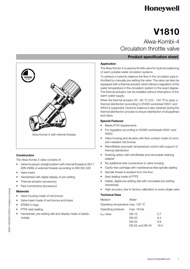
• Valve housing in straight pattern with internal threads to ISO 7 (DIN 2999) or external threads according to DIN ISO 228
• Valve insert
• Handwheel with digital display of pre-setting
• Thermal actuator (accessory)
• Pipe connections (accessory)
Materials
• Valve housing made of red bronze
• Valve insert made of red bronze and brass
• EPDM O-rings
• PTFE seat sealing
• Handwheel, pre-setting dial and display made of plastic, orange
Application
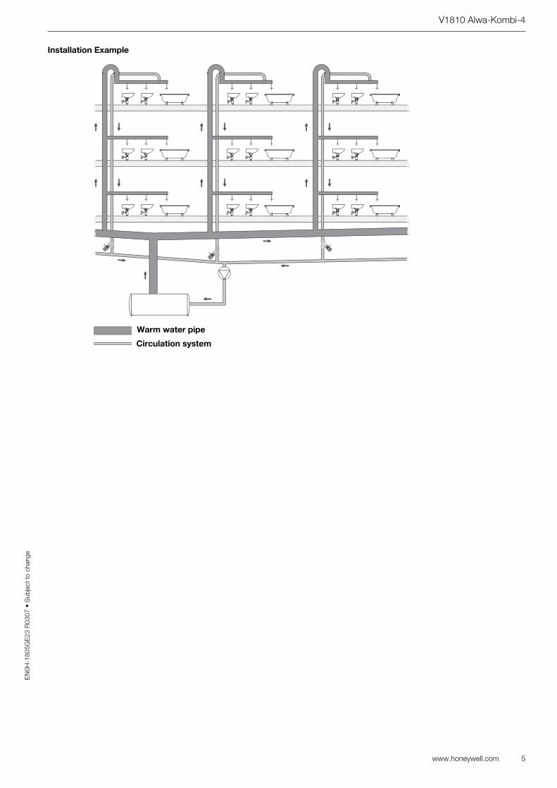
The Alwa-Kombi-4 is used as throttle valve for hydronic balancing of warm potable water circulation systems.
To achieve a hydronic balance the flow in the circulation pipe is throttled by manually pre-setting the valve. The valve can also be equipped with a thermal actuator which allows a regulation of the water temperature in the circulation system to the exact degree. The thermal actuator can be installed without interruption of the warm water supply.
When the thermal actuator 50 - 60 °C (122 - 140 °F) is used, a thermal disinfection according to DVGW worksheet W551 and W553 is supported. Hydronic balance is also retained during the thermal disinfection process to ensure disinfection of all pipelines and risers.
Special Features
• Meets KTW requirements
• For regulation according to DVGW worksheets W551 and W553
• Valve housing and all parts with flow-contact made of corro-sion-resistant red bronze
• Retrofittable automatic temperature-control with support of thermal disinfection
• Draining option with retrofittable and removable draining adapter
• No additional side connections to valve housing
• Cavity-free cartridge with maintenance-free spindle sealing
• Spindle thread is isolated from the flow
• Seat sealing made of PTFE
• Visible, digital pre-setting dial with concealed pre-setting handwheel
• High accuracy due to factory calibration to every single valve
Technical Data
Medium Water
Operating temperature max. 130 °C
Operating pressure max. 16 bar
kvs-value DN 15DN 20DN 25DN 32 und DN 40
2.76.46.816.0
V1810 Alwa-Kombi-4
2 www.honeywell.com
EN
0H-1
805G
E23
R03
07 •
Sub
ject
to c
hang
e
Method of Operation
As throttle valve the Alwa-Kombi-4 limits the flow through the circulation pipe. This is achieved either by manually closing the valve to a certain position or automatically, when the valve is equipped with a thermal actuator.
Manual pre-setting: the valve is pre-set according to a calculated value and stays in that position. The flow of the water is limited by the narrowed valve opening.
Automatic regulation: the valve is equipped with a thermal actuator and pre-set to the desired water temperature. The thermal actuator holds the water temperature at the valve to the exact degree.
When the water temperature falls the valve opens and the flow of warm water increases. When the water temperature rises, the valve closes and shuts-off when the pre-set water temperature is reached (except for a leakage rate).
With manual pre-setting the valve can only be set for optimal operation under „full load“. The automatic regulation process allows a permanent regulation and by that an optimal supply of all pipelines under most economical energy use.
As part of Honeywell´s "Kombi“ family of valves, additional functions can also be fitted and used after the valve has been installed. The functions are carried out by installing adapters into the cartridge spindle:
• The thermal actuator (preferably 50 - 60 °C [122 - 140 °F]) can be installed at any time without interrupting the supply of warm water. The actuator is simply screwed into the spindle and allows permanent hydronic balancing based on the water temperature in the circulation pipe.
• The draining adapter is fitted to drain a pipe or riser and can be removed when the draining process is finished. It can be used with any Alwa-Kombi-4 potable water balancing valve and also with any Honeywell Kombi-3-plus heating/cooling balancing valve.
• The current temperature in the circulation line can be read on the thermometer at any time. The thermometer can be used for variants both with and without a temperature-controlled actuator.
• The sampling valve is used in conjunction with the drain adapter and is used to determine chemical and microbiolo-gical parameters.
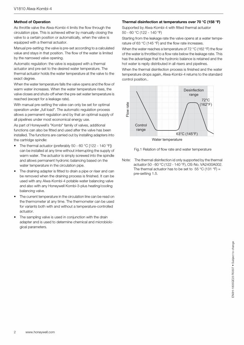
Thermal disinfection at temperatures over 70 °C (158 °F)
Supported by Alwa-Kombi-4 with fitted thermal actuator 50 - 60 °C (122 - 140 °F)
Starting from the leakage rate the valve opens at a water tempe-rature of 63 °C (145 °F) and the flow rate increases.
When the water reaches a temperature of 72 °C (162 °F) the flow of the water is throttled to a flow rate below the leakage rate. This has the advantage that the hydronic balance is retained and the hot water is repily distributed in all risers and pipelines.
When the thermal disinfection process is finished and the water temperature drops again, Alwa-Kombi-4 returns to the standard control position..
Note: The thermal disinfection id only supported by the thermal actuator 50 - 60 °C (122 - 140 °F), OS-No. VA2400A002. The thermal actuator has to be set to 55 °C (131 °F) = pre-setting 1.5.
Fig.1 Relation of flow rate and water temperature
Control
rangeF
low
rate
Water temperature
Desinfection
range
72°C
(162°F)
63°C (145°F)
V1810 Alwa-Kombi-4
www.honeywell.com 3
EN
0H-1
805G
E23
R03
07 •
Sub
ject
to c
hang
e
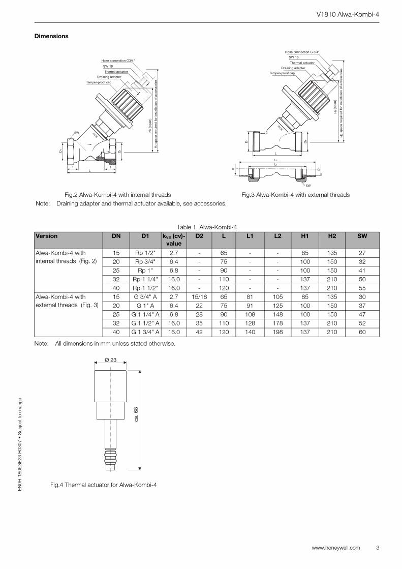
Dimensions
Note: All dimensions in mm unless stated otherwise.
Fig.2 Alwa-Kombi-4 with internal threads Fig.3 Alwa-Kombi-4 with external threadsNote: Draining adapter and thermal actuator available, see accessories.
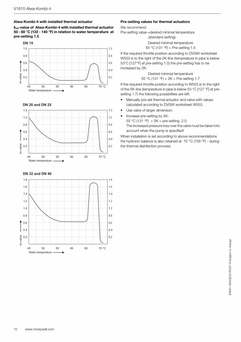
kvs-value of Alwa-Kombi-4 with installed thermal actuator50 - 60 °C (122 - 140 °F) in relation to water temperature atpre-setting 1.5
Pre-setting values for thermal actuators
We recommend:Pre-setting value =desired minimal temperature
(standard setting)
Desired minimal temperature55 °C (131 °F) = Pre-setting 1.5
If the required throttle position according to DVGW worksheet W553 is to the right of the 2K-line (tempreature in pipe is below 53°C [127°F] at pre-setting 1.5) the pre-setting has to be increased by 2K:
If the required throttle position according to W553 is to the right of the 5K-line (temperature in pipe is below 53 °C [127 °F] at pre-setting 1.7) the following possibilities are left:
• Manually pre-set thermal actuator and valve with values calculated according to DVGW worksheet W553.
• Use valve of larger dimension.
• Increase pre-setting by 5K:55 °C (131 °F) + 5K = pre-setting 2.0The increased pressure loss over the valve must be taken into account when the pump is specified!
When installation is set according to above recommendations the hydronic balance is also retained at 70 °C (158 °F) - during the thermal disinfection process.
Water temperature
kv-v
alu
e
Water temperature
kv-v
alu
e
Water temperature
kv-v
alu
e
DN 32 and DN 40
DN 20 and DN 25
V1810 Alwa-Kombi-4
www.honeywell.com 11
EN
0H-1
805G
E23
R03
07 •
Sub
ject
to c
hang
e
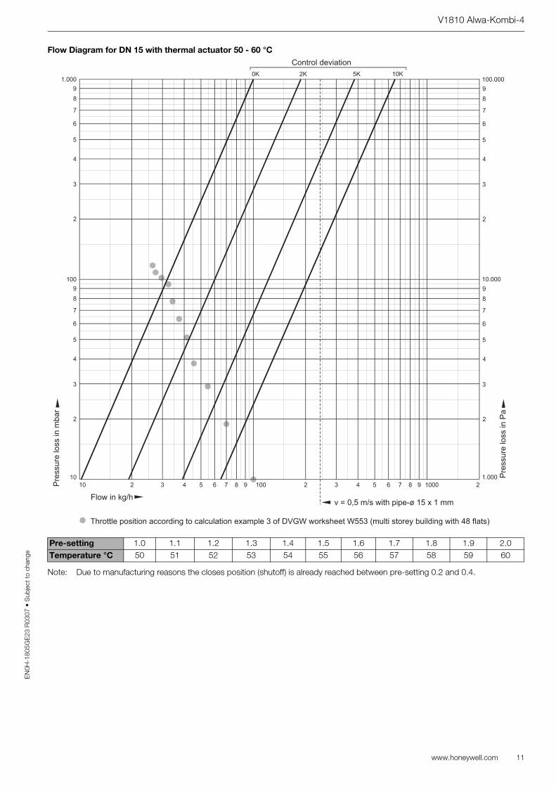
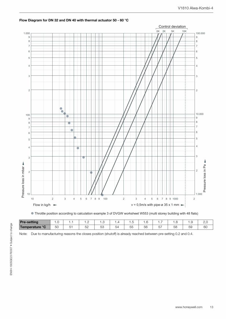
Flow Diagram for DN 15 with thermal actuator 50 - 60 °C
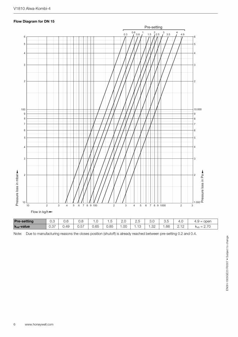
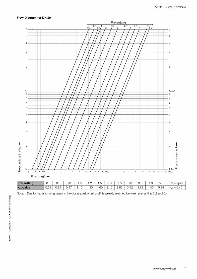
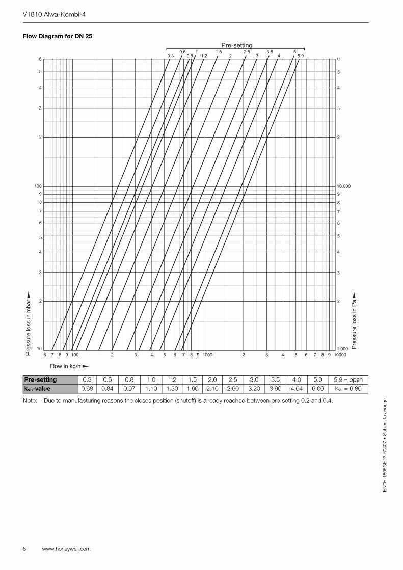
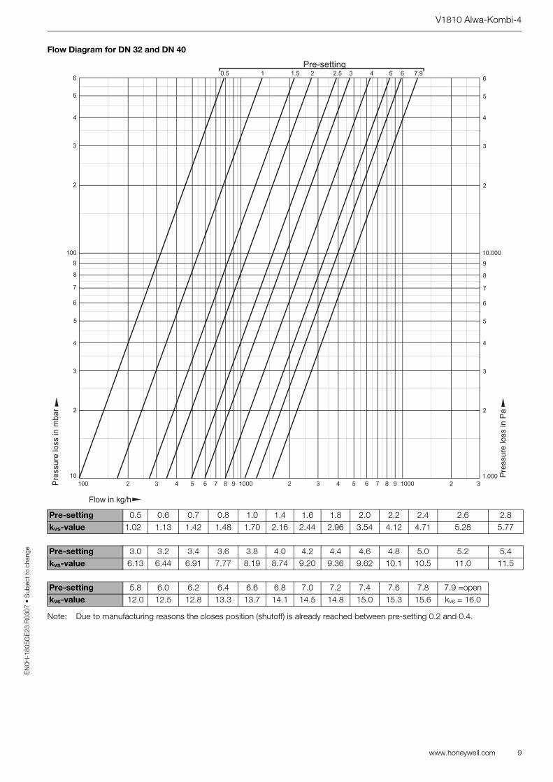
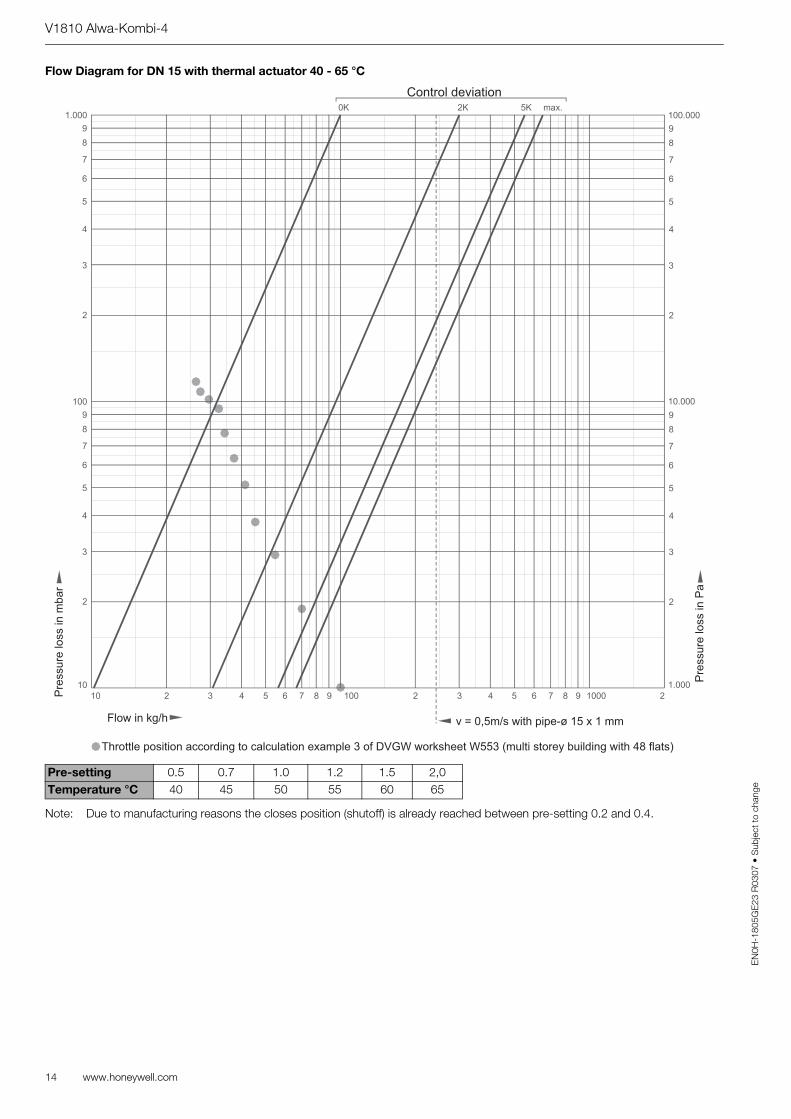
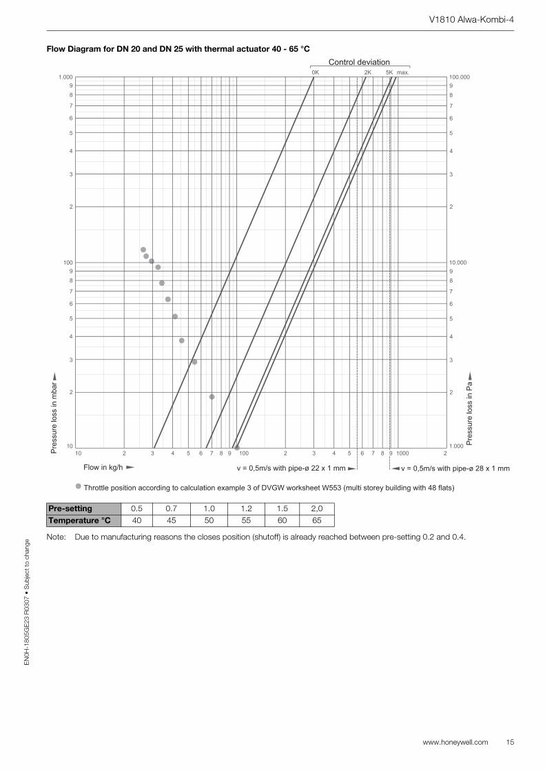
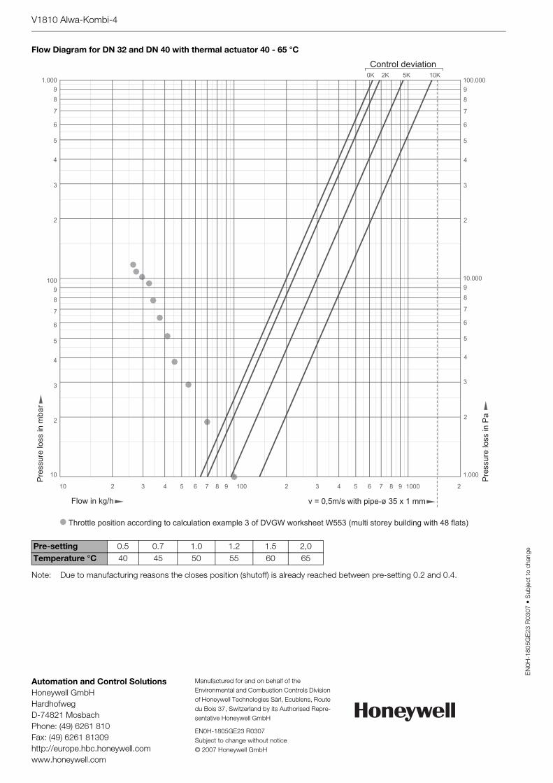
Note: Due to manufacturing reasons the closes position (shutoff) is already reached between pre-setting 0.2 and 0.4.
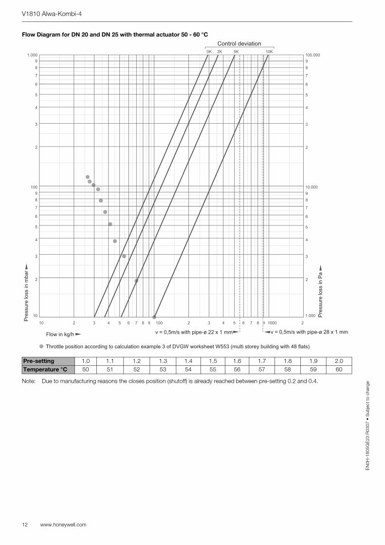
Throttle position according to calculation example 3 of DVGW worksheet W553 (multi storey building with 48 flats)
Automation and Control SolutionsHoneywell GmbHHardhofwegD-74821 MosbachPhone: (49) 6261 810Fax: (49) 6261 81309http://europe.hbc.honeywell.comwww.honeywell.com
Manufactured for and on behalf of the Environmental and Combustion Controls Division of Honeywell Technologies Sàrl, Ecublens, Route du Bois 37, Switzerland by its Authorised Repre-sentative Honeywell GmbH