32
Operating 15088:H 12/23/97 2-1 AM2020 AFP1010 C HAPTER T WO O PERATION

Operating 15088:H 12/23/97 2-1
AM2020AFP1010
CHAPTER TWO
OPERATION

2-2 Operating 15088:H 12/23/97
IntroductionAbout the operation of the panelUse of intelligent and addressable detectors and modules provide the operator with precise information on thelocation of the alarm or trouble, as well as what type of device is reporting the activity.
WARNINGThe AM2020/AFP1010 control panel will only operate with Notifier intelligent addressable devices installed.
All operating power, as well as data communications to and from intelligent and addressable devices, istransmitted on a two-wire LIB Signaling Line Circuit (SLC) Loop that may be wired to meet the requirements ofeither NFPA Style 4 (Class B) or Style 6 or 7 (Class AA)operation. The AM2020 system can be configured with upto 10 LIB SLC Loops and the AFP1010 system with up to 4 Loops, each of which is capable of supporting up to99 intelligent detectors and up to 99 addressable control or monitor modules.
A fire alarm in the AM2020/AFP1010 is initiated by activation of any of the following devices:
• Intelligent smoke or heat detectors (SDX-551/751, SDX-551-TH, CPX-551/751, FDX-551, or IPX-751, etc.).
• Addressable Manual Pull Stations (BGX).• Conventional normally-open or normally-closed contact fire alarm initiating devices connected to addressable MMX Monitor Modules (or equivalent XPM circuits) along a LIB SLC Loop.
During an alarm condition, LEDs on as few as six and as many as 99 addressable initiating devices (smokedetectors, heat detectors, MMX modules etc.) and/or output modules may be latched on. A latched-on LED onan initiating device indicates that the device has caused an activation signal to be transmitted to the AM2020/AFP1010. A latched on LED on an output module indicates that the module has been activated. An activationsignal on the AM2020/AFP1010 includes fire alarms, security alarms, supervisory conditions, or non-alarminputs.
NOTEDuring loss of primary (AC) power, when the AM2020/AFP1010 is operating under secondary
power, only LEDs on intelligent detectors (including DHX-501 duct detectors)will be latched on during a fire alarm.
The AM2020/AFP1010 can be programmed to latch the LEDs on up to99 addressable devices (MMX, CMX, etc.). This software feature canbe used only if ALL installed addressable devices are stamped with thecode R4 on the product marking label (purchased from Notifier afterApril 1, 1991.) Use of this feature under any other circumstances cancause the LIB SLC Loops to shut down during a fire alarm condition. RA-400 Remote LEDs are not permitted for use with this feature (excludingthose wired to DHX-501 Duct Detectors). Use only the RA-400ZRemote LED when extending the number of latched-on LEDs beyondsix. SDX-551 Photoelectric Detectors can also have an H code aftertheir model numbers.
NOTEDetectors have priority over modules. Detectors that come into alarm will assume LED-latch priority
over previously-latched module LEDs.
Output devices (alarm notification appliances, output relays, etc.) are controlled by activation of CMX ControlModules (or equivalent XPC or XPR circuits) connected along the LIB SLC Loop. A control module may serve asa Form-C output relay or as a Notification Appliance Circuit (NAC).
About this ChapterThis chapter covers the operation of the AM2020/AFP1010 Combination Fire/Security Protective SignalingSystem and the control features available to the operator presented through the perspective of the DisplayInterface Assembly (DIA-2020 or DIA-1010).

Operating 15088:H 12/23/97 2-3
This chapter refers to CMX Control Modules and MMX Monitor Modules. If XP Series Transponders are used,unless otherwise stated, the following substitutions may be made:
• MMX Monitor Modules can be substituted with XPM circuits.• CMX Control Modules configured as Form-C contacts (tabs broken), can be substituted with XPR
circuits.• CMX Control Modules not configured as Form-C contacts can be substituted with XPC circuits.
NOTESee warning regarding XP Transponder operation at the beginning of Chapter Three, Section Three. For
more information, refer to the XP Series Transponder System Manual.
About the passwordsThe AM2020/AFP1010 functions in one of three levels—Operational Level, Level One, and Level Two. InOperational mode, the operator may perform the following keypad or menu-displayed functions:
• Acknowledge alarms, troubles, and restorations (clears)• View acknowledged alarms, troubles, and restorations• Silence the sounding of fire alarm notification appliances• Reset the AM2020/AFP1010 System• Test all intelligent addressable detectors in the system• Test the panel's LED indicators, Liquid Crystal Display (LCD), terminal and printer• Read the status of the entire AM2020/AFP1010 system, including the addressable devices• Print out a report on the status of the system or access the history buffer
Access to keypad or menu levels one and two require entry of specific passwords. These levels allow anauthorized programmer to initialize or alter the programming of the AM2020/AFP1010. Level One and Level Twoentry requirements are defined as follows:
Alter Status Level One password required.Programming Level Two password required.
If the main operator of the system requires access to a function which is password protected, contact thedistributor who installed the system for the required password(s). For more information on programming or alteringthe status of the AM2020/AFP1010, refer to Chapter Three of this manual.
Whenever the operator selects a menu, the AM2020/AFP1010 begins a one-minute timer. If no key is pressedduring this minute, the function selected will be aborted and control will return to the state the panel was in prior toselection of that menu.
NOTEUnacknowledged points must be acknowledged prior to being reprogrammed. Any new trouble or alarm
reports reviewed during programming may disrupt the programming process.
About the softwareDepending on the particular release of software in your system, some menu functions and system features maynot be operable. If you attempt to execute a function not operable, the panel will respond with the message"FUNCTION NOT ENABLED. "
Following are general terms used for specific part numbers:
• PRN is used for PRN-4• CRT is used for CRT-2• CMX is used for CMX-1 or CMX-2• MMX is used for MMX-1 or MMX-101
2-4 Operating 15088:H 12/23/97
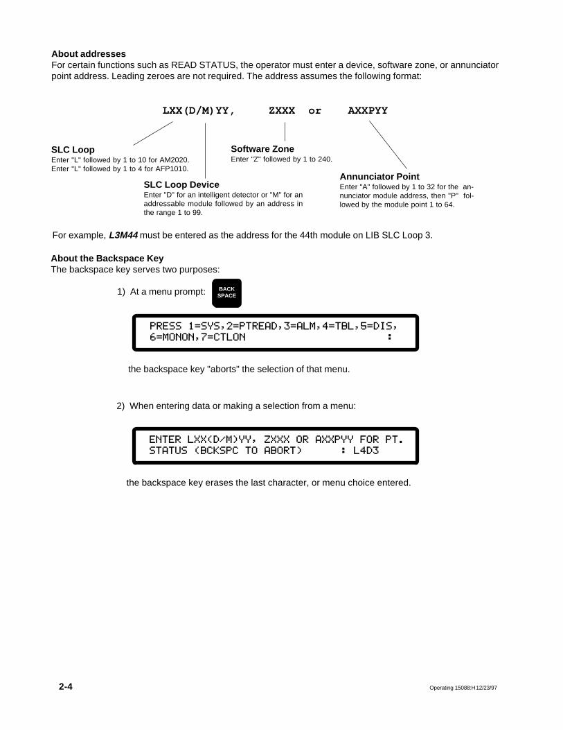
About the Backspace KeyThe backspace key serves two purposes:
1) At a menu prompt:
About addressesFor certain functions such as READ STATUS, the operator must enter a device, software zone, or annunciatorpoint address. Leading zeroes are not required. The address assumes the following format:
LXX(D/M)YY, ZXXX or AXXPYY
For example, L3M44 must be entered as the address for the 44th module on LIB SLC Loop 3.
Annunciator PointEnter "A" followed by 1 to 32 for the an-nunciator module address, then "P" fol-lowed by the module point 1 to 64.
SLC Loop DeviceEnter "D" for an intelligent detector or "M" for anaddressable module followed by an address inthe range 1 to 99.
Software ZoneEnter "Z" followed by 1 to 240.
SLC LoopEnter "L" followed by 1 to 10 for AM2020.Enter "L" followed by 1 to 4 for AFP1010.
BACKSPACE
2) When entering data or making a selection from a menu:
PRESS@1=SYS,2=PTREAD,3=ALM,4=TBL,5=DIS,
6=MONON,7=CTLON :
the backspace key "aborts" the selection of that menu.
the backspace key erases the last character, or menu choice entered.
ENTER@LXX(D/M)YY,@ZXXX@OR@AXXPYY@FOR@PT.
STATUS@(BCKSPC@TO@ABORT)@@@@@@:@L4D3

Operating 15088:H 12/23/97 2-5
About entering alphanumericsMost of the keys on the DIA keypad serve more than one function. For instance, the 3 key is used to enter thedigit 3 or the letter D when entering the address of a detector.
The AM2020/AFP1010 toggles which character is displayed on the LCD with each successive keypress of thatsame key. This allows the operator to press a particular key until the desired character is displayed. Thatcharacter is entered into the display whenever the next, different, key is pressed. If two of the characterscontained on a particular key (for instance, the D and the 3) need to be entered in succession, the ALPHA ENTERkey must be used (see example that follows). After the full address has been entered into the display, pressENTER to transfer the display contents to the system for processing.
Example: To enter L8D3,
About Walk TestThe Walk Test function is a service feature that allows one-man testing of devices on any selected LIB. TheWalk Test feature will automatically abort after 15 minutes of inactivity if inadvertently left enabled by the servicerepresentative.
K LSIGNALSILENCE
K LSIGNALSILENCE
O
8
O
8
D
3
ALPHAENTER
D
3
D
3
ENTERPress to transfer the display contents to the AM2020/AFP1010 system for processing.
Press and the letter K will be displayed.
Press again and the K will change to L.
Press and the letter O is displayed to the right of the displayed letter L.
Press again to change the letter O to the digit 8.
Press and the letter D will be displayed to the right of the displayed characters L8. Thepartial address displayed now reads L8D.
Press to enter the letter D into the display.
Press and a second letter D will be displayed to the right of the displayed characters L8D.The partial address displayed now reads L8DD.
Press again to change the second D to the digit 3.The completed address now reads L8D3.

2-6 Operating 15088:H 12/23/97
About the display timeThe AM2020/AFP1010 has a separate time field in the display for each event that occurs in the system.
All Systems Normal: During periods of no activity, the time field reflects the current time. For AM2020/AFP1010systems with NOTI�FIRE�NET™, the time is synchronized every hour by the network master clock (lastAM2020/AFP1010, INA, or NRT node on network to have its time changed).
Single, unacknowledged event: When an event has occurred but has not been acknowledged, and no other eventhas occurred, the CRT terminal and the DIA display the time this event occurred.
Multiple, unacknowledged events: The display will show the actual time that the first unacknowledged eventoccurred. After the first event is acknowledged, the time shown on the display does not represent the time atwhich the event occurred, but instead indicates the time at which the event is displayed.
Single/multiple previously acknowledged events: The time shown for an acknowledged event is the time at whichthat event was last placed in the display by activation of the ack/step key (not the time at which the eventoccurred).
About the print timeOutput from the printer for a particular event (alarm, trouble, acknowledgment, etc.) includes the time the eventwas sent to the printer, which, in most cases, is identical to the time the event occurred. In extreme cases, whenmany events have occurred within a few seconds, the time printed for a particular event may differ from the actualevent time by up to one minute. After events have been acknowledged, only the event history buffer (if enabled)and the system printer will provide a record of the time at which events occurred.
About prioritiesEvery event the AM2020/AFP1010 displays is prioritized. This includes the processing of incoming alarm andtrouble events, acknowledging events, the clearing of events, and acknowledging the clearing of events(receiving unit operation only). Security alarms will increment the trouble counter on the terminal status line ofthe CRT.
NOTESecurity alarms are processed like fire trouble conditions in the AM2020/AFP1010.
The AM2020/AFP1010 processes and displays events under the following priorities, highest priority first:
1) Fire Alarms 8) Cleared Fire Alarms2) Security Alarms 9) Cleared Security Alarms3) Supervisory Signals 10) Cleared Supervisory Signals4) Device Troubles 11) Cleared Device Troubles5) Disabled Zones 12) Cleared Disabled Zones6) System Troubles 13) Cleared System Troubles7) Annunciator Troubles 14) Cleared Annunciator Troubles
In addition, detectors have a higher priority than modules within each detector/module category; the lower theaddress, the higher the priority (see list below). The display of certain events can be pre-empted by others at thetime they are acknowledged. Pay careful attention to the display when acknowledging events.
Node 1, Loop 1 Detector 1, Loop 1 Detector 2, Loop 1 Detector 3 … Loop 10 Detector 99(followed in priority by)
Node 1, Loop 1 Module 1, Loop 1 Module 2, Loop 1 Module 3 … Loop 10 Module 99(followed in priority by)
Node 1, Zone 1, Zone 2, Zone 3… Zone 240(followed in priority by)
Node 1, System Trouble Indices (in Hex) T00, T01, T02… TFF(followed in priority by)
Node 1, Annunciator Trouble Indices (in Hex) N00, N01, N02… NFF

Operating 15088:H 12/23/97 2-7
About System TestSystem Test, or "Detector Test" as it is often referred to, is a manually initiated test of all intelligent detectorsinstalled in the system. When the user presses the system test key the fire panel performs a chamber test ofeach intelligent detector to ensure its proper operation. System test can take up to one minute beforedisplaying its results. There are two types of display:
Each LIB displays the total number of intelligent devices installed on it, as well as the overall system total.
Each failed device is represented by a three digit number. The first digit indicates the LIB number (0=10), andthe last two the device address. If more than ten devices have failed a "+" is shown after the last detectornumber. If more than ten detectors failed, the serviceman would have to repair, replace or disable the tenlisted, and then rerun System Test in order to locate the remaining ones.
About Periodic TestThe fire panel performs a periodic automatic chamber test of all intelligent detectors installed in the system toensure their proper operation. When a detector has failed its automatic chamber test, it will generate a troublemessage as in Section 5.1 with "DET FAILED TEST" in the type of trouble field. The service man would thenhave to repair or replace the indicated device.
DETECTOR TEST:ALL OK
01+05+00+02+00+80
+25+00+06+00 TOT=119 05:00P 05/22/97
DETECTOR TEST FAIL: 110,119,211,213,605,
617,799,815,015,020+ 05:30 05/22/97

2-8 Operating 15088:H 12/23/97
Section OneThe Display Interface Assembly
Section 1.1 Normal Operation
During normal fire alarm operation when no alarms or troubles exist, the system will display the following:
(a description of the READ STATUSand the SPL FUNCT keys follows)
The operator can perform the functions associated with the following keys without having to enter a password:
NOTIFIER A PITTWAY COMPANY
ALL SYSTEMS NORMAL 04:32P 03/01/97
Current Time and DateHour:Minute Month/Day/Year
Custom 40-Character User Label
AREAD
STATUSACKSTEP
SIGNALSILENCE
SYSTEMRESET
SYSTEMTEST
LAMPTEST
S(
SPLFUNCT
Operating 15088:H 12/23/97 2-9
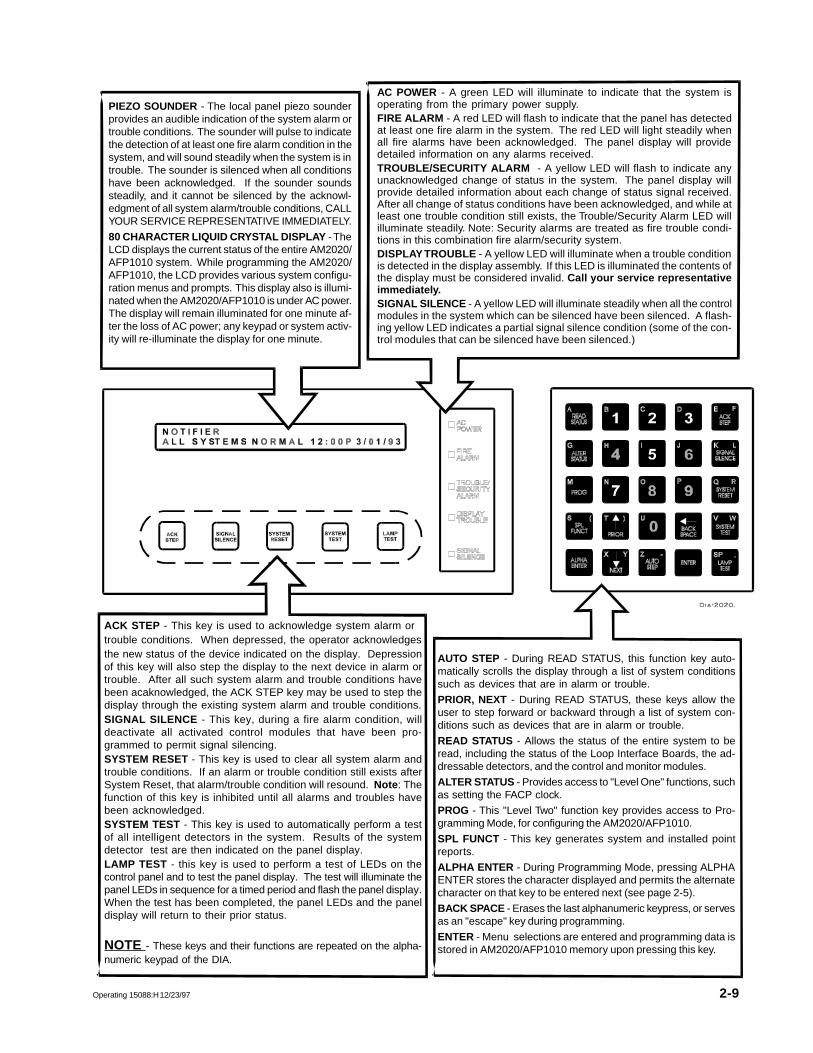
PIEZO SOUNDER - The local panel piezo sounderprovides an audible indication of the system alarm ortrouble conditions. The sounder will pulse to indicatethe detection of at least one fire alarm condition in thesystem, and will sound steadily when the system is introuble. The sounder is silenced when all conditionshave been acknowledged. If the sounder soundssteadily, and it cannot be silenced by the acknowl-edgment of all system alarm/trouble conditions, CALLYOUR SERVICE REPRESENTATIVE IMMEDIATELY.
80 CHARACTER LIQUID CRYSTAL DISPLAY - TheLCD displays the current status of the entire AM2020/AFP1010 system. While programming the AM2020/AFP1010, the LCD provides various system configu-ration menus and prompts. This display also is illumi-nated when the AM2020/AFP1010 is under AC power.The display will remain illuminated for one minute af-ter the loss of AC power; any keypad or system activ-ity will re-illuminate the display for one minute.
AC POWER - A green LED will illuminate to indicate that the system isoperating from the primary power supply.FIRE ALARM - A red LED will flash to indicate that the panel has detectedat least one fire alarm in the system. The red LED will light steadily whenall fire alarms have been acknowledged. The panel display will providedetailed information on any alarms received.TROUBLE/SECURITY ALARM - A yellow LED will flash to indicate anyunacknowledged change of status in the system. The panel display willprovide detailed information about each change of status signal received.After all change of status conditions have been acknowledged, and while atleast one trouble condition still exists, the Trouble/Security Alarm LED willilluminate steadily. Note: Security alarms are treated as fire trouble condi-tions in this combination fire alarm/security system.DISPLAY TROUBLE - A yellow LED will illuminate when a trouble conditionis detected in the display assembly. If this LED is illuminated the contents ofthe display must be considered invalid. Call your service representativeimmediately.SIGNAL SILENCE - A yellow LED will illuminate steadily when all the controlmodules in the system which can be silenced have been silenced. A flash-ing yellow LED indicates a partial signal silence condition (some of the con-trol modules that can be silenced have been silenced.)
ACK STEP - This key is used to acknowledge system alarm ortrouble conditions. When depressed, the operator acknowledgesthe new status of the device indicated on the display. Depressionof this key will also step the display to the next device in alarm ortrouble. After all such system alarm and trouble conditions havebeen acaknowledged, the ACK STEP key may be used to step thedisplay through the existing system alarm and trouble conditions.SIGNAL SILENCE - This key, during a fire alarm condition, willdeactivate all activated control modules that have been pro-grammed to permit signal silencing.SYSTEM RESET - This key is used to clear all system alarm andtrouble conditions. If an alarm or trouble condition still exists afterSystem Reset, that alarm/trouble condition will resound. Note : Thefunction of this key is inhibited until all alarms and troubles havebeen acknowledged.SYSTEM TEST - This key is used to automatically perform a testof all intelligent detectors in the system. Results of the systemdetector test are then indicated on the panel display.LAMP TEST - this key is used to perform a test of LEDs on thecontrol panel and to test the panel display. The test will illuminate thepanel LEDs in sequence for a timed period and flash the panel display.When the test has been completed, the panel LEDs and the paneldisplay will return to their prior status.
NOTE - These keys and their functions are repeated on the alpha-numeric keypad of the DIA.
AUTO STEP - During READ STATUS, this function key auto-matically scrolls the display through a list of system conditionssuch as devices that are in alarm or trouble.
PRIOR, NEXT - During READ STATUS, these keys allow theuser to step forward or backward through a list of system con-ditions such as devices that are in alarm or trouble.
READ STATUS - Allows the status of the entire system to beread, including the status of the Loop Interface Boards, the ad-dressable detectors, and the control and monitor modules.
ALTER STATUS - Provides access to "Level One" functions, suchas setting the FACP clock.
PROG - This "Level Two" function key provides access to Pro-gramming Mode, for configuring the AM2020/AFP1010.
SPL FUNCT - This key generates system and installed pointreports.
ALPHA ENTER - During Programming Mode, pressing ALPHAENTER stores the character displayed and permits the alternatecharacter on that key to be entered next (see page 2-5).
BACK SPACE - Erases the last alphanumeric keypress, or servesas an "escape" key during programming.
ENTER - Menu selections are entered and programming data isstored in AM2020/AFP1010 memory upon pressing this key.

2-10 Operating 15088:H 12/23/97
Section 1.2 Read Status
The Read Status feature of the AM2020/AFP1010 allows the operator to display the status of the entiresystem. To execute READ STATUS:
The display will show:
Enter 1 for Display System Configuration . This selection provides information on any of the systemparameters programmed into the AM2020/AFP1010 - the number and style of the Loop Interface Boards, theAVPS-24s and APS-6Rs, the Software Zone Boundary, the system time delays, annunciator modules installed,etc.
Enter 2 for Point Read . This selection provides information on the status of any intelligent detector,addressable module, software-defined zone or annunciator point in the system.
Enter 3 for Alarm . This selection provides information on the lowest addressed device or zone in a fire alarmstate.
Enter 4 for Trouble . This selection provides information on the lowest addressed device or zone in trouble.
Enter 5 for Disable . This selection provides information on the lowest addressed device or zone disabled.
Enter 6 for Monitor On . This selection provides information on the lowest addressed non-fire or securitymonitor module activated.
Enter 7 for Control On . This selection provides information on the lowest addressed control moduleactivated.
NOTESRead Status options 3, 4, 5, 6, and 7 use the same format as the Point Read option to display their
indicated point information.
For an AM2020/AFP1010 FACP on the NOTI�FIRE�NET system, programming and read statusoperations should always be performed from a Network Reporting Terminal (NRT).
Never attempt to perform programming or read status operations from a local panel when the NRTis simultaneously attempting to do so.
PRESS@1=SYS,2=PTREAD,3=ALM,4=TBL,5=DIS,
6=MONON,7=CTLON @@@ :
PressA
READSTATUS

Operating 15088:H 12/23/97 2-11
4
3
Display System Configuration
Selecting 1 from the Read Status Menu allows the operator to review the various system parameters enteredinto the AM2020/AFP1010. The System Configuration Menu:
READ STATUSMenu Option 1
The default value for SLC Loops not installed is NFPAStyle 4
1
2
Enter Menu Choice: Status Displayed:
VER = Alarm Verification Time (in seconds)SIL = Signal-Silence Inhibit Time (in seconds)CUT = Signal Cut-out Time (in seconds)
THESE@LIB@BOARDS@ARE@INSTALLED:@@
1=Y,2=Y,3=Y,4=Y,5=N,6=N,7=N,8=N,9=N,10=N
Y=installed N=not installed
THE@SLC@LOOP@STYLES@ARE@AS@FOLLOWS:
1=6,2=6,3=6,4=6,5=4,6=4,7=4,8=4,9=4,10=4
VER=60,SIL=045,CUT=0000
THERE@ARE@CURRENTLY@04@AVPS-24@INSTALLED
@IN@THE@SYSTEM
PRESS@1=INST,2=STY,3=TDLY,4=AVPS,5=ZBND,
6=EXTEQ,7=LOCP,8=ISIB,9=PARM :
NOTE: The number "04" in the above display represents the total numberof AVPS and/or APS-6R power supplies installed in the system.
Note that when 4 is chosen from the menu, the total number of AVPS and/or APS-6R power supplies will bedisplayed.

2-12 Operating 15088:H 12/23/97
Enter Menu Choice: Status Displayed:
ZONES 001 - 200 ARE FORWARD ACTIVATED
ZONES 201 - 240 ARE REVERSE ACTIVATED
TS=N@@@@@@@SL=N@@@@@@@APM=N,CMR=N,NAR=N,
LEDL=N,PEC=N,BC=N,PTI=N RPT=N
DPZ=N,LMD=45,LMM=20,LMC=90,72ABCD,71,RC,
BTYP=N,BCAP=12,BSBY=24,ERM=N,BLN=N,PAL=N
5
HIZNDET = High zone for day/night detector sensitivity.LOZNDET = Low zone for day/night detector sensitivity.DVTCNTR = Detector verification trouble counter limit.SER = Is "SACM"/"SEQM" monitor module state reporting enabled?DFT = Is drift compensation enabled?PGR = Is PAGE-1 enabled?MDM = Is modem enabled?NAM = Is the NAM-232 enabled?RP = Is rapid polling enabled?SUP = Is supervisory ACS reporting enabled?
9 HIZNDET=Z150,LOZNDET=Z001,DVTCNTR=15
SER=Y,DFT=Y,PGR=Y,MDM=Y,NAM=N,RP=Y,SUP=Y
8 PRESS 1=INSTL,2=ANN,3=XINT,4=DACT
:
6TS = Is the connection to the terminal supervised? (If TS=N, the terminal will not audibly indicate state changes [i.e., no Bell characters will be sent]).SL = Is the Status Line option enabled?APM = Is the connection to the auxiliary printer monitored?CMR = Is control module state reporting enabled?NAR = Is "NONA"/"NOA" monitor module state reporting enabled?LEDL = LED latches on more activated addressable devices?PEC = Continue to transmit under printer error conditions?BC = Is bidirectional copy enabled?PTI = Is the primary printer trouble inhibited?RPT = Are printer reports directed to terminal output?
7
Option 8 provides you with a Read Status sub-menu for viewing the status of theintelligent SIB, installed annunciators, external interface, or DACT. This menu isdescribed on the next page.
DPZ = Is the piezo disabled during programming?LMD = Local Mode detector address.LMM = Local Mode monitor module address.LMC = Local Mode control module address.72A = Protected premises fire alarm system.72B = Auxiliary fire alarm service.72C = Do not use (see Chapter 2, section 1.1.7)72D = Do not use (see Chapter 2, section 1.1.7)71 = Do not use (see Chapter 2, section 1.1.7)RC = Proprietary supervising station or central station receiving unit.BTYP = Type of battery installed in the system.BCAP = Ni-cad battery capacity.BSBY = Ni-cad battery standby time.ERM = Is event reminder enabled?BLN = Is device blinking enabled?PAL = Is pre-alarm option enabled?

Operating 15088:H 12/23/97 2-13
Enter Option Choice: Status Displayed:
1 ISIB=Y
ISIB = Is the Intelligent Serial Interface Board installed?
NOTEISIBs available for the AM2020/AFP1010 system include the SIB-2048A andSIB-NET. For an AM2020/AFP1010 connected to a NOTI�FIRE�NET�NOTI�FIRE�NET�NOTI�FIRE�NET�NOTI�FIRE�NET�NOTI�FIRE�NET�system however, the only ISIB that can be used is the SIB-NET. If a SIB-NETis not installed, NOTI�FIRE�NET�NOTI�FIRE�NET�NOTI�FIRE�NET�NOTI�FIRE�NET�NOTI�FIRE�NET� specific functions can not be pro-grammed or read under Read Status (see Chapter One).
2 THESE ANNUNCIATORS ARE INSTALLED:
(PRESS ENTER TO CONTINUE UNTIL DONE)
Due to its size, the Annunciator Read Status display is separated into twoscreens, illustrated below. Pressing <ENTER> invokes the next display.
17=Y,18=Y,19=Y,20=N,21=N,22=N,23=N,24=N,
25=N,26=N,27=N,28=N,29=N,30=N,31=N,32=N
UPDN=N,ADDR=010,DBID=BC00D148
MIBA=H,MIBB=H,PORTS=2
UPDN = Is the ACS Port upload/download enabled?ADDR = FACP NOTI�FIRE�NET�NOTI�FIRE�NET�NOTI�FIRE�NET�NOTI�FIRE�NET�NOTI�FIRE�NET� address.DBID = Database identifier.MIBA = MIB-W/WF threshold for Channel A. (On the MIB-WF, onlythe Channel A threshold setting is used.)MIBB = MIB-W threshold for Channel B.PORTS = Number of data ports monitored.
* These items are NOTI�FIRE�NET�NOTI�FIRE�NET�NOTI�FIRE�NET�NOTI�FIRE�NET�NOTI�FIRE�NET� specific functions and areonly displayed when a SIB-NET is installed.
3
Menu Choice 8:
1=Y, 2=N, 3=N, 4=N, 5=Y, 6=Y, 7=N, 8=N,
9=Y,10=N,11=N,12=Y,13=Y,14=Y,15=N,16=N,
DACT=014DACT = Base address of the UDACT (blank for none installed).
***
**

2-14 Operating 15088:H 12/23/97
READ STATUSMenu Option 2Point Read
Selecting 2 from the Read Status Menu allows the operator to review the various detector, module, softwarezone or annunciator point parameters entered into the system. The system prompts the operator for theaddress of the point to be read:
Upon entering the address, the system will display a distinct screen format, depending on the particular typeof device being read, as illustrated below:
NOTEAfter a one-minute timeout, the Control-By-Event (CBE) and the annunciator point mapped addressis displayed for devices and zones. Cooperative Control-By-Event (CCBE) is displayed for reverse
zones. To display this information immediately, press ENTER after the status line appears.
NOTEA detector may be in periodic test during a read status. In this case, the detector status will be
normal but the percentage of alarm threshold will be greater than 100%. If this happens, wait oneminute, then perform another read status.
Detectors
ENTER@LXX(D/M)YY,@ZXXX@OR@AXXPYY@FOR@PT.
@STATUS (BCKSPC TO ABORT) @@@@:
Status: DISABL, ALARM:, TROUBL, NORMAL. Software Type I.D.20-Character Custom Label
NORMAL@SMOKE(ION)@@@@COMPUTER@ROOM@SMOKE
@D@@@A@T@K@@@@@@@SH@V000@H@034@@@@@L02D26
Address
Sensitivity Selection:Low, Medium, High.
Device inTrouble
TrackingSelected
DeviceDisabled
Verification Percentage of Counter Alarm Threshold
Day/Night Detector Sensitivity Setting:Low, Medium, High.
Device inAlarm
Detector VerificationIf verification is enabled for this point, the V indicator appears and the 3-digit counter shows the number of timesthe verification timer was activated for the point without going into alarm. The counter returns to zero when poweris cycled to the IFC-1010/2020 or by following the procedure in the Resetting Sensor Verification Counters sectionof this document. If you disable verification, the counter will retain its last value. If verification is not enabled forthis point, the V indicator does not appear; however, the 3-digit number still appears. Note that the counter doesnot increment unless verification is enabled.

Operating 15088:H 12/23/97 2-15
Control Modules
Monitor Modules
Software Zones
Fire Status: DISABL, ALARM:, TROUBL, NORMAL.Non-fire and Security Status: DISABL, ON, TROUBL, OFF.
Status: DISABL, ALARM:, TROUBL, NORMAL. Software Type I.D. 20-Character Custom Label
ALARM:@FORWARD@ZONE@@ATTIC@DEVICE@ZONE
@D@@@@A@T@@@@@@@@@@@@@@@@@@@@@@@@@@@@Z023
AddressZone in Alarm Zone in TroubleZone
Disabled
*An OFHOOK status indicates that a telephone off-hook (ring-in) signal has been received,but has not been answered by the operator at the fire fighter telephone ACS switchboard.
Status: DISABL, ON, TROUBL, OFF, *OFHOOK, NORMAL. Software Type I.D. 20-Character Custom Label
DISABL@CONTROL@@@@@COMPUTER@ROOM@BELL
@D@CF@A@T@@@W @@@@@@@@@@@@@@@@@S@@L01M36
DeviceActivated
DeviceDisabled
Control ModuleCO = OnCF = Off
AddressDevice inTrouble
Signal Silence Enabled
Walk TestSelected
NORMAL@MONITOR@@@@@@BASEMENT@SMOKES
@D@MO@A@T@K@@@@@@@@@@@@@@@@@@@@@@@L05M12
Software Type I.D. 20-Character Custom Label
AddressTrackingSelected
DeviceDisabled
Monitor Module On(Non-fire and security
types only)
Device inTrouble
Device in Alarm(Active in a non-
fire mode)

2-16 Operating 15088:H 12/23/97
Status: ON, TROUBL, OFF, REQEST*, or blank. 20-Character Custom Label
OFF@@@@ANN@CONTROL@@@ANNUNCIATOR@ONE
@@@@@@@@@@@@@@@@@@@@@@@@@@@@@@@@@@@A01P23
Software Type I.D. Address
Read Status MenuOptions 3 - 7
PRESS 1=SYS,2=PTREAD,3=ALM,4=TBL,5=DIS,
6=MONON,7=CTLON@@@@@@@@@@@@@@@@@@@@@@:@3
DO@YOU@WANT@ZONE@OR@DEVICE@STATUS?
(Y=ZONE,N=DEVICE@(BCKSPC@TO@ABORT))@@:@N
ALARM:@SMOKE(ION)@@@COMPUTER@ROOM@SMOKE
@@@@@@A@@@@@@@@@@@@@@@@@M@034@@@@@L02D26
Option 3 provides information on devices or zones in a fire alarm state. Option 4 provides information ondevices or zones in a trouble state. Option 5 provides information on disabled devices or zones. Option 6provides information on activated non-fire or security monitor modules. Option 7 provides information onactivated control modules. Selecting 3, 4, or 5 from the Read Status Menu prompts the operator to choosebetween zones and devices. The following example performs a search for the lowest device in a fire alarmstate.
NOTEThe control-by-event and the annunciator point mapped address is displayed for devices and zones
after a one minute timeout. In a NOTI�FIRE�NET system, cooperative control-by-event equa-tions are displayed for reverse zones. To display this information immediately, press ENTER
after the status line appears.
Special Status
Annunciator Points
*A REQEST status indicates that a telephone off-hook (ring-in) signal has been received andanswered by the operator at the fire fighter telephone ACS switchboard, but has not beenconnected to the telephone line.

Operating 15088:H 12/23/97 2-17
Section TwoPrior/Next/Auto Step
The Prior, Next, and Autostep keys are used in conjunction with options 2 through 7 of the Read Status Menu.Upon selection of one of these options an address range is defined by the AM2020/AFP1010 for which similarsearches can be performed using the Prior, Next and Autostep Keys. These functions enhance and speed upthe search process, because they eliminate having to re-enter the Read Status Menu for the same functionbeing repeated.
PRIOR - Searches the database in a reverse direction from the current address (refer to note).
NEXT - Searches the database in a forward direction from the current address (refer to note).
AUTOSTEP - Performs an automatic search of the database in the forward direction from the current addresswith a two second display of status line, followed by a two second display of the CBE and annunciator pointmapped address, for each of the points found. (The CCBE equation is displayed for reverse zones on theNOTI•FIRE•NET system.)
NOTEThe control-by-event and the annunciator point mapped address is displayed for devices and zones
after a one minute timeout. The cooperative control-by-event is displayed for reverse zones. Todisplay this information immediately, press ENTER after the status line appears.
The Autostep key can be used as an alternate method for generating special reports.
< Current Address >PRIOR NEXT / AUTOSTEP Ending
SearchAddress
StartingSearchAddress

2-18 Operating 15088:H 12/23/97
Section ThreeSpecial Function
The Special Function feature of the AM2020/AFP1010 allows the operator to generate AM2020/AFP1010status reports or view the AM2020/AFP1010 History Buffer.
SSPL
FUNCTPress The display will show:
PRESS@1=RPTS,2=HIS
@@@@@@@@@@@@@@@@@@@@@@@@@@@@@@@@@@@@@:
Enter 1 for a System Configuration report, 2 for an Installed Point report, 3 for a Fire Alarm report, 4 for aTrouble report, 5 for a Disable report, 6 for a Monitor Module On report (including non-fire and securitymonitor modules), or 7 for a Control Module On report.
The display will show:
Enter 1 to execute the report or 2 to abort a report already in progress.
NOTEOnly one report can be conducted at any one time. The reports are not displayed on the DIA.
Reports are either displayed on the CRT and/or printed by the printer depending on whether or notprinter reports are redirected to the CRT during programming. An example of a report
printout is illustrated in Figure 3-1 .
PRESS@1=SYS,2=POINT,3=ALM,4=TBL,5=DIS,
6=MONON,7=CTLON@@@@@@@@@@@@@@@@@@@@@:
PRESS 1=REQUEST,2=ABORT
@@@@@@@@@@@@@@@@@@@@@@@@@@@@@@@@@@@@:
SPL FUNCTMenu Option 1Reports

Operating 15088:H 12/23/97 2-19
Figure 3-1 AM2020/AFP1010 Special Function Report Printout
PRESS@1=RPTS,2=HIS@@@@@@@@@@@@@@@@@@@@@@@@@@@@@@@@@@@@@@@@@@@@@@@@@@@@@@@@@@@:@1press@1=SYS,2=POINT,3=ALM,4=TBL,5=DIS,6=MONON,7=CTLON@@@@@@@@@@@@@@@@@@@@@@@@:@1PRESS 1=REQUEST,2=ABORT@@@@@@@@@@@@@@@@@@@@@@@@@@@@@@@@@@@@@@@@@@@@@@@@@@@@@@:@1**@SYSTEM@CONFIGURATION@REPORT@BEGIN@**@@@@@@@@@@@@@@@@@@@@@@04:32P@03/01/97THESE@LIB@BOARDS@ARE@INSTALLED:@@@@@@@@@1=Y,2=N,3=N,4=N,5=N,6=N,7=N,8=N,9=N,10=NTHE@SLC@LOOP@STYLES@ARE@AS@FOLLOWS:@@@@@1=4,2=4,3=4,4=4,5=4,6=4,7=4,8=4,9=4,10=4VER=05,SIL=005,CUT=0504THERE@ARE@CURRENTLY@00@AVPS-24@INSTALLED@IN@THE@SYSTEMZONES@001@-@200@ARE@FORWARD@ACTIVATED@@@ZONES@201@-@240@ARE@REVERSE@ACTIVATEDTS=N@@@@@@SL=Y@@@@@@@@APM=Y,CMR=Y,NAR=Y,@LEDL=N,PEC=N,BC=N,PTI=N@@@@@@@@@@ RPT=NDPZ=N,LMD=20,LMM=20,LMC=20,72ABCD,71,RC,BTYP=N,BCAP=12,BSBY=48,ERM=Y,BLN=Y,PAL=NISIB=YTHESE@ANNUNCIATORS@ARE@INSTALLED:@@@@@@@(PRESS@ENTER@TO@CONTINUE@UNTIL@DONE)@1=N,@2=N,@3=N,@4=N,@5=N,@6=N,@7=N,@8=N,@9=N,10=N,11=N,12=N,13=N,14=N,15=N,16=N,17=N,18=N,19=N,20=N,21=N,22=N,23=N,24=N,25=N,26=N,27=N,28=N,29=N,30=N,31=N,32=NUPDN=N,ADDR=010,DBID=BC00d148, @@@@MIBA=H,MIBB=H,PORTS=2DACT=01HIZNDET=Z150,LOZNDET=Z001,DVTCNTR=15 SER=Y,DFT=Y,PGR=Y,MDM=Y,NAM=N,RP=N,SUP=Y***@SYSTEM@CONFIGURATION@REPORT@END@***@@@@@@@@@@@@@@@@@@@@@@04:32P@03/01/97PRESS@1=RPTS,2=HIS@@@@@@@@@@@@@@@@@@@@@@@@@@@@@@@@@@@@@@@@@@@@@@@@@@@@@@@@@@@:@1PRESS@1=SYS,2=POINT,3=ALM,4=TBL,5=DIS,6=MONON,7=CTLON@@@@@@@@@@@@@@@@@@@@@@@@:@2PRESS@1=REQUEST,2=ABORT@@@@@@@@@@@@@@@@@@@@@@@@@@@@@@@@@@@@@@@@@@@@@@@@@@@@@@:@1*****@INSTALLED@POINT@REPORT@BEGIN@*****@@@@@@@@@@@@@@@@@@@@@04:32P@03/01/97ALARM:@FORWARD@ZONE@FIRST@FLOOR@@@@@@@@@@@@@@@A@@@@@@@@@@@@@@@@@@@@@@@@@@@Z001()@@@@@@@@@@@@@@@@@@@@@@@@@@@@@@@@@@@@@@@@@@@@@@@@@@@@@@@@@@@@@@@@@@@@@@@@A01P01
DISABL@REVERSE@ZONE@SECOND@FLOOR@@@@@@@@@D@@@@@T@@@@@@@@@@@@@@@@@@@@@@@@@@Z202OR()@@@@@@@@@@@@@@@@@@@@@@@@@@@@@@@@@@@@@@@@@@@@@@@@@@@@@@@@@@@@@@@@@@@@@@@@A01P02OR()
ALARM:@SMOKE@(ION)@@OFFICE@ARea@@@@@@@@@@@@@@@A@@@@@@@SH@@V010@H@045@@@@@@L01D01(Z01)@@@@@@@@@@@@@@@@@@@@@@@@@@@@@@@@@@@@@@@@@@@@@@@@@@@@@@@@@@@@@@@@@@@@@A01P03
TROUBL@SMOKE(PHOT0)@FACTORY@@@@@@@@@@@@@@@@@@@@T@@@@@@@@@@V000@H@045@@@@@@L01D02(Z202)@@@@@@@@@@@@@@@@@@@@@@@@@@@@@@@@@@@@@@@@@@@@@@@@@@@@@@@@@@@@@@@@@@@@A01P03
NORMAL@HEAT(ANALOG)@MAINTENANCE@@@@@@@@@@@@@@@@@@@@@@@@@@@V000@H@045@@@@@@L01D03(Z01)@@@@@@@@@@@@@@@@@@@@@@@@@@@@@@@@@@@@@@@@@@@@@@@@@@@@@@@@@@@@@@@@@@@@@A01P03
NORMAL@MONITOR@@@@@@FIRST@AID@@@@@@@@@@@@@@@@@@@K@@@@@@@@@@@@@@@@@@@@@@@@@L01m01(Z01)@@@@@@@@@@@@@@@@@@@@@@@@@@@@@@@@@@@@@@@@@@@@@@@@@@@@@@@@@@@@@@@@@@@@@A01P04
ON@@@@@CONTROL@@@@@@FIRST@FLOOR@@@@@@@@@@@@CO@@@@@W@@@@@@@@@@@@@@@@@@@@@s@L01M02OR(Z01)@@@@@@@@@@@@@@@@@@@@@@@@@@@@@@@@@@@@@@@@@@@@@@@@@@@@@@@@@@@@@@@@@@@@@A01P05
OFF@@@@CONTROL@@@@@@SECOND@FLOOR@@@@@@@@@@@CF@@@@@W@@@@@@@@@@@@@@@@@@@@@S@L01M03OR(Z202)@@@@@@@@@@@@@@@@@@@@@@@@@@@@@@@@@@@@@@@@@@@@@@@@@@@@@@@@@@@@@@@@@@@@A01P06
ON@@@@@ANn@ZONE@@@@@BUILDING@ONE@@@@@@@@@@@@@@@@@@@@@@@@@@@@@@@@@@@@@@@@@@A01P01DISABL@ANN@ZONE@@@@@BUILDING@ONE@@@@@@@@@@@@@@@@@@@@@@@@@@@@@@@@@@@@@@@@@@A01P02ON@@@@@ANN@DETECTOR@BUILDING@ONE@@@@@@@@@@@@@@@@@@@@@@@@@@@@@@@@@@@@@@@@@@A01P03OFF@@@@ANN@MONITOR@@BUILDING@ONE@@@@@@@@@@@@@@@@@@@@@@@@@@@@@@@@@@@@@@@@@@A01P04ON@@@@@ANN@CONTROL@@BUILDING@ONE@@@@@@@@@@@@@@@@@@@@@@@@@@@@@@@@@@@@@@@@@@A01P05OFF@@@@ANN@CONTROL@@BUILDING@ONE@@@@@@@@@@@@@@@@@@@@@@@@@@@@@@@@@@@@@@@@@@A01P06******@INSTALLED@POINT@REPORT@END@******@@@@@@@@@@@@@@@@@@@@@04:32P@03/01/97
The special function report printouts (refer to Figure 3-1 ) assume the same display format as the Point Readoption under Read Status . For a description of the various report fields, refer to Point Read .Note: APS-6Rs will be counted as AVPSs in the Special Function Report Printout.

2-20 Operating 15088:H 12/23/97
READ STATUSMenu Option 2The History Buffer
PRESS@1=PRINT,2=DISPLAY,3=STEP,4=RANGE/
STATUS@@@@@@@@@@@@@@@@@@@@@@@@@@@@@@:
Choices 1, 2, and 3 will prompt the user for the beginning and end of the History Bufferrange. The maximum number of events that the system can save in the History Bufferis 400.
Enter "1" to produce a printed report of the History Buffer. An example of a HistoryBuffer printout is illustrated in Figure 3-2 .
Enter "2" to perform an automatic display of the History Buffer on the DIA and CRTterminal (if employed).
Enter "3" to perform a manual display of the History Buffer on the DIA and CRT. Usethe ENTER key (on DIA) or RETURN key (on CRT) to advance the display.
Enter "4" to display the History Buffer range (the number of entries contained in thebuffer), and current status (active/inactive).

Operating 15088:H 12/23/97 2-21
Figure 3-2 AM2020/AFP1010 Special Function History Buffer Printout
PRESS@1=RPTS,2=HIS@@@@@@@@@@@@@@@@@@@@@@@@@@@@@@@@@@@@@@@@@@@@@@@@@@@@@@@@@@@:@2PRESS@1=PRINT,2=DISPLAY,3=STEP,4=RANGE/STATUS@@@@@@@@@@@@@@@@@@@@@@@@@@@@@@@@:@1ENTER@FIRST@EVENT@(1@-@008)@@@@@@@@@@@@@@@@@@@@@@@@@@@@@@@@@@@@@@@@@@@@@@@@:@1ENTER@LAST@EVENT@(001@-@008)@@@@@@@@@@@@@@@@@@@@@@@@@@@@@@@@@@@@@@@@@@@@@@@:@8*********@HISTORY@REPORT@BEGIN@*********@@@@@@@@@@@@@@@@@@@@@04:32P@03/01/97ALARM:@SMOKE@(ION)@DETECTOR@ONE@@@@@@@@@@@@@@@@@@@@@@@@@@@@@@04;32P@03/01/97@101ACK@AL@SMOKE@(ION)@DETECTOR@ONE@@@@@@@@@@@@@@@@@@@@@@@@@@@@@@04;32P@03/01/97@101@@@SIGNAL@SILENCE@@@@@@@@REQUESTED@@@@@@@@@@@@@@@@@@@@@@@@@@@04;23P@03/01/97@@@SYSTEM@RESET@@@@@@@@@@ACTIVATED@@@@@@@@@@@@@@@@@@@@@@@@@@@04;32P@03/01/97CLR@AL@SMOKE@(ION)@DETECTOR@ONE@@@@@@@@@@@@@@@@@@@@@@@@@@@@@@04;32P@03/01/97@101ACL@AL@SMOKE@(ION)@DETECTOR@ONE@@@@@@@@@@@@@@@@@@@@@@@@@@@@@@04;32P@03/01/97@101NOTIFIER@TEST@SYSTEM@ONE@@@@@@@@@@@@@@@@ALL@SYSTEMS@NORMAL@@@04;32P@03/01/97DETECTOR@TEST:ALL@OK@@@02+00+00+00+00+00+00+00+00+00@TOT=002@04;32P@03/01/97**********@HISTORY@REPORT@END@**********@@@@@@@@@@@@@@@@@@@@@04:32P@03/01/97
To differentiate between history buffer printouts (refer to Figure 3-2 ) and system printouts, the colon (:) inthe time field has been replaced by the semicolon (;).

2-22 Operating 15088:H 12/23/97
Section FourFire Alarms
The following example illustrates the system format used to display fire alarm conditions:
ALARM:@SMOKE(PHOTO)@@@COMPUTER@ROOM
FOURTEENTH@FLOOR@@@@@@@04:32P@03/01/97@124
Loop Numberin the range 1-9,with 0=Loop 10.
Device Addressin the range 01-99.
Device Status
Software Zone Labelof the first software zonethat the device was mappedto during programming.
Device Type
Detectors:FIXED PHOT DFIXED THER DHEAT(ANALOG)ION DUCT DETSMOKE (ION)SMOKE ION HPSMOKE ION LPSMOKE(COMBO)SMOKE(PHOTO)
Modules:MON NORM CLDMON PULL STAMONITORPULL STATIONSMOKE (CONV)WATER FLOW
NOTEThe piezo sounder will pulse for fire alarm conditions.
Time and DateHour:Minute Month/Day/Year
Custom Device Labelthat was entered duringprogramming.

Operating 15088:H 12/23/97 2-23
Section 4.1 Acknowledging a Fire Alarm
To acknowledge a fire alarm condition at the panel:
ACK
STEPPush and the ALARM: device status will change to
ACK AL (Acknowledged Fire Alarm).
When the fire alarm condition clears (either automatically in the case of devices programmed for Tracking, orby depression of the SYSTEM RESET key), the panel will display CLR AL and the piezo will resound. Toacknowledge the clearing of a fire alarm:
ACK
STEPPush and the CLR AL status will change to
ACL AL (Acknowledged Clear Fire Alarm).
When multiple events have occurred, the system will display the first event that occurred (with the exceptionthat the first fire alarm will always override any previous trouble). When the ACK STEP key is pushed, theoperator will have acknowledged the highest priority event, not necessarily the event that is being displayedon the CRT Monitor and DIA. The acknowledged message for the first prioritized event will be displayed forseveral seconds, followed by display of the next priority unacknowledged event.
NOTES• The piezo sounder will be silenced only after all events have been acknowledged.• Security alarms are treated like fire trouble conditions in the AM2020/AFP1010.• Reset the system using the System Reset Key after all alarms have been investi- gated and subsequently cleared.• Alarm signals from devices not selected for tracking need a system reset in order to clear.
For an AM2020/AFP1010 panel on the NOTI�FIRE�NET system, acknowledgment of any event may beaccomplished from the local fire alarm panel, intelligent network annunciator (INA), or network reportingterminal (NRT). Acknowledging alarms and events from any of these locations automatically providesacknowledgment at all locations. Fire alarm signals are acknowledged individually at the local fire alarmpanel, NRT, or INA. If the same event on the same point occurs on multiple nodes, the event on the node withthe lowest node address has the highest priority. For more information on priorities and acknowledging eventson the NOTI�FIRE�NET system, refer to the INA Manual, Document 15092, or the NRT Manual, Document15090.
2-24 Operating 15088:H 12/23/97
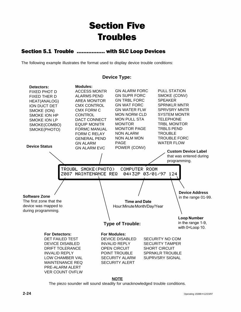
Section 5.1 Trouble ................. with SLC Loop Devices
The following example illustrates the format used to display device trouble conditions:
TROUBL@SMOKE(PHOTO)@@COMPUTER@ROOM
Z087@MAINTENANCE@REQ@@04:32P@03/01/97@124
Software ZoneThe first zone that thedevice was mapped toduring programming.
Loop Numberin the range 1-9,with 0=Loop 10.
Device Addressin the range 01-99.
Device Status
Time and DateHour:Minute Month/Day/Year
NOTEThe piezo sounder will sound steadily for unacknowledged trouble conditions.
GN ALARM FORCGN SUPR FORCGN TRBL FORCGN WAT FORCGN WATER FLWMON NORM CLDMON PULL STAMONITORMONITOR PAGENON ALARMNON ALM MONPAGEPOWER (CONV)
PULL STATIONSMOKE (CONV)SPEAKERSPRNKLR MNTRSPRVSRY MNTRSYSTEM MONTRTELEPHONETRBL MONITORTRBLS PENDTROUBLETROUBLE FORCWATER FLOW
Detectors:FIXED PHOT DFIXED THER DHEAT(ANALOG)ION DUCT DETSMOKE (ION)SMOKE ION HPSMOKE ION LPSMOKE(COMBO)SMOKE(PHOTO)
Device Type:
Modules:ACCESS MONTRALARMS PENDAREA MONITORCMX CONTROLCMX FORM CCONTROLDACT CONNECTEQUIP MONITRFORMC MANUALFORM C RELAYGENERAL PENDGN ALARMGN ALARM EVC
Section FiveTroubles
Custom Device Labelthat was entered duringprogramming.
Type of Trouble:
For Detectors: For Modules:DET FAILED TEST DEVICE DISABLED SECURITY NO COMDEVICE DISABLED INVALID REPLY SECURITY TAMPERDRIFT TOLERANCE OPEN CIRCUIT SHORT CIRCUITINVALID REPLY POINT TROUBLE SPRNKLR TROUBLELOW CHAMBER VAL SECURITY ALARM SUPRVSRY SIGNALMAINTENANCE REQ SECURITY ALERTPRE-ALARM ALERTVER COUNT OVFLW

Operating 15088:H 12/23/97 2-25
Section 5.2 Trouble .................. with Disabled Zones
The following example illustrates the format used to display disabled zone trouble conditions:
TROUBL@FORWARD@ZONE@@@FIRST@FLOOR
@@@@@ZONE@DISABLED@@@@@04:32P@03/01/97Z001
Zone Addressin the rangeZ001-Z240.
Device Status Custom Zone Labelthat was entered duringprogramming.
Time and DateHour:Minute Month/Day/Year
NOTEThe piezo sounder will sound steadily for unacknowledged trouble conditions.
Device Type:FORWARD ZONEREVERSE ZONE
Type of Trouble(Fixed)

2-26 Operating 15088:H 12/23/97
Section 5.3 Trouble ...........................with the AM2020/AFP1010 System
The following example illustrates the format used to display system trouble conditions. For an explanationof some trouble messages, refer to Section Seven.
TROUBL@CATASTROPHIC@LOOP@INTERFACE@BOARD
@2@COMMUNICATION@FLT@04:32P@03/01/97@T19
Time and DateHour:Minute Month/Day/Year
Specific Trouble Message
Trouble IndexProvide this index to yourNotifier Representative fortroubleshooting.
Device Status
NOTEThe piezo sounder will sound steadily for unacknowledged trouble conditions.
Section 5.4 Trouble ..............................with the Annunciators
The following example illustrates the format used to display trouble conditions with the Annunciator ControlSystem modules. For an explanation of some trouble messages, refer to Section Seven.
TROUBL@ANNUNCIATOR@01@INSTALLATION@ERROR
MAIN@LOBBY@@@@@@@@@@@04:32P@03/01/97@N00
Trouble IndexProvide this index to yourNotifier Representative fortroubleshooting.
Device Status Specific Trouble MessageAnnunciator Module
Time and DateHour:Minute Month/Day/Year
Custom Annunciator LabelUser defined during programming.

Operating 15088:H 12/23/97 2-27
PushACK
STEPto execute block acknowledge. The followingmessage will appear:
**********@BLOCK@ACKNOWLEDGE@***********
@@@@@@@@@@@@@@@@@@@@04:32P@03/01/97
CAUTIONFor an AM2020/AFP1010 connected to a NOTI�FIRE�NET system which also includes an NRT oran AFP-200 panel, receiving mode is not supported and block acknowledge should not be disabled.Disabling block acknowledge in this situation will prevent the panel from functioning properly and
alarms will not be acknowledged.
If no NRT or AFP-200 is present on the network, the AM2020/AFP1010 may be configured forreceiving mode or block acknowledge, provided that all other nodes (INAs, AM2020/AFP1010s) on
the system are configured in the same manner.
Section 5.5 Block Acknowledge
The function of block acknowledge gives the user the ability to acknowledge multiple trouble conditions with asingle depression of the ACK STEP key. The AM2020/AFP1010 block acknowledge function is normallyenabled. With block acknowledge enabled, the AM2020/AFP1010 will function as follows:
• Fire Alarm conditions including clears (tracking devices only) must be acknowledged individually asdescribed on the preceding pages. Fire Alarm conditions restored by depression of the system resetkey do not require acknowledgment.
• All current unacknowledged conditions must be processed by the system before block acknowledgeis executed (events will be acknowledged individually until then).
• No acknowledged event messages are recorded for individual troubles once the block acknowledgemessage has been displayed.
• Trouble clears will be recorded for individual troubles that have not been initiated by a system reset.
• Trouble clears no longer have to be acknowledged.
• Troubles may come and go without being acknowledged.
• Upon completion of block acknowledge the AM2020/AFP1010 will enter its display acknowledgedevents mode of operation (see displaying current alarms and troubles section).
To disable the block acknowledge function, refer to the local parameters NFPA programming section inChapter Three of this manual. If the AM2020/AFP1010 block acknowledge function is disabled, the AM2020/AFP1010 will process alarm and trouble conditions in Receiving Unit Mode as described on the preceding andfollowing pages respectively. See caution note below for restrictions.

2-28 Operating 15088:H 12/23/97
Section 5.5A Acknowledging Troubles in Receiving Unit Mode(Block Acknowledge Disabled)
The receiving unit mode of operation is required for all NFPA proprietary supervising station and central stationreceiving units.
To acknowledge a device, zone, system or annunciator module trouble condition:
ACK
STEPPush and the TROUBL status will change to
ACK TB (Acknowledged Trouble).
When the trouble condition clears, the panel will display CLR TB and the piezo will sound again. Toacknowledge the clearing of a trouble condition:
Push ACK
STEPand the CLR TB status will change toACL TB (Acknowledged Clear Trouble).
When multiple events have occurred, the AM2020/AFP1010 will display the first event that occurred (with theexception that the first fire alarm will always override any previous trouble). When the ACK STEP key ispushed, the operator will have acknowledged the highest priority event, not necessarily the event that is beingdisplayed on the CRT Monitor and DIA. The acknowledged message for the first prioritized event will bedisplayed for several seconds, followed by display of the next priority unacknowledged event.
NOTEThe piezo sounder will be silenced only after all events have been acknowledged.
Section 5.6 Displaying Current Alarms and Troubles
To display alarms and troubles that have been acknowledged but not cleared:
Push and the next event in AM2020/AFP1010memory will be displayed on the LCD. Allevents in memory can be reviewed by repeateddepression of the ACK STEP key.
ACK
STEP

Operating 15088:H 12/23/97 2-29
Section SixRemote Peripherals
The AM2020/AFP1010 will support the installation of optional remote Video Display Terminals and printers.
The CRT TerminalThe CRT displays all system information. The CRT can also display system reports if printer reports areredirected to the CRT during programming. The CRT is provided with a keyboard that can be used to programthe AM2020/AFP1010.
Local ApplicationsThe keyboard can be used to operate the AM2020/AFP1010 provided the keyboard is either re-
moved or locked up when not in use.
Receiving Unit ApplicationsIf employed under NFPA 72-1993 Proprietary Fire Alarm System (Receiving Unit) applications, thekeyboard cannot be removed or locked up. The keyboard must remain connected and operationally
functional in the system.
The PrinterThe printer can be used to provide a permanent record of all system events. Alarms, troubles, andacknowledgments are recorded as they occur in the system. In addition, the printer can be used to print outstatus information and system reports.

2-30 Operating 15088:H 12/23/97
Section SevenTrouble Messages
Many of the AM2020/AFP1010 device, zone, system and annunciator trouble messages are self-explanatory.Those messages needing further clarification are listed below. If the system is displaying a message that isnot self-explanatory, and is not listed here, contact your Notifier distributor.
CAT. COMM. FAULTCatastrophic communications failure - the annunciator associated with this message is no longer functioning. Theconnection may be broken.
CAT. FAIL. INCOMPATIBLE SOFTWAREOR INVALID CBEThe panel is operating under an earlier version of software after newer software features have been programmedinto the system. Contact the factory to establish valid software compatibility. Complete reprogramming of systemCBE equations may be required.
CATASTROPHIC LOOP INTERFACE BOARD"X" COMMUNICATION FLTCommunication has failed between the AM2020/AFP1010 and the LIB Board specified in the "X" field of themessage. This failure may be due to several reasons: the LIB Board has failed electronically; the LIB Board isprogrammed but not installed in the system; the LIB Board is installed but is not programmed into the system; or apoor connection has been made between the CPU and the LIB Board.
COMMUNICATION LINK FAILURE IN PORT A*Data is not being received on network (MIB) Port A. This trouble is only reported if the node is configured for dualport monitoring.
COMMUNICATION LINK FAILURE IN PORT B*Data is not being received on network (MIB) Port B. This trouble is only reported if the node is configured for dualport monitoring.
DET FAILED TESTThis detector failed its periodic detector test. The periodic detector test verifies the alarm operation of the detector.This trouble will also be generated when non NOTIFIER devices are detected on the SLC. The detector should beremoved and replaced by an authorized service representative.
DRIFT TOLERANCEThis detector's drift compensation value is outside the allowable range. This detector can no longer be compensatedand should be replaced.
EXPANDER MODULESThe number of annunciator expander modules for this annunciator is less than the number indicated by its DIP switchsettings.
EXT EQP ANN "XX" OR AUDIO/TELEPHONExternal equipment connected to the trouble contacts of an annunciator, AMG or FFT-7 has failed.
INSTALL. ERRORInstallation error with an Annunciator Control System module. An annunciator has been physically installed in anAM2020/AFP1010 system, but has not been programmed; or has been programmed, but not installed.
INVALID REPLYThe AM2020/AFP1010 has received either no response or an invalid response from an addressable LIB SLCLoop device. Confirm that the LIB SLC Loop is connected properly to the device and that the device addresshas been set correctly.
LAN COMMUNICATION FAILURE*The specific network node (panel) can no longer communicate with the rest of the network, indicating aproblem with the network connections.

Operating 15088:H 12/23/97 2-31
LOW CHAMBER VALThe chamber value of the detector is too low for operation. This indicates a malfunction in the detector. Thedetector must be removed and replaced by an authorized service representative.
MAINTENANCE REQThe chamber value of the detector has exceeded 80 percent of the Alarm Threshold (determined by thesensitivity selection of Low, Medium, or High), and has remained there for at least a 26-hour period. Thiscondition may be due to a dirty detector. The detector should be inspected and cleaned as necessary by anauthorized service representative. Failure to do so may eventually result in false alarms.
MANUAL CONTROLThis annunciator is being controlled manually.
PRE-ALARM ALERTThe chamber value of the detector has exceeded 80% of the alarm threshold (determined by the sensitivityselection of Low, Medium or High), and has remained there for at least a 60-second period. This conditionmay be due to a dirty detector. The detector should be inspected and cleaned as necessary by an authorizedservice representative. Failure to do so may eventually result in false alarms.
POINT TROUBLEA monitor module dedicated to monitoring trouble conditions has been activated.
SECURITY ALARMA security device programmed as SARM has been activated indicating a burglary or security violation. Thiscondition should be checked immediately.
SECURITY ALERTA security device programmed as SACM has been activated indicating that a monitored event has occurred.
SECURITY TAMPERA security device programmed as SSYM or SEQM has been activated indicating that monitored equipmenthas been tampered with. This condition should be checked immediately for a SSYM device because it may bedue to a burglary or security violation.
SECURITY NO COMThe AM2020/AFP1010 has received either no response or an invalid response from an addressable SLC loopdevice programmed for security operation. This may be the result of a burglary, other security violation, thefailure of a device, an improperly addressed device, or failure of the field wiring.
SPRNKLR TROUBLEA supervisory condition that indicates sprinkler equipment supervised by a monitor module is in an abnormalstate (i.e. a sprinkler valve has been closed). Note that a break in the wiring of a supervisory circuit is atrouble condition that yields OPEN CIRCUIT, not SPRNKLR TROUBLE.
SUPRVSRY SIGNALA supervisory condition that indicates equipment supervised by a monitor module is in an abnormal state (i.e.low pressure indication). Note that a break in the wiring of a supervisory circuit is a trouble condition thatyields OPEN CIRCUIT, not SUPRVSRY SIGNAL.
VER COUNT OVFLWThis detector has exceeded the allowed detector verification limit. This condition may be due to a dirtydetector. The detector should be inspected and cleaned as necessary by an authorized servicerepresentative. Failure to do so may eventually result in false alarms.
* NOTI�FIRE�NET-specific trouble messages

2-32 Operating 15088:H 12/23/97
Section EightDrift Compensation
Drift CompensationAM2020/AFP1010 software is designed to automatically compensate for chamber sensitivity drift due todetector contamination in SDX-551/751 photo detectors and CPX-551/751 ion detectors. This software-basedcompensation meets NFPA 72-1993, Chapter 7 "Inspection, Testing, and Maintenance" periodic sensitivitytesting and maintenance requirements without removing and testing each smoke detector in an installedsystem. This does not eliminate the need for visual inspection or testing for smoke entry.
Alarm sensitivity in a detector chamber tends to increase over time. This increase is caused by chambercontamination. In time, if the clean air level exceeds the alarm threshold a false alarm occurs. Driftcompensation eliminates this problem by increasing the alarm threshold as needed to maintain constantsensitivity. When the detector is too dirty to compensate, a trouble is indicated automatically.
No additional programming is required for drift compensation. Every detector has three sensitivity levels: low,medium, and high. These levels assign specific "percent obscuration per foot" values for each device.
Drift compensation is executed when:
• The system powers up.• A non-communication INVALID REPLY clears.• Every 120 hours based on at least four samples.
Whenever a detector is replaced, an immediate compensation must be forced. The installer should removethe existing detector, wait for at least three minutes, and then install the new detector.
After servicing a system containing drift compensation software, some detectors may cause a driftcompensation trouble indication within 15 minutes after reapplication of power. These detectors may haveundergone several drift sensitivity adjustments in the past and may not be properly compensated during powerup compensation. A second compensation may be required before the trouble condition clears. This secondcompensation will be completed automatically after 120 hours. If a trouble condition for a detector still existsafter a second compensation, clean and/or replace it.
If power has not been removed and reapplied recently and drift compensation trouble is indicated for aparticular device, clean and/or replace the detector immediately.
ytivitisneSwoL)toofrepnoitarucsbo%(
ytivitisneSmuideM)toofrepnoitarucsbo%(
ytivitisneShgiH)toofrepnoitarucsbo%(
rotceteDotohP 0.2 5.1 0.1
rotceteDnoI 0.3 5.1 0.1


