AM Receiver Circuit : Andy Collinson Email : Description This is a compact three transistor, TRF receiver with fixed feedback. It is similar in principle to the ZN414 which is now replaced by the MK484. The design is simple and sensitivity and selectivity of the receiver are good. Circuit Notes All general purpose transistors should work in this circuit, I used three BC549 transistors in my prototype. The tuned circuit is designed for medium wave, but the circuit will work up to much higher frequencies if a different tuning coil and capacitor are used. I used a ferrite rod and tuning capacitor from an old radio which tuned from approximately 550 - 1600kHz. Q1 and Q2 form a darlington pair featuring high gain and very high input impedance. This is necessary so as not to unduly load the tank circuit. There is only one tuned circuit in this design so sensitivity and selectivity will not be as good as a regenerative or superhet design but good results can still be obtained nonetheless. The 120k feedback resistor impacts on both the gain and input impedance of the circuit so varying this value is a crude way of altering sensitivity and selectivity. In my test circuit Q2 had an emitter voltage of about 0.71V and collector voltage of 1.34V. Home Analysis Help Media Links Practical Schematics Simulation Upda
Transcript
7/17/2019 AM Receiver
http://slidepdf.com/reader/full/am-receiver 1/8
AM Receiver
Circuit : Andy CollinsonEmail :
Description
This is a compact three transistor, TRF receiver with fixed feedback. It is similar inprinciple to the ZN414 which is now replaced by the MK484. The design is simple and
sensitivity and selectivity of the receiver are good.
Circuit Notes
All general purpose transistors should work in this circuit, I used three BC549
transistors in my prototype. The tuned circuit is designed for medium wave, but thecircuit will work up to much higher frequencies if a different tuning coil and capacitor
are used. I used a ferrite rod and tuning capacitor from an old radio which tuned from
approximately 550 - 1600kHz. Q1 and Q2 form a darlington pair featuring high gain
and very high input impedance. This is necessary so as not to unduly load the tank
circuit. There is only one tuned circuit in this design so sensitivity and selectivity will
not be as good as a regenerative or superhet design but good results can still beobtained nonetheless. The 120k feedback resistor impacts on both the gain and input
impedance of the circuit so varying this value is a crude way of altering sensitivity and
selectivity. In my test circuit Q2 had an emitter voltage of about 0.71V and collector
voltage of 1.34V.
Home Analysis Help Media Links Practical Schematics Simulation Upda
For audio amplifiers, Q2 collector would be biased near half supply voltage, however
the input signal levels at RF are tiny, typically 50uV appearing across the coil beingamplified by Q2 and being about 5mV RF across the 2k2 load resistor.
The 120k feedback resistor, between Q2 output and the tank circuit L1 affects overall
performance of the receiver. The value of 120k was found to just enough gain for the
receiver to work well. In strong signal areas its value may be too high and a lower
value of 100k or 82k may weork better; in weak signal areas increasing the value may
work better. Too much feedback and the circuit will become unstable producing a"howling sound". Insufficient feedback and the receiver becomes "deaf". R1 could also
be replaced by a fixed resistor say 33k and a preset resistor of 100k.
Transistor Q3 has a dual purpose; it performs demodulation of the RF carrier whilst at
the same time, amplifying the audio signal. Audio level varies on the strength of thereceived station but I had typically 10-40 mV, this is audio voltage, not RF signal level.
This will directly drive high impedance headphones or can be fed into a suitable
amplifier.
The tuning coil, L1 can be salvaged from an old AM receiver, or to make your ownwind about 50 to 60 turns of 26 SWG enamel coated copper wire over a 3/8 inch
ferrite rod about 3 inches long. This will create a tuning inductor of about 200uH. AM
stations are directional so rotating the rod (or whole receiver) should allow nulling of
some signals whilst boosting others.
If you are in an area of weak reception then an external antenna may be required.
Wind about 4 or 5 turns (indicated as 4 or 5 T on the schematic) of 26 SWG wire ontothe ferrite rod, close to the main winding and connect one end to a cold water tap or
ground connection. Use several feet of flexible wire as an antenna.
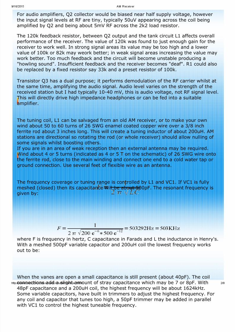
The frequency coverage or tuning range is controlled by L1 and VC1. If VC1 is fully
meshed (closed) then its capacitance will be about 500pF. The resonant frequency isgiven by:
where F is frequency in hertz, C capacitance in Farads and L the inductance in Henry's.
With a meshed 500pF variable capacitor and 200uH coil the lowest frequency works
out to be:
When the vanes are open a small capacitance is still present (about 40pF). The coilconnections add a slight amount of stray capacitance which may be 7 or 8pF. With
48pF capacitance and a 200uH coil, the highest frequency will be about 1624kHz.
Some variable capacitors, have built in trimmers to adjust the highest frequency. For
any coil and capacitor that tunes too high, a 50pF trimmer may be added in parallel
with VC1 to control the highest tuneable frequency.
7/17/2019 AM Receiver
http://slidepdf.com/reader/full/am-receiver 3/8
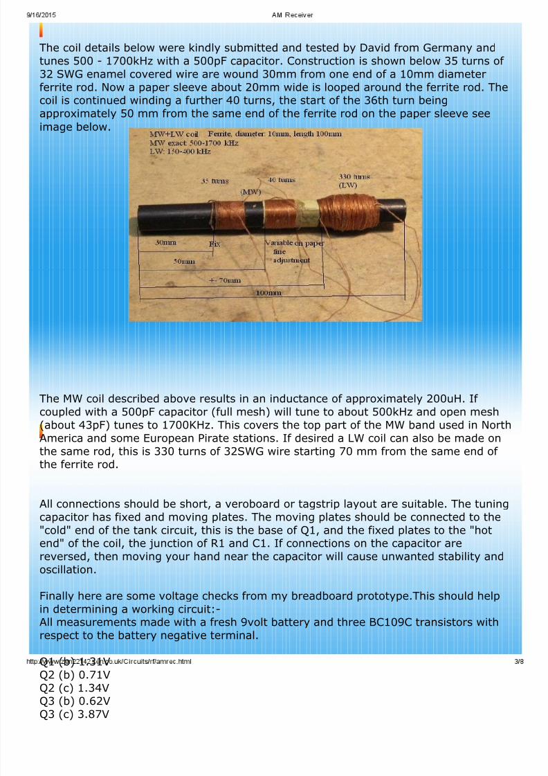
The coil details below were kindly submitted and tested by David from Germany and
tunes 500 - 1700kHz with a 500pF capacitor. Construction is shown below 35 turns of
32 SWG enamel covered wire are wound 30mm from one end of a 10mm diameter
ferrite rod. Now a paper sleeve about 20mm wide is looped around the ferrite rod. Thecoil is continued winding a further 40 turns, the start of the 36th turn being
approximately 50 mm from the same end of the ferrite rod on the paper sleeve see
image below.
The MW coil described above results in an inductance of approximately 200uH. If
coupled with a 500pF capacitor (full mesh) will tune to about 500kHz and open mesh(about 43pF) tunes to 1700KHz. This covers the top part of the MW band used in North
America and some European Pirate stations. If desired a LW coil can also be made on
the same rod, this is 330 turns of 32SWG wire starting 70 mm from the same end of the ferrite rod.
All connections should be short, a veroboard or tagstrip layout are suitable. The tuning
capacitor has fixed and moving plates. The moving plates should be connected to the
"cold" end of the tank circuit, this is the base of Q1, and the fixed plates to the "hot
end" of the coil, the junction of R1 and C1. If connections on the capacitor arereversed, then moving your hand near the capacitor will cause unwanted stability and
oscillation.
Finally here are some voltage checks from my breadboard prototype.This should help
in determining a working circuit:-All measurements made with a fresh 9volt battery and three BC109C transistors with
respect to the battery negative terminal.
Q1 (b) 1.31V
Q2 (b) 0.71VQ2 (c) 1.34VQ3 (b) 0.62V
Q3 (c) 3.87V
7/17/2019 AM Receiver
http://slidepdf.com/reader/full/am-receiver 4/8
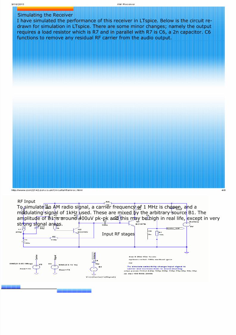
Simulating the Receiver
I have simulated the performance of this receiver in LTspice. Below is the circuit re-
drawn for simulation in LTspice. There are some minor changes; namely the output
requires a load resistor which is R7 and in parallel with R7 is C6, a 2n capacitor. C6
functions to remove any residual RF carrier from the audio output.
RF Input
To simulate an AM radio signal, a carrier frequency of 1 MHz is chosen, and amodulating signal of 1kHz used. These are mixed by the arbitrary source B1. The
amplitude of B1 is around 400uV pk-pk and this may be high in real life, except in very
strong signal areas.
Input RF stages
7/17/2019 AM Receiver
http://slidepdf.com/reader/full/am-receiver 5/8
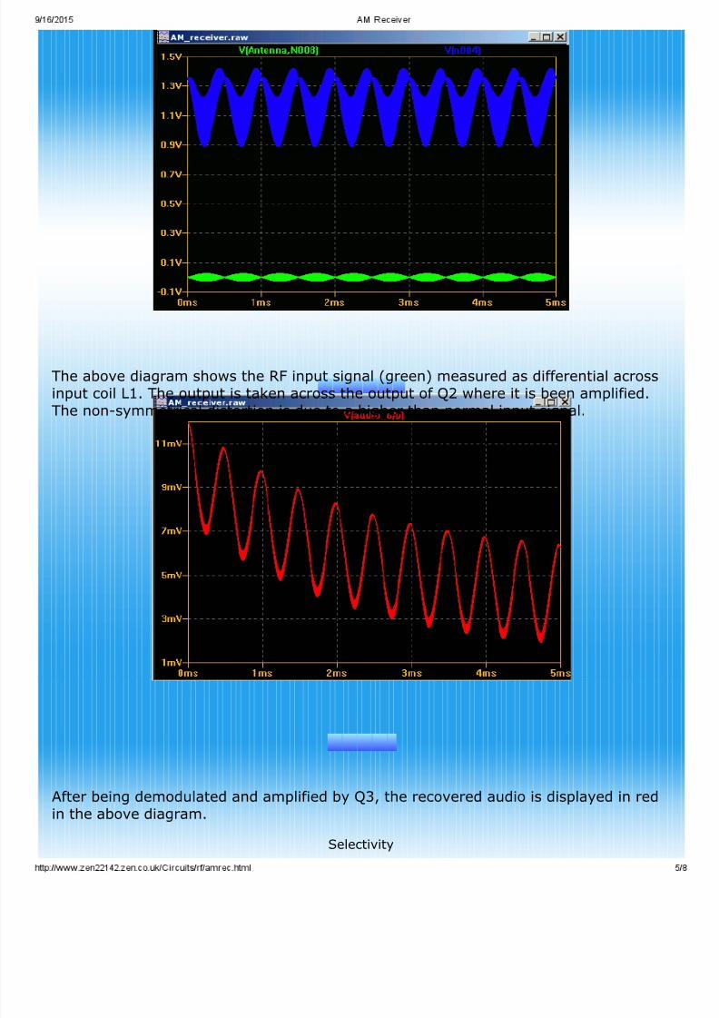
The above diagram shows the RF input signal (green) measured as differential across
input coil L1. The output is taken across the output of Q2 where it is been amplified.
The non-symmetrical distortion is due to a higher than normal input signal.
Audio Output
After being demodulated and amplified by Q3, the recovered audio is displayed in red
in the above diagram.
Selectivity
7/17/2019 AM Receiver
http://slidepdf.com/reader/full/am-receiver 6/8
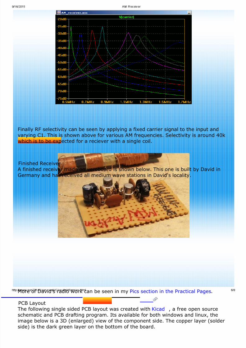
Finally RF selectivity can be seen by applying a fixed carrier signal to the input and
varying C1. This is shown above for various AM frequencies. Selectivity is around 40k
which is to be expected for a reciever with a single coil.
Finished Receiver
A finished receiver made on veroboard is shown below. This one is built by David in
Germany and has received all medium wave stations in David's locality.
More of David's radio work can be seen in my Pics section in the Practical Pages.
PCB LayoutThe following single sided PCB layout was created with Kicad , a free open source
schematic and PCB drafting program. Its available for both windows and linux, the
image below is a 3D (enlarged) view of the component side. The copper layer (solder
side) is the dark green layer on the bottom of the board.
The top view (component side) of the PCB board is shown below. This is without the3D components, the silk screen (drawings on the component side) allow for size of
physical components.
The image below is an actual size (1:1) copy of the copper layer. Note that this isreverse so the veropins appear now on the left hand side at the top. Remember that
this is the lower (solder) side, by viewing the top image you should be able to matchup the positions of all components.
Finally you may not like my layout and prefer to create your own. The follwing
am_rec.zip file, contains the schematic, component list and pcbnew diagram in one
convenient zip file.
Download all files for kicad am_rec.zip
More Construction Tips
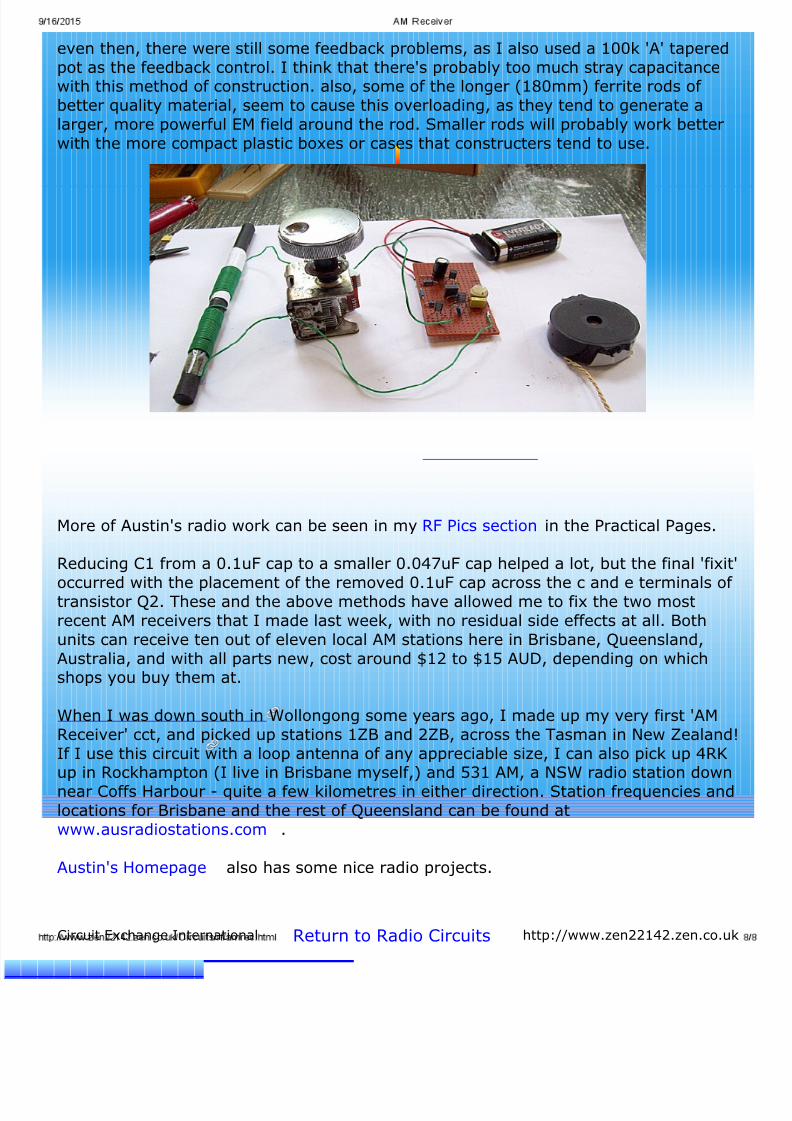
The following tips come from Austin Hellier in Queensland, Australia and may assistwith building this project. Generally speaking, matrix board construction (spread out a
bit) seems best. Recently, when I ran out of it, I was forced to use an 8 x 2 way tag
strip arrangement, which suffered from several problems. Feedback howls and'motorboating' were prominent until I moved the tuning coil and capacitor apart, but
even then, there were still some feedback problems, as I also used a 100k 'A' tapered
pot as the feedback control. I think that there's probably too much stray capacitancewith this method of construction. also, some of the longer (180mm) ferrite rods of
better quality material, seem to cause this overloading, as they tend to generate a
larger, more powerful EM field around the rod. Smaller rods will probably work better
with the more compact plastic boxes or cases that constructers tend to use.
More of Austin's radio work can be seen in my RF Pics section in the Practical Pages.
Reducing C1 from a 0.1uF cap to a smaller 0.047uF cap helped a lot, but the final 'fixit'
occurred with the placement of the removed 0.1uF cap across the c and e terminals of transistor Q2. These and the above methods have allowed me to fix the two most
recent AM receivers that I made last week, with no residual side effects at all. Both
units can receive ten out of eleven local AM stations here in Brisbane, Queensland,
Australia, and with all parts new, cost around $12 to $15 AUD, depending on whichshops you buy them at.
When I was down south in Wollongong some years ago, I made up my very first 'AM
Receiver' cct, and picked up stations 1ZB and 2ZB, across the Tasman in New Zealand!
If I use this circuit with a loop antenna of any appreciable size, I can also pick up 4RKup in Rockhampton (I live in Brisbane myself,) and 531 AM, a NSW radio station down
near Coffs Harbour - quite a few kilometres in either direction. Station frequencies andlocations for Brisbane and the rest of Queensland can be found at
www.ausradiostations.com .
Austin's Homepage also has some nice radio projects.
Circuit Exchange International Return to Radio Circuits http://www.zen22142.zen.co.uk