43
Amateur Radio License Propagation and Antennas
Amateur Radio License
Propagation and Antennas
Todays Topics
• Propagation
• Antennas

Propagation Modes• Ground wave
• Low HF and below, ground acts as waveguide
• Line-of-Sight (LOS)
• VHF and above, radio waves only slightly refracted or reflected by the atmosphere
• Sky wave
• For HF, and sometimes VHF, the upper atmosphere acts as a reflector, bouncing radio waves back to earth far from the source

Line-of-Sight• At VHF and UHF radio waves effectively travel in
straight lines
• Limited by radio horizon
• Slightly refracted by the atmosphere
• Effective earth radius 4/3 the true radius
• From a radio perspective, the earth is slightly flatter

Packard EEto
Cory Hall, UCB
LOS coverage fromPackard
Propagation Path
Cory Hall Packard
EE

Multipath• Radio waves often travel by multiple paths, which
can constructively or destructively interfere
• Small changes in location can result in large changes in signal: “picket fencing”
Building
Airplane
Transmitter Receiver

Tropospheric Ducting• Temperature and humidity inversions can cause the
atmosphere to act as a wave guide
• Frequently in August VHF is ducted from California as far as Hawaii
CaliforniaHawaii
LOSTropospheric
Ducting Atmosphere
Earth
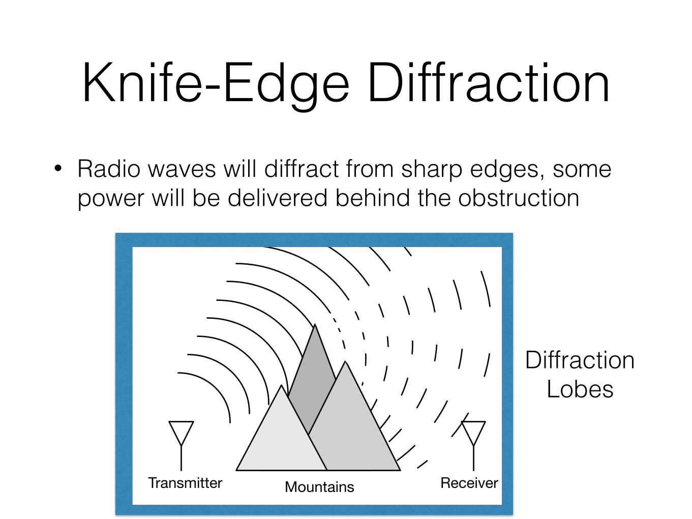
Knife-Edge Diffraction• Radio waves will diffract from sharp edges, some
power will be delivered behind the obstruction
MountainsTransmitter Receiver
Diffraction Lobes

Ionospheric Propagation• Sun ionizes the upper levels of the atmosphere
• Some layers attenuate, others reflect radio waves
• Varies day to night
• Driven by solar activity, number of sunspots (space weather), which varies periodically over a 11 (or 22) year cycle
• Sun has been extraordinarily inactive this cycle
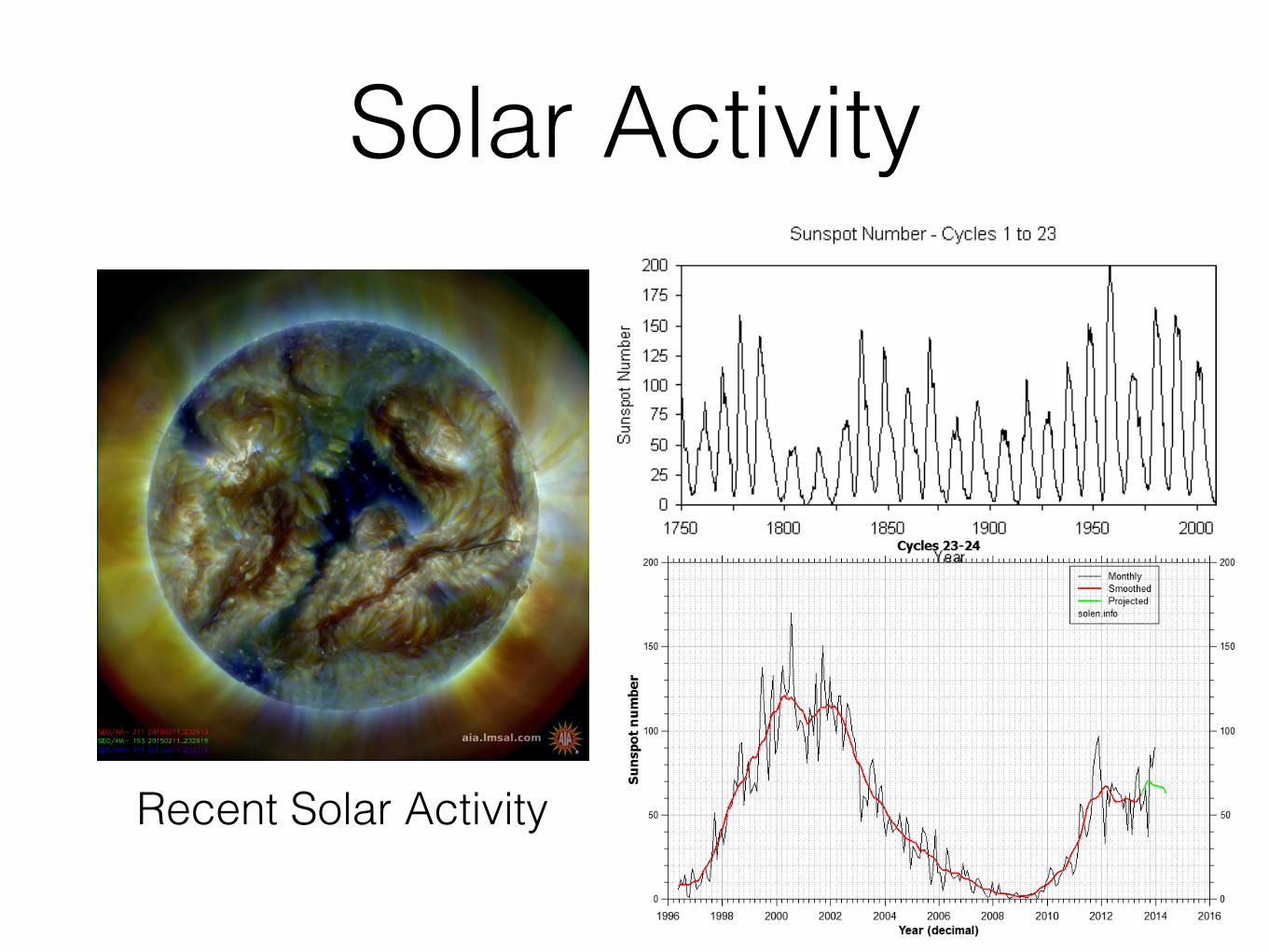
Solar Activity
Recent Solar Activity

Ionosphere• Sun ionizes
atmosphere during daytime
• Layers dissipate and combine at night
• Some layers reflect (E, F), some layers absorb (D)
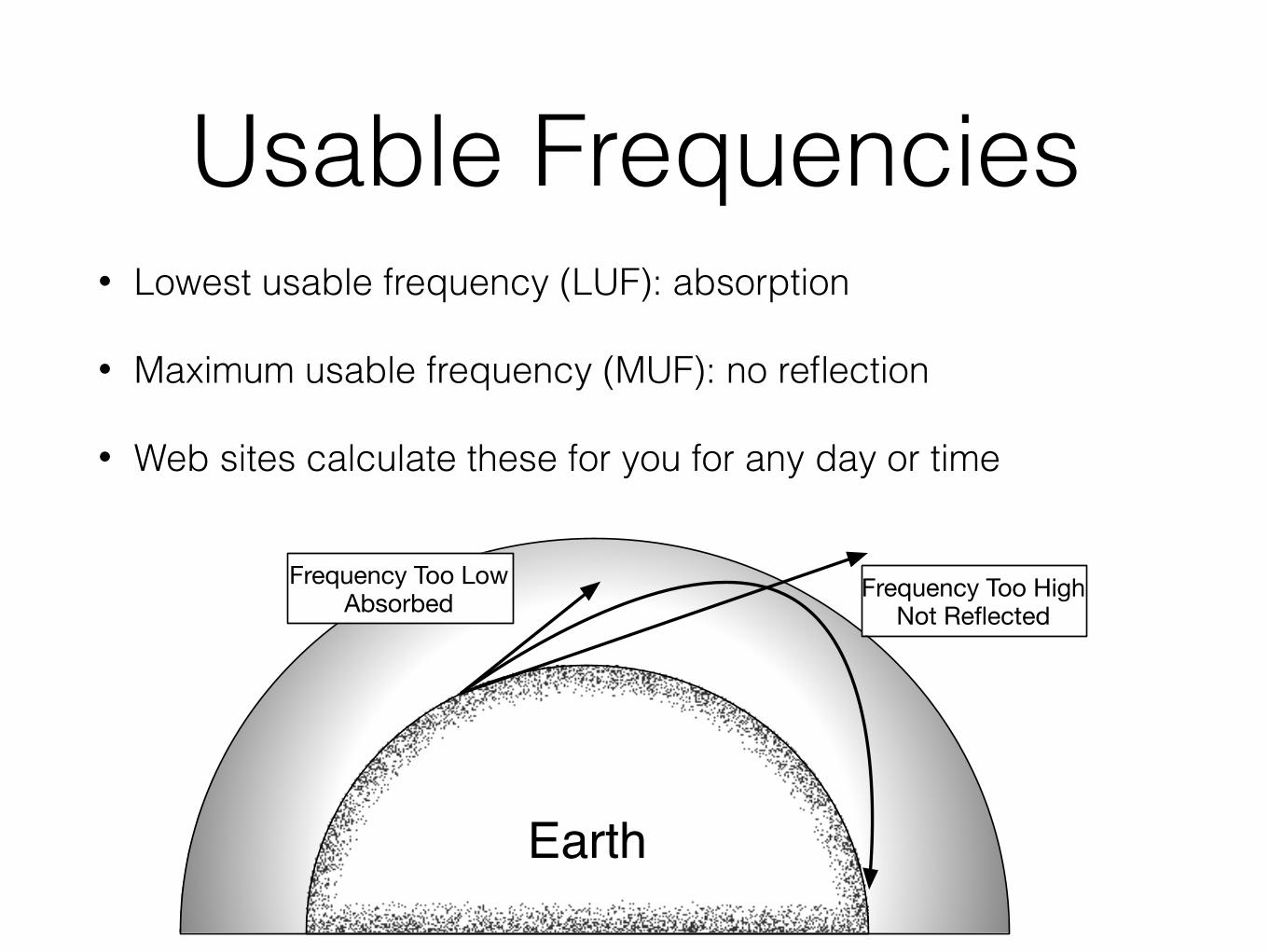
Usable Frequencies• Lowest usable frequency (LUF): absorption
• Maximum usable frequency (MUF): no reflection
• Web sites calculate these for you for any day or time
Earth
Frequency Too LowAbsorbed Frequency Too High
Not Reflected


10 m, 28 MHz : Day

20 m, 14 MHz : Grayline

40 m, 7 MHz : Night
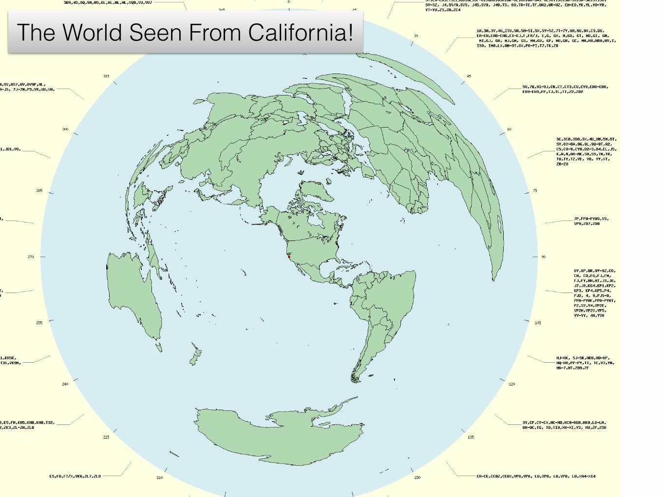
The World Seen From California!
Other Radio Reflectors
• Meteor trails
• Aurora
• Satellites
• Moon
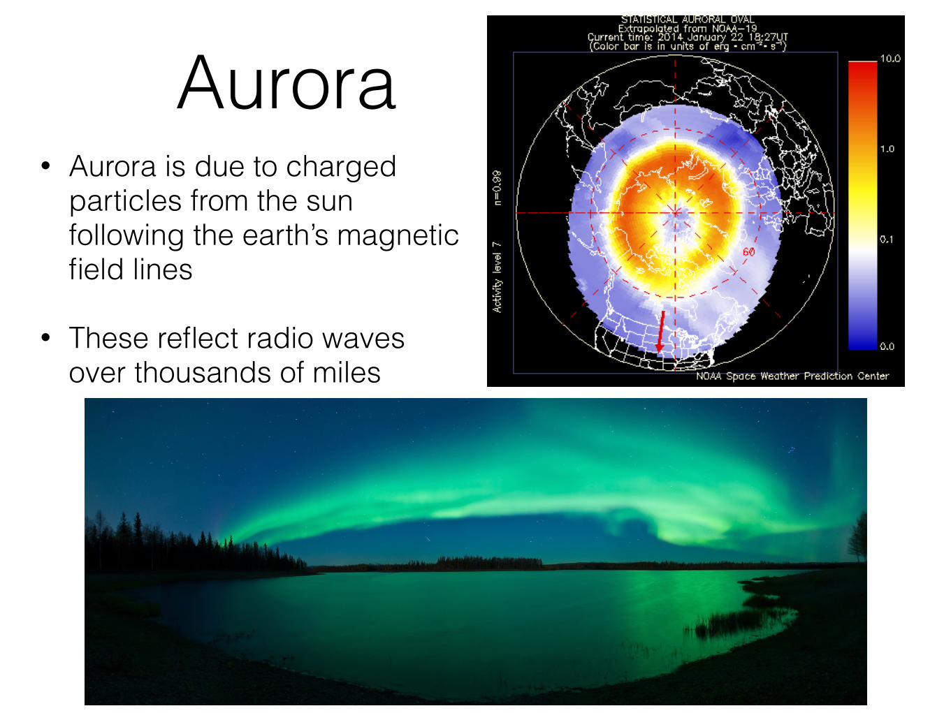
Aurora• Aurora is due to charged
particles from the sun following the earth’s magnetic field lines
• These reflect radio waves over thousands of miles

Antennas
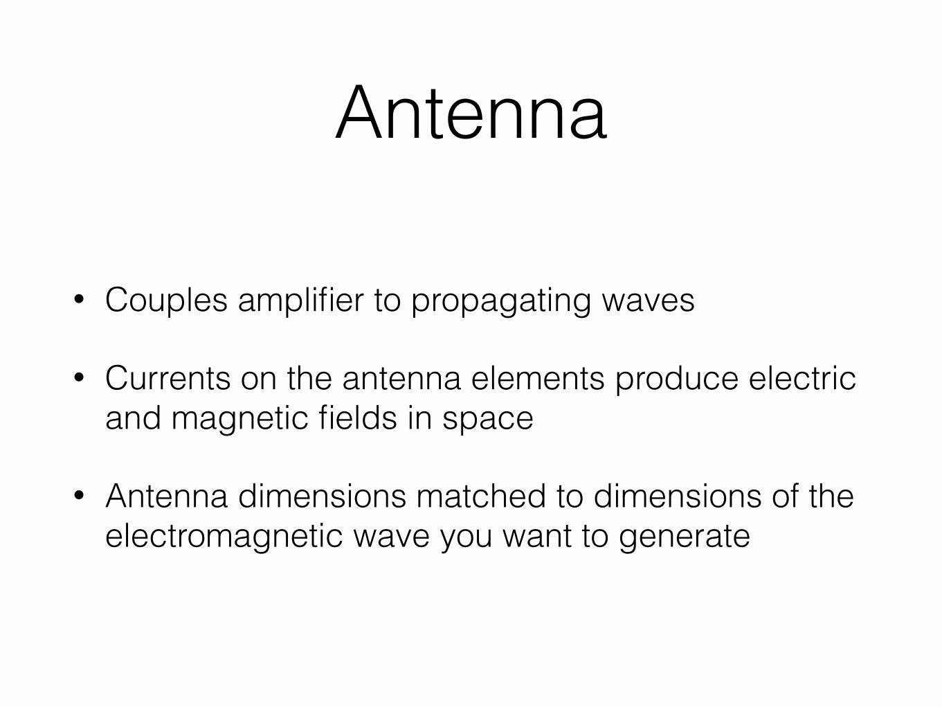
Antenna
• Couples amplifier to propagating waves
• Currents on the antenna elements produce electric and magnetic fields in space
• Antenna dimensions matched to dimensions of the electromagnetic wave you want to generate

Types of Antennas• Omni-directional: no direction preference
• Directional beam: Focuses energy in one direction
• Gain: How much the signal is enhanced in one direction, compared to a reference antenna. Measured in dB, i.e. 10 log10 (P/Pr)
• dBi : compared to an ideal isotropic antenna
• dBd : compared to a dipole antenna
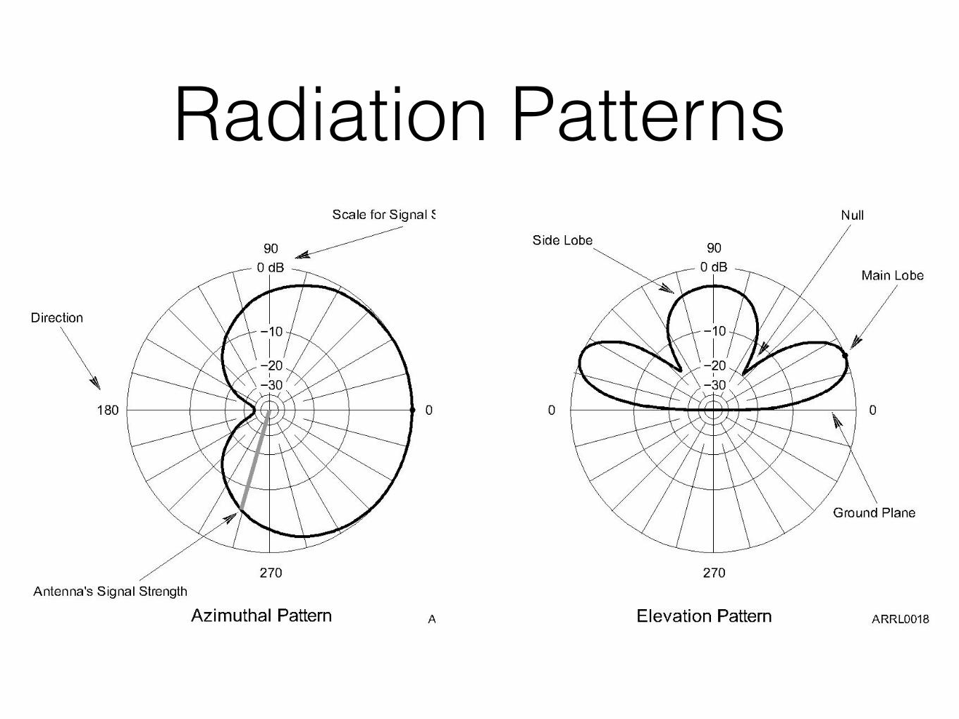
Radiation Patterns

Current in a Conductor• Current flows along conductor
• Electric fields parallel
• Magnetic fields perpendicular
i(t)E(t)
H(t)
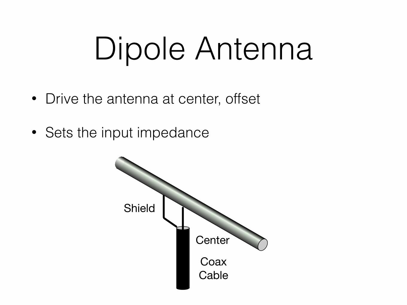
Dipole Antenna• Drive the antenna at center, offset
• Sets the input impedance
CoaxCable
Shield
Center

Dipole Antenna• Sinusoidal input sets up half cycle of current along
antenna
• Length should be 1/2 wavelength for the frequency
CoaxCable
Shield
Center
Input, s(t)
i(t,x)

Dipole Antenna• Oscillating electric field propagates away from
antenna
CoaxCable
Shield
Center
Input, s(t)
ElectricField
PropagationDirection

Dipole Antenna
• Length is 1/2 wavelength of the transmit carrier frequency
• For 150 MHz one wavelength is 2 m, and the antenna should be 1 m long
• For 450 MHz, one wavelength is 67 cm, and the antenna should be 33 cm long
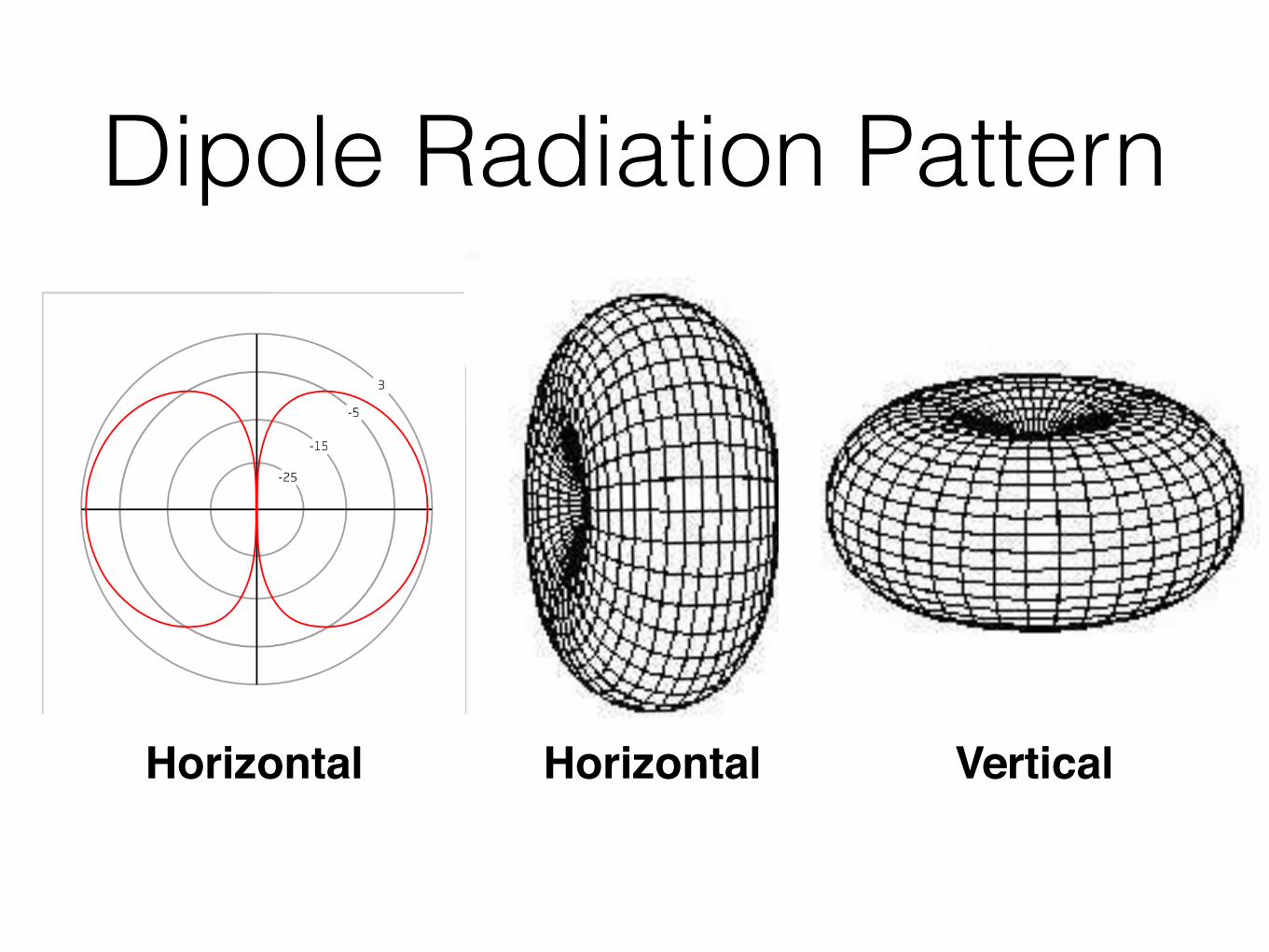
Dipole Radiation Pattern
Horizontal VerticalHorizontal
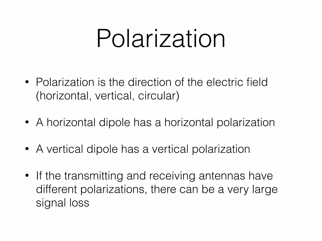
Polarization• Polarization is the direction of the electric field
(horizontal, vertical, circular)
• A horizontal dipole has a horizontal polarization
• A vertical dipole has a vertical polarization
• If the transmitting and receiving antennas have different polarizations, there can be a very large signal loss

1/4 Wave Vertical Antennas
• Conducting surfaces (the earth, your car roof) act as current mirrors
• You get the second half of the antenna for free!
Conducting PlaneConducting Plane
Antenna above Conducting Plane Effective Antenna

1/4 Wave Antennas

Beam Antennas
• Generally one driven element
• Directors to focus energy forward
• Reflectors to cancel out pattern to the rear
Yagi Delta Quad
Feed Lines• Balun
• Duplexer
• Antenna switch
• SWR meter
• Antenna analyzer
• Antenna tuner
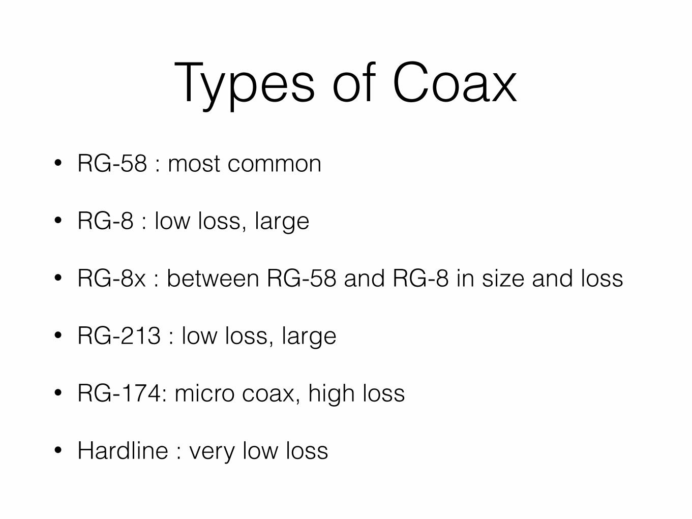
Types of Coax• RG-58 : most common
• RG-8 : low loss, large
• RG-8x : between RG-58 and RG-8 in size and loss
• RG-213 : low loss, large
• RG-174: micro coax, high loss
• Hardline : very low loss
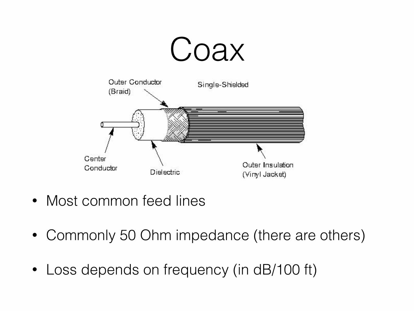
Coax
• Most common feed lines
• Commonly 50 Ohm impedance (there are others)
• Loss depends on frequency (in dB/100 ft)
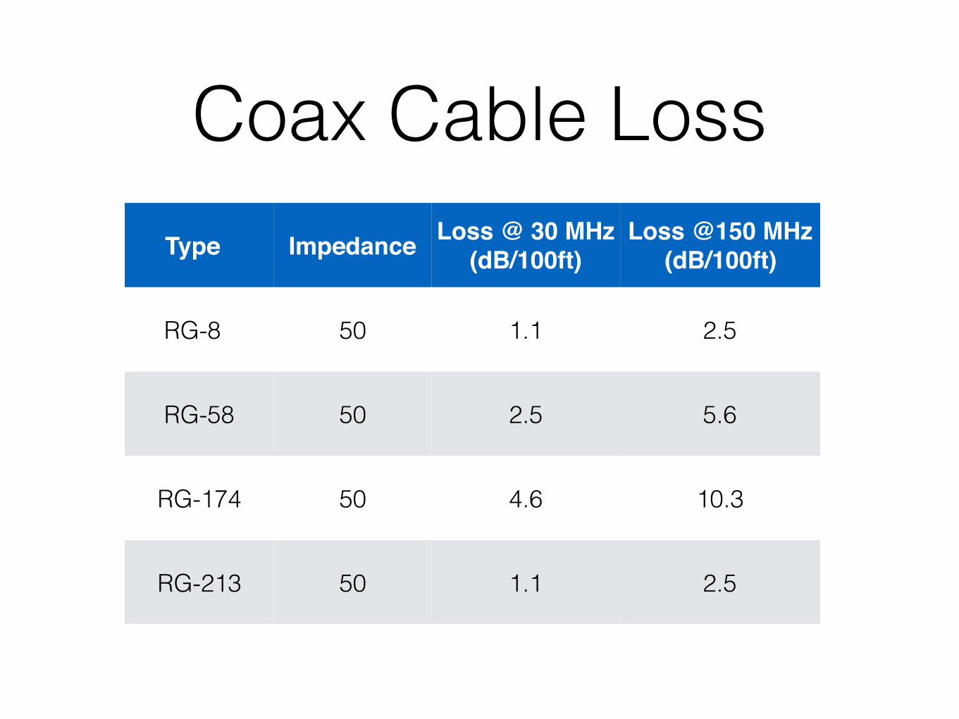
Coax Cable LossType Impedance Loss @ 30 MHz
(dB/100ft)Loss @150 MHz
(dB/100ft)
RG-8 50 1.1 2.5
RG-58 50 2.5 5.6
RG-174 50 4.6 10.3
RG-213 50 1.1 2.5
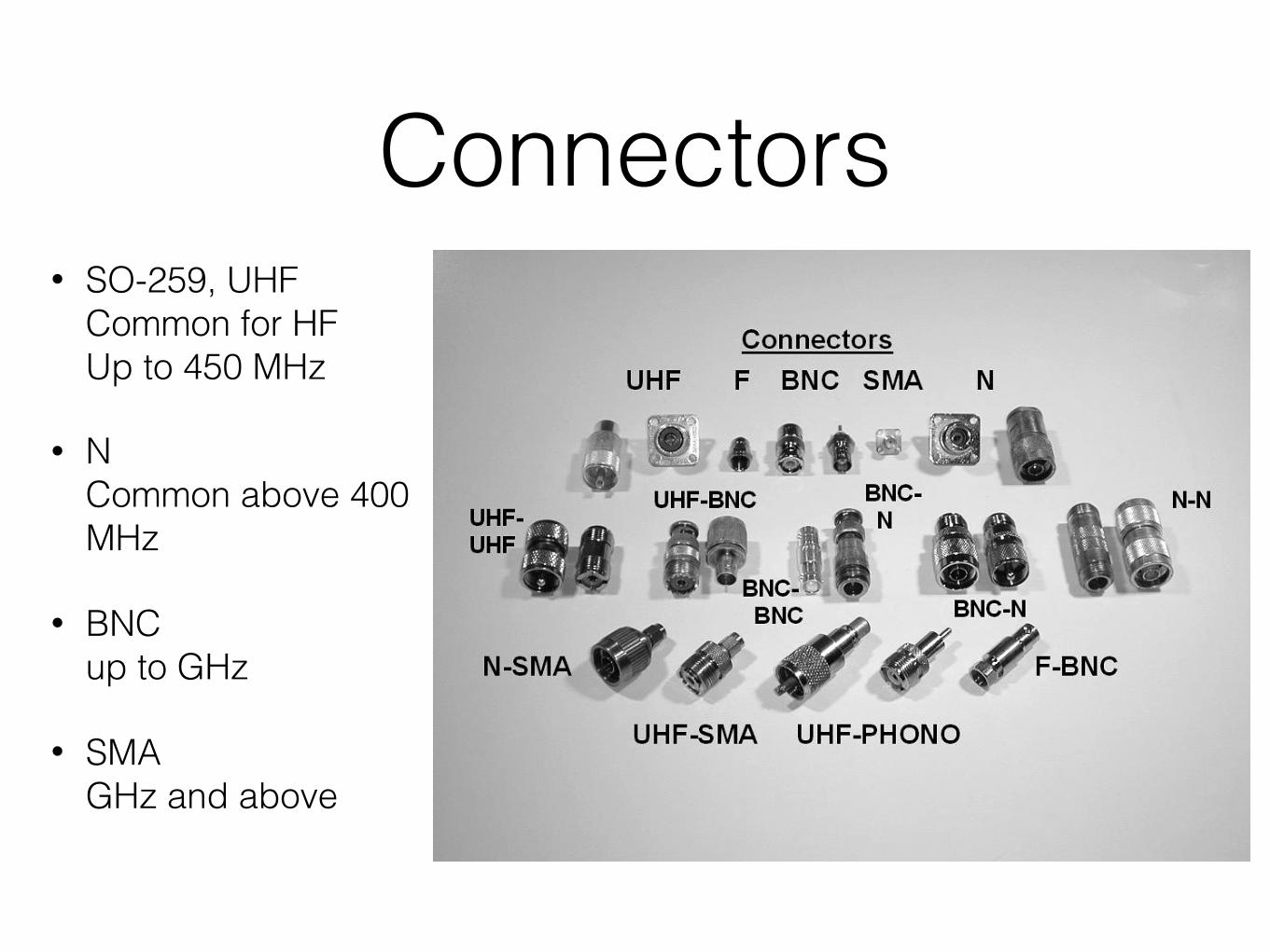
Connectors• SO-259, UHF
Common for HFUp to 450 MHz
• NCommon above 400 MHz
• BNCup to GHz
• SMAGHz and above
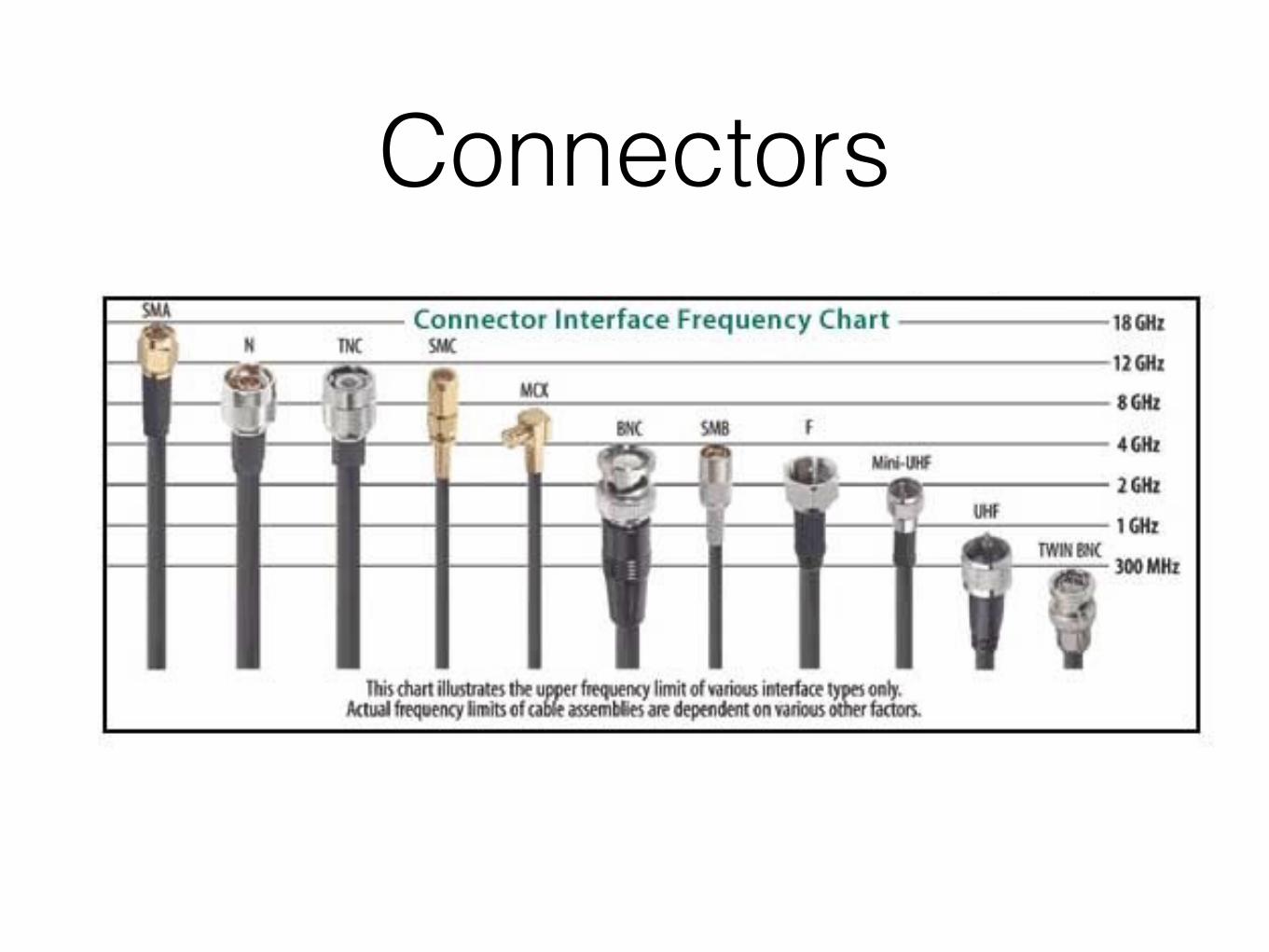
Connectors
Connection to the Antenna• Ideally, all the power from the feed line ends up in the antenna
• The feed line impedance and the antenna input impedance should be matched
• If the impedances are mismatched, some of the power is reflected back to the amplifier
Reduces transmit power
Increases line losses
Reduces amplifier output, can damage the amplifier
Standing Wave Ratio (SWR)
• Ratio of total to forward power
• Always in the for X:1, where X is greater than 1
• Perfect SWR is 1:1
• Semiconductor amps begin have trouble at SWR of 2:1

Antenna Matching• Matching Network : built into the antenna
• Antenna Tuner : adjustable matching networkDoesn’t really tune the antenna
• Antenna Analyzer : measures the antenna input impedance, frequency response
• SWR Meter : measures SWR
• Directional Watt Meter : measures power in one direction, can be used to compute SWR

SWR / Directional Wattmeter
Antenna TunerAntenna Analyzer


