70
User Manual AMAX-5580 High Performance DIN-Rail PC Controller w/ 2xGbE, 1 x mPCIe, 4 x USB, VGA, HDMI

User Manual
AMAX-5580
High Performance DIN-Rail PC Controller w/ 2xGbE, 1 x mPCIe, 4 x USB, VGA, HDMI

AMAX-5580 User Manual ii
CopyrightThe documentation and the software included with this product are copyrighted 2020by Advantech Co., Ltd. All rights are reserved. Advantech Co., Ltd. reserves the rightto make improvements in the products described in this manual at any time withoutnotice. No part of this manual may be reproduced, copied, translated or transmittedin any form or by any means without the prior written permission of Advantech Co.,Ltd. Information provided in this manual is intended to be accurate and reliable. How-ever, Advantech Co., Ltd. assumes no responsibility for its use, nor for any infringe-ments of the rights of third parties, which may result from its use.
AcknowledgmentsIBM, PC/AT, PS/2 and VGA are trademarks of International Business Machines Cor-poration.Intel®, Core™ and Atom™ are the trademarks of Intel CorporationMicrosoft Windows and MS-DOS are registered trademarks of Microsoft Corp.All other product names or trademarks are properties of their respective owners.
Support
For more information on this and other Advantech products, please visit our websitesat: http://www.advantech.comFor technical support and service, please visit our support website at:http://support.advantech.com/
Part No. 2003X55800 Edition 1Printed in Taiwan September 2020
iii AMAX-5580 User Manual
Product Warranty (2 years)Advantech warrants to you, the original purchaser, that each of its products will befree from defects in materials and workmanship for two years from the date of pur-chase. This warranty does not apply to any products which have been repaired or altered bypersons other than repair personnel authorized by Advantech, or which have beensubject to misuse, abuse, accident or improper installation. Advantech assumes noliability under the terms of this warranty as a consequence of such events.Because of Advantech’s high quality-control standards and rigorous testing, most ofour customers never need to use our repair service. If an Advantech product is defec-tive, it will be repaired or replaced at no charge during the warranty period. For out-of-warranty repairs, you will be billed according to the cost of replacement materials,service time and freight. Please consult your dealer for more details.If you think you have a defective product, follow these steps:1. Collect all the information about the problem encountered. (For example, CPU
speed, Advantech products used, other hardware and software used, etc.) Note anything abnormal and list any onscreen messages you get when the problem occurs.
2. Call your dealer and describe the problem. Please have your manual, product, and any helpful information readily available.
3. If your product is diagnosed as defective, obtain an RMA (return merchandize authorization) number from your dealer. This allows us to process your return more quickly.
4. Carefully pack the defective product, a fully-completed Repair and Replacement Order Card and a photocopy proof of purchase date (such as your sales receipt) in a shippable container. A product returned without proof of the purchase date is not eligible for warranty service.
5. Write the RMA number visibly on the outside of the package and ship it prepaid to your dealer.
Declaration of ConformityCE
This product has passed the CE test for environmental specifications when shieldedcables are used for external wiring. We recommend the use of shielded cables. Thiskind of cable is available from Advantech. Please contact your local supplier forordering information.
FCC Class A
Note: This equipment has been tested and found to comply with the limits for a ClassA digital device, pursuant to part 15 of the FCC Rules. These limits are designed toprovide reasonable protection against harmful interference when the equipment isoperated in a commercial environment. This equipment generates, uses, and canradiate radio frequency energy and, if not installed and used in accordance with theinstruction manual, may cause harmful interference to radio communications. Opera-tion of this equipment in a residential area is likely to cause harmful interference inwhich case the user will be required to correct the interference at his own expense.

AMAX-5580 User Manual iv
Technical Support and Assistance1. Visit the Advantech web site at www.advantech.com/support where you can find
the latest information about the product.2. Contact your distributor, sales representative, or Advantech's customer service
center for technical support if you need additional assistance. Please have the following information ready before you call:– Product name and serial number– Description of your peripheral attachments– Description of your software (operating system, version, application software,
etc.)– A complete description of the problem– The exact wording of any error messages
Safety Precaution - Static ElectricityFollow these simple precautions to protect yourself from harm and the products fromdamage. To avoid electrical shock, always disconnect the power from your PC chassis
before you work on it. Don't touch any components on the CPU card or other cards while the PC is on.
Disconnect power before making any configuration changes. The sudden rush of power as you connect a jumper or install a card may damage sensitive elec-tronic components.

v AMAX-5580 User Manual
Safety Instructions1. Read these safety instructions carefully.2. Keep this User Manual for later reference.3. Disconnect this equipment from any AC outlet before cleaning. Use a damp
cloth. Do not use liquid or spray detergents for cleaning.4. For plug-in equipment, the power outlet socket must be located near the equip-
ment and must be easily accessible.5. Keep this equipment away from humidity.6. Put this equipment on a reliable surface during installation. Dropping it or letting
it fall may cause damage.7. The openings on the enclosure are for air convection. Protect the equipment
from overheating. DO NOT COVER THE OPENINGS.8. Make sure the voltage of the power source is correct before connecting the
equipment to the power outlet.9. Position the power cord so that people cannot step on it. Do not place anything
over the power cord.10. All cautions and warnings on the equipment should be noted.11. If the equipment is not used for a long time, disconnect it from the power source
to avoid damage by transient overvoltage.12. Never pour any liquid into an opening. This may cause fire or electrical shock.13. Never open the equipment. For safety reasons, the equipment should be
opened only by qualified service personnel.14. If one of the following situations arises, get the equipment checked by service
personnel: The power cord or plug is damaged. Liquid has penetrated into the equipment. The equipment has been exposed to moisture. The equipment does not work well, or you cannot get it to work according to the user's manual. The equipment has been dropped and damaged. The equipment has obvious signs of breakage.
15. DO NOT LEAVE THIS EQUIPMENT IN AN ENVIRONMENT WHERE THE STORAGE TEMPERATURE MAY GO BELOW -10° C (14° F) OR ABOVE 60° C (140° F). THIS COULD DAMAGE THE EQUIPMENT. THE EQUIPMENT SHOULD BE IN A CONTROLLED ENVIRONMENT.
16. CAUTION: DANGER OF EXPLOSION IF BATTERY IS INCORRECTLY REPLACED. REPLACE ONLY WITH THE SAME OR EQUIVALENT TYPE RECOMMENDED BY THE MANUFACTURER, DISCARD USED BATTERIES ACCORDING TO THE MANUFACTURER'S INSTRUCTIONS.
17. ATTENTION: Danger d'explosion si la batterie est mal REMPLACE. REM-PLACER UNIQUEMENT PAR LE MEME TYPE OU EQUIVALENT RECOM-MANDÉ PAR LE FABRICANT, jeter les piles usagées SELON LES INSTRUCTIONS DU FABRICANT.
18. The sound pressure level at the operator's position according to IEC 704-1:1982 is no more than 70 dB (A).
DISCLAIMER: This set of instructions is given according to IEC 704-1. Advantechdisclaims all responsibility for the accuracy of any statements contained herein.

AMAX-5580 User Manual vi

1 AMAX-5580 User Manual
ContentsChapter 1 Introduction..........................................1
1.1 Introduction ............................................................................................... 21.2 Safety Precautions .................................................................................... 21.3 Accessories............................................................................................... 31.4 Product Specifications............................................................................... 3
1.4.1 AMAX-5580 System Specifications .............................................. 3
Chapter 2 AMAX-5000 System Overview ............5Figure 2.1 Product overview of AMAX-5000 product family ........ 6Figure 2.2 Power System of AMAX-5000 .................................... 7
2.1 Configuration of CPU Module, AMAX-5580.............................................. 8Figure 2.3 Front View of AMAX-5580 .......................................... 8Table 2.1: Legend of configuration of AMAX-5580 CPU module 8Figure 2.4 Internal configuration under the front cover of AMAX-
5580............................................................................ 9Table 2.2: Legend of configuration inside AMAX-5580 CPU mod-
ule............................................................................... 92.2 Module Overview .................................................................................... 10
2.2.1 AMAX-54XX PCIe Expansion Module ........................................ 10Table 2.3: Table 3: List of AMAX-54XX series extension modules
102.2.2 AMAX-50XX EtherCAT I/O Modules........................................... 11
Table 2.4: List of AMAX-50XX series extension modules ......... 11Figure 2.5 AMAX-5000 System Configuration for Motion + Vision
Application ................................................................ 12Table 2.5: AMAX-5000 System Configuration for Motion + Vision
Application ................................................................ 13Figure 2.6 AMAX-5000 System Configuration for Big Data Edge
Concentrator............................................................. 132.3 CPU Types.............................................................................................. 14
Table 2.6: AMAX-5580 Control IPC Product Offering ............... 14Table 2.7: AMAX-5580 CODESYS Ready PAC Product Offering.
142.4 CPU architecture..................................................................................... 15
Figure 2.7 System Architecture of AMAX-5580 ......................... 15
Chapter 3 Initial Setup ........................................173.1 Selecting the Right Power Supply Unit ................................................... 18
Table 3.1: Pin Definition of Power Input Terminal ..................... 183.2 System Configuration and Installation..................................................... 193.3 Mounting ................................................................................................. 21
3.3.1 Attaching the AMAX-54XX left-hand-side module (option) ......... 213.3.2 Permissible installation positions ................................................ 21
Figure 3.1 Mounting position for AMAX-5580............................ 213.3.3 Attaching on the DIN-rail............................................................. 223.3.4 Install the AMAX-50XX right-hand-side modules........................ 22
Figure 3.2 AMAX-5000 installed in control box.......................... 223.4 BIOS Setup ............................................................................................. 22
3.4.1 How to enter the BIOS?.............................................................. 223.4.2 BIOS configuration...................................................................... 23
Figure 3.3 BIOS and processor information .............................. 23
AMAX-5580 User Manual 2
3.4.3 Hardware Monitor ....................................................................... 23Figure 3.4 Configuration list under Advanced tab in BIOS........ 23Figure 3.5 The Hardware Sensors Value showed in BIOS ....... 24Figure 3.6 The CPU shutdown temperature and overheating tem-
perature configuration in BIOS ................................. 24Figure 3.7 EC watch dog timer configuration in BIOS............... 25
3.4.4 Serial port configuration.............................................................. 26Figure 3.8 Serial port configuration in BIOS .............................. 26Figure 3.9 Enabling serial port in BIOS ..................................... 26Figure 3.10Configure serial port protocol type in BIOS .............. 27
3.4.5 Save settings and Return to default............................................ 27Figure 3.11Hotkey to Optimized Defaults and Save & Exit Setup in
BIOS......................................................................... 27
Chapter 4 Software Tools .................................. 294.1 Verinfo..................................................................................................... 304.2 Susi IOT .................................................................................................. 314.3 EAPI........................................................................................................ 324.4 AdvWF .................................................................................................... 324.5 Advantech Lmsensor .............................................................................. 334.6 Advantech Watchdog KMDF Driver ........................................................ 34
Chapter 5 PCIe Expansion Module ................... 355.1 AMAX-5424V 4-port USB3.0 Vision Frame Grabber Module ................. 36
Figure 5.1 AMAX-5424V Module............................................... 365.1.1 AMAX-5424V Specification......................................................... 365.1.2 LED Indicator .............................................................................. 37
Figure 5.2 AMAX-5424V Module LED Indicator ........................ 375.2 AMAX-5490 2-port Isolated RS-232/422/485 Communication Module... 38
Figure 5.3 AMAX-5490 Module ................................................. 385.2.1 AMAX-5490 Specification ........................................................... 385.2.2 LED Indicator .............................................................................. 39
Figure 5.4 AMAX-5490 Module LED Indicator .......................... 395.2.3 COM1/COM2 Pin-out (PB9 Male)............................................... 40
Figure 5.5 AMAX-5490 COM1/COM2 Pin-out........................... 405.2.4 Jumper Switch ............................................................................ 41
Figure 5.6 AMAX-5490 Jumper Switch ..................................... 41Figure 5.7 AMAX-5490 SW3/SW4 ............................................ 41Figure 5.8 AMAX-5490 SW5 ..................................................... 41Figure 5.9 AMAX-5490 SW6 ..................................................... 42
5.3 AMAX-5495 2-port CAN Module............................................................. 43Figure 5.10AMAX-5495 Module ................................................. 43
5.3.1 AMAX-5495 Specification ........................................................... 445.3.2 LED Indicator .............................................................................. 45
Figure 5.11AMAX-5495 Module LED Indicator .......................... 455.3.3 Pin Assignments (PB9 Male) ...................................................... 45
Figure 5.12AMAX-5495 COM1/COM2 Pin-out........................... 455.3.4 Advantech Device Manager / Driver Installation......................... 46
Figure 5.13Driver Installation Step1 ........................................... 46Figure 5.14Driver Installation Step2 ........................................... 47Figure 5.15Driver Installation Step3 ........................................... 47
5.4 AMAX-5410 2-port GigE Vision Frame Grabber Module ........................ 48Figure 5.16AMAX-5410 Module ................................................. 48
5.4.1 AMAX-5410 Specification ........................................................... 495.4.2 LED Indicator .............................................................................. 49
Figure 5.17AMAX-5410 Module LED Indicator .......................... 495.5 AMAX-5410P 2-port PoE Vision Frame Grabber Module....................... 50

3 AMAX-5580 User Manual
Figure 5.18AMAX-5410P Module ............................................... 505.5.1 AMAX-5410P Specification......................................................... 515.5.2 LED Indicator .............................................................................. 52
Figure 5.19AMAX-5410P Module LED Indicator ........................ 525.6 AMAX-5400E PCIe mini card expansion module.................................... 53
Figure 5.20AMAX-5400E Module ............................................... 535.6.1 AMAX-5400E Specification......................................................... 535.6.2 LED Indicator .............................................................................. 54
Figure 5.21AMAX-5400E Module LED Indicator ........................ 545.6.3 PCIe Mini Card Installation Guide............................................... 54
Figure 5.22AMAX-5400E PCIe mini card installation guide ....... 54
Appendix A Pin Assignments ...............................55A.1 AMAX-5580 COM1/COM2 RS-232/422/485........................................... 56
Table A.1: RS-232 Serial Port Pin Assignments........................ 56Table A.2: RS-422/485 Serial Port Pin Assignments................. 56
A.2 AMAX-5580 USB Connector................................................................... 57Table A.3: USB 3.0 Connector Pin Assignments....................... 57
A.3 AMAX-5580 HDMI Display Connector .................................................... 57Table A.4: HDMI Display Connector .......................................... 57
A.4 AMAX-5580 EtherCAT Connector (Between IO Modules)...................... 58Table A.5: EtherCAT Connector ................................................ 58
A.5 AMAX-5580 LED Indicators .................................................................... 59Table A.6: PWR LED ................................................................. 59Table A.7: SATA LED ................................................................ 59Table A.8: RUN LED.................................................................. 59Table A.9: ERR LED .................................................................. 59Table A.10:Over Temp LED........................................................ 59Table A.11:ERR VOL.................................................................. 59Table A.12:BATT LOW ............................................................... 59

AMAX-5580 User Manual 4

Chapter 11 Introduction
AMAX-5580 User Manual 2
1.1 Introduction The AMAX-5580 is an embedded Application Ready Platform (ARP) that can shortenyour development time and offers a wide array of networking interfaces to fulfill theneeds of different projects. AMAX-5580 includes Intel’s Core i7/i5/Celeron technol-ogy and provides rich interface including 2 x serial port, 2 x GbE LAN, 4 x USB ports.AMAX-5580 supports dual display VGA and HDMI for various high resolution require-ments.The AMAX-5580 can operate in wide temperature ranges from -10 to 60 °C. TheAMAX-5580 leverages Intel’s Skylake series Core i CPU structure and support dualbank DDR4 which can support up to maximum 32GB RAM capability. AMAX-5580CPU unit provides expansion including 1 x Mini-PCIe and a single internal USB port.With multiple OS and driver support, such as Windows 7/10, WES7, users can inte-grate applications easily in an ARP that provides versatile functions for diverserequirements.
1.2 Safety Precautions The following sections tell how to make each connection. In most cases, you will sim-ply need to connect to a standard cable.
Warning! Always disconnect the power cord from your chassis whenever you are working on it. Do not connect while the power is on. A sudden rush of power can damage sensitive electronic components. Only experienced electronics personnel should open the chassis.
Warning! Toujours à la terre pour éliminer toute charge d'électricité statique avant toucher AMAX-5580. Appareils électroniques modernes sont très sensi-bles à charges d'électricité statique. Utilisez un bracelet antistatique à tout moment. Placez tous composants électroniques sur une surface antistatique ou dans un statique-sac blindé.
Caution! Always ground yourself to remove any static electric charge before touching AMAX-5580. Modern electronic devices are very sensitive to static electric charges. Use a grounding wrist strap at all times. Place all electronic components on a static-dissipative surface or in a static-shielded bag.
Caution! Toujours débrancher le cordon d'alimentation de votre boîtier lorsque vous êtes travailler. Ne branchez pas lorsque l'appareil est allumé. Un afflux soudain de puissance peut endommager les composants électro-niques sensibles. Seulement connu personnel de l'électronique devraient ouvrir le châssis.
3 AMAX-5580 User Manual
Chapter 1
Introduction
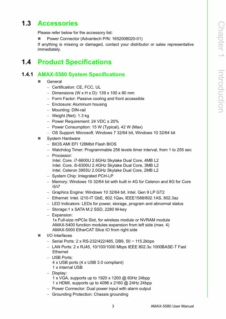
1.3 Accessories Please refer below for the accessory list: Power Connector (Advantech P/N: 1652008020-01) If anything is missing or damaged, contact your distributor or sales representativeimmediately.
1.4 Product Specifications1.4.1 AMAX-5580 System Specifications
General– Certification: CE, FCC, UL– Dimensions (W x H x D): 139 x 100 x 80 mm– Form Factor: Passive cooling and front accessible– Enclosure: Aluminum housing– Mounting: DIN-rail– Weight (Net): 1.3 kg– Power Requirement: 24 VDC ± 20%– Power Consumption: 15 W (Typical), 42 W (Max)– OS Support: Microsoft. Windows 7 32/64 bit, Windows 10 32/64 bit
System Hardware– BIOS AMI EFI 128Mbit Flash BIOS– Watchdog Timer: Programmable 256 levels timer interval, from 1 to 255 sec– Processor:
Intel. Core. i7-6600U 2.6GHz Skylake Dual Core, 4MB L2Intel. Core. i5-6300U 2.4GHz Skylake Dual Core, 3MB L2Intel. Celeron 3955U 2.0GHz Skylake Dual Core, 2MB L2
– System Chip: Integrated PCH-LP– Memory: Windows 10 32/64 bit with built in 4G for Celeron and 8G for Core
i5/i7– Graphics Engine: Windows 10 32/64 bit. Intel. Gen 9 LP GT2– Ethernet: Intel. i210-IT GbE, 802.1Qav, IEEE1588/802.1AS, 802.3az– LED Indicators: LEDs for power, storage, program and abnormal status– Storage:1 x SATA M.2 SSD, 2280 M-key– Expansion:
1x Full-size mPCIe Slot, for wireless module or NVRAM moduleAMAX-5400 function modules expansion from left side (max. 4)AMAX-5000 EtherCAT Slice IO from right side
I/O Interfaces– Serial Ports: 2 x RS-232/422/485, DB9, 50 ~ 115.2kbps– LAN Ports: 2 x RJ45, 10/100/1000 Mbps IEEE 802.3u 1000BASE-T Fast
Ethernet – USB Ports:
4 x USB ports (4 x USB 3.0 compliant)1 x internal USB
– Display:1 x VGA, supports up to 1920 x 1200 @ 60Hz 24bpp1 x HDMI, supports up to 4096 x 2160 @ 24Hz 24bpp
– Power Connector: Dual power input with alarm output– Grounding Protection: Chassis grounding

AMAX-5580 User Manual 4
Environment– Operating Temperature: -10 ~ 60°C (-4 ~ 140°F) @ 5 ~ 85% RH with 0.7m/s
airflow– Storage Temperature: -40 ~ 85°C (-40 ~ 185°F)– Relative Humidity: 10 ~ 95% RH @ 40°C, non-condensing– Shock Protection: Operating, IEC 60068-2-27, 10G, half sine, 11 ms– Vibration Protection: Operating, IEC 60068-2-64, 1 Grms, random, 5 ~ 500
Hz, 1hr/axis (M.2)
Chapter 22 AMAX-5000 System Overview
AMAX-5580 User Manual 6
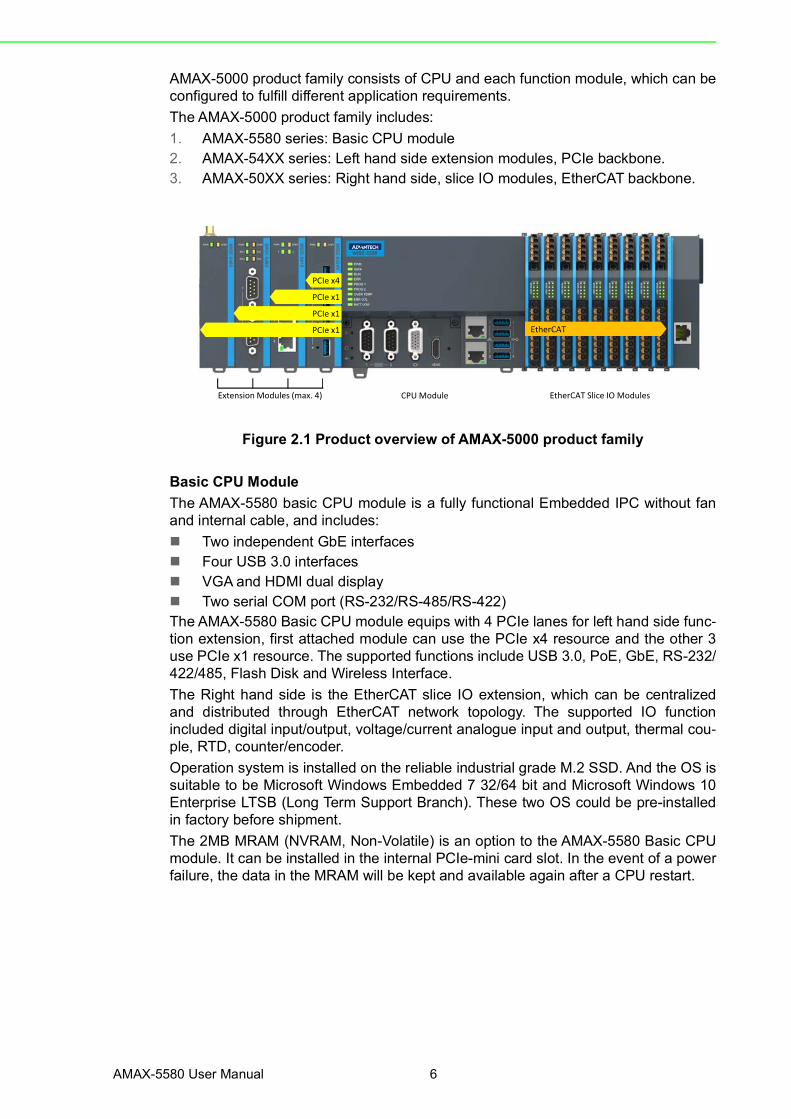
AMAX-5000 product family consists of CPU and each function module, which can beconfigured to fulfill different application requirements.The AMAX-5000 product family includes:1. AMAX-5580 series: Basic CPU module2. AMAX-54XX series: Left hand side extension modules, PCIe backbone.3. AMAX-50XX series: Right hand side, slice IO modules, EtherCAT backbone.
Figure 2.1 Product overview of AMAX-5000 product family
Basic CPU ModuleThe AMAX-5580 basic CPU module is a fully functional Embedded IPC without fanand internal cable, and includes: Two independent GbE interfaces Four USB 3.0 interfaces VGA and HDMI dual display Two serial COM port (RS-232/RS-485/RS-422)The AMAX-5580 Basic CPU module equips with 4 PCIe lanes for left hand side func-tion extension, first attached module can use the PCIe x4 resource and the other 3use PCIe x1 resource. The supported functions include USB 3.0, PoE, GbE, RS-232/422/485, Flash Disk and Wireless Interface. The Right hand side is the EtherCAT slice IO extension, which can be centralizedand distributed through EtherCAT network topology. The supported IO functionincluded digital input/output, voltage/current analogue input and output, thermal cou-ple, RTD, counter/encoder.Operation system is installed on the reliable industrial grade M.2 SSD. And the OS issuitable to be Microsoft Windows Embedded 7 32/64 bit and Microsoft Windows 10Enterprise LTSB (Long Term Support Branch). These two OS could be pre-installedin factory before shipment.The 2MB MRAM (NVRAM, Non-Volatile) is an option to the AMAX-5580 Basic CPUmodule. It can be installed in the internal PCIe-mini card slot. In the event of a powerfailure, the data in the MRAM will be kept and available again after a CPU restart.
Extension Modules (max. 4) CPU Module EtherCAT Slice IO Modules
PCIe x1
PCIe x4
PCIe x1
PCIe x1 EtherCAT
7 AMAX-5580 User Manual
Chapter 2
AMAX-5000 System
Overview
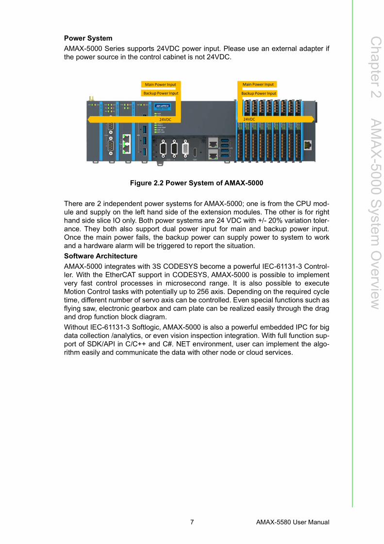
Power SystemAMAX-5000 Series supports 24VDC power input. Please use an external adapter ifthe power source in the control cabinet is not 24VDC.
Figure 2.2 Power System of AMAX-5000
There are 2 independent power systems for AMAX-5000; one is from the CPU mod-ule and supply on the left hand side of the extension modules. The other is for righthand side slice IO only. Both power systems are 24 VDC with +/- 20% variation toler-ance. They both also support dual power input for main and backup power input.Once the main power fails, the backup power can supply power to system to workand a hardware alarm will be triggered to report the situation.Software ArchitectureAMAX-5000 integrates with 3S CODESYS become a powerful IEC-61131-3 Control-ler. With the EtherCAT support in CODESYS, AMAX-5000 is possible to implementvery fast control processes in microsecond range. It is also possible to executeMotion Control tasks with potentially up to 256 axis. Depending on the required cycletime, different number of servo axis can be controlled. Even special functions such asflying saw, electronic gearbox and cam plate can be realized easily through the dragand drop function block diagram.Without IEC-61131-3 Softlogic, AMAX-5000 is also a powerful embedded IPC for bigdata collection /analytics, or even vision inspection integration. With full function sup-port of SDK/API in C/C++ and C#. NET environment, user can implement the algo-rithm easily and communicate the data with other node or cloud services.
24VDC
Main Power Input
Backup Power Input Backup Power Input
Main Power Input
24VDC

AMAX-5580 User Manual 8
2.1 Configuration of CPU Module, AMAX-5580
Figure 2.3 Front View of AMAX-5580
Table 2.1: Legend of configuration of AMAX-5580 CPU moduleNo. Component Description
1 EtherCAT Slice Connection Connection for EtherCAT Slice IO extension modules.
2 USB Interface Interfaces for peripherals such as mouse, keyboard or USB memory.
3 RJ45 Ethernet Interface For connecting to local networks, internet or EtherCAT.
4 HDMI Interface Digital interface for a monitor or panel with audio output
5 VGA Interface Analogue interface for a monitor or panel
6 & 7 DB9 Interface Interface for serial communication (RS-232/422/485 selectable in BIOS)
8 Shielding Ground Connection Screw to fix the shielding ground connection
9 Reset Button Hidden button for PC hardware reset func-tion
10 Power Button Hidden button for PC power function11 Multi-function Connection Connection for PCIe extension modules12 Diagnostic LEDs Diagnostic LEDs for CPU module
13 Power Input Wiring Terminal 7-pin terminal for dual 24VDC power input wiring and alarm output
A & B Screws Screws to open the front cover for internal configuration
9 AMAX-5580 User Manual
Chapter 2
AMAX-5000 System
Overview
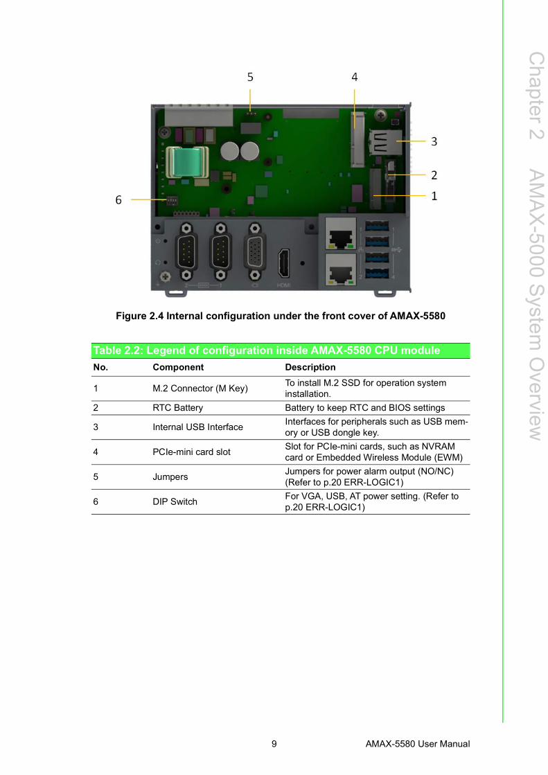
Figure 2.4 Internal configuration under the front cover of AMAX-5580
Table 2.2: Legend of configuration inside AMAX-5580 CPU moduleNo. Component Description
1 M.2 Connector (M Key) To install M.2 SSD for operation system installation.
2 RTC Battery Battery to keep RTC and BIOS settings
3 Internal USB Interface Interfaces for peripherals such as USB mem-ory or USB dongle key.
4 PCIe-mini card slot Slot for PCIe-mini cards, such as NVRAM card or Embedded Wireless Module (EWM)
5 Jumpers Jumpers for power alarm output (NO/NC)(Refer to p.20 ERR-LOGIC1)
6 DIP Switch For VGA, USB, AT power setting. (Refer to p.20 ERR-LOGIC1)

AMAX-5580 User Manual 10
2.2 Module Overview2.2.1 AMAX-54XX PCIe Expansion Module
AMAX-5580 provide PCIe extension interface from the left-hand side, and there arefollowing modules available:
Table 2.3: Table 3: List of AMAX-54XX series extension modulesNo. Model Front View Description
1 AMAX-5400E
Wireless Expansion Module-PCIe-mini Card Slot (full-size) inside for Advantech EWM module installation.-With nano-SIM card slot for telecom ser-vice.
2 AMAX-5424V
USB 3.0 Interface Module-4x USB 3.0 with full bandwidth*
*Full USB 3.0 bandwidth only work in the first slot which is with PCIex4 resource.
3 AMAX-5490
Serial Communication Module-2x RS-232/422/485 with DB9 connector-2500VDC isolation
4 AMAX-5410
GigE Communication Module-2x GigE with RJ45-Speed 10/100/1000Mbps-With Intel i350-AM2 NIC
5 AMAX-5410P
PoE Communication Module-2x GigE with RJ45-Speed 10/100/1000Mbps-With Intel i350-AM2 NIC-PoE power 48VDC with max 20W per module
Note! EtherCAT supports up to 65535 slave devices in one network. However more devices would need longer cycle time to have all real-time data back to master.
11 AMAX-5580 User Manual
Chapter 2
AMAX-5000 System
Overview
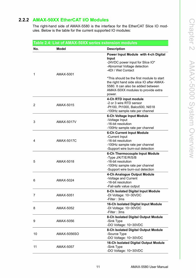
2.2.2 AMAX-50XX EtherCAT I/O ModulesThe right-hand side of AMAX-5580 is the interface for the EtherCAT Slice IO mod-ules. Below is the table for the current supported IO modules:
Table 2.4: List of AMAX-50XX series extension modulesNo. Model Description
1 AMAX-5001
Power Input Module with 4-ch Digital Input-24VDC power input for Slice IO*-Abnormal Voltage detection-4DI / Wet Contact
*This should be the first module to start the right hand side slice IO after AMAX-5580. It can also be added between AMAX-50XX modules to provide extra power.
2 AMAX-5015
4-Ch RTD input module-2 or 3 wire RTD sensor-Pt100, Pt1000, Balco500, Ni518-100Hz sample rate per channel
3 AMAX-5017V
6-Ch Voltage Input Module-Voltage Input-16-bit resolution-100Hz sample rate per channel
4 AMAX-5017C
6-Ch Current Input Module-Current Input-16-bit resolution-100Hz sample rate per channel-Support wire burn-out detection
5 AMAX-5018
6-Ch Thermocouple Input Module-Type J/K/T/E/R/S/B-16-bit resolution-100Hz sample rate per channel-Support wire burn-out detection
6 AMAX-5024
4-Ch Analogue Output Module-Voltage and Current-16-bit resolution-Fail-safe value output
7 AMAX-50518-Ch Isolated Digital Input Module-DI Voltage: 10~30VDC-Filter : 3ms
8 AMAX-505216-Ch Isolated Digital Input Module-DI Voltage: 10~30VDC-Filter : 3ms
9 AMAX-50568-Ch Isolated Digital Output Module-Sink Type-DO Voltage: 10~30VDC
10 AMAX-5056SO8-Ch Isolated Digital Output Module-Source Type-DO Voltage: 10~30VDC
11 AMAX-505716-Ch Isolated Digital Output Module-Sink Type-DO Voltage: 10~30VDC
AMAX-5580 User Manual 12
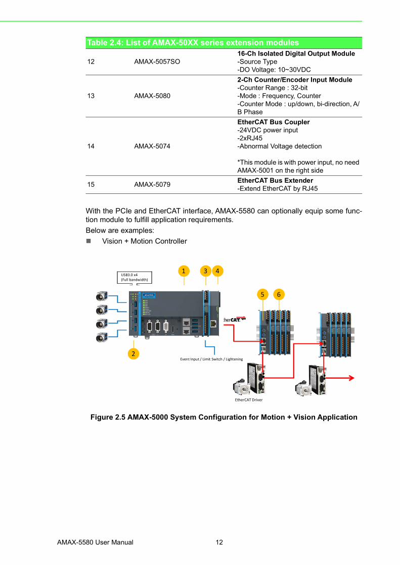
With the PCIe and EtherCAT interface, AMAX-5580 can optionally equip some func-tion module to fulfill application requirements.Below are examples: Vision + Motion Controller
Figure 2.5 AMAX-5000 System Configuration for Motion + Vision Application
12 AMAX-5057SO16-Ch Isolated Digital Output Module-Source Type-DO Voltage: 10~30VDC
13 AMAX-5080
2-Ch Counter/Encoder Input Module-Counter Range : 32-bit-Mode : Frequency, Counter-Counter Mode : up/down, bi-direction, A/B Phase
14 AMAX-5074
EtherCAT Bus Coupler-24VDC power input-2xRJ45-Abnormal Voltage detection
*This module is with power input, no need AMAX-5001 on the right side
15 AMAX-5079 EtherCAT Bus Extender-Extend EtherCAT by RJ45
Table 2.4: List of AMAX-50XX series extension modules
USB3.0 x4(Full bandwidth)
Event Input / Limit Switch / Lightening
EtherCAT Driver
1
2
3 4
5 6

13 AMAX-5580 User Manual
Chapter 2
AMAX-5000 System
Overview
Data Concentrator
Figure 2.6 AMAX-5000 System Configuration for Big Data Edge Concentrator
Table 2.5: AMAX-5000 System Configuration for Motion + Vision ApplicationNo. Part Number Description1 AMAX-5580 CPU Module to integrate Motion and Vision application2 AMAX-5424V USB 3.0 x4 expansion for camera2a AMAX-5410 (option) GibE x2 expansion for camera2b AMAX-5410P (option) PoE x2 expansion for camera
3 AMAX-5001 24VDC Power input module for AMAX-5000 Slice IO, include 4DI
4 AMAX-5079 Extend EtherCAT to next station5 AMAX-5074 EtherCAT bus coupler6 AMAX-50XX AMAX-5000 Slice IO to fulfill the IO requirement of the station
No. Part Number Description1 AMAX-5580 CPU Module to handle big data applications2 AMAX-5400 Wireless expansion option for Wi-Fi/ 3G/ LTE3 AMAX-5490 2x Isolation COM port expansion, RS-232/422/4854 AMAX-5001 24VDC Power input module for AMAX-5000 slice IO, include 4DI5 AMAX-50XX AMAX-5000 Slice IO to fulfill the IO requirement of the station6 AMAX-5079 Extend EtherCAT to next station7 AMAX-5074 EtherCAT bus coupler8 AMAX-50XX AMAX-5000 Slice IO to fulfill the IO requirement of the station
Wireless Option
1 5 6
7 8
3
4
2RTDThermocouple
AMAX-5580 User Manual 14
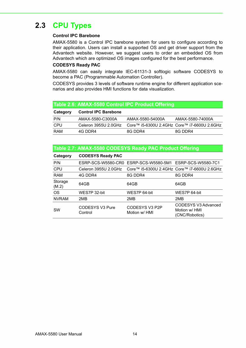
2.3 CPU TypesControl IPC BareboneAMAX-5580 is a Control IPC barebone system for users to configure according totheir application. Users can install a supported OS and get driver support from theAdvantech website. However, we suggest users to order an embedded OS fromAdvantech which are optimized OS images configured for the best performance.CODESYS Ready PACAMAX-5580 can easily integrate IEC-61131-3 softlogic software CODESYS tobecome a PAC (Programmable Automation Controller).CODESYS provides 3 levels of software runtime engine for different application sce-narios and also provides HMI functions for data visualization.
Table 2.6: AMAX-5580 Control IPC Product OfferingCategory Control IPC BareboneP/N AMAX-5580-C3000A AMAX-5580-54000A AMAX-5580-74000ACPU Celeron 3955U 2.0GHz Core™ i5-6300U 2.4GHz Core™ i7-6600U 2.6GHzRAM 4G DDR4 8G DDR4 8G DDR4
Table 2.7: AMAX-5580 CODESYS Ready PAC Product OfferingCategory CODESYS Ready PACP/N ESRP-SCS-W5580-CR0 ESRP-SCS-W5580-5M1 ESRP-SCS-W5580-7C1CPU Celeron 3955U 2.0GHz Core™ i5-6300U 2.4GHz Core™ i7-6600U 2.6GHzRAM 4G DDR4 8G DDR4 8G DDR4Storage (M.2) 64GB 64GB 64GB
OS WES7P 32-bit WES7P 64-bit WES7P 64-bitNVRAM 2MB 2MB 2MB
SW CODESYS V3 Pure Control
CODESYS V3 P2P Motion w/ HMI
CODESYS V3 Advanced Motion w/ HMI(CNC/Robotics)

15 AMAX-5580 User Manual
Chapter 2
AMAX-5000 System
Overview
2.4 CPU architecture
Figure 2.7 System Architecture of AMAX-5580
Note! LAN2 and PCIe-mini Card Shared Resource
Inteli210AT
PCIex1 EtherCAT
Slice IODDI Port 1
DDI Port 2
HDMIVGA
PCIe Switch
4x USB 3.0
Super IO
LPC
COM1/2
SATA (P2)
M.2 (Key M)
LAN USB 3.0
Dual Memory Bus
2x SATA
1x PCIex4 + 3x PCIe x1
4x USB 2.0
Golden Finger(High Speed Slot )
USB 2.0
Internal USB 2.0
PCIe‐mini Card Slot (NVRAM installed)
Intel Skylake U CPU :Celeron 3955UCore i5 6300UCore i7 6600U
DDR4 Memory Bank
DDR4 Memory Bank
Inteli210AT
USB 2.0
PCIex1
PCIex1
Inteli210AT

AMAX-5580 User Manual 16

Chapter 33 Initial Setup

AMAX-5580 User Manual 18
3.1 Selecting the Right Power Supply UnitThe AMAX-5580 needs an external 24VDC power input from the screw terminal onthe top. And this power input will supply power to the main CPU module (AMAX-5580) and left-hand-side PCIe expansion modules (AMAX-54XX).The pin definition isas below:
To keep the system working properly, the user has to calculate the system powerconsumption to select the proper power supply unit. The selected power supplyshould provide more power than the max power consumption of the system.For example:
We suggest adding a tolerance on the total power consumption and also consider thepower de-rating effect in your application environment. Below is a suggestion list ofverified power supply units:
Table 3.1: Pin Definition of Power Input TerminalNo Name Function1 FG Field Ground Connection2 V1+
Power Input 13 V1-4 V2+
Power Input 25 V2-6 RL+ Power Abnormal Relay Output (Normal Close/Open changeable)
* Refer to p.20 ERR-LOGIC17 RL-
Item Model Function Max Power Consumption1 AMAX-5580 Main CPU Module 42W2 AMAX-5424V 4x USB 15W3 AMAX-5490 2x Serial Port 2W
Sub-total 59W
Item Part Number Description1 PSD-A60W24 DIN Rail AC to DC 100-240V 60W 24V2 PSD-A120W24 DIN Rail AC to DC 100-240V 120W 24V3 96PSD-A240W24-MN DIN Rail AC to DC 100-240V 240W 24V

19 AMAX-5580 User Manual
Chapter 3
Initial Setup
The default power mode is AT mode, the system will boot as long as there is onevalid power input from 1 or 2. Please check below LED to make sure the system isproperly powered.
NOTE: Please do not assemble or disassemble the system while the PWR /STBYLED is on. Please make sure power is completely off and every LED is off beforechanging hardware.To enhance the system availability, AMAX-5580 provides dual power input functionsto support main power input and backup power input. If either power input encoun-ters trouble it will trigger the below alarms:1. The LED “ERR VOL” turns “On”2. The RL+ /RL- on the Power Input Terminal changes (Refer to p.20 ERR-LOG-
IC1)3. The system tag changes and can be accessed remotely.
3.2 System Configuration and InstallationPlease refer to section 1.1, table 2 to do the necessary configuration or maintenance.Please follow below step to open the front cover to do access the internal systemcomponents:Step1: Remove the 7-pin power input wiring terminal on the top of the deviceStep2: Remove the USB/HDMI fix kit from the front cover (Option)Step3: Remove 2 screws on the lower side of the front coverStep4: Move the cover upward slightly and move forward.User can do the following: Install the M.2 SSD storage
This is the SSD storage for the operating system, we suggest using industrial grade SSD to ensure system reliability. Please refer to the datasheet to check the parts which have been verified as working well with the system.After installing the SSD, please fix the SSD in the slots with the screws pro-vided.
Install the PCIe-mini card moduleUsers can install a PCIe-mini card module in the PCIe-mini card slot. For exam-ple:– NVRAM module: PCM-2300MR-AE
Provides non-volatile memory for the system. This function is usually neces-sary for running a softlogic system.
– Advantech EWM wireless moduleInclude Wi-Fi, 3G, LTE, GPS function available for optional expansion, there is one hole reserved for antenna SMA connector on the top cover.
– Other 3rd party PCIe-mini card modulesThis PCIe-mini card is with PCIex1 signal and USB2.0 signal, please check the signal compatibility and driver availability first.
After inserting the PCIe-mini card module, fix with the screws provided.
Model LED Status Definition
AMAX-5580 PWRGreen System Power OKOrange System Standby
AMAX-54XXPWR Green System Power OKSTBY Orange System Standby
AMAX-5580 User Manual 20
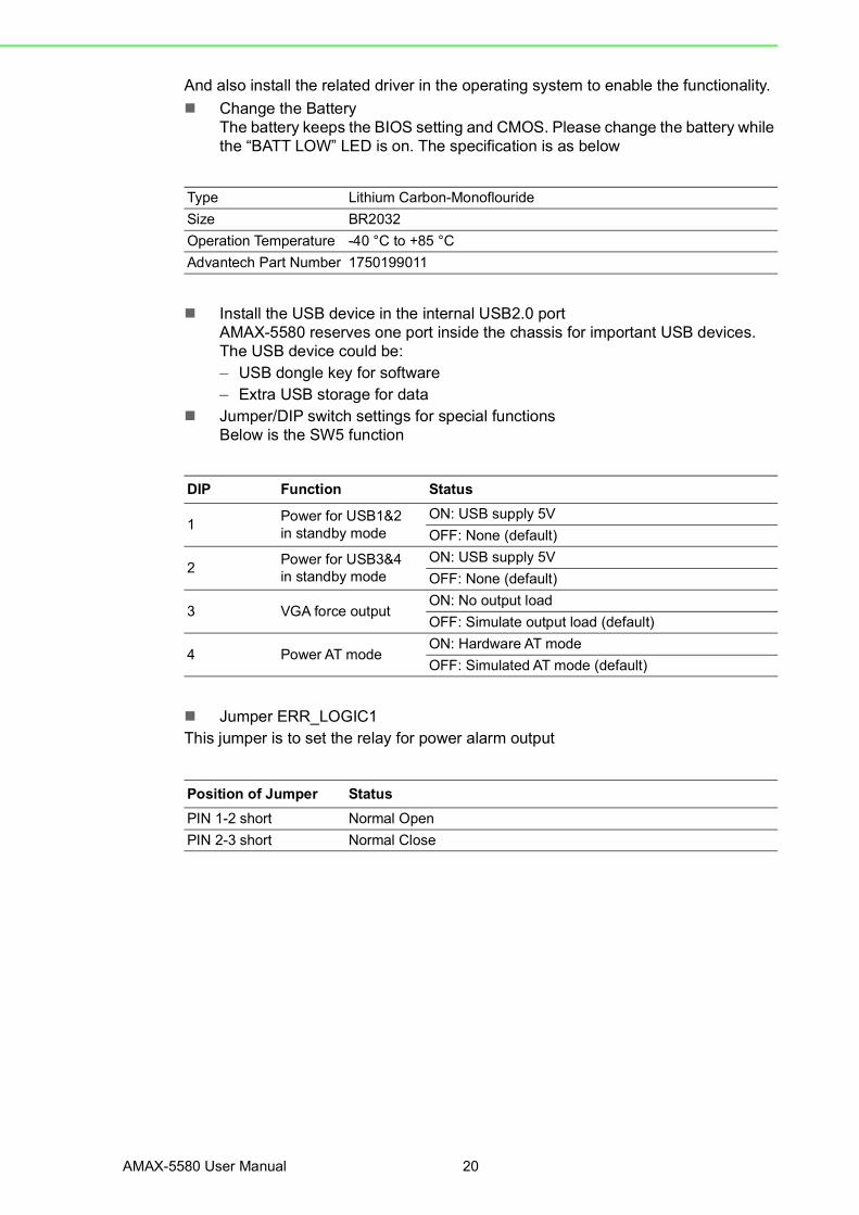
And also install the related driver in the operating system to enable the functionality. Change the Battery
The battery keeps the BIOS setting and CMOS. Please change the battery while the “BATT LOW” LED is on. The specification is as below
Install the USB device in the internal USB2.0 portAMAX-5580 reserves one port inside the chassis for important USB devices. The USB device could be:– USB dongle key for software– Extra USB storage for data
Jumper/DIP switch settings for special functionsBelow is the SW5 function
Jumper ERR_LOGIC1This jumper is to set the relay for power alarm output
Type Lithium Carbon-MonoflourideSize BR2032Operation Temperature -40 °C to +85 °CAdvantech Part Number 1750199011
DIP Function Status
1 Power for USB1&2 in standby mode
ON: USB supply 5VOFF: None (default)
2 Power for USB3&4in standby mode
ON: USB supply 5VOFF: None (default)
3 VGA force outputON: No output loadOFF: Simulate output load (default)
4 Power AT modeON: Hardware AT modeOFF: Simulated AT mode (default)
Position of Jumper StatusPIN 1-2 short Normal OpenPIN 2-3 short Normal Close

21 AMAX-5580 User Manual
Chapter 3
Initial Setup
3.3 Mounting3.3.1 Attaching the AMAX-54XX left-hand-side module (option)
Left-hand-side PCIe module should be assembled before mounting on the DIN-rail.Please follow steps below to install.Step1: Use the guide pin to direct the module in the right position.Step2: Push the golden finger into the slotStep3: Affix the screws to make sure the combination is tight. Step4: Follow the same steps to stack the 2nd and next AMAX-54XX module
3.3.2 Permissible installation positionsNote: The CPU module may overheat if the installation position is incorrect or mini-mum distances are not adhered to.
AMAX-5580 uses a passive cooling system and does not need a correct mountingposition to ensure optimum heat dissipation.Note the below requirements for the control cabinet:1. Please make sure the temperature of the control cabinet is within the operating
temperature of AMAX-5580, which is -10~60 °C2. Please adhere to the minimum clearance of 50 mm above and below the CPU
module, in order to ensure proper ventilation3. Select a suitable control cabinet enclosure to ensure the heat can be dissipated
from the control cabinet
Figure 3.1 Mounting position for AMAX-5580
Toward Ground
5cm
5cm

AMAX-5580 User Manual 22
3.3.3 Attaching on the DIN-railPlease follow the below steps to secure AMAX-5580 on the DIN-rail:Step1: Unlock the latches at the bottom of AMAX-5580 and AMAX-54XXStep2: Place the AMAX-5580 on the DIN-rail, hang the device on the top side of theDIN-rail then push the lower side of the device onto the DIN-rail.Step3: Lock the latches
3.3.4 Install the AMAX-50XX right-hand-side modulesNote: The AMAX-50XX on the right-hand-side has independent power system.AMAX-5001, smart power input terminal should be the first module to supply thepower to the right side AMAX-50XX modules.Please follow below steps to slice in the module one by one:Step1: Unlock the latched at the bottom of AMAX-50XXStep2: Remove the protection cover on the right-side of AMAX-5580, and slice in themodule on the side of the AMAX-5580Step3: Touch the orange part on the lower side to release the latch to lock the moduleon the DIN-rail
Figure 3.2 AMAX-5000 installed in control box
3.4 BIOS Setup3.4.1 How to enter the BIOS?
First, plug-in the 24VDC input power to boot the AMAX-5580 or reboot it if it is run-ning. Second, press the “Delete” key while the AMAX-5580 is performing the power-on self-test (POST). If you can hear the “beep” sound from your AMAX-5580 control-ler, you are successfully accessing the BIOS.
Power Supply
Power Supply Remote I/O
Controller

23 AMAX-5580 User Manual
Chapter 3
Initial Setup
3.4.2 BIOS configurationWhen you enter the BIOS, the “Main” tab list overall information to the AMAX-5580controller; you will see BIOS information and Processor Information on this page.
Figure 3.3 BIOS and processor information
3.4.3 Hardware MonitorThe “Hardware Monitor” option under “Advanced” tab shows all hardware monitorsensors real-time values.
Figure 3.4 Configuration list under Advanced tab in BIOS

AMAX-5580 User Manual 24
Figure 3.5 The Hardware Sensors Value showed in BIOS
3.4.3.1 CPU Overheating Temperature and CPU Shutdown TemperatureThere are many factors that could lead to CPU temperature overheating, such asimproper system installation, high ambient temperatures or poor ventilation.You may set the “CPU Over Temperature” value in BIOS configuration and the LEDindicator (OVER TEMP) on the front panel will be turned on when the CPU tempera-ture becomes abnormal. In order to protect your system from overheating; you couldalso set the “CPU Shutdown Temperature” value. If the CPU overheats, the systemwill shut down automatically.
Figure 3.6 The CPU shutdown temperature and overheating temperature configuration in BIOS
25 AMAX-5580 User Manual
Chapter 3
Initial Setup
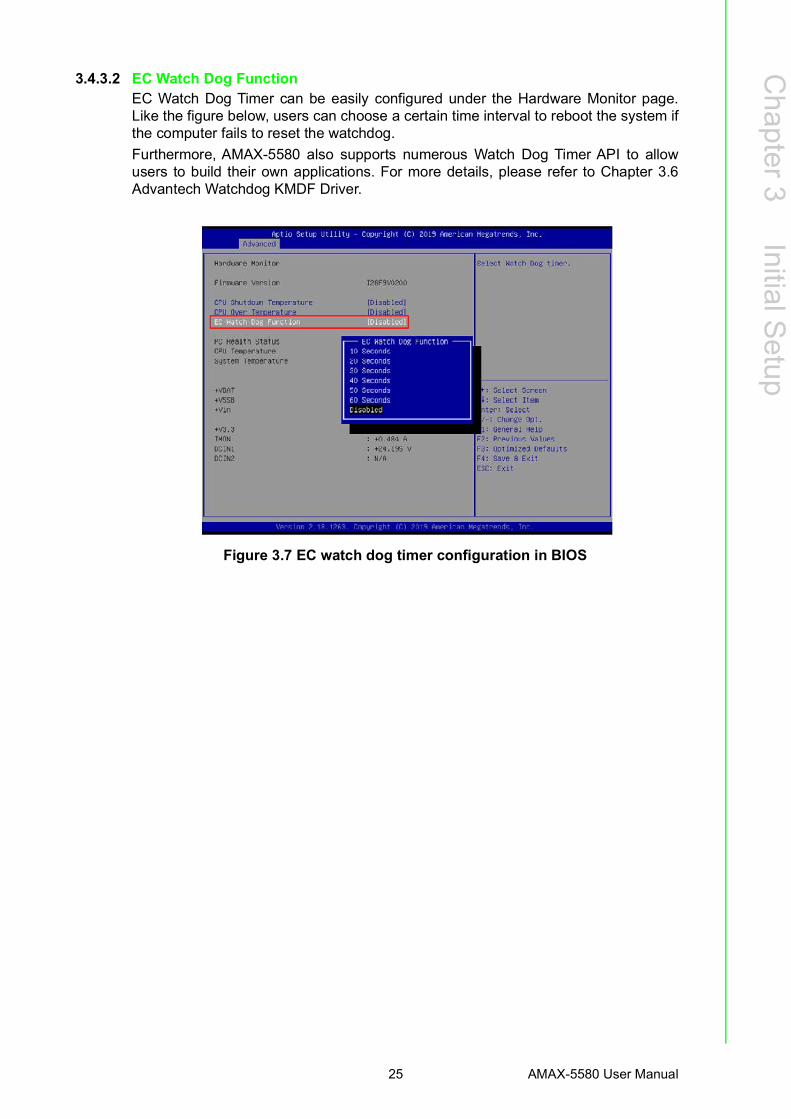
3.4.3.2 EC Watch Dog FunctionEC Watch Dog Timer can be easily configured under the Hardware Monitor page.Like the figure below, users can choose a certain time interval to reboot the system ifthe computer fails to reset the watchdog.Furthermore, AMAX-5580 also supports numerous Watch Dog Timer API to allowusers to build their own applications. For more details, please refer to Chapter 3.6Advantech Watchdog KMDF Driver.
Figure 3.7 EC watch dog timer configuration in BIOS

AMAX-5580 User Manual 26
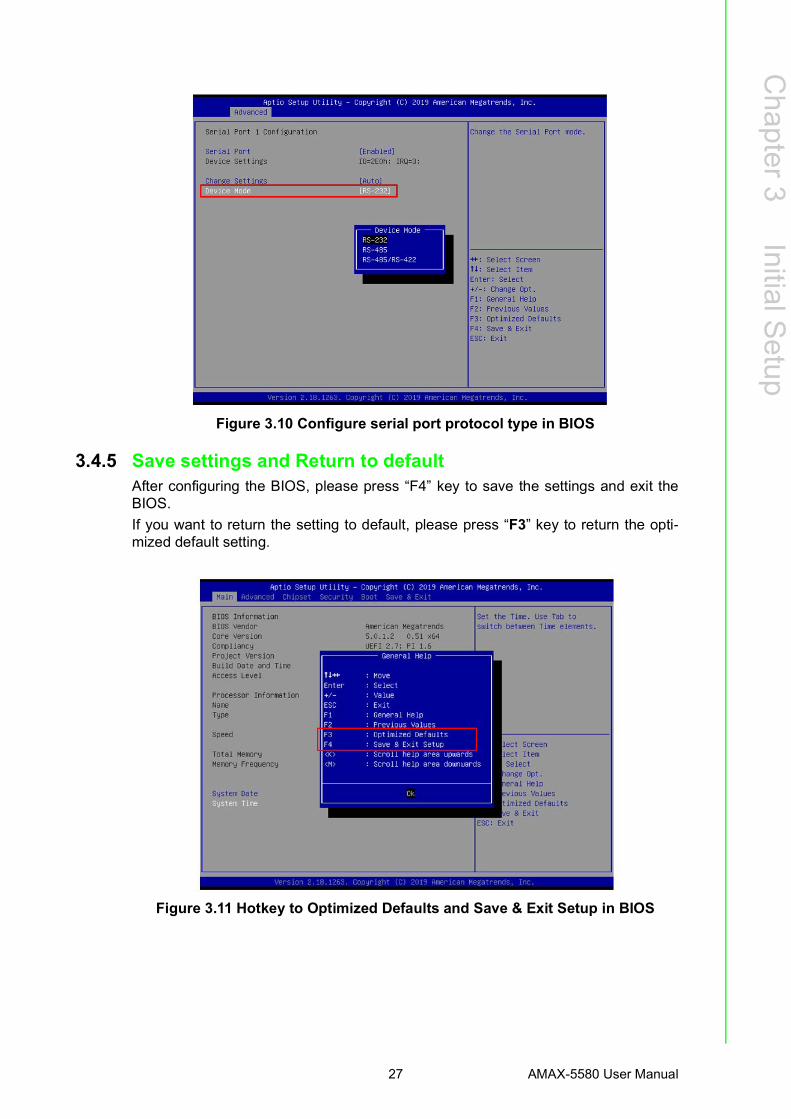
3.4.4 Serial port configurationIn order to configure the two DB9 serial ports at the front panel into the same protocolyou're connecting, you may enter the “Advanced” tab and select “Serial Port Config-uration” to enable the serial port and select the protocol type.
Figure 3.8 Serial port configuration in BIOS
Figure 3.9 Enabling serial port in BIOS
27 AMAX-5580 User Manual
Chapter 3
Initial Setup
Figure 3.10 Configure serial port protocol type in BIOS
3.4.5 Save settings and Return to defaultAfter configuring the BIOS, please press “F4” key to save the settings and exit theBIOS. If you want to return the setting to default, please press “F3” key to return the opti-mized default setting.
Figure 3.11 Hotkey to Optimized Defaults and Save & Exit Setup in BIOS

AMAX-5580 User Manual 28
Chapter 44 Software Tools
AMAX-5580 User Manual 30
AMAX-5580 controller also has useful utilities and drivers to help you monitor yourdevice or build your own applications for advanced uses. All the utilities and driversare bundled in the OS image which has already been pre-installed in your AMAX-5580.
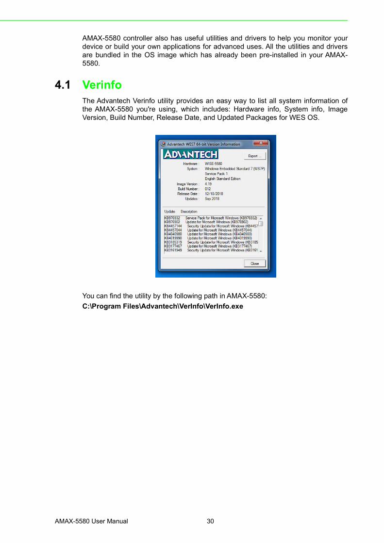
4.1 VerinfoThe Advantech Verinfo utility provides an easy way to list all system information ofthe AMAX-5580 you're using, which includes: Hardware info, System info, ImageVersion, Build Number, Release Date, and Updated Packages for WES OS.
You can find the utility by the following path in AMAX-5580: C:\Program Files\Advantech\VerInfo\VerInfo.exe
31 AMAX-5580 User Manual
Chapter 4
Software Tools
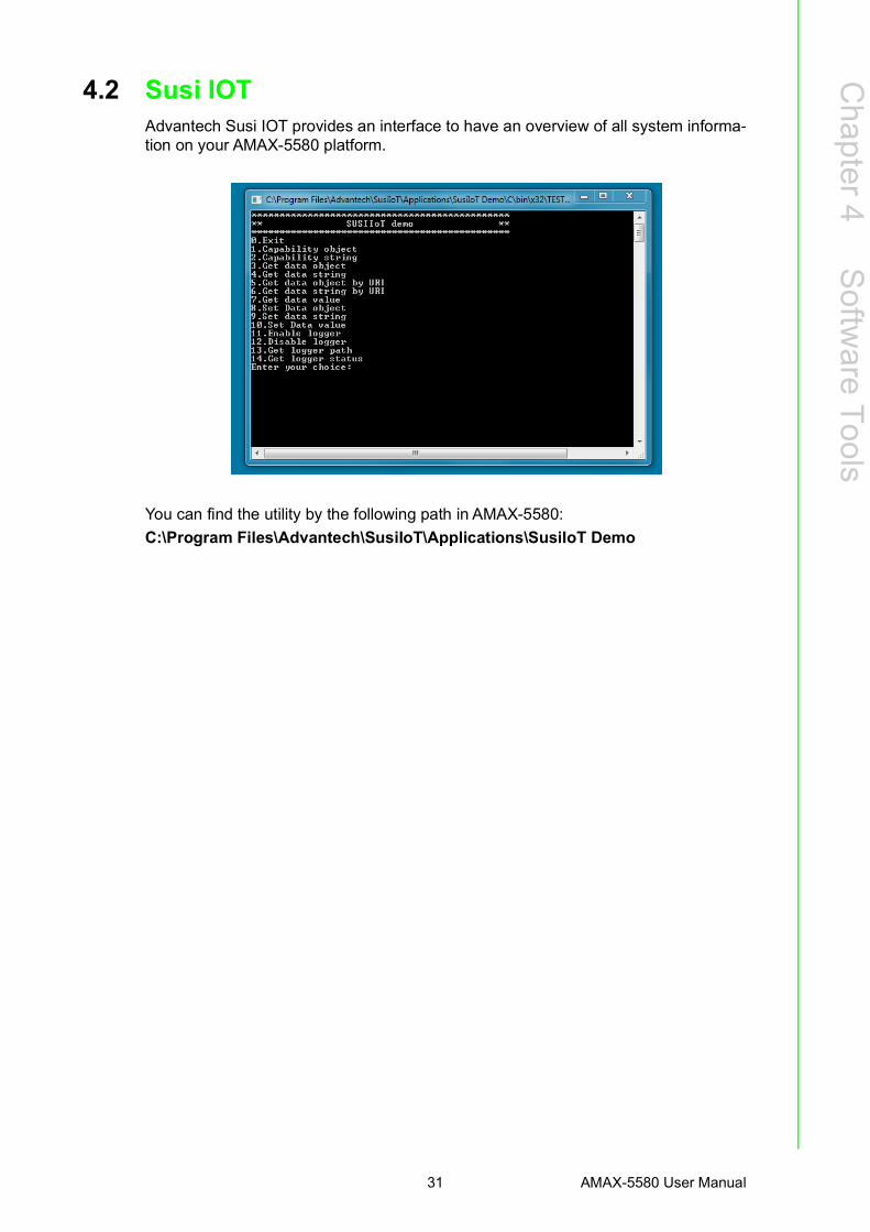
4.2 Susi IOTAdvantech Susi IOT provides an interface to have an overview of all system informa-tion on your AMAX-5580 platform.
You can find the utility by the following path in AMAX-5580: C:\Program Files\Advantech\SusiIoT\Applications\SusiIoT Demo
AMAX-5580 User Manual 32
4.3 EAPIEmbedded API (EAPI) follows PICMG EAPI to specify functions for industrial applica-tion and to provide a common programming interface. The target is to avoid softwaremodifications when changing device modules. EAPI will cover all interfaces in thedevice to unify the software control:You can find developer guide and sample codes by the following path in AMAX-5580:C:\Program Files\Advantech\PlatFormSDK
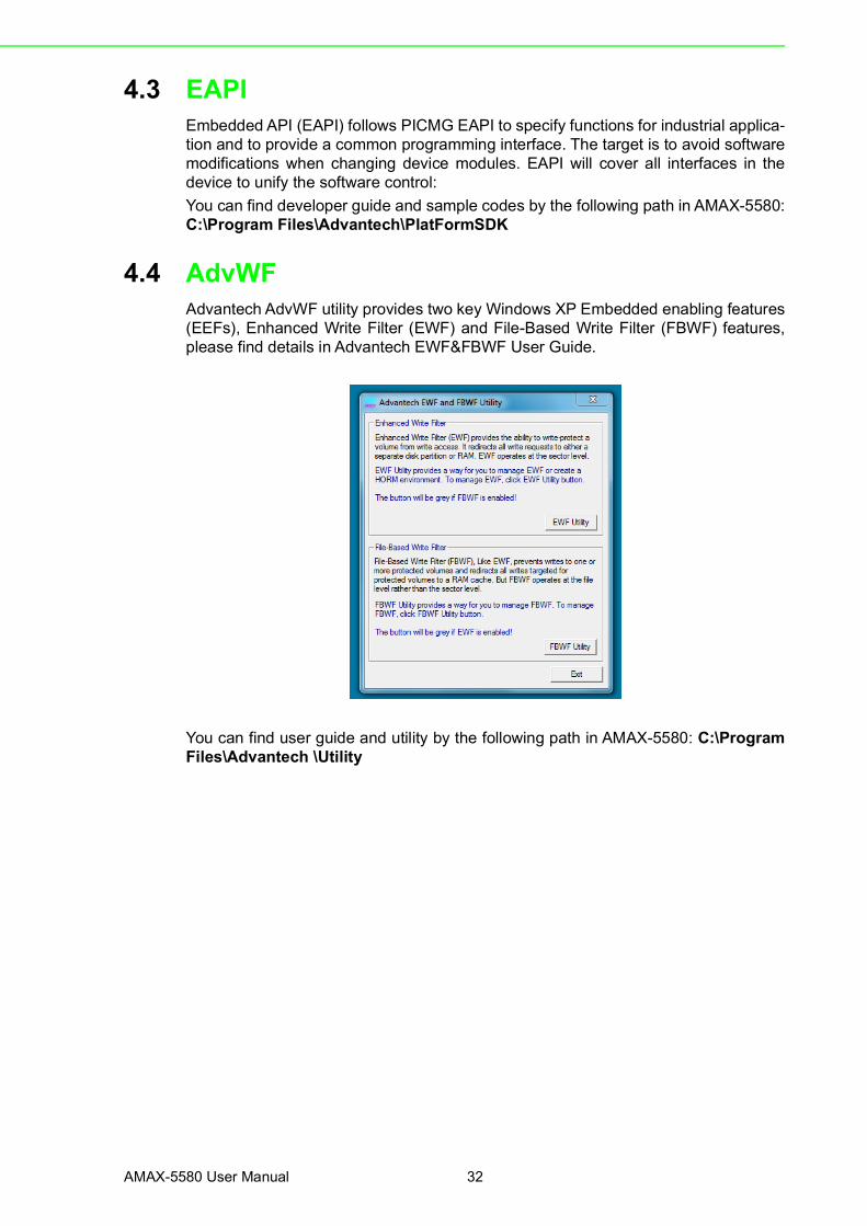
4.4 AdvWFAdvantech AdvWF utility provides two key Windows XP Embedded enabling features(EEFs), Enhanced Write Filter (EWF) and File-Based Write Filter (FBWF) features,please find details in Advantech EWF&FBWF User Guide.
You can find user guide and utility by the following path in AMAX-5580: C:\ProgramFiles\Advantech \Utility

33 AMAX-5580 User Manual
Chapter 4
Software Tools
4.5 Advantech LmsensorThe Advantech Lmsensor device driver provides functions to maximize the hard-ware's performance.The driver allows you to easily perform versatile Lmsensor operations in programsdeveloped with tools like Microsoft Visual C++, Embedded Visual C++, and other pro-gramming languages in different Windows system platforms. This driver also pro-vides sample applications so you can modify sample code to meet your needs.
You can find examples and the user manual by the following the path in AMAX-5580:C:\ Program Files (x86)\Advantech\Lmsensor

AMAX-5580 User Manual 34
4.6 Advantech Watchdog KMDF DriverAdvantech Watchdog KMDF Driver contains a set of functions and related structuresthat can be used in various application programs for interfacing with KMDF Drivers.The APIs support Microsoft Visual C++, Microsoft Visual Basic, and Microsoft C#development environments. You can directly write applications with windows API.Examples of VC, VC.NET, VB.NET, and C#.NET are supplied in the package, provid-ing a reference for you to develop applications. When development work is com-pleted, you can use test tools to verify if functions of your application are workingcorrect.
You can find examples and user manual by the following path in AMAX-5580: C:\Program Files (x86)\Advantech\Watchdog
Chapter 55 PCIe Expansion Module

AMAX-5580 User Manual 36
5.1 AMAX-5424V 4-port USB3.0 Vision Frame Grabber ModuleThe AMAX-5424V provides four extra USB3.0 ports to the AMAX-5580 controller.
Figure 5.1 AMAX-5424V Module
5.1.1 AMAX-5424V Specification
General:
USB Port:
Certification CE, FCC class AConnector 4 x USB 3.0 Type AEnclosure Aluminum housingPower Consumption 2.5W@24VDCBus Interface PCIe x4 (1st slot on the left side of AMAX-5580)LED Indicator PWR, Standby
Host Bus 4-lane Gen 2.0 PCIe interface, compliant with PCI Express Base Specification, Revision 2.0
ControllerHost Controller - Fresco FL1100Compliant with USB 3.0 Specification and Intel® xHCI Specifica-tion, Revision 1.0
Max. current 1500 mA maximum per port
Data Transfer Rate
Super Speed (5.0 Gbps); High Speed (480.0 Mbps);Full Speed (12.0 Mbps);Low Speed (1.5 Mbps)

37 AMAX-5580 User Manual
Chapter 5
PCIe Expansion M
odule
Protection:
Environment:
5.1.2 LED Indicator
Figure 5.2 AMAX-5424V Module LED Indicator
ESD Protection 8KV (air), 4KV (contact)Isolation Protection 2,500 VDC (between USB port and backplane)
Operation Temperature -10~60°C (vertical mounted)Storage Temperature -40~85°CRelative Humidity 5~95% (non-condense)
LED Color Indication BehaviorPWR Green ON Controller Power on
STBY Yellow ON Controller StandbyConnected to DC power
AMAX-5580 User Manual 38
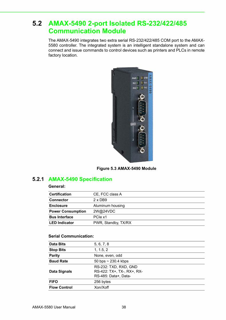
5.2 AMAX-5490 2-port Isolated RS-232/422/485 Communication ModuleThe AMAX-5490 integrates two extra serial RS-232/422/485 COM port to the AMAX-5580 controller. The integrated system is an intelligent standalone system and canconnect and issue commands to control devices such as printers and PLCs in remotefactory location.
Figure 5.3 AMAX-5490 Module
5.2.1 AMAX-5490 SpecificationGeneral:
Serial Communication:
Certification CE, FCC class AConnector 2 x DB9Enclosure Aluminum housingPower Consumption 2W@24VDCBus Interface PCIe x1LED Indicator PWR, Standby, TX/RX
Data Bits 5, 6, 7, 8Stop Bits 1, 1.5, 2Parity None, even, oddBaud Rate 50 bps ~ 230.4 kbps
Data SignalsRS-232: TXD, RXD, GNDRS-422: TX+, TX-, RX+, RX-RS-485: Data+, Data-
FIFO 256 bytesFlow Control Xon/Xoff
39 AMAX-5580 User Manual
Chapter 5
PCIe Expansion M
odule
Protection:
Environment:
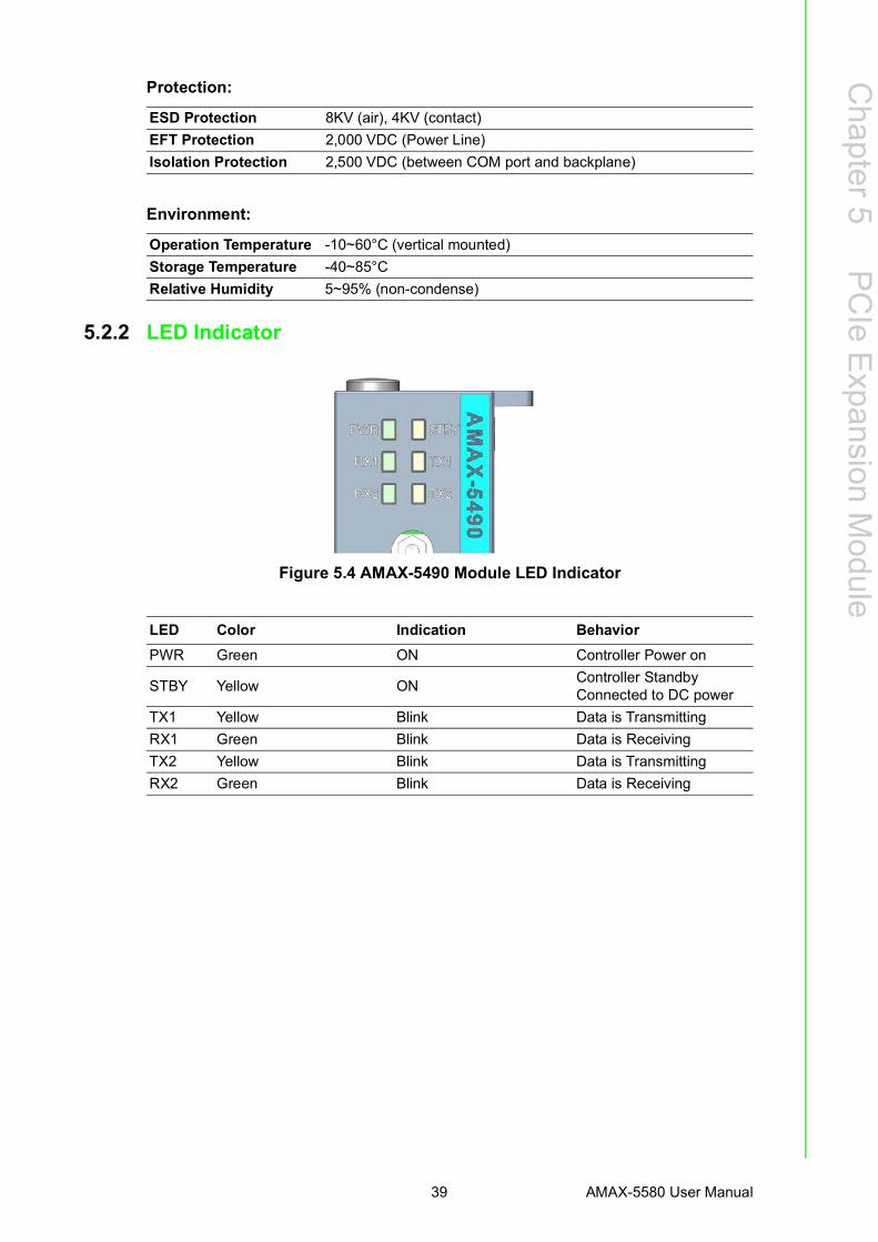
5.2.2 LED Indicator
Figure 5.4 AMAX-5490 Module LED Indicator
ESD Protection 8KV (air), 4KV (contact)EFT Protection 2,000 VDC (Power Line)Isolation Protection 2,500 VDC (between COM port and backplane)
Operation Temperature -10~60°C (vertical mounted)Storage Temperature -40~85°CRelative Humidity 5~95% (non-condense)
LED Color Indication BehaviorPWR Green ON Controller Power on
STBY Yellow ON Controller StandbyConnected to DC power
TX1 Yellow Blink Data is TransmittingRX1 Green Blink Data is ReceivingTX2 Yellow Blink Data is TransmittingRX2 Green Blink Data is Receiving
AMAX-5580 User Manual 40
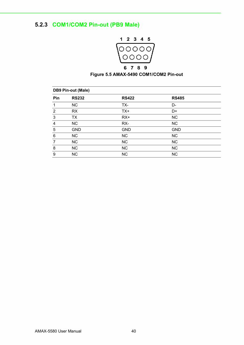
5.2.3 COM1/COM2 Pin-out (PB9 Male)
Figure 5.5 AMAX-5490 COM1/COM2 Pin-out
DB9 Pin-out (Male)
Pin RS232 RS422 RS4851 NC TX- D-2 RX TX+ D+3 TX RX+ NC4 NC RX- NC5 GND GND GND6 NC NC NC7 NC NC NC8 NC NC NC9 NC NC NC

41 AMAX-5580 User Manual
Chapter 5
PCIe Expansion M
odule
5.2.4 Jumper SwitchThe two COM ports of AMAX-5490 can be configured to RS232/422/485 modes bysetting the jumpers and switches as below methods:
Figure 5.6 AMAX-5490 Jumper Switch
Jumper Switch SettingsSW3 (for COM1) and SW4 (for COM2) are designed for RS232/485/422 interfaceselection.
Figure 5.7 AMAX-5490 SW3/SW4
SW5 is designed for the terminal resistance settings.
Figure 5.8 AMAX-5490 SW5
AMAX-5580 User Manual 42
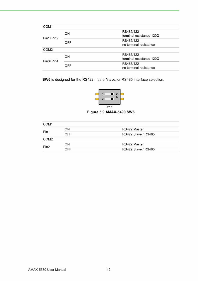
SW6 is designed for the RS422 master/slave, or RS485 interface selection.
Figure 5.9 AMAX-5490 SW6
COM1
Pin1+Pin2ON RS485/422
terminal resistance 120Ω
OFF RS485/422no terminal resistance
COM2
Pin3+Pin4ON RS485/422
terminal resistance 120Ω
OFF RS485/422no terminal resistance
COM1
Pin1ON RS422 MasterOFF RS422 Slave / RS485
COM2
Pin2ON RS422 MasterOFF RS422 Slave / RS485
43 AMAX-5580 User Manual
Chapter 5
PCIe Expansion M
odule
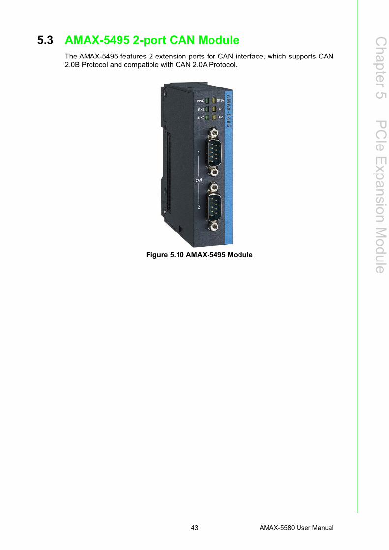
5.3 AMAX-5495 2-port CAN ModuleThe AMAX-5495 features 2 extension ports for CAN interface, which supports CAN2.0B Protocol and compatible with CAN 2.0A Protocol.
Figure 5.10 AMAX-5495 Module

AMAX-5580 User Manual 44
5.3.1 AMAX-5495 Specification
General:
Serial Communication:
Protection:
Environment:
Certification CE, FCC class A
Connector 2 x DB9
Enclosure Aluminum housing
Power Consumption 3W@24VDC
Bus Interface PCIe x1
LED Indicator PWR, Standby, TX/RX
Protocol CAN2.0 A/B
Data Transfer Rate 1Mbits/s
DB9 2 - CAN_N7 - CAN_P3 - CAN_ISO1, 4, 5, 6, 8, 9 - NC
ESD Protection 8KV (air), 4KV (contact)
EFT Protection 2,000 VDC (Power Line)
Isolation Protection 2,500 VDC (between COM port and backplane)
Operation Temperature -10~60°C (vertical mounted)
Storage Temperature -40~85°C
Relative Humidity 5~95% (non-condense)
45 AMAX-5580 User Manual
Chapter 5
PCIe Expansion M
odule
5.3.2 LED Indicator
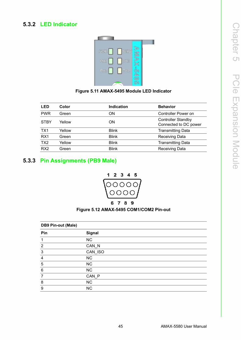
Figure 5.11 AMAX-5495 Module LED Indicator
5.3.3 Pin Assignments (PB9 Male)
Figure 5.12 AMAX-5495 COM1/COM2 Pin-out
LED Color Indication BehaviorPWR Green ON Controller Power on
STBY Yellow ON Controller StandbyConnected to DC power
TX1 Yellow Blink Transmitting DataRX1 Green Blink Receiving DataTX2 Yellow Blink Transmitting DataRX2 Green Blink Receiving Data
DB9 Pin-out (Male)
Pin Signal1 NC2 CAN_N3 CAN_ISO4 NC5 NC6 NC7 CAN_P8 NC9 NC
AMAX-5580 User Manual 46
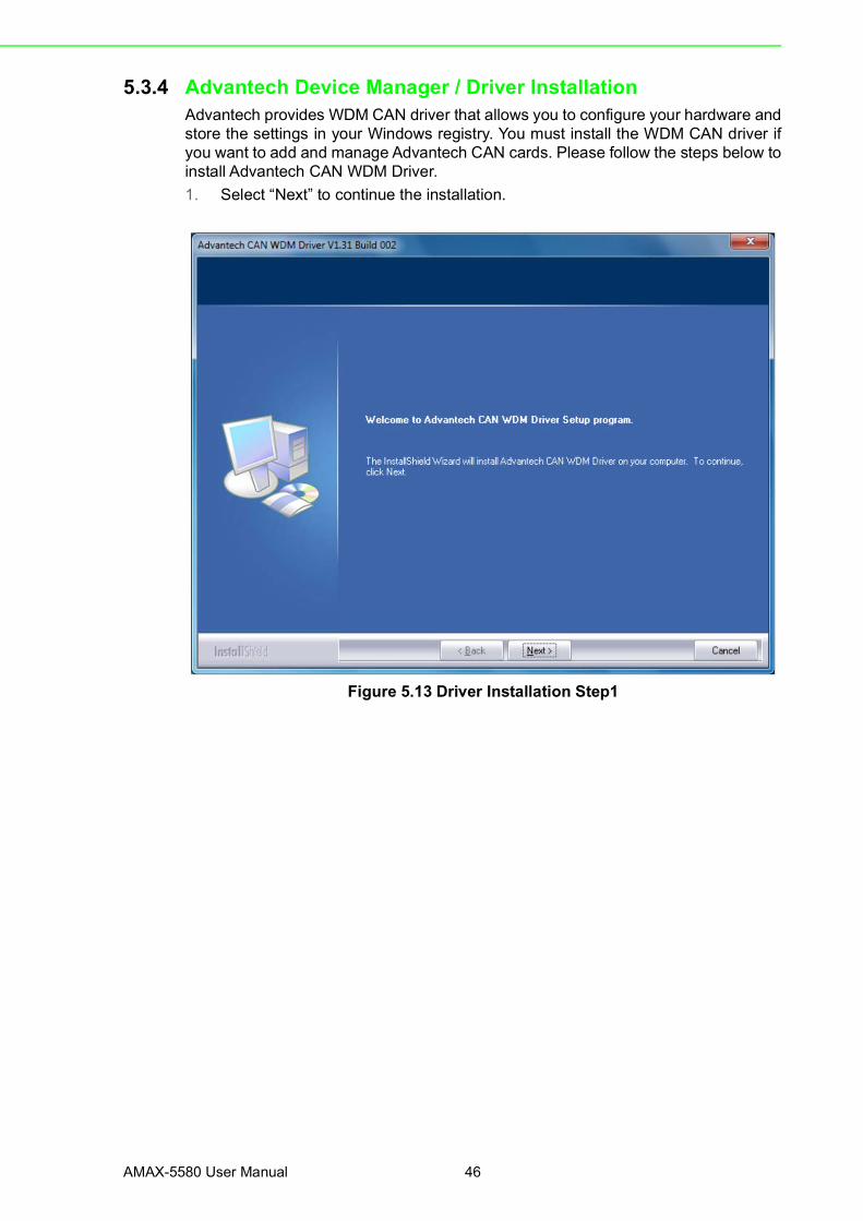
5.3.4 Advantech Device Manager / Driver InstallationAdvantech provides WDM CAN driver that allows you to configure your hardware andstore the settings in your Windows registry. You must install the WDM CAN driver ifyou want to add and manage Advantech CAN cards. Please follow the steps below toinstall Advantech CAN WDM Driver.1. Select “Next” to continue the installation.
Figure 5.13 Driver Installation Step1

47 AMAX-5580 User Manual
Chapter 5
PCIe Expansion M
odule
2. After a while, the installation will be complete.
Figure 5.14 Driver Installation Step2
3. After the physical hardware has been installed, the card will be automatically detected.
Figure 5.15 Driver Installation Step3
AMAX-5580 User Manual 48
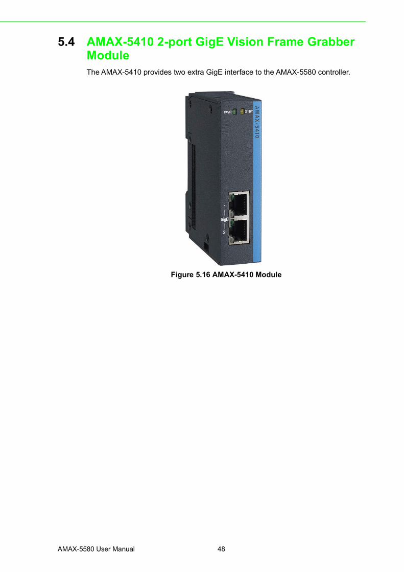
5.4 AMAX-5410 2-port GigE Vision Frame Grabber ModuleThe AMAX-5410 provides two extra GigE interface to the AMAX-5580 controller.
Figure 5.16 AMAX-5410 Module
49 AMAX-5580 User Manual
Chapter 5
PCIe Expansion M
odule
5.4.1 AMAX-5410 Specification
General:
Ethernet:
Protection:
Environment:
5.4.2 LED Indicator
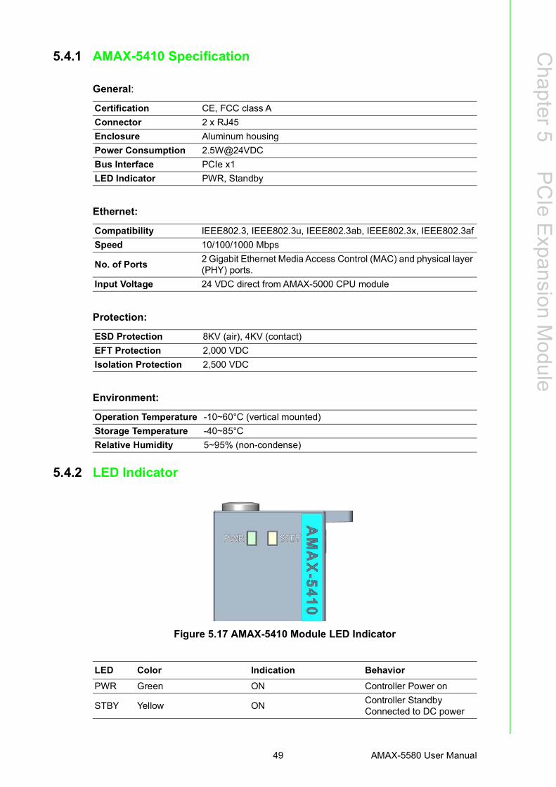
Figure 5.17 AMAX-5410 Module LED Indicator
Certification CE, FCC class AConnector 2 x RJ45Enclosure Aluminum housingPower Consumption 2.5W@24VDCBus Interface PCIe x1LED Indicator PWR, Standby
Compatibility IEEE802.3, IEEE802.3u, IEEE802.3ab, IEEE802.3x, IEEE802.3afSpeed 10/100/1000 Mbps
No. of Ports 2 Gigabit Ethernet Media Access Control (MAC) and physical layer (PHY) ports.
Input Voltage 24 VDC direct from AMAX-5000 CPU module
ESD Protection 8KV (air), 4KV (contact)EFT Protection 2,000 VDCIsolation Protection 2,500 VDC
Operation Temperature -10~60°C (vertical mounted)Storage Temperature -40~85°CRelative Humidity 5~95% (non-condense)
LED Color Indication BehaviorPWR Green ON Controller Power on
STBY Yellow ON Controller StandbyConnected to DC power

AMAX-5580 User Manual 50
5.5 AMAX-5410P 2-port PoE Vision Frame Grabber ModuleThe AMAX-5410P provides two extra ports of GigE interface with PoE interface tothe AMAX-5580 controller. The maximum power is 15W per port; and maximum 20Wfor entire module DC output to the external PoE devices. The power comes from theinternal PCIe bus, so no external power is needed.
Figure 5.18 AMAX-5410P Module

51 AMAX-5580 User Manual
Chapter 5
PCIe Expansion M
odule
5.5.1 AMAX-5410P Specification
General:
Ethernet:
Protection:
Environment:
Certification CE, FCC class AConnector 2 x RJ45Enclosure Aluminum housingPower Consumption 2.5W@24VDCBus Interface PCIe x1LED Indicator PWR, Standby
Compatibility IEEE802.3, IEEE802.3u, IEEE802.3ab, IEEE802.3x, IEEE802.3afSpeed 10/100/1000 Mbps
No. of Ports 2 Gigabit Ethernet Media Access Control (MAC) and physical layer (PHY) ports.
Input Voltage 24 VDC direct from AMAX-5000 CPU module
Output PoE Power 48 VDC PoE Power output, 15W per port, total Max.20W (AMAX-5410P only)
ESD Protection 8KV (air), 4KV (contact)EFT Protection 2,000 VDCIsolation Protection 2,500 VDC
Operation Temperature -10~60°C (vertical mounted)Storage Temperature -40~85°CRelative Humidity 5~95% (non-condense)

AMAX-5580 User Manual 52
5.5.2 LED Indicator
Figure 5.19 AMAX-5410P Module LED Indicator
LED Color Indication BehaviorPWR Green ON Controller Power on
STBY Yellow ON Controller Standby Connected to DC power
1 Green ON Port1 is connected2 Green ON Port2 is connected

53 AMAX-5580 User Manual
Chapter 5
PCIe Expansion M
odule
5.6 AMAX-5400E PCIe mini card expansion moduleThe AMAX-5400E module provides additional PCIe mini card and SIM card slot tothe AMAX-5580 controller. It can be also installed an antenna on the top of the mod-ule to enhance the wireless signal.
Figure 5.20 AMAX-5400E Module
5.6.1 AMAX-5400E Specification
General:
Expansion Function:
Environment:
Certification CE, FCC class AEnclosure Aluminum housingPower Consumption 0.5W@24VDCBus Interface PCIe x1LED Indicator PWR, Standby
Interface Full size mini PCI express 2.0SIM card slot Mini SIM cardAntenna 1x SMA hole on the top
Operation Temperature -10~60°C (vertical mounted)Storage Temperature -40~85°CRelative Humidity 5~95% (non-condense)

AMAX-5580 User Manual 54
5.6.2 LED Indicator
Figure 5.21 AMAX-5400E Module LED Indicator
5.6.3 PCIe Mini Card Installation GuideIn order to install PCIe mini card and Antenna (if needed), please remove side cover,the PCIe mini card slot and mounting hole's position is shown as below figure.
Figure 5.22 AMAX-5400E PCIe mini card installation guide
LED Color Indication BehaviorPWR Green ON Controller Power on
STBY Yellow ON Controller StandbyConnected to DC power

Appendix AA Pin Assignments
AMAX-5580 User Manual 56
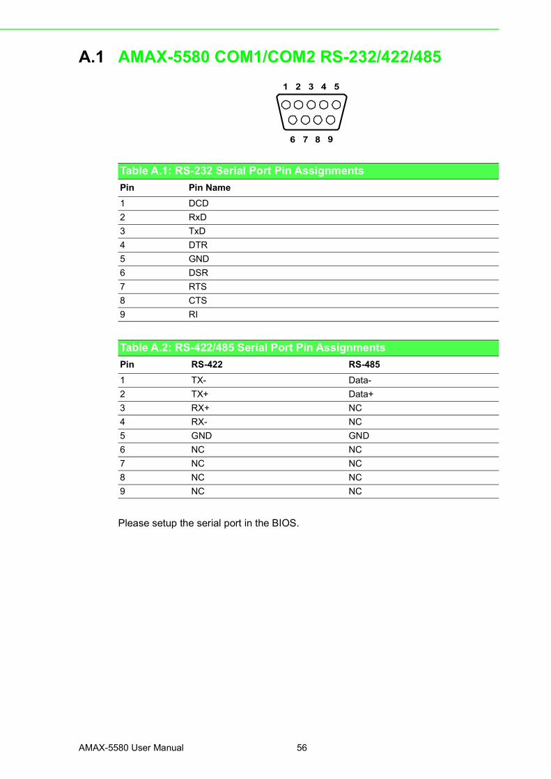
A.1 AMAX-5580 COM1/COM2 RS-232/422/485
Please setup the serial port in the BIOS.
Table A.1: RS-232 Serial Port Pin AssignmentsPin Pin Name1 DCD2 RxD3 TxD4 DTR5 GND6 DSR7 RTS8 CTS9 RI
Table A.2: RS-422/485 Serial Port Pin AssignmentsPin RS-422 RS-4851 TX- Data-2 TX+ Data+3 RX+ NC4 RX- NC5 GND GND6 NC NC7 NC NC8 NC NC9 NC NC
1 5
96
32 4
7 8

57 AMAX-5580 User Manual
Appendix APin Assignm
ents
A.2 AMAX-5580 USB Connector
A.3 AMAX-5580 HDMI Display Connector
Table A.3: USB 3.0 Connector Pin AssignmentsPin Signal Name Description1 VBUS Power2 D-
USB2.0 differential pair3 D+4 GND Ground for power return5 StdA_SSRX-
SuperSpeed receiver differential pair6 StdA_SSRX+7 GND_DRIAN Ground for signal return8 StdA_SSTX-
SuperSpeed transmitter differential pair9 StdA_SSTX+
Table A.4: HDMI Display ConnectorPin Signal Pin Signal1 TMDS Data2+ 2 TMDS Data2 Shield3 TMDS Data2- 4 TMDS Data1+5 TMDS Data1 Shield 6 TMDS Data1-7 TMDS Data0+ 8 TMDS Data0 Shield9 TMDS Data0- 10 TMDS Clock+11 TMDS Clock Shield 12 TMDS Clock-13 CEC 14 Reserved15 SCL 16 SDA17 DDC/CEC/HEC Ground 18 +5 V Power (max 50 mA)19 Hot Plug Detect
AMAX-5580 User Manual 58
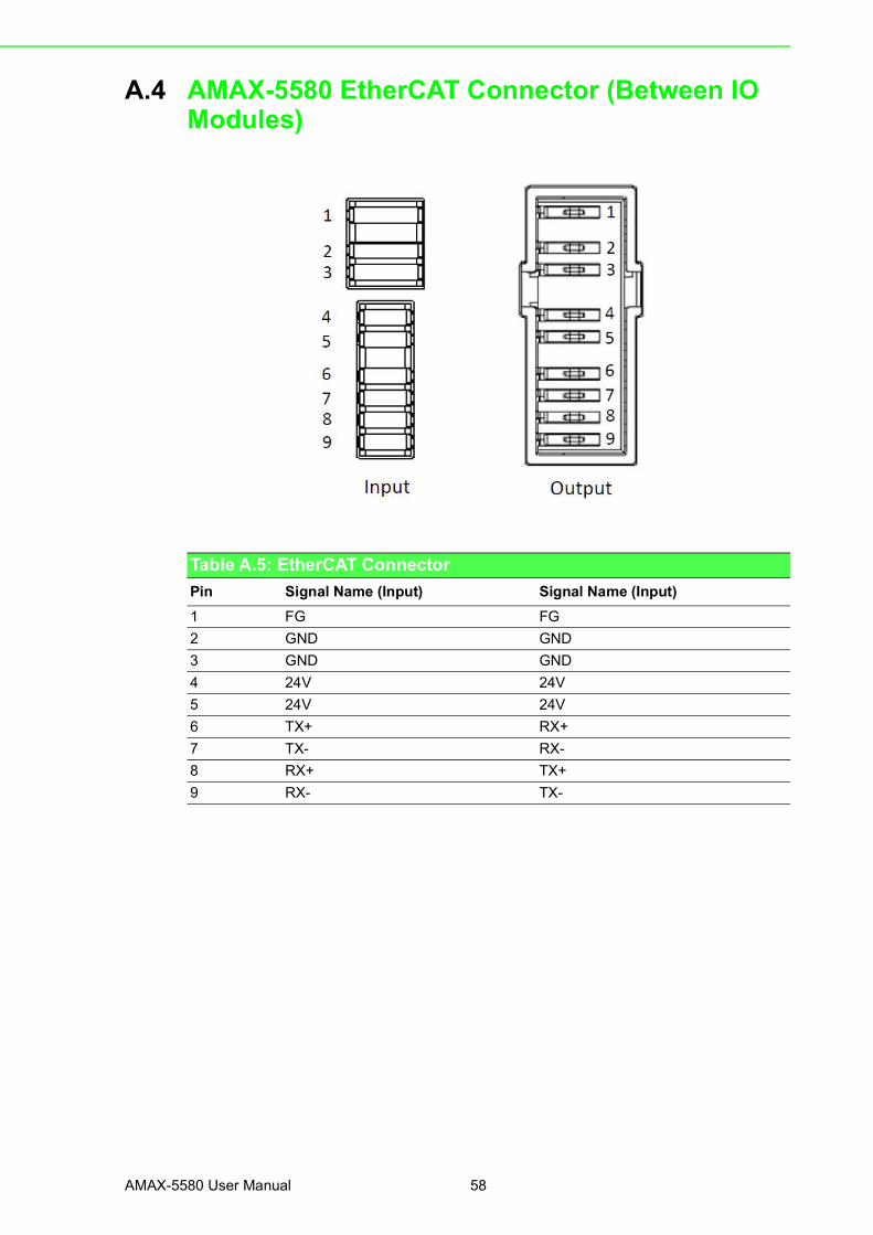
A.4 AMAX-5580 EtherCAT Connector (Between IO Modules)
Table A.5: EtherCAT ConnectorPin Signal Name (Input) Signal Name (Input)1 FG FG2 GND GND3 GND GND4 24V 24V5 24V 24V6 TX+ RX+7 TX- RX-8 RX+ TX+9 RX- TX-
59 AMAX-5580 User Manual
Appendix APin Assignm
ents
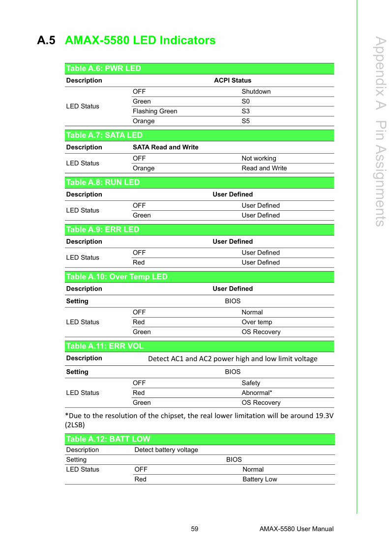
A.5 AMAX-5580 LED Indicators
*Due to the resolution of the chipset, the real lower limitation will be around 19.3V(2LSB)
Table A.6: PWR LEDDescription ACPI Status
LED Status
OFF ShutdownGreen S0Flashing Green S3Orange S5
Table A.7: SATA LEDDescription SATA Read and Write
LED StatusOFF Not workingOrange Read and Write
Table A.8: RUN LEDDescription User Defined
LED StatusOFF User DefinedGreen User Defined
Table A.9: ERR LEDDescription User Defined
LED StatusOFF User DefinedRed User Defined
Table A.10: Over Temp LEDDescription User Defined
Setting BIOS
LED StatusOFF NormalRed Over tempGreen OS Recovery
Table A.11: ERR VOLDescription Detect AC1 and AC2 power high and low limit voltage
Setting BIOS
LED StatusOFF SafetyRed Abnormal*Green OS Recovery
Table A.12: BATT LOWDescription Detect battery voltageSetting BIOSLED Status
OFF NormalRed Battery Low

www.advantech.comPlease verify specifications before quoting. This guide is intended for referencepurposes only.All product specifications are subject to change without notice.No part of this publication may be reproduced in any form or by any means,electronic, photocopying, recording or otherwise, without prior written permis-sion of the publisher.All brand and product names are trademarks or registered trademarks of theirrespective companies.© Advantech Co., Ltd. 2020


