39
Ambler Mining District Access September 2011 Design Criteria Memorandum

Ambler Mining District Access
September 2011
Design CriteriaMemorandum

AMBLER MINING DISTRICT ACCESS
DESIGN CRITERIA MEMORANDUM
AKSAS 63812
Prepared for:
State of Alaska Department of Transportation and Public Facilities
2301 Peger Road Fairbanks, Alaska 99709
Prepared by:
DOWL HKM 4041 B Street
Anchorage, Alaska 99503 (907) 562-2000
September 2011
Ambler Mining District Access Design Criteria Memorandum AKSAS 63812
TABLE OF CONTENTS Page
Page i
1.0 INTRODUCTION ...............................................................................................................11.1 Project Overview and Purpose ..........................................................................................11.2 Project Study Area ............................................................................................................11.3 Objectives .........................................................................................................................11.4 General Corridor Description ...........................................................................................2
2.0 ROADWAY DESIGN CRITERIA......................................................................................62.1 General Criteria .................................................................................................................6
2.1.1 Functional Classification ............................................................................................62.1.2 Design Vehicle ............................................................................................................82.1.3 Design Speed and Grade Limitations .........................................................................92.1.4 Clear Zone .................................................................................................................102.1.5 Projected Average Annual Daily Traffic (AADT) ...................................................102.1.6 Typical Section .........................................................................................................102.1.7 Turnouts ....................................................................................................................112.1.8 Structural Section ......................................................................................................12
2.1.8.1 Thermal Modeling - Transient Analysis ..........................................................132.1.8.2 Thermal Modeling - Corridor Soil Profile .......................................................132.1.8.3 Thermal Modeling - Air Temperature .............................................................132.1.8.4 Thermal Modeling - Thermal Properties of Soils ............................................142.1.8.5 Thermal Modeling - Boundary Conditions ......................................................142.1.8.6 Thermal Modeling - Analysis ..........................................................................14
2.2 Roadway Bridge and Culvert Criteria .............................................................................152.2.1 Design Flood .............................................................................................................152.2.2 Culvert Sizing ...........................................................................................................152.2.3 Design Live Load ......................................................................................................15
3.0 RAILWAY DESIGN CRITERIA......................................................................................163.1 General Criteria ...............................................................................................................16
3.1.1 Classification and Estimated Traffic .........................................................................183.1.2 Design Speed ............................................................................................................193.1.3 Grade Limitations .....................................................................................................193.1.4 Typical Section .........................................................................................................193.1.5 Geometric Criteria ....................................................................................................22
3.2 Railway Bridge Criteria ..................................................................................................233.2.1 Design Flood .............................................................................................................233.2.2 Design Live Load ......................................................................................................233.2.3 Culvert Sizing and Cover Heights ............................................................................23
4.0 FISH PASSAGE CRITERIA .............................................................................................23
5.0 REFERENCES ..................................................................................................................25

Ambler Mining District Access Design Criteria Memorandum AKSAS 63812
TABLE OF CONTENTS (cont) Page
Page ii
TABLES Table 1: Initial Roadway Design Criteria Comparison ...................................................................7Table 2: Structural Section Summary ...........................................................................................12Table 3: Assumed Thermal Properties of Materials .....................................................................14Table 4: Structural Section Summary ...........................................................................................15Table 5: Initial Railway Design Criteria .......................................................................................17Table 6: FRA Classes of Railroad Track ......................................................................................18
FIGURES Figure 1: Mining Claims and Mineral Resources ...........................................................................3Figure 2: Location and Vicinity Map ..............................................................................................4Figure 3: Preliminary Corridors ......................................................................................................5Figure 4: Multi Axle Module Trailers ............................................................................................9Figure 5: Ambler Mining District Access Typical Section ..........................................................11Figure 6: Ambler Mining District Typical Section .......................................................................12Figure 7: 141-lb RE Rail Section ..................................................................................................20Figure 8: Railway Mainline Typical Section ................................................................................21Figure 9: Railroad Typical Section with Siding Track .................................................................22
APPENDIX
Appendix A ....................................................................... Thermal Modeling-Thaw Depth Figures

Ambler Mining District Access Design Criteria Memorandum AKSAS 63812
Page 1
1.0 INTRODUCTION
1.1 Project Overview and Purpose
The Ambler Mining District Access project proposes to identify, design, and construct a
transportation corridor from the Ambler mineral belt to either a port location on the west coast of
Alaska or the surface transportation system in the Alaska Interior. The corridor is intended to
provide surface transportation access to state lands and facilitate exploration and development of
mineral resources along the Ambler mineral belt.
The South Flank of the Brooks Range contains extensive mineral resources. Limited exploration
efforts since the 1950s have identified significant resources of copper and other base metals
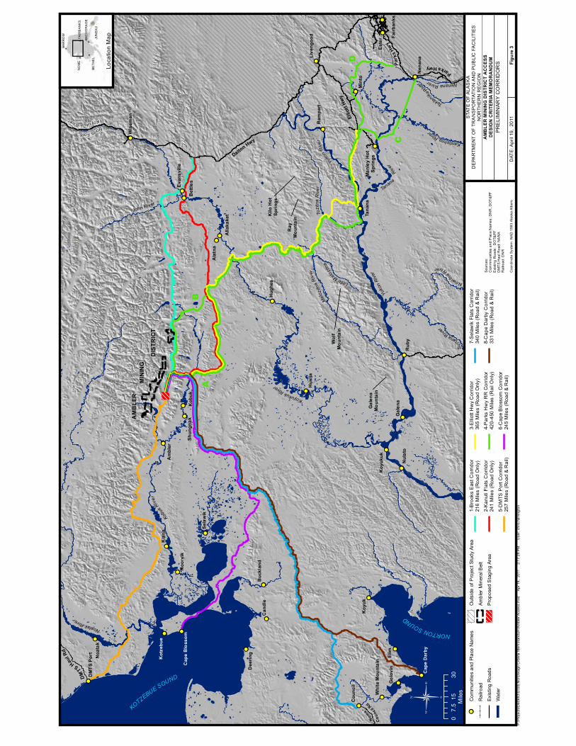
(Hawley and Vant, 2009) (Figure 3). Exploration and development of these deposits has been
economically and logistically curtailed by the lack of transportation infrastructure.
1.2 Project Study Area
The project study area extends from Ambler mineral belt south to Nenana and from the Dalton
Highway to the west coast (Figure 1). Four potential corridors have been identified from the
Ambler mineral belt to the west coast of Alaska, and four potential corridors head east from the
Ambler mineral belt to the Dalton Highway or the Alaska Railroad (Figure 2).
1.3 Objectives
This Design Criteria Memorandum documents the initial review of road and rail corridors that
could potentially access the Ambler mineral belt. The objectives for documenting the
development of the corridors for this project are:
Protect transportation corridor infrastructure and reduce the risks of failure;
Establish consistency within the corridor;
Minimize impacts to environmental resources; and
Minimize long-term maintenance costs.
The design criteria set forth in this memorandum targets these objectives by:

Ambler Mining District Access Design Criteria Memorandum AKSAS 63812
Page 2
Documenting roadway and railway criteria that will guide design decisions for the entire
the corridor;
Identifying criteria that provide designers with geometric flexibility to minimize
environmental impacts; and
Developing predominantly fill cross-sections with depth that addresses thermal modeling,
snow drifting, and settlement issues.
1.4 General Corridor Description
A Corridor Development Memorandum (DOWL HKM, 2011) was prepared to document the
selection of eight potential road and rail transportation access corridors. These eight potential
corridors were developed based on historic transportation corridors (e.g., winter trails, tractor
trails, etc.) previous, access studies, topographic information, slope analysis, and aerial imagery.
Four corridors start in the Ambler mineral belt and head west or southwest to existing or
potential port sites on the Alaskan coast. Four corridors head east or southeast to the Dalton
Highway or to the existing Alaska Railroad facilities near Nenana (See Figure 2).

!(!(
!(
!(
!(
!(
!( !(
!(
!(!( !(
!(!( !(!(
!(!(!(!(
!(!(!(
!(
!(!( !( !(!(
!(
!(!(
!(
!( !( !(!( !(!(!(
!(!( !(
!( !( !(!(
!(!( !( !(!(!( !(!(!(!( !(
!(
!(
!( !(!( !( !(!(
!(!(
!(!(!(!(
!(!(!( !(!(!( !(!(!(!(!(!(
!(!(
!(!(!( !( !( !(!(!(
!(!(
!(!(!(
!(
!(
!(!(
!(
! (!(
!( !(!(!(
!(!(
!(!(
!(
!(
!(!(
!(
!(!(
!(!( !( !(
!( !(!( !(!(!(!(
!(
!(!(!(!(
!(!( !(
!(
!(!(
!(!(!(
!(
!(
!(!(!(
!(!(!(
!(!(!(!(
!( !(
!(
!(!(!(!(!(
!(
!(!(!(
!(!(!(
!(!(
!(
!(
!(!(!(
!(!(!(
!(!(!(
!(!(!(
!(
!(
!(!(
!(!(!(
!(!(
!(
!(
!(
!(
!(
!(
!(!( !( !(
!(!( !(
!(!(!(
!(
!(
!( !(
!(
!(
!(
!(
!(
!(!(
!(!(!(!(
!(
!(
!(
!(!(
!(
!(!( !(
!( !(!(!(
!(!(
!(
!(
!(
!(
!(!( !(
!(!(!(
!(!(
!(
!(!(!(!(!(
!(
!(
!(!(
!(
!(
!(!(
!(
!!
!!
!!!!
!!!!
!!!!
!!
!!!!
!!!!
!!!!
!!!!
!!
!!!!
!!
!!!!
!!
!!
!!!!
!!
!!!!
!!!!
!!
!!!!
!!
!!
!!
%,%,
%,%,
%,
%,
Elim
Rub
y
Kia
na
Kob
uk
Min
toK
oyuk
Este
r
Noa
tak
Am
bler
Ala
tna
Can
dle
Hug
hes
Hus
lia
Tana
na
Nul
ato
Gal
ena
Nen
ana
Wis
eman
Noo
rvik
Bet
tles
Sela
wik
Dee
ring
Ram
part
Cou
ncil
Koy
ukuk
Gol
ovin
Kot
zebu
e
Shun
gnak
Buc
klan
d
Alla
kake
t
Live
ngoo
d Fairb
anks
Evan
svill
e
Whi
te M
ount
ain
Man
ley
Hot
Sprin
gs
DM
TS P
ort
Cap
e B
loss
om
Cap
e D
arby
KOTZEBUESOUND
NORTONSOUND
YukonRiver
MelozitnaRiver
Koyukuk
River
TozitnaRi ver
John River
NorthFork
KoyukukRiver
NoatakR
iver
NenanaRiver
Teklan
ika
River
KantishnaRi
ver
Nowitn
aRiver
Sul
tanaRiver
Tanana
River
Yu
konRiver
KobukRiver
LittleMe
lozitna
Dalton Hwy
ParksHwy
Nom
e-
Cou
ncilRd
Ellio
ttHw
y
DM
TSHaulR
d
Par
ksHw
y
AM
BLE
RM
INER
AL
BEL
T
P:\P
roje
cts\
D60
693\
GIS
\EN
G\D
esig
n C
riter
ia M
emor
andu
m\M
inin
g C
laim
s an
d M
iner
al O
ccur
renc
es.m
xd
Apr
19,
201
1
2:1
8:27
PM
Use
r: c
hris
.har
ringt
on
STA
TE
OF
ALA
SK
AD
EPA
RTM
EN
T O
F TR
AN
SP
OR
TATI
ON
AN
D P
UB
LIC
FA
CIL
ITIE
SN
OR
THE
RN
RE
GIO
NA
MB
LER
MIN
ING
DIS
TRIC
T A
CC
ESS
DES
IGN
CR
ITER
IA M
EMO
RA
ND
UM
MIN
ING
CLA
IMS
AN
DM
INE
RA
L O
CC
UR
RE
NC
ES
DAT
E: A
pril
19,
2011
Figu
re 1
!!C
omm
uniti
es a
nd P
lace
Nam
es
Rai
lroad
Exis
ting
Roa
ds
Wat
er
Out
side
of P
roje
ct S
tudy
Are
a
Ambl
er M
iner
al B
elt
Prel
imin
ary
Cor
ridor
s
Prop
osed
Sta
ging
Are
a
!(M
iner
al O
ccur
renc
es
%,N
atur
ally
Occ
urin
g A
sbes
tos
Fede
ral M
inin
g C
laim
s
Stat
e M
inin
g C
laim
s
015
307.
5 Mile
s
NO
ME
BAR
RO
W
BETH
EL
FAIR
BAN
KS
ANC
HO
RA
GE
JUN
EAU
Loca
tion
Map
Sou
rces
:Fe
dera
l Min
ing
Cla
ims:
BLM
Sta
te M
inin
g C
laim
s:D
NR
Min
eral
Occ
urre
nce:
Rep
ort o
n M
iner
als
- C
.C. H
awle
y &
M.K
. Van
t, Fe
brua
ry 2
009
Coo
rdin
ate
Sys
tem
: NA
D 1
983
Ala
ska
Alb
ers

BEAUFORT SEA
ARCTIC OCEAN
KOTZEBUE
SOUND
NORTON SOUND
BRISTOL BAY
GULF OF ALASKA
Brooks Range
Dalton Hwy
AmblerMineralBelt
ANAKTUVUK PASS
TeshekpukLake
TOK
NOME
HOMER
BARROW
TANANA
KODIAK
BETHEL
BETTLES
McGRATH
KOTZEBUE
FAIRBANKS
ANCHORAGE
GLENNALLEN
DILLINGHAM
PRUDHOE BAY
P:\Projects\D60693\GIS\ENG\Design Criteria Memorandum\Location Vicinity Map.mxd Apr 19, 2011 2:17:57 PM User: chris.harrington
STATE OF ALASKADEPARTMENT OF TRANSPORTATION AND PUBLIC FACILITIES
NORTHERN REGION
LOCATION & VICINITY MAP
DATE: April 19, 2011 Figure 2
0 100 20050Miles
NOME
BARROW
BETHEL
FAIRBANKS
ANCHORAGE
JUNEAU
Location Map
STUDY AREA
CANADA
UNITE
DSTATES
AMBLER MINING DISTRICT ACCESSDESIGN CRITERIA MEMORANDUM
Sources:Cities: Alaska Department of Natural Resources (DNR)Alaska Hillshade: DNR
Coordinate System: NAD 1983 Alaska Albers
!!
!!
!!!!
!!!!
!!!!
!!
!!!!
!!!!
!!!!
!!!!
!!
!!!!
!!
!!!!
!!
!!
!!!!
!!
!!!!
!!!!
!!
!!!!
!!
!!
!!
Elim
Rub
y
Kia
na
Kob
uk
Min
toK
oyuk
Este
r
Noa
tak
Am
bler
Ala
tna
Can
dle
Hug
hes
Hus
lia
Tana
na
Nul
ato
Gal
ena
Nen
ana
Wis
eman
Noo
rvik
Bet
tles
Sela
wik
Dee
ring
Ram
part
Cou
ncil
Koy
ukuk
n
Gol
ovin
Kot
zebu
e
Shun
gnak
Buc
klan
d
Alla
kake
t
Live
ngoo
d Fairb
anks
Evan
svill
e
Whi
te M
ount
ain
Man
ley
Hot
Sprin
gs
DM
TS P
ort
Cap
e B
loss
om
Cap
e D
arby
KOTZEBUESOUND
NORTONSOUND
YukonRiver
MelozitnaRiver
Koyukuk
River
TozitnaRi ver
John River
NorthFork
KoyukukRiver
NoatakR
iver
NenanaRiver
Teklan
ika
River
KantishnaR
iver
Nowitn
aRiver
Su
ltanaRive
r
Tanana
River
Yu
konRiver
KobukRiver
LittleMe
lozitna
Dalton Hwy
ParksHwy
Nom
e-
Cou
ncilRd
Ellio
ttHw
y
DM
TSHaulR
d
Park
sHw
y
AM
BLE
RM
ININ
G
DIS
TRIC
T
AB
C
D
Wol
fM
ount
ain
Ray
Mou
ntai
nKilo
Hot
Sprin
gs
Gal
ena
Mou
ntai
n
P:\P
roje
cts\
D60
693\
GIS
\EN
G\D
esig
n C
riter
ia M
emor
andu
m\A
mbl
er A
cces
s.m
xd
Apr
19,
201
1
2:1
7:29
PM
Use
r: ch
ris.h
arrin
gton
STA
TE
OF
ALA
SK
AD
EPA
RTM
EN
T O
F TR
AN
SP
OR
TATI
ON
AN
D P
UB
LIC
FA
CIL
ITIE
SN
OR
THE
RN
RE
GIO
NA
MB
LER
MIN
ING
DIS
TRIC
T A
CC
ESS
DES
IGN
CR
ITER
IA M
EMO
RA
ND
UM
PR
ELI
MIN
AR
Y C
OR
RID
OR
S
DAT
E: A
pril
19,
2011
Figu
re 3
!!C
omm
uniti
es a
nd P
lace
Nam
es
Rai
lroad
Exis
ting
Roa
ds
Wat
er
Out
side
of P
roje
ct S
tudy
Are
a
Ambl
er M
iner
al B
elt
Prop
osed
Sta
ging
Are
a
1-B
rook
s E
ast C
orrid
or21
6 M
iles
(Roa
d O
nly)
2-K
anut
i Fla
ts C
orrid
or24
1 M
iles
(Roa
d O
nly)
5-D
MTS
Por
t Cor
ridor
257
Mile
s (R
oad
& R
ail)
3-E
lliot
t Hw
y C
orrid
or36
5 M
iles
(Roa
d O
nly)
4-P
arks
Hw
y R
R C
orrid
or42
0-45
0 M
iles
(Rai
l Onl
y)
6-C
ape
Blo
ssom
Cor
ridor
245
Mile
s (R
oad
& R
ail)
7-S
elaw
ik F
lats
Cor
ridor
340
Mile
s (R
oad
& R
ail)
8-C
ape
Dar
by C
orrid
or33
1 M
iles
(Roa
d &
Rai
l)
015
307.
5 Mile
s
NO
ME
BAR
RO
W
BETH
EL
FAIR
BAN
KS
ANC
HO
RA
GE
JUN
EAU
Loca
tion
Map
Sou
rces
:C
omm
mun
ities
and
Pla
ce N
ames
: DN
R, D
OT
&P
FE
xist
ing
Roa
ds:
DO
T&P
FD
MT
S H
aul R
oad:
NA
NA
Rai
lroad
: DN
R
Coo
rdin
ate
Sys
tem
: NA
D 1
983
Ala
ska
Alb
ers
Ambler Mining District Access Design Criteria Memorandum AKSAS 63812
Page 6
2.0 ROADWAY DESIGN CRITERIA
2.1 General Criteria
Design criteria for the Ambler mineral belt were generated from published guidelines from the
American Association of State Highway and Transportation Officials (AASHTO). Additional
design criteria were developed from State of Alaska Department of Transportation and Public
Facilities (DOT&PF) bridge designers, private bridge fabricators, professionals with heavy-haul
design experience, and past planning reports on similar DOT&PF Northern Region road and
bridge projects.
The design criteria, comparison data, and criteria source or rationale are presented in Table 1. A
detailed explanation of the criteria follows.
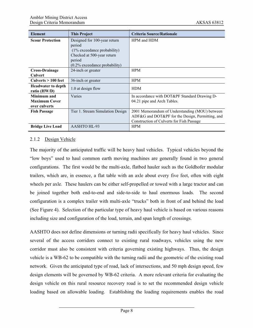
2.1.1 Functional Classification
Ambler mineral belt corridors are classified as Very Low-Volume Local Roads with the sub-
classification of Rural Resource Recovery Roads. The Guidelines for Geometric Design of Very
Low-Volume Local Roads (GDVLVLR) states that this type of road is “functionally classified as
a local road and has a design average daily traffic volume of 400 vehicles per day or less.” Rural
Resource Recovery Roads are defined as “local roads serving logging or mining operations.”
Their intended use is “primarily or exclusively by professional drivers with large vehicles.”

Ambler Mining District Access Design Criteria Memorandum AKSAS 63812
Page 7
Table 1: Initial Roadway Design Criteria Comparison
Element This Project Criteria Source/Rationale
Project Type New Construction Scope of Services Functional Classification
Very Low-Volume Local Road (Special Purpose)
GDVLVLR, page 7
Functional Sub classification
Rural Resource Recovery Road GDVLVLR, page 7
Functional Classification As defined by AASHTO
Local roads serving logging or mining operations. They are primarily used by vehicles involved with resource recovery and the driving population primarily consists of professional drivers with large vehicles.
GDVLVLR, page 7-8
Design Vehicle
Maximum Axle Loadings
22,000 lbs/standard axle
22,000 lbs/trunnion axle (winter only)
A 22,000 lb axle loading should cover a wide range of transportation needs including moving heavy mining equipment to the site on multi-axle heavy haul trailers. The basic truck/trailer would be the standard 8’6” wide, but loads considerably wider (such as modularized equipment) could be carried on the proposed 32-foot typical section.
Number of Lanes 2 Scope of Services Grade Limitations 50 mph - Level, 0-4%
40 mph - Level, 4-7% 40 mph - Rolling, 7-9% 40 mph -Mountainous, 9-12%
American Association of State Highway and Transportation Officials, A Policy on Geometric Design of Highways and Streets, 5th Edition, 2004, (AASHTO) page 235& 409, 414. AASHTO, page 446 (Steeper grades may necessitate lower design speeds)
Clear Zone 6 ft Recommended (4H:1V sides slopes) 0 ft Allowed (Can be 3:1 or steeper, slope stability dependent)
GDVLVLR, page 48 and 50.
Projected AADT % Truck
400 80%
2007-2009 Annual Daily Traffic Report, Northern Region for Dalton Highway (2009 AADT=300) Truck traffic: 2007-2009 Annual Daily Traffic Report, Northern Region for Dalton Highway.
Maximum Design Speed
50 mph AASHTO, page 415 The design speed will be dependent on the terrain.
Surfacing, Lanes Unpaved GDVLVLR, page 6 Minimum Traveled Way Width Lane Shoulder
32 feet 12 feet 4 feet
GDVLVLR, page 18 Exhibit 1 Page 19 discretion A wider typical section was chosen due to the anticipated high amount of heavy haul truck traffic within the Ambler mineral belt corridor.
Design Flood 50-year return period (2% exceedance probability)
Alaska Highway Preconstruction Manual (HPM) and Alaska Highway Drainage Manual (HDM).
Ambler Mining District Access Design Criteria Memorandum AKSAS 63812
Page 8
Element This Project Criteria Source/Rationale Scour Protection Designed for 100-year return
period (1% exceedance probability) Checked at 500-year return period (0.2% exceedance probability)
HPM and HDM
Cross-Drainage Culvert
24-inch or greater HPM
Culverts > 100 feet 36-inch or greater HPM Headwater to depth ratio (HW/D) 1.0 at design flow HDM
Minimum and Maximum Cover over culverts
Varies In accordance with DOT&PF Standard Drawing D-04.21 pipe and Arch Tables.
Fish Passage Tier 1. Stream Simulation Design 2001 Memorandum of Understanding (MOU) between ADF&G and DOT&PF for the Design, Permitting, and Construction of Culverts for Fish Passage
Bridge Live Load AASHTO HL-93 HPM
2.1.2 Design Vehicle
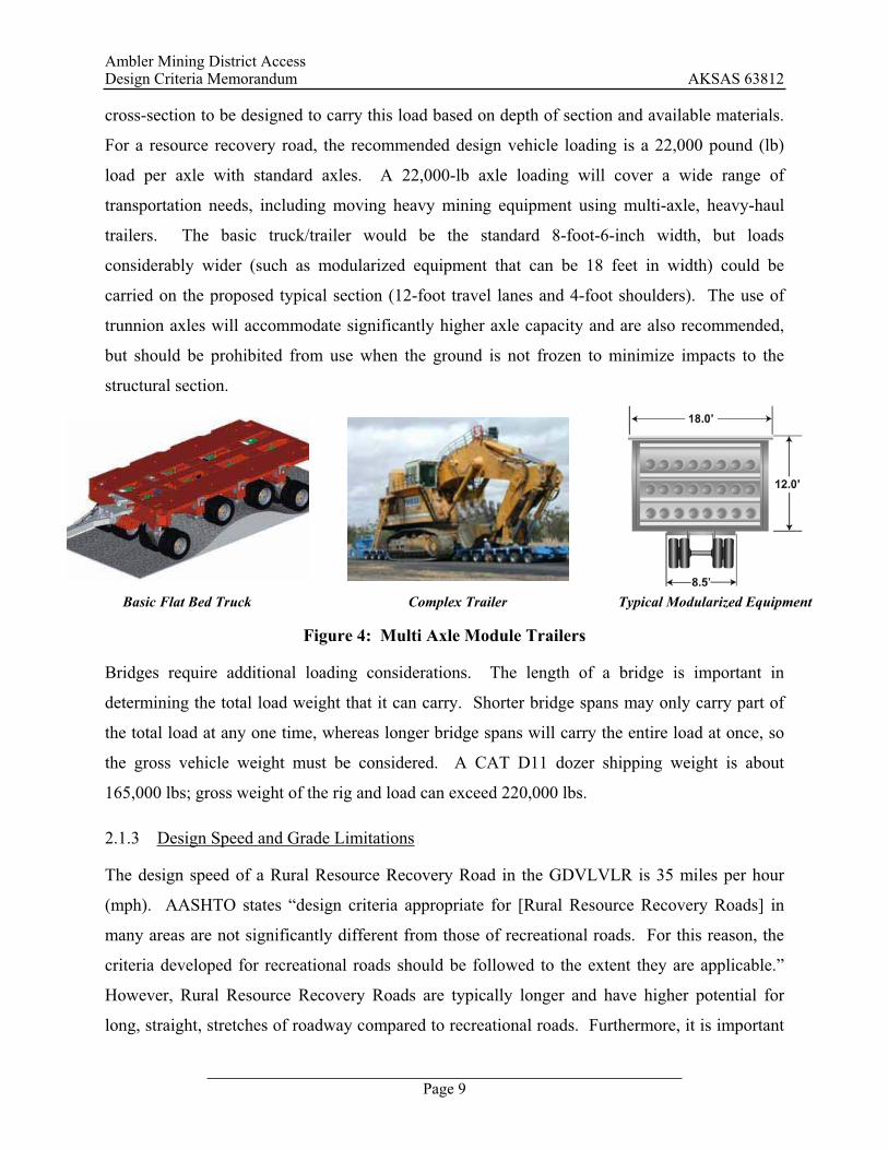
The majority of the anticipated traffic will be heavy haul vehicles. Typical vehicles beyond the
“low boys” used to haul common earth moving machines are generally found in two general
configurations. The first would be the multi-axle, flatbed hauler such as the Goldhofer modular
trailers, which are, in essence, a flat table with an axle about every five feet, often with eight
wheels per axle. These haulers can be either self-propelled or towed with a large tractor and can
be joined together both end-to-end and side-to-side to haul enormous loads. The second
configuration is a complex trailer with multi-axle “trucks” both in front of and behind the load
(See Figure 4). Selection of the particular type of heavy haul vehicle is based on various reasons
including size and configuration of the load, terrain, and span length of crossings.
AASHTO does not define dimensions or turning radii specifically for heavy haul vehicles. Since
several of the access corridors connect to existing rural roadways, vehicles using the new
corridor must also be consistent with criteria governing existing highways. Thus, the design
vehicle is a WB-62 to be compatible with the turning radii and the geometric of the existing road
network. Given the anticipated type of road, lack of intersections, and 50 mph design speed, few
design elements will be governed by WB-62 criteria. A more relevant criteria for evaluating the
design vehicle on this rural resource recovery road is to set the recommended design vehicle
loading based on allowable loading. Establishing the loading requirements enables the road
Ambler Mining District Access Design Criteria Memorandum AKSAS 63812
Page 9
cross-section to be designed to carry this load based on depth of section and available materials.
For a resource recovery road, the recommended design vehicle loading is a 22,000 pound (lb)
load per axle with standard axles. A 22,000-lb axle loading will cover a wide range of
transportation needs, including moving heavy mining equipment using multi-axle, heavy-haul
trailers. The basic truck/trailer would be the standard 8-foot-6-inch width, but loads
considerably wider (such as modularized equipment that can be 18 feet in width) could be
carried on the proposed typical section (12-foot travel lanes and 4-foot shoulders). The use of
trunnion axles will accommodate significantly higher axle capacity and are also recommended,
but should be prohibited from use when the ground is not frozen to minimize impacts to the
structural section.
Basic Flat Bed Truck Complex Trailer Typical Modularized Equipment
Figure 4: Multi Axle Module Trailers
Bridges require additional loading considerations. The length of a bridge is important in
determining the total load weight that it can carry. Shorter bridge spans may only carry part of
the total load at any one time, whereas longer bridge spans will carry the entire load at once, so
the gross vehicle weight must be considered. A CAT D11 dozer shipping weight is about
165,000 lbs; gross weight of the rig and load can exceed 220,000 lbs.
2.1.3 Design Speed and Grade Limitations
The design speed of a Rural Resource Recovery Road in the GDVLVLR is 35 miles per hour
(mph). AASHTO states “design criteria appropriate for [Rural Resource Recovery Roads] in
many areas are not significantly different from those of recreational roads. For this reason, the
criteria developed for recreational roads should be followed to the extent they are applicable.”
However, Rural Resource Recovery Roads are typically longer and have higher potential for
long, straight, stretches of roadway compared to recreational roads. Furthermore, it is important
Ambler Mining District Access Design Criteria Memorandum AKSAS 63812
Page 10
for the design speed to closely match the speed at which the majority of the drivers are
comfortable traveling, while adapting to visual and physical cues such as sight distance, lane
width, and road gradient. Due to the rural and predominantly flat terrain of the access corridors,
35 mph was deemed to be unrealistically slow. A design speed of 50 mph was selected for this
project. This design speed is similar to the Dalton Highway and other rural roads in Alaska.
During future design phases, this design speed may be reduced in rolling and mountainous
terrain at the discretion of DOT&PF.
2.1.4 Clear Zone
Provision for roadside clear zones, flatter slopes, or traffic barriers is generally inconsistent with
the economic decision to build and maintain an unpaved surface (GDVLVLR, 2001). The
GDVLVLR design guidelines for roadside clear zone width is a 6-foot or more clear recovery
area if the clear zone is considered low cost (right-of-way needed, terrain, etc.) and has minimum
environmental impacts. If the impacts are considered impractical, clear zones from 0 to 6 feet
may be used.
In areas where clear zone width is not deemed practical, side slopes can be reduced to 3H:1V or
steeper depending on the slope stability. Where horizontal curves are sharp or where
engineering judgment determines a clear zone is needed, the slopes will be 4H:1V or flatter.
2.1.5 Projected Average Annual Daily Traffic (AADT)
Dalton Highway AADT was considered in developing the design criteria for this project. Based
on the current DOT&PF traffic report (Northern Region, DOT&PF Annual Daily Traffic Report,
2007-2009), Dalton Highway AADT is about 300. A corridor from Ambler mineral belt east to
Dalton Highway is estimated to have a traffic volume equal to or less than the Dalton Highway.
Since the estimated AADT is less than 400, the GDVLVLR was used to establish basic design
criteria.
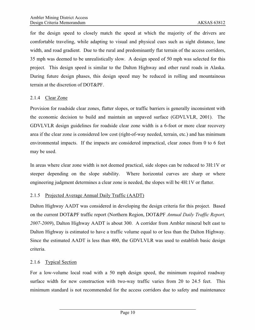
2.1.6 Typical Section
For a low-volume local road with a 50 mph design speed, the minimum required roadway
surface width for new construction with two-way traffic varies from 20 to 24.5 feet. This
minimum standard is not recommended for the access corridors due to safety and maintenance
Ambler Mining District Access Design Criteria Memorandum AKSAS 63812
Page 11
concerns for such a narrow road operating in Arctic condition with large resource recovery
vehicles. Similar Northern Region roads and the need to accommodate wide loads for
modularized equipment dictate a wider road surface. A 32-foot typical section (12-foot travel
lanes and 4-foot shoulders) which matches the Dalton Highway width is proposed. See Figure 5
for the recommended typical section. This width uses a traveled way width that matches the
minimum requirements, and adds a 4-foot shoulder to resolve the safety and maintenance
concerns.
Figure 5: Ambler Mining District Access Typical Section
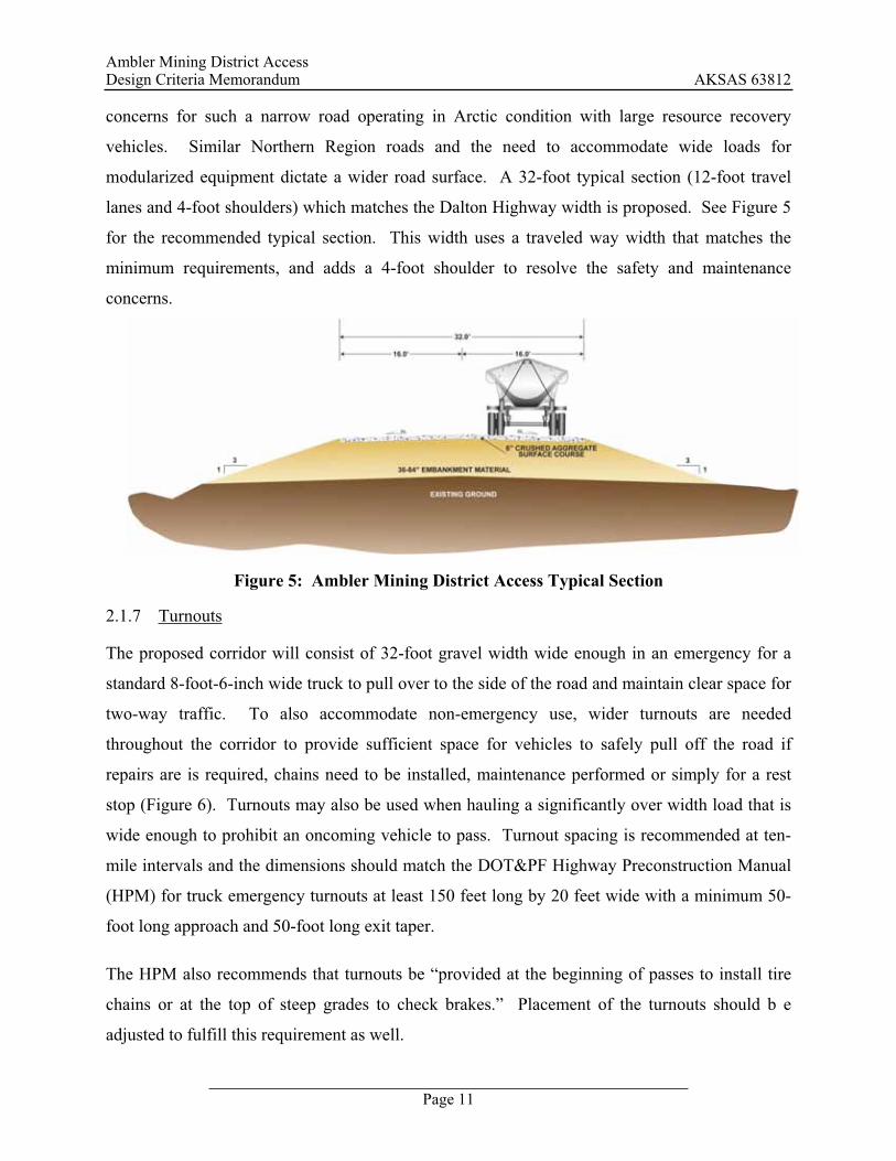
2.1.7 Turnouts
The proposed corridor will consist of 32-foot gravel width wide enough in an emergency for a
standard 8-foot-6-inch wide truck to pull over to the side of the road and maintain clear space for
two-way traffic. To also accommodate non-emergency use, wider turnouts are needed
throughout the corridor to provide sufficient space for vehicles to safely pull off the road if
repairs are is required, chains need to be installed, maintenance performed or simply for a rest
stop (Figure 6). Turnouts may also be used when hauling a significantly over width load that is
wide enough to prohibit an oncoming vehicle to pass. Turnout spacing is recommended at ten-
mile intervals and the dimensions should match the DOT&PF Highway Preconstruction Manual
(HPM) for truck emergency turnouts at least 150 feet long by 20 feet wide with a minimum 50-
foot long approach and 50-foot long exit taper.
The HPM also recommends that turnouts be “provided at the beginning of passes to install tire
chains or at the top of steep grades to check brakes.” Placement of the turnouts should b e
adjusted to fulfill this requirement as well.
Ambler Mining District Access Design Criteria Memorandum AKSAS 63812
Page 12
Figure 6: Ambler Mining District Typical Section
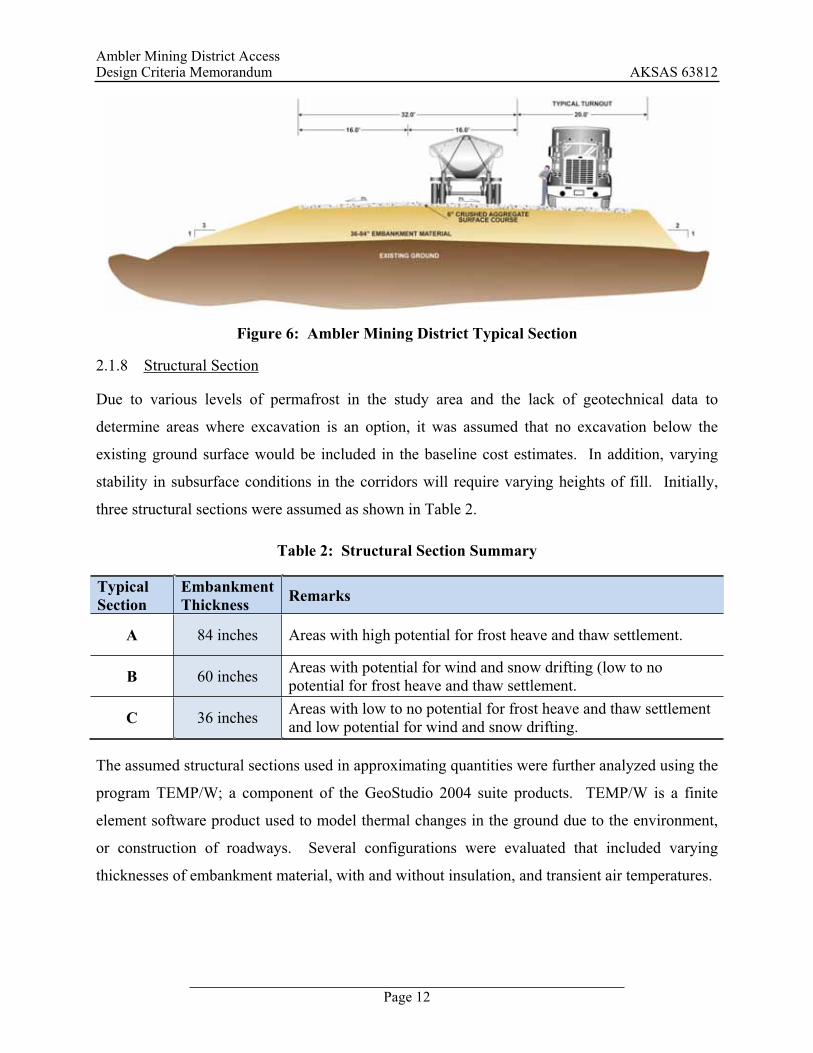
2.1.8 Structural Section
Due to various levels of permafrost in the study area and the lack of geotechnical data to
determine areas where excavation is an option, it was assumed that no excavation below the
existing ground surface would be included in the baseline cost estimates. In addition, varying
stability in subsurface conditions in the corridors will require varying heights of fill. Initially,
three structural sections were assumed as shown in Table 2.
Table 2: Structural Section Summary
TypicalSection
EmbankmentThickness Remarks
A 84 inches Areas with high potential for frost heave and thaw settlement.
B 60 inches Areas with potential for wind and snow drifting (low to no potential for frost heave and thaw settlement.
C 36 inches Areas with low to no potential for frost heave and thaw settlement and low potential for wind and snow drifting.
The assumed structural sections used in approximating quantities were further analyzed using the
program TEMP/W; a component of the GeoStudio 2004 suite products. TEMP/W is a finite
element software product used to model thermal changes in the ground due to the environment,
or construction of roadways. Several configurations were evaluated that included varying
thicknesses of embankment material, with and without insulation, and transient air temperatures.
Ambler Mining District Access Design Criteria Memorandum AKSAS 63812
Page 13
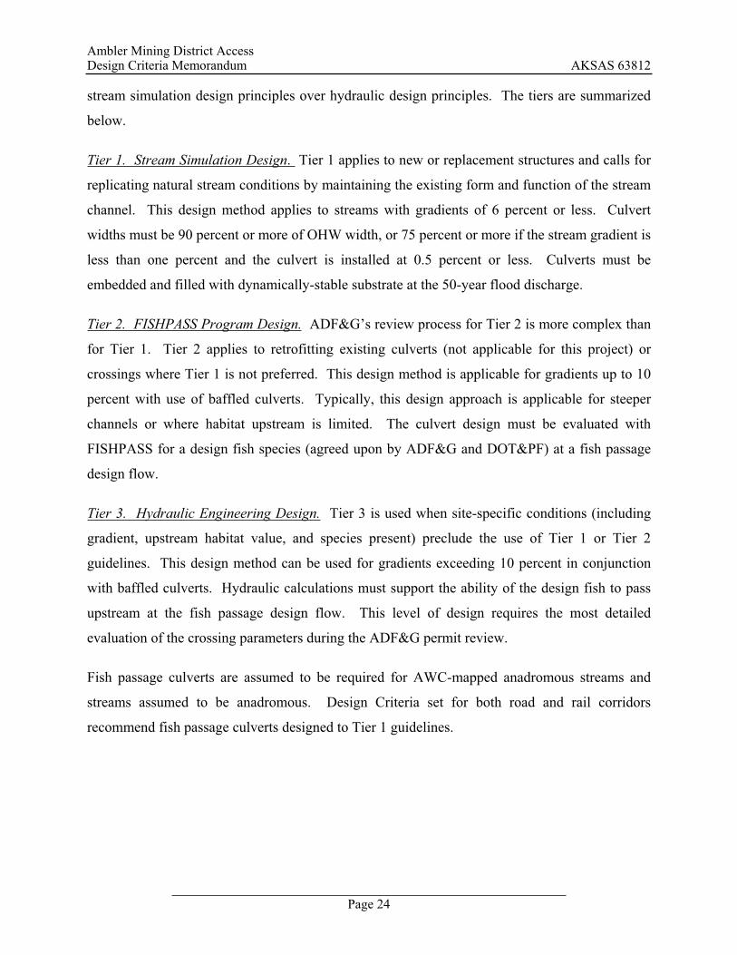
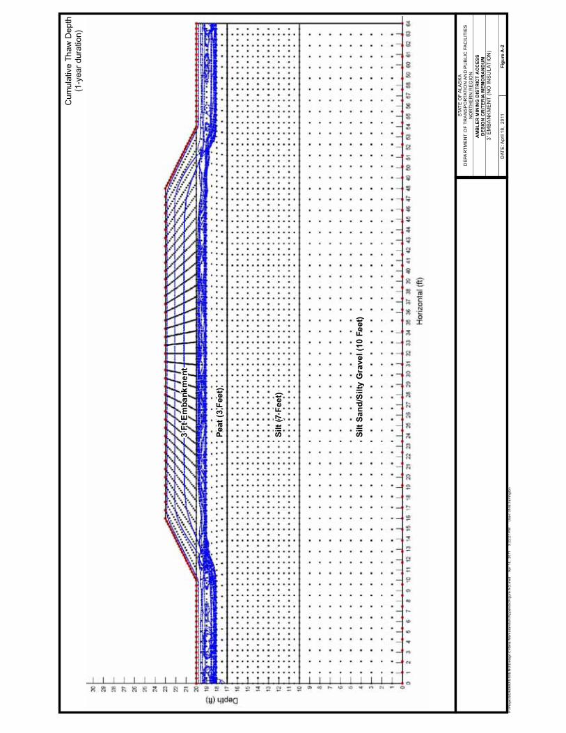
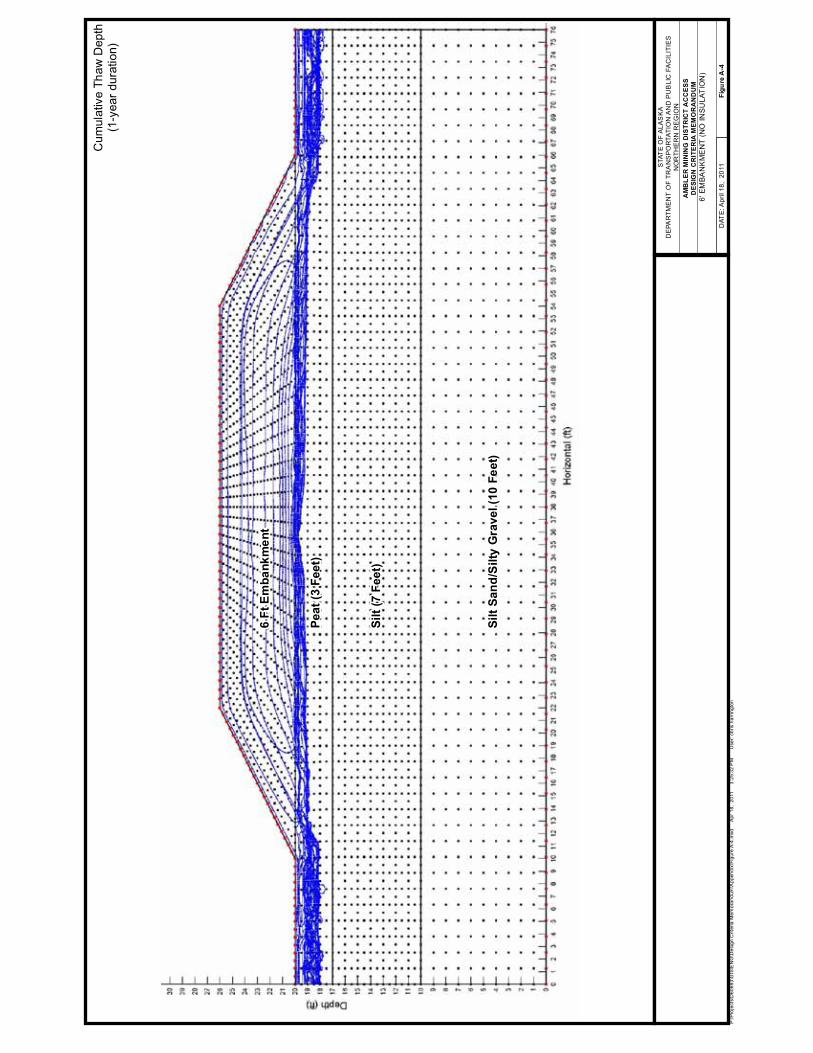
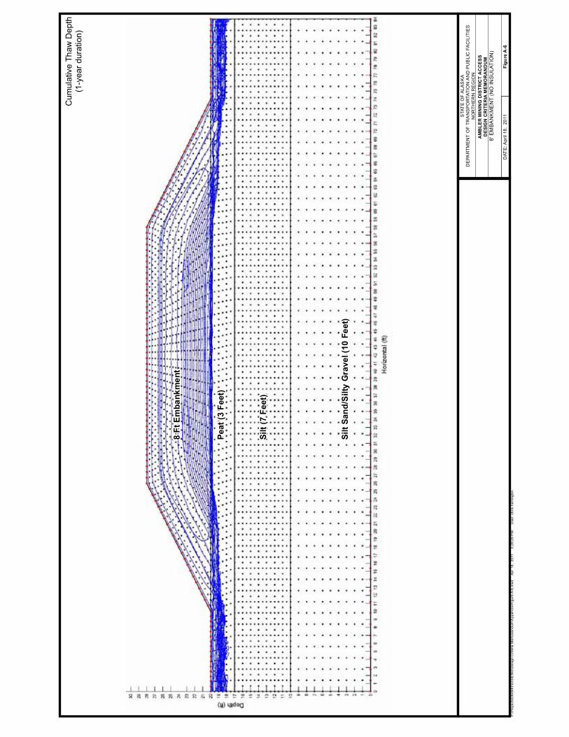
2.1.8.1 Thermal Modeling - Transient Analysis
The model assumes winter construction for fill placement, and models conditions for 9,000 hours
(approximately one year). The model ran thaw calculations at five-day increments (120 hours).
Each of the 75 calculations created under each model indicated depth of thaw (where occurring)
and a summary of the thaw depths over the model year is shown in Appendix A. Each blue line
shown represents depth of thaw during a 5-day increment.
2.1.8.2 Thermal Modeling - Corridor Soil Profile
Soil profiles within each corridor vary greatly. For this preliminary engineering effort, a generic
profile was created. The profile assumes four existing layers extending a total depth of 20 feet
below the original ground surface; a point at which it was assumed the soil temperatures would
remain constant year-round and maintain temperatures of 30 F below a depth of 20 feet for both
steady-state and transient heat flow analysis. The profile assumptions are:
Gravel fill material of varying depth, overlying
Three feet of peat, overlying
Seven feet of silt, overlying
Ten feet of silty sands and gravels.
After the initial analyses were completed, the soil profile was modified to observe the variation
in thaw depths. In one profile, the peat layer was decreased to one foot thick, increasing the silt
layer to nine feet. In a subsequent profile, the water content of the peat was decreased to indicate
drier conditions and a tendency for greater thaw depths.
2.1.8.3 Thermal Modeling - Air Temperature
TEMP/W allows the air temperature (surface boundary condition) to vary over time. Average
monthly temperatures were obtained from the Western Regional Climate Center for Bettles,
Alaska (see Appendix A).

Ambler Mining District Access Design Criteria Memorandum AKSAS 63812
Page 14
Average monthly temperatures were assigned to occur in the middle of the month. The model
calculated a temperature for each five-day time increment using the average monthly
temperatures.
2.1.8.4 Thermal Modeling - Thermal Properties of Soils
The thermal properties of the materials used in the model are critical to the analyses. Average
thermal properties for each material were assumed based on the general knowledge of soil
conditions within the corridors and published data. Table 3 details the material properties
assumed in the analysis.
Table 3: Assumed Thermal Properties of Materials
Material Name
FrozenThermal
Conductivity(BTU/ft/hr/F)
Unfrozen Thermal
Conductivity(BTU/ft/hr/F)
FrozenVolumetric
HeatCapacity
(BTU/ft3/F)
Unfrozen Volumetric
Heat Capacity (BTU/ft3/F)
Volumetric Water
Content %
Organic, Wet Peat 1.05 0.2 30 55 2.1 Silt 1.04 0.81 29.6 43.5 0.93 Silty Sand w/Gravel 1.27 1.04 26.4 32.4 0.66 Gravel Fill 1.25 1.15 25 28.8 0.13 Insulation 0.02 0.02 3 3 0
2.1.8.5 Thermal Modeling - Boundary Conditions
The model uses boundary conditions to control external forces that enter and leave the model
area. For 2D models typically upper and lower boundary conditions are assumed. The upper
boundary was assumed to be the ground surface and would be controlled by air temperatures.
TEMP/W allows the air temperature to vary over time.
The lower boundary layer for soil models is generally the depth at which the ground
temperatures are constant and unaffected by seasonal air temperatures. We assumed the soil
temperatures remained constant 20 feet below the existing surface at 30 F.
2.1.8.6 Thermal Modeling - Analysis
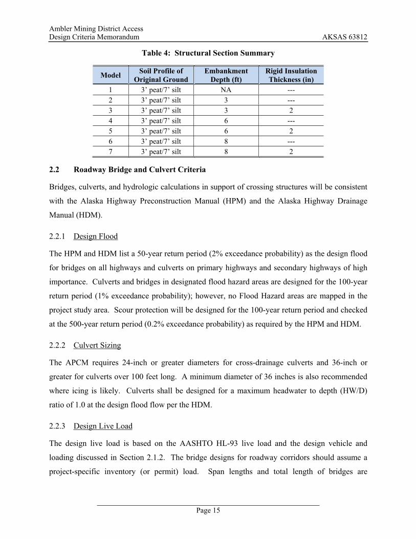
Seven different analyses were completed and are outlined in Table 4. These analyses were used
to develop the proposed structural section details. For each of the analyses, a summary of the
thaw depths that occurred over a 1-year duration is shown in Appendix A.
Ambler Mining District Access Design Criteria Memorandum AKSAS 63812
Page 15
Table 4: Structural Section Summary
Model Soil Profile of Original Ground
Embankment Depth (ft)
Rigid Insulation Thickness (in)
1 3’ peat/7’ silt NA --- 2 3’ peat/7’ silt 3 --- 3 3’ peat/7’ silt 3 2 4 3’ peat/7’ silt 6 --- 5 3’ peat/7’ silt 6 2 6 3’ peat/7’ silt 8 --- 7 3’ peat/7’ silt 8 2
2.2 Roadway Bridge and Culvert Criteria
Bridges, culverts, and hydrologic calculations in support of crossing structures will be consistent
with the Alaska Highway Preconstruction Manual (HPM) and the Alaska Highway Drainage
Manual (HDM).
2.2.1 Design Flood
The HPM and HDM list a 50-year return period (2% exceedance probability) as the design flood
for bridges on all highways and culverts on primary highways and secondary highways of high
importance. Culverts and bridges in designated flood hazard areas are designed for the 100-year
return period (1% exceedance probability); however, no Flood Hazard areas are mapped in the
project study area. Scour protection will be designed for the 100-year return period and checked
at the 500-year return period (0.2% exceedance probability) as required by the HPM and HDM.
2.2.2 Culvert Sizing
The APCM requires 24-inch or greater diameters for cross-drainage culverts and 36-inch or
greater for culverts over 100 feet long. A minimum diameter of 36 inches is also recommended
where icing is likely. Culverts shall be designed for a maximum headwater to depth (HW/D)
ratio of 1.0 at the design flood flow per the HDM.
2.2.3 Design Live Load
The design live load is based on the AASHTO HL-93 live load and the design vehicle and
loading discussed in Section 2.1.2. The bridge designs for roadway corridors should assume a
project-specific inventory (or permit) load. Span lengths and total length of bridges are
Ambler Mining District Access Design Criteria Memorandum AKSAS 63812
Page 16
important parameters in evaluating capacity to support inventory loading. Shorter bridge spans
may carry only part of the total load at any one time, whereas longer bridge spans carry the entire
load at once; thus, gross vehicle weight and geometry must be considered. Regardless of gross
weight, load geometry is critical for completing any analysis and or design. DOT&PF’s bridge
design group recommended evaluating bridges for an inventory load multiplied by a 1.35 load
factor (verbal communication, Elmer Marx, DOT&PF). In the absence of a specific inventory
load, or as a comparison to the inventory load, the HL-93 loading multiplied by a 1.75 load
factor could be used in evaluating any bridge of any size (verbal communication, Elmer Marx,
DOT&PF). Bridges should be designed for whichever load is greater.
3.0 RAILWAY DESIGN CRITERIA
3.1 General Criteria
The railway design criteria for the Ambler Mining District Access were developed from three
primary sources: the Alaska Railroad Corporation (ARRC), the American Railway Engineering
and Maintenance-of-way Association (AREMA), and the Federal Railroad Administration
(FRA). If a rail option is selected by DOT&PF as the preferred corridor, it is unknown who will
own, maintain, and operate the rail facilities. In the absence of any other criteria, the evaluation
of the rail alignment is based primarily on ARRC design standards because ARRC has
specialized experience in design, operation, construction, and maintenance of railroad facilities
in Alaska. ARRC assets include track, bridges, signalization equipment, maintenance facilities,
loading/unloading equipment, locomotives, and a fleet of railcars. Additionally, the State of
Alaska owns the ARRC. For criteria that ARRC guidelines do not address, AREMA guidelines
may apply. The ARRC uses AREMA’s recommended practices as a foundation for their design
standards, similar to large North American Class I Railroad companies (Class I railroad
companies have operating revenues in excess of $346.8 million). A summary of the initial
design criteria appears in Table 5.

Ambler Mining District Access Design Criteria Memorandum AKSAS 63812
Page 17
Table 5: Initial Railway Design Criteria
Element This Project Criteria Source/Rationale Project Type New construction Scope of services Track Classification Class 3, non-mainline FRA Federal Track Safety Standards Freight Car Weight 286,000-lb (143 tons) rail cars North American heavy-rail standard
Annual Tonnage Less than 10,000,000 gross tons
Assume less than 700 trains annually, or 1.92 trains daily, see Section 3.1.1.
Maximum Design Speed 40 mph for freight traffic FRA Class 3 Track; see Section 3.1.2.
Grade Limitations Level, 0-0.5% Rolling, 0.5-1.0% Mountainous, 1.0-1.5%
ARRC standard practice
Track Components 141RE Continuously Welded RailARRC Standard Concrete Ties
ARRC standard practice for new construction ARRC Standard Drawing 1.4-05
Track Section
Structural Section
Subballast
Embankment in permafrost areas
Embankment in non-permafrost areas
Rail, Ties, Ballast
48-inch or 84-inch total section, ballast not included
12 inches Aggregate Base Course Grading C-1
36 inches Selected Material Type A 36 inches Compacted Embankment (Selected Material Type C or better)
36 inches Selected Material Type A
ARRC Standard Drawings 2.3-03 and 2.1-04
ADOT&PF Standard Specifications for Highway Construction
Type A requirement from recent ARRC projects
Siding Tracks
Length: approximately 8,500’ (8,000’ clear length) Spacing: 15’ between track centerlines Longitudinal Spacing: approximately every 20 miles #15 Turnouts (hand-thrown)
ARRC standard practice for new construction; see Section 3.1.4. ARRC Standard Drawing 2.11-05 ARRC standard practice for new construction; see Section 3.1.4. ARRC standard practice for new construction; assume non-electrified track, see Section 3.1.4.
Maximum Degree of Curvature
6o (Radius = 955.36’), Chord Defined 5o (Radius = 1146.28’) preferred
AREMA Manual for Railway Engineering ARRC Track Chart
Superelevation
Maximum: 4.75 inches (6o
curve)Preferred: 3.75 inches (5o
curve)Unbalance: 2 inches
ARRC Track Chart FRA Federal Track Safety Standards
Fish Passage Tier 1. Stream Simulation Design
2001 Memorandum of Understanding (MOU) between ADF&G and DOT&PF for the Design, Permitting, and Construction of Culverts for Fish Passage
Bridge Loading Cooper E-80 AREMA Manual for Railway Engineering

Ambler Mining District Access Design Criteria Memorandum AKSAS 63812
Page 18
3.1.1 Classification and Estimated Traffic
The track classification for a railroad line into the Ambler mineral belt will depend on several
factors; ultimately, the classification dictates the design speed and maintenance requirements of
the track. The FRA establishes track classes with progressively increasing standards for track
quality and inspection timelines.
Table 6: FRA Classes of Railroad Track
Class of Track
Maximum Speed, Freight Traffic
Maximum Speed, Passenger Traffic
Minimum Track Inspection Frequency
Class 1* 10 mph 15 mph Non-mainline: Monthly Mainline: twice weekly Class 2* 25 mph 30 mph
Class 3* 40 mph 60 mph
Class 4 60 mph 80 mph
Twice weekly Class 5 80 mph 90 mph Class 6 NA 110 mph
Class 7 NA 125 mph
Class 8 NA 150 mph
Class 9 NA 200 mph Three times weekly * Note: for Classes 1 through 3, track is considered mainline if it carries passenger traffic or more than
10 million gross tons during the preceding year.
As shown in Table 6, track with a higher classification can travel at greater speeds, but the
inspection requirements become more rigid. Railroad companies determine their own class of
track based on FRA guidelines for track structure, track geometry, and the FRA enforces
maintenance standards for the specified track classification. Track structure refers to rails,
crossties, track switches, tie plates, and rail fastening systems. Track geometry is the gage (the
distance between individual rails), alignment, super-elevation, and curvature. If any of these
structure or geometric elements are inadequate, or if track maintenance is inadequate, then the
track classification must be downgraded, thus reducing the allowable track speed.
Class 3 (non-mainline) track is recommended for access to the Ambler mineral belt. This
classification allows reduced maintenance costs by requiring monthly track inspections rather
than twice-weekly inspections.
Ambler Mining District Access Design Criteria Memorandum AKSAS 63812
Page 19
The non-mainline designation is dependent upon the annual tonnage hauled over the rail line.
The assumed traffic carried by the track will be less than 10 million gross tons annually. Since
the primary purpose for constructing a rail line to the Ambler mineral belt is for hauling bulk
commodities, resources extracted from the Ambler area will likely be hauled away on unit trains.
All rail cars in a “unit train” have the same point of origin and the same destination. Unit trains
do not need to be divided and reclassified in rail yards, thus improving operational efficiency and
reducing costs. Unit trains typically carry only one commodity and therefore consist of the same
type of rail cars. Across North America, unit trains typically consist of approximately 100 rail
cars, and the maximum weight of each car is 286,000 pounds (143 tons) each. Therefore, the
non-mainline threshold of 10 million tons equates to 700 unit trains annually or 1.92 unit trains
daily. As a comparison, the 2008 production from Red Dog mine was 703,289 tons (567,911
tons of zinc and 135,144 tons of lead, and 234 tons of silver), which would require only 49 unit
trains.
3.1.2 Design Speed
Freight traffic and passenger traffic can travel at different speeds over the same track. However,
for the purposes of accessing the Ambler mineral belt, freight guidelines are more economically
feasible and meets the project objective to haul bulk commodities from the Ambler mineral belt.
Freight traffic on FRA Class 3 track (non-mainline) can travel at 40 mph, which is appropriate
since time-sensitive intermodal traffic is not expected. In addition, this speed is commonly used
for regional railroads and secondary mainlines for large Class I railroad companies.
3.1.3 Grade Limitations
ARRC prefers grades between 0 and 0.50% to maximize operational efficiency. ARRC accepts
grades of 0.50-1.00%, but these should be limited to the extent possible. Grades of 1.00-1.50%
are not advisable for the heavy loads expected from the Ambler mineral belt and, if ARRC were
to own/operate the track, would require approval from the ARRC Chief Engineer.
3.1.4 Typical Section
The track structure consists of a minimum of 1-foot (minimum) of ballast below the base of
concrete ties and 141-lb RE continuously-welded rail. “RE” denotes an AREMA standard rail

Ambler Mining District Access Design Criteria Memorandum AKSAS 63812
Page 20
section, see Figure 7. Continuously-welded rail (CWR) is manufactured in 39-foot lengths,
which can be welded into lengths up to 1,600 feet long for construction. This is consistent with
ARRC’s standard practices for new track construction elsewhere in Alaska.
Figure 7: 141-lb RE Rail Section
Using other lower-quality track components could reduce construction costs, but other costs may
increase as a result. 115-lb. rail is less expensive, but will experience more wear than 141-lb.
rail. Additionally, substituting CWR for jointed rail could reduce construction costs, but the
maintenance costs are higher. Similarly, wooden ties are cheaper than concrete ties, but they
also require more maintenance and have a shorter lifespan. Another consideration is that the use
of lower-quality materials may reduce the overall stiffness of the track structure. Significant
reductions in stiffness could require a thicker subgrade section, enhanced subgrade preparation,
reduced tie spacing (and therefore more ties), and increased maintenance or inspection
requirements, but these items should be evaluated during future design tasks.

Ambler Mining District Access Design Criteria Memorandum AKSAS 63812
Page 21
Two different track embankment sections were evaluated: one for use when information
indicates the presence of wetlands, and one for locations without wetlands. The bottom portion
of the typical section in wetlands areas consists of 36-inches of compacted embankment material
meeting a minimum quality standard comparable to Selected Material Type C (note: ARRC uses
DOT&PF material specifications because it does not have specifications for non-rail elements).
Above this layer is a 36-inch layer of Selected Material Type A. This is consistent with the
thermal modeling for the roadway. A 12-inch layer of subballast lies directly above the Select
Material Type A (see Figure 8). Subballast should meet specifications for Aggregate Base
Course Grading C-1. This embankment is consistent with new construction practices for the
ARRC in wetland areas, but the project geotechnical engineer should reevaluate the material
type, depth, and availability during the design phase of the project. Railroad embankments may
have higher compaction required than roadway embankments; again, this should be confirmed
with the project geotechnical engineer during the design phase.
In areas that do not contain wetlands, the 36-inch layer of Selected Material, Type A can be
placed directly upon an adequately prepared subgrade, followed by 12 inches of subballast.
Figure 8: Railway Mainline Typical Section
To facilitate railroad operations, the Ambler mineral belt corridor incorporates a series of siding
tracks. Separated from the main line, siding tracks generally serve an auxiliary purpose, such as
loading, unloading, passing, and staging or storing rail cars while traffic continues using the
primary track. For new routes that anticipate having two trains daily and the potential for

Ambler Mining District Access Design Criteria Memorandum AKSAS 63812
Page 22
additional future trains, ARRC plans to have sidings at 10-mile intervals. Due to the lower
traffic volume expected along the Ambler mineral belt corridor, sidings are suitable at 20-mile
intervals; however, designers should accommodate additional future sidings during the design
phase. Each siding will require a #15 turnout at each end of the siding to allow trains to pass
from the mainline to the siding. The turnouts along the Ambler mineral belt corridor are hand-
thrown, meaning the train operator must exit the train and operate the switch in order to occupy
the siding track. Electric switches would not be practical along this corridor due to the low
volume of traffic and the lack of other signalization requirements along the corridor. The ARRC
guideline for the spacing between the centerline of the siding and the centerline of the main line
is 15 feet see Figure 8. Sidings 8,500 feet long have over, 8,000 feet of track at the full 15-foot
separation. This length can easily accommodate a unit train consisting of 100 “hopper” rail cars
filled with bulk commodities, or a unit train hauling roughly 80 flat cars (flat cars are generally
longer than hopper cars).
Figure 9: Railroad Typical Section with Siding Track
3.1.5 Geometric Criteria
The geometric criteria are based on the design speed of the track. The maximum degree of
curvature for a 40 mph design speed is 6 degrees, but this requires 4.75 inches of superelevation.
The minimum radius of a 6-degree curve is 955.36 feet. (note: that curves in railroad alignments
use the chord definition, not the arc definition used in roadway design. By comparison, an arc-
defined 6-degree curve has a radius of 954.93 feet). In addition, the 4.75-inch superelevation
mentioned above is not the equilibrium elevation. Rather, ARRC unbalances the equilibrium
Ambler Mining District Access Design Criteria Memorandum AKSAS 63812
Page 23
elevation by 2 inches to reduce the wear on the inside rail when train speeds are less than the
design speed. Minimizing the number of curves and maximizing the degree of curvature when
possible will also reduce wearing on rails and extend the life of the track.
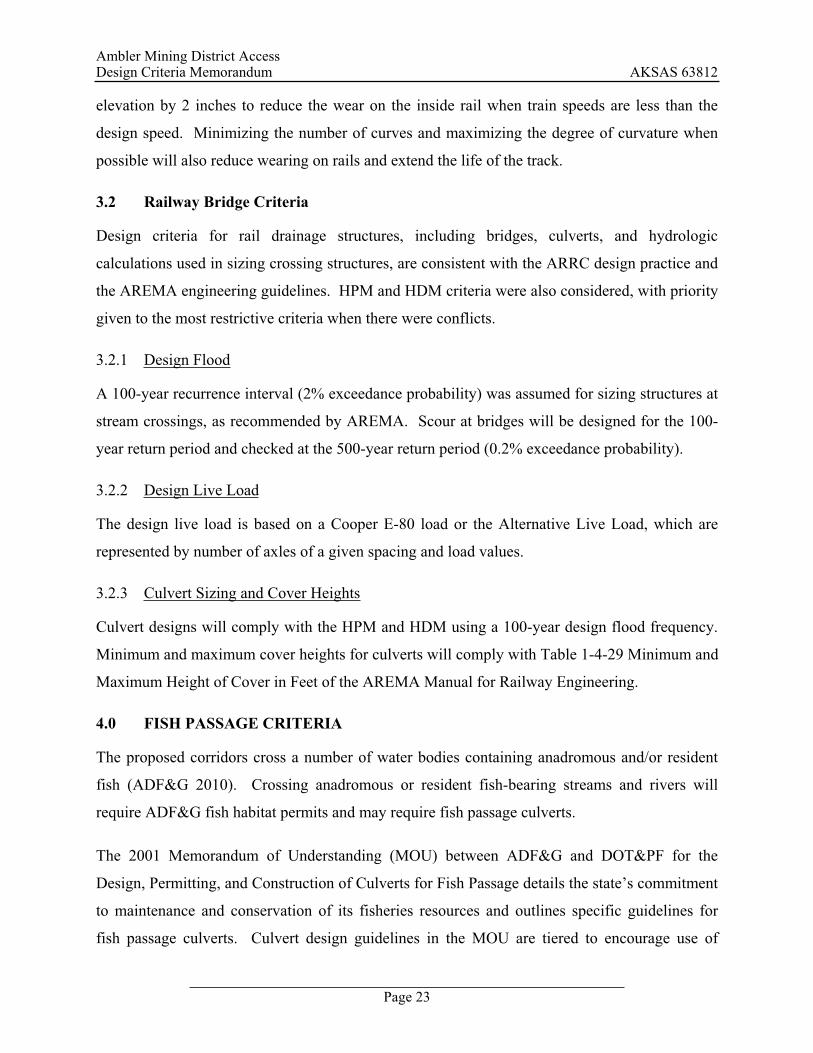
3.2 Railway Bridge Criteria
Design criteria for rail drainage structures, including bridges, culverts, and hydrologic
calculations used in sizing crossing structures, are consistent with the ARRC design practice and
the AREMA engineering guidelines. HPM and HDM criteria were also considered, with priority
given to the most restrictive criteria when there were conflicts.
3.2.1 Design Flood
A 100-year recurrence interval (2% exceedance probability) was assumed for sizing structures at
stream crossings, as recommended by AREMA. Scour at bridges will be designed for the 100-
year return period and checked at the 500-year return period (0.2% exceedance probability).
3.2.2 Design Live Load
The design live load is based on a Cooper E-80 load or the Alternative Live Load, which are
represented by number of axles of a given spacing and load values.
3.2.3 Culvert Sizing and Cover Heights
Culvert designs will comply with the HPM and HDM using a 100-year design flood frequency.
Minimum and maximum cover heights for culverts will comply with Table 1-4-29 Minimum and
Maximum Height of Cover in Feet of the AREMA Manual for Railway Engineering.
4.0 FISH PASSAGE CRITERIA
The proposed corridors cross a number of water bodies containing anadromous and/or resident
fish (ADF&G 2010). Crossing anadromous or resident fish-bearing streams and rivers will
require ADF&G fish habitat permits and may require fish passage culverts.
The 2001 Memorandum of Understanding (MOU) between ADF&G and DOT&PF for the
Design, Permitting, and Construction of Culverts for Fish Passage details the state’s commitment
to maintenance and conservation of its fisheries resources and outlines specific guidelines for
fish passage culverts. Culvert design guidelines in the MOU are tiered to encourage use of
Ambler Mining District Access Design Criteria Memorandum AKSAS 63812
Page 24
stream simulation design principles over hydraulic design principles. The tiers are summarized
below.
Tier 1. Stream Simulation Design. Tier 1 applies to new or replacement structures and calls for
replicating natural stream conditions by maintaining the existing form and function of the stream
channel. This design method applies to streams with gradients of 6 percent or less. Culvert
widths must be 90 percent or more of OHW width, or 75 percent or more if the stream gradient is
less than one percent and the culvert is installed at 0.5 percent or less. Culverts must be
embedded and filled with dynamically-stable substrate at the 50-year flood discharge.
Tier 2. FISHPASS Program Design. ADF&G’s review process for Tier 2 is more complex than
for Tier 1. Tier 2 applies to retrofitting existing culverts (not applicable for this project) or
crossings where Tier 1 is not preferred. This design method is applicable for gradients up to 10
percent with use of baffled culverts. Typically, this design approach is applicable for steeper
channels or where habitat upstream is limited. The culvert design must be evaluated with
FISHPASS for a design fish species (agreed upon by ADF&G and DOT&PF) at a fish passage
design flow.
Tier 3. Hydraulic Engineering Design. Tier 3 is used when site-specific conditions (including
gradient, upstream habitat value, and species present) preclude the use of Tier 1 or Tier 2
guidelines. This design method can be used for gradients exceeding 10 percent in conjunction
with baffled culverts. Hydraulic calculations must support the ability of the design fish to pass
upstream at the fish passage design flow. This level of design requires the most detailed
evaluation of the crossing parameters during the ADF&G permit review.
Fish passage culverts are assumed to be required for AWC-mapped anadromous streams and
streams assumed to be anadromous. Design Criteria set for both road and rail corridors
recommend fish passage culverts designed to Tier 1 guidelines.

Ambler Mining District Access Design Criteria Memorandum AKSAS 63812
Page 25
5.0 REFERENCES
State of Alaska Department of Transportation & Public Facilities (DOT&PF) 2004. StandardSpecifications for Highway Construction. Juneau, AK.
State of Alaska Department of Transportation and Public Facilities (DOT&PF) 2010. NorthernRegion Annual Traffic Volume Report. DOT&PF Northern Region.
State of Alaska Department of Transportation and Public Facilities (DOT&PF) 1995. AlaskaHighway Drainage Manual.
State of Alaska Department of Transportation and Public Facilities (DOT&PF) 1995. AlaskaHighway Preconstruction Manual.
Alaska Railroad Corporation (ARRC) 2009. Standard Plans, Ballast and Track Work, Standard Drawings 1.4-05, 2.1-04, 2.11-05, 2.3-03. Anchorage, AK.
Alaska Railroad Corporation (ARRC), 2010. Track Chart. Anchorage, AK.
American Association of State Highway and Transportation Officials (AASHTO) 2001.Guidelines for Geometric Design of Very Low-volume Local Roads (ADT 400).
American Association of State Highway and Transportation Officials (AASHTO) 2004. A Policy on Geometric Design of Highways and Streets, 5th Edition.
American Railway Engineering and Maintenance-of-Way Association (AREMA) 2010. Manual for Railway Engineering. Lanham, MD.
Federal Railroad Administration (FRA) 2002, 2007 & 2008 Revision. Track Safety Standards Compliance Manual. Available on-line at http://www.fra.dot.gov/Pages/460.shtml.
Federal Railroad Administration (FRA) 2008. Federal Track Safety Standards Fact Sheet.Available on-line at http://www.fra.dot.gov/downloads/PubAffairs/Track%20Standards%20fact%20sheet%20FINAL.pdf.
Goldhofer. Modular Trailers. Available on-line at http://www.goldhofer.de/gh-en/modular-vehicles/introduction-to-the-technology.php
Harmer Steel, 2010. 141-lb. AREMA. Available on-line at http://www.harmersteel.com/ catalog/tee-rails/141-lbyd-arema-rail/.
DOWL HKM 2010. Western Alaska Access Planning Study, Corridor Planning Report, prepared for the State of Alaska Department of Transportation and Public Facilities.
National Corrugated Steel Pipe Association. 2008. Corrugated Steel Pipe Design Manual.Dallas, TX.
Szumigala, D.J., Hughes, R.A., and Harbo, L.A., 2009. Information Circular 58, Alaska’s Mineral Industry 2008: A Summary. Alaska Division of Geological & Geophysical Surveys, Fairbanks, AK.
Western Region Climate Center. Bettles FAA Airport, Alaska. Available on-line at http://www.wrcc.dri.edu/cgi-bin/cliMAIN.pl?akbett

APPENDIX A
Thermal Modeling-Thaw Depth Figures

Back to:
NOTE:To print data frame (right side), click on right frame before printing.
1971 - 2000
Daily Temp. & Precip. Daily Tabular data (~23 KB)Monthly Tabular data (~1 KB)NCDC 1971-2000 Normals (~3
KB)
1961 - 1990
Daily Temp. & Precip. Daily Tabular data (~23 KB)Monthly Tabular data (~1 KB)NCDC 1961-1990 Normals (~3
KB)
Period of Record
Station Metadata Station Metadata Graphics
General Climate Summary Tables
TemperaturePrecipitationHeating Degree DaysCooling Degree DaysGrowing Degree Days
TemperatureDaily Extremes and Averages Spring 'Freeze' Probabilities Fall 'Freeze' Probabilities 'Freeze Free' Probabilities Monthly Temperature Listings
AverageAverage MaximumAverage Minimum
Precipitation Monthly Average Daily Extreme and Average Daily Average
BETTLES FAA AIRPORT, ALASKA
Period of Record General Climate Summary - Temperature
Station:(500761) BETTLFrom Year=1951 T
MonthlyAverages Daily Extremes
Max. Min. Mean High Date Low Date
F F F Fdd/yyyy
oryyyymmdd
Fdd/yyy
oryyyymm
January -4.3 -20.2 -12.1 48 01/1980 -70 04/19
February 1.7 -16.7 -7.5 40 21/1977 -64 09/19
March 14.9 -8.8 3.0 49 22/1998 -56 14/19
April 32.5 10.1 21.3 63 30/1995 -37 07/19
May 53.1 33.5 43.3 86 31/1983 -10 03/19
June 68.3 46.9 57.6 92 16/1969 27 01/19
July 69.4 48.8 59.1 93 06/1986 29 14/19
August 62.4 43.5 52.9 88 06/1994 22 30/19
September 48.4 32.1 40.3 79 05/1957 0 23/19
October 25.4 12.4 19.0 57 02/2003 -35 31/19
November 5.9 -8.1 -1.1 45 13/1976 -57 25/19
December -1.4 -16.5 -9.0 38 09/1960 -59 25/19
Annual 31.4 13.1 22.2 93 19860706 -70 197501
Winter -1.3 -17.8 -9.5 48 19800101 -70 197501
Spring 33.5 11.6 22.5 86 19830531 -56 196403
Summer 66.7 46.4 56.5 93 19860706 22 196808
Fall 26.6 12.1 19.4 79 19570905 -57 197411
Page 1 of 1BETTLES FAA AIRPORT, ALASKA - Climate Summary
4/18/2011http://www.wrcc.dri.edu/cgi-bin/cliMAIN.pl?akbett

P:\P
roje
cts\
D60
693\
GIS
\EN
G\D
esig
nC
riter
iaM
emor
andu
m\A
ppen
dix\
Figu
reA
-1.m
xdA
pr18
,20
113:
01:1
5P
MU
ser:
chris
.har
ringt
on
STA
TE
OF
ALA
SK
AD
EPA
RTM
EN
TO
FTR
AN
SP
OR
TATI
ON
AN
DP
UB
LIC
FAC
ILIT
IES
NO
RTH
ER
NR
EG
ION
AM
BLE
RM
ININ
GD
ISTR
ICT
AC
CES
SD
ESIG
NC
RIT
ERIA
MEM
OR
AN
DU
ME
XIS
TIN
GC
ON
DIT
ION
S
DAT
E:A
pril
18,
2011
Figu
reA
-1
Cum
ulat
ive
Thaw
Dep
th(1
-yea
rdur
atio
n)
Silt
Sand
/Silt
yG
rave
l(10
Feet
)
Silt
(7Fe
et)
Peat
(3Fe
et)
P:\P
roje
cts\
D60
693\
GIS
\EN
G\D
esig
nC
riter
iaM
emor
andu
m\A
ppen
dix\
Figu
reA
-2.m
xdA
pr18
,20
113:
22:2
7P
MU
ser:
chris
.har
ringt
on
Figu
reA
-2
Cum
ulat
ive
Thaw
Dep
th(1
-yea
rdur
atio
n)
STA
TE
OF
ALA
SK
AD
EPA
RTM
EN
TO
FTR
AN
SP
OR
TATI
ON
AN
DP
UB
LIC
FAC
ILIT
IES
NO
RTH
ER
NR
EG
ION
AM
BLE
RM
ININ
GD
ISTR
ICT
AC
CES
SD
ESIG
NC
RIT
ERIA
MEM
OR
AN
DU
M3'
EM
BA
NK
ME
NT
(NO
INS
ULA
TIO
N)
DAT
E:A
pril
18,
2011
Silt
(7Fe
et)
Peat
(3Fe
et)
Silt
Sand
/Silt
yG
rave
l(10
Feet
)
3Ft
Emba
nkm
ent
P:\P
roje
cts\
D60
693\
GIS
\EN
G\D
esig
nC
riter
iaM
emor
andu
m\A
ppen
dix\
Figu
reA
-3.m
xdA
pr18
,20
113:
22:2
2P
MU
ser:
chris
.har
ringt
on
STA
TE
OF
ALA
SK
AD
EPA
RTM
EN
TO
FTR
AN
SP
OR
TATI
ON
AN
DP
UB
LIC
FAC
ILIT
IES
NO
RTH
ER
NR
EG
ION
AM
BLE
RM
ININ
GD
ISTR
ICT
AC
CES
SD
ESIG
NC
RIT
ERIA
MEM
OR
AN
DU
M3'
EM
BA
NK
ME
NT
(WIT
H2"
INS
ULA
TIO
N)
DAT
E:A
pril
18,
2011
Figu
reA
-3
Cum
ulat
ive
Thaw
Dep
th(1
-yea
rdur
atio
n)
Silt
(7Fe
et)
Peat
(3Fe
et)
Silt
Sand
/Silt
yG
rave
l(10
Feet
)
3Ft
Emba
nkm
ent
2"In
sula
tion
P:\P
roje
cts\
D60
693\
GIS
\EN
G\D
esig
nC
riter
iaM
emor
andu
m\A
ppen
dix\
Figu
reA
-4.m
xdA
pr18
,20
113:
25:3
2P
MU
ser:
chris
.har
ringt
on
Figu
reA
-4
Cum
ulat
ive
Thaw
Dep
th(1
-yea
rdur
atio
n)
STA
TE
OF
ALA
SK
AD
EPA
RTM
EN
TO
FTR
AN
SP
OR
TATI
ON
AN
DP
UB
LIC
FAC
ILIT
IES
NO
RTH
ER
NR
EG
ION
AM
BLE
RM
ININ
GD
ISTR
ICT
AC
CES
SD
ESIG
NC
RIT
ERIA
MEM
OR
AN
DU
M6'
EM
BA
NK
ME
NT
(NO
INS
ULA
TIO
N)
DAT
E:A
pril
18,
2011
Silt
(7Fe
et)
Peat
(3Fe
et)
Silt
Sand
/Silt
yG
rave
l(10
Feet
)
6Ft
Emba
nkm
ent

P:\P
roje
cts\
D60
693\
GIS
\EN
G\D
esig
nC
riter
iaM
emor
andu
m\A
ppen
dix\
Figu
reA
-5.m
xdA
pr18
,20
113:
25:2
7P
MU
ser:
chris
.har
ringt
on
STA
TE
OF
ALA
SK
AD
EPA
RTM
EN
TO
FTR
AN
SP
OR
TATI
ON
AN
DP
UB
LIC
FAC
ILIT
IES
NO
RTH
ER
NR
EG
ION
AM
BLE
RM
ININ
GD
ISTR
ICT
AC
CES
SD
ESIG
NC
RIT
ERIA
MEM
OR
AN
DU
M6'
EM
BA
NK
ME
NT
(WIT
H2"
INS
ULA
TIO
N)
DAT
E:A
pril
18,
2011
Figu
reA
-5
Cum
ulat
ive
Thaw
Dep
th(1
-yea
rdur
atio
n)
Silt
(7Fe
et)
Peat
(3Fe
et)
Silt
Sand
/Silt
yG
rave
l(10
Feet
)
6Ft
Emba
nkm
ent
2"In
sula
tion
P:\P
roje
cts\
D60
693\
GIS
\EN
G\D
esig
nC
riter
iaM
emor
andu
m\A
ppen
dix\
Figu
reA
-6.m
xdA
pr18
,20
113:
28:2
8P
MU
ser:
chris
.har
ringt
on
Figu
reA
-6
STA
TE
OF
ALA
SK
AD
EPA
RTM
EN
TO
FTR
AN
SP
OR
TATI
ON
AN
DP
UB
LIC
FAC
ILIT
IES
NO
RTH
ER
NR
EG
ION
AM
BLE
RM
ININ
GD
ISTR
ICT
AC
CES
SD
ESIG
NC
RIT
ERIA
MEM
OR
AN
DU
M8'
EM
BA
NK
ME
NT
(NO
INS
ULA
TIO
N)
DAT
E:A
pril
18,
2011
Cum
ulat
ive
Thaw
Dep
th(1
-yea
rdur
atio
n)
Silt
(7Fe
et)
Peat
(3Fe
et)
Silt
Sand
/Silt
yG
rave
l(10
Feet
)
8Ft
Emba
nkm
ent

P:\P
roje
cts\
D60
693\
GIS
\EN
G\D
esig
nC
riter
iaM
emor
andu
m\A
ppen
dix\
Figu
reA
-7.m
xdA
pr18
,20
113:
28:3
3P
MU
ser:
chris
.har
ringt
on
STA
TE
OF
ALA
SK
AD
EPA
RTM
EN
TO
FTR
AN
SP
OR
TATI
ON
AN
DP
UB
LIC
FAC
ILIT
IES
NO
RTH
ER
NR
EG
ION
AM
BLE
RM
ININ
GD
ISTR
ICT
AC
CES
SD
ESIG
NC
RIT
ERIA
MEM
OR
AN
DU
M8'
EM
BA
NK
ME
NT
(WIT
H2"
INS
ULA
TIO
N)
DAT
E:A
pril
18,
2011
Figu
reA
-7
Cum
ulat
ive
Thaw
Dep
th(1
-yea
rdur
atio
n)
Silt
(7Fe
et)
Peat
(3Fe
et)
Silt
Sand
/Silt
yG
rave
l(10
Feet
)
8Ft
Emba
nkm
ent
2"In
sula
tion

Ambler Mining District Access


