AMENDMENT No. 1 To AIS-068: Requirements for Windows Fitted on Buses 1. Page No. 3/17, cl. No. 5.1 Substitute following title for existing title: Static Strength Requirements: 2. Page No. 3/17, cl. No. 5.1.1 Substitute following text for existing text: “Windows, window frames and latching mechanism shall withstand peak force of 445 N to 534 N without damage when applied in all the three major axes, under simulated conditions where load shall be applied gradually.” 3. Page No. 3/17, after cl. No. 5.1.1 Add new clause 5.1.1.1 after existing clause 5.1.1 as follows: “5.1.1.1 The window manufacturer shall also specify on frame / glass the peak force which the window must be able to withstand without damage to the window, frame or latching mechanism.” 4. Page No. 3/17, cl. No. 5.1.2 Substitute following title for existing title: Durability Requirements 5. Page No. 3/17, cl. No. 5.1.2.2 Substitute following text for existing text: “It is recommended that the force required to open and close the windows be in the range of 50 N to 75 N ( 1 kg = 9.81 N) during durability requirements, which is representative of the force used by an individual to open and close.” 6. Page No. 3/17, cl. No. 5.1.2.3 Delete entire clause 5.1.2.3 1/2
Transcript
AMENDMENT No. 1
To
AIS-068: Requirements for Windows Fitted on Buses
1. Page No. 3/17, cl. No. 5.1
Substitute following title for existing title:
Static Strength Requirements:
2. Page No. 3/17, cl. No. 5.1.1
Substitute following text for existing text:
“Windows, window frames and latching mechanism shall withstand peak
force of 445 N to 534 N without damage when applied in all the three major
axes, under simulated conditions where load shall be applied gradually.”
3. Page No. 3/17, after cl. No. 5.1.1
Add new clause 5.1.1.1 after existing clause 5.1.1 as follows:
“5.1.1.1 The window manufacturer shall also specify on frame / glass the
peak force which the window must be able to withstand without damage to the
window, frame or latching mechanism.”
4. Page No. 3/17, cl. No. 5.1.2
Substitute following title for existing title:
Durability Requirements
5. Page No. 3/17, cl. No. 5.1.2.2
Substitute following text for existing text:
“It is recommended that the force required to open and close the windows be
in the range of 50 N to 75 N ( 1 kg = 9.81 N) during durability requirements,
which is representative of the force used by an individual to open and close.”
6. Page No. 3/17, cl. No. 5.1.2.3
Delete entire clause 5.1.2.3
1/2
7. Page No. 3/17, cl. No. 5.2
Substitute following text for existing text:
“Vibration Test: The window mounted on a suitable support shall be rigidly
fixed on a suitable vibrating machine constructed to produce simple harmonic
function ( a total amplitude of 0.35 mm ) and shall be subjected to vibration
through a frequency range of 10-55-10 Hz in a period of 1 minute with
continuously varying frequencies. The vibration shall be applied for not less
than 1 hour in the longitudinal and vertical axes of the vehicle on which the
window is fitted. At the end of the test the specimen window shall be
examined. During the examination, the window under test shall show no
evidence of material defects, breakage, displacement or rupture of the
assembly and the parts.
PRINTED BY
THE AUTOMOTIVE RESEARCH ASSOCIATION OF INDIA
P.B. NO. 832, PUNE 411 004
ON BEHALF OF
AUTOMOTIVE INDUSTRY STANDARDS COMMITTEE
UNDER
CENTRAL MOTOR VEHICLE RULES – TECHNICAL STANDING
COMMITTEE
SET-UP BY
MINISTRY OF ROAD TRANSPORT & HIGHWAYS
(DEPARTMENT OF ROAD TRANSPORT & HIGHWAYS)
GOVERNMENT OF INDIA
December 2009
2/2
AIS-068
AUTOMOTIVE INDUSTRY STANDARDS
Requirements for
Windows fitted on Buses
PRINTED BY THE AUTOMOTIVE RESEARCH ASSOCIATION OF INDIA
P.B. NO. 832, PUNE 411 004
ON BEHALF OF AUTOMOTIVE INDUSTRY STANDARDS COMMITTEE
UNDER
CENTRAL MOTOR VEHICLE RULES – TECHNICAL STANDING COMMITTEE
SET-UP BY MINISTRY OF SHIPPING, ROAD TRANSPORT & HIGHWAYS
(DEPARTMENT OF ROAD TRANSPORT & HIGHWAYS) GOVERNMENT OF INDIA
December 2005
I
AIS-068
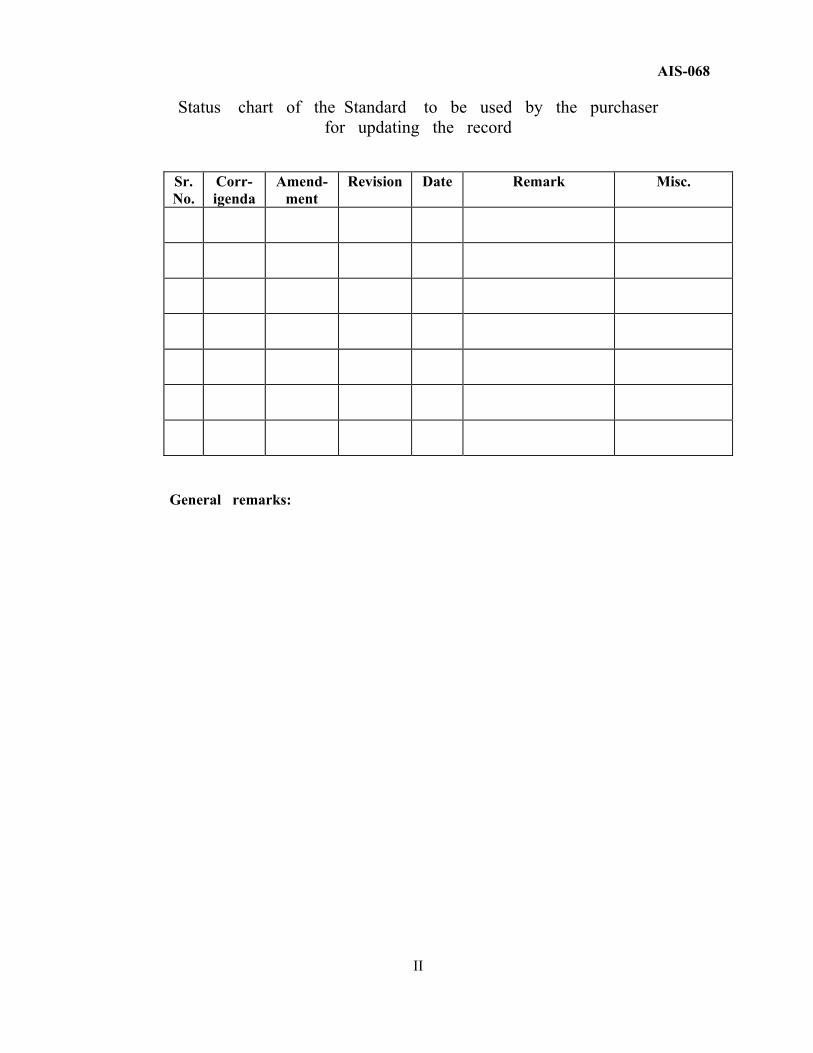
Status chart of the Standard to be used by the purchaser
for updating the record Sr. No.
Corr-igenda
Amend- ment
Revision Date Remark Misc.
General remarks:
II
AIS-068
INTRODUCTION
The Government of India felt the need for a permanent agency to expedite the publication of standards and development of test facilities in parallel when the work on the preparation of the standards is going on, as the development of improved safety critical parts can be undertaken only after the publication of the standard and commissioning of test facilities. To this end, the Ministry of Surface Transport (MOST) has constituted a permanent Automotive Industry Standards Committee (AISC) vide order No.RT-11028/11/97-MVL dated September 15, 1997. The standards prepared by AISC will be approved by the permanent CMVR Technical Standing Committee (CTSC). After approval, the Automotive Research Association of India, (ARAI), Pune, being the Secretariat of the AIS Committee, has published this standard. For better dissemination of this information ARAI may publish this document on their Web site. This standard specifies the test requirements for modular type of windows that are used in the construction of buses. The standard covers the requirements of corrosion resistance test, vibration test, fatigue strength test, life cycle test and heat ageing tests. Besides, the window seals have to meet the ozone resistance test. The safety glasses have to comply with the requirements of IS : 2553 as amended from time to time. While preparing this standard references have been drawn from ASTM standards and the Transport Corporative Research program Report – 15 from the Federal Transit Administration, USA.
The Automotive Industry Standards Committee responsible for preparation of this standard is given in Annexure: 3
III
AIS-068 Requirements for Windows fitted on Buses
1.0. SCOPE
This standard specifies the requirements for the windows other than that for windshields in buses, operating forces, their recommended opening dimensions, constructional features and safety requirements.
This standard is a necessary adjunct to AIS : 052 – Code of Practice for Bus Body Design and Approval. This standard will apply to buses that are covered in the Bus Body code.
2.0. REFERENCES 2.1 ASTM D 1149: 1999 Transit Corporative Research Program
Report–15 (The Federal Transit Administration). Rubber Deterioration - Surface Ozone Cracking
2.2 ASTM B 117: 1997 Standard Practice for Operating Salt Spray (Fog) Apparatus
2.3 IS: 2553 (Part 2): 1992 Safety Glass - Specification - Part 2 - For Road Transport
2.4 IS: 13944: 1994 Automotive Vehicles - Window Retention and Release Systems for Buses – Safety Requirements
2.5 ASTM D 1654: 1992 Standard Test Method for Evaluation of Painted or Coated Specimens Subjected to Corrosive Environments
3.0. DEFINITIONS 3.1. Window: A window means a vehicle window designed to provide
better ventilation, visibility and / or emergency escape to the passengers in the bus and located on the sides of the bus.
3.2. Window Frame or Window Sash: Window frame or window sash
is a structural member, which holds and guides the movement of window glass.
3.3. Adjacent Seat: Adjacent seat means, a designated seating position
located so that some portion of its occupant space is not more than 250 mm from side window associated with an emergency exit, for a distance of at least 380 mm measured horizontally and parallel to the exit.
1/17
AIS-068
3.4. Occupant Space: Occupant Space means the space directly above
the seat and foot well, bounded vertically by the ceiling and horizontally by the normally positioned seat back and the nearest obstruction of occupant motion in the direction the seat faces.
3.5. Uniformly Toughened Safety Glass: A glass plane consisting a single layer of glass, which has been subjected to special treatment to increase its mechanical strength and to condition its fragmentation after shattering.
3.6 Laminated Safety Glass: Laminated Safety Glass means two or more pieces of glass held together by an intervening layer or layers of plastic materials. The laminated safety glass will crack and break under sufficient impact, but the pieces of the glass tend to adhere to the plastic material and do not fly, and if a hole is produced, the edges will be less jagged than they would be in the case of an ordinary glass.
3.7. Central Area and Outer Area of Safety Glasses other than
Windscreen: The area enclosed by an ellipse or a circle whose major or minor axis or diameter do not exceed half of the length or width of safety glass is considered as central area. The remaining area is considered as outer area.
3.8 Window Seals: Rubber Seals, which holds / seals the window,
glass/frame firmly in the frame of the windows or directly on the body of the vehicle.
3.9 Glass Lining: Any material used between the frame and the glass to facilitate the movement of glass and retain the glass in position.
3.10 Window Latch: Any mechanical device to hold the sliding glass
necessarily in the closed position with or without an option to hold it in the open position.
4.0. GENERAL REQUIREMENTS OF THE WINDOWS
4.1. The manufacturer / body builder has to specify the type of windows used in the bus.
4.2. All windows shall be easily replaceable without disturbing adjacent windows and shall be mounted so that flexing or vibration from engine operation or normal road vibration is not apparent. The windows shall be identical, as far as practicable, throughout the bus.
4.3 The size of the windows shall be as per clause: 2.2.2 of AIS-052 - Code of Practice for Bus Body Design & Approval.
4.4. The window frame / sash construction shall be such that frame/sash
drain will prevent water from entering or backing up into the coach. Drain shall be incorporated at the bottom of the frame/sash to drain interior condensation on the frame/sash to the exterior of the coach.
2/17
AIS-068
4.5 It is recommended that contacting surfaces of latch mechanisms
be made of such materials, so that one portion of the latch does not wear away the mating surface.
4.6 It is recommended that window frame and attachment components
be clear anodized, powder coating or any other surface protection coating if aluminum or left bare if stainless steel.
4.7 While in service, rubbers must resist the deterioration that ozone
cracking produces. 4.8 No corrosion of any component shall occur when tested. 4.9. Window frame and window frame mountings, rubber seals shall be
installed and should comply with the requirements stated in clause 5.0. 5.0 SPECIFIC REQUIREMENTS FOR WINDOWS 5.1. Fatigue Strength Requirements: 5.1.1 Windows and window frames and latching mechanism shall withstand
without damage for peak force of 445 N to 534 N applied in any direction, under simulated conditions.
5.1.2. Life cycle :
5.1.2.1. Windows shall withstand 7000 number of cycles of open and close testing with a degradation in performance not exceeding ± 15 %.
5.1.2.2. It is recommended that the fatigue testing equipment used to open and
close the windows be set to reverse 50N to 75N ( 1 kg = 9.81 N ) of force, which is representative of the force used by an individual to open and close.
5.1.2.3 The window manufacturer shall also specify the peak force which the window must be able to withstand without damage to the window, frame or latching mechanism.
5.2. Vibration Test: The window mounted on a suitable support shall be rigidly fixed on a suitable vibrating machine constructed to produce simple harmonic function ( a total amplitude of 1.5 mm ) and shall be subjected to vibration through a frequency range of 10–55–100 Hz in a period of 1 minute with continuously varying frequencies. The vibration shall be applied for not less than 1 hour in the direction of each of the major axes of the window. At the end of the test the specimen window shall be examined. During the examination, the window under test shall show no evidence of material defects, breakage, displacement or rupture of the assembly and the parts.
5.3. Corrosion Resistance: No corrosion of any component shall occur
when tested for the corrosion resistance test as per the procedure given in the enclosed Annexure : I.
3/17
AIS-068
5.4 Requirement for Window Seals: 5.4.1 Windows other than sliding windows like fixed windows shall be held
in place with rubber seals or adhesives. 5.4.2 The colour of all seals and gaskets shall be black unless otherwise
specified. 5.4.3 The rubber glazing strips shall be designed so that they will hold
the glass in the window and be water tight. 5.4.4 All glazing strips shall be installed with the joint at the bottom of
the window. 5.4.5 The glazing rubber shall be one continuous piece with vulcanized ends,
except as specified. 5.4.6 Seals Requirement : Window seals shall comply with the requirement
of ozone resistance ( Reference ASTM C542 ) given in Annexure: II. 5.4.7 Heat Ageing Requirements : Window seals shall comply with
the requirements stated in ASTM C 542. 5.5 Glasses other than Windshield: The glasses other than windshield
shall comply with the requirements stated in IS 2553 ( Part 2 ): 1992 as amended from time to time.
6.0 TEST REPORT
The test report shall contain results of all the tests carried out as per Clause 5.0 of this standard shall be produced in the form of a test report.
7.0 TECHNICAL SPECIFICATIONS TO BE SUBMITTED BY THE
VEHICLE MANUFACTURER / BODY BUILDER / WINDOW MANUFACTURER:
7.1 Name of the Vehicle Manufacturer / Body Builder / Window Manufacturer; 7.2 Type of Window; 7.3 Size of Window along with the detailed drawing showing the
dimensions; 7.4 Protective coating provided for the Window Frame; 7.5 Type and Colour of Window seals used.
4/17
AIS-068
ANNEXURE : I ( See 5.3)
CORROSION RESISTANCE TEST 1.0 The material used for the windows frames shall comply with
the corrosion requirements as stated in clause 5.3. 2.0 A mock-up shall be tested that is representative of the actual frame
assembly in the sense that the interaction of the different metals, fasteners, rivets, joints, etc. The mock-up shall include the production coating, sealant, and paints.
3.0 This test provides a controlled corrosive environment, which has
been utilized to produce relative corrosion resistance information for specimens of metals and coated metals exposed in a given test chamber.
4.0 Apparatus 4.1 The apparatus required for salt spray (fog) exposure consists of
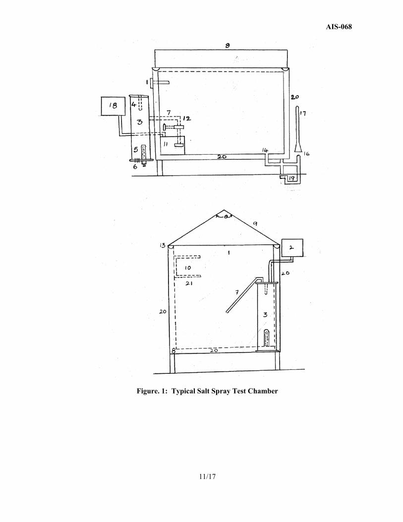
a fog chamber (shown in Fig.1 ), a salt solution conditioned compressed air, one or more atomizing nozzles, specimen supports, provision for heating the chamber, and necessary means of control. The size and detailed construction of the apparatus are optional, provided the conditions obtained meet the requirements of this practice.
4.2 Drops of solution, which accumulate on the ceiling or cover
of the chamber shall not be permitted to fall on the specimens being exposed.
4.3 Drops of the solution, which fall from the specimens, shall not
be returned to the solution reservoir for re-spraying. 4.4 Material of construction shall be such that it will not affect
the corrosiveness of the fog. 4.5 All water used for this practice shall conform to Type IV water
in specification D 1193 (except that for this practice limits for chlorides and sodium may be ignored). This does not apply to running tap water. All other water will be referred to as reagent grade.
5.0 Test Specimens 5.1. The type and number of test specimens to be used, as well as
the criteria for the evaluation of the test results, shall be defined in the specifications covering the material or product being exposed or shall be mutually agreed upon between the purchaser and the seller.
5/17
AIS-068
5.2. Preparation of Test Specimen 5.2.1. The specimen shall be suitably cleaned. The cleaning method shall
be optional depending on the nature of the surface and the contaminants. Care shall be taken that specimens are no re-contaminated after cleaning by excessive or careless handling.
5.2.2. Specimens for evaluation of paints and other organic coatings shall
be prepared in accordance with applicable specification(s) for the material(s) being exposed, or as agreed upon between the purchaser and supplier. Otherwise, the test specimens shall consist of steel meeting the requirements of practice D 609 and shall be cleaned and prepared for coating in accordance with the applicable procedure of practice D 609.
5.2.3. Specimens coated with paints or nonmetallic coatings shall not
be cleaned or handled excessively prior to test.
5.2.4. When ever it is desired to determine the development of corrosion from an abraded area in the paint or organic coating, a scratch or scribed line shall be made through the coating with a sharp instrument so as to expose to underlying metal before testing.
5.2.5 Scribing Tool should be a straight shank tungsten carbide tip, lathe
cutting tool or carbide tipped pencil-type is recommended. Any other type of scribing instrument such as a scalpel, razorblade, knife, or other sharp pointed tool is unacceptable.
5.2.6 Any straight edge of sufficient length and rigidity to guide the scribing
tool in straight line, and the tool should be hold at 450 to the surface. Position of the tool so that only the carbide tip is in contact with the surface. Pull the scribing tool to obtain a uniform V - cut through the coating that is being tested.
5.2.7 Inspect the tool frequently for dulling, chipping or wear and replace
or repair as needed. 5.2.8 Source of compressed air capable of delivering at least 0.283 m3/min
at 552 kPa.
5.2.9 Unless otherwise specified, the cut edges of plated, coated, or duplex materials and areas containing identification marks of in contact with then racks or supports shall be protected with a suitable coating stable under the conditions of the practice.
Note: Should it be desirable to cut test specimen from parts or from pre-plated, painted, otherwise coated steel sheet, the cut edges shall be protected by coating them with paint, wax, tape, or other effective media so that the development of a galvanic effect between such edges and the adjacent plated or otherwise coated metal surface, is prevented.
6/17
AIS-068
6.0 Position of Specimens during exposure 6.1 The position of the specimens in the salt spray chamber during the test
shall be such that the following conditions are met,
6.1.1. Unless otherwise specified, the specimens shall be supported between 15° to 30° from the vertical and preferably parallel to the principal direction of flow of fog through the chamber, based upon the dominant surface being tested.
6.1.2. The specimen shall not contact each other or any metallic material
or any material capable of acting as a wick. 6.1.3. Each specimen shall be so placed as to permit free settling of fog on
all specimens. 6.1.4. Salt solution from one specimen shall not drip on any other specimen.
Note: Suitable materials for the construction or coating of racks and supports are glass, rubber, plastic, or suitably coated wood. Bare metal shall not be used. Specimens shall preferably be supported from the bottom or the side. Slotted wooden strips are suitable for the support of flat panels. Suspension from glass hooks or waxed string may be used as long as the specified position of the specimens is obtained, if necessary be means of secondary support at the bottom of the specimens.
7.0 Salt Solution 7.1. The salt solution shall be prepared by dissolving 5 ± 1 parts by mass
of sodium chloride in 95 parts of water conforming to Type IV water in specification D 1193 (except that for this practice limits for chlorides and sodium may be ignored). The salt used shall be sodium chloride substantially free of nickel and copper and containing on the dry basis not more than 0.1% of sodium iodide and not more than 0.3% of the total impurities. Some salts contain additives that may act as corrosion inhibitors; careful attention should be given to the chemical content of the salt.
7.2. The PH of the salt solution shall be such that when atomized at 35°C
the collected solution will be in the PH range from 6.5 to 7.2. Before the solution is atomized it shall be free of suspended solids. The PH measurement shall be made at 25°C using a suitable glass PH sensing electrode, reference electrode and the PH meter system.
Note 1: The temperature affects the PH of a salt solution prepared from
water saturated with carbon dioxide at room temperature, and PH adjustments may be made by following three methods,
7/17
AIS-068
1. When the PH of the salt solution is adjusted at room temperature, and atomized at 35°C, the PH of the collected solution will be higher than the original solution due to loss of carbon dioxide at the higher temperature When the PH of the salt solution is adjusted at room temperature, it is therefore necessary to adjust it below 6.5 so the collected solution after atomizing at 35°C will meet the PH limits of 6.5 to 7.2. Take 50 ml sample of salt solution as prepared at room temperature, boil gently for 30s, cool, and determine the PH. When the PH of the atomized and collected solution at 35°C will come with in this range.
2. Heating the salt solution to boiling and cooling to 35°C
and maintaining it at 35°C for approximately 48 hr before adjusting the PH produces a solution the PH of which does not materially change when atomized at 35° C.
3. Heating the salt solution from which the salt solution is prepared
to 350C or above, to expel carbon dioxide, and adjusting the PH of the salt solution with in the limit of 6.5 to 7.2 produces PH of which does not materially change when atomized at 35°C.
Note 2: The freshly prepared salt solution may be filtered or decanted before it is placed in the reservoir, or the end of the tube leading from the solution to the atomizer may be covered with a double layer of cheesecloth to prevent plugging of the nozzle. Note 3: The PH can be adjusted by additions of dilute ACS re-agent grade hydraulic acid or sodium hydroxide solutions.
8.0 Air Supply 8.1 The compressed air supply to the nozzle or nozzles for atomizing
the salt solution shall be free of oil and dirt and maintained between 69 to 172 kPa/m2.
Note: The air supply may be freed from oil and dirt by passing it through a water scrubber or at least 610 mm of suitable cleaning material such as sheep’s wool, excelsior, slag wool, or activated alumina. Commercial cartridge, which includes an expiration indicator, may also be used.
9.0 Conditions of the Salt Spray Chamber 9.1. Temperature: The exposure zone of the salt spray chamber shall
be maintained at 35 + 1.1 - 1.7°C. The temperature within the exposure zone of the closed cabinet shall be recorded at least twice a day at least 7 hour apart.
Note: A suitable method to record the temperature is by a continuous
recording device or by a thermometer, which can be read from outside the closed cabinet. The record temperature must be obtained with the salt spray chamber closed to avoid a false low reading because of wet-bulb effect when the chamber is open.
8/17
AIS-068
9.2 Atomization and Quantity of Fog: At least two clean fog collectors shall be so placed within the exposure zone that no drops of solution from the test specimens or any other source shall be collected. The collectors shall be placed in the proximity of the test specimens, one nearest to any nozzle and other farthest from all nozzles. The fog shall be such that for each 80 cm2 of horizontal collecting area there will be collected in each collector from 1.0 to 2.0 ml of solution per hour based on average run of at least 16 hours. The sodium chloride concentration of the collected solution shall be 5 ± 1 mass percentage. The PH of the collected solution shall be 6.5 to 7.2.
Note 1: Suitable collecting devices are glass or plastic funnels with the
stems inserted through stoppers into graduated cylinders, or crystallizing dishes. Funnels and dishes with a diameter of 10 mm have an area of about 80 cm2.
Note 2 : A solution having specific gravity of 1.0255 to 1.0400
at 25°C will meet the concentration requirement. 9.3. The nozzle or nozzles shall be so directed or baffled that none
of the spray can impinge directly on the test specimens.
9.4. Continuity Exposure: Unless otherwise specified in the specifications covering the material or product being tested, the test shall be continuous for the duration of the entire test period. Continuous operation implies that the chamber be closed and the spray operating continuously except for the short daily interruptions necessary to inspect, rearrange, or remove test specimens, to check and replenish the solution in the reservoir, and to make necessary recording as described 5.3.9.1.
10.0 Period Of Exposure: The period of test duration is 7 days. 11.0 Cleaning of the Specimens: Unless otherwise specified in the
specifications covering the material or product being tested, specimen shall be treated as stated in
11.1 The specimens shall be carefully removed and the specimens shall
be gently washed or dipped in clean running water not warmer than 38° C to remove salt deposits from their surface, and then immediately dried.
12.0 Determination of Mass: Immediately after drying, determine the mass
loss by reweighing and subtracting specimen mass after exposure from its original mass.
12.1 Average mass loss should not be more than 2.5996 g.
9/17
AIS-068
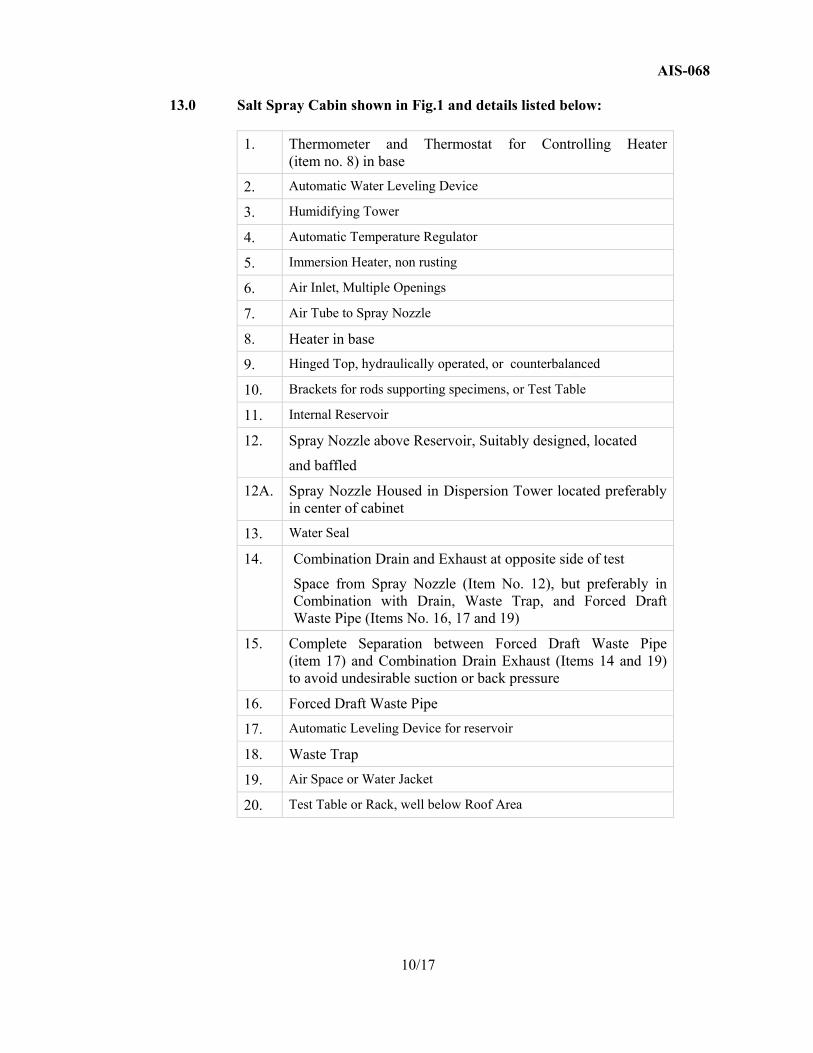
13.0 Salt Spray Cabin shown in Fig.1 and details listed below:
1. Thermometer and Thermostat for Controlling Heater (item no. 8) in base
2. Automatic Water Leveling Device
3. Humidifying Tower
4. Automatic Temperature Regulator
5. Immersion Heater, non rusting
6. Air Inlet, Multiple Openings
7. Air Tube to Spray Nozzle
8. Heater in base
9. Hinged Top, hydraulically operated, or counterbalanced
10. Brackets for rods supporting specimens, or Test Table
11. Internal Reservoir
12. Spray Nozzle above Reservoir, Suitably designed, located
and baffled
12A. Spray Nozzle Housed in Dispersion Tower located preferably in center of cabinet
13. Water Seal
14. Combination Drain and Exhaust at opposite side of test
Space from Spray Nozzle (Item No. 12), but preferably in Combination with Drain, Waste Trap, and Forced Draft Waste Pipe (Items No. 16, 17 and 19)
15. Complete Separation between Forced Draft Waste Pipe (item 17) and Combination Drain Exhaust (Items 14 and 19) to avoid undesirable suction or back pressure
16. Forced Draft Waste Pipe
17. Automatic Leveling Device for reservoir
18. Waste Trap
19. Air Space or Water Jacket
20. Test Table or Rack, well below Roof Area
10/17
AIS-068
Figure. 1: Typical Salt Spray Test Chamber
11/17
AIS-068 ANNEXURE : II
( See 5.4.6)
OZONE RESISTANCE TEST
1.0 Ozone Resistance
While in service, rubbers must resist the deterioration that ozone cracking produces. This test method covers the estimation of the resistance of vulcanized rubber to cracking when exposed to an atmosphere containing Ozone. The rubber specimens are kept under a surface tensile strain, and the ozone content or partial pressure in the test chamber is maintained at a fixed value. This test does not purport to address all of the safety concerns, if any associated with its use. It is the responsibility of the user of this standard to establish appropriate safety and health practices and determine the applicability of regulatory limitations prior to use.
2.0 Ozone Test Apparatus
2.1 Test Chamber
Requirement of an acceptable ozone test chamber is sufficient air-ozone throughout rate, sufficient internal circulation, and sufficient internal volume. A secondary requirement is that of controlling the temperature within acceptable limits. An acceptable ozone test chamber can be custom made in a particular laboratory or one of the commercial manufactured chambers, which are available, may be used. The ozone test chambers shall confirm to the following requirements.
2.2 The test chamber shall be constructed of a material with minimal
reaction to ozone. 2.3 The volume of chamber shall be at least 0.11 to .14 m3
2.4 A means for generating and controlling an air-ozone stream shall be provided. The generating source shall be located outside of the chamber. The source of air can be either drawn directly from a laboratory or from a compressed air supply. In either case adequate filtration of foreign matter from the stream must be provided. The air-ozone stream shall be introduced into the chamber in such a manner that stratification of ozone is prevented.
2.5 Irradiation of an air stream with a mercury vapor lamp is the most common source of the necessary ozonized air stream. The rate of ozone generation in this system can be easily controlled by adjusting the power input to the lamp. This adjustment may be manually or preferably, automatically controlled.
2.6 The air-ozone replacement rate of throughput rate must be of a magnitude such that no appreciable reduction of test specimens. This minimum replacement rate will vary with the ozone level, temperature, number of test specimens introduced, and their reaction with ozone. For many chambers operating under normal conditions (at an ozone partial pressure of approximately 50mPa), an air-ozone, replacement rate of a three-fourth change per minute is an acceptable and adequate value. For through and accurate work, especially under unusual conditions, the minimum or safe replacement rate should be determined.
12/17
AIS-068
2.7 A means of providing adequate internal circulation shall be provided.
The air-ozone velocity in the chamber shall be at least 0.6 m/s. Where it is doubtful that such velocities exit, the installation of an ordinary 1700 r/min electric motor and a fan blade of approximately 150 mm diameter and 20° to 30° pitch will produce such air velocities. The motor it self shall not be in the chamber. An extension shaft shall be used with an appropriate seal.
2.8 A means of controlling the temperature of the chamber shall
be provided. The temperature regulation should be capable of maintaining the test temperature within ± 1°C.
2.9 Ozone testing at optional sub-ambient test temperature requires the use
of refrigerated test chambers meeting the other requirements of this test method.
2.10 Chambers must be equipped such that the operator is never exposed
to harmful concentrations of ozone. This is done most commonly by exhausting the ozone from the test chamber before opening; however, other venting and protective measure may be used.
Note: Hazardous Warning: Ozone is a hazardous substance.
Consult and follow all applicable laws, rules, and regulations regarding exposure to ozone.
3.0 Sampling of Test Compounds or Products: A sampling process
should be used to ensure that he tests on specimens from either compounded or cured rubber sheets or specimens prepared from products are representative of the lot or other units to be compared.
4.0 Test Specimens: The following types of standard specimens are using
for testing.
4.1. Specimen A: A rectangular strip, 25 X 150 mm having a thickness between1.9 to 2.5 mm. This specimen is tested at 20% elongation unless otherwise specified.
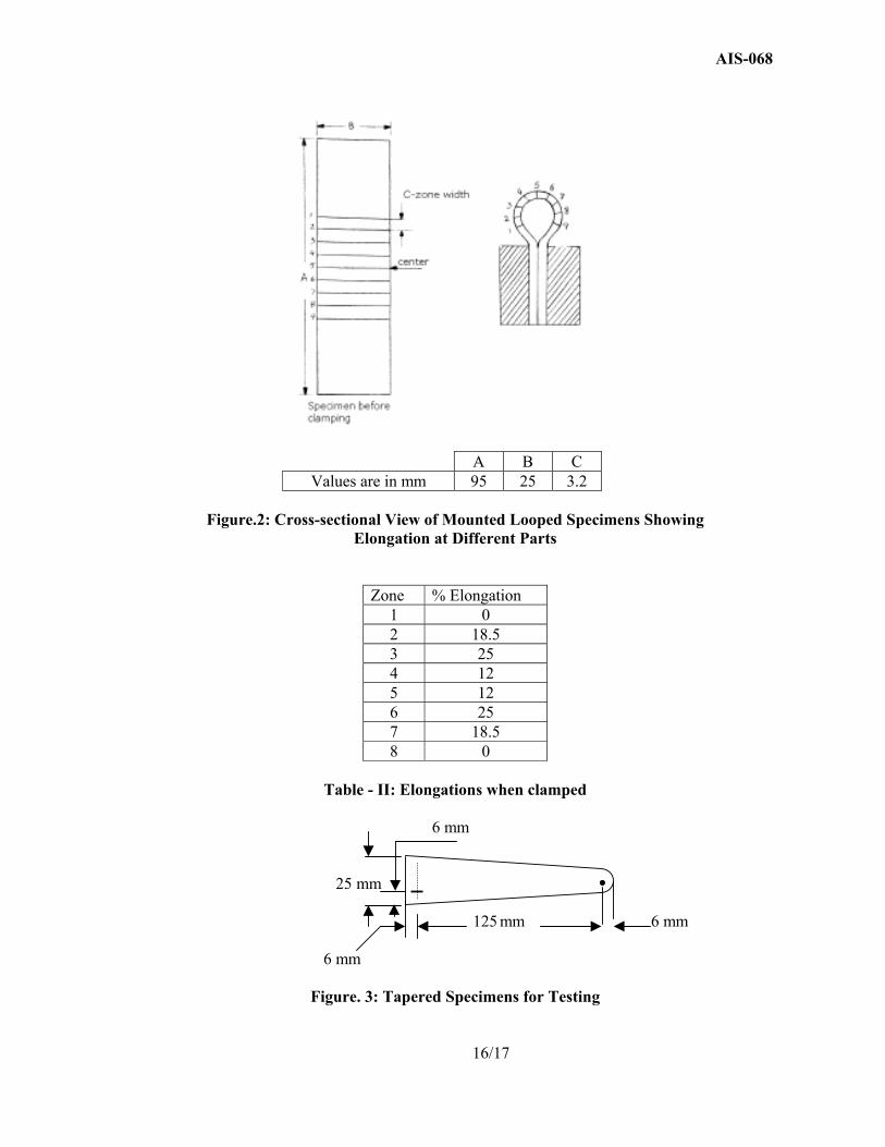
4.2. Specimen B: A rectangular strip 25 X 95 mm having a thickness between 1.9 to 2.5 mm. This specimen is tested in the form of a bent loop shown in Fig.1.
4.3. Specimen C: A Tapered strip shown in Fig. 2, having a thickness between 1.9 and 2.5 mm. This specimen tested in extension at 10, 15, or 20% elongation as specified. The actual elongation increase from the wide to the narrow end of the specimen.
5.0 Unless otherwise specified, the specimen shall be prepared with the grain in the length direction and duplicate specimens shall be tested. The type of specimen to be used shall be prescribed in specifications.
13/17
AIS-068
6.0 Test Method 6.1 Adjust ozone chamber to conditions for exposure. 6.2 Standard ozone pressures shall be 25 mPa, 50 mPa, 100 mPa
and 200 mPa with a ± 10% tolerance on each. Other partial pressure may, of course, be selected according to the particular goals of the test program, and they shall be referred to as optional partial pressure. The ozone concentration or partial pressure shall be measured once a day for routine work and more often for special test conditions. This measurement shall be made with the ozone chamber loaded with specimen. If specimens are loaded into a chamber that has been exhausted of ozone, the ozone concentration should reach ±10% of the selected ozone concentration within 15 min after the start of exposure.
6.3 Since new specimen tend absorb ozone rapidly, a drop in ozone
concentration may be noted in chambers that are not exhausted when they are first loaded. Generation and control of ozone to the chamber also shall recover to ±10% of the selected partial pressure within 15 min. these criteria may limit the number of new samples loaded at one time for a given test chamber.
6.4 The standard test temperature shall be 40°C. Any other temperature
may be chosen for the test and the associated conditioning. For certain types of protective films such as petroleum waxes, sub-ambient temperature testing may be of significant importance.
6.5 Mount and Condition the Specimens :
6.5.1 All rubber sheets for ozone testing shall be vulcanized between aluminum foil 0.05 mm in thickness or polyester film of similar thickness. These films will mildly adhere to most commercial rubbers. At the time specimens are cut for ozone testing, the foil or film can be easily removed providing a fresh surface.
6.5.2 The foil or film covered sheets shall be stored for a minimum of
3 hrs. at the agreed test temperature. 6.5.3 Strip off protective foil or film. Then extended specimens A and C
to the prescribed elongation and fasten them to holders inert to ozone (for example, metal or lacquered wood). Bend specimen B in the form of loop and fasten it in a holder inert to ozone as shown in Fig. 1. Initiate conditioning immediately after mounting specimens.
6.5.4 For normal testing, condition the mounted specimens for 24 hrs. in an ozone free atmosphere at the temperature, which they are to be exposed to ozone.
6.5.5 Minimum time of exposure to ambient conditions during transfer to the ozone test chamber, which shall have been preset to the agreed test temperature.
14/17
AIS-068
6.5.6 For better correlation with some types of exposure, condition the specimens for 1hr. in an ozone-free atmosphere at the temperature at which they are to be exposed.
6.5.7 Make observations for detecting the appearance of cracking with
sufficient frequency to be able to detect the first appearance of ozone cracking.
6.5.8 This frequency will depends on the resistance to ozone attack of
the rubbers being tested. The recommended observation magnification is 7X, except in the case of triangular specimen, where the magnification is 2X.
6.5.9 When comparisons are being made with a standard reference material,
exposure may be made for a fixed time. Evaluate the degree of cracking using an agreed upon scale.
15/17
AIS-068
A B C Values are in mm 95 25 3.2
Figure.2: Cross-sectional View of Mounted Looped Specimens Showing