1/7 AMENDMENT NO.2 To AIS-023 Automotive Vehicles - Seats, their Anchorages and Head Restraints for Passenger Vehicles of Categories M2, M3 and Goods Vehicles of Category N – Specifications 1.0 Page No. III, Introduction, after Sr. No. iv): Add Sr. No. v) as follows: “ECE R-107, (Revision 1/.. Suppl.2 of 02) Uniform provisions concerning the approval of category M 2 or M 3 vehicles with regard to their general construction” 2.0 Substitute “IS 15546:2005” for “AIS-016/2000” wherever it appears 3.0 Page No. 2/29, after clause 3.1.3: Add new clause 3.1.4 as follows: “3.1.4 Explanatory Note: Class I, Class II and Class III defined above in 3.1.1, 3.1.2 and 3.1.3 are equivalent to Type 1, Type II and Type III as per AIS 052 : Code of Practice for Bus Body Design and Approval. In case of any conflict in definition, related to category of buses, the definitions as given in AIS-052 will prevail.” 4.0 Page No. 3/29, after clause 3.19: Substitute following text for existing text in clause: “Seat spacing” means, the distance between the front of the seat back and the back of the seat back of the seat preceding it, measured horizontally at a height of 620 mm above the floor (Fig.6). Explanatory Note: All measurements shall be taken, with the seat cushion and squab uncompressed in the vertical plane passing through the centerline of the individual seating space.” 5.0 Page No. 6/29, after clause 4.2.2.2: Add new clause 4.2.2.3 as follows: For a seat behind a partition or other rigid structure other than a seat, a minimum clear space in front of each required passenger seating space (as defined in paragraph 4.3.1.10) shall be provided as shown in figure 7. A partition whose contour corresponds approximately to that of the inclined seat back may intrude into this space. In the case of seats alongside the driver's seat in vehicles with up to 22 passengers, intrusion of the
Transcript
1/7
AMENDMENT NO.2
To
AIS-023
Automotive Vehicles - Seats, their Anchorages and Head Restraints
for Passenger Vehicles of Categories M2, M3 and Goods Vehicles
of Category N – Specifications
1.0 Page No. III, Introduction, after Sr. No. iv):
Add Sr. No. v) as follows:
“ECE R-107, (Revision 1/.. Suppl.2 of 02) Uniform provisions concerning
the approval of category M2 or M3 vehicles with regard to their general
construction”
2.0 Substitute “IS 15546:2005” for “AIS-016/2000” wherever it appears
3.0 Page No. 2/29, after clause 3.1.3:
Add new clause 3.1.4 as follows:
“3.1.4 Explanatory Note: Class I, Class II and Class III defined above in
3.1.1, 3.1.2 and 3.1.3 are equivalent to Type 1, Type II and
Type III as per AIS 052 : Code of Practice for Bus Body Design
and Approval. In case of any conflict in definition, related to
category of buses, the definitions as given in AIS-052 will prevail.”
4.0 Page No. 3/29, after clause 3.19:
Substitute following text for existing text in clause:
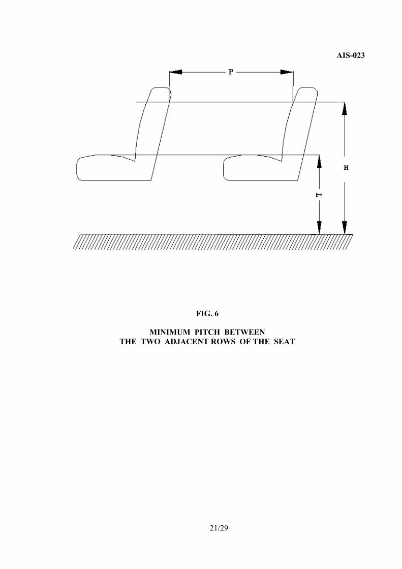
“Seat spacing” means, the distance between the front of the seat back and the
back of the seat back of the seat preceding it, measured horizontally at a height of
620 mm above the floor (Fig.6).
Explanatory Note: All measurements shall be taken, with the seat cushion and
squab uncompressed in the vertical plane passing through the centerline of the
individual seating space.”
5.0 Page No. 6/29, after clause 4.2.2.2:
Add new clause 4.2.2.3 as follows:
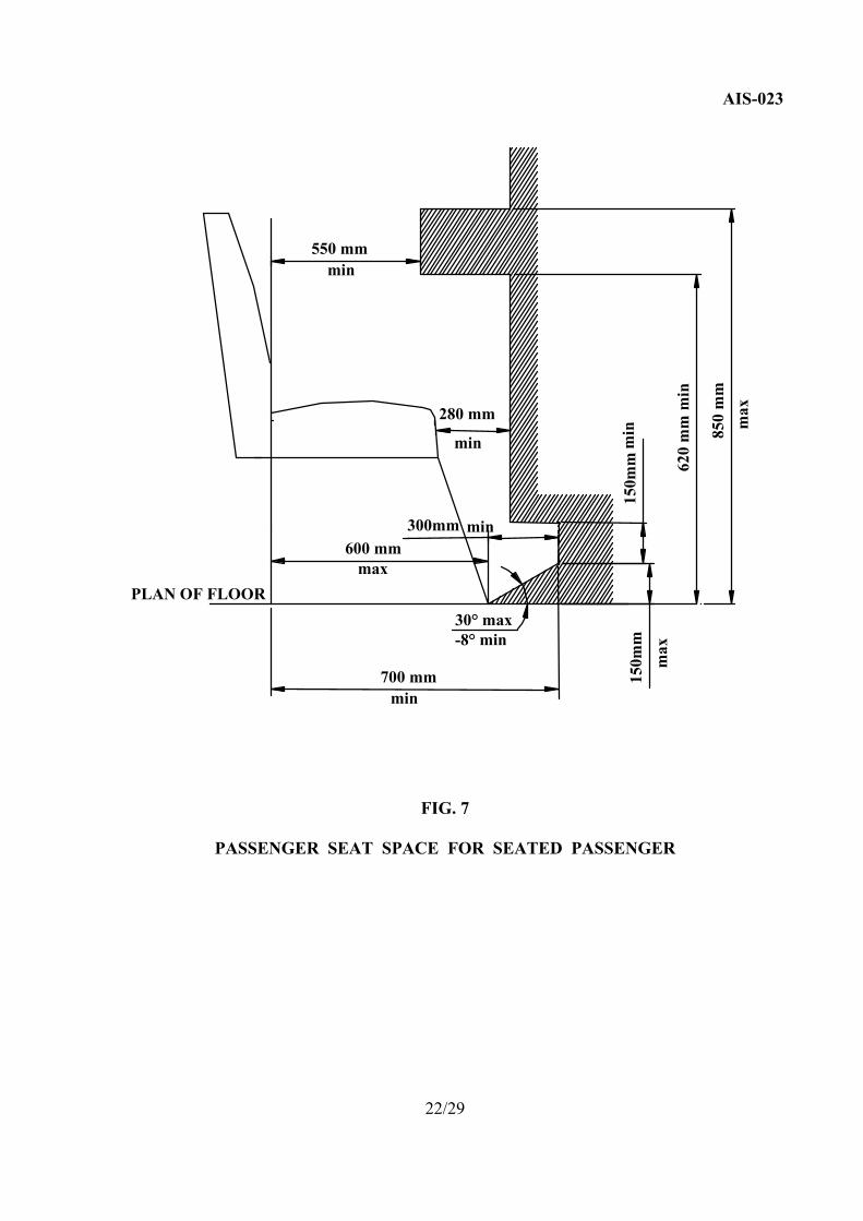
For a seat behind a partition or other rigid structure other than a seat, a minimum clear
space in front of each required passenger seating space (as defined in paragraph 4.3.1.10)
shall be provided as shown in figure 7. A partition whose contour corresponds
approximately to that of the inclined seat back may intrude into this space. In the case of
seats alongside the driver's seat in vehicles with up to 22 passengers, intrusion of the
2/7
dashboard, instrument panel, gear change control, windscreen, sun visor, seat belts and
seat belt anchorages shall be allowed.
6.0 Page No. 6/29, clause 4.3.1.1
Substitute following text for existing text
“ 4.3.1.1 Width of the seat cushion (2F) (Ref. Fig.3)
The minimum width of the seat cushion (2F) shall be:
M2 and Class I : 400 mm
Class II : 400 mm
Class III : 450 mm
Class III : 400mm for vehicles with width 2.35m or less
and/or vehicles with 3x2 seating layout”
7.0 Page No. 6/29, clause 4.3.1.2
Substitute following text for existing text of entire clause
“4.3.1.2 The minimum width of available space for each seating
position (2G) (Ref. Fig.3):
4.3.1.2.1 The minimum width of the available space for each seating position,
dimension G (Ref. Fig. 3A), measured from a vertical plane passing
through the centre of that seating position at height between 270 mm and
650 mm above the uncompressed seat cushion, shall be not less than:
Individual seats: 250 mm
Continuous rows of seats for two or more passengers : 225 mm.
In case of buses with 3 x 2 layout as defined in AIS 052 : “Code of
Practice for Bus Body Design and Approval”, the dimension G referred
above shall be 200 mm.
4.3.1.2.2 For vehicles 2.35 m in width or less, the width of the available space
for each seating position, measured from a vertical plane passing
through the centre of that seating position at heights between 270 mm
and 650 mm above the uncompressed seat cushion shall be 200 mm
(Ref. Fig. 3B). In case of compliance with this paragraph the
requirements of paragraph 4.3.1.2.1. shall not apply.
4.3.1.2.3 For vehicles having a capacity not exceeding 22 passengers, in the case
of seats adjacent to the wall of the vehicle, the available space does not
include, in its upper part, a triangular area 20 mm wide by 100 mm high
(Ref. Fig. 3C). In addition, the space needed for safety belts and their
anchorages and for the sun visor should be considered as exempted.
3/7
8.0 Page No. 6/29, after clause 4.3.1.3
Substitute following text for existing text
“4.3.1.3 The minimum backrest height (H) (Ref. Fig.3):
This is expressed as the vertical distance between the floor and
the top of the seat or headrest.
M2 and Class I : 800 mm
Class II : 1000 mm
Class III : 1100 mm”
9.0 Page No. 7/29, clause 4.3.1.4
Substitute following text for existing text
“4.3.1.4 The minimum depth of the uncompressed seat cushion (K),
measured along the longitudinal plane passing through the centre
of that seating position (Ref. Fig.4) :
M2 and Class I : 350 mm
Class II : 400 mm
Class III : 400 mm”
10.0 Page No. 7/29, clause 4.3.1.5
Substitute following text for existing text
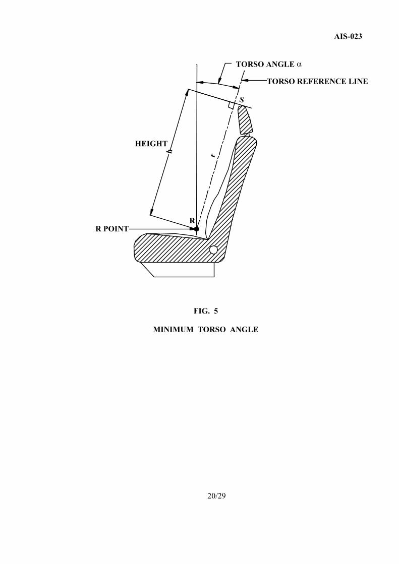
4.3.1.5 Minimum torso angle ( o)(Ref. Fig.5) :
M2 and Class I : 12o
Class II : 15o
Class III : 15o
11.0 Page No. 7/29, clause 4.3.1.7
Substitute following text for existing text
“Minimum seat spacing (P) (Ref. Fig.6):
The minimum seat spacing measured at a height of 620 mm (H in Fig. 6)
from the floor shall be :
M2 and Class I : 650 mm
Class II : 680 mm
Class III : 680 mm”
4/7
12.0 Page No. 7/29, after clause 4.3.1.10
Add new clauses 4.3.1.10.1
“4.3.1.10.1. In the case of a vehicle for up to 22 passengers, intrusion of
a wheel arch shall be permitted provided that one of the
following two conditions is fulfilled:
4.3.1.10.1.1. the intrusion does not extend beyond the median vertical plane of
the seating position (Ref. Fig. 7A), or
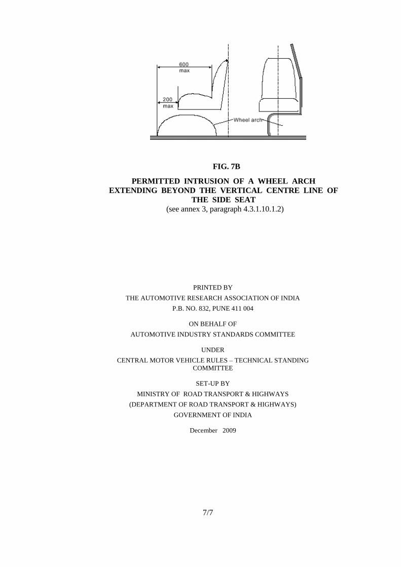
4.3.1.10.1.2. the nearest edge of the area 300 mm in depth available for the feet
of the seated passenger is advanced no more than 200 mm from the
edge of the uncompressed seat cushion and to not more than
600 mm in front of the squab of the seat, these measurements being
made in the median vertical plane of the seating position
(Ref. Fig. 7B). In the case of two seats facing each other this
provision shall apply to only one of the seats and the remaining
space for the feet of seated passengers must be at least 400 mm.”
13.0 Page No. 8/29, clause 4.3.1.11.2
Add following new sentence at the end of existing clause
- Intrusion of wheel arches, engine compartment and transmission tunnel etc.
14.0 Page No. 11/29, clause 4.5.1.5.2
Substitute following text for existing text
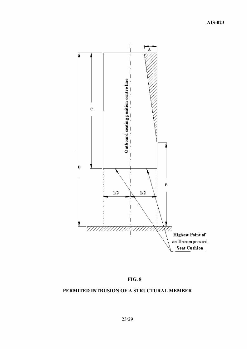
4.5.1.5.2 In the space ---------------peak is situated 650 mm (B in Fig.
8) from the floor and whose base is 100 mm (A in Fig. 8) in
width-----------transmission tunnel etc.
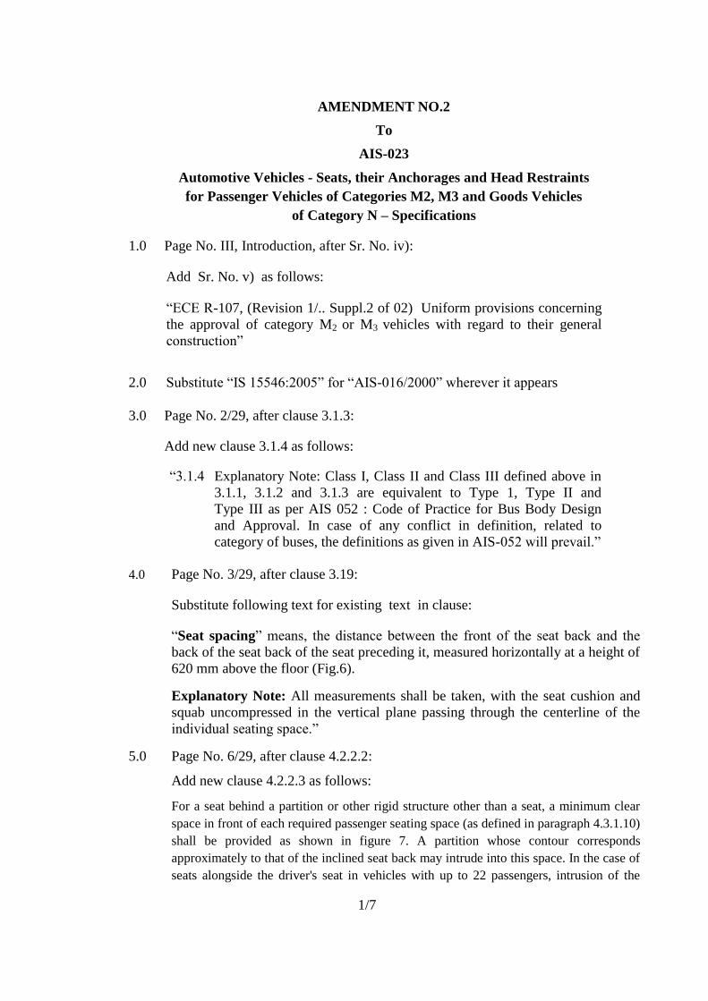
15.0 Page No. 18/29, Figure 3
Substitute following figure for existing figure
(delete reference „F” and „G‟)
FIG. 3
INDIVIDUAL AND CONTINUOUS PASSENGER SEAT
MINIMUM DIMENSIONS
5/7
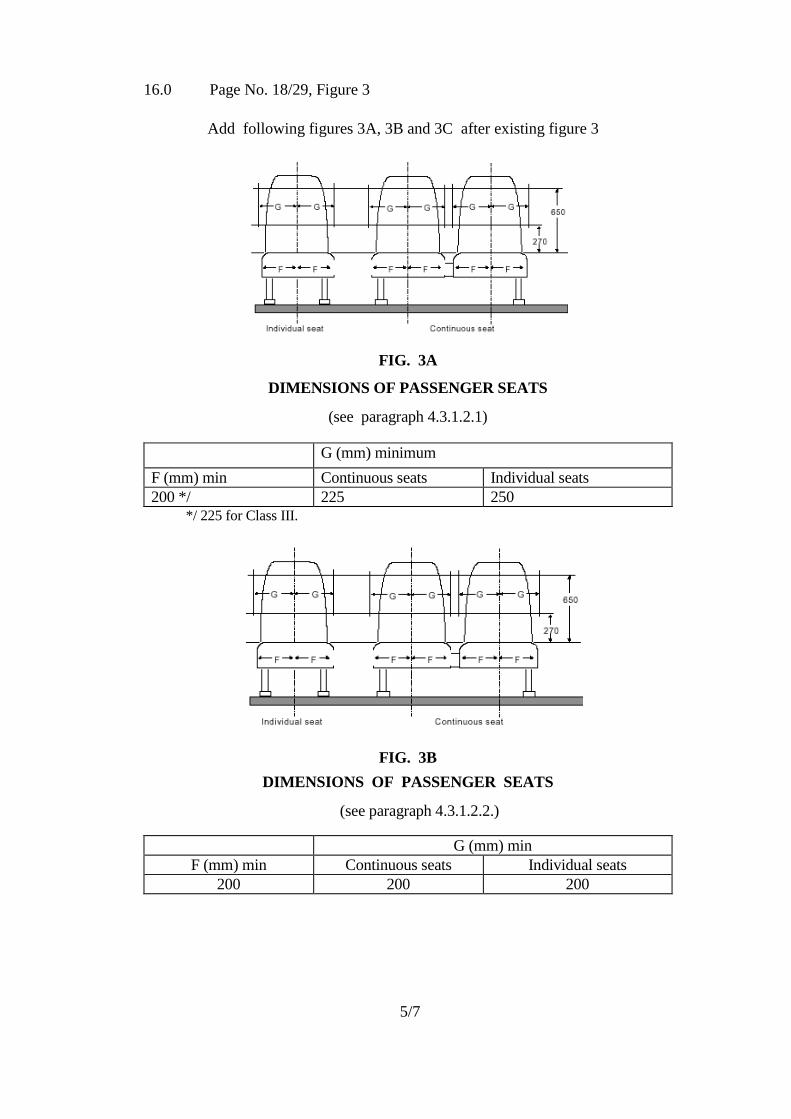
16.0 Page No. 18/29, Figure 3
Add following figures 3A, 3B and 3C after existing figure 3
FIG. 3A
DIMENSIONS OF PASSENGER SEATS
(see paragraph 4.3.1.2.1)
G (mm) minimum
F (mm) min Continuous seats Individual seats
200 */ 225 250
*/ 225 for Class III.
FIG. 3B
DIMENSIONS OF PASSENGER SEATS
(see paragraph 4.3.1.2.2.)
G (mm) min
F (mm) min Continuous seats Individual seats
200 200 200
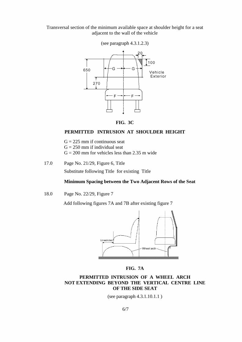
6/7
Transversal section of the minimum available space at shoulder height for a seat
adjacent to the wall of the vehicle
(see paragraph 4.3.1.2.3)
FIG. 3C
PERMITTED INTRUSION AT SHOULDER HEIGHT
G = 225 mm if continuous seat
G = 250 mm if individual seat
G = 200 mm for vehicles less than 2.35 m wide
17.0 Page No. 21/29, Figure 6, Title
Substitute following Title for existing Title
Minimum Spacing between the Two Adjacent Rows of the Seat
18.0 Page No. 22/29, Figure 7
Add following figures 7A and 7B after existing figure 7
FIG. 7A
PERMITTED INTRUSION OF A WHEEL ARCH
NOT EXTENDING BEYOND THE VERTICAL CENTRE LINE
OF THE SIDE SEAT
(see paragraph 4.3.1.10.1.1 )
7/7
FIG. 7B
PERMITTED INTRUSION OF A WHEEL ARCH
EXTENDING BEYOND THE VERTICAL CENTRE LINE OF
THE SIDE SEAT
(see annex 3, paragraph 4.3.1.10.1.2)
PRINTED BY
THE AUTOMOTIVE RESEARCH ASSOCIATION OF INDIA
P.B. NO. 832, PUNE 411 004
ON BEHALF OF
AUTOMOTIVE INDUSTRY STANDARDS COMMITTEE
UNDER
CENTRAL MOTOR VEHICLE RULES – TECHNICAL STANDING
COMMITTEE
SET-UP BY
MINISTRY OF ROAD TRANSPORT & HIGHWAYS
(DEPARTMENT OF ROAD TRANSPORT & HIGHWAYS)
GOVERNMENT OF INDIA
December 2009
AMENDMENT NO. 1
TO
AIS-023
Automotive Vehicles - Seats, their Anchorages and Head Restraints for Passenger Vehicles of Categories M2, M3 and
Goods Vehicles of Category N - Specifications
1. Page No. 6/29, clause No. 4.3.1.2: Add following text at the end:
“ 400 mm in the case of 3 x 2 layout buses as referred in AIS-052.”
PRINTED BY
THE AUTOMOTIVE RESEARCH ASSOCIATION OF INDIA P.B. NO. 832, PUNE 411 004
ON BEHALF OF
AUTOMOTIVE INDUSTRY STANDARDS COMMITTEE
UNDER CENTRAL MOTOR VEHICLE RULES – TECHNICAL STANDING COMMITTEE
SET-UP BY
MINISTRY OF SHIPPING, ROAD TRANSPORT & HIGHWAYS (DEPARTMENT OF ROAD TRANSPORT & HIGHWAYS)
GOVERNMENT OF INDIA
July 2008
1/1
AIS-023
AUTOMOTIVE INDUSTRY STANDARD
Automotive Vehicles - Seats, their Anchorages and
Head Restraints for Passenger Vehicles of Categories M2, M3 and Goods Vehicles of
Category N - Specifications
PRINTED BY THE AUTOMOTIVE RESEARCH ASSOCIATION OF INDIA
P.B. NO. 832, PUNE 412 004
ON BEHALF OF AUTOMOTIVE INDUSTRY STANDARDS COMMITTEE
UNDER
CENTRAL MOTOR VEHICLE RULES - TECHNICAL STANDING COMMITTEE
SET-UP BY MINISTRY OF SHIPPING, ROAD TRANSPORT & HIGHWAYS
( DEPARTMENT OF ROAD TRANSPORT & HIGHWAYS ) GOVERNMENT OF INDIA
September 2005
I
AIS-023
Status chart of the Standard to be used by the purchaser for
updating the record Sr. No.
Corr-igenda.
Amend- ment
Revision Date Remark Misc.
General Remarks :
II
AIS-023
INTRODUCTION
The Government of India felt the need for a permanent agency to expedite the publication of standards and development of test facilities in parallel when the work on the preparation of the standards is going on, as the development of improved safety critical parts can be undertaken only after the publication of the standard and commissioning of test facilities. To this end, the Ministry of Surface Transport (MOST) has constituted a permanent Automotive Industry Standards Committee (AISC) vide order No.RT-11028/11/97-MVL dated September 15, 1997. The standards prepared by AISC will be approved by the permanent CMVR Technical Standing Committee (CTSC). After approval, the Automotive Research Association of India, (ARAI), Pune, being the Secretariat of the AIS Committee, has published this standard. For better dissemination of this information ARAI may publish this document on their Web site. Seats, seat belts, seat belt anchorages etc., are safety critical items for occupant in case of sudden accelerations/decelerations and accidents. Further, seats and their design, mounting etc. constitute substantially to the ride comfort of the vehicle users. The Indian Standard/AIS have been in place for M1 category of vehicles. The need was felt for such item for covering M2, M3, N1, N2 and N3 category vehicles. Already this has been identified as priority item in Safety Road Map. Therefore AIS-023 has been formulated to cover these needs. This standard covers requirements for driver and passenger seats with regard to their strength and dimensions. While formulating the above standard, considerable assistance has been taken from: i) ECE-R-80 ( Amd. 3 – Supp. 2 to the 01 series of amendments)
Uniform provisions concerning the approval of seats of large passenger vehicles and of these vehicles with regard to the strength of seats and their anchorages.
ii) EEC Directive 74/408/EEC as amended by 96/37/EC on Motor vehicles with regard to the seats, their anchorages and head restraints.
iii) ECE-R-36 (Revision 2 – Supp.6 to the 03 series of amendments) Uniform provisions concerning the approval of large passenger vehicles with
regard to their general construction.’ iv) ECE-R-52 (Revision 1, Amd.1- Supp.1 to the 01 series of amendments)
Uniform provisions concerning the construction of small capacity public service vehicles.
The Automotive Industry Standards Committee responsible for preparation of this standard is given in Annexure- II
III
AIS-023
Automotive Vehicles - Seats, their Anchorages and Head Restraints for Passenger Vehicles of Categories M2, M3 and Goods Vehicles of
Category N - Specifications 1. SCOPE 1.1 This standard specifies the requirements of the dimensions, space and strength
of the seats (both driver and passengers) and their anchorages, whether or not fitted with head restraints and the characteristics of head restraints of passenger carrying vehicles of categories M2, M3 and goods vehicles of category N in respect to the seats intended to be installed facing forward.
1.2 It does not apply to folding, side-facing or rearward-facing seats, sleeper seats
or to any head restraints fitted to these seats. 2. REFERENCES 2.1 The following Indian/other national Standards are necessary adjunct to this
standard : 2.1.2 IS:13749-1993 : Automotive vehicle – Determination of H-Point – Method of
Test (under revision). 2.1.3 AIS-053 : Automotive Vehicles -Types - Terminology 2.1.4 ISO:6487-1987 : Road Vehicles - Measurement Techniques in Impact Test -
Instrumentation. 2.1.5 AIS-016/2000 : Automotive Vehicles - Seats, Their Anchorages and Head
Restraints for Category M1 - Specifications. 2.1.6 IS:15061-2002 : Automotive Vehicles - Flammability Requirements 3. DEFINITIONS For the purposes of this standard 3.1 “Vehicle” means a vehicle of Group A or Group B as described below :
Group A – means vehicles of categories N2, N3 and M3. It also includes vehicles of M2 category with GVW exceeding 3.5 tonnes. The vehicles of category M3 are further classified into :
Class I : city buses / ordinary
Class II : interurban buses or coaches / semi luxury Class III: touring coaches / luxury
1/29
AIS-023 Group B – means vehicles of categories N1 and M2 with GVW up to 3.5 tones
The categories M2, M3, N1, N2 and N3 are as defined in AIS-053 : Automotive Vehicles – Types and Terminology.
3.1.1 “Vehicle of Class I” means a city bus; a vehicle of this Class has seats and
space for standing passengers; 3.1.2 “Vehicle of Class II” means an inter-urban bus or coach; a vehicle of this
Class may have provision for standing passengers, but only on the gangway; 3.1.3 “Vehicle of Class III” means a touring coach; a vehicle of this Class has no
provision for standing passengers; 3.2 “Seat” means a structure which may or may not be integral with the vehicle
structure complete with trim, intended to seat one adult person. The term covers both an individual seat or part of a bench seat intended to seat one person;
3.3 “Individual seat” means a seat designed and constructed for the
accommodation of one seated passenger; 3.4 “Bench seat” means a structure complete with trim, intended to seat more
than one adult person; 3.5 “Group of seats” means either a bench type seat or seats which are separable
but side-by-side (i.e. fixed so that the front seat anchorage of one of these seats is in line with front or rear anchorage of the other or between the anchorage of the other seat) and seat one or more adults.
3.6 “Driver seat” means the right out board front seat intended for the seating of
the driver. 3.7 “Front passenger seat” means any seat where the H Point measured in the
foremost position(s) of the seating position is in or in-front-of the vertical transverse plane through the driver’s R Point. This is generally an individual seat, but can be a bench seat.
3.8 “Passenger seat” means the seats intended for seating passengers.
3.9 “Seat cushion” means the part of the seat which is arranged almost
horizontally and designed to support a seated passenger; 3.10 “Seat-back” means the part of the seat that is almost vertical, designed to
support the passenger’s back, shoulders and, possibly his head; 3.11 “Adjustment system” means the device by which the seat or its parts can be
adjusted to a position suited to the seated occupant;
2/29
AIS-023 3.12 “Displacement system” means a device enabling the seat or one of its parts
to be displaced laterally or longitudinally without a fixed intermediate position of the seat or one of its parts, to facilitate access by passengers;
3.13 “Locking system” means a device ensuring that the seat and its parts are
maintained in the position of use; 3.14 “Anchorage” means a part of the floor or of the body of a vehicle to which a
seat may be fixed; 3.15 “Attachment fittings” means bolts or other components used to attach the
seat to the vehicle; 3.16 “Reference plane” means the plane passing through the points of contact of
the heels of the manikin, used for the determination of the H point and the actual angle of torso for the seating position of motor vehicles according to the method specified in IS:13749:1993.
3.17 “Reference height” means the height of the top of the seat above the
reference plane; 3.18 “Floor” means that part of the bodywork whose upper surface supports
standing passengers, the feet of seated passengers and the driver, and the seat mountings;
3.19 “Seat pitch” means, the distance between the front seat squab and the back
of the seat squab of the seat preceding it, measured horizontally at a height of 620 mm above the floor (Fig.6).
3.20 “Transverse Plane” means a vertical plane perpendicular to the median
longitudinal plane of the vehicle (refer IS:13749:1993). 3.21 “Longitudinal Plane” means a plane parallel to the median longitudinal
plane of the vehicle (refer IS:13749:1993). 3.22 “Reference zone” means the space between two vertical longitudinal planes,
400 mm apart and symmetrical with respect to the H-point, and defined by rotation from vertical to horizontal of the head-form apparatus whose dimensions from the pivotal point of the hip to the top of the head is continuously adjustable between 736 mm and 840 mm.
3.23 “Head Restraint” means a device whose purpose is to limit the rearward displacement of an adult occupant’s head in relation to his torso in order to reduce the danger of injury to the cervical vertebrae in the event of an accident;
3.24 “Integrated Head Restraint” means a head restraint formed by the upper part of the seat back. Head restraints meeting the definitions of para 3.25 or 3.26 below but which can only be detached from the seat or the vehicle structure by the use of tools or by partial or complete removal of the seat covering meet the present definition;
3/29
AIS-023 3.25 “Detachable Head Restraint” means a head restraint consisting of
a component separable from the seat, designed for insertion and positive retention in the seat-back structure;
3.26 “Separate Head Restraint” means a head restraint consisting of
a component separate from the seat, designed for insertion and/or positive retention in the structure of the vehicle;
3.27 “R-point” or ‘Seating Reference Point’ means the manufacturer’s design
H-point which establishes the rearmost normal driving or riding position of each designated seating position as stipulated by the manufacturer and which accounts for all modes of adjustments (horizontal, vertical and tilt) that are available for the seat; has co-ordinates established with respect to the designed vehicle structure; simulates the position of the pivot centre of the human torso and thigh; and is the reference point employed to position a two-dimensional template (ref. IS:13749:1993).
3.28 “Torso Reference Line” means a straight line passing through the joint
between the leg and the pelvis and the theoretical joint between the neck and thorax of the manikin (ref. Fig.5 and IS:13749:1993).
3.29 “Seat type” means seats which do not differ essentially with respect to the
following characteristics likely to affect their strength and their aggressiveness:
3.29.1 Structure, shape, dimensions and materials of the load bearing parts; 3.29.2 Types and dimensions of the seat back adjustment and locking system; 3.29.3 Dimensions, structure and materials of the attachments and supports
(e.g. legs); 3.30 “Approval of a seat” means the approval of a seat type in relation to the
protection of the occupants of forward facing seats with regard to their strength and the design of seat backs.
3.31 “Vehicle type” means vehicles which do not differ essentially in respect of: 3.31.1 The constructional features relevant to this Standard; and 3.31.2 The type of type approved seat(s) fitted to the vehicle, if any. 3.32 “Approval of a vehicle” means the approval of a vehicle type with regard
to the strength of the seats, their anchorages and the characteristics of their head restraints, if fitted and with regard to the installation of seats:
4/29
AIS-023 4. REQUIREMENTS 4.1 The seat/vehicle manufacturer shall furnish the information about the seats,
its attachment fittings and adjustment, displacement and locking systems as well as parts of the structure of the vehicle used as anchorages and drawings of the above in the format given in Annexure-1. Note : Due to inherent variations in body and seat construction, upholstery, seat cushion manufacture etc. variations in dimensions upto ± 15 mm are possible.
4.2 The seat material in CNG or LPG fueled vehicles, shall comply flammability
requirements as per IS:15061-2002 4.2 Requirements applicable to Driver Seat and Front Passenger Seat(s) for
vehicles of Group A 4.2.1 Dimensional Requirements of Driver Seat The dimensions shall be as follows (Ref. Fig.1): 4.2.1.1 Minimum width of the cushion (A): 450 mm. 4.2.1.2 Minimum depth of the cushion (B), measured along the longitudinal plane
passing through the centre of that seating position : 445 mm. 4.2.1.3 Minimum seat back rest height (C):
For the driver seats without head restraints : 325 mm. This height shall be measured from the R point to the top of the seat back. For the driver seats if provided with head restraints adjustable for height, this value shall be 750 mm from the R point and obtained in a position between the highest and lowest positions of the head restraints to which adjustment is possible, measured parallel to the seat back.
4.2.1.4 Torso Angle (α o) : It shall be possible to adjust the reclination of seat back
to not less than 12 o to the rear measured from the vertical in steps not exceeding 3 o each.
4.2.1.5 The height adjustment of the seat may be provided as an optional feature. 4.2.1.6 Minimum longitudinal adjustment (∆L): 120 mm in steps not exceeding
15 mm each. 4.2.2 Dimensional Requirements for Front Passenger Seat 4.2.2.1 The front passenger seat can be a fixed seat i.e. need not be provided with
reclination, height and longitudinal adjustment.
5/29
AIS-023
4.2.2.2 The front passenger seat (individual or bench) shall meet the dimensional requirements of passenger seats as specified in para. 4.4.2.2.1, 4.4.2.2.2, 4.4.2.2.3, 4.2.1.3 and the vehicle controls such as gear shift lever, pedals, steering wheel, etc., and dash-board shall not intrude into the space specified in Fig.7. If the seat is adjustable, then these requirements shall be met for the specified range of adjustments.
4.2.3 Performance and Strength Requirements 4.2.3.1 Both driver and front passenger seats and their head restraints (if provided)
shall meet the requirements laid down in para. 5 “Tests” (except para. 5.9.3.4) of "AIS-016/2000-Automotive Vehicles - Seats, Their Anchorages and Head Restraints for Category M1- Specifications".
4.2.3.2 However, for the purposes of this standard, para. 5.3.1 of AIS-016/2000
shall be read as –
"A longitudinal horizontal deceleration corresponding to the deceleration pulse given in Fig. 2 of AIS-023 shall be applied to the relevant portion of the shell of the vehicle in the forward and rearward directions, one after the other, in accordance with requirements of para. 5.3.3 of AIS-016/2000".
4.3 Passenger Seats (other than front passenger seat) for Passenger Vehicles of Group A
4.3.1 Dimensional Requirements 4.3.1.1 Width of the seat cushion (2F) (Ref. Fig.3)
The minimum width of the seat cushion (2F) shall be:
Class I : 400 mm M2 and Class II : 400 mm Class III : 450 mm
4.3.1.2 The minimum width of available space for each seating position (2G) (Ref. Fig.3) :
The minimum width of the available space for each seating position (2G), measured from a vertical plane passing through the centre of that seating position between heights of 270 mm and 650 mm (B and C respectively in Fig. 3) above the uncompressed seat cushion, shall be :
500 mm in the case of individual seats, and 450 mm in the case of bench seats. 4.3.1.3 The minimum backrest height (H) (Ref. Fig.3):
This is expressed as the vertical distance between the floor and the top of the seat or headrest.
Class I : 800 mm M2 and Class II : 1000 mm Class III : 1100 mm
6/29
AIS-023
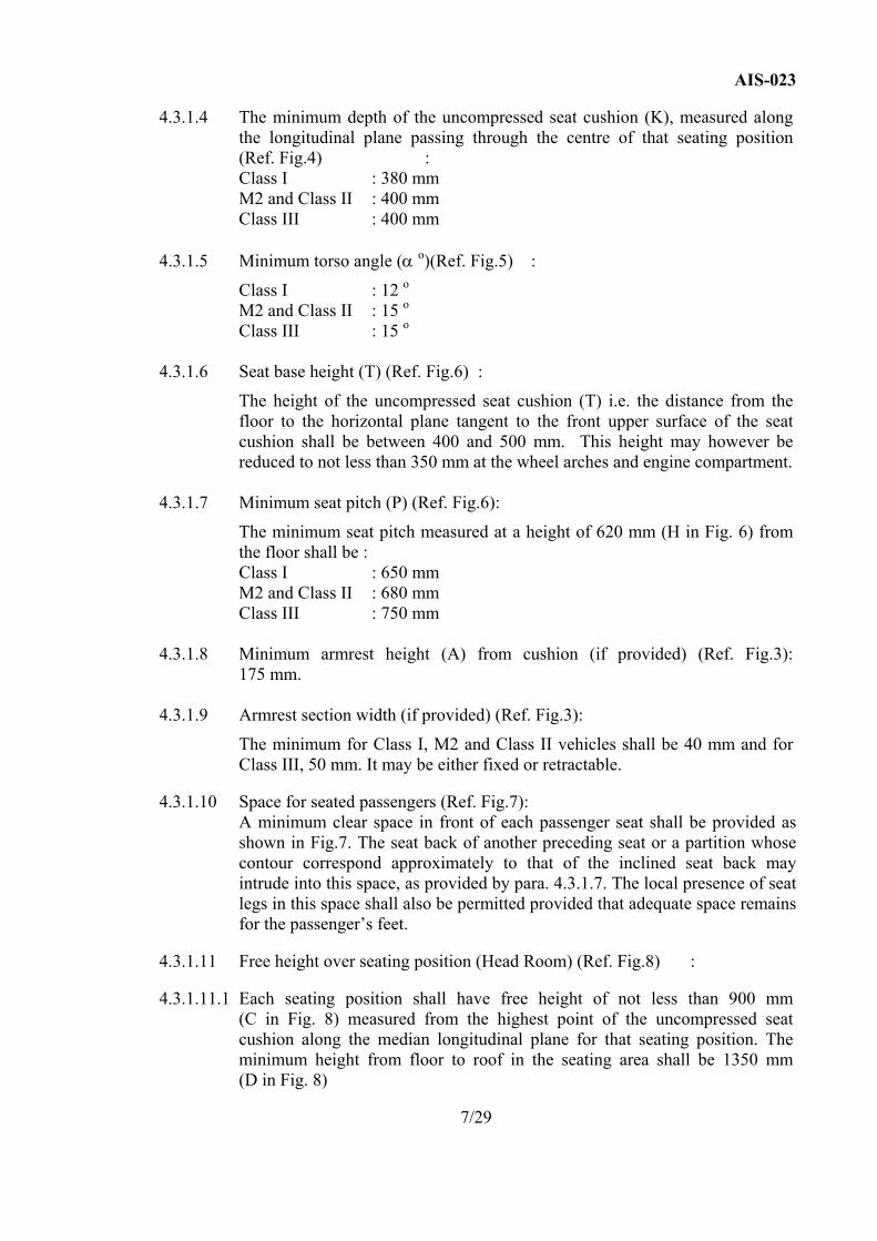
4.3.1.4 The minimum depth of the uncompressed seat cushion (K), measured along the longitudinal plane passing through the centre of that seating position (Ref. Fig.4) :
Class I : 380 mm M2 and Class II : 400 mm Class III : 400 mm 4.3.1.5 Minimum torso angle (α o)(Ref. Fig.5) :
Class I : 12 o M2 and Class II : 15 o Class III : 15 o 4.3.1.6 Seat base height (T) (Ref. Fig.6) :
The height of the uncompressed seat cushion (T) i.e. the distance from the floor to the horizontal plane tangent to the front upper surface of the seat cushion shall be between 400 and 500 mm. This height may however be reduced to not less than 350 mm at the wheel arches and engine compartment.
4.3.1.7 Minimum seat pitch (P) (Ref. Fig.6):
The minimum seat pitch measured at a height of 620 mm (H in Fig. 6) from the floor shall be :
Class I : 650 mm M2 and Class II : 680 mm Class III : 750 mm 4.3.1.8 Minimum armrest height (A) from cushion (if provided) (Ref. Fig.3):
175 mm. 4.3.1.9 Armrest section width (if provided) (Ref. Fig.3):
The minimum for Class I, M2 and Class II vehicles shall be 40 mm and for Class III, 50 mm. It may be either fixed or retractable.
4.3.1.10 Space for seated passengers (Ref. Fig.7): A minimum clear space in front of each passenger seat shall be provided as
shown in Fig.7. The seat back of another preceding seat or a partition whose contour correspond approximately to that of the inclined seat back may intrude into this space, as provided by para. 4.3.1.7. The local presence of seat legs in this space shall also be permitted provided that adequate space remains for the passenger’s feet.
4.3.1.11 Free height over seating position (Head Room) (Ref. Fig.8) : 4.3.1.11.1 Each seating position shall have free height of not less than 900 mm
(C in Fig. 8) measured from the highest point of the uncompressed seat cushion along the median longitudinal plane for that seating position. The minimum height from floor to roof in the seating area shall be 1350 mm (D in Fig. 8)
7/29
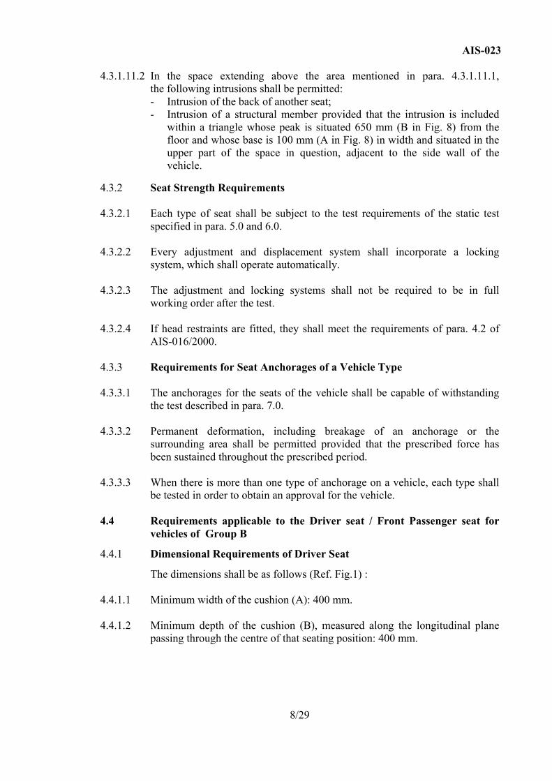
AIS-023 4.3.1.11.2 In the space extending above the area mentioned in para. 4.3.1.11.1,
the following intrusions shall be permitted: - Intrusion of the back of another seat;
- Intrusion of a structural member provided that the intrusion is included within a triangle whose peak is situated 650 mm (B in Fig. 8) from the floor and whose base is 100 mm (A in Fig. 8) in width and situated in the upper part of the space in question, adjacent to the side wall of the vehicle.
4.3.2 Seat Strength Requirements 4.3.2.1 Each type of seat shall be subject to the test requirements of the static test
specified in para. 5.0 and 6.0. 4.3.2.2 Every adjustment and displacement system shall incorporate a locking
system, which shall operate automatically. 4.3.2.3 The adjustment and locking systems shall not be required to be in full
working order after the test. 4.3.2.4 If head restraints are fitted, they shall meet the requirements of para. 4.2 of
AIS-016/2000. 4.3.3 Requirements for Seat Anchorages of a Vehicle Type 4.3.3.1 The anchorages for the seats of the vehicle shall be capable of withstanding
the test described in para. 7.0. 4.3.3.2 Permanent deformation, including breakage of an anchorage or the
surrounding area shall be permitted provided that the prescribed force has been sustained throughout the prescribed period.
4.3.3.3 When there is more than one type of anchorage on a vehicle, each type shall
be tested in order to obtain an approval for the vehicle.
4.4 Requirements applicable to the Driver seat / Front Passenger seat for vehicles of Group B
4.4.1 Dimensional Requirements of Driver Seat
The dimensions shall be as follows (Ref. Fig.1) : 4.4.1.1 Minimum width of the cushion (A): 400 mm. 4.4.1.2 Minimum depth of the cushion (B), measured along the longitudinal plane
passing through the centre of that seating position: 400 mm.
8/29
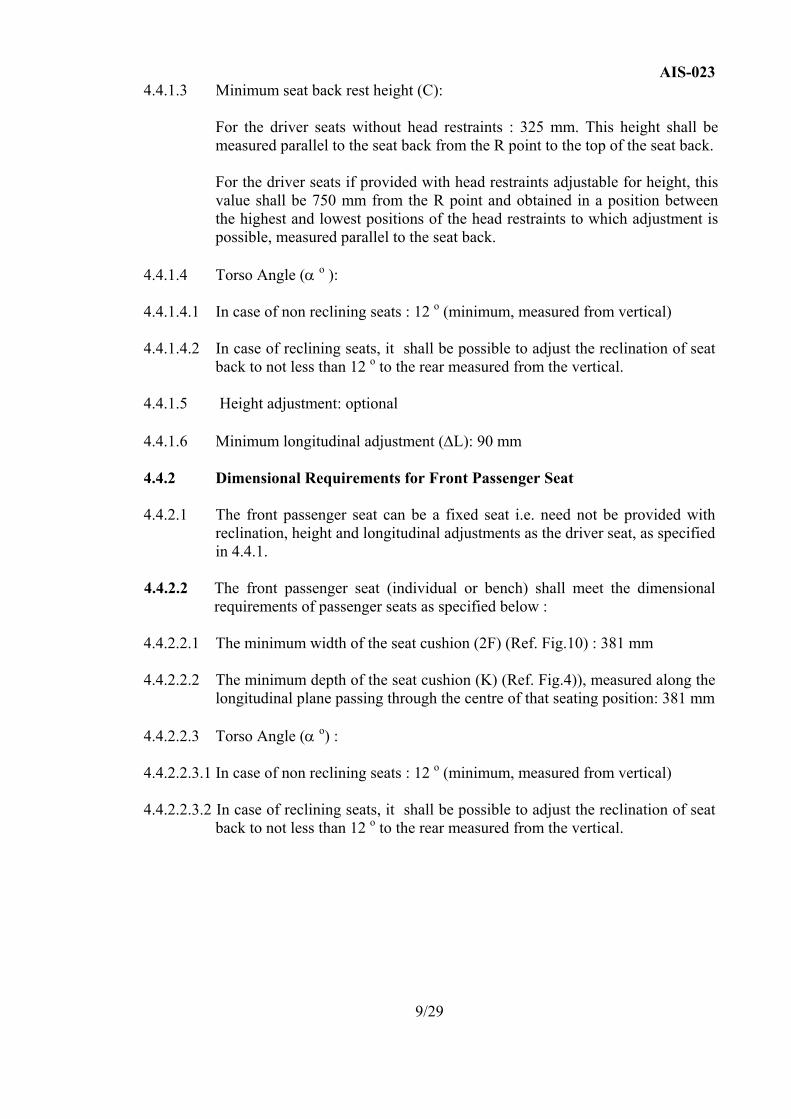
AIS-023 4.4.1.3 Minimum seat back rest height (C):
For the driver seats without head restraints : 325 mm. This height shall be measured parallel to the seat back from the R point to the top of the seat back. For the driver seats if provided with head restraints adjustable for height, this value shall be 750 mm from the R point and obtained in a position between the highest and lowest positions of the head restraints to which adjustment is possible, measured parallel to the seat back.
4.4.1.4 Torso Angle (α o ): 4.4.1.4.1 In case of non reclining seats : 12 o (minimum, measured from vertical) 4.4.1.4.2 In case of reclining seats, it shall be possible to adjust the reclination of seat
back to not less than 12 o to the rear measured from the vertical. 4.4.1.5 Height adjustment: optional 4.4.1.6 Minimum longitudinal adjustment (∆L): 90 mm
4.4.2 Dimensional Requirements for Front Passenger Seat 4.4.2.1 The front passenger seat can be a fixed seat i.e. need not be provided with
reclination, height and longitudinal adjustments as the driver seat, as specified in 4.4.1.
4.4.2.2 The front passenger seat (individual or bench) shall meet the dimensional
requirements of passenger seats as specified below : 4.4.2.2.1 The minimum width of the seat cushion (2F) (Ref. Fig.10) : 381 mm 4.4.2.2.2 The minimum depth of the seat cushion (K) (Ref. Fig.4)), measured along the
longitudinal plane passing through the centre of that seating position: 381 mm
4.4.2.2.3 Torso Angle (α o) : 4.4.2.2.3.1 In case of non reclining seats : 12 o (minimum, measured from vertical) 4.4.2.2.3.2 In case of reclining seats, it shall be possible to adjust the reclination of seat
back to not less than 12 o to the rear measured from the vertical.
9/29
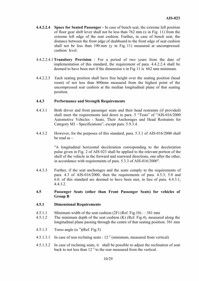
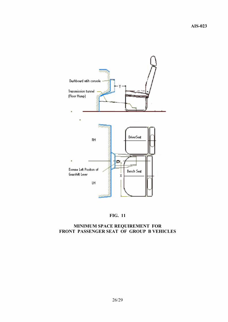
AIS-023 4.4.2.2.4 Space for Seated Passenger - In case of bench seat, the extreme left position
of floor gear shift lever shall not be less than 762 mm (x in Fig. 11) from the extreme left edge of the seat cushion. Further, in case of bench seat, the distance between the front edge of dashboard to the front edge of seat cushion shall not be less than 190 mm (y in Fig. 11) measured at uncompressed
cushion level. 4.4.2.2.4.1 Transitory Provision : For a period of two years from the date of
implementation of this standard, the requirement of para. 4.4.2.2.4 shall be deemed to have been met if the dimension x in Fig 11 is 662 mm minimum.
4.4.2.2.5 Each seating position shall have free height over the seating position (head
room) of not less than 800mm measured from the highest point of the uncompressed seat cushion at the median longitudinal plane of that seating position.
4.4.3 Performance and Strength Requirements 4.4.3.1 Both driver and front passenger seats and their head restraints (if provided)
shall meet the requirements laid down in para. 5 “Tests” of "AIS-016/2000 Automotive Vehicles - Seats, Their Anchorages and Head Restraints for Category M1 - Specifications”, except para. 5.9.3.4.
4.4.3.2 However, for the purposes of this standard, para. 5.3.1 of AIS-016/2000 shall
be read as –
"A longitudinal horizontal deceleration corresponding to the deceleration pulse given in Fig. 2 of AIS 023 shall be applied to the relevant portion of the shell of the vehicle in the forward and rearward directions, one after the other, in accordance with requirements of para. 5.3.3 of AIS-016/2000".
4.4.3.3 Further, if the seat anchorages and the seats comply to the requirements of
para. 4.3 of AIS-016/2000, then the requirements of para. 4.5.3, 5.0 and 6.0. of this standard are deemed to have been met, in lieu of para. 4.4.3.1, 4.4.3.2.
4.5 Passenger Seats (other than Front Passenger Seats) for vehicles of
Group B 4.5.1 Dimensional Requirements 4.5.1.1 Minimum width of the seat cushion (2F) (Ref. Fig.10) : : 381 mm 4.5.1.2 The minimum depth of the seat cushion (K) (Ref. Fig.4), measured along the
longitudinal plane passing through the centre of that seating position: 381 mm
4.5.1.3 Torso angle (α o)(Ref. Fig.5) 4.5.1.3.1 In case of non reclining seats : 12 o (minimum, measured from vertical) 4.5.1.3.2 In case of reclining seats, it shall be possible to adjust the reclination of seat
back to not less than 12 o to the rear measured from the vertical.
10/29
AIS-023
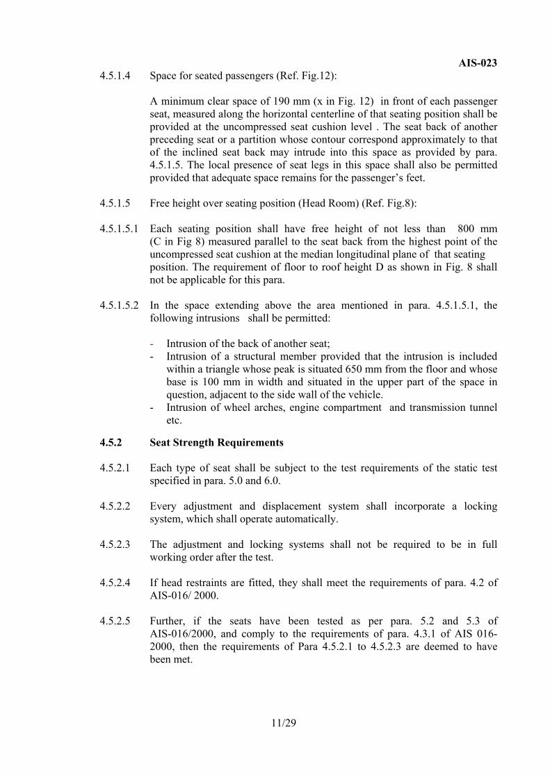
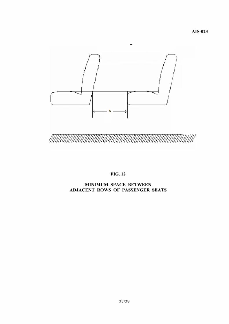
4.5.1.4 Space for seated passengers (Ref. Fig.12): A minimum clear space of 190 mm (x in Fig. 12) in front of each passenger
seat, measured along the horizontal centerline of that seating position shall be provided at the uncompressed seat cushion level . The seat back of another preceding seat or a partition whose contour correspond approximately to that of the inclined seat back may intrude into this space as provided by para. 4.5.1.5. The local presence of seat legs in this space shall also be permitted provided that adequate space remains for the passenger’s feet.
4.5.1.5 Free height over seating position (Head Room) (Ref. Fig.8): 4.5.1.5.1 Each seating position shall have free height of not less than 800 mm
(C in Fig 8) measured parallel to the seat back from the highest point of the uncompressed seat cushion at the median longitudinal plane of that seating position. The requirement of floor to roof height D as shown in Fig. 8 shall not be applicable for this para.
4.5.1.5.2 In the space extending above the area mentioned in para. 4.5.1.5.1, the
following intrusions shall be permitted: - Intrusion of the back of another seat; - Intrusion of a structural member provided that the intrusion is included
within a triangle whose peak is situated 650 mm from the floor and whose base is 100 mm in width and situated in the upper part of the space in question, adjacent to the side wall of the vehicle.
- Intrusion of wheel arches, engine compartment and transmission tunnel etc.
4.5.2 Seat Strength Requirements 4.5.2.1 Each type of seat shall be subject to the test requirements of the static test
specified in para. 5.0 and 6.0. 4.5.2.2 Every adjustment and displacement system shall incorporate a locking
system, which shall operate automatically. 4.5.2.3 The adjustment and locking systems shall not be required to be in full
working order after the test. 4.5.2.4 If head restraints are fitted, they shall meet the requirements of para. 4.2 of
AIS-016/ 2000. 4.5.2.5 Further, if the seats have been tested as per para. 5.2 and 5.3 of
AIS-016/2000, and comply to the requirements of para. 4.3.1 of AIS 016-2000, then the requirements of Para 4.5.2.1 to 4.5.2.3 are deemed to have been met.
11/29
AIS-028
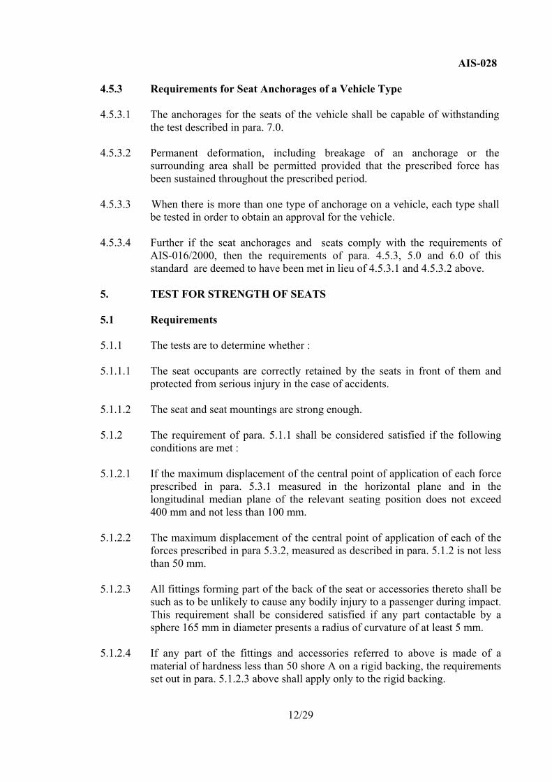
4.5.3 Requirements for Seat Anchorages of a Vehicle Type 4.5.3.1 The anchorages for the seats of the vehicle shall be capable of withstanding
the test described in para. 7.0.
4.5.3.2 Permanent deformation, including breakage of an anchorage or the surrounding area shall be permitted provided that the prescribed force has been sustained throughout the prescribed period.
4.5.3.3 When there is more than one type of anchorage on a vehicle, each type shall
be tested in order to obtain an approval for the vehicle. 4.5.3.4 Further if the seat anchorages and seats comply with the requirements of
AIS-016/2000, then the requirements of para. 4.5.3, 5.0 and 6.0 of this standard are deemed to have been met in lieu of 4.5.3.1 and 4.5.3.2 above.
5. TEST FOR STRENGTH OF SEATS 5.1 Requirements 5.1.1 The tests are to determine whether : 5.1.1.1 The seat occupants are correctly retained by the seats in front of them and
protected from serious injury in the case of accidents. 5.1.1.2 The seat and seat mountings are strong enough. 5.1.2 The requirement of para. 5.1.1 shall be considered satisfied if the following
conditions are met : 5.1.2.1 If the maximum displacement of the central point of application of each force
prescribed in para. 5.3.1 measured in the horizontal plane and in the longitudinal median plane of the relevant seating position does not exceed 400 mm and not less than 100 mm.
5.1.2.2 The maximum displacement of the central point of application of each of the
forces prescribed in para 5.3.2, measured as described in para. 5.1.2 is not less than 50 mm.
5.1.2.3 All fittings forming part of the back of the seat or accessories thereto shall be
such as to be unlikely to cause any bodily injury to a passenger during impact. This requirement shall be considered satisfied if any part contactable by a sphere 165 mm in diameter presents a radius of curvature of at least 5 mm.
5.1.2.4 If any part of the fittings and accessories referred to above is made of a
material of hardness less than 50 shore A on a rigid backing, the requirements set out in para. 5.1.2.3 above shall apply only to the rigid backing.
12/29
AIS-023
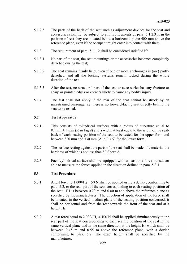
5.1.2.5 The parts of the back of the seat such as adjustment devices for the seat and
accessories shall not be subject to any requirements of para. 5.1.2.3 if in the position of rest they are situated below a horizontal plane 400 mm above the reference plane, even if the occupant might enter into contact with them.
5.1.3 The requirement of para. 5.1.1.2 shall be considered satisfied if : 5.1.3.1 No part of the seat, the seat mountings or the accessories becomes completely
detached during the test; 5.1.3.2 The seat remains firmly held, even if one or more anchorages is (are) partly
detached, and all the locking systems remain locked during the whole duration of the test;
5.1.3.3 After the test, no structural part of the seat or accessories has any fracture or
sharp or pointed edges or corners likely to cause any bodily injury. 5.1.4 The test shall not apply if the rear of the seat cannot be struck by an
unrestrained passenger i.e. there is no forward-facing seat directly behind the seat to be tested.
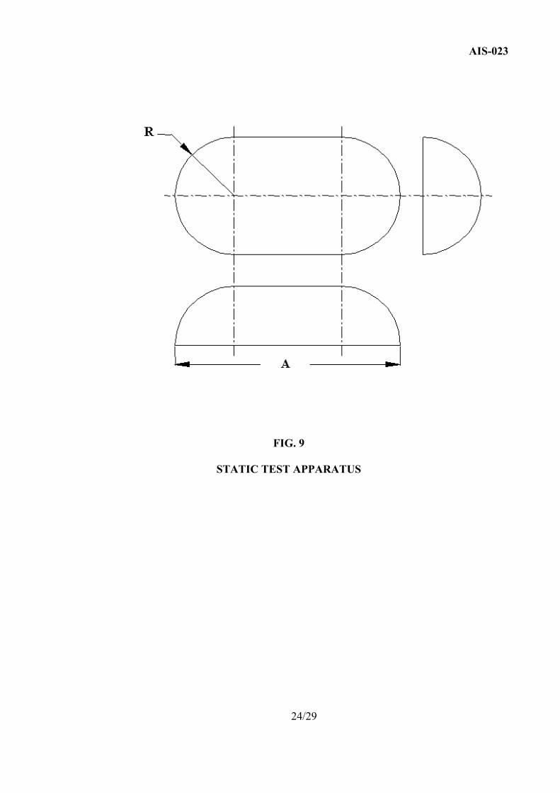
5.2 Test Apparatus 5.2.1. This consists of cylindrical surfaces with a radius of curvature equal to
82 mm ± 3 mm (R in Fig 9) and a width at least equal to the width of the seat-back of each seating position of the seat to be tested for the upper form and between 320 mm and 330 mm (A in Fig 9) for the lower form.
5.2.2 The surface resting against the parts of the seat shall be made of a material the
hardness of which is not less than 80 Shore A. 5.2.3 Each cylindrical surface shall be equipped with at least one force transducer
able to measure the forces applied in the direction defined in para. 5.3.1. 5.3 Test Procedure 5.3.1 A test force to 1,000/H1 ± 50 N shall be applied using a device, conforming to
para. 5.2, to the rear part of the seat corresponding to each seating position of the seat. H1 is between 0.70 m and 0.80 m and above the reference plane as specified by the manufacturer. The direction of application of the force shall be situated in the vertical median plane of the seating position concerned; it shall be horizontal and from the rear towards the front of the seat and at a height H1.
5.3.2 A test force equal to 2,000/ H2 ± 100 N shall be applied simultaneously to the
rear part of the seat corresponding to each seating position of the seat in the same vertical plane and in the same direction at the height H2 which shall be between 0.45 m and 0.55 m above the reference plane, with a device conforming to para. 5.2. The exact height shall be specified by the manufacturer.
13/29
AIS-023
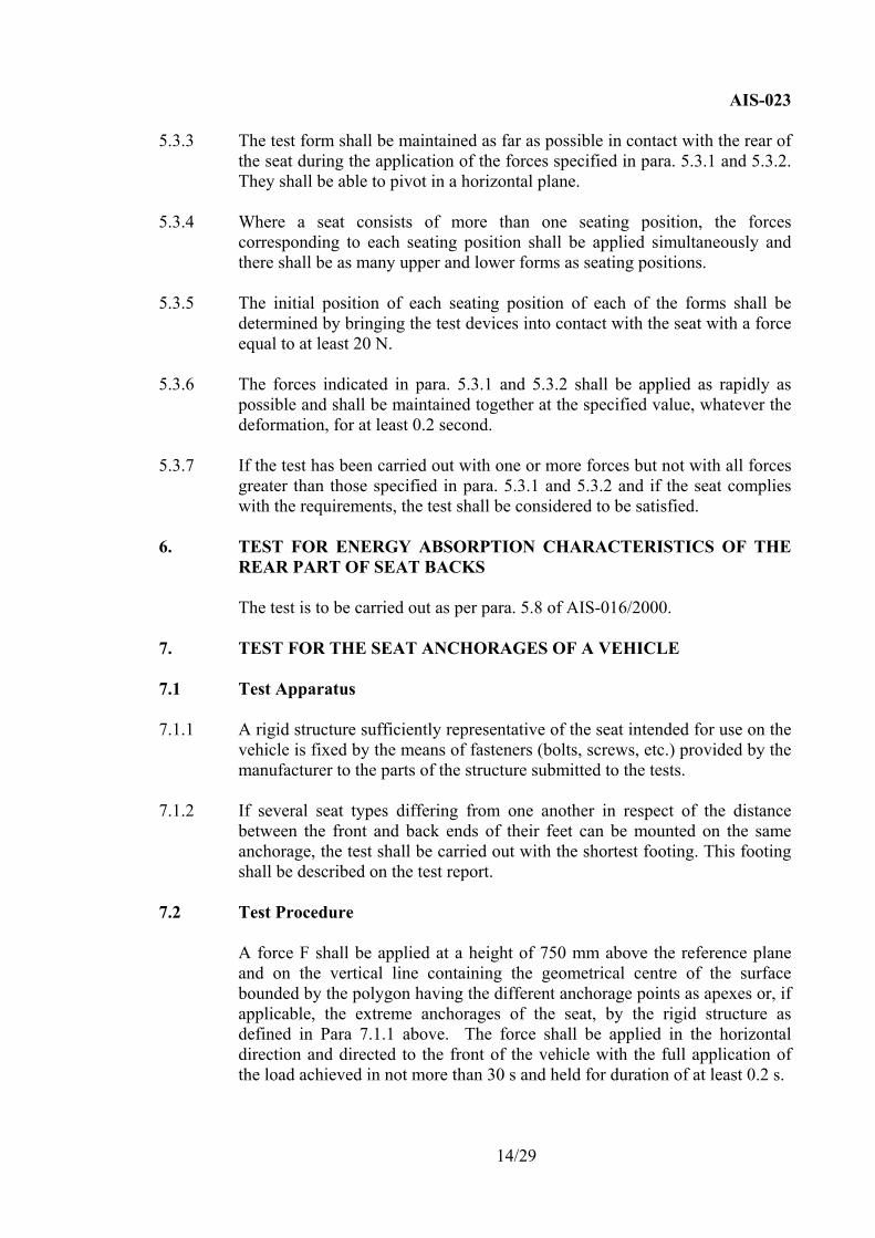
5.3.3 The test form shall be maintained as far as possible in contact with the rear of
the seat during the application of the forces specified in para. 5.3.1 and 5.3.2. They shall be able to pivot in a horizontal plane.
5.3.4 Where a seat consists of more than one seating position, the forces
corresponding to each seating position shall be applied simultaneously and there shall be as many upper and lower forms as seating positions.
5.3.5 The initial position of each seating position of each of the forms shall be
determined by bringing the test devices into contact with the seat with a force equal to at least 20 N.
5.3.6 The forces indicated in para. 5.3.1 and 5.3.2 shall be applied as rapidly as
possible and shall be maintained together at the specified value, whatever the deformation, for at least 0.2 second.
5.3.7 If the test has been carried out with one or more forces but not with all forces
greater than those specified in para. 5.3.1 and 5.3.2 and if the seat complies with the requirements, the test shall be considered to be satisfied.
6. TEST FOR ENERGY ABSORPTION CHARACTERISTICS OF THE
REAR PART OF SEAT BACKS The test is to be carried out as per para. 5.8 of AIS-016/2000. 7. TEST FOR THE SEAT ANCHORAGES OF A VEHICLE 7.1 Test Apparatus 7.1.1 A rigid structure sufficiently representative of the seat intended for use on the
vehicle is fixed by the means of fasteners (bolts, screws, etc.) provided by the manufacturer to the parts of the structure submitted to the tests.
7.1.2 If several seat types differing from one another in respect of the distance
between the front and back ends of their feet can be mounted on the same anchorage, the test shall be carried out with the shortest footing. This footing shall be described on the test report.
7.2 Test Procedure
A force F shall be applied at a height of 750 mm above the reference plane and on the vertical line containing the geometrical centre of the surface bounded by the polygon having the different anchorage points as apexes or, if applicable, the extreme anchorages of the seat, by the rigid structure as defined in Para 7.1.1 above. The force shall be applied in the horizontal direction and directed to the front of the vehicle with the full application of the load achieved in not more than 30 s and held for duration of at least 0.2 s.
14/29
AIS-023
The force F shall be determined by the following formula: F =(5000 ± 50) x i, where F is given in N and ‘i’ represents the number of seating positions of the seat as specified by the manufacturer.
15/29
AIS-023
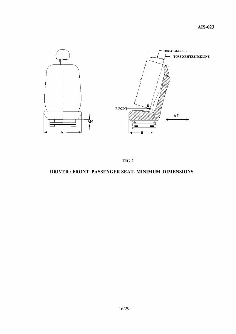
FIG.1
DRIVER / FRONT PASSENGER SEAT- MINIMUM DIMENSIONS
16/29
AIS-023
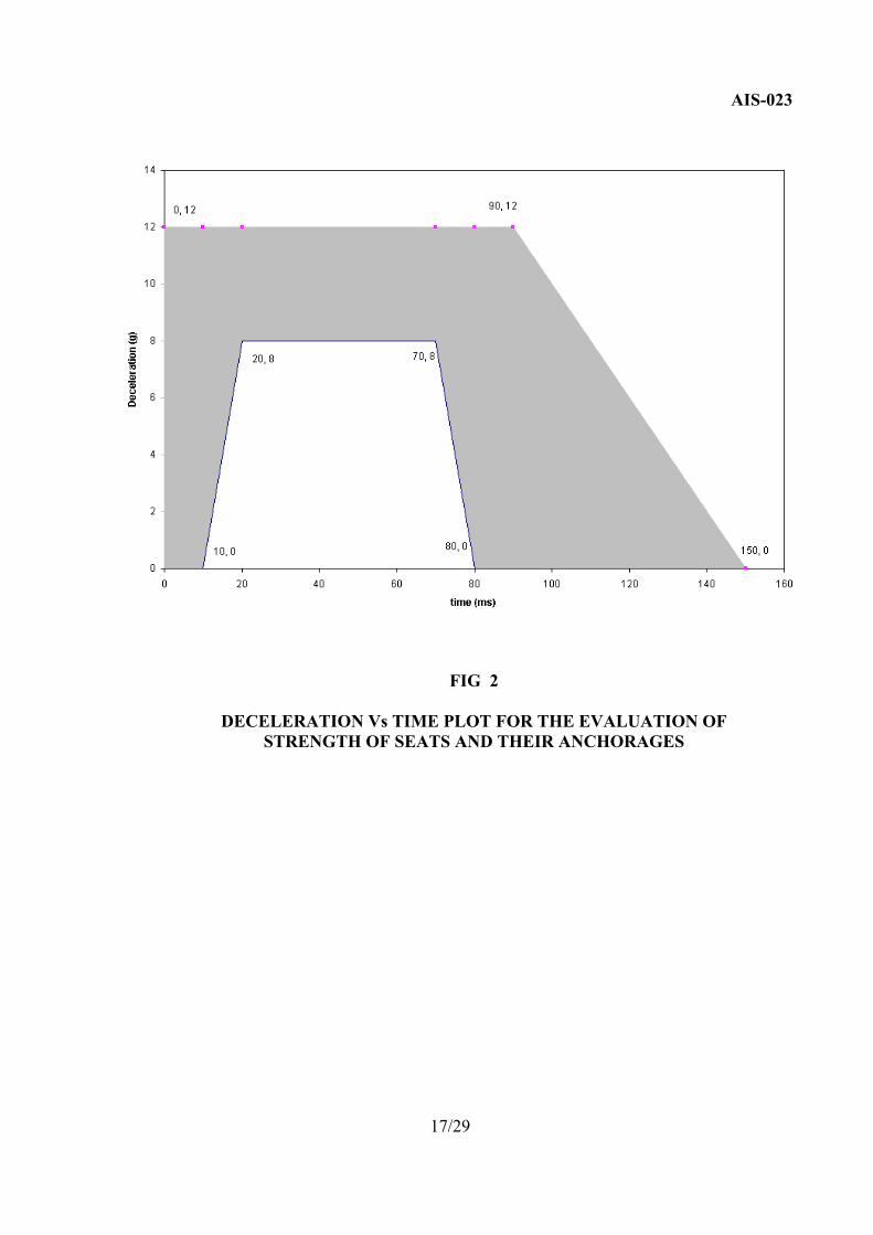
FIG 2
DECELERATION Vs TIME PLOT FOR THE EVALUATION OF
STRENGTH OF SEATS AND THEIR ANCHORAGES
17/29
AIS-023
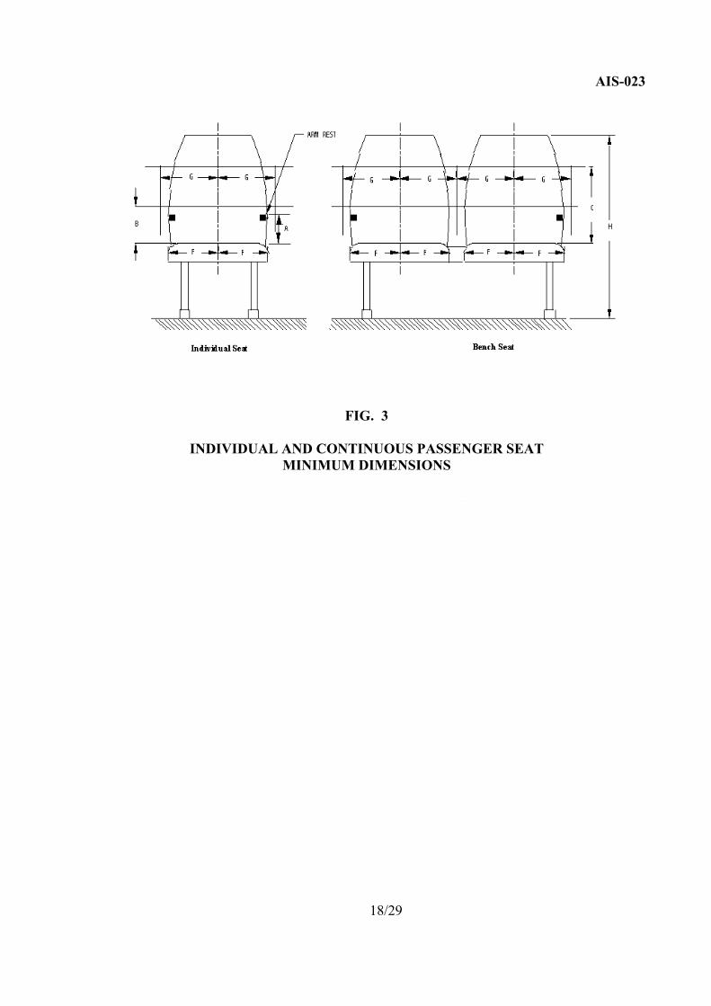
FIG. 3
INDIVIDUAL AND CONTINUOUS PASSENGER SEAT
MINIMUM DIMENSIONS
18/29
AIS-023
K
FIG. 4
DEPTH OF SEAT CUSHION 19/29
AIS-023
h
R POINTR
r
S
TORSO REFERENCE LINE
TORSO ANGLE α
HEIGHT
FIG. 5
MINIMUM TORSO ANGLE 20/29
AIS-023
FIG. 6
MINIMUM PITCH BETWEEN THE TWO ADJACENT ROWS OF THE SEAT
21/29
AIS-023
700 mm
850
mm
620
mm
600 mm
280 mm
550 mm
150m
m15
0mm
30° max-8° min
300mm
min
max
max
max
min
min
min
min
min
PLAN OF FLOOR
FIG. 7
PASSENGER SEAT SPACE FOR SEATED PASSENGER
22/29
AIS-023
FIG. 8
PERMITED INTRUSION OF A STRUCTURAL MEMBER
23/29
AIS-023
FIG. 9
STATIC TEST APPARATUS 24/29
AIS-023
FIG. 10
MINIMUM WIDTH OF SEAT CUSHION
25/29
AIS-023
FIG. 11
MINIMUM SPACE REQUIREMENT FOR FRONT PASSENGER SEAT OF GROUP B VEHICLES
26/29
AIS-023
FIG. 12
MINIMUM SPACE BETWEEN ADJACENT ROWS OF PASSENGER SEATS
27/29
AIS-023
ANNEXURE-I
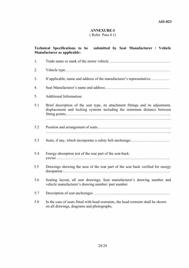
( Refer Para 4.1) Technical Specifications to be submitted by Seat Manufacturer / Vehicle Manufacturer as applicable: 1. Trade name or mark of the motor vehicle ………………………………………… 2. Vehicle type………………………………………………..……………………… 3. If applicable, name and address of the manufacturer’s representative…………… 4. Seat Manufacturer’s name and address…………………………………………… 5. Additional Information: 5.1 Brief description of the seat type, its attachment fittings and its adjustment,
displacement and locking systems including the minimum distance between fitting points:.………….…………………………………………………………...
……………………………………………………………………………………... 5.2 Position and arrangement of seats:………………………………………………… ……………………………………………………………………………………... 5.3 Seats, if any, which incorporate a safety belt anchorage:………………………… 5.4 Energy absorption test of the rear part of the seat-back: yes/no …………………………………………………………………………….. 5.5 Drawings showing the area of the rear part of the seat back verified for energy
dissipation :.……………………………………………………………………….. 5.6 Seating layout, all seat drawings, Seat manufacturer’s drawing number and
vehicle manufacturer’s drawing number/ part number. 5.7 Description of seat anchorages …………………………………………………… 5.8 In the case of seats fitted with head restraints, the head restraint shall be shown
on all drawings, diagrams and photographs.
28/29
AIS-023
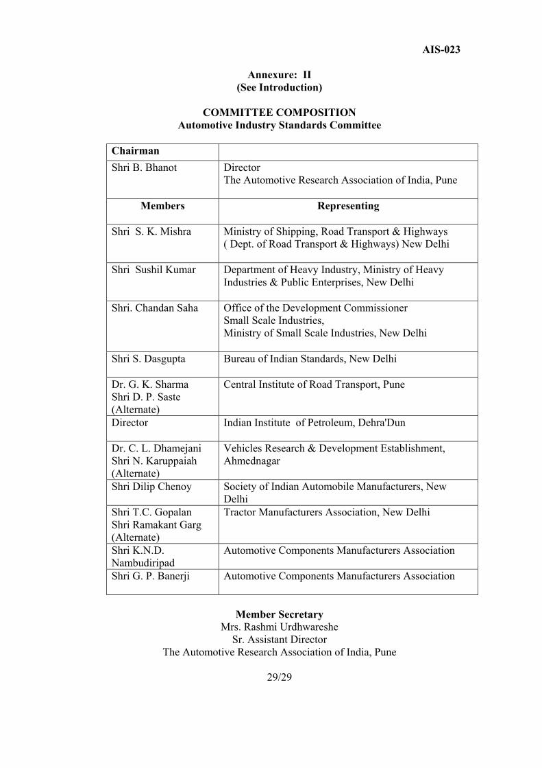
Annexure: II (See Introduction)
COMMITTEE COMPOSITION
Automotive Industry Standards Committee
Chairman Shri B. Bhanot Director
The Automotive Research Association of India, Pune
Members Representing
Shri S. K. Mishra Ministry of Shipping, Road Transport & Highways ( Dept. of Road Transport & Highways) New Delhi
Shri Sushil Kumar Department of Heavy Industry, Ministry of Heavy Industries & Public Enterprises, New Delhi
Shri. Chandan Saha Office of the Development Commissioner Small Scale Industries, Ministry of Small Scale Industries, New Delhi
Shri S. Dasgupta Bureau of Indian Standards, New Delhi
Dr. G. K. Sharma Shri D. P. Saste (Alternate)
Central Institute of Road Transport, Pune
Director
Indian Institute of Petroleum, Dehra'Dun
Dr. C. L. Dhamejani Shri N. Karuppaiah (Alternate)
Vehicles Research & Development Establishment, Ahmednagar
Shri Dilip Chenoy
Society of Indian Automobile Manufacturers, New Delhi
Shri T.C. Gopalan Shri Ramakant Garg (Alternate)
Tractor Manufacturers Association, New Delhi
Shri K.N.D. Nambudiripad
Automotive Components Manufacturers Association
Shri G. P. Banerji Automotive Components Manufacturers Association
Member Secretary
Mrs. Rashmi Urdhwareshe Sr. Assistant Director
The Automotive Research Association of India, Pune