Licence: L5008/1991/13 File No: 2010/005964 1 Licence Number L5008/1991/13 Licence Holders Mr Errol John Howard Mrs Annette Rose Howard Registered business address 310 Wannamal Road Mindarra WA 6503 Date of amendment 21 February 2017 Prescribed Premises Category 2: Intensive piggery Premises Kamarah Piggery 310 West Wannamal Road Mindarra WA 6503 Lot 21 on Plan 74381 Certificate of Title Volume 2807 Folio 573 Amendment The Chief Executive Officer (CEO) of the Department of Environment Regulation (DER) has amended the above licence in accordance with section 59 of the Environmental Protection Act 1986 as set out in this Amendment Notice. Date signed: 21 February 2017 Jonathan Bailes A/SENIOR MANAGER - INDUSTRY REGULATION an officer delegated under section 20 of the Environmental Protection Act 1986 (WA) Amendment Notice 1
Transcript
Licence: L5008/1991/13 File No: 2010/005964 1
Licence Number L5008/1991/13
Licence Holders Mr Errol John Howard
Mrs Annette Rose Howard
Registered business address
310 Wannamal Road
Mindarra WA 6503
Date of amendment 21 February 2017
Prescribed Premises Category 2: Intensive piggery
Premises Kamarah Piggery
310 West Wannamal Road
Mindarra WA 6503
Lot 21 on Plan 74381
Certificate of Title Volume 2807 Folio 573
Amendment
The Chief Executive Officer (CEO) of the Department of Environment Regulation (DER) has amended the above licence in accordance with section 59 of the Environmental Protection Act 1986 as set out in this Amendment Notice.
Date signed: 21 February 2017
Jonathan Bailes
A/SENIOR MANAGER - INDUSTRY REGULATION
an officer delegated under section 20 of the Environmental Protection Act 1986 (WA)
Amendment Notice 1
Licence: L5008/1991/13 File No: 2010/005964 2
Amendment Notice
This notice is issued under section 59 of the Environmental Protection Act 1986 (EP Act) to amend the licence issued under the EP Act for prescribed premises as set out below. This notice of amendment is given under section 59B(9) of the EP Act.
Amendment Description
An application for licence amendment was received from Mr Errol John Howard and Mrs Annette Rose Howard (Licensee) on 15 June 2016 for works associated with an expansion of the intensive piggery to 21,888 animals, equivalent to 25,384 Standard Pig Units (SPU). This notice is accompanied by a Decision Report which documents the assessment and determination of the application in accordance with DER’s published Regulatory Framework.
Decision
The licence amendment application has been determined by amending the conditions of the licence as set out below. The Decision Report attached to this notice sets out the Delegated Officer’s decision making in accordance with DER’s Guidance Statement: Decision Making and Guidance Statement: Risk Assessment.
Amendment History
Instrument Issued Amendment
L5008/1991/13 29/04/2016 Amendment by notice to extend licence duration.
L5008/1991/13 21/02/2017 Amendment Notice 1
Works associated with an increase of design capacity to 21,888 animals
Amendment 1. Condition 1.1.2 of the licence is amended by the insertion of the red text shown
in underline below:
“AS1289.3.1.2” means the Australian Standard AS 1289.3.1.2 Methods of testing soils for engineering purposes - Soil classification tests - Determination of the liquid limit of a soil - One point Casagrande method (subsidiary method).
“AS 1289.3.3.1” means the Australian Standard AS 1289.3.3.1 Methods of testing soils for engineering purposes - Soil classification tests - Calculation of the plasticity index of a soil.
“AS 1289.3.6.1” means the Australian Standard AS 1289.3.6.1 Methods of testing soils for engineering purposes - Soil classification tests - Determination of the particle size distribution of a soil - Standard method of analysis by sieving.
“AS 1289.3.8.1” means the Australian Standard AS 1289.3.8.1 Methods of testing soils for engineering purposes – Soil classification tests – Dispersion - Determination of Emerson class number of a soil.
Licence: L5008/1991/13 File No: 2010/005964 3
“AS 1289.5.2.1” means the Australian Standard AS 1289.5.2.1 Methods of testing soils for engineering purposes - Soil compaction and density tests - Determination of the dry density/moisture content relation of a soil using modified compactive effort.
“AS 1289.5.4.1” means the Australian Standard AS 5.4.1 Methods of testing soils for engineering purposes - Soil compaction and density tests - Compaction control test - Dry density ratio, moisture variation and moisture ratio.
“CEO” for the purposes of notification means:
Director General Department Administering the Environmental Protection Act 1986 Locked Bag 33 Cloisters Square PERTH WA 6850 [email protected]
“Effluent” means the liquid waste stream generated by the conventional sheds comprising of wastewater, spilt/leaked drinking water, manure and waste feed.
“PVC” means polyvinyl chloride.
“SPU” means Standard Pig Unit and has the same meaning as defined in the National Environmental Guidelines for Piggeries – Second Edition 2010, Australian Pork Limited.
2. The licence is amended by the insertion of the following conditions 6.1.1 and 6.2.1 to 6.2.5: 6 Works 6.1 Location of Works 6.1.1 The licensee must locate the Works generally in accordance with the
Site Plans in Schedule 3 to this licence. 6.2 Infrastructure Design and Construction Requirements 6.2.1 The licensee must carry out the Works within the Premises in
accordance with the requirements set out in Schedule 4 to this Licence.
6.2.2 Subject to condition 6.2.4, at least 10 business days prior to the commencement of the Works, the Licensee must provide the CEO engineering or building certification from a suitable qualified professional confirming that the detailed construction drawings and plans for the Works include each item of infrastructure or component of infrastructure specified in column 1 with the requirements specified in column 2, as set out in Table 6.2.1 below.
6.2.3 Subject to condition 6.2.4, on completion of the Works, the Licensee
must provide the CEO engineering or building certification from a suitably qualified professional confirming each item of infrastructure or component of infrastructure specified in column 1 with the requirements specified in column 2, as set out in Table 6.2.1 below have been constructed with no material defects.
Licence: L5008/1991/13 File No: 2010/005964 4
6.2.4 The licensee must not depart from the requirements specified in column 2 of Table 6.2.1 except: (a) where such departure is minor in nature and does not materially
change or affect the infrastructure; or (b) where such departure improves the functionality of the
infrastructure and does not increase risks to public health, public amenity or the environment;
and all other conditions of this Licence are still satisfied. 6.2.5 If condition 6.2.4 applies, then the Licensee must provide the CEO with a
list of departures which are certified as complying with condition 6.2.4 at the same times, and from the same professional, as the certifications required under conditions 6.2.2 and 6.2.3.
Table 6.2.1: Infrastructure design and construction requirements
Column 1 Column 2
Infrastructure Requirements (design and construction)
Conventional sheds
(a) All sheds must have concrete pits underneath to enable pull-plug effluent management system.
(b) All sheds must comprise of concrete and partially slatted floors.
(c) All sheds must be designed to enable the use of wastewater from the facultative pond for flushing.
(d) All underfloor pits must direct effluent to the anaerobic ponds via the fan separator.
(e) Stormwater runoff, including from roofs, is to be directed away from all sheds.
(f) All sheds must be separated by a distance of at least five times their height to maximise ventilation.
Eco shelters All eco shelters must have a concrete floor with bunded sides to contain bedding material.
Composting bunkers
(a) Bunkers must be 10 m long, 3 m wide and 2.4 m deep.
(b) Bunkers must have a roof to prevent the ingress of rainfall.
(c) Bunkers must have a hardstand concrete floor and three concrete sites with a front access gate.
(d) The hardstand concrete floor must prevent stormwater runoff entering the bunker.
Fan separator and solids collection bunker
The bunker must:
(a) be located underneath for the capture of fan separated solids;
(b) have a concrete floor and sides to contained solids;
(c) have a roof to prevent the ingress of rainfall.
Licence: L5008/1991/13 File No: 2010/005964 5
Column 1 Column 2
Infrastructure Requirements (design and construction)
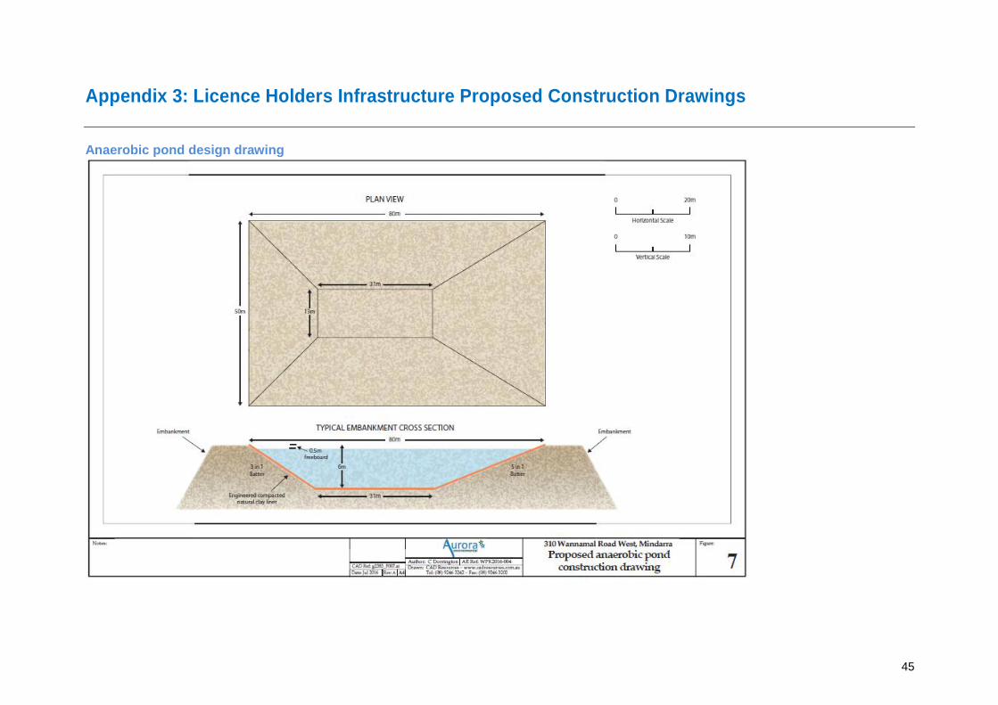
Anaerobic Pond (a) Designed and construction to the dimensions specified in the Schedule 1: Anaerobic pond drawing.
(b) Embankments designed and constructed to prevent erosion as a result of stormwater runoff.
(c) Designed to allow access for desludging
(d) A clay liner must meet the following specification:
(i) Minimum 150 mm subgrade preparation to provide a sound and stable base for liner construction. Subgrade preparation must include compaction until no rutting or pumping is observed.
(ii) Soils used for the liner must be free from plant roots and reactive, soluble and organic matter;
(iii) The liner material must meet the following criteria a. percentage fines with acceptability of:
i. more than 25 percent passing a 75-micron sieve;
ii. more than 15 percent passing a 2-micron sieve, tested using AS 1289 3.6.1;
iii. liquid limit with acceptability of 30 to 70 percent tested using AS 1289 3.1.2;
iv. plasticity index with acceptability of more than 15, tested using method AS 1289 3.3.1; and
v. Emerson class number with acceptability of 5 to 6 tested using AS 1289 3.8.1.
(e) The liner material must be homogeneous in nature and properties, with no sandy patches exceeding the liner specification or rocks retained on a 37.5mm sieve.
(f) The liner must be installed in at least two layers of equal thickness to ensure adequate compaction is achieved and be moisture-conditioned to achieve the maximum design soil density exceeding the 95 percent maximum (in place) dry density (MDD) determined using AS 1289 .5.2.1 and AS 12895.4.1.
(g) The minimum thickness of the compacted soil liner should be 300 mm with a tolerance of 5mm.
(h) The compacted liner must uniformly cover both the base and perimeter of the pond to achieve one integrated holding pond.
(i) The preparation and construction of the pond subgrade and liner must be supervised by a competent and experienced geotechnical professional.
(j) The liner must be certified in accordance with section 17 (Liner certification) of Water Quality Protection Note 27 – Liners for containing pollutants, using engineered soils, Western Australian Department of Water (August 2013).
(k) A minimum 300mm thickness layer of inert granular or gravel material is to cover the liner at the base of the pond to protect the liner during desludging. The cover must be applied in a manner that does not damage the lining and allows access for machines to desludge the lagoon without damage to the liner.
Licence: L5008/1991/13 File No: 2010/005964 6
Column 1 Column 2
Infrastructure Requirements (design and construction)
Effluent transfer pipelines
Effluent pipelines from the proposed conventional sheds to the anaerobic ponds via the fan separator are to be impermeable PVC piping.
3. The licence is amended by the insertion of Schedule 3: Works Maps and Drawings in this notice.
4. The licence is amended by the insertion of Schedule 4: Works in this notice.
Licence: L5008/1991/13 File No: 2010/005964 7
Schedule 3: Works Maps and Drawings
General layout map
The general layout of existing and to be constructed infrastructure is shown in the map below.
Licence: L5008/1991/13 File No: 2010/005964 8
Anaerobic pond construction drawing
The design for the additional anaerobic pond to be constructed is shown in the drawing below.
Licence: L5008/1991/13 File No: 2010/005964 9
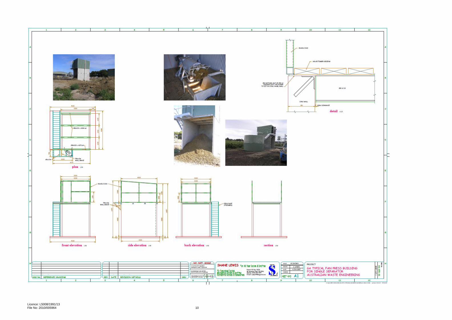
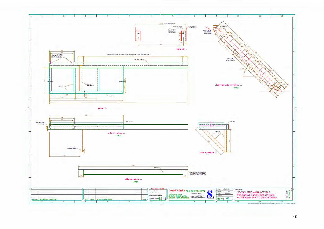
Fan separator and collection bunker drawings The design for the fan separator and collection bunker to be constructed is shown in the following three drawings
Licence: L5008/1991/13 File No: 2010/005964 10
Licence: L5008/1991/13 File No: 2010/005964 11
Licence: L5008/1991/13 File No: 2010/005964 12
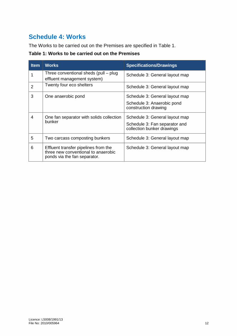
Schedule 4: Works
The Works to be carried out on the Premises are specified in Table 1.
Table 1: Works to be carried out on the Premises
Item Works Specifications/Drawings
1 Three conventional sheds (pull – plug
effluent management system) Schedule 3: General layout map
2 Twenty four eco shelters Schedule 3: General layout map
3 One anaerobic pond Schedule 3: General layout map
Schedule 3: Anaerobic pond construction drawing
4 One fan separator with solids collection bunker
Schedule 3: General layout map
Schedule 3: Fan separator and collection bunker drawings
5 Two carcass composting bunkers Schedule 3: General layout map
6 Effluent transfer pipelines from the three new conventional to anaerobic ponds via the fan separator.
Schedule 3: General layout map
i
Application for Licence Amendment
Division 3, Part V Environmental Protection Act 1986
Licence Holders: Mr Errol John Howard and Mrs Annette Rose Howard
ABN: 86 822 886 415
Licence Number:
L5008/1991/13
File Number: 2010/002610
Premises: Kamarah Piggery
310 Wannamal Road MINDARRA WA 6503
Lot 21 on Plan 74381 Certificate of Title Volume 2807 Folio 573
Date of report: Tuesday, 21 February 2017
Status of Report Final
Decision Report
ii
Table of Contents
Definitions of terms and acronyms .......................................................................... iv
1. Purpose and Scope of Assessment .................................................................. 1
5.1 Planning Approval .................................................................................................. 8 5.2 Applicable Regulations, Standards and Guidelines ................................................ 9 5.3 Part V of the EP Act ............................................................................................... 9
9.1 Summary of Controls ............................................................................................ 33 9.2 Infrastructure Design or Construction Requirements ............................................ 33
9.3 Requirements for Ongoing Operation of Infrastructure ......................................... 36 9.3.1 Controls for odour ..................................................................................... 36 9.3.2 Controls to minimise discharges to land ................................................... 38 9.3.3 Controls to minimise seepage .................................................................. 39
9.4 Solid Waste Application to Land ........................................................................... 39 9.4.1 Eco shelter spent bedding ........................................................................ 39
Premises as defined in the EP Act, means residential, industrial or other premises of any kind whatsoever and includes land, water and equipment
Prescribed Premises
premises of the types listed in Schedule 1 of the EP Regs.
Primary activities has the meaning in point 8 of DER’s published Guidance Statement: Risk Assessments
REW Resource enhancement wetland
RIWI Act Rights in Water and Irrigation Act 1914
v
Term Definition
SPU Standard Pig Unit. “A unit for defining piggery capacity based on by-products output. The manure and waste feed produced by one SPU, contains the amount of volatile solids (VS) typically produced by an average size grower pig (90 kg VS/yr). SPU multipliers for other pig classes are based on their comparative VS production.”
TEC Threatened ecological community
WQPN 27 Water Quality Protection Note 27: Liners for containing pollutants, using engineered soils, Department of Water, 2013.
WNMP the report Kamarah Piggery Expansion Waste & Nutrient Management Plan 310 Wannamal road West Mindarra, WA, Aurora environmental, 2 February 2017
List of Figures
Figure 1: Site layout of current and proposed infrastructure (from the Application) Figure 2: Kamarah Piggery location Figure 3: Aerial image of the closest residential premises to Kamarah Piggery Figure 4: Aerial image of Kamarah Piggery and distances to closest sensitive receptors Figure 5: Location of Conservation, Resource Enhancement and Multiple Use Category wetlands Figure 6: Mean temperature and rainfall for Gingin Aero Figure 7: Wind roses for Wannamal
List of Tables
Table 1: Prescribed Premises Category Table 2: Summary of site history (from the Application) Table 3: Kamarah Piggery Category 2 existing infrastructure Table 4: Kamarah Piggery Category 2 proposed infrastructure Table 5: Proposed stock numbers (from the Application) Table 6: Wastewater treatment system components (from the Application) Table 7: Summary of waste management and disposal Table 8: Separation distances Table 9: Receptors and distance from prescribed activity Table 10: S-Factor calculations Table 11: Summary of S-Factor and measured distances to sensitive receptors Table 12: Specified ecosystems Table 13: Groundwater and water sources Table 14: Identification of key emissions during construction Table 15 : Identification of key emissions during operation Table 16 : Risk Criteria Table 17: Risk Treatment Table 18: Licence Holders controls for odour emissions Table 19: Potential sources of wastewater and leachate discharges to land Table 20: Characteristics of piggery pond irrigation effluent (as sourced from Table 14.1 in the NEGP) Table 21: Characteristics of in situ piggery pond sludge (as sourced from Table 14.2 in the NEGP) Table 22: Licence Holders controls for discharges to land Table 23: Licence Holders controls for seepage from wastewater treatment ponds Table 24: Risk rating of emissions
1
1. Purpose and Scope of Assessment
An application to amend Licence L5008/1991/13 (the Application) was lodged on 15 June 2016 by the Licence Holders of the Kamarah Piggery (Category 2: Intensive piggery) located at West Wannamal Road, Mindarra. The Licence Holders propose works to expand the capacity of the piggery from its current holding of 9,250 animals to 21,888 animals (25,384 SPU). The piggery is a grower facility raising pigs bred on other sites.
The Licence Holders are seeking approval under the provisions of the EP Act for construction and operation of three conventional piggery sheds (pull-plug), 24 eco shelters, and associated supporting infrastructure.
The assessment of the Application has been undertaken in accordance with DER’s published Regulatory Framework. The scope of assessment includes:
assessment of the design of the proposed works;
a risk-based assessment of the emissions and discharges to the environment that may occur at the construction stage; and
a risk-based assessment of the emissions and discharges associated with the operation of the expanded capacity (25,384 SPU).
The Delegated Officer has given effect to determined conditions for the construction phase of the works through an Amendment Notice. The Amendment Notice does not authorise an increase beyond the currently approved capacity and does not authorise emissions and discharges in respect of operating the proposed infrastructure and equipment once constructed. The Delegated Officer has proposed controls in sections 9.3, 9.4 and 9.5 of this Decision Report that will be applied to a revised licence, if granted, once works are complete and the Licence Holders have complied with the conditions of the Amendment Notice.
2. Background
The existing Licence L5008/1991/13 is for an intensive piggery as described in Table 1 below. The Licence Holders are both the owners and occupiers of the premises.
Table 1: Prescribed Premises Category
Classification of Premises
Description Current Production Capacity
(from existing licence)
Proposed Production Capacity
(from the Application)
Schedule 1 Category Threshold
Category 2 Intensive piggery: premises on which pigs are fed, watered and housed in pens.
4,500 animals1 21,888 animals
(25,384 SPU)2
1,000 animals or more
Note 1: Does not account for 4,750 animals held in eco shelters. Note 2: Accounts for proposed capacity including existing and proposed numbers held in eco shelters.
Section 2.1 (page 3) of the Application provides a description of the site history which has been summarised in Table 2.
2
Table 2: Summary of site history (from the Application)
Date Event
1980 Land purchased by occupiers
1986 – 1992 Piggery constructed comprising eight conventional sheds and the wastewater treatment system
2001 19 domed eco shelters constructed
2012 Four domed eco shelters constructed
January 2016 Approx. 4,000 animals housed in conventional sheds with an additional 4,750 housed in eco shelters
Licence L5008/1991/13 specifies a production or design capacity of 4,500 animals. The Delegated Officer noted that the premises have existing eco shelters with capacity for 4,750 animals which are not described in the assessed capacity. The Delegated Officer also noted the Application includes the construction of 24 new eco shelters increasing the total capacity to 11,600 animals in eco shelters.
The description of category 2 in Schedule 1 of the EP Regs details premises on which pigs are fed, watered, and housed in pens. The Delegated Officer had regard to DER’s published Guidance Statement: Risk Assessments and considered that pigs to be held in the proposed and existing eco shelters are primary activities which may be subject to conditions in the amended licence that grants approval for the Application. The scope of the assessment, therefore, includes animals held and to be held in conventional sheds and eco shelters.
The assessment will be based on the maximum number of SPU proposed to be held on the premises at any one time.
3. Proposal
The Licence Holders lodged an application for a licence amendment on 15 June 2016.
The Licence Holders amended the application on 11 July 2016 upon a request for additional information from the Delegated Officer. The revised application and the additional supporting information were accepted by the Delegated Officer for assessment.
The following additional documents and supporting information were provided to the Delegated Officer in further support of the Application lodged on 15 June:
Application Form dated 11 July;
A letter on behalf of the Licence Holders by Aurora Environmental dated 15 July 2016 in response to specific questions raised by the Delegated Officer on 4 July 2016; and
A proposal document Kamarah Piggery Expansion Licence Amendment Application 310 Wannamal Road West, Mindarra WA, on behalf of the Licence Holders by Aurora Environmental dated 15 July 2016—including ten appendices.
4. Overview of Kamarah Piggery
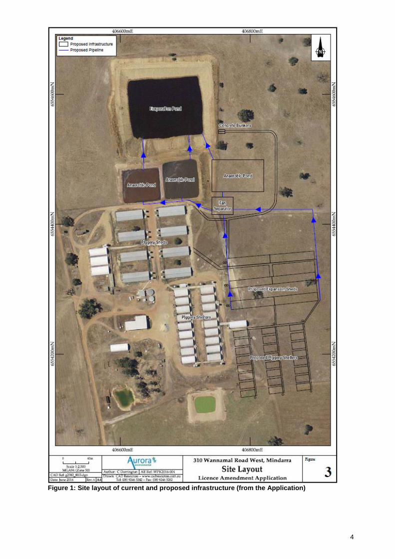
4.1 Infrastructure
The existing and proposed infrastructure at the Kamarah Piggery is detailed in Table 3 and Table 4. A site layout of existing and proposed infrastructure is shown in Figure 1.
Proposed design and construction notes (from the Application)
Reference
1 3 x conventional sheds (pull-plug drainage system)
Partly slatted concrete floor;
Under floor pits to collect spilt feed, water, urine and faeces;
Pull-plug flush system using clean or recycled water; and
Drainage system
Figure 1
2 1 x Fan (screw press) separator with concrete bunker/solids collection area
Fan (screw press) separator with a concrete bunker/solids collection area under the screw press to capture separated solids;
Liquid from the fan separator directed to the anaerobic ponds.
3 24 x eco shelters Steel domed framework;
High tensile fabric positioned over the steel; and
Concrete footings and a concrete floor.
4 1 x anaerobic pond
Liner and walls constructed using in situ clays;
Clay to be excavated from the centre of the pond to a depth of 6m, and walls pushed up using earthmoving equipment;
Clay at the base and sides of the pond will be compacted using a padfoot roller to a minimum thickness of 300 mm with a target compaction maximum dry density of 1.90 t/m
3 and optimum moisture content of 14%;
Maximum dry density greater than 98% and resultant compacted in-situ permeability of the clay liner being less than 10
-9 m/s;
Verification testing in accordance with AS 1289.6.7.1 (2001) to validate the liner permeability meets the criteria and testing regime in Water Quality Protection Note 27: Liners for containing pollutants, using engineered soils, Department of Water, 2013; and
Refer to Appendix 3 – Map of new anaerobic pond design
5 2 x concrete carcass composting bunkers
Dimensions 10m long by 3m wide by 2.4m deep and covered with a colorbond steel roof;
Layering of straw/sawdust, pig carcasses and covered with used straw from eco shelters and manure;
Rotation of bunkers; and
Estimated compost production of 600 – 700 tonnes per year.
4
Figure 1: Site layout of current and proposed infrastructure (from the Application)
5
4.2 Operational Aspects
Kamarah Piggery is a grower facility which accepts pigs aged from three weeks (weaners) and grows them out until approximately 22 weeks of age (grower/finishers). The Licence Holders propose to build additional eco shelters and conventional sheds to increase the size of the piggery.
The Application contained a table with the existing and proposed animal numbers, converted to SPU. This table is extracted and shown below in Table 5.
Table 5: Proposed stock numbers (from the Application)
Pig Class1
SPU Factor1
Stock Housing
Number of animals
SPU
Weaners 0.5 7,649 3,825 Eco shelters
Porkers 1.0 3,604 3,604 Eco shelters
Growers 1.6 5,941 9,506 Conventional Sheds
Finishers 1.8 4,694 8,449 Conventional Sheds
Total 21,888 25,384
Note 1: Refer to Section 4.3 of NEGP for further explanation of SPU and SPU factors
The existing conventional sheds are naturally ventilated with concrete floors, which are manually hosed to flush accumulated manure into drains and to the two anaerobic ponds. Wastewater from the anaerobic ponds is directed to a final facultative/evaporation pond. The proposed new conventional sheds will also be a pull-plug design, similar to the existing conventional sheds. Manure falls through slatted floors into underfloor pits and is released on rotation every one to four weeks.
Wastewater will be re-directed from the existing and proposed conventional sheds through a new solids separator to reduce the solids loading to the anaerobic ponds.
Eco shelters (also known as a deep litter housing system) are a series of hooped metal frames covered in a waterproof fabric over concrete floors. Pigs are bedded on straw to absorb manure and spent bedding is replaced on a 12-week basis.
Current and altered operational aspects of waste management for the premises include:
Effluent treatment via anaerobic ponds and disposal via facultative/evaporation pond or reuse for flushing of new conventional sheds;
Piggery solids and sludge contained on a bunded hardstand with return leachate to the anaerobic ponds;
Spent bedding from eco shelters will be applied to land (onsite paddocks);
Carcass disposal to be altered from burial to composting;
Solid waste is to be partially removed from wastewater prior to entering the anaerobic ponds; and
Screened solid waste and waste from composted carcasses will be periodically removed from site by a third party.
6
4.2.1 Solid waste management from eco shelters
The Licence Holders remove bedding from eco shelters using a mechanical loader and the material is placed directly into a spreader. The material is preferentially spread on paddocks used for cropping, where nutrients will be absorbed by crops. The balance of material is placed on pasture paddocks. The Licence Holders state that the paddocks that receive spend bedding are not fertilised with any other nutrient source.
The Application states that currently 30m3 of bedding is cleaned from each of the existing eco-shelters. Three eco-shelters are cleaned out per fortnight meaning all 19 shelters (current eco-shelters) are cleaned out every 12 weeks. The current total volume of bedding removed is approximately 570m3 every 12 weeks. The rate of application of spent bedding material is 15m3 per hectare, and the approximate area available for spreading is 571 ha, which excludes tree stands and wetland areas. Every 12 weeks, spreading occurs across a 38ha area.
The Licence Holders have advised that approximately 33.5m3 of bedding will be cleaned-out from each new eco shelter (with four eco shelters cleaned-out per fortnight), in addition to the 30m3 from each of the existing eco shelters (three eco shelters cleaned per fortnight). Therefore, every 12 weeks there will be a total of 1380m3 of bedding to be spread over 92ha, at the same application rate (15m3/ha). Given the total area of land available for spreading, 74 weeks will elapse before bedding is reapplied to the same area of land.
As part of comments on the draft Amendment Notice and Decision Report, the Delegated Officer requested the Licence Holders provide a descriptive map of areas to which spent bedding may be applied. The Delegated Officer also requested a nutrient balance for the application of spent bedding to land. The Licence Holders provided a copy of the report Kamarah Piggery Expansion Waste & Nutrient Management Plan 310 Wannamal road West Mindarra, WA, Aurora environmental, 2 February 2017 (WNMP) to address this request. The WNMP was prepared to address conditions of the Shire of Gingin planning approval outlined in section 5.1.
Figure 5 of the WNMP provides a map depicting spent bedding land application areas which the executive summary states are 571 ha or 38.4% of the entire property. The Licence Holders propose to split the application area into three approximate 180 ha areas to be used alternatively over a three-year cycle. The Delegated Officer is satisfied that the WNMP demonstrates that the area stated in the Application is available and notes that it incorporates separation distances that are consistent with proposed controls in section 9.4.1.
4.2.2 Wastewater treatment system - overview
The existing and proposed wastewater treatment system are summarised in Table 6.
Table 6: Wastewater treatment system components (from the Application)
Component Existing Treatment System Proposed Combined Treatment System
Solids screen and concrete collection bunker (new)
- Screw Press Fan Separator with concrete collection bunker
Anaerobic Pond 1 50m x 50m x 10m (min) (9,132m
3)
50m x 50m x 10m (min)
unchanged
Anaerobic Pond 2 50m x 50m x 10m (min)
(9,132m3)
50m x 50m x 10m (min)
unchanged
Anaerobic Pond 3 (new) - 50m x 80m x 6m (min)
New (10,914m3)
Facultative/Evaporation Pond 140m x 160m x 6m (min) 140m x 160m x 6m (min)
7
The Delegated Officer noted the existing pond that is referred to as a facultative/evaporation pond is considered to be acting as a treatment pond rather than just an evaporative pond given its depth is 6m. Evaporation ponds are normally shallow with a large surface area. This pond hereafter is referred to as a facultative pond.
The Licence Holders modelled the waste and wastewater generation from the proposed expanded piggery using PigBal v4.090.
4.2.3 Waste water treatment system – water balance
The Application contained a water balance to assess the volumetric capacity of the wastewater treatment system (new pond included). The water balance indicated that the facultative pond would fill to within 1m of the top of its embankment after approximately 3.5 years. Once full, the Licence Holders propose to reuse treated wastewater for flushing the effluent pits in the pull-plug design conventional sheds. The Delegated Officer was satisfied that the wastewater treatment system has enough capacity, provided that wastewater is reused as proposed. The Delegated Officer noted that irrigation of wastewater is not proposed or needed to maintain enough capacity for high rainfall events.
4.2.4 Waste water treatment system – anaerobic pond capacity
The Licence Holders provided design calculations for the size of the anaerobic pond, sufficient to maintain adequate treatment capacity. The Delegated Officer accepted the proposed size of the third pond to be built (10,914m3). However, the Application proposes to have one pond in service at any one time with the other two ponds being out of service for desludging and maintenance. As such, the duty service of the active pond is limited by its capacity to about 12 months of continuous service, after which it would need to be taken offline and desludged.
4.2.5 Pond Desludging
The Application states that the existing anaerobic ponds have not been desludged due to their deep nature and large capacity. The construction of a new anaerobic pond will mean the Licence Holders will successively desludge the two existing anaerobic ponds by pumping effluent to the new fan separator to remove solids. The Delegated Officer considered that the supernatant liquid from desludging should not be directed to the active anaerobic pond so as to avoid solids overloading. Separated solids will be removed off site by a third party and liquid directed to the new anaerobic pond to help establish an optimal bacteria population.
The Licence Holders propose to use anaerobic ponds in a systematic pattern with one operational, and the other two drying out and being desludged. The Delegated Officer deduced that one pond would be placed into service each year and subsequently desludged, and on that basis, the anaerobic ponds will need to be built to withstand frequent desludging.
The Delegated Officer noted the proposed method of pond desludging through the use of excavation equipment poses an inherent risk of damage to the clay liner of the ponds and will be further considered in the risk assessment and determination of any regulatory controls.
8
4.2.6 Waste management and disposal summary
A summary of waste management and disposal on the premises is provided in Table 7 below.
Table 7: Summary of waste management and disposal
Waste Type Management Disposal
Eco shelter spent bedding
Cleaned out every 12 weeks Applied to paddocks within the premises
Conventional shed effluent
Directed through the separator to reduce solids. Facultative pond wastewater reused as flushing water within pull-plug conventional sheds
Evaporation only. No disposal of untreated or treated effluent occurs within the premises
Pig mortalities Composted within onsite compost bunkers
Final compost removed from premises by a contractor. No disposal of compost or burial of pig mortalities within the premises
Pond sludge Directed through the fan separator to reduce solids
No disposal of pond sludge occurs within the premises
Fan separator wastes
Extracted solids are collected in the bunker beneath the fan separator. Remaining effluent is directed to the anaerobic ponds
Solids in the fan separator bunker are removed from the premises by a contractor. No disposal of fan separator wastes occurs within the premises
5. Legislative Context
5.1 Planning Approval
The Shire of Gingin advised DER in writing on 14 October 2016 that the expansion is subject to a development application.
The Licence Holders provided comments on the draft Amendment Notice and Decision Report on 2 February 2017. This included a copy of the Shire of Gingin development approval dated 3 January 2017.
The Delegated Officer had regard to the imposed planning conditions and did not identify any inconsistencies with controls proposed in the Amendment Notice.
The Delegated Officer noted that the planning approval:
is for the same maximum SPU as the licence amendment application lodged with DER;
requires submission of a Nutrient Management Plan and a Waste Management Plan to the Shire of Gingin;
requires composting to be carried out in accordance with Australian Standard AS2254-2012 Composts, Soil Conditions and Mulches.
The Licence Holders provided DER with a copy of the Waste and Nutrient Management Plan as part of their comments on the draft Amendment Notice and Decision Report.
9
5.2 Applicable Regulations, Standards and Guidelines
The Delegated Officer has referred to the NEGP as the appropriate Industry Guideline during the assessment of this application.
5.3 Part V of the EP Act
5.3.1 Works Approvals
Two works approvals have been granted in respect of the Premises: W627/1991/1 was granted on 25 February 1991 and W1206/1991/1 granted on 22 February 1995. The approved works have been completed and were put into operational service several years ago.
5.3.2 Licences
The Licence Holders have continuously held licenses for the premises since 1991, and they are the current licence holders for the premises.
5.3.3 Compliance Matters
The Delegated Officer considered that it was reasonable to review inspection reports in the previous five years to inform decision-making on the Application. The premises were inspected on 3 June 2011 and 26 March 2016.
One compliance matter was identified during the inspection of 3 June 2011. Wastewater was discharging to land rather than directly to the facultative pond. DER records confirm that the discharge pipe between the anaerobic ponds and the facultative pond was extended to rectify this issue.
The inspection of 26 March 2016 did not identify any compliance related matters.
5.3.4 Annual Audit Compliance Reports
The Annual Audit Compliance Reports (AACRs) for the last three reporting periods were reviewed as part of this assessment and no matters arose for consideration of the Application.
5.3.5 Annual Environmental Reports
The Annual Environmental Reports (AERs) for the last three reporting periods were reviewed as part of this assessment and no matters arose for consideration of the Application.
5.3.6 Complaint History
The Licence Holders and DER maintain records of complaints (if any) about off-site environmental impacts from the premises and records of incidents that have occurred.
The Licence Holders have advised that they have not received any complaints and DER’s records do not show that it has received complaints or notification of incidents at the premises.
The Delegated Officer considers that the complaint history (no complaints) and the records of incidents (no incidents) are relevant considerations for the Application and will be used in the risk assessment.
10
6. Consultation
The Delegated Officer referred the Application to the Shire of Gingin for comment on 10 August 2016 who replied in writing on 14 October 2016 advising that the Shire is currently assessing a development application for the premises. Development application advertising closed on 21 October 2016.
Copies of the draft Amendment Notice and Decision Report were provided to the Licence Holders on 12 January 2017 who returned comments on 2 February 2017. Refer to Appendix 2 for a summary of the Licence Holders’ comments and the Delegated Officer’s considerations.
7. Location and Siting
7.1 Siting Context
The premises are located in Mindarra in the Shire of Gingin. It is approximately 25km north east of Gingin townsite, which is approximately 84km north of Perth (see Figure 2 below). The premises is on land zoned general rural under the Shire of Gingin Local Planning Scheme No. 9 (District Scheme).
The Town of Wannamal in the Shire of Chittering is located 3,060m to the south-east of the premises. About 50 people reside in the Town of Wannamal.
Properties surrounding the premises are zoned general rural. Land zoned parks and recreation include the Boonanarring Nature Reserve, Lake Wannamal Nature Reserve, and Betts Nature Reserve, which are located approximately 2,381m south-west, 1,430m northeast, and 774m south-east of the premises boundary respectively. There is land zoned Agricultural Resource approximately 3,000m to the east.
A nearby piggery located at 369 Wannamal Road, consists of 33 eco shelters and is located approximately 2.9km south, south-west of the premises.
Figure 2: Kamarah Piggery location
11
7.2 Residential and Sensitive Premises
The closest residential premises to the piggery are located in an area zoned rural as shown in Figure 3 below.
Figure 3: Aerial image of the closest residential premises to Kamarah Piggery
Table 8 outlines the separation distances that the Delegated Officer considers are applicable to the premises. Table 9 details the closest residential and sensitive receptors along with the measured separation distance.
Table 8: Separation distances
Category Description Emission and Distance (m)
2 Intensive piggery (1,000 animals or more)
Premises on which pigs are fed, watered and housed in pens
Noise 1,000
Odour S-Factor
Refer to Level 1 of the National Environmental Guidelines for Piggeries (Australian Pork
Limited, 2010) and section 7.2.1 of this Decision Report.
12
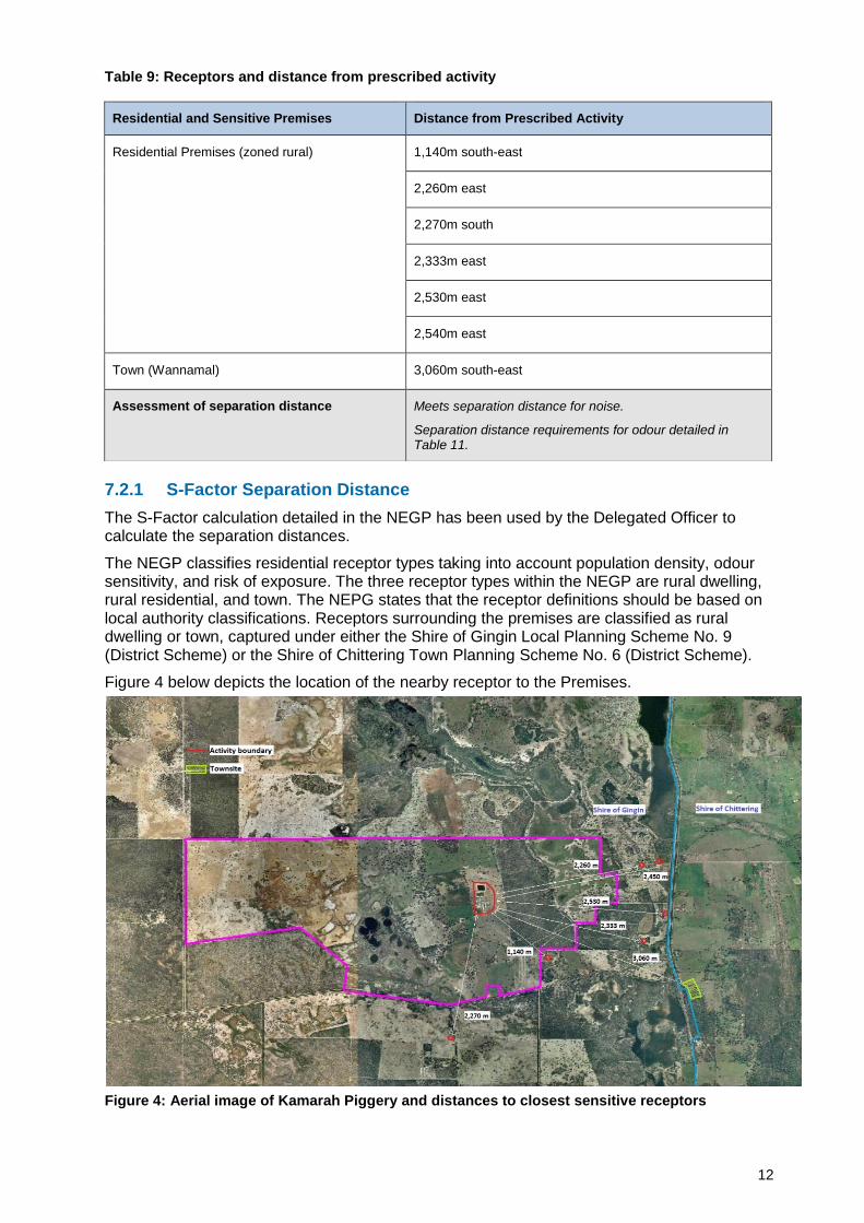
Table 9: Receptors and distance from prescribed activity
7.2.1 S-Factor Separation Distance
The S-Factor calculation detailed in the NEGP has been used by the Delegated Officer to calculate the separation distances.
The NEGP classifies residential receptor types taking into account population density, odour sensitivity, and risk of exposure. The three receptor types within the NEGP are rural dwelling, rural residential, and town. The NEPG states that the receptor definitions should be based on local authority classifications. Receptors surrounding the premises are classified as rural dwelling or town, captured under either the Shire of Gingin Local Planning Scheme No. 9 (District Scheme) or the Shire of Chittering Town Planning Scheme No. 6 (District Scheme).
Figure 4 below depicts the location of the nearby receptor to the Premises.
Figure 4: Aerial image of Kamarah Piggery and distances to closest sensitive receptors
Residential and Sensitive Premises Distance from Prescribed Activity
Assessment of separation distance Meets separation distance for noise.
Separation distance requirements for odour detailed in Table 11.
13
The Level 1 recommended distance for a rural dwelling has been calculated for the four closest residences. The recommended distances vary due to surface roughness and the type of terrain between the piggery and receptors. The Delegated Officer’s measurements have been taken from the activity boundary of the piggery relevant to the location of receptors or the Town boundary.
The Delegated Officer did not accept the S-Factor calculation provided by the Applicants as it did not calculate the entire piggery site as whole, but rather considered the site in two separated parts (conventional sheds and eco shelters considered separately).
The Delegated Officer’s determination of the separation distance using the S-Factor calculation is detailed below in Table 10 and a summary is provided in Table 11.
Table 10: S-Factor calculations
Receptor Type SPU S Factor S Factor Value Separation distance
Rural Dwelling 1 (RD) (1,140m south east)
25,384
S1R* 1.0
2,195m
S1T* 0.82
S2R 11.5
S2S** 0.88
S3 1
Rural Dwelling 2 (RD) (2,260m east)
25,384
S1R* 1.0
2,145m
S1T* 0.82
S2R 11.5
S2S*** 0.86
S3 1
Rural dwelling 3 (RD) (2,270m directly to the south)
25,384
S1R 1.0
2,495m
S1T* 0.82
S2R 11.5
S2S 1
S3 1
Rural Dwelling 4 (RD) (2,333 m east)
25,384
S1R* 1.0
2,120m
S1T* 0.82
S2R 11.5
S2S 0.85
S3 1
Rural residential 25,384
S1R* 1.0
3,254m
S1T* 0.82
S2R 15
S2S 1
S3 1
Town 25,384
S1R* 1.0
5,044m
S1T* 0.82
S2R 25
S2S****
0.93
S3 1
* The effluent treatment and removal factors have been weighted according to the number of SPU’s included in each shed system (conventional and eco shelters). The S1 factor for the piggery design is 0.82.
** The land between the piggery and the RD may be described as "level wooded country (S2s =0.85) associated with "limited ground cover/short grass (S2S = 1). A composite factor (as suggested by NEPG) of 0.88 would be an appropriate value for S2S.
14
*** The land between the piggery and the RD may be described as "level wooded country (S2s =0.85) associated with "limited ground cover/short grass (S2S = 1). A composite factor (as suggested by NEPG) of 0.86 would be an appropriate value for S2S.
****The land between the piggery and the town site boundary may be described as "level wooded country (S2s =0.85) associated with "limited ground cover/short grass (S2S = 1). A composite factor (as suggested by NEPG) of 0.93 would be an appropriate value for S2S.
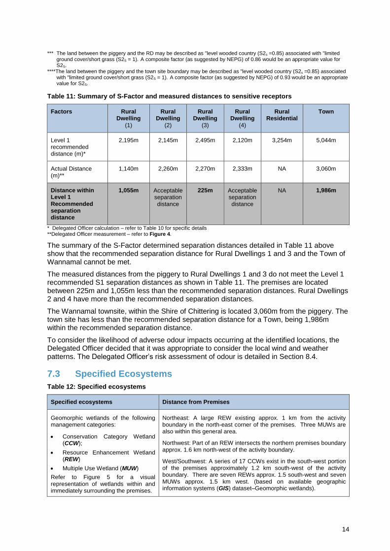
Table 11: Summary of S-Factor and measured distances to sensitive receptors
Factors Rural Dwelling
(1)
Rural Dwelling
(2)
Rural Dwelling
(3)
Rural Dwelling
(4)
Rural Residential
Town
Level 1 recommended distance (m)*
2,195m 2,145m 2,495m 2,120m 3,254m 5,044m
Actual Distance (m)**
1,140m 2,260m 2,270m 2,333m NA 3,060m
Distance within Level 1 Recommended separation distance
1,055m
Acceptable separation distance
225m
Acceptable separation distance
NA 1,986m
* Delegated Officer calculation – refer to Table 10 for specific details **Delegated Officer measurement – refer to Figure 4.
The summary of the S-Factor determined separation distances detailed in Table 11 above show that the recommended separation distance for Rural Dwellings 1 and 3 and the Town of Wannamal cannot be met.
The measured distances from the piggery to Rural Dwellings 1 and 3 do not meet the Level 1 recommended S1 separation distances as shown in Table 11. The premises are located between 225m and 1,055m less than the recommended separation distances. Rural Dwellings 2 and 4 have more than the recommended separation distances.
The Wannamal townsite, within the Shire of Chittering is located 3,060m from the piggery. The town site has less than the recommended separation distance for a Town, being 1,986m within the recommended separation distance.
To consider the likelihood of adverse odour impacts occurring at the identified locations, the Delegated Officer decided that it was appropriate to consider the local wind and weather patterns. The Delegated Officer’s risk assessment of odour is detailed in Section 8.4.
7.3 Specified Ecosystems
Table 12: Specified ecosystems
Specified ecosystems Distance from Premises
Geomorphic wetlands of the following management categories:
Conservation Category Wetland (CCW);
Resource Enhancement Wetland (REW)
Multiple Use Wetland (MUW)
Refer to Figure 5 for a visual representation of wetlands within and immediately surrounding the premises.
Northeast: A large REW existing approx. 1 km from the activity boundary in the north-east corner of the premises. Three MUWs are also within this general area.
Northwest: Part of an REW intersects the northern premises boundary approx. 1.6 km north-west of the activity boundary.
West/Southwest: A series of 17 CCWs exist in the south-west portion of the premises approximately 1.2 km south-west of the activity boundary. There are seven REWs approx. 1.5 south-west and seven MUWs approx. 1.5 km west. (based on available geographic information systems (GIS) dataset–Geomorphic wetlands).
15
Specified ecosystems Distance from Premises
RIWI Act: Proclaimed Surface Water Area – Gingin Brook Catchment Area
Does not intersect with the premises, however, it commences at the property boundary of the premises, approx. 1.6 km south of the activity boundary.
Public drinking water source area (PDWSA) Priority 1
3km and 7km north of the premises boundary (based on available GIS dataset–Threatened Ecological Sites Buffered).
TECs (priority) Number of TEC buffered sites located between approximately 500m and 10 km south of the premises boundary
Rare flora Number of threatened and priority flora located approximately between 2km and 4km from the eastern boundary of the premises. (based on available GIS dataset–Threatened and Priority Flora).
Other relevant ecosystem values Distance from Premises
Boonanarring Nature Reserve 2,381m south-west of the premises boundary
Lake Wannamal Nature Reserve 1,430m east of the premises boundary
Betts Nature Reserve 774m north east of the premises boundary
Lake Wannamal
The premises is located in the Swan-Avon catchment
2,730m northeast of the premises boundary
Brockman River
A major tributary of Brockman River runs through the premises, entering at the southern boundary. The tributary runs into the geomorphic wetlands onsite.
2,370m east of the premises boundary
Moore River 13.6km north of the premises boundary
16
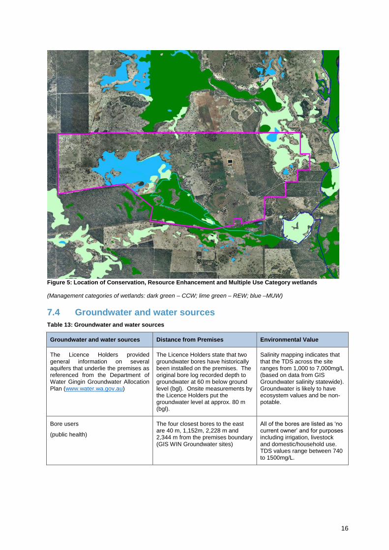
Figure 5: Location of Conservation, Resource Enhancement and Multiple Use Category wetlands
(Management categories of wetlands: dark green – CCW; lime green – REW; blue –MUW)
7.4 Groundwater and water sources
Table 13: Groundwater and water sources
Groundwater and water sources Distance from Premises Environmental Value
The Licence Holders provided general information on several aquifers that underlie the premises as referenced from the Department of Water Gingin Groundwater Allocation Plan (www.water.wa.gov.au)
The Licence Holders state that two groundwater bores have historically been installed on the premises. The original bore log recorded depth to groundwater at 60 m below ground level (bgl). Onsite measurements by the Licence Holders put the groundwater level at approx. 80 m (bgl).
Salinity mapping indicates that that the TDS across the site ranges from 1,000 to 7,000mg/L (based on data from GIS Groundwater salinity statewide). Groundwater is likely to have ecosystem values and be non-potable.
Bore users
(public health)
The four closest bores to the east are 40 m, 1,152m, 2,228 m and 2,344 m from the premises boundary (GIS WIN Groundwater sites)
All of the bores are listed as ‘no current owner’ and for purposes including irrigation, livestock and domestic/household use. TDS values range between 740 to 1500mg/L.
The Licence Holders stated the following in the Application:
“The Perth 1:250 000 Geology Map Sheet (GWSA, 1978) identified the site as containing colluvium, soil and undifferentiated sands over laterite of Coastal Plain with minor alleviated areas.”
DER’s GIS database provides the following general description of soils encountered in the localised area:
“Broad valleys and undulating interfluvial areas with some discontinuous breakaways and occasional mesas; lateritic materials mantle the area: chief soils are sandy acidic yellow mottled soils, containing much ironstone gravel in the A horizons, and forming a complex pattern with lateritic sandy gravels. Associated are leached sands underlain by lateritic gravels and mottled clays that occur at a progressively greater depth down slope”.
7.6 Meteorology
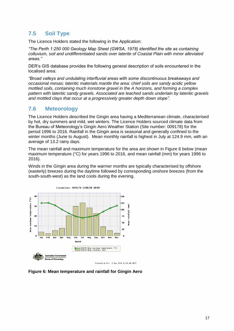
The Licence Holders described the Gingin area having a Mediterranean climate, characterised by hot, dry summers and mild, wet winters. The Licence Holders sourced climate data from the Bureau of Meteorology’s Gingin Aero Weather Station (Site number: 009178) for the period 1996 to 2016. Rainfall in the Gingin area is seasonal and generally confined to the winter months (June to August). Mean monthly rainfall is highest in July at 124.9 mm, with an average of 13.2 rainy days.
The mean rainfall and maximum temperature for the area are shown in Figure 6 below (mean maximum temperature (°C) for years 1996 to 2016, and mean rainfall (mm) for years 1996 to 2016).
Winds in the Gingin area during the warmer months are typically characterised by offshore (easterly) breezes during the daytime followed by corresponding onshore breezes (from the south-south-west) as the land cools during the evening.
Figure 6: Mean temperature and rainfall for Gingin Aero
It is important to note that these wind roses show historical wind speed and wind direction data for Wannamal weather station and should not be used to predict future data.
Identification of key potential emissions, pathways, receptors and impacts are set out in Table 14 and Table 15 below. Table 14 and Table 15 also identify which potential emissions and impacts will be progressed to a full risk assessment. Some potential emissions/impacts may not receive a full risk assessment if a potential receptor or pathway cannot be identified.
Table 14: Identification of key emissions during construction
Potential Emissions
Potential Receptors Potential Pathway
Potential Impacts Continued to detailed risk assessment?
Reasoning
So
urc
e (
se
e S
ectio
n
4.1
fo
r in
fra
str
uctu
re
refe
rences)
Construction and positioning
of infrastructure
Vehicle movements on unsealed access roads
Dust
Six residential premises receptors within approx. 2.5 km from activity boundary. Closest receptor is 1.14 km south-east.
Air / wind dispersion
Amenity and health impacts
No Sufficient separation distance
Construction of new buildings, plant and infrastructure
Noise Amenity impacts No Sufficient separation distance
Table 15 : Identification of key emissions during operation
Potential
Emissions Potential Receptors
Potential Pathway
Potential Impacts Continued to detailed risk assessment?
Reasoning
So
urc
e (
se
e S
ectio
n x f
or
infr
astr
uctu
re r
efe
ren
ce
s)
Accommodation of pigs and storage and
processing of waste materials
Existing and proposed conventional sheds and eco shelters
Odour
Six residential premises receptors within approx. 2.5 km from activity boundary. Closest receptor is 1.14 km south-east.
Wannamal town approx. 3 km south-east.
Air / wind dispersion
Amenity impacts
Yes See section 8.4
Noise
Six residential premises receptors within approx. 2.5 km from activity boundary. Closest receptor is 1.14 km south-east.
No Sufficient separation distance
20
Potential
Emissions Potential Receptors
Potential Pathway
Potential Impacts Continued to detailed risk assessment?
Reasoning
Contaminated wastewater surface runoff and seepage
Surface water / wetlands (Table 12)
Direct discharge and surface runoff
Terrestrial / wetland ecosystem impacts
Yes See section 8.5
Groundwater (60 – 80 m bgl)
Potential groundwater hydraulic link to wetlands (Table 12)
Direct discharge and infiltration through soil profile
Groundwater dependent ecosystems and wetland ecosystem impacts
No Sufficient separation distance
Collection, treatment and storage of waste materials
Existing and proposed anaerobic ponds and existing facultative pond
Odour
Six residential premises receptors within approx. 2.5 km from activity boundary. Closest receptor is 1.14 km south-east.
Wannamal town approx. 3 km south-east.
Air / wind dispersion
Amenity Yes See section 8.4
Wastewater discharge from ponds from overtopping, breach of containment, liner damage/faults.
Rupture of wastewater transfer pipelines.
Surface water / wetlands (Table 12)
Direct discharge and surface runoff
Terrestrial / wetland ecosystem impacts
Yes See section 8.5
Groundwater (60 – 80 m bgl)
Potential groundwater hydraulic link to wetlands (Table 12)
Direct discharge and infiltration through soil profile
Groundwater dependent ecosystems and wetland ecosystem impacts
Yes See section 8.6
Fan separator (screw press) (including use for desludging) and solid waste containment area
Odour
Six residential premises receptors within approx. 2.5 km from activity boundary. Closest receptor is 1.14 km south-east.
Wannamal town approx. 3 km south-east.
Air / wind dispersion
Amenity Yes See section 8.4
Wastewater discharges through breach of containment,
Surface water / wetlands(Table 12)
Direct discharge and surface runoff
Terrestrial / wetland ecosystem impacts
Yes See section 8.5
21
Potential
Emissions Potential Receptors
Potential Pathway
Potential Impacts Continued to detailed risk assessment?
Reasoning
runoff and seepage
Groundwater (60 – 80 m bgl)
Potential groundwater hydraulic link to wetlands (Table 12)
Direct discharge and infiltration through soil profile
Groundwater dependent ecosystems and wetland ecosystem impacts
No Sufficient separation distance
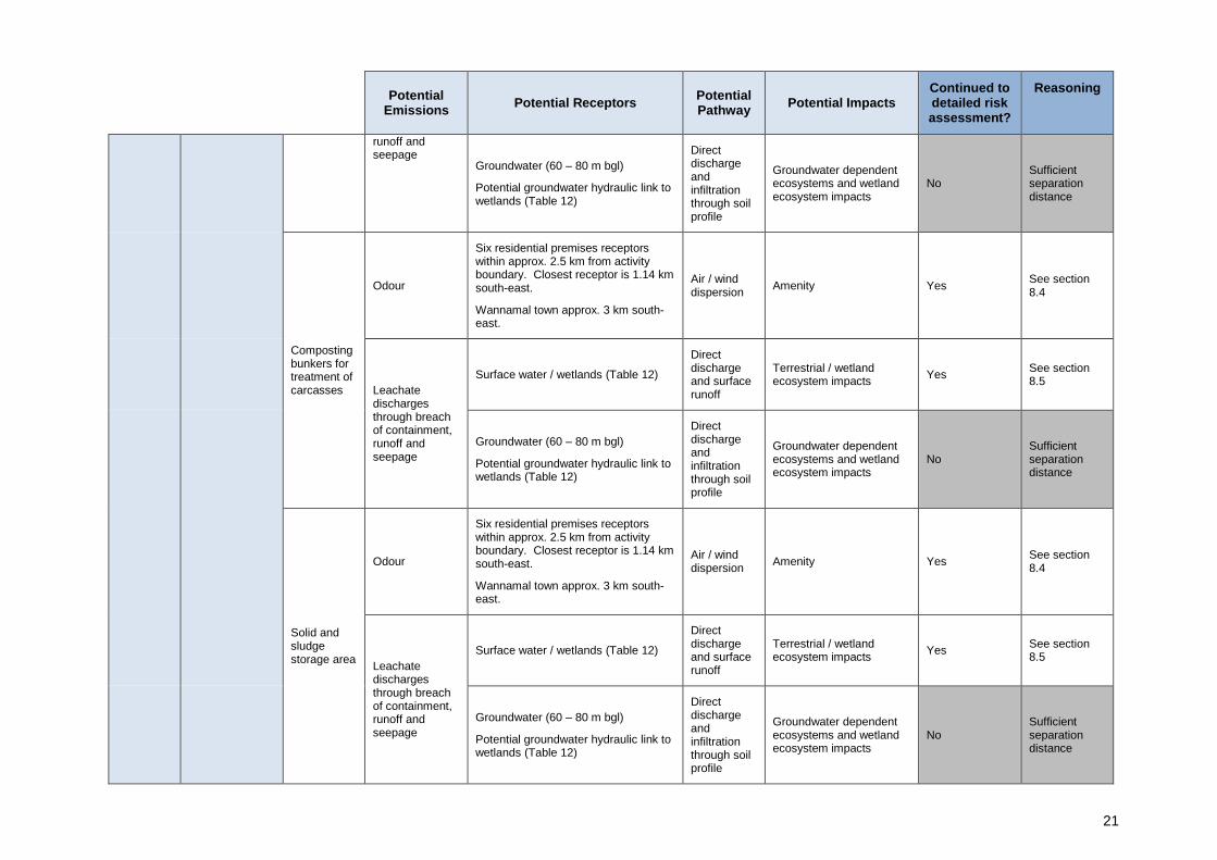
Composting bunkers for treatment of carcasses
Odour
Six residential premises receptors within approx. 2.5 km from activity boundary. Closest receptor is 1.14 km south-east.
Wannamal town approx. 3 km south-east.
Air / wind dispersion
Amenity Yes See section 8.4
Leachate discharges through breach of containment, runoff and seepage
Surface water / wetlands (Table 12)
Direct discharge and surface runoff
Terrestrial / wetland ecosystem impacts
Yes See section 8.5
Groundwater (60 – 80 m bgl)
Potential groundwater hydraulic link to wetlands (Table 12)
Direct discharge and infiltration through soil profile
Groundwater dependent ecosystems and wetland ecosystem impacts
No Sufficient separation distance
Solid and sludge storage area
Odour
Six residential premises receptors within approx. 2.5 km from activity boundary. Closest receptor is 1.14 km south-east.
Wannamal town approx. 3 km south-east.
Air / wind dispersion
Amenity Yes See section 8.4
Leachate discharges through breach of containment, runoff and seepage
Surface water / wetlands (Table 12)
Direct discharge and surface runoff
Terrestrial / wetland ecosystem impacts
Yes See section 8.5
Groundwater (60 – 80 m bgl)
Potential groundwater hydraulic link to wetlands (Table 12)
Direct discharge and infiltration through soil profile
Groundwater dependent ecosystems and wetland ecosystem impacts
No Sufficient separation distance
22
Potential
Emissions Potential Receptors
Potential Pathway
Potential Impacts Continued to detailed risk assessment?
Reasoning
Waste disposal
Mechanical spreading of eco shelters spent bedding to land
Odour
Six residential premises receptors within approx. 2.5 km from activity boundary. Closest receptor is 1.14 km south-east.
Wannamal town approx. 3 km south-east.
Air / wind dispersion
Amenity Yes See section 8.4
Dust
Six residential premises receptors within approx. 2.5 km from activity boundary. Closest receptor is 1.14 km south-east.
Amenity and health No Sufficient separation distance
Contaminated surface water runoff
Surface water / wetlands (Table 12)
Direct discharge and surface runoff
Terrestrial / wetland ecosystem impacts
Yes See section 8.5
Groundwater (60 – 80 m bgl)
Potential groundwater hydraulic link to wetlands (Table 12)
Direct discharge and infiltration through soil profile
Groundwater dependent ecosystems and wetland ecosystem impacts
No Sufficient separation distance
23
8.2 Risk Criteria
During the assessment, the risk criteria in Table 16 below will be applied to determine a risk rating set out in section 8.7.
Table 16 : Risk Criteria
Likelihood Consequence
Slight Minor Moderate Major Severe
Almost Certain Medium High High Extreme Extreme
Likely Medium Medium High High Extreme
Possible Low Medium Medium High Extreme
Unlikely Low Medium Medium Medium High
Rare Low Low Medium Medium High
Likelihood Consequence
The following criteria has been used to determine the likelihood of the risk / opportunity occurring.
The following criteria has been used to determine the consequences of a risk occurring:
Environment Public Health* and Amenity (such as air and water quality, noise, and odour)
Almost Certain
The risk event is expected to occur in most circumstances
Severe on-site impacts: catastrophic
off-site impacts local scale: high level or above
off-site impacts wider scale: mid level or above
Mid to long term or permanent impact to an area of high conservation value or special significance^
Specific Consequence Criteria (for environment) are significantly exceeded
Loss of life
Adverse health effects: high level or ongoing medical treatment
Specific Consequence Criteria (for public health) are significantly exceeded
Local scale impacts: permanent loss of amenity
Likely The risk event will probably occur in most circumstances
Major on-site impacts: high level
off-site impacts local scale: mid level
off-site impacts wider scale: low level
Short term impact to an area of high conservation value or special significance^
Specific Consequence Criteria (for environment) are exceeded
Adverse health effects: mid level or frequent medical treatment
Specific Consequence Criteria (for public health) are exceeded
Local scale impacts: high level impact to amenity
Possible The risk event could occur at some time
Moderate on-site impacts: mid level
off-site impacts local scale: low level
off-site impacts wider scale: minimal
Specific Consequence Criteria (for environment) are at risk of not being met
Adverse health effects: low level or occasional medical treatment
Specific Consequence Criteria (for public health) are at risk of not being met
Local scale impacts: mid level impact to amenity
Unlikely The risk event will probably not occur in most circumstances
Minor on-site impacts: low level
off-site impacts local scale: minimal
off-site impacts wider scale: not detectable
Specific Consequence Criteria (for environment) likely to be met
Specific Consequence Criteria (for public health) are likely to be met
Local scale impacts: low level impact to amenity
Rare The risk event may only occur in exceptional circumstances
Slight on-site impact: minimal
Specific Consequence Criteria (for environment) met
Local scale: minimal to amenity
Specific Consequence Criteria (for public health) met
^ Determination of areas of high conservation value or special significance should be informed by the Guidance Statement: Environmental Siting. * In applying public health criteria, DER may have regard to the Department of Health’s, Health Risk Assessment (Scoping) Guidelines “on-site” means within the prescribed premises boundary.
24
8.3 Risk Treatment
DER will treat risks in accordance with the Risk Treatment Matrix below:
Table 17: Risk Treatment
Rating of Risk Event
Acceptability Treatment
Extreme Unacceptable. Risk event will not be tolerated. DER may refuse application.
High Acceptable subject to multiple regulatory controls.
Risk event will be tolerated and may be subject to multiple regulatory controls. This may include both outcome-based and management conditions.
Medium Acceptable, generally subject to regulatory controls.
Risk event is tolerable and is likely to be subject to some regulatory controls. A preference for outcome-based conditions where practical and appropriate will be applied.
Low Acceptable, generally not controlled
Risk event is acceptable and will generally not be subject to regulatory controls.
8.4 Risk of Odour Impact Analysis
8.4.1 General Hazard Characterisation and Impact
Odour sources include pig accommodation (eco shelters and conventional sheds), the solids separator (including solids storage), carcass compost areas, and ponds. Specific activities such as desludging anaerobic ponds and application of spent bedding to land also generate odour. Odour generated from intensive piggeries has the potential to cause amenity impacts on receptors. Odour emissions are likely to be variable dependent on activities occurring on the premises, day/night cycles, and weather conditions. The site is situated in a rural agricultural area, and the nearest residential premises are isolated rural dwellings.
As mentioned in section 7.2, the separation distance from the proposed expanded piggery premises to two rural dwellings and the Wannamal townsite does not meet the recommended distance.
8.4.2 Criteria for assessment
The Delegated Officer considers that assessment of odours should be in accordance with the criteria and methods detailed in the NEPG.
8.4.3 Licence Holders Controls
The following are the Licence Holders’ proposed controls for odour management as summarised from the Application:
Table 18: Licence Holders controls for odour emissions
Control Description
Siting/location Activity boundary centrally located with separation to premises boundary.
Predominant winds are easterly and southwesterly that disperse odours away from the nearest sensitive receptor.
Infrastructure Conventional sheds to be constructed with underfloor pits for waste collection and flushing on a 1 to 4-week rotation using the pull-plug design system.
25
Control Description
Fan separator to reduce solids loading in wastewater streams from new conventional sheds and anaerobic pond desludging.
Pig mortality composting bunkers and separated solids and sludge stored in areas with three sides and a roof.
Procedures / Management
Regular pen cleaning/housekeeping.
Pig mortalities removed immediately from the shed or eco shelters, once noticed.
Pig mortalities covered with 200mm of sawdust or straw immediately after placement in the composting bunker.
No spreading of spent bedding on the portion of the property adjacent to the closest residence.
Management of pH in the new anaerobic pond in the 6.8 to 8.0 range to help bacteria establishment.
Direction of wastewater from existing anaerobic ponds to the new fan separator then back to the new anaerobic pond to help with optimal bacterial population establishment.
Separated solids and sludge removed off site.
Infrequent and short duration of desludging events during weather conditions with easterly winds.
Odour measurement at the boundary of the premises and closest residence during the operational phase to determine if additional management measures are required.
Complaints management.
8.4.4 Key Findings
8.4.5 Consequence
Based on consideration to the location/siting of the premises and general hazard characterisation, odour emissions could have a low-level impact to amenity with any impact expected to be for short periods to isolated rural residences or a small population. Therefore, the Delegated Officer considers the consequence to be Minor.
8.4.6 Likelihood of Consequence
As mentioned in section 5.3, the review of the compliance, complaint and incident history did not identify that the existing piggery caused unacceptable odour impacts on nearby sensitive land uses.
As mentioned in section 7.2.1 of this report, the Delegated Officer considered that the likelihood of adverse odours occurring could also be informed by consideration of the local
The Delegated Officer has reviewed the information regarding the odour impacts from the premises and has found:
1. The proposed expanded piggery has less than the recommended separation distances (NEGP Level 1) from two rural dwellings and Wannamal town site.
2. The existing piggery has not caused odour related complaints or compliance issues in the past.
26
meteorology. Winds in Wannamal are typically from the south, and this will reduce the likelihood of adverse impacts occurring at Rural Dwellings 1 and 3 and at the Town of Wannamal.
The Delegated Officer considered that while odour impacts may occur at some locations, the lack of complaints about the existing piggery and local meteorology reduce the likelihood of adverse impacts occurring from the proposed expanded piggery. The Delegated Officer also considered that the receptors are located at isolated rural dwellings in a rural area and that approximately 50 people reside in Wannamal. The closest rural dwelling to the piggery is currently not permanently occupied. Therefore, the Delegated Officer considered the likelihood of the consequence to be Unlikely.
If in the event that the piggery has an unreasonable impact on sensitive land uses, there are infrastructure and management related options available to reduce odours.
8.4.7 Overall rating
The Delegated Officer has compared the consequence and likelihood ratings described above through the Risk Matrix in Table 16 and determined that the overall rating for the risk of odour emissions on sensitive receptors during operation is Medium.
8.5 Risk of Discharges to Land Impact Analysis
8.5.1 General Hazard Characterisation and Impact
Discharges to land may occur through contaminated runoff from hardstand surfaces, infrastructure loss of containment, spills and overtopping. Sources of wastewater and leachate discharges to land are summarised in Table 19.
Table 19: Potential sources of wastewater and leachate discharges to land
Source Potential event
Pig accommodation (conventional sheds and eco shelters)
Contaminated surface runoff
Wastewater treatment ponds Overtopping
Breach of containment
Liner damage/faults
Pipeline rupture spills
Fan separator Contaminated surface runoff
Breach of containment
Solid sludge storage Contaminated surface runoff
Breach of containment
Application of spent bedding to land Contaminated surface runoff
The Licence Holders provided a water balance for the wastewater treatment system including the inputs used and outputs determined from the PigBal modelling. Assessment of this information and the findings are included in section 4.2.3.
The NEGP provides typical data for the composition of piggery effluent and sludge from conventional piggeries which are shown in Table 20 and Table 21. Wastes are typically rich in nutrients (nitrogen and phosphorus), pathogens, potassium, sulfur and trace elements (e.g. zinc, copper and manganese).
27
Table 20: Characteristics of piggery pond irrigation effluent (as sourced from Table 14.1 in the NEGP)
Table 21: Characteristics of in situ piggery pond sludge (as sourced from Table 14.2 in the NEGP)
Wastewater and leachate discharges to land into nearby terrestrial and wetland ecosystems would be expected to cause water quality impacts, may disrupt ecosystem processes and result in eutrophication. The premises does not have wastewater and leachate discharges to land under normal operating conditions, therefore, impacts would not be expected under normal circumstances. Wastewater and leachate discharges to land would be expected to occur as a result of an accident or malfunction of infrastructure and equipment or through
28
inadequate design.
The Licence Holders have existing eco shelters whereby spent bedding containing accumulated pig manure is applied to paddocks within the premises by mechanical spreader. The characteristics of this material are likely to be similar to the characteristics of wastewater and sludges. Land application of approximately 1,380 m3 of spent straw will occur every twelve weeks; totalling 5,980 m3 applied each year.
Spent bedding will be used to fertilise crops, with the uptake of nutrients by the crop. The application of spend bedding to land is further outlined in section 4.2.1 of this Decision report. There is potential for soil degradation/contamination and eutrophication of surface water bodies if runoff and leaching of nutrients/contaminants occur beyond the crop root zone.
8.5.2 Criteria for Assessment
Australian and New Zealand (ANZECC) Guidelines for Fresh and Marine Water Quality are considered appropriate assessment criteria to assess the potential impact on surface water quality.
8.5.3 Licence Holders controls
The Licence Holders’ controls for discharges to land in Table 22 are sourced from the Application. Table 22: Licence Holders controls for discharges to land
Site infrastructure Description
Proposed conventional sheds
Three new conventional sheds with floors constructed of concrete and partly slatted to allow effluent to collect beneath the floor in concrete pits. The drainage system will be pull-plug system.
Proposed eco shelters Concrete floor with bunded sides to contain bedding material.
Spent bedding managed as per existing eco shelters.
Proposed composting bunkers
Roof to prevent rainfall ingress and minimise leachate generation.
Pig mortalities are immediately covered with a minimum of 200mm of sawdust/straw on deposition.
Pig mortalities are placed within the composting bunkers upon becoming aware of the mortality.
Proposed anaerobic pond Capable of capturing rainfall associated with a 1 in 10 year ARI rainfall event of 72-hour duration without overtopping.
Stormwater directed away from the pond.
Proposed fan separator and collection bunker
Solid wastes from the fan separator are collected and contained within a bunker with a concrete floor, concrete sides and a roof.
Solid wastes including any leachate is contained within a bunded hardstand surface.
Accumulated solid wastes in the bunker are collected by a third party and removed from the Premises on an as needs basis.
Existing conventional sheds
All effluent is contained within hardstand surfaces of the sheds.
Effluent enters an open channel or drain and is flushed or hosed to direct it into the wastewater treatment system.
Existing eco shelters All effluent is contained within hardstand surfaces consisting of concrete floors layered with straw/sawdust and partial height concrete sides.
A high tensile fabric roof is fitted to minimise rainfall ingress.
24 new eco shelters will have concrete footings and floors with a high tensile fabric over a steel framework acting as a roof.
Spent bedding in eco shelters is cleaned out for application to land
29
Site infrastructure Description
at a rate of four eco shelters per fortnight.
A mechanical spreader is used to apply spent bedding to land on the Premises.
Spent bedding is applied at a rate not exceeding 15m3/ha.
Spent bedding is preferentially applied to crops prior to sowing or during active growth.
Spent bedding is applied to land evenly.
Spent bedding is not applied during rainfall.
Spent bedding is not applied to any portion of the Premises within 100m of a geomorphic wetland
Existing wastewater treatment ponds
All ponds are designed to capture rainfall from a 1 in 10 ARI rainfall event of 72-hour duration without overtopping.
All ponds maintain a minimum top of embankment freeboard of 500 mm.
Effluent from the facultative pond is reused through the proposed conventional sheds for flushing.
All pond inner and outer embankments are maintained free of emergent vegetation.
Stormwater runoff is directed away from all ponds.
All pond embankments are designed to prevent erosion as a result of stormwater runoff.
Anaerobic ponds are desludged on a 3.5-year rotational basis.
Ponds are visually inspection on a daily basis to ascertain freeboard.
Proposed and existing Effluent transfer pipelines
Effluent is transported in PVC pipes.
PVC pipes are visually inspected on a daily basis
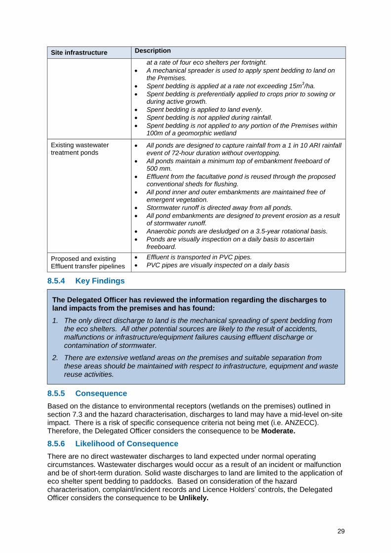
8.5.4 Key Findings
8.5.5 Consequence
Based on the distance to environmental receptors (wetlands on the premises) outlined in section 7.3 and the hazard characterisation, discharges to land may have a mid-level on-site impact. There is a risk of specific consequence criteria not being met (i.e. ANZECC). Therefore, the Delegated Officer considers the consequence to be Moderate.
8.5.6 Likelihood of Consequence
There are no direct wastewater discharges to land expected under normal operating circumstances. Wastewater discharges would occur as a result of an incident or malfunction and be of short-term duration. Solid waste discharges to land are limited to the application of eco shelter spent bedding to paddocks. Based on consideration of the hazard characterisation, complaint/incident records and Licence Holders’ controls, the Delegated Officer considers the consequence to be Unlikely.
The Delegated Officer has reviewed the information regarding the discharges to land impacts from the premises and has found:
1. The only direct discharge to land is the mechanical spreading of spent bedding from the eco shelters. All other potential sources are likely to the result of accidents, malfunctions or infrastructure/equipment failures causing effluent discharge or contamination of stormwater.
2. There are extensive wetland areas on the premises and suitable separation from these areas should be maintained with respect to infrastructure, equipment and waste reuse activities.
30
8.5.7 Overall rating
The Delegated Officer has compared the consequence and likelihood ratings described above through the Risk Matrix (Table 16) and determined that the overall rating for the risk of discharges to land on sensitive receptors during operation is Medium.
8.6 Risk of Wastewater Treatment Pond Seepage Analysis
8.6.1 General Hazard Characterisation and Impact
Seepage from ponds can occur through damage, malfunction or faults that occur during installation or the operational life of the liner. Seepage may result in transmission of stored effluent through the soil profile to groundwater. Seepage can occur at varying degrees depending on the nature of the damage, malfunction or fault over a long period of time. Contamination of groundwater has the potential to impact on groundwater dependent ecosystems and may impact on surface water resources (e.g. wetlands) where hydraulic links exist. Activities such as mechanical desludging of anaerobic ponds have the potential to damage liners and result in seepage. Depth to groundwater is between 60–80 m below ground level. Impacts to groundwater from seepage are not expected under normal operation conditions where a liner has been installed to an acceptable standard, tested and is protected from activities such as desludging.
8.6.2 Criteria for Assessment
Australian and New Zealand (ANZECC) Guidelines for Fresh and Marine Water Quality are considered appropriate assessment criteria to assess the potential impact on groundwater.
With reference to the installation and testing of liners using engineered soils, the Delegated Officer had regard to Water Quality Protection Note 27: Liners for containing pollutants, using engineered soils, Department of Water, 2013 (WQPN27) and the Wastewater Guidelines, Wastewater lagoon construction, Environmental Protection Authority South Australia, November 2014 (EPASA Lagoon Guidelines). These guidelines do not contain specifications which must be met but rather provide guidance on general design specification for the purposes of risk-based assessment of proposed design specifications.
8.6.3 Licence Holders controls
The Licence Holders controls for seepage from wastewater treatment ponds in Table 23 is sourced from the Application.
Table 23: Licence Holders controls for seepage from wastewater treatment ponds
Control Description
Siting/location Separation to sensitive receptors.
Depth to groundwater is between 60m to 80m below ground level
Engineering design
Existing ponds (two anaerobic and one facultative)
permeability <10-9
m/s with clay liner
Proposed anaerobic pond
Use of in situ clay to construct anaerobic pond liner
Clay at the base and sides of the pond will be compacted using a padfoot roller to a minimum thickness of 300mm.
Target maximum dry density of greater than 98% and resulting compacted in situ permeability of liner being <10
-9 m/s.
Testing and validation consistent with WQPN27
31
8.6.4 Key Findings
8.6.5 Consequence
Based on the hazard characterisation, depth to groundwater and the Licence Holders controls, the Delegated Officer has determined that the impact of seepage from ponds would be low-level on-site impact. Therefore, the Delegated Officer considers the consequence to be Minor.
8.6.6 Likelihood of Consequence
Based upon the Licence Holders controls, depth to groundwater and receptors, the Delegated Officer has determined that a minor consequence will probably not occur. Therefore, the Delegated Officer considers the consequence to be Unlikely.
8.6.7 Overall rating
The Delegated Officer has compared the consequence and likelihood ratings described above through the Risk Matrix (Table 16) and determined that the overall rating for the risk of seepage from ponds on sensitive receptors during operation is Medium.
The Delegated Officer has reviewed the information regarding the risk to groundwater and surface water impacts from the premises and has found:
1. The proposed method of pond desludging through the use of excavation equipment poses an inherent risk of damage to the clay lining of ponds.
32
8.7 Summary of Risk Assessment and Acceptability
The risk items identified in section 8.1 including the application of risk criteria and the acceptability with treatment are summarised in Table 24 below.
Table 24: Risk rating of emissions
Emission Pathway and Receptor
Proponent controls
Impact Risk Rating
Acceptability with treatment (conditions on instrument) Type Source
1. Fugitive odour (operation)
Pig effluent, separated solid wastes, carcasses, carcass composting, spent bedding application to land
Air, moving with direction of wind. Sensitive receptors located northeast, east, south-east and south.
Infrastructure, siting / location and management controls
Amenity Minor consequence
Possible
Medium risk
Acceptable subject to Licence Holders’ controls conditioned and regulatory conditions
2. Discharges to land (operation)
Mechanical application of spend bedding to land.
Infrastructure spills, leaks overtopping and contaminated runoff.
Direct discharge to land.
Terrestrial ecosystem / wetland ecosystem.
Management controls and siting / location
Ecosystem Surface water contamination
Moderate consequence
Unlikely
Medium risk
Acceptable subject to Licence Holders’ controls conditioned and regulatory controls
3. Wastewater pond seepage (operation)
Anaerobic ponds and facultative pond.
Direct discharge and infiltration through the soil profile.
Impacts on groundwater dependent ecosystems and wetland ecosystems.
Minor consequence
Unlikely
Medium risk
Acceptable subject to Licence Holders’ controls conditioned
33
9. Determined Regulatory Controls
9.1 Summary of Controls
Controls
9.2 Infrastructure Design or Construction Requirements
9.3 Requirements Regarding Operation of Infrastructure
9.4 Solid Waste Application to Land
9.5 Specified actions
Ris
k Ite
ms
(see s
ecti
on
8)
1. Fugitive odour • • •
2. Discharges to land
• • • •
3. Seepage from wastewater ponds • •
9.2 Infrastructure Design or Construction Requirements
9.2.1 Conventional sheds
Infrastructure Requirements (design and construction)
Conventional sheds (a) All sheds must have concrete pits underneath to enable pull-plug effluent management system.
(b) All sheds must comprise of concrete and partially slatted floors. (c) All sheds must enable the flushing of wastewater from the facultative pond
for flushing. (d) All underfloor pits must direct effluent to the anaerobic ponds via the fan
separator. (e) Stormwater runoff is to be directed away from all sheds. (f) All sheds must be separated by a distance of at least five times their height
to maximise ventilation.
Note: Requirements derived from the Licence Holders’ Application, except for the requirement for shed spacing.
Grounds: The proposal to house 25,384 SPU at the premises does not meet the recommended separation distance for the nearest rural dwellings as calculated in section 7.2. However, the Delegated Officer notes the lack of previous complaints history, the siting/location of the premises in a rural area, and the distance to the nearest rural dwelling is 1.14 km. The proposed conventional sheds will be required to have a separation of at least five times their height to maximise ventilation. This is consistent with the NEGP (Table 8.1) that provides this design consideration as adequate ventilation removes piggery gases, odour, controls air temperature and relative humidity, removes excess heat and moisture, dilutes and removes airborne disease organisms, and maintains oxygen levels.
9.2.2 Eco shelters
Infrastructure Requirements (design and construction)
Eco shelters All eco shelters must have a concrete floor with bunded sides to contain bedding material.
Note: Requirements derived from the Licence Holders’ Application.
34
9.2.3 Composting bunkers
Infrastructure Requirements (design and construction)
Composting bunkers (a) Bunkers must be 10 m long, 3 m wide and 2.4 m deep.
(b) Bunkers must have a roof to prevent the ingress of rainfall.
(c) Bunkers must have a hardstand concrete floor and three concrete sides with a front access gate.
(d) The hardstand concrete floor must prevent stormwater runoff entering the bunker.
Note: Requirements derived from the Licence Holders’ Application.
9.2.4 Fan separator and solids collection bunker
Infrastructure Requirements (design and construction)
Fan separator and solids collection bunker
The bunker must:
(a) be located underneath for the capture of fan separated solids;
(b) have a concrete floor and sides to contained solids;
(c) have a roof to prevent the ingress of rainfall.
Note: Requirements derived from the Licence Holders’ Application.
35
9.2.5 Anaerobic pond
Infrastructure Requirements (design and construction)
Anaerobic Pond (a) Designed and constructed to the dimensions specified in the Schedule 1: Anaerobic pond drawing.
(b) Embankments designed and constructed to prevent erosion as a result of stormwater runoff.
(c) Designed to allow access for desludging.
(d) A clay liner must meet the following specification:
(i) Minimum 150 mm subgrade preparation to provide a sound and stable base for liner construction. Subgrade preparation must include compaction until no rutting or pumping is observed.
(ii) Soils used for the liner must be free from plant roots and reactive, soluble and organic matter;
(iii) The liner material must meet the following criteria a. percentage fines with acceptability of:
i. more than 25 percent passing a 75-micron sieve; ii. more than 15 percent passing a 2-micron sieve, tested
using AS 1289 3.6.1; iii. liquid limit with acceptability of 30 to 70 percent tested
using AS 1289 3.1.2; iv. plasticity index with acceptability of more than 15, tested
using method AS 1289 3.3.1; and v. Emerson class number with acceptability of 5 to 6 tested
using AS 1289 3.8.1.
(e) The liner material must be homogeneous in nature and properties, with no sandy patches exceeding the liner specification or rocks retained on a 37.5mm sieve.
(f) The liner must be installed in at least two layers of equal thickness to ensure adequate compaction is achieved and be moisture-conditioned to achieve the maximum design soil density exceeding the 95 percent maximum (in place) dry density (MDD) determined using AS 1289 .5.2.1 and AS 12895.4.1.
(g) The minimum thickness of the compacted soil liner should be 300 mm with a tolerance of 5mm.
(h) The compacted liner must uniformly cover both the base and perimeter of the pond to achieve one integrated holding pond.
(i) The preparation and construction of the pond subgrade and liner must be supervised by a competent and experienced geotechnical professional.
(j) The liner must be certified in accordance with section 17 (Liner certification) of Water Quality Protection Note 27 – Liners for containing pollutants, using engineered soils, Western Australian Department of Water (August 2013).
(k) A minimum 300mm thickness layer of inert granular or gravel material is to cover the liner at the base of the pond to protect the liner during desludging. The cover must be applied in a manner that does not damage the lining and allows access for machines to desludge the lagoon without damage to the liner.
Note: Requirements are derived from the Licence Holders’ Application and requirements consistent with the guidance in WQPN27.
Grounds: The design and construction requirements for the anaerobic pond address the risk of discharge to land and the risk of seepage. The Application provided basic specifications for liner construction and included statements regarding testing and validation in accordance with WQPN27. Requirements specified above for liner construction and testing are consistent with WQPN27 which is an appropriate reference document for engineered soil liners given the hazard characteristics of effluent and the depth to groundwater.
Desludging presents an inherent risk of liner damage. Design requirements relating to desludging are consistent with the guidance in WQPN27.
36
9.2.6 Effluent transfer pipelines
Infrastructure Requirements (design and construction)
Effluent transfer pipelines
Effluent pipelines from the proposed conventional sheds to the anaerobic ponds via the fan separator are to be impermeable PVC piping.
Note: Delegated Officer requirement for the effluent transfer pipelines.
Grounds: The Application did not provide specifications for pipelines. Existing transfer pipelines at the premises are PVC, and continued use of this material for the proposed works is acceptable in consideration of the nature and characteristics of the effluent and the wastewater treatment system.
9.3 Requirements for Ongoing Operation of Infrastructure
9.3.1 Controls for odour
Infrastructure / equipment
Description Operation details
Controls for odour
Number of pigs held on the premises in the conventional shed, eco-shelters and in total.
The application has been assessed on holding 25,384 SPU in total with 7,429 SPU held in eco-shelter and 17,954 SPU held in conventional piggery sheds.
The number of pigs held should not exceed 25,384 SPU in total, 7,429 SPU in eco-shelters or 17,954 in conventional sheds at any time.
Conventional Sheds
Conventional sheds either have manual flush effluent drainage system or underfloor pits with pull – plug effluent management system design.
Manual flush effluent management system conventional sheds are cleaned at least on a daily basis.
Conventional sheds with underfloor pits are flushed on a 1 to 4-week rotation using the pull – plug effluent management system design.
Conventional sheds are swept and hosed to keep lanes, pens and handling areas clean.
Eco shelters Straw/sawdust is used as bedding material for the absorption of effluent.
Bedding material must be applied at a rate of 0.5 – 1 kg/pig/day and must be cleaned out and replaced prior to allowing each new batch of pigs into the shelters.
Shelters are stocked in accordance with Table 5, Appendix 3 of the Model Code of Practice for the Welfare of Animals - Pigs, Third Edition, CSIRO 2008.
Spent bedding is cleaned out for application to land at a rate of four eco shelters per fortnight.
Spent bedding is not applied to any portion of the Premises within 300 m of a rural dwelling not within the Premises and 25 m from the Premises boundary.
Composting bunkers
Pig mortalities are composted within the composting bunkers (or disposed off-site).
Pig mortalities are added to the compost bunkers upon becoming aware of the mortality.
Pig mortalities are placed in layers 0.5 m thick with alternating layers of sawdust/straw and eco shelters spent bedding.
Compost is not turned and groundwater bore water is added dependent on weather
37
Infrastructure / equipment
Description Operation details
conditions.
Bunkers are used on rotation for 3 to 6 months or until full and compost within a bunker is not removed for at least 3 months once full.
Final compost product is removed from the premises by a third party.
Burial of deceased animals is to cease on completion of the works
Fan separator Effluent from all conventional sheds and sludge removed from anaerobic ponds is treated by the fan separator to reduce the solids loading in waste streams.
Sludge treated by the solids separator is removed from the Premises by a third party.
The solids separator shall remove at least 25% of the total solids.
The solids separator must be operational for more than 95% of the time.
The solids separator must not be out of service for more than 3 consecutive days in any period of outage.
Note: Requirements are derived from the Licence Holders’ Application. Eco shelter stock rate requirements and conventional shed housekeeping requirements are additional regulatory controls.
Grounds: The proposal to house 25,384 SPU at the premises does not meet the recommended separation distance for the nearest rural dwellings as calculated in section 7.2. However, the Delegated Officer notes the lack of previous complaints history, the siting/location of the premises in a rural area and the distance to the nearest rural dwelling is 1.14 km. The Licence Holders will be required to manage eco shelter stocking rates. Section 8.2 of NEGP outlines that stocking rates in eco shelters need careful management to control odour generation. The NEGP refers to Appendix 3 of the Model Code of Practice for the Welfare of Animals: Pigs, CSIRO 2008 for recommended minimum space allowances for adult pigs and growing pigs, i.e. weaners, growers and finishers in eco shelters. Section 8.2 of NEGP also provides for bedding top-ups at a rate of 0.5 – 1 kg/pig/day to maintain dry, low odour conditions within the shelters. Table 8.1 of NEGP outlines that the dustier a piggery is, the more odorous it will be. Section 8.1 of NEGP states that “conventional sheds need regular sweeping and hosing to keep lanes, pens and handling areas clean.”
The application has been assessed and granted on the basis that a solids separator is used to reduce the total solids and volatile solids loading on the anaerobic pond, which will reduce odours. If the solids separator is not operational, there is a risk that the anaerobic pond may be overloaded and cause a significant odour event.
38
9.3.2 Controls to minimise discharges to land
Site infrastructure / equipment
Description
Conventional sheds
All effluent is contained within hardstand surfaces of the sheds.
Effluent from existing conventional sheds enters an open channel or drain and is flushed or hosed to direct it into the wastewater treatment system.
Effluent from the proposed conventional sheds falls through partly slatted concrete floors into contained concrete pits and is directed to the wastewater treatment system using a pull – plug effluent management system design. Water from the facultative pond is reused for flushing the pits
Eco shelters All effluent is contained within hardstand surfaces consisting of concrete floors layered with straw/sawdust and partial height concrete sides.
A high tensile fabric roof is fitted to minimise rainfall ingress.
Wastewater treatment ponds
At least one anaerobic pond is online at any given time while two anaerobic ponds are offline in stages of desludging and sludge drying.
All ponds are designed to capture rainfall from a 1 in 10 ARI rainfall event of 72-hour duration without overtopping.
All ponds maintain a minimum top of embankment freeboard of 500 mm.
Reuse of treated effluent from the facultative pond occurs as flushing water in pull-plug conventional sheds once the facultative pond reaches a top of embankment freeboard of 1 m.
All pond inner and outer embankments are free of emergent vegetation.
Stormwater runoff is directed away from all ponds.
All pond embankments are designed to prevent erosion as a result of stormwater runoff.
Ponds are visually inspection on a daily basis to ascertain freeboard.
Effluent transfer pipelines
Effluent is transported in PVC pipes.
PVC pipes are visually inspected on a daily basis
Composting bunkers
Two compost bunkers with a concrete floor with three concrete sides and a front access gate for the purpose of composting pig mortalities.
Any leachate generated remains contained within the bunkers.
Stormwater runoff is directed away from the bunkers.
Fan separator and solids collection bunker
Solid wastes from the fan separator are collected and contained within a bunker with a concrete floor, concrete sides and a roof.
Solid wastes including any leachate is contained within a bunded hardstand surface.
Accumulated solid wastes in the bunker are collected by a third party and removed from the Premises on an as needs basis.
Note: Requirements are derived from Licence Holders’ controls.
39
9.3.3 Controls to minimise seepage
Site infrastructure / equipment
Description
Wastewater treatment ponds
All ponds are clay lined with engineered soils to achieve a permeability of <10-9
m/s.
A minimum 300 mm thickness layer of inert granular or gravel material is covering the liner at the base of the anaerobic ponds at the completion of desludging and prior to operational use.
Desludging of anaerobic ponds does not breach the pond embankment or lining or result in any effluent runoff.
Note: Requirement for permeability is derived from Licence Holders’ controls. Desludging requirements are Delegated Officer derived requirements.
Grounds: Desludging requirements are risk-based consistent with the risk assessment outcomes of section 8.6 and guidance within WQPN27 relating to the protection of engineered soil liners from mechanical activities.
9.4 Solid Waste Application to Land
9.4.1 Eco shelter spent bedding
Infrastructure Waste type Requirements / operation details
Eco shelters Spent bedding Spent bedding in eco shelters is cleaned out for application to land at a rate of four eco shelters per fortnight.
Spent bedding is applied to land within the green shaded area of the Spent bedding application to land map.
A mechanical spreader is used to apply spent bedding to land on the Premises.
Spent bedding is applied at a rate not exceeding 15m3/ha.
Spent bedding is preferentially applied to crops prior to sowing or during active growth.
Spent bedding is applied to land evenly.
Spent bedding is not applied during rainfall.
Spent bedding is not applied to any portion of the Premises within 100m of a geomorphic wetland as depicted in the Geomorphic wetlands map.
Spent bedding is not applied to any portion of the Premises within: a. 300m of a rural dwelling not within the Premises; and b. 25m from the Premises boundary.
Note: Requirements are derived from the Licence Holders controls in section 8.5.3. Specific values for separation to dwelling and environmental receptors are additional regulatory controls. The spent bedding application to land map will be sourced from Figure 5 of the WNMP.
Grounds: Table 6.1 of NEGP provides recommended separation distances for waste reuse areas from watercourses. The recommended distance for “spent bedding that is spread immediately (i.e. not stockpiles / composted) and remains on the soil surface for more than 24 hours” is 100m. A separation to wetlands on the premises reduces the likelihood of environmental impacts.
Table A.10 in Appendix A of NEGP provides recommended separation distances surrounding by-product reuse areas. The recommended distances for “spent bedding that is spread immediately (i.e. is not stockpiled / composted) and remains on the soil surface for more than 24 hours (i.e. is not immediately ploughed in) are 300 m for a rural dwelling and 25 m from the
40
property boundary. These values are reasonable in the context of the hazard characterisation and siting context. A separation to dwellings reduces the likelihood of odour amenity and fugitive dust impacts on receptors.
9.5 Specified Actions
The Licence Holders must desludge all three anaerobic ponds on a three-year desludging interval where one anaerobic pond is desludged per year.
Note: Additional regulatory controls.
Grounds: The Licence Holders have two existing anaerobic ponds and propose to construct a third. They propose to have one anaerobic pond online receiving effluent with two anaerobic ponds offline in stages of desludging. However, PigBal modelling in the Application assumes the full anaerobic pond capacity is in one anaerobic pond and was based on a five-year desludging interval. Information available suggests that an anaerobic pond would need to be desludged approximately every 1.6 years or potentially every year in actuality to maximise the drying summer months for sludge drying. The Delegated Officer has conservatively specified the desludging interval in the absence of additional information or proposals from the Licence Holders.
10. Setting Conditions
10.1 Construction Phase
The conditions in the Amendment Notice have been determined in accordance with DER’s Guidance Statement on Setting Conditions.
Condition Ref Grounds
Location of Works Condition 6.1.1
This condition is valid, risk-based and consistent with the EP Act (see section 8 of this decision report).
Infrastructure Design and Construction Requirements Conditions 6.2.1 – 6.2.5
These conditions are valid, risk-based and contain appropriate controls (see section 8 of this decision report).
DER notes that it may review the appropriateness and adequacy of controls at any time and that following a review, DER may initiate amendments to the licence under the EP Act.
10.2 Post-Construction Phase
The Amendment Notice authorises works associated with the Application. At the completion of proposed works and subject to the Licence Holders fulfilling requirements of the Amendment Notice, a Revised Licence may be issued to give effect to the controls specified in sections 9.3, 9.4 and 9.5.
41
11. Licence Holders Comments on Risk Assessment
The Licence Holders was provided with the draft decision report and draft Amendment Notice on 12 January 2017. The Licence Holders’ comments and the Delegated Officer’s consideration are contained in Appendix 2.
12. Conclusion
This assessment of the risks of activities on the premises has been undertaken with due consideration of a number of factors, including the documents and policies specified in this decision report (summarised in Appendix 1). This assessment also considers the Application from the Licence Holders relating to a proposed expansion.
Based on this assessment, it has been determined that the Amendment Notice will be granted subject to conditions commensurate with the determined controls and necessary for administration and reporting requirements.
Jonathan Bailes A/Senior Manager – Industry Regulation An officer delegated under section 20 of the Environmental Protection Act 1986
42
Appendix 1: Key Documents
Document Title Availability
1 Licence L5008/1991/13 http://www.der.wa.gov.au
2 Environmental Protection Act 1986
Environmental Protection Regulations 1987
Environmental Protection (Noise) Regulations
1997
www.slp.wa.gov.au
3 Licence Amendment Application, Aurora
Environmental, 15 July 2016
DER records
4 Water quality protection note 27, Liners for
containing pollutants, using engineered soils,
Department of Water, August 2013
Gingin Groundwater Allocation Plan
http://www.water.wa.gov.au
5 National Environmental Guidelines for Piggeries,
Second Edition (Revised) 2010, Australian Pork
Limited
www.australianpork.com.au
6 Australian and New Zealand (ANZECC) Guidelines
for Fresh and Marine Water Quality
www.environment.gov.au
7 Compliance Inspections – 03/06/2011 and 26/03/2016 DER records
Appendix 2: Summary of Licence Holders Comments on Risk Assessment and Draft Conditions
Licensee comment (as summarised by the Delegated Officer)
Delegated Officer considerations
Amendment Notice
Higher resolution drawings of the fan separator and collection bunker were provided as requested by the Delegated Officer.
Drawings in Schedule 3 of the Amendment Notice replaced with higher resolution drawings provided by the Licence Holders.
Edits suggested for clarity.
Table 6.2.1 – Column 2:
(c) All sheds must be designed to enable the use of wastewater from the facultative pond for flushing enable the use flushing of wastewater from the facultative pond for flushing.
(e) Stormwater runoff, including from roofs, is to be directed aware away from sheds.
Table 6.2.1 updated consistent with wording and corrections suggested by the Licence Holders.
Decision Report
Purpose and scope:
Reference to 23 eco shelters should be 24 ecoshelters.
Corrected to 24 eco shelters which aligns with row 3 in Table 4.
Table 4:
Fan (screw press) separator with a concrete bunker/solids collection area under the screw press to capture separated solids from the underfloor pits.
Correct reference to Appendix 4: Map of new anaerobic pond design to Appendix 3.
Agreed. Row 2 updated to reflect Licence Holders’ suggested wording, noting that solids may also relate to pond desludging.
Corrected to reference Appendix 3.
Section 4.2.1:
Maps of ecoshelters spent bedding application to land and application nutrient balance provided through a Waste and Nutrient Management Plan prepared for clearance of planning conditions.
Noted.
Section 5.1:
Copy of planning approval provided.
Noted. Section 5.1 of the Decision Report updated.
Figure 3:
Arial Aerial image of the closest residential premises to Kamarah Piggery.
Figure 3 caption corrected.
44
Licensee comment (as summarised by the Delegated Officer)
Delegated Officer considerations
Table 10:
Table Note - The S1 factor for the piggery design is 0.81 0.82.
Table 10 table note corrected.
Section 8.5.3 (Table 23) and 9.3.2:
Visual pond and pipe inspections confirmed as daily.
Noted and updated in the Decision Report.
Section 9.3.1:
Manual flushing of existing conventional sheds confirmed as daily.