ALL OTHER TERMS AND CONDITIONS REMAIN UNCHANGED. BIDDERS MUST ACKNOWLEDGE RECEIPT OF THIS AMENDMENT WITH THEIR BID PROPOSAL. July 26, 2021 AMENDMENT SIX (6) RFP-017-C-2021(P) – Design-Build Services for Arthur Richards PK-8 New Build, St. Croix, U.S. Virgin Islands INSERT QUESTIONS AND ANSWERS Q1 Can you please confirm if a geotechnical report for the site was completed? If so, may you please provide this report. A1 A geotechnical report was completed for the site. Please see attached. The selected firm/team will be responsible to conduct and rely on its own investigation. Q2 May the VIDE please provide a survey plan with contours lines and spot elevations of the existing site. A2 Please see attached for the survey documents for the Evelyn M. Williams/Arthur A. Richards site. A CAD file is also available upon request and will be sent via email to interested bidders. Please send requests to [email protected]. Q3 May the VIDE please confirm the location and provide the site address for the new Arthur Richards PK-8. A3 The new Arthur A. Richards PreK-8 School will be located on the site of the existing Evelyn M. Williams School. It is Plot No. 13-A Estate Mt. Pleasant, Prince Quarter, St. Croix, USVI. Q4 May you also confirm how many buildings of the proposed Arthur Richards PK-8 will be used as a hurricane shelter.
Transcript
ALL OTHER TERMS AND CONDITIONS REMAIN UNCHANGED.
BIDDERS MUST ACKNOWLEDGE RECEIPT OF THIS AMENDMENT WITH THEIR BID PROPOSAL.
July 26, 2021
AMENDMENT SIX (6) RFP-017-C-2021(P) – Design-Build Services for Arthur Richards PK-8 New Build, St. Croix, U.S. Virgin Islands
INSERT QUESTIONS AND ANSWERS Q1 Can you please confirm if a geotechnical report for the site was
completed? If so, may you please provide this report. A1 A geotechnical report was completed for the site. Please see attached.
The selected firm/team will be responsible to conduct and rely on its own investigation.
Q2 May the VIDE please provide a survey plan with contours lines and
spot elevations of the existing site. A2 Please see attached for the survey documents for the Evelyn M.
Williams/Arthur A. Richards site. A CAD file is also available upon request and will be sent via email to interested bidders. Please send requests to [email protected].
Q3 May the VIDE please confirm the location and provide the site
address for the new Arthur Richards PK-8. A3 The new Arthur A. Richards PreK-8 School will be located on the site
of the existing Evelyn M. Williams School. It is Plot No. 13-A Estate Mt. Pleasant, Prince Quarter, St. Croix, USVI.
Q4 May you also confirm how many buildings of the proposed Arthur
Richards PK-8 will be used as a hurricane shelter.
Amendment Six (6) RFP-017-C-2021(P)—Design-Build Services for Arthur Richards PK-8 New Build, St. Croix, U.S. Virgin Islands Page 2 of 2
ALL OTHER TERMS AND CONDITIONS REMAIN UNCHANGED.
BIDDERS MUST ACKNOWLEDGE RECEIPT OF THIS AMENDMENT WITH THEIR BID PROPOSAL.
A4 One building on site will be used as a hurricane shelter—the Gymnasium building is the designated FEMA Shelter for the campus. Please note, the attached Utility building, designed to support the Gymnasium in the event of an emergency, must meet the same shelter safety requirements as the Gymnasium.
Q5 May you please provide desired start date for the new Arthur Richards
PK-8. A5 The desired start date for the design-build contract is November 1,
2021, subject to funding availability (FEMA funds). Q6 On the Mandatory List of Required Documents provided, which
documents, if any, are required at the time of proposal submission? A6 Please refer to Section K of the RFP for all documents that are
required during the time of submission. Q7 When is the anticipated date for the Notice of Award? A7 A Notice of Award will be issued to a selected firm once the
evaluation process is completed. Q8 When is the anticipated date for the Notice to Proceed? A8 A Notice to Proceed will be issued to the selected firm upon execution
of the contract. Q9 Per the language of the narrative in Attachment A (on page 1), a Net
Zero school is referenced. Will Net Zero be required for the Arthur Richards PK-8 School?
A9 The Arthur A. Richards campus, in exception for the gymnasium, is
designed to be net zero ready. The gymnasium, as the shelter, will be net zero-off the grid. Interior partitions have been designed to support conditioning requirements for a net zero ready design.
P O B o x 3 6 3 1 1 6 , S a n J u a n , P R 0 0 9 3 6 - 3 1 1 6
( 7 8 7 ) 7 6 1 - 2 5 7 0 ( 7 8 7 ) 7 4 8 - 6 9 7 0 w w w . j a c a s i e r r a . c o m
PRELIMINARY GEOTECHNICAL REPORT
Date: February 9, 2021
Job no.: 8176
Client: Mr. Lloyd F. Ramsey, DLR Group
Project: VIDE Arthur Richards School (Old Evelyn Williams School), St. Croix,
USVI
Coordinates: 17°42’29” N, 64°48’52” W
1.0 INTRODUCTION:
The present preliminary report covers the results of the geotechnical exploration
performed for the above referenced project. This project is part of the Virgin Islands
Department of Education (VIDE) educational facility master plan, which for this site consists of
a new construction project at the existing school facilities. Figure 1 in Appendix A presents a
satellite image showing the site location.
Jaca & Sierra Engineering, PSC was contracted by DLR Group to conduct site
investigations and prepare preliminary geotechnical recommendations for the project. The
exploration program was directed to obtain subsurface soil information to be utilized in our
engineering evaluation and in the formulation of pertinent recommendations for the intended
structure foundation system. This report has been prepared exclusively for design purposes for
this particular project.
2.0 FIELD AND LABORATORY WORK:
The field exploration consisted of drilling a total of nine (9) test borings, six (6) around
existing structures and the other three (3) along parking areas. Borings were drilled to depths
of 10 and 30 feet Beneath Existing Ground Surface (BEGS). Refer to the boring location satellite
image in Appendix A Figure 1.
Page 2 of 10
VIDE Arthur Richards School (Old Evelyn Williams School),
St. Croix, USVI – Job no. 8176
February 9, 2021
P O B o x 3 6 3 1 1 6 , S a n J u a n , P R 0 0 9 3 6 - 3 1 1 6
( 7 8 7 ) 7 6 1 - 2 5 7 0 ( 7 8 7 ) 7 4 8 - 6 9 7 0 w w w . j a c a s i e r r a . c o m
Subsurface drilling was executed by means of the power auger method as per ASTM
D1452 using a CME-55 trailer-mounted drill rig to drive a 2.25-inch Internal Diameter (ID)
helical hollow-stem auger into the ground. In-situ testing and soil sampling were achieved by
means of the Standard Penetration Test (SPT) using automatic hammer and split-spoon sampler
method according to ASTM D1586. The soil samples were secured in jars and transported to
our laboratory for visual-manual description (ASTM D2488) and moisture content
determination (ASTM D2216). Unconfined compressive strength (ASTM D2166, spring test)
and soil classification (ASTM D6913 for sieve analysis and ASTM D4318 for Atterberg limits)
tests were performed in selected samples.
The field and laboratory information were gathered to prepare boring logs, which reveal
the stratigraphy and soil properties at the locations of the borings. Boring logs and soil
classification tests results are included in Appendices B and C, respectively.
3.0 SUBSOIL GENERALIZED CONDITIONS:
3.1 Site Geology:
According to the geologic map of the St. Croix island, the explored area falls within a
geologic zone that corresponds to Kingshill Marl (Mkh). Figure 2 in Appendix A shows a portion
of the geologic map and the approximate site location.
3.2 Soil Stratigraphy:
The stratigraphy at the locations of the borings is characterized by an occurring upper 2
to 9 feet thick layer of man-made fill material underlain by native soils from the aforementioned
marl formation extending to the end of boreholes at 10 and 30 feet depth BEGS. Each stratum is
described as follows:
• Stratum no. 1 – Man-Made Fill (borings no. 1 to 3, 5, 6 and 8)
The upper man-made fill material is composed mostly of silty clay and sandy
clay with variable amounts of gravel. SPT-N values recorded are varying from 6
Page 3 of 10
VIDE Arthur Richards School (Old Evelyn Williams School),
St. Croix, USVI – Job no. 8176
February 9, 2021
P O B o x 3 6 3 1 1 6 , S a n J u a n , P R 0 0 9 3 6 - 3 1 1 6
( 7 8 7 ) 7 6 1 - 2 5 7 0 ( 7 8 7 ) 7 4 8 - 6 9 7 0 w w w . j a c a s i e r r a . c o m
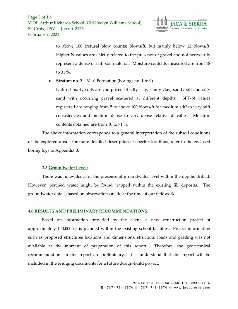
to above 100 (refusal blow counts) blows/ft, but mainly below 12 blows/ft.
Higher N values are chiefly related to the presence of gravel and not necessarily
represent a dense or stiff soil material. Moisture contents measured are from 18
Natural marly soils are comprised of silty clay, sandy clay, sandy silt and silty
sand with occurring gravel scattered at different depths. SPT-N values
registered are ranging from 5 to above 100 blows/ft for medium stiff to very stiff
consistencies and medium dense to very dense relative densities. Moisture
contents obtained are from 10 to 71 %.
The above information corresponds to a general interpretation of the subsoil conditions
of the explored area. For more detailed description at specific locations, refer to the enclosed
boring logs in Appendix B.
3.3 Groundwater Level:
There was no evidence of the presence of groundwater level within the depths drilled.
However, perched water might be found trapped within the existing fill deposits. The
groundwater data is based on observations made at the time of our fieldwork.
4.0 RESULTS AND PRELIMINARY RECOMMENDATIONS:
Based on information provided by the client, a new construction project of
approximately 140,000 ft2 is planned within the existing school facilities. Project information
such as proposed structures locations and dimensions, structural loads and grading was not
available at the moment of preparation of this report. Therefore, the geotechnical
recommendations in this report are preliminary. It is understood that this report will be
included in the bridging documents for a future design-build project.
Page 4 of 10
VIDE Arthur Richards School (Old Evelyn Williams School),
St. Croix, USVI – Job no. 8176
February 9, 2021
P O B o x 3 6 3 1 1 6 , S a n J u a n , P R 0 0 9 3 6 - 3 1 1 6
( 7 8 7 ) 7 6 1 - 2 5 7 0 ( 7 8 7 ) 7 4 8 - 6 9 7 0 w w w . j a c a s i e r r a . c o m
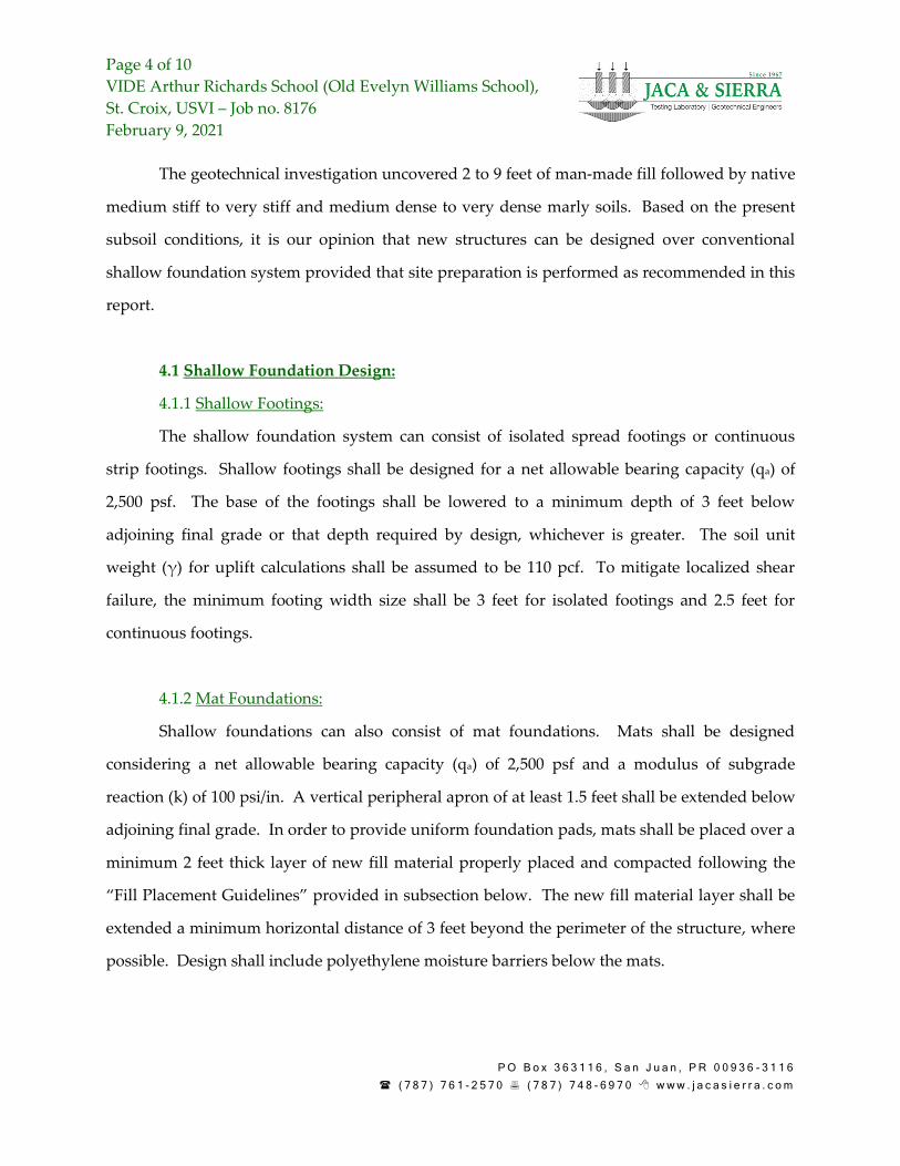
The geotechnical investigation uncovered 2 to 9 feet of man-made fill followed by native
medium stiff to very stiff and medium dense to very dense marly soils. Based on the present
subsoil conditions, it is our opinion that new structures can be designed over conventional
shallow foundation system provided that site preparation is performed as recommended in this
report.
4.1 Shallow Foundation Design:
4.1.1 Shallow Footings:
The shallow foundation system can consist of isolated spread footings or continuous
strip footings. Shallow footings shall be designed for a net allowable bearing capacity (qa) of
2,500 psf. The base of the footings shall be lowered to a minimum depth of 3 feet below
adjoining final grade or that depth required by design, whichever is greater. The soil unit
weight (γ) for uplift calculations shall be assumed to be 110 pcf. To mitigate localized shear
failure, the minimum footing width size shall be 3 feet for isolated footings and 2.5 feet for
continuous footings.
4.1.2 Mat Foundations:
Shallow foundations can also consist of mat foundations. Mats shall be designed
considering a net allowable bearing capacity (qa) of 2,500 psf and a modulus of subgrade
reaction (k) of 100 psi/in. A vertical peripheral apron of at least 1.5 feet shall be extended below
adjoining final grade. In order to provide uniform foundation pads, mats shall be placed over a
minimum 2 feet thick layer of new fill material properly placed and compacted following the
“Fill Placement Guidelines” provided in subsection below. The new fill material layer shall be
extended a minimum horizontal distance of 3 feet beyond the perimeter of the structure, where
possible. Design shall include polyethylene moisture barriers below the mats.
Page 5 of 10
VIDE Arthur Richards School (Old Evelyn Williams School),
St. Croix, USVI – Job no. 8176
February 9, 2021
P O B o x 3 6 3 1 1 6 , S a n J u a n , P R 0 0 9 3 6 - 3 1 1 6
( 7 8 7 ) 7 6 1 - 2 5 7 0 ( 7 8 7 ) 7 4 8 - 6 9 7 0 w w w . j a c a s i e r r a . c o m
4.2 Seismic Site Classification:
Based on our evaluation of the test borings completed and our knowledge of the site
geological conditions, it is our opinion that the seismic site classification as per ASCE 7-16 is Site
Class D, which corresponds to a stiff soil profile. The design spectral acceleration parameter at
short period (SDS) is 0.653 g. For the design spectral acceleration parameter at 1 second period
(SD1), note that ASCE 7-16 Section 11.4.8 states that structures on Site Classes D and E with
mapped maximum considered earthquake spectral response acceleration parameter at 1 second
period (S1) greater than or equal to 0.200 g will require a site-specific ground motion hazard
analysis. The parameter S1 at the project site is 0.307 g. Exceptions to this requirement could
apply and shall be evaluated by the structural design engineer. The Peak Ground Acceleration
(PGA) at the project site is 0.358 g.
4.3 Earth Retaining Structures:
Any retaining wall system required within the project site area may consist of
Mechanically Stabilized Earth (MSE) walls, concrete cantilever walls or any other types of
gravity walls. The lateral earth pressure parameters will depend on many factors including the
type of soil used as backfill and the equipment used to perform the compaction procedures.
Our suggested soil parameters for earth pressure calculations and design assuming new A-2-4
soil material (AASHTO) as backfill are the following:
• Cohesion (c) = 0 psf,
• Angle of internal friction (φ) = 32°,
• Moist unit weight (γ) = 135 pcf,
• Active coefficient of lateral earth pressure (Ka) = 0.31,
• At-rest coefficient of lateral earth pressure (K0) = 0.47,
• Passive coefficient of lateral earth pressure (Kp) = 3.26.
The provided lateral earth pressure coefficients do not consider sloping backfill nor
surcharge. All yielding retaining walls shall be designed using active lateral earth pressures.
Page 6 of 10
VIDE Arthur Richards School (Old Evelyn Williams School),
St. Croix, USVI – Job no. 8176
February 9, 2021
P O B o x 3 6 3 1 1 6 , S a n J u a n , P R 0 0 9 3 6 - 3 1 1 6
( 7 8 7 ) 7 6 1 - 2 5 7 0 ( 7 8 7 ) 7 4 8 - 6 9 7 0 w w w . j a c a s i e r r a . c o m
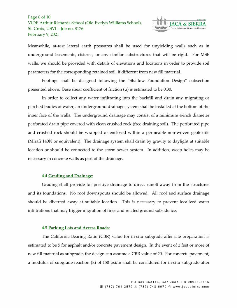
Meanwhile, at-rest lateral earth pressures shall be used for unyielding walls such as in
underground basements, cisterns, or any similar substructures that will be rigid. For MSE
walls, we should be provided with details of elevations and locations in order to provide soil
parameters for the corresponding retained soil, if different from new fill material.
Footings shall be designed following the “Shallow Foundation Design” subsection
presented above. Base shear coefficient of friction (μ) is estimated to be 0.30.
In order to collect any water infiltrating into the backfill and drain any migrating or
perched bodies of water, an underground drainage system shall be installed at the bottom of the
inner face of the walls. The underground drainage may consist of a minimum 4-inch diameter
perforated drain pipe covered with clean crushed rock (free draining soil). The perforated pipe
and crushed rock should be wrapped or enclosed within a permeable non-woven geotextile
(Mirafi 140N or equivalent). The drainage system shall drain by gravity to daylight at suitable
location or should be connected to the storm sewer system. In addition, weep holes may be
necessary in concrete walls as part of the drainage.
4.4 Grading and Drainage:
Grading shall provide for positive drainage to direct runoff away from the structures
and its foundations. No roof downspouts should be allowed. All roof and surface drainage
should be diverted away at suitable location. This is necessary to prevent localized water
infiltrations that may trigger migration of fines and related ground subsidence.
4.5 Parking Lots and Access Roads:
The California Bearing Ratio (CBR) value for in-situ subgrade after site preparation is
estimated to be 5 for asphalt and/or concrete pavement design. In the event of 2 feet or more of
new fill material as subgrade, the design can assume a CBR value of 20. For concrete pavement,
a modulus of subgrade reaction (k) of 150 psi/in shall be considered for in-situ subgrade after
Page 7 of 10
VIDE Arthur Richards School (Old Evelyn Williams School),
St. Croix, USVI – Job no. 8176
February 9, 2021
P O B o x 3 6 3 1 1 6 , S a n J u a n , P R 0 0 9 3 6 - 3 1 1 6
( 7 8 7 ) 7 6 1 - 2 5 7 0 ( 7 8 7 ) 7 4 8 - 6 9 7 0 w w w . j a c a s i e r r a . c o m
site preparation and 250 psi/in for new fill subgrade. New pavement layers and thicknesses
shall be based on designed pavement section.
We recommend the performance of field CBR or Dynamic Cone Penetrometer (DCP)
tests over the prepared subgrade prior to pavement construction in order to confirm the CBR
values used in design. CBR or DCP tests should be conducted following ASTM D4429 or ASTM
D6951, respectively. The quantity and location of the tests should be coordinated with the
consultant geotechnical engineer.
4.6 Site Preparation:
Site preparation for new structures and paved areas shall consist of clearing and
grubbing, which includes removal of vegetation, topsoil, roots and foreign debris within the
upper 6 to 24 inches of subsoil. This clearing and grubbing procedure shall be extended a
minimum horizontal distance of 3 feet beyond the perimeter of new structures, where possible.
After clearing and grubbing, the exposed grade shall be roller compacted and then proof
rolled with loaded truck for detection of weak spots. Any weak spots encountered have to be
excavated and replaced with new fill material.
Site preparation works shall be coordinated with the consultant geotechnical engineer to
monitor earthwork in progress and to direct any required variations on the provided
recommendations, if deemed necessary. Different subsoil conditions may be found within the
project site area, especially in unexplored zones between and beyond boring locations.
Therefore, the final extensions of site preparation will be determined on field during earthwork
operations. A geotechnical engineering technician is recommended to monitor proper
implementation of these measures.
4.7 Excavations:
It is our opinion that excavations through existing fill material and shallow natural soils
can be performed with common excavation equipment. Any existing abandoned underground
Page 8 of 10
VIDE Arthur Richards School (Old Evelyn Williams School),
St. Croix, USVI – Job no. 8176
February 9, 2021
P O B o x 3 6 3 1 1 6 , S a n J u a n , P R 0 0 9 3 6 - 3 1 1 6
( 7 8 7 ) 7 6 1 - 2 5 7 0 ( 7 8 7 ) 7 4 8 - 6 9 7 0 w w w . j a c a s i e r r a . c o m
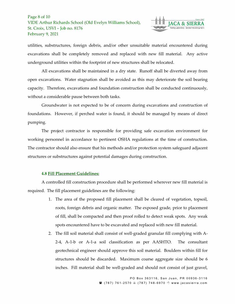
utilities, substructures, foreign debris, and/or other unsuitable material encountered during
excavations shall be completely removed and replaced with new fill material. Any active
underground utilities within the footprint of new structures shall be relocated.
All excavations shall be maintained in a dry state. Runoff shall be diverted away from
open excavations. Water stagnation shall be avoided as this may deteriorate the soil bearing
capacity. Therefore, excavations and foundation construction shall be conducted continuously,
without a considerable pause between both tasks.
Groundwater is not expected to be of concern during excavations and construction of
foundations. However, if perched water is found, it should be managed by means of direct
pumping.
The project contractor is responsible for providing safe excavation environment for
working personnel in accordance to pertinent OSHA regulations at the time of construction.
The contractor should also ensure that his methods and/or protection system safeguard adjacent
structures or substructures against potential damages during construction.
4.8 Fill Placement Guidelines:
A controlled fill construction procedure shall be performed wherever new fill material is
required. The fill placement guidelines are the following:
1. The area of the proposed fill placement shall be cleared of vegetation, topsoil,
roots, foreign debris and organic matter. The exposed grade, prior to placement
of fill, shall be compacted and then proof rolled to detect weak spots. Any weak
spots encountered have to be excavated and replaced with new fill material.
2. The fill soil material shall consist of well-graded granular fill complying with A-
2-4, A-1-b or A-1-a soil classification as per AASHTO. The consultant
geotechnical engineer should approve this soil material. Boulders within fill for
structures should be discarded. Maximum coarse aggregate size should be 6
inches. Fill material shall be well-graded and should not consist of just gravel,
Page 9 of 10
VIDE Arthur Richards School (Old Evelyn Williams School),
St. Croix, USVI – Job no. 8176
February 9, 2021
P O B o x 3 6 3 1 1 6 , S a n J u a n , P R 0 0 9 3 6 - 3 1 1 6
( 7 8 7 ) 7 6 1 - 2 5 7 0 ( 7 8 7 ) 7 4 8 - 6 9 7 0 w w w . j a c a s i e r r a . c o m
crushed stone or poorly graded sand. In-situ excavated soils can be reused for
new fill if those materials are in compliance with these requirements.
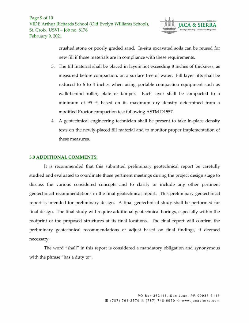
3. The fill material shall be placed in layers not exceeding 8 inches of thickness, as
measured before compaction, on a surface free of water. Fill layer lifts shall be
reduced to 6 to 4 inches when using portable compaction equipment such as
walk-behind roller, plate or tamper. Each layer shall be compacted to a
minimum of 95 % based on its maximum dry density determined from a
modified Proctor compaction test following ASTM D1557.
4. A geotechnical engineering technician shall be present to take in-place density
tests on the newly-placed fill material and to monitor proper implementation of
these measures.
5.0 ADDITIONAL COMMENTS:
It is recommended that this submitted preliminary geotechnical report be carefully
studied and evaluated to coordinate those pertinent meetings during the project design stage to
discuss the various considered concepts and to clarify or include any other pertinent
geotechnical recommendations in the final geotechnical report. This preliminary geotechnical
report is intended for preliminary design. A final geotechnical study shall be performed for
final design. The final study will require additional geotechnical borings, especially within the
footprint of the proposed structures at its final locations. The final report will confirm the
preliminary geotechnical recommendations or adjust based on final findings, if deemed
necessary.
The word “shall” in this report is considered a mandatory obligation and synonymous
with the phrase “has a duty to”.
Page 10 of 10
VIDE Arthur Richards School (Old Evelyn Williams School),
St. Croix, USVI – Job no. 8176
February 9, 2021
P O B o x 3 6 3 1 1 6 , S a n J u a n , P R 0 0 9 3 6 - 3 1 1 6
( 7 8 7 ) 7 6 1 - 2 5 7 0 ( 7 8 7 ) 7 4 8 - 6 9 7 0 w w w . j a c a s i e r r a . c o m
We wish to thank you for the opportunity of submitting this preliminary geotechnical
engineering report and remain,
Cordially yours,
JACA & SIERRA ENGINEERING, PSC
Rommel Cintrón Aponte, MSCE, PE
Enclosures
Appendix A: Figures
Appendix B: Boring Logs
Appendix C: Soil Classification Tests
Appendix A:
Figures
Figure 1: Site and boring locations in Google Earth satellite image (imagery date: 3/29/2020)
Figure 2: Site location in geologic map (Whetten, J.T., 1966, “Geology of St. Croix, U.S. Virgin Islands”, Geological Society of America, Caribbean
Geological Investigations, Memoir 98)
SITE
Appendix B:
Boring Logs
0
5
10
15
20
25
30
0.00
-1.22
-4.27
-5.79
-7.32
-8.84
0
FILL: silty sand some clay, pale yellow
FILL: silty clay some sand, dark brown, pale yellow
4
SILTY SAND some clay, loose, pale yellow, brownishyellow
Same as above... medium dense, yellowish white
14
SILTY CLAY trace sand, stiff, light yellowish brown,light brown
19
SILTY SAND some gravel, dense, yellowish brown
24
SILTY CLAY some sand, stiff, light yellowish brown
29
SANDY SILT some clay, very stiff, pale yellow, lightbrownish yellowEnd of Boring
357
334
334
224
151413
567
162121
345
8811
12
7
7
6
27
13
42
9
19
18
20
13
16
17
36
12
26
71
SUBSURFACE EXPLORATION LOGBORING NUMBER: 1
DRILLING LOGPROJECT
VIDE AR School (Old EW School)JOB
8176OF
SHEET 1
LOCATION St. Croix, USVI DRILLER/DRILL RIG J.C. Calderon / CME-55
COORDINATES DATE Started 1-12-21 Completed 1-12-21
DESCRIPTION Manuel Porrata TOP ELEVATION (FT)
GROUNDWATER (FT) Initial Not Found Final ENGINEER Rommel Cintron
DRILLING METHOD Hollow-Stem Auger 2.25" ID FINAL DEPTH (FT) 30.5
N W Qu
"SPT N" - Number of blows required to drive the sampling spoon a distance of 12 inches with a 140 lbs hammer falling 30 inches."W" - Natural moisture content in percentage of dry weight. Initial groundwater level depth."Qu" - Unconfined compressive strength in tons per square foot. Final groundwater level depth."Rc" - Core recovery in percent for each successive run. "RQD" - Rock quality designation."WH" - Sample was recovered by advancing the sampler with the weight of the hammer."P" - A P in the unconfined compressive strength test indicates the use of the pocket penetrometer.
SILTY SAND some clay, medium dense, yellowishwhite
Same as above... very dense
19
SILTY CLAY trace sand, very stiff, olive brown,brownish gray, light brown
End of Boring
344
355
14118
457
121412
2133
50/5"
669
91413
8814
8
10
19
12
26
50/5"
15
27
22
21
20
14
10
28
33
40
22
68
1.8
3.7
SUBSURFACE EXPLORATION LOGBORING NUMBER: 2
DRILLING LOGPROJECT
VIDE AR School (Old EW School)JOB
8176OF
SHEET 1
LOCATION St. Croix, USVI DRILLER/DRILL RIG J.C. Calderon / CME-55
COORDINATES DATE Started 1-12-21 Completed 1-12-21
DESCRIPTION Manuel Porrata TOP ELEVATION (FT)
GROUNDWATER (FT) Initial Not Found Final ENGINEER Rommel Cintron
DRILLING METHOD Hollow-Stem Auger 2.25" ID FINAL DEPTH (FT) 30.5
N W Qu
"SPT N" - Number of blows required to drive the sampling spoon a distance of 12 inches with a 140 lbs hammer falling 30 inches."W" - Natural moisture content in percentage of dry weight. Initial groundwater level depth."Qu" - Unconfined compressive strength in tons per square foot. Final groundwater level depth."Rc" - Core recovery in percent for each successive run. "RQD" - Rock quality designation."WH" - Sample was recovered by advancing the sampler with the weight of the hammer."P" - A P in the unconfined compressive strength test indicates the use of the pocket penetrometer.
Elev.(m)
Depth(ft)
Description
Legend
Sam
ple
Blo
ws SPT
N W Qu20 40 60 80
1 2 3 4Qu
N-W
1
0
5
10
15
20
25
30
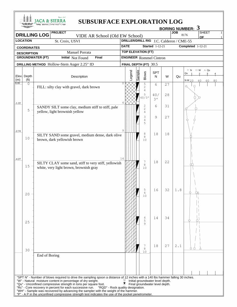
0.00
-1.22
-2.74
-4.27
0
FILL: silty clay with gravel, dark brown
4
SANDY SILT some clay, medium stiff to stiff, paleyellow, light brownish yellow
9
SILTY SAND some gravel, medium dense, dark olivebrown, dark yellowish brown
14
SILTY CLAY some sand, stiff to very stiff, yellowishwhite, very light brown, brownish gray
End of Boring
524
540/3"
224
345
8810
7810
5610
459
7810
6
40/3"
6
9
18
18
16
14
18
27
28
31
27
18
22
32
34
27
1.8
2.1
SUBSURFACE EXPLORATION LOGBORING NUMBER: 3
DRILLING LOGPROJECT
VIDE AR School (Old EW School)JOB
8176OF
SHEET 1
LOCATION St. Croix, USVI DRILLER/DRILL RIG J.C. Calderon / CME-55
COORDINATES DATE Started 1-12-21 Completed 1-12-21
DESCRIPTION Manuel Porrata TOP ELEVATION (FT)
GROUNDWATER (FT) Initial Not Found Final ENGINEER Rommel Cintron
DRILLING METHOD Hollow-Stem Auger 2.25" ID FINAL DEPTH (FT) 30.5
N W Qu
"SPT N" - Number of blows required to drive the sampling spoon a distance of 12 inches with a 140 lbs hammer falling 30 inches."W" - Natural moisture content in percentage of dry weight. Initial groundwater level depth."Qu" - Unconfined compressive strength in tons per square foot. Final groundwater level depth."Rc" - Core recovery in percent for each successive run. "RQD" - Rock quality designation."WH" - Sample was recovered by advancing the sampler with the weight of the hammer."P" - A P in the unconfined compressive strength test indicates the use of the pocket penetrometer.
SITLY SAND some clay, medium dense, pale yellow,yellowish white
14
SANDY SILT some clay, very stiff to hard, lightyellowish brown, light olive brown
End of Boring
348
556
567
101215
121615
61010
7912
52031
121521
12
11
13
27
31
20
21
51
36
19
21
20
13
13
26
28
20
45
SUBSURFACE EXPLORATION LOGBORING NUMBER: 4
DRILLING LOGPROJECT
VIDE AR School (Old EW School)JOB
8176OF
SHEET 1
LOCATION St. Croix, USVI DRILLER/DRILL RIG J.C. Calderon / CME-55
COORDINATES DATE Started 1-12-21 Completed 1-12-21
DESCRIPTION Manuel Porrata TOP ELEVATION (FT)
GROUNDWATER (FT) Initial Not Found Final ENGINEER Rommel Cintron
DRILLING METHOD Hollow-Stem Auger 2.25" ID FINAL DEPTH (FT) 30.5
N W Qu
"SPT N" - Number of blows required to drive the sampling spoon a distance of 12 inches with a 140 lbs hammer falling 30 inches."W" - Natural moisture content in percentage of dry weight. Initial groundwater level depth."Qu" - Unconfined compressive strength in tons per square foot. Final groundwater level depth."Rc" - Core recovery in percent for each successive run. "RQD" - Rock quality designation."WH" - Sample was recovered by advancing the sampler with the weight of the hammer."P" - A P in the unconfined compressive strength test indicates the use of the pocket penetrometer.
Elev.(m)
Depth(ft)
Description
Legend
Sam
ple
Blo
ws SPT
N W Qu20 40 60 80
1 2 3 4Qu
N-W
1
0
5
10
15
20
25
30
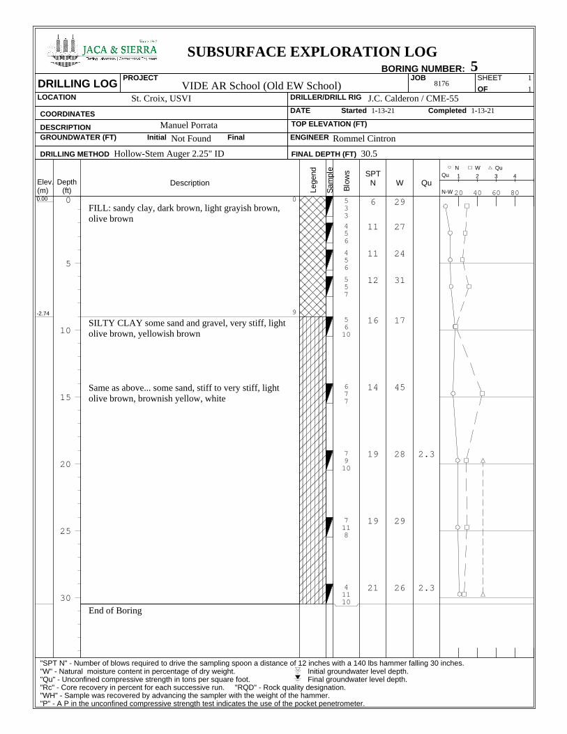
0.00
-2.74
0
FILL: sandy clay, dark brown, light grayish brown,olive brown
9
SILTY CLAY some sand and gravel, very stiff, lightolive brown, yellowish brown
Same as above... some sand, stiff to very stiff, lightolive brown, brownish yellow, white
End of Boring
533
456
456
557
5610
677
7910
7118
41110
6
11
11
12
16
14
19
19
21
29
27
24
31
17
45
28
29
26
2.3
2.3
SUBSURFACE EXPLORATION LOGBORING NUMBER: 5
DRILLING LOGPROJECT
VIDE AR School (Old EW School)JOB
8176OF
SHEET 1
LOCATION St. Croix, USVI DRILLER/DRILL RIG J.C. Calderon / CME-55
COORDINATES DATE Started 1-13-21 Completed 1-13-21
DESCRIPTION Manuel Porrata TOP ELEVATION (FT)
GROUNDWATER (FT) Initial Not Found Final ENGINEER Rommel Cintron
DRILLING METHOD Hollow-Stem Auger 2.25" ID FINAL DEPTH (FT) 30.5
N W Qu
"SPT N" - Number of blows required to drive the sampling spoon a distance of 12 inches with a 140 lbs hammer falling 30 inches."W" - Natural moisture content in percentage of dry weight. Initial groundwater level depth."Qu" - Unconfined compressive strength in tons per square foot. Final groundwater level depth."Rc" - Core recovery in percent for each successive run. "RQD" - Rock quality designation."WH" - Sample was recovered by advancing the sampler with the weight of the hammer."P" - A P in the unconfined compressive strength test indicates the use of the pocket penetrometer.
Elev.(m)
Depth(ft)
Description
Legend
Sam
ple
Blo
ws SPT
N W Qu20 40 60 80
1 2 3 4Qu
N-W
1
0
5
10
15
20
25
30
0.00
-0.61
-4.27
-5.79
0
FILL: silty clay trace sand, brownish gray, yellowishbrown, light brown
2
SILTY CLAY trace sand, stiff, brownish gray,yellowish brown, light brown
14
SILTY SAND with gravel, very dense, olive brown
19
SILTY CLAY trace sand, very stiff, light yellowishbrown, light olive brown, grayish brown
Same as above... some sand
End of Boring
1344
568
355
355
456
152729
111313
7720
5622
8
14
10
10
11
56
26
27
28
19
22
38
34
27
11
61
29
33
SUBSURFACE EXPLORATION LOGBORING NUMBER: 6
DRILLING LOGPROJECT
VIDE AR School (Old EW School)JOB
8176OF
SHEET 1
LOCATION St. Croix, USVI DRILLER/DRILL RIG J.C. Calderon / CME-55
COORDINATES DATE Started 1-13-21 Completed 1-13-21
DESCRIPTION Manuel Porrata TOP ELEVATION (FT)
GROUNDWATER (FT) Initial Not Found Final ENGINEER Rommel Cintron
DRILLING METHOD Hollow-Stem Auger 2.25" ID FINAL DEPTH (FT) 30.5
N W Qu
"SPT N" - Number of blows required to drive the sampling spoon a distance of 12 inches with a 140 lbs hammer falling 30 inches."W" - Natural moisture content in percentage of dry weight. Initial groundwater level depth."Qu" - Unconfined compressive strength in tons per square foot. Final groundwater level depth."Rc" - Core recovery in percent for each successive run. "RQD" - Rock quality designation."WH" - Sample was recovered by advancing the sampler with the weight of the hammer."P" - A P in the unconfined compressive strength test indicates the use of the pocket penetrometer.
Elev.(m)
Depth(ft)
Description
Legend
Sam
ple
Blo
ws SPT
N W Qu20 40 60 80
1 2 3 4Qu
N-W
1
0
5
10
15
20
25
30
0.00
-1.83
0
SANDY SILT some clay, medium stiff to stiff, paleyellow, light brownish yellow
6
SILTY CLAY some sand, very stiff, yellowish brown,light brown, brownish gray
End of Boring
975
333
333
7810
679
12
6
6
18
16
22
23
30
26
26 1.8
SUBSURFACE EXPLORATION LOGBORING NUMBER: 7
DRILLING LOGPROJECT
VIDE AR School (Old EW School)JOB
8176OF
SHEET 1
LOCATION St. Croix, USVI DRILLER/DRILL RIG J.C. Calderon / CME-55
COORDINATES DATE Started 1-14-21 Completed 1-14-21
DESCRIPTION Manuel Porrata TOP ELEVATION (FT)
GROUNDWATER (FT) Initial Not Found Final ENGINEER Rommel Cintron
DRILLING METHOD Hollow-Stem Auger 2.25" ID FINAL DEPTH (FT) 10.5
N W Qu
"SPT N" - Number of blows required to drive the sampling spoon a distance of 12 inches with a 140 lbs hammer falling 30 inches."W" - Natural moisture content in percentage of dry weight. Initial groundwater level depth."Qu" - Unconfined compressive strength in tons per square foot. Final groundwater level depth."Rc" - Core recovery in percent for each successive run. "RQD" - Rock quality designation."WH" - Sample was recovered by advancing the sampler with the weight of the hammer."P" - A P in the unconfined compressive strength test indicates the use of the pocket penetrometer.
Elev.(m)
Depth(ft)
Description
Legend
Sam
ple
Blo
ws SPT
N W Qu20 40 60 80
1 2 3 4Qu
N-W
1
0
5
10
15
20
25
30
0.00
-0.61
-2.74
0
FILL: sandy clay trace gravel, stiff, whitish brown,olive brown
2
SANDY SILT some clay, medium stiff to stiff, paleyellow, light olive brown, light yellowish brown
9
SILTY CLAY trace sand, stiff, olive brown, white
End of Boring
1366
654
333
345
788
12
9
6
9
16
19
23
23
31
33
SUBSURFACE EXPLORATION LOGBORING NUMBER: 8
DRILLING LOGPROJECT
VIDE AR School (Old EW School)JOB
8176OF
SHEET 1
LOCATION St. Croix, USVI DRILLER/DRILL RIG J.C. Calderon / CME-55
COORDINATES DATE Started 1-13-21 Completed 1-13-21
DESCRIPTION Manuel Porrata TOP ELEVATION (FT)
GROUNDWATER (FT) Initial Not Found Final ENGINEER Rommel Cintron
DRILLING METHOD Hollow-Stem Auger 2.25" ID FINAL DEPTH (FT) 10.5
N W Qu
"SPT N" - Number of blows required to drive the sampling spoon a distance of 12 inches with a 140 lbs hammer falling 30 inches."W" - Natural moisture content in percentage of dry weight. Initial groundwater level depth."Qu" - Unconfined compressive strength in tons per square foot. Final groundwater level depth."Rc" - Core recovery in percent for each successive run. "RQD" - Rock quality designation."WH" - Sample was recovered by advancing the sampler with the weight of the hammer."P" - A P in the unconfined compressive strength test indicates the use of the pocket penetrometer.
Elev.(m)
Depth(ft)
Description
Legend
Sam
ple
Blo
ws SPT
N W Qu20 40 60 80
1 2 3 4Qu
N-W
1
0
5
10
15
20
25
30
0.00 0
SILTY CLAY some sand, medium stiff to stiff,brownish gray, light olive brown, dark brown
Same as above... yellowish brown
End of Boring
1755
455
223
225
3510
10
10
5
7
15
26
24
32
32
16 1.6
SUBSURFACE EXPLORATION LOGBORING NUMBER: 9
DRILLING LOGPROJECT
VIDE AR School (Old EW School)JOB
8176OF
SHEET 1
LOCATION St. Croix, USVI DRILLER/DRILL RIG J.C. Calderon / CME-55
COORDINATES DATE Started 1-14-21 Completed 1-14-21
DESCRIPTION Manuel Porrata TOP ELEVATION (FT)
GROUNDWATER (FT) Initial Not Found Final ENGINEER Rommel Cintron
DRILLING METHOD Hollow-Stem Auger 2.25" ID FINAL DEPTH (FT) 10.5
N W Qu
"SPT N" - Number of blows required to drive the sampling spoon a distance of 12 inches with a 140 lbs hammer falling 30 inches."W" - Natural moisture content in percentage of dry weight. Initial groundwater level depth."Qu" - Unconfined compressive strength in tons per square foot. Final groundwater level depth."Rc" - Core recovery in percent for each successive run. "RQD" - Rock quality designation."WH" - Sample was recovered by advancing the sampler with the weight of the hammer."P" - A P in the unconfined compressive strength test indicates the use of the pocket penetrometer.
Elev.(m)
Depth(ft)
Description
Legend
Sam
ple
Blo
ws SPT
N W Qu20 40 60 80
1 2 3 4Qu
N-W
1
Appendix C:
Soil Classification Tests
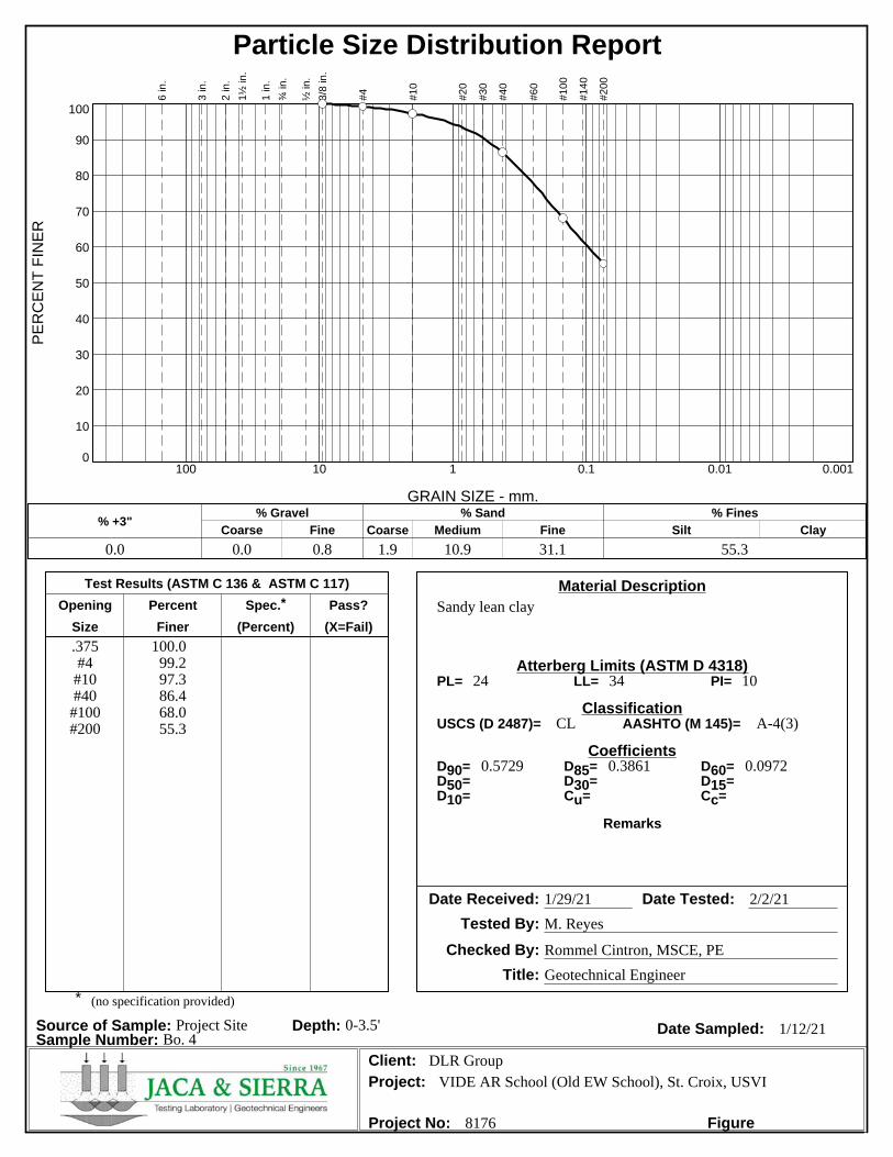
Particle Size Distribution ReportP
ER
CE
NT
FIN
ER
0
10
20
30
40
50
60
70
80
90
100
GRAIN SIZE - mm.
0.0010.010.1110100
% +3"Coarse
% Gravel
Fine Coarse Medium
% Sand
Fine Silt
% Fines
Clay
0.0 0.0 0.8 1.9 10.9 31.1 55.3
6 in
.
3 in
.
2 in
.
1½
in
.
1 in
.
¾ in
.
½ in
.
3/8
in
.
#4
#1
0
#2
0
#3
0
#4
0
#6
0
#1
00
#1
40
#2
00
Test Results (ASTM C 136 & ASTM C 117)
Opening Percent Spec.* Pass?
Size Finer (Percent) (X=Fail)
Material Description
Atterberg Limits (ASTM D 4318)
Classification
Coefficients
Date Received: Date Tested:
Tested By:
Checked By:
Title:
Date Sampled:Source of Sample: Project Site Depth: 0-3.5'Sample Number: Bo. 4
Client:Project:
Project No: Figure
Sandy lean clay
.375#4#10#40#100#200
100.099.297.386.468.055.3
24 34 10
CL A-4(3)
0.5729 0.3861 0.0972
1/29/21 2/2/21
M. Reyes
Rommel Cintron, MSCE, PE
Geotechnical Engineer
1/12/21
DLR GroupVIDE AR School (Old EW School), St. Croix, USVI
8176
PL= LL= PI=
USCS (D 2487)= AASHTO (M 145)=
D90= D85= D60=D50= D30= D15=D10= Cu= Cc=
Remarks
* (no specification provided)
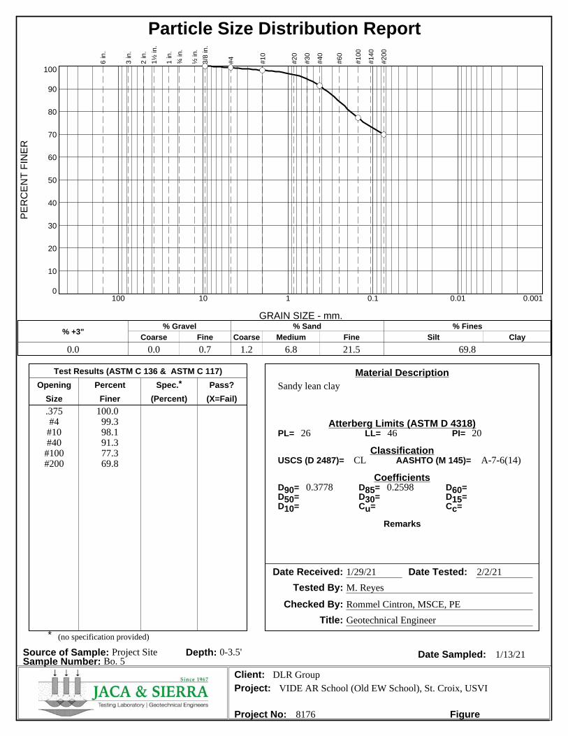
Particle Size Distribution ReportP
ER
CE
NT
FIN
ER
0
10
20
30
40
50
60
70
80
90
100
GRAIN SIZE - mm.
0.0010.010.1110100
% +3"Coarse
% Gravel
Fine Coarse Medium
% Sand
Fine Silt
% Fines
Clay
0.0 0.0 0.7 1.2 6.8 21.5 69.8
6 in
.
3 in
.
2 in
.
1½
in
.
1 in
.
¾ in
.
½ in
.
3/8
in
.
#4
#1
0
#2
0
#3
0
#4
0
#6
0
#1
00
#1
40
#2
00
Test Results (ASTM C 136 & ASTM C 117)
Opening Percent Spec.* Pass?
Size Finer (Percent) (X=Fail)
Material Description
Atterberg Limits (ASTM D 4318)
Classification
Coefficients
Date Received: Date Tested:
Tested By:
Checked By:
Title:
Date Sampled:Source of Sample: Project Site Depth: 0-3.5'Sample Number: Bo. 5
Client:Project:
Project No: Figure
Sandy lean clay
.375#4#10#40#100#200
100.099.398.191.377.369.8
26 46 20
CL A-7-6(14)
0.3778 0.2598
1/29/21 2/2/21
M. Reyes
Rommel Cintron, MSCE, PE
Geotechnical Engineer
1/13/21
DLR GroupVIDE AR School (Old EW School), St. Croix, USVI
8176
PL= LL= PI=
USCS (D 2487)= AASHTO (M 145)=
D90= D85= D60=D50= D30= D15=D10= Cu= Cc=
Remarks
* (no specification provided)
Particle Size Distribution ReportP
ER
CE
NT
FIN
ER
0
10
20
30
40
50
60
70
80
90
100
GRAIN SIZE - mm.
0.0010.010.1110100
% +3"Coarse
% Gravel
Fine Coarse Medium
% Sand
Fine Silt
% Fines
Clay
0.0 0.0 0.1 0.3 1.0 4.1 94.5
6 in
.
3 in
.
2 in
.
1½
in
.
1 in
.
¾ in
.
½ in
.
3/8
in
.
#4
#1
0
#2
0
#3
0
#4
0
#6
0
#1
00
#1
40
#2
00
Test Results (ASTM C 136 & ASTM C 117)
Opening Percent Spec.* Pass?
Size Finer (Percent) (X=Fail)
Material Description
Atterberg Limits (ASTM D 4318)
Classification
Coefficients
Date Received: Date Tested:
Tested By:
Checked By:
Title:
Date Sampled:Source of Sample: Project Site Depth: 0-3.5'Sample Number: Bo. 6
Client:Project:
Project No: Figure
Lean clay
.375#4#10#40#100#200
100.099.999.698.697.494.5
21 33 12
CL A-6(11)
1/29/21 2/2/21
M. Reyes
Rommel Cintron, MSCE, PE
Geotechnical Engineer
1/13/21
DLR GroupVIDE AR School (Old EW School), St. Croix, USVI
8176
PL= LL= PI=
USCS (D 2487)= AASHTO (M 145)=
D90= D85= D60=D50= D30= D15=D10= Cu= Cc=
Remarks
* (no specification provided)
Particle Size Distribution ReportP
ER
CE
NT
FIN
ER
0
10
20
30
40
50
60
70
80
90
100
GRAIN SIZE - mm.
0.0010.010.1110100
% +3"Coarse
% Gravel
Fine Coarse Medium
% Sand
Fine Silt
% Fines
Clay
0.0 0.0 0.4 1.9 8.6 21.0 68.1
6 in
.
3 in
.
2 in
.
1½
in
.
1 in
.
¾ in
.
½ in
.
3/8
in
.
#4
#1
0
#2
0
#3
0
#4
0
#6
0
#1
00
#1
40
#2
00
Test Results (ASTM C 136 & ASTM C 117)
Opening Percent Spec.* Pass?
Size Finer (Percent) (X=Fail)
Material Description
Atterberg Limits (ASTM D 4318)
Classification
Coefficients
Date Received: Date Tested:
Tested By:
Checked By:
Title:
Date Sampled:Source of Sample: Project Site Depth: 0-3.5'Sample Number: Bo. 7
Client:Project:
Project No: Figure
Sandy silty clay
.375#4#10#40#100#200
100.099.697.789.177.368.1
22 28 6
CL-ML A-4(2)
0.4712 0.2836
1/29/21 2/2/21
M. Reyes
Rommel Cintron, MSCE, PE
Geotechnical Engineer
1/14/21
DLR GroupVIDE AR School (Old EW School), St. Croix, USVI
8176
PL= LL= PI=
USCS (D 2487)= AASHTO (M 145)=
D90= D85= D60=D50= D30= D15=D10= Cu= Cc=
Remarks
* (no specification provided)
R
U
M
F
A
C
T
O
R
Y
R
D
.
1
1
0
1
1
5
1
0
5
1
0
0
1
2
0
1
2
5
9
5
95
9
0
100
1
0
5
110
1
1
0
115
1
0
5
120
1
1
5
1
1
0
8
5
9
0
1
1
0
AutoCAD SHX Text
St Anns
AutoCAD SHX Text
Sch
AutoCAD SHX Text
Ruins
AutoCAD SHX Text
Blessing
AutoCAD SHX Text
S A I N
AutoCAD SHX Text
PRINCE
AutoCAD SHX Text
Experimental
AutoCAD SHX Text
202
AutoCAD SHX Text
70
AutoCAD SHX Text
66
AutoCAD SHX Text
64
AutoCAD SHX Text
Burk
AutoCAD SHX Text
Castle
AutoCAD SHX Text
ROAD
AutoCAD SHX Text
Grove
AutoCAD SHX Text
Golden
AutoCAD SHX Text
Negro Bay
AutoCAD SHX Text
Airport
AutoCAD SHX Text
Alexander Hamilton
AutoCAD SHX Text
Envy
AutoCAD SHX Text
70
AutoCAD SHX Text
81
AutoCAD SHX Text
BM
AutoCAD SHX Text
Ruins
AutoCAD SHX Text
66
AutoCAD SHX Text
64
AutoCAD SHX Text
Kingshill
AutoCAD SHX Text
Profit
AutoCAD SHX Text
Anguilla
AutoCAD SHX Text
CENTERLINE
AutoCAD SHX Text
90
AutoCAD SHX Text
110
AutoCAD SHX Text
Bethlehem
AutoCAD SHX Text
Upper
AutoCAD SHX Text
64
AutoCAD SHX Text
64
AutoCAD SHX Text
64
AutoCAD SHX Text
66
AutoCAD SHX Text
Station
AutoCAD SHX Text
Airway
AutoCAD SHX Text
Manning
AutoCAD SHX Text
Beacon
AutoCAD SHX Text
Catchment
AutoCAD SHX Text
Basin
AutoCAD SHX Text
Hamilton
AutoCAD SHX Text
Alexander
AutoCAD SHX Text
Airport
AutoCAD SHX Text
Bay
AutoCAD SHX Text
Manning
AutoCAD SHX Text
Racetrack
AutoCAD SHX Text
CHRISTIANSTED JURISDICTION
AutoCAD SHX Text
FREDRIKSTED JURISDICTION
AutoCAD SHX Text
Ruins
AutoCAD SHX Text
Town
AutoCAD SHX Text
Spanish
AutoCAD SHX Text
x
AutoCAD SHX Text
Ruins
AutoCAD SHX Text
Annaberg
AutoCAD SHX Text
Ruins
AutoCAD SHX Text
66
AutoCAD SHX Text
Ruins
AutoCAD SHX Text
Cem
AutoCAD SHX Text
172
AutoCAD SHX Text
73
AutoCAD SHX Text
Krause
AutoCAD SHX Text
110
AutoCAD SHX Text
Water
AutoCAD SHX Text
Molasses
AutoCAD SHX Text
Mtn
AutoCAD SHX Text
Blue
AutoCAD SHX Text
Hermitage
AutoCAD SHX Text
Mt Pleasant
AutoCAD SHX Text
Jealousy
AutoCAD SHX Text
Ruins
AutoCAD SHX Text
278
AutoCAD SHX Text
72
AutoCAD SHX Text
Ruins
AutoCAD SHX Text
FREDRIKSTED JURISDICTION
AutoCAD SHX Text
CHRISTIANSTED JURISDICTION
AutoCAD SHX Text
Ruins
AutoCAD SHX Text
Fountain
AutoCAD SHX Text
Little
AutoCAD SHX Text
Ruins
AutoCAD SHX Text
Cem
AutoCAD SHX Text
Work
AutoCAD SHX Text
Old
AutoCAD SHX Text
Bethlehem
AutoCAD SHX Text
Kingshill
AutoCAD SHX Text
Sch
AutoCAD SHX Text
Bijou
AutoCAD SHX Text
Mon
AutoCAD SHX Text
Water
AutoCAD SHX Text
Ruins
AutoCAD SHX Text
707
AutoCAD SHX Text
73
AutoCAD SHX Text
73
AutoCAD SHX Text
72
AutoCAD SHX Text
Ruins
AutoCAD SHX Text
125
AutoCAD SHX Text
122
AutoCAD SHX Text
108
AutoCAD SHX Text
Friedensfeld
AutoCAD SHX Text
Salt
AutoCAD SHX Text
ROAD
AutoCAD SHX Text
Fredensborg
AutoCAD SHX Text
La Reine
AutoCAD SHX Text
Glynn
AutoCAD SHX Text
Ruins
AutoCAD SHX Text
Clifton
AutoCAD SHX Text
Hill
AutoCAD SHX Text
Slob
AutoCAD SHX Text
103
AutoCAD SHX Text
Esperance
AutoCAD SHX Text
Bonne
AutoCAD SHX Text
75
AutoCAD SHX Text
709
AutoCAD SHX Text
75
AutoCAD SHX Text
707
AutoCAD SHX Text
72
AutoCAD SHX Text
135
AutoCAD SHX Text
Ruins
AutoCAD SHX Text
Ruins
AutoCAD SHX Text
Cem
AutoCAD SHX Text
Cem
AutoCAD SHX Text
BM
AutoCAD SHX Text
188
AutoCAD SHX Text
Ruins
AutoCAD SHX Text
Castle
AutoCAD SHX Text
Lagoon
AutoCAD SHX Text
Long
AutoCAD SHX Text
Channel
AutoCAD SHX Text
Channel
AutoCAD SHX Text
Bay
AutoCAD SHX Text
Reef
AutoCAD SHX Text
Limestone
AutoCAD SHX Text
Figtree Hill
AutoCAD SHX Text
Jerusalem and
AutoCAD SHX Text
143x
AutoCAD SHX Text
Cottage
AutoCAD SHX Text
X
AutoCAD SHX Text
66
AutoCAD SHX Text
83
AutoCAD SHX Text
68
AutoCAD SHX Text
Flat
AutoCAD SHX Text
Tidal
AutoCAD SHX Text
Hope
AutoCAD SHX Text
68
AutoCAD SHX Text
68
AutoCAD SHX Text
Ruins
AutoCAD SHX Text
Ruins
AutoCAD SHX Text
148
AutoCAD SHX Text
Coakley
AutoCAD SHX Text
Ruins
AutoCAD SHX Text
81
AutoCAD SHX Text
Garden
AutoCAD SHX Text
Cassava
AutoCAD SHX Text
C R O I X
AutoCAD SHX Text
and Belvedere
AutoCAD SHX Text
Q U E E N
AutoCAD SHX Text
Rattan
AutoCAD SHX Text
488
AutoCAD SHX Text
79
AutoCAD SHX Text
66
AutoCAD SHX Text
T
AutoCAD SHX Text
Diamond
AutoCAD SHX Text
Barren
AutoCAD SHX Text
Spot
AutoCAD SHX Text
Strawberry Hill
AutoCAD SHX Text
Ruins
AutoCAD SHX Text
146
AutoCAD SHX Text
X
AutoCAD SHX Text
Limetree
AutoCAD SHX Text
348X
AutoCAD SHX Text
Fancy
AutoCAD SHX Text
Marys
AutoCAD SHX Text
Ruby
AutoCAD SHX Text
79
AutoCAD SHX Text
709
AutoCAD SHX Text
Ruins
AutoCAD SHX Text
141
AutoCAD SHX Text
BM
AutoCAD SHX Text
107
AutoCAD SHX Text
Ruins
AutoCAD SHX Text
70
AutoCAD SHX Text
709
AutoCAD SHX Text
Ruins
AutoCAD SHX Text
485
AutoCAD SHX Text
500X
AutoCAD SHX Text
74
AutoCAD SHX Text
136
AutoCAD SHX Text
Peters
AutoCAD SHX Text
NATIONAL
AutoCAD SHX Text
207
AutoCAD SHX Text
Sion Farm
AutoCAD SHX Text
Ruins
AutoCAD SHX Text
Ruins
AutoCAD SHX Text
Hill
AutoCAD SHX Text
Sion
AutoCAD SHX Text
Ruins
AutoCAD SHX Text
Ruins
AutoCAD SHX Text
81
AutoCAD SHX Text
811
AutoCAD SHX Text
81
AutoCAD SHX Text
81
AutoCAD SHX Text
CHRISTIANSTEAD
AutoCAD SHX Text
76
AutoCAD SHX Text
and Sallys Fancy
AutoCAD SHX Text
Saint Georges
AutoCAD SHX Text
Sch
AutoCAD SHX Text
Diamond
AutoCAD SHX Text
Zion
AutoCAD SHX Text
RUINS
AutoCAD SHX Text
RUAN BAY
AutoCAD SHX Text
20
AutoCAD SHX Text
LONG POINT BAY
AutoCAD SHX Text
LONG POINT
AutoCAD SHX Text
SOUTH BASE
AutoCAD SHX Text
HOGENSBORG
AutoCAD SHX Text
RUINS
AutoCAD SHX Text
CENTERLINE ROAD
AutoCAD SHX Text
59
AutoCAD SHX Text
127
AutoCAD SHX Text
BM
AutoCAD SHX Text
Waldberggaard
AutoCAD SHX Text
Hope
AutoCAD SHX Text
Mountain
AutoCAD SHX Text
Ruins
AutoCAD SHX Text
70
AutoCAD SHX Text
CANE
AutoCAD SHX Text
44
AutoCAD SHX Text
WILLIAMS DELIGHT
AutoCAD SHX Text
128
AutoCAD SHX Text
125
AutoCAD SHX Text
129
AutoCAD SHX Text
ENFIELD GREEN
AutoCAD SHX Text
BETTY'S HOPE
AutoCAD SHX Text
RUINS
AutoCAD SHX Text
Paradise
AutoCAD SHX Text
69
AutoCAD SHX Text
Ch
AutoCAD SHX Text
St Lukes
AutoCAD SHX Text
160
AutoCAD SHX Text
705
AutoCAD SHX Text
x
AutoCAD SHX Text
90
AutoCAD SHX Text
Ruins
AutoCAD SHX Text
CENTERLINE
AutoCAD SHX Text
Plessen
AutoCAD SHX Text
Ch
AutoCAD SHX Text
St Josephs
AutoCAD SHX Text
108
AutoCAD SHX Text
Ch
AutoCAD SHX Text
116
AutoCAD SHX Text
135
AutoCAD SHX Text
Pleasant
AutoCAD SHX Text
Ruins
AutoCAD SHX Text
705
AutoCAD SHX Text
64
AutoCAD SHX Text
RUINS
AutoCAD SHX Text
DIAMOND
AutoCAD SHX Text
PRINCE
AutoCAD SHX Text
Love
AutoCAD SHX Text
Lower
AutoCAD SHX Text
Ruins
AutoCAD SHX Text
69
AutoCAD SHX Text
COOPER
AutoCAD SHX Text
Quarry
AutoCAD SHX Text
Hard Labour
AutoCAD SHX Text
FREDRIKSTED JURISDICTION
AutoCAD SHX Text
CHRISTIANSTED JURISDICTION
AutoCAD SHX Text
Ruins
AutoCAD SHX Text
MOUNT STEWART
AutoCAD SHX Text
Mother of Perpetual Help
AutoCAD SHX Text
Mountpellier
AutoCAD SHX Text
BODKIN
AutoCAD SHX Text
798
AutoCAD SHX Text
Allandale
AutoCAD SHX Text
Springfield
AutoCAD SHX Text
Two Friends
AutoCAD SHX Text
Ch
AutoCAD SHX Text
Ruins
AutoCAD SHX Text
Ruins
AutoCAD SHX Text
516
AutoCAD SHX Text
76
AutoCAD SHX Text
RUINS
AutoCAD SHX Text
78
AutoCAD SHX Text
FOUNTAIN
AutoCAD SHX Text
Quarry
AutoCAD SHX Text
Upper Love
AutoCAD SHX Text
RUINS
AutoCAD SHX Text
PARASOL
AutoCAD SHX Text
72
AutoCAD SHX Text
Place
AutoCAD SHX Text
Grove
AutoCAD SHX Text
640
AutoCAD SHX Text
172
AutoCAD SHX Text
193
AutoCAD SHX Text
194
AutoCAD SHX Text
69
AutoCAD SHX Text
RUINS
AutoCAD SHX Text
River
AutoCAD SHX Text
69
AutoCAD SHX Text
Coble
AutoCAD SHX Text
210
AutoCAD SHX Text
Ruins
AutoCAD SHX Text
Adventure
AutoCAD SHX Text
Tower
AutoCAD SHX Text
Ch
AutoCAD SHX Text
Holy Cross
AutoCAD SHX Text
SITE LOCATION
AutoCAD SHX Text
PWD 5218-C
AutoCAD SHX Text
PWD 3067-A
AutoCAD SHX Text
PWD 4713
AutoCAD SHX Text
80.60'
AutoCAD SHX Text
S11°20'00"E
AutoCAD SHX Text
N77°28'00"E
AutoCAD SHX Text
199.36'
AutoCAD SHX Text
S11°20'00"E
AutoCAD SHX Text
93.30'
AutoCAD SHX Text
S11°20'00"E
AutoCAD SHX Text
N77°28'00"E
AutoCAD SHX Text
199.36'
AutoCAD SHX Text
199.36'
AutoCAD SHX Text
N77°28'00"E
AutoCAD SHX Text
N77°28'00"E
AutoCAD SHX Text
N77°28'00"E
AutoCAD SHX Text
N77°28'00"E
AutoCAD SHX Text
199.36'
AutoCAD SHX Text
N77°28'00"E
AutoCAD SHX Text
199.36'
AutoCAD SHX Text
S11°20'00"E
AutoCAD SHX Text
75.00'
AutoCAD SHX Text
S11°20'00"E
AutoCAD SHX Text
S11°20'00"E
AutoCAD SHX Text
75.00'
AutoCAD SHX Text
75.00'
AutoCAD SHX Text
75.00'
AutoCAD SHX Text
S11°20'00"E
AutoCAD SHX Text
199.36'
AutoCAD SHX Text
199.36'
AutoCAD SHX Text
R=20.00 L=31.82
AutoCAD SHX Text
79.26'
AutoCAD SHX Text
N77°28'00"E
AutoCAD SHX Text
N11°20'00"W
AutoCAD SHX Text
124.00'
AutoCAD SHX Text
75.00'
AutoCAD SHX Text
N77°28'00"E
AutoCAD SHX Text
199.36'
AutoCAD SHX Text
N77°28'00"E
AutoCAD SHX Text
199.36'
AutoCAD SHX Text
N77°28'00"E
AutoCAD SHX Text
R=20.00 L=31.00
AutoCAD SHX Text
S11°20'00"E
AutoCAD SHX Text
81.40'
AutoCAD SHX Text
101.02'
AutoCAD SHX Text
99.67'
AutoCAD SHX Text
S11°20'00"E
AutoCAD SHX Text
R=20.00 L=31.07
AutoCAD SHX Text
80.07'
AutoCAD SHX Text
R=20.00 L=31.55
AutoCAD SHX Text
85.60'
AutoCAD SHX Text
S11°20'00"E
AutoCAD SHX Text
S11°16'32"E
AutoCAD SHX Text
85.27'
AutoCAD SHX Text
N11°28'00"W
AutoCAD SHX Text
S77°34'00"W
AutoCAD SHX Text
N11°28'00"W
AutoCAD SHX Text
134.00'
AutoCAD SHX Text
S11°16'32"E
AutoCAD SHX Text
85.27'
AutoCAD SHX Text
85.27'
AutoCAD SHX Text
N11°28'00"W
AutoCAD SHX Text
110.00'
AutoCAD SHX Text
S11°16'32"E
AutoCAD SHX Text
99.09'
AutoCAD SHX Text
S78°43'28"W
AutoCAD SHX Text
S11°16'32"E
AutoCAD SHX Text
85.27'
AutoCAD SHX Text
85.27'
AutoCAD SHX Text
123.85'
AutoCAD SHX Text
124.13'
AutoCAD SHX Text
S78°43'28"W
AutoCAD SHX Text
S11°16'32"E
AutoCAD SHX Text
85.27'
AutoCAD SHX Text
85.27'
AutoCAD SHX Text
N11°28'00"W
AutoCAD SHX Text
S11°16'32"E
AutoCAD SHX Text
85.27'
AutoCAD SHX Text
85.27'
AutoCAD SHX Text
N11°28'00"W
AutoCAD SHX Text
123.28'
AutoCAD SHX Text
S78°43'28"W
AutoCAD SHX Text
123.56'
AutoCAD SHX Text
S78°43'28"W
AutoCAD SHX Text
S11°16'32"E
AutoCAD SHX Text
85.27'
AutoCAD SHX Text
85.27'
AutoCAD SHX Text
N11°28'00"W
AutoCAD SHX Text
S78°43'28"W
AutoCAD SHX Text
S11°16'32"E
AutoCAD SHX Text
85.27'
AutoCAD SHX Text
122.99'
AutoCAD SHX Text
122.71'
AutoCAD SHX Text
S78°43'28"W
AutoCAD SHX Text
85.27'
AutoCAD SHX Text
N11°28'00"W
AutoCAD SHX Text
85.27'
AutoCAD SHX Text
121.57'
AutoCAD SHX Text
S78°43'28"W
AutoCAD SHX Text
S78°43'28"W
AutoCAD SHX Text
S11°16'32"E
AutoCAD SHX Text
85.27'
AutoCAD SHX Text
S11°16'32"E
AutoCAD SHX Text
S11°16'32"E
AutoCAD SHX Text
85.27'
AutoCAD SHX Text
N11°28'00"W
AutoCAD SHX Text
N11°28'00"W
AutoCAD SHX Text
122.42'
AutoCAD SHX Text
S78°43'28"W
AutoCAD SHX Text
122.14'
AutoCAD SHX Text
S78°43'28"W
AutoCAD SHX Text
85.27'
AutoCAD SHX Text
121.85'
AutoCAD SHX Text
85.27'
AutoCAD SHX Text
N11°28'00"W
AutoCAD SHX Text
85.27'
AutoCAD SHX Text
N11°28'00"W
AutoCAD SHX Text
N11°28'00"W
AutoCAD SHX Text
134.00'
AutoCAD SHX Text
121.29'
AutoCAD SHX Text
S78°43'28"W
AutoCAD SHX Text
S78°43'28"W
AutoCAD SHX Text
121.00'
AutoCAD SHX Text
85.27'
AutoCAD SHX Text
N11°28'00"W
AutoCAD SHX Text
85.27'
AutoCAD SHX Text
134.00'
AutoCAD SHX Text
N11°28'00"W
AutoCAD SHX Text
N11°32'00"W
AutoCAD SHX Text
854.27'
AutoCAD SHX Text
96.21'
AutoCAD SHX Text
N11°28'00"W
AutoCAD SHX Text
N58°50'54"E
AutoCAD SHX Text
134.77'
AutoCAD SHX Text
N31°01'32"E
AutoCAD SHX Text
70.86'
AutoCAD SHX Text
141.81'
AutoCAD SHX Text
51.95'
AutoCAD SHX Text
32.87'
AutoCAD SHX Text
N78°32'E
AutoCAD SHX Text
N11°28'W
AutoCAD SHX Text
N02°09'15"W
AutoCAD SHX Text
95.73'
AutoCAD SHX Text
32.29'
AutoCAD SHX Text
75.58'
AutoCAD SHX Text
N77°22'00"E
AutoCAD SHX Text
61.13'
AutoCAD SHX Text
25.00'
AutoCAD SHX Text
N31°50'53"E
AutoCAD SHX Text
N77°22'00"E
AutoCAD SHX Text
72.88'
AutoCAD SHX Text
96.21'
AutoCAD SHX Text
109.14'
AutoCAD SHX Text
S02°09'15"E
AutoCAD SHX Text
109.14'
AutoCAD SHX Text
96.21'
AutoCAD SHX Text
S02°09'15"E
AutoCAD SHX Text
109.14'
AutoCAD SHX Text
96.21'
AutoCAD SHX Text
96.21'
AutoCAD SHX Text
S02°09'15"E
AutoCAD SHX Text
S77°22'00"W 1022.59'
AutoCAD SHX Text
96.21'
AutoCAD SHX Text
S02°09'15"E
AutoCAD SHX Text
109.14'
AutoCAD SHX Text
S02°09'15"E
AutoCAD SHX Text
109.14'
AutoCAD SHX Text
96.14'
AutoCAD SHX Text
S02°09'15"E
AutoCAD SHX Text
109.14'
AutoCAD SHX Text
S02°32'05"E
AutoCAD SHX Text
106.42'
AutoCAD SHX Text
S11°10'49"E
AutoCAD SHX Text
18.72'
AutoCAD SHX Text
136.85'
AutoCAD SHX Text
N70°00'32"W
AutoCAD SHX Text
891.45'
AutoCAD SHX Text
S11°28'00"E
AutoCAD SHX Text
LIBRARY
AutoCAD SHX Text
BLDG. # 1
AutoCAD SHX Text
BLDG. # 2
AutoCAD SHX Text
BLDG. # 3
AutoCAD SHX Text
BLDG. # 4
AutoCAD SHX Text
BLDG. # 5
AutoCAD SHX Text
BLDG. # 13 (LIBRARY)
AutoCAD SHX Text
BLDG. # 6
AutoCAD SHX Text
BLDG. # 7
AutoCAD SHX Text
BLDG. # 8
AutoCAD SHX Text
BLDG. # 9
AutoCAD SHX Text
ROOF
AutoCAD SHX Text
BLDG. # 10 (AUDITORIUM)
AutoCAD SHX Text
BLDG. # 11
AutoCAD SHX Text
BLDG. # 12
AutoCAD SHX Text
PROPERTY LINE
AutoCAD SHX Text
EX. SIDEWALK
AutoCAD SHX Text
EX. RETAINING WALL
AutoCAD SHX Text
EX. CONCRETE PAD
AutoCAD SHX Text
EX. 12" PVC PIPE (TYP.)
AutoCAD SHX Text
EX. 8" PVC PIPE
AutoCAD SHX Text
EX. CURB
AutoCAD SHX Text
EX. CURB
AutoCAD SHX Text
APPROX. VEGETATION LIMITS
AutoCAD SHX Text
MANHOLE COVER (TYP.)
AutoCAD SHX Text
EX. RETAINING WALL
AutoCAD SHX Text
CHAINLINK FENCE(TYP.)
AutoCAD SHX Text
CHAINLINK FENCE(TYP.)
AutoCAD SHX Text
WING WALL
AutoCAD SHX Text
WING WALL
AutoCAD SHX Text
EX. CONCRETE PAD
AutoCAD SHX Text
CHAINLINK FENCE
AutoCAD SHX Text
MANHOLE COVER AND 8" PIPE
AutoCAD SHX Text
OVERHEAD UTILITIES
AutoCAD SHX Text
N.T.S.
AutoCAD SHX Text
SITE LOCATION MAP
AutoCAD SHX Text
NOTE:
AutoCAD SHX Text
PLOTTED SCALE:1"=80'
AutoCAD SHX Text
3. ZONING CLASSIFICATION: (P)
AutoCAD SHX Text
2. REFER TO DRAWING No. 1881
AutoCAD SHX Text
PER FLOOD INSURANCE RATE MAP 7800000079G
AutoCAD SHX Text
1. SURVEYED BY GPS
AutoCAD SHX Text
SUBJECT PROPERTY APPEARS TO FALL WITHIN F.I.R.M. DESIGNATION: X
AutoCAD SHX Text
D.P.N.R ZONING DISTRICT: P (SHEET 12)
AutoCAD SHX Text
HORIZONTAL AND VERTICAL DATUM: STATE PLANE, NAD 83, PR/VI - 5200; NAVD 88


![Supplements [RFP 000]downloads.planetbids.com/NETConnect/Downloads/rfp-of-856a2.doc · Web viewTHE METROPOLITAN WATER DISTRICT. OF SOUTHERN CALIFORNIA. Amendment No. 2. Request for](https://static.documents.pub/doc/80x56/5e7029724ee6cf78d30a4636/supplements-rfp-000-web-view-the-metropolitan-water-district-of-southern-california.jpg)


