MODELING REFINEMENTS IN SIMPLE TILTROTORAEROELASTIC STABILITY ANALYSES
Eric L. Hathaway� Dr. Farhan Gandhiy
Rotorcraft Center of ExcellenceDepartment of Aerospace Engineering
The Pennsylvania State University229 Hammond Building
University Park, PA 16802
Abstract
A new tiltrotor whirl flutter aeroelastic stability anal-ysis has been developed. The analysis is simple (bladesare assumed to undergo rigid flap, lag, and torsion rota-tions), while still providing accurate results. The presentformulation is physically motivated– variations in bladeflap and lag frequencies with collective pitch are eval-uated from first principles, rather than provided as tab-ular inputs (as in existing simple analyses). This ap-proach makes it possible to examine configurations forwhich detailed structural design information does notyet exist or is unavailable. Several unique features havebeen incorporated into the present analysis.1) A struc-tural flap-lag coupling modelallows blade flexibility tobe distributed inboard and outboard of the pitch bear-ing. This allows proper modeling of variations in flapand lag frequency with collective pitch.2) Separate gim-bal and blade flapping degrees of freedomare retained.This physically models the low-frequency (gimbal dom-inated) cyclic modes and the higher frequency collectivemode (due to bending of the blade), and does not requirethe “assignment” of different frequencies to the modes,as is the case with other simple rigid blade analyses.3)Blade torsion dynamics, which have not been consideredby existing simple analyses, are modeled. Derivationsare provided of closed-form expressions for pitch-lag andpitch-flap coupling parameters, that can be used in lieu offull torsion dynamics. Results from the present analysisare validated against experimental data for a number oftiltrotor configurations. The analysis shows good agree-ment, both with experimental data and with results ob-tained from more complex elastic blade analyses. The
�Graduate Research Assistant, student member AIAA, AHSyAssociate Professor, member AIAA, AHS
Copyright c 2002 by Eric Hathaway and Farhan Gandhi. Publishedby the American Institute of Aeronautics and Astronautics, Inc., withpermission.
influence of the various modeling refinements on whirlflutter stability predictions is evaluated and discussed. Inaddition to pitch-lag coupling, pitch-flap coupling due toblade flexibility outboard of the pitch bearing is shownto have a destabilizing effect on whirl flutter stability.
Nomenclature
cl� Blade lift curve slopee Hinge offset radial locationIb Moment of inertia of blade about gimbalI� Moment of inertia of blade about flap hingeI�� Inertial coupling of blade flap and hub/gimbal
motion,I�� =R R0mr(r � e)dr
I� Blade sectional moment of inertia aboutpitch axis
I� Moment of inertia of blade about lag hingeI�� Inertial coupling of blade lag and hub/gimbal
motionKPG Pitch-gimbal coupling parameterKP� Pitch-flap coupling parameterKP� Pitch-lag coupling parameterm Blade sectional massR Rotor radiusr Radial position on bladeR� ; R� Structural flap-lag coupling parametersS� First mass moment of inertia about flap hingeS� First mass moment of inertia about lag hingex; y; z Translational degrees of freedom of wing at
hub attachment point�x;�y;�z Rotational degrees of freedom of wing at
hub attachment point� Blade flapping degree of freedom�G Gimbal degree of freedom�P Rotor pre-cone� Blade rigid pitch degree of freedom
1American Institute of Aeronautics and Astronautics
43rd AIAA/ASME/ASCE/AHS/ASC Structures, Structural Dynamics, and Materials Con22-25 April 2002, Denver, Colorado
� Blade lead-lag degree of freedom�� Non-dimensional rotating flap frequency
�2� = 1 +S�I�
eR�e
+K��I�2
�� Non-dimensional rotating lag frequency�2� =
S�I�
eR�e
+K��I�2
s Rotor azimuthal perturbation degree offreedom
Rotor rotational speed!�0 Non-rotating fundamental flap frequency!�0 Non-rotating fundamental lag frequency( )? ( ) non-dimensionalized byIb_( ) d( )
dt?
( ) d( )d
Introduction
Whirl flutter is the aeroelastic instability of primaryconcern for tiltrotor aircraft in high-speed forward flight.This instability is caused by the coupling of rotor-generated aerodynamic forces with airframe motions,typically elastic wing modes. Ensuring adequate whirlflutter stability margins is critical for achieving thehigher speeds envisioned for future tiltrotor aircraft de-signs. To this end, accurate tiltrotor aeroelastic stabilityanalyses are essential.
Formulating a tiltrotor stability analysis is complicatedby some of the design features unique to tiltrotor aircraft.The presence of a gimballed hub and/or coning flexuresat the blade root must be correctly modeled. To trim therotor over a wide range of flight speeds, large changes incollective pitch are required. Blade fundamental flap andlag frequencies can vary considerably as a function ofcollective pitch, as blade flatwise bending near the rootbecomes more inplane and chordwise bending becomesmore out-of-plane with increasing collective pitch. In ad-dition, the large values of collective pitch, highly twistedblades, and the presence of blade flexibility outboard ofthe pitch bearing all act to aeroelastically couple bladeflap, lag, and torsion motions.
Despite these difficulties, analytical models have beenused successfully for many years to study the aeroelasticstability of tiltrotor aircraft. Even relatively simple mod-els are able to capture fundamental stability characteris-tics. To accurately predict stability boundaries, however,an adequate representation of the effective rotor pitch-flap, pitch-lag, and flap-lag couplings is required [1].Comprehensive analysis codes such as those describedin References [2] – [4] inherently capture these couplingsby directly modeling the coupled elastic bending modes
of the rotor blades. Existing rigid-blade tiltrotor stabil-ity analyses (Refs. [5] – [8]) typically do not attempt todirectly model these couplings. Rather, the variation ofcoupling parameters with trim collective pitch is explic-itly input to the analysis in the form of tabular data. Vari-ation of rotor flap and lag frequency with collective pitchis similarly treated. The tabular inputs describing ro-tor frequency and coupling parameters are obtained frommore complex structural dynamics models of the rotorsystem or from experimental test data.
This treatment of rotor frequency and coupling vari-ation is convenient for analysis of existing tiltrotor air-craft designs or for experimental models where the rele-vant parameters are readily available or may be directlymeasured. However, such an approach may not be wellsuited for the preliminary analysis of new configurations(for example). A simple, stand-alone analysis producingaccurate whirl flutter stability predictions by correctlymodeling the fundamental effects of rotor frequency andcoupling variations could prove useful in this situation.Such an analysis would be ideal for conducting quickparametric studies where the complexity of more sophis-ticated structural modeling tools is neither desired norrequired.
A new whirl flutter aeroelastic stability analysis fortiltrotor aircraft has been developed in which the bladesare assumed to undergo rigid flap, lag, and torsion ro-tations. This analysis does not rely on the existenceof more complex models to provide variations in cru-cial input parameters. Variation of blade flap and lagfrequency with airspeed, as well as effective pitch-flap,pitch-lag, and flap-lag couplings, are calculated fromphysical parameters, such as blade structural flap and lagstiffness distribution (inboard or outboard of pitch bear-ing), trim collective pitch setting, and rotor pre-cone. Bythus obtaining blade frequencies and coupling parame-ters from first principles, the formulation makes it possi-ble to model configurations for which detailed structuraldesign information does not yet exist or is unavailable.
This paper provides a brief description of the analyt-ical model developed for the present study. Particularattention is paid to the modeling assumptions requiredin developing expressions to describe the effective pitch-flap, pitch-lag, and flap-lag coupling parameters and ro-tor frequency variation. Results from the present analy-sis are validated against experimental data and comparedto results obtained from existing rigid blade analyses(which require external tabular inputs), and more com-plex elastic blade models. The influence of these mod-eling refinements on whirl flutter stability predictions isevaluated and discussed.
2American Institute of Aeronautics and Astronautics
Analytical Model
The analytical model developed describes a three-bladed, gimballed proprotor, mounted on a semi-span,cantilevered wing structure. The point of attachment be-tween the rotor hub and the wing/pylon system can un-dergo three displacements(x; y; z) and three rotations(�x; �y; �z), as shown in Figure 1. The mass, damping,and stiffness properties associated with these degrees offreedom derive from the wing/pylon structure. The rotorhub is gimballed, allowing cyclic flapping motion at theblade root(�G). In the fixed frame, this gimbal degree offreedom allows for longitudinal(�GC) and lateral(�GS)tilting of the rotor disk. Thus the rotating-frame gimbalflapping for the mth blade is related to the fixed-framegimbal degrees of freedom by
�(m)G = �GC cos m + �GS sin m (1)
The blade may be attached to the hub with some pre-cone angle,�P . A spring-restrained offset flapping hinge(�) represents the flap flexibility of the blade, as well asthe flexibility due to a coning hinge (if present). Figure 2illustrates the blade out-of-plane motion. Perturbation ofrotor azimuthal position in the rotating frame( s) is alsoconsidered, allowing a windmilling rotor condition to bemodeled. Note that although a perturbation in azimuthalposition is used in the formulation, only velocity and ac-celeration terms in s appear in the final equations. Thusthe true degree of freedom is_ s, a rotor speed perturba-tion. Blade in-plane flexibility is accommodated by aspring-restrained offset lagging hinge(�). Figure 3 il-lustrates the blade in-plane degrees of freedom. Bladerigid pitch motion as a result of control system flexibil-ity is modeled by perturbations in blade pitch about anoffset pitch bearing(�). Blade pitch dynamics will bediscussed in detail in a later section.
Acceleration of a Point on the Blade
With the degree-of-freedom definitions given above,the position of a point on the rotor blade, located a dis-tance “r” from the center of rotation, with respect to thehub attachment point, may be expressed in the rotatingframe({; |; k) as
rb=h = [(r � e)� � r s] {
+ [r] | (2)
+ [(r � e)� + r(�G + �P )] k
The angular velocity of the rotating frame is!b=h =
k. Taking the second time derivative of the positionvector gives the acceleration of a point on the blade, withrespect to the hub attachment point.
ab=h =
"(r � e)(�� �2�) � r( � s �2 s)
+2(r � e)(�P + ��0) _�
#{
+h2(r � e) _� � 2r _ s �2r
i| (3)
+h(r � e) �� + r ��G
ik
In Equation 3, the term��0 represents the trim bladeconing deflection from the undeformed state. The totalconing angle is then(�P + ��0).
Equation 3 gives the acceleration of the blade with re-spect to the hub attachment point. To calculate the in-ertial forces and moments acting on the blade, we re-quire the acceleration with respect to an inertial referenceframe. The acceleration, angular velocity, and angularacceleration of the hub attachment point is given in thefixed frame(I ; J ; K) as
ah = �xI + �yJ + �zK (4)
!h = _�xI + _�yJ + _�zK (5)
�h = ��xI + ��yJ + ��zK (6)
In the rotating frame, these hub motions become
ah = (�x sin m � �y cos m) { (7)
+(�x cos m + �y sin m) |+ �zk
!h = ( _�x sin m � _�y cos m) { (8)
+( _�x cos m + _�y sin m) |+ _�zk
�h = (��x sin m � ��y cos m) { (9)
+(��x cos m + ��y sin m) |+ ��zk
The total acceleration of a point on the blade with re-spect to the inertial frame can now be calculated.
a = ah + ab=h + 2!h � vb=h (10)
+ !h ��!h � rb=h
�+�h � rb=h
Evaluating Equation 10, and eliminating certainhigher-order terms yields
3American Institute of Aeronautics and Astronautics
a =
2664�x sin m � �y cos m � r��z
�r( � s �2 s) + (r � e)(�� �2�)
+2(r � e)(�P + ��0) _�
3775 {
+
"�x cos m + �y sin m �2r
�2r _�z � 2r _ s + 2(r � e) _�
#| (11)
+
264(r��x cos+2r _�y) sin m
�(r��y cos�2r _�x) cos m
+�z + r ��G + (r � e) ��
375 k
This expression for the acceleration of a point on theblade is used to derive the inertial forces and momentsin the rotor equations of motion, as well as the forcesand moments acting on the hub. For example, the bladeflap equation of motion is obtained by summing the iner-tial and elastic moments about the blade flap hinge, andsetting the resulting expression equal to the aerodynamicmoments about the flap hinge. Referring to Figure 2 andEquation 11, we can write this equation as
Z R
e
hm(a � k)(r � e)
�m(a � |)(r � e)(� + �P + �G)idr
+Melas� =Maero
�
(12)
Evaluating the integral in Equation 12 to find thetotal inertial flap moment on the blade, and non-dimensionalizing the resulting equation byIb2 gives
hI?��(
??�x +2
?�y)� S?�(�P + ��0)
??yisin
�hI?��(
??�y �2
?�x) + S?�(�P + ��0)
??xicos (13)
+S?�??z +I?��(
??
�G +�G) + I?�(??
� +�2��)
+2I?��(�P + ��0)(?�z +
?
s) + 2I?�(�P + ��0)?
�
+K��Ib2
� =Maero�
Ib2
Equation 13 is the blade flap equation of motion in therotating frame. The remaining rotor equations of motionare derived in a similar manner. Blade root shears andmoments are obtained by integrating the aerodynamicand inertial forces over the length of the blade to deter-mine the reaction at the blade root. The blade root shearsand moments are summed over all the blades to obtainexpressions for the rotor hub forces and moments.
Aerodynamics
The rotor aerodynamic model is based on quasi-steadyblade element theory. The rotor is assumed to operate inpurely axial flow, which is a reasonable assumption fora tiltrotor in the high-speed airplane mode flight condi-tion. The aerodynamic model used in the present anal-ysis is derived from the formulation presented in Ref-erence [5]. Aerodynamic forces and moments are ex-pressed in terms of aerodynamic coefficients multiply-ing the perturbations in air velocity due to the rotor/hubdegrees of freedom. These coefficients are functions ofthe steady tangential, perpendicular, and radial velocitiesseen by the blade, blade section pitch, and airfoil lift anddrag coefficients, which are dependent on angle of attackand Mach number. In general, evaluating these coeffi-cients requires a numerical integration over the length ofthe blade, to allow for arbitrary blade pitch settings, twistdistribution, and airfoil properties.
In Reference [5], Johnson notes that in the high in-flow environment in which tiltrotors operate, the aero-dynamic forces are dominated by terms proportional tothe blade lift curve slope,cl�. Stability predictions ob-tained with a complete aerodynamic model were com-pared to results from a simpler aerodynamic model us-ing only the cl� terms. The simpler model is attrac-tive because it allows closed-form expressions for theaerodynamic coefficients to be derived, since the sec-tion angle of attack is no longer required. The resultsreported in [5] seemed to indicate that while lift curveslope terms do dominate the aerodynamic forces, a fullrepresentation of the blade aerodynamic properties is re-quired to produce accurate stability predictions. How-ever, the full aerodynamic model in Reference [5] in-cluded Prandtl-Glauert compressibility corrections to theairfoil properties, while thecl�-only model did not. It isthe compressibility correction which primarily accountsfor the differences observed between the two aerody-namic models, rather than the more complete descriptionof blade lift and drag properties. In Reference [1], John-son notes the importance of compressibility for accuratewhirl flutter stability predictions. Compressibility effectschange the magnitude of the airfoil lift curve slope, thusdirectly influencing the magnitude of the aerodynamicforces which cause whirl flutter instability.
In the present analysis, aerodynamic coefficients maybe calculated using either the full aerodynamic model, orwith a simple model including just thecl� terms. Com-pressibility corrections may be applied to either aerody-namic model. Reference [5] provides a detailed deriva-tion of the aerodynamic coefficients. The major dif-ference between the aerodynamic model in [5] and thepresent analysis lies in the expressions for perturbation
4American Institute of Aeronautics and Astronautics
velocities, due to the additional degrees of freedom usedin the present analysis. These expressions are providedbelow.
Æut = r( _�z + _ s)� (r � e) _� (14)
�( _x� V _�y) sin m
+( _y + V _�x) cos m
Æup = r _�G + (r � e) _� + _z (15)
+r( _�x sin m � _�y cos m)
� = ��KPG�G �KP�� �KP�� (16)
The coupling parameterKPG relates perturbationchanges in blade pitch to perturbation gimbal motion�G.This coupling is typically the result of rotor control sys-tem kinematics, and can be specified in terms of a “Æ3”angle through the relationKPG = tan Æ3. The pitch-flapcoupling parameterKP� and pitch-lag coupling param-eterKP� relate changes in blade pitch to blade flap andlag deflections. In the present analysis, expressions forpitch-flap and pitch-lag couplings that arise due to bladeflexibility outboard of the pitch bearing (described in alater section) are included.
Assembling Rotor/Wing Equations
The rotor equations of motion are transformed tothe non-rotating frame using a Multi-Blade CoordinateTransform. The fixed-frame rotor-hub degrees of free-dom are as follows:
fqg = bx y z �x �y �z �0 �1C �1S �0 �1C �1S (17)
�0 �1C �1S s �GC �GScT
The rotor equations, along with expressions for thehub forces and moments, are then coupled to a wingstructural model, yielding a fully coupled set of ro-tor/wing equations. The present analysis is formulatedgenerally, and may be coupled to a variety of wing mod-els. The model may be a FEM representation of the wingstructure, with a node defined at the hub attachment pointfor assembly purposes. Alternatively, the wing may berepresented by a set of normal modes, where effectivemass, damping, and stiffness properties, as well as modeshapes, must be defined at the hub attachment point. Ineither case, the rotor equations are coupled to the wingmodel by a transformation of the hub attachment point
degrees of freedom(x; y; z; �x; �y; �z) into the wing de-grees of freedom, and by expressing the work done to thewing degrees of freedom in terms of the hub forces andmoments.
An eigen-analysis is performed on the rotor/wingequations of motion to obtain the modal frequency anddamping characteristics of the system.
Validation
The present analysis is validated against experimen-tal data from three different semispan tiltrotor configura-tions. The present results are also compared with stabil-ity predictions obtained from existing whirl flutter stabil-ity analyses, both rigid- and elastic-blade.
XV-15
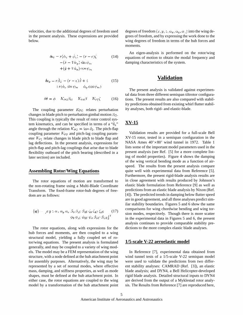
Validation results are provided for a full-scale BellXV-15 rotor, tested in a semispan configuration in theNASA Ames 40’�80’ wind tunnel in 1972. Table 1lists some of the important model parameters used in thepresent analysis (see Ref. [5] for a more complete list-ing of model properties). Figure 4 shows the dampingof the wing vertical bending mode as a function of air-speed. The results from the present analysis comparequite well with experimental data from Reference [5].Furthermore, the present rigid-blade analysis results arein close agreement with results produced by Johnson’selastic blade formulation from Reference [9] as well aspredictions from an elastic blade analysis by Nixon (Ref.[4]). The predicted trends in damping below flutter speedare in good agreement, and all three analyses predict sim-ilar stability boundaries. Figures 5 and 6 show the samecomparisons for wing chordwise bending and wing tor-sion modes, respectively. Though there is more scatterin the experimental data in Figures 5 and 6, the presentanalysis continues to provide comparable stability pre-dictions to the more complex elastic blade analyses.
1/5-scale V-22 aeroelastic model
In Reference [7], experimental data obtained fromwind tunnel tests of a 1/5-scale V-22 semispan modelwere used to validate the predictions from two differ-ent stability analyses: CAMRAD (Ref. [3]), an elasticblade analysis; and DYN4, a Bell Helicopter-developedrigid blade analysis. Detailed structural inputs to DYN4are derived from the output of a Myklestad rotor analy-sis. The Results from Reference [7] are reproduced here,
5American Institute of Aeronautics and Astronautics
along with stability predictions from the present analy-sis. Figure 7 shows the variation of wing vertical bendingmode damping with airspeed. Though the predicted levelof damping at velocities less than the flutter speed variesin each analysis, the stability boundary predicted by thepresent analysis agrees quite well with the experimentaldata, as well as the CAMRAD and DYN4 predictions.Figure 8 shows the variation in wing chordwise bendingmode damping. Here too, the present analysis is in closeagreement with both experiment and the CAMRAD andDYN4 results.
WRATS model
The 1/5-scale V-22 semispan model used for the testsdescribed in Reference [7] has undergone numerouschanges in configuration [10], [11] which have alteredthe model’s whirl flutter stability characteristics. Origi-nally developed as part of the JVX (V-22) research anddevelopment program in the 1980’s, the model, nowknown as the Wing and Rotor Aeroelastic Test System(WRATS), is in use as part of a joint NASA/Army/BellHelicopter Textron, Inc. research program. Reference[11] provides experimental whirl flutter stability datafor the WRATS model in its current configuration, butprovides no analytical results for comparison purposes.Whirl flutter stability predictions for the WRATS modelwere generated using the present analysis, with the in-put data shown in Table 2. For comparison, PASTA 4.1,the latest publicly available version of PASTA (Ref. [6]),a rigid blade stability analysis developed at NASA Lan-gley, was also run. Figures 9 – 12 show the compari-son of the present analysis to PASTA predictions and tothe experimental data from Ref. [11] for different ro-tor speeds and on- vs. off-downstop cases (Figure 11does not include PASTA results, since PASTA inputs fora rotor speed of 770 RPM were unavailable). Agree-ment between the present analysis and PASTA predic-tions, as well as between the present analysis and ex-periment, varies considerably from case to case. In Fig-ure 9 (742 RPM, off-downstop case), the present analy-sis and PASTA are in good agreement, and both capturethe experimental stability boundary. For the 888 RPM,off-downstop case in Figure 10, the present analysis andPASTA are still in close agreement, but both somewhatoverpredict the whirl flutter speed. At 770 RPM, on thedownstop (Figure 11), the present analysis underpredictsthe experimental stability boundary. In Figure 12 (888RPM, on-downstop), the present analysis seems to cap-ture the flutter speed well, while PASTA overpredicts thestability boundary.
Influence Of Unique Model Features
The present analysis incorporates several featuresunique among existing rigid blade stability analyses.The structural flap-lag coupling formulation used in thepresent analysis allows for variation of blade flap andlag frequency with collective pitch and also allows fora proper treatment of blade flexibility outboard of thepitch bearing. The analysis also retains separate gim-bal and blade flapping degrees of freedom, providing amore physically-based formulation than existing analy-ses. Blade pitch dynamics are also included. The influ-ence of these model features on tiltrotor aeroelastic sta-bility modeling is investigated below. Throughout thissection, the full-scale XV-15 semispan model tested atNASA Ames will be used to illustrate the influence ofvarious model features.
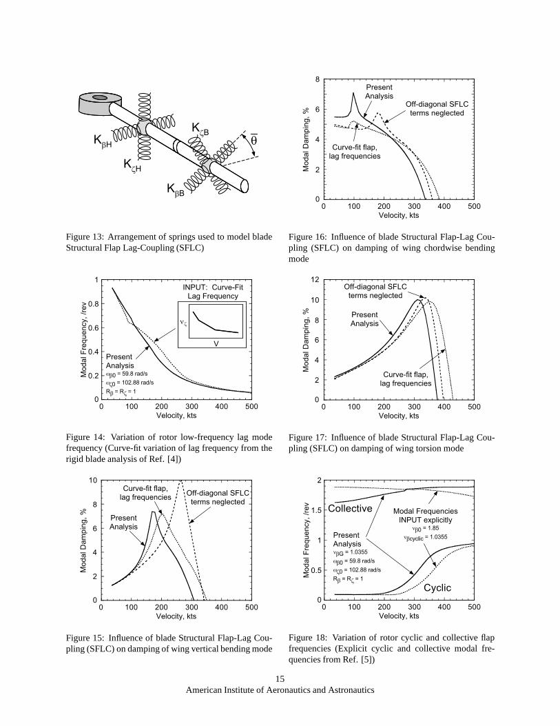
Structural Flap-Lag Coupling
The structural flap-lag coupling (SFLC) model inthe present formulation is commonly used in helicopterrigid-blade stability analyses ([12], [13]). In this for-mulation, flap-lag coupling is a result of blade flexibil-ity located outboard of the pitch bearing. Blade flap andlag stiffness is modeled using a set of orthogonal “hub”springs(K�H ;K�H) inboard of the pitch bearing, andorthogonal “blade” springs(K�B;K�B) outboard of thepitch bearing (see Figure 13). The relative angle betweenthe hub and blade springs(��) varies as the blade springsrotate with changes in collective pitch. Effective flap andlag flexural stiffnesses,K� andK� , can then be expressedas the stiffness of these springs acting in series.
K� =K�HK�BK�H +K�B
and K� =K�HK�BK�H +K�B
(18)
The structural flap-lag coupling parametersR� andR�are measures of the distribution of flap and lag flexibil-ity inboard and outboard of the pitch bearing, and aredefined as
R� =K�K�B
and R� =K�K�B
(19)
so that a value ofR� = 0 would represent a blade whereall the flap flexibility was located inboard of the pitchbearing, andR� = 1 would represent a blade where allthe flap flexibility was outboard of the pitch bearing. Thedistribution of lag flexibility varies similarly, but with pa-rameterR� . See Reference [13] for a detailed description
6American Institute of Aeronautics and Astronautics
of this formulation. In the present analysis, the elasticrestoring moments in flap and lag are then written as
�M�
M�
�= [Keff]
���
�(20)
=
�K�� K��K�� K��
����
�
whereKeff represents an effective stiffness matrix, theindividual terms of which are defined as
K�� =1
�
�K� + (R�K� �R�K�) sin
2 ���
K�� =1
�
�K� � (R�K� �R�K�) sin
2 ���
(21)
K�� = �1
�(R�K� �R�K�) cos �� sin ��
and
� = 1 + (2R�R� � R� �R�) sin2 �� (22)
+
�R� (1�R�)
K�K�
+R� (1�R�)K�K�
�sin2 ��
There are several important features to note about theabove formulation. First, Equations 20–22 show thatblade flap and lag stiffness is now a function of collec-tive pitch. By selecting proper values of the fundamentalblade flap and lag stiffnessesK� andK� , and couplingparametersR� andR� , the proper variation of blade flapand lag frequency with collective pitch may be modeled.
Second, the off-diagonal terms of equation 20 serve toelastically couple blade flap and lag motion. In the out-put of the eigen-analysis, this coupling will create elas-tically coupled flap/lag blade modes. The magnitude ofthe off-diagonal terms is of approximately the same or-der as the on-diagonal terms, since��may be a large angledue to the large values of collective pitch required to trimthe rotor in high speed forward flight. The off-diagonalterms therefore contribute significantly to the total bladeflap and lag elastic restoring moments, and will thus havea significant influence on blade flap and lag frequency.Other simple stability analyses do not properly model theelastic coupling of blade flap and lag motion, representedin the present analysis by the off-diagonal SFLC terms.
To model the variation of blade flap and lag frequen-cies with collective pitch, existing rigid blade stabilityanalyses require the variation to be explicitly input to theanalysis. Consider the case of blade lag frequency, whichfor the XV-15 varies from as high as 1.8/rev at low speed(low collective pitch) to about 1.2/rev at high speed. In
the PASTA analysis, the variation of frequency is input inthe form of tabular data. In Reference [4], a rigid bladestability analysis similar to the formulation in [5] wasused by Nixon to perform a preliminary whirl-flutter in-vestigation before moving to an elastic blade analysis.In this rigid blade analysis, Nixon modeled the varia-tion in lag frequency by fitting a curve to experimentaldata. By contrast, the present analysis allows a portionof the blade flap and lag flexibility to be located outboardof the pitch bearing, thus directly modeling the physi-cal mechanism behind the frequency variation. Figure14 shows the resulting output eigen-frequency of the lowfrequency cyclic lag mode for the present analysis usingthe above SFLC formulation, and for a case where thepresent analysis has been modified to use Nixon’s curve-fit frequency variation. The output frequency variationfrom the SFLC formulation closely matches that of thethe curve-fit frequency case. This shows that if the effec-tive flap and lag stiffness and the distribution of stiffnessinboard/outboard of the pitch bearing is properly spec-ified, then the present SFLC formulation is capable ofcorrectly modeling rotor frequency variation as a resultof changes in collective pitch, rather than requiring thevariation in frequency as an input.
Figures 15 – 17 examine the influence of coupledblade flap and lag motion on wing mode damping. Thebaseline results are compared to a case where the off-diagonal terms from Eq. 20 are set to zero. In figure 15,there is a noticeable change in the character of wing ver-tical bending mode damping when the off-diagonal termsare removed. Figures 16 and 17 show smaller changesin stability characteristics for the wing chord and tor-sion modes. In each case, however, prediction of thewhirl flutter stability boundary is affected, by as muchas 40 knots. The majority of the changes seen in Figures15 – 17 when eliminating the off-diagonal come fromthe resulting shift in flap and lag frequencies. For in-stance, the peak in wing vertical bending mode damp-ing in Figure 15 is shifted to a higher forward speedwhen the off-diagonal terms are neglected, due to thefrequency of the low-frequency cyclic lag mode crossingthe vertical bending mode frequency at a higher forwardspeed. If curve-fit flap and lag frequencies (as in Fig-ure 14) are used instead of the SFLC formulation fromthe present analysis, the resulting modal damping predic-tions (shown in Figures 15 – 17) are closer to the base-line. There is still a noticeable difference in the calcu-lated stability boundaries, however.
Since the uncoupled, curve-fit frequency case yieldsstability characteristics similar to the SFLC case, it canbe surmised that capturing the correct frequency varia-tion is a key requirement for accurate stability predic-tion. This explains why existing rigid blade analyses,
7American Institute of Aeronautics and Astronautics
which do not include elastic coupling of blade flap andlag motion, are still able to produce reasonable stabilitypredictions, provided the proper variation of flap and lagfrequency is specified. In the present analysis, the elasticcoupling of blade flap and lag is a crucial component ofthe SFLC formulation, which allows the flap and lag fre-quency variation to be determined from first principles.
It should be noted that the present structural flap-lagcoupling formulation may be used to model a hub flex-ure, or “coning hinge” set inboard of the pitch bearing,by selecting a value forR� close to zero and selecting aproper flap stiffnessK� . This has the effect of movingthe blade flap flexibility inboard of the pitch bearing.
Gimbal/Blade Flapping Degrees of Freedom
In the derivation of the rigid blade model in Refer-ence [5] all blade out-of-plane motions are treated by onerotating-frame degree of freedom, the blade flap angle(�). When the flap equation of motion is transformed tothe fixed system, the cyclic and collective flapping modesare assigned different frequencies to account for the dif-ferent root restraints in each case (the cyclic modes be-have as if they are hinged at the root, due to the presenceof the gimbal, while the collective mode is cantileveredat the root). Similarly, the PASTA analysis includes a ro-tor coning degree of freedom, as well as rotor (gimbal)longitudinal and lateral flapping degrees of freedom. Thefrequencies for the collective and cyclic flapping degreesof freedom are specified separately in the input to theanalysis. This is essentially amodalapproach, where thestability analysis is simply a math model, and the fre-quency of each mode must be provided as an input to theanalysis. Such an approach is different from the typicalhelicopter rigid blade stability analysis, where collectiveand cyclic flap frequencies are calculated from physicalproperties. For instance, the non-dimensional flap fre-quency for a helicopter is often defined as:
�2� = 1 +3
2�e+
K�I�2
(23)
In an expression for flap frequency such as that givenby Eq. 23, one cannot select a flap stiffnessK� whichsatisfies both the cyclic (gimbal) and collective (can-tilever) boundary conditions. In reality, the gimbal mo-tion and blade flapping represent two distinct physicaldegrees of freedom.
In the present analysis, separate gimbal (�G) and bladeflapping (�) degrees of freedom are retained. This al-lows a low-stiffness gimbal springK�G to be specified,yielding a low-frequency cyclic flap mode (dominated
by gimbal motion), while the higher flap stiffness of theblade produces a higher frequency coning mode. Thisapproach means there is no need to assign separate fre-quencies to each mode (collective vs. cyclic). Rather, thecorrect frequencies for each mode are obtained as outputsof the physical model. Figure 18 shows the output eigen-frequencies for the low-frequency cyclic gimbal modeand rotor coning mode from the present analysis, and forthe case where assigned frequencies are used as inputs,as in Reference [5].
It may appear that the cyclic blade flapping degreesof freedom (�1c; �1s) are redundant in the present analy-sis, since any cyclic flapping motion of the rotor shouldbe accommodated by the lower stiffness gimbal motion(�Gc; �Gs). Indeed, examination of the eigenvector as-sociated with the low-frequency cyclic mode shown inFigure 18 reveals that, although there is some contribu-tion from other degrees of freedom, the gimbal degreesof freedom dominate, and the contributions from�1c and�1s are small. So the behavior of this mode, dominatedby the gimbal motion, would not be greatly influenced bydropping the cyclic blade flapping degrees of freedom.
Consider however the rotor low-frequency lag modeshown in Figure 14. Physically, the reduction in lagmode frequency with increased forward speed (collectivepitch) occurs due to the rotation of the blade structuralaxes (blade flatwise bending becomes more in-plane). Inthe present analysis, this frequency variation is modeledby the structural flap-lag coupling formulation describedin the previous section. Since blade flap and lag motionsare elastically coupled, dropping the rotor cyclic flap de-grees of freedom from the analysis would make it im-possible to predict from first principles the variation oflag frequency with collective pitch. In the present anal-ysis, the cyclic flap and lag degrees of freedom coupleto represent in effect the first cyclic blade bending modeof the rotor, the displacement of which has componentsboth in-plane and out-of-plane.
Blade Pitch Dynamics
The present analysis includes a blade rigid pitch de-gree of freedom (perturbation in blade pitch due to con-trol system stiffness). None of the existing rigid bladeanalyses mentioned previously model blade pitch dy-namics. Reference [9] states that the primary influenceof blade pitch dynamics on tiltrotor aeroelastic stabil-ity is to introduce a destabilizing pitch-lag coupling. Inthe present analysis, the full pitch dynamic equationsof motion may be retained, or effective pitch-flap andpitch-lag coupling parameters may be extracted from the
8American Institute of Aeronautics and Astronautics
pitch equations of motion, with the equations themselvesdropped from the analysis.
In deriving the pitch equation of motion, another con-sequence of incorporating the structural flap-lag couplingmodel into the present analysis is encountered. From theSFLC formulation, the total blade flap and lag flexibilityis the sum of flap and lag flexibilities inboard and out-board of the pitch bearing.
[Keff]�1 = [Kin]
�1 + [Kout]�1 (24)
As a result of the distribution of flap and lag flexibility,the total flap and lag displacement may be defined as thesum of flap and lag displacement inboard and outboardof the pitch bearing.
���
�=
��in
�in
�+
��out
�out
�(25)
When the blade undergoes flap and lag motions, thefeather axis of the blade undergoes a rotation of�in out-of-plane and�in in-plane. At the same time, the bladeitself undergoes rotations of�out and�out relative to thefeather axis, as shown in Figure 19. These motions mustbe considered when formulating the blade pitch equa-tions of motion.
The relative contribution of(�in; �in) and(�out; �out) tothe total flap and lag deflection can be expressed as frac-tions of the total flap and lag angles. To begin, Equation25 is rewritten in terms of flap and lag flexibility multi-plied by the applied flap and lag moments:
[Keff]�1
�M�
M�
�=h[Kin]
�1+ [Kout]
�1i�
M�
M�
�(26)
Combining Equations 20 and 26 produces
[Keff]�1
[Keff]
���
�=
[Kin]�1
[Keff]
���
�+ [Kout]
�1[Keff]
���
� (27)
Comparing Equations 25 and 27, we can define thefollowing expressions for�in; �in; �out; and�out:
��in
�in
�= [Kin]
�1[Keff]
���
�=
�A BC D
����
�(28)
��out
�out
�= [Kout]
�1[Keff]
���
�=
�W XY Z
����
�(29)
where
A =1
�
�1�R� +
�R� �
K�K�
R�
�(R� � 1) sin2 ��
�
B = �1
�
�R� �
K�K�
R�
�(R� � 1) sin �� cos �� (30)
C =1
�
�R� �
K�K�
R�
�(R� � 1) sin �� cos ��
D =1
�
�1�R� +
�R� �
K�K�
R�
�(R� � 1) sin2 ��
�
and
W =1
�
�R� +
�R� �
K�K�
R�
�(R� � 1) sin2 ��
�
X =1
�
�R� �
K�K�
R�
�(R� � 1) sin �� cos �� (31)
Y = �1
�
�R� �
K�K�
R�
�(R� � 1) sin �� cos ��
Z =1
�
�R� +
�R� �
K�K�
R�
�(R� � 1) sin2 ��
�
Equations 28–31 show that the relative amount of flapand lag motion inboard and outboard of the pitch bear-ing is determined by the fundamental blade flap and lagstiffnessesK� andK� , the SFLC parametersR� andR� ,and by the collective pitch setting.
Now consider the forces and moments on the bladewhich contribute to the blade pitch equation of motion.Figure 20 illustrates the forces acting on a representativesection of the blade outboard of the pitch bearing. Thefigure is oriented such that the blade’s feather axis is di-rectly out of the page. In addition to the terms which arepart of the fundamental pitch dynamics (I� ��, the pitchingmoment due to the pitch inertia of the blade section, anddM�
aero, the perturbation aerodynamic pitching momentacting on the section), there are in-plane aerodynamicand inertial forces(Fx) acting on the blade which have amoment arm about the feather axis due to flapping out-board of the pitch bearing (�out), and out-of-plane forces(Fz) with a moment arm due to lag deflection outboardof the pitch bearing (�out). Radial forces on the blade(Fr) also have a moment arm around the feather axis,as a result of the displacement of the feather axis, due tomotion inboard of the pitch bearing (from�G; �in out-of-plane, and s; �in in-plane). Finally, there is also an elas-tic restoring moment at the root of the blade due to con-trol system stiffness (K�). Integrating all of these terms
9American Institute of Aeronautics and Astronautics
along the length of the blade produces the blade pitchequation of motion.
M� =
Z R
e
" Fz
aero+ Fzinert
�Frinert (�in + �P + �G)
!(r � e)�out
�
Fx
aero+ Fxinert
�Frinert (�in � s)
!(r � e)�out
+ I� ��+ dM�aero
#dr + K�� = 0
(32)
Consider Equation 32 for the case where the bladepitch degree of freedom is dropped. The terms in thelast line of Equation 32 would vanish. However, therewould still exist moments about the feather axis due toblade in-plane forces with a moment arm due to�out, andblade out-of-plane forces with a moment arm due to�out.Comparing the remaining terms in Equation 32 with theblade flap and lag equations of motion and Equation 25,the pitching moment can be expressed in terms of thecomponents of the elastic flap and lag restoring momentsacting along the feather axis:
M� = �M�elas�out +M�
elas�out (33)
Combining Equation 33 with the definitions in Equa-tions 20 and 29 yields
M� = � (K��� +K���) (Y � + Z�) (34)
+(K��� +K���) (W� +X�)
The blade pitching moment is thus non-linear in flapand lag. This moment produces a pitch deflection due toflexibility of the control system
�� = ��M�
K�(35)
Linearizing about the steady-state flap and lag deflec-tions ��0 and ��0, effective pitch-flap and pitch-lag cou-pling parameters can be defined as
KP� = �@�
@�(36)
=1
K�
"2(YK�� �WK��) ��0
+(ZK�� � (X � Y )K�� �WK��)��0
#
KP� = �@�
@�(37)
=1
K�
"(ZK�� � (X � Y )K�� �WK��) ��0
+2(ZK�� �XK��)��0
#
The effective pitch-flap and pitch-lag couplings de-fined above have been derived following a procedure setout in Reference [14], significantly expanded to accountfor the present structural flap-lag coupling formulation.
Note that the effective pitch-flap and pitch-lag cou-pling parameters both have contributions from the off-diagonal terms in the SFLC formulation. The expres-sions in [14] do not include these contributions. If thetrim lag angle��0 is assumed negligible, the pitch-flapcoupling parameterKP� (Eq. 36) is purely a result ofthe presence of off-diagonal terms (Y andK��). Due tothe large values of collective pitch present in a tiltrotor,these off-diagonal terms are not small. In the presentanalysis, the magnitude ofKP� is comparable toKP� .Figure 21 shows the variation of these coupling param-eters as calculated in the present analysis for the XV-15semispan model. In Reference [9], Johnson estimates aneffective pitch-lag coupling for this model of about -0.3,based on his elastic blade analysis. Near this configura-tion’s stability boundary, the present analysis predicts asimilar level of coupling.
Figures 22, 23, and 24 examine the influence of bladepitch modeling on whirl flutter stability. The resultspresented thus far for the present analysis have not in-cluded the blade pitch equations of motion, but did in-clude the derived pitch-flap and pitch-lag coupling pa-rameters. Comparing these results to those obtained fromthe present analysis with full pitch dynamics included, itis clear that the coupling parameters do capture the pri-mary influence of blade pitch dynamics on whirl flutterstability. Removing both coupling parameters from thepresent analysis causes the predicted stability boundaryto increase by over 100 knots. Removing just the pitch-flap coupling parameter and retaining the pitch-lag cou-pling produces a much smaller, but not negligible, effecton the stability boundary. These coupling parameters arevery destabilizing, and must be correctly accounted forin order to obtain accurate stability predictions.
Examining Equations 36 and 37, some of the impor-tant design parameters which influence the magnitude ofthese couplings can be identified. First, the couplingsdepend on the distribution of blade flexibility inboardand outboard of the pitch bearing. As more flexibilityis placed inboard, the termsW;X; Y; andZ all decreasein magnitude. If all the blade flexibility is inboard of
10American Institute of Aeronautics and Astronautics
the pitch bearing, the coupling terms vanish entirely. Itis this observation that provides the motivation for theuse of a flexured hub on the V-22. The hub flexure al-lows more trim elastic coning deflection to take placeinboard of the blade pitch bearing, thus minimizing theundesirable coupling [11]. The XV-15 semispan rotortested at Ames did not have a hub flexure. As a result, itsstability boundary was reduced greatly by the presenceof the destabilizing couplings. Secondly, the magnitudeof the destabilizing pitch-flap and pitch-lag couplings isproportional to rotor pre-cone. In the case of ideal ro-tor pre-cone, the trim coning deflection��0 will be zero,eliminating the couplings (��0 is assumed negligible). Fortiltrotors, pre-cone is typically set for the hover condi-tion, leading to higher than ideal pre-cone in cruise. Fi-nally, the couplings are inversely proportional to controlsystem stiffness,K�. Increased control system stiffnesswill also reduce the magnitude of the destabilizing cou-plings.
Concluding Remarks
The tiltrotor stability analysis described in this paperretains the simplicity of a rigid-blade model, while cor-rectly accounting for the variations in blade frequency,as well as the flap-lag, pitch-flap, and pitch-lag cou-plings necessary for accurate whirl flutter stability pre-diction. The model shows good agreement with exper-imental data and more complex elastic blade analyses.Investigation of the influence of several features of themodel revealed:
1. Including structural flap-lag coupling terms allowsthe variation of blade flap and lag frequencies withcollective pitch to be modeled from first principles,instead of being treated as an input to the analysis,as in existing rigid-blade analyses.
2. Elastic coupling of blade flap and lag motion due tothe off-diagonal structural flap-lag coupling termsin the present analysis contributes significantly tothe blade flap and lag elastic restoring moments, andis important for correct evaluation of rotor flap andlag frequencies.
3. The present analysis retains a separate degree offreedom to represent each physical degree of free-dom being modeled (e.g. gimbal vs. blade flap-ping). There is thus no need to assign separatecollective and cyclic modal frequencies. By hav-ing both a soft gimbal spring and a stiff blade flapspring, the analysis automatically produces a lower
frequency cyclic flap mode and a higher frequencyconing mode.
4. The present analysis models blade pitch dynamics,accounting for the presence of flexibility outboardof the pitch bearing. Alternatively, expressions foreffective pitch-flap and pitch-lag coupling parame-ters have been extracted from the pitch dynamics,and the pitch equations of motion may be dropped.
5. The primary influence of of blade pitch dynamics isa destabilizing pitch-lag coupling. Pitch-flap cou-pling has a smaller, but still important effect. Thesecouplings must be included to produce accurate sta-bility predictions.
6. Increasing blade flexibility inboard of the pitchbearing, reducing rotor pre-cone, and increasingcontrol system stiffness will all reduce the mag-nitude of the destabilizing pitch-flap and pitch-lagcouplings.
Acknowledgments
The authors wish to acknowledge Richard L. Ben-nett, Bell Helicopter Textron, Inc., and David J. Piatakat NASA Langley Research Center for their assistance inobtaining input parameters for the WRATS model.
References
[1] Johnson, W., “Recent Developments in the Dy-namics of Advanced Rotor Systems,” NASA TM86669, March, 1985.
[2] Johnson, W., “Analytical Model for Tilting Propro-tor Aircraft Dynamics, Including Blade Torsion andCoupled Bending Modes, and Conversion ModeOperation,” NASA TM X-62,369, May, 1974.
[3] Johnson, W.,A Comprehensive Analytical Model ofRotorcraft Aerodynamics and Dynamics, JohnsonAeronautics, Palo Alto, CA, 1988.
[4] Nixon, M. W., Aeroelastic Response and Stabil-ity of Tiltrotors with Elastically-Coupled Compos-ite Rotor Blades, Ph.D. thesis, University of Mary-land, 1993.
[5] Johnson, W., “Dynamics of Tilting Proprotor Air-craft in Cruise Flight,” NASA TN D-7677, May,1974.
11American Institute of Aeronautics and Astronautics
[6] Kvaternik, R. G.,Studies in Tilt-Rotor VTOL Air-craft Aeroelasticity, Ph.D. thesis, Case Western Re-serve University, 1973.
[7] Popelka, D., Sheffler, M., and Bilger, J., “Corre-lation of Test and Analysis for the1=5-Scale V-22Aeroelastic Model,”Journal of the American Heli-copter Society, vol. 32, no. 2, April 1987, pp. 21–33.
[8] Parham, J., C., T., Chao, D., and Zwillenberg, P.,“Tiltrotor Aeroservoelastic Design Methodology atBHTI,” Proceedings of the 45th Annual AHS Fo-rum, Boston, MA, May 22–24, 1989.
[10] Settle, T. B. and Kidd, D. L., “Evolution andTest History of the V-22 0.2-Scale AeroelasticModel,” Journal of the American Helicopter Soci-ety, vol. 37, no. 1, January 1992, pp. 31–45.
[11] Piatak, D. J., Kvaternik, R. G., Nixon, M. W.,Langston, C. W., Singleton, J. D., Bennett, R. L.,and Brown, R. K., “A Wind-Tunnel ParametricInvestigation of Tiltrotor Whirl-Flutter StabilityBoundaries,” Proceedings of the 57th Annual AHSForum, Washington, DC, May 9–11, 2001.
[12] Ormiston, R. A. and Hodges, D. H., “LinearFlap-Lag Dynamics of Hingeless Helicopter RotorBlades in Hover,”Journal of the American Heli-copter Society, vol. 17, no. 2, April 1972, pp. 2–14.
[13] Gandhi, F. and Hathaway, E., “Optimized Aeroelas-tic Couplings for Alleviation of Helicopter GroundResonance,”Journal of Aircraft, vol. 35, no. 4,July–August 1998, pp. 582–590.
[14] Johnson, W.,Helicopter Theory, Dover Publica-tions, Inc., New York, 1994, pp. 408–411.
Table 1: XV-15 Full-scale Test: Model PropertiesNumber of blades,N 3