American Institute of Aeronautics and Astronautics
1
Acoustic Shielding of Rocket Payloads within Launch Fairings
Tyler Engberg1, Jacob Kizer2, Umesh A. Korde3
South Dakota School of Mines and Technology, Rapid City, SD, 57701
This paper discusses the need for noise shielding methods as incorporated into payload fairings of launch vehicles and potential approaches to the problem. The first design considered here is an active solution and involves the actuation of a membrane. Currently we are studying a simpler scale based on using a duct. The second is a semi-active solution which relies on layers of piezoelectric elements driving high-impedance circuits. Results from acoustic modeling studies on the fairing and payload are presented here along with results from scale model testing.
I. Introduction The need for acoustic shielding of payloads has acquired greater importance in recent years since the introduction of light-weight composite launch fairings. While such fairings successfully protect the payload against structural loads, their acoustic transmission characteristics are less than ideal. It has been found, however, that at certain times during the first minutes of a launch, both structural and acoustic loads are significant and have the potential to damage the payload1. To a large extent, higher frequency noise components in the launch noise can be filtered using passive acoustic blankets, which do not perform well in the low-frequency range1. Another passive method is that of a composite chamber core method developed by the U.S. Air Force Research Laboratory. This method was found to perform as well as the passive acoustic blankets2. A third passive method consists of using tuned vibration absorbers to reduce noise within the payload fairing3. In contrast to passive methods, active noise shielding works well at low frequencies, but the volume in which noise shielding is effective is often limited. Different methods of active noise shielding of payloads have been attempted. Some of these include using structural actuators attached to the wall of the fairing do dampen acoustic noise and using a loud speaker located within the fairing to actively cancel acoustic noise4,5. This paper outlines preliminary work on a membrane-based active cancellation technique, and also discusses ongoing analytical and experimental work that would lead to a semi-active technique which relies on layers of piezoelectric elements driving high-impedance circuits. The active solution explores using a speaker actuated membrane to shield noise within a duct. This technique would then be implemented to reduce noise within a payload fairing. Other active noise control solutions have been tested using ducts including actively controlling membrane tension using PVDFs and actively controlling noise canceling speakers6-8. Our goal is to design a noise shielding technique that would perform well with modern composite launch fairings, and while we expect much of our work to focus on the semi-active technique, there may be specific application needs where a combination of the two techniques proves to be more successful. In light of this, the goal of the first part of the project is a basic study on noise shielding within a duct using a thin membrane. This work is described in Parts A-C below. The second part of the project is to study noise propagation into cylindrical fairings with the payload inside, both with and without the protective lining. Much of the current work on this has focused on analytical modeling, while preliminary experimental tests of a scaled model of a launch vehicle fairing are underway. This effort is described in section II.
American Institute of Aeronautics and Astronautics
2
A. Membrane Tensioning Structure The membrane is located in the center of the duct and is actuated by a small speaker located behind it. The actuation will shield against transmitted and radiated waves from upstream of the membrane, minimal noise will exist downstream of the duct. Eventually, the actuating speaker will react based on feedback given to it by a microphone located downstream of the membrane. Some factors that will play into the movement of the membrane are membrane material type, tension and thickness. The first task of this project was to build a structure that would evenly tension a membrane. It was concluded that a circular structure would be best suited to apply even tension. A preliminary design was a flanged structure where the membrane is stretched over the male side of the flange and a female side bolts snuggly over the top to stretch the membrane; this system is denoted as the first stage. An elastic retainer is used to keep the original membrane tension while the system is being bolted down. A revised version was built that is a little bigger to fit our appropriate duct and also has an optional second tensioning stage. This second stage bolts onto the first stage and provides for greater tension of the membrane than is possible with just the first stage. The tension is determined by how far the bolts are tightened. This version gives us the ability to test the tension factor in the membrane. The whole tensioning system, first stage and optional second stage, can be seen in figures 1, 2, and 3.
Figure 2. Tensioning System with Membrane Figure 3. Tensioning System with all Stages B. Duct and System Design
The second task of the project was to build a circular duct to be used for testing. The duct was to be constructed to ASTM standards for an impedance tube9. To abide by these standards the monitoring microphones must have a cross section that is 5% of the total cross section of the tube. Also, the test frequency range of the tube is governed by:
f > 0.75 c/(l – d)
and
f < 0.586 c/d
where: f = frequency, Hz
c = speed of sound in tube l = length of tube
d = diameter of tube The duct was built using two 36 in. long by 4 in. diameter clear acrylic tubes. Each tube is considered a separate impedance tube and with the dimensions given above they satisfy the ASTM standards for the test frequency range
Figure 1. Cross Section of Tensioning Structure
American Institute of Aeronautics and Astronautics
3
desired. Each one sits on top of two supports and slide together to hold the membrane tensioning structure. A 1.42 in. diameter speaker is positioned inside the duct 1.125 in downstream from the membrane, a 3 in. diameter speaker sits at the upstream opening of the duct, and a monitoring microphone sits at the downstream opening of the duct. The whole set up can be seen in Figure 4. The two speakers located in the duct are each powered by an arbitrary wave generator (AWG), each providing a pure sine wave of the same frequency, shown in Figure 5. These two AWGs are set up so that the signal from one can be phase shifted a known amount with reference to the other. This is necessary to find the phase shift to optimize the amount of noise shielding at a given frequency. An oscilloscope, seen in Figure 5, is set up to monitor the phase shift between the two signals running from the AWGs to the speakers. This is done to verify that the AWGs are actually phase shifting the signals. Finally, the microphone situated at the end of the duct is hooked up to a computer, Figure 5. The computer is running software that displays the Fast Fourier Transform of the signal given by the microphone in real time. This is handy to have because it allows the amount of noise shielding to be monitored in real time as the phase of the two speaker signals is shifted.
Figure 5. Duct Electronic System
C. Preliminary Testing The first test was conducted with the two speaker signals completely in phase. Using the dimensions given above for the placement of the components in the duct, the frequency where the acoustic waves coming from each of the speakers hit the membrane in phase was calculated. The frequency was found to be776.63 Hz. Running the AWGs at this frequency, FFT plots were developed from the microphone signal under three different conditions. The first was with just the big speaker running, the second is with just the small speaker running, and the third was with both speakers running. These results can be seen in figures 6-8.
Figure 4. Duct in test
American Institute of Aeronautics and Astronautics
4
0 100 200 300 400 500 600 700 800 9000
500
1000
1500
X: 778Y: 1205
0 100 200 300 400 500 600 700 800 900
0
500
1000
1500
X: 778Y: 117
Figure 6. FFT Big Speaker Figure 7. FFT Small Speaker
0 100 200 300 400 500 600 700 800 9000
500
1000
1500
X: 778Y: 1087
Figure 8. FFT Both Speakers
The results show that the amplitude of the big speaker is cancelled by the amplitude amount of the small speaker almost exactly when both speakers are running. The second test was conducted to find the phase shift at each frequency where the maximum amount of noise shielding occurred. This was done by monitoring the FFT of the microphone signal using the real time FFT software. At each frequency the phase shift between the two speaker signals was varied until the point where the maximum amount of noise shielding was found. This was done through the whole test frequency range and the results can be seen in figure 9.
0
50
100
150
200
250
300
350
0 200 400 600 800 1000 1200 1400Frequency
Sh
ift
Real
Figure 9. Phase Shift for Maximum Noise Shielding
American Institute of Aeronautics and Astronautics
5
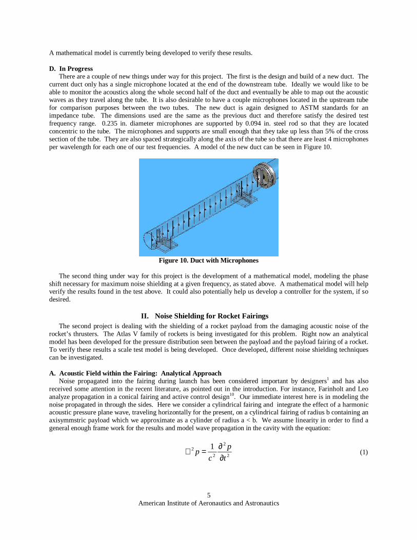
A mathematical model is currently being developed to verify these results. D. In Progress There are a couple of new things under way for this project. The first is the design and build of a new duct. The current duct only has a single microphone located at the end of the downstream tube. Ideally we would like to be able to monitor the acoustics along the whole second half of the duct and eventually be able to map out the acoustic waves as they travel along the tube. It is also desirable to have a couple microphones located in the upstream tube for comparison purposes between the two tubes. The new duct is again designed to ASTM standards for an impedance tube. The dimensions used are the same as the previous duct and therefore satisfy the desired test frequency range. 0.235 in. diameter microphones are supported by 0.094 in. steel rod so that they are located concentric to the tube. The microphones and supports are small enough that they take up less than 5% of the cross section of the tube. They are also spaced strategically along the axis of the tube so that there are least 4 microphones per wavelength for each one of our test frequencies. A model of the new duct can be seen in Figure 10.
Figure 10. Duct with Microphones
The second thing under way for this project is the development of a mathematical model, modeling the phase shift necessary for maximum noise shielding at a given frequency, as stated above. A mathematical model will help verify the results found in the test above. It could also potentially help us develop a controller for the system, if so desired.
II. Noise Shielding for Rocket Fairings The second project is dealing with the shielding of a rocket payload from the damaging acoustic noise of the
rocket’s thrusters. The Atlas V family of rockets is being investigated for this problem. Right now an analytical model has been developed for the pressure distribution seen between the payload and the payload fairing of a rocket. To verify these results a scale test model is being developed. Once developed, different noise shielding techniques can be investigated.
A. Acoustic Field within the Fairing: Analytical Approach
Noise propagated into the fairing during launch has been considered important by designers1 and has also received some attention in the recent literature, as pointed out in the introduction. For instance, Farinholt and Leo analyze propagation in a conical fairing and active control design10. Our immediate interest here is in modeling the noise propagated in through the sides. Here we consider a cylindrical fairing and integrate the effect of a harmonic acoustic pressure plane wave, traveling horizontally for the present, on a cylindrical fairing of radius b containing an axisymmstric payload which we approximate as a cylinder of radius a < b. We assume linearity in order to find a general enough frame work for the results and model wave propagation in the cavity with the equation:
2
2
22 1
t
p
cp
∂∂=∇ (1)
American Institute of Aeronautics and Astronautics
6
Where: c= the speed of sound in air
p = magnitude of the pressure disturbance and
2
2
222 11
θ∂∂+
∂∂+
∂∂=∇
rrrr (2)
Following Morse and Ingard11, we write:
))cos(( ctrikop
oePP −−= θθ (3)
where:
λπ /2=k , lambda is the wave number c= the speed of sound in air
oθ = the direction from which the wave approaches
Representing the incident pressure in terms of cylindrical waves:
ti
imo
mop ekrJmPP ωθθε −
∞
=
−= ∑0
)()(cos (4)
Where mε is the jacobian symbol such that mε = 1 for m = 0, and mε = 2 for m ≥ 2. ω denotes the wave
frequency ( kc=ω ). The pressure due to the wave scattered by the outer cylinder b can be written as11:
tim
mms ekrmHAP
b
ω−∞
=∑= )(cos )1(
1
(5)
Where )()()()1( kriNkrJkrH mmm += denotes the Hankel Function of 1st kind and order 1, with mJ and mN
respectively denoting the Bessel Functions of the 1st kind and the mth order Weber Function. The pressure due to the scattered wave arising from the cylinder at r = a can be expressed as:
[ ] tim
mmS ekrHmBP
a
ωθ −∞
=∑= )(cos )1(
1
(6)
The total pressure at a point (θ,r ) due to the resulting wave field, subject to linearity given by:
ab SSp PPPP ++= (7)
Knowing that at each boundary r = b and r = a, the total velocity u normal to the cylinder walls is zero, with:
r
P
t
u
∂∂−=
∂∂ρ (8)
American Institute of Aeronautics and Astronautics
7
For a < r < b and r > b, and
r
P
t
u
∂∂−=
∂∂
'ρ (9)
For r < a where the wave speed is 'c and the wave number is 'k . We have:
0=++rrr pab UUU at r = b (10)
And
0' =+++rrrr paab UUUU (11)
Where 'raU is the velocity in r < a from the scattered field due to the cylinder at r = a.
If we truncate the summations in equations (4) – (6) to M terms, we have 2M+1 equations to solve for the coefficients Am, Bm for m = 0,…, M. Figures 12 and 13 plot the pressure field in the region a < r < b for a fairing with radius of 1m and payload radius = 0.3m and frequencies of 300 Hz and 500 Hz, respectively.
-1
-0.50
0.51
-1
-0.5
0
0.5
10
5000
10000
15000
x
Sound pressure amplitude between cylinders, f = 500 Hz
y
p a
Figure 12. Pressure Field at 300 Hz Figure 13. Pressure Field at 500 Hz
American Institute of Aeronautics and Astronautics
8
Figures 14 and 15 plot the pressure field in the region a < r < b for a fairing with radius of 2in and payload radius = 0.5in and frequencies of 300 Hz and 500 Hz, respectively. These dimensions correspond to the scale rocket model presented in the following section.
-0.1-0.05
00.05
0.1
-0.05
0
0.056
6.2
6.4
6.6
6.8
x
Sound pressure amplitude between cylinders, f = 300 Hz
y
p a
-0.1-0.05
00.05
0.1
-0.05
0
0.055.5
6
6.5
7
7.5
x
Sound pressure amplitude between cylinders, f = 500 Hz
y
p a
Figure 14. Scaled Pressure Field at 300 Hz Figure 15. Scaled Pressure Field at 500 Hz
Calculations were carried out based on the analysis, and the waves are assumed to approach from a sector oθ = 0 to
30 degrees. The pressure field in the cavity is found to be strongly dependant on the wave frequency and the site of the payload relative to the fairing. B. Acoustic Field within the Fairing: Scale Model Testing Approach A scale model of a rocket fairing and payload from the Atlas V family of rockets has been constructed. Microphones are strategically placed in the space between the payload and the fairing and in the wall of the payload. Monitoring these microphones will provide data to verify the analytical results above. Three speakers will be placed around the scale model to account for the acoustic noise from the thrusters. A Model of this without microphones can be seen in Figure 16. Information given to us about the Atlas V family of rockets shows that their thrusters are capable of acoustic pressure levels around 140 dB at the fairing1. Assuming that the base Pressure is around 2 x 10^-5 Pa, this translates to around 200 Pa RMS. In order for us to develop a suitable model for testing, the pressure level had to be scaled. To do this the pressure was non-dimensionalized using known parameters in the system; namely: length or diameter, air density and gravity. The non-dimensionalization shows that the RMS pressure varies linearly with how the geometry is scaled. Two geometry scales are thought feasible for testing, one at 1/20 scale and one at 1/50 scale. These scale the sound pressure levels to 114 dB and 106 dB, respectively. However, due to the size of tubing readily available the first actual scale rocket model is 1/41.3 scale. This would scale the sound pressure level down to 107.67 dB. Tables 1-4 in Appendix A show the geometry and pressure scales for the payload fairing on the Atlas V family of rockets. The actual 1/41.3 scale model for the Atlas V 400 Extended rocket can be seen in Figures 17 and 18.
Figure 16. Scale Rocket Model
American Institute of Aeronautics and Astronautics
9
The modeling system consists of the microphones located within the model rocket which are hooked in to a powered circuit board located beneath the model platform. The circuit board acts as the power supply to the microphones and helps filter out noise in the signals from the microphones. The signal is then run to a MOTU 24 I/O audio interface that is linked to a sound card in a computer. The signals are read from the sound card via SONAR 8 music software that allows us to record all the microphones simultaneously. The monitoring system can be seen on Figure 19.
Figure 17. Scale Model Top Figure 18. Scale Model Side
Figure 19. Monitoring System
American Institute of Aeronautics and Astronautics
10
Results from a scale model at 500 Hz with microphones in the gap can be seen in Figure 20 below.
-2
-1
0
1
2
-2
-1
0
1
2
0
5
10
xy
z70
75
80
85
90
95
C. Noise shielding Techniques Different materials are currently being tested in an impedance tube to determine their noise shielding properties. Piezoelectric composite materials show promise because they are relatively lightweight, flexible, and have the ability to absorb vibrations. Advanced Cerametrics Inc manufactures multiple composite materials that have interesting properties. These materials include PFC (piezoelectric fiber composite), PFCB (piezoelectric fiber composite biomorph), and PMC (piezoelectric multilayer composite). These composites all use the same piezoelectric fiber but are arranged differently within the epoxy to produce different properties. The PFC has piezoelectric ceramic fibers that are secured together by epoxy in the patch and is 0.3mm thick. The PFCB has two layers of PFC with a shim between them which increases the thickness to 1.3mm. The PMC has multiple layers of fibers which are imbedded randomly in a polymer matrix. These composites should provide a range of differing effects when tested in the impedance tube and provided data that can be compared to other non-piezoelectric materials that will be tested.
III. Conclusion
This paper discusses recent and ongoing studies on methods to protect the payloads within launch vehicles against the intense acoustic loads generated during the initial phase of the launch sequence. Both active and semi-active techniques are being examined, and the problem is being studied both from analytical and experimental points of view. Analytical models predict a strong dependence of the relative payload/fairing geometry and frequency. Scale models of launch fairings being prepared for testing were described, and we expect to present further test results at the conference. Early results on an active technique based on a flexible membrane were also discussed.
Figure 20. Monitoring System
American Institute of Aeronautics and Astronautics
American Institute of Aeronautics and Astronautics
12
Acknowledgments This work is supported by the Air Force Research Laboratory, Space Vehicles Directorate (AFRL/RV).
Particular thanks are due to Jeremy Banik of AFRL/RV for his insight and continued support. Much gratitude goes to Miles Wickersham and the other co-workers in the Advanced Dynamics lab at the School of Mines.
References [1] ILS Report, Atlas Launch System Mission Planner’s Guide, Atlas V Addendum, rev. 8, Dec. 1999,
http://www.ilslaunch.com [2] Lane, S. A., Henderson, K., and Williams, A., “Chamber Core Structures for Fairing Acoustic Mitigation,” Journal of Spacecraft and Rockets, Vol. 44, No. 1, 2007, pp. 156-163 [3] Howard, C. Q., Hansen C. H., and Zander, A. C., “Noise Reduction of a Rocket Payload Fairing Using Tuned
Vibration Absorbers with Translational and Rotational DOFs,” Proceedings of the Annual Conference of the Australian Acoustical Society, 2005, pp.165-171
[4] Glaese, R. M., and Anderson, E. H., “Active Structural-Acoustic Control for Composite Payload Fairings,” Proceedings of the SPIE Smart Structures and Materials Conference, SPIE Vol. 3668, 1999, pp. 450-461
[5] Kemp, J. D., and Clark, R. L., “Noise Reduction in a Launch Vehicle Fairing Using Actively Tuned
Loudspeakers,” Journal of the Acoustical Society of America,” Vol. 113, No. 4, Pt. 1, 2003, pp. 1986-1994 [6] Van Niekerk, J. L., and Tongue, B. H., “Active Control of a Circular Membrane to Reduce Transient Noise
Transmission,” Journal of Vibrations and Acoustics, Vol. 17, 1995, pp. 252-258 [7] Hull, A. J., Radcliffe, A. J., and Southward, S. C., “Global Active Noise Control of a One-Dimensional
Acoustic Duct Using a Feedback Controller,” Journal of Dynamic Systems, Measurement, and Control, Vol. 115, 1993, pp. 488-494
[8] Esmailzadeh, E., Alasty, A., Ohadi, A. R., “Hybrid Active Noise Control of a
One-Dimensional Acoustic Duct,” Journal of Vibrations and Acoustics, Vol. 124, 2002, pp. 10-18 [9] ASTM International, Standard Test Method for Impedance and Absorption of Acoustic Materials by Impedance Tube Method, Designation: C 384, May 2004 [10] Frinholt, K. M. and, Leo, D. J., “Acoustic Modeling and Control of Conical Enclosures,” Journal of
Vibrations and Acoustics, Vol. 125, 2003 [11] Morse, PM and Ingard KU, Theoretical Acoustics, McGraw-Hill, NY, 1968, chapter 8